Embed Size (px)
Citation preview
VELTECH HIGHTECH Dr.RANGARAJAN Dr.SAKUNTHALA
ENGINEERING COLLEGEDEPARTMENT OF MECHANICAL ENGINEERING
Subject code : ME 2352
Subject Name: DESIGN OF TRANSMISSION SYSTEMS
Question Bank
UNIT-I
DESIGN OF TRANSMISSION SYSTEMS FOR FLEXIBLE ELEMENTS
Selection of V belts and pulleys – selection of Flat belts and pulleys - Wire ropes and
pulleys – Selection of Transmission chains and Sprockets. Design of pulleys and
sprockets.
PART-A
Belt drives
1. What is the effect of centre distance and diameter of pulley on the life of a belt?
[AUC- Dec 2005]
2. What are the various losses in the power transmission by belts? [AUC-Dec2005]
3. Explain the term “Crowning of pulley”. Specify the purpose of it. [AUC-May 2006]
4. Centrifugal forces add to belt tension without increasing the power capacity.
Justify the statement.[AUC-May2008]
5. State the law of belting.
6. How are the ends of flat belt joined?
7. In what ways the timing belts are superior to ordinary V-belts? [AUC-May 06,07]
8. Why tight-side of the belt should be at the bottom side of the pulley? [AUC-
Dec2004,May 2006]
9. How is V-belt specified? [AUT-Dec2010]
10. What is slack adjuster? [AUC-Dec 2004]
11. Sketch the cross section of a V-belt and label its important parts. [AUC-Dec 09]
12. What will be the effect on limiting ratio of tensions of a belt if the co-efficient of
friction between the belt and the rim of pulley is doubled while angle of lap
remains the same? [AUC-Dec 2007]
13. Derive the expression for tension ratio of belts.[AUC-May 2007]
www.vidyarthiplus.com
SRI RAMAKRISHNA INSTITITE OF TECHNOLOGY PERUR,COIMBATORE
GOPINATH.GASST.PROF
ME 6601
SRIT,CBEGOPINATH.G - AP/MECH
2 Design of Transmission Systems
Veltech Hightech Dr.Rangarajan Dr.Sakunthala Engg College. Avadi
14. Give the relationship of ratio of tensions in a V-belt drive. [AUC-May-‘08,2010]
15. Define: maximum tension in a belt. [AUC-May2010]
16. State reasons for V-belt drive being preferred to flat belt drive? [AUC: Dec 2010]
17. Define creep & slip in belts.
Chain drives
18. What are the five parts of roller chain? [ AUT-April 2010]
19. What is chordal action (Polygonal action) in chain drive? [AUT-Dec2010]
20. What do you mean by galling of roller chains? [AUC: Dec 2010]
21. How does a hoisting chain differ from a roller chain? .[AUC-May2008]
22. In what way silent chain is better than ordinary driving chain? [AUC-Dec2007]
23. What is done to accommodate initial sag in chain drives? [AUC-May2007]
24. What do you understand by simplex, duplex and triplex chain?[May2007]
Rope drives
25. How is a wire rope specified? [AUC-May2007]
26. What do you understand by 6x9 constructions in wire ropes? [AUC-May2008]
27. Sketch and name different type of compound wire ropes.[AUC-2004]
28. Distinguish regular lay and long lay ropes.
29. Give some application of wire ropes.
PART-B
Flat Belts
1. A leather belt 9mm x 250mm is used to drive a CI pulley 900mm in diameter at
336rpm. If the active arc on the smaller pulley is 120o and stress in tight side is
2Mpa, find the power capacity of the belt. The density of the leather may be taken
as 980 kg/m3 and coefficient of friction of leather on CI is 0.35. [AUC-May 2007]
2. Design a FLAT belt drive to transmit 10 KW at 400 rpm. The speed ratio is 3. The
distance between the pulley centres is 600 mm. the drive is for a crusher. [AUT-
Dec2010]
3. Design a flat belt drive to transmit 10KW @1000rpm. The centre distance is 2m
and the speed ratio is 3.
www.vidyarthiplus.com
SRI RAMAKRISHNA INSTITUTE OF TECHNOLOGY,COIMBATORE

T.V.B.Babu ME(CAD/CAM)
Department of Mechanical Engineering
3
Veltech Hightech Dr.Rangarajan Dr.Sakunthala Engg College. Avadi
4. It is required to design a leather crossed belt drive to connect 7.5 KW, 1440rpm
electric motor to a compressor running at 480rpm. The distance between the
centers of the pulley is twice the diameter of the larger pulley. The belt should
operate at 20m/s and its thickness is 5mm. Density of leather is 950kg/m3 and
permissible stress is 5.6MPa.
V- Belts
1. A V- belt drive consists of three V- belts in parallel on grooved pulleys of the
same size. The angle of groove is 30° and the coefficient of friction 0.12. The
cross sectional area of each belt is 800 mm² and the permissible safe stress in the
belt material is 3MPa. Calculate the power that can be transmitted between two
pulleys 400mm in diameter rotating at 960rpm. [AUC: Dec 2010]
2. (i) Select a suitable V-belt drive to connect a 7.5Kw, 1440 rpm
induction motor to run a fan at a approximately 480 rpm for a service of
hr per day. The space available for center distance is 1m.
(ii) Enlist the merits and demerits of V -belt over flat belt. [AUC-May2008]
3. A V-belt drive is to transmit 40KW in a heavy duty saw mill which works in two
shifts of 8hours each. The speed of motor shaft is 1440 rpm with the approximate
speed reduction of 3 in the machine shaft. Design the drive and calculate the
average stress induced in the belt.
4. Design a V-belt drive and calculate the actual belt tension and average stress for
the following data. Driven pulley diameter, D= 500 mm, driver pulley diameter,
d=150 mm, center distance C=925 mm, speed n1 = 1000 rpm, n2 = 300 rpm and
power, P = 7.5 kW.
5. Design a V-belt drive to transmit 50KW at 1440 rpm from an electric motor to a
textile machine running 24 hours a day. The speed of the machine shaft is 480
rpm.
www.vidyarthiplus.com
GOPINATH.G
SRIT, CBE
GOPINATH.G - AP/MECH
4 Design of Transmission Systems
Veltech Hightech Dr.Rangarajan Dr.Sakunthala Engg College. Avadi
6. A V-belt drive is to transmit 50KW in a heavy duty saw mill which works in two
shifts of 8hours each. The speed of motor shaft is 1440 rpm with the approximate
speed reduction of 2 in the machine shaft. The peripheral speed of the belt should
not exceed 24m/s. Design the drive and calculate the average stress induced in the
belt.
7. Two shafts whose centers are 1 meter apart are connected by a V – belt drive. The
driving pulley is supplied with 95 kW power and has an effective diameter of
300mm. It runs at 1000 rpm, while the driven pulley runs at 375 rpm. The angle of
groove on the pulleys is 40o. Permissible tension in 400 mm2 cross– sectional area
belt is 2.1MPa. The material of the belt has density of 1100 kg/ mm3. The driven
pulley is overhung, the distance of the centre from the nearest bearing being 200
mm. The coefficient of friction between belt and pulley rim is 0.28. Estimate the
number of belts required.
Chain Drives
1. The reduction of speed from 360 rpm to 120 rpm is desired by the use of chain
drive. The driving sprocket has 10 teeth. Find the number of teeth on the driven
sprocket. If the radius of driven sprocket is 250mm and the center to center
distance between the two sprockets is 400mm, find the pitch and length of the
chain. [AUC: Dec 2010]
2. Design a CHAIN drive to connect at 15 KW, 1440 rpm electric motor to a
transmission shaft running at 350 rpm. The operation involves, moderate shocks.
[AUT-Dec2010]
3. A roller chain drive is used between a driver shaft running at 1440rpm and a
driven shaft running approximately at 720rpm. The power transmitted is 15KW.
The drive is to be used for 2 shifts/day with 8hours/shift. The centre distance is
approximately 1000mm and the chain tension can be adjusted by moving the
motor in the rails. Design the drive.
4. Design a chain drive to run a compressor from an 11 KW electric motor
running at 970 rpm, the compressor speed being 330 rpm. The compressor
www.vidyarthiplus.com
GOPINATH.G
SRI RAMAKRISHNA INSTITUTE OF TECHNOLOGY
-AP/MECH
T.V.B.Babu ME(CAD/CAM)
Department of Mechanical Engineering
5
Veltech Hightech Dr.Rangarajan Dr.Sakunthala Engg College. Avadi
operates 16 hr per day. The center distance should be approximately 500mm. The
chain tension can be adjusted by shifting the motor on slides. [AUC-May2008]
5. Design a chain drive to actuate a compressor from a 12 kW electric motor at 900
rpm, the compressor runs at 250 rpm. Minimum centre distance should be 500
mm; the chain tension may be adjusted by shifting the motor on rails. The
compressor is to work 8 hour/day.
6. A blower is to run at 600 rpm. Power to the blower is available from a motor rated
8kW at 1500 rpm. Design a chain drive for the system if the centre distance is to
be 800mm.
7. Design a chain drive to actuate a compressor from 15kW electric motor running at
1,000 rpm, the compressor speed being 350 rpm. The minimum centre distance is
500 mm. The compressor operates 15 hours per day. The chain tension may be
adjusted by shifting the motor.
Rope Drives
1. A crane is lifting a load of 18 KN through a wire rope and a hook. The weight of
the hook etc. is 10kN. The load is to be lifted with an acceleration of
1m/s2.Calculate the diameter of the wire rope. The rope diameter may be taken as
30 times the diameter of the rope. Take a factor of safety of 6 and Young’s
modulus for the wire rope 0.8 x 10⁵ N/mm2. The ultimate stress may be taken as
1800 N/mm2. The cross-sectional area of the wire rope may be taken as 0.38 times
the square of the wire rope diameter. [AUC-Dec 2007]
2. A crane is used to lift a load of 32KN through wire rope. Weight of crane hook is
6KN. The load is to be lifted with an acceleration of 1.2 m/s2. Design the drive.
www.vidyarthiplus.com
GOPINATH.G
SRIT,CBE
- AP/MECH
6 Design of Transmission Systems
Veltech Hightech Dr.Rangarajan Dr.Sakunthala Engg College. Avadi
UNIT-IISPUR GEARS AND PARALLEL AXIS HELICAL GEARS
Gear Terminology-Speed ratios and number of teeth-Force analysis -Tooth stresses -
Dynamic effects - Fatigue strength - Factor of safety - Gear materials – Module and
Face width-power rating calculations based on strength and wear considerations -
Parallel axis Helical Gears – Pressure angle in the normal and transverse plane-
Equivalent number of teeth-forces and stresses. Estimating the size of the helical
gears.
PART-A
1. State some materials used for gears.
2. Define: Factor of safety for ductile and brittle materials.
3. Label (a) Addendum (b) Flank in a simple sketch of gear tooth. [AUC-May 2007]
4. Why is dedendum value more than addendum value? [AUC-D2004]
5. What is working depth of a gear tooth?
6. What is backlash in gears? [AUC-May2010]
7. What factors influence backlash in gear drives?
8. Specify the conditions based on which gear cutters are used? [AUC-D2004]
9. Define: module, circular pitch, and diametrical pitch.
10. What are the commonly used gear tooth profiles? [AUC-May 2007]
11. What is interference in involute profile? [AUC-D2005]
12. State the law of gearing. [AUC-May 2006]
13. What is pressure angle? What is the effect of increase in pressure angle? [AU-
May’06]
14. What are the effects of increasing and decreasing the pressure angle in
gear design? .[AUC-May2008]
15. What are the conditions required for interchangeability?
16. Why is a gear tooth subjected to dynamic loading? [AUC-D2007]
17. Differentiate the following terms with respect to helical gears:[AUC-Dec2007]
(a) Transverse circular pitch
(b) Normal circular pitch and
www.vidyarthiplus.com
GOPINATH.G
SRI RAMAKRISHNA INSTITUTE OF TECHNOLOGY
T.V.B.Babu ME(CAD/CAM)
Department of Mechanical Engineering
7
Veltech Hightech Dr.Rangarajan Dr.Sakunthala Engg College. Avadi
(c) Axial pitch.
18. How the number of teeth affects the design of gears?
19. What are the advantages of helical gear over spur gear? [AUT-May,Dec2010]
20. What is Herringbone gear? State its application. [AUC-D2005]
21. State the advantage of herringbone gear. [AUC-May 2007]
22. What is working depth of a gear – tooth?
23. What is virtual number of teeth?
24. Why pinion is made harder than gear? [AUT-Dec2010]
25. In a pair of spur gears, the module is 6mm.Determine the circular pitch and the
diametral pitch. [AUC: Dec 2010]
26. What are the load concentration factor and dynamic load factor in gear
design? .[AUC-May2008]
27. What is Lewis (tooth) form factor? [AUC-May2008]
PART-B
Spur Gear drive
1. Design a pair of straight SPUR gears to transmit 15 KW at 1440 rpm. Speed
reduction is 3. State clearly all assumptions made. Check for compressive and
bending stresses. Also check for plastic deformation of teeth. Tabulate the results
neatly. [AUT-Dec2010]
2. Design a spur gear pair to transmit 5KW at 1440 rpm from an electric motor to an
air compressor running at 720rpm. Take working life as 10,000 hrs.
3. Design a straight spur gear drive to transmit 8KW. The pinion speed is 720rpm
and the speed ratio is 2. Both the gears are made of the same surface hardened
carbon steel with 55RC and core hardness less than 350BHN. Ultimate strength is
720 N/mm2 and yield strength is 360 N/mm2.
4. A 27.5 kW power is transmitted at 450 rpm to a shaft running at approximately
112 rpm through a spur gear drive. The load is steady and continuous. Design the
gear drive and check the design. Assume the following materials: Pinion-heat
treated cast steel; Gear-High grade cast iron. [AUC: Dec 2010]
www.vidyarthiplus.com
GOPINATH.G
SRIT,CBE
8 Design of Transmission Systems
Veltech Hightech Dr.Rangarajan Dr.Sakunthala Engg College. Avadi
5. A motor shaft rotating at 1440 rpm has to transmit 15 KW power to a
low speed shaft at 500 rpm. A 20° pressure angle involute tooth gear
pinion is used. The pinion has 25 teeth. Both gear and pinion are made of cost
iron having allowable strength of 55 N/ mm2. Design a suitable gear drive.
[AUC-May2008]
6. Design a spur gear which is required to transmit 10KW power. The speed
of the driving motor and the driven machine are 400 rpm and 200 rpm,
respectively. The approximate center distance may be taken as 600 rpm. The
teeth have 20° full depth involute profile. Assuming that the gear is made of
cost iron FG200 , Having allowable strength 75 N/mm2 and 180 BHN
Core hardness.[AUC-May2008]
7. A motor shaft rotating at 1500 rpm has to transmit 15 kW to a low speed shaft
with a speed reduction of 3:1. Assume starting torque to be 25% higher than the
running torque. The teeth are 20 degree involute with 25 teeth on pinion. Both the
pinion and gear are made of C45 steel. Design a spur gear drive to suit the above
conditions and check for compressive and bending stresses and plastic
deformation. Also sketch the spur gear drive.
8. Design a straight spur gear drive to transmit 8 kW. The pinion speed is 720 rpm
and the speed ratio is 2. Both the gears are made of the same surface hardened
carbon steel with 55RC and core hardness less than 350 BHN. Ultimate strength
is720 N/mm2 and yield strength is 360 N/ mm2.
9. Design a spur gear pair to transmit 1.5KW at 1440 rpm from an electric motor to
an air compressor running at 720rpm. Take working life as 10,000 hrs.
10. An electric motor is to be connected to a reciprocating pump through a gear pair.
The gears are overhanging in their shafts. Motor speed = 1440 rpm. Speed
www.vidyarthiplus.com
GOPINATH.G
SRI RAMAKRISHNA INSTITUTE OF TECHNOLOGY
T.V.B.Babu ME(CAD/CAM)
Department of Mechanical Engineering
9
Veltech Hightech Dr.Rangarajan Dr.Sakunthala Engg College. Avadi
reduction ratio = 5. Motor power = 36.8 kW. The gears are to have 20° pressure
angles. Design a spur gear drive.
11. Design a gear drive to transmit 22 kW @ 1000rpm. Speed reduction is 2.5. The
centre distance between the shafts is 350mm. The materials are: pinion-C45, gear
wheel: CI grade 30. Design the drive using Lewis and Buckingham equations.
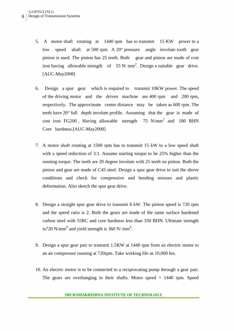
12. Referring figure: 1, spur gear A receives 3KW @ 600rpm through its shaft and
rotates clockwise. Gear B is an idler and C is the driven gear. The teeth are 20
degree full depth. Determine: (i) the torque each shaft must transmit (ii) The tooth
load for which each gear must be designed (iii) The force applied to the idler shaft
as a result of the gear tooth load. [AUC-Dec 2004]
Helical Gear drive
1. Design a pair of helical gears to transmit 25KW at a speed reduction ratio of 5:1.
The input shaft runs at 2000rpm.
2. A helical gear with 30 degree helix angle has to transmit 35kW at 1500 rpm with a
speed reduction ratio 2:5. If the pinion has 24 teeth determine the necessary
module, pitch diameter and face width for 20 degree full depth teeth. Assume
15Ni 2Cr 1 Mo15 material for both pinion and wheel.
3. Design a HELICAL gear drive to transmit 5 KW at 1440 rpm. Desired speed ratio
is 2.5. Take helix angle as 15°. Use C45 steel for the gears. Check for strength of
materials under different modes of failure. Make a clear sketch showing
important values of parameters. [AUT-Dec2010]
www.vidyarthiplus.com
GOPINATH.G
SRIT,CBE
10 Design of Transmission Systems
Veltech Hightech Dr.Rangarajan Dr.Sakunthala Engg College. Avadi
4. A pair of helical gear subjected to moderate shock loading is to transmit 20KW at
1500 rpm of the pinion. The speed reduction ratio is 4 and the helix angle is 20°.
The service is continuous and the teeth are 20°full depth in the normal plane. For
the gear life of 10,000 hours, design the gear drive. [AUC: Dec 2010]
5. Design a pair of helical gears to transmit 30KW power at a speed
reduction ratio of 4:1. The input shaft rotates at 2000 rpm. Take helix angle and
normal pressure angles equal 25° and 20° respectively. Both pinion and gear
are made of steel .The number of teeth on the pinion may be taken as
30. [AUC-May2008]
Name of the part Permissible stress BHN
Pinion 55MPa 340
Gear 40MPa 300
6. A pair of helical gears with 23º helix angel is to transmit 2.5 KW at 1000 rpm of
the pinion. The velocity ratio is 4: 1. The pinion is to be forged steel and the
driven gear is to be cast steel. The gears are of 20º full depth involute form and
the pinion is to have 24 teeth. Deign the gear drive.
7. A pair of helical gears is used to transmit 5 KW at 720 rpm of the pinion. Gears
are of made of C45 steel. The speed reduction ratio is 2. Number of teeth on
pinion is 20. Normal pressure angle is 20º. Normal module is 5mm. helix angle is
30º. Design the gear drive. (Use Lewis and Buckingham’s equation)
8. A helical gear with 30° helix angle has to transmit 35kW at 1500 rpm. With a
speed reduction ratio 2.5. If the pinion has 24 teeth, determine the necessary
module, pitch diameter and face width for 20° full depths the teeth. Assume
15Ni 2Cr 1 Mo 15 material for both pinion and wheel.
www.vidyarthiplus.com
GOPINATH.G
SRI RAMAKRISHNA INSTITUTE OF TECHNOLOGY,COIMBATORE
T.V.B.Babu ME(CAD/CAM)
Department of Mechanical Engineering
11
Veltech Hightech Dr.Rangarajan Dr.Sakunthala Engg College. Avadi
9. Design a pair of helical gears to transmit 30KW at a speed reduction ratio of 4:1.
The input shaft runs at 2000rpm. Both pinion and gear are 15Ni2Cr1 Mo 15 under
carburized condition.
UNIT-IIIBEVEL, WORM AND CROSS HELICAL GEARS
Straight bevel gear: Tooth terminology, tooth forces and stresses, equivalent number of
teeth. Estimating the dimensions of pair of straight bevel gears.
Worm Gear: Merits and demerits- terminology. Thermal capacity, materials-forces and
stresses, efficiency, estimating the size of the worm gear pair.
Cross helical: Terminology-helix angles-Estimating the size of the pair of cross helical
gears.
PART-A
Bevel Gear Drives
1. State the use of bevel gears. [AUC-May 2008]
2. When bevel gears are used? [AUC-May 2007]
3. Define: Miter gear & Crown gear.
4. Define: cone distance & face angle
5. What is virtual number of teeth in bevel gears? [AUC-A2004]
6. State true or false and justify. [AUC-D2005]
“Miter gears are used for connecting non-intersecting shafts”
7. What are zero bevel gears?
8. What are the forces acting on bevel gears?
9. What is reference angle? How is it related to speed ratio of bevel gear ratio?
[AUT-Dec2010]
10. If the radial force component of the bevel gear is 1200N (+ y direction), determine
the axial component of the pinion in the gear drive. Also write down the relation
between axial force and tangential force component. [AUC: Dec 2010]
Worm Gear
1. Where do we use worm gears?
2. What are commonly used materials for worm and wheel? [AUC-May 2007]
3. Name the different applications of worm Gear. [AUC-May2007]
www.vidyarthiplus.com
GOPINATH.G
SRIT,CBE
12 Design of Transmission Systems
Veltech Hightech Dr.Rangarajan Dr.Sakunthala Engg College. Avadi
4. Why the efficiency of worm gear drive is comparatively low? [AUC-A2004]
5. When the number of start of a worm is increased in a worm gear drive, how it
affects the other parameters and action of the drive? [AUC-A2004]
6. Usually worm is made of harder material & worm gear is made of softer material-
Justify.
7. In which gear drive, self – locking is available?
8. Why multi start worm more efficient than the single start one? [AUC-D2005]
9. What is irreversibility in worm gears?
10. Mention the reasons for irreversibility in worm gears. [AUC: Dec 2010]
11. State the advantage of worm gear drive in weight lifting machines. [AUC-May08]
12. How can you specify a pair of worm gear?
13. List out the main types of failure in worm gears.
14. What are the various losses in worm gear?
15. A pair of worm gears is designated as 2/54/10/5. Find the gear ratio.[AUC: Dec 2010]
Skew Gear
1. State the purpose of crossed helical gears. [AUT-Dec2010]
2. Where do we use skew gear?
3. Why the crossed helical gear drive not used for power transmission?[AUC-
D2007]
4. Calculate the angle between the shafts of a crossed helical gears made of two right
handed helical gears of 15° helix angle each. [AUC-May 2009]
PART-B
Bevel Gear Drive
1. Design the teeth of a pair of bevel gears to transmit 18.75 kW at 600 rpm of the
pinion. The velocity ratio should be about 3 and the pinion should have about 20
teeth which are full depth 20o involutes. Find the module, face width, diameter of
the gears and pitch core angle for both gears. [AUC-2007]
www.vidyarthiplus.com
GOPINATH.G
SRI RAMAKRISHNA INSTITUTE OF TECHNOLOGY,COIMBATORE
T.V.B.Babu ME(CAD/CAM)
Department of Mechanical Engineering
13
Veltech Hightech Dr.Rangarajan Dr.Sakunthala Engg College. Avadi
2. Design a pair of bevel gears for two shafts whose axes are at right angles to
transmit 20KW @ 1000 rpm. The speed of gear is 250rpm.
3. Design a BEVEL gear drive to transmit 4 KW. Speed ratio = 4. Driving shaft
speed 225 rpm. The drive is non-reversible. Assume a life of 25000 hours. [AUT-
Dec2010]
4. A Pair of bevel gears is to be used to transmit 14KW from a pinion rotating at
400rpm to a gear mounted on shaft running at 200rpm. The axes of the two shafts
are at 90°. Design the pair of bevel gears. .[AUC-May2008]
5. Design a pair of bevel gears for two shafts whose axes are at right angles to
transmit 10KW @ 1440 rpm. The speed of gear is 720rpm. Use Lewis &
Buckingham’s equation.
6. Design a pair of bevel gears to transmit 10 KW at a pinion speed of 1440 rpm.
Required transmission ratio is 4. Materials for gears is 15 Ni 2Cr 1 Mo 15.
7. Design a cast iron bevel gear drive for a pillar drilling machine to transmit
1.5KW at 800 rpm to a spindle at 400 rpm. The gear is to work for 40 hours per
week for 3 years. Pressure angle is 20°. Check the design and calculate the basic
dimensions. [AUC: Dec 2010]
8. A pair of straight tooth bevel gears has a velocity ratio of 4/3. The pitch diameter
of the pinion is 150 mm. The face width is 50mm. The pinion rotates at 240
rev/min. The teeth are 5mm module, 14 10 involutes. If 6 kW is transmitted,
determine (i) the tangential force at the Mean radius (ii) the pinion thrust force
(iii) the gear thrust force. Draw the free body diagrams indicating the forces.
[AUC-A2005]
9. Design a straight bevel gear drive between two shafts at right angles to each other.
Speed of the pinion shaft is 360 rpm and speed of the gear wheel shaft is 120 rpm.
www.vidyarthiplus.com
GOPINATH.G
SRIT,CBE
14 Design of Transmission Systems
Veltech Hightech Dr.Rangarajan Dr.Sakunthala Engg College. Avadi
Pinion is of steel and wheel of cast iron. Each gear is expected to work 2 hours/
day for 10 years. The drive transmits 9.37 KW.
10. A 1 kW motor running at 1200 rpm drives a compressor at 780 rpm through a 90o
bevel gearing arrangement. The pinion has 30 teeth. The pressure angle of the
teeth is 20o. Both the pinion and gear are made of heat treated cast iron grade 35.
Determine the cone distance, average module and face width of the gears.
Worm and Wheel Drive
11. Design worm gear drive to transmit 50KW @ 1440 rpm. Velocity ratio is 24.
12. A hardened steel WORM rotates at 1440 rpm and transmits 12 KW to a phosphor
bronze gear with gear ratio of 16. Design the worm gear drive and determine the
power loss by heat generation. [AUT-Dec2010]
13. Design a worm gear drive to transmit 15 KW form a worm at 1440 rpm to the
worm wheel. The speed of the worm wheel should be 40±2% rpm.
14. A hardened steel worm rotates at 1440 rpm and transmits 12KW to a phosphor
bronze gear. The speed of the worm wheel should be 60±3%rpm. Design the
worm gear drive if an efficiency of at least 82% is desired. [AUC: Dec 2010]
15. Design a worm gear drive to transmit a power of 22.5 KW. The worm speed is
1440 rpm and the speed of the wheel is 60 rpm. The drive should have a minimum
efficiency of 80% and above. Select suitable materials for the worm and the wheel
and decide upon the dimensions of the drive.
16. A 2 kW power is applied to a worm shaft at 720 rpm. The worm is of quadruple
start with 50mm as pitch circle diameter. The worm is of quadruple start type with
50mm as pitch circle diameter. The worm gear has 40 teeth with 5mm module.
The pressure angle in the diametral plane is 20°. Determine (i) the lead angle of
the worm, (ii) velocity ratio, and (ii) centre distance. Also, calculate efficiency of
the worm gear drive, and power lost in friction.
www.vidyarthiplus.com
GOPINATH.G
T.V.B.Babu ME(CAD/CAM)
Department of Mechanical Engineering
15
Veltech Hightech Dr.Rangarajan Dr.Sakunthala Engg College. Avadi
17. Design a worm gear drive to transmit 22.5 kW at a worm speed of 1440 rpm.
Velocity ratio is 24:1. An efficiency of at least 85% is desired. The temperature
rise should be restricted to 40o C. Determine the required cooling area
UNIT-IVDESIGN OF GEAR BOXES
Geometric progression - Standard step ratio - Ray diagram, kinematics layout -Design of
sliding mesh gear box -Constant mesh gear box. – Design of multi speed gear box.
PART-A
1. What you mean by ray diagram in multi speed gear box?
2. Draw the ray diagram for a six speed gear box. [AUC-May2007]
3. What is step ratio? Name the series in which speeds of multi-speed gear box are
arranged.
4. Give some applications of constant mesh gear box. [AUC-May 2007]
5. What is step ratio? [AUT-Dec2010]
6. Why G.P. series is selected for arranging the speeds? [AUT-Dec2010]
7. What is the function of spacers in gear box?
8. Draw the ray diagram for a 14 speed gear box.
9. List six standard speeds starting from 18 rpm with a step ratio 1.4.
10. Sketch the kinematics layout of gears for 3 speeds between two shafts.
11. What are preferred numbers?
12. List any two methods used for changing speeds in gear box.
13. What situation demands the use of gear box?
14. State any three basic rules followed in designing a gear box
15. What are the possible arrangements to achieve 16 speeds from a gear box? Which
is the preferred arrangement? [AUC: Dec 2010]
16. What does the ray diagram of gear box indicates? [AUC: Dec 2010]
www.vidyarthiplus.com
GOPINATH.G
SRIT,CBE
16 Design of Transmission Systems
Veltech Hightech Dr.Rangarajan Dr.Sakunthala Engg College. Avadi
17. Explain why the discrete speeds are specified in geometric series for any
machine tools. [AUC-May2008]
PART-B
1. A six speed gear box is required to provide output speeds in the range of 125
to 400 rpm with a step ratio of 1.25 and transmit a power of 5 kW at 710 rpm.
Draw the speed diagram and kinematics diagram. Determine the number of
teeth module and face width of all gears, assuming suitable materials for the
gears.
2. Design a 9 speed gear box for the following data. Minimum speed: 100rpm,
step ratio: 1.25. The input is from a 4KW, 1440rpm motor. Draw the speed
diagram, kinematic diagram and indicate the number of teeth on each gear.
3. Design a nine – speed gear box for a machine to provide speeds ranging from
100 to 1500 rpm. The input is from a motor of 5 kW at 1440 rpm. Assume any
alloy steel for the gear.
4. A machine tool gear box is to have 9 speeds. The gear box is driven by an
electric motor whose shaft rotational speed is 1400 rpm. The gear box is
connected to the motor by a belt drive. The maximum and minimum speeds
required at the gear box output are 1000 rpm and 200 rpm respectively.
Suitable speed reduction can also be provided in the belt drive. What is the
step ratio and what are the values of 9 speeds? Sketch the arrangement. Obtain
the number of teeth on each gear and also the actual output speeds.
5. Select speeds for a 12 speed gear box for a minimum speed of 16 rpm and a
maximum speed of 900rpm. Draw the speed diagram, kinematic diagram and
indicate the number of teeth on each gear.
6. Design the layout of a 12 speed gear box for a milling machine having an
output of speeds ranging from 180 to 2000 rpm. Power is applied to the gear
box from a 6 kW induction motor at 1440 rpm. Choose standard step ratio and
www.vidyarthiplus.com
GOPINATH.G
SRI RAMAKRISHNA INSTITUTE OF TECHNOLOGY,COIMBATORE
T.V.B.Babu ME(CAD/CAM)
Department of Mechanical Engineering
17
Veltech Hightech Dr.Rangarajan Dr.Sakunthala Engg College. Avadi
construct the speed diagram. Decide upon the various reduction ratios and
number of teeth on each gear wheel sketch the arrangement of the gear box.
[AUC-May2008]
7. Design the headstock gear box of a lathe having nine spindle speeds ranging
from 25 to 1000 rpm. The power of the machine may be taken as 6 kW and
speed of the motor is 1450 rpm. Minimum number of teeth on the gear is to
be 25. a) Draw the speed diagram b) Sketch the layout of the gear box.
c) Calculate the number of teeth on all gears.
8. A gear box is to be designed for the following specifications:
Power to be transmitted = 5.5KWNumber of speeds = 9Minimum speed = 280 rpmMaximum speed = 1800 rpmInput motor speed = 1440 rpm
Draw the kinematic layout diagram and the speed diagram. Determine the
number of teeth on all gears. [AUC: Dec 2010]
9. Draw the ray diagram and kinematic lay out of a gear box for an all geared
headstock of a lathe. The maximum and minimum speeds are to be 600 and 23
rpm respectively. The number of steps is 12 and drive is from a 3 kW electric
motor running at 1440rpm.
10. Select speeds for a 12 speed GEAR BOX for a minimum speed of 112 rpm
and maximum speed of 1400 rpm. Drive speed is 1400 rpm. Draw speed
diagram and a kinematic arrangement of the gear box showing the number of
teeth in all the gears. [AUT-Dec2010]
11. The spindle of a pillar drill is to run at 12 different speeds in the range of
100rpm and 135 rpm. Design a three stage gear box with a standard step ratio.
The gear box receives 5KW from an electric motor running at 360rpm. Sketch
the layout of the gear box, indicating the number of teeth on each gear. Also
sketch the speed diagram. [AUC: Dec 2010, May2008]
www.vidyarthiplus.com
GOPINATH.G
SRIT,CBE
18 Design of Transmission Systems
Veltech Hightech Dr.Rangarajan Dr.Sakunthala Engg College. Avadi
12. Design a 16 speed gear box for the following data. Minimum speed: 100rpm,
step ratio: 1.25. The input is from a 5KW, 1000rpm motor. Draw the speed
diagram, kinematic diagram and indicate the number of teeth on each gear
13. In a milling machine, 18 different speeds in the range of 35 rpm and 650 rpm
are required. Design a three stage gear box with a standard step ratio. Sketch
the layout of the gear box, indicating the number of teeth on each gear. The
gear box receives 3.6 kW from an electric motor running at 1440 rpm. Sketch
also the speed diagram.
14. For a load lifting arrangement transmitting 7.5 KW with electric motor
running at 1440 rpm, constant mesh type SPEED REDUCER is required with
reduction ratio 16. Design a suitable arrangement and make a neat sketch.
[AUT-Dec2010]
UNIT-VDESIGN OF CAM, CLUTCHES AND BRAKES
Cam Design: Types-pressure angle and under cutting base circle determination-forces and surface stresses.
Design of plate clutches –axial clutches-cone clutches-internal expanding rim clutches-internal and external shoe brakes
PART-A
Clutches
1. What is the function of a clutch?
2. What is the use of clutch in power transmission systems? [AUC-May2007]
3. Classify clutches based on the coupling methods. [AUC-D2004]
4. List the advavantages and applications of multi-plate clutch.
5. What is the difference between a clutch and coupling?
6. Name four materials used for lining of friction surfaces in clutches. Write the
desirable properties of lining materials.[AUC-M2005]
7. How the “uniform rate of wear” assumption is valid for clutches?
8. Why should the temperature rise be kept within the permissible range in clutch?
9. Sketch a cone clutch.
www.vidyarthiplus.com
GOPINATH.G
SRIT,COIMBATORE
T.V.B.Babu ME(CAD/CAM)
Department of Mechanical Engineering
19
Veltech Hightech Dr.Rangarajan Dr.Sakunthala Engg College. Avadi
10. What are the desirable properties of friction material to be used for clutches?
Brakes
11. What is fading of brakes? [AUC-D2004]
12. What is meant by self-locking brakes?
13. What is meant by a self – energizing brake? [AUC-D2005]
14. Why in automobiles braking action when travelling in reverse is not aseffective as when moving forward? [AUC-May2008]
15. Give the reason for left and right shoes of internal expansion brakes having
different actuating forces. [AUC-May 2007]
16. How does the function of a brake differ from that of a clutch? [AUT-Dec2010]
17. List the characteristics of material used for brake lining. [AUC: Dec 2010]
Cam
18. What is the function of a cam?
19. What is undercutting in cams?
20. What are the different types of followers?
21. State the advantage of cam over other reciprocating mechanisms.
22. What is the significance of pressure angle in cam design?
23. What is jerk? Name the profile of the cam that gives no jerk. [AUT-Dec2010]
24. Define base circle and pitch circle with respect to cam. [AUC: Dec 2010]
PART-B
Plate Clutches
1. A single plate sketch, effective on both sides, is required to transmit 25 KW at
3000 rpm. Determine the outer and inner diameter of frictional surfaces if the
coefficient of friction is 0.25, ratio of diameter is 1.25 and the maximum pressure
is not to exceed 0.1 N/mm2. Determine (i) the face width required and (ii) the
axial spring force necessary to engage the clutch. [AUT-Dec2010]
2. A dry single plate clutch is to be designed for an automotive vehicle whose engine
is rated to give 100KW at 2400 rpm and maximum torque 500 N-m. The outer
radius of the friction plate is 25% more than the inner radius. The intensity of
pressure between the plates is not to exceed 0.07 N/mm2. The coefficient of
friction may be assumed to be equal to 0.3. The helical springs are required by this
www.vidyarthiplus.com
GOPINATH.G
SRIT,CBE
20 Design of Transmission Systems
Veltech Hightech Dr.Rangarajan Dr.Sakunthala Engg College. Avadi
clutch to provide axial force necessary to engage the clutch are 8. If each spring
has a stiffness of 40N/mm, determine the dimensions of the friction plate and
initial compression in the springs. [AUC-A2005]
3. A plate clutch with maximum diameter 60mm has maximum lining pressure of
0.35 MPa. The power to be transmitted at 400 rpm is 135 KW and µ= 0.3. Find
inside diameter and spring force required to engage the clutch. Springs with spring
index 6 and material spring steel with safe shear stress 600 MPa are used. Find the
diameters if 6 springs are used. [AUT-Dec 2004]
4. A single plate clutch, both side being effective is required to connect a machine
shaft to a driver shaft which runs at 500rpm .The moment of inertia of the rotating
parts of the machine is 1Kgm2.The inner and the outer radii of the friction discs
are 50mm&100mm respectively .Assuming uniform pressure of 0.1N/mm2 and
μ =0.25, determine the time taken for the machine to reach full speed when the
clutch is suddenly engaged. Also determine the power transmitted by the clutch,
the energy dissipated during the clutch slip and the energy supplied to the machine
during engagement.
Multi-plate Clutch
1. A multi disk clutch consists of five steel plates and four bronze plates. The inner
and outer diameters of friction disks are 75mm and 150mm respectively. The
coefficient of friction is 0.1 and the intensity of pressure is limited to 0.3. N/mm2.
Assuming the uniform wear theory, calculate (i) the required operating force, and
(ii) power transmitting capacity at 750 rpm. [AUC: May-2008]
2. A plate clutch has 3 discs on the driving shaft and 2 discs on the driven shaft,
providing 4 pairs of contact surfaces. The OD of contact surface is 240mm and ID
is 120mm. Assuming uniform pressure and µ=0.3, find the total spring load for
pressing the plates together to transmit 25KW @ 1575 rpm. If there are 6 springs
each of stiffness 13KN/m and each of contact surfaces have worn away by
1.25mm, find the power that can be transmitted, assuming uniform wear. [AUC-
May 2007]
www.vidyarthiplus.com
GOPINATH.G
SRIT,COIMBATORE
T.V.B.Babu ME(CAD/CAM)
Department of Mechanical Engineering
21
Veltech Hightech Dr.Rangarajan Dr.Sakunthala Engg College. Avadi
3. A multi disc wet clutch is to be designed for a machine tool driven by an electric
motor of 12.5 KW running at 1440 rpm. Space restrictions limit the outside disc
diameter to 100mm. Determine the appropriate value of inside diameter, total
number of discs and clamping force. [AUC-A2004]
4. A hydraulically operated clutch is to be designed for an automatic lathe.
Determine the number of plates and operating force required for the clutch to
transmit 35 Nm. The clutch is to be designed to slip under 300% of rated torsional
moment to protect the gears and other part of the drive. The limits for the diameter
of friction surfaces due to space limitation are 100mm and 62.5mm. This clutch is
to operate in an oily atmosphere.[AUC-Dec 2005]
Cone Clutches
1. An engine developing 45kW at 1000 rpm id fitted with a cone clutch built inside
the fly wheel. The cone has a face angle of 12.5 degree and a maximum mean
diameter of 500 mm. The coefficient of friction is 0.2. The normal pressure on the
clutch face is not exceeded 0.1N/mm 2. Determine (i) The face width required (ii)
the axial spring force necessary to engage the clutch.
2. A cone clutch has a cone angle of 11.5o, a mean frictional diameter of 320 mm,
and face width of 60 mm. The clutch is to transmit a torque of 200 Nm. The
coefficient of friction is 0.26. Find the activating force and pressure using the
assumption of uniform pressure.
3. A power of 20 KW is to be transmitted through a cone clutch at 500rpm. For
uniform wear condition, find the main dimensions of the clutch and shaft. Also
determine the axial force required to engage the clutch. Assume the coefficient of
friction as 0.25, the maximum normal pressure on the friction surface is not to
exceed 0.08 MPa and take the design stress for the shaft material as 40MPa.
4. A cone clutch is to transmit 7.5KW at 900rpm. The cone has a face angle of 12o.
The width of the face is half of the mean radius and the normal pressure between
www.vidyarthiplus.com
GOPINATH.G
SRIT,CBE
22 Design of Transmission Systems
Veltech Hightech Dr.Rangarajan Dr.Sakunthala Engg College. Avadi
the contact faces is not to exceed 0.9 N/mm2. Assuming uniform wear and the
coefficient of friction between contact faces as 0.2, find the main dimensions of
the clutch and the axial force required to engage the clutch. [AUC-Dec2010]
5. A leather faced conical clutch has cone angle of 30 degree. The pressure between
the contact surfaces is limited to 0.35N/mm2 and breadth of the conical surface is
not to exceed 1/3 of the mean radius. Find the dimensions of the contact surfaces
to transmit 22KW at 2000rpm. Also calculate the force required to engage the
clutch. Take coefficient of friction as 0.15.
6. A power of 20 KW is to be transmitted through a cone clutch at 500 rpm. For
uniform wear condition find the main dimensions of the clutch and shaft. Also
determine the axial force required to engage the clutch. Assume the coefficient of
friction as 0.25, the maximum normal pressure on the friction surface is not to
exceed 0.08 MPa and take the design stress for the shaft material as 40 MPa.
[AUT-May2006]
Brakes
Single block brake
1. A single block brake, the diameter of drum is 250mm and the angle of contact is
90o. The operating force of 700N is applied at the end of lever which is at 250mm
from the centre of the brake block. Determine the torque that may be transmitted.
Fulcrum is at 200mm from the centre of brake block with an offset of 50mm from
the surface of contact. The coefficient of friction is 0.35 [AUC-May 2007]
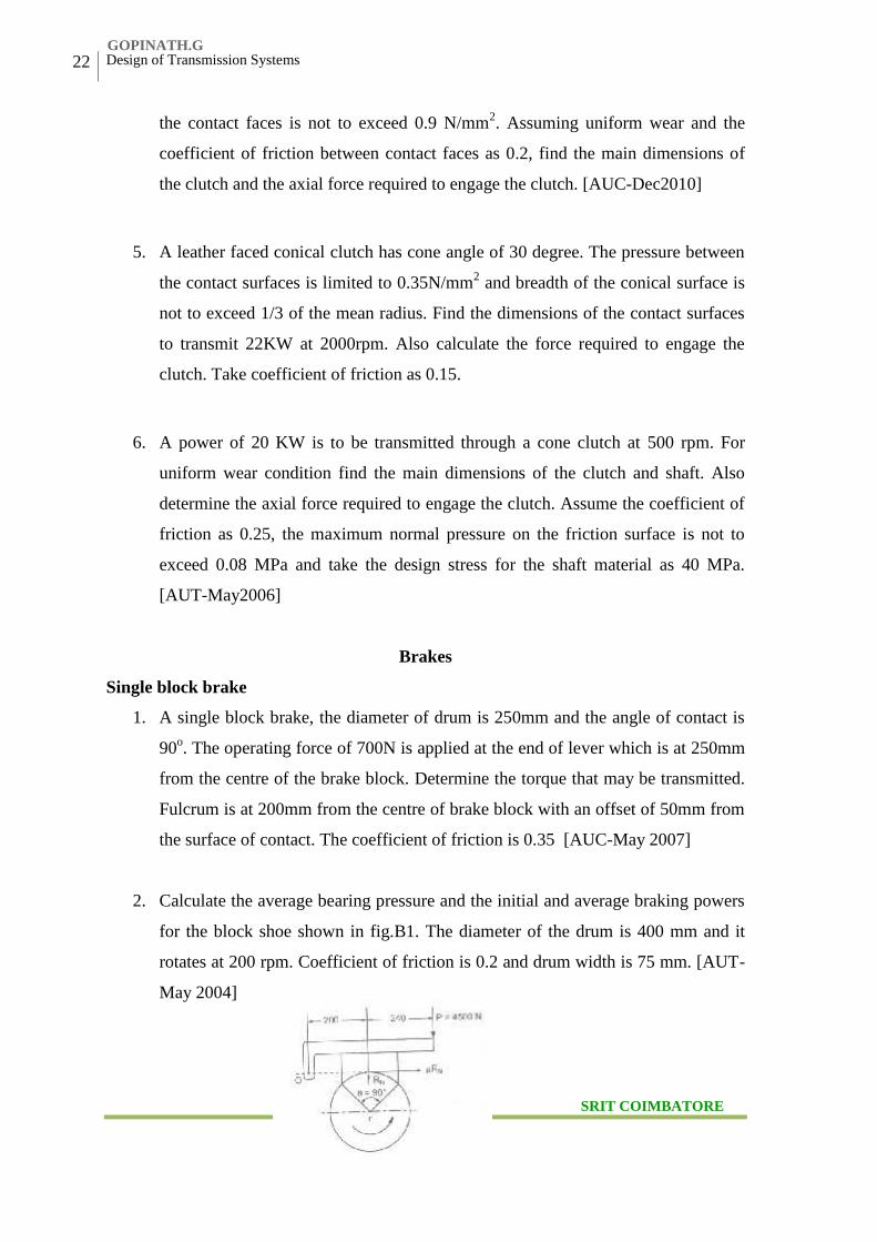
2. Calculate the average bearing pressure and the initial and average braking powers
for the block shoe shown in fig.B1. The diameter of the drum is 400 mm and it
rotates at 200 rpm. Coefficient of friction is 0.2 and drum width is 75 mm. [AUT-
May 2004]
www.vidyarthiplus.com
GOPINATH.G
SRIT COIMBATORE

T.V.B.Babu ME(CAD/CAM)
Department of Mechanical Engineering
23
Veltech Hightech Dr.Rangarajan Dr.Sakunthala Engg College. Avadi
Figure: B1
3. A 360 mm radius Brake drum contacts a single shoe as shown in figure (B2) and
resists a torque of 250 Nm at 500 rpm. The co-efficient of friction is 0.3.
determine
(i) The normal reaction on the shoe,
(ii) The force to be applied at the lever end for counter clockwise rotation of the
drum if e= 0
(iii) The force to be applied at the lever end for clockwise rotation of the drum if
e= 42 mm.
(iv) The force to be applied at the lever end for counter clockwise rotation of the
drum if e = 42 mm. [AUT-Dec2010]
Figure: B2
Double block brake
4. A rope drum of an elevator having 650mm diameter is fitted with a brake drum of
1m diameter. The brake drum is provided with 4 cast iron brake shoes each
subtending an angle of 45o .The mass of elevator when loaded is 200Kg and
moves with a speed of 2.5m/s. The brake has sufficient capacity to stop the
elevator in 2.75m. Assuming the coefficient of friction as 0.2, find (i) Width of
shoe if the allowable pressure on the brake shoe is limited to 0.3 N/mm2. (ii) Heat
generated in stopping the elevator. [AUC-A 2005]
www.vidyarthiplus.com
GOPINATH.G
SRIT,CBE
24 Design of Transmission Systems
Veltech Hightech Dr.Rangarajan Dr.Sakunthala Engg College. Avadi
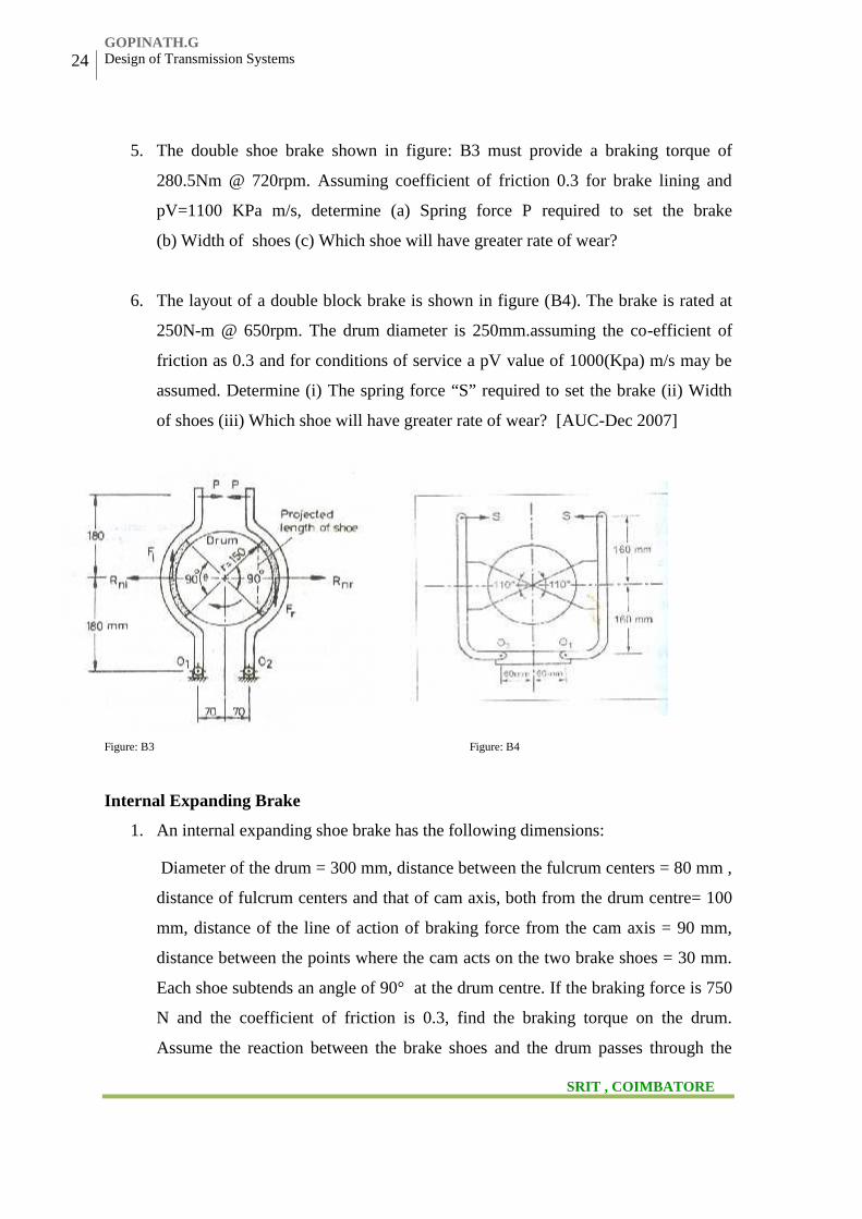
5. The double shoe brake shown in figure: B3 must provide a braking torque of
280.5Nm @ 720rpm. Assuming coefficient of friction 0.3 for brake lining and
pV=1100 KPa m/s, determine (a) Spring force P required to set the brake
(b) Width of shoes (c) Which shoe will have greater rate of wear?
6. The layout of a double block brake is shown in figure (B4). The brake is rated at
250N-m @ 650rpm. The drum diameter is 250mm.assuming the co-efficient of
friction as 0.3 and for conditions of service a pV value of 1000(Kpa) m/s may be
assumed. Determine (i) The spring force “S” required to set the brake (ii) Width
of shoes (iii) Which shoe will have greater rate of wear? [AUC-Dec 2007]
Figure: B3 Figure: B4
Internal Expanding Brake
1. An internal expanding shoe brake has the following dimensions:
Diameter of the drum = 300 mm, distance between the fulcrum centers = 80 mm ,
distance of fulcrum centers and that of cam axis, both from the drum centre= 100
mm, distance of the line of action of braking force from the cam axis = 90 mm,
distance between the points where the cam acts on the two brake shoes = 30 mm.
Each shoe subtends an angle of 90° at the drum centre. If the braking force is 750
N and the coefficient of friction is 0.3, find the braking torque on the drum.
Assume the reaction between the brake shoes and the drum passes through the
www.vidyarthiplus.com
GOPINATH.G
SRIT , COIMBATORE
T.V.B.Babu ME(CAD/CAM)
Department of Mechanical Engineering
25
Veltech Hightech Dr.Rangarajan Dr.Sakunthala Engg College. Avadi
point bisects the contact angle. Also assume that forces exerted by the cam ends
on the two shoes are equal. [AUC-Dec 2009]
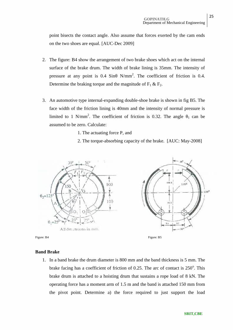
2. The figure: B4 show the arrangement of two brake shoes which act on the internal
surface of the brake drum. The width of brake lining is 35mm. The intensity of
pressure at any point is 0.4 Sinθ N/mm2. The coefficient of friction is 0.4.
Determine the braking torque and the magnitude of F1 & F2.
3. An automotive type internal-expanding double-shoe brake is shown in fig B5. The
face width of the friction lining is 40mm and the intensity of normal pressure is
limited to 1 N/mm2. The coefficient of friction is 0.32. The angle θ1 can be
assumed to be zero. Calculate:
1. The actuating force P, and
2. The torque-absorbing capacity of the brake. [AUC: May-2008]
Figure: B4 Figure: B5
Band Brake
1. In a band brake the drum diameter is 800 mm and the band thickness is 5 mm. The
brake facing has a coefficient of friction of 0.25. The arc of contact is 250o. This
brake drum is attached to a hoisting drum that sustains a rope load of 8 kN. The
operating force has a moment arm of 1.5 m and the band is attached 150 mm from
the pivot point. Determine a) the force required to just support the load
www.vidyarthiplus.com
GOPINATH.G
SRIT,CBE
26 Design of Transmission Systems
Veltech Hightech Dr.Rangarajan Dr.Sakunthala Engg College. Avadi
b) the required force when the direction is reversed, and c) the width of steel band,
limiting its tensile strength to 50 N/mm2.
2. Design a differential band brake for a winch lifting a load of 20KN through a steel
rope wound round a barrel of 600mm diameter. The brake drum, keyed to the
barrel shaft, is of 800mm diameter and the angle of lap of the band over the drum
is about 240o. Operating arm of the brake are 50mm and 250mm. Length of
operating lever is 1.6m. Also calculate the effort applied. [AUC-May 2006]
3. Design a differential band brake for a winch lifting a load of 20KN through a steel
rope wound round a barrel of 600mm diameter. The brake drum, keyed to the
barrel shaft, is of 800mm diameter and the angle of lap of the band over the drum
is about 240o. Operating arm of the brake are 50mm and 250mm. Length of
operating lever is 1.5m. Also calculate the effort applied.
4. A differential band brake is to be designed for a winch lifting a load of 45KN
through a rope wound round a barrel of 500mm diameter. The brake drum, (to be
keyed to the barrel shaft, is to be 600mm diameter and the angle of lap of the band
over the drum is 250o. Determine the width and thickness of band. Operating arm
of the brake are 40mm and 200mm. Length of operating lever is 1.5m. Also
calculate the effort applied.[AUC-A2004]
Band & Block Brake
5. Determine the maximum braking torque for a band and block brake having 12
blocks, each of which subtends an angle of 16o at the centre. The brake is applied
to a rotating drum of diameter 600mm. The blocks are 75mm thick. The two ends
of bands are attached to a pin on the opposite sides of the brake fulcrum at
distances 40mm and 150mm from the fulcrum. A force of 250N is applies at a
distance of 900mm from the fulcrum.
Design of Cam
www.vidyarthiplus.com
GOPINATH.G
SRIT , COIMBATORE

T.V.B.Babu ME(CAD/CAM)
Department of Mechanical Engineering
27
Veltech Hightech Dr.Rangarajan Dr.Sakunthala Engg College. Avadi
6. Draw the displace time , velocity time and the acceleration time curves for the
follower in order to satisfy the following conditions (1) Stroke of the follower
25mm (2) Outstroke takes place with SHM during 900 of cam rotation (3) Return
stroke takes with SHM during 750 of cam rotation (4) Cam rotates with a uniform
speed of 800 rpm. [AUT-April 2010]
7. A cam is to give the following motion to a knife-edged follower :[AUC-Dec2010]
Outstroke during 60o of cam rotation;
Dwell for the next 30o of cam rotation;
Return stroke during next 60o of cam rotation and
Dwell for the remaining 210o of cam rotation. The stroke of the follower is 40mm
and the minimum radius of the cam is 50mm. the follower moves with uniform
velocity during both the outstroke and return strokes. Draw the profile of the cam
when the axis of the follower passes through the axis of the cam shaft.
8. A radial cam rotates at 1200 rpm with the follower rising 20mm with SHM in
1500 of the cam rotation .The roller is 32mm in diameter and the prime circle is
80mm in diameter. Check whether undercutting will occur.
9. A cycloidal cam with a central roller follower has a rise of 25mm in cam angle of
70o. Base circle radius is 90mm and the follower roller radius is 20mm. Speed of
cam is 5000rpm. Mass of follower is 0.5Kg. Find the maximum value of
acceleration of the follower, corresponding pressure angle, stiffness of the spring
used with the follower and maximum cam force. The friction between the
follower and the guide may be ignored. [AUC- Dec2007]
10. Design a cam for operating the exhaust valve of an oil engine. It is required to
give equal uniform acceleration and retardation during opening and closing of the
valve, each of which corresponding to 60° of cam rotation. The valve should
remain in the fully open position for 20° of cam rotation. The lift of the valve is
37.5 mm and the least radius of the cam is 50 mm, the follower is provided with a
roller of 50 mm diameter and its line of stroke passes through the axis of the cam.
[AUC- 2009]
www.vidyarthiplus.com
GOPINATH.G
SRIT,COIMBATORE


![MPHIL APPROVED GUIDE DETAILS [COLLEGE WISE] 1.College … · MPHIL APPROVED GUIDE DETAILS [COLLEGE WISE] 6 Dr.M.Malathi Asst.Prof. Computer Science 04.01.2011 7 Mrs.D.Chitra Asst.Prof](https://img.pdfslide.us/doc/110x75/5f81a86bec52c522f360768d/mphil-approved-guide-details-college-wise-1college-mphil-approved-guide-details.jpg)