Embed Size (px)
Citation preview

EasyChair Preprint№ 5781
Associate Intensification Approach in the JetEngine Burner
Siddhant Pandey and Dharmahinder Singh Chand
EasyChair preprints are intended for rapiddissemination of research results and areintegrated with the rest of EasyChair.
June 12, 2021

1
ASSOCIATE INTENSIFICATION APPROACH IN
THE JET ENGINE BURNER Siddhant Pandey1, Dharmahinder Singh Chand2
1. Research Scholar, Mechanical Engg., Chandigarh University Mohali, Punjab 140310,
India.
2. Professor, Aerospace Engg., Chandigarh University, Mohali, Punjab 140310, India.
Abstract
Burning is one of the indispensable interactions in
the power age framework as is the combustor in a
Gas Turbine. The per-execution of combustor
greatly affects the proficiency of the cycle,
subsequently, combustor has consistently been on
the prime concentration for scientists to improve
the effectiveness of gas turbines. This paper
presents the improvement of the ignition chamber
proficiency inferable from blending by changing
the fuel outlet cross-area i.e., by keeping it square,
pentagon, and hexagon. Estimations of centerline
speed comparing Mach number 0.2. to 0.35, and
comparative estimations were done for all cross-
part of fuel infusion outlet at Mach number
0.2,0.25,0.35,0.35 for square, pentagon, and
hexagon. The efficiency for square is
51.81%,56.46%,56.52%,57.31% and for pentagon
58.52%,59.13%,60.1%,61% and lastly for hexagon
is 53.4%,60.795%,61.889%, 62.8% respectively. It
was found that maximum efficiency was achieved
by employing a hexagon cross-section of the
injector since it has several contact points with the
incoming air, which in turn enhances the mixing
property.
Keywords: -combustion chamber, fuel injector, Mach
number etc.
1. Introduction
The majority of modern commercial and military
aircraft are powered by gas turbine engines, also
known as jet engines. Gas turbine motors come in
a variety of shapes and sizes, but they always
have a few key components in common. Every
turbine motor has a combustor, or burner, where
the fuel is mixed with high-pressure air and
consumed. Air enters the front entrance and is
compressed in the basic jet engine. The air is then
forced into burning chambers, where fuel is
sprinkled on top, and the mixture of air and fuel is
ignited. The gases that create immediately
develop and are swiftly exhausted as they pass
through the back of the burning chambers. As
they break to the back, these gases exert equal
power in all directions, providing a forward thrust.
As the gases exit the motor, they pass through a
turbine, which is a fan-like arrangement of sharp
edges that turns a shaft known as the turbine shaft.
As a result, this shaft pivots the blower, allowing
a new supply of air to enter the entrance.
Process describing working of Combustion
Chamber: -
• Suck: - Through the fan and blower
stages, the engine takes in a large amount
of air. During takeoff, a typical
commercial jet engine takes in 1.2 tons
of air every second. A portion of the
pressure stage is usually the instrument
by which a fly motor sucks noticeable all
around. The blower is responsible for
both drawing in and compacting air in
many engines.

2
• Squeeze: - In addition to supplying air to
the motor, the blower compresses the air
and transports it to the burning chamber.
A shaft drives the pressure fans from the
turbine (the turbine is thus determined by
the air that is leaving the motor).
Blowers can achieve pressure
proportions of more than 40:1, implying
that the air pressing factor toward the
blower's end is more than 40 times that
of the air entering the blower.
• Bang: - Fuel is mixed with air in the
burning chamber to create the bang,
which is responsible for the extension
that drives the air into the turbine. The
ignition chamber has the difficult task of
copying massive amounts of fuel,
delivered via fuel shower spouts, with
large volumes of air, delivered via the
blower, and delivering the resulting
warmth in such a way that the air is
extended and speeded up to provide a
smooth stream of consistently warmed
gas. This task should be refined with the
least amount of pressure loss and the
greatest amount of heat discharge
possible within the limited space
available.
• Blow: The expanded gas—a mixture of
fuel and air—is confined by the turbine,
which drives the fan and blower and
smothers the fumes spout, providing
thrust.
(Fig 1.1 Sectional view of a jet engine)
(Fig 1.2 Schematic diagram of a jet engine)
Types of Combustion Chamber: -
• Can: The most punctual airplane engines
utilized can (or rounded) combustors. Air
leaving the blower is parted into various
separate streams, each providing a different
chamber. These loads are dispersed around the
shaft interfacing the blower and turbine, each
chamber having its fuel fly took care of from a
typical stock line. Appropriate to motors with
divergent blowers, where the stream is isolated
into independent streams in the diffuser.
• Cannular: A plan in which fire tubes are spread
out inside the packaging, bringing about weight
decrease and a simplicity of-development
advantage. The inventory of optional air to the
fire tubes is made through a typical air
packaging while essential air for burning is
provided through singular air admissions.
• Annular: The ideal setup as far as reduced
measurements are the annular combustor, in
which most extreme use is made of the space
accessible inside a determined distance across;
this ought to decrease the pressing factor
misfortune and results in a motor of least
breadth. The ignition doesn't occur in individual
flame tubes, yet rather in an annular locale
around the engine.

3
Fuel Injector:
A fuel injector is an electronically controlled
mechanical device that infuses/splashes (much like
a needle) fuel into the engine for the preparation of
the proper air-fuel mixture, resulting in efficient
engine combustion. Pressure-atomizing, air impact,
disintegrating, and premix/vaporizing injectors are
the four basic types of fuel injectors.
Mixing:
Jet Engines use fuel and air to deliver energy
through ignition. To ensure the burning interaction,
certain amounts of fuel and air should be provided
in the ignition chamber. A total ignition happens
when all the fuel is singed, in the exhaust gas there
will be no amounts of unburned fuel. There are
different types of fuel mixtures such as
Stoichiometric mixture(the kind of air-fuel blend
in which measure of air is barely enough to finish
burning of fuel), Rich air-fuel mixture(this sort of
combination contains the measure of air not
exactly the measure of air present in the
stoichiometric blend, the blend has abundance
fuel) and Lean air-fuel mixture(in this the air-
fuel blend which has the more air than the
stoichiometric prerequisite, the lean blend is more
effective than a stoichiometric combination).
Liquid fuel injection:
The main purpose of fuel injection is to prepare a
fuel-air mixture suitable for the combustion
process. The injection helps in the complete
burning of fuel thereby decreasing the emission of
NO and CO which increases the efficiency of an
engine.
S.no Type Diagram Construction
1
Can
• Initial designs
• Low Cost /
Development
• Robust
2
Cannular
• Low
Development
Cost
• Inter-Connector
3
Annular
• Clean
Aerodynamics
• Compact
• High
Development
Cost

4
(Fig 1.3 Schematic diagram for liquid fuel injection in
C.C)
Primary Zone where the mainstream of the oil
ignition incomes dwelling
Intermediate Region is the air vaccinated hooked on
the combustion region through the additional set of
lining cells
Dilution Region is airflow vaccinated done dumps
in the facing at the end of the combustion
compartment
Fuel Spray Nozzle is rummage-sale to provide
improved mixing of the oil and airflow to provide an
optimum spray for combustion.
Atomization: Atomization refers to the procedure of
breaking up bulk liquids into droplets.
(Fig 1.4 Schematic diagram of atomization)
2. LITERATURE REVIEW
Some authors have completed experimental and
simulation studies on combustion mixing to increase
the performance of the engine. Some
procedures/methods are revealed below:
FlamesF. Hamppa, b et al [1]
Hydrogen-upgraded fuel blends, for instance, syngas,
offer phenomenal potential in the decarburization of
gas turbine progress by substitution and advancement
of the lean working cutoff. It is shown that CH4
hinderingly affects the reaction study of H2. The
creators infer that scaling associations can give
reasonable plan tests to decide the properties of the
hydrogen progressed fuel blend.
Michael Seibert et al [2]
Hydrogen conveys equivalent benefits to
unadulterated advantages when given as a component
of a "reformer petroleum" mix. Tests utilized JP-8 and
either hydrogen or packaged blazes to test the
temperature profiles of double shot flares. Burning is
pushed before from every single strengthening fuel,
making more steady and diminished size potential. To
support fuel energy admission at a consistent stage,
the-8 stream rate was diminished to 5.5 kW.

5
R. W. SCHAEFER et al [3]
Spin, using 45-degree whirl vanes, was applied to the
stream. The consumption occurred at barometrical
load inside an air-cooled quartz chamber. Assessments
of the gas test have had the chance to show diminishes
in CO obsession with hydrogen. Near the slight
adequacy limit, the fire structure Direct splendid
pictures and planar laser impelled fluorescence
assessments have been perceived. The reformist OH.
Results prescribe that the development to the
methane/air blend of a moderate proportion of
hydrogen.
M. Saediamiri et al [4]
Nonprefixed biogas fire determination was
presumably centered around fluctuating the fuel
Composition and CO2 and changing the math of fuel
spouts. The fuel was conveyed through an encased
focal spout. A co-focus breeze current that encounters
a generator of low-turn (25-point vanes). The
terminations showed that the goals of the bio as fire
adequacy are particularly delicate to the design of the
fuel. It widened the legitimacy of this relationship by
having all turning blasts that are non-premixed and
premixed.
Zouhaier Riahi et al [5]
In air ignition, nitrogen creates low burning yields and
high energy utilization. The expansion of hydrogen to
flammable gas, Combustion implies an ascent in the
temperature of the adiabatic fire. Improves the
steadiness of the fire, builds CO2 outflows, diminishes
the arrangement of CO, however, favors NOx, as
indicated by research in the diary Chemiluminescence.
The discoveries show that oxygen and hydrogen are
added and hydrogen goes from 0 to 15 percent, says
the examination. It further builds the attributes of auto-
start and the worldwide warmth discharge rate.
K.K.J. Ranga Dinesh et al [6]
Fire features of spinning non-premixed H2/CO syngas
fuel blends were emulated. The combustor design
picked is the TECFLAM burner. Diffusivity of
hydrogen in H2-rich fuel is responsible for the
creation of significantly thicker fire in a spinning fire.
The appraisals for H2 and CO-rich bursts show huge
assortments among speed and CO-rich flares.
M.A. Mergheni et al [7]
Paper inspects the effect of the proportionality extent
on no prefixed characteristics'- methane fire with
disconnected planes from a burner. The 25-kW power
burner is made out of Three synchronized planes, a
lone central stream of methane enveloped by two
planes of oxygen. To think about the collaboration of
unevenness reaction, the twirl dissipating model is
applied. The examination was coordinated with
various extents of overall likeness (0.7, 0.8, and 1).
Zakaria Mansouria et al [8]
The Kelvin-Helmholtz feebleness provoked ring
structures and the spinning flimsiness started finger
structures. The spinning plane by then ends up being
mature, with a 222 Hz influencing repeat. The stream
in the district of offal complex direct, including an
appropriation area, incorporates an injector. At the
burner leave, the 3D stream structure, Vortex risks are
the essential ones.
R. Paulauskasa et al [9]
A permeable plate burner with dielectric obstacle
discharge was used for plasma-helped, premixed start.
Nanosecond high-voltage beat drove miniature
plasmas at 3 kHz and 10 kHz emphasis rates in the
burner openings. The biogas fire security has
improved during plasma-helped start. The plasma
sway was diminished and the departure was reduced
by only 3810% at 10 kHz discharge and by just 3810
percent. With 3 kHz discharge, 227%. The
assessments with designed air improved with oxygen
showed that the oxygen noticeable all around was not
of superior grade.
Kurji el at [10]
Syngas or biodiesel can be utilized to meet gas turbine
working expenses. The utilization of combinations of
biodiesel and CO2/CH4 mixes brought about lower
CO creation, that is, 87% lower at 10% CO2 for the
circumstance. Results showed that a critical decline in
NOx of ~ 50% was accomplished in all Conditions for
mixes of biodiesel/CO2/CH4. The fuel is at first either
fluid or strong. Decides patterns in NOx and CO
discharges. At various equivalences, a correlation
between the mixes was completed Proportions.
Ahmed E.E. Khalil et al [11]
Drab Distributed Combustion (CDC) has shown up.
CDC rules fuse the controlled bunch of hot responsive
species to outline a low gathering of oxygen from
inside the combustor. Contrasting the obtained data
Liquid forces and vaporous fills have demonstrated
that the unavoidable CDC can be settled at the oxygen
obsession, paying little brain to the fuel used. The mix
temperature inside the extent of 0.75%.
M.S. Irandoost n et al [12]
Micromixers were proposed for oxy-fuel consumption
in zero-surge power plants. Miniature blender gas-
turbine advancement joined with hydrogen headway to
add oxy-fuel burner for use in the Allah power zero-
release. Propelling the hydrogen fuel was found to
help fire proficiency, which considered dropping the
oxygen division further down to a record-low gauge of
13% at a 65 percent hydrogen segment. This makes
the cycle's turndown and low-load capacities fantastic
strategic flexibility and leading improvement, says the
investigation. The discoveries additionally uncovered
that the progression of hydrogen marginally affects
fire temperature, besides, combustor strength thickness

6
(power per unit volume) in changing the hydrogen part
to work with fire adequacy.
Muzafar Hussain et al [13]
Miniature blenders are thusly the development
proposed for oxy-fuel consumption in zero-outpouring
power plants. Propelling the fuel with hydrogen was
found to help fire reliability, which considered
diminishing the oxygen division further down to a
record-low assessment of 13% at a hydrogen part of
65% (by vol.) This offers staggering operational
flexibility and leading improvement in the turndown
and low-load capacities of the cycle, the examination
found. The results in like manner showed that
hydrogen progression insignificantly affects fire
temperature, also, combustor power thickness.
Chinonso Ezenwajiaku et al [14]
Polycyclic fragrant hydrocarbons (PAHs) are the
disease-causing sections of debris. This investigation
presents a preliminary method to separate PAH
improvement characteristics of a non-premixed
methane-air fire with and without hydrogen (H2)
extension. PAH fluorescence power outperforms were
seen to increase with extending height over the burner,
in any case, this speed of addition diminished with H2
extension. The proposed exploratory technique for
PAH assessments can be quickly applied to any fuel
mixes.
E. Distasoa et al [15]
The creator's reason that CH4 brings about a more
grounded obstructing sway on the reaction study of
H2compared to H2. The use of hydrogen-progressed
fuel blends, for instance, syngas, offers exceptional
potential in the decarburization of gas turbine propels,
they say. The reason that scaling associations can
outfit reasonable simultaneousness with the trial of
hydrogen fuel blends.
Zhichao Chen a,b et al [16]
A three-fragment particle components anemometer is
used to check, in the nearby burner area, the qualities
of gas/atom two-stage streams with a halfway fuel-rich
spin coal start burner likewise, overhauled start
twofold register burner. Rates, RMS speeds, atom
mean distances across, and particle volume progress
profiles were gotten. For the midway fuel-rich burner,
particles penetrate the central appropriation zone not
completely and are then redirected radially.
Alejandro M. Briones et al [17]
The effects of H2 enhancement for the spread of
laminar CH4–air triple blasts in axisymmetric
coflowing planes are numerically investigated. An
expansive, time-subordinate computational model is
used to reenact the transient light and fire-causing
wonders. The fire design and fire components are
extraordinarily changed by the H2 upgrade, which
liberally fabricates the fire curve and mix division
point. The H2 development also changes the fire
affectability to stretch out, as it lessens the Mark stein
number (Ma), gathering an extended tendency toward
diffusive–warm feebleness.
T. Boushakia,b et al [18]
This paper presents an assessment of the powerful
characteristics of non-premixed savage whirling blasts
using the sound framework PIV technique. The results
explain one expected segment for the reduction of the
NOx spreads when the overall proportionality extent
increases utilizing an extension of the entrainment rate
at the firebase. The outcomes show that the presence
of the fire impels a greater twisting stream
advancement, higher mean velocities, and higher
unevenness powers. It is furthermore demonstrated
that the differences of the digressive speed are for the
most part obligated for the most important unevenness
dynamic energy levels at the most noteworthy mark of
the central appropriation zone.
Mohamed Mahdi et al [19]
This paper presents a numerical assessment of a
burner of 25 kW power. It surveys the effect of
hydrogen on the components, the dispersal of
temperature, the sufficiency of the fire, the assortment
of species mass part (CO, CO2. . .), and the radiative
warmth change. Results show that the extension of
hydrogen extensively influences dynamic direct and
fire temperature. The use of hydrogen-progressed fuel
blends, for instance, syngas, offers exceptional
potential in the decarbonization of gas turbine propels,
the creators say. The creators infer that CH4 brings
about a more grounded frustrating effect on the
reaction study of H2compared to H2. The reason that
scaling associations can outfit reasonable
simultaneousness with a trial of hydrogen fuel blends
in a back-to-burned-through repudiated stream
arrangement.
Semiha Oztuna et al [20]
In the current assessment, the effects of hydrogen
progression of methane are investigated numerically
from the scattering fire construction and surges
perspective. Recognizable code is utilized as the
reenactment gadget. Four tests were driven using
petrol gas as fuel. The results show that the hydrogen
development to methane in a general sense changes
the spread fire structure in the start chamber. The
hydrogen-progressed flares become more broad and
more restricted to respect to the unadulterated methane

7
fire. The most limit temperature regard is resolved as
2030 K for the case with a 15% hydrogen
development extent by mass.
Objective: -
1. Mixing improvement by shifting infusion
outlet cross-area.
2. Incrementing burning effectiveness.
3. Reduction in explicit fuel burning.
1. Methodology
4.1 For Square Cross section:
(Fig 4.1 total temperature at Mach 0.35)
(Fig 4.1 total velocity at Mach 0.35)
Ansys 18.1
Module(fluent flow)
Geometry Selection
Mesh Generation
Set Up
Solution
Result

8
Sr.no Mach
numbe
r
Inlet
Pressur
e (bar)
of Fuel
Outlet
Shape
of
Fuel
Outlet
Efficienc
y (%)
1 0.20 3 Square 58.24
2 0.20 4 Square 57.20
3 0.20 5 Square 56.64
4 0.20 6 Square 56.6437
5 0.20 7 Square 51.81
6 0.25 3 Square 6.30
7 0.25 4 Square 58.25
8 0.25 5 Square 57.18
9 0.25 6 Square 56.71
10 0.25 7 Square 56.46
11 0.30 3 Square 6.76
12 0.30 4 Square 7.0
13 0.30 5 Square 58.30
14 0.30 6 Square 57.27
15 0.30 7 Square 56.52
16 0.35 3 Square 7.35
17 0.35 4 Square 7.96
18 0.35 5 Square 8.1
19 0.35 6 Square 58.24
20 0.35 7 Square 57.316
(Table 4.1 Efficiency of a Square)
4.2 For Pentagon Cross-section
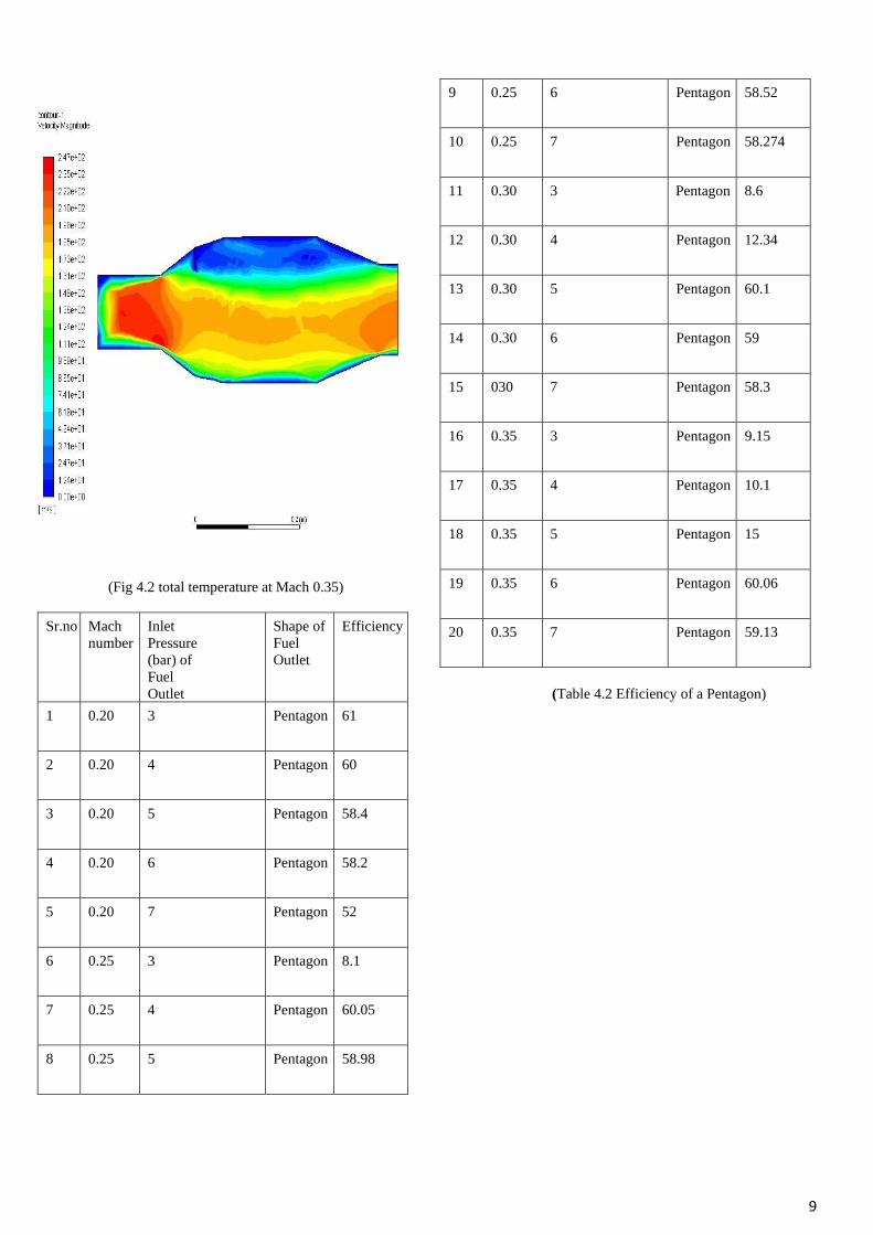
(Fig 4.2 total temperature at Mach 0.35)
9
(Fig 4.2 total temperature at Mach 0.35)
Sr.no Mach
number
Inlet
Pressure
(bar) of
Fuel
Outlet
Shape of
Fuel
Outlet
Efficiency
1 0.20 3 Pentagon 61
2 0.20 4 Pentagon 60
3 0.20 5 Pentagon 58.4
4 0.20 6 Pentagon 58.2
5 0.20 7 Pentagon 52
6 0.25 3 Pentagon 8.1
7 0.25 4 Pentagon 60.05
8 0.25 5 Pentagon 58.98
9 0.25 6 Pentagon 58.52
10 0.25 7 Pentagon 58.274
11 0.30 3 Pentagon 8.6
12 0.30 4 Pentagon 12.34
13 0.30 5 Pentagon 60.1
14 0.30 6 Pentagon 59
15 030 7 Pentagon 58.3
16 0.35 3 Pentagon 9.15
17 0.35 4 Pentagon 10.1
18 0.35 5 Pentagon 15
19 0.35 6 Pentagon 60.06
20 0.35 7 Pentagon 59.13
(Table 4.2 Efficiency of a Pentagon)

10
4.3 For the Hexagon Cross-section
(Fig 4.3 total temperature at Mach 0.35)
(Fig 4.3 total velocity at Mach 0.35)
Sr.no Mach
number
Inlet
Pressure
(bar) of
Fuel
Outlet
Shape of
Fuel
Outlet
Efficiency
1 0.20 3 Hexagon 62.8
2 0.20 4 Hexagon 60.8
3 0.20 5 Hexagon 60.22
4 0.20 6 Hexagon 60.15
5 0.20 7 Hexagon 53.4
6 0.25 3 Hexagon 9.88
7 0.25 4 Hexagon 61.889
8 0.25 5 Hexagon 60.795
9 0.25 6 Hexagon 60.33
10 0.25 7 Hexagon 60.1
11 0.30 3 Hexagon 10.39
12 0.30 4 Hexagon 12.11
13 0.30 5 Hexagon 61.9
14 0.30 6 Hexagon 60.85
15 0.30 7 Hexagon 60.16
16 0.35 3 Hexagon 10.94
17 0.35 4 Hexagon 11
18 0.35 5 Hexagon 23

11
19 0.35 6 Hexagon 61.84
20 0.35 7 Hexagon 60.93
(Fig 4.3 Efficiency of Hexagon)
2. Result
In fig 5.1 it is seen that at Mach 0.20 square
efficiency is invariant while changing the
pressure 3 to 7 bar at Mach number 0.20 its
sudden decreases at Mach 0.25 pressure 3 bar
after that it increases its efficiency at pressure
(bar) 4 to 7 at Mach 0.3 and bars 3 and 4
efficiency sudden decreases as we increase
pressure with same Mach number, also efficiency
increases 5 to 7 (bar) at Mach 0.35 and at pressure
3 to 5 efficiency invariant as it increases at
pressure 6,7.
In case of the pentagon at Mach 0.20 to 0.35 the
efficiency increases 8% to 61% here no
efficiency reduction is found while increasing
Mach number. In the case of the hexagon at Mach
0.25 minimum efficiency 9.88% to 62.8% it
increases to Mach 0.25 then suddenly reduced at
Mach 0.30,0.35 after it will again increases, in
pentagon there is maximum fuel mixing at mid-
zone beyond that swirling form due to incomplete
combustion takes place. It has five contact
mixing on the other hand hexagon has six
contacts of mixing to get complete fuel
combustion less unburnt fuel is remaining to get
efficiency 61.84% at Mach 0.35.
(Fig 5.1 Efficiency Comparisons)
Sr.n
o
Mach
numb
er
Pressu
re
(bar)
Hexago
n
Efficien
cy (%)
Squar
e
Efficie
ncy
(%)
Pentago
n
Efficien
cy (%)
1 0.20 3 62.8 58.24 61
2 0.20 4 61.8 57.2 60
3 0.20 5 60.22 56.64 58.4
4 0.20 6 60.15 56.6437 58.2
5 0.20 7 53.4 51.81 52
6 0.25 3 9.88 6.3 8.1
7 0.25 4 61.889 58.25 60.05
8 0.25 5 60.795 57.18 58.98
9 0.25 6 60.33 56.71 58.52
10 0.25 7 60.1 56.46 58.274
11 0.30 3 10.39 6.76 8.6
12 0.30 4 11.12 7 9
13 0.30
5 61.9 58.3 60.1
14 0.30 6 60.85 57.27 59
15 0.30 7 60.16 56.52 58.3
16 0.35 3 10.92 7.35 9.15
17 0.35 4 11 7.96 10
18 0.35 5 23 8.1 15
19 0.35 6 61.84 58.24 60.06
0
0.05
0.1
0.15
0.2
0.25
0.3
0.35
0.4
0 2 0 4 0 6 0 8 0
MA
CH
NU
MB
ER
EFFICIENCY
Hexagon Square Pentagon

12
20 0.35 7 60.93 57.316 59.13
(Table 5.1 Efficiency Comparison)
(Fig 5.2 Maximum Efficiency of Square Type Fuel
Injector)
(Fig 5.3 Maximum Efficiency of Pentagon Type
Fuel Injector)
(Fig 5.4 Maximum Efficiency of Hexagon Type Fuel
Injector)
3. Conclusion
The results of the present investigation
demonstrate that the mixing caused by the hexagon
is superior to the identical cross-section of
pentagon and square. The mixing promoting
efficiency is increased with increase in Mach
number. It is found that among the hexagon is a
better mixing promoter, that provides better
efficiency less emission of unburnt fuel to reduce
the impact of environmental pollution.
4. Future Scope
• It is recommended Mach number less
than 0.35 use Hexagon type fuel injection
for better efficiency for jet engine.
• It is recommended Mach number more
than 0.35 use Pentagon type fuel injection
for better efficiency for jet engine.
• Further studies and experimental
investigations should be conducted to
improve the efficiency of a jet engine,
especially in the fields of combustion
mixing, fuel injection, and afterburner.
58.24
58.25
58.3
58.24
58.23
58.24
58.25
58.26
58.27
58.28
58.29
58.3
58.31
0 0.1 0.2 0.3 0.4
Eff
icie
ncy
Mach Number
Square Efficiency
61
60.0560.1 60.06
59.8
60
60.2
60.4
60.6
60.8
61
61.2
0 0.1 0.2 0.3 0.4
Eff
icie
ncy
Mach Number
Pentagon Efficiency
62.8
61.889 61.961.84
61.6
61.8
62
62.2
62.4
62.6
62.8
63
0 0.1 0.2 0.3 0.4
Eff
icie
ncy
Mach Number
Hexagon Efficiency

13
7.References
[1] F. Hampp, K. H. H. Goh, and R. P.
Lindstedt, “The reactivity of hydrogen
enriched turbulent flames,” Process Saf.
Environ. Prot., vol. 143, pp. 66–75, 2020.
[2] M. Gadaleta, G. Berselli, M. Pellicciari, and
M. Sposato, “A Simulation Tool for
Computing Energy Optimal Motion
Parameters of Industrial Robots,” Procedia
Manuf., vol. 11, no. June, pp. 319–328,
2017.
[3] R. W. Schefer, D. M. Wicksall, and A. K.
Agrawal, “Combustion of hydrogen-
enriched methane in a lean premixed swirl-
stabilized burner,” Proc. Combust.
Inst., vol. 29, no. 1, pp. 843–851, 2002.
[4] M. Saediamiri, M. Birouk, and J. A.
Kozinski, “Flame stability limits of low
swirl burner − Effect of fuel composition
and burner geometry,” Fuel, vol. 208, pp.
410– 422, 2017.
[5] Z. Riahi, M. A. Mergheni, J. C. Sautet, and
S. Ben Nasrallah, “Experimental study of
natural gas flame enriched by hydrogen and
oxygen in a coaxial burner,” Appl. Therm.
Eng., vol. 108, pp. 287–295, 2016.
[6] K. K. J. Ranga Dinesh, K. H. Luo, M. P.
Kirkpatrick, and W. Malalasekera,
“Burning syngas in a high swirl burner:
Effects of fuel composition,” Int. J.
Hydrogen Energy, vol. 38, no. 21, pp.
9028–9042, 2013.
[7] M. A. Mergheni, T. Boushaki, J. C. Sautet,
and S. Ben Nasrallah, “Numerical study of
oxy-flame characteristics in a burner with
three separated jets,” Appl.
Therm. Eng., vol. 111, pp. 1–7, 2017.
[8] Z. Mansouri and T. Boushaki,
“Experimental and numerical investigation
of turbulent isothermal and reacting flows
in a non-premixed swirl burner,” Int. J.
Heat Fluid Flow, vol. 72, no. June, pp.
200–213, 2018.
[9] R. Paulauskas et al., “Biogas combustion
with various oxidizers in a nanosecond
DBD microplasma burner,” Exp. Therm.
Fluid Sci., vol. 118, no. May, 2020.
[10] H. Kurji, A. Valera-Medina, A. Okon, and
C. T. Chong, “Combustion and emission
performance of CO2/CH4/biodiesel and
CO2/CH4/diesel blends in a Swirl Burner
Generator,” Energy Procedia, vol. 142, pp.
154–159, 2017.
[11] A. E. E. Khalil and A. K. Gupta, “Fostering
distributed combustion in a swirl burner
using prevaporized liquid fuels,” Appl.
Energy, vol. 211, no. July 2017, pp.
513–522, 2018.
[12] M. S. Irandoost, M. Ashjaee, M. H. Askari,
and S. Ahmadi, “Temperature measurement
of axisymmetric partially premixed
methane/air flame in a co- annular burner
using Mach-Zehnder interferometry,” Opt.
Lasers Eng., vol. 74, pp.
94–102, 2015.
[13] M. Hussain, A. Abdelhafez, M. A.
Nemitallah, A. A. Araoye, R. Ben-Mansour,
and M. A. Habib, “A highly diluted oxy-
fuel micromixer combustor with hydrogen
enrichment for enhancing turndown in gas
turbines,” Appl. Energy, vol. 279, no.
September, p. 115818, 2020.
[14] C. Ezenwajiaku, M. Talibi, N. A. K. Doan,
N. Swaminathan, and R. Balachandran,
“Study of polycyclic aromatic
hydrocarbons (PAHs) in hydrogen-enriched
methane diffusion flames,” Int. J. Hydrogen
Energy, vol. 44, no. 14, pp. 7642– 7655,
2019.
[15] E. Distaso, R. Amirante, P. Tamburrano,
and R. D. Reitz, “Understanding the role of
soot oxidation in gasoline combustion: A
numerical study on the effects of oxygen
enrichment on particulate mass and number
emissions in a spark-ignition engine,”
Energy Convers. Manag., vol. 184, no.
January, pp. 24–39, 2019.
[16] Z. Chen, Z. Li, J. Jing, L. Chen, S. Wu, and
Y. Yao, “Gas/particle flow characteristics
of two swirl burners,” Energy Convers.
Manag., vol. 50, no. 5, pp.
1180–1191.
[17] A. M. Briones, S. K. Aggarwal, and V. R.
Katta, “Effects of H2 enrichment on the
propagation characteristics of CH4-air triple

14
flames,” Combust. Flame, vol. 153, no. 3,
pp. 367–383, 2008.
[18] T. Boushaki, N. Merlo, S. de Persis, C.
Chauveau, and I. Gökalp, “Experimental
investigation of CH4-air-O2 turbulent
swirling flames by Stereo-PIV,” Exp.
Therm. Fluid Sci., vol. 106, no. April, pp.
87–99, 2019.
[19] M. M. Belhaj Brahim, M. A. Mergheni, N.
Ben Khedher, S. Ben Nasrallah, and J.
C. Sautet, “Numerical study of hydrogen
enrichment effects in oxy-flame turbulent
of three separated jets,” Appl. Therm. Eng.,
vol. 113, pp. 490–498, 2017.
[20] S. Öztuna and M. K. Büyükakın, “Effects of
hydrogen enrichment of methane on
diffusion flame structure and emissions in a
back-pressure combustion chamber,” Int. J.
Hydrogen Energy, vol. 45, no. 10, pp.
5971–5986, 2020.