Embed Size (px)
Citation preview
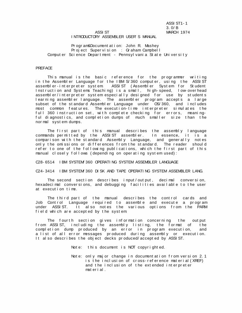
ASSIST1-1 3.0/B ASSIST MARCH 1974 INTRODUCTORY ASSEMBLER USER'S MANUAL Program&Documentation: John R. Mashey Project Supervision : Graham Campbell Computer Science Department - Pennsylvania State University PREFACE This manual is the basic reference for the programmer writing in the Assembler Language for the IBM S/360 computer, using the ASSIST assembler-interpreter system. ASSIST (Assembler System for Student Instruction and Systems Teaching) is a small, high-speed, low-overhead assembler/interpreter system especially designed for use by students learning assembler language. The assembler program accepts a large subset of the standard Assembler Language under OS/360, and includes most common features. The execution-time interpreter simulates the full 360 instruction set, with complete checking for errors, meaning- ful diagnostics, and completion dumps of much smaller size than the normal system dumps. The first part of this manual describes the assembly language commands permitted by the ASSIST assembler. In essence, it is a comparison with the standard Assembly Language, and generally notes only the omissions or differences from the standard. The reader should refer to one of the following publications, which the first part of this manual closely follows (depending on operating system used): C28-6514 IBM SYSTEM/360 OPERATING SYSTEM ASSEMBLER LANGUAGE C24-3414 IBM SYSTEM/360 DISK AND TAPE OPERATING SYSTEM ASSEMBLER LANG. The second section describes input/output, decimal conversion, hexadecimal conversions, and debugging facilities available to the user at execution time. The third part of the manual describes the control cards and Job Control Language required to assemble and execute a program under ASSIST. It also notes the various options from the PARM field which are accepted by the system. The fourth section gives information concerning the output from ASSIST, including the assembly listing, the format of the completion dump produced by an error in program execution, and a list of all error messages produced during assembly or execution. It also describes the object decks produced/accepted by ASSIST. Note: this document is NOT copyrighted. Note: only major change in documentation from version 2.1 is the inclusion of cross-reference material(XREF) and the inclusion of the extended interpreter material.
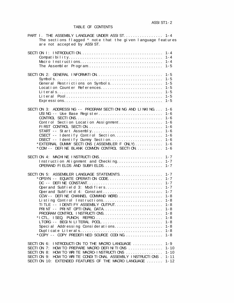
ASSIST1-2 TABLE OF CONTENTS PART I. THE ASSEMBLY LANGUAGE UNDER ASSIST................. 1-4 The sections flagged * note that the given language features are not accepted by ASSIST. SECTION I: INTRODUCTION.................................... 1-4 Compatibility......................................... 1-4 Macro Instructions.................................... 1-4 The Assembler Program................................. 1-5 SECTION 2: GENERAL INFORMATION............................. 1-5 Symbols............................................... 1-5 General Restrictions on Symbols....................... 1-5 Location Counter References........................... 1-5 Literals.............................................. 1-5 Literal Pool.......................................... 1-5 Expressions........................................... 1-5 SECTION 3: ADDRESSING -- PROGRAM SECTIONING AND LINKING.... 1-6 USING -- Use Base Register............................ 1-6 CONTROL SECTIONS...................................... 1-6 Control Section Location Assignment................... 1-6 FIRST CONTROL SECTION................................. 1-6 START -- Start Assembly............................... 1-6 CSECT -- Identify Control Section..................... 1-6 DSECT -- Identify Dummy Section....................... 1-6 *EXTERNAL DUMMY SECTIONS (ASSEMBLER F ONLY)............ 1-6 *COM -- DEFINE BLANK COMMON CONTROL SECTION............ 1-6 SECTION 4: MACHINE INSTRUCTIONS............................ 1-7 Instruction Alignment and Checking.................... 1-7 OPERAND FIELDS AND SUBFIELDS.......................... 1-7 SECTION 5: ASSEMBLER LANGUAGE STATEMENTS................... 1-7 *OPSYN -- EQUATE OPERATION CODE........................ 1-7 DC -- DEFINE CONSTANT................................. 1-7 Operand Subfield 3: Modifiers......................... 1-7 Operand Subfield 4: Constant.......................... 1-7 CCW -- DEFINE CHANNEL COMMAND WORD.................... 1-8 Listing Control Instructions.......................... 1-8 TITLE -- IDENTIFY ASSEMBLY OUTPUT..................... 1-8 PRINT -- PRINT OPTIONAL DATA.......................... 1-8 PROGRAM CONTROL INSTRUCTIONS.......................... 1-8 *ICTL, ISEQ, PUNCH, REPRO.............................. 1-8 LTORG -- BEGIN LITERAL POOL........................... 1-8 Special Addressing Considerations..................... 1-8 Duplicate Literals.................................... 1-8 *COPY -- COPY PREDEFINED SOURCE CODING................. 1-8 SECTION 6: INTRODUCTION TO THE MACRO LANGUAGE ............. 1-9 SECTION 7: HOW TO PREPARE MACRO DEFINITIONS ............... 1-10 SECTION 8: HOW TO WRITE MACRO-INSTRUCTIONS ................ 1-10 SECTION 9: HOW TO WRITE CONDITIONAL ASSEMBLY INSTRUCTIONS . 1-11 SECTION 10: EXTENDED FEATURES OF THE MACRO LANGUAGE ....... 1-12
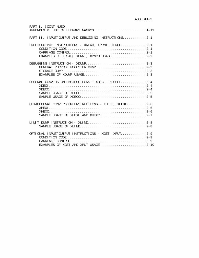
ASSIST1-3 PART I. (CONTINUED) APPENDIX K: USE OF LIBRARY MACROS.......................... 1-12 PART II. INPUT/OUTPUT AND DEBUGGING INSTRUCTIONS........... 2-1 INPUT/OUTPUT INSTRUCTIONS - XREAD, XPRNT, XPNCH............ 2-1 CONDITION CODE........................................ 2-1 CARRIAGE CONTROL...................................... 2-1 EXAMPLES OF XREAD, XPRNT, XPNCH USAGE................. 2-2 DEBUGGING INSTRUCTION - XDUMP.............................. 2-3 GENERAL PURPOSE REGISTER DUMP......................... 2-3 STORAGE DUMP.......................................... 2-3 EXAMPLES OF XDUMP USAGE............................... 2-3 DECIMAL CONVERSION INSTRUCTIONS - XDECI, XDECO............. 2-4 XDECI................................................. 2-4 XDECO................................................. 2-4 SAMPLE USAGE OF XDECI................................. 2-5 SAMPLE USAGE OF XDECO................................. 2-5 HEXADECIMAL CONVERSION INSTRUCTIONS - XHEXI, XHEXO......... 2-6 XHEXI................................................. 2-6 XHEXO................................................. 2-6 SAMPLE USAGE OF XHEXI AND XHEXO....................... 2-7 LIMIT DUMP INSTRUCTION - XLIMD............................. 2-8 SAMPLE USAGE OF XLIMD................................. 2-8 OPTIONAL INPUT/OUTPUT INSTRUCTIONS - XGET, XPUT............ 2-9 CONDITION CODE........................................ 2-9 CARRIAGE CONTROL...................................... 2-9 EXAMPLES OF XGET AND XPUT USAGE....................... 2-10

PART III. ASSIST CONTROL CARDS AND DECK SETUP.............. 3-1 A. JOB CONTROL LANGUAGE.................................... 3-1 B. OPTIONAL PARAMETERS FOR ASSIST.......................... 3-2 C. DESCRIPTION OF INDIVIDUAL OPTIONS....................... 3-4 PART IV. ASSIST OPTIONAL EXTENDED INTERPRETER.............. 4-1 A. GENERAL DESCRIPTION OF NEW FEATURES..................... 4-1 B. THE XOPC (Assist OPtions Call) DEBUGGING INSTRUCTION.... 4-2 PART V. OUTPUT AND ERROR MESSAGES......................... 5-1 A. ASSEMBLY LISTING........................................ 5-1 1. ASSEMBLY LISTING FORMAT............................ 5-1 2. ASSEMBLER ERROR MESSAGES........................... 5-1 3. LIST OF ASSEMBLER ERROR MESSAGES................... 5-2 4. ASSEMBLER STATISTICS SUMMARY....................... 5-10 B. ASSIST MONITOR MESSAGES................................. 5-11 1. HEADING AND STATISTICAL MESSAGES................... 5-11 2. ASSIST MONITOR ERROR MESSAGES...................... 5-12 C. ASSIST COMPLETION DUMP.................................. 5-13 D. COMPLETION CODES........................................ 5-14 E. OBJECT DECKS AND LOADER MESSAGES........................ 5-15 1. OBJECT DECK FORMAT................................. 5-15 2. ASSIST LOADER USAGE AND MESSAGES................... 5-16 PART I. THE ASSEMBLY LANGUAGE UNDER ASSIST This section deals with the subset of the standard OS/360 Assembler Language accepted be the ASSIST assembler. Because it follows the standard very closely, the following describes only those language features which ASSIST omits or treats differently. The user should generally consult the previously-mentioned publication for most of the information on the assembler language. The section headings and sub-headings in this manual are taken from the IBM publication, and any sections omitted may be assumed to be the same as the corresponding sections in the IBM manual. SECTION 1: INTRODUCTION Compatibility With a few possible exceptions, any program which assembles and executes correctly under ASSIST should do so using the standard OS/360 software, and should produce the same output as under ASSIST. At most, a change of Job Control Language might be necessary.

The Assembler Program The assembler program produces a listing of the source program, and normally creates an object program directly in main memory, while using no secondary storage, unless requested. An object deck can be punched. SECTION 2: GENERAL INFORMATION General Restrictions on Symbols A symbol may be defined only once in an assembly, i.e., it may appear in the name field of no more than one instruction. The same symbol may not be used as a label in two different control sections, and control sections may not be resumed, the only case in the standard language allowing the same symbol on more than one statement. Location Counter Reference ASSIST allows full use of the location counter *, with the following exceptions: 1. The programmer may not refer to the location counter inside a literal address constant. Thus, the following statement will produce incorrect results: L 1,=A(*+20) 2. The programmer may not refer to the location counter in an A-type address constant having a duplication factor greater than one, if the reference is made in such a way that the various duplications of the specified constant have different values. For instance, under OS/360, the following statement would produce the values 0,1,...,255, but ASSIST would produce 256 bytes of zero: NAME DC 256AL1(*-NAME) Literals Literal constants may not contain more than 112 characters, counting the beginning = and ending delimiter, i.e. may not require more than two cards when placed in the literal pool. Literal Pool Unless otherwise specified by the use of the LTORG instruction, the literal pool is placed after the program's END card, rather than at the end of the first control section in the program. Expressions Use of general expressions is permitted for most statements. Any restrictions are noted under the individual statements.
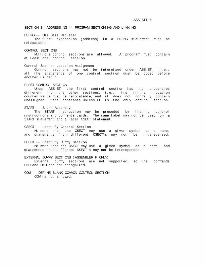
ASSIST1-6 SECTION 3: ADDRESSING -- PROGRAM SECTIONING AND LINKING USING -- Use Base Register The first expression (address) in a USING statement must be relocatable. CONTROL SECTIONS Multiple control sections are allowed. A program must contain at least one control section. Control Section Location Assignment Control sections may not be intermixed under ASSIST, i.e., all the statements of one control section must be coded before another is begun. FIRST CONTROL SECTION Under ASSIST, the first control section has no properties different from the other sections, i.e., its initial location counter value must be relocatable, and it does not normally contain unassigned literal constants unless it is the only control section. START -- Start Assembly The START instruction may be preceded by listing control instructions and comments cards. The same label may not be used on a START statement and a later CSECT statement. CSECT -- Identify Control Section No more than one CSECT may use a given symbol as a name, and statements from different CSECT's may not be interspersed. DSECT -- Identify Dummy Section No more than one DSECT may use a given symbol as a name, and statements from different DSECT's may not be interspersed. EXTERNAL DUMMY SECTIONS (ASSEMBLER F ONLY) External dummy sections are not supported, so the commands CXD and DXD are not recognized. COM -- DEFINE BLANK COMMON CONTROL SECTION COM is not allowed.

ASSIST1-7 SECTION 4: MACHINE-INSTRUCTIONS Instruction Alignment and Checking If any statement requires alignment and causes bytes to be skipped, the bytes skipped are NOT necessarily set to hexadecimal zeros. OPERAND FIELDS AND SUBFIELDS ASSIST permits the same use of expressions in machine-instruction operand fields as does the standard assembler. SECTION 5: ASSEMBLER LANGUAGE STATEMENTS OPSYN -- EQUATE OPERATION CODE is not accepted. DC -- DEFINE CONSTANT Multiple operands (up to 10 operands in a single DC statement) and multiple constants within operands are both permitted. Bytes skipped to align a DC statement are NOT zeroed. Operand Subfield 3: Modifiers The following modifiers are not permitted by ASSIST: Bit-Length Specification, Scale Modifier, and Exponent Modifier. Operand Subfield 4: Constant Fixed-Point Constants -- F and H: Fixed-point constants may not contain decimal points or exponents While lengths may range from one to eight bytes, the minimum and maximum values permitted are those for length 4. Floating-Point Constants -- E and D: No scale or exponent modifiers are allowed, but exponents are accepted within each constant. Decimal Constants -- P and Z: If no explicit length is supplied for an operand containing multiple constants, each of the operands is assembled to the length of the last constant in the operand, even if truncation is thus required. For example, under the standard assembler, the following needs four bytes. Under ASSIST it is assembled into three bytes, with the second constant truncated: DC P'0,20,1' Address Constants: only A and V address constants are allowed. Complex Relocatable Expressions: are not allowed. A-type Address Constant: may not be used in a literal constant if it refers to the location counter. It will be assembled improperly if it does so. Y-Type, S-Type, and Q-Type Address Constants: are not allowed.
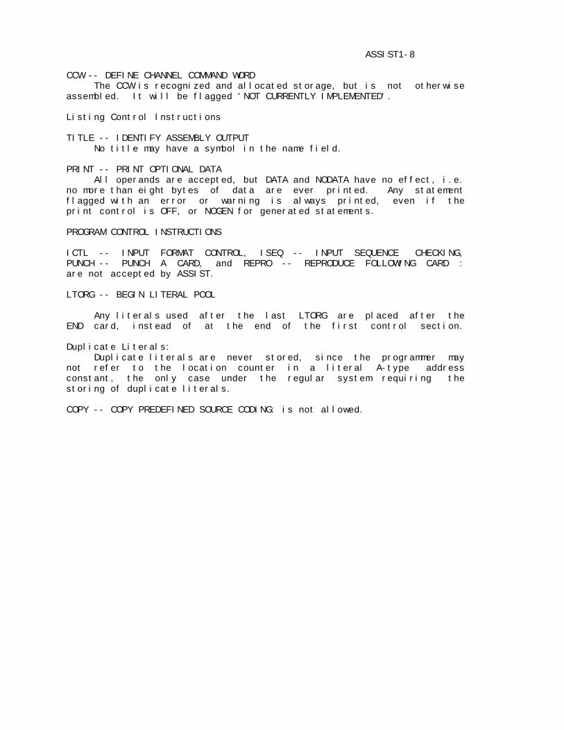
ASSIST1-8 CCW -- DEFINE CHANNEL COMMAND WORD The CCW is recognized and allocated storage, but is not otherwise assembled. It will be flagged 'NOT CURRENTLY IMPLEMENTED'. Listing Control Instructions TITLE -- IDENTIFY ASSEMBLY OUTPUT No title may have a symbol in the name field. PRINT -- PRINT OPTIONAL DATA All operands are accepted, but DATA and NODATA have no effect, i.e. no more than eight bytes of data are ever printed. Any statement flagged with an error or warning is always printed, even if the print control is OFF, or NOGEN for generated statements. PROGRAM CONTROL INSTRUCTIONS ICTL -- INPUT FORMAT CONTROL, ISEQ -- INPUT SEQUENCE CHECKING, PUNCH -- PUNCH A CARD, and REPRO -- REPRODUCE FOLLOWING CARD : are not accepted by ASSIST. LTORG -- BEGIN LITERAL POOL Any literals used after the last LTORG are placed after the END card, instead of at the end of the first control section. Duplicate Literals: Duplicate literals are never stored, since the programmer may not refer to the location counter in a literal A-type address constant, the only case under the regular system requiring the storing of duplicate literals. COPY -- COPY PREDEFINED SOURCE CODING: is not allowed.
ASSIST1-9 SECTION 6: INTRODUCTION TO THE MACRO LANGUAGE The macro language is a facility which may or may not be included in a particular version of ASSIST. Also, various levels of the ASSIST macro processor can be generated, so that the user should check to see which one(s) are available at his installation. The following facilities may be available: BASIC (F) MACRO FACILITY: allows programmer-written macros, compatible with Assembler(F), but without macro library or open code conditional assembly. EXTENDED (G&H) MACRO FACILITY: like BASIC above, but allows certain features not supported by Assembler F, but allowed by Assemblers G or H. MACRO LIBRARY: some versions of ASSIST permit system macros to be used in addition to programmer-written macros. This facility requires the use of a special comment card (*SYSLIB), as described later. OPEN CODE CONDITIONAL ASSEMBLY: system assemblers allow the user to use conditional assembly statements and SET variables outside macros, i.e., in the open code, or main body of the program. With certain restrictions as noted, this facility can be supplied if desired. Finally, in order to use macros at all, the user must supply the parameter MACRO= , as described in Part III. THE MACRO DEFINITION COPY statements are not allowed. THE MACRO LIBRARY Certain restrictions exist in ASSIST's processing of system macros. One or more *SYSLIB cards must follow any programmer-defined macro definitions. These cards indicate that library search is required, and must name any macros which are called from the open code later, but have not been previously mentioned in the programmer-written macros. The user should consult the appendix USE OF LIBRARY MACROS in this PART. SYSTEM AND PROGRAMMER MACRO DEFINITIONS Since ASSIST reads in system macros and edits them upon command of *SYSLIB cards immediately following programmer macros, they are treated exactly the same as programmer macros, except that they are not printed unless requested by the LIBMC option. Errors are attached to correct statements.

ASSIST1-10 SECTION 7: HOW TO PREPARE MACRO DEFINITIONS MACRO INSTRUCTION PROTOTYPE Two formats are allowed for statements, the normal one used by all other statements, and the alternate one allowed only for macro prototype and macro call statements. ASSIST does allow macro prototypes and macro calls to be continued on an indefinite number of cards. When there are no more than 2 continuation cards, ASSIST is completely compatible with other assemblers. If the total number of cards in a statement exceeds 3, the following restriction must be followed: every third card in the statement must use the alternate format, unless it is the last one. (This is done because ASSIST processes cards in groups of 3). The two prototypes below illustrate this restriction: PROTOTYPE ACCEPTED BY ASSEMBLERS F,G, H, VS, BUT NOT ASSIST: &LABEL LONGPROT &PARM1,&PARM2, PARMS,ALTERNATE FORMAT X &PARM3,&PARM4,&PARM5, PARMS,ALTERNATE FORMAT X &PARM6,&PARM7=XXXXXXXX,&PARM8=YYYYYYYY,&PARM9=ZZZZZZZZ,&X PARM9=A LAST LINE EQUIVALENT PROTOTYPE, ACCEPTED BY ASSIST: &LABEL LONGPROT &PARM1,&PARM2, PARMS,ALTERNATE FORMAT X &PARM3,&PARM4,&PARM5, PARMS,ALTERNATE FORMAT X &PARM6,&PARM7=XXXXXXXX,&PARM8=YYYYYYYY,&PARM9=ZZZZZZZZ, X &PARM9=A LAST LINE Given this restriction, it is best to place any positional parms early in the list if they may require long values needing continuation. MODEL STATEMENTS Variable symbols MAY be used to generate PRINT and END operations . If the open code feature is allowed, they may also be used to generate calls to macros at the outer level, but not inside macros. COPY STATEMENTS COPY statements are not allowed. SECTION 8: HOW TO WRITE MACRO-INSTRUCTIONS There are no changes from the IBM standard.

ASSIST1-11 SECTION 9: HOW TO WRITE CONDITIONAL ASSEMBLY INSTRUCTIONS All of the conditional assembly instructions may be used inside macros. They may only be used outside if the version of ASSIST being used supports it, and there are restrictions in that use in any case. ATTRIBUTES ASSIST is a two-pass assembler, performing macro-processing 'on the fly' during pass 1. As such, it is impossible for it to usually know the attributes of a symbol, so there are definite restrictions. In effect, the only attributes are those which can be found by looking just at a macro call statement by itself. The attributes allowed are: Attribute Notation Type T' only values N, O, and U possible Count K' Number N' Thus, Length (L'), Scaling (S'), and Integer (I') attributes are not supported. The only values for Type are N (Numeric), O (Omitted), and U (undefined), so that the value is U under ASSIST in many cases where it would be something else under IBM assemblers. AIF -- CONDITIONAL BRANCH IBM assemblers normally assign 4096 as the usual limit for number of AIF and AGO branches. See ACTR for the way ASSIST handles this. The sequence symbol named in the AIF may precede or follow the AIF statement inside macros. Outside macros, it may only follow the AIF, i.e., only forward branches are allowed. If a branch is taken to a previously-defined sequence symbol in open code, ASSIST produces an an error message and ignores the AIF/AGO. AGO -- UNCONDITIONAL BRANCH AGO follows the same restriction as AIF: backwards branches are allowed in macros, but not in open code. ACTR -- CONDITIONAL ASSEMBLY LOOP COUNTER ASSIST supports the standard ACTR. However, the default value of the ACTR counter is set differently, via the MACTR= option supplied by the user. This has a default value as given in PART III, which is normally smaller than the IBM value 4096. The MACTR= value is used for all macro definitions, unless explicitly overridden via ACTR statements. CONDITIONAL ASSEMBLY ELEMENTS There are no changes, except that attributes L', S', and I' are not supported.
ASSIST1-12 SECTION 10: EXTENDED FEATURES OF THE MACRO LANGUAGE MNOTE -- REQUEST FOR ERROR MESSAGE The MNOTE statements accepted by ASSIST follow the standard, but ASSIST effectively ignores the use of severity codes, except that MNOTE'S with numerical severity codes are printed as errors while ones with * are printed in another format. &SYSECT -- Current Control Section CSECT or DSECT statements processed in a macro definition do NOT affect the value for &SYSECT for any subsequent inner macros in that definition. MACRO DEFINITION COMPATIBILITY ASSIST does not accept AGOB or AIFB. APPENDIX K: USE OF LIBRARY MACROS This section describes the deck layout and use of *SYSLIB cards when the user desires to use macros from a system library. Brief notes are given regarding internal workings of macro processing, in order to help the requirements be more meaningful. ASSIST performs all macro-processing during the first pass of its total of two passes across the source program. Macro processing itself has two stages. During the EDIT stage, macro definitions are read, scanned, and printed, while tables are built in memory describing them. The EXPANSION stage is part of the normal first pass of a two-pass assembler, so that every time a macro call is encountered, the macro processor expands the call into 0 or more statements, which then act as though they had been read in the normal way. For best use of limited memory, ASSIST requires that ALL EDITING be done before ANY EXPANSION. During editing of programmer macros, a list is kept of opcodes not yet defined, and these are presumed to be system macros. Any system macros called by programmer macros are therefore known to ASSIST, and so it can fetch them from the library. However, if a system macro is only called at in the open code, there is no way for ASSIST to know that it will be needed later. Also, it is desirable that the user specify whether the macro library should be searched at all, in order to avoid searching the library for a mispelled opcode name automatically. Thus, a special comments card, *SYSLIB, is used to inform assist that it should actually perform library search. The format of the *SYSLIB card is either of the following: *SYSLIB name1,name2,...... comments *SYSLIB The first form gives a list of 1 or more macro names, seprated by commas, free format. The second form contains no operands at all.

ASSIST1-13 The second form may be used only when all library macros appear in the user's macro definitions. The *SYSLIB card should follow all programmer macros (if any), and must precede any of the statements of the open code, except for comment and listing control (PRINT, TITLE, EJECT, SPACE) statements. The user may supply 1 or more *SYSLIB cards, as long as these conditions are fulfilled, thus allowing some convenience. When finding any *SYSLIB card in a proper location, ASSIST does the following: 1. Scans the card, adding any name found there to the list of macro names. If the name is already in the list, it is totally ignored. 2. Scans the list of macro names. If a macro is not defined, it searches the macro library for it. If the macro cannot be obtained, it marks the macro 'searched for', and never looks for it again. 3. If the macro is found during 2, the print control is turned OFF, unless the user specified LIBMC, in which case the print control is unchanged. The macro is then read and edited, like a programmer macro. 4. During step 3, the macro being read may refer to other macros not yet defined, and these are added to the macro list also. The loop of steps 2,3,4 continues until all macros in the list have either been found or searched for. Thus, it is possible for a reference to one macro to cause a number of macros to be fetched from the library. At this point, print control is restored to its original value, and a list of undefined macros is produced. The following gives the overall layout of a program: ..... 0 or more programmer macro definitions, with print control statements interspersed if desired. ..... 1 or more *SYSLIB cards ..... 0 or more GBLx declarations (if open code cond. asm allowed) ..... 0 or more LCLx declarations " ..... ACTR " ..... open code (main body of program) The following shows appropriate *SYSLIB use, although the program itself should not be expected to make sense: MACRO PRGMAC1 &ARG CALL X MEND *SYSLIB SAVE WE WILL NEED SAVE MACRO *SYSLIB RETURN,EQUREGS OTHER MACROS NEEDED * CALL (USED IN PRGMAC1), IS NOT NEEDED (BUT COULD BE) ABOVE. USING *,15 SAVE (14,12) PRGMAC1 RETURN (14,12) EQUREGS
ASSIST1-14 HINTS ON OPTIMAL USE OF MACRO LIBRARY The user should be aware of the following when using the macro library facility: 1. The macro processor is mainly intended to process programmer- written macros. Among other things, all macro dictionaries and tables are kept in memory for the sake of speed. 2. Most IBM macros, and many XMACROS, call inner macros, which call other inner macros, which call others, etc, etc. Thus, calling one macro from the library may cause many others to be brought in. In particular, almost every IBM macro calls the macro IHBERMAC to issue MNOTE statements for any error messages. IHBERMAC contains over 400 statements, with many memory-consuming MNOTEs included. 3. If a macro is referenced, it is fetched from the library, whether it is actually ever called or not. For example, IHBERMAC is only called when there is an error, but is always fetched. 4. Given the combination of 1,2,3 above, it is easily possible to use macros like CALL, SAVE, RETURN, XSAVE, XRETURN, which do not in themselves seem large, but exceed memory quickly. (CALL, SAVE, RETURN all use IHBERMAC; XSAVE and XRETURN contain GETMAIN and FREEMAIN to support the REEN= option, and GETMAIN/FREEMAIN both call IHBERMAC). Another example is using ASSIST to check out a QSAM program: ask for OPEN, CLOSE, GET, PUT, and DCB: ASSIST processes these correctly, but 2700 statements are added to the program by the macros and all of the inner macros. A simple program can easily require 250K bytes of memory for assembly, given such macros. Given the above circumstances, care must be taken with the library facility in order to make efficeient use of it. Given such care, ASSIST is fast and small enough to check out fairly large programs in a 'reasonable' amount of memory and time. The following are useful tricks for saving time and space: 1. WRITE REDUCED VERSIONS OF COMMON MACROS, AND PLACE THEM IN A SPECIAL LIBRARY, TO BE ACCESSED FIRST BY ASSIST. For example, remove the REEN option from XSAVE/XRETURN, replace IHBERMAC calls by MNOTEs in CALL, SAVE, RETURN, etc. 2. USE LIBMC OPTION TO EXAMINE LIBRARY MACROS. WRITE DUMMY MACROS TO KEEP UNUSED ONES FROM BEING FETCHED. For example, if you know that a given macro will NOT actually be called, write a dummy, like: MACRO IHBERMAC &A,&B,&D,&E,&F,&H MNOTE 4,'PSEUDO IHBERMAC CALLED: &A,&B,&D,&E,&F,&H' MEND 3. IF NECESSARY, USE THE DISKU OPTION, IF AVAILABLE. The intermediate text saved between the two passes can be spilled to disk/drum, thus allowing more space for macro dictionaries, symbol table, etc.
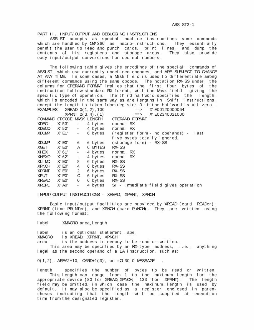
ASSIST2-1 PART II. INPUT/OUTPUT AND DEBUGGING INSTRUCTIONS ASSIST accepts as special machine instructions some commands which are handled by OS/360 as macro-instructions. They essentially permit the user to read and punch cards, print lines, and dump the contents of his registers and storage areas. They also provide easy input/output conversions for decimal numbers. The following table gives the encodings of the special commands of ASSIST, which use currently undefined opcodes, and ARE SUBJECT TO CHANGE AT ANY TIME. In some cases, a Mask field is used to differentiate among different commands using the same opcode. The notation RX-SS under the columns for OPERAND FORMAT implies that the first four bytes of the instruction follow standard RX format, with the Mask field giving the specific type of operation. The third halfword specifies the length, which is encoded in the same way as are lengths in Shift instructions, except the length is taken from register 0 if the halfword is all zero . EXAMPLES: XREAD 0(1,2),100 ==> X'E00120000064' XPRNT 2(3,4),(1) ==> X'E02340021000' COMMAND OPCODE MASK LENGTH OPERAND FORMAT XDECI X'53' - 4 bytes normal RX XDECO X'52' - 4 bytes normal RX XDUMP X'E1' - 6 bytes (register form - no operands) - last five bytes totally ignored. XDUMP X'E0' 6 6 bytes (storage form) - RX-SS XGET X'E0' A 6 BYTES RX-SS XHEXI X'61' - 4 bytes normal RX XHEXO X'62' - 4 bytes normal RX XLIMD X'E0' 8 6 bytes RX-SS XPNCH X'E0' 4 6 bytes RX-SS XPRNT X'E0' 2 6 bytes RX-SS XPUT X'E0' C 6 bytes RX-SS XREAD X'E0' 0 6 bytes RX-SS XREPL X'A0' - 4 bytes SI - immediate field gives operation INPUT/OUTPUT INSTRUCTIONS - XREAD, XPRNT, XPNCH Basic input/output facilities are provided by XREAD (card READer), XPRNT (line PRiNTer), and XPNCH (card PuNCH). They are written using the following format: label XMACRO area,length label is an optional statement label XMACRO is XREAD, XPRNT, XPNCH area is the address in memory to be read or written. This area may be specified by an RX-type address, i.e., anything legal as the second operand of a LA instruction, such as: 0(1,2), AREA2+10, CARD+1(3), or =CL30'0 MESSAGE' . length specifies the number of bytes to be read or written. This length can range from 1 to the maximum length for the appropriate device (80 for XREAD,XPNCH, 133 for XPRNT). The length field may be omitted, in which case the maximum length is used by default. It may also be specified as a register enclosed in paren- theses, indicating that the length will be supplied at execution time from the designated register.
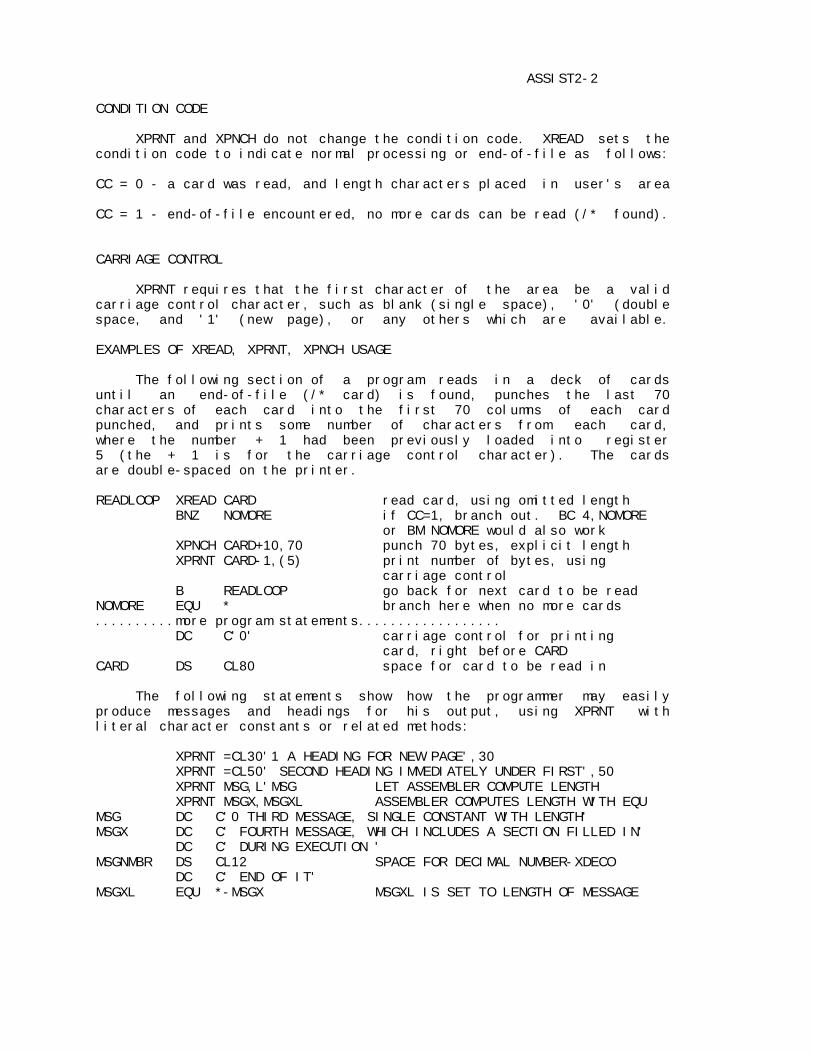
ASSIST2-2 CONDITION CODE XPRNT and XPNCH do not change the condition code. XREAD sets the condition code to indicate normal processing or end-of-file as follows: CC = 0 - a card was read, and length characters placed in user's area CC = 1 - end-of-file encountered, no more cards can be read (/* found). CARRIAGE CONTROL XPRNT requires that the first character of the area be a valid carriage control character, such as blank (single space), '0' (double space, and '1' (new page), or any others which are available. EXAMPLES OF XREAD, XPRNT, XPNCH USAGE The following section of a program reads in a deck of cards until an end-of-file (/* card) is found, punches the last 70 characters of each card into the first 70 columns of each card punched, and prints some number of characters from each card, where the number + 1 had been previously loaded into register 5 (the + 1 is for the carriage control character). The cards are double-spaced on the printer. READLOOP XREAD CARD read card, using omitted length BNZ NOMORE if CC=1, branch out. BC 4,NOMORE or BM NOMORE would also work XPNCH CARD+10,70 punch 70 bytes, explicit length XPRNT CARD-1,(5) print number of bytes, using carriage control B READLOOP go back for next card to be read NOMORE EQU * branch here when no more cards ..........more program statements.................. DC C'0' carriage control for printing card, right before CARD CARD DS CL80 space for card to be read in The following statements show how the programmer may easily produce messages and headings for his output, using XPRNT with literal character constants or related methods: XPRNT =CL30'1 A HEADING FOR NEW PAGE',30 XPRNT =CL50' SECOND HEADING IMMEDIATELY UNDER FIRST',50 XPRNT MSG,L'MSG LET ASSEMBLER COMPUTE LENGTH XPRNT MSGX,MSGXL ASSEMBLER COMPUTES LENGTH WITH EQU MSG DC C'0 THIRD MESSAGE, SINGLE CONSTANT WITH LENGTH' MSGX DC C' FOURTH MESSAGE, WHICH INCLUDES A SECTION FILLED IN' DC C' DURING EXECUTION ' MSGNMBR DS CL12 SPACE FOR DECIMAL NUMBER-XDECO DC C' END OF IT' MSGXL EQU *-MSGX MSGXL IS SET TO LENGTH OF MESSAGE
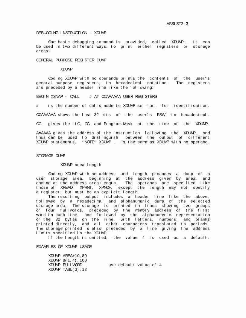
ASSIST2-3 DEBUGGING INSTRUCTION - XDUMP One basic debugging command is provided, called XDUMP. It can be used in two different ways, to print either registers or storage areas: GENERAL PURPOSE REGISTER DUMP XDUMP Coding XDUMP with no operands prints the contents of the user's general purpose registers, in hexadecimal notation. The registers are preceded by a header line like the following: BEGIN XSNAP - CALL # AT CCAAAAAA USER REGISTERS # is the number of calls made to XDUMP so far, for identification. CCAAAAAA shows the last 32 bits of the user's PSW, in hexadecimal. CC gives the ILC, CC, and Program Mask at the time of the XDUMP. AAAAAA gives the address of the instruction following the XDUMP, and thus can be used to distinguish between the output of different XDUMP statements. *NOTE* XDUMP , is the same as XDUMP with no operand. STORAGE DUMP XDUMP area,length Coding XDUMP with an address and length produces a dump of a user storage area, beginning at the address given by area, and ending at the address area+length. The operands are specified like those of XREAD, XPRNT, XPNCH, except the length may not specify a register, but must be an explicit length. The resulting output includes a header line like the above, followed by a hexadecimal and alphanumeric dump of the selected storage area. The storage is printed in lines showing two groups of four fullwords, preceded by the memory address of the first word in each line, and followed by the alphanumeric representation of the 32 bytes on the line, with letters, numbers, and blanks printed directly, and all other characters translated to periods. The storage printed is also preceded by a line giving the address limits specified in the XDUMP. If the length is omitted, the value 4 is used as a default. EXAMPLES OF XDUMP USAGE XDUMP AREA+10,80 XDUMP 8(1,4),100 XDUMP FULLWORD use default value of 4 XDUMP TABL(3),12
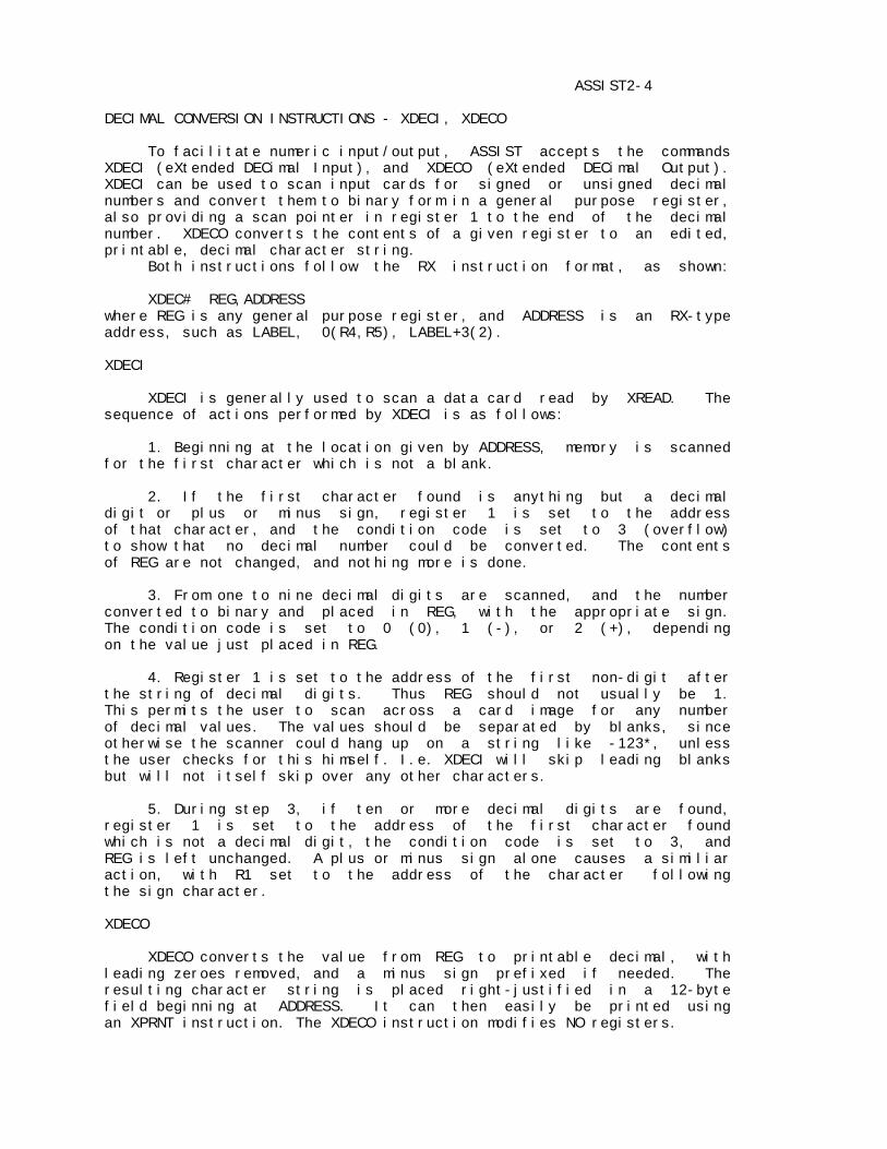
ASSIST2-4 DECIMAL CONVERSION INSTRUCTIONS - XDECI, XDECO To facilitate numeric input/output, ASSIST accepts the commands XDECI (eXtended DECimal Input), and XDECO (eXtended DECimal Output). XDECI can be used to scan input cards for signed or unsigned decimal numbers and convert them to binary form in a general purpose register, also providing a scan pointer in register 1 to the end of the decimal number. XDECO converts the contents of a given register to an edited, printable, decimal character string. Both instructions follow the RX instruction format, as shown: XDEC# REG,ADDRESS where REG is any general purpose register, and ADDRESS is an RX-type address, such as LABEL, 0(R4,R5), LABEL+3(2). XDECI XDECI is generally used to scan a data card read by XREAD. The sequence of actions performed by XDECI is as follows: 1. Beginning at the location given by ADDRESS, memory is scanned for the first character which is not a blank. 2. If the first character found is anything but a decimal digit or plus or minus sign, register 1 is set to the address of that character, and the condition code is set to 3 (overflow) to show that no decimal number could be converted. The contents of REG are not changed, and nothing more is done. 3. From one to nine decimal digits are scanned, and the number converted to binary and placed in REG, with the appropriate sign. The condition code is set to 0 (0), 1 (-), or 2 (+), depending on the value just placed in REG. 4. Register 1 is set to the address of the first non-digit after the string of decimal digits. Thus REG should not usually be 1. This permits the user to scan across a card image for any number of decimal values. The values should be separated by blanks, since otherwise the scanner could hang up on a string like -123*, unless the user checks for this himself. I.e. XDECI will skip leading blanks but will not itself skip over any other characters. 5. During step 3, if ten or more decimal digits are found, register 1 is set to the address of the first character found which is not a decimal digit, the condition code is set to 3, and REG is left unchanged. A plus or minus sign alone causes a similiar action, with R1 set to the address of the character following the sign character. XDECO XDECO converts the value from REG to printable decimal, with leading zeroes removed, and a minus sign prefixed if needed. The resulting character string is placed right-justified in a 12-byte field beginning at ADDRESS. It can then easily be printed using an XPRNT instruction. The XDECO instruction modifies NO registers.
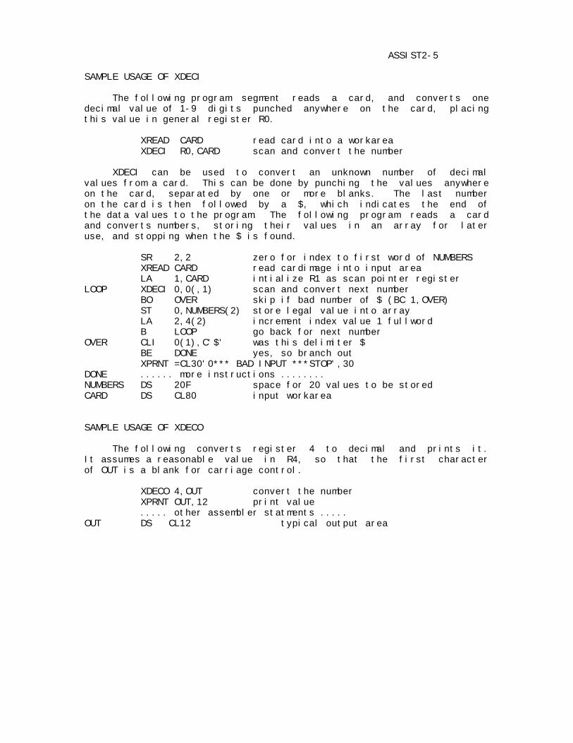
ASSIST2-5 SAMPLE USAGE OF XDECI The following program segment reads a card, and converts one decimal value of 1-9 digits punched anywhere on the card, placing this value in general register R0. XREAD CARD read card into a workarea XDECI R0,CARD scan and convert the number XDECI can be used to convert an unknown number of decimal values from a card. This can be done by punching the values anywhere on the card, separated by one or more blanks. The last number on the card is then followed by a $, which indicates the end of the data values to the program. The following program reads a card and converts numbers, storing their values in an array for later use, and stopping when the $ is found. SR 2,2 zero for index to first word of NUMBERS XREAD CARD read cardimage into input area LA 1,CARD intialize R1 as scan pointer register LOOP XDECI 0,0(,1) scan and convert next number BO OVER skip if bad number of $ (BC 1,OVER) ST 0,NUMBERS(2) store legal value into array LA 2,4(2) increment index value 1 fullword B LOOP go back for next number OVER CLI 0(1),C'$' was this delimiter $ BE DONE yes, so branch out XPRNT =CL30'0*** BAD INPUT ***STOP',30 DONE ...... more instructions ........ NUMBERS DS 20F space for 20 values to be stored CARD DS CL80 input workarea SAMPLE USAGE OF XDECO The following converts register 4 to decimal and prints it. It assumes a reasonable value in R4, so that the first character of OUT is a blank for carriage control. XDECO 4,OUT convert the number XPRNT OUT,12 print value ..... other assembler statments ..... OUT DS CL12 typical output area
ASSIST2-6 HEXADECIMAL CONVERSION INSTRUCTIONS-XHEXI, XHEXO (NOTE: Some versions of ASSIST may not provide these instructions) XHEXI and XHEXO provide easy conversion of hexadecimal numbers for input and output. The value of a hexadecimal number can be read from a card using XREAD, converted from character mode to a hexadecimal number, and the converted number is placed in the specified general purpose register with XHEXI. XHEXO provides an easy way to convert internal hexadecimal to an output form that can be printed using XPRNT. XHEXI also places the address of the first non-hexadecimal number in register one, but if more than eight digits are scanned, the address of the ninth is placed in register 1. XHEXI XHEXI REGISTER,ADDRESS XHEXI, in the general form shown above where REGISTER is any general purpose register and ADDRESS is anything legal in an RX instruction, is used to do the following: 1. Beginning at the location ADDRESS, memory is scanned until the first non-blank character is found. 2. If the first character found is anything but a legal hexa- decimal character(0-9,A-F), the condition code is set to overflow and this address is placed in register 1. If the REGISTER is anything but register 1, its contents remain unchanged. 3. One to eight hexadecimal characters are scanned, the number converted to hexadecimal, and the result is placed in REGISTER. The value placed in the register is internal hexadecimal with leading zeros included and the number is right justified. 4. Register one is set to the address of the first non-hexadecimal character. With this in mind, the user should not code register one as REGISTER. This allows you to scan across the card for any number of character strings. The strings should be separated by blanks. The end of the string could be flagged with any non-hexadecimal character and a test could be made after a Branch Overflow (see sample program). 5. If more than eight hex digits are found, register one is set to the address of the ninth. This allows the user to scan across long strings of numbers. XHEXO XHEXO REGISTER,ADDRESS XHEXO in the general form shown above converts the value in REGISTER and places it in a right-justified 8-byte field beginning at ADDRESS. It can be easily printed using an XPRNT instruction. The XHEXO instruction modifies NO registers.

ASSIST2-7 SAMPLE PROGRAM USING XHEXI AND XHEXO This program reads a data card with an unknown number of hexa- decimal numbers on it. The end of the data is denoted by a '%' punched after the last number. The numbers are stored after being converted using XHEXI, and then converted for output using XHEXO. LA 3,STORAGE WHERE NUMBERS STORED XREAD CARD,80 READ IN CARD XPRNT CARD,80 ECHO PRINT LA 1,CARD ADDRESS OF CARD FOR SCANNING LOOP XHEXI 2,0(1) CONVERT NUMBER PUT IN 2 BO ILLEGAL CHECK FOR END XHEXO 2,AREA PUT NUMBER IN OUTPUT AREA XPRNT REP,28 PRINT CARD AND MESSAGE ST 2,0(3) STORE NUMBER LA 3,4(3) INCREASE INDEX B LOOP GET NEXT NUMBER ILLEGAL CLI 0(1),C'%' SEE IF END OF STRING BE DONE YES DONE XPRNT =CL50' ILLEGAL CHARACTER STOP',50 DONE ....MORE INSTRUCTIONS..... CARD DC 81C' ' STORAGE FOR CARD STORAGE DS 20F STORAGE FOR NUMBERS REP DC C' THE NUMBER IN R2 IS' AREA DC CL8' ' STORAGE FOR OUTPUT NUMBER
ASSIST2-8 LIMIT DUMP INSTRUCTION - XLIMD In order to conserve output records when necessary (for instance, when ASSIST is being used from a remote terminal of any sort), the XLIMD instruction is provided to enable the user to limit the size of his completion dump and choose the area to be printed. In general, it is used to eliminate the user's program code, leaving only his data areas in the completion dump. The instruction is coded as follows: XLIMD area,length area is the beginning address where the completion dump should start. The area address is specified by an RX-type address, and must be within the user program area. length is the length in bytes of the area the user wishes to be printed if a completion dump occurs. Note that the XLIMD instruction format is exactly the same as that for the instructions XREAD, XPRNT, XPNCH. Thus the length may be given as a register number, enclosed in parentheses, or may be omitted, in which case a length of 1 is assumed. If the combined area address plus the length yields an address greater than the highest user address, or if the length is 1, the highest user address is used as an upper limit instead. Thus, storage will be printed to the end of the user program. The suggested method of using XLIMD is to place all variables at the end of the program, then execute an XLIMD with an area address specifying the first variable desired, and omitting the length. This will cause the storage to be printed starting at the specfied address and going to the end of the program. SAMPLE USAGE OF XLIMD The following program gives a typical way of using XLIMD. DUMPTEST CSECT USING *,15 XLIMD VARIABL1 set dump limit right away .......... large number of machine instructions .......... VARIABL1 DS D first variable area .......... variable areas likely to be required for debugging .......... END XLIMD may be executed any number of times during a program, but it is suggested that it be called early in any large program, if there is any possiblity that record limits could be exceeded.
ASSIST2-9 OPTIONAL INPUT/OUTPUT INSTRUCTIONS - XGET AND XPUT These instructions are similar to XREAD/XPRNT/XPNCH, but are more general, allowing the user to specify any filename to be read or written. WARNING: not all versions of ASSIST support these instructions. Also, a particular version may only support a specific set of file names, which can differ from installation to installation. It is advisable to check on local procedures. The instructions are coded as follows: label xmacro area,length label is an optional statement label xmacro is either XGET or XPUT area is the address in memory to be read or written. This area may be specified by an RX-type address, i.e., anything legal as the second operand of a LA instruction, such as: 0(1,2),AREA2+10,card+1(3), or =CL30'0 MESSAGE' . length specifies the number of bytes to be read or written. This length can range from 1 to the maximum length for the appropriate device (80 for cards, 133 for printer, etc.). The length field must not be omitted. it may also be specified as a register enclosed in parentheses, indicating that the length will be supplied at execution time from the designated register. If during execution, the length has a value of zero, the file will be closed. NOTE: During execution, register 1 must point to an eight byte character string which is the name of the file to be manipulated. CONDITION CODE XGET and XPUT both change the condition code as follows: CC=0 - normal input/output occurred CC=1 - XGET ONLY - end of file occurred CC=2 shows an error (like invalid data address) which causes individual operation to be ignored. CC=3 shows that the file could not be opened (because it is wrong direction,or DD card missing, or not enough room in tables, etc.). CARRIAGE CONTROL XPUT only requires the first character of the area to be a valid carriage control character, if the output device is the printer. CLOSING OF FILE Performing an XGET or XPUT with a length of zero supplied in any GP register causes the designated file to be closed, so that it may then be reread; I.e. LA 1,=CL8'ddname' SR 0,0 XGET area,(0) does close.
ASSIST2-10 EXAMPLE OF XGET AND XPUT USAGE The following program will read and write a few files in parallel. TEST1 CSECT BALR 12,0 USING *,12 SR 0,0 * * THIS PROGRAM WILL PROCESS A FEW FILES IN PARALLEL: * LOOP LA 1,=CL8'CARD' point to an input file XGET AREA,80 do the input BNE DONE branch on endfile, * file automatically closed XREAD AREA2,80 do normal input LA 1,=CL8'PAPER' point to a printer file XPUT AREA-1,81 do output, note carriage control LA 1,=CL8'PAPER2' point to other printer file XPUT AREA2-1,81 do output on other file B LOOP try again DONE BR 14 RETURN, IMPLICITLY CLOSE OTHER FILES DC CL1' ' AREA DS CL80 DC CL1' ' AREA2 DS CL80 END The extra JCL for the above is as follows: //DATA.PAPER DD SYSOUT=A,DCB=(RECFM=FA,LRECL=133,BLKSIZE=133) //DATA.PAPER2 DD SYSOUT=A,DCB=(RECFM=FA,LRECL=133,BLKSIZE=133) //DATA.CARD DD * THIS STUFF IS READ AT THE SAME TIME AS ANOTHER FILE IS READ ****** THE LAST CARD ******* //DATA.INPUT DD * THIS IS THE NORMAL INPUT FILE AND IS READ AT THE SAME TIME AS ANOTHER FILE IS READ ********* THE LAST CARD ********* NOTE: a common usage for XGET might be to access files of test data.
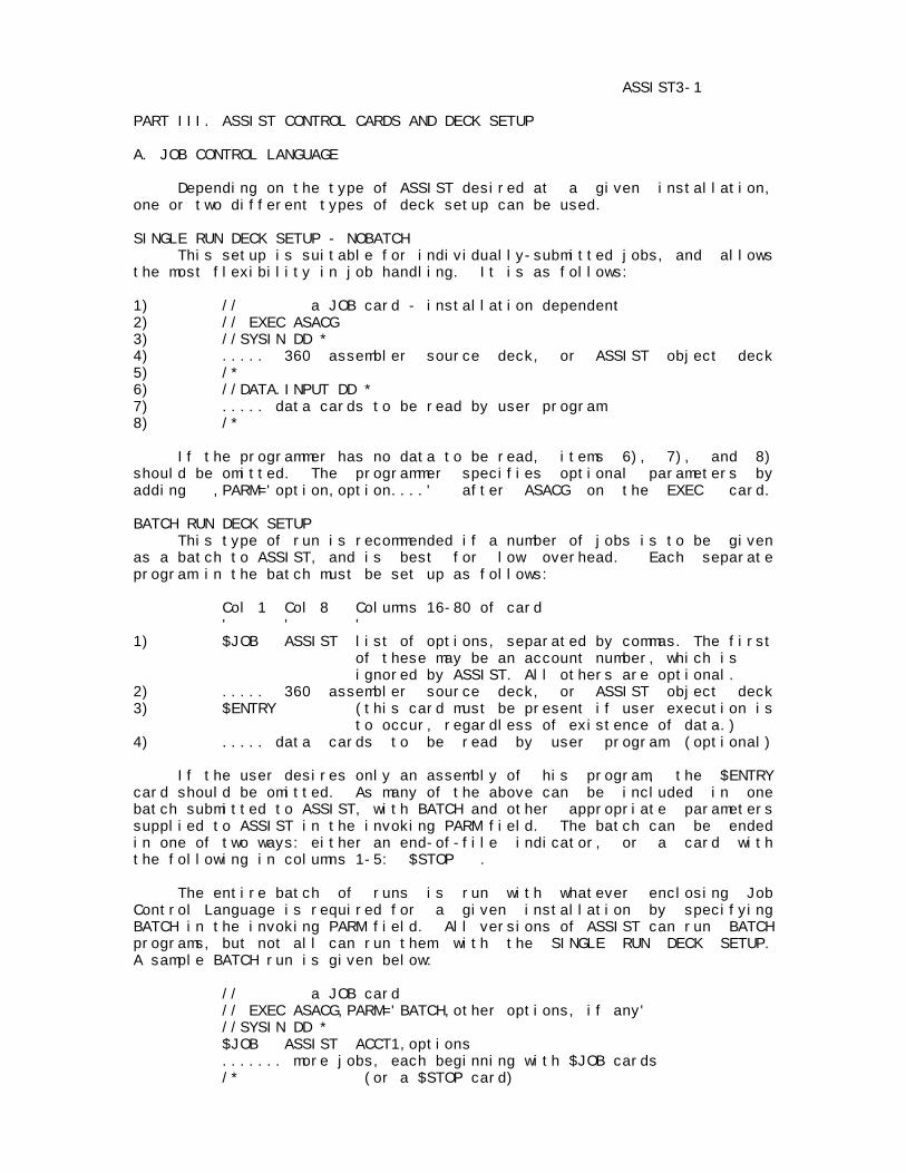
ASSIST3-1 PART III. ASSIST CONTROL CARDS AND DECK SETUP A. JOB CONTROL LANGUAGE Depending on the type of ASSIST desired at a given installation, one or two different types of deck setup can be used. SINGLE RUN DECK SETUP - NOBATCH This setup is suitable for individually-submitted jobs, and allows the most flexibility in job handling. It is as follows: 1) // a JOB card - installation dependent 2) // EXEC ASACG 3) //SYSIN DD * 4) ..... 360 assembler source deck, or ASSIST object deck 5) /* 6) //DATA.INPUT DD * 7) ..... data cards to be read by user program 8) /* If the programmer has no data to be read, items 6), 7), and 8) should be omitted. The programmer specifies optional parameters by adding ,PARM='option,option....' after ASACG on the EXEC card. BATCH RUN DECK SETUP This type of run is recommended if a number of jobs is to be given as a batch to ASSIST, and is best for low overhead. Each separate program in the batch must be set up as follows: Col 1 Col 8 Columns 16-80 of card ' ' ' 1) $JOB ASSIST list of options, separated by commas. The first of these may be an account number, which is ignored by ASSIST. All others are optional. 2) ..... 360 assembler source deck, or ASSIST object deck 3) $ENTRY (this card must be present if user execution is to occur, regardless of existence of data.) 4) ..... data cards to be read by user program (optional) If the user desires only an assembly of his program, the $ENTRY card should be omitted. As many of the above can be included in one batch submitted to ASSIST, with BATCH and other appropriate parameters supplied to ASSIST in the invoking PARM field. The batch can be ended in one of two ways: either an end-of-file indicator, or a card with the following in columns 1-5: $STOP . The entire batch of runs is run with whatever enclosing Job Control Language is required for a given installation by specifying BATCH in the invoking PARM field. All versions of ASSIST can run BATCH programs, but not all can run them with the SINGLE RUN DECK SETUP. A sample BATCH run is given below: // a JOB card // EXEC ASACG,PARM='BATCH,other options, if any' //SYSIN DD * $JOB ASSIST ACCT1,options ....... more jobs, each beginning with $JOB cards /* (or a $STOP card)

ASSIST3-2 B. OPTIONAL PARAMETERS FOR ASSIST ASSIST provides a large number of options to control the actions it performs. These options are of two types: the first kind show yes/no values and are coded as a specific name, with or without a preceding NO. Every option has a default value, and some of the numerical ones have upper limits which can never be exceeded. Each parameter can possibly be given values from at most four different sources, which are as follows: 1. LIMIT/DEFAULT - absolute upper limits on some numerical options, and default values for some others. (defined inside ASSIST) 2. INVOKING PARM - values for any of the options. (EXEC CARD PARM field, or PARM supplied by another program calling ASSIST) **NOTE** this is not available under DOS/360. 3. $JOB CARD PARM - values for some of the options, if desired, only possible if LIMIT/DEFAULT or INVOKING PARM specified BATCH. 4. DEFAULT - default values for the numerical parameters having upper limits, only used if values not specified in 2. or 3. (defined inside ASSIST) For any assembly-execution-dump cycle of ASSIST (i.e., one program) the above sources of information are processed in the order given above, subject to the following rules: 1. Some options can be supplied values only from certain sources. 2. Certain numerical parameters can never be increased beyond any previous setting from any source. This particularly applies to time, records, and pages limits. 3. In most cases, if the same option is coded several times in the same information source, the last value is used, subject to rule 2. It is possible that some values cannot be reset once set anywhere. 4. DEFAULT values are used only if they are not coded in either the INVOKING PARM or $JOB cards, i.e., they override only LIMIT/DEFAULT values. This construct allows for both limit and default values for the numerical options. SAMPLE USAGE OF OPTIONAL PARAMETERS 1) // EXEC ASACG,PARM='T=3.5,R=200,NERR=10,RELOC,CMPRS' 2) // EXEC ASACG,PARM='BATCH,CPAGE,T=5,TX=2,P=20,PX=5,RX=315,SSD' //SYSIN DD * $JOB ASSIST ACCT#,PD=1,TD=0.05,CMPRS,SS,SSX (this job crams output onto fewest possible pages) ............. $JOB ASSIST ACCT#,PD=0,TD=0,RD=0 (this is a debugged program-saves no pages,time, or records for the dump-gets maximum output). ............. $JOB ASSIST ACCT#,OBJIN ............. (object deck) The above examples show a typical single job run and a typical batch of jobs.
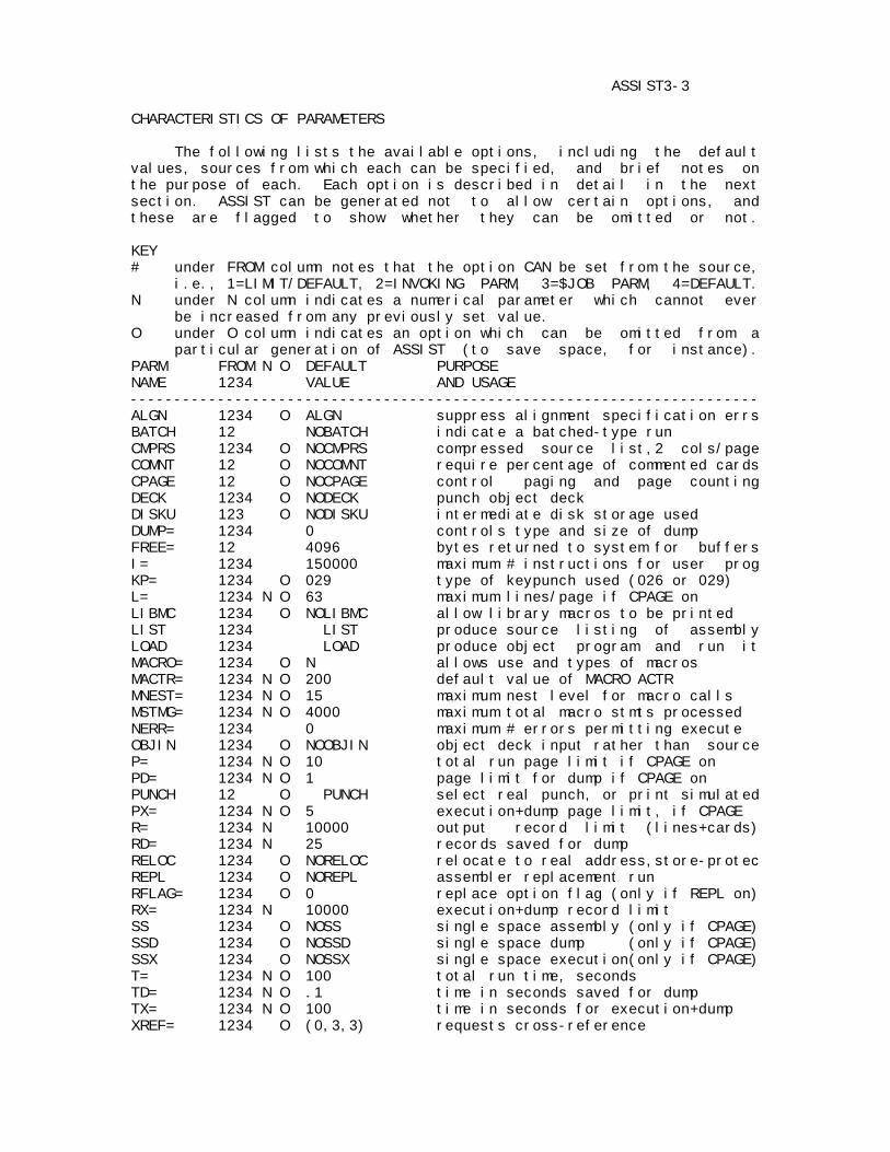
ASSIST3-3 CHARACTERISTICS OF PARAMETERS The following lists the available options, including the default values, sources from which each can be specified, and brief notes on the purpose of each. Each option is described in detail in the next section. ASSIST can be generated not to allow certain options, and these are flagged to show whether they can be omitted or not. KEY # under FROM column notes that the option CAN be set from the source, i.e., 1=LIMIT/DEFAULT, 2=INVOKING PARM, 3=$JOB PARM, 4=DEFAULT. N under N column indicates a numerical parameter which cannot ever be increased from any previously set value. O under O column indicates an option which can be omitted from a particular generation of ASSIST (to save space, for instance). PARM FROM N O DEFAULT PURPOSE NAME 1234 VALUE AND USAGE ------------------------------------------------------------------------ ALGN 1234 O ALGN suppress alignment specification errs BATCH 12 NOBATCH indicate a batched-type run CMPRS 1234 O NOCMPRS compressed source list,2 cols/page COMNT 12 O NOCOMNT require percentage of commented cards CPAGE 12 O NOCPAGE control paging and page counting DECK 1234 O NODECK punch object deck DISKU 123 O NODISKU intermediate disk storage used DUMP= 1234 0 controls type and size of dump FREE= 12 4096 bytes returned to system for buffers I= 1234 150000 maximum # instructions for user prog KP= 1234 O 029 type of keypunch used (026 or 029) L= 1234 N O 63 maximum lines/page if CPAGE on LIBMC 1234 O NOLIBMC allow library macros to be printed LIST 1234 LIST produce source listing of assembly LOAD 1234 LOAD produce object program and run it MACRO= 1234 O N allows use and types of macros MACTR= 1234 N O 200 default value of MACRO ACTR MNEST= 1234 N O 15 maximum nest level for macro calls MSTMG= 1234 N O 4000 maximum total macro stmts processed NERR= 1234 0 maximum # errors permitting execute OBJIN 1234 O NOOBJIN object deck input rather than source P= 1234 N O 10 total run page limit if CPAGE on PD= 1234 N O 1 page limit for dump if CPAGE on PUNCH 12 O PUNCH select real punch, or print simulated PX= 1234 N O 5 execution+dump page limit, if CPAGE R= 1234 N 10000 output record limit (lines+cards) RD= 1234 N 25 records saved for dump RELOC 1234 O NORELOC relocate to real address,store-protec REPL 1234 O NOREPL assembler replacement run RFLAG= 1234 O 0 replace option flag (only if REPL on) RX= 1234 N 10000 execution+dump record limit SS 1234 O NOSS single space assembly (only if CPAGE) SSD 1234 O NOSSD single space dump (only if CPAGE) SSX 1234 O NOSSX single space execution(only if CPAGE) T= 1234 N O 100 total run time, seconds TD= 1234 N O .1 time in seconds saved for dump TX= 1234 N O 100 time in seconds for execution+dump XREF= 1234 O (0,3,3) requests cross-reference
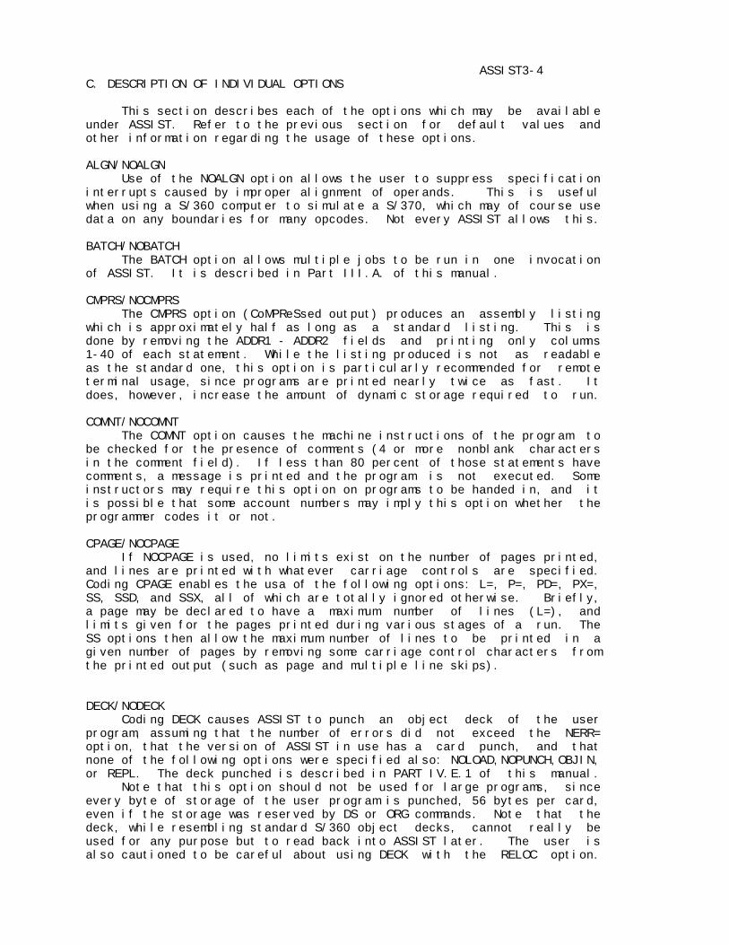
ASSIST3-4 C. DESCRIPTION OF INDIVIDUAL OPTIONS This section describes each of the options which may be available under ASSIST. Refer to the previous section for default values and other information regarding the usage of these options. ALGN/NOALGN Use of the NOALGN option allows the user to suppress specification interrupts caused by improper alignment of operands. This is useful when using a S/360 computer to simulate a S/370, which may of course use data on any boundaries for many opcodes. Not every ASSIST allows this. BATCH/NOBATCH The BATCH option allows multiple jobs to be run in one invocation of ASSIST. It is described in Part III.A. of this manual. CMPRS/NOCMPRS The CMPRS option (CoMPReSsed output) produces an assembly listing which is approximately half as long as a standard listing. This is done by removing the ADDR1 - ADDR2 fields and printing only columns 1-40 of each statement. While the listing produced is not as readable as the standard one, this option is particularly recommended for remote terminal usage, since programs are printed nearly twice as fast. It does, however, increase the amount of dynamic storage required to run. COMNT/NOCOMNT The COMNT option causes the machine instructions of the program to be checked for the presence of comments (4 or more nonblank characters in the comment field). If less than 80 percent of those statements have comments, a message is printed and the program is not executed. Some instructors may require this option on programs to be handed in, and it is possible that some account numbers may imply this option whether the programmer codes it or not. CPAGE/NOCPAGE If NOCPAGE is used, no limits exist on the number of pages printed, and lines are printed with whatever carriage controls are specified. Coding CPAGE enables the usa of the following options: L=, P=, PD=, PX=, SS, SSD, and SSX, all of which are totally ignored otherwise. Briefly, a page may be declared to have a maximum number of lines (L=), and limits given for the pages printed during various stages of a run. The SS options then allow the maximum number of lines to be printed in a given number of pages by removing some carriage control characters from the printed output (such as page and multiple line skips). DECK/NODECK Coding DECK causes ASSIST to punch an object deck of the user program, assuming that the number of errors did not exceed the NERR= option, that the version of ASSIST in use has a card punch, and that none of the following options were specified also: NOLOAD,NOPUNCH,OBJIN, or REPL. The deck punched is described in PART IV.E.1 of this manual. Note that this option should not be used for large programs, since every byte of storage of the user program is punched, 56 bytes per card, even if the storage was reserved by DS or ORG commands. Note that the deck, while resembling standard S/360 object decks, cannot really be used for any purpose but to read back into ASSIST later. The user is also cautioned to be careful about using DECK with the RELOC option.
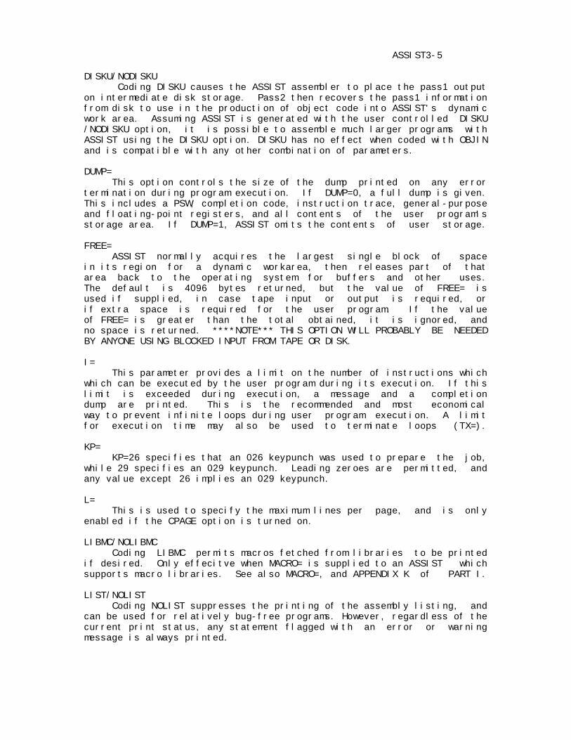
ASSIST3-5 DISKU/NODISKU Coding DISKU causes the ASSIST assembler to place the pass1 output on intermediate disk storage. Pass2 then recovers the pass1 information from disk to use in the production of object code into ASSIST's dynamic work area. Assuming ASSIST is generated with the user controlled DISKU /NODISKU option, it is possible to assemble much larger programs with ASSIST using the DISKU option. DISKU has no effect when coded with OBJIN and is compatible with any other combination of parameters. DUMP= This option controls the size of the dump printed on any error termination during program execution. If DUMP=0, a full dump is given. This includes a PSW, completion code, instruction trace, general-purpose and floating-point registers, and all contents of the user program's storage area. If DUMP=1, ASSIST omits the contents of user storage. FREE= ASSIST normally acquires the largest single block of space in its region for a dynamic workarea, then releases part of that area back to the operating system for buffers and other uses. The default is 4096 bytes returned, but the value of FREE= is used if supplied, in case tape input or output is required, or if extra space is required for the user program. If the value of FREE= is greater than the total obtained, it is ignored, and no space is returned. ****NOTE*** THIS OPTION WILL PROBABLY BE NEEDED BY ANYONE USING BLOCKED INPUT FROM TAPE OR DISK. I= This parameter provides a limit on the number of instructions which which can be executed by the user program during its execution. If this limit is exceeded during execution, a message and a completion dump are printed. This is the recommended and most economical way to prevent infinite loops during user program execution. A limit for execution time may also be used to terminate loops (TX=). KP= KP=26 specifies that an 026 keypunch was used to prepare the job, while 29 specifies an 029 keypunch. Leading zeroes are permitted, and any value except 26 implies an 029 keypunch. L= This is used to specify the maximum lines per page, and is only enabled if the CPAGE option is turned on. LIBMC/NOLIBMC Coding LIBMC permits macros fetched from libraries to be printed if desired. Only effecitve when MACRO= is supplied to an ASSIST which supports macro libraries. See also MACRO=, and APPENDIX K of PART I. LIST/NOLIST Coding NOLIST suppresses the printing of the assembly listing, and can be used for relatively bug-free programs. However, regardless of the current print status, any statement flagged with an error or warning message is always printed.
ASSIST3-6 LOAD/NOLOAD Under most circumstances, a programmer usually wants to execute his assembler program. If he just wants to check it for errors, but not execute it, the NOLOAD option can be coded. This will result in slightly faster assembly times. In addition, it will require less space in memory, and it may be possible to assemble a program under NOLOAD that cannot be assembled with the LOAD option. MACRO= This option notes whether macro processing is to be done, and if so, what language facilities are to be allowed. The values allowed are: MACRO=N NO macro processing: used if error in option MACRO=F F-level Assembler compatibility (basic facility) MACRO=G G-level Assembler features added, if available MACRO=H H-level Assembler features added, if available If macros or conditional assembly are to be used, the user MUST specify something other than MACRO=N. See also APPENDIX K of PART I. MACTR= This provides a default value for the starting ACTR counters in all macros used. It can be overridden by explicit ACTR statements. MNEST= This gives a limit on the maximum level of nested macro calls, thus allowing prevention of unwanted recursion in macros. MSTMG= This provides a global limit on the total statements processed in all macro expansions. It is like ACTR, but counts all statements in all macros, rather than being local to a macro. It can be used to prevent macro looping which causes storage to be exceeded. NERR= This option is used to allow a program to execute even though there are errors in it. If omitted, the value is assumed to be zero, i.e., the program is not executed if there are any errors at all in it. If NERR=10 is used, the program runs if it has 10 errors, but does not run if there are 11. Note that warning messages are not included in this count, only actual error messages. OBJIN/NOOBJIN Coding OBJIN informs ASSIST that an object deck is being supplied to it in place of the usual assembler source deck. This is allowed in every case, unless REPL is coded, in which case OBJIN is ignored. The format required of the object deck is given in PART IV.E.1. The ASSIST loader reads the object deck until an end-of-file or ASSIST control card is found, producing an object program in memory which is then treated exactly as though the source program had been just assembled there. The loader also issues various messages of the form AL###, which are explained in PART IV.E.2. The user should read all of PART IV.E. before using the OBJIN option, since there are a number of restrictions which must be noted before using object decks as input to ASSIST. In general, a single ASSIST-produced deck should almost always be workable, a single deck produced by the standard system assembler, or multiple decks of any sort may be usable if they were created following certain conventions. Decks requiring symbolic linkage among control sections will definitely NOT run correctly.

ASSIST3-7 P= This gives the maximum number of pages (with L= lines per page) which are permitted for a complete job (or from one $JOB card to the next, if BATCH is used). It is only meaningful if CPAGE is on. The entire process of page counting (which also involves values of PD= and PX= ) is summarized as follows: 1. As described in PART III.B, the value of P= is calculated before ASSIST prints anything for the job. ASSIST prints the beginning of the header line, followed by the PARM field, or the $JOB card, and then assembly begins. If the p= value is exceeded during assembly, the job is halted at that point. 2. If the user program assembles successfully and is to be executed, a page limit is calculated for execution plus dump. The total for these two phases is set to the minimum of the PX= option and the number of pages remaining from before. 3. A temporary limit for user program execution alone is calculated by subtracting the value of the PD= option, thus reserving that number of pages for a dump. User program execution occurs, and may be terminated if the temporary page limit is exceeded. 4. After execution, the PD= value is added to the current pages remaining counter, and the dump begun. The dump continues until it is completed or it runs out of pages. Note A. At steps 3 and 4 the lines remaining count is just carried forward, so that the user gets the benefit of any partial pages. Note B. For REPL runs (assembler replacement), step three is performed twice, once for the replacement program, and once for the program it assembles (if execution is desired for it). Since a dump of the replacement program does not occur during the user dump phase, it is recommended that no pages be saved for it (i.e., PD=0). Note C. Any process which can be halted by exceeding page count can also be halted by exceeding record limits (see R=), or time limits (see T=), and for user program execution, exceeding instruction count limit (see I=). PD= This option specifies the number of pages which should be reserved for the user completion dump phase. It is effective only if CPAGE is on, and is used in conjunction with P= and PX= ( see explanation under P=). Typical values are as follows: PD=0 saves no pages for dump. Good for debugged programs. PD=1 even if the program loops printing, this allows enough information to determine what the program was doing. If SSD is coded, about 1K of storage can also be seen. Note that the PD= value does not restrict a dump to that size, so that the user also gets up to the PX= value for execution plus dump together, even if the entire amount is used to provide the dump. PUNCH/NOPUNCH Use of the NOPUNCH parameter causes the system to print any output from XPNCH instructions, rather than punching them. Each cardimage is preceded with the characters ' CARD-->' to distinguish it from other printed output. This option is useful for testing punching programs. Versions of ASSIST with no punch treat all attempted punching this way.
ASSIST3-8 PX= This gives the maximum number of pages for both user program execution and completion dump phases together. It is effective only if CPAGE is on. See description under P=. R= This value specifies the maximum number of output records (lines printed + cards punched) allowed for the entire run. Record counting is always performed, and the entire process resembles that of page counting (see P=), and occurs in parallel with any page counting. The parameters R=, and RX= are used just as are P=, PX=, and PD=, with records substituted for pages. One possible difference is in ASSIST systems with special record control type 2 (see header description - PART IV.B.1.a.). In this case, the initial record remaining count is also determined by the number of records actually left (if this value can be obtained from the operating system). This value is used rather than the default value if the user did not specify R= on the EXEC card or $JOB card. As in Note B. under P=, use RD=0 for replacement runs. RD= RD= the number of output records reserved for a user completion dump It is used in conjunction with R= and RX= in the same way that PD= is used with P= and PX=. RD=0 is appropriate for well-debugged programs, and RD=25 is probably the most reasonable value for most runs, as it saves enough for a partial dump under all conditions. RELOC/NORELOC Under NORELOC a user program is assembled with a location counter beginning either at 0 or the value on a start card, and the program is executed as though it were actually loaded at whatever addresses are given on the assembly listing. Maximum debugging checking is provided by this mode, as the user may not branch, store, or fetch outside the area of his program. RELOC in effect inserts a start card at the beginning of the source program which specifies the actual location in memory at which the user program will be assembled. When the program is executed, fetch protection is eliminated, which the execution-time relocation value of zero, allows the user program to examine any areas of storage in the computer (for example, to trace system control blocks). RELOC mode is implied if REPL is coded. REPL/NOREPL REPL notes that the user supplies two source programs, of which the first is a replacement for one of the modules of the ASSIST assembler, and the second is a test program, to be assembled using the replacement program. This optional feature is described in detail in the ASSIST ASSEMBLER REPLACEMENT USER'S GUIDE. RFLAG This option specifies an initial value for the replace control flag, it is meaningful only if REPL is coded, and is described in the ASSIST ASSEMBLER REPLACEMENT USER'S GUIDE.
ASSIST3-9 RX= This gives the total number of output records for user program execution and dump together (see R=). It corresponds to PX= for page control, and is used in the same way. SS/NOSS This option is effective only if CPAGE is on, and is useful for reducing the number of pages printed for a given number of lines output. Using SS essentially converts all carriage controls to single space commands, except for page skips, which become double spaces, and no spaces, which are unchanged. SS is effective during the assembly phase, SSX during user program execution, and SSD during a completion dump. The carriage control conversions are as follows: '1' (page skip) becomes '0' '+' (overprinting) remains '+' '-' (triple space) becomes ' ' ' ' (single space) remains ' ' '0' (double space) becomes ' ' any other character becomes ' ' SSD/NOSSD SSD is the SS option during completion dump (see SS above). Using SSD allows a partial dump plus 1K of storage to be printed on 1 page. SSX/NOSSX SSX is the SS option during user execution (see SS above). T= This gives a limit in seconds on the total time allowed for a run. The handling of the three time limits (T=, TX=, and TD=) is exactly analogous to that for pages (see P=) and records limits. The values are coded as integer values of seconds, or with fractional values up to three digits, thus allowing for millisecond specifications. As shown in Note B. under P=, TD=0 should be used for replacement runs. The appropriate times used depend on the model of machine being used, with the following times being appropriate for student runs on a 360/65: T=5,TX=5,TD=1. Some versions of ASSIST may contain NO timing code at all (option 0), and some may contain special option 2. In the latter case, ASSIST obtains a time remaining estimate from the operating system and uses it rather than the default if the user specifies no time limit himself. The user may examine the ASSIST header to determine which type of ASSIST is being used (see PART IV.B.1.a). TD= This supplies the time remaining for a user completion dump, and should generally be set to a large enough value to permit at least a partial dump to be given, thus showing the user the instructions being executed, especially if a loop is occurring. TD=0 is appropriate for debugged programs, which can then use all possible time for execution. TX= This value is the total time in seconds for user program execution and dump together. It controls time in the same way that PX= controls pages and RX= controls output records (see P= for description of the process of control values computation).
ASSIST3-11 XREF= This option provides a short, but informative cross-reference listing following the assembly listing. Among other things, it does distinguish between two types of references. A MODIFY reference is any one in which a symbol is used in a machine instruction field denoting an operand to be modified: ST 0,X for example. All other references are considered FETCH references: B X , L 0,X , DC A(X) . The cross-reference output shows a symbol, its value, and statement numbers of referencing statements, with MODIFY references flagged as negative statement numbers. Conrol of the output is obtained both by the XREF= option, and by *XREF cards inserted in the source program as desired. The latter permit explict control of how references are gathered. A brief note on the XREF mechanism is necessary to make use of the flexible control provided. During Pass 1 of an assembly, the SD (symbol Definition) flag is attached to each symbol as it is defined. The flag consists of two bits (M for Modify and F for Fetch, in that order), and shows for each symbol what kinds of references may possibly collected. For example, SD=10 indicates that no Fetch references are ever to be printed for a specific symbol. The SD flag may be changed during a program by *XREF cards, so that symbols in different sections of the program can be treated differently: SD=00 will eliminate all following symbols completely, until it is changed again. During Pass 2, a Symbol Reference (SR) flag is used to determine what types of references are being collected from the code. A reference to a symbol is logged if and only if the SD bit and the SR bit for the given type of reference are both on. I.e., if SD=10 for a symbol, SR=11 at the current time, and a fetch reference is made, no reference will be logged, since the SD Fetch bit is 0. Note that references are only logged during Pass 2: some symbol references occur only during Pass 1, and these are ignored, such as sumbols in EQU, ORG, and DC and DS length modifiers or duplication factors. The XREF parameter requests a cross-reference, indicates the type of output produced, and possibly gives initial values to the SD and SR flags. Two forms are permitted as follows: XREF=a OR XREF=(a,b,c) WHERE a: indicates overall control and output format: =0 no cross-reference is generated. =2 cross reference is printed, with one symbol per output line. =3 cross reference is printed, but with minimal output wasted (more than one symbol may appear on a line- this form is recommended). b: initial value of SD flag, in decimal corresponding to binary, i.e. 0: 00, 1: 01, 2: 10, 3: 11. c: initial value of SR flag, same format as b. Illegal values are ignored, and it is allowable to omit items as desired, showing this by comma usage: XREF=(2,,2) for example. The default value is XREF=(0,3,3) so that all that is needed to obtain a complete listing is to code XREF=2 or XREF=3, as the other values are not changed or zeroed.
ASSIST3-12 The SR and SD flags may be changed at any time during the program, by placing *XREF comment cards anywhere in the source program following the first machine instruction or assembler opcode used (SD options used before these will work, but SR's will be ignored). The format is: *XREF one or more blanks OPTION1=value1,OPTION2=value2,..... The operand(s) may be specified in any order, and if the same option is used several times, requested actions are performed in order. The options are: SD=<M><F> give the modify and fetch bits for the SD flag. SR=<M><F> give the modify and fetch bits for the SR flag. Possible values for <M> and <F> are: 0: turn bit off. 1: turn bit on. *: leave bit in previous state. If an <F> specification is omitted, this is equivalent to a *. It is suggested that the user begin by just specifying XREF=2 or 3 and then cutting out unnecessary references later. Although complex, the facilities allow unwanted output to easily be eliminated. The following gives as example (assumed to be a large program): *XREF SD=10 following symbols will have only modify refs. ..... large number of DS and DC statements (global table, for example). *XREF SD=*1 add modify and fetch references both. ..... more symbols in DSECTS, tables, etc. *XREF SD=00,SR=10 collect no references to symbols defined from here on, collect modify references created. ..... section of code referencing tables above. *XREF SD=11,SR=11 collect all references from following code to 2nd part of table, modify references to first part, and all references to itself. ..... section of code referencing tables.
ASSIST4-1 PART IV. ASSIST OPTIONAL EXTENDED INTERPRETER A. DESCRITPION OF NEW FEATURES The ASSIST Optional Extended Interpreter is a seperate control section which can replace the original ASSIST interpreter if certain additional program debugging features are desired. These features include additional pseudo instructions, extra program statistics, extra abnormal termination completion information, a facility allowing the programmer to change machine emulation during execution, an instruction trace facility, an instruction counting facility and a larger subset of S360/S370 instructions. The ASSIST interface with the interpreter (Econtrol Block) has been extended but upwards compatibility with the entire assist system is maintained. The ASSIST Optional Extended Interpreter is somewhat larger and executes slightly slower than the original Assist interpreter. This is caused by the extensively table-driven nature of the extended interpreter and the addition of all of the new features.
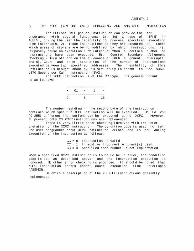
ASSIST4-2 B. THE XOPC (OPTIONS CALL) DEBUGGING AND ANALYSIS INSTRUCTION The OPtions Call pseudo-instruction can provide the user programmer with several functions: 1). Set a type of 'SPIE' in ASSIST, giving the user the capability to process specified execution time interrupts, 2). Trace instructions as they are executed, 3). Check which areas of storage are being modified by which instructions, 4). Purposely cause an execution time interrupt when a certain number of instructions have been executed, 5). Control Boundary Alignment Checking - Turn off and on the allowance of S0C6 alignment interrupts, and 6). Count and print statistics of the number of instructions executed between two specified addresses. The flexibility of this instruction is brought about by its similarity in format to the s360- s370 Supervisor Call Instruction (SVC). The XOPC instruction is of the RR type. Its general format is as follows: -------------------- × 01 × I1 × -------------------- 0 8 15 The number residing in the second byte of the instruction controls which specific XOPC instruction will be executed. Up to 256 (0-255) different instructions can be executed using XOPC. However, at present only 23 XOPC instructions are implemented. There is very little error checking involved with the inter- pretation of the XOPC instruction. The condition code is used to tell the user programmer about XOPC instruction errors and is set during execution of the instruction as follows: CC = 0 Instruction is valid CC = 1 Illegal or Incorrect Argument(s) used. CC = 3 Specified code number is not implemented. When a specified XOPC instruction is found to be in error, the condition code is set as described above, and the instruction execution is ignored. No other error checking is provided. It should be noted that XOPC instruction errors cannot cause execution time interrupts (ABENDS). Below is a description of the 23 XOPC instructions presently implemented.

ASSIST4-3 XOPC 0 - SET PSEUDO - SPIE EXIT ADDRESS This instruction allows the user to set a type of 'SPIE'. The user specifies an address and the interrupts he wishes to process in a coded form. When this instruction is executed, Registers 0 and 1 are assumed to contain certain arguments. Register 1 must contain a user program address (Exit Address) to which control is passed if any of the specified program interrupts occur. The last 15 bits (bits 17-31) of Register 0 must contain a code specifying which interrupts the user wishes to intercept. The first 17 bits of register 0 are ignored. Each of the bit positions 17 to 31 of register 0 correspond to one of the 15 execution time interrupts. A 1 in one of the bit positions specifies a spie-exit on the corresponding program interrupt. For example, Bit (17) = 1 specifies a spie-exit on S0C1, Bit (18) = 1 specifies a spie-exit on S0C2, ......., Bit (31) = 1 specifies a spie-exit on S0CF. A zero in any of the bit positions allows the corresponding execution time interrupt to occur as if no spie had been set. Example: If register 0 contains the following; 0000 0000 0000 0000 0111 0000 0000 0001 After an XOPC 0 instruction has been executed with register 0 as above, control will be passed to the address found in register 1 if any of the following interrupts occur; S0C1, S0C2, S0C3 and S0CF. If a spie exit address has been given (i.e. This instruction has been executed) and one of the specified interrupts occurs, the following actions take place: 1). The current values of user register 0 and 1 are saved. 2). The PSW at interrupt is loaded into registers 0 and 1. 3). The proper interrupt code is inserted into user register 0 (bits 17 thru 31 of the PSW). 4). ASSIST now considers the user in the interrupt processing state. 5). Control in the user program is passed to the given interrupt exit address. It should be noted that when the user is in the Interrupt Processing State any further interrupt will cause abnormal termination of the user program. The user will remain in this state until the exec- ution of an XOPC 21 instruction. XOPC 0 can be executed an unlimited number of times during the execution of a program to change the specified exit address or to change the interrupts to be intercepted. Note, however, that the most recent execution of XOPC 0 is the one in effect, and cancels all previous executions.
ASSIST4-4 XOPC 1 - SET ADDRESSES FOR THE INSTRUCTION TRACE FACILITY This instruction specifies boundary addresses used by the trace facility. Once enabled the trace facility will give the user a printed trace of all instructions executed within these two boundary addresses. When this instruction is executed the lower and upper trace address limits are assumed to be in registers 0 and 1, respectively. XOPC 2 - TURN ON THE INSTRUCTION TRACE FACILITY This instruction enables the trace facility. Prior to the execution of this instruction the user should have specified two limit addresses. However, if no limit addresses have been specified, ASSIST will use the highest and lowest program addresses for the limits. Below is an example of the trace line printed for each instruction executed. Assume this instruction is executed causing the following trace message to be printed: ADDR INSTRUCTION 00EBE0 STM R0,R10,SAVEAREA Here is the trace message printed: TRACE--> INSTR ADDR: 00EBE0 INSTR: 980A 6020 XOPC 3 - SET ADDRESSES (as in XOPC 1) and TURN ON THE INSTRUCTION TRACE FACILITY This instruction combines the actions of XOPC instructions 1 and 2. It assumes register usage the same as in XOPC 1. XOPC 4 - TURN OFF THE INSTRUCTION TRACE FACILITY This instruction disables the Instruction Trace. XOPC 5 - SET ADDRESSES FOR THE STORAGE MODIFICATION CHECKING FACILITY This instruction specifies address boundaries (high and low) inside which the Storage Modification Checking Facility will operate. Once enabled, this facility causes storage between the boundary addresses to be monitored. If any of this storage is modified, the length of storage modified and the instruction modifying the storage will be printed for the user. The register usage upon execution of this instruction is the same as in XOPC 1 above.
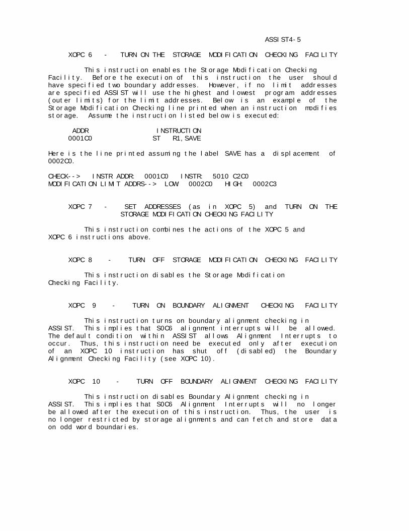
ASSIST4-5 XOPC 6 - TURN ON THE STORAGE MODIFICATION CHECKING FACILITY This instruction enables the Storage Modification Checking Facility. Before the execution of this instruction the user should have specified two boundary addresses. However, if no limit addresses are specified ASSIST will use the highest and lowest program addresses (outer limits) for the limit addresses. Below is an example of the Storage Modification Checking line printed when an instruction modifies storage. Assume the instruction listed below is executed: ADDR INSTRUCTION 0001C0 ST R1,SAVE Here is the line printed assuming the label SAVE has a displacement of 0002C0. CHECK--> INSTR ADDR: 0001C0 INSTR: 5010 C2C0 MODIFICATION LIMIT ADDRS--> LOW: 0002C0 HIGH: 0002C3 XOPC 7 - SET ADDRESSES (as in XOPC 5) and TURN ON THE STORAGE MODIFICATION CHECKING FACILITY This instruction combines the actions of the XOPC 5 and XOPC 6 instructions above. XOPC 8 - TURN OFF STORAGE MODIFICATION CHECKING FACILITY This instruction disables the Storage Modification Checking Facility. XOPC 9 - TURN ON BOUNDARY ALIGNMENT CHECKING FACILITY This instruction turns on boundary alignment checking in ASSIST. This implies that S0C6 alignment interrupts will be allowed. The default condition within ASSIST allows Alignment Interrupts to occur. Thus, this instruction need be executed only after execution of an XOPC 10 instruction has shut off (disabled) the Boundary Alignment Checking Facility (see XOPC 10). XOPC 10 - TURN OFF BOUNDARY ALIGNMENT CHECKING FACILITY This instruction disables Boundary Alignment checking in ASSIST. This implies that S0C6 Alignment Interrupts will no longer be allowed after the execution of this instruction. Thus, the user is no longer restricted by storage alignments and can fetch and store data on odd word boundaries.
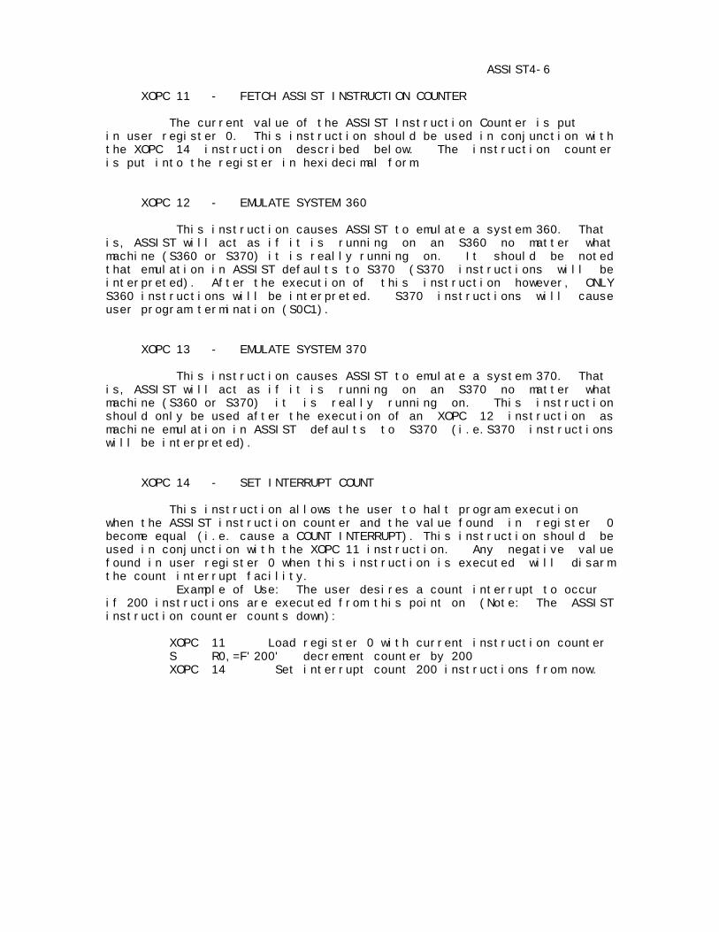
ASSIST4-6 XOPC 11 - FETCH ASSIST INSTRUCTION COUNTER The current value of the ASSIST Instruction Counter is put in user register 0. This instruction should be used in conjunction with the XOPC 14 instruction described below. The instruction counter is put into the register in hexidecimal form. XOPC 12 - EMULATE SYSTEM 360 This instruction causes ASSIST to emulate a system 360. That is, ASSIST will act as if it is running on an S360 no matter what machine (S360 or S370) it is really running on. It should be noted that emulation in ASSIST defaults to S370 (S370 instructions will be interpreted). After the execution of this instruction however, ONLY S360 instructions will be interpreted. S370 instructions will cause user program termination (S0C1). XOPC 13 - EMULATE SYSTEM 370 This instruction causes ASSIST to emulate a system 370. That is, ASSIST will act as if it is running on an S370 no matter what machine (S360 or S370) it is really running on. This instruction should only be used after the execution of an XOPC 12 instruction as machine emulation in ASSIST defaults to S370 (i.e.S370 instructions will be interpreted). XOPC 14 - SET INTERRUPT COUNT This instruction allows the user to halt program execution when the ASSIST instruction counter and the value found in register 0 become equal (i.e. cause a COUNT INTERRUPT). This instruction should be used in conjunction with the XOPC 11 instruction. Any negative value found in user register 0 when this instruction is executed will disarm the count interrupt facility. Example of Use: The user desires a count interrupt to occur if 200 instructions are executed from this point on (Note: The ASSIST instruction counter counts down): XOPC 11 Load register 0 with current instruction counter S R0,=F'200' decrement counter by 200 XOPC 14 Set interrupt count 200 instructions from now.

ASSIST4-7 XOPC 15 - SET COUNT EXIT ADDRESS The value found in user register 0 when this instruction is executed will be used as an exit address if a count interrupt occurs (i.e. when the instruction counter becomes equal to the clock comparator - see XOPC 14). If a count interrupt occurs after this instruction has been executed, the psw at interrupt will be loaded into user registers 0 and 1. Execution will then continue beginning at the given exit address. If no exit address has been specified and a count interrupt occurs, the program abnormally terminates with the standard ASSIST instruction limit exceeded error printed. XOPC 16 - TURN ON THE INSTRUCTION EXECUTION COUNT FACILITY This instruction enables the INSTRUCTION EXECUTION COUNT FACILITY. This facility counts each instruction executed between two limit addresses. It should be realized that upon its initial execution this instruction will cause ASSIST to allocate a section of main memory equal in size to that of the user program. If this space is found to be unavailable, the condition code of the user program is set to one and the count facility remains disabled. Prior to the execution of this instruction, the user should have specified two limit addresses for the count facility (See XOPC 17 below). However, if two limit addresses were not specified, ASSIST will use the highest and lowest program addresses for the limit addresses. Note: This instruction does not clear the instruction counting area. See XOPC 20 for clearing the count area. XOPC 17 - SET ADDRESSES FOR THE INSTRUCTION EXECUTION COUNT FACILITY (IECF) This instruction specifies boundary limit addresses used by IECF. Once enabled this facility will count the number of executions of each instruction between the two limit addresses specified by this instruction. When this instruction is executed the low and high IECF limit addresses are assumed to be in registers 0 and 1, respectively. XOPC 18 - SET ADDRESSES AND TURN ON THE IECF This instruction combines the actions of XOPC instructions 16 and 17. Register usage is assumed to be the same as in XOPC 17. XOPC 19 - TURN OFF THE INSTRUCTION EXECUTION COUNT FACILITY This instruction disables the IECF. This instruction will not have any effect on the IECF counting area.

ASSIST4-8 XOPC 20 - CLEAR THE INSTRUCTION EXECUTION COUNT FACILITY COUNTING AREA This instruction resets the Instruction Execution Count Facility Counting area to zero. If the IECF has never been enabled in the user program (i.e. no counting space has been allocated), the condition code of the user program is set to 1 and this instruction is ignored. This instruction can be executed an unlimited number of times to insure accurate instruction counting. Please note that the counter for each instruction is only a halfword (2 bytes) in length. Executing one instruction many times could overflow that counter and reset it to zero. XOPC 21 - RETURN FROM INTERRUPT PROCESSING CODE This instruction tells ASSIST that the User Program has com- pleted any interrupt processing routine (s) and is ready to resume normal execution of the user program. It causes the following actions to occur: 1). If the user is not in the interrupt processing state the condition code is set to 1 and nothing more is done. 2). The address in register 1 is used as the address where normal execution of the user program will resume. If register 1 is not modified in the interrupt processing code, execution of the user program will continue with the instruction immediately following the instruction that caused the initial interrupt. Otherwise, the user will be expected to load register 1 with an appropriate address. 3). User registers 0 and 1 are reloaded with the values they had when the initial interrupt occurred. 4). Normal execution of the user program is resumed with the user no longer in the INTERRUPT PROCESSING STATE. XOPC 22 - DUMP THE INSTRUCTION EXECUTION COUNT FACILITY STATISTICS This instruction prints out a statistical report according to address of the number of instructions counted (within the specified limit addresses) by the Instruction Execution Count Facility. An instruction executed 0 times will cause no statistical line to be printed. Groups of instructions executed the same number of times will produce one statistical line. This shows the user where his major loops are and where most of his execution time is being spent. If this instruction is executed and the count facility has not yet been enabled at least once in the user program (i.e. no count space has been allocated), the condition code of the user program is set to one and this instruction is ignored. As an example consider the following test program:
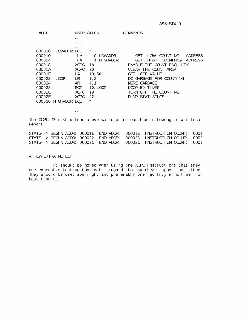
ASSIST4-9 ADDR INSTRUCTION COMMENTS ... ... ... 000010 LOWADDR EQU * 000010 LA 0,LOWADDR GET LOW COUNTING ADDRESS 000014 LA 1,HIGHADDR GET HIGH COUNTING ADDRESS 000018 XOPC 18 ENABLE THE COUNT FACILITY 00001A XOPC 20 CLEAR THE COUNT AREA 00001E LA 10,50 GET LOOP VALUE 000022 LOOP LR 1,3 DO GARBAGE FOR COUNTING 000024 AR 4,1 MORE GARBAGE 000028 BCT 10,LOOP LOOP 50 TIMES 00002C XOPC 19 TURN OFF THE COUNTING 00002E XOPC 22 DUMP STATISTICS 000030 HIGHADDR EQU * ... ... ... The XOPC 22 instruction above would print out the following statistical report: STATS--> BEGIN ADDR: 00001E END ADDR: 00001E INSTRUCTION COUNT: 0001 STATS--> BEGIN ADDR: 000022 END ADDR: 000028 INSTRUCTION COUNT: 0050 STATS--> BEGIN ADDR: 00002C END ADDR: 00002C INSTRUCTION COUNT: 0001 A FEW EXTRA NOTES: It should be noted when using the XOPC instructions that they are expensive instructions with regard to overhead space and time. They should be used sparingly and preferably one facility at a time for best results.
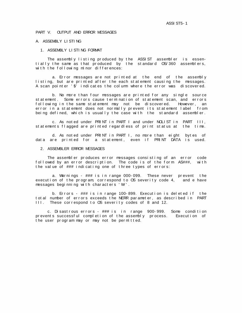
ASSIST5-1 PART V. OUTPUT AND ERROR MESSAGES A. ASSEMBLY LISTING 1. ASSEMBLY LISTING FORMAT The assembly listing produced by the ASSIST assembler is essen- tially the same as that produced by the standard OS/360 assemblers, with the following minor differences: a. Error messages are not printed at the end of the assembly listing, but are printed after the each statement causing the messages. A scan pointer '$' indicates the column where the error was discovered. b. No more than four messages are printed for any single source statement. Some errors cause termination of statement scan, and errors following in the same statement may not be discovered. However, an error in a statement does not normally prevent its statement label from being defined, which is usually the case with the standard assembler. c. As noted under PRINT in PART I and under NOLIST in PART III, statements flagged are printed regardless of print status at the time. d. As noted under PRINT in PART I, no more than eight bytes of data are printed for a statement, even if PRINT DATA is used. 2. ASSEMBLER ERROR MESSAGES The assembler produces error messages consisting of an error code followed by an error description. The code is of the form AS###, with the value of ### indicating one of three types of errors: a. Warnings - ### is in range 000-099. These never prevent the execution of the program, correspond to OS severity code 4, and e have messages beginning with characters 'W-'. b. Errors - ### is in range 100-899. Execution is deleted if the total number of errors exceeds the NERR parameter, as described in PART III. These correspond to OS severity codes of 8 and 12. c. Disastrous errors - ### is in range 900-999. Some condition prevents successful completion of the assembly process. Execution of the user program may or may not be permitted.

ASSIST5-2 3. LIST OF ASSEMBLER ERROR MESSAGES The following lists the codes and messages issued by the ASSIST assembler, with further explanations following each message. AS000 W-ALIGNMENT ERROR-IMPROPER BOUNDARY The address used in a machine instruction is not aligned to the correct boundary required by the type of instruction used. AS001 W-ENTRY ERROR-CONFLICT OR UNDEFINED A symbol named in an ENTRY statement is either undefined, or is also named in either a DSECT or EXTRN statement. AS002 W-EXTERNAL NAME ERROR OR CONFLICT A symbol named in an EXTRN statement is either defined in the program or is named in an ENTRY statement. AS003 W-REGISTER NOT USED The register flagged in a DROP statement is not available for use as a base register at this point in the program. This may be caused by an error in a USING statement naming the register. AS004 W-ODD REGISTER USED-EVEN REQUIRED An odd register is coded in a machine instruction requiring the use of an even register for a specific operand. Instructions which may flagged are Multiply, Divide, Double Shifts, and all floating point instructions. AS005 W-END CARD MISSING-SUPPLIED The assembler creates an END card because the user has supplied none before an end-file marker.

ASSIST5-3 AS100 ADDRESSIBILITY ERROR An implied address is used which cannot be resolved into base- displacement form. No base register is available having the same relocatability attribute and a value from 0 to 4095 less than the value of the implied address. AS101 CONSTANT TOO LONG Too many characters are coded for the type of constant specified. This message appears if a literal constant contains more than 112 characters, including the equals sign and delimiters. AS102 ILLEGAL CONSTANT TYPE An unrecognizable type of constant is specified. AS103 CONTINUATION CARD COLS. 1-15 NONBLANK A continuation card contains nonblank characters in columns 1-15. This may be caused by an accidental punch in column 72 of the preceding card. AS104 MORE THAN 2 CONTINUATION CARDS Three or more continuation cards are used, which is illegal, except on macro prototype statements and macro calls. AS105 COMPLEX RELOCATABILITY ILLEGAL ASSIST does not permit complex relocatible expressions. AS106 TOO MANY OPERANDS IN DC ASSIST allows no more than ten operands in a DC statement. AS107 MAY NOT RESUME SECTION CODING The assembler requires that any section be coded in one piece. The label flagged has already appeared on a CSECT or DSECT. AS108 ILLEGAL DUPLICATION FACTOR A duplication factor either exceeds the maximum value of 32,767, or a duplication factor in a literal constant is not specified by a decimal term or else has the value zero. AS109 EXPRESSION TOO LARGE The value of the flagged expression or term is too large for the given usage, such as a constant length greater than the maximum permissible for the type of constant. AS110 EXPRESSION TOO SMALL The value of the flagged expression or term is too small for the given usage, or has a negative value. Coding a V-type constant with a length of two would generate this message.
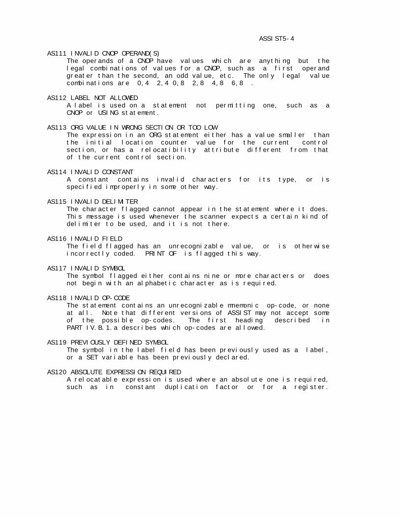
ASSIST5-4 AS111 INVALID CNOP OPERAND(S) The operands of a CNOP have values which are anything but the legal combinations of values for a CNOP, such as a first operand greater than the second, an odd value, etc. The only legal value combinations are 0,4 2,4 0,8 2,8 4,8 6,8 . AS112 LABEL NOT ALLOWED A label is used on a statement not permitting one, such as a CNOP or USING statement. AS113 ORG VALUE IN WRONG SECTION OR TOO LOW The expression in an ORG statement either has a value smaller than the initial location counter value for the current control section, or has a relocatibility attribute different from that of the current control section. AS114 INVALID CONSTANT A constant contains invalid characters for its type, or is specified improperly in some other way. AS115 INVALID DELIMITER The character flagged cannot appear in the statement where it does. This message is used whenever the scanner expects a certain kind of delimiter to be used, and it is not there. AS116 INVALID FIELD The field flagged has an unrecognizable value, or is otherwise incorrectly coded. PRINT OF is flagged this way. AS117 INVALID SYMBOL The symbol flagged either contains nine or more characters or does not begin with an alphabetic character as is required. AS118 INVALID OP-CODE The statement contains an unrecognizable mnemonic op-code, or none at all. Note that different versions of ASSIST may not accept some of the possible op-codes. The first heading described in PART IV.B.1.a describes which op-codes are allowed. AS119 PREVIOUSLY DEFINED SYMBOL The symbol in the label field has been previously used as a label, or a SET variable has been previously declared. AS120 ABSOLUTE EXPRESSION REQUIRED A relocatable expression is used where an absolute one is required, such as in constant duplication factor or for a register.
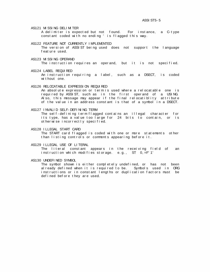
ASSIST5-5 AS121 MISSING DELIMITER A delimiter is expected but not found. For instance, a C-type constant coded with no ending ' is flagged this way. AS122 FEATURE NOT CURRENTLY IMPLEMENTED The version of ASSIST being used does not support the language feature used. AS123 MISSING OPERAND The instruction requires an operand, but it is not specified. AS124 LABEL REQUIRED An instruction requiring a label, such as a DSECT, is coded without one. AS126 RELOCATABLE EXPRESSION REQUIRED An absolute expression or term is used where a relocatable one is required by ASSIST, such as in the first operand of a USING. Also, this message may appear if the final relocatiblity attribute of the value in an address constant is that of a symbol in a DSECT. AS127 INVALID SELF-DEFINING TERM The self-defining term flagged contains an illegal character for its type, has a value too large for 24 bits to contain, or is otherwise incorrectly specified. AS128 ILLEGAL START CARD The START card flagged is coded with one or more statements other than listing controls or comments appearing before it. AS129 ILLEGAL USE OF LITERAL The literal constant appears in the receiving field of an instruction which modifies storage. e.g., ST 0,=F'1' AS130 UNDEFINED SYMBOL The symbol shown is either completely undefined, or has not been already defined when it is required to be. Symbols used in ORG instructions or in constant lengths or duplication factors must be defined before they are used.

ASSIST5-6 AS131 UNRESOLVED EXTERNAL REFERENCE The symbol used in a V-type constant is not defined in the assembly, or is defined but not declared a CSECT or ENTRY. ASSIST does not link multiple assemblies, so this is an error. AS132 ILLEGAL CHARACTER The character flagged is either not in the set of acceptable characters, or is used in an illegal way. AS133 TOO MANY PARENTHESIS LEVELS Parentheses are nested more than five deep in an expression. AS134 RELOCATABLE EXPRESSION USED WITH * OR / RElocatable terms or expressions may not be used with either of these operators. AS135 SYNTAX The character flagged is improperly used. This catchall message is given by the general expression evaluator when it does not find what is expected during a scan. AS136 TOO MANY TERMS IN EXPRESSION The expression contains more than the legal maximum of 16 terms. AS137 UNEXPECTED END OF EXPRESSION The expression terminates without having enough closing parentheses to balance the opening ones used. THE FOLLOWING MESSAGES ARE ONLY ISSUED DURING MACRO PROCESSING. AS201 OPERAND NOT ALLOWED During macro expansion, an extra operand was found, i.e., an extra positional beyond those given in the prototype. AS202 STATEMENT OUT OF ORDER The statement flagged is in an incorrect place in the deck. For example: LCLx before GBLx, ACTR not after both; GBLx, LCLx, ACTR in middle of macro definition or open code. *SYSLIB card out of order, etc. May often be caused by missing MEND card. AS203 SET SYMBOL DIMENSION ERROR A dimensioned set symbol was used without a dimension, or one which was not dimensioned was written with one. AS204 INVALID NBR OF SUBSCRIPTS There was an error in specifying substring notation, sublists, or set symbol dimension.
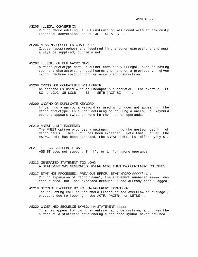
ASSIST5-7 AS205 ILLEGAL CONVERSION During macro editing, a SET instruction was found with an obviously Incorrect conversion, as in &I SETA C . AS206 MISSING QUOTES IN CHAR EXPR Quotes (apostrophes) are required in character expressions and must always be supplied, but were not. AS207 ILLEGAL OR DUP MACRO NAME A macro prototype name is either completely illegal, such as having too many characters, or duplicates the name of a previously given macro, machine instruction, or assembler instruction. AS208 OPRND NOT COMPATIBLE WITH OPRTR An operand is used with an incompatible operator. For example, if &C is LCLC, &B LCLB : &B SETB (NOT &C) . AS209 UNDFND OR DUPLICATE KEYWORD In calling a macro, a keyword is used which does not appear in the macro prototype. In either defining or calling a macro, a keyword operand appears twice or more in the list of operands. AS210 MNEST LIMIT EXCEEDED The MNEST option provides a maximum limit to the nested depth of macro calls. This limit has been exceeded. Note that after the MSTMG limit has been exceeded, the MNEST limit is effectively 0 . AS211 ILLEGAL ATTRIBUTE USE ASSIST does not support S', I', or L' for macro operands. AS212 GENERATED STATEMENT TOO LONG A STATEMENT WAS GENERATED HAVING MORE THAN TWO CONTINUATION CARDS . AS217 STMT NOT PROCESSED: PREVIOUS ERROR: STMT/MACRO #####/name During expansion of macro 'name', the statement numbered ##### was encountered, but not expanded because it had already been flagged. AS218 STORAGE EXCEEDED BY FOLLOWING MACRO EXPANSION The following call to the macro listed caused overflow of storage , probably due to looping. Use ACTR, MACTR=, or MSTMG= . AS220 UNDEFINED SEQUENCE SYMBOL IN STATEMENT ##### This may appear following an entire macro definition, and gives the number of a statement referencing a sequence symbol never defined .
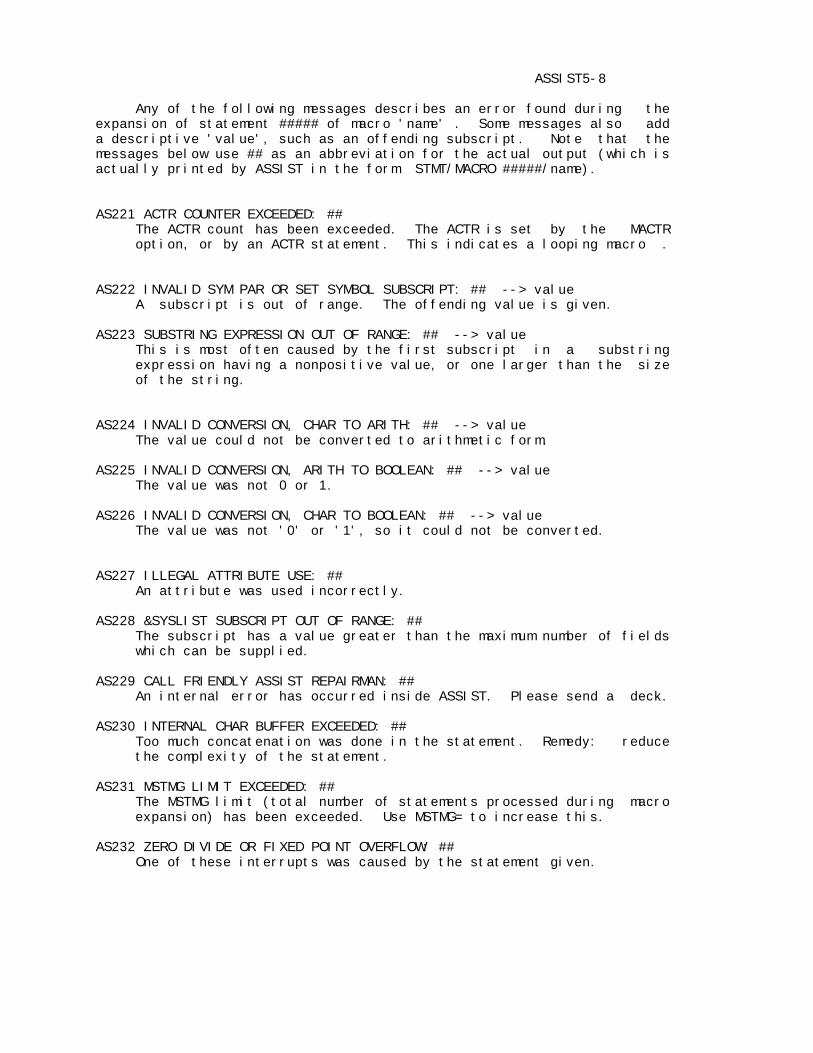
ASSIST5-8 Any of the following messages describes an error found during the expansion of statement ##### of macro 'name' . Some messages also add a descriptive 'value', such as an offending subscript. Note that the messages below use ## as an abbreviation for the actual output (which is actually printed by ASSIST in the form STMT/MACRO #####/name). AS221 ACTR COUNTER EXCEEDED: ## The ACTR count has been exceeded. The ACTR is set by the MACTR option, or by an ACTR statement. This indicates a looping macro . AS222 INVALID SYM PAR OR SET SYMBOL SUBSCRIPT: ## --> value A subscript is out of range. The offending value is given. AS223 SUBSTRING EXPRESSION OUT OF RANGE: ## --> value This is most often caused by the first subscript in a substring expression having a nonpositive value, or one larger than the size of the string. AS224 INVALID CONVERSION, CHAR TO ARITH: ## --> value The value could not be converted to arithmetic form. AS225 INVALID CONVERSION, ARITH TO BOOLEAN: ## --> value The value was not 0 or 1. AS226 INVALID CONVERSION, CHAR TO BOOLEAN: ## --> value The value was not '0' or '1', so it could not be converted. AS227 ILLEGAL ATTRIBUTE USE: ## An attribute was used incorrectly. AS228 &SYSLIST SUBSCRIPT OUT OF RANGE: ## The subscript has a value greater than the maximum number of fields which can be supplied. AS229 CALL FRIENDLY ASSIST REPAIRMAN: ## An internal error has occurred inside ASSIST. Please send a deck. AS230 INTERNAL CHAR BUFFER EXCEEDED: ## Too much concatenation was done in the statement. Remedy: reduce the complexity of the statement. AS231 MSTMG LIMIT EXCEEDED: ## The MSTMG limit (total number of statements processed during macro expansion) has been exceeded. Use MSTMG= to increase this. AS232 ZERO DIVIDE OR FIXED POINT OVERFLOW: ## One of these interrupts was caused by the statement given.
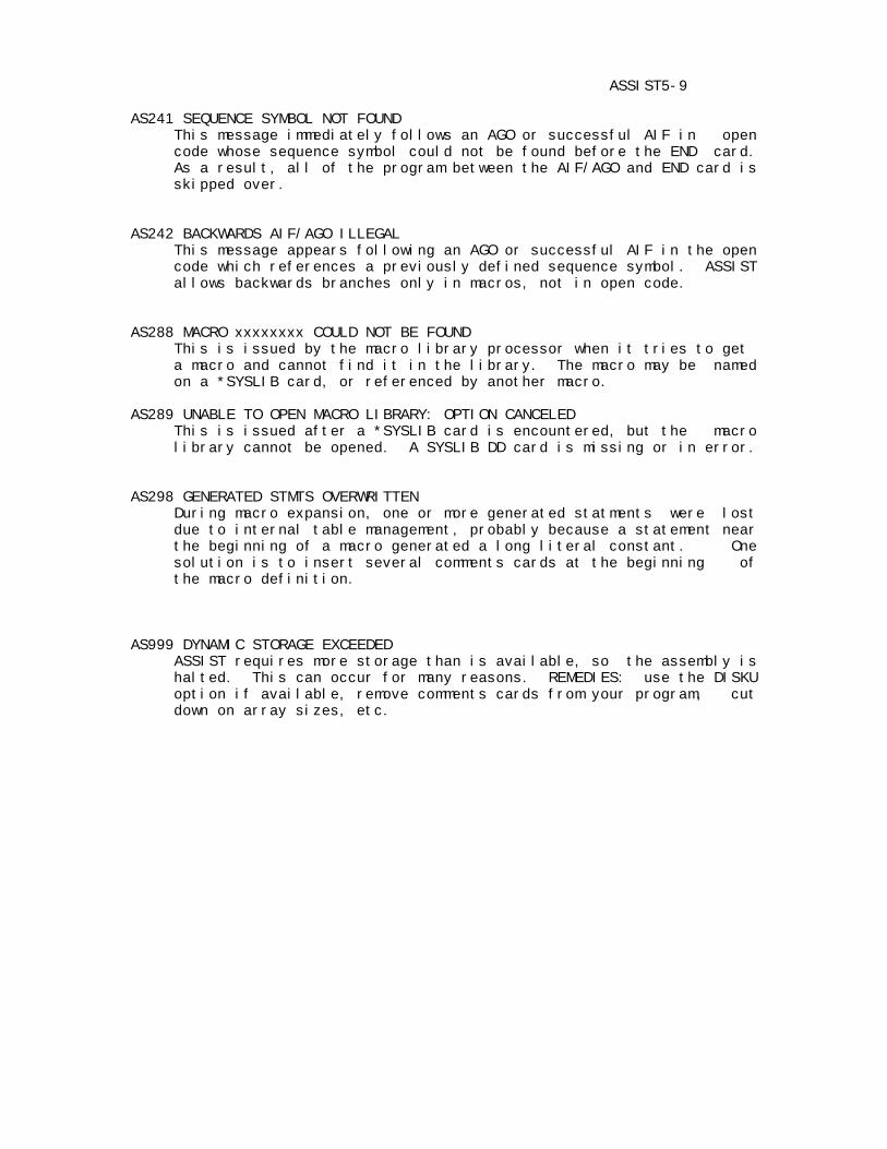
ASSIST5-9 AS241 SEQUENCE SYMBOL NOT FOUND This message immediately follows an AGO or successful AIF in open code whose sequence symbol could not be found before the END card. As a result, all of the program between the AIF/AGO and END card is skipped over. AS242 BACKWARDS AIF/AGO ILLEGAL This message appears following an AGO or successful AIF in the open code which references a previously defined sequence symbol. ASSIST allows backwards branches only in macros, not in open code. AS288 MACRO xxxxxxxx COULD NOT BE FOUND This is issued by the macro library processor when it tries to get a macro and cannot find it in the library. The macro may be named on a *SYSLIB card, or referenced by another macro. AS289 UNABLE TO OPEN MACRO LIBRARY: OPTION CANCELED This is issued after a *SYSLIB card is encountered, but the macro library cannot be opened. A SYSLIB DD card is missing or in error. AS298 GENERATED STMTS OVERWRITTEN During macro expansion, one or more generated statments were lost due to internal table management, probably because a statement near the beginning of a macro generated a long literal constant. One solution is to insert several comments cards at the beginning of the macro definition. AS999 DYNAMIC STORAGE EXCEEDED ASSIST requires more storage than is available, so the assembly is halted. This can occur for many reasons. REMEDIES: use the DISKU option if available, remove comments cards from your program, cut down on array sizes, etc.

ASSIST5-10 4. ASSEMBLER STATISTICS SUMMARY Following the assembly listing, the assembler prints three or four lines of statistical information, as follows: a. *** ##### STATEMENTS FLAGGED - ##### WARNINGS, ##### ERRORS This notes the total numbers of statements flagged, warning messages, and error messages given during the assembly. b. ***** NUMBER OF ERRORS EXCEEDS LIMIT OF ##### ERRORS - PROGRAM EXECUTION DELETED ***** This notes the maximum number of errors permitting execution, and that the user program will not be executed because the NERR limit value has been overrun (see PART III regarding NERR). c. *** DYNAMIC CORE AREA USED: LOW: ###### HIGH: ###### LEAVING: ###### FREE BYTES. AVERAGE: ###### BYTES/STMT *** The ASSIST assembler uses memory from the opposite ends of one area of storage acquired at execution time. The LOW area contains source statements and generated object code,the HIGH area contains the symbol and literal tables, and the space remaining indicates how close the user is to causing a storage overflow. The average core usage printed includes that used in both LOW and HIGH areas. d. *** ASSEMBLY TIME = #.### SECS, ##### STATEMENTS/SEC *** This notes the total time used by the assembler, along with the rate of assembly. At PSU, this time includes both CPU time and I/O charges. e. ***** EXECUTION DELETED - LESS THAN ## PER CENT OF MACHINE INSTRUCTIONS HAVE COMMENTS ***** The above message may appear before the core area message, if the ASSIST has the comment-checking option, and either COMNT was coded, or was invoked by account number, and the user did not put comments on the given percentage of machine instruction statements.
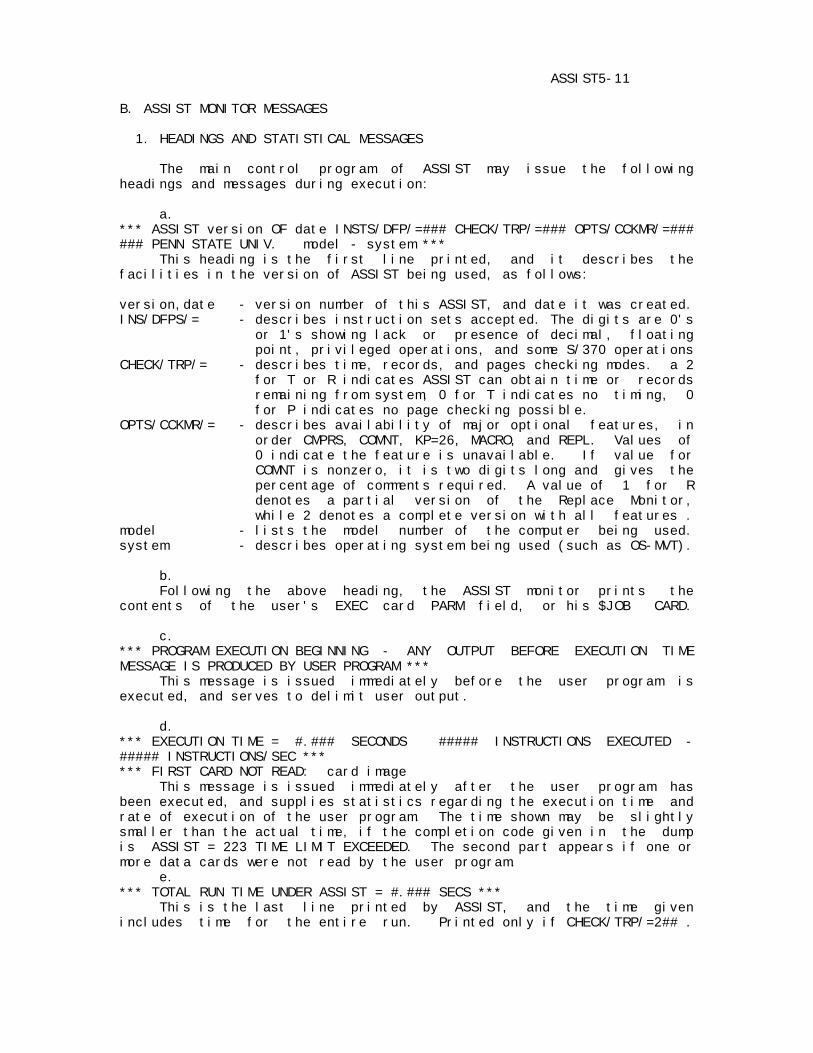
ASSIST5-11 B. ASSIST MONITOR MESSAGES 1. HEADINGS AND STATISTICAL MESSAGES The main control program of ASSIST may issue the following headings and messages during execution: a. *** ASSIST version OF date INSTS/DFP/=### CHECK/TRP/=### OPTS/CCKMR/=### ### PENN STATE UNIV. model - system *** This heading is the first line printed, and it describes the facilities in the version of ASSIST being used, as follows: version,date - version number of this ASSIST, and date it was created. INS/DFPS/= - describes instruction sets accepted. The digits are 0's or 1's showing lack or presence of decimal, floating point, privileged operations, and some S/370 operations CHECK/TRP/= - describes time, records, and pages checking modes. a 2 for T or R indicates ASSIST can obtain time or records remaining from system, 0 for T indicates no timing, 0 for P indicates no page checking possible. OPTS/CCKMR/= - describes availability of major optional features, in order CMPRS, COMNT, KP=26, MACRO, and REPL. Values of 0 indicate the feature is unavailable. If value for COMNT is nonzero, it is two digits long and gives the percentage of comments required. A value of 1 for R denotes a partial version of the Replace Monitor, while 2 denotes a complete version with all features . model - lists the model number of the computer being used. system - describes operating system being used (such as OS-MVT). b. Following the above heading, the ASSIST monitor prints the contents of the user's EXEC card PARM field, or his $JOB CARD. c. *** PROGRAM EXECUTION BEGINNING - ANY OUTPUT BEFORE EXECUTION TIME MESSAGE IS PRODUCED BY USER PROGRAM *** This message is issued immediately before the user program is executed, and serves to delimit user output. d. *** EXECUTION TIME = #.### SECONDS ##### INSTRUCTIONS EXECUTED - ##### INSTRUCTIONS/SEC *** *** FIRST CARD NOT READ: card image This message is issued immediately after the user program has been executed, and supplies statistics regarding the execution time and rate of execution of the user program. The time shown may be slightly smaller than the actual time, if the completion code given in the dump is ASSIST = 223 TIME LIMIT EXCEEDED. The second part appears if one or more data cards were not read by the user program. e. *** TOTAL RUN TIME UNDER ASSIST = #.### SECS *** This is the last line printed by ASSIST, and the time given includes time for the entire run. Printed only if CHECK/TRP/=2## .

ASSIST5-12 2. ASSIST MONITOR ERROR MESSAGES The ASSIST monitor may also issue any of the following messages, which are of the form AM###, and usually indicate errors: AM001 ASSIST COULD NOT OPEN PRINTER FT06F001:ABORT This message appears in the system message class data set if ASSIST is unable to open the DCB for its printer, using DDNAME FT06F001. This is probably caused by lack of a DD card, or by an incorrect override of this DDNAME in a catalogued procedure. AM002 ASSIST COULD NOT OPEN READER SYSIN:ABORT This message appears in the system message class data set if ASSIST is unable to open the DCB for the source card reader. The SYSIN DD * card is probably omitted or mispunched, making an assembly and execution impossible. AM003 - STORAGE OVERFLOW BEFORE EXECUTION, EXECUTION DELETED The user program assembled properly, but there is insufficient memory remaining to set up control blocks required for execution. The user should attempt to reduce the amount of storage used by his program. This message should occur very seldom. AM004 - NORMAL USER TERMINATION BY RETURN This message is issued if the user program branches to the address originally supplied to it as a return address in register 14. If this message appears, no completion dump is printed. AM005 - TIME OR RECORDS HAVE BEEN EXCEEDED This message is printed if the time or record limits have been exceeded at any time during a job. This message appears after a completion dump, if there is one.
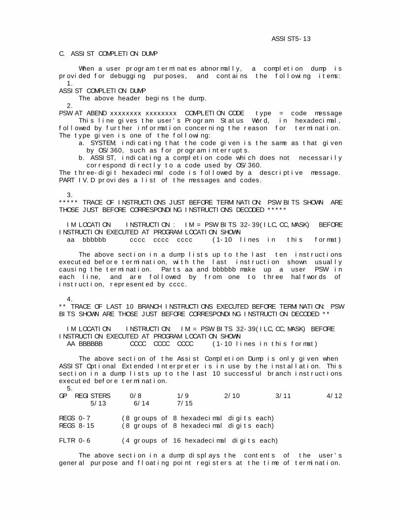
ASSIST5-13 C. ASSIST COMPLETION DUMP When a user program terminates abnormally, a completion dump is provided for debugging purposes, and contains the following items: 1. ASSIST COMPLETION DUMP The above header begins the dump. 2. PSW AT ABEND xxxxxxxx xxxxxxxx COMPLETION CODE type = code message This line gives the user's Program Status Word, in hexadecimal, followed by further information concerning the reason for termination. The type given is one of the following: a. SYSTEM, indicating that the code given is the same as that given by OS/360, such as for program interrupts. b. ASSIST, indicating a completion code which does not necessarily correspond directly to a code used by OS/360. The three-digit hexadecimal code is followed by a descriptive message. PART IV.D provides a list of the messages and codes. 3. ***** TRACE OF INSTRUCTIONS JUST BEFORE TERMINATION: PSW BITS SHOWN ARE THOSE JUST BEFORE CORRESPONDING INSTRUCTIONS DECODED ***** IM LOCATION INSTRUCTION : IM = PSW BITS 32-39(ILC,CC,MASK) BEFORE INSTRUCTION EXECUTED AT PROGRAM LOCATION SHOWN aa bbbbbb cccc cccc cccc (1-10 lines in this format) The above section in a dump lists up to the last ten instructions executed before termination, with the last instruction shown usually causing the termination. Parts aa and bbbbbb make up a user PSW in each line, and are followed by from one to three halfwords of instruction, represented by cccc. 4. ** TRACE OF LAST 10 BRANCH INSTRUCTIONS EXECUTED BEFORE TERMINATION: PSW BITS SHOWN ARE THOSE JUST BEFORE CORRESPONDING INSTRUCTION DECODED ** IM LOCATION INSTRUCTION: IM = PSW BITS 32-39(ILC,CC,MASK) BEFORE INSTRUCTION EXECUTED AT PROGRAM LOCATION SHOWN AA BBBBBB CCCC CCCC CCCC (1-10 lines in this format) The above section of the Assist Completion Dump is only given when ASSIST Optional Extended Interpreter is in use by the installation. This section in a dump lists up to the last 10 successful branch instructions executed before termination. 5. GP REGISTERS 0/8 1/9 2/10 3/11 4/12 5/13 6/14 7/15 REGS 0-7 (8 groups of 8 hexadecimal digits each) REGS 8-15 (8 groups of 8 hexadecimal digits each) FLTR 0-6 (4 groups of 16 hexadecimal digits each) The above section in a dump displays the contents of the user's general purpose and floating point registers at the time of termination.
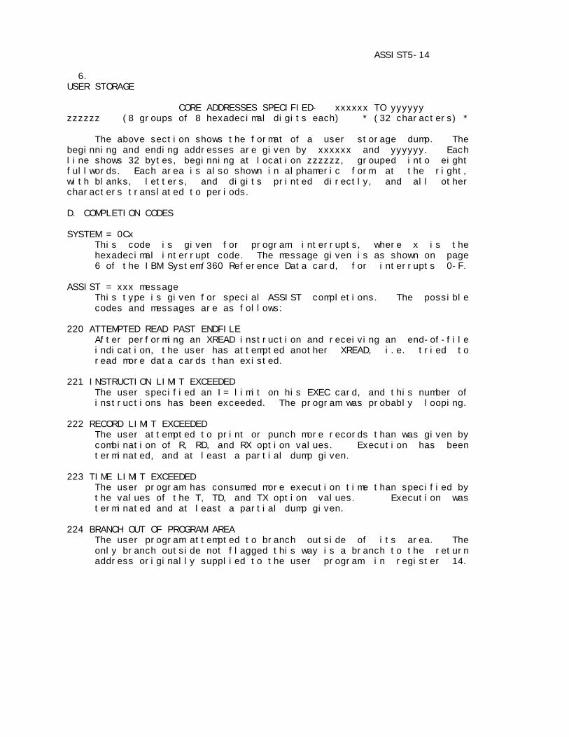
ASSIST5-14 6. USER STORAGE CORE ADDRESSES SPECIFIED- xxxxxx TO yyyyyy zzzzzz (8 groups of 8 hexadecimal digits each) * (32 characters) * The above section shows the format of a user storage dump. The beginning and ending addresses are given by xxxxxx and yyyyyy. Each line shows 32 bytes, beginning at location zzzzzz, grouped into eight fullwords. Each area is also shown in alphameric form at the right, with blanks, letters, and digits printed directly, and all other characters translated to periods. D. COMPLETION CODES SYSTEM = 0Cx This code is given for program interrupts, where x is the hexadecimal interrupt code. The message given is as shown on page 6 of the IBM System/360 Reference Data card, for interrupts 0-F. ASSIST = xxx message This type is given for special ASSIST completions. The possible codes and messages are as follows: 220 ATTEMPTED READ PAST ENDFILE After performing an XREAD instruction and receiving an end-of-file indication, the user has attempted another XREAD, i.e. tried to read more data cards than existed. 221 INSTRUCTION LIMIT EXCEEDED The user specified an I= limit on his EXEC card, and this number of instructions has been exceeded. The program was probably looping. 222 RECORD LIMIT EXCEEDED The user attempted to print or punch more records than was given by combination of R, RD, and RX option values. Execution has been terminated, and at least a partial dump given. 223 TIME LIMIT EXCEEDED The user program has consumed more execution time than specified by the values of the T, TD, and TX option values. Execution was terminated and at least a partial dump given. 224 BRANCH OUT OF PROGRAM AREA The user program attempted to branch outside of its area. The only branch outside not flagged this way is a branch to the return address originally supplied to the user program in register 14.
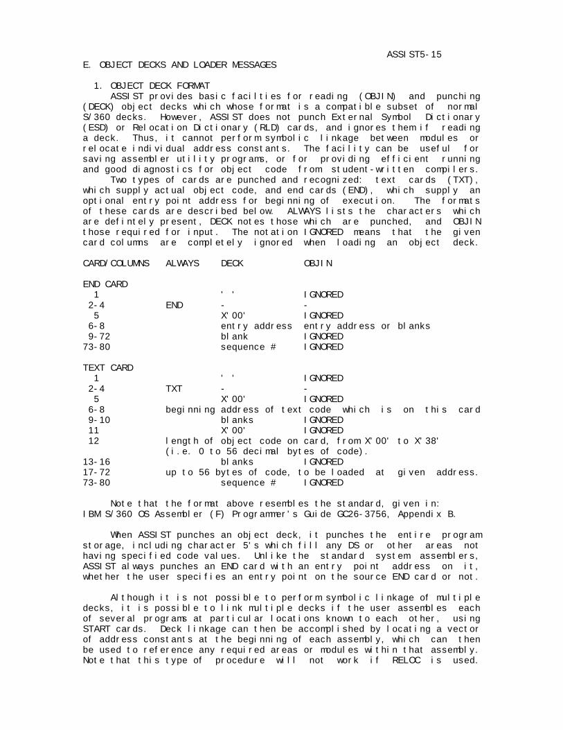
ASSIST5-15 E. OBJECT DECKS AND LOADER MESSAGES 1. OBJECT DECK FORMAT ASSIST provides basic facilties for reading (OBJIN) and punching (DECK) object decks which whose format is a compatible subset of normal S/360 decks. However, ASSIST does not punch External Symbol Dictionary (ESD) or Relocation Dictionary (RLD) cards, and ignores them if reading a deck. Thus, it cannot perform symbolic linkage between modules or relocate individual address constants. The facility can be useful for saving assembler utility programs, or for providing efficient running and good diagnostics for object code from student-written compilers. Two types of cards are punched and recognized: text cards (TXT), which supply actual object code, and end cards (END), which supply an optional entry point address for beginning of execution. The formats of these cards are described below. ALWAYS lists the characters which are defintely present, DECK notes those which are punched, and OBJIN those required for input. The notation IGNORED means that the given card columns are completely ignored when loading an object deck. CARD/COLUMNS ALWAYS DECK OBJIN END CARD 1 ' ' IGNORED 2-4 END - - 5 X'00' IGNORED 6-8 entry address entry address or blanks 9-72 blank IGNORED 73-80 sequence # IGNORED TEXT CARD 1 ' ' IGNORED 2-4 TXT - - 5 X'00' IGNORED 6-8 beginning address of text code which is on this card 9-10 blanks IGNORED 11 X'00' IGNORED 12 length of object code on card, from X'00' to X'38' (i.e. 0 to 56 decimal bytes of code). 13-16 blanks IGNORED 17-72 up to 56 bytes of code, to be loaded at given address. 73-80 sequence # IGNORED Note that the format above resembles the standard, given in: IBM S/360 OS Assembler (F) Programmer's Guide GC26-3756, Appendix B. When ASSIST punches an object deck, it punches the entire program storage, including character 5's which fill any DS or other areas not having specified code values. Unlike the standard system assemblers, ASSIST always punches an END card with an entry point address on it, whether the user specifies an entry point on the source END card or not. Although it is not possible to perform symbolic linkage of multiple decks, it is possible to link multiple decks if the user assembles each of several programs at particular locations known to each other, using START cards. Deck linkage can then be accomplished by locating a vector of address constants at the beginning of each assembly, which can then be used to reference any required areas or modules within that assembly. Note that this type of procedure will not work if RELOC is used.
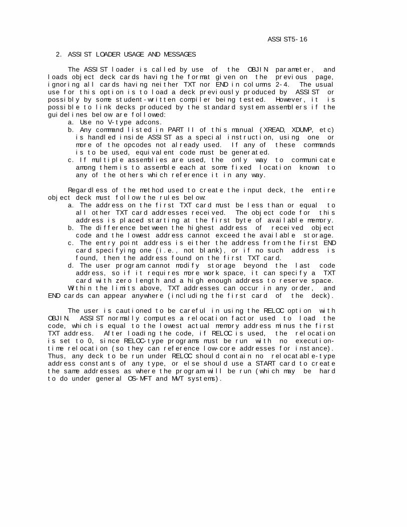
ASSIST5-16 2. ASSIST LOADER USAGE AND MESSAGES The ASSIST loader is called by use of the OBJIN parameter, and loads object deck cards having the format given on the previous page, ignoring all cards having neither TXT nor END in columns 2-4. The usual use for this option is to load a deck previously produced by ASSIST or possibly by some student-written compiler being tested. However, it is possible to link decks produced by the standard system assemblers if the guidelines below are followed: a. Use no V-type adcons. b. Any command listed in PART II of this manual (XREAD, XDUMP, etc) is handled inside ASSIST as a special instruction, using one or more of the opcodes not already used. If any of these commands is to be used, equivalent code must be generated. c. If multiple assemblies are used, the only way to communicate among them is to assemble each at some fixed location known to any of the others which reference it in any way. Regardless of the method used to create the input deck, the entire object deck must follow the rules below: a. The address on the first TXT card must be less than or equal to all other TXT card addresses received. The object code for this address is placed starting at the first byte of available memory. b. The difference between the highest address of received object code and the lowest address cannot exceed the available storage. c. The entry point address is either the address from the first END card specifying one (i.e., not blank), or if no such address is found, then the address found on the first TXT card. d. The user program cannot modify storage beyond the last code address, so if it requires more work space, it can specify a TXT card with zero length and a high enough address to reserve space. Within the limits above, TXT addresses can occur in any order, and END cards can appear anywhere (including the first card of the deck). The user is cautioned to be careful in using the RELOC option with OBJIN. ASSIST normally computes a relocation factor used to load the code, which is equal to the lowest actual memory address minus the first TXT address. After loading the code, if RELOC is used, the relocation is set to 0, since RELOC-type programs must be run with no execution- time relocation (so they can reference low-core addresses for instance). Thus, any deck to be run under RELOC should contain no relocatable-type address constants of any type, or else should use a START card to create the same addresses as where the program will be run (which may be hard to do under general OS-MFT and MVT systems).
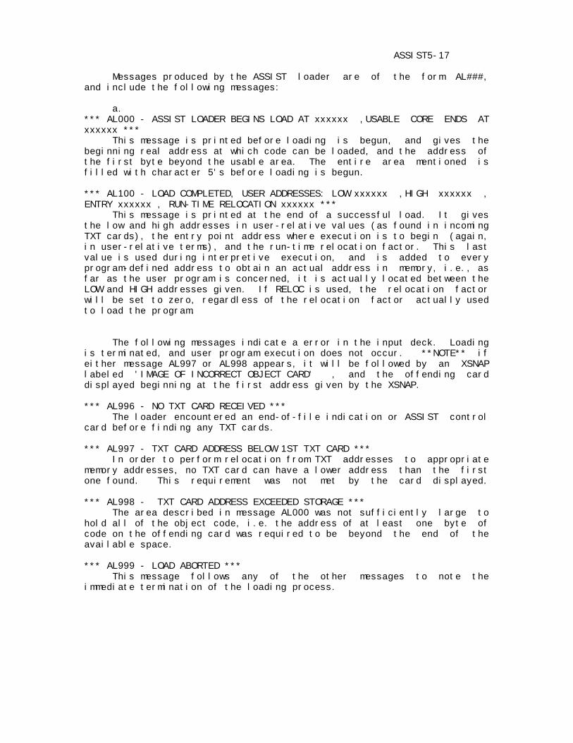
ASSIST5-17 Messages produced by the ASSIST loader are of the form AL###, and include the following messages: a. *** AL000 - ASSIST LOADER BEGINS LOAD AT xxxxxx ,USABLE CORE ENDS AT xxxxxx *** This message is printed before loading is begun, and gives the beginning real address at which code can be loaded, and the address of the first byte beyond the usable area. The entire area mentioned is filled with character 5's before loading is begun. *** AL100 - LOAD COMPLETED, USER ADDRESSES: LOW xxxxxx ,HIGH xxxxxx , ENTRY xxxxxx , RUN-TIME RELOCATION xxxxxx *** This message is printed at the end of a successful load. It gives the low and high addresses in user-relative values (as found in incoming TXT cards), the entry point address where execution is to begin (again, in user-relative terms), and the run-time relocation factor. This last value is used during interpretive execution, and is added to every program-defined address to obtain an actual address in memory, i.e., as far as the user program is concerned, it is actually located between the LOW and HIGH addresses given. If RELOC is used, the relocation factor will be set to zero, regardless of the relocation factor actually used to load the program. The following messages indicate a error in the input deck. Loading is terminated, and user program execution does not occur. **NOTE** if either message AL997 or AL998 appears, it will be followed by an XSNAP labeled 'IMAGE OF INCORRECT OBJECT CARD' , and the offending card displayed beginning at the first address given by the XSNAP. *** AL996 - NO TXT CARD RECEIVED *** The loader encountered an end-of-file indication or ASSIST control card before finding any TXT cards. *** AL997 - TXT CARD ADDRESS BELOW 1ST TXT CARD *** In order to perform relocation from TXT addresses to appropriate memory addresses, no TXT card can have a lower address than the first one found. This requirement was not met by the card displayed. *** AL998 - TXT CARD ADDRESS EXCEEDED STORAGE *** The area described in message AL000 was not sufficiently large to hold all of the object code, i.e. the address of at least one byte of code on the offending card was required to be beyond the end of the available space. *** AL999 - LOAD ABORTED *** This message follows any of the other messages to note the immediate termination of the loading process.

ASREPLGD-01 3.0/A June 1973 ASSIST ASSEMBLER REPLACEMENT USER'S GUIDE Program&Documentation: John R. Mashey Project Supervision : Graham Campbell PSU Computer Science Department PREFACE This manual is the key reference source for the programmer who uses the replacement facility of ASSIST. This facility allows the programmer to write and test his own versions of certain program modules which are part of the ASSIST Assembler. The modules which are replaceable perform a wide variety of functions, thus allowing for a number of different course assignments covering important segments of a running 360 Assembler. Among those replacable are modules for management of the symbol table, base register table, scanning and covnversion of various constant types, and evaluation of both self- defining terms and general expressions. The entire replacement process can be performed with low overhead, in-core, and batched, while allowing the user program no possible way to damage the rest of the ASSIST system. The first part of this manual briefly describes the internal structure of the ASSIST assembler, and lists the steps in the entire replacement process. Also included are the overall register and linkage conventions required of all replacable modules. The second section describes the additional debugging facilities available to the writer of a replacement module. The third section shows the deck setup, Job Control Language, and PARM options needed to make a replacement run. The fourth section lists all messages which may be printed by the ASSIST Replace Monitor during a replacement run. The reader should be familiar with the following manual: ASSIST INTRODUCTORY ASSEMBLER USER'S MANUAL The above manual gives various information which may be required to write a program which can be run under ASSIST, and explains the various messages which may generated (other than Replace Monitor messages). Note also that this manual is structured similar to the above one. For replacement of certain of the modules, it may be necessary to examine the following manual for additional required information: ASSIST SYSTEM PROGRAM LOGIC MANUAL

ASREPLGD-02 TABLE OF CONTENTS PART I. THE ASSIST REPLACEMENT PROCESS.............................. 03 A. OVERVIEW OF THE ASSIST ASSEMBLER................................. 03 B. STEPS IN THE REPLACEMENT PROCESS................................. 04 C. REGISTER AND SUBROUTINE LINKAGE CONVENTIONS...................... 06 PART II. REPLACE MONITOR DEBUGGING AIDS............................. 08 A. THE RFLAG........................................................ 08 B. THE XREPL INSTRUCTION............................................ 09 PART III. JOB CONTROL LANGUAGE AND PARM OPTIONS..................... 09 A. JOB CONTROL LANGUAGE FOR REPLACE RUN............................. 09 B. PARM OPTIONS..................................................... 09 PART IV. REPLACE MONITOR MESSAGES................................... 10
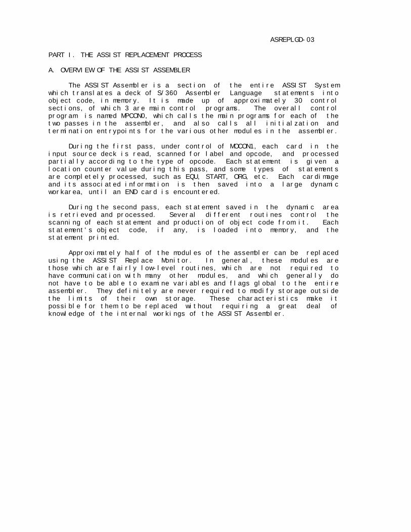
ASREPLGD-03 PART I. THE ASSIST REPLACEMENT PROCESS A. OVERVIEW OF THE ASSIST ASSEMBLER The ASSIST Assembler is a section of the entire ASSIST System which translates a deck of S/360 Assembler Language statements into object code, in memory. It is made up of approximately 30 control sections, of which 3 are main control programs. The overall control program is named MPCON0, which calls the main programs for each of the two passes in the assembler, and also calls all initialzation and termination entrypoints for the various other modules in the assembler. During the first pass, under control of MOCON1, each card in the input source deck is read, scanned for label and opcode, and processed partially according to the type of opcode. Each statement is given a location counter value during this pass, and some types of statements are completely processed, such as EQU, START, ORG, etc. Each cardimage and its associated information is then saved into a large dynamic workarea, until an END card is encountered. During the second pass, each statement saved in the dynamic area is retrieved and processed. Several different routines control the scanning of each statement and production of object code from it. Each statement's object code, if any, is loaded into memory, and the statement printed. Approximately half of the modules of the assembler can be replaced using the ASSIST Replace Monitor. In general, these modules are those which are fairly low-level routines, which are not required to have communication with many other modules, and which generally do not have to be able to examine variables and flags global to the entire assembler. They definitely are never required to modify storage outside the limits of their own storage. These characteristics make it possible for them to be replaced without requiring a great deal of knowledge of the internal workings of the ASSIST Assembler.
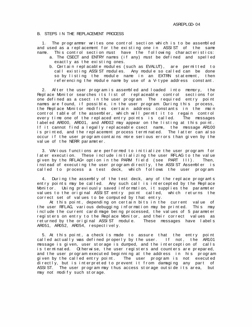
ASREPLGD-04 B. STEPS IN THE REPLACEMENT PROCESS 1. The programmer writes one control section which is to be assembled and used as a replacement for the existing one in ASSIST of the same name. This control section must have the following characteristics: a. The CSECT and ENTRY names (if any) must be defined and spelled exactly as the existing ones. b. Certain replacable modules (such as EVALUT), are permitted to call existing ASSIST modules. Any module so called can be done so by listing the module name in an EXTRN statement, then referencing the module name by use of a V-type address constant. 2. After the user program is assembled and loaded into memory, the Replace Monitor searches its list of replaceable control sections for one defined as a csect in the user program. The required entry point names are found, if possible, in the user program. During this process, the Replace Monitor modifies certain address constants in the main control table of the assembler, which will permit it to regain control every time one of the replaced entry points is called. The messages labeled AR000, AR001, and AR002 may appear on the listing at this point. If it cannot find a legally replaceable csect name, the message AR100 is printed, and the replacement process terminated. The latter can also occur if the user program contains more serious errors than given by the value of the NERR parameter. 3. VArious functions are performed to initialize the user program for later execution. These include initializing the user RFLAG to the value given by the RFLAG= option in the PARM field (see PART III). Then, instead of executing the user program directly, the ASSIST Assembler is called to process a test deck, which follows the user program. 4. During the assembly of the test deck, any of the replace program's entry points may be called. Any such call is intercepted by the Replace Monitor. Using previously saved information, it supplies the parameter values to the original ASSIST entry point called, which returns the correct set of values to be computed by that entry. At this point, depending on certain bits in the current value of the user RFLAG, various debugging information may be printed. This may include the current cardimage being processed, the values of 5 parameter registers on entry to the Replace Monitor, and their correct values as returned by the original ASSIST module. These messages have labels AR051, AR052, AR054, respectively. 5. At this point, a check is made to assure that the entry point called actually was defined properly by the user. If not, the AR101 message is given, user storage is dumped, and the interception of calls is terminated. Otherwise, the user registers and counters are prepared, and the user program executed beginning at the address in his program given by the called entry point. The user program is not executed directly, but is interpreted to prevent it from damaging any part of ASSIST. The user program may thus access storage outside its area, but may not modify such storage.
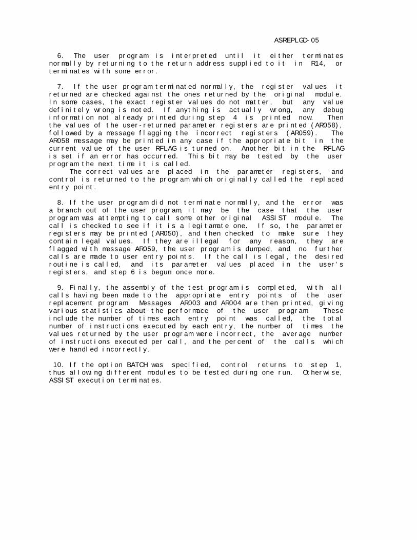
ASREPLGD-05 6. The user program is interpreted until it either terminates normally by returning to the return address supplied to it in R14, or terminates with some error. 7. If the user program terminated normally, the register values it returned are checked against the ones returned by the original module. In some cases, the exact register values do not matter, but any value definitely wrong is noted. If anything is actually wrong, any debug information not already printed during step 4 is printed now. Then the values of the user-returned parameter registers are printed (AR058), followed by a message flagging the incorrect registers (AR059). The AR058 message may be printed in any case if the appropriate bit in the current value of the user RFLAG is turned on. Another bit in the RFLAG is set if an error has occurred. This bit may be tested by the user program the next time it is called. The correct values are placed in the parameter registers, and control is returned to the program which originally called the replaced entry point. 8. If the user program did not terminate normally, and the error was a branch out of the user program, it may be the case that the user program was attempting to call some other original ASSIST module. The call is checked to see if it is a legitamate one. If so, the parameter registers may be printed (AR050), and then checked to make sure they contain legal values. If they are illegal for any reason, they are flagged with message AR059, the user program is dumped, and no further calls are made to user entry points. If the call is legal, the desired routine is called, and its parameter values placed in the user's registers, and step 6 is begun once more. 9. Finally, the assembly of the test program is completed, with all calls having been made to the appropriate entry points of the user replacement program. Messages AR003 and AR004 are then printed, giving various statistics about the performace of the user program. These include the number of times each entry point was called, the total number of instructions executed by each entry, the number of times the values returned by the user program were incorrect, the average number of instructions executed per call, and the percent of the calls which were handled incorrectly. 10. If the option BATCH was specified, control returns to step 1, thus allowing different modules to be tested during one run. Otherwise, ASSIST execution terminates.
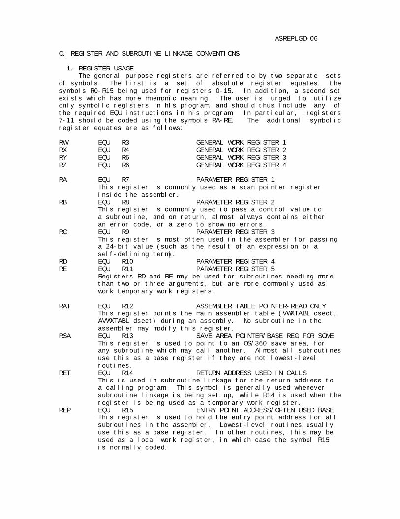
ASREPLGD-06 C. REGISTER AND SUBROUTINE LINKAGE CONVENTIONS 1. REGISTER USAGE The general purpose registers are referred to by two separate sets of symbols. The first is a set of absolute register equates, the symbols R0-R15 being used for registers 0-15. In addition, a second set exists which has more mnemonic meaning. The user is urged to utilize only symbolic registers in his program, and should thus include any of the required EQU instructions in his program. In particular, registers 7-11 should be coded using the symbols RA-RE. The additonal symbolic register equates are as follows: RW EQU R3 GENERAL WORK REGISTER 1 RX EQU R4 GENERAL WORK REGISTER 2 RY EQU R6 GENERAL WORK REGISTER 3 RZ EQU R6 GENERAL WORK REGISTER 4 RA EQU R7 PARAMETER REGISTER 1 This register is commonly used as a scan pointer register inside the assembler. RB EQU R8 PARAMETER REGISTER 2 This register is commonly used to pass a control value to a subroutine, and on return, almost always contains either an error code, or a zero to show no errors. RC EQU R9 PARAMETER REGISTER 3 This register is most often used in the assembler for passing a 24-bit value (such as the result of an expression or a self-defining term). RD EQU R10 PARAMETER REGISTER 4 RE EQU R11 PARAMETER REGISTER 5 Registers RD and RE may be used for subroutines needing more than two or three arguments, but are more commonly used as work temporary work registers. RAT EQU R12 ASSEMBLER TABLE POINTER-READ ONLY This register points the main assembler table (VWXTABL csect, AVWXTABL dsect) during an assembly. No subroutine in the assembler may modify this register. RSA EQU R13 SAVE AREA POINTER/BASE REG FOR SOME This register is used to point to an OS/360 save area, for any subroutine which may call another. Almost all subroutines use this as a base register if they are not lowest-level routines. RET EQU R14 RETURN ADDRESS USED IN CALLS This is used in subroutine linkage for the return address to a calling program. This symbol is generally used whenever subroutine linkage is being set up, while R14 is used when the register is being used as a temporary work register. REP EQU R15 ENTRY POINT ADDRESS/OFTEN USED BASE This register is used to hold the entry point address for all subroutines in the assembler. Lowest-level routines usually use this as a base register. In other routines, this may be used as a local work register, in which case the symbol R15 is normally coded.

ASREPLGD-07 2. LINKAGE CONVENTIONS - THE ASSEMBLER The linkage conventions inside the ASSIST assembler consist of a few modifications to the standard OS/360 linkage conventions, which have been changed mainly to save time and space. The differences are as follows: a. Registers R0-R6 (or R0-R2, RW-RZ) are protected across any calling sequence and must be restored if changed. R14 (RET) must also be restored if changed before returning. b.Register R12(RAT) may not be changed by any routine. c. Registers R7-R11 (RA-RE) are used for parameters and temporary work registers, and are not protected at all across calls. No routine ever requires more than five arguments, so these five registers are sufficient. d. Except for the above, all normal OS/360 conventions are followed regarding save area linkage requirements and usage. In general, most routine only save as many registers as required. Lowest-level routines use R15 as a base, and do not perfrom save area linkage, other routines usually use R13 as a base and save area pointer. e. For replacement runs, the user must include any needed EQU symbols for registers. Note that all documentation and output produced by the Replace Monitor refers to registers 7-11 as RA-RE, so that using these symbols in a replacement program will aid reading the various diagnostic output produced.

ASREPLGD-08 PART II. REPLACE MONITOR DEBUGGING AIDS A. THE RFLAG Communication between the user program and the Replace Monitor is achieved through the use of the User Replace Flag, called the RFLAG. This is a two-byte area of storage which may initialized for an entire run using the RFLAG= option in the PARM field. Certain bits in it determine which diagnostic messages the Replace Monitor prints when it intercepts a call to a replaced module. These bits can also be changed by the user program during execution, thus allowing the user to obtain additional information when needed. The various bits of the RFLAG are used as described in the table below. BYTE BITS DECIMAL BINARY MEANING IF BIT ON (AR### MESSAGE) ------------------------------------------------------------------------ 0 0-7 currently unused, user can set or test for his own purposes. 1 7 1 00000001 print current statement on entry (AR051) 6 2 00000010 print registers RA-RE on entry (AR052) 5 4 00000100 print correct regs RA-RE, on exit (AR054) from original ASSIST module 4 8 00001000 print registers RA-RE on exit from (AR058) user replacement module 3 16 00010000 print registers RA-RE if user (AR050) module calls an original ASSIST module. 1,2 64,32 01100000 reserved for future use 0 128 10000000 is set to 1 when there is an error (AR059) parameter registers returned by the user program. Is set to 0 if acceptable. ------------------------------------------------------------------------ Bit 0 of byte 1 can be used to start extra debugging output only after an error occurs. See the XREPL example for this action. The entire first byte is reserved for the user program, such as for additional debugging flag bits for controling the program. Note that bits 5,6,7 are tested before the call to the user program. Thus, changing them affects output beginning at the next call to a user module. B. THE XREPL INSTRUCTION The XREPL instruction is an SI format instruction, in which the immediate field is used to specify a type of action. It is coded as XREPL ADDR,CODE with CODE meaning as follows: 0 set the RFLAG from the 2-byte area specified by ADDR. 1 fetch the RFLAG into the 2-byte area specified by ADDR. 2 fetch the number of instructions left into the 4-byte area given by ADDR. This value is decremented each time an instruction is done. The following gives an example of the use of XREPL: XREPL MYRFLAG,1 get the value of the RFLAG TM MYRFLAG+1,128 was there an error last time BZ *+12 no, don't reset it OI MYRFLAG+1,8+4+2+1 set all these for debug output XREPL MYRFLAG,0 reset the RFLAG to new setting
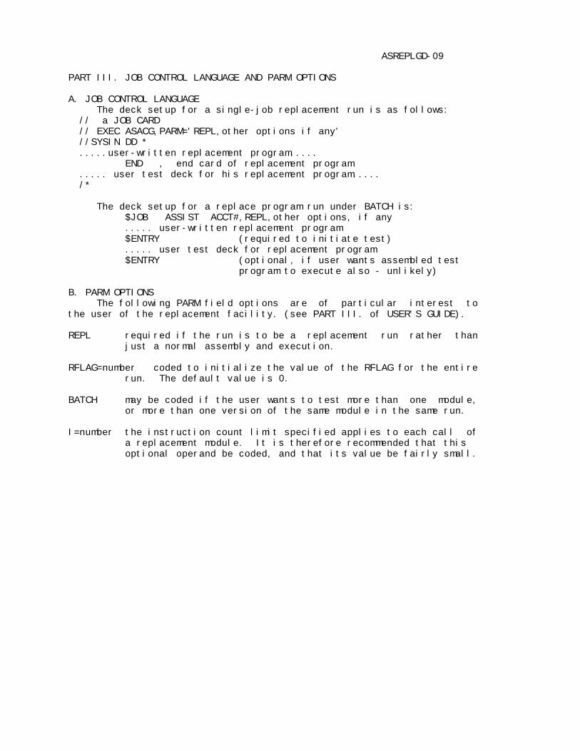
ASREPLGD-09 PART III. JOB CONTROL LANGUAGE AND PARM OPTIONS A. JOB CONTROL LANGUAGE The deck setup for a single-job replacement run is as follows: // a JOB CARD // EXEC ASACG,PARM='REPL,other options if any' //SYSIN DD * .....user-written replacement program..... END , end card of replacement program ..... user test deck for his replacement program..... /* The deck setup for a replace program run under BATCH is: $JOB ASSIST ACCT#,REPL,other options, if any ..... user-written replacement program $ENTRY (required to initiate test) ..... user test deck for replacement program $ENTRY (optional, if user wants assembled test program to execute also - unlikely) B. PARM OPTIONS The following PARM field options are of particular interest to the user of the replacement facility. (see PART III. of USER'S GUIDE). REPL required if the run is to be a replacement run rather than just a normal assembly and execution. RFLAG=number coded to initialize the value of the RFLAG for the entire run. The default value is 0. BATCH may be coded if the user wants to test more than one module, or more than one version of the same module in the same run. I=number the instruction count limit specified applies to each call of a replacement module. It is therefore recommended that this optional operand be coded, and that its value be fairly small.
ASREPLGD-10 PART IV. REPLACE MONITOR MESSAGES The following lists the messages which may be produced during a replace run by the Replace Monitor. Note that all these messages are printed inline with output produced by other sections of ASSIST. In particular, Replace Monitor output is embedded in the listing of the user test program, which can possibly make it difficult to read in some cases. A helpful procedure is to run the test program by itself under ASSIST, thus obtaining a listing, then insert a PRINT OFF command at the beginning. This will remove most of he test program listing. All Replace Monitor messages are of the form ///AR### message. The type of message is indicated by the value of ###, as follows: 000-049 - informative or warning messages. 050-099 - debugging output messages,produced during intercepted call. 100-199 - severe error message, causing replacement interception to end. AR000 REPLACE CSECT: name /// This message appears immediately after the replace csect has been assembled, with name being the name of the replacing csect. AR001 REPLACE ENTRY: name AT LOCATION: xxxxxx /// If message AR000 appears, each properly defined entry point in the csect will be listed here with its location xxxxxx in memory. Note that a csect which can be entered through its csect name is also listed. AR002 REPLACE ENTRY: name NOT FOUND AS CSECT OR ENTRY /// This message may appear with the AR000 and AR001 messages for any entry or csect name which is required, but either not defined in the user program or not declared as CSECT or ENTRY. If this entry name is called during execution, its execution will be terminated with an AR101 message and storage dump. AR003 STATISTICS: # INSTRUCTIONS # CALLS # WRONG INSTRS/CALL %WRONG This message appears after the test program is assembled. AR004 name : 5 decimal numbers One of this message appears for each entry point after AR003. It describes the performance of the named entry point during the run. AR050 ON CALL TO name REGISTERS RA-RE (values of regs 7-11) This message may be printed if the RFLAG byte 1 bit 3 is set and the user program calls some other ASSIST module. It may also be printed if the user program tries to pass illegal parameter values to the routine name.

ASREPLGD-11 AR051 ON ENTRY TO name STMT ADDR: xxxxxx -> cardimage This message is printed before calling the user program, and shows the current statement being processed, if any. The address of the cardimage is given by xxxxxx, which corresponds to the first character following the '>' in the message. The message is if RFLAG byte 1 bit 7 is set before the call, or if an error occurs in the user program. AR052 ON ENTRY TO name REGISTERS RA-RE: (values of 5 registers) This message displays the 5 parameter registers before the user program name is called, and is printed if RFLAG byte 1 bit 6 is on before the user program is called, or if there is an error. AR054 ON EXIT FROM name REGISTERS RA-RE: (values of 5 registers) This message shows the correct values of the parameter registers as returned by the original ASSIST module name. It is printed if RFLAG byte 1 bit 5 is on before call to the module, or if the user program makes an error. AR058 ON EXIT FROM name REGISTERS RA-RE: (values of 5 registers) If RFLAG byte 1 bit 4 is on after completion of the user program, or if there is an error, this message appears, and gives the values of the parameter registers as returned by the user entry name. AR059 WARNING: ERROR IN USER REGS: error list If any of the user registers has an incorrect value, this message is printed, either following AR050 or AR058, depending on whether the incorrect value(s) were in a call to another module or in a return of values to the calling program. The error list consists of one or more of the following: R0-R6 when a user program returned, the values in registers 0-6 were not all the same as when it was called. R12 the user program modified the value of the assembler table pointer, which is not permitted. R13 the user did not restore the save area pointer. $$$$$$$$ The dollar signs indicate a register shown in messages AR050 or AR058 as incorrect. If this message appears, RFLAG byte 1 bit 0 is set to 1 for the next time the user program is called. AR100 REPLACE CSECT NOT FOUND - REPLACE ABORT /// This message appears immediately after the assembly of the user program. None of the allowable csect names were found as a csect in the user program. AR101 INVALID ENTRYPOINT NAME: name CALLED. REPLACE ACTION ABORTED /// If name appeared in an AR002 message and is called, this message appears, followed by a dump of user storage and the last values of the user registers. AR102 USER PROGRAM ABENDED DURING REPLACEMENT /// Replace action is aborted and a dump given.