Embed Size (px)
Citation preview

Assignment No. 1
Title: Write an ALP to count no. of positive and negative numbers from the array.
Environment:
OS: ubuntu 12.10
Assembler: NASM
Linker: ld
Theory:
Introduction to Assembly Language Programming:
Each personal computer has a microprocessor that manages the computer's arithmetical, logical and control activities.
Each family of processors has its own set of instructions for handling various operations like getting input from keyboard, displaying information on screen and performing various other jobs. These set of instructions are called 'machine language instruction'.
Processor understands only machine language instructions which are strings of 1s and 0s. However machine language is too obscure and complex for using in software development. So the low level assembly language is designed for a specific family of processors that represents various instructions in symbolic code and a more understandable form.
Assembly language is a low-level programming language for a computer, or other programmable device specific to particular computer architecture in contrast to most high-level programming languages, which are generally portable across multiple systems. Assembly language is converted into executable machine code by a utility program referred to as an assembler like NASM, MASM etc.
Advantages of Assembly Language
An understanding of assembly language provides knowledge of: Interface of programs with OS, processor and BIOS; Representation of data in memory and other external devices; How processor accesses and executes instruction; How instructions accesses and process data; How a program access external devices.
Other advantages of using assembly language are:
It requires less memory and execution time; It allows hardware-specific complex jobs in an easier way; It is suitable for time-critical jobs;
ALP Step By Step:
Installing NASM:
If you select "Development Tools" while installed Linux, you may NASM installed along with the Linux operating system and you do not need to download and install it separately. For checking whether you already have NASM installed, take the following steps:
Open a Linux terminal. Type whereis nasm and press ENTER. If it is already installed then a line like, nasm: /usr/bin/nasm appears. Otherwise, you will see
justnasm:, then you need to install NASM.
To install NASM take the following steps:
Check The netwide assembler (NASM) website for the latest version. Download the Linux source archive nasm-X.XX. ta .gz, where X.XX is the NASM version
number in the archive. Unpack the archive into a directory, which creates a subdirectory nasm-X. XX. cd to nasm-X. XX and type ./configure . This shell script will find the best C compiler to use and
set up Makefiles accordingly. Type make to build the nasm and ndisasm binaries. Type make install to install nasm and ndisasm in /usr/local/bin and to install the man pages.
This should install NASM on your system. Alternatively, you can use an RPM distribution for the Fedora Linux. This version is simpler to install, just double-click the RPM file.
Assembly Basic Syntax:
An assembly program can be divided into three sections:
The data section The bss section The text section
The order in which these sections fall in your program really isn’t important, but by convention the .data section comes first, followed by the .bss section, and then the .text section.
The .data Section
The .data section contains data definitions of initialized data items. Initialized data is data that has a value before the program begins running. These values are part of the executable file. They are loaded into memory when the executable file is loaded into memory for execution. You don’t have to load them with their values, and no machine cycles are used in their creation beyond what it takes to load the program as a whole into memory.
The important thing to remember about the .data section is that the more initialized data items you define, the larger the executable file will be, and the longer it will take to load it from disk into memory when you run it.
section .data
The .bss Section
Not all data items need to have values before the program begins running. When you’re reading data from a disk file, for example, you need to have a place for the data to go after it comes in from disk. Data buffers like that are defined in the .bss section of your program. You set aside some number of bytes for a buffer and give the buffer a name, but you don’t say what values are to be present in the buffer.
There’s a crucial difference between data items defined in the .data section and data items defined in the .bss section: data items in the .data section add to the size of your executable file. Data items in the .bss section do not.
section .bss
The .text Section
The actual machine instructions that make up your program go into the .text section. Ordinarily, no data items are defined in .text. The .text section contains symbols called labels that identify locations in the program code for jumps and calls, but beyond your instruction mnemonics, that’s about it.
All global labels must be declared in the .text section, or the labels cannot be ‘‘seen’’ outside your program by the Linux linker or the Linux loader. Let’s look at the labels issue a little more closely.
section .text
Labels
A label is a sort of bookmark, describing a place in the program code and giving it a name that’s easier to remember than a naked memory address.
Labels are used to indicate the places where jump instructions should jump to, and they give names to callable assembly language procedures.

Here are the most important things to know about labels:
Labels must begin with a letter, or else with an underscore, period, or question mark. These last three have special meanings to the assembler, so don’t use them until you know how NASM interprets them.
Labels must be followed by a colon when they are defined. This is basically what tells NASM that the identifier being defined is a label. NASM will punt if no colon is there and will not flag an error, but the colon nails it, and prevents a mistyped instruction mnemonic from being mistaken for a label. Use the colon!
Labels are case sensitive. So yikes:, Yikes:, and YIKES: are three completely different labels. This differs from practice in a lot of other languages (Pascal particularly), so keep it in mind.
Assembly Language Statements
Assembly language programs consist of three types of statements:
Executable instructions or instructions Assembler directives or pseudo-ops Macros
Syntax of Assembly Language Statements
[label] mnemonic [operands] [;comment]
Positive and Negative Number:---
In computing, signed number representations are required to encode negative numbers in binary number systems.
The early days of digital computing were marked by a lot of competing ideas about both hardware technology and mathematics technology (numbering systems). One of the great debates was the format of negative numbers, with some of the era's most expert people having very strong and different opinions. One camp supported two's complement, the system that is dominant today. Another camp supported ones' complement, where any positive value is made into its negative equivalent by inverting all of the bits in a word. A third group supported "sign & magnitude" (sign-magnitude), where a value is changed from positive to negative simply by toggling the word's sign (high-order) bit.
In mathematics, negative numbers in any base are represented by prefixing them with a − sign. However, in computer hardware, numbers are represented in bit vectors only, without extra symbols. The four best-known methods of extending the binary numeral system to represent signed numbers are: sign-and-magnitude, ones' complement, two's complement, and excess-K. Some of the alternative methods use implicit instead of explicit signs, such as negative binary, using the base −2. Corresponding methods can be devised for other bases, whether positive, negative, fractional, or other elaborations on such themes. There is no definitive criterion by which any of the representations is universally superior. The representation used in most current computing devices is two's complement
Mathematical Model
S= {s,e,a,b, Fme, FF,MEM shared}
1. S : S is distinct start of program
S -> Global _start
_start:
1. e: e is distinct end of program
mov eax,1
mov ebx ,0
int 80h
2. a: It is input of program
a= {array of numbers_block }
3. b: It is an output of program
b= {count of No_of_positive and No_of_Negative}
4. Fme:This is friend function used in program. We have the following functions in friend function
I. Numascii II. Convert
1. FF: The system extern invalid state if
-wrong no entered from user
-register contents which differ after calling procedure
-invalid operand specifications
-invalid addressing modes
2. MEM shared: This is memory shared in the program. We have used the shared memory in
the following.
I. Accept Procedure
II. Display Procedure
III. Display Block Procedure
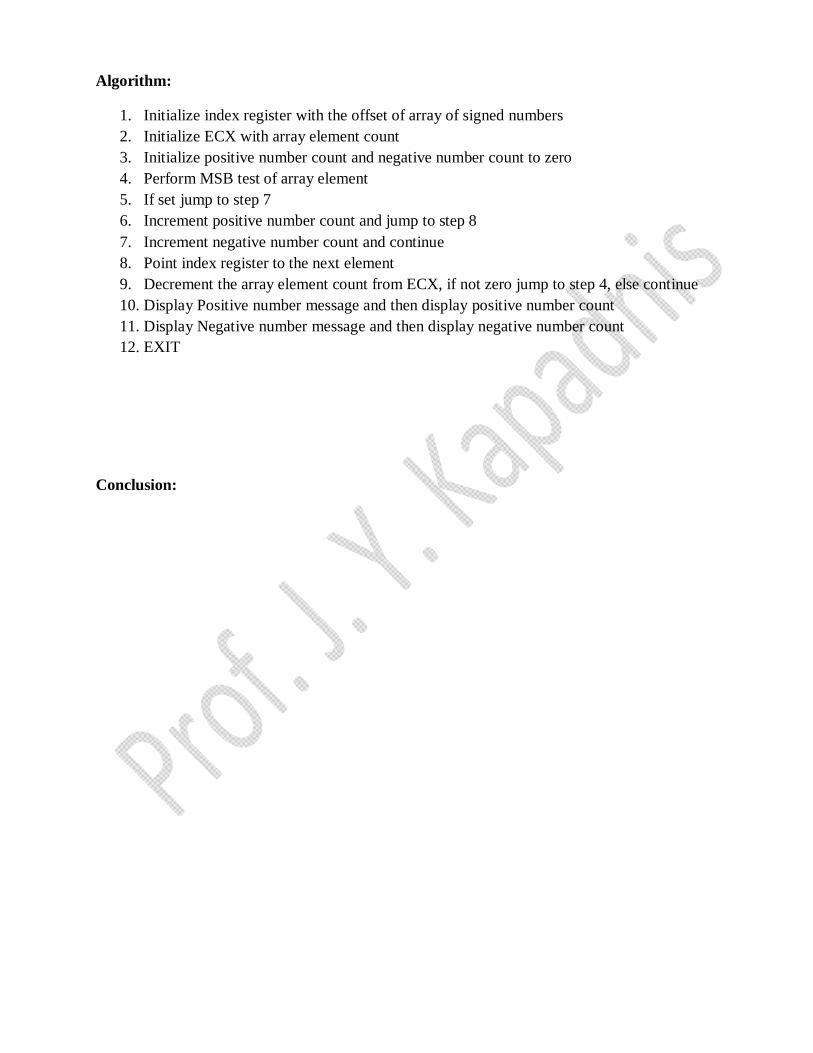
Algorithm:
1. Initialize index register with the offset of array of signed numbers 2. Initialize ECX with array element count 3. Initialize positive number count and negative number count to zero 4. Perform MSB test of array element 5. If set jump to step 7 6. Increment positive number count and jump to step 8 7. Increment negative number count and continue 8. Point index register to the next element 9. Decrement the array element count from ECX, if not zero jump to step 4, else continue 10. Display Positive number message and then display positive number count 11. Display Negative number message and then display negative number count 12. EXIT
Conclusion:

Assignment 2(A):
Problem Definition:
Write X86/64 ALP to perform non-overlapped transfer (with and without string specific instructions).
Block containing data can be defined in the data segment.
Explanation:
Consider that a block of data of N bytes is present at source location. Now this block of N bytes
is to be moved from source location to a destination location.
Let the number of bytes N = 05.
We will have to initialize this as count.
We know that source address is in the ESI register and destination address is in the EDI register.
For block transfer without string instruction, move contents at ESI to accumulator and from
accumulator to memory location of EDI and increment ESI and EDI for next content transfer.
For block transfer with string instruction, clear the direction flag. Move the data from source
location to the destination location using string instruction.
Mathematical Model
S= {s,e,a,b, Fme, FF,MEM shared}
1. S : S is distinct start of program
S -> Global _start
_start:
2. e: e is distinct end of program
mov eax,1
movebx ,0
int 80h
3. a: It is input of program
a= {source block, srcblock, choice}
4. b: It is an output of program
b= {destination block, destblock, contents}
5. Fme:This is friend function used in program. We have the following functions in friend function
III. Numascii IV. Convert

3. FF: The system extern invalid state if
-wrong position for overlapping
-register contents which differ after calling procedure
-invalid operand specifications
-invalid addressing modes
4. MEM shared: This is memory shared in the program. We have used the shared memory in
the following.
IV. Accept Procedure
V. Display Procedure
VI. Display Block Procedure
Instructions needed:
1. MOVSB-This is a string instruction and it moves string bytefrom source to destination.
2. REP- This is prefix that are applied to string operation. Each prefix cause the string instruction
that follows to be repeated the number of times indicated in the count register.
3. CLD-Clear Direction flag. ESI and EDI will be incremented and DF = 0
4. STD- Set Direction flag. ESI and EDI will be incremented and DF = 1
5. ROL-Rotates bits of byte or word left.
6. AND-AND each bit in a byte or word with corresponding bit in another byte or word.
7. INC-Increments specified byte/word by1.
8. DEC-Decrements specified byte/word by1.
9. JNZ-Jumps if not equal to Zero.
10. JNC-Jumps if no carry is generated.
11. CMP-Compares to specified bytes or words.
12. JBE-Jumps if below or equal.
13. ADD-Adds specified byte to byte or word to word.
14. CALL-Transfers the control from calling program to procedure.
15. RET-Return from where call is made.
Algorithm:
1. Start
2. Initialize data section.
3. Initialize the count, source block and destination block.

4. Using Macro display the Menu for block transfer without string instruction, block transfer with
string instruction and exit.
5. If choice = 1, call procedure for block transfer without string instruction.
6. If choice = 2, call procedure for block transfer with string instruction.
7. If choice = 3, terminate the program.
Algorithm for procedure for non overlapped block transfer without string instruction:
1. Initialize ESI and EDI with source and destination address.
2. Move count in ECX register.
3. Move contents at ESI to accumulator and from accumulator to memory location of EDI.
4. Increment ESI and EDI to transfer next content.
5. Repeat procedure till count becomes zero.
Algorithm for procedure for non overlapped block transfer with string instruction:
1. Initialize ESI and EDI with source and destination address.
2. Move count in ECX register.
3. Clear the direction flag.
4. Move the contents from source location to the destination location using string instruction.
5. Repeat string instruction the number of times indicated in the count register.
Conclusion:

Assignment 2(B)
Problem Definition:
Write X86/64 ALP to perform overlapped block transfer (with and without string specific instructions).
Block containing data can be defined in the data segment.
Explanation:
Consider that a block of data of N bytes is present at source location. Now this block of N bytes
is to be moved from source location to a destination location.
Let the number of bytes N = 05.
We will have to initialize this as count.
Overlap the source block and destination block.
We know that source address is in the ESI register and destination address is in the EDI register.
For block transfer without string instruction, move contents at ESI to accumulator and from
accumulator to memory location of EDI and decrement ESI and EDI for next content transfer.
For block transfer with string instruction, set the direction flag. Move the data from source
location to the destination location using string instruction.
Mathematical Model
S= {s,e,a,b, Fme, FF,MEM shared}
1. S : S is distinct start of program
S -> Global _start
_start:
5. e: e is distinct end of program
mov eax,1
movebx ,0
int 80h
6. a: It is input of program
a= {source block, srcblock,choice}
7. b: It is an output of program
b= {destination block, destblock, contents}
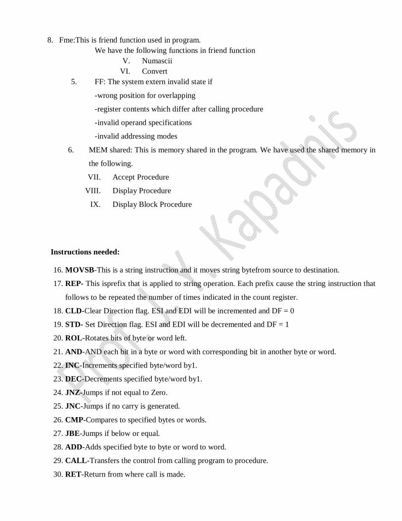
8. Fme:This is friend function used in program. We have the following functions in friend function
V. Numascii VI. Convert
5. FF: The system extern invalid state if
-wrong position for overlapping
-register contents which differ after calling procedure
-invalid operand specifications
-invalid addressing modes
6. MEM shared: This is memory shared in the program. We have used the shared memory in
the following.
VII. Accept Procedure
VIII. Display Procedure
IX. Display Block Procedure
Instructions needed:
16. MOVSB-This is a string instruction and it moves string bytefrom source to destination.
17. REP- This isprefix that is applied to string operation. Each prefix cause the string instruction that
follows to be repeated the number of times indicated in the count register.
18. CLD-Clear Direction flag. ESI and EDI will be incremented and DF = 0
19. STD- Set Direction flag. ESI and EDI will be decremented and DF = 1
20. ROL-Rotates bits of byte or word left.
21. AND-AND each bit in a byte or word with corresponding bit in another byte or word.
22. INC-Increments specified byte/word by1.
23. DEC-Decrements specified byte/word by1.
24. JNZ-Jumps if not equal to Zero.
25. JNC-Jumps if no carry is generated.
26. CMP-Compares to specified bytes or words.
27. JBE-Jumps if below or equal.
28. ADD-Adds specified byte to byte or word to word.
29. CALL-Transfers the control from calling program to procedure.
30. RET-Return from where call is made.
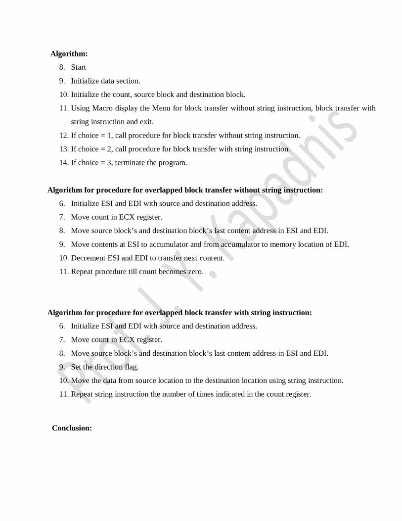
Algorithm:
8. Start
9. Initialize data section.
10. Initialize the count, source block and destination block.
11. Using Macro display the Menu for block transfer without string instruction, block transfer with
string instruction and exit.
12. If choice = 1, call procedure for block transfer without string instruction.
13. If choice = 2, call procedure for block transfer with string instruction.
14. If choice = 3, terminate the program.
Algorithm for procedure for overlapped block transfer without string instruction:
6. Initialize ESI and EDI with source and destination address.
7. Move count in ECX register.
8. Move source block’s and destination block’s last content address in ESI and EDI.
9. Move contents at ESI to accumulator and from accumulator to memory location of EDI.
10. Decrement ESI and EDI to transfer next content.
11. Repeat procedure till count becomes zero.
Algorithm for procedure for overlapped block transfer with string instruction:
6. Initialize ESI and EDI with source and destination address.
7. Move count in ECX register.
8. Move source block’s and destination block’s last content address in ESI and EDI.
9. Set the direction flag.
10. Move the data from source location to the destination location using string instruction.
11. Repeat string instruction the number of times indicated in the count register.
Conclusion:

Assignment 3:
Problem Definition:
Write 64 bit ALP to convert 4-digit Hex number into its equivalent BCD number and 5-digitBCD
number into its equivalent HEX number. Make your program user friendly to acceptthe choice from
user for :
(a) HEX to BCD (b) BCD to HEX (c) EXIT.
Display proper strings to prompt the user while accepting the input and displaying theresult.
Explanation:
HEX to BCD
Divide FFFF by 10 this FFFF is as decimal 65535 so Division 65535 / 10 Quotient = 6553 Reminder = 5 6553 / 10 Quotient = 655 Reminder = 3 655 / 10 Quotient = 65 Reminder = 5 65 / 10 Quotient = 6 Reminder = 5 6 / 10 Quotient = 0 Reminder = 6
and we are pushing Reminder on stack and then printing it in reverse order
BCD to HEX
1 LOOP : DL = 06 ; RAX = RAX * RBX = 0 ; RAX = RAX + RDX = 06 2 LOOP : DL = 05 ; 60 = 06 * 10 ; 65 = 60 + 5 3 LOOP : DL = 05 ; 650 = 60 * 10 ; 655 = 650 + 5 4 LOOP : DL = 03 ; 6550 = 655 * 10 ; 6553 = 6550 + 3 5 LOOP : DL = 06 ; 65530 = 6553 * 10 ; 65535 = 65530 + 5 Hence final result is in RAX = 65535 which is 1111 1111 1111 1111 and when we print this it is represented as FFFF.
Mathematical Modeling
S= {s,e,a,b, Fme, FF,MEM shared}
1. S : S is distinct start of program
S -> Global _start
_start:
2. e: e is distinct end of program

mov eax,1
movebx ,0
int 80h
3. a: It is input of program
a-> 1) Choice
2) Hex number
3) BCD number
4) Digit count
4. b: It is an output of program
b-> 1) Equivalent BCD number
2) Equivalent Hex number
5. Fme: This is friend function used in program.
We have the following functions in friend function
I. hex2bcd_proc
II. bcd2hex_proc
6. FF: The system enters invalid state if
-wrong BCD numbers are entered.
-wrong Hexnumbers are entered.
-invalid operand specifications
7. MEM shared: This is memory shared in the program. We have used the shared
memory in the following.
I. Accept Procedure
II. Display Procedure
Algorithm:
1. Start
2. Initialize data section.
3. Using Macro display the Menu for HEX to BCD, BCD to HEX and exit. Accept the choice
from user.
4. If choice = 1, call procedure for HEX to BCD conversion.
5. If choice = 2, call procedure for BCD to HEX conversion.
6. If choice = 3, terminate the program.
Algorithm for procedure for HEX to BCD conversion:
7. Accept 4-digit hex number from user.
8. Make count in RCX register 0.
9. Move accepted hex number in BX to AX.
10. Move base of Decimal numberthat is 10 in BX.
11. Move zero in DX.
12. Divide accepted hex number by 10. Remainder will return in DX.
13. Push remainder in DX on to stack.
14. Increment RCX counter.
15. Check whether AX contents are zero.
16. If it is not zero then go to step 5.
17. If AX contents are zero then pop remainders in stack in RDX.
18. Add 30 to get the BCD number.
19. Increment RDI for next digit and go to step 11.
Algorithm for procedure for BCD to HEX:
1. Accept 5-digit BCD number from user.
2. Take count RCX equal to 05.
3. Move 0A that is 10 in EBX.
4. Move zero in RDX register.
5. Multiply EBX with contents in EAX.
6. Move contents at RSI that is number accepted from user to DL.
7. Subtract 30 from DL.
8. Add contents of RDX to RAX and result will be in RAX.
9. Increment RSI for next digit and go to step 4 and repeat till RCX becomes zero.
10. Move result in EAX to EBX and call display procedure.
Conclusion:

Assignment 4(A):
Problem Definition:
Write X86/64 ALP to perform multiplication of two 8-bit hexadecimal numbers. Usesuccessive
addition method. Accept input from the user.
Successive Addition Method:
Assuming that MUL instruction is not available in the instruction set of 8086,writea program in
assembly language of 8086 to simulate the MUL instruction. Assuming that two digits are available in
EAX and BL registers. Use successive addition method.
Explanation:
Consider that a byte is present in the EAX register and second byte is present in theBL register.
We have to multiply the byte in EAX with the byte in BL.
We will multiply the numbers using successive addition method.
In successive addition method, one number is accepted and other number is taken asa counter.
The first number is added with itself, till the counter decrements to zero.
Result is stored in EBX register. Display the result, using display routine.
For example : AL = 12 H, BL = 10 H
Result = 12H + 12H + 12H + 12H + 12H + 12H + 12H + 12H + 12H + 12H
Result = 0120 H
Mathematical Modelling
S= {s,e,a,b, Fme, FF,MEM shared}
1. S : S is distinct start of program
S -> Global _start
_start:
2. e: e is distinct end of program
mov eax,1
movebx ,0
int 80h
3. a: It is input of program
a-> 1) First number for multiplication
2) Second number for multiplication
4. b: It is an output of program
b-> 1) Multiplication of two numbers by successive addition method
2)Multiplication of two numbers by add and shift method
5. Fme: This is friend function used in program.
We have the following functions in friend function
I. Numascii
II. Convert
6. FF: The system enters invalid state if
-numbers are not entered properly.
-numbers entered by user are larger than buffer size.
7. MEM shared: This is memory shared in the program. We have used the shared
memory in the following.
I. Accept Procedure
II. Display Procedure
Algorithm:
1. Start
2. Initialize data section.
3. Get the first number.
4. Get the second number as counter.
5. Initialize result = 0.
6. Result = Result + First number.
7. Decrement counter
8. If count is not equal to 0, go to step V.
9. Display the result.
10. Stop.
Conclusion:
Assignment 4 (B):
Problem Definition:
Write X86/64 ALP to perform multiplication of two 8-bit hexadecimal numbers. Use add and shift
method. Accept input from the user.
Successive Addition Method :
Assuming that MUL instruction is not available in the instruction set of 8086, writea program in
assembly language of 8086 to simulate the MUL instruction.Assuming that two digits are available in
AL and BL registers. Use successiveaddition method.
Explanation :
Consider that one byte is present in the AL register and another byte is present in
the BL register.
We have to multiply the byte in AL with the byte in BL.
We will multiply the numbers using add and shift method. In this method we rotate first number
right through carry and we check the carry. If carry is generated shift left second number by
count in CL register and add the shifted number to result.
Mathematical Modeling
S= {s,e,a,b, Fme, FF,MEM shared}
1. S : S is distinct start of program
S -> Global _start
_start:
2. e: e is distinct end of program
mov eax,1
movebx ,0
int 80h
3. a: It is input of program
a-> 1) First number for multiplication
2) Second number for multiplication
4. b: It is an output of program
b-> 1) Multiplication of two numbers by successive addition method
2)Multiplication of two numbers by add and shift method
5. Fme: This is friend function used in program.
We have the following functions in friend function
III. Numascii
IV. Convert
6. FF: The system enters invalid state if
-numbers are not entered properly.
-numbers entered by user are larger than buffer size.
7. MEM shared: This is memory shared in the program. We have used the shared
memory in the following.
III. Accept Procedure
IV. Display Procedure
Algorithm:
1. Start
2. Initialize data section.
20. Get the first number.
21. Get the second number.
22. Initialize result = 0.
23. Initialize the CL counter to 0 and edx to 08 (as 8bit numbers).
24. Rotate right through carry first number in AL by 1 bit.
25. If carry is generated (carry=1) then go to next step(9) and if carry is not generated go to step 12.
26. Make contents of BH=00.
27. Shift left second number in BX by CL count register.
28. Add contents of BX to the results.
29. Increment CLand decrement EDX.
30. Display the result using display procedure.
31. Stop.
Conclusion:
Assignment No.5
Aim: Write X86 ALP to find, a) Number of Blank spaces b) Number of lines c) Occurrence of a
particular character. Accept the data from the text file. The text file has to be accessed during
Program_1 execution and write FAR PROCEDURES in Program_2 for the rest of the
processing. Use of PUBLIC and EXTERN directives is mandatory.
Software/Hardware Required:
Core 2 duo/i3/i5/i7 - 64bit processor
Operating System – ubuntu/Fedora 64bit OS
Assembler: NASM
Editor Used – gedit
Theory:
Near Procedure:
Far Procedure
Explanation:
Open given text file. Read the content of file and store it in a buffer. Call far procedure which
will calculate the number of blank spaces, lines and occurrence of a particular character from the
buffer.
Assembler Directives Used: (Explain it by your own)
• Extern:
• Global:
Instructions: (Explain instruction used by your own)
Mathematical Model (Draw it by you own)
Flowchart (Draw it by your own)
Input: Text File
Output: Display of-
1. Number of Blank spaces
2. Number of lines
3. Occurrence of a particular character.
Main Algorithm:
A1: Algorithm for program_1
i. Start
ii. Initialize all the sections needed in programming
iii. Display “Enter file name” message using Print macro expansion
iv. Accept file name using Accept macro and store in filename buffer
v. Display “Enter character to search” message with the expansion of
Print macro
vi. Read character using Accept macro expansion
vii. Open file using fopen macro
viii. Compare RAX with -1H if equal then display error message “Error in
Opening File” with Print macro expansion else go to step ix
ix. Read content of opened file in buffer
x. Store file length in abuf_len
xi. Call far_procedure
xii. Stop
Macros:
Macro 1
1. Name : Print
2. Purpose: to display the messages by replacing the whole code by simple macro
declaration
3. I/P: sys_write call Number i.e rax=1, File descriptor (for Standard output rdi=1), Buffer
Address in rsi, and length of Buffer in rdx. Then Call syscall.
Macro 2
1. Name : Accept
2. Purpose: to accept input from the user by replacing the whole code by simple macro
declaration
4. I/P: sys_read call Number i.e rax=0, File descriptor (for Standard input rdi=0), Buffer
Address in rsi, and length of Buffer in rdx. Then Call syscall.
Macro 3
1. Name : fopen
2. Purpose: to open a file in given mode
3. I/P: sys_write call Number i.e rax=2, File name in rdi, Mode of file in rsi
(R=0,W=1,RW=2), and file permission in rdx. Then Call syscall.
Macro 4
1. Name : fread

2. Purpose: to read the content of file
3. I/P: sys_read call Number i.e rax=0, File descriptor in rdi , Buffer Address in rsi, and
length of Buffer in rdx. Then Call syscall.
Macro 5
3. Name : fclose
4. Purpose: to close opened file
5. I/P: sys_read call Number i.e rax=3, File handler in rdi. Then Call syscall.
Procedure: 1
1. Name : far_procedure
2. Purpose: to count 1. Number of Blank spaces 2. Number of lines 3. Occurrence of
a particular character.
3. I/P : Content stored in buffer
4. Algorithm for Procedures
i. Start
ii. Load effective address of buffer in RSI
iii. Load content of abuf_len in RCX
iv. Load content of char in BL
v. Move value of RSI in AL
vi. Compare AL with 20H (ASCII value of space) if not equal then go to
step vii else increment content of scount
vii. Compare AL with 10H (ASCII value of line) if not equal then go to
step viii else increment content of ncount
viii. Compare AL with BL if not equal then go to step ix else increment content of ccount
ix. Increment RSI
x. Repeat from step vi if RCX is not equal to zero
xi. Display “Number of space” message with the expansion of Print macro.
xii. Move content of scount in RBX
xiii. Call display8num procedure
xiv. Display “Number of lines” message with the expansion of Print macro.
xv. Move content of ncount in RBX
xvi. Call display8num procedure
xvii. Display “Number of Occurrence of Character” message with the expansion of Print macro.

xviii. Move content of ccount in RBX
xix. Call display8num procedure
xx. Ret
xxi. Stop
Procedure: 2
1. Name : display8num
2. Purpose : Convert 2 digit hex number into 2 Ascii character to display Positive and negative number
count on Standard output (stdout).
3. I/P : bl=pcnt/ncnt
4. Algorithm for Procedures
a. Move RSI with effective address of dispbuff.
b. Initialize rcx by 2
c. Rotate the contents of bl to the left side by 4 bits.
d. Move the contents of bl into al
e. And the contents of al with 0fH
f. Compare al with 09h
i. If al is below or equal then add 30H in al
ii. Else add 37H in al
g. Move the content of al into memory pointed by RSI
h. Increment RSI
i. Repeat from step c to h until rcx is not equal to 0
Conclusions:
Frequently Asked Question (Answer following Question)
Q1 Explain ‘EXTERN’ and ‘EXTRN’ directive.
Q2 Explain ‘GLOBAL’ and ‘PUBLIC’ directive.
Q3 How far procedure is called in masm?
Q4 How you counted the occurrences of character in the given string? Explain logic.
Q5 How you assembled and linked the source files?
Q6 Explain FAR call and return
Ans: When executing a far call, the processor performs these actions:

1. Pushes current value of the CS register on the stack.
2. Pushes the current value of the IP register on the stack.
3. Loads the base address of the segment that contains the called procedure in the CS register.
4. Loads the offset of the called procedure in the IP register.
5. Begins execution of the called procedure.
When executing a far return, the processor does the following:
1. Pops the top-of-stack value (the return instruction pointer) into the IP register.
2. Pops the top-of-stack value (the segment selector for the code segment being returned to) into the CS
register.
3. (If the RET instruction has an optional n argument.) Increments the stack pointer by the number of
bytes specified with the n operand to release parameters from the stack.
4. Resumes execution of the calling procedure.
Q7 Explain difference between “near” and “far” procedure.
Assignment No. 6
Aim: Write an ALP to program to use GDTR, LDTR and IDTR in Real Mode.
Theory:
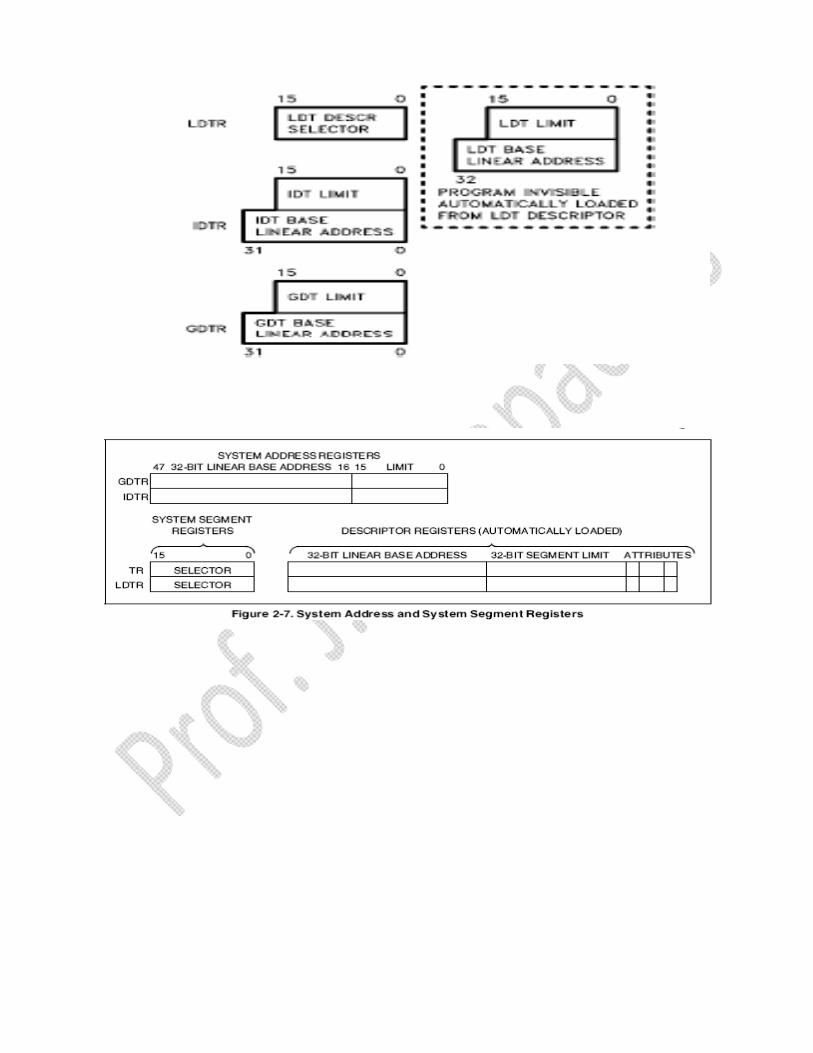
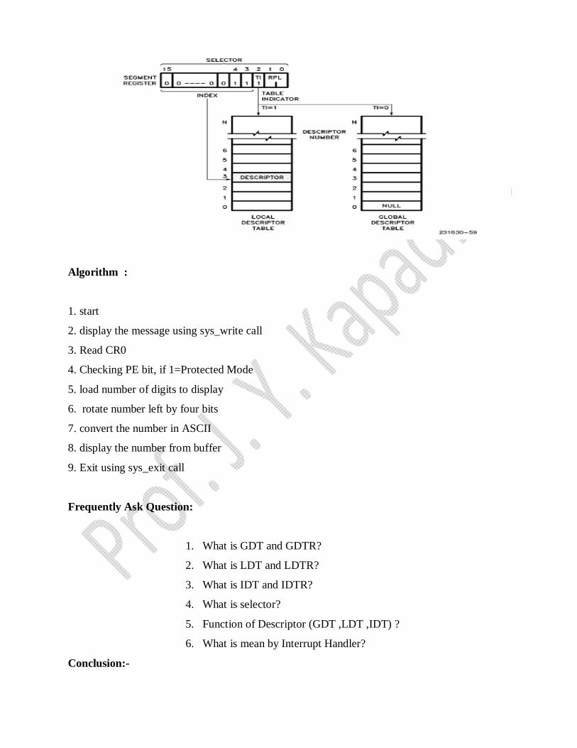
Global Descriptor Table Register
This register holds the 32-bit base address and 16-bit segment limit for the global descriptor table
(GDT). When a reference is made to data in memory, a segment selector is used to find a segment
descriptor in the GDT or LDT. A segment descriptor contains the base address for a segment.
Local Descriptor Table Register
This register holds the 32-bit base address, 16-bit segment limit, and 16-bit segment selector for the
local descriptor table (LDT). The segment which contains the LDT has a segment descriptor in the
GDT. There is no segment descriptor for the GDT. When a reference is made to data in memory, a
segment selector is used to find a segment descriptor in the GDT or
LDT. A segment descriptor contains the base address for a segment
Interrupt Descriptor Table Register
This register holds the 32-bit base address and 16-bit segment limit for the interrupt descriptor table
(IDT). When an interrupt occurs, the interrupt vector is used as an index to get a gate descriptor from
this table. The gate descriptor contains a far pointer used to start up the interruplhandler.
Algorithm :
1. start
2. display the message using sys_write call
3. Read CR0
4. Checking PE bit, if 1=Protected Mode
5. load number of digits to display
6. rotate number left by four bits
7. convert the number in ASCII
8. display the number from buffer
9. Exit using sys_exit call
Frequently Ask Question:
1. What is GDT and GDTR?
2. What is LDT and LDTR?
3. What is IDT and IDTR?
4. What is selector?
5. Function of Descriptor (GDT ,LDT ,IDT) ?
6. What is mean by Interrupt Handler?
Conclusion:-

Assignment No 07
Aim:
Write X86 program to sort the list of integers in ascending/descending order. Read the input from the
text file and write the sorted data back to the same text file using bubble sort
7.1 Software/Hardware Required:
Core 2 duo/i3/i5/i7 - 64bit processor Operating System – ubuntu/Fedora 64bit OS
Assembler: NASM
Editor Used – gedit
Theory :
Bubble sort, sometimes referred to as sinking sort, is a simple sorting algorithm that repeatedly steps through the list to be sorted, compares each pair of adjacent items and swaps them if they are in the wrong order. The pass through the list is repeated until no swaps are needed, which indicates that the list is sorted. The algorithm, which is a comparison sort, is named for the way smaller or larger elements "bubble" to the top of the list. Although the algorithm is simple, it is too slow and impractical for most problems even when compared to insertion sort.[2] It can be practical if the input is usually in sorted order but may occasionally have some out-of-order elements nearly in position.
Algorithm:--
i. Start
ii. Initialize all the sections needed in programming
iii. Display “Enter file name” message using Print macro expansion
iv. Accept file name using Accept macro and store in filename buffer
vi. Read character using Accept macro expansion
vii. Open file using fopen macro
viii. Compare RAX with -1H if equal then display error message “Error in
Opening File” with Print macro expansion else go to step ix
ix. Read content of opened file in buffer
x. Store file length in abuf_len
xi. Call Buff_array
xii. Stop
Algorithm 02
1) Initialize pointer ESI to file buffer
2) Initialize pointer EDI to array buffer
3) Initialize counter to some register
4) Read the Element From file one by one and store it into buffer
5) Increment ESI by 002 so point to next element
6) Increment edi by 01 to buffer
7) Check wheather count=0 yes stop otherwise repeat the steps go to step 01
8) Stop
Algorithm 03
1) Set counter to abuff_len minus 01
2) Set counter for no of iterations
3) Set counter for no of Comparisons
4) Set ESI to First Element And EDI to Next Element
5) Compare EDI and EDI if ESI element less than EDI Element then Skip jump to step 08
6) Otherwise use third variable swap.
7) Decrement comparison count by one
8) Increment ESI and EDI by 01
9) Compare if comparison count is zero
10) Decrement iteration count by 01
11) Go to Step no 04
12) Stop.

Assignment No.8
Aim:
Write X86 Menu driven Assembly Language Program (ALP) to implement OS (DOS) commands
TYPE, COPY and DELETE using file operations. User is supposed to provide command line
arguments in all cases.
8.1 Software/Hardware Required:
Core 2 duo/i3/i5/i7 - 64bit processor Operating System – ubuntu/Fedora 64bit OS
Assembler: NASM
Editor Used – gedit
8.2 THEORY:
Basics of Disk Operating System
An operating system (OS) is the software that controls a computer's hardware and peripheral devices
and allows other programs to function. Early computers did not have disk drives but were hard-wired to
carry out specific computations. Later, computers were able to store instructions loaded into the
computer's memory using punch cards and later magnetic tapes. Computer memory space was limited
and when the instructions to control a computer were moved onto a disk drive, such as a floppy disk or
internal hard drive, it was considered cutting-edge technology. Today, any modern operating system
would be considered a disk operating system.
Convert command into Computer actions
The structure of DOS
- The BIOS (Basic Input/Output System)
- The DOS kernel
- The command processor (shell)
MS-DOS Kernel
The kernel provides a collection of hardware-independent services called system functions.
- File Management
- Memory Management
- Device Input and Output
- Process control
@ The kernel is a proprietary program and provides a collection of hardware-independent services
called system functions.
@ These functions include the following:
◦ File and record management
◦ Memory management
◦ Character-device input/output
◦ Spawning of other programs
◦ Access to the real-time clock
The Command Processor
@ The command processor, or shell, is the user's interface to the operating system. It is responsible for
parsing (describing) and carrying out user commands, including the loading and execution of other
programs from a disk or other mass-storage device.
@ The default shell that is provided with MS-DOS is found in a file called COMMAND.COM. It is a
special class of program running under the control of MS-DOS.
User Commands
@ The user commands that are accepted by COMMAND.COM fall into three categories:
@ Internal commands
(carried out by code embedded in COMMAND.COM)
@ External commands
(names of programs stored on disk file)
@ Batch files
(batch or group of DOS commands)
Some of the Important DOS Commands:
1. TYPE COMMAND
Type: Internal
Syntax: TYPE [d:][path]filename Purpose: Displays the contents of a file.
Discussion when you use the TYPE command, the file is displayed with limited on-screen formatting.
Tabs are expanded and generally displayed as eight spaces wide. If you display files that contain special
(non-text) characters, these characters may have unpredictable effects on your dispaly. Wild card
characters (? and *) cannot be used with this command in either the filename or the extension.
2. COPY COMMAND
Type: Internal
Syntax:
COPY [/Y|-Y] [/A][/B] [d:][path]filename [/A][/B] [d:][path][filename] [/V]
or
COPY [/Y|-Y] [/A][/B] [d:][path]filename+[d:][path]filename[...] [d:][path][filename] [/V]
Purpose: Copies or appends files. Files can be copied with the same name or with a new name.
Discussion
COPY is usually used to copy one or more files from one location to another. However, COPY can also
be used to create new files. By copying from the keyboard console (COPY CON:) to the screen, files
can be created and then saved to disk. The first filename you enter is referred to as the source file. The
second filename you enter is referred to as the target file. If errors are encountered during the copying
process, the COPY program will display error messages using these names. Unlike the BACKUP
command, copied files are stored in the same format they are found in. The copied files can be used just
as you would use the original (whether the copied file is a data file or a program). COPY can also be
used to transfer data between any of the system devices. Files may also be combined during the copy
process.

3. DELETE COMMAND
Type: Internal Syntax: DEL (ERASE) [d:][path]filename [/P] Purpose: Deletes (erases) files from
disk. Discussion
You can use wildcard characters (? and *) to delete groups of files. If you don`t specify a pathname, the
program assumes the files to be deleted are on the drive and directory you are currently using. The /P
option prompts you to enter a Y or N for each file selected for deletion.
Conclusion:
Assignment No.10
Aim: Write 80387 ALP to find the roots of the quadratic equation. All the possible cases must be
considered in calculating the roots.
Software/Hardware Required:
Core 2 duo/i3/i5/i7 - 64bit processor
Operating System – ubuntu/Fedora 64bit OS
Assembler: NASM
Editor Used – gedit
Theory:
Explanation:
a) Features of 80387:
• High performance 80-Bit Internal Architecture
• Implements ANSI/IEEE standard 754-1985 for Binary floating-point arithmetic
• Expands Intel386DX CPU data types to include 32-, 64-, 80-bit floating point, 32-, 64-bit integers and
18-bit BCD operands
• Extends Intel386DX CPU instruction set to include Trigonometric, Logarithmic, Exponential and
Arithmetic instructions for all data types
• Upward object code compatible
• Full-range transcendental operations for SINE, COSINE, TANGENT, ARCTANGENT and
LOGARITHM
• Built-in Exception handling
• Operates independently in all modes of 80386
• Eight 80-bit Numeric registers
• Available in 68-pin PGA package
• One version supports 16MHz-33MHz
b) Block Diagram of 80387 Math co-processor,
b) Register Set
• Data registers: Eight 80-bit registers,
• Tag Word: the tag word marks the content of each numeric data register, two bits for each data
register
• Status word: the 16-bit status word reflects the overall state of the MCP

• Instruction and Data pointers: two pointer registers allows identification of the failing numeric
instruction which supply the address of failing numeric instruction and the address of its numeric
memory operand.
• Control Word: several processing options are selected by loading a control word from memory into
the control register
c) Instruction of co-processor used in the assignment:
FINIT: Initialise Co-processor
FLDZ: Load zero on stack top
FILD: Load Integer on stack
FIDIV: Divide stack top by an integer value
FIMUL: Multiply stack top by an integer value
FST: Store stack top
FADD: Add in stack top
FBSTP: Store integer part of stack top in 10 byte packed BCD format
FMUL: Multiply stack top
FSQRT: Square Root of Stack Top
FSTSW: Stores the coprocessor status word
FTS: compares ST0 and 0
d) Concept of Quadratic Equation:
The quadratic formula computes the solutions to the quadratic equation:
ax2 + bx + c = 0
The formula itself gives two solutions for x: x1 and x2.
_1, _2 = __± ____
__
The expression inside the square root (b2 − 4ac) is called the discriminant.
Its value is useful in determining which of the following three possibilities are true for the
solutions.
1. There is only one real degenerate solution. b2 − 4ac = 0
2. There are two real solutions. b2 − 4ac > 0
3. There are two complex solutions. b2 − 4ac < 0
Mathematical Model (Draw it by you own)
Flowchart (Draw it by your own)

Output: Display Roots of Quadratic Equation.
Main Algorithm:
i. Start
ii. Initialize a,b,c,four,two in data section
iii. Initialize the co-processor
i. Load b on stack top
ii. multiply top of stack with b
iii. Load a on stack
iv. Multiply stack top with c
v. Multiply stack top with four
vi. Subtract operand 1 from operand2 of stack
vii. Test stack top
viii. Store co-processor status word in AX
ix. Store AH value in Flag register
x. If top of stack is less than zero then jump to step xxi else continue
xi. Take square root of top of stack
xii. Store it in one variable let D (D=sqrt(b*b-4ac))
xiii. Subtract b from stacktop
xiv. Divide stack top by a and two
xv. Call Disp_result procedure to display root1
xvi. Load zero on stack top
xvii. Subtract D from Stacktop (i.e 0-D=-D)
xviii. Subtract b from stacktop
xix. Divide stack top by a and two
xx. Call Disp_result procedure to display root2
xxi. Display Message “No Real Solution” using Display macro
xxii. Stop
Macros:
Macro 1
1. Name : Display
2. Purpose: to display the messages by replacing the whole code by simple macro
declaration

3. I/P: sys_write call Number i.e rax=1, File descriptor (for Standard output rdi=1), Buffer
Address in rsi, and length of Buffer in rdx. Then Call syscall.
Procedure: 1
1. Name : Disp_result
2. Purpose : to convert 10 bit packed BCD result in Ascii
3. I/P : value of stack top
4. Algorithm for Procedures
i. Start
ii. Multiply stack top by 100. (Our numbers are having two digits after
decimal point)
iii. Store integer part of stack top in 10 byte packed BCD format using
Instruction FBSTP.
iv. Store stack top in resbuff of 10 byte
v. RSI point to the resbuff+9
vi. Mov value pointed by RSI in BL
vii. Rotate BL by 4
viii. Move BL in AL
ix. And AL with 0FH
x. Compare AL with 0
xi. If not equal then go to step xiv else continue
xii. Print “+” using display Macro
xiii. Jump to step xv
xiv. Print “-” using display Macro
xv. Rotate BL by 4
xvi. Push RSI
xvii. Call disp8num procedure (Print first byte after sign)
xviii. Pop RSI
xix. Dec RSI
xx. Initialize counter RCX by 8 (8byte before decimal point)
xxi. Save RCX and RSI on stack
xxii. Move value pointed by RSI in BL register
xxiii. Call disp8num procedure
xxiv. Pop RSI and RCX
xxv. Decrement RSI
xxvi. If RCX is not equal to zero Repeat step from xxi else continue
xxvii. Print decimal point using Display macro
xxviii. Move value pointed by RSI in BL register
xxix. Call disp8num procedure
xxx. Ret
xxxi. Stop
Procedure 2
1. Name : disp8num
2. Purpose : Convert 2 digit hex result into 2 Ascii character to display numbers
3. I/P : BL register value
4. Algorithm for Procedures
a. Move RSI with effective address of dispbuff.
b. Initialize rcx by 2
c. Rotate the contents of bl to the left side by 4 bits.
d. Move the contents of bl into al
e. And the contents of al with 0fH
f. Compare al with 09h
i. If al is below or equal then add 30H in al
ii. Else add 37H in al
g. Move the content of al into memory pointed by RSI
h. Increment RSI
i. Repeat from step c to h until rcx is not equal to 0
j. Expand macro print with the parameters dispbuff & 2.
k. return
Conclusions:
Assembly Level Program to find the roots of the quadratic equation using 80387 is assembled
and executed successfully.
Frequently Asked Question (Answer following Question)
Q1 Explain the following 80387 instruction with one example of each:
a. Data transfer group

b. Non- Transcendental (Arithmetic group)
c. Comparison group
d. Transcendental (Trigonometry and Exponential) group
e. Processor control group
Q2 Explain 80387 Data Type
Q3 Explain and draw Instruction Queue, Data Registers, Status Registers, and Control
Registers of 80387 in detail
Q4 Draw Interfacing diagram of 80387 with 80386
Assignment No 11
Aim: Write 80387 ALP to plot Sine Wave, Cosine Wave. Access video memory directly for
plotting.
Software/Hardware Required:
Core 2 duo/i3/i5/i7 - 64bit processor
Operating System – ubuntu/Fedora 64bit OS
Assembler: NASM
Editor Used – gedit
Theory:
Explanation:
VGA Mode 13h Graphics: Mode 13h is a standard VGA graphics mode. While it may seem
somewhat limited in resolution and colors when compared to SVGA modes, it is supported on
nearly every computer available today. There are 320 pixels over and 200 pixels down the
screen, each of which may have one of 256 colors. Mode 13h is unique from other higher
resolution, but only 16-color, VGA graphics modes because the memory for the video screen is
arranged linearly, where one byte corresponds to one pixel on the screen. As a result, Mode 13h
is very easy to program in since it’s not necessary to deal with bit planes.
The first step to making a Mode 13h program is to call a BIOS interrupt to enter it. Do this by:
mov ax, 0013h
int 10h
To return back to text at the end of the program, use:
mov ax, 0003h
int 10h
Once in Mode 13h, each pixel can be set to any color from a palette of 256 colors. There are two
methods to do this by—using BIOS interrupts or direct writes. Direct writes are the best choice
here due to the simplicity of Mode 13h (the bit planes used in other VGA modes can make BIOS
interrupts the best choice). Since each pixel directly corresponds to one byte, just set the byte to
the color (0 - 255).
Use the following formula to determine the address and move a byte into it: Offset = (320 * Y)+

X
The following code fragment illustrates how to set a pixel:
; Before drawing graphics
mov ax, 0A000h ; Set ES to graphics screen segment
mov es, ax ;(set X and Y and DL to the color)
imul di, [Y], 320 ; Multiply Y by 320 and store in DI
add di, [X] ; Add the X coordinate
mov [es:di], dl ; Set the pixel to the color specified by DL
This method can be much faster than BIOS, because for most things, only a few IMUL
instructions should be needed and the majority of pixels can be set by moving relative to the
original address. For example, to move left or right, simply subtract or add 1 from the address,
and to move up and down, subtract or add 320, respectively.
CALCULATION OF SINE WAVE: Y = 100 – 60 sin ({pi/180}*x)
CALCULATION OF COSINE WAVE: Y = 100 – 60 cos ({pi/180}*x)
Instruction of co-processor used in the assignment: (Explain it by your own)
FIMUL:
FSIN:
FLDPI:
FIDIV:
FSUB:
FILD:
FISTP:
Mathematical Model (Draw it by your own)
Flowchart (Draw it by your own)
Output: Display Sine wave and Cos wave.
Algorithm for Plotting Sine wave:
i. Start
ii. Initialize x=0.0, xadd=6.0, one80=180.0,count=320,x1=0,ycursor=0 in data segment.
iii. Initialize DS (needed for .exe-program) mov ax,@data and mov ds, ax
iv. Move address of video memory 0A000H in AX and the Move AX in ES
v. Select Desired video mode Here we selected mode 13H (320x200 256 color graphics
(MCGA,VGA)). For this Move AX=13H [or AH=00 (Set Video mode) and AL=13H (Video mode)]
and then call int 10H BIOS interrupt to enter in 13H mode
vi. Initialize CX with zero (X=0 i.e. angle)
vii. Push CX
viii. Call get_sine procedure
ix. Move CX in BX
x. Call vector_to_memory procedure
xi. Move AX in DI (Offset for pixel)
xii. Move color of pixel (0-255) in AL
xiii. Put pixel directly in video RAM by Moving AL at the address given by ES:DI
xiv. Pop CX
xv. Increment CX
xvi. Compare CX with 320 (right boarder of screen) If not equal then go to step vii else continue
xvii. Display message “Sine Wave:” by passing 09h in AH, address of message in DX and call int 21h
xviii. Wait for any key press, move 0 in AH and then call interrupt 16H
xix. For switching back to text mode from graphic mode, move 3 in AX and then call interrupt 10H
xx. For Exit, Move 4CH in AH and then call interrupt 21 H
xxi. Stop
Algorithm for Plotting Cosine wave:
i. Start
ii. Initialize x=0.0, xadd=6.0, one80=180.0,count=320,x1=0,ycursor=0 in data segment.
iii. Initialize DS (needed for .exe-program) mov ax,@data and mov ds, ax
iv. Move address of video memory 0A000H in AX and the Move AX in ES
v. Select Desired video mode Here we selected mode 13H (320x200 256 color graphics
(MCGA,VGA)). For this Move AX=13H [or AH=00 (Set Video mode) and AL=13H (Video mode)]
and then call int 10H BIOS interrupt to enter in 13H mode
vi. Initialize CX with zero (X=0 i.e. angle)
vii. Push CX
viii. Call get_cos procedure
ix. Move CX in BX
x. Call vector_to_memory procedure

xi. Move AX in DI (Offset for pixel)
xii. Move color of pixel (0-255) in AL
xiii. Put pixel directly in video RAM by Moving AL at the address given by ES:DI
xiv. Pop CX
xv. Increment CX
xvi. Compare CX with 320 (right boarder of screen) If not equal then go to step vii else continue
xvii. Display message “Cos Wave:” by passing 09h in AH, address of message in DX and call int 21h
xviii. Wait for any key press, move 0 in AH and then call interrupt 16H
xix. For switching back to text mode from graphic mode, move 3 in AX and then call interrupt 10H
xx. For Exit, Move 4CH in AH and then call interrupt 21 H Stop
Procedure: 1
1. Name : get_sine
2. Purpose : to calculate sin(x) using 80387
3. I/P : Angle
4. O/P: Y=100 – 60 sin ({pi/180}*x)
5. Algorithm for Procedures
i. Start
ii. Initialize the co-processor
iii. Move CX in X (angle)
iv. Load pi on stack top
v. Multiply top of stack by x
vi. Divide top of stack by 180
vii. Calculate sine of top of stack using FSIN instruction
viii. Multiply stack top by 60 (Scaling)
ix. Load 100 on stack top ( for Negative cycle)
x. Subtract ST(1) from ST(0)
xi. Store top in rint variable
xii. ret
xiii. Stop
Procedure: 2
1. Name : get_cos
2. Purpose : to calculate sin(x) using 80387
3. I/P : Angle
4. O/P: Y=100 – 60 cos ({pi/180}*x)
5. Algorithm for Procedures
i. Start
ii. Initialize the co-processor
iii. Move CX in X (angle)
iv. Load pi on stack top
v. Multiply top of stack by x
vi. Divide top of stack by 180
vii. Calculate Cosine of top of stack using FCOS instruction
viii. Multiply stack top by 60 (Scaling)
ix. Load 100 on stack top ( for Negative cycle)
x. Subtract ST(1) from ST(0)
xi. Store top in rint variable
xii. ret
xiii. Stop
Procedure: 3
1. Name : vector_to_memory
2. Purpose : to calculate offset=Y*320+X
3. I/P : Args: BX = X, AX = Y
4. O/P: Y=100 – 60 cos ({pi/180}*x)
5. Algorithm for Procedures
i. Push DX (mul changes dx too)
ii. Move width of video memory in CX. Here resolution is 320X200 So CX=320
iii. Multiply AX by CX (DX:AX = AX * CX i.e Y*320)
iv. ADD AX and BX (offset=Y*320+X)
v. Pop DX
vi. ret
Conclusions:

Frequently Asked Question (Answer following Question)
Q1. Explain the following System Calls
INT 10h / AH = 0 - set video mode.
input:
AL = desired video mode.
these video modes are supported:
AH = 00
AL = 00H 40x25 B/W text (CGA,EGA,MCGA,VGA)
= 01H 40x25 16 color text (CGA,EGA,MCGA,VGA)
= 02H 80x25 16 shades of gray text (CGA,EGA,MCGA,VGA)
= 03H 80x25 16 color text (CGA,EGA,MCGA,VGA)
= 04H 320x200 4 color graphics (CGA,EGA,MCGA,VGA)
= 05H 320x200 4 color graphics (CGA,EGA,MCGA,VGA)
= 06H 640x200 B/W graphics (CGA,EGA,MCGA,VGA)
= 07H 80x25 Monochrome text (MDA,HERC,EGA,VGA)
= 08H 160x200 16 color graphics (PCjr)
= 09H 320x200 16 color graphics (PCjr)
= 0AH 640x200 4 color graphics (PCjr)
= 0BH Reserved (EGA BIOS function 11)
= 0CH Reserved (EGA BIOS function 11)
= 0DH 320x200 16 color graphics (EGA,VGA)
= 0EH 640x200 16 color graphics (EGA,VGA)
= 0FH 640x350 Monochrome graphics (EGA,VGA)
= 10H 640x350 16 color graphics (EGA or VGA with 128K)
640x350 4 color graphics (64K EGA)
= 11H 640x480 B/W graphics (MCGA,VGA)
= 12H 640x480 16 color graphics (VGA)
= 13H 320x200 256 color graphics (MCGA,VGA)
Example:
mov al, 13h
mov ah, 0
int 10h
INT 16h - use of keyboard: This interrupt is used both for reading characters from keyboard and
for obtaining keyboard’s current state (Caps Lock, Ctrl, Shift etc.).
Function 00h (in AH) is used to read a character from the keyboard, the character will be
returned in AL.
INT 21h / AH=9 - output of a string at DS:DX. String must be terminated by
'$'.
example:
org 100h
mov dx, offset msg
mov ah, 9
int 21h
ret
msg db "hello world $"
INT 21h / AH=0Ch - flush keyboard buffer and read standard input.
entry: AL = number of input function to execute after flushing buffer (can be 01h,06h,07h,08h,
or 0Ah - for other values the buffer is flushed but no input is attempted); other registers as
appropriate for the selected input function.

Assignment 12:
Problem Definition:
Write 8087 ALP to obtain:
(i) Mean (ii) Variance (iii) Standard Deviation
For a given set of data elements defined in data segment. Also display result.
Theory:
8087 is numeric data processor (NDP) called as math co-processor. It supports 68
instructions.Instruction set includes both simple and complex floating point instructions. By interfacing
8087 NDP with 8086 processor, programmer can perform various powerful arithmetic floating point
operations. e.g. add, sub, div, square root, logarithm etc.
8087 has two major sections:
1. Control unit 2. Numeric Execution unit (NEU)
Control unit:This interface the coprocessor to the microprocessor. This unit receives the instruction
and decodes it also read and write the memory operands. It monitors the instruction stream, if the
instruction is an ESCape (coprocessor) instruction, the coprocessor executes it; if not the
microprocessor executes it.
Numeric Execution units (NEU):Thisexecutes all the numeric processor instructions.It has 8 register
(80 bit) stacks that hold the operands for arithmetic instructions & the result.Instruction either address
data in specific stack data – register or uses push and pop mechanism to store and retrieve data.
Mathematical Modeling
S= {s,e,a,b, Fme, FF,MEM shared}
1. S : S is distinct start of program
S -> Global _start
_start:
2. e: e is distinct end of program
mov eax,1
movebx ,0

int 80h
3. a: It is input of program
a-> 1) Array of floating point numbers
2) Array count
4. b: It is an output of program
b-> 1) Mean
2) Standard Deviation
3) Variance
6. FF: The system enters in a valid state as there are no inputs from user in this program so system
have no invalid state.
7. MEM shared: This is memory shared in the program. We have used the shared
memory in the following.
I. disp8_proc
II. dispres
Instructions Used:
1. FLD: This loads floating-point memory data to the top of the internal stack.
2. FLDZ: This pushes 0.0 on to stack.
3. FST: This stores a copy of the top of the stack to the memory location or coprocessor register
indicated by the operand.
4. FINIT: Performs a reset (initialize) operation on the arithmetic coprocessor.
5. FADD: Adds real number from specified source to specified real number at destination.
6. FIDIV: Divide ST by integer from memory and put result in ST.
7. FSUB: Subtracts real number from specified source from specified real number at destination
and puts result in the specified destination.
8. FMUL: Multiply real number from source by real number from specified destination and put
result in specified stack element.
9. FSQRT: Finds the square root of the top of the stack and leaves the resultant square root at the
top of the stack.
Algorithm:
32. Start

33. Initialize data section.
34. Initialize floating point unit that is 8087using FINIT.
35. Push 0.0 onto stack using FLDZ.
36. Move count of array in RCX register.
37. Move array in RBX register.
38. Locate first location of array of numbers in pointer register.
39. Add the element ofarraypointed bypointerregister to RBX.
40. Increment Location Pointer Register and go to step 8 and repeat till RCX becomes zero.
41. Store the mean using FST.
42. Make RCX count zero and again load array count in RCX and array element in RBX.
43. Make location pointer RSI also zero.Push 0.0 onto stack using FLDZ.
44. Loads floating-point memory data in RBX that is array element to the top of the internal stack
using FLD.
45. Subtract mean from array element.
46. Stores a copy of the top of the stack to the coprocessor register indicated by the operand that is
ST(1).
47. Multiply result of subtraction with itself using FMUL and add it to the top of stack.
48. Increment RSI and decrement counter RCX and go to step 13.
49. Divide result on top of stack by integer array count and put result in ST that is top of stack.
50. Store the result of division in variance.
51. Finds the square root of the top of the stack and leaves the resultant square root at the top of the
stack.
52. Call display procedure to display result of square root.
53. Stop.
Conclusion: