Embed Size (px)
Citation preview

Symposium for Combustion Control 2018 1
Assessment of Water Injection in a SI Engine
using a Fast Running Detailed Chemistry
Based Combustion Model
Tim Franken, Corinna Netzer, Michal Pasternak and Fabian Mauß Brandenburg University of Technology Cottbus-Senftenberg, Cottbus, Germany
Lars Seidel LOGE Deutschland GmbH, Cottbus, Germany
Anders Borg and Harry Lehtiniemi LOGE AB, Lund, Sweden
Andrea Matrisciano Chalmers University of Technology, Göteborg, Sweden
Andre Kulzer Porsche AG, Stuttgart, Germany
Summary
Water injection is investigated for turbocharged spark ignition engines to limit knock
probability and therefore enable higher engine efficiency. This work presents an
integrated simulation-based optimization process to assess water injection. The fast
running quasi-dimensional stochastic reactor model is coupled with tabulated
chemistry to account for water effects on laminar flame speed and combustion
chemistry. The increase of the compression ratio and the shift of the spark timing to
earlier crank angles are most beneficial for fuel consumption. Wherefore, the limitation
of the compression ratio and the shift of the retarded spark timing are better for low
knock probability. Overall, the water presence shows a decrease of fuel consumption
and knock probability at the same time. The application of the quasi-dimensional
stochastic reactor model with tabulated chemistry reduces the computational costs and
is suitable for multi-objective optimizations.
1 Introduction
Today we experience the revival of water injection as a key technology for
turbocharged, spark ignition (SI) engines [1]. It enables higher boost pressures and
compression ratios, which results in increased engine efficiency [2]. The rising number
of optimization parameters pushes the traditional test bench approach to its limits and
demands sophisticated simulation tools to support the engine development and pre-
calibration.
Detailed three-dimensional (3D) computational fluid dynamic (CFD) studies of water
injection in gasoline engines are published by Berni et al. [3] and Netzer et al. [4]. The
group of Berni et al. focused on the application of 3D CFD to investigate a specific

2 Symposium for Combustion Control 2018
water injection concept. They show the feasibility of the simulation approach to
evaluate water effects on thermodynamic conditions and auto-ignition. Netzer et al.
emphasize the necessity to use detailed chemistry in 3D CFD simulations, to separate
physical from chemical water effects. The authors found that water effects on laminar
flame speed and combustion chemistry are not negligible. Furthermore, the 3D CFD
results state the strong influence of water injection and vaporization on the local
distribution of temperature and auto-ignition hot spots within the cylinder.
The physics-based quasi-dimensional (QD) SI stochastic reactor model (SRM)
accounts for the mixture and temperature in-homogeneities within the cylinder [5, 6, 7,
8]. This approach allows to predict local effects of fuel composition on flame
propagation, auto-ignition and emission formation. The QD SRM was already applied
to investigate the effect of different octane number fuels on auto-ignition in the
unburned zone as shown by Netzer et al. [9]. The detailed chemistry for multi-
component fuels used in that work as well as in the presented work is based on the
methodology of reaction mechanism development and reduction introduced by Seidel
et al. [10, 11]. To reduce the computational cost of the QD SRM simulations,
Matrisciano et al. published a reaction-progress-variable-based tabulation strategy
[12]. Thereby, the detailed chemistry is pre-compiled in a look-up table based on
thermodynamic conditions and reaction progress variable.
This work presents a simulation-based optimization method including the QD SRM with
dual fuel (gasoline and water) tabulated chemistry and the optimization tool
modeFRONTIER [13]. A multi-objective optimization process is defined to reduce fuel
consumption and knock probability of a SI engine operating point by water presence
and compression ratio increment. The first section introduces the simulation
methodology to optimize the SI engine operating point. Following, the numerical test
case is defined, and the optimization results are discussed.
2 Simulation Method
In the engine development process, the prototype engine and its base calibration must
be tested for many operating conditions. Therefore, an integrated process based on
detailed 3D CFD models, fast running two-zone QD SRM and multi-objective
optimization tools can be incorporated (see Figure 1).
The detailed chemistry and its sensitivity to water presence is the fundament for the
process since it will be applied to 3D CFD and QD SRM simulations. The 3D CFD data
for turbulent kinetic energy 𝑘𝐶𝐹𝐷 is used as input data for the QD SRM mixing time 𝜏𝑆𝑅𝑀
in equation (1):
𝜏𝑆𝑅𝑀 = 𝐶𝜙 ⋅(
6 ⋅ 𝑉𝜋 )
13
√𝑘𝐶𝐹𝐷
(1)
Symposium for Combustion Control 2018 3
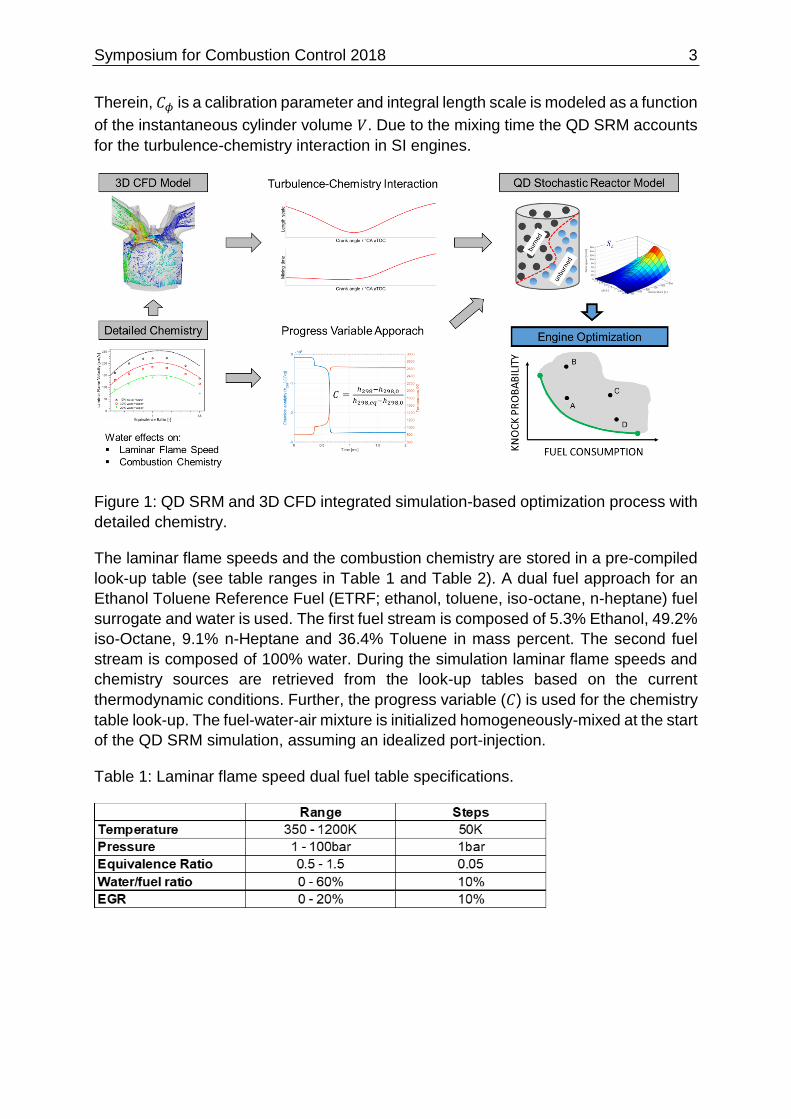
Therein, 𝐶𝜙 is a calibration parameter and integral length scale is modeled as a function
of the instantaneous cylinder volume 𝑉. Due to the mixing time the QD SRM accounts
for the turbulence-chemistry interaction in SI engines.
Figure 1: QD SRM and 3D CFD integrated simulation-based optimization process with
detailed chemistry.
The laminar flame speeds and the combustion chemistry are stored in a pre-compiled
look-up table (see table ranges in Table 1 and Table 2). A dual fuel approach for an
Ethanol Toluene Reference Fuel (ETRF; ethanol, toluene, iso-octane, n-heptane) fuel
surrogate and water is used. The first fuel stream is composed of 5.3% Ethanol, 49.2%
iso-Octane, 9.1% n-Heptane and 36.4% Toluene in mass percent. The second fuel
stream is composed of 100% water. During the simulation laminar flame speeds and
chemistry sources are retrieved from the look-up tables based on the current
thermodynamic conditions. Further, the progress variable (𝐶) is used for the chemistry
table look-up. The fuel-water-air mixture is initialized homogeneously-mixed at the start
of the QD SRM simulation, assuming an idealized port-injection.
Table 1: Laminar flame speed dual fuel table specifications.
4 Symposium for Combustion Control 2018
Table 2: Combustion chemistry dual fuel table specifications.
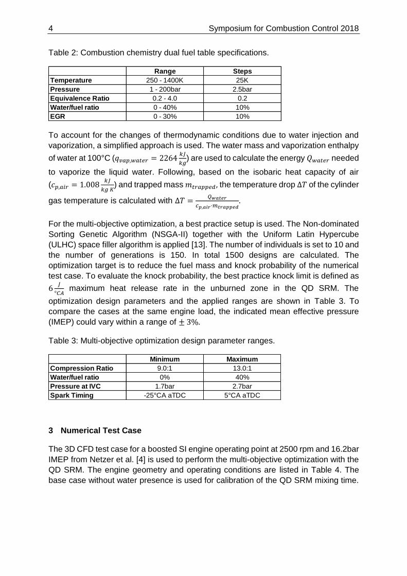
To account for the changes of thermodynamic conditions due to water injection and
vaporization, a simplified approach is used. The water mass and vaporization enthalpy
of water at 100°C (𝑞𝑣𝑎𝑝,𝑤𝑎𝑡𝑒𝑟 = 2264𝑘𝐽
𝑘𝑔) are used to calculate the energy 𝑄𝑤𝑎𝑡𝑒𝑟 needed
to vaporize the liquid water. Following, based on the isobaric heat capacity of air
(𝑐𝑝,𝑎𝑖𝑟 = 1.008𝑘𝐽
𝑘𝑔 𝐾) and trapped mass 𝑚𝑡𝑟𝑎𝑝𝑝𝑒𝑑, the temperature drop Δ𝑇 of the cylinder
gas temperature is calculated with Δ𝑇 =𝑄𝑤𝑎𝑡𝑒𝑟
𝑐𝑝,𝑎𝑖𝑟⋅𝑚𝑡𝑟𝑎𝑝𝑝𝑒𝑑.
For the multi-objective optimization, a best practice setup is used. The Non-dominated
Sorting Genetic Algorithm (NSGA-II) together with the Uniform Latin Hypercube
(ULHC) space filler algorithm is applied [13]. The number of individuals is set to 10 and
the number of generations is 150. In total 1500 designs are calculated. The
optimization target is to reduce the fuel mass and knock probability of the numerical
test case. To evaluate the knock probability, the best practice knock limit is defined as
6𝐽
°𝐶𝐴 maximum heat release rate in the unburned zone in the QD SRM. The
optimization design parameters and the applied ranges are shown in Table 3. To
compare the cases at the same engine load, the indicated mean effective pressure
(IMEP) could vary within a range of ± 3%.
Table 3: Multi-objective optimization design parameter ranges.
3 Numerical Test Case
The 3D CFD test case for a boosted SI engine operating point at 2500 rpm and 16.2bar
IMEP from Netzer et al. [4] is used to perform the multi-objective optimization with the
QD SRM. The engine geometry and operating conditions are listed in Table 4. The
base case without water presence is used for calibration of the QD SRM mixing time.
Range Steps
Temperature 250 - 1400K 25K
Pressure 1 - 200bar 2.5bar
Equivalence Ratio 0.2 - 4.0 0.2
Water/fuel ratio 0 - 40% 10%
EGR 0 - 30% 10%
Minimum Maximum
Compression Ratio 9.0:1 13.0:1
Water/fuel ratio 0% 40%
Pressure at IVC 1.7bar 2.7bar
Spark Timing -25°CA aTDC 5°CA aTDC
Symposium for Combustion Control 2018 5
Additionally, three operating points with different spark timings, water/fuel (w/f) ratios
(20%, 50% and 80% w/f ratio) and IMEPs are used to validate the QD SRM.
Table 4: Engine geometry and operating conditions for the base case without water
presence.
4 Simulation Results
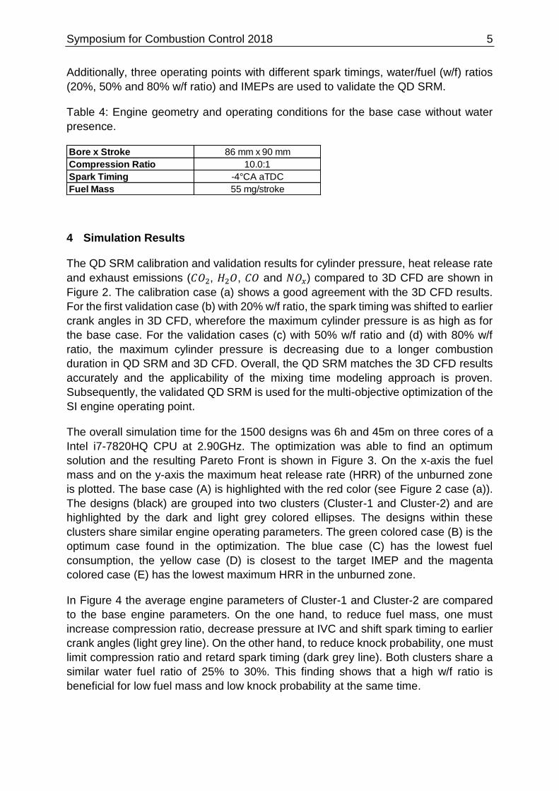
The QD SRM calibration and validation results for cylinder pressure, heat release rate
and exhaust emissions (𝐶𝑂2, 𝐻2𝑂, 𝐶𝑂 and 𝑁𝑂𝑥) compared to 3D CFD are shown in
Figure 2. The calibration case (a) shows a good agreement with the 3D CFD results.
For the first validation case (b) with 20% w/f ratio, the spark timing was shifted to earlier
crank angles in 3D CFD, wherefore the maximum cylinder pressure is as high as for
the base case. For the validation cases (c) with 50% w/f ratio and (d) with 80% w/f
ratio, the maximum cylinder pressure is decreasing due to a longer combustion
duration in QD SRM and 3D CFD. Overall, the QD SRM matches the 3D CFD results
accurately and the applicability of the mixing time modeling approach is proven.
Subsequently, the validated QD SRM is used for the multi-objective optimization of the
SI engine operating point.
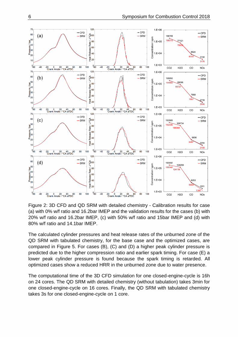
The overall simulation time for the 1500 designs was 6h and 45m on three cores of a
Intel i7-7820HQ CPU at 2.90GHz. The optimization was able to find an optimum
solution and the resulting Pareto Front is shown in Figure 3. On the x-axis the fuel
mass and on the y-axis the maximum heat release rate (HRR) of the unburned zone
is plotted. The base case (A) is highlighted with the red color (see Figure 2 case (a)).
The designs (black) are grouped into two clusters (Cluster-1 and Cluster-2) and are
highlighted by the dark and light grey colored ellipses. The designs within these
clusters share similar engine operating parameters. The green colored case (B) is the
optimum case found in the optimization. The blue case (C) has the lowest fuel
consumption, the yellow case (D) is closest to the target IMEP and the magenta
colored case (E) has the lowest maximum HRR in the unburned zone.
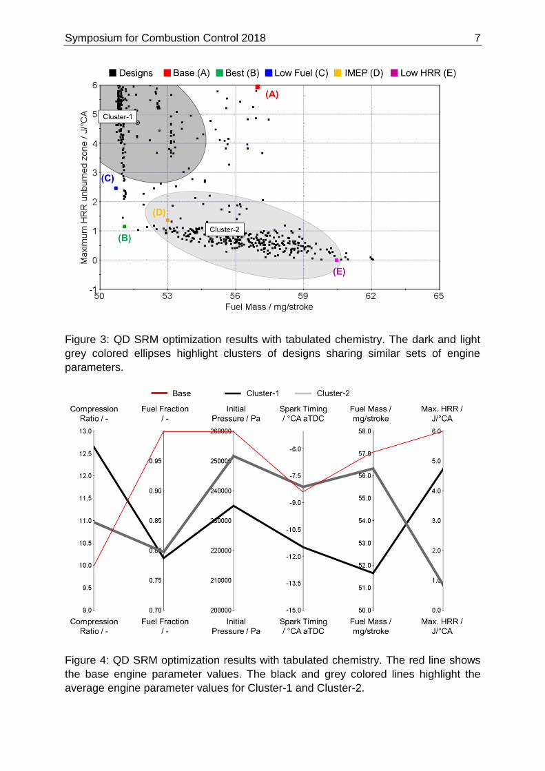
In Figure 4 the average engine parameters of Cluster-1 and Cluster-2 are compared
to the base engine parameters. On the one hand, to reduce fuel mass, one must
increase compression ratio, decrease pressure at IVC and shift spark timing to earlier
crank angles (light grey line). On the other hand, to reduce knock probability, one must
limit compression ratio and retard spark timing (dark grey line). Both clusters share a
similar water fuel ratio of 25% to 30%. This finding shows that a high w/f ratio is
beneficial for low fuel mass and low knock probability at the same time.
Bore x Stroke 86 mm x 90 mm
Compression Ratio 10.0:1
Spark Timing -4°CA aTDC
Fuel Mass 55 mg/stroke
6 Symposium for Combustion Control 2018
Figure 2: 3D CFD and QD SRM with detailed chemistry - Calibration results for case
(a) with 0% w/f ratio and 16.2bar IMEP and the validation results for the cases (b) with
20% w/f ratio and 16.2bar IMEP, (c) with 50% w/f ratio and 15bar IMEP and (d) with
80% w/f ratio and 14.1bar IMEP.
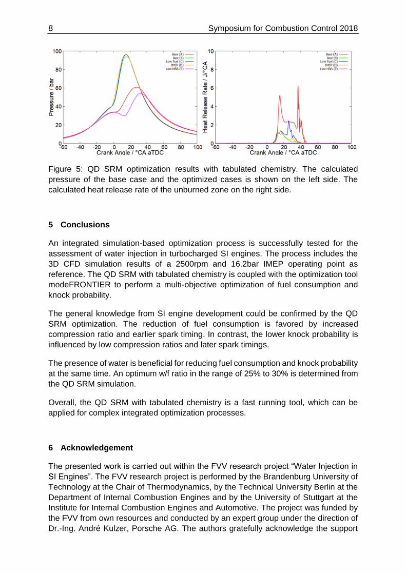
The calculated cylinder pressures and heat release rates of the unburned zone of the
QD SRM with tabulated chemistry, for the base case and the optimized cases, are
compared in Figure 5. For cases (B), (C) and (D) a higher peak cylinder pressure is
predicted due to the higher compression ratio and earlier spark timing. For case (E) a
lower peak cylinder pressure is found because the spark timing is retarded. All
optimized cases show a reduced HRR in the unburned zone due to water presence.
The computational time of the 3D CFD simulation for one closed-engine-cycle is 16h
on 24 cores. The QD SRM with detailed chemistry (without tabulation) takes 3min for
one closed-engine-cycle on 16 cores. Finally, the QD SRM with tabulated chemistry
takes 3s for one closed-engine-cycle on 1 core.
Symposium for Combustion Control 2018 7
Figure 3: QD SRM optimization results with tabulated chemistry. The dark and light
grey colored ellipses highlight clusters of designs sharing similar sets of engine
parameters.
Figure 4: QD SRM optimization results with tabulated chemistry. The red line shows
the base engine parameter values. The black and grey colored lines highlight the
average engine parameter values for Cluster-1 and Cluster-2.
8 Symposium for Combustion Control 2018
Figure 5: QD SRM optimization results with tabulated chemistry. The calculated
pressure of the base case and the optimized cases is shown on the left side. The
calculated heat release rate of the unburned zone on the right side.
5 Conclusions
An integrated simulation-based optimization process is successfully tested for the
assessment of water injection in turbocharged SI engines. The process includes the
3D CFD simulation results of a 2500rpm and 16.2bar IMEP operating point as
reference. The QD SRM with tabulated chemistry is coupled with the optimization tool
modeFRONTIER to perform a multi-objective optimization of fuel consumption and
knock probability.
The general knowledge from SI engine development could be confirmed by the QD
SRM optimization. The reduction of fuel consumption is favored by increased
compression ratio and earlier spark timing. In contrast, the lower knock probability is
influenced by low compression ratios and later spark timings.
The presence of water is beneficial for reducing fuel consumption and knock probability
at the same time. An optimum w/f ratio in the range of 25% to 30% is determined from
the QD SRM simulation.
Overall, the QD SRM with tabulated chemistry is a fast running tool, which can be
applied for complex integrated optimization processes.
6 Acknowledgement
The presented work is carried out within the FVV research project “Water Injection in
SI Engines”. The FVV research project is performed by the Brandenburg University of
Technology at the Chair of Thermodynamics, by the Technical University Berlin at the
Department of Internal Combustion Engines and by the University of Stuttgart at the
Institute for Internal Combustion Engines and Automotive. The project was funded by
the FVV from own resources and conducted by an expert group under the direction of
Dr.-Ing. André Kulzer, Porsche AG. The authors gratefully acknowledge the support

Symposium for Combustion Control 2018 9
received from the Research Association for Combustion Engines (FVV) eV and from
all project participants.
7 References
[1] B. Durst, G. Unterweger, S. Rubbert, A. Witt and M. Böhm, "Thermodynamic
effects of water injection on Otto Cycle engines with different water injection
systems," in The Working Process of the Internal Combustion Engine, Graz,
2015.
[2] F. Bozza, V. De Bellis and L. Teodosio, "Potentials of cooled EGR and water
injection for knock resistance and fuel consumption improvements of gasoline
engines," Applied Energy, vol. 169, pp. 112-125, 2016.
[3] F. Berni, S. Breda, M. Lugli and G. Cantore, "A Numerical Investigation on the
Potentials of Water Injection to Increase Knock Resistance and Reduce Fuel
Consumption in Highly Downsized GDI Engines," Energy Procedia, vol. 81, pp.
826-835, 2015.
[4] C. Netzer, T. Franken, L. Seidel, H. Lehtiniemi and F. Mauss, "Numerical Analysis
of the Impact of Water Injection on Combustion and Thermodynamics in a
Gasoline Engine using Detailed Chemistry," in SAE Technical Paper, 2018.
[5] M. Pasternak, F. Mauss, M. Sens, M. Riess, A. Benz and K. G. Stapf, "of a
Turbocharged Gasoline Engine under High Load Condition of a Turbocharged
Gasoline Engine under High Load Condition stochastic reactor model and three-
dimensional computational fluid dynamics engine model," International J of
Engine Research, vol. 17, no. 1, p. 76–85, 2016.
[6] M. Sens, A. Benz, M. Riess, F. G. Lage, X. S. Bjerkborn, F. Mauss and M.
Pasternak, "Multiple Spark Plug Approach: Potential for Future Highly Diluted
Spark Ignited Combustion," in SIA Powertrain, Versailles, 2015.
[7] M. Pasternak, C. Netzer, F. Mauss, M. Fischer, M. Sens and M. Riess,
"Simulation of the Effects of Spark Timing and External EGR on Gasoline
Combustion Under Knock-Limited Operation at High Speed and Load," in
Knocking in Gasoline Engines, Berlin, 2017.
[8] LOGE AB, "LOGEsoft Manual v1.08," 2016. [Online]. Available:
www.logesoft.com.
10 Symposium for Combustion Control 2018
[9] C. Netzer, L. Seidel, M. Pasternak, C. Klauer, C. Perlman, F. Ravet and F. Mauss,
"Engine Knock Prediction and Evaluation Based on Detonation Theory Using a
Quasi-Dimensional Stochastic Reactor Model," SAE Technical Paper, 2017.
[10] L. Seidel, Development and Reduction of a Multicomponent Reference Fuel for
Gasoline, Cottbus: Brandenburg University of Technology Cottbus-Senfenberg,
2017.
[11] L. Seidel, C. Netzer, M. Hilbig, F. Mauss, C. Klauer, M. Pasternak and A.
Matrisciano, "Systematic Reduction of Detailed Chemical Reaction Mechanisms
for Engine Applications," Journal of Engineering for Gas Turbines and Power, vol.
139, no. 9, 2017.
[12] A. Matrisciano, T. Franken, C. Perlman, A. Borg, H. Lehtiniemi and F. Mauss,
"Development of a Computationally Effcient Progress Variable Approach for a
Direct Injection Stochastic Reactor Model," SAE Technical Paper, 2017.
[13] ESTECO, "modeFRONTIER User Guide 2017R4," 2017. [Online]. Available:
https://www.esteco.com/modefrontier.