Embed Size (px)
Citation preview

Assessment of overheating risk in gynaecology scanning rooms during near-heatwave conditions: a case study of the Royal Berkshire Hospital in the UK
Article
Published Version
Creative Commons: Attribution 4.0 (CC-BY)
Open Access
Gough, H., Faulknall-Mills, S., King, M.-F. and Luo, Z. (2019) Assessment of overheating risk in gynaecology scanning rooms during near-heatwave conditions: a case study of the Royal Berkshire Hospital in the UK. International Journal of Environmental Research and Public Health, 16 (18). 3347. ISSN 1660-4601 doi: https://doi.org/10.3390/ijerph16183347 Available at http://centaur.reading.ac.uk/85558/
It is advisable to refer to the publisher’s version if you intend to cite from the work. See Guidance on citing .
To link to this article DOI: http://dx.doi.org/10.3390/ijerph16183347
Publisher: MDPI Publishing
All outputs in CentAUR are protected by Intellectual Property Rights law, including copyright law. Copyright and IPR is retained by the creators or other copyright holders. Terms and conditions for use of this material are defined in the End User Agreement .
www.reading.ac.uk/centaur
CentAUR
Central Archive at the University of Reading
Reading’s research outputs online
International Journal of
Environmental Research
and Public Health
Article
Assessment of Overheating Risk in GynaecologyScanning Rooms during Near-Heatwave Conditions:A Case Study of the Royal Berkshire Hospital inthe UK
Hannah Gough 1,* , Samuel Faulknall-Mills 2, Marco-Felipe King 3 and Zhiwen Luo 4
1 Department of Meteorology, University of Reading, Reading RG66UR, UK2 Royal Berkshire Hospital, Reading RG1 5AN, UK; [email protected] School of Civil Engineering, University of Leeds, Leeds LS6 1AN, UK; [email protected] School of the Built Environment, University of Reading, Reading RG66UR, UK; [email protected]* Correspondence: [email protected]
Received: 12 August 2019; Accepted: 7 September 2019; Published: 11 September 2019�����������������
Abstract: Hospital buildings in the UK are at particular risk to rising summer temperatures associatedwith climate change. Balancing the thermal needs of patients, staff, and visitors is a challenging,complex endeavour. A case study of the ultrasound area of the Royal Berkshire Hospital’s Maternityand Gynaecology building is presented, where temperatures were measured for 35 days in waitingareas, staff offices, and ultrasound scanning rooms, aiming to assess the overheating risk posed tooccupants. Local external temperature measurements were used for comparison whereby determiningthe indoor-outdoor environmental connection. Results show that most rooms had already breachedstandard overheating thresholds within the study period. Anthropogenic and waste heat fromequipment has a noticeable effect on indoor temperatures. Local air-conditioning helped reduce thepeaks in temperature seen between 14:00 and 17:00 for similar scanning rooms but is in contradictionto the National Health Service’s sustainability plans. Several low-level solutions such as improvedsignage, access to water, and the allocation of vulnerable patients to morning clinics are suggested.Barriers to solutions are also discussed and the requirement of sufficient maintenance plans for coolingequipment is empathised. These solutions are likely to be applicable to other hospital buildingsexperiencing similar conditions.
Keywords: hospital; overheating; temperature; heatwave; climate; case study
1. Introduction
The effect of climate change on indoor summertime temperatures within UK buildings is likely tolead to overheating, due to predictions of the season being warmer and drier [1]. Effects of indoorconditions in buildings upon humans are multiple, interlinked, and complex [2]. The effect of thermalstressors on human performance is complex and dependent on the duration of the exposure, task type,and intensity of the stressor [3–5]. Data from the summer of 2006 highlights that external temperaturesover 25 ◦C could lead to increased mortality especially for those most at risk (elderly and youngchildren) [1]. Short term exposure to high temperatures during heatwaves may have a detrimentaleffect on birth weight and birth length [2].
While prolonged exposure to extreme temperature affects cognitive ability, decrements tocognitive performance and effects on illness absence can also occur with far milder fluctuations oftemperatures [6–8]. Peak productivity was found to occur between 21 and 22 ◦C (dry bulb, relativehumidity not defined), where the performance began to decrease above 24 ◦C [2]. Warm discomfort
Int. J. Environ. Res. Public Health 2019, 16, 3347; doi:10.3390/ijerph16183347 www.mdpi.com/journal/ijerph
Int. J. Environ. Res. Public Health 2019, 16, 3347 2 of 16
affects performance more rapidly than cool discomfort [9]. Weather-related high ambient temperaturesare associated with an increased risk of work-related injury, especially in the physically active, withheat being a well-described occupational hazard [10–16]. Work by [17] highlights that even in moreextreme temperatures, the general public is not aware of the risks of overheating causes.
The health-care sector is of particular concern due to hospitals being occupied by vulnerablepatients and being a refuge to those most affected by the heat during extreme heat events [18].The Adaptation Sub-committee of the UK Committee on Climate Change has identified the risk ofoverheating and poor thermal comfort in hospital buildings [19]. Hospitals must provide respitefrom the summer heat for the most vulnerable people at precisely the times of the year when it ismost difficult to do so and when demand may surge [18,20]. The National Health Service (NHS)faces a two-pronged challenge: delivering safe and resilient environments within a changing climatewhilst meeting ambitious carbon reduction targets, meaning that air-conditioning, and/or mechanicalventilation systems are not the medium to long-term solution [21–24]. The building stock of the NHSis mixed, with some stock being mechanically ventilated and others relying on only natural ventilationwhich although cheaper, may be less effective and unsuitable for certain areas [25].
Increased patient footfall and resultant staffing workloads compared to initial design expectationsmean that hospitals face additional challenges, including the wide range of different activities that occurwithin them, a workforce that functions 24 h a day, the storage of medications, and the increased amountof heat-sensitive and heat-producing equipment [26]. Creating a comfortable thermal environmentwithin a hospital is complex often due to the opposing needs activities and clothing levels of individuals,where clinical staff, administration staff, visitor and patient comfort must be balanced. Staff are morelikely to occupy the same environment, whilst visitors will be more transient, though both havenormal thermal comfort needs when compared to the patients, who may be sensitive to extremes andsudden temperature changes due to pregnancy, age, or sickness [25]. Heat-stroke in staff must also beconsidered, especially if personal protective equipment has to be worn and workloads have increaseddue to increased demand during a heatwave [27,28].
Current research tends to focus towards single hospital case studies due to difficulties workingwithin such an environment [22,29–32]. The study of environmental conditions within a hospital isoften focused on infection control across the entire site (e.g. [22–24]), or overheating (e.g. [23–25]), oftenwith a focus on the ward environment, where inpatients spend most of their time. However, researchor case studies in other areas of the hospital are rarer (e.g. [28]) though they will also have an effect onpatient treatment, comfort and satisfaction.
This paper aims to analyse the temperatures experienced by patients within ultrasound scanningrooms in the Royal Berkshire Hospital’s (RBH) Maternity and Gynaecology (M and G) building inReading, UK, under near-heatwave conditions and explores a broad range of potential solutions,termed low-hanging fruit. This paper also highlights the complex disconnect between indoor andoutdoor environments, complicated by the inclusion of neighbouring buildings, meaning that localmeasurements are often required in order to understand local flows around the building [33,34]. Theseoverheating problems are not unique to the RBH Maternity and Gynaecology building as shownby [35,36] and the suggested solutions may benefit other NHS Trusts.
Heat mitigation strategies are limited by the NHS’s focus on bed availability and infection control:the need for strict infection control may limit the installation of ventilation systems. There is no uniformsolution to overheating due to the sheer variety and number of healthcare buildings, each with uniquebuilding management plans and needs [18]. More than a fifth of the NHS building portfolio was builtprior to the birth of NHS in 1948 and a few buildings date back to 1700 [37].
Other considerations are tight budgets, so solutions must be easy to apply, cheap to install andcheap to maintain, with low or no energy costs: creative, simple, and non-intrusive solutions [25].The variety of buildings and needs of the NHS suggest that specific measurements within areas ofconcern can help identify and put boundaries on the problem, allowing for solutions to be generated.
Int. J. Environ. Res. Public Health 2019, 16, 3347 3 of 16
This study provides a case study of an ultrasound scanning area, identified by staff as frequentlyoverheating and general solutions which could be applied across a wide variety of NHS building stock.
2. Materials and Methods
Investigations at the Royal Berkshire Hospital’s (RBH) Maternity and Gynaecology (M&G)building, Reading, UK, (Figure 1) brought to light that staff and patients were falling ill and in one casefainting due to high indoor temperatures, which occurred outside of heatwave conditions (>31 ◦Cdaytime temperature and 16 ◦C max night time temperature [18]). Upon identifying this risk, somead-hoc, local air-conditioning devices had been implemented, allowing for comparisons betweenrooms. This research was undertaken as a response to staff raising concerns about patient safety andhigh indoor temperatures. Lomas et al. [21] describe the variation in what is deemed overheatingwithin indoor environments, noting that literature was broadly consistent in placing an upper thresholdof 27–28 ◦C and permitting a small number (or percentage, normally 1%) of occupied hours to exceedthis. For example CIBSE (Chartered Institute of Building Services Engineers) defines overheating astemperatures exceeding 25 ◦C for >5% and/or 28 ◦C for >1% of occupied (working) hours [38].
Int. J. Environ. Res. Public Health 2019, 16, x 3 of 16
frequently overheating and general solutions which could be applied across a wide variety of NHS
building stock.
2. Materials and Methods
Investigations at the Royal Berkshire Hospital’s (RBH) Maternity and Gynaecology (M&G)
building, Reading, UK, (Figure 1) brought to light that staff and patients were falling ill and in one case
fainting due to high indoor temperatures, which occurred outside of heatwave conditions (>31 °C
daytime temperature and 16 °C max night time temperature [18]). Upon identifying this risk, some
ad-hoc, local air-conditioning devices had been implemented, allowing for comparisons between
rooms. This research was undertaken as a response to staff raising concerns about patient safety and
high indoor temperatures. Lomas et al. [21] describe the variation in what is deemed overheating
within indoor environments, noting that literature was broadly consistent in placing an upper
threshold of 27–28 °C and permitting a small number (or percentage, normally 1%) of occupied hours
to exceed this. For example CIBSE (Chartered Institute of Building Services Engineers) defines
overheating as temperatures exceeding 25 °C for >5% and/or 28 °C for >1% of occupied (working)
hours [44].
Figure 1. Photo of the Maternity and Gynaecology building taken from across the road. The black
panels seen around the windows are asbestos. Level two is the ground floor of the building,
highlighted by the black arrows, with the two entrances (Figure 2) located under the white awning.
The department was given conflicting advice about the use of disinfectant units (Throphon): they
may not be operated in temperatures >27 °C due to manufacturer limits, however, it has not been
made clear the risks of operation above this limit or the effect on the efficiency of disinfectant. Another
form of probe disinfectant (Tristel wipes), has had to be discontinued from use due to fumes, causing
staff to become ill, with a tightness in the chest and irritation in the throat being symptoms described
by the manufacturer when fumes are inhaled [45]. This is likely due to the wipes being heated, either
by waste heat from the machines, or being used to disinfect warm surfaces [45]. The manufacturer
states that wipes should be stored and used in a cool, well-ventilated area, with heat listed as a
condition to avoid, though no specific temperatures are given [45]. Anecdotal evidence suggests that
wipes were being stored on top of warm equipment for ease.
This building was built in the 1960s and constructed of mostly concrete and asbestos with no
façade shading. Windows are single-glazed with ill-fitting frames. The building was not designed to
facilitate the anthropogenic, IT, and electronic heat loads seen in a modern M and G department.
There is a mechanical ventilation system mainly used for heating, but it is turned off in the Summer
months for cost-saving unless heatwave conditions are declared, or extreme temperatures are
reported to estates, though there is a delay between reporting and activation.
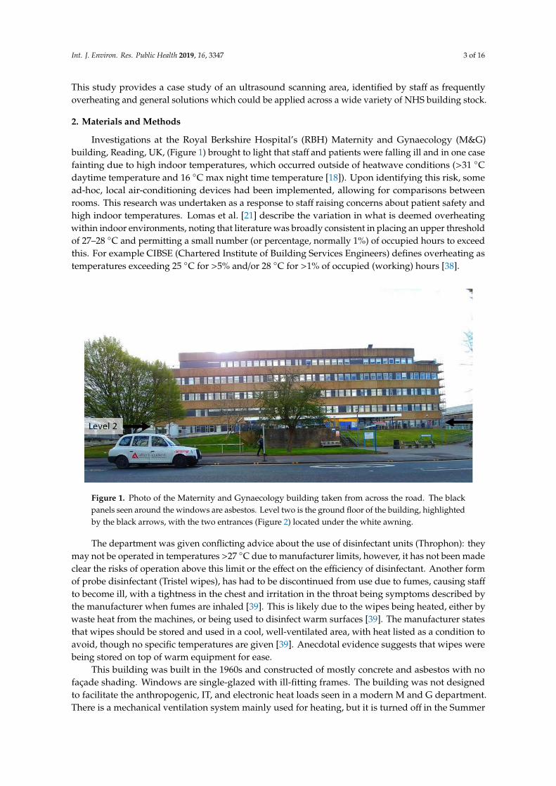
Figure 1. Photo of the Maternity and Gynaecology building taken from across the road. The blackpanels seen around the windows are asbestos. Level two is the ground floor of the building, highlightedby the black arrows, with the two entrances (Figure 2) located under the white awning.
The department was given conflicting advice about the use of disinfectant units (Throphon): theymay not be operated in temperatures >27 ◦C due to manufacturer limits, however, it has not been madeclear the risks of operation above this limit or the effect on the efficiency of disinfectant. Another formof probe disinfectant (Tristel wipes), has had to be discontinued from use due to fumes, causing staff
to become ill, with a tightness in the chest and irritation in the throat being symptoms described bythe manufacturer when fumes are inhaled [39]. This is likely due to the wipes being heated, either bywaste heat from the machines, or being used to disinfect warm surfaces [39]. The manufacturer statesthat wipes should be stored and used in a cool, well-ventilated area, with heat listed as a condition toavoid, though no specific temperatures are given [39]. Anecdotal evidence suggests that wipes werebeing stored on top of warm equipment for ease.
This building was built in the 1960s and constructed of mostly concrete and asbestos with nofaçade shading. Windows are single-glazed with ill-fitting frames. The building was not designedto facilitate the anthropogenic, IT, and electronic heat loads seen in a modern M and G department.There is a mechanical ventilation system mainly used for heating, but it is turned off in the Summer
Int. J. Environ. Res. Public Health 2019, 16, 3347 4 of 16
months for cost-saving unless heatwave conditions are declared, or extreme temperatures are reportedto estates, though there is a delay between reporting and activation.
The focus area of the study was the waiting/reception area (capacity: 20–30 people) and staff
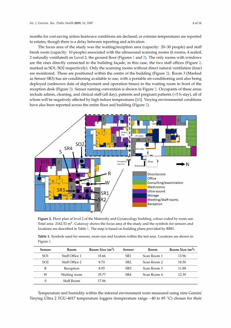
break room (capacity: 10 people) associated with the ultrasound scanning rooms (6 rooms, 4 sealed,2 naturally ventilated) on Level 2, the ground floor (Figures 1 and 2). The only rooms with windowsare the ones directly connected to the building façade, in this case, the two staff offices (Figure 2,marked as SO1, SO2 respectively). Only the scanning rooms without direct natural ventilation (four)are monitored. These are positioned within the centre of the building (Figure 2). Room 3 (Markedas Sensor SR3) has air-conditioning available to use, with a portable air-conditioning unit also beingdeployed (unknown date of deployment and operation times) in the waiting room in front of thereception desk (Figure 2). Sensor naming convention is shown in Figure 2. Occupants of these areasinclude admin, cleaning, and clinical staff (all day), patients and pregnant patients (<5 h stay), all ofwhom will be negatively affected by high indoor temperatures [40]. Varying environmental conditionshave also been reported across the entire floor and building (Figure 2).
Int. J. Environ. Res. Public Health 2019, 16, x 4 of 16
The focus area of the study was the waiting/reception area (capacity: 20–30 people) and staff
break room (capacity: 10 people) associated with the ultrasound scanning rooms (6 rooms, 4 sealed,
2 naturally ventilated) on Level 2, the ground floor (Figures 1, 2). The only rooms with windows are
the ones directly connected to the building façade, in this case, the two staff offices (Figure 2, marked
as SO1, SO2 respectively). Only the scanning rooms without direct natural ventilation (four) are
monitored. These are positioned within the centre of the building (Figure 2). Room 3 (Marked as
Sensor SR3) has air-conditioning available to use, with a portable air-conditioning unit also being
deployed (unknown date of deployment and operation times) in the waiting room in front of the
reception desk (Figure 2). Sensor naming convention is shown in Figure 2. Occupants of these areas
include admin, cleaning, and clinical staff (all day), patients and pregnant patients (<5 h stay), all of
whom will be negatively affected by high indoor temperatures [46]. Varying environmental
conditions have also been reported across the entire floor and building (Figure 2).
Figure 2. Floor plan of level 2 of the Maternity and Gynaecology building, colour coded by room use.
Total area: 2162.52 m2. Cutaway shows the focus area of the study and the symbols for sensors and
locations are described in Table 1. The map is based on building plans provided by RBH.
Temperature and humidity within the internal environment were measured using nine Gemini
Tinytag Ultra 2 TGU-4017 temperature loggers (temperature range −40 to 85 °C) chosen for their
splash-proof case, self-contained design and USB (Universal Serial Bus) connection (Figure 3).
Where possible sensors were positioned out of direct sunlight (only a problem for the Staff Offices,
see Figure 2) and away from windows or any office equipment which may generate waste heat.
Within the waiting room, the sensor was placed in the corner of the room, out of sight, but within the
area where patients sit and wait.
Table 1. Symbols used for sensors, room size and location within the test area. Locations are shown
in Figure 2.
Sensor Room Room Size (m2) Sensor Room Room Size (m2)
SO1 Staff Office 1 18.66 SR1 Scan Room 1 13.96
SO2 Staff Office 2 8.70 SR2 Scan Room 2 18.50
R Reception 8.95 SR3 Scan Room 3 11.88
W Waiting room 35.77 SR4 Scan Room 4 12.39
S Staff Room 17.06
Figure 2. Floor plan of level 2 of the Maternity and Gynaecology building, colour coded by room use.Total area: 2162.52 m2. Cutaway shows the focus area of the study and the symbols for sensors andlocations are described in Table 1. The map is based on building plans provided by RBH.
Table 1. Symbols used for sensors, room size and location within the test area. Locations are shown inFigure 2.
Sensor Room Room Size (m2) Sensor Room Room Size (m2)
SO1 Staff Office 1 18.66 SR1 Scan Room 1 13.96
SO2 Staff Office 2 8.70 SR2 Scan Room 2 18.50
R Reception 8.95 SR3 Scan Room 3 11.88
W Waiting room 35.77 SR4 Scan Room 4 12.39
S Staff Room 17.06
Temperature and humidity within the internal environment were measured using nine GeminiTinytag Ultra 2 TGU-4017 temperature loggers (temperature range −40 to 85 ◦C) chosen for their
Int. J. Environ. Res. Public Health 2019, 16, 3347 5 of 16
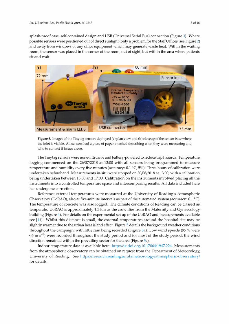
splash-proof case, self-contained design and USB (Universal Serial Bus) connection (Figure 3). Wherepossible sensors were positioned out of direct sunlight (only a problem for the Staff Offices, see Figure 2)and away from windows or any office equipment which may generate waste heat. Within the waitingroom, the sensor was placed in the corner of the room, out of sight, but within the area where patientssit and wait.
Int. J. Environ. Res. Public Health 2019, 16, x 5 of 16
The Tinytag sensors were none-intrusive and battery-powered to reduce trip hazards.
Temperature logging commenced on the 26/07/2018 at 13:00 with all sensors being programmed to
measure temperature and humidity every five minutes (accuracy: 0.1 °C, 5%). Three hours of
calibration were undertaken beforehand. Measurements in-situ were stopped on 30/08/2018 at 13:00,
with a calibration being undertaken between 13:00 and 17:00. Calibration on the instruments
involved placing all the instruments into a controlled temperature space and intercomparing results.
All data included here has undergone correction.
Figure 3. Images of the Tinytag sensors deployed (a) plan view and (b) closeup of the sensor base
where the inlet is visible. All sensors had a piece of paper attached describing what they were
measuring and who to contact if issues arose.
Reference external temperatures were measured at the University of Reading’s Atmospheric
Observatory (UoRAO), also at five-minute intervals as part of the automated system (accuracy: 0.1
°C). The temperature of concrete was also logged. The climate conditions of Reading can be classed
as temperate. UoRAO is approximately 1.5 km as the crow flies from the Maternity and
Gynaecology building (Figure 4). For details on the experimental set up of the UoRAO and
measurements available see [47]. Whilst this distance is small, the external temperatures around the
hospital site may be slightly warmer due to the urban heat island effect. Figure 5 details the
background weather conditions throughout the campaign, with little rain being recorded (Figure
5a). Low wind speeds (95 % were <6 m s–1) were recorded throughout the study period and for most
of the study period, the wind direction remained within the prevailing sector for the area (Figure 5c).
Figure 3. Images of the Tinytag sensors deployed (a) plan view and (b) closeup of the sensor base wherethe inlet is visible. All sensors had a piece of paper attached describing what they were measuring andwho to contact if issues arose.
The Tinytag sensors were none-intrusive and battery-powered to reduce trip hazards. Temperaturelogging commenced on the 26/07/2018 at 13:00 with all sensors being programmed to measuretemperature and humidity every five minutes (accuracy: 0.1 ◦C, 5%). Three hours of calibration wereundertaken beforehand. Measurements in-situ were stopped on 30/08/2018 at 13:00, with a calibrationbeing undertaken between 13:00 and 17:00. Calibration on the instruments involved placing all theinstruments into a controlled temperature space and intercomparing results. All data included herehas undergone correction.
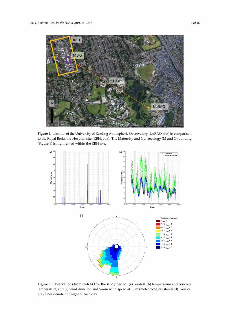
Reference external temperatures were measured at the University of Reading’s AtmosphericObservatory (UoRAO), also at five-minute intervals as part of the automated system (accuracy: 0.1 ◦C).The temperature of concrete was also logged. The climate conditions of Reading can be classed astemperate. UoRAO is approximately 1.5 km as the crow flies from the Maternity and Gynaecologybuilding (Figure 4). For details on the experimental set up of the UoRAO and measurements availablesee [41]. Whilst this distance is small, the external temperatures around the hospital site may beslightly warmer due to the urban heat island effect. Figure 5 details the background weather conditionsthroughout the campaign, with little rain being recorded (Figure 5a). Low wind speeds (95 % were<6 m s–1) were recorded throughout the study period and for most of the study period, the winddirection remained within the prevailing sector for the area (Figure 5c).
Indoor temperature data is available here: http://dx.doi.org/10.17864/1947.224. Measurementsfrom the atmospheric observatory can be obtained on request from the Department of Meteorology,University of Reading. See https://research.reading.ac.uk/meteorology/atmospheric-observatory/
for details.
Int. J. Environ. Res. Public Health 2019, 16, 3347 6 of 16
Int. J. Environ. Res. Public Health 2019, 16, x 6 of 16
Figure 4. Location of the University of Reading Atmospheric Observatory (UoRAO, dot) in
comparison to the Royal Berkshire Hospital site (RBH, box). The Maternity and Gynaecology (M and
G) building (Figure 1) is highlighted within the RBH site.
Figure 5. Observations from UoRAO for the study period. (a) rainfall, (b) temperature and concrete
temperature, and (c) wind direction and 5-min wind speed at 10 m (meteorological standard).
Vertical grey lines denote midnight of each day.
Figure 4. Location of the University of Reading Atmospheric Observatory (UoRAO, dot) in comparisonto the Royal Berkshire Hospital site (RBH, box). The Maternity and Gynaecology (M and G) building(Figure 1) is highlighted within the RBH site.
Int. J. Environ. Res. Public Health 2019, 16, x 6 of 16
Figure 4. Location of the University of Reading Atmospheric Observatory (UoRAO, dot) in
comparison to the Royal Berkshire Hospital site (RBH, box). The Maternity and Gynaecology (M and
G) building (Figure 1) is highlighted within the RBH site.
Figure 5. Observations from UoRAO for the study period. (a) rainfall, (b) temperature and concrete
temperature, and (c) wind direction and 5-min wind speed at 10 m (meteorological standard).
Vertical grey lines denote midnight of each day.
Figure 5. Observations from UoRAO for the study period. (a) rainfall, (b) temperature and concretetemperature, and (c) wind direction and 5-min wind speed at 10 m (meteorological standard). Verticalgrey lines denote midnight of each day.
Int. J. Environ. Res. Public Health 2019, 16, 3347 7 of 16
3. Results
A diurnal cycle is present for all rooms, with more extreme temperatures being seen in the Staff
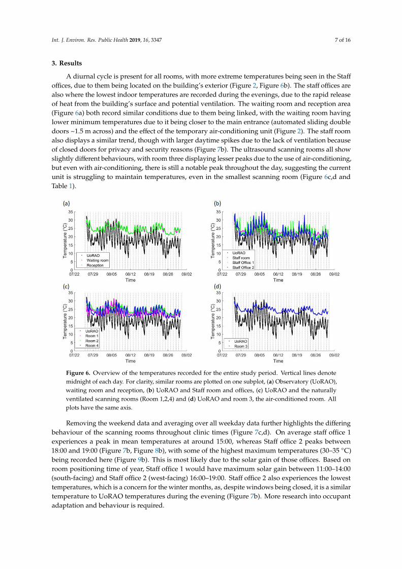
offices, due to them being located on the building’s exterior (Figure 2, Figure 6b). The staff offices arealso where the lowest indoor temperatures are recorded during the evenings, due to the rapid releaseof heat from the building’s surface and potential ventilation. The waiting room and reception area(Figure 6a) both record similar conditions due to them being linked, with the waiting room havinglower minimum temperatures due to it being closer to the main entrance (automated sliding doubledoors ~1.5 m across) and the effect of the temporary air-conditioning unit (Figure 2). The staff roomalso displays a similar trend, though with larger daytime spikes due to the lack of ventilation becauseof closed doors for privacy and security reasons (Figure 7b). The ultrasound scanning rooms all showslightly different behaviours, with room three displaying lesser peaks due to the use of air-conditioning,but even with air-conditioning, there is still a notable peak throughout the day, suggesting the currentunit is struggling to maintain temperatures, even in the smallest scanning room (Figure 6c,d andTable 1).
Int. J. Environ. Res. Public Health 2019, 16, x 7 of 16
Indoor temperature data is available here: http://dx.doi.org/10.17864/1947.224. Measurements
from the atmospheric observatory can be obtained on request from the Department of Meteorology,
University of Reading. See https://research.reading.ac.uk/meteorology/atmospheric-observatory/ for
details.
3. Results
A diurnal cycle is present for all rooms, with more extreme temperatures being seen in the Staff
offices, due to them being located on the building’s exterior (Figure 2, Figure 6b). The staff offices are
also where the lowest indoor temperatures are recorded during the evenings, due to the rapid
release of heat from the building’s surface and potential ventilation. The waiting room and reception
area (Figure 6a) both record similar conditions due to them being linked, with the waiting room
having lower minimum temperatures due to it being closer to the main entrance (automated sliding
double doors ~1.5 m across) and the effect of the temporary air-conditioning unit (Figure 2). The staff
room also displays a similar trend, though with larger daytime spikes due to the lack of ventilation
because of closed doors for privacy and security reasons (Figure 7b). The ultrasound scanning rooms
all show slightly different behaviours, with room three displaying lesser peaks due to the use of
air-conditioning, but even with air-conditioning, there is still a notable peak throughout the day,
suggesting the current unit is struggling to maintain temperatures, even in the smallest scanning
room (Figure 6c,d and Table 1).
Figure 6. Overview of the temperatures recorded for the entire study period. Vertical lines denote
midnight of each day. For clarity, similar rooms are plotted on one subplot, (a) Observatory
(UoRAO), waiting room and reception, (b) UoRAO and Staff room and offices, (c) UoRAO and the
naturally ventilated scanning rooms (Room 1,2,4) and (d) UoRAO and room 3, the air-conditioned
room. All plots have the same axis.
Removing the weekend data and averaging over all weekday data further highlights the
differing behaviour of the scanning rooms throughout clinic times (Figure 7c,d). On average staff
office 1 experiences a peak in mean temperatures at around 15:00, whereas Staff office 2 peaks
between 18:00 and 19:00 (Figure 7b, Figure 8b), with some of the highest maximum temperatures
(30–35 °C) being recorded here (Figure 9b). This is most likely due to the solar gain of those offices.
Based on room positioning time of year, Staff office 1 would have maximum solar gain between
11:00–14:00 (south-facing) and Staff office 2 (west-facing) 16:00–19:00. Staff office 2 also experiences
Figure 6. Overview of the temperatures recorded for the entire study period. Vertical lines denotemidnight of each day. For clarity, similar rooms are plotted on one subplot, (a) Observatory (UoRAO),waiting room and reception, (b) UoRAO and Staff room and offices, (c) UoRAO and the naturallyventilated scanning rooms (Room 1,2,4) and (d) UoRAO and room 3, the air-conditioned room. Allplots have the same axis.
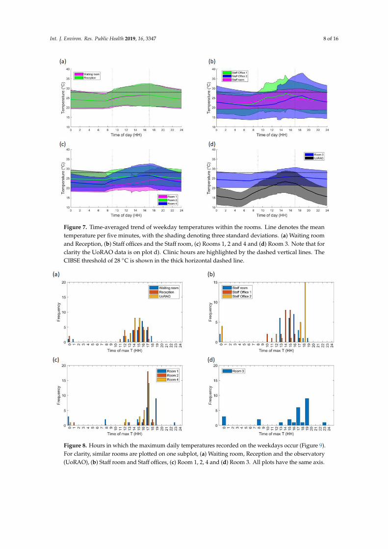
Removing the weekend data and averaging over all weekday data further highlights the differingbehaviour of the scanning rooms throughout clinic times (Figure 7c,d). On average staff office 1experiences a peak in mean temperatures at around 15:00, whereas Staff office 2 peaks between18:00 and 19:00 (Figure 7b, Figure 8b), with some of the highest maximum temperatures (30–35 ◦C)being recorded here (Figure 9b). This is most likely due to the solar gain of those offices. Based onroom positioning time of year, Staff office 1 would have maximum solar gain between 11:00–14:00(south-facing) and Staff office 2 (west-facing) 16:00–19:00. Staff office 2 also experiences the lowesttemperatures, which is a concern for the winter months, as, despite windows being closed, it is a similartemperature to UoRAO temperatures during the evening (Figure 7b). More research into occupantadaptation and behaviour is required.
Int. J. Environ. Res. Public Health 2019, 16, 3347 8 of 16
Int. J. Environ. Res. Public Health 2019, 16, x 8 of 16
the lowest temperatures, which is a concern for the winter months, as, despite windows being
closed, it is a similar temperature to UoRAO temperatures during the evening (Figure 7b). More
research into occupant adaptation and behaviour is required.
The staff room has a peak in temperature at around 14:00, linked to anthropogenically created
heat from lunch breaks between 12:00 and 14:00 (Figure 7b, Figure 8b). The waiting room and
reception areas experience a slow rise in temperature throughout clinic times (Figure 7a), with
maximum temperatures occurring most frequently between 12:00 and 17:00, in part due to the
presence of people (Figure 8a). This rise in temperature is less steep than the scan rooms (Figure 7c)
due to the proximity to the entrance doors, less equipment, and the influence of the portable
air-conditioning unit installed within the waiting area.
A large variation is seen in the daily average temperatures for scanning rooms 1, 2, and 4, with all
tending towards a peak in mean temperatures at 17:00 (Figure 8c), an accumulation of high external
temperatures, waste heat from equipment and anthropogenic heat (Figure 7c). Scan room 3’s mean
temperature is kept fairly constant due to the air-conditioning unit (operated by staff, with heat
extracted to the roof) with its most frequent daily maximum temperatures being 1–2 °C lower than the
other rooms (Figure 9c, d). Differences between rooms 1, 2, and 4 are likely due to differing usage
patterns, size, staff preference, location of different equipment, and differing structure (Figure 2). The
time of the daily maximum temperatures of Scan room 3 is slightly later than the other rooms, due to
the air-conditioning unit being turned off after clinic hours and the room returning to equilibrium
(Figure 8d).
Maximum temperatures occurring around 23:00 to 01:00 h were not due to the heating system,
updating equipment or out-of-hours use of the area. These occurrences mostly occur on a day where
conditions changed from sunny to overcast (e.g., 08/08/2019 after the period with the highest
maximum temperatures, Figure 6 and the peak external temperature dropped significantly, with the
late-night temperature being caused by heat storage, especially if rooms are closed off with little
ventilation.
Figure 7. Time-averaged trend of weekday temperatures within the rooms. Line denotes the mean
temperature per five minutes, with the shading denoting three standard deviations. (a) Waiting
room and Reception, (b) Staff offices and the Staff room, (c) Rooms 1, 2 and 4 and (d) Room 3. Note
that for clarity the UoRAO data is on plot d). Clinic hours are highlighted by the dashed vertical
lines. The CIBSE threshold of 28 °C is shown in the thick horizontal dashed line.
Figure 7. Time-averaged trend of weekday temperatures within the rooms. Line denotes the meantemperature per five minutes, with the shading denoting three standard deviations. (a) Waiting roomand Reception, (b) Staff offices and the Staff room, (c) Rooms 1, 2 and 4 and (d) Room 3. Note that forclarity the UoRAO data is on plot d). Clinic hours are highlighted by the dashed vertical lines. TheCIBSE threshold of 28 ◦C is shown in the thick horizontal dashed line.
Int. J. Environ. Res. Public Health 2019, 16, x 9 of 16
Figure 8. Hours in which the maximum daily temperatures recorded on the weekdays occur (Figure
9). For clarity, similar rooms are plotted on one subplot, (a) Waiting room, Reception and the
observatory (UoRAO), (b) Staff room and Staff offices, (c) Room 1,2, 4 and (d) Room 3. All plots have
the same axis.
Figure 9. Maximum daily temperatures recorded in all rooms across all weekday measurements. For
clarity, similar rooms are plotted on one subplot (a) Waiting room, Reception and the observatory
(UoRAO), (b) Staff room and Staff offices, (c) Room 1,2, 4 and (d) Room 3. All plots have the same
axis. The vertical dashed line denotes an upper threshold of 28 °C.
Focusing just on the scan rooms, the clinics run five days a week from 09:00–17:00 each day and
accounting for bank holidays, this equates to ~20 h out of 2016 clinic hours above 28 °C per year.
Two-hundred-and-twenty-five clinic hours were measured over the course of this study. The results
of the Staff room (S) and Scan room 1 (SR1) suggest that high temperatures within those rooms are
Figure 8. Hours in which the maximum daily temperatures recorded on the weekdays occur (Figure 9).For clarity, similar rooms are plotted on one subplot, (a) Waiting room, Reception and the observatory(UoRAO), (b) Staff room and Staff offices, (c) Room 1, 2, 4 and (d) Room 3. All plots have the same axis.

Int. J. Environ. Res. Public Health 2019, 16, 3347 9 of 16
Int. J. Environ. Res. Public Health 2019, 16, x 9 of 16
Figure 8. Hours in which the maximum daily temperatures recorded on the weekdays occur (Figure
9). For clarity, similar rooms are plotted on one subplot, (a) Waiting room, Reception and the
observatory (UoRAO), (b) Staff room and Staff offices, (c) Room 1,2, 4 and (d) Room 3. All plots have
the same axis.
Figure 9. Maximum daily temperatures recorded in all rooms across all weekday measurements. For
clarity, similar rooms are plotted on one subplot (a) Waiting room, Reception and the observatory
(UoRAO), (b) Staff room and Staff offices, (c) Room 1,2, 4 and (d) Room 3. All plots have the same
axis. The vertical dashed line denotes an upper threshold of 28 °C.
Focusing just on the scan rooms, the clinics run five days a week from 09:00–17:00 each day and
accounting for bank holidays, this equates to ~20 h out of 2016 clinic hours above 28 °C per year.
Two-hundred-and-twenty-five clinic hours were measured over the course of this study. The results
of the Staff room (S) and Scan room 1 (SR1) suggest that high temperatures within those rooms are
Figure 9. Maximum daily temperatures recorded in all rooms across all weekday measurements. Forclarity, similar rooms are plotted on one subplot (a) Waiting room, Reception and the observatory(UoRAO), (b) Staff room and Staff offices, (c) Room 1, 2, 4 and (d) Room 3. All plots have the same axis.The vertical dashed line denotes an upper threshold of 28 ◦C.
The staff room has a peak in temperature at around 14:00, linked to anthropogenically created heatfrom lunch breaks between 12:00 and 14:00 (Figure 7b, Figure 8b). The waiting room and reception areasexperience a slow rise in temperature throughout clinic times (Figure 7a), with maximum temperaturesoccurring most frequently between 12:00 and 17:00, in part due to the presence of people (Figure 8a).This rise in temperature is less steep than the scan rooms (Figure 7c) due to the proximity to theentrance doors, less equipment, and the influence of the portable air-conditioning unit installed withinthe waiting area.
A large variation is seen in the daily average temperatures for scanning rooms 1, 2, and 4, with alltending towards a peak in mean temperatures at 17:00 (Figure 8c), an accumulation of high externaltemperatures, waste heat from equipment and anthropogenic heat (Figure 7c). Scan room 3’s meantemperature is kept fairly constant due to the air-conditioning unit (operated by staff, with heatextracted to the roof) with its most frequent daily maximum temperatures being 1–2 ◦C lower thanthe other rooms (Figure 9c,d). Differences between rooms 1, 2, and 4 are likely due to differing usagepatterns, size, staff preference, location of different equipment, and differing structure (Figure 2). Thetime of the daily maximum temperatures of Scan room 3 is slightly later than the other rooms, dueto the air-conditioning unit being turned off after clinic hours and the room returning to equilibrium(Figure 8d).
Maximum temperatures occurring around 23:00 to 01:00 h were not due to the heating system,updating equipment or out-of-hours use of the area. These occurrences mostly occur on a day whereconditions changed from sunny to overcast (e.g., 08/08/2019 after the period with the highest maximumtemperatures, Figure 6 and the peak external temperature dropped significantly, with the late-nighttemperature being caused by heat storage, especially if rooms are closed off with little ventilation.
Focusing just on the scan rooms, the clinics run five days a week from 09:00–17:00 each day andaccounting for bank holidays, this equates to ~20 h out of 2016 clinic hours above 28 ◦C per year.Two-hundred-and-twenty-five clinic hours were measured over the course of this study. The results ofthe Staff room (S) and Scan room 1 (SR1) suggest that high temperatures within those rooms are notpersistent and may be caused by equipment being appropriately powered down when not in use. The
Int. J. Environ. Res. Public Health 2019, 16, 3347 10 of 16
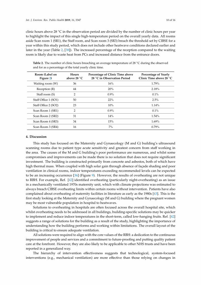
clinic hours above 28 ◦C in the observation period are divided by the number of clinic hours per yearto highlight the impact of this single high-temperature period on the overall yearly data. All roomsaside Scan room 1 (SR1), the Staff room, and Scan room 3 (SR3) breach the threshold set by CIBSE for ayear within this study period, which does not include other heatwave conditions declared earlier andlater in the year (Table 2, [38]). The increased percentage of the reception compared to the waitingroom is likely due to waste heat from PCs and increased distance from the entrance doors.
Table 2. The number of clinic hours breaching an average temperature of 28 ◦C during the observedand for as a percentage of the total yearly clinic time.
Room (Label onFigure 2)
Hoursabove 28 ◦C
Percentage of Clinic Time above28 ◦C in Observation Period
Percentage of YearlyClinic Time above 28 ◦C
Waiting room (W) 36 16% 1.79%
Reception (R) 44 20% 2.18%
Staff room (S) 2 0.9% 0.1%
Staff Office 1 (SO1) 50 22% 2.5%
Staff Office 2 (SO2) 23 10% 1.14%
Scan Room 1 (SR1) 2 0.9% 0.1%
Scan Room 2 (SR2) 31 14% 1.54%
Scan Room 4 (SR3) 34 15% 1.69%
Scan Room 3 (SR4) 16 7% 0.79%
4. Discussion
This study has focused on the Maternity and Gynaecology (M and G) building’s ultrasoundscanning rooms due to patient type acute sensitivity and greatest concern from staff working inthe area. The causes of the M and G building’s poor performance are numerous, and whilst somecompromises and improvements can be made there is no solution that does not require significantinvestment. The building is constructed primarily from concrete and asbestos, both of which havehigh thermal mass. When coupled with high solar gain through absence of façade shading and poorventilation in clinical rooms, indoor temperatures exceeding recommended levels can be expectedto be an increasing occurrence [36] (Figure 9). However, the results of overheating are not uniqueto RBH. For example, Ref. [42] identified overheating (particularly night-overheating) as an issuein a mechanically ventilated 1970s maternity unit, which with climate projections was estimated toalways breach CIBSE overheating limits within certain rooms without intervention. Patients have alsocomplained about overheating of maternity facilities in literature as early as the 1980s [43]. This is thefirst study looking at the Maternity and Gynaecology (M and G) building where the pregnant womenmay be most vulnerable population in hospital to heatwaves.
Solutions to overheating in hospitals are often focused across the overall hospital site, whichwhilst overheating needs to be addressed in all buildings, building-specific solutions may be quickerto implement and reduce indoor temperatures in the short-term, called low-hanging fruits. Ref. [42]suggests a range of solutions for the building as a result of the study, highlighting the importance ofunderstanding how the building performs and working within limitations. The overall layout of thebuilding is critical to ensure adequate ventilation.
All solutions were required to align with the core values of the RBH: a dedication to the continuousimprovement of people and services and a commitment to future-proofing and putting quality patientcare at the forefront. However, they are also likely to be applicable to other NHS trusts and have beenreported in a generalized way.
The hierarchy of intervention effectiveness suggests that technological, system-focusedinterventions (e.g., mechanical ventilation) are more effective than those relying on changes in
Int. J. Environ. Res. Public Health 2019, 16, 3347 11 of 16
human behaviour [44]. However, at a systems level, several limiting factors influence the implicationof solutions, these include but are not limited to budget, patient safety and privacy, complexity,maintenance, hospital reputation, and building limitations. The changing climate must also beconsidered with temperatures in the South-East predicted to rise by 2–4 ◦C by 2039 and 3–5 ◦C by2059 [1]. Ref. [1] also predicts that summers as hot as 2018 will increase in probability from <10% to anestimated 10–25%, meaning that overheating will become more frequent.
Whilst some short-term solutions are suggested within the NHS Royal Berkshire FoundationHospital Trust’s Adverse weather guidelines, these are only triggered once external temperaturerequirements (31 ◦C daytime temperature and 16 ◦C max night time temperature [18]) are met, whereasthe indoor conditions become a risk before these conditions are met. As such, preparation withinthis area should begin at the start of the summer period and remain in place until October for staff
and patient safety. Similar pro-active, rather than reactive behaviour may also be of benefit for otherbuildings and other Trusts [17].
Often the central scanning rooms are closed off for patient privacy, further reducing ventilationfrom doors and nearby windows. The anthropogenic waste heat, odour and CO2 further exacerbatethe problem. For rooms where air-conditioning is in place, doors should remain closed to ensure thatcooling is effective. Waste heat from old bulbs may also contribute, with changing to LED (light-emittingdiode) bulbs a potential solution. Again, these are broadly applicable to similar working environments.
One of the key problems at RBH identified by staff was the centralised control and slow responseof the ventilation systems. Within the M&G building, there are multiple clinics, wards and serviceswhich require different climates. For example, wards are often kept warmer for elderly patients andpremature babies, whereas this may be too warm for clinic patients. Diligent maintenance of existingHVAC systems can also reduce energy wastage, operating costs, and CO2 emissions, a solution not justlimited to the RBH.
Another highlighted problem is the lack of data and evidence about room temperatures, whichprompted the department to buy thermometers for certain rooms. Whilst these instruments maybe cheap and inaccurate, if installed correctly they provide staff with a guideline of when to stopusing temperature-sensitive disinfectants and when to pre-emptively trigger local heatwave measures.Having estates departments deploy measurements in at-risk areas will allow for a greater understandingof the unique problems faced in each hospital area.
4.1. Ventilation and Cooling
Natural ventilation is not a viable solution in this area of the RBH, due to the central positionof the at-risk scanning rooms within the building (Figure 2). Also, within heatwave conditions, it isexpected that air-pollution also increases, adversely affecting those with respiratory conditions [18].Refs. [24,45,46] highlight that there are few examples of innovative natural ventilation/passive coolingstrategies being used in hospital buildings, due to risk-adverse procurement and tight budget constraints.Noise may also prevent windows and doors from being opened. Whilst this study has focused ontemperature, other factors, such as airflow, moisture, and odour also influence thermal comfort andmay also need to be considered for specific patient groups. Other more complex ventilation solutionsare described in [45].
Leaving internal doors open where possible overnight will allow for cooling across the entirebuilding, though security concerns may prevent this. Another option, dependent on clinic demand,is to allow for the rotation of rooms used for scanning throughout the day, to equalise the exposureamongst staff and to ensure that they have some relief from the heat. Rooms not in use can haveequipment switched off to prevent overheating. This solution could be applied NHS wide, as long asthe unique heating patterns of buildings are understood.
The use of desk, standing and ceiling fans may reduce reports of air staleness, a low-energy,low-cost and low intervention approach, these are dependent on health and safety, infection controland also the weight-bearing ability of the ceilings [25]. Temporary cooling is provided by portable air
Int. J. Environ. Res. Public Health 2019, 16, 3347 12 of 16
conditioning units as per the local heatwave plan, but these require a location and maintenance plan toreduce infection risk and ensure waste heat is vented appropriately. Local staff are not instructed onhow to effectively use the units, often rendering them ineffective over time. Portable air-conditioningunits have a limited range, and should be positioned in areas of (a) most need/highest temperatures(e.g., Scan room 3) or (b) where most people will benefit from them (e.g., the waiting area).
A more permanent RBH specific solution would be to build air conditioning units into eachscanning room, as they are effective at maintaining constant cooler temperatures. With traditionalair-conditioning units, a maintenance plan, and a suitable design are essential to ensure that the unitsthemselves are not an infection source due to mould build-up [47,48] and that waste heat is suitablyvented away. Good practice in the maintenance and repair of existing energy services is relatively lowcost and has an important role to play in improving the resilience of buildings [25]. Depending on thebudget chilled beams are also a potential option [49].
Safe storage of Tristel wipes away from heat sources should also be encouraged and enforced, asthese are often stored for convenience on the machines, which give out waste heat, leading to fumesbeing released. Providing specific storage solutions may aid prevent this.
4.2. People
Increasing patient’s awareness of poor conditions within the building if done correctly wouldnot impact on the public opinion on the department. Repeat visitors are likely to take preparatoryaction and adjust their behaviours based on their previous experiences, but for new patients, theuncomfortable conditions may impact on their perception of the service provided [43]. Including awarning of the high temperatures in clinic letters may help. Another option may be to provide moregeneral heatwave coping tips and to remind patients to dress appropriately for the weather, weareasily removable layers and to bring fluids. Again, this could be standardised for the entire hospitaland utilised NHS wide.
When the patients are in the building, easy access to drinking-safe water would aid in ensuringthat patient’s stay hydrated. In this test study, whilst there are shops nearby (Figure 2), it is not possiblefor patients to visit whilst remaining in sight or hearing distance of the waiting area, and it is not clearwhether taps in toilets are safe to drink. Lidded jugs of water or a water machine (pre-existing) arepossibilities. Disposable cups and other consumables should be closely monitored in the risk period,in order to ensure that patients can actually access the water. This should be given as a dedicated roleto a member of staff. An option which does not require extra resource is the installation of a pipedwater-fountain. This is especially important if the waiting time has increased, the waiting area is busyor if the patient is attending a clinic in the afternoon, as these were often when the highest internaltemperatures occurred (Figures 7 and 8). This measure may also encourage staff to stay hydrated asthey benefit from easy access to drinking water. Again, increasing water availability without increasinginfection risk hospital-wide may be of benefit from a health perspective, especially if nationwideguidelines are created to facilitate easy installation.
Identifying the most vulnerable patients and ensuring that their appointments are in the morningmay also reduce heat-risk exposure to those individuals both during their stay and on their journeyto and from the Royal Berkshire Hospital. Another option is to ensure that they are seen in thelower-temperature rooms if possible. Signs instructing patients to inform a member of staff if they feelunwell may encourage patients to seek pre-emptive help. Instructions for staff as to how to rapidlycool patients and how to manage their own heat exposure should also be provided. Again, this couldbe applicable to all hospitals, though the timings of cooler appointments will differ depending onbuilding and location.
Setting up a cool room (<26 ◦C) [18], in line with the actions outlined in the NHS Royal BerkshireHospital Foundation Trust’s Adverse weather guidelines at all times over the summer period will aidin ensuring patient and staff risk is reduced (Level 1 heatwave action in [18]).

Int. J. Environ. Res. Public Health 2019, 16, 3347 13 of 16
Uniforms pose a particular challenge in successfully balancing the needs of adequate infectioncontrol, personal protection and protecting the individual from excess heat gain. Experience fromdepartments such as Special Care Baby Units where high temperatures are the norm may be useful [26].
5. Conclusions
The Maternity and Gynaecology building at the Royal Berkshire Hospital suffers from overheatingissues throughout the year, not just during the summer, with overheating events likely to increasein length and frequency due to climate change [1]. Waiting areas, receptions, and scan rooms allbreached overheating guidelines on indoor temperature limits within the 35-day measurement period.Maximum temperatures occurred during the afternoon, though the timing of these vary depending onroom location, with those exposed experiencing larger peaks related to solar gain at differing timescompared to internal rooms, where temperatures rose quicker due to poor ventilation. The effect ofanthropogenically generated heat is highly significant and should be considered when optimisingpatient flow. The indoor environment and the external environment are not well coupled, especiallyfor the more central rooms with high indoor heat generation, meaning heatwave conditions based onexternal temperatures may not always be relevant, with preventative measures being triggered too late.
The overheating challenges facing the NHS have no single cookie-cutter solution due to the widevariety of building stock. This paper has focused on an area of a single building within one hospitaland has covered solutions from a low hanging fruit level (such as clothing advice in clinic letters andimproved patient access to water) to a hospital site level (improved control of ventilation by estatesservices) with the aim of aiding organisations facing similar over-heating problems. A core issue isa lack of localised information/data for hospitals as knowing when the overheating will occur willenable precautionary measures, such as scheduling the most vulnerable patients (e.g., those who aremost advanced in their pregnancy) at typically cooler times in the morning. However, this solutionsuffers from system-wide problems due to patient data confidentiality issues. Some simple solutionsare summarised here:
• Adjustment of clinic times to cooler periods (in this case the morning) for especiallyvulnerable patients.
• Improved signage and correspondence with patients to encourage dressing suitably (easilyremovable layers) for high temperatures.
• Cycling of used rooms to allow rooms to cool and to ensure that staff have some guaranteed relieffrom poor conditions.
• Procurement of fans to improve air-movement and if possible, cooling equipment.• A thorough maintenance schedule that covers any temporary HVAC equipment brought in
during heatwaves.• Ensure the easy availability of water to staff and patients, with a dedicated staff member ensuring
it is accessible.• Set up a cool-room (<26 ◦C) to provide relief from the heat at all times, not just during
heatwave conditions.
Since this case is only one in an array of similar cases, it is clear from the short measurement periodthat if the RBH Maternity and Gynaecology building is breaching overheating thresholds in 2018 theneven by 2030 this will be endemic on a national level. Whilst air-conditioning units help to lowerthe indoor temperatures, this is in direct contradiction to NHS sustainable initiatives. Localised, lowcarbon solutions may aid in reducing the impact of a changing climate. Future work should considerthe full exposure of individual patients as they make their way to and around the hospital as differingroutes will lead to different exposures. Local air quality, CO2 concentrations and airflow should all beconsidered in conjunction with temperature for a range of hospital buildings and patient types.
Int. J. Environ. Res. Public Health 2019, 16, 3347 14 of 16
Author Contributions: Conceptualization, H.G. and Z.L.; Investigation, H.G., S.F.-M., and M.-F.K.; Methodology,H.G. and S.F.-M.; Resources, S.F.-M.; Supervision, Z.L.; Visualization, H.G. and M.-F.K.; Writing—original draft,H.G.; Writing—review & editing, S.F.-M., M.-F.K., and Z.L.
Funding: This work was supported by the EPSRC REFRESH project, Grant number: EP/K021893/1.
Acknowledgments: Thanks go to the Department of Meteorology at the University of Reading for allowing theuse of the Atmospheric Observatory data and to the staff at the Royal Berkshire Hospital that facilitated this workand shared their opinions and knowledge. Thanks to Professor Janet Barlow (University of Reading) for loanof sensors.
Conflicts of Interest: The authors declare no conflict of interest.
References
1. Lowe, J.A.; Bernie, D.; Bett, P.; Bricheno, L.; Brown, S.; Calvert, D.; Clark, R.; Eagle, K.; Edwards, T.; Fosser, G.;et al. UKCP18 Science Overview Report; Met Office Hadley Centre: Exeter, UK, 2018.
2. Seppanen, O.; Fisk, W.J.; Lei, Q.H. Ventilation and performance in office work. Indoor Air 2006, 18, 28–36.[CrossRef] [PubMed]
3. Pilcher, J.J.; Nadler, E.; Busch, C. Effects of hot and cold temperature exposure on performance: A meta-analyticreview. Ergonomics 2002, 45, 682–698. [CrossRef] [PubMed]
4. Hancock, P.A.; Vasmatzidis, I. Effects of heat stress on cognitive performance: The current state of knowledge.Int. J. Hyperth. 2003, 19, 355–372. [CrossRef] [PubMed]
5. Hancock, P.A.; Ross, J.M.; Szalma, J.L. A Meta-Analysis of Performance Response Under Thermal Stressors.Hum. Factors 2007, 49, 851–877. [CrossRef] [PubMed]
6. Jensen, K.L.; Toftum, J.; Friis-Hansen, P. A Bayesian Network approach to the evaluation of building designand its consequences for employee performance and operational costs. Build. Environ. 2009, 44, 456–462.[CrossRef]
7. Roelofsen, P. A computer model for the assessment of employee performance loss as a function of thermaldiscomfort or degree of heat stress. Intell. Build. Int. 2016, 8, 195–214. [CrossRef]
8. Tham, K.W.; Willem, H.C. Room air temperature affects occupants’ physiology, perceptions and mentalalertness. Build. Environ. 2010, 45, 40–44. [CrossRef]
9. Cui, W.; Cao, G.; Park, J.H.; Ouyang, Q.; Zhu, Y. Influence of indoor air temperature on human thermalcomfort, motivation and performance. Build. Environ. 2013, 68, 114–122. [CrossRef]
10. McInnes, J.A.; MacFarlane, E.M.; Sim, M.R.; Smith, P. The impact of sustained hot weather on risk of acutework-related injury in Melbourne, Australia. Int. J. Biometeorol. 2018, 62, 153–163. [CrossRef]
11. Adam-Poupart, A.; Smargiassi, A.; Busque, M.A.; Duguay, P.; Fournier, M.; Zayed, J.; Labrèche, F. Effect ofsummer outdoor temperatures on work-related injuries in Quebec (Canada). Occup. Environ. Med. 2015, 72,338–345. [CrossRef]
12. McInnes, J.A.; Akram, M.; Macfarlane, E.M.; Keegel, T.; Sim, M.R.; Smith, P. Association between highambient temperature and acute work-related injury: A case-crossover analysis using workers’ compensationclaims data. Scand. J. Work Environ. Health 2017, 43, 86–94. [CrossRef] [PubMed]
13. Basagaña, X. High ambient temperatures and work-related injuries. Occup. Environ. Med. 2014, 71, 231.[CrossRef] [PubMed]
14. Xiang, J.; Bi, P.; Pisaniello, D.; Hansen, A. Health Impacts of Workplace Heat Exposure: An EpidemiologicalReview. Ind. Health 2014, 52, 91–101. [CrossRef] [PubMed]
15. Garzon-Villalba, X.P.; Mbah, A.; Wu, Y.; Hiles, M.; Moore, H.; Schwartz, S.W.; Bernard, T.E. Exertional heatillness and acute injury related to ambient wet bulb globe temperature. Am. J. Ind. Med. 2016, 59, 1169–1176.[CrossRef] [PubMed]
16. Kjellstrom, T.; Holmer, I.; Lemke, B. Workplace heat stress, health and productivity—An increasing challengefor low and middle-income countries during climate change. Glob. Health Action 2009, 2. [CrossRef][PubMed]
17. Ibrahim, J.E.; McInnes, J.A.; Andrianopoulos, N.; Evans, S. Minimising harm from heatwaves: A survey ofawareness, knowledge, and practices of health professionals and care providers in Victoria, Australia. Int. J.Public Health 2012, 57, 297–304. [CrossRef] [PubMed]
Int. J. Environ. Res. Public Health 2019, 16, 3347 15 of 16
18. Public Health England. Heatwave Plan for England. Protecting Health and Reducing Harm from Severe Heat andHeatwaves; Public Health England: London, UK, 2018.
19. CCC (Committee on Climate Change). Managing Climate Risks to Well-Being and the Economy: ASC ProgressReport 2014; CCC: London, UK, 2014.
20. Fifield, L.J.; Lomas, K.J.; Giridharan, R.; Allinson, D. Hospital wards and modular construction: Summertimeoverheating and energy efficiency. Build. Environ. 2018, 141, 28–44. [CrossRef]
21. Lomas, K.; Giridharan, R.; Short, C.; Fair, A. Resilience of ‘Nightingale’ hospital wards in a changing climate.Build. Serv. Eng. Res. Technol. 2012, 33, 81–103. [CrossRef]
22. Iddon, C.R.; Mills, T.C.; Giridharan, R.; Lomas, K.J. The influence of hospital ward design on resilience toheat waves: An exploration using distributed lag models. Energy Build. 2015, 86, 573–588. [CrossRef]
23. Kravchenko, J.; Abernethy, A.P.; Fawzy, M.; Lyerly, H.K. Minimization of heatwave morbidity and mortality.Am. J. Prev. Med. 2013, 44, 274–282. [CrossRef]
24. Short, C.A.; Lomas, K.J.; Giridharan, R.; Fair, A.J. Building resilience to overheating into 1960′s UK hospitalbuildings within the constraint of the national carbon reduction target: Adaptive strategies. Build. Environ.2012, 55, 73–95. [CrossRef]
25. Lomas, K.J.; Giridharan, R. Thermal comfort standards, measured internal temperatures and thermalresilience to climate change of free-running buildings: A case-study of hospital wards. Build. Environ. 2012,55, 57–72. [CrossRef]
26. Carmichael, C.; Bickler, G.; Kovats, S.; Pencheon, D.; Murray, V.; West, C.; Doyle, Y. Overheating andHospitals—What do we know? J. Hosp. Adm. 2012, 2, 1. [CrossRef]
27. Honda, H.; Iwata, K. Personal protective equipment and improving compliance among healthcare workersin high-risk settings. Curr. Opin. Infect. Dis. 2016, 29, 400–406. [CrossRef] [PubMed]
28. Shenal, B.V.; Radonovich, L.J.; Cheng, J.; Hodgson, M.; Bender, B.S. Discomfort and exertion associated withprolonged wear of respiratory protection in a health care setting. J. Occup. Environ. Hyg. 2012, 9, 59–64.[CrossRef] [PubMed]
29. Khodakarami, J.; Nasrollahi, N. Thermal comfort in hospitals—A literature review. Renew. Sustain. Energy Rev.2012, 16, 4071–4077. [CrossRef]
30. Qian, H.; Li, Y.; Seto, W.H.; Ching, P.; Ching, W.H.; Sun, H.Q. Natural ventilation for reducing airborneinfection in hospitals. Build. Environ. 2010, 45, 559–565. [CrossRef]
31. Skoog, J.; Fransson, N.; Jagemar, L. Thermal environment in Swedish hospitals: Summer and wintermeasurements. Energy Build. 2005, 37, 872–877. [CrossRef]
32. Adamu, Z.A.; Price, A.D.F.; Cook, M.J. Performance evaluation of natural ventilation strategies for hospitalwards—A case study of Great Ormond Street Hospital. Build. Environ. 2012, 56, 211–222. [CrossRef]
33. King, M.F.; Gough, H.L.; Halios, C.; Barlow, J.F.; Robertson, A.; Hoxey, R.; Noakes, C.J. Investigating theinfluence of neighbouring structures on natural ventilation potential of a full-scale cubical building usingtime-dependent CFD. J. Wind Eng. Ind. Aerodyn. 2017, 169, 265–279. [CrossRef]
34. Gough, H.L.; Luo, Z.; Halios, C.H.; King, M.F.; Noakes, C.J.; Grimmond, C.S.B.; Barlow, J.F.; Hoxey, R.;Quinn, A.D. Field measurement of natural ventilation rate in an idealised full-scale building located in astaggered urban array: Comparison between tracer gas and pressure-based methods. Build. Environ. 2018,137, 246–256. [CrossRef]
35. Giridharan, R.; Lomas, K.J.; Short, C.A.; Fair, A.J. Performance of hospital spaces in summer: A case study ofa ‘Nucleus’-type hospital in the UK Midlands. Energy Build. 2013, 66, 315–328. [CrossRef]
36. Short, C.A.; Al-Maiyah, S. Design strategy for low-energy ventilation and cooling of hospitals. Build. Res. Inf.2009, 37, 264–292. [CrossRef]
37. Mills, G.R.W.; Deka, L.; Price, A.D.F.; Rich-Mahadkar, S.; Pantzartzis, E.; Sellars, P. Critical infrastructurerisk in NHS England: Predicting the impact of building portfolio age. Int. J. Strateg. Prop. Manag. 2015, 19,159–172. [CrossRef]
38. CIBSE (Chartered Institute of Building Services Engineers). TM 52: The Limits of Thermal Comfort: AvoidingOverheating in European Building; CIBSE: London, UK, 2013.
39. Tristel. Tristel Safety Data Sheet; Tristel Solutions Ltd.: Cambridge, UK, 2015.40. Hames, D.; Vardoulakis, S. Climate Change Risk Assessment for the Health Sector. UK 2012 Climate Change Risk
Assessment; Crown: London, UK, 2012.
Int. J. Environ. Res. Public Health 2019, 16, 3347 16 of 16
41. Brugge, R.; Bert, S. One Hundred Years of Reading Weather, 1st ed.; Climatological Observers Link: Berkshire,UK, 2015; ISBN 0956948510.
42. Short, C.A.; Renganathan, G.; Lomas, K.J. A medium-rise 1970s maternity hospital in the east of England:Resilience and adaptation to climate change. Build. Serv. Eng. Res. Technol. 2015, 36, 247–274. [CrossRef]
43. Field, P.A. Parents’ reactions to maternity care. Midwifery 1985, 1, 37–46. [CrossRef]44. Coulter, A.; Ellins, J. Patient-Focused Interventions: A Review of the Evidence; Health Foundation: London, UK,
2006; Volume 1.45. Short, C.A.; Lomas, K.J.; Woods, A. Design strategy for low-energy ventilation and cooling within an urban
heat island. Build. Res. Inf. 2004, 32, 187–206. [CrossRef]46. Lomas, K.J.; Ji, Y. Resilience of naturally ventilated buildings to climate change: advanced natural ventilation
and hospital wards. Energy Build. 2009, 41, 629–653. [CrossRef]47. Parat, S.; Fricker-Hidalgo, H.; Perdrix, A.; Bemer, D.; Pelissier, N.; Grillot, R. Airborne fungal contamination
in air-conditioning systems: Effect of filtering and humidifying devices. Am. Ind. Hyg. Assoc. J. 1996, 57,996–1001. [CrossRef]
48. Mendell, M.J.; Lei-Gomez, Q.; Mirer, A.; Seppanen, O.; Brunner, G. Risk Factors in Heating, Ventilating, andAir-Conditioning Systemsfor Occupant Symptoms in U.S. Office Buildings: The EPA BASE Study; LawrenceBerkeley National Laboratory: Berkeley, CA, USA, 2006.
49. Department of Health. Heating and Ventilation Systems Health Technical Memorandum 03-01: SpecialisedVentilation for Healthcare Premises—Part A: Design and Validation; The Stationery Office: London, UK, 2007.
© 2019 by the authors. Licensee MDPI, Basel, Switzerland. This article is an open accessarticle distributed under the terms and conditions of the Creative Commons Attribution(CC BY) license (http://creativecommons.org/licenses/by/4.0/).