Embed Size (px)
Citation preview

NOTICE DE MONTAGE ET D’UTILISATION
ASSEMBLY USER’S MANUAL AND OPERATING INSTRUCTIONS
4100506 C Notice 75 Tx / Rx V2.2 1

Ι ) RECOMMANDATIONS DE SECURITE
SAFETY RECOMMENDATIONS Les règles d’installation et de sécurité à respecter sont décrites dans les normes relatives aux installations de systèmes de distribution par câbles destinés aux signaux de télévision et services multimédias interactifs disponibles auprès de l’ UTE. ( EN 50083-1 ; UTE C 90122 ; UTE C 90124 ; UTE C 90125). Toute installation doit être en conformité avec les règles définies dans ces normes. Safety and installation rules are given in standards regarding cabled distribution systems for television and interactive multimedia signals EN 50083-1. The installer must follow these rules to be in conformity with the law.. Always implement regulations as issued by national and local authorities.
1- ATTENTION : l’antenne représente près de 0.5m2 de prise au vent ! EVITER L’INSTALLATION LES JOURS DE VENT (même modéré) ! ATTACHER L’ANTENNE si le lieu d’installation est dangereux pour l’installateur ou pour autrui. NE PAS CHERCHER A RETENIR L’ANTENNE en cas de situation critique. CAUTION : This antenna is almost 0.5 square meter wind pressure equivalent area ! DO NOT MAKE AN INSTALLATION IN BAD WEATHER CONDITIONS ! TRY TO FIX IT in case there is potential danger for people. DON’T TRY TO KEEP IT IN YOUR HANDS in critical situation. 2- LIGNES ELECTRIQUES : Repérer les lignes électriques . Ne pas installer l’antenne à moins de 6 mètres d’une telle ligne ! En cas de fondations, consulter les autorités locales pour connaître les réseaux souterrains éventuels. POWER LINES : For safety reasons, watch around to see if you are near to any power line. Make sure a minimum distance of 6 meters (20 feets) separates the antenna from any power line !
Before digging, in case of need for a penetrating antenna mast, contact your local authority to check for any underground cables and (power) utility line(s) information .
3- DIMENSIONNEMENT DES FIXATIONS :
MOUNTING POLE DIMENSIONS: Pour le dimensionnement des fixations , prendre en compte les efforts ci après. Mechanical forces to be considered are shown in the picture below :
4100506 C Notice 75 Tx / Rx V2.2 2

Le diamètre minimum du tube de fixation doit être de 60mm. Minimum pole diameter must be 60 mm. 4- MISE A LA TERRE DE L’INSTALLATION :
GROUNDING : Le mât de fixation de l’antenne et l’équipement de réception doivent être mis à la terre selon la norme EN 50280.
The antenna mast and Ku-band transceiver must be grounded as per EN 50280 standard recommendations.
ΙΙ ) SELECTION DU SITE D’INSTALLATION
SITE SELECTION L’ orientation doit être dégagée dans la direction du satellite considéré : Sud dégagé dans l’hémisphère nord Nord dégagé dans l’hémisphère sud Dans certains pays, une autorisation ou un permis de construire sont nécessaires préalablement à l’installation d’une antenne parabolique. For receiving / transmitting through geostationary satellites, you need a clear view when pointed towards the satellite, that is to say : Clear to the south (in northern hemisphere). Clear to the north (in southern hemisphere). In some countries, an authorisation can be needed for satellite dish installation. Call your local authorities in case of doubt.
ΙΙΙ) OUTILLAGE NECESSAIRE A L’INSTALLATION (non fourni) ASSEMBLY TOOLS REQUIRED FOR INSTALLATION (not supplied)
- boussole - Compass - niveau - Inclinometer - clef de 13 mm (2) - 13 mm nut driver (2) - tournevis plat large - Flat screwdriver (large) - tournevis Posidrive - Posidrive screwdriver (medium) - mesureur de champs professionnel - Professional field strenght meter - cable RF - RF cable - connecteurs - Connectors
4100506 C Notice 75 Tx / Rx V2.2 3

ΙV ) LISTE DES PIECES COMPOSANT L’ANTENNE ANTENNA PARTS LIST
V ) ETAPES D’ASSEMBLAGE STEP BY STEP ASSEMBLY
Voir illustrations page 9~14 / See pictures on pages 9~14
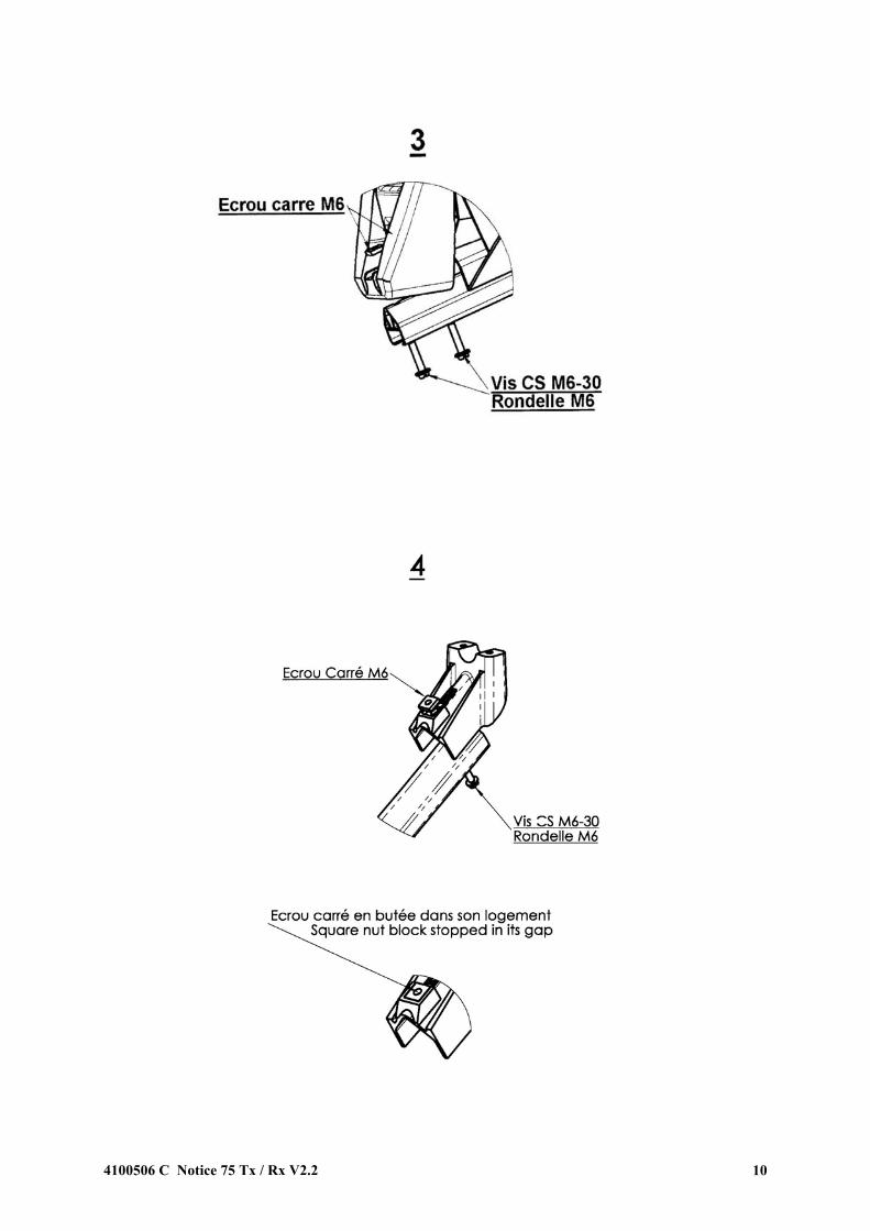
ETAPES DE MONTAGE / ASSEMBLY STEPS 1 - Poser le réflecteur à plat et fixer la monture (4) en utilisant (Vis HM 8-16 avec rondelle L8 × 2; Vis HM 8-
20 et rondelle L8 × 2) .
Place the reflector with the front down and fix the pre-assembled mount (4) using (Screw HM 8 –16 with washers L8 × 2 and Screw HM 8×20 and washers L8 × 2) . 2 - Installer la monture Az-El équipée du réflecteur sur le mât préalablement solidement fixé et serrer l’ensemble légèrement. Install Az-El mount on ground (or wall) pole and tighten the bolts only lightly . 3 - Introduire le bras en profilé aluminium (2) dans son logement et le fixer (2x Vis M6-30, rondelle L6, tuile). Install the aluminium support arm (2) in the gap and fix it. (2x Screw M6-30, washer L6, nut) 4 - Présenter et fixer le berceau support de source (3). L’écrou carré doit être centré dans son logement. Install feed support (3) and fix it. Square nut must be centred in it’s socket.
4100506 C Notice 75 Tx / Rx V2.2 4

5 - Choix de la polarisation et installation du transceiver (ci necessaire): Cette antenne est équipée d’une source compensée .
La sélection de polarisation se fait fonction du positionnement de l ‘OMT par rapport à la source qui est toujours dans la même position devant le réflecteur.
- Selon la polarisation voulue en Rx et Tx, assembler la source et l’OMT en respectant
scrupuleusement les positions des trous de fixation à utiliser. (La polarisation Rx est toujours inverse de Tx et vice versa).
- Positionner l’ensemble sur son support à l’aide des 2 vis M6-30.
Polarisation setting and transceiver installation (when needed): This antenna is equipped with a compensated feed horn. The polarisation setting is made by choosing the orientation of the OMT relative to the feed. The feed itself is always in a fixed position towards the reflector. - According to the wanted polarisation in Rx and Tx, fix the feed and OMT together taking care that
the round waveguides are very well aligned. (Due to the OMT the Rx polarisation is always perpendicular to the Tx polarisation).
- Install the complete unit on the feed bracket of the antenna using the 2 M6-30 screws. L’antenne est maintenant prête à être pointée sur le satellite désiré. The antenna is now ready to be aligned.
VΙ) POINTAGE DE L’ANTENNE (pages 12~18) ANTENNA ALIGNMENT PROCEDURE (pages 12~18)
Le pointage d’une antenne d’émission / réception requiert une grande précision. L’utilisation d’un mesureur de champs professionnel est nécessaire pour parfaire les réglages. Les cartes jointes d’azimut, élévation et polarisation sont utiles pour le réglage initial grossier. Elles sont fonction de la latitude du lieu d’installation et Delta L, écart entre longitude du lieu d’installation et longitude du satellite. Les angles d’azimut et de polarisation sont donnés selon la convention de représentation décrite dans les paramètres de pointage. The receive / transmit antenna alignment procedure requires you to perform this work very precisely. The antenna alignment is done using the received signal only, so it is necessary to do the final adjustments with a professional field strength meter allowing for fine azimuth, polarisation and elevation adjustments. The charts for elevation, azimut and feed polarisation shown on the next pages are given for the initial adjustment, with respect to Earth station latitude and Delta L, difference between earth station longitude and satellite longitude. Angle representation is given according to the convention described in the pointing data. 1- Polarisation du signal reçu : Le réglage de l’antenne se fait en utilisant le signal reçu.
La sélection de polarisation doit donc être effectuée avant l’assemblage du transceiver sur l’antenne , voir figure 5 page 11.
Received signal polarisation : The antenna alignment is done using the received signal.
The polarisation selection must be done before installing the transceiver on the antenna, as shown in figure 5 on page 11.
4100506 C Notice 75 Tx / Rx V2.2 5

2- Elevation de l’antenne voir carte « Elévation » page 16 : Elevation adjustment see Elevation chart page 16 : Déterminer l’élévation selon le lieu d’installation et la position du satellite en utilisant la carte 1 page 16 et afficher cette élévation sur la monture. Débloquer légèrement les écrous A et B
En actionnant la vis F, amener la graduation correspondant à l’élévation recherchée face au centre de l’écrou B puis resserrer modérément les 4 écrous A et B comme indiqué Fig 6.
Use the elevation chart on page 16 to determine your elevation setting according to your geographical location.
Slightly unlock the screws A and B. Actuate screw F in order to move the antenna elevation upwards so that one reaches the elevation marking as indicated by the center of the nut B and tighten the 4 screws as shown in figure 6.
3- Azimut de l’antenne : Antenna azimut adjustment : A ce stade, connecter votre mesureur de champ au LNB de l’ensemble émission / réception.
- Débloquer les écrous C1 (bride inférieure) et C2 (bride supérieure) pour faire tourner l’ensemble autour du mât.
- Déterminer l’angle d’azimut en utilisant les carte d’Azimut page 17 & 18.
Le résultat, pour être précis doit être corrigé de la déviation magnétique du lieu de réception si vous utilisez une boussole.
- Orienter l’antenne dans la direction obtenue à l’aide d’une boussole. Balayer en azimut jusqu’à obtenir le signal voulu et modifier au besoin l’élévation pour obtenir le maximum de signal puis serrer les écrous C1 uniquement. Si le signal est introuvable, augmenter et / ou diminuer l’élévation et recommencer l’opération.
At this point, connect the field strength meter to the LNB output using the correct LNB power supply settings. - Unlock the 4 screws C1 (lower clamp) and C2 (higher clamp) in order to move in azimut the whole
antenna around the mounting pipe.
- Determine the azimut setting using the Azimut charts on page 17 & 18. For a precise pre-setting when using a compass, the azimuth result from the charts must be corrected with your local magnectic deviation.
- Rotate the antenna in the wanted direction using compass reading. Slowly sweep the antenna in azimuth back and forth with several degrees to find the wanted signal. When the signal is detected optimise the coarse azimuth and elevation to get the maximum signal level. Tighten the screws C1 only.
- In case the signal is not found, increase or decrease elevation settings and sweep the azimut again.
4100506 C Notice 75 Tx / Rx V2.2 6

4- Réglages fins (azimut, élévation et polarisation) : Fine tuning for azimut, elevation and polarisation.
Finir les réglages de pointage en utilisant les réglages fins d’azimut et d’élévation, en alternant les réglages jusqu’à ne plus détecter d’amélioration du niveau de signal.
Ces réglages sont accessibles sur la monture Az / El comme le montre la Figure 6. Réglage fin en azimut :
- Laisser légèrement desserés les 2 écrous C2 (bride supérieure).. - Desserrer les 4 écrous D. - Actionner la vis E (visser ou dévisser selon le sens désiré) pour tourner l’antenne vers la droite ou
la gauche jusqu’à obtention du meilleur signal. - Resserrer fermement les 2 écrous C2. - Resserrer les 5 écrous D.
Réglage fin en élévation :
- Desserrer légèrement les 4 écrous A et B. - Actionner la vis F (visser ou dévisser) pour modifier l’élévation vers le haut ou vers le bas. - Resserer les 4 écrous A et B.
Réglage fin de polarisation :
- Consulter la carte des angles de polarisation page 16 afin de noter le sens et la valeur approchée
de l’angle. - Débloquer légèrement les 4 vis G et procéder selon la Fig 7. - Tourner doucement l’ antenne sur elle même, vers la droite ou la gauche avec contrôle du signal
reçu sur le mesureur de champ en mode spectre jusqu’à obtenir le minimum de signal en polarisation inverse.
Une fois ces réglages effectués, serrer toutes les vis de réglages fermement pour éviter tout dépointage du au vent.
En cas d’angle de polarisation supérieur à 22.5° ou inférieur à –22.5°, il est nécessaire de repositionner l’ensemble réflecteur sur la monture, voir instructions étape 8 page 14.
To complete the antenna alignment procedure, you need to, alternatingly, fine adjust the Azimut and Elevation setting in order to reach the maximum signal level. For this purpose, use the fine adjustment systems as described in figure 6.
Azimut fine adjustment :
- Make sure the 2 nuts C2 are not tightened (upper clamp). - Unlock the 4 nuts D. - Actuate the screw E (screw or unscrew according to the wanted direction) in order to move the
antenna left or right and get the maximum signal strenght. - Lock firmly the 2 nuts C2. - Lock firmly the 5 nuts D.
Elevation fine adjustment :
- Slightly unlock the 4 nuts A and B. - Actuate the screw F (screw or unscrew according to the wanted direction) to change the elevation
setting and get the maximum signal strenght. - Lock the 4 nuts A and B.
Polarization fine adjustment :
Polarisation fine adjustment must be achieved using a field-strenght meter in spectrum mode, e.g. with an instrument like a Pro-Link 3.
- Use the polarization chart on page 16 to find the angle sense and approximate value.
4100506 C Notice 75 Tx / Rx V2.2 7

- Slightly unlock the 4 screws G according to figure 7.
- Rotate slowly the antenna until a known signal in the reverse polarisation reaches a minimum level.
Finally, check that all bolts and nuts are correctly tightned to avoid mispointing due to strong winds.
In case of a polarisation angle more than +22.5° or less than –22.5°, it’s necessary to mount the reflector assembly on the mount in a different way as explained in step 8 on page 14.
Sens de l’angle de polarisation Polarization sign
Hémisphère Nord Northern Hemisphere
Hémisphère Sud Southern Hemisphere
Longitude satellite à l’Est du site Satellite longitude East of site + -
Longitude satellite à l’Ouest du site Satellite longitude West of site - +
4100506 C Notice 75 Tx / Rx V2.2 8

ILLUSTRATIONS DES ETAPES D’ASSEMBLAGE
ASSEMBLY STEP BY STEP PICTURES
4100506 C Notice 75 Tx / Rx V2.2 9
4100506 C Notice 75 Tx / Rx V2.2 10

4100506 C Notice 75 Tx / Rx V2.2 11

4100506 C Notice 75 Tx / Rx V2.2 12

Sens de l’angle de polarisation Polarization sign
Hémisphère Nord Northern Hemisphere
Hémisphère Sud Southern Hemisphere
Longitude satellite à l’Est du site Satellite longitude East of site + -
Longitude satellite à l’Ouest du site Satellite longitude West of site - +
4100506 C Notice 75 Tx / Rx V2.2 13
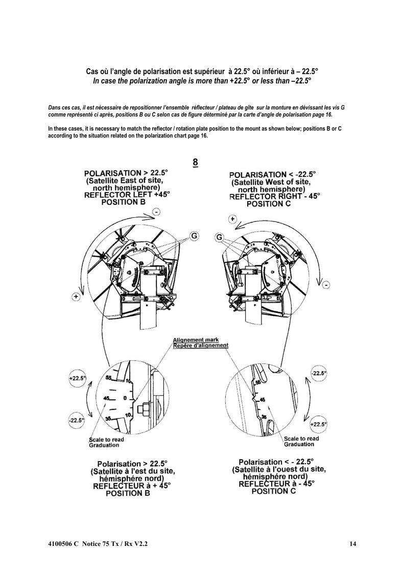
Cas où l’angle de polarisation est supérieur à 22.5° où inférieur à – 22.5° In case the polarization angle is more than +22.5° or less than –22.5°
Dans ces cas, il est nécessaire de repositionner l’ensemble réflecteur / plateau de gîte sur la monture en dévissant les vis G comme représenté ci après, positions B ou C selon cas de figure déterminé par la carte d’angle de polarisation page 16. In these cases, it is necessary to match the reflector / rotation plate position to the mount as shown below; positions B or C according to the situation related on the polarization chart page 16.
4100506 C Notice 75 Tx / Rx V2.2 14

VΙΙ) Données de pointage en fonction de la situation géographique
Pointing data according to geographical situation ATTENTION ! CAUTION ! Longitude Est : Signe positif Longitude Ouest : Signe négatif East longitude : + Sign West longitude : - Sign DELTA représente la Longitude du site d’installation moins la longitude du Satellite en valeur absolue : DELTA is the relative difference between the antenna site longitude and the satellite longitude, in absolute value.
DELTA = Site longitude – Satellite longitude Convention relative aux indications d’angles d’azimut : Azimut chart angles convention : L’angle d’azimut est compté positivement à partir du pôle Nord Azimut angle is positive from North pole
4100506 C Notice 75 Tx / Rx V2.2 15

Carte des angles d’élévation
Elevation chart
Elevation = f(latitude,Delta)
0,0
10,0
20,0
30,0
40,0
50,0
60,0
70,0
80,0
90,0
0,0 10,0 20,0 30,0 40,0 50,0 60,0 70,0 80,0 90,0
latitude
Elev
atio
n
Delta = 0°Delta = 5°Delta = 10°Delta = 15°Delta = 20°Delta = 25°Delta = 30°Delta = 40°Delta = 50°Delta = 60°Delta = 70°
Carte des angles de polarisation
Polarisation chart
Polarization = f( Elevation, Delta)
0,0
10,0
20,0
30,0
40,0
50,0
60,0
70,0
80,0
90,0
100,0
0,0 10,0 20,0 30,0 40,0 50,0 60,0 70,0 80,0 90,0
Latitude (North or South hemisphere)
pola
rizat
ion
Delta = 0°Delta = 5°Delta = 10°Delta = 15°Delta = 20°Delta = 25°Delta = 30°Delta = 40°Delta = 50°Delta = 60°Delta = 70°
4100506 C Notice 75 Tx / Rx V2.2 16

AZIMUT , satellite à l’ouest / site, Hémisphère Nord Azimut chart, satellite west from antenna site, Northern Hemisphere
Azimut = f(latitude,Delta) sat West of site NH
170,0
180,0
190,0
200,0
210,0
220,0
230,0
240,0
250,0
260,0
270,0
280,0
0 10 20 30 40 50 60 70 80 90
Latitude
Azi
mut
Delta = 0°Delta = 5°Delta = 10°Delta = 15°Delta = 20°Delta = 25°Delta = 30°Delta = 40°Delta = 50°Delta = 60°Delta = 70°Delta = 80°
AZIMUT, satellite à l’est / site ; Hémisphère Nord
Azimut chart, satellite east from antenna site, Northern Hemisphere
Azimut = f( latitude, Delta) sat East of site NH
80,0
90,0
100,0
110,0
120,0
130,0
140,0
150,0
160,0
170,0
180,0
190,0
0 10 20 30 40 50 60 70 80 90
latitude station
Azi
mut
Delta = 0°Delta = 5°Delta = 10°Delta = 15°Delta = 20°Delta = 25°Delta = 30°Delta = 40°Delta = 50°Delta = 60°Delta = 70°Delta = 80°
4100506 C Notice 75 Tx / Rx V2.2 17
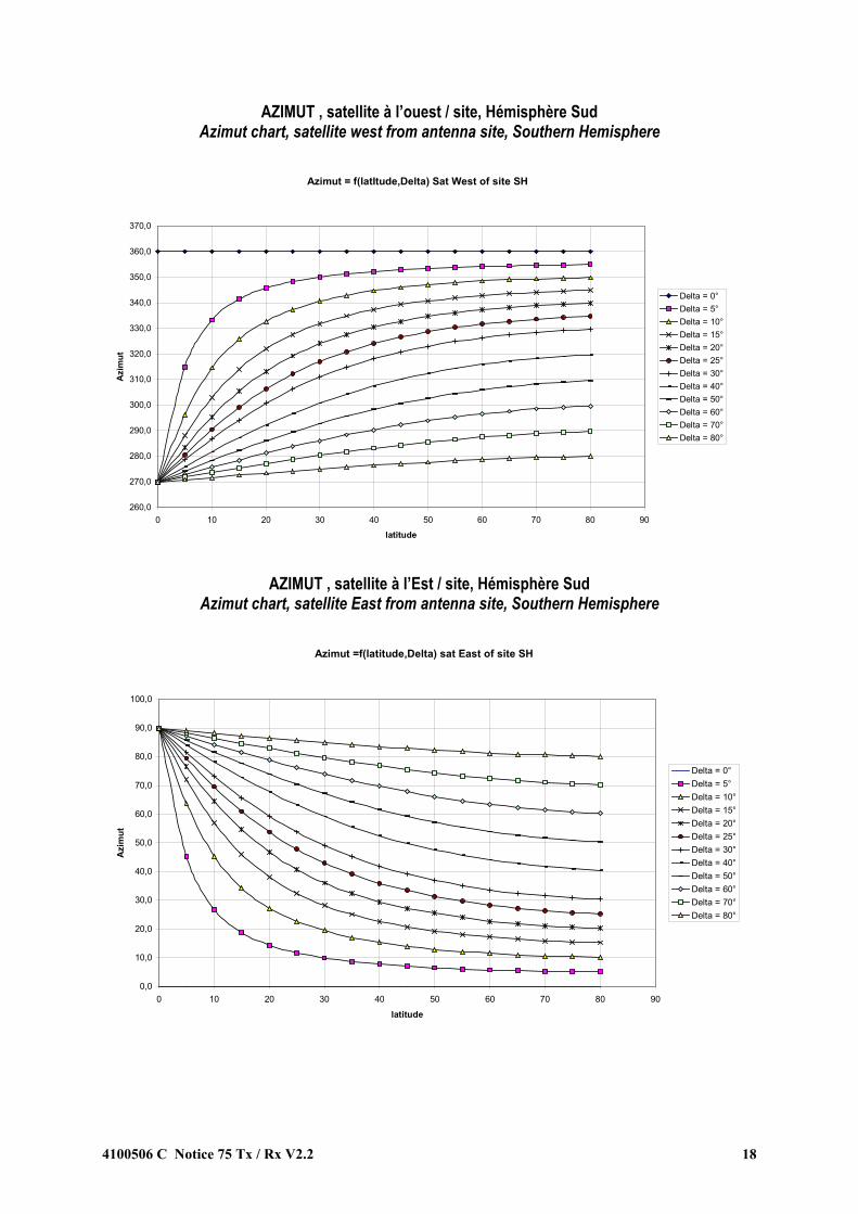
AZIMUT , satellite à l’ouest / site, Hémisphère Sud Azimut chart, satellite west from antenna site, Southern Hemisphere
Azimut = f(latItude,Delta) Sat West of site SH
260,0
270,0
280,0
290,0
300,0
310,0
320,0
330,0
340,0
350,0
360,0
370,0
0 10 20 30 40 50 60 70 80 90
latitude
Azi
mut
Delta = 0°Delta = 5°Delta = 10°Delta = 15°Delta = 20°Delta = 25°Delta = 30°Delta = 40°Delta = 50°Delta = 60°Delta = 70°Delta = 80°
AZIMUT , satellite à l’Est / site, Hémisphère Sud
Azimut chart, satellite East from antenna site, Southern Hemisphere
Azimut =f(latitude,Delta) sat East of site SH
0,0
10,0
20,0
30,0
40,0
50,0
60,0
70,0
80,0
90,0
100,0
0 10 20 30 40 50 60 70 80 90
latitude
Azi
mut
Delta = 0°Delta = 5°Delta = 10°Delta = 15°Delta = 20°Delta = 25°Delta = 30°Delta = 40°Delta = 50°Delta = 60°Delta = 70°Delta = 80°
4100506 C Notice 75 Tx / Rx V2.2 18