Embed Size (px)
DESCRIPTION
Assembly Tooling. T. Brown. Princeton Plasma Physics Laboratory Oak Ridge National Laboratory. PU Workshop on NCSX Cost & Schedule Princeton Plasma Physics Laboratory Princeton, NJ Mar 1-4, 2007. Assembly Tooling (WBS 186). Summarize the tooling requirements for each assembly stage - PowerPoint PPT Presentation
Citation preview
1
Assembly Tooling
PU Workshop on NCSX Cost & SchedulePrinceton Plasma Physics Laboratory
Princeton, NJMar 1-4, 2007
T. Brown
Princeton Plasma Physics Laboratory Oak Ridge National Laboratory

2
Assembly Tooling (WBS 186)
Summarize the tooling requirements for each assembly stage
Provide the tooling design status.
Review the tooling cost estimate for each assembly stage.

3
Stage 1
Stage 3
Stage 5
VV Prep
MCHP installation over VV Period
Final FP Assembly
Stage 2
MC Half Period Assembly
Stage 4
TFHP assembly combined with Stage 5
FPA is accomplished in
five Stages
Stage 6 Final Machine Assembly
4
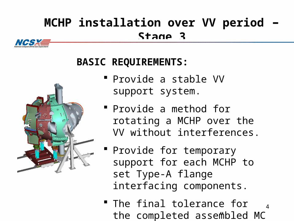
MCHP installation over VV period – Stage 3
Provide a stable VV support system.
Provide a method for rotating a MCHP over the VV without interferences.
Provide for temporary support for each MCHP to set Type-A flange interfacing components.
The final tolerance for the completed assembled MC period is ± 0.020”.
BASIC REQUIREMENTS:

5
The design intent for Stage 3 is pass two modular coil half period assemblies over the VV and accurately position mating flanges…without hitting the VV.
Vacuum Vessel Period
Module Coil Half Period
Module Coil Half Period
6
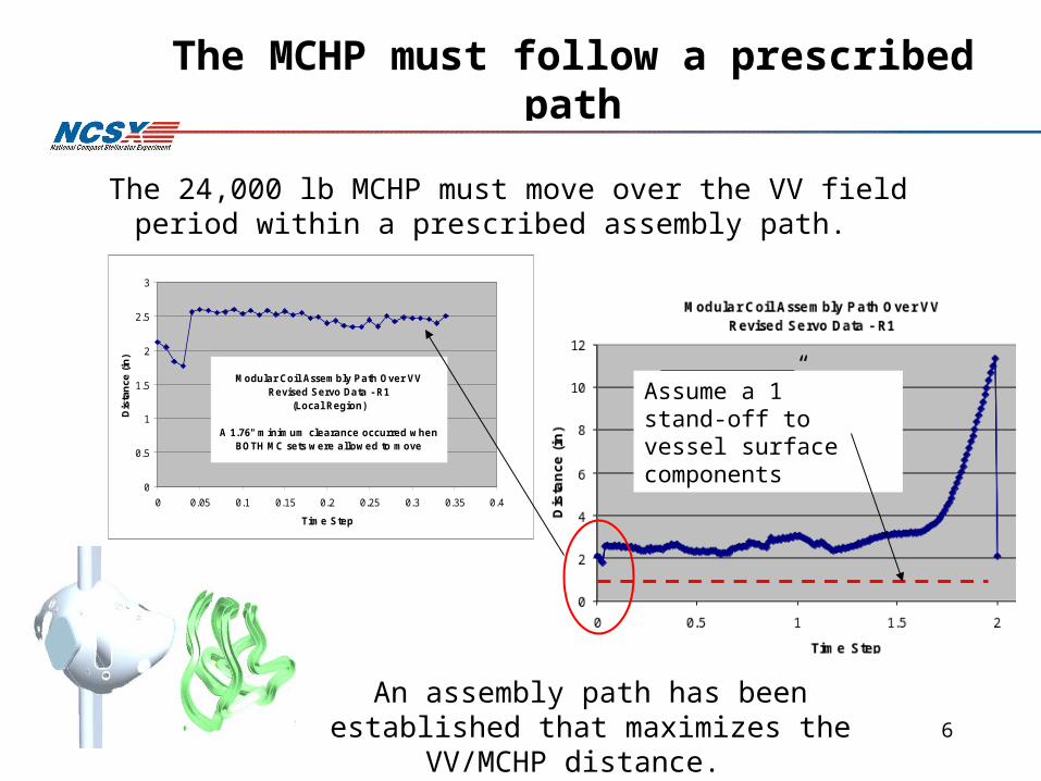
The MCHP must follow a prescribed path
The 24,000 lb MCHP must move over the VV field period within a prescribed assembly path.
An assembly path has been established that maximizes the VV/MCHP distance.
Assume a 1” stand-off to vessel surface components
0
0.5
1
1.5
2
2.5
3
0 0.05 0.1 0.15 0.2 0.25 0.3 0.35 0.4
Time Step
Dis
tan
ce (
in)
Modular Coil Assembly Path Over VVRevised Servo Data - R1
(Local Region)
A 1.76" minimum clearance occurred when BOTH MC sets were allowed to move

7
A 0.45” minimum clearance exists between wing region of Type A’s as the two half period MC shells comes together.
MC to MC Clearance
Wing region

8
Type B distance to shell off-normal points is 1.53” at the 60% step
1.528”

9
R&D activities were used to help developed the Stage 3 assembly approach.
Crane Supported – hand assisted assembly

10
25,000 lb concrete block
120” long, 40” wide and 60” high
MC crane assisted assembly simulation was set up using a concrete block with three lasers mounted to it.
The concrete block motion was controlled by using a combination of the D-site test cell crane and three chain-fall supports mounted to the crane hook.
MC Installation Development Activity

11
The path traveled by each laser was plotted on sheets of velum and mounted to the screens, aligning pre-marked crosshairs located on the screen with marks on the printed paper
One-quarter inch circles were used to define the required laser positions along the curve path.
The block was manipulated to follow the sequential points with an occasional maximum deviation of about ¾” to 1”, all within our allowed assembly tolerances.
Improvements will be made using motor driven mechanical screws with in-line encoder.

12
To improve the accuracy of moving the MCHP we will be replacing the chain falls with mechanized screw systems with inline encoders.
Crane system updated with mechanized screws
The screw mechanism cost is part of Viola’s FPA cost estimate

13
The Stage 3 fixtures will support the MC’s and allow movement for different fit-up conditions.
Metrology measurements taken to establish left MCHP position
The right MCHP is positioned using the crane/mechanized screw system
Pre-fit flange shim installation at Type-A interface.

14
The Stage 3 fixture supports the VV.
Vacuum Vessel supported and is in position to receive left MCHP
• Take metrology measurements
• Define VV position

15
The Stage 3 fixture includes local structure for laser supports, laser path screen surfaces and structure to interface with crane drive system.

16

17
Complete FPA – Stage 5
Provide a stable FP support system for installation of VV ports.
Provide a support method for rotating individual TF coils over each half period.
BASIC REQUIREMENTS:

18
Final FP Assembly– Stage 5
Stage 5 completes the FPA assembly process bringing together the VV/MCHP
assembly, VV ports, TF coils, trim coils and FPA services.
Two large diagnostic ports tack welded in Stage 5.

19
The design have been developed in sufficient detail to define cost and schedule estimates.
The Stage 5 fixture details are preliminary
Stage 5 weldment cost items
FPA base support
Type-C side support

20
Stage 5 assembly design details are preliminary
FPA lowered onto support stand VV ports installed
TF temporarily positionedTF final fit-up

21

22
Final Machine Assembly Fixtures – Stage 6
Provide a stable support system that provides the radial movement of each FPA to their final assembled position.
Provide a stable VV spool support that provides radial and angular movement to their final assembled position.
The final tolerance for the completed machine is ± 0.020”.
BASIC REQUIREMENTS:

23
Stage 6 – Spool piece assembly motion

24
Stage 6 – Machine assembly motion

25
183 lbs
Spool piece support and motion control

26
Each FPA will properly oriented in their final position using the same technique that has been developed in assembling the MCHP’s and then pulled back to a pre-fit position.
Stage 6 incorporates MCHP positioning techniques
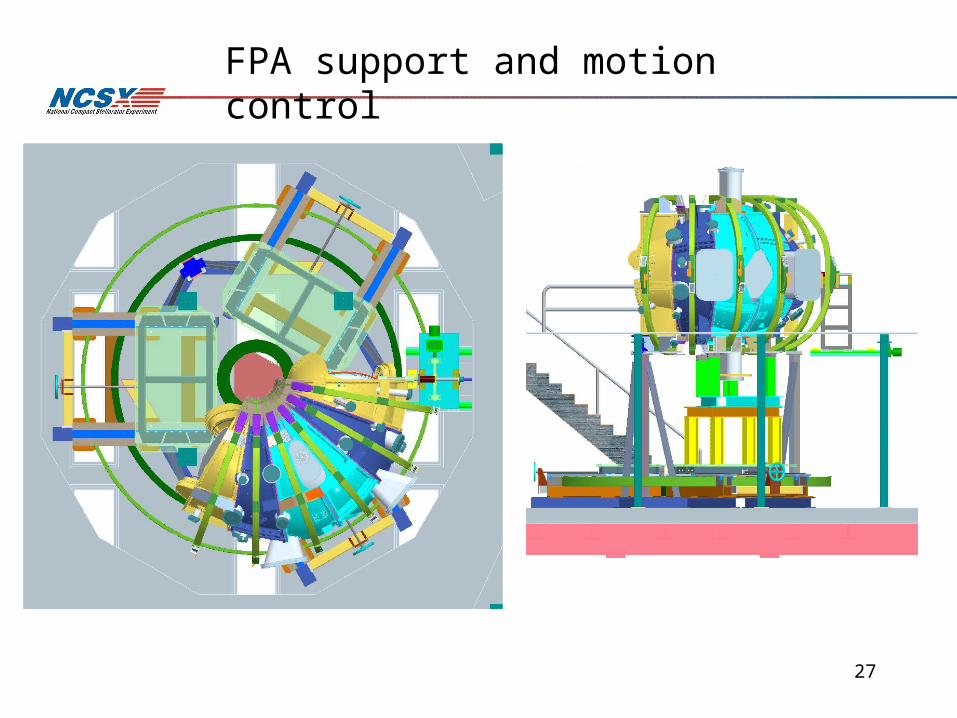
27
FPA support and motion control

28

29
• The FPA tooling design is still in progress– The Stage 3 fixture design is complete and a final design
review scheduled– Stage 4(TF assembly) has been combined with Stage 5– 5 and 6 fixture designs are in progress
• Additional small scale tooling and handling fixtures will be developed as they are identified.
• The assembly design and fixture details will continue to be updated through design review and the prototyping process
Summary

![MBD-Based Parallel Change Management for Aircraft Assembly … · CATIA V5 and ProE. Pan [5] put forward a kind of assembly tooling variant design method based on axiomatic design](https://img.pdfslide.us/doc/110x75/611a7ea46f8ffc4b8e4a6d50/mbd-based-parallel-change-management-for-aircraft-assembly-catia-v5-and-proe-pan.jpg)