Embed Size (px)
Citation preview
SUPER KRAFT Monocoupe 90A
Assembly Manual
KANGKE INDUSTRIAL USA Inc. 65 East Jefryn Blvd. Deer Park New York 11729
http://www.kangkeusa.com E-mail: [email protected] 1-877-203-2377 Fax 1-631-274-3296
Warranty: Kangke Industrial USA Inc. guarantees the kit to be free of defects in both material and workmanship at the date of purchase. This warranty does not cover any parts damaged by use or modifications. In no case shall Kangke Industrial’s liability exceed the purchase cost of this kit. Since Kangke Industrial has no control of final assembly and material used by user for final assembly, no liability shall be assumed or accepted for any damage resulting from the use by user of final use-assembled products. This kit has been flight tested for normal use. If the plane will be used for extremely high stress flying, the modeler is responsible for reinforcing the high stress points. Inspect this kit immediately after receiving it,report any missing and damaged parts within 10 business days otherwise the claim may be denied.
1
1/4 scale Monocoupe 90A The original Monocoupe was produced in a number of models from 1931 to around 1940. The 90A was 20’6” long with a 32’ wingspan, it had an empty weight of 940 pounds with a useful load of 640 pounds. Powered by a 90 horsepower Lampert radial engine, it could reach level speeds of 130 miles per hour, climb at almost 1000 feet per minute, and had a service ceiling of 15000 feet. It was one of the highest performance civilian aircraft of the golden age, and even by standards today, the performance would be considered exceptional for the horsepower. The Monocoupes beautiful lines and wonderful flight characteristics made it a favorite for pilots of the day and a true collectors item today. Super Kraft made every effort to retain all the wonderful qualities of the original and we are sure you will be pleased with the result. The current trend in the RC world is to more power, we at Super Kraft urge you to resist overpowering this aircraft. We have tested the airframe with engines from 91 glow to 2.4 gas and here is what we found. The 91 two stroke and 120 four stroke gave very scale like performance. Take off roll on grass was about 75 feet with out flaps and about 50 feet with flaps. Normal flight was done at around ¾ throttle, with a shallow dive needed for round loops at full throttle. The 150 four stroke reduced the take off roll to 30 feet without flaps and 20 feet with, a good match for the airframe. The 2.4 gas had a take off roll of about 20 feet without flaps and too short to measure with, however the 20/10 propeller on the 2.4 caused trouble with ground clearance and the thrust at idle was too high to land the plane with flaps. The additional weight of the 2.4 also caused the need for some ballast added to the tail. Our favorite engine was the RCS 140 gas {RC Showcase [301 374 2197] rcshowcase.com}. Using an 18/6 prop the takeoff roll with out flaps was about 30 feet and about 20 feet with. Landings were easy both with and without flaps, normal flight was at and below ½ throttle, loops were easy at any speed, and no ballast was needed for balance. Under most conditions this engine has more power than the aircraft can use, plus the economy, sound and reliable idle that is making gas so popular. WARNING! As model aircraft get larger and more powerful, the risk for injury increases. KANGKE’s extensive testing procedures insure a high quality kit that has gone through many steps to provide you with a safe reliable airframe. Nothing we can do however will make up for poor assembly or irresponsible behavior at the field. A model this size and weight traveling at 60 MPH contains enough energy that if it were to contact another person, the injuries would be extensive, possibly fatal. The safe operation of this model is yours and yours alone. If you are a beginner or have never flown a model of this size and power, you should not make the attempt without the help of an experienced pilot.
This Manuel is the sole property of Kangke Industrial USA, Inc. Reproducing any part
without the consent of Kangke Industrial USA, Inc. is a lawful violation.
Read each step of the instructions carefully. Be sure you understand what is required and what the procedure is before you glue or cut anything. How well you assemble this model will have a
direct effect on its flight characteristics. If you are familiar with the assembly of ARF type aircraft you will find the order of assembly
steps in this manual to be unusual, this was necessary to insure the fastest, most accurate assembly possible. Super Kraft recommends you follow the assembly order as shown.
2
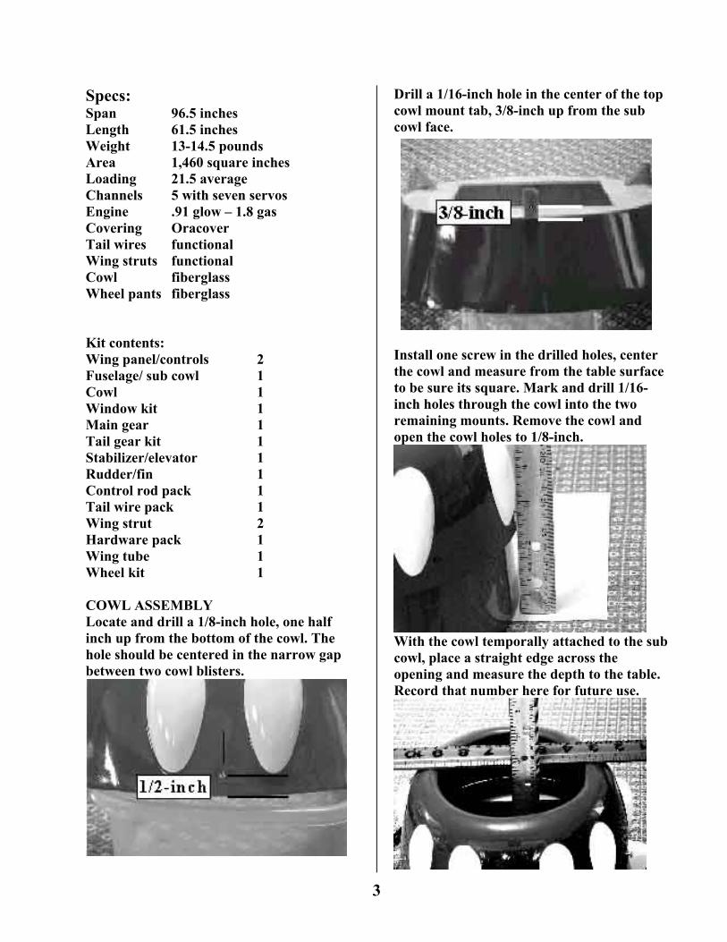
Specs: Span 96.5 inches Length 61.5 inches Weight 13-14.5 pounds Area 1,460 square inches Loading 21.5 average Channels 5 with seven servos Engine .91 glow – 1.8 gas Covering Oracover Tail wires functional Wing struts functional Cowl fiberglass Wheel pants fiberglass Kit contents: Wing panel/controls 2 Fuselage/ sub cowl 1 Cowl 1 Window kit 1 Main gear 1 Tail gear kit 1 Stabilizer/elevator 1 Rudder/fin 1 Control rod pack 1 Tail wire pack 1 Wing strut 2 Hardware pack 1 Wing tube 1 Wheel kit 1 COWL ASSEMBLY Locate and drill a 1/8-inch hole, one half inch up from the bottom of the cowl. The hole should be centered in the narrow gap between two cowl blisters.
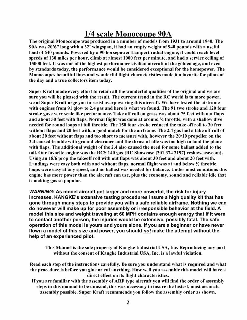
Drill a 1/16-inch hole in the center of the top cowl mount tab, 3/8-inch up from the sub cowl face.
Install one screw in the drilled holes, center the cowl and measure from the table surface to be sure its square. Mark and drill 1/16-inch holes through the cowl into the two remaining mounts. Remove the cowl and open the cowl holes to 1/8-inch.
With the cowl temporally attached to the sub cowl, place a straight edge across the opening and measure the depth to the table. Record that number here for future use.
3
FUSELAGE Because the fuselage is round, installing the main gear will make the fuselage more stable and easier to handle. Remove the taped on belly pan. Install the main gear with the supplied Allen screws and washers. When installed the gear should have a forward sweep and the belly pan attach screw hole should be at the front.
Test fit the belly pan and install the “T” nuts inside the fuselage. Open the guide holes in the fuselage to fit the nuts.
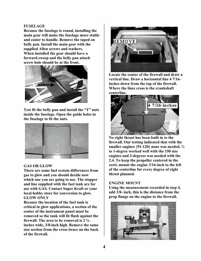
GAS OR GLOW There are some fuel system differences from gas to glow and you should decide now which one you are going to use. The stopper and line supplied with the fuel tank are for use with GAS. Contact Super Kraft or your local hobby store for conversion to glow. GLOW ONLY Because the location of the fuel tank is critical in glow applications, a section of the center of the instrument panel must be removed so the tank will fit flush against the firewall. The area to be removed is 2 ¾- inches wide, 3/8-inch high. Remove the same size section from the cross brace on the back of the firewall.
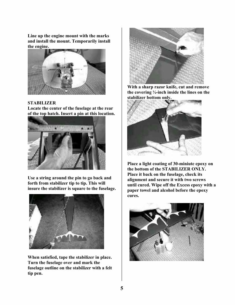
Locate the center of the firewall and draw a vertical line. Draw a horizontal line 4 7/16-inches down from the top of the firewall. Where the lines cross is the crankshaft centerline.
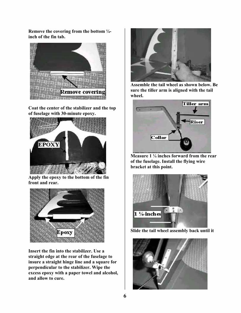
No right thrust has been built in to the firewall. Our testing indicated that with the smaller engines {91-120} none was needed. ¾ to 1-degree worked well with the 150 size engines and 2-degrees was needed with the 2.4. To keep the propeller centered in the cowl, mount the engine 3/16-inch to the left of the centerline for every degree of right thrust planned. ENGINE MOUNT Using the measurement recorded in step 4, add 3/8- inch, this is the distance from the prop flange on the engine to the firewall.
4
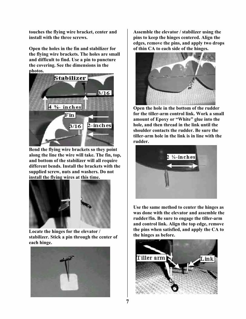
Line up the engine mount with the marks and install the mount. Temporarily install the engine.
STABILIZER Locate the center of the fuselage at the rear of the top hatch. Insert a pin at this location.
Use a string around the pin to go back and forth from stabilizer tip to tip. This will insure the stabilizer is square to the fuselage.
When satisfied, tape the stabilizer in place. Turn the fuselage over and mark the fuselage outline on the stabilizer with a felt tip pen.
With a sharp razor knife, cut and remove the covering ¼-inch inside the lines on the stabilizer bottom only.
Place a light coating of 30-miniute epoxy on the bottom of the STABILIZER ONLY. Place it back on the fuselage, check its alignment and secure it with two screws until cured. Wipe off the Excess epoxy with a paper towel and alcohol before the epoxy cures.
5
Remove the covering from the bottom ¼-inch of the fin tab.
Coat the center of the stabilizer and the top of fuselage with 30-minute epoxy.
Apply the epoxy to the bottom of the fin front and rear.
Insert the fin into the stabilizer. Use a straight edge at the rear of the fuselage to insure a straight hinge line and a square for perpendicular to the stabilizer. Wipe the excess epoxy with a paper towel and alcohol, and allow to cure.
Assemble the tail wheel as shown below. Be sure the tiller arm is aligned with the tail wheel.
Measure 1 ¼ inches forward from the rear of the fuselage. Install the flying wire bracket at this point.
Slide the tail wheel assembly back until it
6
touches the flying wire bracket, center and install with the three screws. Open the holes in the fin and stabilizer for the flying wire brackets. The holes are small and difficult to find. Use a pin to puncture the covering. See the dimensions in the photos.
Bend the flying wire brackets so they point along the line the wire will take. The fin, top, and bottom of the stabilizer will all require different bends. Install the brackets with the supplied screw, nuts and washers. Do not install the flying wires at this time.
Locate the hinges for the elevator / stabilizer. Stick a pin through the center of each hinge.
Assemble the elevator / stabilizer using the pins to keep the hinges centered. Align the edges, remove the pins, and apply two drops of thin CA to each side of the hinges.
Open the hole in the bottom of the rudder for the tiller-arm control link. Work a small amount of Epoxy or “White” glue into the hole, and then thread in the link until the shoulder contacts the rudder. Be sure the tiller-arm hole in the link is in line with the rudder.
Use the same method to center the hinges as was done with the elevator and assemble the rudder/fin. Be sure to engage the tiller-arm and control link. Align the top edge, remove the pins when satisfied, and apply the CA to the hinges as before.
7
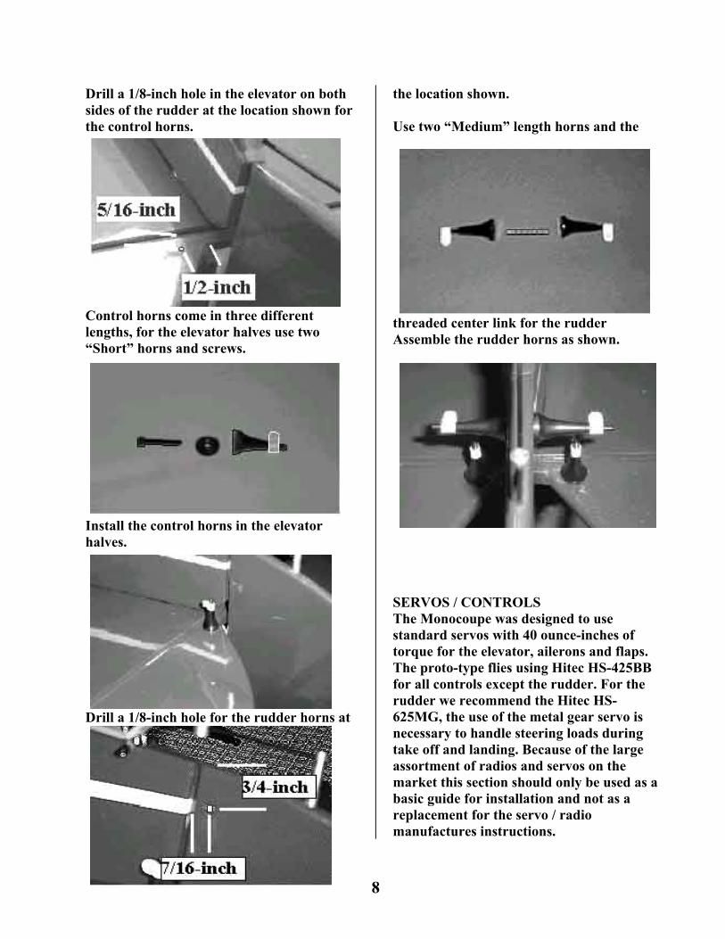
Drill a 1/8-inch hole in the elevator on both sides of the rudder at the location shown for the control horns.
8
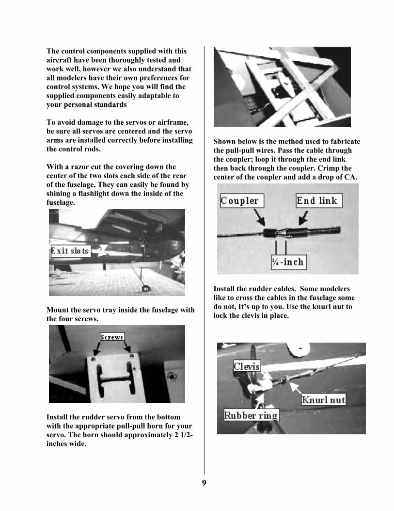
Control horns come in three different lengths, for the elevator halves use two “Short” horns and screws.
Install the control horns in the elevator halves.
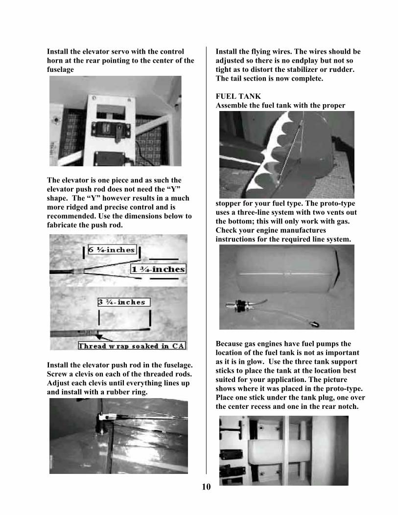
Drill a 1/8-inch hole for the rudder horns at
the location shown. Use two “Medium” length horns and the
threaded center link for the rudder Assemble the rudder horns as shown.
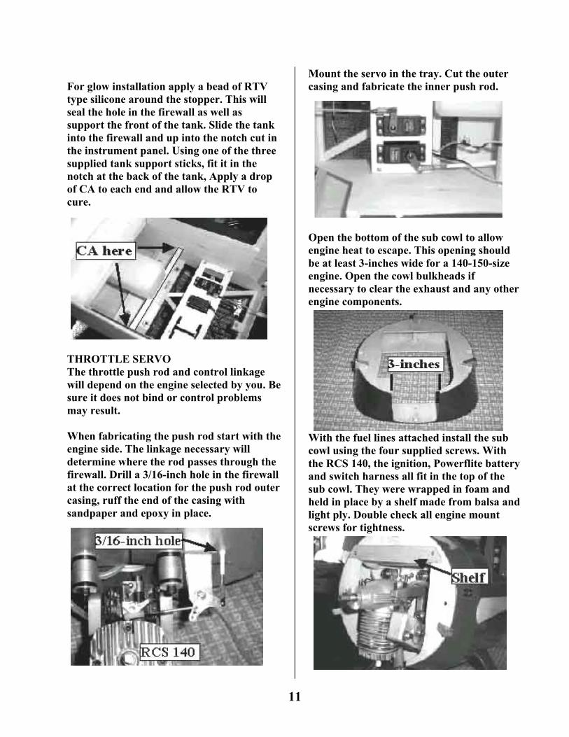
SERVOS / CONTROLS The Monocoupe was designed to use standard servos with 40 ounce-inches of torque for the elevator, ailerons and flaps. The proto-type flies using Hitec HS-425BB for all controls except the rudder. For the rudder we recommend the Hitec HS-625MG, the use of the metal gear servo is necessary to handle steering loads during take off and landing. Because of the large assortment of radios and servos on the market this section should only be used as a basic guide for installation and not as a replacement for the servo / radio manufactures instructions.
The control components supplied with this aircraft have been thoroughly tested and work well, however we also understand that all modelers have their own preferences for control systems. We hope you will find the supplied components easily adaptable to your personal standards To avoid damage to the servos or airframe, be sure all servos are centered and the servo arms are installed correctly before installing the control rods. With a razor cut the covering down the center of the two slots each side of the rear of the fuselage. They can easily be found by shining a flashlight down the inside of the fuselage.
Mount the servo tray inside the fuselage with the four screws.
Install the rudder servo from the bottom with the appropriate pull-pull horn for your servo. The horn should approximately 2 1/2-inches wide.
Shown below is the method used to fabricate the pull-pull wires. Pass the cable through the coupler; loop it through the end link then back through the coupler. Crimp the center of the coupler and add a drop of CA.
Install the rudder cables. Some modelers like to cross the cables in the fuselage some do not, It’s up to you. Use the knurl nut to lock the clevis in place.
9
Install the elevator servo with the control horn at the rear pointing to the center of the fuselage
The elevator is one piece and as such the elevator push rod does not need the “Y” shape. The “Y” however results in a much more ridged and precise control and is recommended. Use the dimensions below to fabricate the push rod.
Install the elevator push rod in the fuselage. Screw a clevis on each of the threaded rods. Adjust each clevis until everything lines up and install with a rubber ring.
Install the flying wires. The wires should be adjusted so there is no endplay but not so tight as to distort the stabilizer or rudder. The tail section is now complete. FUEL TANK Assemble the fuel tank with the proper
stopper for your fuel type. The proto-type uses a three-line system with two vents out the bottom; this will only work with gas. Check your engine manufactures instructions for the required line system.
Because gas engines have fuel pumps the location of the fuel tank is not as important as it is in glow. Use the three tank support sticks to place the tank at the location best suited for your application. The picture shows where it was placed in the proto-type. Place one stick under the tank plug, one over the center recess and one in the rear notch.
10
For glow installation apply a bead of RTV type silicone around the stopper. This will seal the hole in the firewall as well as support the front of the tank. Slide the tank into the firewall and up into the notch cut in the instrument panel. Using one of the three supplied tank support sticks, fit it in the notch at the back of the tank, Apply a drop of CA to each end and allow the RTV to cure.
THROTTLE SERVO The throttle push rod and control linkage will depend on the engine selected by you. Be sure it does not bind or control problems may result. When fabricating the push rod start with the engine side. The linkage necessary will determine where the rod passes through the firewall. Drill a 3/16-inch hole in the firewall at the correct location for the push rod outer casing, ruff the end of the casing with sandpaper and epoxy in place.
Mount the servo in the tray. Cut the outer casing and fabricate the inner push rod.
Open the bottom of the sub cowl to allow engine heat to escape. This opening should be at least 3-inches wide for a 140-150-size engine. Open the cowl bulkheads if necessary to clear the exhaust and any other engine components.
With the fuel lines attached install the sub cowl using the four supplied screws. With the RCS 140, the ignition, Powerflite battery and switch harness all fit in the top of the sub cowl. They were wrapped in foam and held in place by a shelf made from balsa and light ply. Double check all engine mount screws for tightness.
11
With everything hooked up to the engine install the cowl, propeller and spinner. The front is now finished.
Double check to be sure the landing gear bolts are tight. Install the belly pan on the fuselage with the provided screws.
Install the landing gear fuselage fairing pair. Be sure the notch is over the wing strut-attaching hole. Use canopy adhesive and tape in place till dry.
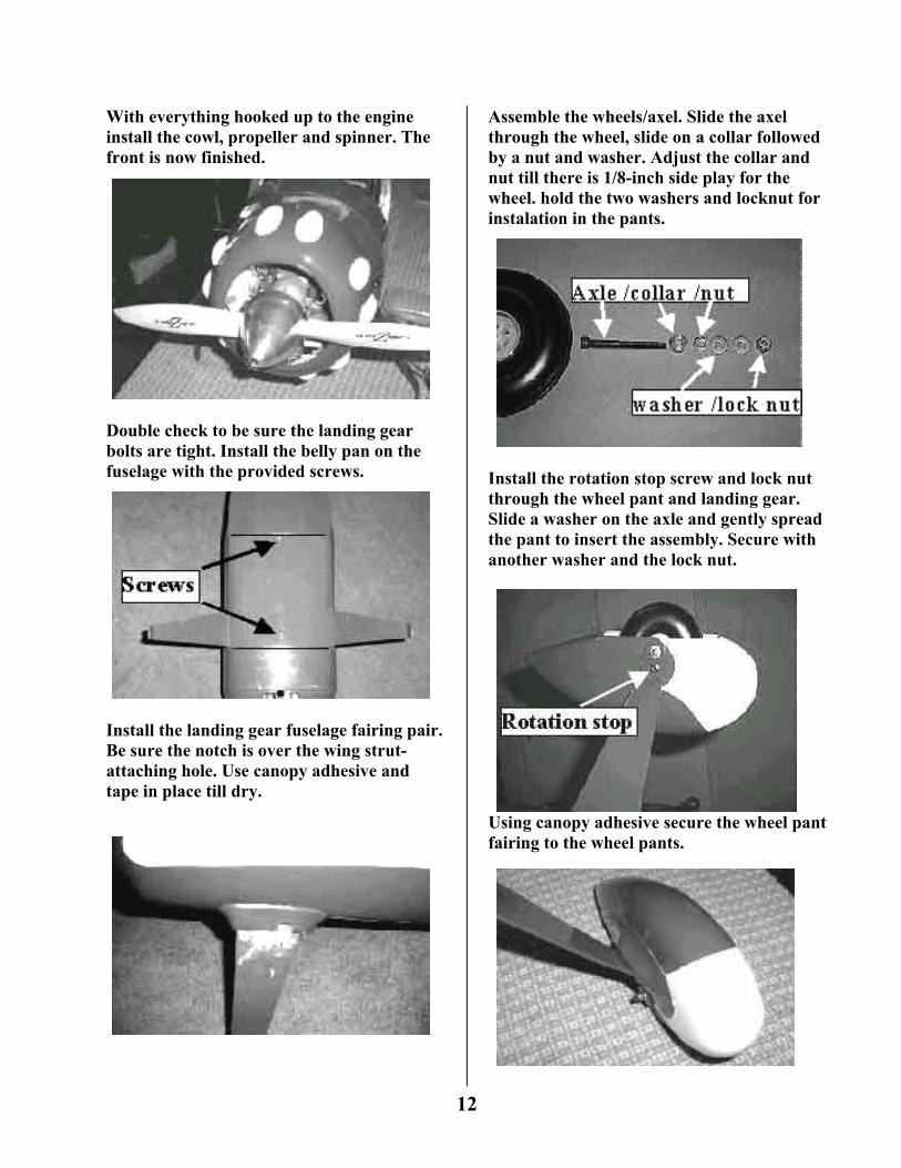
Assemble the wheels/axel. Slide the axel through the wheel, slide on a collar followed by a nut and washer. Adjust the collar and nut till there is 1/8-inch side play for the wheel. hold the two washers and locknut for instalation in the pants.
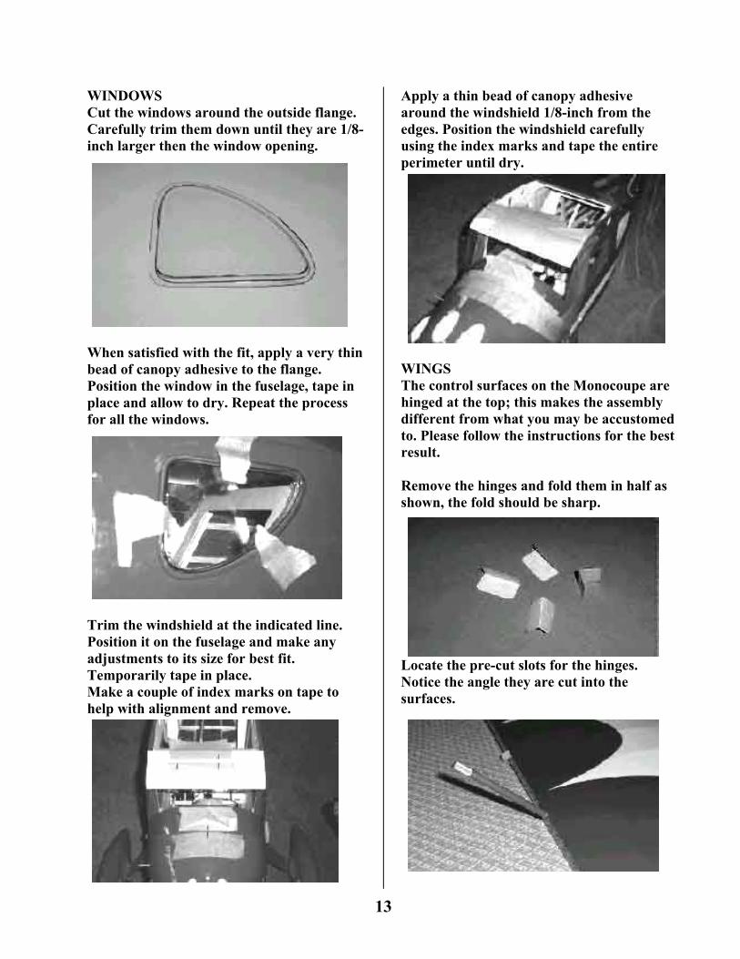
Install the rotation stop screw and lock nut through the wheel pant and landing gear. Slide a washer on the axle and gently spread the pant to insert the assembly. Secure with another washer and the lock nut.
Using canopy adhesive secure the wheel pant fairing to the wheel pants.
12
WINDOWS Cut the windows around the outside flange. Carefully trim them down until they are 1/8-inch larger then the window opening.
When satisfied with the fit, apply a very thin bead of canopy adhesive to the flange. Position the window in the fuselage, tape in place and allow to dry. Repeat the process for all the windows.
Trim the windshield at the indicated line. Position it on the fuselage and make any adjustments to its size for best fit. Temporarily tape in place. Make a couple of index marks on tape to help with alignment and remove.
Apply a thin bead of canopy adhesive around the windshield 1/8-inch from the edges. Position the windshield carefully using the index marks and tape the entire perimeter until dry.
WINGS The control surfaces on the Monocoupe are hinged at the top; this makes the assembly different from what you may be accustomed to. Please follow the instructions for the best result. Remove the hinges and fold them in half as shown, the fold should be sharp.
Locate the pre-cut slots for the hinges. Notice the angle they are cut into the surfaces.
13
Insert the hinge all the way to the fold. Install the control surfaces leaving a 1/8-inch gap at both ends of the aileron. Apply two drops of thin CA to the all the tops of the hinges, followed by two drops on the bottom.
Material is supplied to seal the hinge line between the ailerons / flaps and the wing. This not only adds strength to the hinge line, it also increases control response. To perform this step a covering iron should be used, however a laundry iron will work if it can reach a temperature of 300 degrees. Start with the aileron, select a long piece of trim covering and cut to size.
Remove the backing and tack to the wing at one end. Pull it tight and tack at the other end. Allow the aileron to hang off the edge of the table and secure the strip to the wing. Go slow and avoid bubbles, should a bubble appear puncture it with a pin.
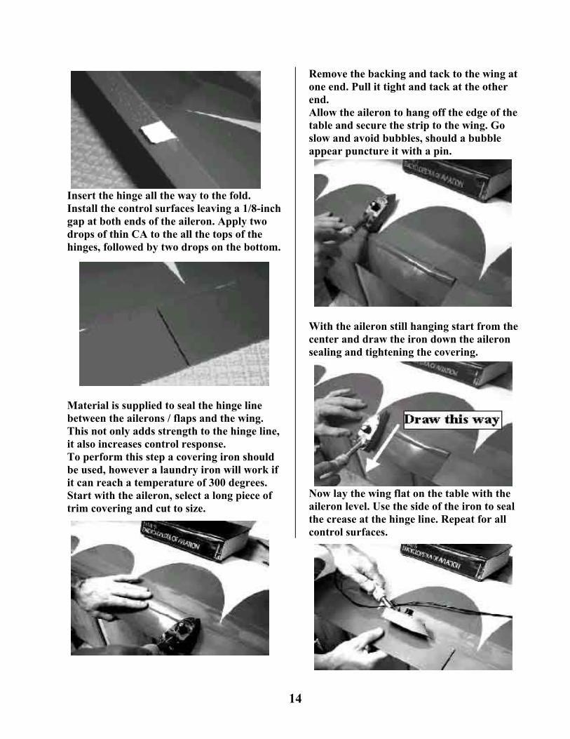
With the aileron still hanging start from the center and draw the iron down the aileron sealing and tightening the covering.
Now lay the wing flat on the table with the aileron level. Use the side of the iron to seal the crease at the hinge line. Repeat for all control surfaces.
14
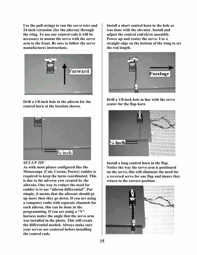
Use the pull strings to run the servo wire and 24-inch extension {for the aileron} through the wing. To use our control rods it will be necessary to mount the servo with the servo arm to the front. Be sure to follow the servo manufactures instructions.
Drill a 1/8-inch hole in the aileron for the control horn at the location shown.
SET-UP TIP As with most planes configured like the Monocoupe {Cub, Cessna, Porter} rudder is required to keep the turns coordinated. This is due to the adverse yaw created by the ailerons. One way to reduce the need for rudder is to use “aileron differential”. Put simply, it means that the ailerons should go up more then they go down. If you are using a computer radio with separate channels for each aileron, this can be done in the programming. If you are using a “Y” harness notice the angle that the servo arm was installed in the photo. This will create the differential needed. Always make sure your servos are centered before installing the control rods.
Install a short control horn in the hole as was done with the elevator. Install and adjust the control rod/clevis assembly. Power up and center the servo. Use a straight edge on the bottom of the wing to set the rod length.
Drill a 1/8-inch hole in line with the servo center for the flap horn
Install a long control horn in the flap. Notice the way the servo arm is positioned on the servo, this will eliminate the need for a reversed servo for one flap and insure they return to the correct position.
15
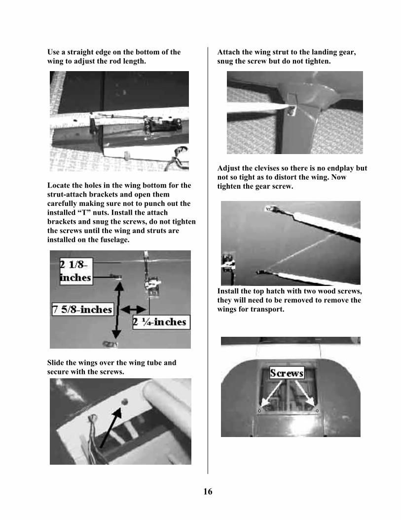
Use a straight edge on the bottom of the wing to adjust the rod length.
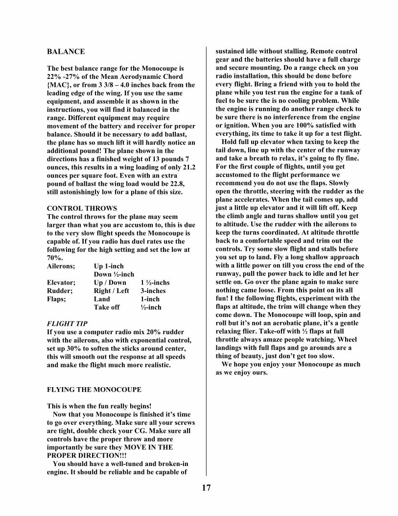
Locate the holes in the wing bottom for the strut-attach brackets and open them carefully making sure not to punch out the installed “T” nuts. Install the attach brackets and snug the screws, do not tighten the screws until the wing and struts are installed on the fuselage.
Slide the wings over the wing tube and secure with the screws.
Attach the wing strut to the landing gear, snug the screw but do not tighten.
Adjust the clevises so there is no endplay but not so tight as to distort the wing. Now tighten the gear screw.
Install the top hatch with two wood screws, they will need to be removed to remove the wings for transport.
16
BALANCE The best balance range for the Monocoupe is 22% -27% of the Mean Aerodynamic Chord {MAC}, or from 3 3/8 – 4.0 inches back from the leading edge of the wing. If you use the same equipment, and assemble it as shown in the instructions, you will find it balanced in the range. Different equipment may require movement of the battery and receiver for proper balance. Should it be necessary to add ballast, the plane has so much lift it will hardly notice an additional pound! The plane shown in the directions has a finished weight of 13 pounds 7 ounces, this results in a wing loading of only 21.2 ounces per square foot. Even with an extra pound of ballast the wing load would be 22.8, still astonishingly low for a plane of this size. CONTROL THROWS The control throws for the plane may seem larger than what you are accustom to, this is due to the very slow flight speeds the Monocoupe is capable of. If you radio has duel rates use the following for the high setting and set the low at 70%. Ailerons; Up 1-inch
Down ½-inch Elevator; Up / Down 1 ½-inchs Rudder; Right / Left 3-inches Flaps; Land 1-inch Take off ½-inch FLIGHT TIP If you use a computer radio mix 20% rudder with the ailerons, also with exponential control, set up 30% to soften the sticks around center, this will smooth out the response at all speeds and make the flight much more realistic. FLYING THE MONOCOUPE This is when the fun really begins!
Now that you Monocoupe is finished it’s time to go over everything. Make sure all your screws are tight, double check your CG. Make sure all controls have the proper throw and more importantly be sure they MOVE IN THE PROPER DIRECTION!!!
You should have a well-tuned and broken-in engine. It should be reliable and be capable of
sustained idle without stalling. Remote control gear and the batteries should have a full charge and secure mounting. Do a range check on you radio installation, this should be done before every flight. Bring a friend with you to hold the plane while you test run the engine for a tank of fuel to be sure the is no cooling problem. While the engine is running do another range check to be sure there is no interference from the engine or ignition. When you are 100% satisfied with everything, its time to take it up for a test flight.
Hold full up elevator when taxing to keep the tail down, line up with the center of the runway and take a breath to relax, it’s going to fly fine. For the first couple of flights, until you get accustomed to the flight performance we recommend you do not use the flaps. Slowly open the throttle, steering with the rudder as the plane accelerates. When the tail comes up, add just a little up elevator and it will lift off. Keep the climb angle and turns shallow until you get to altitude. Use the rudder with the ailerons to keep the turns coordinated. At altitude throttle back to a comfortable speed and trim out the controls. Try some slow flight and stalls before you set up to land. Fly a long shallow approach with a little power on till you cross the end of the runway, pull the power back to idle and let her settle on. Go over the plane again to make sure nothing came loose. From this point on its all fun! I the following flights, experiment with the flaps at altitude, the trim will change when they come down. The Monocoupe will loop, spin and roll but it’s not an aerobatic plane, it’s a gentle relaxing flier. Take-off with ½ flaps at full throttle always amaze people watching. Wheel landings with full flaps and go arounds are a thing of beauty, just don’t get too slow.
We hope you enjoy your Monocoupe as much as we enjoy ours.
17


![Man and World Volume 7 Issue 4 1974 [Doi 10.1007_bf01246815] Laurence Lampert -- Heidegger's Nietzsche Interpretation](https://img.pdfslide.us/doc/110x75/577ccfd21a28ab9e7890abd0/man-and-world-volume-7-issue-4-1974-doi-101007bf01246815-laurence-lampert.jpg)