Embed Size (px)
Citation preview

STAKS BENCHING™
ASSEMBLY INSTRUCTIONS

TABLE OF CONTENTS
BASE ASSEMBLY 3
ORGANIZER INSTALLATION 4-5
PRIVACY SCREEN INSTALLATION 6
WORKSURFACE INSTALLATION 7
TOP STRAP INSTALLATION 8-9
POWER INSTALLATION - PREMIUM AND BASIC KITS 10-11
POWER INSTALLATION - ECONOMY KIT 12-13
TOP STRAP INSTALLATION & CABLE BASKET ASSEMBLY 14
CABLE BASKET INSTALLATION 15
STAKS BENCHING™ | 3
1. Begin assembly of bench in its permanent location. Once assembled the bench
will be difficult to move.
2. Attach T-nuts to H-bases using M6 x 16MM (Part #: 1416448) screws. Screw
through mount plate from below and into T-nut.
3. Screw into T-nut only two or three turns, DO NOT tighten.
4. Attach toolbar by sliding T-nut into bottom grooved section of toolbar.
5. Align H-bases so they are perpendicular to the toolbars and all toolbars are in a
straight line.
6. Toolbars must be flush to edge of outside bases and centered on the middle
base(s).
7. When toolbars are properly located, tighten screws.
BASE ASSEMBLY
Align H-bases
90°
T-Nut
T-Nut
Page 1
BASE ASSEMBLY
Begin assembly of bench in its permanent location. Once assembled• the bench will be difficult to move.
Attach T-nuts to H-bases using M6 x 16MM screws. Screw through• mount plate from below and into T-nut.
Screw into T-nut only two or three turns, DO NOT tighten.•Attach toolbar by sliding T-nut into bottom grooved section of toolbar.•Align H-bases so they are perpendicular to the toolbars and all toolbars•
are in a straight line Toolbars must be flush to edge of outside bases and centered on the•
middle base(s).When toolbars are properly located, tighten screws. •
Series: Part #:
T-Nut
T-Nut
90˚
Align H-Bases
Ships with H-base. Part #: 1552073
T-Nut
T-Nut
Center Base Model:6-42CHBA16-30CHBA1
Model Numbers:6-64HBA26-48HBA2
“O” Leg Model Numbers:6-64OBA26-48OBA2 Longer than end
base T-Nut.Part #: 1552074
4 | STAKS BENCHING™
Stanchion
UpperExtrusion
LowerExtrusion
ORGANIZER INSTALLATIONFor benches without organizers, proceed
to page 4.
Attach stanchions to bottom of organizer by screwing #8 x 1"screws through stanchion into pre-bored pilot holes.
Remove extrusions from toolbar.•Upper extrusions will not be present if wood privacy•
panels are to be installed.Take note of holes bored through toolbar. •The holes in the bottom of the stanchions will align•
with the holes in the toolbar. Page 2
Series: Part #:
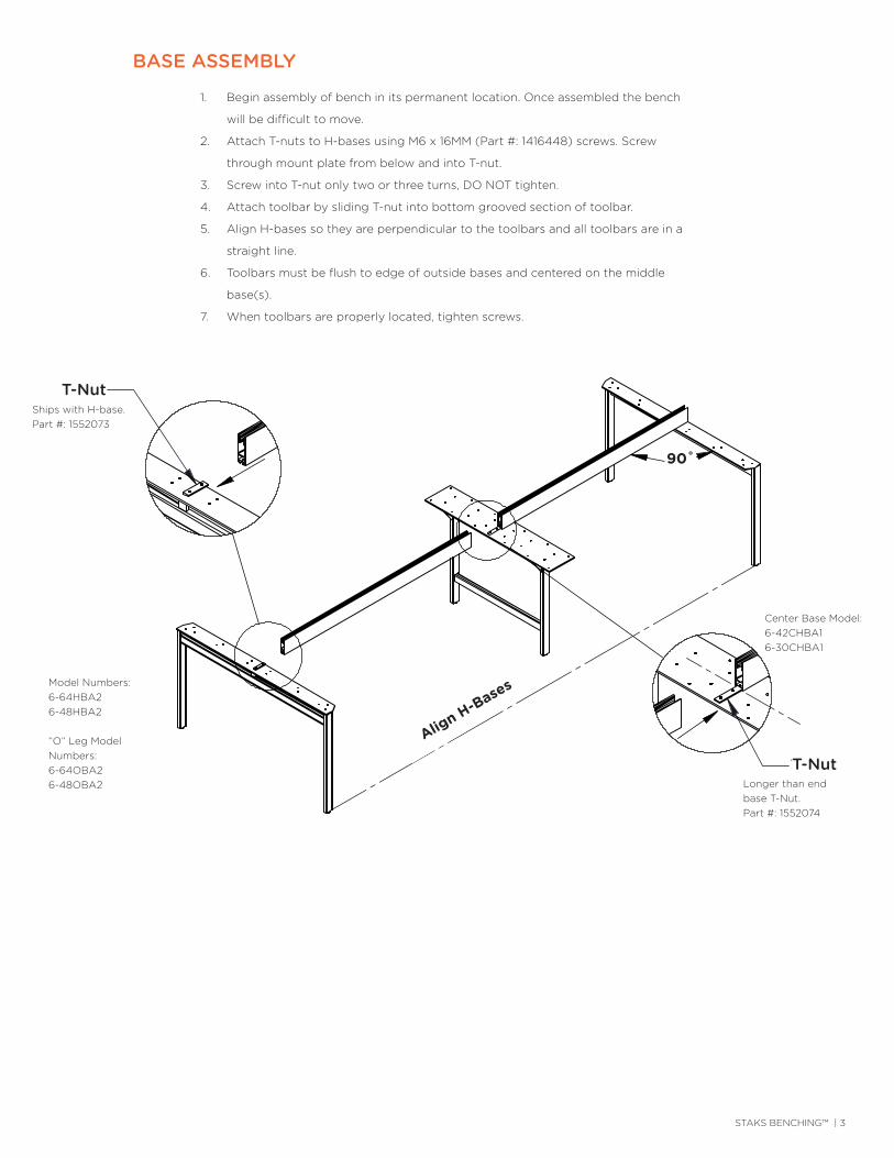
1. Attach stanchion to bottom of organizer by screwing #8 x 1” screws through
stanchion into pre-bored pilot holes.
2. Remove extrusions from toolbar.
3. Upper extrusions will not be present if wood privacy panels are to be installed.
4. Take note of holes bored through toolbar.
5. The holes in the bottom of the stanchions will align with the holes in the toolbar.
ORGANIZER INSTALLATION
Stanchion
UpperExtrusion
LowerExtrusion
ORGANIZER INSTALLATIONFor benches without organizers, proceed
to page 4.
Attach stanchions to bottom of organizer by screwing #8 x 1"screws through stanchion into pre-bored pilot holes.
Remove extrusions from toolbar.•Upper extrusions will not be present if wood privacy•
panels are to be installed.Take note of holes bored through toolbar. •The holes in the bottom of the stanchions will align•
with the holes in the toolbar. Page 2
Series: Part #:
Stanchion
UpperExtrusion
LowerExtrusion
Model Number: 6-SSS
STAKS BENCHING™ | 5
Distance A
Distance B
Distance A
ORGANIZER INSTALLATIONContinued
For benches without organizers, proceedto page 4.
Determine distances shown above and cut extrusions to match.•Extrusions can be cut with a utility knife.•Replace extrusions leaving space for stanchions.•
Drop organizers in place.•Make sure the holes in the bottom of the stanchions are aligned with•
the holes in the toolbar.
Page 3Series: Part #:
Distance A
Distance B
Distance A
ORGANIZER INSTALLATIONContinued
For benches without organizers, proceedto page 4.
Determine distances shown above and cut extrusions to match.•Extrusions can be cut with a utility knife.•Replace extrusions leaving space for stanchions.•
Drop organizers in place.•Make sure the holes in the bottom of the stanchions are aligned with•
the holes in the toolbar.
Page 3Series: Part #:
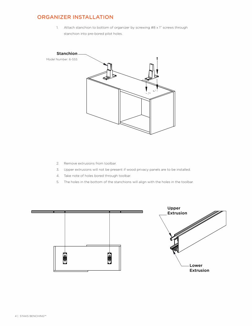
6. Determine distances shown above and cut extrusions to match.
7. Extrusions can be cut with a utility knife.
8. Replace extrusions leaving space for stanchions.
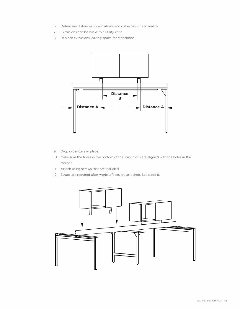
9. Drop organizers in place.
10. Make sure the holes in the bottom of the stanchions are aligned with the holes in the
toolbar.
11. Attach using screws that are included.
12. Straps are required after worksurfaces are attached. See page 8.
Distance ADistance A
Distance B
6 | STAKS BENCHING™
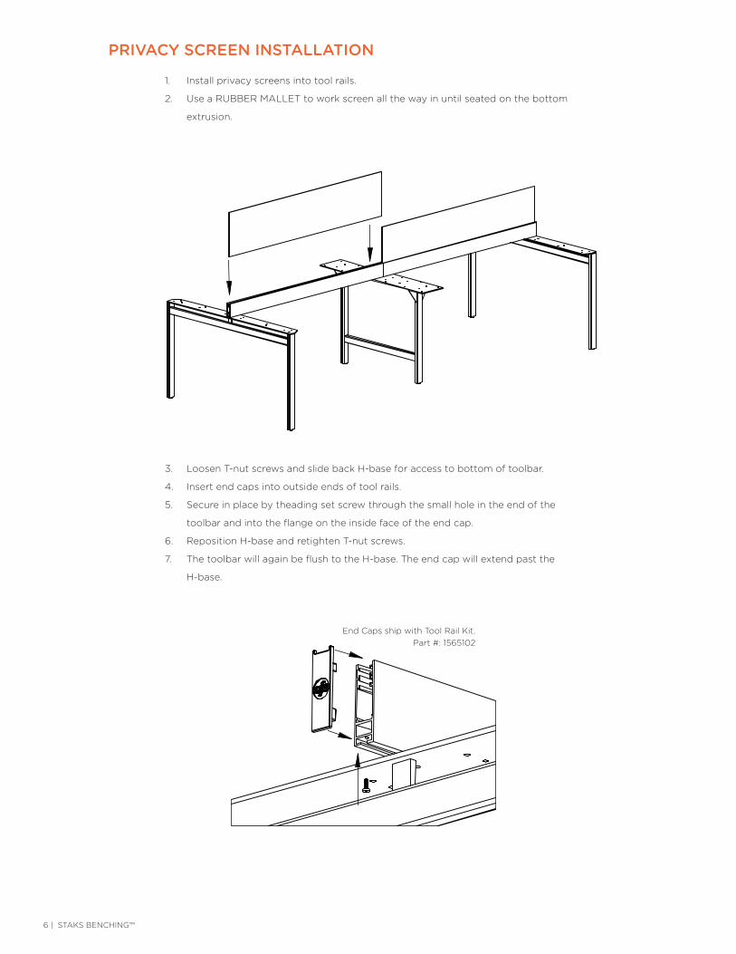
1. Install privacy screens into tool rails.
2. Use a RUBBER MALLET to work screen all the way in until seated on the bottom
extrusion.
PRIVACY SCREEN INSTALLATIONPRIVACY SCREEN INSTALLATION
Install privacy screens into tool rails.•Use a RUBBER MALLET to work screen all the way in until seated•
on the bottom extrusion.
Loosen T-nut screws and slide back H-base for access to bottom• of toolbar.
Insert end caps into outside ends of tool rails.•Secure in place by theading set screw through the small hole in the•
end of the toolbar and into the flange on the inside face of the end cap.Reposition H-base and retighten T-nut screws.•The toolbar will again be flush to the H-base. The end cap will extend•
past the H-base. Page 4
Series: Part #:
PRIVACY SCREEN INSTALLATION
Install privacy screens into tool rails.•Use a RUBBER MALLET to work screen all the way in until seated•
on the bottom extrusion.
Loosen T-nut screws and slide back H-base for access to bottom• of toolbar.
Insert end caps into outside ends of tool rails.•Secure in place by theading set screw through the small hole in the•
end of the toolbar and into the flange on the inside face of the end cap.Reposition H-base and retighten T-nut screws.•The toolbar will again be flush to the H-base. The end cap will extend•
past the H-base. Page 4
Series: Part #:
3. Loosen T-nut screws and slide back H-base for access to bottom of toolbar.
4. Insert end caps into outside ends of tool rails.
5. Secure in place by theading set screw through the small hole in the end of the
toolbar and into the flange on the inside face of the end cap.
6. Reposition H-base and retighten T-nut screws.
7. The toolbar will again be flush to the H-base. The end cap will extend past the
H-base.
End Caps ship with Tool Rail Kit.Part #: 1565102

STAKS BENCHING™ | 7
1. Note: Support rails are used on 22”, 30” and 36” deep tops that are wider than 48”.
2. Position support rail on bottom side of worksurface 6” from user edge in center of
worksurface.
3. Attach with #10 x 5/8” screws.
WORKSURFACE INSTALLATION
6"
FLUSH
WORK SURFACE INSTALLATION
1 1/2"
Position support rail on bottom side of worksurface• 6" from user edge in center of work surface.
Attach with #10 x 5/8" screws.•
Place work surfaces on H-bases with side flush to edge of H-base.•Leave 1 1/2" gap between back edge of work surface and tool bar.•Secure work surfaces to H-bases with #12 x 1" screws. •
Page 5
Series: Part #:
4. Place work surfaces on H-bases with side flush to edge of H-base.
5. Leave 1 1/2” gap between back edge of work surface and tool bar.
6. Secure work surfaces to H-bases with #12 x 1” screws.
1 1/2”
FLUSH
EqualDistance
EqualDistance
6”
1 1/2”
FLUSH
Straightner Rails ship with Tool Rail Kit. Model Numbers:
SPTR66SPTR60SPTR54SPTR48

8 | STAKS BENCHING™
1. Use M6 x 50MM screw to attach top strap to tool bar and stanchion.
TOP STRAP INSTALLATION
2. Secure top strap to bottom of
worksurfaces with eight (8) #8x1”
screws for each top strap.
Top Strap
Top Strap ships with Tool Rail Kit.Part #: 1552075
Part #: 1416448
STAKS BENCHING™ | 9
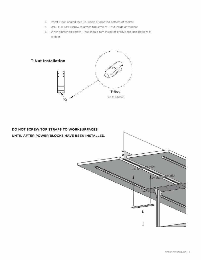
3. Insert T-nut, angled face up, inside of grooved bottom of toolrail.
4. Use M6 x 16MM screw to attach top strap to T-nut inside of tool bar.
5. When tightening screw, T-nut should turn inside of groove and grip bottom of
toolbar.
DO NOT SCREW TOP STRAPS TO WORKSURFACES
UNTIL AFTER POWER BLOCKS HAVE BEEN INSTALLED.
T-Nut Installation
T-NutPart #: 1512929
10 | STAKS BENCHING™
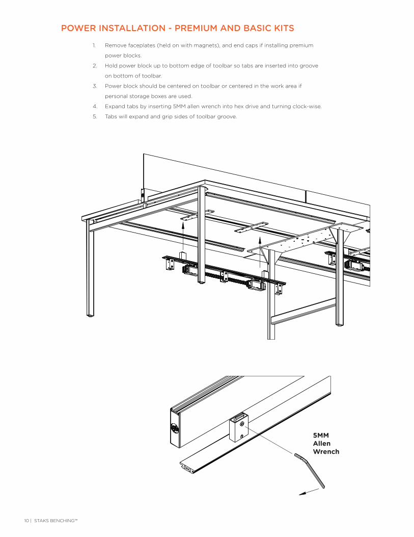
1. Remove faceplates (held on with magnets), and end caps if installing premium
power blocks.
2. Hold power block up to bottom edge of toolbar so tabs are inserted into groove
on bottom of toolbar.
3. Power block should be centered on toolbar or centered in the work area if
personal storage boxes are used.
4. Expand tabs by inserting 5MM allen wrench into hex drive and turning clock-wise.
5. Tabs will expand and grip sides of toolbar groove.
POWER INSTALLATION - PREMIUM AND BASIC KITS
POWER INSTALLATION
Premium and Basic Kits
Remove faceplates (held on with magnets), and end caps if installing• premium power blocks.
Hold power block up to bottom edge of toolbar so tabs are inserted• into groove on bottom of toolbar.
Power block should be centered on toolbar or centered in the work area• if personal storage boxes are used.
Expand tabs by inserting 5MM allen wrench into hex drive and turning• clock-wise.
Tabs will expand and grip sides of toolbar groove.•
5MMallen
wrench
Page 7
Series: Part #:
5MM AllenWrench

STAKS BENCHING™ | 11
6. Plug in one jumper cable between two power blocks.
7. Jumper cable should pass through O-rings.
8. Jumper cable end must be pushed in until it snaps into place.
9. Plug in power in-feed into any receptacle block in the run.
10. Snap in duplex receptacles according to power requirements (usually determined
by an electrician).
11. Place duplex receptacle inside receptacle block with clip pointing down and slide
sideways into terminal until receptacle clicks in place.
12. On premium power blocks, replace end caps and face plates after duplex
receptacles are installed.
O-ring
POWER INSTALLATION
Premium and Basic Kits - con't
Plug in one jumper cable between two power blocks.•Jumper cable should pass through O-rings.•Jumper cable end must be pushed in until it snaps•
into place.Plug in power in-feed into any receptacle block•
in the run.
Page 8
Snap in duplex receptacles according to power requirements• (usually determined by an electrician).
Place duplex receptacle inside receptacle block with clip• pointing down and slide sideways into terminal until receptacle clicks in place.
On premium power blocks, replace end caps and face plates• after duplex receptacles are installed.
Series: Part #:
O-ring
12 | STAKS BENCHING™
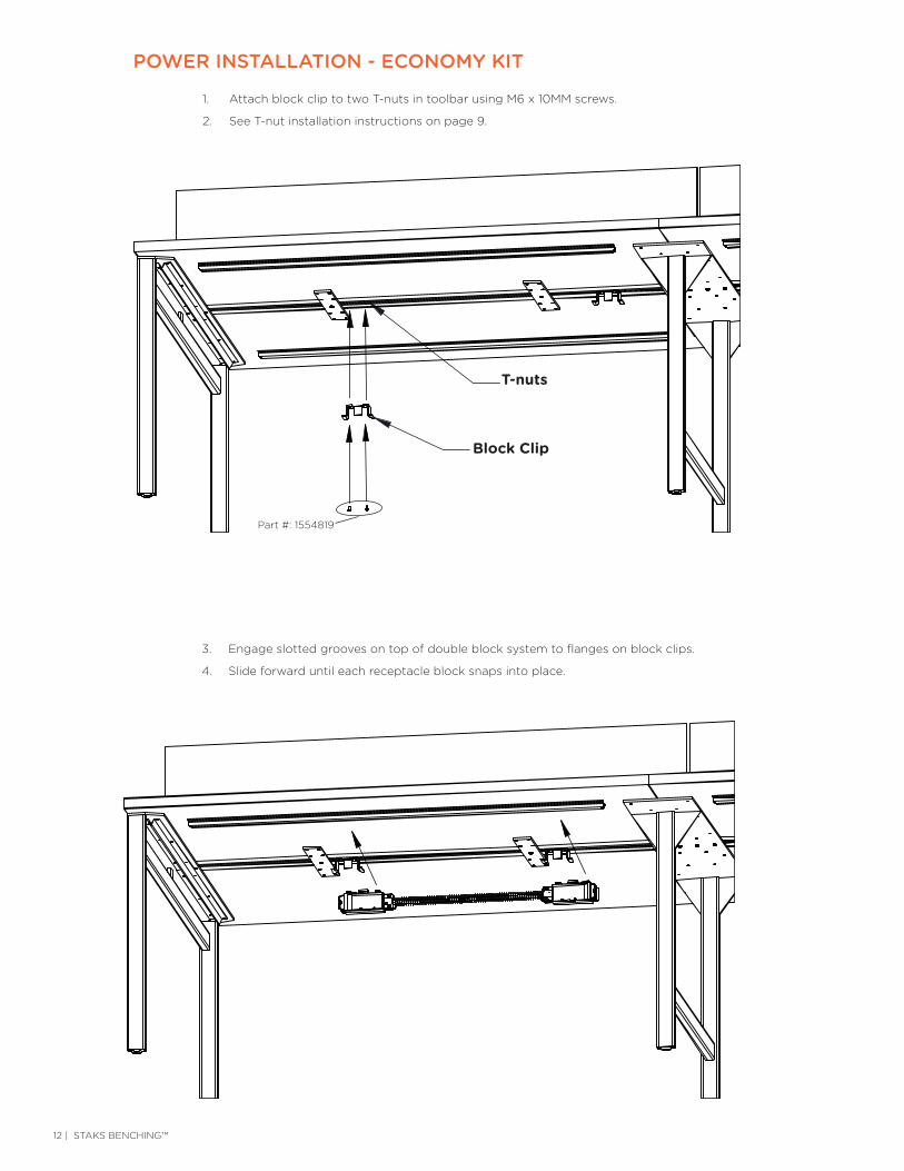
1. Attach block clip to two T-nuts in toolbar using M6 x 10MM screws.
2. See T-nut installation instructions on page 9.
POWER INSTALLATION - ECONOMY KIT
T-nuts
Attach block clip to two T-nuts in toolbar using M6 x 10MM screws.•
See T-nut installation instructions on page 7.•
Block Clip
Engage slotted grooves on top of double block system to flanges• on block clips.
Slide forward until each receptacle block snaps into place.•Page 9
POWER INSTALLATION
Economy Kit
Series: Part #:
3. Engage slotted grooves on top of double block system to flanges on block clips.
4. Slide forward until each receptacle block snaps into place.
T-nuts
Block Clip
Part #: 1554819
STAKS BENCHING™ | 13
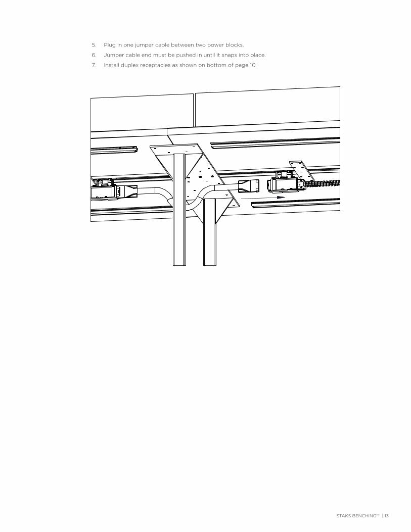
5. Plug in one jumper cable between two power blocks.
6. Jumper cable end must be pushed in until it snaps into place.
7. Install duplex receptacles as shown on bottom of page 10.
Plug in one jumper cable between two power blocks.•
Jumper cable end must be pushed in until it snaps• into place.
Install duplex receptacles as shown on bottom of page 8.•
POWER INSTALLATION
Economy Kit con't
Page 10Series: Part #:

14 | STAKS BENCHING™
Clamp
Assemble basket clamps with two small clamp plates on the top and on• large clamp plate on the bottom.
Clamps should be spaced so they are directly below the O-rings on the• power block.
If the basket is on the end of a bench, the clamps should be shifted, if• possible, so the basket can be mounted towards the center of the bench.
Screw clamps together using four (4) M4 x 10MM screws per clamp.•
Page 11
TOP STRAP INSTALLATION
& CABLE BASKET ASSEMBLY
Secure top strap to bottom of work• surfaces with eight (8) #8 x 1" screws for each top strap.
Series: Part #:
2. Assemble basket clamps with two small clamp plates on the top and on large clamp plate
on the bottom.
3. Clamps should be spaced so they are directly below the O-rings on the power block.
4. If the basket is on the end of a bench, the clamps should be shifted, if possible, so the
basket can be mounted towards the center of the bench.
5. Screw clamps together using four (4) M4 x 10MM screws per clamp.
1. Secure top strap to bottom of work surfaces with eight
(8) #8 x 1” screws for each top strap (HK-31).
TOP STRAP INSTALLATION & CABLE BASKET ASSEMBLY
Clamp
STAKS BENCHING™ | 15
O-ring
Stand off
Bolt
T-nut
Stand off
Bolt
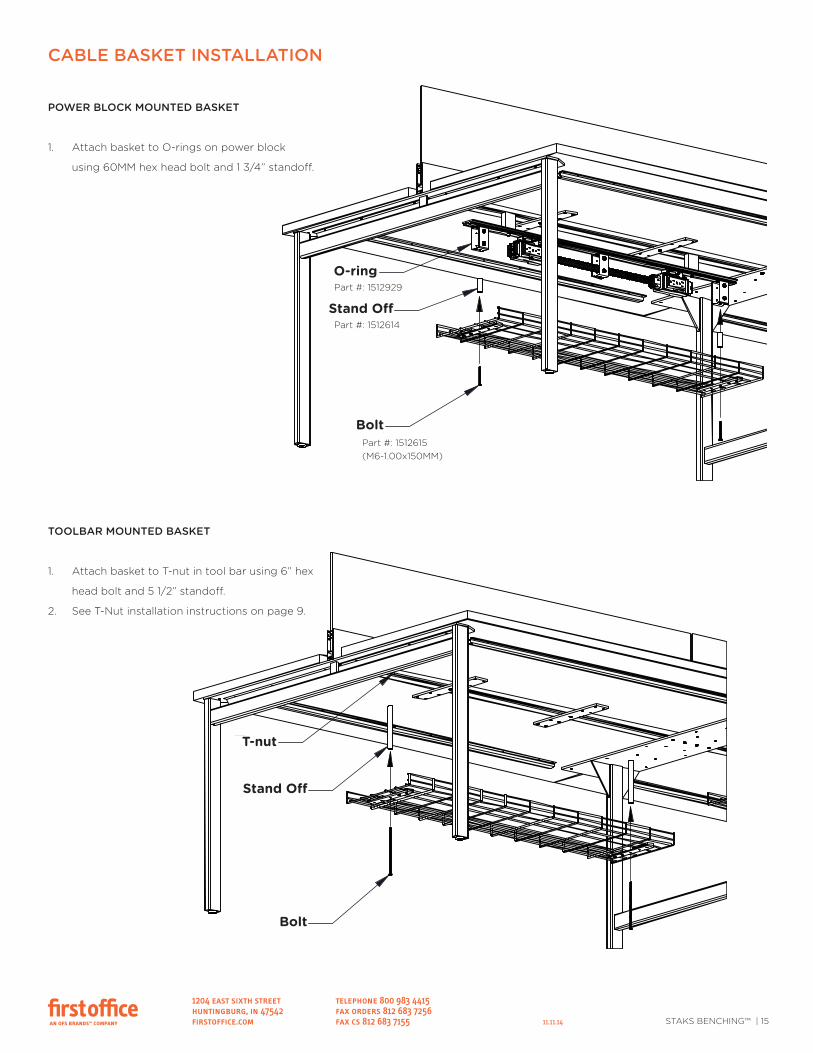
CABLE BASKET INSTALLATION
POWER BLOCK MOUNTED BASKET
TOOLBAR MOUNTED BASKET
Attach basket to O-rings on power blockusing 60MM hex head bolt and 1 3/4"standoff.
Attach basket to T-nut in tool bar using6" hex head bolt and 5 1/2" standoff.
Page 12
See T-nut installation instructionson page 7.
Series: Part #:
CABLE BASKET INSTALLATION
1204 east sixth street telephone 800 983 4415huntingburg, in 47542 fax orders 812 683 7256firstoffice.com fax cs 812 683 7155
O-ring
Stand off
Bolt
T-nut
Stand off
Bolt
CABLE BASKET INSTALLATION
POWER BLOCK MOUNTED BASKET
TOOLBAR MOUNTED BASKET
Attach basket to O-rings on power blockusing 60MM hex head bolt and 1 3/4"standoff.
Attach basket to T-nut in tool bar using6" hex head bolt and 5 1/2" standoff.
Page 12
See T-nut installation instructionson page 7.
Series: Part #:
POWER BLOCK MOUNTED BASKET
1. Attach basket to O-rings on power block
using 60MM hex head bolt and 1 3/4” standoff.
TOOLBAR MOUNTED BASKET
1. Attach basket to T-nut in tool bar using 6” hex
head bolt and 5 1/2” standoff.
2. See T-Nut installation instructions on page 9.
11.11.14
Part #: 1512615(M6-1.00x150MM)
Bolt
Bolt
O-ring
T-nut
Stand Off
Stand Off
Part #: 1512614
Part #: 1512929