Embed Size (px)
Citation preview
2018-01
Assembly Instructions
Contact: HEICO Befestigungstechnik GmbH
Ensestraße 1-9
D-59469 Ense-Niederense
Telefon: +49 (0) 2938/805-0
Telefax: +49 (0) 2938/805-198
E-Mail: [email protected]
Web: www.heico-group.com
HEICO-LOCK® Assembly Instructions
Page 2 / 22
2018-01
1.) Inspection of the type of bolt parts for compatibility with
HEICO-LOCK®
The standard versions of HEICO-LOCK® Wedge Lock Washers (WLW) must only be
combined with bolts with metric ISO coarse thread (DIN 13) or UNC thread (ANSI B1.1)
in the correct nominal sizes. For bolts with fine thread and other thread types, please
contact us before use. Special designs of HEICO-LOCK® WLW might be required.
In unfastened condition, the HEICO-LOCK® WLW must make full-surface contact with
the underside of the bolt head. The shaft or thread diameter and the radius at the
transition zone between bolt head and bolt shaft, as well as the internal diameter of the
HEICO-LOCK® WLW must be taken into account.
Bolts and nuts made of carbon steel (strength categories acc. to DIN EN ISO 898-1:
8.8, 10.9 and 12.9 and < 8.8 or equal) are secured using HEICO-LOCK® WLW made of
heat-treated steel (Mat.No. 1.1191 acc. to EN 10027). Stainless steel bolting
components (e. g. acc. to ISO 3506 A2-70 and A4-80 or equal) are secured using
HEICO-LOCK® stainless steel WLW (Mat.No. 1.4404 acc. to EN 10027).
The use of plain washers in combination with HEICO-LOCK® WLW is generally not
recommended. However, in case that installation of a plain washer is required, it must
be fixed such that it cannot rotate around the bolt axis (i.e. by form-closed contact).
Integration of additional securing elements or securing methods is superfluous (e.g.
gluing of the thread for screw-in joints) and is not recommended.
2.) Visual inspection of the bolting components and the HEICO-LOCK®
Wedge Lock Washers
Are bolt and nut free from dirt?
Can the thread be easily turned in? Any damage at the thread (e.g. kinks, dents) does
not interfere with turning in?
Info: If the HEICO-LOCK® WLW is integrated on a non-fixed plain washer, the plain washer
may turn on the mating material due to vibration so that the securing effect of the
HEICO-LOCK® WLW is eliminated.
Info: The securing function of the HEICO-LOCK® WLW is based on the movement option
between the wedge surfaces of the individual washers and the resulting impairment of the
detachment process due to the wedging effect and/or the increase of tightening force in
case of rotation of the bolt into the direction of detachment (cf. item 8). Additional locking
measure for the thread would lever out the HEICO-LOCK® WLW!
Info: Soiling and damage in the thread may increase the assembly torque and thus affect
the assembly tightening force to be achieved! The same applies for painted threaded holes.
If possible, cover threaded holes before painting.
HEICO-LOCK® Assembly Instructions
Page 3 / 22
2018-01
For initial assembly, unused bolts should be used.
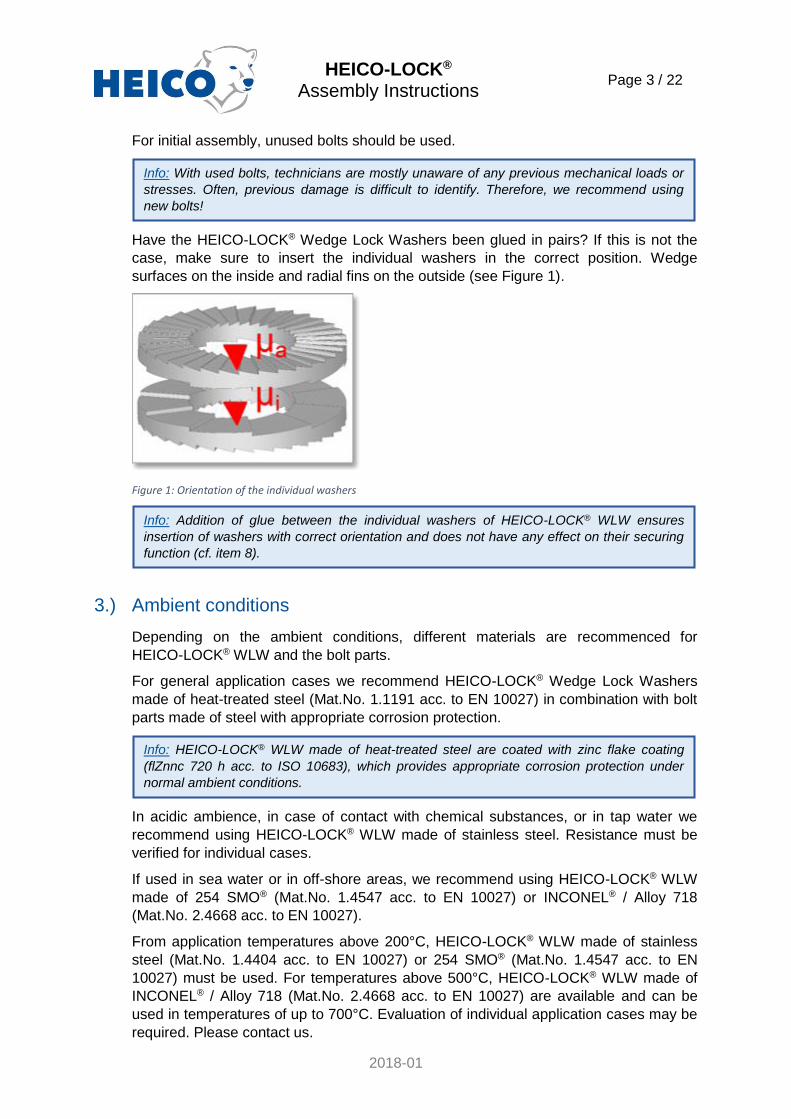
Have the HEICO-LOCK® Wedge Lock Washers been glued in pairs? If this is not the
case, make sure to insert the individual washers in the correct position. Wedge
surfaces on the inside and radial fins on the outside (see Figure 1).
Figure 1: Orientation of the individual washers
3.) Ambient conditions
Depending on the ambient conditions, different materials are recommenced for
HEICO-LOCK® WLW and the bolt parts.
For general application cases we recommend HEICO-LOCK® Wedge Lock Washers
made of heat-treated steel (Mat.No. 1.1191 acc. to EN 10027) in combination with bolt
parts made of steel with appropriate corrosion protection.
In acidic ambience, in case of contact with chemical substances, or in tap water we
recommend using HEICO-LOCK® WLW made of stainless steel. Resistance must be
verified for individual cases.
If used in sea water or in off-shore areas, we recommend using HEICO-LOCK® WLW
made of 254 SMO® (Mat.No. 1.4547 acc. to EN 10027) or INCONEL® / Alloy 718
(Mat.No. 2.4668 acc. to EN 10027).
From application temperatures above 200°C, HEICO-LOCK® WLW made of stainless
steel (Mat.No. 1.4404 acc. to EN 10027) or 254 SMO® (Mat.No. 1.4547 acc. to EN
10027) must be used. For temperatures above 500°C, HEICO-LOCK® WLW made of
INCONEL® / Alloy 718 (Mat.No. 2.4668 acc. to EN 10027) are available and can be
used in temperatures of up to 700°C. Evaluation of individual application cases may be
required. Please contact us.
Info: With used bolts, technicians are mostly unaware of any previous mechanical loads or
stresses. Often, previous damage is difficult to identify. Therefore, we recommend using
new bolts!
Info: Addition of glue between the individual washers of HEICO-LOCK® WLW ensures
insertion of washers with correct orientation and does not have any effect on their securing
function (cf. item 8).
Info: HEICO-LOCK® WLW made of heat-treated steel are coated with zinc flake coating
(flZnnc 720 h acc. to ISO 10683), which provides appropriate corrosion protection under
normal ambient conditions.
HEICO-LOCK® Assembly Instructions
Page 4 / 22
2018-01
With very low ambient temperatures HEICO-LOCK® WLW made of heat-treated steel
(Mat.No. 1.1191 acc. to EN 10027) can be used up to temperatures as low as -40°C.
For even lower application temperatures, we recommend using HEICO-LOCK® WLW
made of stainless steel (Mat.No. 1.4404 acc. to EN 10027), 254 SMO® (Mat.No. 1.4547
acc. to EN 10027), INCONEL® / Alloy 718 (Mat.No. 2.4668 acc. to EN 10027) suitable
up to minimum application temperatures of -200°C. Evaluation of individual application
cases may be required. Please contact us.
4.) Surface condition and surface hardness of fastened parts
In general, the surface of fastened parts, particularly the areas in contact with
HEICO-LOCK® WLW, must be free from coarse soiling and as even and smooth as
possible before assembly.
With great paint or coat thicknesses (> 250 μm) the efficiency of HEICO-LOCK® Wedge
Lock Washers must be verified by experiments. If possible, the bolt joint using HEICO-
LOCK® WLW should be fastened prior to painting or coating.
The surface hardness of the fastened parts must be lower than that of HEICO-LOCK®
Wedge Lock Washers and not exceed a hardness value of max. 460 HV (approx. 46
HRc) for using HEICO-LOCK® WLW out of heat treated steel. For application with
HEICO-LOCK® out of stainless steels the max. surface hardness of the mating parts
should not exceed 520 HV (approx. 50 HRc).
With soft mating material, we recommend using a HEICO-LOCK® WLW with large
contact surface (HLB-XX) in combination with flange bolts and/or flange nuts to reduce
the surface pressure.
5.) Type of bolt joints and geometry of the threaded hole
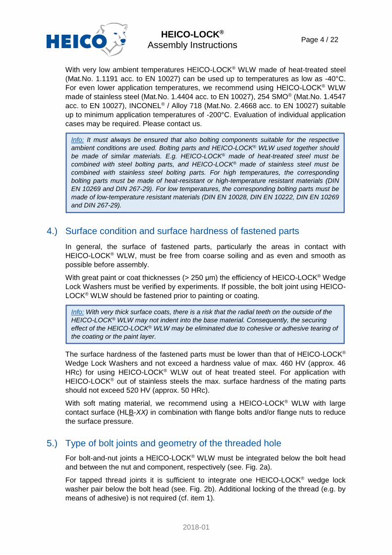
For bolt-and-nut joints a HEICO-LOCK® WLW must be integrated below the bolt head
and between the nut and component, respectively (see. Fig. 2a).
For tapped thread joints it is sufficient to integrate one HEICO-LOCK® wedge lock
washer pair below the bolt head (see. Fig. 2b). Additional locking of the thread (e.g. by
means of adhesive) is not required (cf. item 1).
Info: It must always be ensured that also bolting components suitable for the respective
ambient conditions are used. Bolting parts and HEICO-LOCK® WLW used together should
be made of similar materials. E.g. HEICO-LOCK® made of heat-treated steel must be
combined with steel bolting parts, and HEICO-LOCK® made of stainless steel must be
combined with stainless steel bolting parts. For high temperatures, the corresponding
bolting parts must be made of heat-resistant or high-temperature resistant materials (DIN
EN 10269 and DIN 267-29). For low temperatures, the corresponding bolting parts must be
made of low-temperature resistant materials (DIN EN 10028, DIN EN 10222, DIN EN 10269
and DIN 267-29).
Info: With very thick surface coats, there is a risk that the radial teeth on the outside of the
HEICO-LOCK® WLW may not indent into the base material. Consequently, the securing
effect of the HEICO-LOCK® WLW may be eliminated due to cohesive or adhesive tearing of
the coating or the paint layer.
HEICO-LOCK® Assembly Instructions
Page 5 / 22
2018-01
For threaded rod joints the HEICO-LOCK® WLW must be integrated below the nut(s)
(cf. Fig. 2c).
a) Securing a bolt-and-nut
joint b) Securing a tapped thread
joint c) Securing of a threaded
rod in a threaded hole
Figure 2: Assembly based on the type of bolted joint
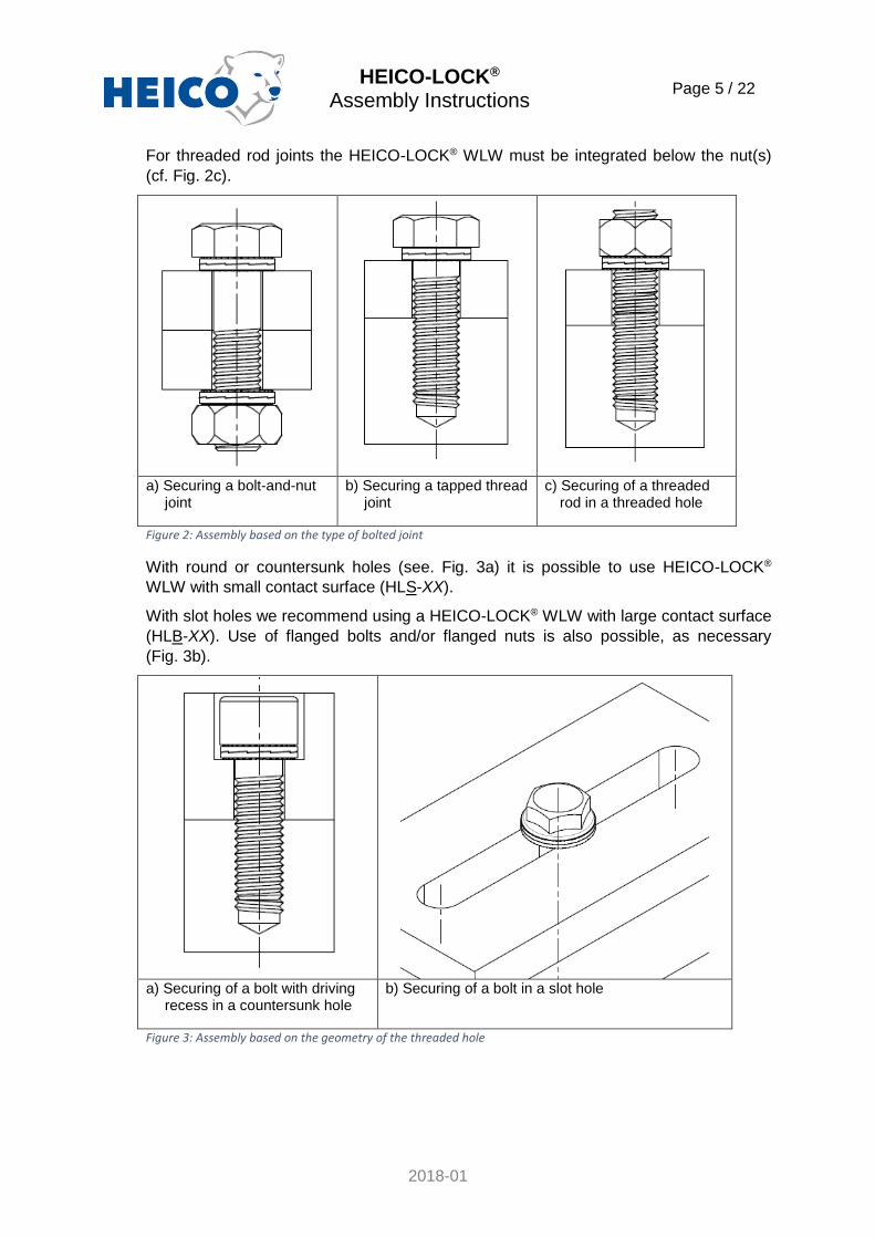
With round or countersunk holes (see. Fig. 3a) it is possible to use HEICO-LOCK®
WLW with small contact surface (HLS-XX).
With slot holes we recommend using a HEICO-LOCK® WLW with large contact surface
(HLB-XX). Use of flanged bolts and/or flanged nuts is also possible, as necessary
(Fig. 3b).
a) Securing of a bolt with driving
recess in a countersunk hole b) Securing of a bolt in a slot hole
Figure 3: Assembly based on the geometry of the threaded hole
HEICO-LOCK® Assembly Instructions
Page 6 / 22
2018-01
6.) Lubrication of the bolted joint
We recommend lubricating the bolted joint at the engaged thread and at the bearing
surfaces of the bolt head and the nut (depending on the side that is tightened) prior to
assembly in order to maintain the assembly tightening torque and/or the assembly
tightening force within a certain range.
7.) Tightening the bolted connection
We urgently request you to use at least one calibrated, adjustable torque wrench for
assembly, in order to ensure correct tightening/fastening of the bolted connection. We
strongly advise against purely “manual” assembly (“feeling the torque”).
If, for assembly of the bolted joint, another tightening force than that recommended by
HEICO in item 9 is required, please contact us. Experimental examination may be
required for individual cases.
The recommended tightening torque values are based on the assumed friction values
under the coating and lubrication conditions specified. In individual cases the tightening
torques required for obtaining the assembly tightening force must be verified by means
of a tightening torque/force test using the original installation set-up.
For assembly of bolt-and-nut joints, one side (either the bolt head or the nut) must
be locked or fixed while the joint is tightened from the opposite side.
Info: Threads with a thick coating may get stuck. Stainless steel threads (e.g. A2 and A4)
are prone to cold welding or “seizure”. Use a suitable lubricant.
Info: A minimum tightening force is required to ensure that the radial teeth on the outer face
make correct form-closed connection with the mating material! The HEICO-LOCK® WLW
meet the criteria of the test regulations according to E-DIN 25201-4, Annex B. According to
these regulations, sufficient securing effect is available at a tightening force of 50% of the
maximum assembly tightening force (acc. to VDI 2230-1, Table A1) with varying transversal
load at a defined amplitude of the transversal shift during 2000 load reversal cycles on a
vibration test stand acc. to DIN 65151, provided that at least 80% of the tightening force is
maintained in the bolted connection at the beginning of the test (50% FM,max).
HEICO-LOCK® Assembly Instructions
Page 7 / 22
2018-01
8.) Functioning of the HEICO-LOCK® Wedge Lock Washers
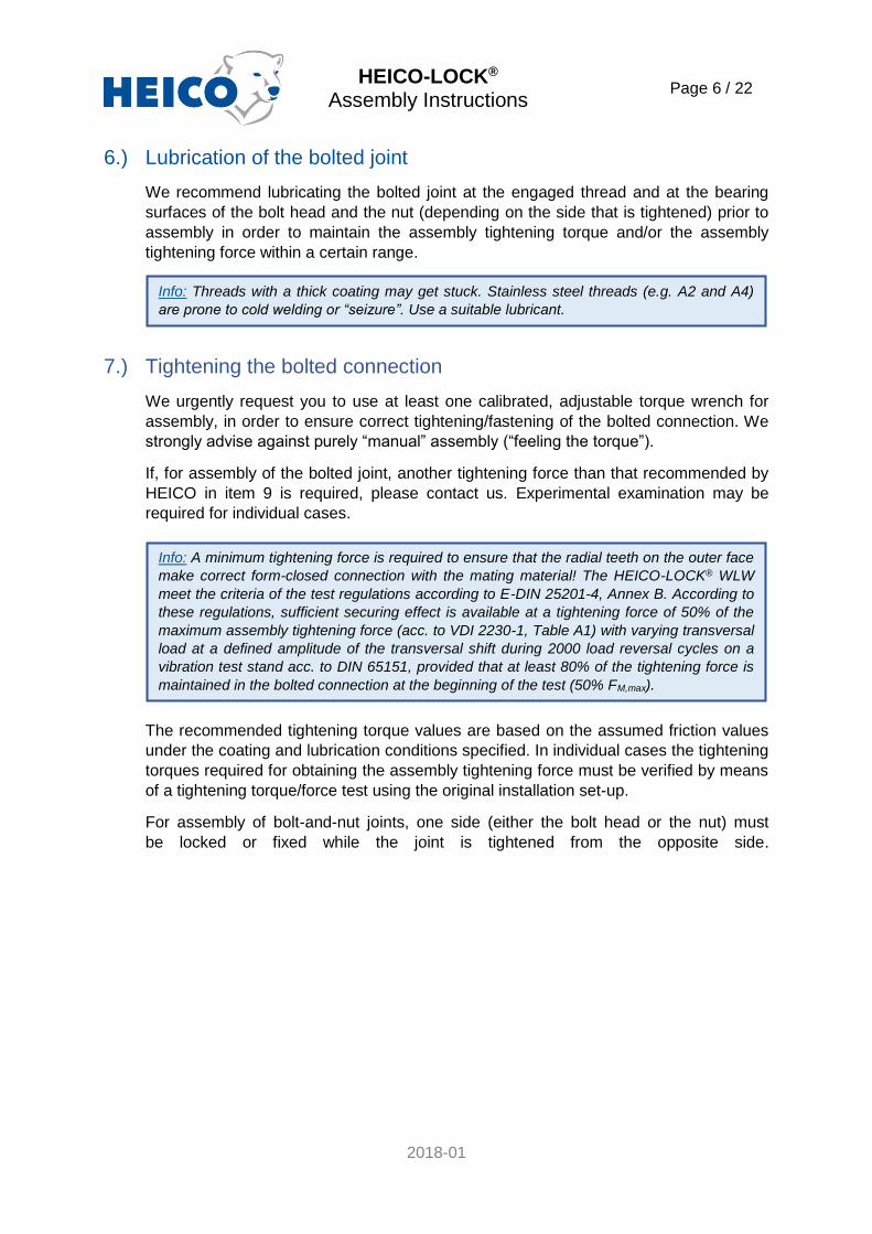
After assembly (taking into account the information given above) the radial teeth on the
outer faces of the HEICO-LOCK® Wedge Lock Washers indent into the mating material
and the bolt head / nut faces (see Fig. 4) and make a form-closed connection due to
the greater surface hardness of the washer.
Figure 4: Indentation of the HEICO-LOCK® WLW due to greater surface hardness
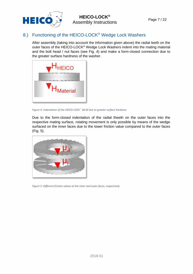
Due to the form-closed indentation of the radial theeth on the outer faces into the
respective mating surface, rotating movement is only possible by means of the wedge
surfaced on the inner faces due to the lower friction value compared to the outer faces
(Fig. 5).
Figure 5: Different friction values at the inner and outer faces, respectively
HEICO-LOCK® Assembly Instructions
Page 8 / 22
2018-01
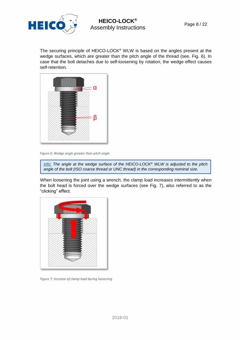
The securing principle of HEICO-LOCK® WLW is based on the angles present at the
wedge surfaces, which are greater than the pitch angle of the thread (see. Fig. 6). In
case that the bolt detaches due to self-loosening by rotation, the wedge effect causes
self-retention.
Figure 6: Wedge angle greater than pitch angle
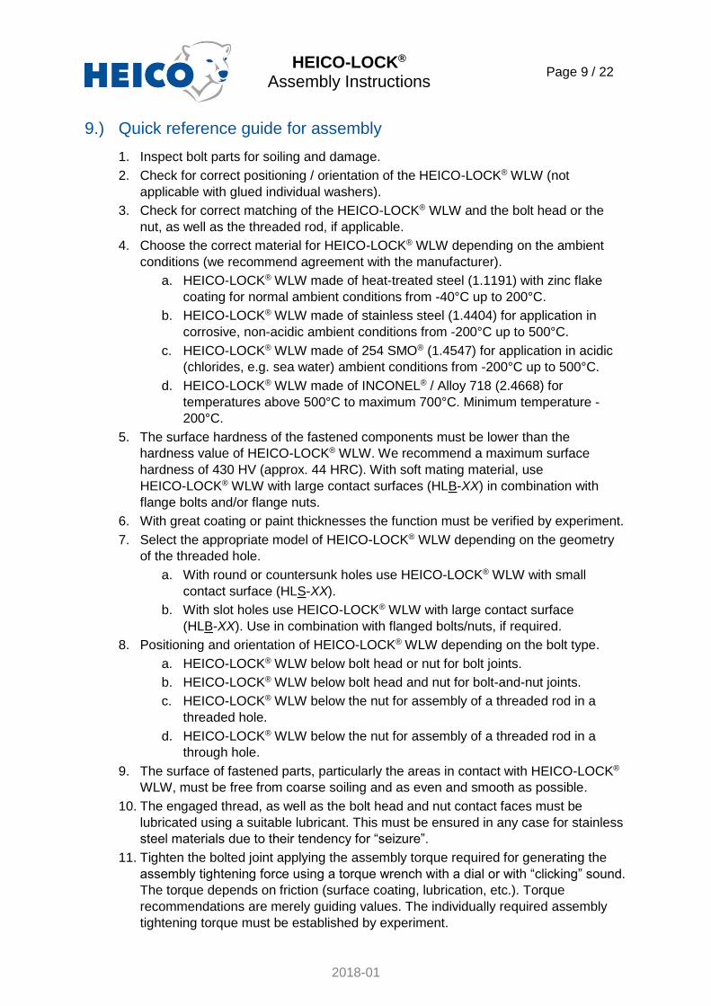
When loosening the joint using a wrench, the clamp load increases intermittently when
the bolt head is forced over the wedge surfaces (see Fig. 7), also referred to as the
“clicking” effect.
Figure 7: Increase of clamp load during loosening
Info: The angle at the wedge surface of the HEICO-LOCK® WLW is adjusted to the pitch
angle of the bolt (ISO coarse thread or UNC thread) in the corresponding nominal size.
HEICO-LOCK® Assembly Instructions
Page 9 / 22
2018-01
9.) Quick reference guide for assembly
1. Inspect bolt parts for soiling and damage.
2. Check for correct positioning / orientation of the HEICO-LOCK® WLW (not
applicable with glued individual washers).
3. Check for correct matching of the HEICO-LOCK® WLW and the bolt head or the
nut, as well as the threaded rod, if applicable.
4. Choose the correct material for HEICO-LOCK® WLW depending on the ambient
conditions (we recommend agreement with the manufacturer).
a. HEICO-LOCK® WLW made of heat-treated steel (1.1191) with zinc flake
coating for normal ambient conditions from -40°C up to 200°C.
b. HEICO-LOCK® WLW made of stainless steel (1.4404) for application in
corrosive, non-acidic ambient conditions from -200°C up to 500°C.
c. HEICO-LOCK® WLW made of 254 SMO® (1.4547) for application in acidic
(chlorides, e.g. sea water) ambient conditions from -200°C up to 500°C.
d. HEICO-LOCK® WLW made of INCONEL® / Alloy 718 (2.4668) for
temperatures above 500°C to maximum 700°C. Minimum temperature -
200°C.
5. The surface hardness of the fastened components must be lower than the
hardness value of HEICO-LOCK® WLW. We recommend a maximum surface
hardness of 430 HV (approx. 44 HRC). With soft mating material, use
HEICO-LOCK® WLW with large contact surfaces (HLB-XX) in combination with
flange bolts and/or flange nuts.
6. With great coating or paint thicknesses the function must be verified by experiment.
7. Select the appropriate model of HEICO-LOCK® WLW depending on the geometry
of the threaded hole.
a. With round or countersunk holes use HEICO-LOCK® WLW with small
contact surface (HLS-XX).
b. With slot holes use HEICO-LOCK® WLW with large contact surface
(HLB-XX). Use in combination with flanged bolts/nuts, if required.
8. Positioning and orientation of HEICO-LOCK® WLW depending on the bolt type.
a. HEICO-LOCK® WLW below bolt head or nut for bolt joints.
b. HEICO-LOCK® WLW below bolt head and nut for bolt-and-nut joints.
c. HEICO-LOCK® WLW below the nut for assembly of a threaded rod in a
threaded hole.
d. HEICO-LOCK® WLW below the nut for assembly of a threaded rod in a
through hole.
9. The surface of fastened parts, particularly the areas in contact with HEICO-LOCK®
WLW, must be free from coarse soiling and as even and smooth as possible.
10. The engaged thread, as well as the bolt head and nut contact faces must be
lubricated using a suitable lubricant. This must be ensured in any case for stainless
steel materials due to their tendency for “seizure”.
11. Tighten the bolted joint applying the assembly torque required for generating the
assembly tightening force using a torque wrench with a dial or with “clicking” sound.
The torque depends on friction (surface coating, lubrication, etc.). Torque
recommendations are merely guiding values. The individually required assembly
tightening torque must be established by experiment.
HEICO-LOCK® Assembly Instructions
Page 10 / 22
2018-01
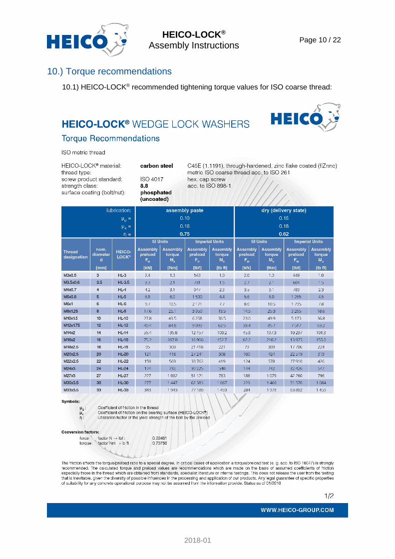
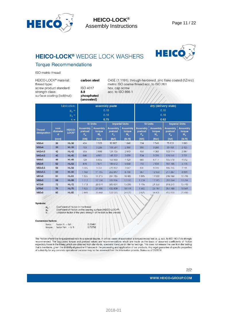
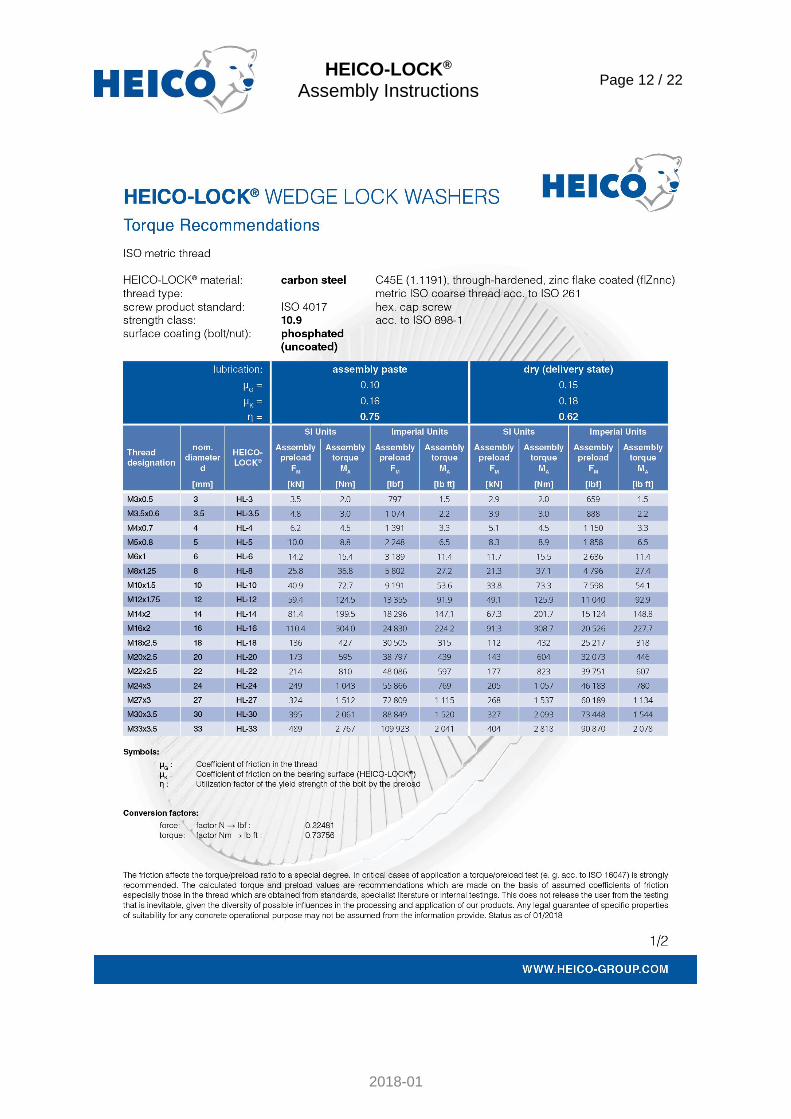
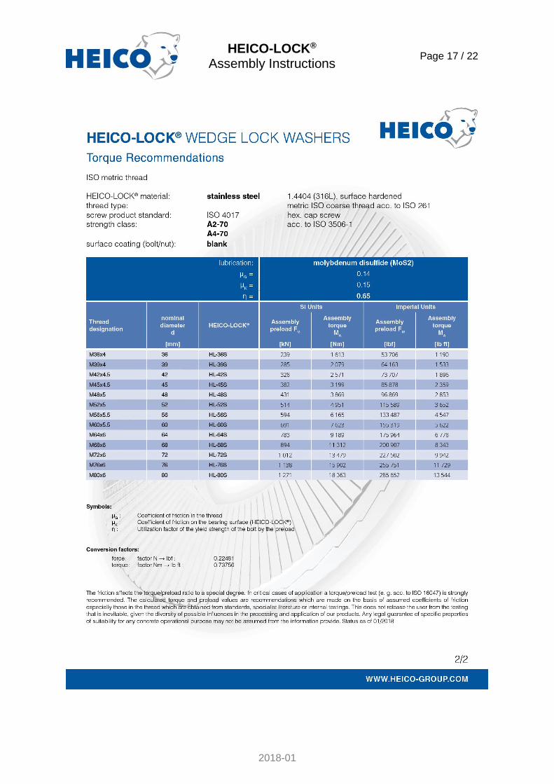
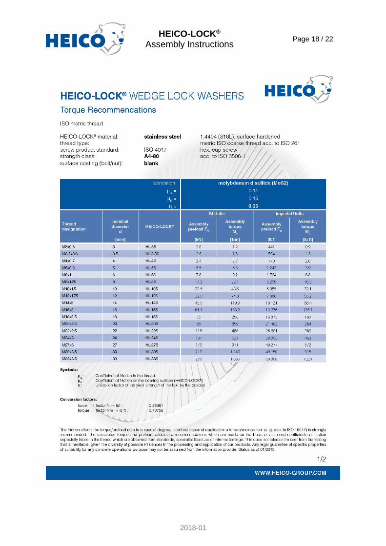
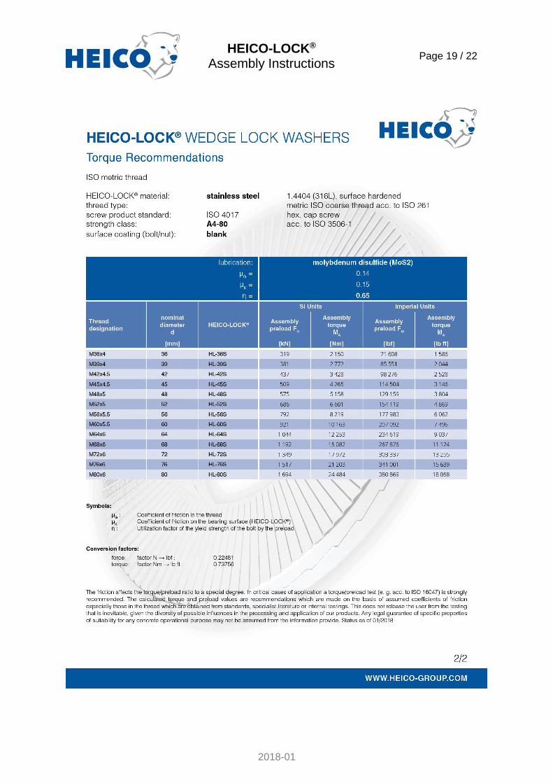
10.) Torque recommendations
10.1) HEICO-LOCK® recommended tightening torque values for ISO coarse thread:
HEICO-LOCK® Assembly Instructions
Page 11 / 22
2018-01
HEICO-LOCK® Assembly Instructions
Page 12 / 22
2018-01

HEICO-LOCK® Assembly Instructions
Page 13 / 22
2018-01

HEICO-LOCK® Assembly Instructions
Page 14 / 22
2018-01

HEICO-LOCK® Assembly Instructions
Page 15 / 22
2018-01

HEICO-LOCK® Assembly Instructions
Page 16 / 22
2018-01
HEICO-LOCK® Assembly Instructions
Page 17 / 22
2018-01
HEICO-LOCK® Assembly Instructions
Page 18 / 22
2018-01
HEICO-LOCK® Assembly Instructions
Page 19 / 22
2018-01
HEICO-LOCK® Assembly Instructions
Page 20 / 22
2018-01
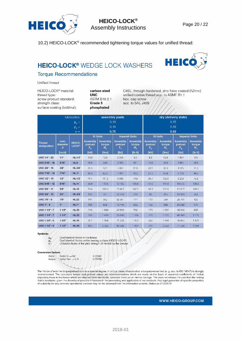
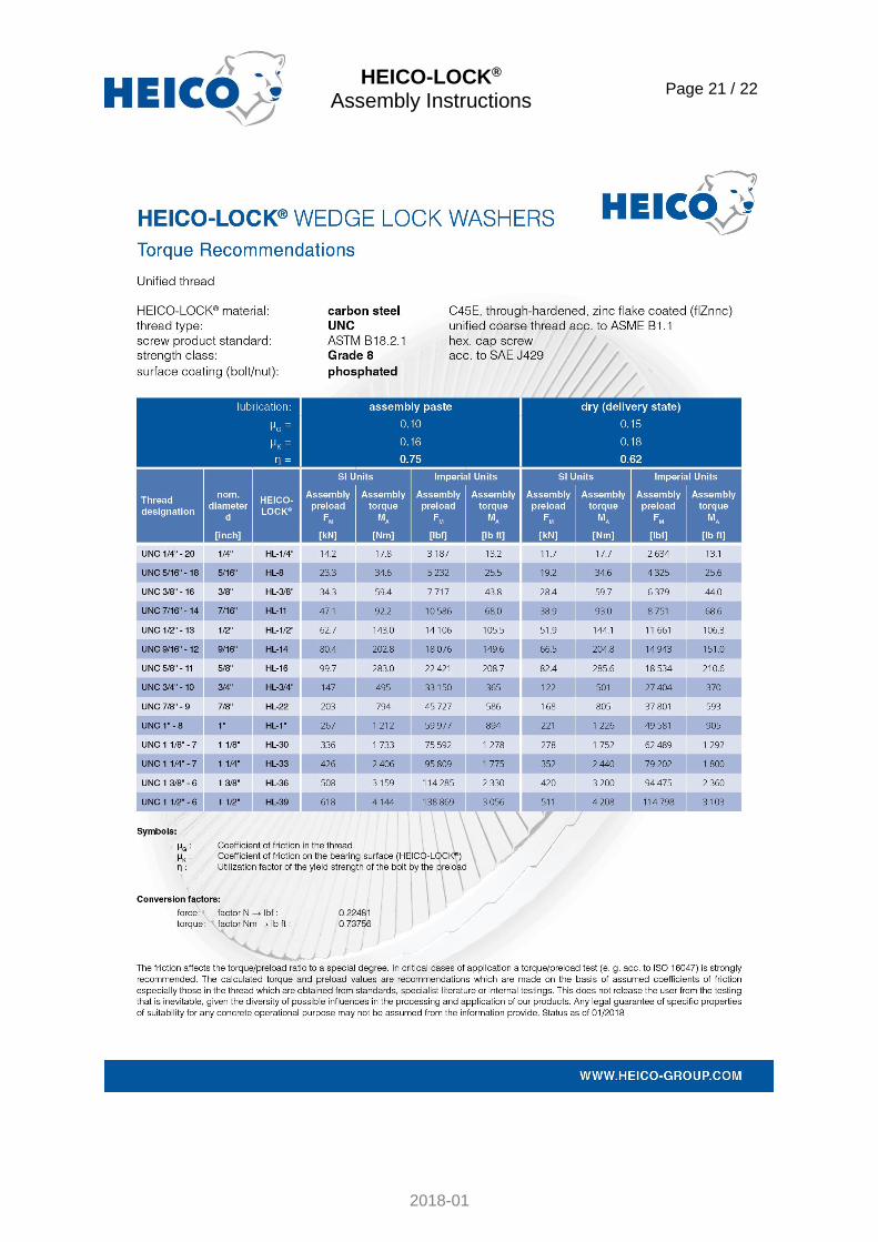
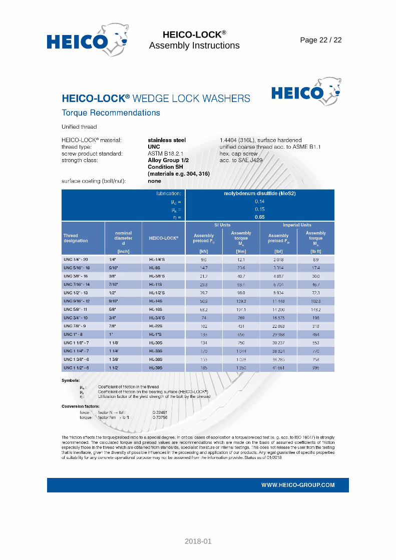
10.2) HEICO-LOCK® recommended tightening torque values for unified thread:
HEICO-LOCK® Assembly Instructions
Page 21 / 22
2018-01
HEICO-LOCK® Assembly Instructions
Page 22 / 22
2018-01