Embed Size (px)
Citation preview
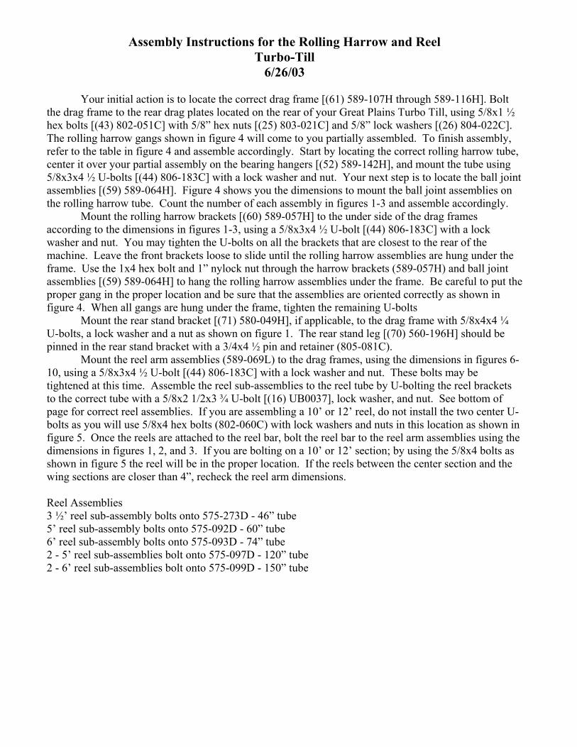
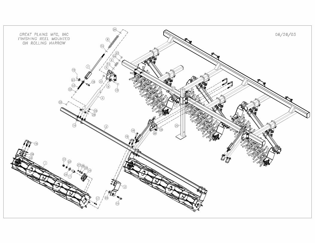
Assembly Instructions for the Rolling Harrow and ReelTurbo-Till
6/26/03
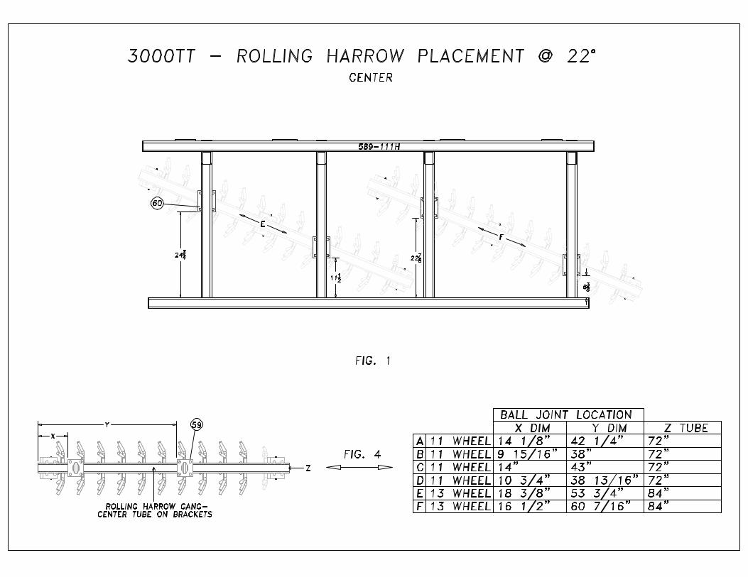
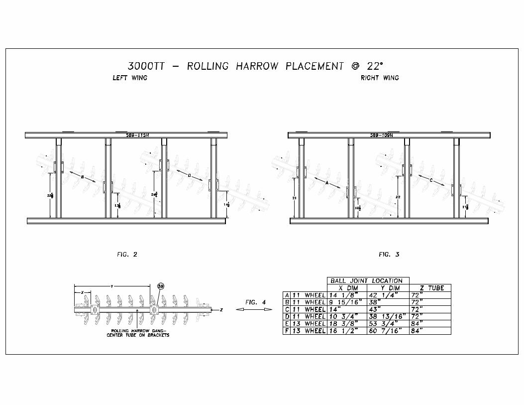
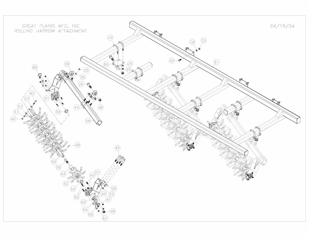
Your initial action is to locate the correct drag frame [(61) 589-107H through 589-116H]. Boltthe drag frame to the rear drag plates located on the rear of your Great Plains Turbo Till, using 5/8x1 ½hex bolts [(43) 802-051C] with 5/8” hex nuts [(25) 803-021C] and 5/8” lock washers [(26) 804-022C].The rolling harrow gangs shown in figure 4 will come to you partially assembled. To finish assembly,refer to the table in figure 4 and assemble accordingly. Start by locating the correct rolling harrow tube,center it over your partial assembly on the bearing hangers [(52) 589-142H], and mount the tube using5/8x3x4 ½ U-bolts [(44) 806-183C] with a lock washer and nut. Your next step is to locate the ball jointassemblies [(59) 589-064H]. Figure 4 shows you the dimensions to mount the ball joint assemblies onthe rolling harrow tube. Count the number of each assembly in figures 1-3 and assemble accordingly.
Mount the rolling harrow brackets [(60) 589-057H] to the under side of the drag framesaccording to the dimensions in figures 1-3, using a 5/8x3x4 ½ U-bolt [(44) 806-183C] with a lockwasher and nut. You may tighten the U-bolts on all the brackets that are closest to the rear of themachine. Leave the front brackets loose to slide until the rolling harrow assemblies are hung under theframe. Use the 1x4 hex bolt and 1” nylock nut through the harrow brackets (589-057H) and ball jointassemblies [(59) 589-064H] to hang the rolling harrow assemblies under the frame. Be careful to put theproper gang in the proper location and be sure that the assemblies are oriented correctly as shown infigure 4. When all gangs are hung under the frame, tighten the remaining U-bolts
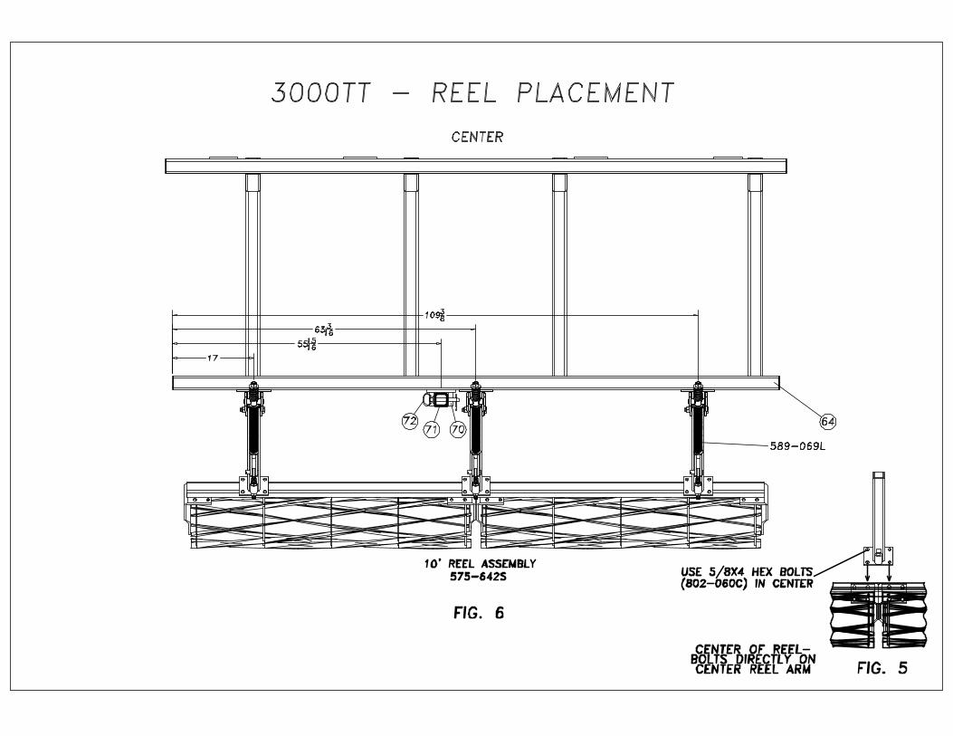
Mount the rear stand bracket [(71) 580-049H], if applicable, to the drag frame with 5/8x4x4 ¼U-bolts, a lock washer and a nut as shown on figure 1. The rear stand leg [(70) 560-196H] should bepinned in the rear stand bracket with a 3/4x4 ½ pin and retainer (805-081C).
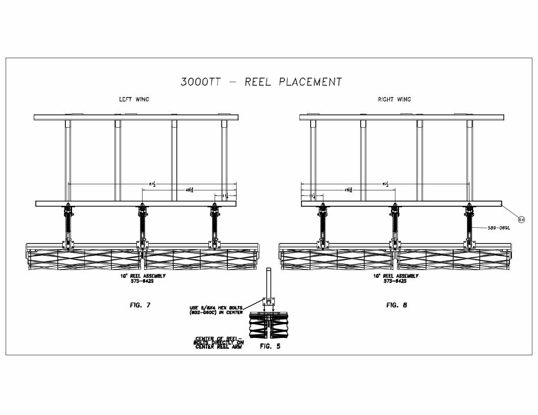
Mount the reel arm assemblies (589-069L) to the drag frames, using the dimensions in figures 6-10, using a 5/8x3x4 ½ U-bolt [(44) 806-183C] with a lock washer and nut. These bolts may betightened at this time. Assemble the reel sub-assemblies to the reel tube by U-bolting the reel bracketsto the correct tube with a 5/8x2 1/2x3 ¾ U-bolt [(16) UB0037], lock washer, and nut. See bottom ofpage for correct reel assemblies. If you are assembling a 10’ or 12’ reel, do not install the two center U-bolts as you will use 5/8x4 hex bolts (802-060C) with lock washers and nuts in this location as shown infigure 5. Once the reels are attached to the reel bar, bolt the reel bar to the reel arm assemblies using thedimensions in figures 1, 2, and 3. If you are bolting on a 10’ or 12’ section; by using the 5/8x4 bolts asshown in figure 5 the reel will be in the proper location. If the reels between the center section and thewing sections are closer than 4”, recheck the reel arm dimensions.
Reel Assemblies3 ½’ reel sub-assembly bolts onto 575-273D - 46” tube5’ reel sub-assembly bolts onto 575-092D - 60” tube6’ reel sub-assembly bolts onto 575-093D - 74” tube2 - 5’ reel sub-assemblies bolt onto 575-097D - 120” tube2 - 6’ reel sub-assemblies bolt onto 575-099D - 150” tube
4/20/2004
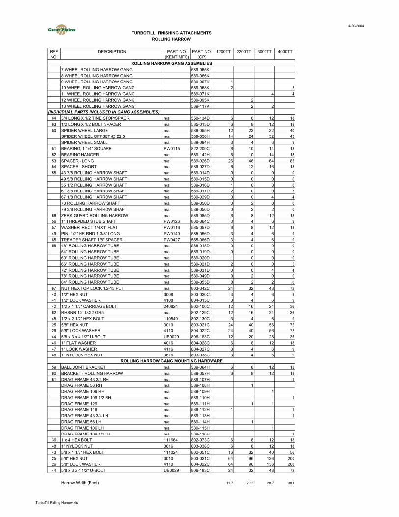
REF DESCRIPTION PART NO. PART NO. 1200TT 2200TT 3000TT 4000TTNO. (KENT MFG) (GP)
7 WHEEL ROLLING HARROW GANG 589-065K8 WHEEL ROLLING HARROW GANG 589-066K9 WHEEL ROLLING HARROW GANG 589-067K 110 WHEEL ROLLING HARROW GANG 589-068K 2 511 WHEEL ROLLING HARROW GANG 589-071K 4 412 WHEEL ROLLING HARROW GANG 589-095K 213 WHEEL ROLLING HARROW GANG 589-117K 2 2
(INDIVIDUAL PARTS INCLUDED IN GANG ASSEMBLIES)64 3/4 LONG X 1/2 TINE STOP/SPACR n/a 550-134D 6 8 12 1863 1/2 LONG X 1/2 BOLT SPACER n/a 585-013D 6 8 12 1850 SPIDER WHEEL LARGE n/a 589-055H 12 22 32 40
SPIDER WHEEL OFFSET @ 22.5 n/a 589-056H 14 24 32 45SPIDER WHEEL SMALL n/a 589-094H 3 4 6 9
51 BEARING, 1 1/4" SQUARE PW0115 822-209C 6 10 14 1852 BEARING HANGER n/a 589-142H 6 10 14 1853 SPACER - LONG n/a 589-026D 26 46 64 8554 SPACER - SHORT n/a 589-027D 6 12 16 1855 43 7/8 ROLLING HARROW SHAFT n/a 589-014D 0 0 0 0
49 5/8 ROLLING HARROW SHAFT n/a 589-015D 0 0 0 055 1/2 ROLLING HARROW SHAFT n/a 589-016D 1 0 0 061 3/8 ROLLING HARROW SHAFT n/a 589-017D 2 0 0 567 1/8 ROLLING HARROW SHAFT n/a 589-029D 0 0 4 473 ROLLING HARROW SHAFT n/a 589-050D 0 2 0 079 3/8 ROLLING HARROW SHAFT n/a 589-056D 0 2 2 0
66 ZERK GUARD ROLLING HARROW n/a 589-085D 6 8 12 1856 1" THREADED STUB SHAFT PW0126 800-364C 3 4 6 957 WASHER, RECT 1/4X1" FLAT PW0116 585-057D 6 8 12 1849 PIN, 1/2" HR RND 1 3/8" LONG PW0140 585-056D 3 4 6 965 TREADER SHAFT 1/8" SPACER PW0427 585-066D 3 4 6 958 48" ROLLING HARROW TUBE n/a 589-018D 0 0 0 0
54" ROLLING HARROW TUBE n/a 589-019D 0 0 0 060" ROLLING HARROW TUBE n/a 589-020D 1 0 0 066" ROLLING HARROW TUBE n/a 589-021D 2 0 0 572" ROLLING HARROW TUBE n/a 589-031D 0 0 4 478" ROLLING HARROW TUBE n/a 589-049D 0 2 0 084" ROLLING HARROW TUBE n/a 589-055D 0 2 2 0
67 NUT HEX TOP LOCK 1/2-13 PLT n/a 803-342C 24 32 48 7240 1/2" HEX NUT 3008 803-020C 3 4 6 941 1/2" LOCK WASHER 4108 804-015C 3 4 6 942 1/2 x 1 1/2" CARRIAGE BOLT 240824 802-106C 12 16 24 3662 RHSNB 1/2-13X2 GR5 n/a 802-129C 12 16 24 3645 1/2 x 2 1/2" HEX BOLT 110540 802-130C 3 4 6 925 5/8" HEX NUT 3010 803-021C 24 40 56 7226 5/8" LOCK WASHER 4110 804-022C 24 40 56 7244 5/8 x 3 x 4 1/2" U-BOLT UB0029 806-183C 12 20 28 3646 1" FLAT WASHER 4016 804-028C 6 8 12 1847 1" LOCK WASHER 4116 804-027C 3 4 6 948 1" NYLOCK HEX NUT 3616 803-038C 3 4 6 9
59 BALL JOINT BRACKET n/a 589-064H 6 8 12 1860 BRACKET - ROLLING HARROW n/a 589-057H 6 8 12 1861 DRAG FRAME 43 3/4 RH n/a 589-107H 1
DRAG FRAME 56 RH n/a 589-108H 1DRAG FRAME 106 RH n/a 589-109H 1DRAG FRAME 109 1/2 RH n/a 589-110H 1DRAG FRAME 129 n/a 589-111H 1 1DRAG FRAME 149 n/a 589-112H 1 1DRAG FRAME 43 3/4 LH n/a 589-113H 1DRAG FRAME 56 LH n/a 589-114H 1DRAG FRAME 106 LH n/a 589-115H 1DRAG FRAME 109 1/2 LH n/a 589-116H 1
36 1 x 4 HEX BOLT 111664 802-073C 6 8 12 1848 1" NYLOCK NUT 3616 803-038C 6 8 12 1843 5/8 x 1 1/2" HEX BOLT 111024 802-051C 16 32 40 5625 5/8" HEX NUT 3010 803-021C 64 96 136 20026 5/8" LOCK WASHER 4110 804-022C 64 96 136 20044 5/8 x 3 x 4 1/2" U-BOLT UB0029 806-183C 24 32 48 72
Harrow Width (Feet) 11.7 20.6 28.7 38.1
TURBOTILL FINISHING ATTACHMENTSROLLING HARROW
ROLLING HARROW GANG ASSEMBLIES
ROLLING HARROW GANG MOUNTING HARDWARE
TurboTill Rolling Harrow.xls
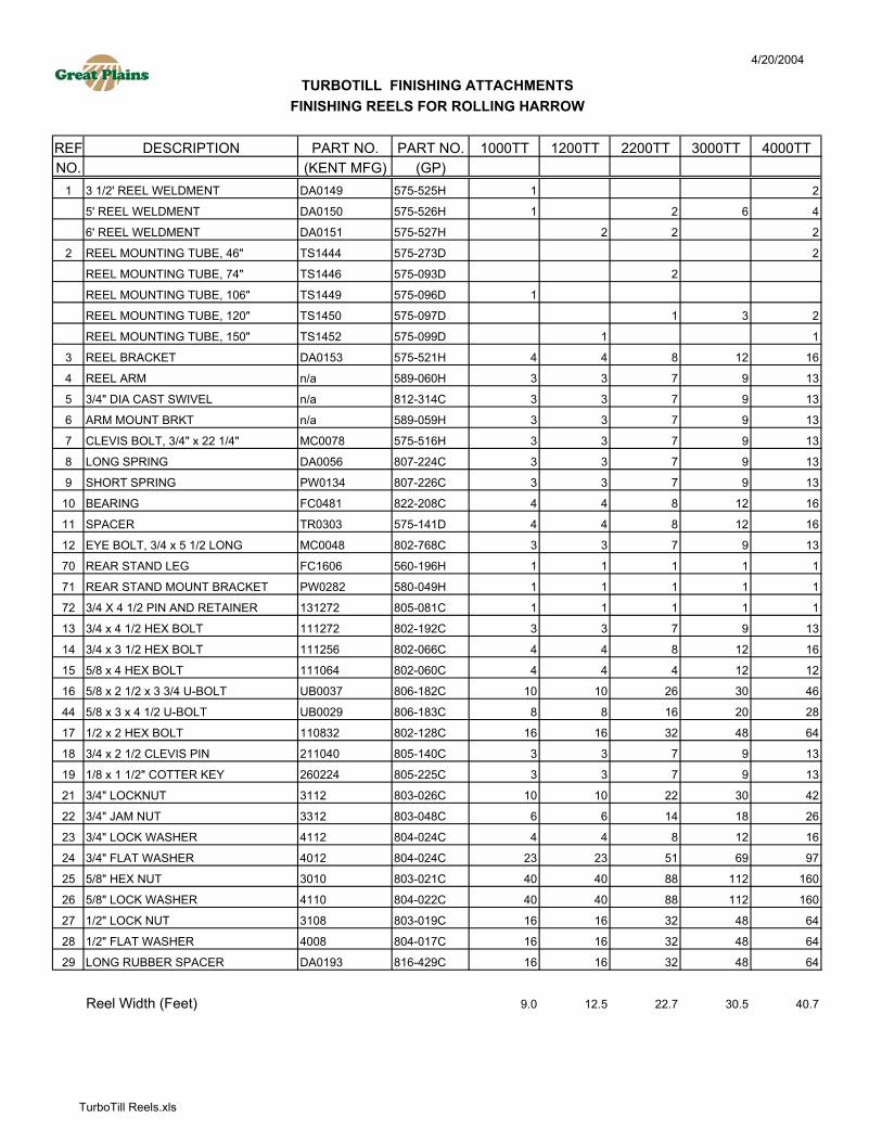
4/20/2004
REF DESCRIPTION PART NO. PART NO. 1000TT 1200TT 2200TT 3000TT 4000TTNO. (KENT MFG) (GP)
1 3 1/2' REEL WELDMENT DA0149 575-525H 1 2
5' REEL WELDMENT DA0150 575-526H 1 2 6 4
6' REEL WELDMENT DA0151 575-527H 2 2 2
2 REEL MOUNTING TUBE, 46" TS1444 575-273D 2
REEL MOUNTING TUBE, 74" TS1446 575-093D 2
REEL MOUNTING TUBE, 106" TS1449 575-096D 1
REEL MOUNTING TUBE, 120" TS1450 575-097D 1 3 2
REEL MOUNTING TUBE, 150" TS1452 575-099D 1 1
3 REEL BRACKET DA0153 575-521H 4 4 8 12 16
4 REEL ARM n/a 589-060H 3 3 7 9 13
5 3/4" DIA CAST SWIVEL n/a 812-314C 3 3 7 9 13
6 ARM MOUNT BRKT n/a 589-059H 3 3 7 9 13
7 CLEVIS BOLT, 3/4" x 22 1/4" MC0078 575-516H 3 3 7 9 13
8 LONG SPRING DA0056 807-224C 3 3 7 9 13
9 SHORT SPRING PW0134 807-226C 3 3 7 9 13
10 BEARING FC0481 822-208C 4 4 8 12 16
11 SPACER TR0303 575-141D 4 4 8 12 16
12 EYE BOLT, 3/4 x 5 1/2 LONG MC0048 802-768C 3 3 7 9 13
70 REAR STAND LEG FC1606 560-196H 1 1 1 1 1
71 REAR STAND MOUNT BRACKET PW0282 580-049H 1 1 1 1 1
72 3/4 X 4 1/2 PIN AND RETAINER 131272 805-081C 1 1 1 1 1
13 3/4 x 4 1/2 HEX BOLT 111272 802-192C 3 3 7 9 13
14 3/4 x 3 1/2 HEX BOLT 111256 802-066C 4 4 8 12 16
15 5/8 x 4 HEX BOLT 111064 802-060C 4 4 4 12 12
16 5/8 x 2 1/2 x 3 3/4 U-BOLT UB0037 806-182C 10 10 26 30 46
44 5/8 x 3 x 4 1/2 U-BOLT UB0029 806-183C 8 8 16 20 28
17 1/2 x 2 HEX BOLT 110832 802-128C 16 16 32 48 64
18 3/4 x 2 1/2 CLEVIS PIN 211040 805-140C 3 3 7 9 13
19 1/8 x 1 1/2" COTTER KEY 260224 805-225C 3 3 7 9 13
21 3/4" LOCKNUT 3112 803-026C 10 10 22 30 42
22 3/4" JAM NUT 3312 803-048C 6 6 14 18 26
23 3/4" LOCK WASHER 4112 804-024C 4 4 8 12 16
24 3/4" FLAT WASHER 4012 804-024C 23 23 51 69 97
25 5/8" HEX NUT 3010 803-021C 40 40 88 112 160
26 5/8" LOCK WASHER 4110 804-022C 40 40 88 112 160
27 1/2" LOCK NUT 3108 803-019C 16 16 32 48 64
28 1/2" FLAT WASHER 4008 804-017C 16 16 32 48 64
29 LONG RUBBER SPACER DA0193 816-429C 16 16 32 48 64
Reel Width (Feet) 9.0 12.5 22.7 30.5 40.7
TURBOTILL FINISHING ATTACHMENTSFINISHING REELS FOR ROLLING HARROW
TurboTill Reels.xls