Embed Size (px)
Citation preview
Assembly instructions
VOSS quick connect system 271
The benchmark for customized connection solutions in thermal management

Assembly instructions VOSS quick connect system 271, page 2 of 14
A. Important notices
Please observe before using the quick connect systems
VOSS quick connect system 271 is suitable for the fir-tree connection of cooling
lines, especially for battery temperature control.
The temperature range is from -40 °C to +85 °C
The maximum operating pressure is 2 bar.
You can use quick connect system 271 for different requirements upon request.
Please observe during assembly of the quick connect systems The assembly of the quick connect system must be conducted by professional
mechanics subject to these assembly instructions.
Incorrectly assembled connections can result in leakage or failure of the system.
VOSS quick connect system 271 may only be used with connections and tubes described
in chapter B (“Components and material“).
Before connecting both sides, components must be checked. They have to be clean
and must not show any signs of damage.
System properties
VOSS quick connect system 271 is a plastic plug, optionally available with Double Lock
(DL), for the connection of cooling lines (PA tubes), especially for components with
recessed ports, or with material for profiled bores.
Connecting port according to VOSS standard
Available sizes: S6, S10, S14, S18
VOSS quick connect system 271 DL is available with a secondary lock (Double Lock)
as additional safety device as well as visual and haptical connection indications.
The connection of VOSS quick connect system 271 is made by plugging the plug in
the connection port. The arms of the locking element of the plug snap into the holes of
the connection port. The complete connection is visually and haptically marked by
snap-in.
!
!
!
!
Assembly instructions VOSS quick connect system 271, page 3 of 14
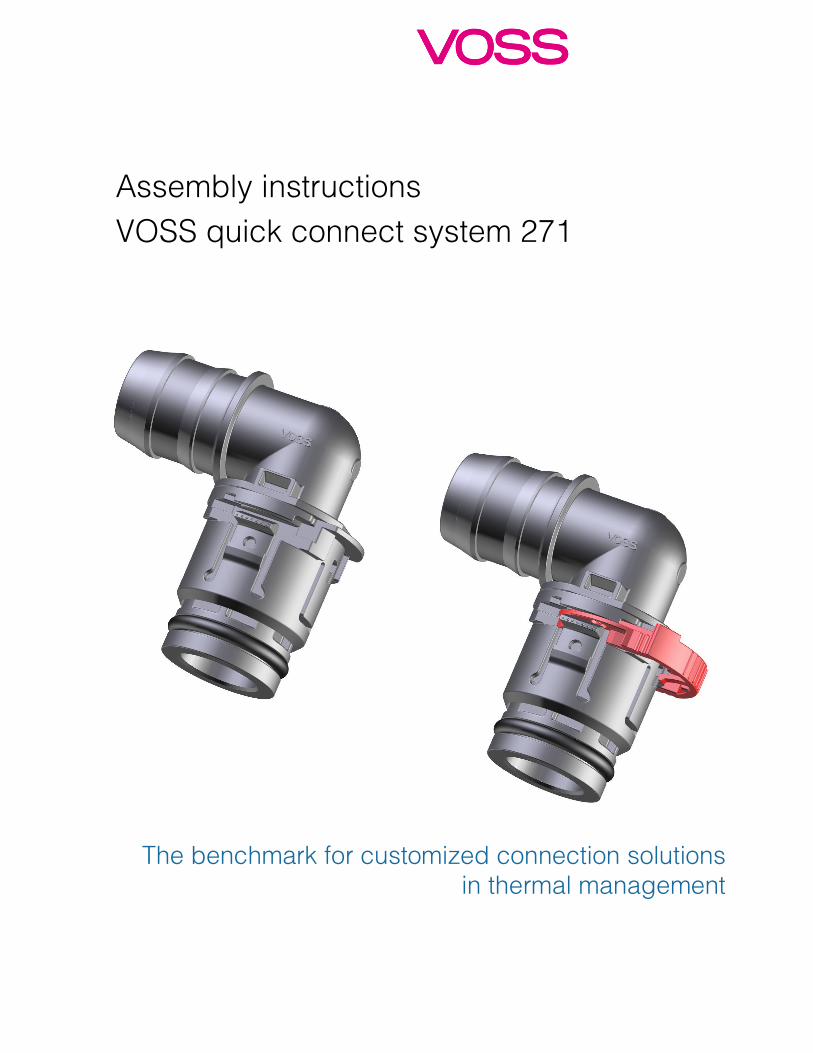
B. Components and material 1. Tube dimensions and nominal sizes
Quick connect system Quick connect system Quick connect system Quick connect system 271271271271
PA tube Available alignments: 90°/180°
Inner diameter [mm]
Outer diameter x tube width [mm]
S6 S10 S14 S18
6 8x1
8 10x1
10 13x1
11 13x1,5
12 15x1,5
14 17x1,5
18 21x1,5
Further connection possibilities (e.g. hose), tube sizes or alignment possible on customer requests.
Assembly instructions VOSS quick connect system 271, page 4 of 14
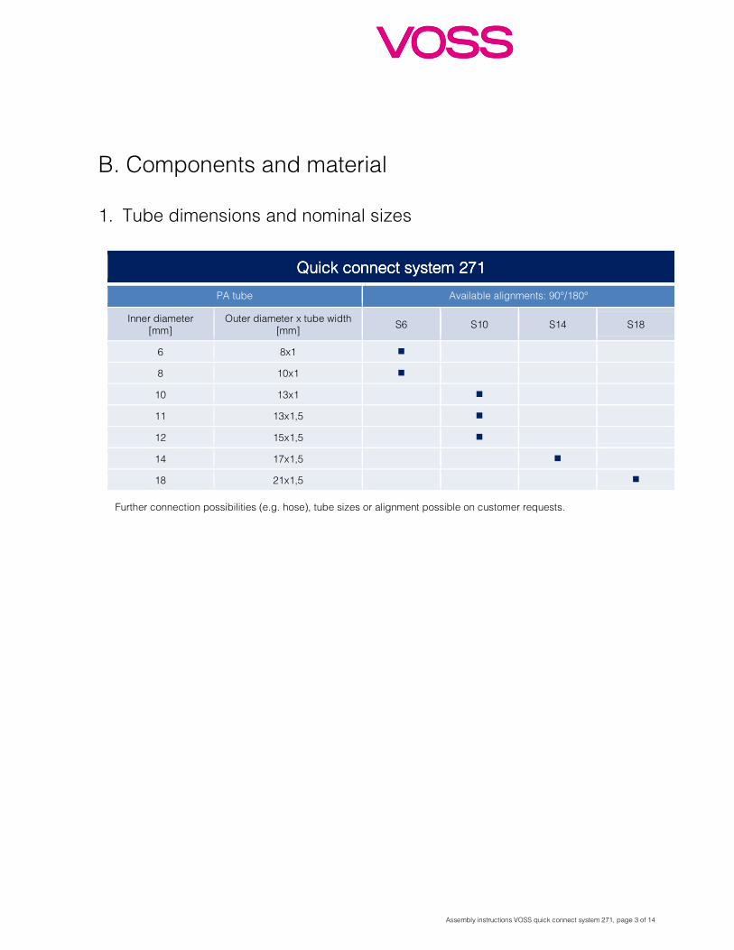
2. The quick connect systems 271 Fig. 1: Components of quick connect system 271 and 271 DL
Connecting port
Fig. 2: Cross section of connecting port according to VOSS standard
Available alignments
Fig. 3: Straight and elbow plug 271, Fig. 4: Straight and elbow plug 271
DL,
locking element can be rotated 90° locking element & Double Lock can be rotated 90°
Body
Double Lock
O-ring
Locking element
Assembly instructions VOSS quick connect system 271, page 5 of 14
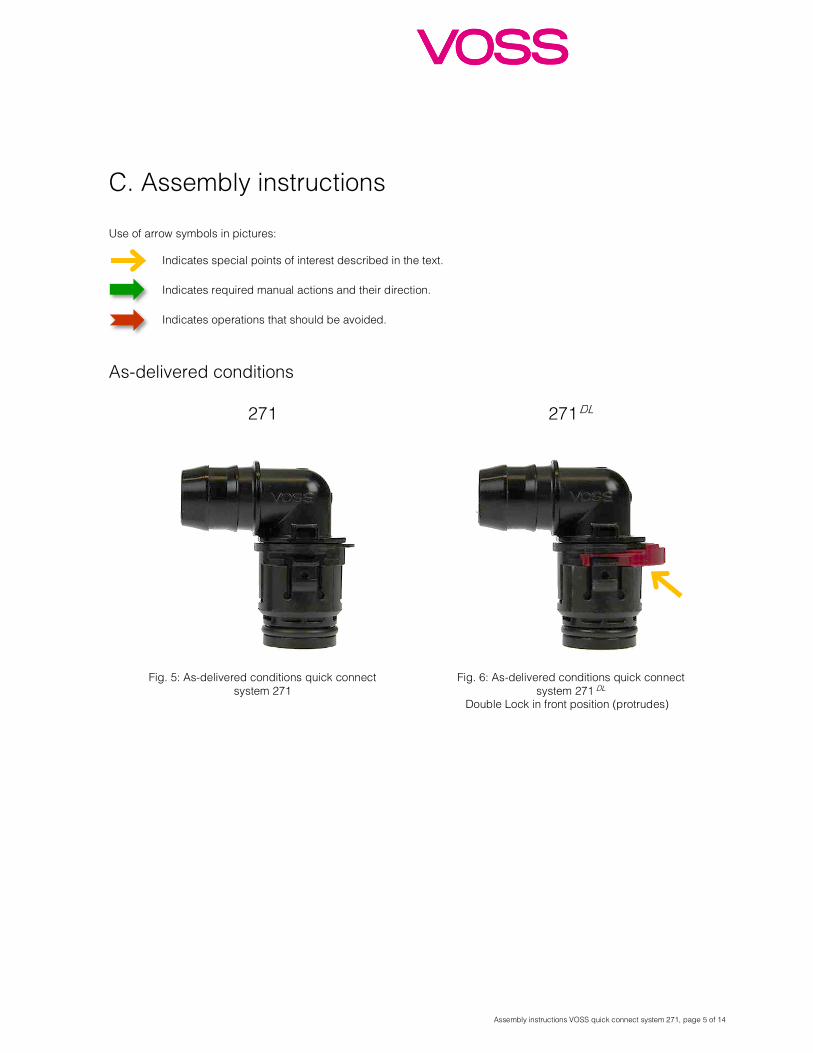
C. Assembly instructions
Use of arrow symbols in pictures: Indicates special points of interest described in the text.
Indicates required manual actions and their direction.
Indicates operations that should be avoided.
As-delivered conditions
271
271
DL
Fig. 5: As-delivered conditions quick connect system 271
Fig. 6: As-delivered conditions quick connect system 271 DL
Double Lock in front position (protrudes)
Assembly instructions VOSS quick connect system 271, page 6 of 14
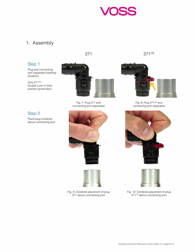
1. Assembly 271 271
DL Step 1 Plug and connecting port separated (starting situation) Only 271
DL: Double Lock in front position (protrudes)
Fig. 7: Plug 271 and connecting port separated
Fig. 8: Plug 271 DL and
connecting port separated
Step 2 Place plug centered above connecting port
Fig. 9: Centered placement of plug 271 above connecting port
Fig. 10: Centered placement of plug 271
DL above connecting port
Assembly instructions VOSS quick connect system 271, page 7 of 14
271 271 DL
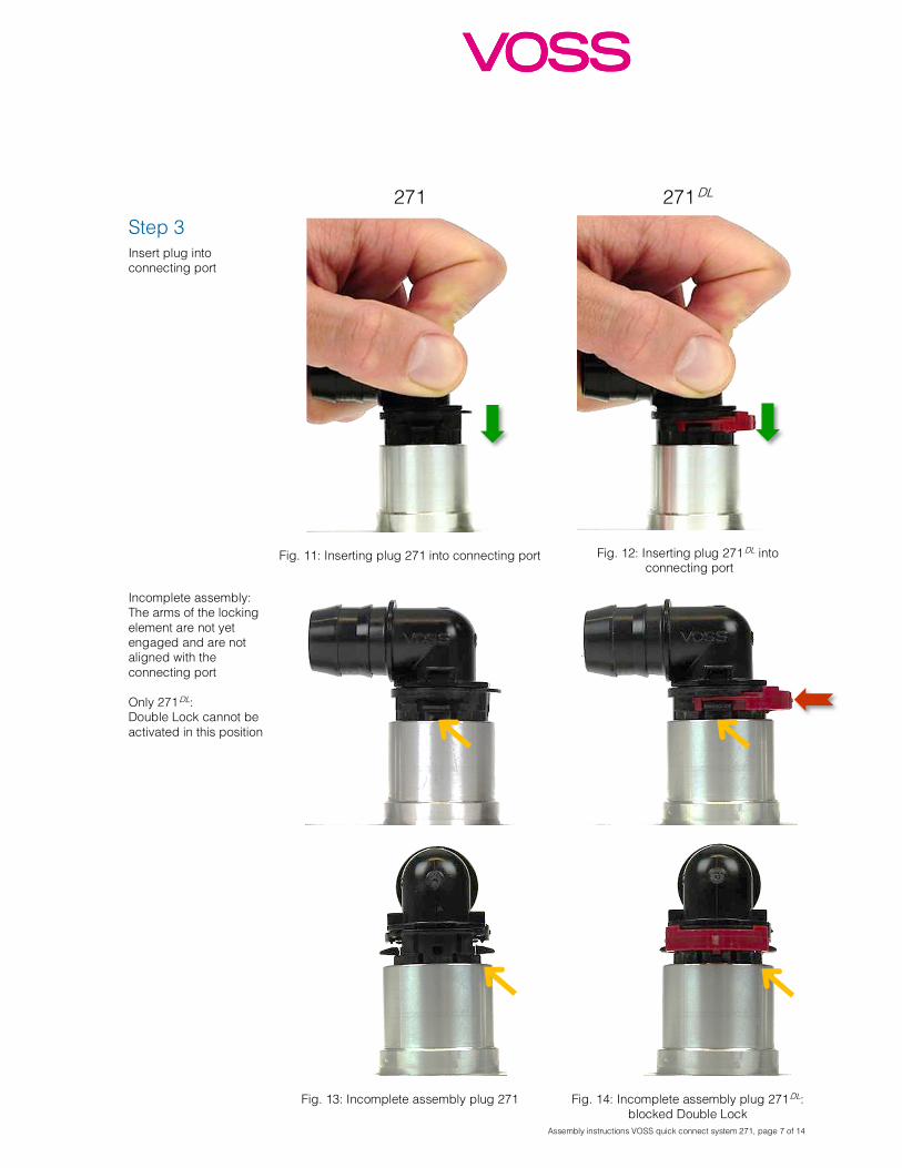
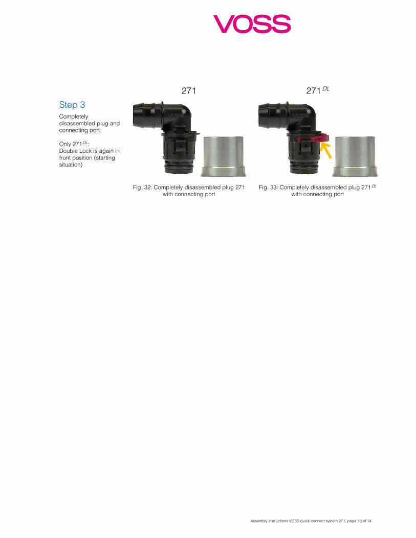
Step 3
Fig. 11: Inserting plug 271 into connecting port
Fig. 12: Inserting plug 271 DL into
connecting port
Insert plug into connecting port
Incomplete assembly: The arms of the locking element are not yet engaged and are not aligned with the connecting port Only 271
DL: Double Lock cannot be activated in this position
Fig. 13: Incomplete assembly plug 271
Fig. 14: Incomplete assembly plug 271 DL:
blocked Double Lock
Assembly instructions VOSS quick connect system 271, page 8 of 14
271 271 DL
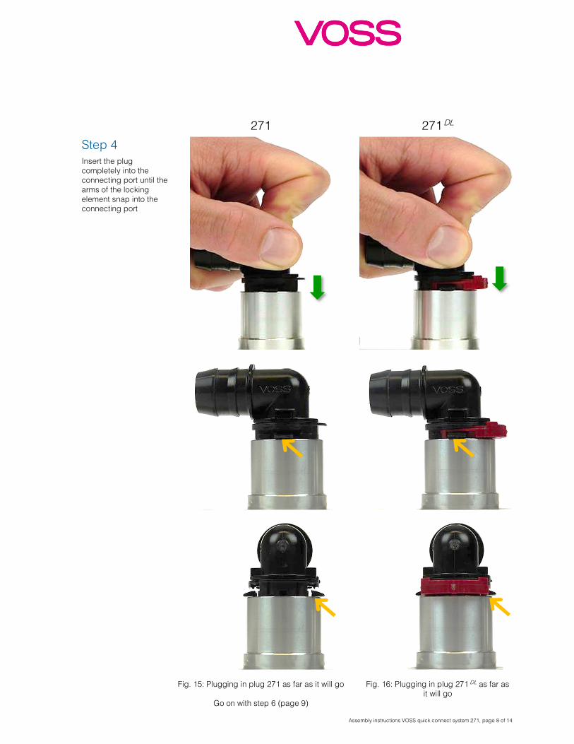
Step 4 Insert the plug completely into the connecting port until the arms of the locking element snap into the connecting port
Fig. 15: Plugging in plug 271 as far as it will go
Go on with step 6 (page 9)
Fig. 16: Plugging in plug 271 DL as far as
it will go
Assembly instructions VOSS quick connect system 271, page 9 of 14
271 271 DL
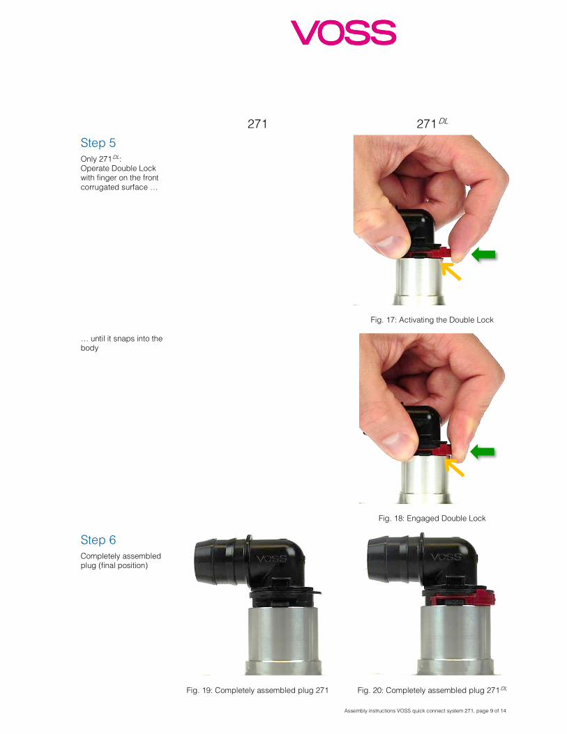
Step 5 Only 271
DL: Operate Double Lock with finger on the front corrugated surface …
Fig. 17: Activating the Double Lock
… until it snaps into the body
Fig. 18: Engaged Double Lock
Step 6 Completely assembled plug (final position)
Fig. 19: Completely assembled plug 271
Fig. 20: Completely assembled plug 271 DL
Assembly instructions VOSS quick connect system 271, page 10 of 14
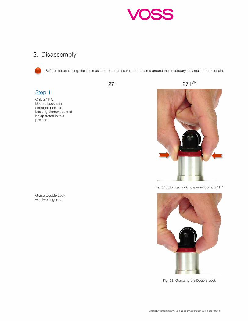
2. Disassembly
Before disconnecting, the line must be free of pressure, and the area around the secondary lock must be free of dirt.
271 271 DL
Step 1 Only 271
DL: Double Lock is in engaged position. Locking element cannot be operated in this position
Fig. 21: Blocked locking element plug 271 DL
Grasp Double Lock with two fingers …
Fig. 22: Grasping the Double Lock
!
Assembly instructions VOSS quick connect system 271, page 11 of 14
271 271 DL
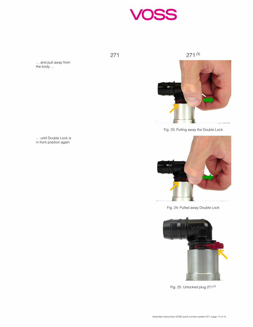
… and pull away from the body …
Fig. 23: Pulling away the Double Lock
… until Double Lock is in front position again
Fig. 24: Pulled away Double Lock
Fig. 25: Unlocked plug 271 DL
Assembly instructions VOSS quick connect system 271, page 12 of 14
271 271 DL
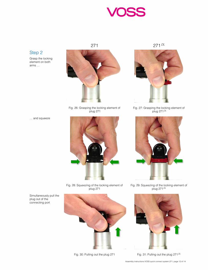
Step 2 Grasp the locking element on both arms …
Fig. 26: Grasping the locking element of plug 271
Fig. 27: Grasping the locking element of plug 271
DL
… and squeeze
Fig. 28: Squeezing of the locking element of plug 271
Fig. 29: Squeezing of the locking element of plug 271
DL
Simultaneously pull the plug out of the connecting port
Fig. 30: Pulling out the plug 271
Fig. 31: Pulling out the plug 271 DL
Assembly instructions VOSS quick connect system 271, page 13 of 14
271 271 DL
Step 3 Completely disassembled plug and connecting port Only 271
DL: Double Lock is again in front position (starting situation)
Fig. 32: Completely disassembled plug 271
with connecting port
Fig. 33: Completely disassembled plug 271 DL
with connecting port

Assembly instructions VOSS quick connect system 271, page 14 of 14
Customer service Contact VOSS for questions
concerning quick connectors,
nylon tubes, line routing, etc.
Property rights All rights reserved in regard
to patents, registered designs
and trademarks. Drawings of
the VOSS quick connect
systems 271 and 271 DL may
not be reproduced or made
accessible to third parties
without our prior consent.
Technical modifications and
errors excepted.
Contact VOSS Automotive GmbH
P. O. Box 15 40
51679 Wipperfürth
Leiersmühle 2-6
51688 Wipperfürth
Germany
Phone: +49 2267 63-0
Fax: +49 2267 63-5982
www.voss.net
7
0054396
00/2
01903
Sub
ject to
tech
nic
al m
od
ific
ations ©
VO
SS
Au
tom
otiv
e G
mb
H 2
019