Embed Size (px)
Citation preview

ASSEMBLY CODE TO MEMORY INITIALIZATION
FILE GENERATOR FOR THE SHIRA TOOL CHAIN
FOCUS ON THE LOADER SUB-PROJECT
Michael Montcalm B.A.Sc., M.A.Sc. (Candidate) School of Information Technology and Engineering (SITE)
University of Ottawa, Canada

2
TABLE OF CONTENTS Abstract ....................................................................................................................................................................................... 4
Introduction ............................................................................................................................................................................... 5
Overview of SHIRA ............................................................................................................................................................. 5
Overview of the Directed Study Project .................................................................................................................... 5
Reason for Development ................................................................................................................................................. 5
Literature Review .................................................................................................................................................................... 6
Third Party Loaders ........................................................................................................................................................... 6
Isa1 ....................................................................................................................................................................................... 6
Parse-Readelf ................................................................................................................................................................... 7
Existing Tool Chains .......................................................................................................................................................... 8
Dime-C ................................................................................................................................................................................ 8
HLL to HDL Generation [11] ...................................................................................................................................... 9
SHIRA Tool Chain .................................................................................................................................................................. 12
Overview .............................................................................................................................................................................. 12
Pre Compiler level ............................................................................................................................................................ 13
Compiler level .................................................................................................................................................................... 13
Post Compiler level .......................................................................................................................................................... 14
Hardware level................................................................................................................................................................... 14
Assembly to Memory ........................................................................................................................................................... 15
Assembler Requirements .............................................................................................................................................. 15
Linker Requirements ...................................................................................................................................................... 16
Loader Requirements ..................................................................................................................................................... 16
MifLoader Specifics ..................................................................................................................................................... 17
MemLoader Specifics.................................................................................................................................................. 17
Difficulties Encountered ........................................................................................................................................... 18
Example of using the loader .................................................................................................................................... 19
Running the Post Compiler Level ............................................................................................................................... 19
Industry Tools ......................................................................................................................................................................... 20
Xilinx’s Data2Mem Conversion Tool [6] .................................................................................................................. 20
Altera’s Elf2Mif Conversion Tool [10] ...................................................................................................................... 21
Reasons for Not Implementing the Tools ............................................................................................................... 21

3
Hardware/Compiler Interaction ..................................................................................................................................... 22
Experience Gained/Conclusions ..................................................................................................................................... 23
References ................................................................................................................................................................................ 25
Appendix A – MifLoader Code .......................................................................................................................................... 26
Appendix B – Asm2Mif code ............................................................................................................................................. 29

4
ABSTRACT This paper presents the steps taken to design and implement an assembly code to memory
initialization file converter. Specifically it details the conversion of the executable linked file format
to that of the memory initialization file format.
This project is a portion of a much larger ongoing research effort to design and implement a tool
chain to automatically parallelize and extend code and to generate a custom hardware platform for
this code to be run on. This paper will give an overview of the full tool chain before detailing the
steps involved in the implementation of the assembly to memory initialization file portion of the
project.

5
INTRODUCTION
OVERVIEW OF SHIRA There is currently a trend towards large software development in today’s programming fields. In
addition to this software trend, there is a trend towards smaller, multi-processor systems in the
hardware development fields. These two trends create a disparity between the software and
hardware fields. Software developers are able to create large systems with many features, but
cannot easily split the programs onto the many processors being developed by the hardware
developers.
The SHIRA project aims to tackle this issue in a user friendly way. Rather than having a
programmer manually parallelize their code or have intimate knowledge of the system it is being
designed for, SHIRA tries to minimize the effort on the part of the programmer. Our project’s goals
are to allow the programmer to code in a fashion that suites them (usually a very sequential
manner) as well as to let them specify their own architecture at a high level.
From there SHIRA will automatically parallelize the code based on the constraints provided by the
designer. To maintain efficiency, SHIRA will not go beyond the constraints that were provided. The
end result will be a program split over a multiprocessor system specified in whole or in part by the
user, which may contain co-processors, custom instructions, and other custom hardware.
OVERVIEW OF THE DIRECTED STUDY PROJECT There are many steps along the path from high level language to binary code stored in memory and
being run on a processor. The two projects assigned for this course were the development of the
customized assembler and linker for the allowance of custom instructions, and the development of
a translation tool or “Loader” which would take the output of the linker and convert it to one of
several memory initialization files to be used by the hardware.
The focus of this paper is on the development of the Loader portion of the tool chain. It provides
additional details about the Loader’s development and uses in comparison to the other sections of
the tool chain.
REASON FOR DEVELOPMENT The reasons behind the development of the Assembler-to-Loader portion of the tool chain are
twofold. First, the execution of the ISE portion of the compiler as developed by Daniel Shapiro
results in the addition of custom assembly code. These custom instructions need to be dealt with by
the assembler and linker before being translated to machine code.
Secondly, the hardware itself requires that each of its memories be initialized to be able to run the
code. These memories require specific file formats which must be developed from the end result of
the linker.

6
LITERATURE REVIEW
THIRD PARTY LOADERS The following summaries are of third party applications similar to the loader portion of the SHIRA
tool chain that this paper focuses on. They do not include the tools created by Altera and Xilinx.
These are mentioned separately in the “Industry Tools” section of the report, along with reasoning
for the creation of an in house tool.
Since the two tools below are both projects created by individuals and mimic the size and
functionality that is being pursued for the SHIRA tool chain’s Asm2Mif section, they are not formal
papers. As such, the descriptions of the programs’ bases and future goals are not covered as
thoroughly as would normally be in a formal paper. Both Isa1 and Parse-Readelf are presented
from a functionality standpoint and show more technical specifications and usage syntax than
would be seen in a paper.
ISA1 [7]
The Isa1 tool, created by J. Loomis is a simple set of scripts which can be used in conjunction with
the Nios II IDE to create *.mif files from assembly code. While the program does allow the use of
the Nios II IDE through the “.include” statement, is also allows direct use through the command line,
similar to the Asm2Mif program developed for the SHIRA tool chain.
The first step in running the script is to call GCC (similar to how Asm2Mif uses COINS to generate
the assembly). However, due to the fact that the call uses GCC, the gnu ld, and the gnu as, the
program is compiled, assembled and linked all in one step. There is no chance to observe the output
at any of the given stages. The shell script performs the function with the following call:
Now that the C code has been assembled by GCC, Isa1 uses the objdump command to output several
files containing the raw machine code for the assembly code created in the first step. In addition to
the objdump, Isa1 uses the size and nm commands to output information on the size and symbols
used in the program’s execution. The syntax of the second portion of the script is below:
To create the *.mif file, Isa1 first makes a copy of the a.out file created during the first step and
saves it off as a *.bin file. This is to ensure that the original a.out file is not tampered with, and to
allow for the creation of another text file containing results from the instruction set simulator. The
copying of the a.out file and the creation of the simulation results are done with the following two
commands:
nios2-elf-size a.out > ${name}.size.txt
nios2-elf-objdump -dS a.out > ${name}.disassemble.txt
nios2-elf-objdump -h a.out > ${name}.headers.txt
nios2-elf-nm a.out > ${name}.symbols.txt
name="isa1" nios2-elf-gcc ${name}.s

7
The final step is to use the *.bin file and run the mifwrite.exe portion of the tool. Mifwrite performs
nearly identical functions as the in house MifLoader, with some exceptions. Mifwrite creates a
single *.mif file, and manually spaces the different sections of machine code (.text, .data, .bss, etc…),
while the Mifloader separates these into distinct regions of the file, based on their starting
addresses. In addition, the Mifwrite program has the memory depth set at 256 instructions, while
Mifloader has been written to allow users to specify how deep the memory can be. The syntax for
calling the Mifwrite program can be seen below:
The “30” listed in the command is used to specify the offset of the main program to 0x30.
While the Isa1 program is quite similar to the home made Asm2Mif, it was not chosen to be
integrated into the tool for several reasons. First, the source code was not available to us, and as
this tool is small and supported only by the creator, the likelihood that specific needs would be
addressed in future releases of the program were small. Additionally, the lack of variable memory
depth was a concern, as larger programs would easily surpass 256 instructions. It was therefore
decided that while Isa1 was a good template to base our designs off of, it was not suitable for use in
the SHIRA tool chain.
PARSE-READELF [8]
Created by T. Dorner, the Parse-Readelf tool is designed with the intention of parsing the output of
the Readelf command in order to format the data for ease of access. It currently provides only
limited access to the structure of data types and variables. As of writing this review, only DWARF2
debugged code is supported by the tool. The Parse-Readelf tool was designed in Perl to be run
through the UNIX command line, and as such requires a Linux or Unix environment to run.
The benefit of this tool is that it is very easy to use to create the parsed files. Generating the parsed
data is done through a single command line command, shown below:
In this example, the $file_name is the name of the executable or object file to be parsed. The output
of this command is the parsed code, which can be accessed with several getter methods included
with the tool.
As with the Isa1 tool, Parse-Readelf requires GCC to be installed on the system and users must first
compile, assemble and link their files through this tool in order to produce the *.elf files to be
parsed by Parse-Readelf. As SHIRA uses the COINS compiler, which does not contain the gnu ld and
$readelf_data = new Parse::Readelf($file_name);
mifwrite ${name}.bin ${name}.mif 30
nios2-elf-objcopy -S -O binary a.out ${name}.bin
nios2-iss -td:${name}.sim.txt --trace-from=main -f a.out

8
gas, this would allow for the use of a custom assembler and linker to be used, so long as the output
file matched the *.elf that would have been produced by GCC.
As with the Isa1 tool, the major shortcomings of Parse-Readelf stem from the fact that it is a small
project created by an individual, and thus will have minimal support. In addition, the last changes
occurred in 2007, and the program is still in Aplha, at version 0.03. The likelihood that the project is
still ongoing and that the creator will be available for consultation is small, though the Parse-
Readelf has its source code available, should we wish to change it ourselves.
While those reasons are a portion of the reason why the Parse-Readelf tool was not used, some of
the more major issues stem from the fact that the output will still need to be translated into *.mif
format (which will still require coding on the part of the CARG team) and the fact that the Parse-
Readelf program was written in Perl, while the rest of the SHIRA tool chain was written in Java. It
was concluded that coding the MifLoader in house was a better option than using either Isa1 or
Parse-Readelf.
EXISTING TOOL CHAINS The literature reviews listed below are examples of other C to hardware compilers performing
similar functions to the COINS to Loader portions of the SHIRA tool chain. The summaries will be
mostly focused on the abilities of the authors’ tool chains and their similarities to the SHIRA tool
chain.
DIME-C [9]
In the early days of programming FPGAs, designers had to concern themselves with the physical
implementations of their algorithms due to the small amount of space available on each board. Due
to the ever increasing circuit density on FPGAs, the design strategies eventually moved upwards.
Designers began worrying less about the amount of physical space available on each piece of
hardware and how it would be mapped, and instead began to focus on the algorithms themselves,
as well as the circuit behaviours required to perform the algorithms.
The continuation of growth in circuit densities on FPGAs has created issues with determining how a
circuit will implement a given algorithm. The demand has risen for the creation of tool that will
abstract away the HDL code production in favour of allowing the designers to focus solely on their
algorithms. Several tools allowing designers to use high level languages (such as C, C++, FORTRAN)
now exist.
The advent of these tools has created a market niche for compilers which create HDLs from high
level languages. The scope of this paper deals solely with C-to-VHDL compilers, such as: DIME-C,
Carte, Impulse-C, Mitrion-C, Catapult-C, Handel-C and the Trident compiler. The subject of the
paper, Dime-C, is a subset of the ANSI C standard (as opposed to Impulse-C and Handel-C, which are
supersets of the ANSI C standard).
The biggest consideration that all FPGA HLL compilers must take into account is the physical
structure that will result from each algorithm. The fact that FPGAs have no theoretical pipeline

9
depth, and allow for many parallelism techniques, are reasons behind why they have such large
performance potential. The way in which the FPGA HLL deals with how parallel and pipelined code
is generated is a major distinguishing feature. Handel-C for example, forces the user to manually
specify which areas of their code will be parallel and which will be sequential. Dime-C’s approach is
similar to that of SHIRA’s, where the tool itself should determine how to parallelize and pipeline the
code, taking that burden off of the designer.
All users require testing to ensure that their code works, and FPGA HLL compilers must provide
this functionality as well. As debugging in hardware is extremely difficult, the vast majority of all
debugging should take place in software, running on a PC. With Dime-C code being a subset of the
ANSI C standard, the code can be compiled using a standard C compiler such as GCC.
Additionally, Dime-C provides the ability to integrate libraries into its language and instantiate
them as functions calls (as does Carte). There is also a push in the FPGA HLL community to create a
standard set of library cores that could be shared amongst the FPGA HLL tools, of which Dime-C’s
creator, Nallatech is a part of.
The paper goes on to discuss certain attributes and drawbacks of the Dime-C Syntax, such as its lack
of pointer support, lack of redundant switches and looping structures, and it’s lack of additional
keywords due to its self defined restriction to the ANSI C standard. The Dime-C IDE has additional
useful features, such as the ability to use different clock signals on both memory and logic blocks, as
well as resource sharing between non concurrent blocks of code, minimizing the amount of space
required.
The main section of the paper is a discussion of the recreation of two algorithms in Dime-C: the
DI3D and Monte Carlo algorithms. The intention was not only to show the improvements in run
time of the algorithm, but to show the ease with which a programmer can convert their code. The
development of the DI3D and Monte Carlo algorithms, including pipelining and parallelizing of the
code took nine weeks and just shy of two weeks respectively, and the speedup of the DI3D
algorithm was shown to be approximately 110 times over the software version.
In conclusion, the Dime-C compiler is an interesting attempt at solving the issues with parallelism
and pipelining in FPGAs. While it has several benefits, such as following the standard, and more
abstract definitions of parallel and pipelined code sections (in comparison to something like
Handel-C) is still lacks the automatic parallelization that the SHIRA project aims to provide.
HLL TO HDL GENERATION [11] While reconfigurable systems have the advantages of both flexibility and speed (as they are
executed in hardware) they suffer from drawbacks in the fact that developers of reconfigurable
systems must be fluent in knowledge of both software and hardware design. As not all
programmers and developers are so well versed, tools that allow for ease of movement from
hardware to software are a necessary development.
Workbenches aid designers by guiding them through the design process, stating with initial
partitioning of code in both software and hardware, through to implementation of the final design.

10
The Delft Workbench is based on this approach. Its goals are to provide the ability to design both
the hardware and software of a reconfigurable system in one program. The overall design flow of
the Delft Workbench is very similar to the SHIRA tool chain as a whole. An example of the design
flow for Delft is seen below in Figure 1.
Figure 1: Delft Workbench Design Flow
Delft works by first profiling C code written by a designer, and selects code fragments that would
work well as hardware blocks (similar to the Coprocessor design implemented in SHIRA). Delft
then uses a C to C compiler to restructure these code segments for the reconfigurable platform
(similar to the Pre-compiler MPI and OpenMP portions of SHIRA).
Delft then takes the code in two directions. A portion of the code not being turned into hardware is
compiled and has the necessary code sections that will become hardware turned into hardware
instructions (similar to the ISE identification use in SHIRA, as well as the post compiler portion of
the tool chain).
Those segments destined to become hardware blocks are passed through a VHDL generator which
either uses existing IP cores, or if necessary, prompts the user to create them manually from VHDL.
While this is also similar to the SHIRA tool chain, the CARG group is aiming to dynamically generate
new VHDL hardware blocks, instead of just using preexisting IP cores.

11
In addition to not merely using off the shelf hardware blocks, the SHIRA tool chain does not prompt
the user to manually create HDL code for critical components. This saves time in both development
of the code, and in the debugging of the code, as automatically generated code has far fewer user
related errors than manually developed code.
All of this processing of code in Delft will eventually be run on a MOLEN machine, which is made up
of a general core processor and a reconfigurable processor. These two processors communicate
through the use of exchange registers. A model of the MOLEN machine design is shown below in
Figure 2.
Figure 2: MOLEN Machine Design
Delft implements its VHDL generator in two major portions. The first, a dataflow graph builder,
accepts the annotated (for hardware implementation) C code as its input. Its goal is to use high level
optimizations on the C code and translate it to a form suitable for generation into hardware. It then
outputs the dataflow graph in a binary format for each function. Delft currently has only a partially
implemented the VHDL generator. It currently supports only if-statements, arrays in one
dimension, and logic operations for scalar values and arrays.
The second major portion of Delft’s VHDL generation the generator itself is a standalone application
that takes in the dataflow graph from the dataflow graph builder and a configuration file specifying
information such as memory word and address sizes. This generator then performs lower level
optimizations before generating the VHDL.
While posting decent speedup times (of 7X for an AES encryption), they fall well short of a manual
implementation of the AES algorithm, which clocks in at approximately 43X better than the
software performance. The Delft team concludes the paper stating that in order to create a higher
caliber of designs, the VHDL generator needs to be able to use high level semantics.

12
SHIRA TOOL CHAIN
OVERVIEW As discussed in the introduction section, the aim of the SHIRA tool chain is to develop a user
friendly approach to creating parallel custom multiprocessor systems. To allow a user’s code to be
parallelized first in software, and then broken up in hardware (through the use of instructions set
extension identification and coprocessor generation), and finally to be run on a custom
interconnection network of processors and memories the SHIRA tool chain is made up of several
stages, each of which prepare the user’s code for the next section.
COINS
Pre-Compilation Compilation
Post Compilation
Hardware Generation (SING)
MPI
OpenMP
Coprocessor
Generation
ISE Identification
AssemblerLinkerLoader
Memories Processors
Code.c
Figure 3: SHIRA tool chain flow

13
Figure 3 above represents an overview of the SHIRA tool chain. Running inside the COINS code are
two areas that have been split up based on when they modify code. The pre-compilation section
deals with the user’s code well before it is translated to assembly. The compiler section (including
the instruction set extension identification and coprocessor generation) deals with parts of the tool
chain that process the code around the time of compilation to assembly.
The post compiler section which is outside of the COINS code at the moment, processes the output
of the pre-compilation and compilation steps, and prepares the code to be placed into the final
section. The last section, SING, places the code into memories, and generates the hardware based on
user requirements and requirements of the instruction set extension and coprocessor generation
sections.
PRE COMPILER LEVEL The SHIRA tool chain itself needs some explanation in order to show where the assembler to loader
portion fits in. The description of the tool that follows is a brief, high level breakdown of the major
portions of the tool chain.
At the highest level are the automatic software parallelization tools. The two parallelization
technologies used are the Message Passing Interface (MPI) and the Open Multi-Processing
(OpenMP). The first, MPI occurs at the highest level, splitting the code from a single file into several
separate files based on decisions about how the code would work when split over multiple
processors communicating with message passing. These decisions work based on how much
communication is occurring between major sections of the program, and whether or not the code in
these sections can be run in parallel.
The second step in the software parallelization process is the OpenMP portion. Each of the files
coming out of the MPI section of the tool chain will (if necessary) pass through the OpenMP portion
of the tool. The OpenMP portion will analyze the code, looking for areas that would work well if
split over several processors all communicating with shared memory. It results in the creation of
parallelization “hints” which can be used by the compiler in the next portion of the tool chain.
COMPILER LEVEL The compiler being used in the tool chain is the Japanese Compiler INfraStructure (COINS) project.
COINS is essentially a version of the Gnu C Compiler (GCC) that has been rewritten in Java, with
many additions and improvements made to it. For the purposes of the tool chain, the pre compiler
components will be integrated into COINS, and will simply be called before the COINS driver
portion of the code (which creates the assembly code).
COINS itself will provide the standard tools for code improvements, such as dead code elimination.
However, just before the spill code is inserted, the code will be modified by the Instruction Set
Extension (ISE) identification developed by Daniel Shapiro. This portion of the project will search
the program for areas of code that could be represented by custom assembly instructions. It is
because of the ISE identification that modifications to the lower portions of the tool chain are
needed.
14
In addition to finding several small, repeating portions of the graph to generate custom
instructions, the compiler was used by the coprocessor generation tool developed by Vishal Theraja
to find large, complex portions of the graph with few inputs and outputs. These large graph
portions were then turned into custom hardware components. Currently, the system is designed
only to recognize the patterns generated by fuzzy logic controllers, through eventually the scope
will be expanded to include other complex processes.
POST COMPILER LEVEL After the code has been compiled by COINS (and has had all necessary modifications made to it by
the instruction set extension portion) and has been turned into unlinked assembly code, it can then
be passed to the post compiler section of the SHIRA tool chain. This section is comprised of three
tools: the Assembler, the Linker and the Loader. These tools were the main focus of the two papers
for this course. Their functions will be discussed in more detail in the Assembler to Memory
sections.
The assembler’s task is to process the assembly code created by the compiler. Using the Sparc v8
instruction set, with the added extensions, it converts the bare assembler into multiple sections of
assembly code, along with the raw machine code for each three register instruction. From here it
passes the code along to the Linker.
The Linker has the task of assigning where in memory the program will start, as well as connecting
(or linking) all of the disconnected portions of assembly and machine code that were created by the
compiler and assembler. From this it produces an executable linked file (*.elf). This replaces all of
the “call” instructions with the actual code that will be used by the program. From here, the file can
be moved to the last portion of the post compiler level.
The Loader has the task of parsing the *.elf file(s) and stripping them down to their bare machine
code for use in either the Altera *.mif memory file, or the Xilinx *.mem memory file. It does this by
stripping off the plain text and assembly code for each instruction, and creates the memory files
from the linked machine code. From here the memory files can be put into a hardware memory
block.
HARDWARE LEVEL The final portion of the SHIRA tool chain is the Simulation and Interconnection Network Generator
(SING). SING is designed to lay out the connections (point to point, shared bus, etc…) between the
processors arising from the use of the tool chain. It currently allows the user to specify processors,
and connections, and can generate the hardware automatically.
The goal of SING is to be able to communicate directly with the user (through an interface), the pre-
compiler level, the coprocessor generator, and the instruction set extension identification section in
order to create both user specified and automatically generated processors and coprocessors over
an interconnection network.

15
ASSEMBLY TO MEMORY The first steps after the COINS compiler has output the assembly code are assembly and linking of
the assembly code. In this case, an assembler and linker must be added to the SHIRA tool chain, as
the COINS compiler does not come pre-packaged with an assembler and linker. To allow for the
input of custom instructions created in the compilation phase, each of these tools must be
customized to allow for new assembly instructions.
The installation and modifications of this portion of the tool chain were performed by Jonathan
Parri, and are discussed in more detail in the sister report to this one. A brief overview of the
requirements and the syntax for use of the assembler and linker are provided below.
ASSEMBLER REQUIREMENTS The assembler’s function is to take in the assembly code created by COINS, and generate both a text
file of machine code, as well as a *.elf file. The assembler must also be able to create machine code
for custom instructions.
The assembler code is made of modified versions of both the GNU as.exe and readelf.exe. Due to
issues with compatibility of different versions of the assembler, multiple versions of the software
were tested before binutils-2.16 was chosen as the correct version.
The assembler code itself is run through the GenerateMain.java file, which runs the assembler,
linker and loader. GenerateMain calls the assembler with the filename of the assembly *.s file
created by COINS. Due to the fact that multiple assembly files may be created by COINS (because of
some of the pre-compilation steps), GenerateMain calls the assembler inside a loop. An example of
the code used to call the assembler is listed below:
Assembler assemble = new Assembler();
//Get assembly files
int numberOfFiles=1;
System.out.print("Number of .s files to assemble:
");
numberOfFiles = (int)getInput(br);
// Allocate array memory for addresses
fileNames = new String[numberOfFiles];
for(int i=0; i<numberOfFiles; i++)
{
System.out.print("File " + (i+1)+": ");
try {
fileNames[i] = br.readLine();
} catch (IOException e) {
e.printStackTrace();
}
assemble.run(fileNames[i]);
}

16
LINKER REQUIREMENTS The Linker’s responsibility is to take the machine code output from the Assembler and link it into a
form that can be executed. The Linker must also be modified to allow for the use of custom
instructions, and must output the code in the form useable by the Loader. Due to the fact that the
Linker code is broken up into several different classes, the call from GenerateMain is quite simple.
The Linker is called with the names of the files created from the Assembler, the start and end
addresses of the machine code, and the buffered reader variable. An example of the Linker being
called can be seen below:
The final output of the Linker is a test file of the machine code, organized in 16 byte increments
(four sets of four byte long instructions). It is this file that is parsed by the Loader to create either
the *.mif or *.mem file. An example of a simple program that has been linked and has been output in
readelf format is listed below:
LOADER REQUIREMENTS The Loader section of the tool chain had to meet several requirements for the generation of
memory files from the output of the linker. Before getting to the Loader, it was agreed that the
output of the linker should be in readelf format. This simple command in the linker saved
potentially hundreds of lines of code that would have been needed in the Loader to translate the
executable linker file (*.elf) to an easily parsed format. An example of readelf format can be seen in
the code above.
The first step in parsing the output was to strip away all of the pieces of readelf code that was not
machine code. As can be seen in the example above, these included the addresses, as well as the
plain text on the right hand side. The plain text could simply be discarded once it was parsed, and
was simple to remove.
Due to the fact that the Loader needed to be designed to insert empty code when there were gaps in
the readelf output, the 0x addresses needed to be retained for later use. This function was also
performed by the parsing method in the Loader code. After being stripped out of the file, the
Hex dump of section '.text':
0x00000010 9de3bfa0 31000000 b0162048 f2060000 ....1..... H....
0x00000020 31000000 b016204c f0060000 b0064018 1..... L......@.
0x00000030 33000000 b2166050 f0264000 81c7e008 3.....`P.&@.....
0x00000040 81e80000 ....
Hex dump of section '.data':
0x00000044 00000000 00000001 00000002 ............
Section '.bss' has no data to dump.
Linker linker = new Linker();
linker.run(fileNames,startAddress,endAddress,br);

17
addresses and code needed to be placed in order. The method used was to parse the remaining
code line by line.
Each address was stripped of its “0x” prefix, and was used in a line counter. The address was
incremented by 416 each time an instruction was inserted into the memory file as the instructions
are four bytes long for the Sparc code being worked with. To ensure that gaps in the code were
dealt with, each address was compared to its predecessor. If there was a discrepancy between the
two addresses, strings of zeros were inserted to make up the difference.
Due to the fact that not all lines in the readelf code were exactly four instructions wide (as can occur
with the end of a set of instructions), a set of error checks was required to ensure that only the
instructions were allowed to be parsed. For this, a set of checks requiring that the parsed values be
exactly eight characters long (no “space” characters were allowed) with only hex values was used.
MIFLOADER SPECIFICS
Specific to the MifLoader program were several values used to determine the type of memory being
used. Altera’s *.mif file contains information about the memory width and length, as well as in
which radix the memory is being stored. For the purposes of setting up the single processor tool
chain, the only memory types being used are 32 bits wide, written in hexadecimal for both the
instructions and the line counter.
As the tool chain moves towards more flexibility, the values for these memories, as well as the code
that creates the files, may be modified to allow for multiple widths (depending on the type of
memory being used) as well as multiple radices. Currently only the memory size is available as a
variable input, as the default of 256 (or FF16) is far shorter than the majority of programs that will
be used in testing the tool chain.
Also specific to the MifLoader was the use of the line counter based on the passed addresses from
the readelf file. Altera’s *.mif contains a counter in the file, showing the current address of each
instruction. It also allows for ranges to be given with the same instruction. This is highly useful
when the program size is much smaller than the memory length. Otherwise, the file would be filled
with a large range of empty instructions at the end, which would increase the file size, as well as the
time to create the file. To allow for the use of this feature, the line counter is incremented a final
time before being listed in the file along with the variable for the memory length. An example of
what this final range in a memory file would look like is listed below in Figure 2.
Figure 4: Example of empty range in *.mif
For the purposes of the example, the program length is 2A16 instructions long, while the memory
length is the standard 256 (0 to FF16) instructions long.
MEMLOADER SPECIFICS
Due to the simplicity of the Xilinx memory initialization file (*.mem), the MemLoader reuses much
of the code made for the MifLoader, which was coded first. While the MemLoader does not

18
currently implement all of the features coded for it, the code was left intact to allows for ease of use
should Xilinx ever change its method of creating *.mem files.
The *.mem files from Xilinx are simple binary files, with each instruction separated by carriage
returns. An example of a *.mem file can be seen in Figure 3.
Figure 5: format of a Xilinx *.mem file
Unfortunately, due to the simplistic characteristics of the file, it results in an output format that is
not human readable.
DIFFICULTIES ENCOUNTERED
While the MifLoader and MemLoader projects were relatively easy to code, they were not without
issue. The first hurdle to overcome was simply deciding what format to use to begin the parsing of
the machine code. After examining the different fashions that the assembly and machine code could
be output from the linker, it was decided that the readelf format listed in the end of the Linker
Requirements section was the simplest to parse.
The first coding hurdle came with the initial calling of the input file in the main class of the Loader.
An oversight with the args0[] array lead to some difficulties in calling the correct file name, as the
filename was being given a null value. The solution was simply to fix which element in the array the
program was calling.
While not a coding issue per se, there was some issue with checking for erroneous entries in the
code. Due to the format chosen for the readelf input, the Loader had to ensure that the plaintext
code to the right of each line of machine code was not erroneously included in the output of the
*.mif file. To ensure that the code was being parsed correctly, the filters applied to weed out any
erroneous lines of code were done in stages.
The only other issue with the code was specific to the Xilinx MemLoader portion of the code. The
*.mem output uses a 32 bit long binary string for each machine code instruction, so the Loader was
required to translate the incoming hexadecimal machine code to binary. This required that the hex
string be turned into an integer before being output again as another binary string. However, after
coding this portion, the majority of the machine code instructions would cause the program to
generate errors.
After poring over the code, and using external examples to verify, it was discovered that the larger
machine code instructions (for example, those beginning with “FF” as their first instruction) were
too large to be contained by a single integer, as an eight bit hex number has a range up to about 4.3
billion, whereas a signed integer has a range only as high as half that. Rather than use unsigned
integers, we opted instead to move to a double value.

19
EXAMPLE OF USING THE LOADER
The Loader is called with a very simple set of arguments used to create the final memory file. There
are currently three arguments used in the calling of the MifLoader, all of which are used. The same
inputs are fed into the MemLoader, though only two of them are currently implemented. The
reasoning behind this was briefly outlined in the MemLoader Specifics section, but will be explained
in more detail here.
The MifLoader program requires the user to specify the input file, the name of the file to be created,
as well as the depth or size of the memory block. The default value for the *.mif was 256
instructions, but was made flexible for longer programs. An example of the syntax of calling the
MifLoader can be seen below:
MifLoader load = new MifLoader();
load.readMachineCode("inputFile.code","outputFile.mif",256);
As the MemLoader program is a near copy of MifLoader, it also has the memory size specification in
its initial arguments, though this value is currently not used. It was left in the program in the event
that a counter for the memory size is implemented by Xilinx. By leaving this code in place, it makes
any modification for adding a counter much simpler. The syntax of MemLoader is shown below:
MemLoader load = new MemLoader();
load.readMachineCode("inputFile.code","outputFile.mem",256);
The MifLoader currently has three other values that could be made dynamic. These are the memory
width, the address radix and the data radix. The memory width specifies the number of bits that
make up each instruction. It is currently set at 32, as the project is only dealing with 32 bit
processors. If the project is ever extended to include 64 bit processors, this value will need to be
added to the list of arguments used when calling the program.
The address and data radices are used to specify what base the instructions and counter are listed
in. The default for Altera *.mif files is hexadecimal. The only reason for changing this value to
anything different would be a matter of personal preference (for example, if the user wished to see
the counter count in decimal for ease of reading). While there are no current plans to make these
values dynamic, the change would be easily accomplished if a request was made.
RUNNING THE POST COMPILER LEVEL Due to the fact that the post compiler portion of the tool chain consisted of several separate pieces
of code, it was decided that a program should be coded to run all sections sequentially, as opposed
to forcing the user to perform the same task manually. Two separate programs were coded, one
designed to generate *.mif files, and the other to generate *.mem files (Asm2Mif and Asm2Mem
respectively).
These programs run all components separately, first by running the assembly code from COINS
through the customized assembler to produce the unlinked machine code. The code is then passed
through the linker, producing several *.elf files (corresponding to the .data, .text, etc… sections of
the program). Finally each of these files is run through the Loader program. The final output of the

20
Asm2Mif/Asm2Mem program is one *.out file, three readelf files (output as *.code files) and three
*.mif or *.mem files, corresponding to the readelf files.
The run time of the post compiler section of the tool chain is very short. After the addition of a
performance counter, the test program of a simple “a=b+c” (in the test file simplest.s) was found to
run on the Asm2Mif in approximately 797 milliseconds. As a significant amount of the runtime is
compromised by the creation of the introduction section in the *.mif file, the simplest.s program
was retested with the Asm2Mem program. This was found to have a much shorter runtime at only
313 milliseconds.
INDUSTRY TOOLS In the process of creating the assembly to memory initialization file portion of the tool chain, our
research lead us to finding two pre-existing programs that could accomplish the same task. The
programs were provided from Altera and Xilinx and were designed to allow a user to simply input a
*.elf file and create from it a memory initialization file (either *.mif or *.mem depending on the
company). In the subsections below, we’ll look at the functions that are provided by these tools, as
well as an explanation of our decision to not use them.
XILINX’S DATA2MEM CONVERSION TOOL [6] The more robust of the two tools, the Xilinx Data2Mem tool allows for several input file types to be
translated to one or more of several output file types. The simplest of the files input to Data2Mem is
the Block RAM Memory Map (*.bmm) file. The *.bmm file is a simple text file describing individual
RAM blocks and how they constitute a data space. The other two input files are the Executable and
Linkable Format (*.elf) Files and Debugging Information Format DWARF (*.drf) Files. These are
both binary data files that contain an image of executable code, ready to be run on the processor.
The *.drf file differs from the *.elf in that it also contains debugging information.
Figure 6: Data2Mem Tool Inputs and Outputs
Data2Mem has two file types that can be used as both input and output files. These are the Bit
Stream (*.bit) Files and the Memory (*.mem) Files. For the usage in the tool chain, the *.mem file is
a simple 32 character wide binary file describing a block of memory. The *.bit file is a simple binary
file containing a bit image for use on an FPGA device. Of the other types of output files creatable by

21
Data2Mem, both major types are output as standard text files. These are the Verilog (*.v) and VHDL
(*.vhd) files, both of which contain data used to initialize block RAMs.
ALTERA’S ELF2MIF CONVERSION TOOL [10] Like Xilinx, Altera also provides a tool (or in this case, a set of tools) used for converting file formats.
Altera has a set of eight tools (seen in Table 1) which can be used to convert different file types to
formats useful when programming Altera devices.
Utility Description
bin2flash Converts binary files to a Motorola S-record file (.flash) for programming into flash memory.
elf2dat Converts an executable and linking format file (.elf) to a .dat file format appropriate for Verilog HDL hardware simulators.
elf2flash Converts an executable and linking format file to an S-record file for programming into flash memory.
elf2hex Converts an executable and linking format file to the Intel hexadecimal file (.hex) format.
elf2mem Generates the memory contents for the memory devices in a specific Nios II system.
elf2mif Converts an executable and linking format file to the Quartus II memory initialization file (.mif) format
flash2dat Converts an S-record file to the .dat file format appropriate for Verilog HDL hardware simulators.
sof2flash Converts an SRAM object file to an S-record file for programming into flash memory.
Table 1: Altera File Conversion Utilities [10]
These utilities are all called through the SOPC Builder command line, and could be called through a
Java program if needed. The syntax of elf2mif requires the input of the elf file, the beginning and
end values of a range to transform in the elf file, the width value needed to be specified in the mif
file, a Boolean value specifying whether or not to create lanes, and finally the output file name. An
example of the syntax in use is seen below:
[SOPC Builder]$ elf2mif foo.elf 0 0x0FFF –width=32 –create_lanes=1 bar.mif
As each of the tools was developed separately, the syntax for each is quite varied, as is the help
information for each tool.
REASONS FOR NOT IMPLEMENTING THE TOOLS As with the other tools researched, there were reasons behind why these industry tools were not
chosen. Altera’s file conversion command line tools were found almost immediately in the search
for a tool to create the *.mif files from the *.elf files. However, after several attempts to run the
utility, no progress had been made in understanding how to use the program. Each attempt was
either met with a vaguely defined error, or with the default statement that the syntax was incorrect
(despite repeated checks to ensure its validity).
Unfortunately, the Elf2Mif conversion utility had no substantial documentation regarding the
formats of the elf file (as *.elf files can be output in several fashions). Nor did the documentation

22
contain substantial troubleshooting or tips for using the utility. Additionally, the fact that the
program came in a binary format, and was not available for editing meant that any issues would be
nearly impossible to fix without first going through Altera.
It was agreed upon that the benefits of using a pre-made program were outweighed by the fact that
we would retain full control over an in-house conversion utility. The decision to go forward with
the creation of the MifLoader was then undertaken.
As the development of the first version of the MifLoader came to an end, research into the creation
of the Xilinx memory formats began. It was only at this stage that the Xilinx Data2Mem tool was
discovered. As this pre-built conversion tool would also have the same drawbacks as the Elf2Mif
utility that Altera had provided, it was again decided that an in-house utility was the best choice.
As it was possible to reuse much of the MifLoader code in the creation of the MemLoader program,
greatly shortening the development time, the costs of developing this second program were
substantially lower than in the development of the MifLoader.
HARDWARE/COMPILER INTERACTION The interaction between the MifLoader and the hardware portion of the tool chain is limited to the
use of memories. As the portion of the tool chain worked on for the papers presented for the
directed study merely cover the post compilation portion of SHIRA, the references from COINS to
SING were not done here. COINS will reference SING at a higher level, and will generate the VHDL
that will make the hardware to be used later.
This generated VHDL will be placed into different folders of a pre-existing folder structure that can
be used in Quartus II. The MifLoader portion of the post compilation section will also be required to
save the *.mif file(s) created into the same folder structure. This feature is currently not
implemented, as the folder structure and SING are not fully complete.
However, the modification of the MifLoader (and the Asm2Mif code) will simply be a request for the
folder location. From there the MifLoader can create the new *.mif file in the required folder. The
created *.mif files have already been tested for validity and as can be seen in Figure 7 below, can be
opened in Quartus II.

23
Figure 7: *.mif file loaded in Quartus II
As each instruction is four bytes in length, the addresses of each instruction are every fourth byte.
Should the MifLoader be changed to output *.mif files in binary (which can be easily implemented),
the addresses for each instruction would be every byte.
EXPERIENCE GAINED/CONCLUSIONS While the main goal of the project was to further the development of the post compiler region of the
SHIRA tool chain, there was also the goal of educating the persons responsible for the programming
and design of the Asm2Mif and Asm2Mem tools. In the delivery of the tool as well as the report,
several opportunities for learning were taken advantage of.
The primary area of learning was in the creation of the programs themselves. Throughout the
project’s lifespan, the programmers were able to refresh skills in Java coding that have not been
heavily utilized since the second year of the CEG undergrad program (as many of the projects
consist of VHDL or C coding).
Additionally, the coding allowed for chances to refresh and learn more about the proper
development of requirements gathering. While a quick script to parse code could be created in a
few hours, gathering all of the requirements for both the input and output of the files allowed for
the creation of a more flexible and dynamic tool.
In addition to using proper requirements gathering, the use of Java (combined with several object
oriented courses taken this semester) allowed for the programmers to design a more modular
program. The code for the Asm2Mif tool has been developed in a way that makes is much simpler to
modify the output of the program and add more features if necessary.

24
The project did not merely offer opportunities to improve coding and requirements gathering skills.
The report portion of the project itself also had many learning opportunities. While little emphasis
is placed on proper writing techniques in the undergrad portion of school, the creation of this
report helped to further hone literature review and summarization skills. It also improved the
ability to properly cite work, and properly structure a report.
In summary, the project was successful not only from a technical perspective in that it achieved the
goals of proposing, designing and implementing the post compiler portion of the tool chain, but also
from a non technical perspective. Several learning opportunities (both technical and non technical)
were taken advantage of, and in the process, furthered the knowledge of the programmers.

25
REFERENCES [1] J. D. Newcomb, A Scalable Approach to Multi-core Prototyping, M.s. Thesis, Bradley Department
of Electrical and Computer Engineering, Virginia Polytechnic Institute and State University, Blacksburg, Virginia, 2008. [Online]. Available: http://scholar.lib.vt.edu/theses/available/etd-01312008-113612/unrestricted/ JD_Newcomb_Masters_Thesis.pdf [Accessed: May 26th, 2008]
[2] Ta Quoc Viet, Tsutomu Yoshinaga, Ben A. Abderazek and Masahiro Sowa, Construction of Hybrid
MPI-OpenMP Solutions for SMP Clusters IPSJ Digital Courier, Vol. 1, pp.153-165. 2005. [Online]. Available: http://www.jstage.jst.go.jp/article/ipsjdc/1/0/1_153/_article [Accessed: May 28th, 2008]
[3] P. G. Paulin, et al. Parallel Programming Models for a Multiprocessor SoC Platform Applied to
Networking and Multimedia, IEEE Transactions on Very Large Scale Integration (VLSI) Systems, Vol. 14, No. 7, 2006. [Online]. Avialable: http://ieeexplore.ieee.org/iel5/92/34767/01661617.pdf [Accessed: May 20th, 2008]
[4] R. Brightwell, A Comparison of Three MPI Implementations for Red Storm, Scalable Computing Systems, Sandia National Laboratories Albuquerque, NM (USA) 2005. [Online]. Available: http://www.springerlink.com/content/dnmk3a7em716qvw4/ [Accesses: May 27th, 2008]
[5] B. Vinter, A comparison of Three MPI Implementations, University of Southern Denmark, Odense M, Denmark. J. M. Bjørndalen, O. J. Anshus and T. Larsen, University of Tromsø, Tromsø, Norway, 2004. [Online]. Available: http://www.cs.uit.no/~johnm/publications/pdf/vinter2004comparison.pdf [Acessed: May 29th, 2008]
[6] Data2Mem User Guide, Xilinx Inc., version 2.0, December 2007, Available at: http://www.xilinx.com/itp/xilinx10/books/docs/d2m/d2m.pdf
[7] J. Loomis, isa1, Last updated February, 2008, Available at: http://www.johnloomis.org/srisc/nios2-isa/isa1/isa1.html
[8] T. Dorner, Parse::Readelf – Handle Readelf’s Output with a Class, Version 0.03, Last updated December 2007, Available at: http://search.cpan.org/~dorner/Parse-Readelf-0.03/lib/Parse/Readelf.pm
[9] G. Genest, R. Chamberlain, R. Bruce, Programming an FPGA-based Super Computer Using a C-to-
VHDL Compiler: DIME-C, Nallatech Ltd., Second NASA/ESA Conference on Adaptive Hardware and Systems, 2007, Available at: http://ieeexplore.ieee.org/stamp/stamp.jsp?arnumber=04291932
[10] Altera, Nios II Software Developer’s Handbook,Chapter 13, Altera Corporation, May 2008, Available at: http://www.altera.com/literature/hb/nios2/n2sw_nii52011.pdf
[11] Y. Yankova, K. Bertels, S. Vassiliadis, G. Kuzmanov, R. Chavez, HLL-to-HDL Generation:
Results and Challenges,Computer Engineering Laboratory, Delft University of Technologies, 2006, Available at: http://ce.et.tudelft.nl/publicationfiles/1247_623_prorisc2006_yankova.pdf

26
APPENDIX A – MIFLOADER CODE package gen;
import java.io.*;
/**
*
* @author Michael Montcalm
* Created: September 2008
* Editors: Jonathan Parri, Daniel Shapiro
*
* The MifLoader class is responsible for conversion of the *.elf linked file
* to the *.mif format. Details on the function of the methods are listed at
* the beginning of each.
*
*/
public class MifLoader {
/**
* readMachineCode is responsible for iteratively reading through the input
* file, and sending each line to parseMachineCode to be broken into the eight
* character long hex commands which will be printed to the mif file.
* @param args contains the name of the specified input file
*/
public void readMachineCode(String mDump, String outputFileName, int memorySize) {
String input_code = null;
//args.toString(); //convert the file specified by the user to string
int counter = 0;
try {
FileReader fr = new FileReader(mDump); //reads specified input file
BufferedReader br = new BufferedReader(fr);
BufferedWriter out = new BufferedWriter(new FileWriter(outputFileName));
//MIF file to be created and written to.
MifLoader intro = new MifLoader();
intro.writeIntro(out, memorySize);
input_code = new String();
int line_counter = 0;
while ((input_code = br.readLine()) != null)
{
counter++;
int letter_counter = 0;
String output_code = new String();
output_code = ""; //Keeps duplicate strings from being printed.
input_code.toLowerCase(); //Done to make a check in the next method less complex.
MifLoader parse = new MifLoader();
line_counter=parse.parseMachineCode(input_code,output_code,letter_counter,line_counter,out);
}
//----------------------------------------------------------------
//The following code reads the final value of line_counter,
//converts it to hex, pads it with zeros, and prints it and the
//last line of code before closing the file
String temp = Integer.toHexString(line_counter).toUpperCase();
if(temp.length()==1)
{
temp="00"+temp;
}
else if(temp.length()==2)
{
temp="0"+temp;
};
out.write(" ["+temp+".."+Integer.toHexString(memorySize-1)+"] : 00000000;");
out.newLine();
out.write("END;");
out.close();
System.out.println(".mif file created!");
//---------------------------------------------------------------
}
catch (IOException e)
{
System.out.println("Loader Error 1: Wrong input file name or file does not exist.");

27
e.printStackTrace();
}
}
/**
* parseMachineCode reads in each line of the input file, removing all but the
* eight digit long hex code which will be output (once formatted) into the mif
* file in the loops below.
*
* @param input_code is the original line that was read in the previous method
* @param output_code is the string containing data separated by spaces. During the
* course of the method, all invalid instances will be dropped.
* @param letter_counter counts which character is being read for the purpose of
* not reading beyong the length of a string
* @param line_counter counts which line is being printed
* @param out being passed to the writeToFile method
* @return returns the line_counter to the readMachineCode method for use in
* printing the final line.
*/
int parseMachineCode(String input_code, String output_code, int letter_counter, int
line_counter, BufferedWriter out)
{
int intvalue = 0;
while(letter_counter < input_code.length())
{
char letter;
letter = input_code.charAt(letter_counter);
String hexline = "";
if(letter != ' '){ // Build up groups of characters separated by spaces
if(letter == '0'||letter == '1'||letter == '2'||letter == '3'||letter == '4'||letter == '5'||
letter == '6'||letter == '7'||letter == '8'||letter == '9'||letter == 'a'||
letter == 'b'||letter == 'c'||letter == 'd'||letter == 'e'||letter == 'f'||letter == 'x')
{
output_code = output_code + String.valueOf(input_code.charAt(letter_counter));
}
}
else if(output_code != "")
{ // Check to see if strings have "0x" in them, denoting the address
if(output_code.contains("0x"))
{
hexline=output_code.substring(2, output_code.length());
intvalue = Integer.parseInt(hexline, 16);
line_counter=intvalue;
output_code = "";
}
else if (output_code.contains("x"))
{ //Strip out any words that may contain 'x' as we no longer need to look for it
output_code = "";
}
else if(output_code.length() == 8)
{ // Find only 8 digit long code containing the letters above (hex digits only)
try
{
out.write(" " + Integer.toHexString(intvalue) + " : " +output_code + ";");
out.newLine();
}
catch (IOException e)
{
e.printStackTrace();
}
intvalue=intvalue + 4;
line_counter= line_counter + 4;
output_code="";
}
}
else
{
output_code = "";
}
letter_counter++;
}

28
return line_counter;
}
/**
* writeIntro is a static method that simply prints the copyright information and information
* such as the depth and width. Should the toolchain be redesigned to accept variations in
width,
* depth, and data and address radix formats, the code changes will need to occur here.
* @param out used in writing to the file
*/
void writeIntro(BufferedWriter out, int memorySize){
try
{
out.write("-- Copyright (C) 1991-2007 Altera Corporation");
out.newLine();
out.write("-- Your use of Altera Corporation's design tools, logic functions ");
out.newLine();
out.write("-- and other software and tools, and its AMPP partner logic ");
out.newLine();
out.write("-- functions, and any output files from any of the foregoing ");
out.newLine();
out.write("-- (including device programming or simulation files), and any ");
out.newLine();
out.write("-- associated documentation or information are expressly subject ");
out.newLine();
out.write("-- to the terms and conditions of the Altera Program License ");
out.newLine();
out.write("-- Subscription Agreement, Altera MegaCore Function License ");
out.newLine();
out.write("-- Agreement, or other applicable license agreement, including, ");
out.newLine();
out.write("-- without limitation, that your use is for the sole purpose of ");
out.newLine();
out.write("-- programming logic devices manufactured by Altera and sold by ");
out.newLine();
out.write("-- Altera or its authorized distributors. Please refer to the ");
out.newLine();
out.write("-- applicable agreement for further details.");
out.newLine();
out.newLine();
out.write("-- Quartus II generated Memory Initialization File (.mif)");
out.newLine();
out.newLine();
out.write("WIDTH=32;"); //Currently static, will need to be changed if accepting variable
width
out.newLine();
out.write("DEPTH="+memorySize+";"); //Currently static, will need to be changed if accepting
variable depth
out.newLine();
out.newLine();
out.write("ADDRESS_RADIX=HEX;"); //Currently static, will need to be changed if accepting
variable address radix values
out.newLine();
out.write("DATA_RADIX=HEX;"); //Currently static, will need to be changed if accepting
variable data radix values
out.newLine();
out.newLine();
out.write("CONTENT BEGIN");
out.newLine();
}
catch(IOException e)
{
System.out.println("Loader Error 3: Introduction not printed properly");
e.printStackTrace();
}
}
}
29
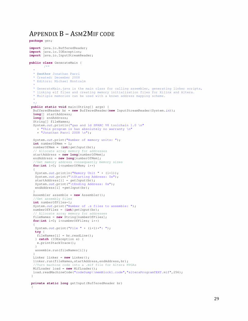
APPENDIX B – ASM2MIF CODE package gen;
import java.io.BufferedReader;
import java.io.IOException;
import java.io.InputStreamReader;
public class GenerateMain {
/**
*
* @author Jonathan Parri
* Created: December 2008
* Editors: Michael Montcalm
*
* GenerateMain.java is the main class for calling assembler, generating linker scripts,
* linking elf files and creating memory initialization files for Xilinx and Altera.
* Multiple memories can be used with a known address mapping scheme.
*
*/
public static void main(String[] args) {
BufferedReader br = new BufferedReader(new InputStreamReader(System.in));
long[] startAddress;
long[] endAddress;
String[] fileNames;
System.out.println("gas and ld SPARC V8 toolchain 1.0 \n"
+ "This program is has absolutely no warranty \n"
+ "Jonathan Parri 2008 \n");
System.out.print("Number of memory units: ");
int numberOfMem = 1;
numberOfMem = (int)getInput(br);
// Allocate array memory for addresses
startAddress = new long[numberOfMem];
endAddress = new long[numberOfMem];
//Get memory address consequently memory sizes
for(int i=0; i<numberOfMem; i++)
{
System.out.println("Memory Unit " + (i+1));
System.out.print("\tStarting Address: 0x");
startAddress[i] = getInput(br);
System.out.print("\tEnding Address: 0x");
endAddress[i] =getInput(br);
}
Assembler assemble = new Assembler();
//Get assembly files
int numberOfFiles=1;
System.out.print("Number of .s files to assemble: ");
numberOfFiles = (int)getInput(br);
// Allocate array memory for addresses
fileNames = new String[numberOfFiles];
for(int i=0; i<numberOfFiles; i++)
{
System.out.print("File " + (i+1)+": ");
try {
fileNames[i] = br.readLine();
} catch (IOException e) {
e.printStackTrace();
}
assemble.run(fileNames[i]);
}
Linker linker = new Linker();
linker.run(fileNames,startAddress,endAddress,br);
//Turn machine code into a .mif file for Altera FPGAs
MifLoader load = new MifLoader();
load.readMachineCode("codeDump\\memBlock1.code","alteraProgramTEXT.mif",256);
}
private static long getInput(BufferedReader br)
{

30
long temp=0;
try {
temp = Long.parseLong(br.readLine(),16);
} catch (IOException e) {
e.printStackTrace();
}
return temp;
}
}