Embed Size (px)
Citation preview
ASSEMBLY & INTEGRATIONFunktional Pivot NL
Patented technology
For door leafs up to 1250 mm and 75 kg
1
2 year manufacturers Guarantee - Warranty
Functionality:180° swing operation with a silent 90° hold function90° / 0° / -90°
Maximum weight & dimensions:75 kg - 165 lbsMax. door width 1250 mm( approx. 49.21 inches | 25.4 mm = 1 inch )
Closure force:Adaptable with 2 sets of Suspa gas springs, rated at 300N and 400N. The hinge is equipped with 300N out of the box.The additional gas springs are sold separately, but extensive testing has proven that 300N is the most adequate all-round setup.The closing force is influenced by environmental aspects such as room and joint dimensions, air tightness, overall weight of the door,... and has to be adjusted accordingly by trial and error. The gas springs are exchangeable to adjust the closing force of the hinge as necessary.
Suitable for:Interior doors made from any type of material, with a minimal thickness of 30 mm, for hinge integration purposes.
Swing operation:180° swing operation with a silent 90° hold function in all swing directions 90° / 0° / -90°We include a magnetic 2-way door positioning accessory that can be fitted on top of the door with a small counterpart against the ceiling for positioning purposes. We also include an optional 1-way accessory. This 1-way configuration both positions the door at 0° and blocks the door when 1-way 90° swing operation is necessary or desired.
Minimum pivot point distance:The axis point can be positioned at either 80 mm or 178 mm by simply turning the hinge around in the cavity inside the door panel.
Closed door positioning (0°)The self-closing technology will position the door at 0° when installed perfectly. The hinge mounts feature a correction & adjustability system with octagonal bolts to fine-tune the door leaf position at 0° after initial installation. We also include a set of magnets to ensure that the positioning at 0° is guaranteed after installation. Installation of the magnet(s) accessories are optional.
Joint dimensions:The advised joint dimensions are based on a completely square (rectangular)opening. Please read our detailed instructions regarding dimensions & joint calculation in the instruction manual.Bottom: 11 mmTop: 12.5 mm (necessary for optional magnets & 1-way)Left and right: 4 - 5 mm advised (up to 50 mm thick panel)Larger panels need to be recalculated accordingly
Funktional Pivot NL – Technical specifications
2

Funktional Pivot NL complete kit content
‘Complete’ kit content is displayed 3
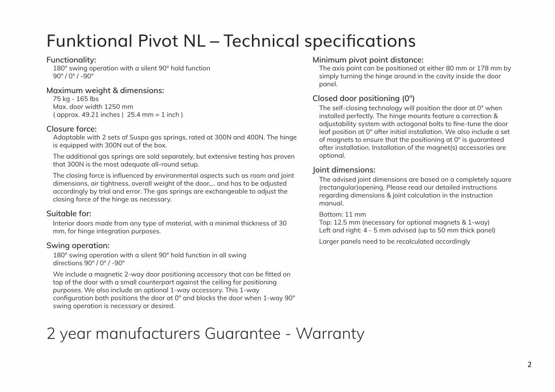
Funktional pivot NL ‘Complete’ kit parts132 mm 25,25 mm
20 mm
21 m
m16
mm
41,5
mm
96 mm
30 mm45 mm
97 mm
92 mm
25 mm
30 mm45 mm
30 mm
10 mm
45 mm
14 mm
ISO10642-M4x8
AWD-S90
PAP-1WAYWW-black/white
SP-PS&KAL
PAP-1WAY-black/white
Magneet 25x5 - north/south
DIN916-M6x8
carrosseriering M5x25
DIN 988-5x10x1 (shims)
PAP-1WBUP
Maxxfast VK 4,5x50
Maxxfast CK 6x50
Hiltiplug HUD-1 8x40
Hiltiplug HUD-1 6x50
TORX BIT TX 25 C6.3
SP-CRLSP-ADKPBZ-black/white
SP-PZOVloctite 243 - 5ml
TORX BIT TX 20 C6.3
SP-PHE (=NL)
4
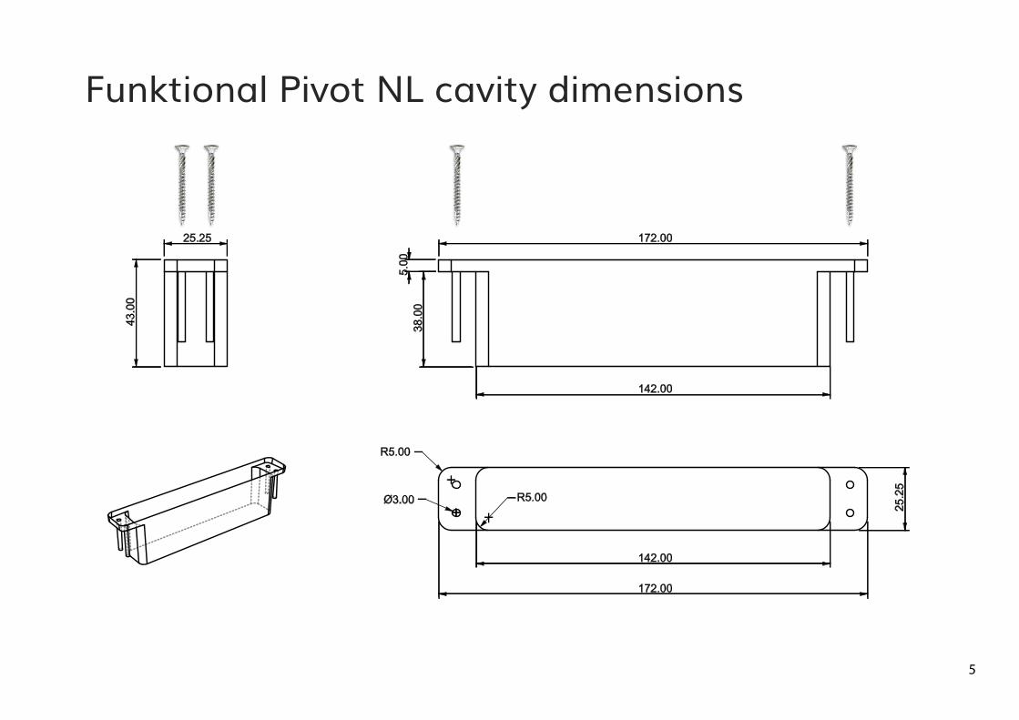
38.0
05.
00
172.00
25.2
5
142.00
142.00
R5.00
R5.00
172.00
Ø3.00
43.0
0
25.25
Funktional Pivot NL cavity dimensions
5
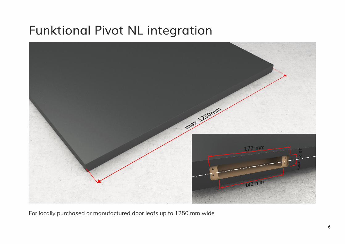
For locally purchased or manufactured door leafs up to 1250 mm wide
Funktional Pivot NL integration
6
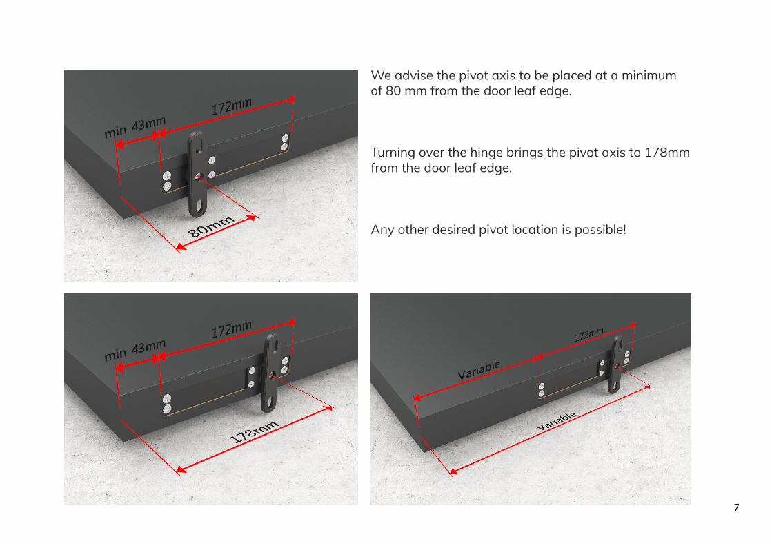
We advise the pivot axis to be placed at a minimum of 80 mm from the door leaf edge.
Turning over the hinge brings the pivot axis to 178mm from the door leaf edge.
Any other desired pivot location is possible!
7

The S90 pivot stop guarantees a door operation of 180° and blocks the door from opening further than +90° or -90°
For unlimited 360° rotation, simply remove the S90 stop.
360° advised for StealthPivotin a central axis setup
Standard for all axis positions
S90 accessory
8
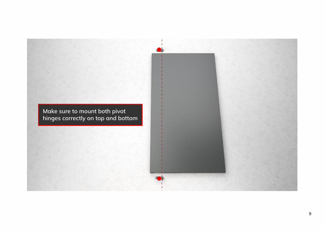
Make sure to mount both pivot hinges correctly on top and bottom
9
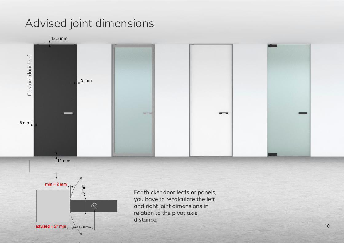
advised = 5* mm
min = 2 mm
50 m
m
axis ≥ 80 mm
5 mm
12,5 mm
11 mm
5 mm
Cust
om d
oor l
eaf
For thicker door leafs or panels, you have to recalculate the left and right joint dimensions in relation to the pivot axis distance.
Advised joint dimensions
10
Hei
ght f
rom
piv
ot to
piv
ot in
doo
rway
Hei
ght f
rom
piv
ot to
piv
ot o
n do
or
diffe
renc
edi
ffere
nce
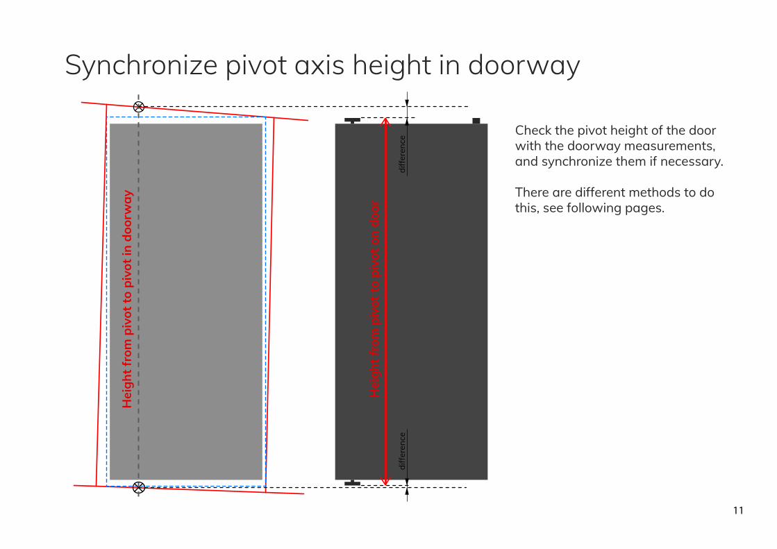
Check the pivot height of the door with the doorway measurements, and synchronize them if necessary.
There are different methods to do this, see following pages.
Synchronize pivot axis height in doorway
11
11 mm
DOOR
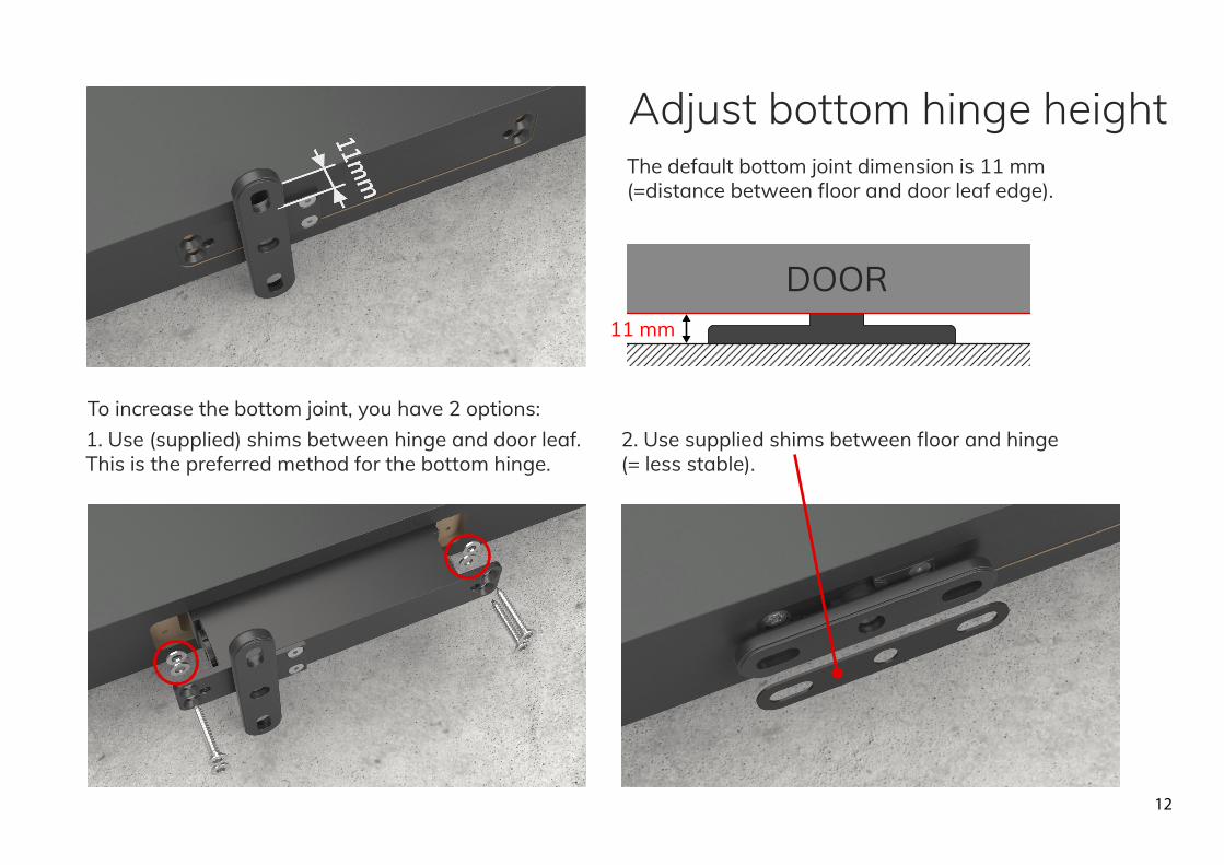
The default bottom joint dimension is 11 mm (=distance between floor and door leaf edge).
To increase the bottom joint, you have 2 options:2. Use supplied shims between floor and hinge(= less stable).
1. Use (supplied) shims between hinge and door leaf.This is the preferred method for the bottom hinge.
Adjust bottom hinge height
12
12,5 mm
DOOR
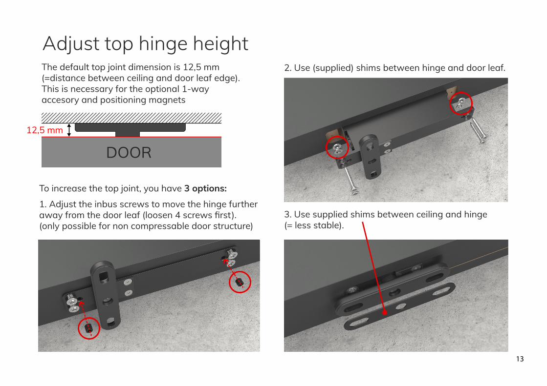
The default top joint dimension is 12,5 mm (=distance between ceiling and door leaf edge).This is necessary for the optional 1-way accesory and positioning magnets
3. Use supplied shims between ceiling and hinge(= less stable).
2. Use (supplied) shims between hinge and door leaf.
To increase the top joint, you have 3 options:
1. Adjust the inbus screws to move the hinge further away from the door leaf (loosen 4 screws first).(only possible for non compressable door structure)
Adjust top hinge height
13
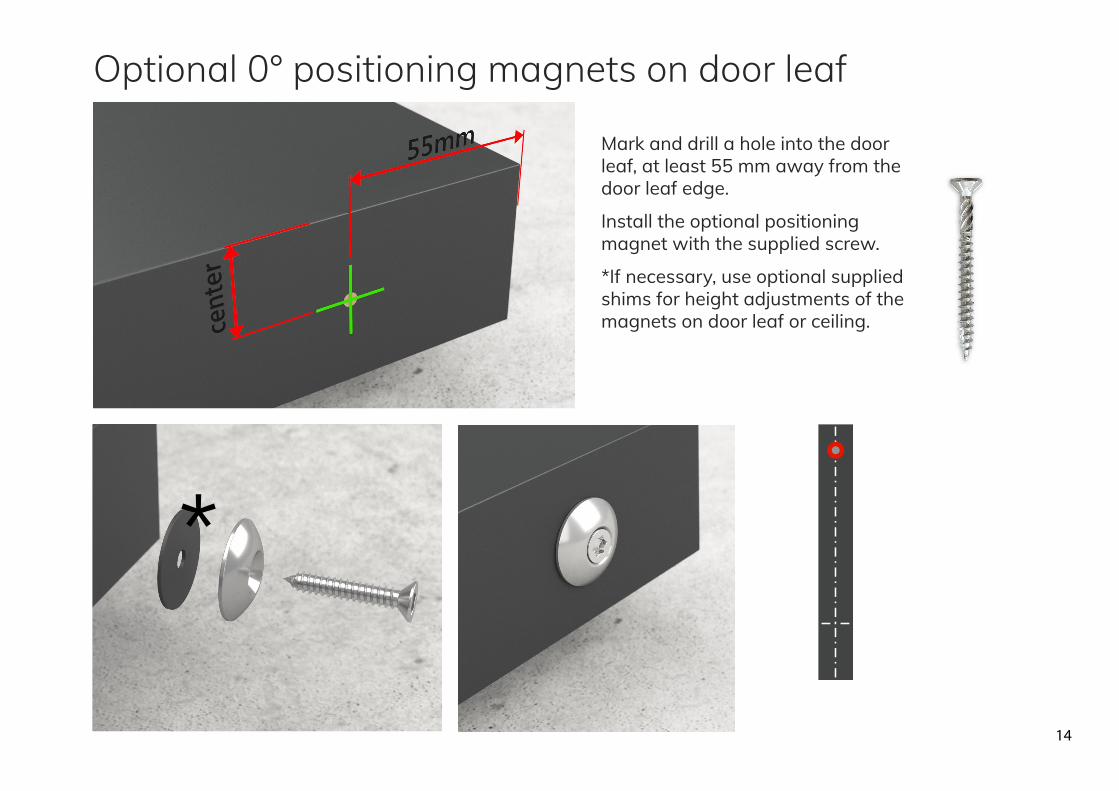
Mark and drill a hole into the door leaf, at least 55 mm away from the door leaf edge.
Install the optional positioning magnet with the supplied screw.
*If necessary, use optional supplied shims for height adjustments of the magnets on door leaf or ceiling.
Optional 0° positioning magnets on door leaf
14

check 1-way orientation
Mark and drill the holes for the 1-way part into the door leaf according to pattern below:
Install the optional 1-way under the magnet with the supplied screw.
*If necessary, use optional supplied shims for height adjustments of the magnets on door leaf or ceiling.
If you cut away both columns, you only need to drill the center hole (=less stable!)
Optional 1-way on door leaf
15 m
m
16.5 mm
50 mm
16.5 mm
Ø6 mm
Ø4 mm
15

The pivot closing force can be adjusted by changing the default gas springs.
Screw off the end cap, remove the gas springs and replace it.
Screw the cap back on.
SDefault = 2x 300N
Adjustable closing force
16
For further instructions on how to installthe fully assembled door in your doorway,
please refer to the DOOR INSTALLATION MANUAL
17