Embed Size (px)
Citation preview
Bulletin of the Transilvania University of Braşov • Vol. 10 (59) Special Issue No. 1 - 2017Series I: Engineering Sciences
ASPECTS REGARDING THE METHODS OFDESIGN OF BURIED CORRUGATED
STEEL
T.F. GALATANU1 D. RADU1
Abstract: Structures of corrugated plate are becoming widely used forroad and railway bridges construction, as well as for other transportationobjects such as culverts and pipes. Due to the fact that such bridge structuresare made of thin corrugated plates (2–7 mm) and that they are often locatedunder main roads (characterised by heavy moving loads), it is necessary toknow the methods of design and verification of these structures. Importantaspects of design are those on the interaction of the backfill structure. In thecurrent context of infrastructure development in Romania, the use of thesetypes of structures is not very common. This paper presents the designsmethods and the specific aspects of a few methods.
Key words: corrugated steel structures, design method.
1. Introduction
The corrugated steel pipe (CSP) provides a strong, durable, economical selection forthe construction of sewer systems. Introduced by a city engineer in 1896, countless milesof CSP now provide reliable service throughout the highway system and in large andsmall municipalities across the North American continent. Since 2010 on the Romanianinfrastructure branch there have been developed companies that offered considerablealternatives to concrete bridges and concrete structures, such as corrugated steelstructures.
The sewer designer can select from a wide range of corrugated steel products to meetexacting job requirements. Factory-made pipe, in sizes large enough to accommodatemost needs, is available with a variety of corrugation profiles that provide optimalstrength. For larger structures, structural plate pipe can be furnished for bolted assemblyin the field [1]. Shop fabricated fittings, long lightweight sections, reliable and positivecoupling systems—all contribute to speed and economy in field installation.
In addition, a range of protective coatings is available to meet rigorous servicedemands. On the other hand, the assembly of these types of structures is easy and doesnot require big cranes or highly qualified workers.
2. Description of the Steel Structure
1 Faculty of Civil Engineering, Transilvania University of Braşov

Bulletin of the Transilvania University of Braşov • Vol. 10 (59), Special Issue No. 1 - 201778
Depending on their cross-sectional geometry, buried corrugated steel structures aredivided into two groups: open structures (including box and arch) structures and closedstructures.
Because of the magnitude and character of the changes in displacements and internalforces, resulting from the backfilling process and originating from the live load, boxstructures differ from the other buried corrugated steel structures. For this reason theyshould be considered as a separate group [2].
A variety of assembly techniques are available, to suit site conditions, and/or size orshape of the structure. Maintaining the design shape must be a key objective during plateassembly (Figure 1).
Fig. 1. Installation of a culvert
The characteristic feature of box structures is their small height/span proportion: H/L <0.25. Also peculiar are the shape of the shell's top part whose curvature radius is largerelative to its span: R > L, and the curvature radii of the corrugated plate in the corners,several times smaller relative to the crown: R<< R. At a small soil surcharge thickness thebox shell’s high R/L ratio is responsible for the stronger effects of the concentrated forcesgenerated by commercial vehicles, resulting in local effects in the corrugated plate [2].
2.1. Description of Loadings
The safety factors and other specific quantitative recommendations herein representgenerally accepted design practice. The design loads are: dead loads developed by theembankment of trench backfill, plus stationary superimposed surface loads, uniform orconcentrated; live loads and impact loads
Live loads can be: some percentage of the weight of vehicle, train, or aircraft movingover the pipe that is distributed through the soil to the pipe. Earthquake load is alsoconsidered.
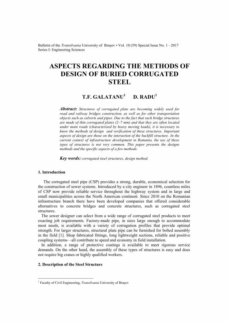
Soil-steel interaction means that a flexible steel conduit acts with the surrounding soilfill to support the loads. Modern research has shown that the ideal underground structureplaces much of the load on the soil around and over it. Corrugated steel structuresapproach this ideal condition. Load distribution is more advantageous for flexiblestructures than rigid structures (Fig. 2).
Galatanu, T.F.., et al.: Aspects Regarding the Methods of Design of Buried Corrugated Steel… 79
a) Flexible structure b) rigid structure
Fig. 2. Loads distribution
3. The Design Methods
The calculation principle is based on the cooperation between the steel tube and thestructural filler material. When designing a culvert, it is assumed that it has a uniformsection in the longitudinal direction of the tube. In the calculation model, one meter of awhole length can be considered the load underlying with forces acting perpendicular tothe axis of the tube.
Design methods are: Iowa formula, ring compression theory, Ontario code, AASHTO,Duncan method, Vaslestad, CHBDC, Scottish, Pettersson and Sundquist (SDM) or finitelement method (Abaqus, Plaxis, CandeCad, Ansys).
The AISI, AASHTO and CHBDC methods are all recognized for the design of soil-metal structures with a diameter or span greater than 3 m. The AISI and AASHTOmethods have been used for many years and can continue to be used unless the CHBDCis specifically required.
In 1941, Spangler M.G. published his work through to establish the original Iowaformula [3]. The resulting equation, known as the original Iowa formula, had thefollowing form:
.)0061.0( 4
3
reIErWKDx csL
(1)
where:x -horizontal diameter change;LD -time lag factor;
Wc -vertical load on pipe;r -radius of undeformed pipe;E -modulus of pipe material;I -moment of inertia of pipe wall sections;e -modulus of passive soil
The calculations in Sundquist and Pettersson method (SDM) are based on three maintheories, which were compared and calibrated with full-scale tests and used through thedesign process; these important points are summarized as follow:

Bulletin of the Transilvania University of Braşov • Vol. 10 (59), Special Issue No. 1 - 201780
• The soil culvert interaction (SCI) developed by Duncan (1978-1979)• The buckling calculations presented by Klöppel & Glock (1970)• Soil modulus for soil frictional material by Andreasson (1973)• Arching calculations developed by Vaslestad (1990)Extensive research on buried corrugated steel structures was sponsored by the AISI and
carried out at Utah State University in Logan, Utah, under the direction of Dr. Reynold K.Watkins [4].
This design method has been developed and improved to cope with the prevailingregulations and standards, where it provides ultimate capacity calculations using eitherthe Swedish standards or the European code.
Can be taken into account thrust forces and bending moments, using the maximumstress in the wall of the pipe is calculated using Navier’s equation:
ydsEd
s
sEd fW
MA
N
1
,
1
, (2)
where: sEdN , -is normal force; 1sA -cross section area; sEdM , -bending moment;
1W -section modulus.
At the ultimate limit state, a check is made on the maximum loaded section using EN1993-1-1 expression 6.61. As the plate is presumed not to deflect laterally (z-axes),χLT=1.0 and χz=1.0. Also, the additional moment Mz,Ed=Δ Mz,Ed=0 and, as the neutral axisdoes not change due to local buckling, Δ My,Ed=0.
The expression in EN 1993-1-1[5] can thus be simplified to:
1
1
,
,
1
M
RkyLT
Edyyy
M
Rky
EdM
MkN
N
(3)
1
1
,
,
1
M
RkyLT
Edyzy
M
Rkz
EdM
MkN
N
(4)
3.1. Using Finite Element Method
Using FEM involves some advantages, such as visualization of results and thus theability to understand structural behaviour. The main problem in modelling can be theanalyses of the soil-structure system.
Dedicated or custom programs can be used. For example, in Canada, several procedureshave been developed using finite element methods: CANDE (Culvert Analysis, Design)is an FHWA (Federal Highway Administration) sponsored computer program by M.Katona, et al. The SCI (Soil/Culvert Interaction) Design Method, by J. M. Duncan,utilizes design graphs and formulas based on finite element analyses [4].
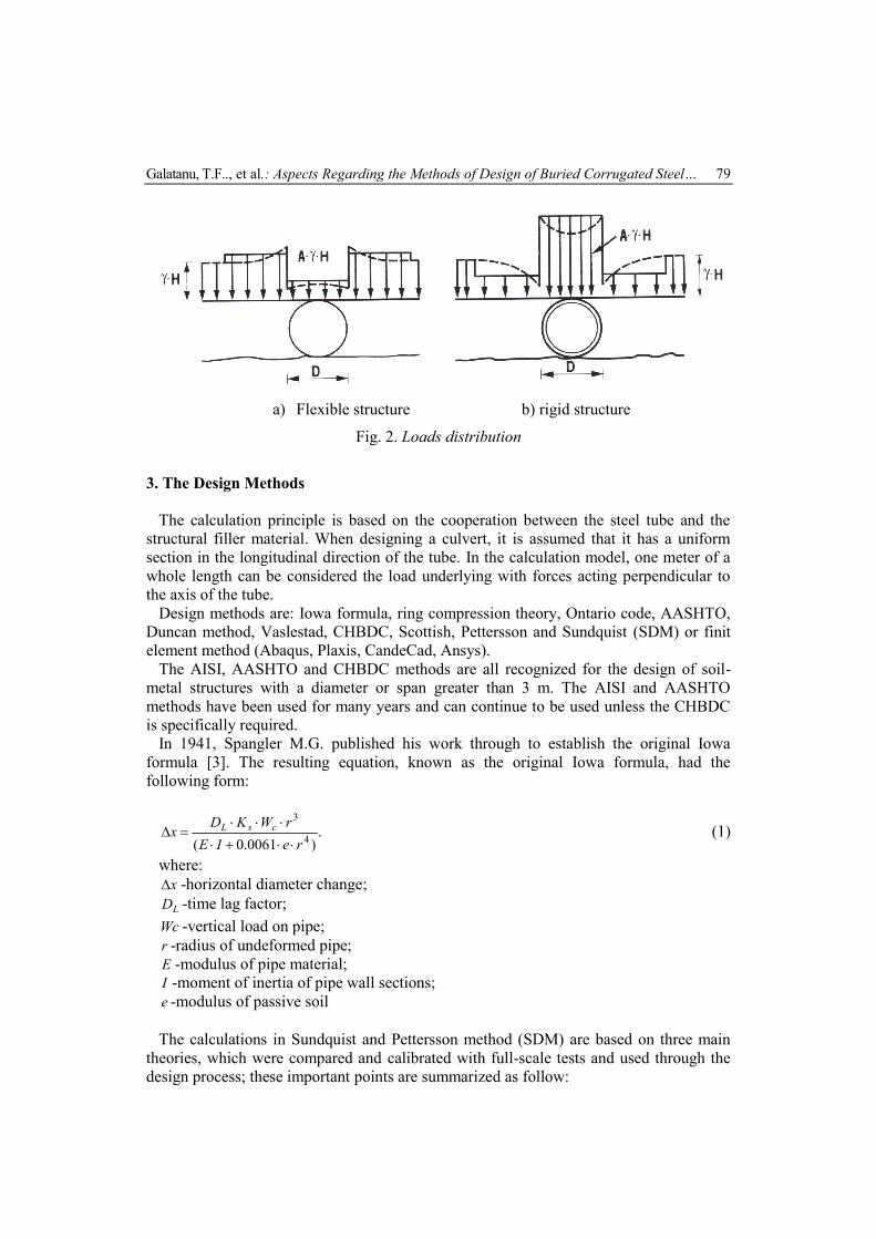
The process of designing using FEM is presented in Figure 3.
Galatanu, T.F.., et al.: Aspects Regarding the Methods of Design of Buried Corrugated Steel… 81
Fig. 3. Process of designing using FEM
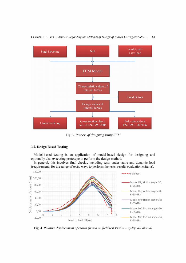
3.2. Design Based Testing
Model-based testing is an application of model-based design for designing andoptionally also executing prototype to perform the design method.
In general, this involves final checks, including tests under static and dynamic load(requirements for the range of tests, ways to perform the tests, results evaluation criteria).
Fig. 4. Relative displacement of crown (based on field test ViaCon- Rydzyna-Polonia)

Bulletin of the Transilvania University of Braşov • Vol. 10 (59), Special Issue No. 1 - 201782
4. Conclusions
Currently in Europe there is no uniform design code for buried flexible steel structures.In different countries throughout Europe there are different regulations concerning designmethods, construction and control of such structures. Currentrly in Romania, there is noimplementing specific rule of implementation for design and execution corrugated steel.
There are multiple methods to design corrugated steel plate. Similar experience and realfull-test scale certifies the applicability of these methods and encourages their use.
One of the objectives is for the investigation to establish a practical correlation betweenbackfill density and structure-behavior.
Methods of calculation and designing are chosen by the specialist engineer and mustbe made taking into account the geotechnical characteristics of the natural soil, thebackfill and the corrugated steel structure.
References
1. Galatanu, T.F.: Experimental investigation of back-to-back connected thin walled beamsbolted joints. Transilvania University Publishing Houses Brasov, 2010.
2. Machelski, C., Korusiewicz, L.: Deformation of buried corrugated metal boxstructure unde railway load, Roads and Bridges-Drogi i Mosty 166(2017) 191-201
3. Masada, T.: Modified Iowa Formula for Vertical Deflection of Buried Flexible pipe.In: Journal of Transportation Engineering, ISSN 0733-947X, 2000, p. 441-446.
4. *** Corrugated Steel Pipe Institute: Handbook of Steel Drainage and HighwayConstruction. Accessed: 09.09.2017.
5. *** SR EN 1993-1-1: Design of steel structures-Part 1-1: General rules and rules forbuildings. ASRO, 2006.
![THE INFLUENCE OF THE INPUT DATA ON UNSATURATED …webbut.unitbv.ro/BU2015/Series I/BUT_CIBv/05. Botos.pdf · earth fill [13]. The present paper will try to show the influence of available](https://img.pdfslide.us/doc/110x75/5ea68cc44784315b5120835f/the-influence-of-the-input-data-on-unsaturated-ibutcibv05-botospdf-earth.jpg)