Embed Size (px)
Citation preview

AS/NZS
AS/NZS 3000:2007 Wiring Rules(Incorporating Amendment Nos 1 and 2)
Acc
esse
d by
TA
FE
NS
W -
SY
DN
EY
INS
TIT
UT
E -
ULT
IMO
on
07 F
eb 2
013
(Doc
umen
t cur
renc
y no
t gua
rant
eed
whe
n pr
inte
d)

Wiring Rules
Acc
esse
d by
TA
FE
NS
W -
SY
DN
EY
INS
TIT
UT
E -
ULT
IMO
on
07 F
eb 2
013
(Doc
umen
t cur
renc
y no
t gua
rant
eed
whe
n pr
inte
d)

AS/NZS 3000:2007 This Joint Australian/New Zealand Standard was prepared by Joint Technical Committee EL-001, Wiring Rules. It was approved on behalf of the Council of Standards Australia on 19 October 2007 and on behalf of the Council of Standards New Zealand on 9 November 2007. This Standard was published on 12 November 2007.
The following are represented on Committee EL-001:
Association of Consulting Engineers Australia Australian Building Codes Board Australian Electrical and Electronic Manufacturers Association Canterbury Manufacturers Association New Zealand Communications, Electrical and Plumbing Union Consumers' Federation of Australia Electrical and Communications Association (Qld) Electrical Contractors Association of New Zealand Electrical Regulatory Authorities Council Electrical Safety Organisation (New Zealand) ElectroComms and Energy Utilities Industries Skills Council Energy Networks Association Engineers Australia Institute of Electrical Inspectors Ministry of Economic Development (New Zealand) National Electrical and Communications Association New Zealand Council of Elders New Zealand Electrical Institute Telstra Corporation Limited
Keeping Standards up-to-date
Standards are living documents which reflect progress in science, technology and systems. To maintain their currency, all Standards are periodically reviewed, and new editions are published. Between editions, amendments may be issued. Standards may also be withdrawn. It is important that readers assure themselves they are using a current Standard, which should include any amendments which may have been published since the Standard was purchased.
Detailed information about joint Australian/New Zealand Standards can be found by visiting the Standards Web Shop at www.saiglobal.com or Standards New Zealand web site at www.standards.co.nz and looking up the relevant Standard in the on-line catalogue.
Alternatively, both organizations publish an annual printed Catalogue with full details of all current Standards. For more frequent listings or notification of revisions, amendments and withdrawals, Standards Australia and Standards New Zealand offer a number of update options. For information about these services, users should contact their respective national Standards organization.
We also welcome suggestions for improvement in our Standards, and especially encourage readers to notify us immediately of any apparent inaccuracies or ambiguities. Please address your comments to the Chief Executive of either Standards Australia or Standards New Zealand at the address shown on the back cover.
This Standard was issued in draft form for comment as DR 06001 to DR 06010. A
cces
sed
by T
AF
E N
SW
- S
YD
NE
Y IN
ST
ITU
TE
- U
LTIM
O o
n 07
Feb
201
3 (D
ocum
ent c
urre
ncy
not g
uara
ntee
d w
hen
prin
ted)
AS/NZS 3000:2007 (Incorporating Amendment Nos 1 and 2)
Australian/New Zealand Standard™
Electrical installations (known as the Australian/New Zealand Wiring Rules)
COPYRIGHT
© Standards Australia/Standards New Zealand
All rights are reserved. No part of this work may be reproduced orcopied in any form or by any means, electronic or mechanical,including photocopying, without the written permission of the publisher,unless permitted under the Copyright Act 1968 (Australia) or theCopyright Act 1994 (New Zealand).
Jointly published by SAI Global Limited under licence from StandardsAustralia Limited, GPO Box 476, Sydney, NSW 2001 and by StandardsNew Zealand, Private Bag 2439, Wellington 6140.
ISBN 0 7337 8391 0
Originated as part of AS CC1—1931. Previous edition AS/NZS 3000:2000. Fifth edition 2007. Reissued incorporating Amendment No. 1 (July 2009). Reissued incorporating Amendment No. 2 (December 2012).
Acc
esse
d by
TA
FE
NS
W -
SY
DN
EY
INS
TIT
UT
E -
ULT
IMO
on
07 F
eb 2
013
(Doc
umen
t cur
renc
y no
t gua
rant
eed
whe
n pr
inte
d)
AS/NZS 3000:2007 2
PREFACE
This Standard was prepared by the Joint Standards Australia/Standards New Zealand Committee EL-001, Wiring Rules, to supersede, in Australia/New Zealand, AS/NZS 3000:2000, Electrical installations (known as the Australian/New Zealand Wiring Rules).
This Standard incorporates Amendment No. 1 (July 2009) and Amendment No. 2 (December 2012). The changes required by the Amendment are indicated in the text by a marginal bar and amendment number against the clause, note, table, figure or part thereof affected.
The development of this Standard has been based on the following considerations:
(a) Results of a survey of the electrical industry indicated that the industry wanted a document better suited to the present electrical regulatory structure, which flows more logically, is easier to understand, reinstates much of the guidance information removed from the 2000 edition and contains an increased level of diagrammatic representation of concepts, and more selected examples.
(b) Experience gained in the application of the eleventh (2000) edition as expressed to Standards Australia and Standards New Zealand.
During preparation of this Standard, reference was made to IEC 60364, Electrical installations of buildings (all parts) and acknowledgment is made of the assistance received from this source.
The presentation of this edition differs from previous editions of AS/NZS 3000 in that the Standard comprises two parts but with both parts bound as one document.
Part 1 provides uniform essential elements that constitute the minimum regulatory requirements for a safe electrical installation.
It also provides an alternative regulatory vehicle for Australian and New Zealand regulators seeking to move from the present prescription of AS/NZS 3000 in electrical installation safety and licensing legislation.
Part 1 satisfies the following objectives:
• It is generally complete in itself to avoid cross-referencing to Part 2.
• It may be called up in regulation as a separate Part or together with Part 2.
• It provides ‘high level’ safety performance outcomes/conditions without prescriptive work methods that demonstrate means of compliance.
• It establishes an enforcement link to Part 2. Failure to comply with a work method provision in Part 2 would breach high level safety conditions of Part 1 unless an alternative mechanism is satisfied.
• It establishes the ‘deemed to comply’ status of Part 2, confirming that installations that comply with Part 2 comply with high level safety conditions of Part 1.
A1
Acc
esse
d by
TA
FE
NS
W -
SY
DN
EY
INS
TIT
UT
E -
ULT
IMO
on
07 F
eb 2
013
(Doc
umen
t cur
renc
y no
t gua
rant
eed
whe
n pr
inte
d)

3 AS/NZS 3000:2007
• It establishes ‘deemed to comply’ status of AS/NZS 3018, relating to simple domestic applications, and parts of other standards, confirming compliance with ‘high level’ safety conditions of Part 1.
• It maintains alignment with IEC 60364 developments at the level of essential safety.
• It provides a mechanism for acceptance of alternative design and installation practices that are not addressed, or are inconsistent with, those given in the ‘deemed to comply’ Part 2. This mechanism is intended to apply where departures from the methods in Part 2 are significant rather than minor aspects that remain within the flexibility of Part 2.
• It details responsibilities, documentation and verification criteria for designers or installers that seek to apply an alternative method to the ‘deemed to comply’ methods contained in Part 2.
Part 2 provides installation practices that achieve certainty of compliance with the essential safety requirements of Part 1.
It is primarily a revision of the 2000 edition to provide work methods and installation practices that are ‘deemed to comply’ with the associated performance outcomes/safety conditions.
Part 2 satisfies the following objectives:
• It may be called up in regulation in addition to Part 1 to reflect a range of regulatory adoption options.
• It incorporates and elaborates on all ‘high level’ performance outcomes of Part 1 with the addition of requirements and recommendations to clarify and support compliance.
• It establishes the ‘deemed to comply’ status of AS/NZS 3018 relating to simple domestic applications, and parts of other standards, confirming compliance with the work methods of Part 2 and the ‘high level’ safety conditions of Part 1.
• It generally retains the structure of AS/NZS 3000:2000, except that Verification (inspection and testing) has been moved to the final section of substantive text as it would be the last function performed in the formation of an electrical installation, and damp situations have been separated from other special electrical installations as they are the more commonly occurring of special electrical installations.
• New introductory selection and installation clauses have been included in Sections 2, 3, 4, 5, 6 and 7.
• It restores information from AS 3000—1991 as requirements, recommendations and examples of typical, effective compliant solutions.
• Emphasis has been placed on common, practicable and cost-effective methods that achieve safety compliance, fitness for purpose and a level of good practice rather than overly conservative or obscure measures.
Acc
esse
d by
TA
FE
NS
W -
SY
DN
EY
INS
TIT
UT
E -
ULT
IMO
on
07 F
eb 2
013
(Doc
umen
t cur
renc
y no
t gua
rant
eed
whe
n pr
inte
d)

AS/NZS 3000:2007 4
• Greater use has been made of illustrations and examples to promote understanding of common or difficult aspects, e.g. line diagrams, alternative overcurrent device locations, International Protection (IP) rating summary, switchboard access.
• Testing and inspection provisions have been updated in alignment with AS/NZS 3017, including provisions for periodic inspection in accordance with AS/NZS 3019.
Other major changes to the content of AS/NZS 3000:2000 include the following:
(i) Revised or new definitions for—
• electrical installation;
• circuit;
• basic protection (protection against direct contact);
• fault protection (protection against indirect contact);
• outbuilding;
• isolation; and
• competent person.
(ii) Requirements for alterations, additions and repairs have been expanded and clarified through the integration of information contained in a number of frequently asked questions.
(iii) Illustration of normal and alternative location, and omission of, overcurrent devices.
(iv) Discrimination/selectivity of protective devices.
(v) A single main switch (per tariff) for a single domestic installation.
(vi) Illustration of basic clearances for switchboard access.
(vii) Expansion of the use of residual current devices (RCDs) to all socket-outlet and lighting circuits rated up to 20 A.
(viii) Limiting the number of circuits connected to any one RCD to three.
(ix) Requiring the division of lighting circuits between RCDs where the number of both RCDs and lighting circuits exceeds one.
(x) Arc fault protection is required for all switchboards with a nominal supply rated above 800 A. It is recommended for all other switchboards.
(xi) Full-size neutral conductors are required on consumers mains, multiphase submain and final subcircuits subject to some conditions, for example overcurrent detection is fitted.
(xii) Allowance for a voltage drop of up to 7% where a substation is located on the premises.
(xiii) Installation couplers are recognised as a suitable method of connecting cables.
A2
Acc
esse
d by
TA
FE
NS
W -
SY
DN
EY
INS
TIT
UT
E -
ULT
IMO
on
07 F
eb 2
013
(Doc
umen
t cur
renc
y no
t gua
rant
eed
whe
n pr
inte
d)
5 AS/NZS 3000:2007
(xiv) The colour identification of conductors has been clarified, particularly for European alternatives for single-phase and three-phase applications.
(xv) Restrictions on cable supports in suspended ceilings.
(xvi) Additional illustrations of the protection of wiring systems near building surfaces have been included.
(xvii) Segregation from telecommunications, gas and water services has been clarified and a summary table of separation distances given.
(xviii) The location of underground cables must be marked at entry to or exit from a structure or recorded on a map.
(xix) Aerial cable clearances have been updated to distribution industry standards.
(xx) Requirements have been added for the prevention of the spread of fire.
(xxi) Requirements for clearances of recessed luminaires to combustible building material and thermal insulation have been critically revised.
(xxii) Electricity generating systems, such as engine-driven generator sets, stand-alone power systems, grid-connected inverter systems and batteries, have been moved to Section 7.
(xxiii) Illustrations of the multiple earthed neutral (MEN) system have been improved and clarification of the relationship of the MEN system to the IEC systems has been added.
(xxiv) Earthing electrode types and installation conditions have been specified.
(xxv) Main earthing conductors to be labelled at the connection to the earth electrode.
(xxvi) Requirements for MEN switchboards in outbuildings have been clarified.
(xxvii) Illustration of equipotential bonding of conductive water piping has been included.
(xxviii) Reinforced concrete slabs in a shower or bathroom must be equipotentially bonded.
(xxix) Information on earth fault-loop impedance, previously included in Section 1, has been moved to Section 5.
(xxx) Bath and shower figures have been corrected to fix the Zone 2 discrepancy in the 2000 edition and now appear with corresponding plan and elevation views on facing pages.
(xxxi) The Zone 1 horizontal dimension for spa pools and tubs with water capacity less than 5 000 L has been increased to 1.25 m, instead of 1.0 m. This dimension has been changed from AS/NZS 3000:2000 to align with the limit of arm’s reach defined in Clause 1.4.12 and Figure 1.1.
A1
A1
Acc
esse
d by
TA
FE
NS
W -
SY
DN
EY
INS
TIT
UT
E -
ULT
IMO
on
07 F
eb 2
013
(Doc
umen
t cur
renc
y no
t gua
rant
eed
whe
n pr
inte
d)

AS/NZS 3000:2007 6
(xxxii) In locations containing sauna heaters (Clause 6.5), Zone 4 (the 300 mm below the ceiling) has been removed to align with IEC 60364-7-703. Zones 1 and 3 have been extended to incorporate this area.
(xxxiii) Sanitization operations have been added to hosing-down operations to clearly cover food-handling and produce areas, such as chicken farms, where corrosive chemicals are used in the cleaning and hosing-down process.
(xxxiv) Hosing-down zones have been modified.
(xxxv) ‘Emergency systems’ have been renamed ‘Safety services’ in line with IEC 60364.
(xxxvi) Generating systems are dealt with in greater detail, particularly in the areas of the suitability of RCDs with respect to waveforms of the supply and to the connection to an electrical installation. Illustration is provided for generator supply interconnection.
(xxxvii) Electrical separation is dealt with in greater detail with a new requirement for double pole switching, the provision of testing requirements in addition to those of Section 8 and the inclusion of illustrations.
(xxxviii) Separation of extra-low voltage (ELV) circuits from live parts of other circuits [both separated extra-low voltage (SELV) and protected extra-low voltage (PELV)] and earth (SELV only) must be verified by insulation resistance testing.
(xxxix) The requirements for high voltage installations (Clause 7.6) have been substantially reduced and provide a pointer to AS 2067 and the New Zealand Electricity (Safety) Regulations 2010.
(xl) Reference to other Standards and documents has been clarified to highlight their status. Specific electrical installation Standards are now grouped as—
(A) providing additional requirements that have to be complied with;
(B) deemed to comply Standards; and
(C) Standards providing guidance for specific electrical installations.
(xli) AS/NZS 3012, Electrical installations—Construction and demolition sites, and AS/NZS 3003, Electrical installations—Patient areas of hospitals and medical, dental practices and dialyzing locations, have been elevated from the status of guidance Standards to that of Standards providing additional requirements that have to be complied with.
(xlii) Verification of operation of RCDs where supply is connected is now mandatory in Australia.
(xliii) Verification of earth fault-loop impedance for socket-outlet circuits not protected by an RCD is now a mandatory test for both Australia and New Zealand.
A1
A2
Acc
esse
d by
TA
FE
NS
W -
SY
DN
EY
INS
TIT
UT
E -
ULT
IMO
on
07 F
eb 2
013
(Doc
umen
t cur
renc
y no
t gua
rant
eed
whe
n pr
inte
d)

7 AS/NZS 3000:2007
(xliv) The date of initial energization of an installation is required to be available on-site.
(xlv) Appendix B has been renamed ‘Circuit protection guide’ to reflect its content more accurately. It has been expanded to provide illustration of circuit arrangements of an installation, guidance information on automatic disconnection of supply as an introduction to the treatment of earth fault-loop impedance and a better illustration of an MEN system with earth fault-loop. Table B4.1 of the 2000 edition, Maximum values of earth fault-loop impedance (Zs) at 230 V a.c., has been relocated to Section 8 Verification.
(xlvi) Appendix C has been expanded to cover more than the calculation of maximum demand and the information provided on maximum demand has been clarified and updated. The Appendix has been renamed ‘Circuit arrangements’ and includes guidance information on simplified cable current ratings, simplified voltage drop calculations, the number of points connected to circuits and the number of cables that can be installed in conduits similar to that in the 1991 edition of AS 3000, but not included in AS/NZS 3000:2000.
(xlvii) Appendix D has been updated to provide more comprehensive guidance information for the construction of private aerial lines.
(xlviii) Appendix E has been added to provide some information on the electrical requirements contained in National Building Codes (the Building Code of Australia (BCA) and the New Zealand Building Code (NZBC)).
(xlix) Appendix F has been added to provide information and guidance on the installation of surge protective devices (SPDs).
(l) Appendix G has been added to provide information and guidance on the degree of protection of enclosed equipment (International Protection or IP rating).
(li) Appendix H has been added to provide information and guidance on the classification of wiring systems (WS classification).
(lii) Appendix I has been added to provide information and guidance on the ratings of overload protective devices where alterations, additions or repairs involve the use of existing conductors of an imperial size.
(liii) Appendix J has been added to provide a full listing of electrical symbols used in this Standard.
(liv) Text deleted
(lv) An improved index has been provided to make using the document more intuitive.
A2
A2
Acc
esse
d by
TA
FE
NS
W -
SY
DN
EY
INS
TIT
UT
E -
ULT
IMO
on
07 F
eb 2
013
(Doc
umen
t cur
renc
y no
t gua
rant
eed
whe
n pr
inte
d)
AS/NZS 3000:2007 8
(lvi) The electric shock survival (resuscitation) guide has been updated to incorporate current practice. It is, however, only provided for guidance. Persons associated with the installation and repair of electrical installations and electrical equipment should obtain training in resuscitation methods.
This Standard may be applied through legislative requirements, as indicated in Clause 1.2. As this Standard supersedes AS/NZS 3000:2000, it would usually apply to electrical installations from its date of publication, but it is recommended that it not be applied on a mandatory basis before a date at least six months after publication. However, if work on an installation was commenced before publication of this edition, the relevant regulatory authority or electricity distributor may grant permission for the installation to be completed in accordance with AS/NZS 3000:2000.
Statements expressed in mandatory terms in notes to tables and figures are deemed to be requirements of this Standard.
The term, ‘informative’ has been used in this Standard to define the application of the appendix to which it applies. An ‘informative’ appendix is only for information and guidance.
Acc
esse
d by
TA
FE
NS
W -
SY
DN
EY
INS
TIT
UT
E -
ULT
IMO
on
07 F
eb 2
013
(Doc
umen
t cur
renc
y no
t gua
rant
eed
whe
n pr
inte
d)

9 AS/NZS 3000:2007
CONTENTS
Page
FOREWORD ................................................................................................ 19
Part 1: Scope, application and fundamental principles
SECTION 1 SCOPE, APPLICATION AND FUNDAMENTAL PRINCIPLES 1.1 SCOPE ............................................................................................. 21 1.2 APPLICATION .................................................................................. 21 1.3 REFERENCED DOCUMENTS ......................................................... 22 1.4 DEFINITIONS ................................................................................... 22 1.5 FUNDAMENTAL PRINCIPLES ......................................................... 39 1.6 DESIGN OF AN ELECTRICAL INSTALLATION ............................... 51 1.7 SELECTION AND INSTALLATION OF ELECTRICAL
EQUIPMENT .................................................................................... 52 1.8 VERIFICATION (INSPECTION AND TESTING) ............................... 54 1.9 MEANS OF COMPLIANCE ............................................................... 54
Part 2: Installation practices—Sections 2 to 8
SECTION 2 GENERAL ARRANGEMENT, CONTROL AND PROTECTION 2.1 GENERAL ........................................................................................ 58 2.2 ARRANGEMENT OF ELECTRICAL INSTALLATION ....................... 58 2.3 CONTROL OF ELECTRICAL INSTALLATION .................................. 62 2.4 FAULT PROTECTION ..................................................................... 74 2.5 PROTECTION AGAINST OVERCURRENT ...................................... 75 2.6 ADDITIONAL PROTECTION BY RESIDUAL CURRENT
DEVICES ......................................................................................... 98 2.7 PROTECTION AGAINST OVERVOLTAGE .................................... 105 2.8 PROTECTION AGAINST UNDERVOLTAGE .................................. 106 2.9 SWITCHBOARDS .......................................................................... 107
SECTION 3 SELECTION AND INSTALLATION OF WIRING SYSTEMS 3.1 GENERAL ...................................................................................... 120 3.2 TYPES OF WIRING SYSTEMS ...................................................... 120 3.3 EXTERNAL INFLUENCES ............................................................. 123 3.4 CURRENT-CARRYING CAPACITY ................................................ 126 3.5 CONDUCTOR SIZE ....................................................................... 129 3.6 VOLTAGE DROP ........................................................................... 131 3.7 ELECTRICAL CONNECTIONS ...................................................... 132 3.8 IDENTIFICATION ........................................................................... 136 3.9 INSTALLATION REQUIREMENTS ................................................. 140 3.10 ENCLOSURE OF CABLES............................................................. 156 3.11 UNDERGROUND WIRING SYSTEMS ........................................... 159 3.12 AERIAL WIRING SYSTEMS ........................................................... 168 3.13 CABLES SUPPORTED BY A CATENARY ..................................... 174
Acc
esse
d by
TA
FE
NS
W -
SY
DN
EY
INS
TIT
UT
E -
ULT
IMO
on
07 F
eb 2
013
(Doc
umen
t cur
renc
y no
t gua
rant
eed
whe
n pr
inte
d)

AS/NZS 3000:2007 10
Page
3.14 SAFETY SYSTEMS ........................................................................ 174 3.15 BUSWAYS, INCLUDING RISING MAINS SYSTEMS ..................... 174 3.16 EARTH SHEATH RETURN (ESR) SYSTEM .................................. 175
SECTION 4 SELECTION AND INSTALLATION OF APPLIANCES AND ACCESSORIES
4.1 GENERAL ...................................................................................... 176 4.2 PROTECTION AGAINST THERMAL EFFECTS ............................ 178 4.3 CONNECTION OF ELECTRICAL EQUIPMENT ............................. 181 4.4 SOCKET-OUTLETS ....................................................................... 184 4.5GHTING EQUIPMENT AND ACCESSORIES .................................... 187 4.6 SMOKE AND FIRE DETECTORS .................................................. 195 4.7 COOKING APPLIANCES ............................................................... 195 4.8 APPLIANCES PRODUCING HOT WATER OR STEAM ................. 196 4.9 ROOM HEATERS ........................................................................... 197 4.10 ELECTRIC HEATING CABLES FOR FLOORS AND
CEILINGS AND TRACE HEATING APPLICATIONS ...................... 197 4.11 ELECTRIC DUCT HEATERS ......................................................... 199 4.12 ELECTRICITY CONVERTERS ....................................................... 199 4.13 MOTORS ........................................................................................ 203 4.14 TRANSFORMERS .......................................................................... 206 4.15 CAPACITORS ................................................................................ 207 4.16 ELECTRICAL EQUIPMENT CONTAINING LIQUID
DIELECTRICS ................................................................................ 209 4.17 BATTERIES ................................................................................... 210
SECTION 5 EARTHING ARRANGEMENTS AND EARTHING CONDUCTORS
5.1 GENERAL ...................................................................................... 213 5.2 EARTHING FUNCTIONS ............................................................... 217 5.3 EARTHING SYSTEM PARTS ......................................................... 218 5.4 EARTHING OF EQUIPMENT ......................................................... 230 5.5 EARTHING ARRANGEMENTS ...................................................... 234 5.6 EQUIPOTENTIAL BONDING .......................................................... 242 5.7 EARTH FAULT-LOOP IMPEDANCE ............................................. 250 5.8 OTHER EARTHING ARRANGEMENTS ......................................... 252
SECTION 6 DAMP SITUATIONS 6.1 GENERAL ...................................................................................... 253 6.2 BATHS, SHOWERS AND OTHER FIXED WATER
CONTAINERS ................................................................................ 254 6.3 SWIMMING POOLS, PADDLING POOLS AND SPA POOLS
OR TUBS ....................................................................................... 270 6.4 FOUNTAINS AND WATER FEATURES ......................................... 280 6.5 SAUNAS ........................................................................................ 285 6.6 REFRIGERATION ROOMS ............................................................ 289 6.7 SANITIZATION AND GENERAL HOSING-DOWN
OPERATIONS ................................................................................ 291
Acc
esse
d by
TA
FE
NS
W -
SY
DN
EY
INS
TIT
UT
E -
ULT
IMO
on
07 F
eb 2
013
(Doc
umen
t cur
renc
y no
t gua
rant
eed
whe
n pr
inte
d)

11 AS/NZS 3000:2007
Page
SECTION 7 SPECIAL ELECTRICAL INSTALLATIONS 7.1 GENERAL ...................................................................................... 293 7.2 SAFETY SERVICES ....................................................................... 294 7.3 ELECTRICITY GENERATION SYSTEMS ...................................... 304 7.4 ELECTRICAL SEPARATION (ISOLATED SUPPLY) ...................... 315 7.5 EXTRA-LOW VOLTAGE ELECTRICAL
INSTALLATIONS ............................................................................ 320 7.6 HIGH VOLTAGE ELECTRICAL INSTALLATIONS .......................... 324 7.7 HAZARDOUS AREAS (EXPLOSIVE GAS OR
COMBUSTIBLE DUSTS) ................................................................ 326 7.8 SPECIFIC ELECTRICAL INSTALLATION STANDARDS ................ 326
SECTION 8 VERIFICATION 8.1 GENERAL ...................................................................................... 330 8.2 VISUAL INSPECTION .................................................................... 331 8.3 TESTING ........................................................................................ 333 8.4 DATE OF INITIAL ENERGISATION OF AN
INSTALLATION .............................................................................. 342
APPENDICES A REFERENCED DOCUMENTS ....................................................... 343 B CIRCUIT PROTECTION GUIDE ..................................................... 351 C CIRCUIT ARRANGEMENTS .......................................................... 366 D MINIMUM SIZES OF POSTS, POLES AND STRUTS
FOR AERIAL LINE CONDUCTORS ............................................... 401 E ELECTRICAL INSTALLATION REQUIREMENTS IN
NATIONAL BUILDING CODES ...................................................... 420 F INSTALLATION OF SURGE PROTECTIVE DEVICES ................... 425 G DEGREES OF PROTECTION OF ENCLOSED
EQUIPMENT .................................................................................. 430 H WS CLASSIFICATION OF WIRING SYSTEMS .............................. 435 I PROTECTIVE DEVICE RATINGS AND METRIC
EQUIVALENT SIZES FOR IMPERIAL CABLES USED IN ALTERATIONS ADDITIONS AND REPAIRS ............................. 443
J SYMBOLS USED IN THIS STANDARD .......................................... 446 K (Deleted) L ELECTRIC SHOCK SURVIVAL—Australia ..................................... 449 M ELECTRIC SHOCK SURVIVAL—New Zealand .............................. 451
INDEX ........................................................................................................ 446
A1
Acc
esse
d by
TA
FE
NS
W -
SY
DN
EY
INS
TIT
UT
E -
ULT
IMO
on
07 F
eb 2
013
(Doc
umen
t cur
renc
y no
t gua
rant
eed
whe
n pr
inte
d)
AS/NZS 3000:2007 12
LIST OF TABLES
Page
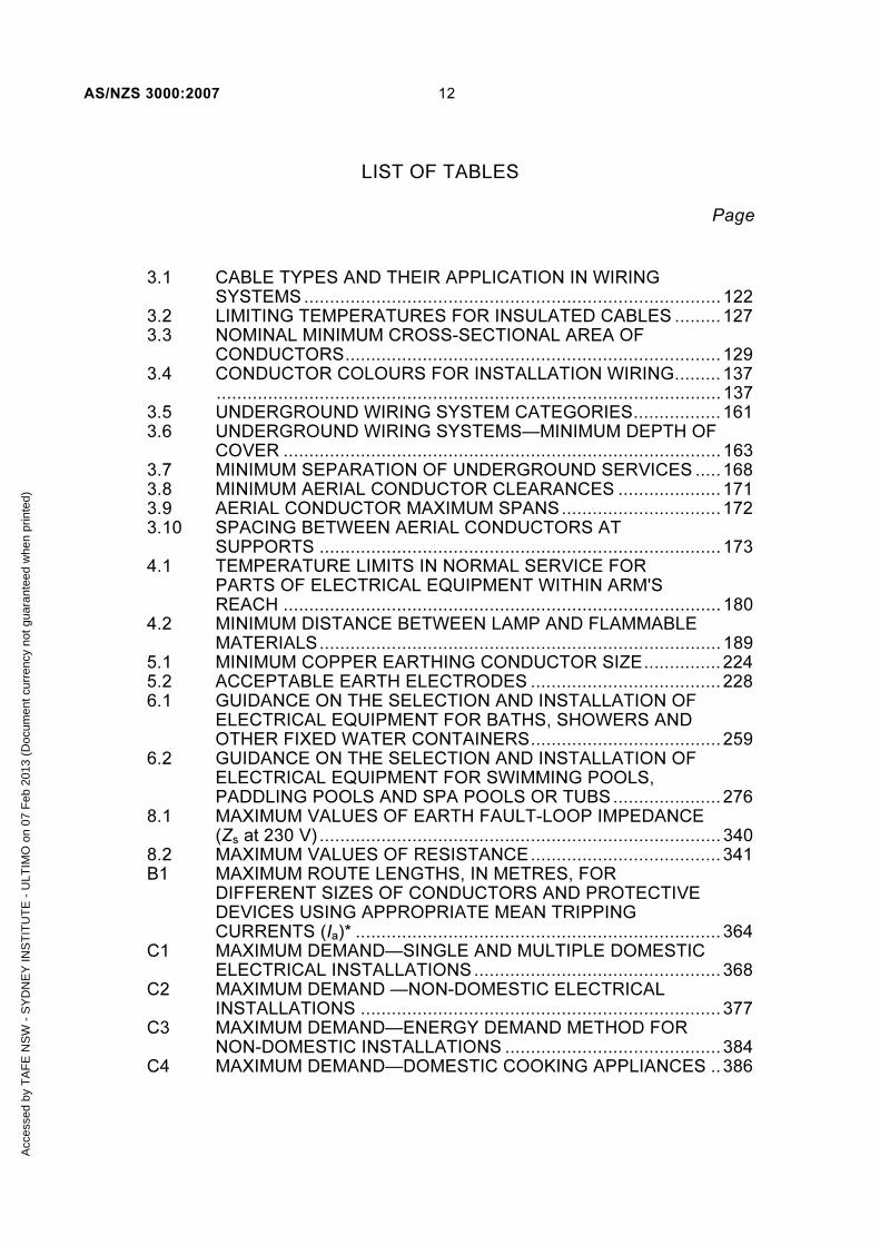
3.1 CABLE TYPES AND THEIR APPLICATION IN WIRING
SYSTEMS ................................................................................. 122 3.2 LIMITING TEMPERATURES FOR INSULATED CABLES ......... 127 3.3 NOMINAL MINIMUM CROSS-SECTIONAL AREA OF
CONDUCTORS ......................................................................... 129 3.4 CONDUCTOR COLOURS FOR INSTALLATION WIRING ......... 137
.................................................................................................. 137 3.5 UNDERGROUND WIRING SYSTEM CATEGORIES ................. 161 3.6 UNDERGROUND WIRING SYSTEMS—MINIMUM DEPTH OF
COVER ..................................................................................... 163 3.7 MINIMUM SEPARATION OF UNDERGROUND SERVICES ..... 168 3.8 MINIMUM AERIAL CONDUCTOR CLEARANCES .................... 171 3.9 AERIAL CONDUCTOR MAXIMUM SPANS ............................... 172 3.10 SPACING BETWEEN AERIAL CONDUCTORS AT
SUPPORTS .............................................................................. 173 4.1 TEMPERATURE LIMITS IN NORMAL SERVICE FOR
PARTS OF ELECTRICAL EQUIPMENT WITHIN ARM'S REACH ..................................................................................... 180
4.2 MINIMUM DISTANCE BETWEEN LAMP AND FLAMMABLE MATERIALS .............................................................................. 189
5.1 MINIMUM COPPER EARTHING CONDUCTOR SIZE ............... 224 5.2 ACCEPTABLE EARTH ELECTRODES ..................................... 228 6.1 GUIDANCE ON THE SELECTION AND INSTALLATION OF
ELECTRICAL EQUIPMENT FOR BATHS, SHOWERS AND OTHER FIXED WATER CONTAINERS ..................................... 259
6.2 GUIDANCE ON THE SELECTION AND INSTALLATION OF ELECTRICAL EQUIPMENT FOR SWIMMING POOLS, PADDLING POOLS AND SPA POOLS OR TUBS ..................... 276
8.1 MAXIMUM VALUES OF EARTH FAULT-LOOP IMPEDANCE (Zs at 230 V) .............................................................................. 340
8.2 MAXIMUM VALUES OF RESISTANCE ..................................... 341 B1 MAXIMUM ROUTE LENGTHS, IN METRES, FOR
DIFFERENT SIZES OF CONDUCTORS AND PROTECTIVE DEVICES USING APPROPRIATE MEAN TRIPPING CURRENTS (Ia)* ....................................................................... 364
C1 MAXIMUM DEMAND—SINGLE AND MULTIPLE DOMESTIC ELECTRICAL INSTALLATIONS ................................................ 368
C2 MAXIMUM DEMAND —NON-DOMESTIC ELECTRICAL INSTALLATIONS ...................................................................... 377
C3 MAXIMUM DEMAND—ENERGY DEMAND METHOD FOR NON-DOMESTIC INSTALLATIONS .......................................... 384
C4 MAXIMUM DEMAND—DOMESTIC COOKING APPLIANCES .. 386
Acc
esse
d by
TA
FE
NS
W -
SY
DN
EY
INS
TIT
UT
E -
ULT
IMO
on
07 F
eb 2
013
(Doc
umen
t cur
renc
y no
t gua
rant
eed
whe
n pr
inte
d)

13 AS/NZS 3000:2007
Page C5 SIMPLIFIED PROTECTIVE DEVICE SELECTION FOR
CABLES FROM 1 mm2 TO 25 mm2 USED IN SINGLE-PHASE APPLICATIONS ........................................................................ 388
C6 SIMPLIFIED PROTECTIVE DEVICE SELECTION FOR CABLES FROM 1 mm2 TO 25 mm2 USED IN THREE-PHASE APPLICATIONS ........................................................................ 389
C7 VOLTAGE DROP—SIMPLIFIED METHOD ............................... 391 C8 GUIDANCE ON THE LOADING OF POINTS PER FINAL
SUBCIRCUIT ............................................................................ 394 C9 GUIDE TO THE MAXIMUM NUMBER OF SINGLE-CORE
SHEATHED CABLES INSTALLED IN CONDUIT ...................... 398 C10 GUIDE TO THE MAXIMUM NUMBER OF TWO-CORE AND
EARTH CABLES INSTALLED IN CONDUIT .............................. 399 C11 GUIDE TO THE MAXIMUM NUMBER OF FOUR-CORE AND
EARTH CABLES INSTALLED IN CONDUIT .............................. 400 D1 SINKING OF POSTS/POLES IN GROUND ............................... 402 D2 FORCE EXERTED BY AERIAL LINE CONDUCTORS .............. 408 D3 SQUARE HARDWOOD POST (100 MPA TIMBER TO
AS 2209) STRENGTH RATINGS .............................................. 409 D4 SQUARE HARDWOOD STRUTS (100 MPA TIMBER TO
AS 2209) STRENGTH RATINGS .............................................. 410 D5 ROUND HARDWOOD POLE (100 MPA TIMBER TO
AS 2209) STRENGTH RATINGS—HEIGHT REDUCED FROM BASE ........................................................................................ 410
D6 ROUND HARDWOOD POLE (100 MPA TIMBER TO AS 2209) STRENGTH RATINGS—HEIGHT REDUCED FROM TOP .......................................................................................... 411
D7 ANGLE IRON STRUTS GRADE 250 STRENGTH RATINGS (CROSS-SECTION DIMENSIONS × THICKNESS (mm)) .......... 412
D8 ANGLE IRON STRUTS GRADE 300 STRENGTH RATINGS (CROSS-SECTION DIMENSIONS × THICKNESS (mm) ........... 413
D9 FABRICATED RIVERTON OCTAGONAL STEEL POLE STRENGTH RATINGS .............................................................. 413
D10 GRADE 250 STEEL-PIPE (DIAMETER × THICKNESS (mm)) STRENGTH RATINGS .............................................................. 414
D11 GRADE 350 STEEL-PIPE (DIAMETER × THICKNESS (mm)) STRENGTH RATINGS .............................................................. 415
D12(a) GRADE 350 STEEL SQUARE SECTION (WIDTH × THICKNESS (mm)) STRENGTH RATINGS ............................... 416
D12(b) GRADE 350 STEEL SQUARE SECTION (WIDTH × THICKNESS (mm)) STRENGTH RATINGS ............................... 417
D13(a) GRADE 450 STEEL SQUARE SECTION (WIDTH × THICKNESS (mm)) STRENGTH RATINGS ............................... 418
D13(b) GRADE 450 STEEL SQUARE SECTION (WIDTH × THICKNESS (mm)) STRENGTH RATINGS ............................... 419
H1 DEGREE OF PROTECTION INDICATED BY THE FIRST CHARACTERISTIC NUMERAL ................................................. 436
Acc
esse
d by
TA
FE
NS
W -
SY
DN
EY
INS
TIT
UT
E -
ULT
IMO
on
07 F
eb 2
013
(Doc
umen
t cur
renc
y no
t gua
rant
eed
whe
n pr
inte
d)
AS/NZS 3000:2007 14
Page H2 DEGREE OF PROTECTION INDICATED BY THE SECOND
CHARACTERISTIC NUMERAL ................................................. 437 I1 PROTECTIVE DEVICE RATINGS ............................................. 444 I2 SIZES OF IMPERIAL AND METRIC CABLES FOR
CONNECTION IN PARALLEL ................................................... 445 J1 SYMBOLS USED IN THIS STANDARD .................................... 447 K1 (Deleted) K2 (Deleted)
A1
Acc
esse
d by
TA
FE
NS
W -
SY
DN
EY
INS
TIT
UT
E -
ULT
IMO
on
07 F
eb 2
013
(Doc
umen
t cur
renc
y no
t gua
rant
eed
whe
n pr
inte
d)

15 AS/NZS 3000:2007
LIST OF FIGURES
Page
1.1 ZONE OF ARM’S REACH ................................................................... 24 1.2 DIRECT CONTACT ............................................................................ 27 1.3 INDIRECT CONTACT ......................................................................... 27 2.1 CLAUSES 2.5.1, 2.5.3.2 AND 2.5.4.2 GENERAL PROTECTION
ARRANGEMENT ................................................................................ 83 2.2 CLAUSE 2.5.1.3—OMISSION OF OVERCURRENT
PROTECTION FOR SAFETY REASONS ........................................... 84 2.3 CLAUSE 2.5.3.3 (a)—ALTERNATIVE POSITION OF
OVERLOAD PROTECTIVE DEVICE .................................................. 85 2.4 CLAUSE 2.5.3.3(b)—ALTERNATIVE POSITION OF
OVERLOAD PROTECTIVE DEVICE .................................................. 86 2.5 CLAUSE 2.5.3.4(b)(i)—OMISSION OF OVERLOAD
PROTECTION—CONDUCTOR ON LOAD SIDE OF A CHANGE IN CURRENT-CARRYING CAPACITY ............................................... 86
2.6 CLAUSE 2.5.3.4(b)(ii)—OMISSION OF OVERLOAD PROTECTION—FIXED LOAD NOT CAPABLE OF CAUSING AN OVERLOAD CURRENT ..................................................................... 87
2.7 CLAUSE 2.5.4.3—ALTERNATIVE POSITION OF SHORT-CIRCUIT PROTECTIVE DEVICE ....................................................... 88
2.8 CLAUSE 2.5.4.4—OMISSION OF SHORT-CIRCUIT PROTECTION .................................................................................... 88
2.9 EXAMPLE LOCATION OF PROTECTIVE DEVICE OPTIONS FOR RISING MAINS OR SUBMAIN DISTRIBUTION .......................... 89
2.10 DISCRIMINATION BETWEEN PROTECTIVE DEVICES—GENERAL .......................................................................................... 93
2.11 CIRCUIT-BREAKER CURVES—GENERAL EXPLANATION, SETTINGS AND ZONES .................................................................... 96
2.12 CIRCUIT-BREAKER CURVES WITH DISCRIMINATION REQUIREMENTS ............................................................................... 96
2.13 FUSE CURVES WITH DISCRIMINATION REQUIREMENTS ........... 97 2.14 FUSE AND CIRCUIT-BREAKER CURVES WITH
DISCRIMINATION REQUIREMENTS ................................................. 97 2.15 ACCESS TO SWITCHBOARDS—FREESTANDING
SWITCHBOARD WITH RACK-OUT SWITCHGEAR ......................... 109 2.16 ACCESS TO SWITCHBOARDS— SWITCHBOARD IN
CORNER POSITION ........................................................................ 110 2.17 ACCESS TO SWITCHBOARDS— SWITCHBOARD WITH ONE
END AGAINST WALL ....................................................................... 110 2.18 ACCESS TO SWITCHBOARDS— SWITCHBOARDS WITH
DOORS THAT OPEN INTO ACCESSWAYS OR NARROW PASSAGEWAYS .............................................................................. 111
2.19 ACCESS TO SWITCHBOARDS— FACING SWITCHBOARDS ...... 111 2.20 DELETED ....................................................................................... 115 3.1 SINGLE-PHASE CABLES ................................................................. 139 3.2 MULTI-PHASE CABLES ................................................................... 139 3.3 PROTECTION OF WIRING SYSTEMS WITHIN WALL SPACES ...... 142
Acc
esse
d by
TA
FE
NS
W -
SY
DN
EY
INS
TIT
UT
E -
ULT
IMO
on
07 F
eb 2
013
(Doc
umen
t cur
renc
y no
t gua
rant
eed
whe
n pr
inte
d)
AS/NZS 3000:2007 16
3.4 PROTECTION OF WIRING SYSTEMS WITHIN CEILINGS, FLOORS AND WALL SPACES......................................................... 143
3.5 PROTECTION OF WIRING SYSTEMS WITHIN CONCRETE ROOFS, CEILINGS OR FLOORS ..................................................... 143
3.6 PROHIBITED CABLE LOCATION—ROOF OR WALL-LINING MATERIALS ..................................................................................... 144
3.7 PROTECTION OF WIRING BELOW ROOFING MATERIAL ............. 145 3.8 SEPARATION OF LOW VOLTAGE CABLES AND
TELECOMMUNICATIONS CABLES ON SURFACES OR CONCEALED IN FLOORS OR CEILINGS ........................................ 151
3.9 SEPARATION OF LOW VOLTAGE CABLES FROM TELECOMMUNICATIONS CABLES IN UNDERGROUND TRENCHES ...................................................................................... 152
3.10 EXAMPLE OF A CATEGORY A WIRING SYSTEM WITH CABLE LOCATED BELOW POURED CONCRETE OF 75 MM MINIMUM THICKNESS .................................................................... 164
3.11 EXAMPLE OF A CATEGORY A UNDERGROUND WIRING SYSTEM WITH CABLE LOCATED BELOW NATURAL GROUND ... 164
3.12 EXAMPLE OF A CATEGORY A UNDERGROUND WIRING SYSTEM WITH CABLE LOCATED DIRECTLY BELOW POURED CONCRETE OF 75 MM MINIMUM THICKNESS WITHIN THE CONFINES OF A BUILDING ....................................... 165
3.13 EXAMPLE OF A CATEGORY B UNDERGROUND WIRING SYSTEM WITH CABLE LOCATED BELOW POURED CONCRETE OF 75 MM MINIMUM THICKNESS .............................. 165
3.14 EXAMPLE OF A CATEGORY B UNDERGROUND WIRING SYSTEM WITH CABLE LOCATED BELOW NATURAL GROUND ... 166
3.15 EXAMPLE OF A CATEGORY B UNDERGROUND WIRING SYSTEM WITH CABLE LOCATED DIRECTLY BELOW POURED CONCRETE OF 75 MM MINIMUM THICKNESS WITHIN THE CONFINES OF A BUILDING ....................................... 166
3.16 EXAMPLE OF A CATEGORY C UNDERGROUND WIRING SYSTEM ........................................................................................... 167
4.1 DIRECT CONNECTION .................................................................... 181 4.2 DIRECT CONNECTION BY INSTALLATION COUPLER .................. 182 4.3 DIRECT CONNECTION BY INSTALLATION COUPLER-
EXCEPTION ..................................................................................... 182 4.4 CONNECTION BY SOCKET-OUTLET .............................................. 182 4.5 CONNECTION BY OTHER CONNECTING DEVICES ...................... 183 4.6 EQUIPMENT WIRING–EXCEPTION FOR PENDANT SOCKET-
OUTLET ........................................................................................... 183 4.7 DEFAULT MINIMUM CLEARANCES FOR RECESSED
LUMINAIRES.................................................................................... 190 FI4.8 WARNING SIGN TO BE INSTALLED IN ACCESSIBLE ROOF
SPACES CONTAINING RECESSED LUMINAIRES ......................... 191 4.9 DEFAULT MINIMUM CLEARANCES FOR RECESSED
LUMINAIRES.................................................................................... 194 4.10 HAZARDOUS AREA PRESENTED BY A GAS CYLINDER
OUTDOORS FOR HEAVIER-THAN-AIR GASES ............................. 211
Acc
esse
d by
TA
FE
NS
W -
SY
DN
EY
INS
TIT
UT
E -
ULT
IMO
on
07 F
eb 2
013
(Doc
umen
t cur
renc
y no
t gua
rant
eed
whe
n pr
inte
d)

17 AS/NZS 3000:2007
4.11 HAZARDOUS AREA FOR RETICULATED GAS SUPPLY REGULATORS ................................................................................. 212
5.1 MULTIPLE EARTHED NEUTRAL (MEN) SYSTEM OF EARTHING—GENERAL ARRANGEMENT ....................................... 215
(Symbols are explained in Table J1.) ........................................................ 215 5.2 MULTIPLE EARTHED NEUTRAL (MEN) SYSTEM OF
EARTHING—ALTERNATIVE ARRANGEMENT ............................... 216 (Symbols are explained in Table J1.) ........................................................ 216 5.3 EXAMPLES OF EARTHING ARRANGEMENTS (CLAUSES
5.5.2.1 AND 5.5.2.2.3) ...................................................................... 237 5.4 EXAMPLES OF EQUIPOTENTIAL BONDING OF CONDUCTIVE
WATER PIPING ............................................................................... 244 5.5 EXAMPLES OF EQUIPOTENTIAL BONDING OF CONDUCTIVE
WATER PIPING (WITH EXCEPTION) .............................................. 245 6.1 BATHS AND SHOWERS, ZONE DIMENSIONS (PLAN)— BATH
WITHOUT SHOWER OR FIXED BARRIER ...................................... 260 6.2 BATHS AND SHOWERS, ZONE DIMENSIONS (ELEVATION)—
BATH WITHOUT SHOWER OR FIXED BARRIER ............................ 261 6.3 BATHS AND SHOWERS, ZONE DIMENSIONS (PLAN)—
SHOWER WITH BASE WITHOUT BARRIERS ................................. 262 6.4 BATHS AND SHOWERS, ZONE DIMENSIONS (ELEVATION)—
SHOWER WITH BASE WITHOUT BARRIERS ................................. 263 6.5 BATHS AND SHOWERS, ZONE DIMENSIONS (PLAN)— BATH
WITHOUT SHOWER WITH FIXED BARRIER .................................. 264 6.6 BATHS AND SHOWERS, ZONE DIMENSIONS (PLAN)—BATH
WITH SHOWER WITHOUT BARRIER ............................................. 265 6.7 BATHS AND SHOWERS, ZONE DIMENSIONS (PLAN)—
ENCLOSED SHOWER ..................................................................... 266 6.8 BATHS AND SHOWERS, ZONE DIMENSIONS (ELEVATION)—
SHOWER WITH BARRIER ............................................................... 267 6.9 BATHS AND SHOWERS, ZONE DIMENSIONS (PLAN)—
PARTIALLY ENCLOSED SHOWER ................................................. 268 6.10 OTHER FIXED WATER CONTAINERS WITH A CAPACITY
NOT EXCEEDING 45 L AND FIXED WATER OUTLETS, ZONE DIMENSIONS ................................................................................... 269
6.11 OTHER FIXED WATER CONTAINERS WITH A CAPACITY EXCEEDING 45 L OR WITH A FLEXIBLE WATER OUTLET, ZONE DIMENSIONS ........................................................................ 269
6.12 ZONE DIMENSIONS OF IN-GROUND SWIMMING POOLS ........... 277 6.13 ZONE DIMENSIONS OF ABOVE-GROUND SWIMMING
POOLS ............................................................................................. 277 6.14 ZONE DIMENSIONS OF SWIMMING POOLS WITH FIXED
BARRIERS (MINIMUM 1.8 M HIGH) ................................................ 278 6.15 ZONE DIMENSIONS OF IN-GROUND SPA POOLS AND TUBS
WITH WATER CAPACITY NOT EXCEEDING 5000 L ...................... 279 6.16 ZONE DIMENSIONS OF ABOVE-GROUND SPA POOLS AND
TUBS WITH WATER CAPACITY NOT EXCEEDING 5000 L ............ 280 6.17 EXAMPLE OF DETERMINATION OF THE ZONES OF A
FOUNTAIN (PLAN) ........................................................................... 284
Acc
esse
d by
TA
FE
NS
W -
SY
DN
EY
INS
TIT
UT
E -
ULT
IMO
on
07 F
eb 2
013
(Doc
umen
t cur
renc
y no
t gua
rant
eed
whe
n pr
inte
d)
AS/NZS 3000:2007 18
6.18 EXAMPLE OF DETERMINATION OF THE ZONES OF A FOUNTAIN (ELEVATION) ................................................................ 285
6.19 CLASSIFIED ZONES FOR SAUNA HEATERS ............................... 288 7.1 TYPICAL ARRANGEMENT FOR SAFETY SERVICES ..................... 300 7.2 EXAMPLE OF CONNECTION OF AN ALTERNATIVE SUPPLY
TO A SWITCHBOARD WITH A LOCAL MEN CONNECTION (THREE POLE/FOUR POLE CHANGEOVER) ................................. 310
(Symbols are explained in Table J1.) ........................................................ 310 7.3 EXAMPLE OF CONNECTION OF AN ALTERNATIVE SUPPLY
TO A SWITCHBOARD WITH A LOCAL MEN CONNECTION (THREE POLE/THREE POLE CHANGEOVER) ............................... 311
(Symbols are explained in Table J1.) ........................................................ 311 7.4 EXAMPLE OF CONNECTION OF AN ALTERNATIVE SUPPLY
TO A SWITCHBOARD WITH A LOCAL MEN CONNECTION BY MEANS OF A PLUG AND SOCKET ................................................. 312
(Symbols are explained in Table J1.) ........................................................ 312 7.5 EXAMPLE OF CONNECTION OF A GRID-CONNECTED
INVERTER ....................................................................................... 313 7.6 EXAMPLE OF CONNECTION OF A STAND-ALONE SYSTEM
TO A SWITCHBOARD WITH A LOCAL MEN CONNECTION ........... 315 (Symbols are explained in Table J1.) ........................................................ 315 7.7 SEPARATED (ISOLATED) SUPPLIES ............................................. 319 (Symbols are explained in Table J1.) ........................................................ 319 8.1 TESTING SEQUENCE ..................................................................... 334 B1 EXAMPLE OF CIRCUIT ARRANGEMENTS OF AN ELECTRICAL
INSTALLATION (TO THREE LEVELS) ............................................. 352 (Symbols are explained in Table J1.) ........................................................ 352 B2 TYPICAL OVERCURRENT PROTECTION OF CONDUCTORS ........ 353 B3 COORDINATION OF THE CHARACTERISTICS OF
CONDUCTORS AND PROTECTIVE DEVICES ................................ 354 B4 MAXIMUM DURATION OF PROSPECTIVE 50 Hz TOUCH
VOLTAGE (Reproduced from IEC/TR 61200-413 Figure C2) ........... 357 B5 MEN SYSTEM (SIMPLIFIED)—SHOWING FAULT CURRENT
(Ia) PATH (EARTH FAULT-LOOP) ................................................... 360 B6 TYPICAL TIME/CURRENT CURVES FOR CIRCUIT-BREAKERS
AND FUSES ..................................................................................... 361 D1 GUIDE TO SELECTION OF POLES/POSTS ..................................... 404 D2 GUIDE TO SELECTION OF STRUTS ............................................... 405 F1.1 PRIMARY SPD ON MAIN SWITCHBOARD .................................... 426 F1.2 SECONDARY SPD ON DISTRIBUTION BOARD............................ 427 F2 EXAMPLE OF HOW A TRANSIENT OVERVOLTAGE
DEVELOPS A HAZARDOUS VOLTAGE DIFFERENCE IN A BUILDING ........................................................................................ 428
F3 PREFERRED METHOD OF BONDING THE PRIMARY TELECOMMUNICATIONS PROTECTOR TO THE MAIN EARTH .... 429
G1 (in part) IP CODES ............................................................................ 431 G1 (in part) IP CODES ............................................................................ 432 G.2 EXAMPLE OF ‘IP’ RATING ................................................................ 434 H1 WSX1 PROTECTION BY LOCATION ............................................... 441 K1 (Deleted) A1
Acc
esse
d by
TA
FE
NS
W -
SY
DN
EY
INS
TIT
UT
E -
ULT
IMO
on
07 F
eb 2
013
(Doc
umen
t cur
renc
y no
t gua
rant
eed
whe
n pr
inte
d)

19 AS/NZS 3000:2007
FOREWORD
Application of different typefaces. There are four different typefaces used in this Standard and each of these has a specific purpose. The typefaces and their application are as follows:
(a) Bold print These are opening statements defining the fundamental principle and are generally positioned at the beginning of a clause or major part of a section.
(b) Normal print These are mandatory requirements that form the substance of a clause in that they indicate certain methods that satisfy the essential requirements.
(c) Italic print These are exceptions or variations to mandatory requirements. These generally give specific examples where the essential requirements do not apply or where they are varied for certain applications. Italic print also represents examples or clarifications given.
(d) Reduced normal print These are explanatory notes that may give advice.
They are preceded by ‘NOTE’ in the manner used in previous editions.
It is important not to read any single typeface by itself as the preceding or following paragraphs may contain additional or modifying requirements.
Cross-references Throughout this Standard, where reference to another clause or portion of a clause has been made to avoid repetition, such reference, unless otherwise stated, shall include all appropriate subclauses and paragraphs of the clause or portion thereof referred to.
Frequently asked questions (FAQs) Clarifications to requirements of the Wiring Rules that were covered by rulings and interpretations in earlier editions will be included in FAQs as the need arises. These FAQs will be applicable throughout Australia and New Zealand and will be developed by the Joint Standards Australian/Standards New Zealand Committee EL-001, Wiring Rules. These FAQs can be found online at www.wiringrules.standards.org.au.
Provision for revision This Standard necessarily deals with existing conditions, but it is not intended to discourage invention or to exclude materials, equipment and methods that may be developed. Revisions will be made from time to time in view of such developments and amendments to this edition will be made only where essential.
Special national requirements Certain provisions of the Standard have a different application in Australia and New Zealand. The following symbols appearing in the outer margin indicate that the identified Section or Clause is:
1 Applicable in Australia only.
2 Applicable in New Zealand only.
A
NZ
A2
Acc
esse
d by
TA
FE
NS
W -
SY
DN
EY
INS
TIT
UT
E -
ULT
IMO
on
07 F
eb 2
013
(Doc
umen
t cur
renc
y no
t gua
rant
eed
whe
n pr
inte
d)

AS/NZS 3000:2007 20
COPYRIGHT
STANDARDS AUSTRALIA/STANDARDS NEW ZEALAND
Australian/New Zealand Standard
Electrical installations (known as the Australian/New Zealand Wiring Rules)
Part 1: Scope, application and fundamental principles
Acc
esse
d by
TA
FE
NS
W -
SY
DN
EY
INS
TIT
UT
E -
ULT
IMO
on
07 F
eb 2
013
(Doc
umen
t cur
renc
y no
t gua
rant
eed
whe
n pr
inte
d)

21 AS/NZS 3000:2007
COPYRIGHT
S E C T I O N 1 S C O P E , A P P L I C A T I O N A N D F U N D A M E N T A L P R I N C I P L E S
1.1 SCOPE
This Standard sets out requirements for the design, construction and verification of electrical installations, including the selection and installation of electrical equipment forming part of such electrical installations.
These requirements are intended to protect persons, livestock, and property from electric shock, fire and physical injury hazards that may arise from an electrical installation that is used with reasonable care and with due regard to the intended purpose of the electrical installation.
In addition, guidance is provided so that the electrical installation will function correctly for the purpose intended.
1.2 APPLICATION
This Standard may be applied through legislative requirements, made in each State and Territory of Australia and in New Zealand, concerned with the safety of electrical installations. The Standard may also be applied in conjunction with any additional requirements, exemptions or restrictions in such legislation.
The principal application of this Standard is to electrical installations in all types of premises and land used by electricity consumers. However, the Standard may also be referenced or applied through legislative or other requirements relating to the effect of electrical installations in matters such as the following:
(a) Safety of workplaces.
NOTE: For example, Occupational Health & Safety legislation and associated codes.
(b) Safe design and construction of buildings.
NOTE: For example, National Building Codes [such as the Building Code of Australia (BCA), New Zealand Building Code (NZBC)] and the associated referenced Standards.
(c) Electricity generation, transmission and distribution systems.
(d) Safe connection to electricity distribution systems.
NOTE: For example, service rules and conditions provided by local electricity distributors.
(e) Qualifications of electricity workers.
Acc
esse
d by
TA
FE
NS
W -
SY
DN
EY
INS
TIT
UT
E -
ULT
IMO
on
07 F
eb 2
013
(Doc
umen
t cur
renc
y no
t gua
rant
eed
whe
n pr
inte
d)
AS/NZS 3000:2007 22
COPYRIGHT
Part 1 (Section 1) of this Standard provides a mechanism for acceptance of design and installation practices that may not be addressed by those given in Part 2 (Sections 2 to 8) of this Standard. This mechanism is only intended to apply where departures from the methods in Part 2 are significant.
NOTE: A degree of flexibility exists within Part 2.
1.3 REFERENCED DOCUMENTS
See Appendix A for a list of documents referred to in this Standard.
1.4 DEFINITIONS
1.4.1 Application of definitions
Throughout this Standard, the definitions of terms given in Clauses 1.4.2 to 1.4.103 apply.
Where an additional term is defined in a particular section or clause, such a term has the meaning as defined. The definitions apply to both parts of this Standard.
Exception: Where the context otherwise requires, or the word or term is not specifically defined, the commonly understood meaning shall apply. Where the terms voltage and current are used without further qualification, they imply r.m.s. values.
1.4.2 Accessible, readily
Capable of being reached quickly and without climbing over or removing obstructions, mounting upon a chair, or using a movable ladder, and in any case not more than 2.0 m above the ground, floor or platform.
1.4.3 Accessory
Any device, such as a switch, fuse, plug, socket-outlet, lampholder, fitting, adaptor or ceiling rose that is associated with wiring, luminaires, switchboards or appliances; but not including the lamps, luminaires, appliances or switchboards themselves.
1.4.4 Active (or active conductor)
Any conductor that is maintained at a difference of potential from the neutral or earthed conductor. In a system that does not include a neutral or earthed conductor, all conductors shall be considered to be active conductors.
1.4.5 Aerial conductor
Any stranded conductor (including aerial bundled conductors) that is supported by insulators or purpose-designed fittings above the ground and is directly exposed to the weather.
Alive (see Clause 1.4.63, Live part).
Acc
esse
d by
TA
FE
NS
W -
SY
DN
EY
INS
TIT
UT
E -
ULT
IMO
on
07 F
eb 2
013
(Doc
umen
t cur
renc
y no
t gua
rant
eed
whe
n pr
inte
d)

23 AS/NZS 3000:2007
COPYRIGHT
1.4.6 Appliance
A consuming device, other than a lamp, in which electricity is converted into heat, motion, or any other form of energy, or is substantially changed in its electrical character.
1.4.7 Appliance, fixed
An appliance that is fastened to a support or otherwise secured in a specific location.
1.4.8 Appliance, hand-held
A portable appliance intended to be held in the hand during normal use, the motor, if any, forming an integral part of the appliance.
1.4.9 Appliance, portable
Either an appliance that is moved while in operation or an appliance that can easily be moved from one place to another while connected to the supply.
1.4.10 Appliance, stationary
Either a fixed appliance or an appliance having a mass exceeding 18 kg and not provided with a carrying handle.
1.4.11 Area, hazardous
Area in which an explosive atmosphere is present, or may be expected to be present, in quantities such as to require special precautions for the construction, installation and use of equipment [AS/NZS 60079.0].
1.4.12 Arm’s reach
A zone extending from any point on a surface where persons usually stand or move about, to the limits that a person can reach with the hand in any direction without assistance, (e.g. tools or ladder)
(see Figure 1.1).
A2
A2
Acc
esse
d by
TA
FE
NS
W -
SY
DN
EY
INS
TIT
UT
E -
ULT
IMO
on
07 F
eb 2
013
(Doc
umen
t cur
renc
y no
t gua
rant
eed
whe
n pr
inte
d)

AS/NZS 3000:2007 24
COPYRIGHT
LEGEND:S = Sur face expected to be occupied by persons
1.25
1.251.25
2.5 2.5
0.75 0.750.75
S
S S
DIMENSIONS IN METRES
FIGURE 1.1 ZONE OF ARM’S REACH
1.4.13 Authority, regulatory
A government agency responsible for relevant legislation and its application.
1.4.14 Authorized person
The person in charge of the premises, or the licensed electrical contractor or electrician or other person appointed or selected by the person in charge of the premises to perform certain duties on the premises.
1.4.15 Available, readily
Capable of being reached for inspection, maintenance or repairs without necessitating the dismantling of structural parts, cupboards, benches or the like.
1.4.16 Barrier
A part providing basic protection from any usual direction of access.
Basic insulation (see Clause 1.4.60, Insulation system).
Basic protection (see Clause 1.4.77, Protection, basic).
1.4.17 Cable
A single cable core, or two or more cable cores laid up together, either with or without fillings, reinforcements, or protective coverings.
1.4.18 Cable, armoured
A cable provided with a wrapping of metal, usually tapes or wires, primarily for the purpose of mechanical protection.
Acc
esse
d by
TA
FE
NS
W -
SY
DN
EY
INS
TIT
UT
E -
ULT
IMO
on
07 F
eb 2
013
(Doc
umen
t cur
renc
y no
t gua
rant
eed
whe
n pr
inte
d)

25 AS/NZS 3000:2007
COPYRIGHT
1.4.19 Cable core
The conductor with its insulation but not including any mechanical protective covering.
1.4.20 Cable, flexible
A cable, the conductors, insulation and covering of which afford flexibility.
1.4.21 Cable, mineral insulated metal sheathed (MIMS)
A cable having compressed powdered mineral insulation enclosed in solid-drawn metal sheathing. Such cable may be either single-core or multi-core.
1.4.22 Cable, neutral-screened
A cable consisting of one or more cores laid up together with or without fillers, surrounded by a concentric wire outer conductor, further protected with an insulating sheath.
1.4.23 Cable, sheathed
A cable having a core or cores surrounded by a sheath.
Cable trunking (see Clause 1.4.97, Trunking, cable).
1.4.24 Ceiling, suspended
In accordance with AS/NZS 2785, a suspended ceiling is a ceiling system hung at a distance from the floor or roof above. It does not include a nailed timber ceiling complying with AS/NZS 2589.1 and timber building Standards.
1.4.25 Circuit
A circuit comprises live conductors, protective conductors (if any), a protective device and associated switchgear, controlgear and accessories.
1.4.26 Circuit-breaker
A switch suitable for opening a circuit automatically, as a result of predetermined conditions, such as those of overcurrent or undervoltage, or by some form of external control.
1.4.27 Class I equipment
Equipment in which protection against electric shock does not rely on basic insulation only, but which includes an additional safety precaution in that accessible conductive parts are connected to the protective earthing conductor in the electrical installation in such a way that accessible parts cannot become live in the event of a failure of the basic insulation.
NOTES:
1 Class I equipment may have parts with double insulation or parts operating at SELV.
2 For equipment intended for use with a flexible cord or cable, this provision includes a protective earthing conductor as part of the flexible cord or cable.
Acc
esse
d by
TA
FE
NS
W -
SY
DN
EY
INS
TIT
UT
E -
ULT
IMO
on
07 F
eb 2
013
(Doc
umen
t cur
renc
y no
t gua
rant
eed
whe
n pr
inte
d)
AS/NZS 3000:2007 26
COPYRIGHT
1.4.28 Class II equipment
Equipment in which protection against electric shock does not rely on basic insulation only, but in which additional safety precautions, such as double insulation or reinforced insulation, are provided, there being no provision for protective earthing or reliance upon installation conditions. Such equipment may be one of the following types:
(a) Equipment having durable and substantially continuous enclosures of insulating material that envelope all metal parts, with the exception of small parts, such as nameplates, screws and rivets, that are isolated from live parts by insulation at least equivalent to reinforced insulation. Such equipment is called insulation-encased Class II equipment.
(b) Equipment having a substantially continuous metal enclosure, in which double insulation is used throughout, except for those parts where reinforced insulation is used, because the application of double insulation is manifestly impracticable. Such equipment is called metal-encased Class II equipment.
(c) Equipment that is a combination of the types described in Items (a) and (b).
NOTES:
1 The enclosure of insulation-encased Class II equipment may form part of the whole of the supplementary insulation or of the reinforced insulation.
2 If the equipment with double insulation or reinforced insulation throughout has an earthing terminal or earthing contact, it is considered to be of Class I construction.
3 Class II equipment may be provided with means for maintaining the continuity of protective circuits, insulated from accessible conductive parts by double insulation or reinforced insulation.
4 Class II equipment may have parts operating at SELV.
1.4.29 Class III equipment
Equipment in which protection against electric shock relies on supply at SELV and in which voltages higher than those of SELV are not generated.
NOTE: Equipment intended to be operated at SELV and which has internal circuits that operate at a voltage other than SELV are not included in the classification and are subject to additional requirements.
1.4.30 Competent person
A person, who has acquired, through training, qualification or experience or a combination of these, the knowledge and skill enabling that person to perform the required task correctly.
1.4.31 Conductor
A wire or other form of conducting material suitable for carrying current, but not including wire or other metallic parts directly employed in converting electrical energy into another form.
Acc
esse
d by
TA
FE
NS
W -
SY
DN
EY
INS
TIT
UT
E -
ULT
IMO
on
07 F
eb 2
013
(Doc
umen
t cur
renc
y no
t gua
rant
eed
whe
n pr
inte
d)

27 AS/NZS 3000:2007
COPYRIGHT
1.4.32 Conductor, bare
A conductor without covering or insulation.
1.4.33 Consumers mains
Those conductors between the point of supply and the main switchboard.
1.4.34 Contact, direct
Contact with a conductor or conductive part that is live in normal service (see Figure 1.2. and Clause 1.4.77, Protection, basic).
1.4.35 Contact, indirect
Contact with a conductive part that is not normally live but has become live under fault conditions (because of insulation failure or some other cause) (see Figure 1.3. and Clause 1.4.78, Protection, fault).
Busbars
Is
Is : touch current
1 2 3 N
Ear th ingconductor
Is
Id
Insulat ionfa i lure
Is : touch currentId : fau l t cur rent
1 2 3
FIGURE 1.2 DIRECT CONTACT FIGURE 1.3 INDIRECT CONTACT
(Basic protection required) (Fault protection required)
1.4.36 Cord, flexible
A flexible cable, no wire of which exceeds 0.31 mm diameter and no conductor of which exceeds 4 mm2 cross-sectional area, and having not more than five cores.
1.4.37 Current, fault
A current resulting from an insulation failure or from the bridging of insulation.
1.4.38 Current, overload
An overcurrent occurring in a circuit that is electrically sound.
Acc
esse
d by
TA
FE
NS
W -
SY
DN
EY
INS
TIT
UT
E -
ULT
IMO
on
07 F
eb 2
013
(Doc
umen
t cur
renc
y no
t gua
rant
eed
whe
n pr
inte
d)

AS/NZS 3000:2007 28
COPYRIGHT
1.4.39 Current, short-circuit
A fault current resulting from a fault of negligible impedance between live conductors having a difference in potential under normal operating conditions. The fault path may include the path from active via earth to the neutral.
NOTE: This current is also referred to as ‘prospective short-circuit current’ or a ‘bolted fault’. It is the maximum value, at the relevant points for the existing installation. Unless otherwise stated, it is the three-phase r.m.s. value.
1.4.40 Damp situation
A situation in which moisture is either permanently present, or intermittently present to such an extent as would be likely to impair the effectiveness or safety of an electrical installation that complies with this Standard for ordinary situations.
Degree of protection (see Clause 1.4.61, IP Classification).
Direct contact (see Clause 1.4.34, Contact, direct).
1.4.41 Distribution board
A switchboard other than a main switchboard.
Distributor, electricity (see Clause 1.4.50, Electricity distributor).
Domestic electrical installation (see Clause 1.4.48, Electrical installation, domestic).
Double insulation (see Clause 1.4.60, Insulation system).
1.4.42 Duct
A pipe of 75 mm diameter or greater, or a closed passage formed underground or in any structure and intended to receive one or more cables that may be drawn in.
1.4.43 Earthed
Connected to both the supply neutral and the general mass of earth in accordance with the appropriate requirements of this Standard.
1.4.44 Earthed situation
A situation wherein there is a reasonable chance of a person touching exposed conductive parts and, at the same time, coming into contact with earth or with any conducting medium that may be in electrical contact with the earth or through which a circuit may be completed to earth. The following situations are deemed to be earthed situations:
(a) Within 2.5 m in any direction from a conductive floor (such as earthen, concrete, tile or brickwork flooring), permanently damp surface, metallic conduit or pipe, metallic cable sheath or armour or any other conductive material on which a person may stand.
Acc
esse
d by
TA
FE
NS
W -
SY
DN
EY
INS
TIT
UT
E -
ULT
IMO
on
07 F
eb 2
013
(Doc
umen
t cur
renc
y no
t gua
rant
eed
whe
n pr
inte
d)

29 AS/NZS 3000:2007
COPYRIGHT
(b) External to a building
Exception: An isolated piece of equipment, such as a luminaire that is mounted more than 2.5 m from the ground and from any exposed conductive part or other conductive material that is in contact with earth, is not deemed to be in an earthed situation.
(c) Within 2.5 m of the ground, floor or platform in rooms containing socket-outlets, the earthing terminals of which are earthed, and where there is a reasonable chance of a person making simultaneous contact with any exposed conductive part of electrical equipment and any exposed conductive part of an appliance connected to any of the socket-outlets.
(d) All parts of a bathroom, laundry, lavatory, toilet or kitchen.
1.4.45 Earth fault-loop impedance
The impedance of the earth fault-current loop (active-to-earth loop) starting and ending at the point-of-earth fault.
NOTE: Clause 5.7 provides a description of the constituent parts of an earth fault-current loop.
Earthing conductor
(see Clause 1.4.65, Main earthing conductor).
(see Clause 1.4.79, Protective earthing conductor).
1.4.46 Electrical equipment
Wiring systems, switchgear, controlgear, accessories, appliances, luminaires and fittings used for such purposes as generation, conversion, storage, transmission, distribution or utilization of electrical energy.
1.4.47 Electrical installation
Electrical equipment installed for the purposes of conveyance, control, measurement or use of electricity, where electricity is or is to be supplied for consumption. It includes electrical equipment supplied from a distributor’s system or a private generating system.
NOTES:
1 An electrical installation usually commences at the point of supply and finishes at a point (in wiring) but does not include portable or stationary electrical equipment connected by plug and socket-outlet (other than where a socket-outlet is used to connect sections of the fixed installation).
2 Unless the context otherwise requires, the term ‘installation’ is used to mean electrical installation.
1.4.48 Electrical installation, domestic
An electrical installation in a private dwelling or that portion of an electrical installation associated solely with a flat or living unit.
Acc
esse
d by
TA
FE
NS
W -
SY
DN
EY
INS
TIT
UT
E -
ULT
IMO
on
07 F
eb 2
013
(Doc
umen
t cur
renc
y no
t gua
rant
eed
whe
n pr
inte
d)

AS/NZS 3000:2007 30
COPYRIGHT
1.4.49 Electrical installation, multiple
An electrical installation incorporating—
(a) a number of domestic electrical installations; or
(b) a number of non-domestic electrical installations; or
(c) any combination of domestic and non-domestic electrical installations.
1.4.50 Electricity distributor
Any person or organization that provides electricity from an electricity distribution system to one or more electrical installations. Includes distributor, supply authority, network operator, local network service provider, electricity retailer or electricity entity, as may be appropriate in the relevant jurisdiction.
1.4.51 Enclosure
A part providing an appropriate degree of protection of equipment against external influences and against contact with live parts.
NOTE: AS 60529 and Appendix G provide further information on appropriate degrees of protection.
Equipment, electrical (see Clause 1.4.46, Electrical equipment).
Equipment wiring (see Clause 1.4.101, Wiring, equipment).
1.4.52 Equipotential bonding
Electrical connections intended to bring exposed conductive parts or extraneous conductive parts to the same or approximately the same potential, but not intended to carry current in normal service.
1.4.52A Explosive atmosphere
Mixture with air, under atmospheric conditions, of flammable substances in the form of gas, vapour, dust, fibres, or flyings which, after ignition, permits self-sustaining propagation. [AS/NZS 60079.0]
1.4.53 Exposed conductive part
A conductive part of electrical equipment that—
(a) can be touched with the standard test finger as specified in AS/NZS 3100; and
(b) is not a live part but can become live if basic insulation fails.
Exception: The term exposed conductive part does not apply to the following:
(i) Conductive parts within an enclosure where the parts cannot be touched unless a key or a tool is required to remove the covers of the enclosure.
(ii) Conductive parts within electrical equipment where the parts cannot be touched in normal use and movement of the electrical equipment, because of its configuration and size.
A2
Acc
esse
d by
TA
FE
NS
W -
SY
DN
EY
INS
TIT
UT
E -
ULT
IMO
on
07 F
eb 2
013
(Doc
umen
t cur
renc
y no
t gua
rant
eed
whe
n pr
inte
d)

31 AS/NZS 3000:2007
COPYRIGHT
(iii) Conductive parts that are effectively and permanently separated from live parts by—
(A) double insulation; or
(B) other conductive parts that are earthed.
(iv) Conductive parts that are in the form of nameplates, screw heads, covers and similar attachments that cannot become live in the event of failure of insulation of live parts because of the manner in which they are supported and fixed.
(v) A removable or hinged conductive panel fitted to a switchboard or other enclosure containing conductors that are so located and/or restrained that, in the event of any conductor becoming detached from a terminal or mounting, the conductor is incapable of making contact with the panel.
1.4.54 Extraneous conductive part
A conductive part that does not form part of an electrical installation but that may be at the electrical potential of a local earth.
NOTE: Examples of extraneous conductive parts include the following—
(a) metal waste, water or gas pipe from outside.
(b) cooling or heating system parts.
(c) metal or reinforced concrete building components.
(d) steel-framed structure.
(e) floors and walls of reinforced concrete without further surface treatment.
(f) tiled surfaces, conductive wall coverings.
(g) conductive fittings in washrooms, bathrooms, lavatories, toilets, etc.
(h) metallized papers.
Fault current (see Clause 1.4.37, Current, fault).
Fault protection (see Clause 1.4.78, Protection, fault).
1.4.55 Fault-current limiter
A circuit-opening device designed or selected to limit the instantaneous fault current.
Final subcircuit (see Clause 1.4.88, Subcircuit, final).
Flexible cord (see Clause 1.4.36, Cord, flexible).
1.4.56 Functional earthing (FE)
An earthing arrangement provided to ensure correct operation of electrical equipment or to permit reliable and proper functioning of electrical installations.
NOTE: ‘Clean’ (low-noise) earths provided for electrical equipment may be considered as FE. Clause 5.2.2 provides further information on FE.
A1
Acc
esse
d by
TA
FE
NS
W -
SY
DN
EY
INS
TIT
UT
E -
ULT
IMO
on
07 F
eb 2
013
(Doc
umen
t cur
renc
y no
t gua
rant
eed
whe
n pr
inte
d)

AS/NZS 3000:2007 32
COPYRIGHT
1.4.57 Fuse
A device for protecting a circuit against damage from an excessive current flowing in it by opening the circuit on the melting of the fuse-element by such excessive current. The fuse comprises all the parts that form the protective device.
Hazardous areas (see Clause 1.4.11, Area, hazardous).
Indirect contact (see Clause 1.4.35, Contact, indirect).
1.4.58 Installation coupler
A connecting device, in accordance with AS/NZS 61535, consisting of an installation socket and an installation plug designed for permanent connection and not intended to be engaged or disengaged under load (see also Clause 4.3.2.2).
Installation, electrical (see Clause 1.4.47, Electrical installation).
Installation wiring (see Clause 1.4.102, Wiring, installation).
1.4.59 Insulated
Separated from adjacent conducting material by a non-conducting substance or airspace permanently providing resistance to the passage of current, or to disruptive discharges through or over the surface of the substance or space, to obviate danger of shock or injurious leakage of current.
1.4.60 Insulation system
NOTE: The term ‘insulation system’ does not imply that the insulation must be one homogenous piece. It may comprise several layers that cannot be tested separately as supplementary or basic insulation.
One, or a combination of, the following:
(a) Basic insulation—The insulation applied to live parts, to provide basic protection against electric shock.
NOTE: Basic insulation does not necessarily include insulation used exclusively for functional purposes.
(b) Supplementary insulation—An independent insulation applied in addition to basic insulation in order to ensure protection against electric shock in the event of a failure of the basic insulation.
(c) Double insulation—Insulation comprising both basic insulation and supplementary insulation.
NOTE: Sheathed cables in accordance with the AS/NZS 5000 series, sheathed flexible cords in accordance with AS/NZS 3191 other than the ‘light duty’ type, and sheathed neutral-screened cables in accordance with AS/NZS 4961 are deemed to provide double insulation between the conductors of the cable and any conductive material in contact with the cable. The use of flexible cords of the ‘light duty’ type as supply flexible cords is covered in equipment Standards.
Acc
esse
d by
TA
FE
NS
W -
SY
DN
EY
INS
TIT
UT
E -
ULT
IMO
on
07 F
eb 2
013
(Doc
umen
t cur
renc
y no
t gua
rant
eed
whe
n pr
inte
d)

33 AS/NZS 3000:2007
COPYRIGHT
(d) Reinforced insulation—A single insulation system applied to live parts that provides a degree of protection against electric shock, equivalent to double insulation under conditions specified in AS/NZS 3100.
NOTE: Aerial bundled cables in accordance with AS/NZS 3560 are deemed to provide reinforced insulation.
1.4.61 International (ingress) protection (IP) classification
A degree of protection in accordance with AS 60529.
NOTE: Further information is provided in Appendix G.
1.4.62 Isolation (isolating function)
Function intended to cut off the supply from the whole installation, or a discrete section of it, by separating it from every source of electrical energy for reasons of safety.
Lighting fitting (see Clause 1.4.64, Luminaire).
1.4.63 Live part
A conductor or conductive part intended to be energized in normal use, including a neutral conductor and conductive parts connected to a neutral conductor.
NOTE: Under the multiple earthed neutral (MEN) earthing system this term does not apply to the following:
(a) Earthing conductors.
(b) The MEN connection and the neutral bar or link at which the MEN connection is made.
(c) The neutral bar or link in a switchboard without an MEN connection where the active supply to the switchboard has been isolated.
(d) The sheath of an MIMS cable and associated conductive fittings used as a combined protective earthing and neutral (PEN) conductor in an earth sheath return (ESR) system.
(e) Conductive supports and enclosures associated with an unprotected consumers mains that are earthed in accordance with Clause 5.5.3.5.
1.4.64 Luminaire (lighting fitting)
A complete lighting assembly intended to distribute, filter, or transform the light from one or more lamps, together with such components as ancillary and auxiliary equipment, shades, diffusers, reflectors, and accessories. Such an assembly includes the means of connection to supply circuit wiring, internal and interconnecting wiring, and any associated housings. A lampholder that is not incorporated in an assembly is not regarded as a luminaire.
1.4.65 Main earthing conductor
A conductor connecting the main earthing terminal/connection or bar to the earth electrode or to the earthing system of the source of supply.
A1
A1
A2
Acc
esse
d by
TA
FE
NS
W -
SY
DN
EY
INS
TIT
UT
E -
ULT
IMO
on
07 F
eb 2
013
(Doc
umen
t cur
renc
y no
t gua
rant
eed
whe
n pr
inte
d)

AS/NZS 3000:2007 34
COPYRIGHT
1.4.66 Multiple earthed neutral (MEN) system
A system of earthing in which the parts of an electrical installation required to be earthed in accordance with this Standard are connected together to form an equipotentially bonded network and this network is connected to both the neutral conductor of the supply system and the general mass of earth.
Multiple electrical installation (see Clause 1.4.49, Electrical installation, multiple).
1.4.67 Neutral (neutral conductor or mid-wire)
The conductor of a three-wire or multi-wire system that is maintained at an intermediate and approximately uniform potential in respect of the active or outer conductors, or the conductor of a two-wire system that is connected to earth at its origin.
Neutral-screened cable (see Clause 1.4.22, Cable, neutral-screened).
1.4.68 Obstacle
A part preventing unintentional direct contact, but not preventing direct contact by deliberate action.
1.4.69 Outbuilding
A structure completely separated by an area of land from another structure containing the switchboard from which supply is obtained.
1.4.70 Overcurrent
A current exceeding the rated value.
NOTE: For conductors, the rated value is the current-carrying capacity.
Overload current (see Clause 1.4.38, Current, overload).
1.4.71 Plug
A device intended for insertion into a socket-outlet, cord-extension socket or plug-socket adaptor to make a detachable connection between the contacts of any such accessory and the conductors of a flexible cord or flexible cable.
1.4.72 Point (in wiring)
A termination of installation wiring, intended for the connection of current using equipment.
1.4.73 Point of attachment
The point at which aerial conductors of a service line or aerial consumers mains are terminated on a consumer’s structure.
1.4.74 Point of entry
The point at which the consumers mains or the underground service cable enters a structure.
Acc
esse
d by
TA
FE
NS
W -
SY
DN
EY
INS
TIT
UT
E -
ULT
IMO
on
07 F
eb 2
013
(Doc
umen
t cur
renc
y no
t gua
rant
eed
whe
n pr
inte
d)

35 AS/NZS 3000:2007
COPYRIGHT
1.4.75 Point of supply
The junction of the consumers mains with—
(a) conductors of an electricity distribution system; or
(b) output terminals of an electricity generating system within the premises.
1.4.76 Protected extra-low voltage (PELV)
An extra-low voltage system that is not electrically separated from earth, but that otherwise satisfies all the requirements for SELV.
1.4.77 Protection, basic
Protection against dangers that may arise from direct contact with live parts of the installation (see Figure 1.2 and Clause 1.4.34, Contact, direct).
1.4.78 Protection, fault
Protection against dangers that may arise from indirect contact with live parts of the installation (contact with an exposed conductive part that is not normally live but has become live under fault conditions) (see Figure 1.3 and Clause 1.4.35, Contact, indirect).
1.4.79 Protective earthing conductor
A conductor, other than a main earthing conductor, connecting any portion of the earthing system to the portion of the electrical installation or electrical equipment required to be earthed, or to any other portion of the earthing system.
RCD (see Clause 1.4.80, Residual current device).
Readily accessible (see Clause 1.4.2, Accessible, readily).
Readily available (see Clause 1.4.15, Available, readily).
Regulatory authority (see Clause 1.4.13, Authority, regulatory).
Reinforced insulation (see Clause 1.4.60, Insulation system).
1.4.80 Residual current device (RCD)
A device intended to isolate supply to protected circuits, socket-outlets or electrical equipment in the event of a current flow to earth that exceeds a predetermined value.
1.4.81 Ripple-free d.c.
For sinusoidal ripple voltage, a ripple content not exceeding 10% r.m.s.
NOTE: The maximum peak value does not exceed 140 V for a nominal 120 V ripple-free d.c. system and 70 V for a nominal 60 V ripple-free d.c. system.
Acc
esse
d by
TA
FE
NS
W -
SY
DN
EY
INS
TIT
UT
E -
ULT
IMO
on
07 F
eb 2
013
(Doc
umen
t cur
renc
y no
t gua
rant
eed
whe
n pr
inte
d)
AS/NZS 3000:2007 36
COPYRIGHT
1.4.82 Safety service
A system or component that operates to identify an emergency, or is intended to operate during an emergency, and is primarily associated with—
(a) the safety of persons evacuating a building; or
(b) fire-fighting operations; or
(c) fire suppression.
NOTE: Examples of safety services are given in Clause 7.2.
1.4.83 Separated extra-low voltage (SELV )
An extra-low voltage system that is electrically separated from earth and from other systems in such a way that a single fault cannot give rise to the risk of electric shock.
1.4.84 Service protective device
A fuse, circuit-breaker or other device installed as required by the electricity distributor for interrupting the supply to an electrical installation on a consumers premises from the supply main.
Short-circuit current (see Clause 1.4.39, Current, short-circuit).
1.4.84A Shall
Indicates a statement is mandatory.
1.4.84B Should
Indicates a recommendation.
1.4.85 Socket, cord-extension
A device, arranged for attachment to a flexible cord, having contacts whereby a detachable connection may be made with the pins of a plug.
1.4.86 Socket-outlet
A device for fixing or suspension at a point, and having contacts intended for making a detachable connection with the contacts of a plug. The term ‘socket-outlet’ is deemed to include a cord-extension socket attached to a flexible cord that is permanently connected to installation wiring.
1.4.87 Source of supply
Where used in relation to any electrical installation, the generator, converter, transformer, etc., or group of generators, converters, or transformers, to which the supply mains conveying electricity to that particular electrical installation are connected and that generates, converts, or transforms the electrical energy so supplied to that electrical installation.
A2
Acc
esse
d by
TA
FE
NS
W -
SY
DN
EY
INS
TIT
UT
E -
ULT
IMO
on
07 F
eb 2
013
(Doc
umen
t cur
renc
y no
t gua
rant
eed
whe
n pr
inte
d)

37 AS/NZS 3000:2007
COPYRIGHT
1.4.88 Subcircuit, final
A circuit originating at a switchboard and to which only consuming devices or points will be connected. The origin of a final subcircuit is deemed to be at the connecting devices of the neutral bar or link or at the load terminals of the circuit protective devices provided within or on a switchboard specifically for the connection of the circuit. The termination of a final subcircuit is deemed to be at the supply terminals of consuming devices or points.
1.4.89 Submains
A circuit originating at a switchboard to supply another switchboard. The origin of the submains is deemed to be at the connecting devices of the neutral bar or link or at the load terminals of the circuit protective devices provided within or on a switchboard specifically for the connection of the submains. The termination of the submains is deemed to be at the supply terminals of the other switchboard.
1.4.90 Substation
An assembly of electrical equipment at one place, including any necessary housing, for the conversion or transformation of electric energy or for connection between two or more circuits.
NOTE: Measurement transformers and protection transformers are not considered to be transformers for the purpose of this Standard.
Supplementary insulation (see Clause 1.4.60, Insulation system).
Suspended ceiling (see Clause 1.4.24, Ceiling, suspended).
1.4.91 Switchboard
An assembly of circuit protective devices, with or without switchgear, instruments or connecting devices, suitably arranged and mounted for distribution to, and protection of, one or more submains or final subcircuits or a combination of both.
1.4.92 Switchboard, main
A switchboard from which the supply to the whole electrical installation can be controlled.
1.4.93 Switchgear
Equipment for controlling the distribution of electrical energy, or for controlling or protecting circuits, machines, transformers, or other equipment.
1.4.94 Touch current
Electric current that passes through a human body, or an animal body, when that body touches one or more accessible parts of electrical equipment or an electrical installation, under normal conditions or fault conditions.
Acc
esse
d by
TA
FE
NS
W -
SY
DN
EY
INS
TIT
UT
E -
ULT
IMO
on
07 F
eb 2
013
(Doc
umen
t cur
renc
y no
t gua
rant
eed
whe
n pr
inte
d)

AS/NZS 3000:2007 38
COPYRIGHT
1.4.95 Touch voltage
Voltage appearing between simultaneously accessible parts.
NOTES:
1 This term is used only in connection with fault protection.
2 In certain cases the value of the touch voltage may be appreciably influenced by the impedance of the person or livestock in contact with these parts.
1.4.96 Track system
A system of enclosed wiring comprising conductors spaced apart by, or supported on, insulating material within a channel and having plug-in facilities along its length.
Exception: This definition does not apply to busbar trunking systems (busways) complying with AS/NZS 3439.2.
1.4.97 Trunking, cable
A trunk or trough for housing and protecting electrical cables and conductors.
1.4.98 Voltage
Differences of potential normally existing between conductors or between conductors and earth as follows:
(a) Extra-low voltage: Not exceeding 50 V a.c. or 120 V ripple-free d.c.
(b) Low voltage: Exceeding extra-low voltage, but not exceeding 1 000 V a.c. or 1 500 V d.c.
(c) High voltage: Exceeding low voltage.
1.4.99 Wiring, catenary
A system of wiring consisting of a cable or cables attached at intervals to a suitable support that is suspended between two points.
1.4.100 Wiring enclosure
A pipe, tube, duct, conduit or cable trunking, fixed or supported in position in accordance with the appropriate requirements of this Standard, for the housing or protection of sheathed or unsheathed cables.
1.4.101 Wiring, equipment
All wiring of an appliance or item of electrical equipment, provided with supply terminals for the purpose of connection to an electrical installation.
1.4.102 Wiring, installation
A system of wiring in which cables are fixed or supported in position in accordance with the appropriate requirements of this Standard.
A2
Acc
esse
d by
TA
FE
NS
W -
SY
DN
EY
INS
TIT
UT
E -
ULT
IMO
on
07 F
eb 2
013
(Doc
umen
t cur
renc
y no
t gua
rant
eed
whe
n pr
inte
d)

39 AS/NZS 3000:2007
COPYRIGHT
1.4.103 Wiring, underground
A system of installation wiring in which cables are buried in soil, either directly or in a wiring enclosure beneath the surface of the ground in accordance with the appropriate requirements of this Standard.
1.5 FUNDAMENTAL PRINCIPLES
1.5.1 Protection against dangers and damage
The requirements of this Standard are intended to ensure the safety of persons, livestock, and property against dangers and damage that may arise in the reasonable use of electrical installations.
In electrical installations, the three major types of risk are as follows:
(a) Shock current Shock current arising from contact with parts that are live in normal service (direct contact) and contact with parts that become live under fault conditions (indirect contact).
NOTES:
1 A ‘shock current’ is an electric current of sufficient magnitude and duration to cause an electric shock. AS/NZS 60479 provides further information on the effects of shock current through the human body.
2 Protection under normal conditions, now designated ‘basic protection’ (referred to as ‘protection against direct contact’ in the previous edition of this Standard), is defined in Clause 1.4.77 and ‘direct contact’ is defined in Clause 1.4.34 and illustrated in Figure 1.2.
3 Protection under fault conditions, now designated ‘fault protection’ (referred to as ‘protection against indirect contact’ in the previous edition of this Standard), is defined in Clause 1.4.78 and ‘indirect contact’ is defined in Clause 1.4.35 and illustrated in Figure 1.3.
(b) Excessive temperatures Excessive temperatures likely to cause burns, fires and other injurious effects.
Persons, fixed equipment, and fixed materials adjacent to electrical equipment shall be protected against harmful effects of heat developed by electrical equipment, or thermal radiation, particularly the following effects:
(i) combustion or degradation of materials;
(ii) risk of burns;
(iii) impairment of the safe function of installed equipment.
(c) Explosive atmospheres Equipment installed in areas where explosive gases or dusts may be present shall provide protection against the ignition of such gases or dusts.
1.5.2 Control and isolation
Electrical installations shall be provided with control and isolation devices to prevent or remove hazards associated with the electrical installation and to allow maintenance of electrical equipment.
Acc
esse
d by
TA
FE
NS
W -
SY
DN
EY
INS
TIT
UT
E -
ULT
IMO
on
07 F
eb 2
013
(Doc
umen
t cur
renc
y no
t gua
rant
eed
whe
n pr
inte
d)

AS/NZS 3000:2007 40
COPYRIGHT
This may incorporate a device that effectively isolates the equipment from all sources of supply external to the equipment.
The control of safety services shall be arranged so that the control devices are separate from the control of other equipment and are not unintentionally interrupted by the operation of other equipment.
An isolation device shall interrupt all active conductors and may be required to operate in a neutral conductor.
NOTE: Clause 2.3.2.1.1 contains requirements for the operation of isolation devices in neutral conductors.
An isolation device or switch shall not interrupt an earthing conductor or a combined protective earthing and neutral (PEN) conductor.
1.5.3 Protection against electric shock
1.5.3.1 Scope
Protection shall be provided against shock current arising from contact with parts that are live in normal service (direct contact) or parts that become live under fault conditions (indirect contact).
Therefore, live parts must not be accessible and accessible conductive parts must not be live, neither under normal conditions nor under single fault conditions.
Clauses 1.5.4, 1.5.5, 1.5.6 and 1.5.7 specify essential requirements regarding protection against electric shock including basic protection and fault protection.
They also deal with the application of these requirements in relation to external influences, such as damp situations.
1.5.3.2 Methods of protection
Protection, under normal conditions, is provided by basic protective provisions and protection under single fault conditions is provided by fault protective provisions. Alternatively, protection against electric shock is provided by an enhanced protective provision that provides protection under normal conditions and under single fault conditions.
A method of protection shall consist of—
(a) an appropriate combination of a provision for basic protection and an independent provision for fault protection; or
(b) an enhanced protective provision that provides both basic protection and fault protection.
NOTE: An example of an enhanced method of protection is the use of extra-low voltage or of reinforced insulation.
Additional protection is specified as part of a method of protection under certain conditions of external influences and in certain special locations.
NOTE: Sections 6 and 7 provide guidance to conditions and special locations requiring additional protection.
Acc
esse
d by
TA
FE
NS
W -
SY
DN
EY
INS
TIT
UT
E -
ULT
IMO
on
07 F
eb 2
013
(Doc
umen
t cur
renc
y no
t gua
rant
eed
whe
n pr
inte
d)

41 AS/NZS 3000:2007
COPYRIGHT
Different methods of protection applied to the same installation or part of an installation or within equipment shall have no influence on each other such that failure of one method of protection could impair the other methods of protection.
1.5.4 Basic protection (protection against direct contact)
1.5.4.1 General
Protection shall be provided against dangers that may arise from contact with parts of the electrical installation that are live in normal service.
1.5.4.2 Methods of protection
Basic protection shall be provided by one or any combination of the following methods:
(a) Insulation, in accordance with Clause 1.5.4.3.
(b) Barriers or enclosures, in accordance with Clause 1.5.4.4.
(c) Obstacles, in accordance with Clause 1.5.4.5.
(d) Placing out of reach, in accordance with Clause 1.5.4.6.
RCDs are not recognized as a sole means of basic protection against contact with live parts but may be used to augment one of the above methods.
1.5.4.3 Protection by insulation
Live parts shall be completely covered with insulation capable of withstanding the mechanical, chemical, electrical and thermal influences to which they may be subjected in service, and that can only be removed by destruction.
NOTE: Paints, varnishes, enamels or similar products alone are not generally considered as providing adequate insulation for basic protection.
For commercially manufactured electrical equipment, the insulation shall comply with the relevant Standard for the electrical equipment.
1.5.4.4 Protection by barriers or enclosures
(a) Degree of protection Live parts shall be inside enclosures or behind barriers that provide a degree of protection of at least—
(i) IPXXB or IP2X; and
(ii) IP4X for horizontal top surfaces that are readily accessible.
NOTE: This applies in particular to parts of enclosures that might serve as a—
(A) floor; or
(B) surface where objects on surrounding surfaces may be displaced
into openings.
Larger openings are allowable in electrical equipment where they may be necessary for the proper operation and functioning of electrical
Acc
esse
d by
TA
FE
NS
W -
SY
DN
EY
INS
TIT
UT
E -
ULT
IMO
on
07 F
eb 2
013
(Doc
umen
t cur
renc
y no
t gua
rant
eed
whe
n pr
inte
d)

AS/NZS 3000:2007 42
COPYRIGHT
equipment, or where they are required for the replacement of parts, such as lamps or fuses. In such cases—
(1) suitable precautions shall be taken to prevent unintentional contact with live parts; and
(2) as far as practicable, persons shall be advised that live parts can be touched through the opening and should not be touched intentionally.
(b) Constructional requirements Barriers and enclosures shall be firmly secured in place and shall have adequate stability and strength to withstand any appreciable distortion that might be caused by the stresses likely to occur in normal operation, including external influences, so that the required degrees of protection and separation from live parts are maintained.
The removal of barriers, opening of enclosures, or withdrawal of parts of enclosures (doors, casings, lids, covers and the like) shall not be possible.
Exception: The removal of barriers is permitted where one of the following conditions apply:
(i) The use of a key or tool is required.
NOTE: Electrical equipment complying with an appropriate Standard that allows the removal of barriers or enclosures by an alternative method is not prohibited.
(ii) An interlocking device is fitted that requires—
(A) switching off, or automatic disconnection, of the supply to all live parts protected by the barrier or enclosure that might be touched accidentally during or after the removal, opening or withdrawal process; and
(B) the barrier or enclosure to be replaced or closed before the supply can normally be switched on.
NOTE: Account should be taken of danger that may exist from the stored energy of power capacitors in electrical equipment or the capacitive effect of electrical equipment, such as busways that have been isolated from the supply.
(iii) An intermediate barrier is provided that—
(A) prevents contact with all live parts when the barrier or enclosure is removed; and
(B) is permanently in position, or arranged so that it is automatically put in position when the barrier or enclosure is removed; and
(C) requires the use of a key or tool to remove.
1.5.4.5 Protection by obstacles
The method of protection ‘use of obstacles’ shall only be used in installations where access is restricted to:
Acc
esse
d by
TA
FE
NS
W -
SY
DN
EY
INS
TIT
UT
E -
ULT
IMO
on
07 F
eb 2
013
(Doc
umen
t cur
renc
y no
t gua
rant
eed
whe
n pr
inte
d)

43 AS/NZS 3000:2007
COPYRIGHT
(a) competent persons; or
(b) persons under the supervision of competent persons.
Obstacles shall prevent either—
(i) unintentional bodily approach to live parts; or
(ii) unintentional contact with live parts during the operation of live electrical equipment in normal service.
Obstacles may be removed without the use of a key or tool but shall be secured to prevent unintentional removal.
NOTE: Obstacles are intended to prevent unintentional contact with live parts but not intentional contact by deliberate circumvention of the obstacle.
1.5.4.6 Protection by placing out of reach
The method of protection ‘placing out of reach’ shall only be used in installations where access is restricted to—
(a) competent persons; or
(b) persons under the supervision of competent persons.
Simultaneously accessible parts at different voltages shall not be within arm’s reach.
NOTES:
1 Two parts are deemed to be simultaneously accessible if they are not more than 2.5 m apart.
2 Placing out of arm’s reach is intended only to prevent unintentional contact with live parts.
3 The term ‘arm’s reach’ is defined in Clause 1.4.12 and illustrated in Figure 1.1.
Where a normally occupied position is restricted in the horizontal direction by an obstacle, e.g. handrail, or mesh screen, affording a degree of protection less than IPXXB or IP2X, arm’s reach shall extend from that obstacle.
In the vertical direction, arm’s reach shall extend from the surface not taking into account any intermediate obstacle providing a degree of protection less than IPXXB or IP2X.
In places where bulky or long conductive objects are normally handled, the distances required by this Clause shall be increased to accommodate the relevant dimensions of those objects.
1.5.5 Fault protection (Protection against indirect contact)
1.5.5.1 General
Protection shall be provided against dangers that may arise from contact with exposed conductive parts that may become live under fault conditions.
In each part of an electrical installation, one or more methods of protection shall be applied, taking account of the conditions of external influence.
Acc
esse
d by
TA
FE
NS
W -
SY
DN
EY
INS
TIT
UT
E -
ULT
IMO
on
07 F
eb 2
013
(Doc
umen
t cur
renc
y no
t gua
rant
eed
whe
n pr
inte
d)

AS/NZS 3000:2007 44
COPYRIGHT
The methods of protection applied in the installation shall be considered in the selection and erection of equipment.
1.5.5.2 Methods of protection
Fault protection shall be provided by one or any combination of the following methods:
(a) Automatically disconnect the supply on the occurrence of a fault likely to cause a current flow through a body in contact with exposed conductive parts, where the value of that current is equal to or greater than the shock current, in accordance with Clause 1.5.5.3.
(b) Prevent a fault current from passing through a body by the use of Class II equipment or equivalent insulation, in accordance with Clause 1.5.5.4.
(c) Prevent a fault current from passing through a body by electrical separation of the system, in accordance with Clause 1.5.5.5.
NOTE: Clause 7.4 provides further guidance on electrical separation.
(d) Limit the fault current that can pass through a body to a value lower than the shock current.
NOTE: The most commonly used method of protection is automatic disconnection of supply.
1.5.5.3 Protection by automatic disconnection of supply
(a) General Automatic disconnection of supply is intended to limit the prospective touch voltage arising between simultaneously accessible conductive parts in the event of a fault between a live part and exposed conductive parts or a protective earthing conductor.
This method of protection shall be achieved by—
(i) provision of a system of equipotential bonding in which exposed conductive parts are connected to a protective earthing conductor; and
(ii) disconnection of the fault by a protective device.
NOTES:
1 Automatic disconnection of supply may also be required for protection against overcurrents, in accordance with Clause 1.5.9 and Clause 2.5.
2 Clause 5.6 contains requirements for equipotential bonding.
3 Section 2 contains requirements for the disconnection of a fault by a protective device.
(b) Touch-voltage limits In the event of a fault between a live part and an exposed conductive part that could give rise to a prospective touch voltage exceeding 50 V a.c. or 120 V ripple-free d.c., a protective device shall automatically disconnect the supply to the circuit or electrical equipment concerned.
NOTE: Lower touch-voltage limits are required for special electrical installations or locations according to the relevant clauses of Sections 6 and 7.
Acc
esse
d by
TA
FE
NS
W -
SY
DN
EY
INS
TIT
UT
E -
ULT
IMO
on
07 F
eb 2
013
(Doc
umen
t cur
renc
y no
t gua
rant
eed
whe
n pr
inte
d)

45 AS/NZS 3000:2007
COPYRIGHT
(c) Earthing system impedance (earth fault-loop impedance) The characteristics of protective devices and the earthing system impedance shall be such that, if a fault of negligible impedance occurs anywhere in the electrical installation between an active conductor and a protective earthing conductor or exposed conductive part, automatic disconnection of the supply will occur within the specified time.
NOTE: Clause 5.7 contains further requirements and Appendix B provides guidance regarding earth fault-loop impedance.
(d) Disconnection times The maximum disconnection time for 230/400 V supply voltage shall not exceed the following:
(i) 0.4 s for final subcircuits that supply—
(A) socket-outlets having rated currents not exceeding 63 A; or
(B) hand-held Class I equipment; or
(C) portable equipment intended for manual movement during use.
(ii) 5 s for other circuits including submains and final subcircuits supplying fixed or stationary equipment.
NOTE: Maximum disconnection times will vary for other voltages and installation conditions. Appendix B provides further guidance regarding disconnection times.
(e) Supplementary equipotential bonding Bonding of extraneous conductive parts and their connection to the earthing system may be used to reduce the earth fault-loop impedance, in order to ensure that the disconnection time of the protective device is sufficient to satisfy the requirements of Clause 1.5.5.3.(b) to (d).
NOTE: This provision does not preclude other measures, such as selection of an alternative protective device that has a lower automatic operating current (Ia) within the required disconnection time, e.g. an RCD.
1.5.5.4 Protection by the use of Class II equipment or by equivalent insulation
(a) General Protection against the occurrence of dangerous voltages on accessible conductive parts of electrical equipment in the event of a fault in the basic insulation may be achieved by one of the following means:
(i) Equipment having double or reinforced insulation (Class II equipment).
(ii) Switchgear assemblies having total insulation in accordance with AS/NZS 3439.1.
(iii) Equipment having basic insulation with appropriate supplementary insulation applied during installation.
(iv) Equipment having uninsulated live parts with appropriate reinforced insulation applied during installation.
Acc
esse
d by
TA
FE
NS
W -
SY
DN
EY
INS
TIT
UT
E -
ULT
IMO
on
07 F
eb 2
013
(Doc
umen
t cur
renc
y no
t gua
rant
eed
whe
n pr
inte
d)

AS/NZS 3000:2007 46
COPYRIGHT
Where the means of Item (iii) or (iv) is used, the additional insulation and the intended use of the electrical equipment shall provide a degree of safety equivalent to Item (i) or (ii).
NOTES:
1 Coatings, such as paint, varnish, enamel, or similar products, are not considered appropriate insulating covering for the purpose of this Clause.
2 In accordance with Clause 1.5.14, where damage to double insulation may be reasonably expected, precautions should be taken to ensure protection. Such precautions may include earthing the enclosure or RCD protection.
(b) Constructional requirements Where protection is dependent on a separate covering or enclosure providing supplementary insulation the following shall apply:
(i) Any insulating covering shall not contain any screws or bolts made of insulating material if there is a risk of impairment of the insulation by the replacement of such screws or bolts by metal screws or bolts.
(ii) Where lids or doors in any insulating enclosure can be opened without the use of a tool or key, conductive parts shall be located behind an insulating barrier that provides a degree of protection not less than IPXXB or IP2X and which shall be removable only by use of a tool.
1.5.5.5 Protection by electrical separation
Protection by electrical separation is intended, in an individual circuit, to prevent shock current through contact with exposed conductive parts that might be energized by a fault in the basic insulation of that circuit.
Live parts of a separated circuit shall not be connected at any point to earth or to another circuit.
Any protective bonding conductor associated with a separated circuit shall not be connected at any point to earth.
NOTE: Clause 7.4 contains requirements for protection by electrical separation.
1.5.6 Additional protection by the use of RCDs
1.5.6.1 Basic protection
RCDs are not recognized as a sole means of basic protection (in normal service) but may be used to augment one of the means set out in Clause 1.5.4.2.
1.5.6.2 Fault protection
RCDs are recognized as a means of providing automatic disconnection of supply in accordance with Clause 1.5.5.3.
1.5.6.3 Where required
RCDs for the limitation of earth leakage current shall be capable of interrupting the part of the circuit protected by the RCD when an earth leakage current reaches a predetermined value.
A1
Acc
esse
d by
TA
FE
NS
W -
SY
DN
EY
INS
TIT
UT
E -
ULT
IMO
on
07 F
eb 2
013
(Doc
umen
t cur
renc
y no
t gua
rant
eed
whe
n pr
inte
d)

47 AS/NZS 3000:2007
COPYRIGHT
RCDs shall be installed for additional protection of the following:
(a) Circuits, socket-outlets, lighting points and hand-held equipment as specified in Part 2, Clause 2.6.
(b) Wiring systems as specified in Part 2, Clause 3.9.4.4
(c) Electric heating cables as specified in Part 2, Clause 4.10.5.
(d) Electrical equipment, including socket-outlets, installed in damp situations as specified in Part 2, Section 6.
(e) Specific electrical installations as specified in AS/NZS 3001, AS/NZS 3002, AS/NZS 3003, AS/NZS 3004, AS/NZS 3012 and AS/NZS 4249.
NOTE: In areas where excessive earth leakage current could present a significant risk in the event of failure of other measures of protection or carelessness by users, RCDs are designed to provide additional protection against the effects of electric shock by automatically disconnecting supply before serious physical injury can occur.
1.5.7 Basic and fault protection by use of extra-low voltage
Separated extra-low voltage (SELV) or protected extra-low voltage (PELV) systems may be used to provide both basic and fault protection subject to the following conditions:
(a) The nominal voltage shall not be capable of exceeding the limits for extra-low voltage (50 V a.c. or 120 V ripple-free d.c.) and the source of supply is arranged so that it cannot exceed these values.
(b) Circuits shall be electrically segregated from each other and from circuits at higher voltages.
(c) Live parts of SELV circuits shall not be connected to earth or to protective earthing conductors that are part of other circuits or to other live parts.
(d) Live parts of PELV circuits shall be protected from direct contact by barriers or insulation unless the voltage does not exceed 25 V a.c. or 60 V ripple-free d.c. in dry areas where a large contact area with the human body is not expected or 6 V a.c. or 15 V ripple-free d.c. in all other areas.
NOTE: Clause 7.5 provides specific deemed to comply requirements for the arrangement of ELV circuits.
1.5.8 Protection against thermal effects in normal service
Electrical installations shall be arranged so that there is no risk of ignition of flammable materials because of high temperature or electric arc in normal service. During normal operation of the electrical equipment there shall be no risk of persons or livestock suffering burns.
Acc
esse
d by
TA
FE
NS
W -
SY
DN
EY
INS
TIT
UT
E -
ULT
IMO
on
07 F
eb 2
013
(Doc
umen
t cur
renc
y no
t gua
rant
eed
whe
n pr
inte
d)
AS/NZS 3000:2007 48
COPYRIGHT
The selection and installation of electrical equipment shall be such that the temperature characteristics of the electrical equipment, properly installed and operated, do not adversely affect the electrical equipment, the electrical installation itself or any other installation, whether electrical or otherwise.
Adequate ventilation shall be provided where heat is generated in normal operation in order to maintain operating temperatures below the rated or specified limits.
NOTES:
1 Account should be taken of the influence that temperature might have on the operational or characteristic values of the electrical equipment.
2 Further information on thermal effects associated with the installation of electrical equipment is given in Clause 4.2.
1.5.9 Protection against overcurrent
Protection shall be provided against injury or property damage because of excessive temperatures or electromechanical stresses caused by any overcurrents likely to arise in live conductors.
Protection may be provided by one of the following methods:
(a) Automatic disconnection on the occurrence of an overcurrent, before this overcurrent attains a dangerous value, taking into account its duration.
(b) Limiting the maximum overcurrent to a safe value and duration.
1.5.10 Protection against earth fault currents
Protective earthing conductors and any other parts intended to carry an earth fault current shall be capable of carrying that current without attaining excessive temperature.
1.5.11 Protection against abnormal voltages
1.5.11.1 General
Protection shall be provided against any harmful effects of abnormal voltages—
(a) caused by a fault between live parts of circuits supplied at different voltages; or
(b) induced or otherwise occurring in unused conductors; or
(c) occurring as a result of any harmful influence between different circuits and installations.
1.5.11.2 Circuits operating at different voltages
Protection shall be provided against injury or property damage because of any harmful effects of a fault between live parts of circuits supplied at different voltages.
Acc
esse
d by
TA
FE
NS
W -
SY
DN
EY
INS
TIT
UT
E -
ULT
IMO
on
07 F
eb 2
013
(Doc
umen
t cur
renc
y no
t gua
rant
eed
whe
n pr
inte
d)

49 AS/NZS 3000:2007
COPYRIGHT
Protection may be provided by—
(a) segregation; or
NOTE: Clause 3.9.8 provides guidance on the segregation of circuits of different voltage levels.
(b) installation of devices for protection against overvoltages.
NOTE: Clause 2.7 provides guidance on the installation of devices for protection against overvoltages.
1.5.11.3 Voltage disturbances and electromagnetic influences
Protection against damage as a consequence of overvoltage, such as that originating from lightning or from switching operations, is not a requirement of this Standard.
NOTE: Clause 2.7 and Appendix F provide guidance on overvoltage (surge) protection.
1.5.11.4 Voltage in unused conductors.
Protection shall be provided against injury or property damage because of any harmful effects of voltage that may be induced or otherwise occur in unused conductors. Disconnected, redundant or unused conductors associated with conductors that remain connected shall be terminated and protected at both ends in the same manner as is required for live conductors.
NOTE: Such conductors are capable of attaining induced, unwanted voltages that may be dangerous, particularly where in close proximity to high voltage conductors.
1.5.11.5 Different circuits and installations
Protection shall be provided against injury or property damage because of any harmful influence between—
(a) different electrical installations;
(b) different circuits of the same electrical installation;
(c) electrical and non-electrical installations; and
(d) the electrical installation and the structure in or on which it is installed.
NOTES:
1 Requirements for the enclosure of telecommunication cables with other wiring systems, including high voltage systems, are contained in AS/ACIF S009 and for New Zealand in the TCF Premises Wiring Code of Practice.
2 AS/NZS 3080 provides guidance on the effects of electrical interference to circuits, such as telecommunications and data transfer.
A2
Acc
esse
d by
TA
FE
NS
W -
SY
DN
EY
INS
TIT
UT
E -
ULT
IMO
on
07 F
eb 2
013
(Doc
umen
t cur
renc
y no
t gua
rant
eed
whe
n pr
inte
d)

AS/NZS 3000:2007 50
COPYRIGHT
1.5.12 Protection against the spread of fire
Protection shall be provided against fire initiated or propagated by components of the electrical installation.
Electrical equipment shall be selected, installed and protected such that the equipment will not—
(a) obstruct escape routes, either directly or by the products of combustion; or
(b) contribute to, or propagate a fire; or
(c) attain a temperature high enough to ignite adjacent material; or
(d) adversely affect means of egress from a structure.
NOTES:
1 Clause 2.9.2.5 (h) contains requirements for the placement of switchboards in or near fire exits and egress paths.
2 Clauses 2.9.7, 3.9.9 and Appendix E contain requirements dealing with the prevention of the spread of fire.
1.5.13 Protection against injury from mechanical movement
Protection shall be provided against injury from mechanical movement of electrically actuated equipment, where—
(a) mechanical maintenance may involve risk of physical injury; or
(b) emergency stopping may be necessary to remove any unexpected danger.
Protection may be provided by the provision of devices to disconnect or isolate electrical equipment, as may be necessary to prevent or remove danger.
1.5.14 Protection against external influences
All parts of an electrical installation shall be designed to be adequately protected against damage that might reasonably be expected from environmental and other external influences to which the electrical installation may be exposed under the conditions of its use. These conditions would be those that would be expected during normal operation.
Damage from such influences may include mechanical damage, and damage because of exposure to weather, water, flora, fauna, seismic activity, excessive dampness, corrosive fumes, galvanic action, accumulation of dust, steam, oil, temperature, explosive atmospheres, vibration or any other influence to which the electrical installation may be exposed under the conditions of its use.
Acc
esse
d by
TA
FE
NS
W -
SY
DN
EY
INS
TIT
UT
E -
ULT
IMO
on
07 F
eb 2
013
(Doc
umen
t cur
renc
y no
t gua
rant
eed
whe
n pr
inte
d)
51 AS/NZS 3000:2007
COPYRIGHT
1.6 DESIGN OF AN ELECTRICAL INSTALLATION
1.6.1 General
An electrical installation shall be designed to—
(a) protect persons, livestock and property from harmful effects;
(b) function correctly as intended;
(c) connect, operate safely and be compatible with the electricity distribution system, or other source of supply, to which the electrical installation is to be connected;
(d) minimize inconvenience in the event of a fault; and
(e) facilitate safe operation, inspection, testing and maintenance.
1.6.2 Supply characteristics
The following characteristics of the electricity supply shall be determined:
(a) Nature of current, a.c. or d.c.
(b) Nature and number of conductors, as follows:
(i) Active (phase), neutral and protective earthing conductors for a.c.
(ii) Equivalent conductors for d.c.
(c) Voltage and voltage tolerances.
NOTE: The nominal voltage and tolerances for low voltage supply systems and electrical installations are—
(a) for Australia, 230/400 V +10% to −6% (in accordance with AS 60038); and
(b) for New Zealand, 230/400 V +6% to −6% (in accordance with IEC 60038).
(d) Frequency and frequency tolerances.
(e) Maximum current that can be supplied.
(f) Prospective short-circuit current.
NOTE: Information regarding prospective short-circuit and fault currents at the point of supply may be obtained from the local electricity distributor.
(g) Protective measures inherent in the supply, e.g. MEN earthing system.
(h) Limits on the use of equipment.
(i) Harmonic current or other limitations.
1.6.3 Maximum demand
The maximum demand of an electrical installation shall be determined, taking account of the capacity, physical distribution and intended use of electrical equipment in the electrical installation and the manner in which the present requirements might vary.
Consumers mains, submains and other electrical equipment of an electrical installation shall be designed and installed to meet the maximum demand.
A
NZ
A
Acc
esse
d by
TA
FE
NS
W -
SY
DN
EY
INS
TIT
UT
E -
ULT
IMO
on
07 F
eb 2
013
(Doc
umen
t cur
renc
y no
t gua
rant
eed
whe
n pr
inte
d)

AS/NZS 3000:2007 52
COPYRIGHT
NOTE: Clause 2.2.2 contains acceptable methods of determining maximum demand.
1.6.4 Utilization voltage
The electrical installation shall be designed and installed to ensure that the voltage at the terminals of electrical appliances and equipment is suitable for the nominal operating voltage of electrical appliances and equipment to be supplied.
NOTES:
1 Clause 3.6 contains requirements relating to voltage drop.
2 A stand-alone system designed to provide a low voltage supply should be designed to maintain the voltage at the point of supply within the range noted in Clause 1.6.2(c) under normal full-load conditions.
1.6.5 Electrical installation circuit arrangement
Every electrical installation shall be divided into circuits as necessary to—
(a) avoid danger and minimize inconvenience in the event of a fault; and
(b) facilitate safe operation, inspection, testing and maintenance.
NOTE: Clause 2.3 contains requirements for the control and protection of electrical installations.
1.7 SELECTION AND INSTALLATION OF ELECTRICAL EQUIPMENT
1.7.1 Essential requirement
Electrical equipment, forming part of an electrical installation, shall be selected and installed to—
(a) operate in a safe and reliable manner in the course of normal operating conditions; and
(b) not cause a danger from electric shock, fire, high temperature or physical injury in the event of reasonably expected conditions of abnormal operation, overload, fault or external influences that may apply in the electrical installation; and
(c) be installed in accordance with the manufacturer’s instructions.
1.7.2 Installation work practice
In order to address the essential requirement of Clause 1.7.1, electrical equipment shall be installed in accordance with safe and sound work practices including the following considerations:
Acc
esse
d by
TA
FE
NS
W -
SY
DN
EY
INS
TIT
UT
E -
ULT
IMO
on
07 F
eb 2
013
(Doc
umen
t cur
renc
y no
t gua
rant
eed
whe
n pr
inte
d)

53 AS/NZS 3000:2007
COPYRIGHT
(a) Appropriate construction and operating characteristics of the equipment to protect against the mechanical, environmental or other external influences to which it is likely to be exposed at the intended point of installation. The means of protection, which shall not be impaired in the process of installation, may be integral to the equipment or an additional enclosure provided as part of the electrical installation.
(b) Installation instructions provided by the equipment supplier.
(c) Adequate and safe access or working space is provided to equipment requiring operation or maintenance.
(d) Adequate strength and durability of fixings, fastenings and supports.
(e) Particular needs of the user/operator.
(f) Cables with green, yellow or green/yellow combination coloured insulation or sheathing shall not be used as live (active or neutral) conductors in installation wiring.
(g) The polarization of socket-outlets shall be in accordance with the product specification and shall be consistent throughout the installation.
(h) Semi-enclosed rewireable fuses shall not be installed.
1.7.3 Equipment selection
Electrical equipment shall be selected to comply with the essential requirement of Clause 1.7.1. Equipment is deemed to satisfy that requirement if it satisfies one or more of the following conditions:
(a) The essential safety requirements for low voltage electrical equipment made by AS/NZS 3820.
(b) The safe design, construction, installation and performance provisions of—
(i) an Australian, New Zealand or Australian/New Zealand Standard that is appropriate and relevant to the type of electrical equipment; or
(ii) where an Australian/New Zealand Standard appropriate and relevant to the type of electrical equipment does not exist, a recognised international or national Standard of another country that is appropriate and relevant to the type of electrical equipment and to the electrical installation conditions in Australia and New Zealand may be applied.
NOTES:
1 Appendix A contains a list of electrical equipment Standards referred to in this Standard for—
(a) obligatory application in which specific electrical equipment must comply with the Standard in order to satisfy particular parts or clauses of this Standard; or
(b) information and guidance purposes.
A1
A2
A2
Acc
esse
d by
TA
FE
NS
W -
SY
DN
EY
INS
TIT
UT
E -
ULT
IMO
on
07 F
eb 2
013
(Doc
umen
t cur
renc
y no
t gua
rant
eed
whe
n pr
inte
d)

AS/NZS 3000:2007 54
COPYRIGHT
2 Equipment that bears the Regulatory Compliance Mark satisfies the relevant regulatory requirements for electrical safety and can be presumed to comply with the requirements of Clause 1.7.1. The conditions for the use of the mark, including references to specific Standards for which it applies, are set up in AS/NZS 4417.
3 Regulatory Authorities may also accept other marks or means of determining that equipment satisfies the relevant regulatory requirements for electrical safety.
1.7.4 Damp situations
Electrical equipment used in damp situations shall be selected and installed to—
(a) operate safely near or within a damp or wet environment;
(b) provide additional protection against electric shock in locations where the presence of water or high humidity presents an increased risk; and
(c) provide adequate protection against damage that might reasonably be expected from the presence of water or high humidity.
1.8 VERIFICATION (INSPECTION AND TESTING)
All electrical installations and any alterations, additions and repairs to electrical installations shall, prior to being placed in service or use, be inspected as far as practicable and tested to verify that the installation meets the requirements of this Standard as applicable.
Precautions shall be taken to avoid danger to persons and to avoid damage to property and installed equipment during inspection and testing.
Where the installation is an extension or alteration of an existing installation, it shall be verified that the extension or alteration complies with this Standard and does not impair the safety of the existing installation.
The correct connection of conductors to protective switching and control devices shall form a part of this verification.
NOTE: Section 8 sets out requirements for the verification and testing of electrical installations.
1.9 MEANS OF COMPLIANCE
1.9.1 Compliance with Part 2 of this Standard
In Australia only, electrical installations that meet all of the relevant requirements of Part 2 of this Standard are deemed to meet Part 1 of this Standard.
1.9.2 Compliance with the requirements of other standards
In Australia only, domestic electrical installations that meet all of the relevant requirements of AS/NZS 3018 are also deemed to meet Part 1 of this Standard.
A1
A2
A
A
Acc
esse
d by
TA
FE
NS
W -
SY
DN
EY
INS
TIT
UT
E -
ULT
IMO
on
07 F
eb 2
013
(Doc
umen
t cur
renc
y no
t gua
rant
eed
whe
n pr
inte
d)

55 AS/NZS 3000:2007
COPYRIGHT
1.9.3 Alterations, additions and repairs
Every alteration of, or addition to, an existing electrical installation shall be deemed to be a new electrical installation, and all relevant provisions of this Standard shall apply to every such alteration or addition.
Additions, alterations or repairs to an existing installation constructed to a Part 1 design and installation solution shall not alter the compliance of the existing installation with Part 1.
Alterations or additions to an existing electrical installation shall not cause any portion of the original electrical installation, or electrical equipment connected thereto, to—
(a) carry currents or sustain voltages in excess of those permitted by this Standard; or
(b) be used in any manner that is not in accordance with this Standard.
Repairs to existing electrical installations or parts thereof may be effected using methods that were acceptable when that part of the electrical installation was originally installed, provided that the methods satisfy the fundamental safety principles of Part 1 of this Standard.
1.9.4 Compliance by specific design and installation
1.9.4.1 Use of a Part 1 design and installation solution
Certain electrical installations or portions of electrical installations, because of their unusual requirements, application or intended use, that cannot meet Part 2 of this Standard, may use a specific design and installation method as detailed below.
Such installations may be deemed suitable provided that, having due regard to all the circumstances associated with the intended application, they—
(a) satisfy the fundamental safety principles of Part 1 of this Standard; and
(b) will result in a degree of safety from physical injury, fire and electric shock not less than that which, in other circumstances, would be achieved by compliance with the particular requirements of this Standard; and
(c) satisfy the other requirements of this Standard as detailed in this Clause.
The remaining portions of such installations shall comply with Part 2 of this Standard.
If all or part of the design/construction of the electrical installation is not based on the deemed to comply methods in Part 2 of this Standard, this choice must be made by the designer prior to final certification of construction by the person carrying out the construction.
Acc
esse
d by
TA
FE
NS
W -
SY
DN
EY
INS
TIT
UT
E -
ULT
IMO
on
07 F
eb 2
013
(Doc
umen
t cur
renc
y no
t gua
rant
eed
whe
n pr
inte
d)
AS/NZS 3000:2007 56
COPYRIGHT
1.9.4.2 Acknowledgment by the owner or operator of the electrical installation
Any departures from Part 2 of this Standard must be formally acknowledged by the owner or operator of the installation.
1.9.4.3 Documentation
The designer shall document the Part 1 design. Such documentation shall be in the English language and detail—
(a) why Part 2 of this Standard was not adopted; and
(b) the verification requirements that are required to be undertaken to ensure full compliance with this Standard; and
(c) how compliance with Part 1 of this Standard is being achieved; and
(d) the owner or operator’s acknowledgment as to any departure from Part 2 of this Standard; and
(e) any requirements where the design requires specific installation use by the owner or operator of the electrical installation and provide a copy of these requirements to the owner or operator; and
(f) the verification undertaken to ensure full compliance with this Standard, and the results of this verification.
Such documentation shall be retained by the designer and also on-site at the electrical installation, by the person with overall responsibility for the installation.
1.9.4.4 Verification
All parts of an electrical installation that do not comply with Part 2 of this Standard shall be verified as complying with the specific design and with Part 1 of this Standard prior to being placed in service.
1.9.4.5 Competency requirements of designers
Persons undertaking designs that depart from Part 2 of this Standard shall be competent.
Acc
esse
d by
TA
FE
NS
W -
SY
DN
EY
INS
TIT
UT
E -
ULT
IMO
on
07 F
eb 2
013
(Doc
umen
t cur
renc
y no
t gua
rant
eed
whe
n pr
inte
d)

57 AS/NZS 3000:2007
COPYRIGHT
STANDARDS AUSTRALIA/STANDARDS NEW ZEALAND
Australian/New Zealand Standard
Electrical installations (known as the Australian/New Zealand Wiring Rules)
Part 2: Installation practices—Sections 2 to 8
Acc
esse
d by
TA
FE
NS
W -
SY
DN
EY
INS
TIT
UT
E -
ULT
IMO
on
07 F
eb 2
013
(Doc
umen
t cur
renc
y no
t gua
rant
eed
whe
n pr
inte
d)

AS/NZS 3000:2007 58
COPYRIGHT
S E C T I O N 2 G E N E R A L A R R A N G E M E N T , C O N T R O L A N D P R O T E C T I O N
2.1 GENERAL
2.1.1 Application
The provisions of Section 2 form the minimum standard in relation to the selection and installation of switchgear and controlgear that must be achieved to satisfy Part 1 of this Standard.
2.1.2 Selection and installation
Switchgear and controlgear shall be selected and installed to perform the following functions or have the following features associated with the proper design, correct construction and safe operation of the electrical installation:
(a) Provide control or isolation of the electrical installation, circuits or individual items of apparatus as required for maintenance, testing, fault detection or repair.
(b) Enable automatic disconnection of supply in the event of an overload, short-circuit or excess earth leakage current in the protected part of the electrical installation.
(c) Provide protection of the electrical installation against failure from overvoltage or undervoltage conditions.
(d) Provide for switchgear and controlgear to be grouped and interconnected on switchboards, enclosed against external influences, and located in accessible positions.
(e) Separately control and protect the circuit arrangements without affecting the reliability of supply to, or failure of, other parts of the installation.
Operating characteristics of switchgear, controlgear and switchboards that are to be considered include voltage rating, current rating, frequency, temperature rise, duty, and fault level.
2.2 ARRANGEMENT OF ELECTRICAL INSTALLATION
2.2.1 Circuits
2.2.1.1 General
The electrical installation shall be arranged into an appropriate number of separate circuits taking the following into account:
(a) The relationship of the equipment, including any requirement for operation as a group and any special need identified by the user.
(b) The load and operating characteristics of the equipment in relation to the rating of the circuit components.
A2
Acc
esse
d by
TA
FE
NS
W -
SY
DN
EY
INS
TIT
UT
E -
ULT
IMO
on
07 F
eb 2
013
(Doc
umen
t cur
renc
y no
t gua
rant
eed
whe
n pr
inte
d)
59 AS/NZS 3000:2007
COPYRIGHT
(c) The limitation of consequences of circuit failure including loss of supply to critical equipment, overload and the ability to locate a fault.
(d) The facility for maintenance work, and capacity for alterations and additions, to be performed without interrupting supply to other parts of the installation.
Circuits for safety services shall be separate from those used to supply the remainder of the electrical installation, as required by Clause 7.2.2.
NOTES:
1 The most common distribution arrangement for a low voltage electrical installation is radial branched distribution, an example of which is shown in Figure B1 (Appendix B).
2 Division of circuits falls logically into several categories, each an individual circuit or group of circuits. Typically, the circuit groups selected are:
(a) Lighting.
(b) Socket-outlets.
(c) Heating and/or airconditioning appliances.
(d) Motor-driven plant.
(e) Auxiliary services, such as indication and control.
(f) Safety services.
3 Appendix C provides recommended circuit arrangements for basic applications.
2.2.1.2 Common neutral
Each single-phase circuit, and each multiphase circuit that requires a neutral conductor for the operation of connected equipment, shall incorporate a neutral conductor.
A common neutral conductor may be used for two or more circuits originating from the same supply subject to the following conditions:
(a) The continuity of the common neutral conductor shall not depend on connections at the terminals of electrical equipment, including control switches.
(b) Final subcircuits that contain a common neutral shall be controlled and protected by linked circuit-breakers or linked switches.
(c) The neutral conductor shall be marked at switchboards to identify the associated active conductors in accordance with Clause 2.9.5.5.
(d) Alternative sources of supply to a single appliance (such as a water heater, space heater or air conditioner) shall have a common isolating switch.
A1
A2
Acc
esse
d by
TA
FE
NS
W -
SY
DN
EY
INS
TIT
UT
E -
ULT
IMO
on
07 F
eb 2
013
(Doc
umen
t cur
renc
y no
t gua
rant
eed
whe
n pr
inte
d)
AS/NZS 3000:2007 60
COPYRIGHT
NOTES:
1 Typical applications for common neutrals include groups of single-phase lights arranged across multiphase supply, and separate components of a single-phase appliance, such as a cooking unit
2 Looping of a common neutral conductor at terminals of equipment supplied from different circuits may cause the load side neutral conductor potential to rise to full line voltage and create a dangerous live situation when disconnected for repair or replacement of the equipment.
3 This Clause does not preclude connection of a common neutral in a junction box.
The current-carrying capacity of a common neutral shall be determined from the current-carrying capacity of the associated active conductors in accordance with Clause 3.5.2.
2.2.2 Maximum demand
The maximum demand in consumers mains, submains and final subcircuits, taking account of the physical distribution and intended usage of electrical equipment in the electrical installation and the manner in which the present requirements might vary, shall be determined using one of the methods set out in Items (a) to (d).
If the actual measured maximum demand is found to exceed that obtained by calculation or assessment, the measured value shall be deemed to be the maximum demand.
NOTE: Guidance on the determination of maximum demand is provided for basic electrical installations in Appendix C.
(a) Calculation The maximum demand may be calculated in accordance with the guidance given in Appendix C for the appropriate type of electrical installation and electrical equipment supplied.
It is recognized that there may be considerable differences in loading from one electrical installation to another. Alternative methods of calculating the maximum demand may be used taking account of all the relevant information available for any particular electrical installation.
(b) Assessment The maximum demand may be assessed where—
(i) the electrical equipment operates under conditions of fluctuating or intermittent loading, or a definite duty cycle; or
(ii) the electrical installation is large and complex; or
(iii) special types of occupancy exist.
(c) Measurement The maximum demand may be determined by the highest rate of consumption of electricity recorded or sustained over any 15 min period or periods when demand is at its highest by a maximum demand indicator or recorder.
(d) Limitation The maximum demand may be determined by the current rating of a fixed setting circuit-breaker, or by the load setting of an adjustable circuit-breaker.
A1
A1
Acc
esse
d by
TA
FE
NS
W -
SY
DN
EY
INS
TIT
UT
E -
ULT
IMO
on
07 F
eb 2
013
(Doc
umen
t cur
renc
y no
t gua
rant
eed
whe
n pr
inte
d)

61 AS/NZS 3000:2007
COPYRIGHT
The maximum demand of consumers mains and submains may be determined by the sum of the current settings of the circuit-breakers protecting the associated final subcircuit/s and any further submain/s.
2.2.3 Selection and installation of conductors
Conductors shall be selected and installed in accordance with the provisions of Section 3 of this Standard.
2.2.4 Operating characteristics of equipment
2.2.4.1 General
Every item of electrical equipment shall be selected and installed so as to ensure compliance with the following clauses and the relevant clauses in other sections of this Standard.
A device with more than one function shall comply with all the requirements of this Section appropriate to each separate function.
2.2.4.2 Voltage
The voltage rating of electrical equipment shall be suitable for the nominal voltage of the circuit to which it is connected.
2.2.4.3 Current
Each item of electrical equipment shall be selected and installed to be suitable for—
(a) the design current, taking into account any capacitive, inductive, and harmonic effects; and
(b) the current likely to flow in abnormal conditions for such periods of time as are determined by the characteristics of the protective devices concerned.
2.2.4.4 Frequency
If frequency has an influence on the characteristics of electrical equipment, the rated frequency of electrical equipment shall correspond to the nominal frequency of the supply to the circuit concerned.
2.2.4.5 Power
Each item of electrical equipment selected on the basis of its power characteristics shall be suitable for the duty demanded of the electrical equipment.
2.2.4.6 Effects on operator or other equipment
Each item of electrical equipment shall be selected and installed so that, providing it is maintained, it will not cause harm to an operator or harmful effects to other equipment or impair the supply during normal service including switching operations.
NOTE: This provision may restrict the use of electrical equipment that relies on the training of the operator for the safe and correct use of the electrical equipment.
Acc
esse
d by
TA
FE
NS
W -
SY
DN
EY
INS
TIT
UT
E -
ULT
IMO
on
07 F
eb 2
013
(Doc
umen
t cur
renc
y no
t gua
rant
eed
whe
n pr
inte
d)
AS/NZS 3000:2007 62
COPYRIGHT
2.3 CONTROL OF ELECTRICAL INSTALLATION
2.3.1 General
Electrical installations shall be provided with devices to prevent or remove hazards associated with the electrical installation and for maintenance of electrically activated equipment.
NOTE: The measures specified in this Clause 2.3 are in addition to, and not alternatives, to the protective measures specified in Clause 2.4.
Electrical installations shall include all switching devices or other means of disconnection necessary to enable operations, repairs and maintenance work to be carried out with safety.
Any device provided shall comply with the relevant requirements of this Clause 2.3, in accordance with the intended function or functions.
Such devices are classified according to one of the following functions:
(a) Isolation; in accordance with Clause 2.3.2.2.
(b) Emergency; in accordance with Clause 2.3.5.2.
(c) Mechanical maintenance; in accordance with Clause 2.3.6.2.
(d) Functional (control); in accordance with Clause 2.3.7.2.
Where two or more such functions are performed by a common device, that device shall comply with all the requirements for each of the functions concerned.
2.3.2 Common requirements
2.3.2.1 General
Every circuit shall be capable of being isolated from each of the supply conductors, in accordance with Clause 2.3.2.1.1 or 2.3.2.1.2 as appropriate.
Provided that the service conditions allow and the appropriate safety measures are maintained, a group of circuits may be isolated by a common switch.
Provision shall be made to enable isolation of electrical equipment and to prevent electrical equipment from being inadvertently energized. The means of isolation shall be such that a deliberate action in addition to the normal method of operation is required to energize the circuit.
NOTE: Such precautions may include one or more of the following measures:
(a) Provision for the fitting of a padlock.
(b) Warning tags or notices.
(c) Location within a lockable space or enclosure.
Short-circuiting and earthing may be used only as a supplementary measure.
Where an item of equipment or enclosure contains live parts connected to more than one supply, a notice shall be placed in such a position that any person gaining access to live parts will be warned of the need to isolate those parts from the various supplies.
Acc
esse
d by
TA
FE
NS
W -
SY
DN
EY
INS
TIT
UT
E -
ULT
IMO
on
07 F
eb 2
013
(Doc
umen
t cur
renc
y no
t gua
rant
eed
whe
n pr
inte
d)

63 AS/NZS 3000:2007
COPYRIGHT
Exception: A notice need not be provided where an interlocking arrangement is provided or the live parts are suitably shrouded to ensure that all the circuits concerned are isolated.
Where relevant, suitable means shall be provided for the discharge of stored electrical energy (see Clause 4.15.3).
2.3.2.1.1 Alternating current systems
Requirements for isolation of conductors in alternating current systems shall be as follows:
(a) Active conductors All active conductors of an a.c. circuit shall be capable of being isolated by a device for isolation.
(b) Neutral conductor
(i) No switch or circuit-breaker shall be inserted in the neutral conductor—
(A) of consumers mains; or
(B) where the neutral conductor is used as a combined protective earthing and neutral (PEN) conductor for protective earthing of any portion of an electrical installation.
NOTE: This requirement applies to situations such as an earth sheath return (ESR) system or a submain neutral used for earthing of an electrical installation in an outbuilding in accordance with Clause 5.5.3.1(b).
(ii) A switch or circuit-breaker may operate in the neutral conductor of circuits other than those in Item (i) where—
(A) the neutral pole of a multi-pole switch or circuit-breaker, having an appropriate short-circuit breaking and making capacity, is linked and arranged to switch substantially together with all active poles; or
(B) the switch or circuit-breaker is linked with corresponding switches so that the neutral contact cannot remain open when the active contacts are closed.
A switched neutral pole shall not open before and shall not close after the active pole(s).
(iii) Where an item of switchgear is required to disconnect all live conductors of a circuit, it shall be of a type such that the neutral conductor cannot be disconnected or reconnected without the respective active conductors also being disconnected or reconnected.
(iv) A switch in the control circuit of a fire pump shall operate in the neutral conductor in accordance with Clause 7.2.9.4.
NOTE: In accordance with Clause 2.5.1, no fuse shall be inserted in a neutral conductor.
Acc
esse
d by
TA
FE
NS
W -
SY
DN
EY
INS
TIT
UT
E -
ULT
IMO
on
07 F
eb 2
013
(Doc
umen
t cur
renc
y no
t gua
rant
eed
whe
n pr
inte
d)

AS/NZS 3000:2007 64
COPYRIGHT
(c) Switching of earthing conductor prohibited An earthing conductor shall not be isolated or switched.
A conductor used as a combined protective earthing and neutral (PEN) conductor shall not be isolated or switched.
2.3.2.1.2 Direct current systems
All poles of a d.c. circuit shall be capable of being isolated by a device for isolation.
Exceptions:
1 In the case of a d.c. circuit having one pole connected either to earth or to a protective earthing conductor that pole need not be isolated or switched.
2 In accordance with Clause 7.5.8.2(b), switches in an extra-low voltage direct current electrical installation may operate in one less conductor than the number of conductors in the circuit.
2.3.2.2 Devices for isolation
2.3.2.2.1 General
Devices for isolation shall effectively isolate all active supply conductors from the circuit.
A semiconductor (solid-state) device shall not be used for isolation purposes.
Devices for isolation shall—
(a) be capable of withstanding an impulse voltage likely to occur at the point of installation, or shall have an appropriate contact gap; and
(b) not be able to falsely indicate that the contacts are open; and
(c) clearly and reliably indicate the isolating position of the device; and
NOTE: The symbols ‘O’ (OFF) and ‘I’ (ON) are deemed to satisfy this requirement.
(d) be designed and installed so as to prevent unintentional closure, such as might be caused by impact, vibration or the like; and
(e) be a device that disconnects all active conductors of the relevant supply. Single-pole devices situated adjacent to one another may be used; and
(f) be readily available.
Where a device for isolation is not capable of interrupting normal load current, suitable measures shall be taken to prevent it operating while carrying current.
NOTE: Such measures may include interlocking with an associated circuit-breaker or, where the device will only be operated by authorized persons, suitable warning notices.
Acc
esse
d by
TA
FE
NS
W -
SY
DN
EY
INS
TIT
UT
E -
ULT
IMO
on
07 F
eb 2
013
(Doc
umen
t cur
renc
y no
t gua
rant
eed
whe
n pr
inte
d)

65 AS/NZS 3000:2007
COPYRIGHT
Where a device for isolation is a switching device it shall be capable of being secured in the open position.
NOTE: Isolation may be achieved by means such as switch-disconnectors (switch isolators) or, where switching is not required, by—
(a) multi-pole or single-pole disconnectors (off load isolators); or
(b) plugs and socket-outlets; or
(c) fuses; or
(d) links; or
(e) special terminals that do not require the removal of a conductor.
2.3.2.2.2 Identification
All devices used for isolation shall be clearly identified to indicate the circuit or equipment that they isolate.
NOTE: This may be achieved by marking or, in the case of isolation of a single item of equipment, location of the device.
A switch that is marked with the following symbol, in accordance with the relevant Standard, is deemed to be suitable for isolation:
Relevant product Standards with requirements and tests for isolation include AS/NZS 3111, AS/NZS 3133, AS/NZS 3947.3, AS/NZS 60898, AS 60947.2, AS/NZS 61008.1, AS/NZS 61009.1 and IEC 60947-3.
NOTE: Guidance on symbols used in this Standard is given in Appendix J.
2.3.3 Main switches
The following requirements are intended to provide for the—
(a) efficient and effective isolation of electricity supply from the electrical installation, or part thereof, by persons, including emergency services personnel, in the event of an emergency arising that requires prompt isolation; and
(b) maintenance of supply to safety services during an emergency that may require, or result in, isolation of supply from other portions of the electrical installation.
2.3.3.1 General
The supply to every electrical installation shall be controlled on the main switchboard by a main switch or switches that control the whole of the electrical installation.
Where multiple supplies are provided, each supply shall be controlled by a main switch or switches on the main switchboard for each supply.
Exception: Alternative supplies may be connected to the installation at positions other than at the main switchboard. For further information refer to the applicable Standards: AS/NZS 3010 or AS 4777.
A2
A2
Acc
esse
d by
TA
FE
NS
W -
SY
DN
EY
INS
TIT
UT
E -
ULT
IMO
on
07 F
eb 2
013
(Doc
umen
t cur
renc
y no
t gua
rant
eed
whe
n pr
inte
d)

AS/NZS 3000:2007 66
COPYRIGHT
Each part of an electrical installation supplying a safety service in accordance with Clause 7.2 shall be controlled by a main switch or switches, separate from those used to control the remainder of the electrical installation, as required by Clause 7.2.3.
Every main switch shall satisfy the requirements of Clause 2.3.2.2 for isolating devices.
Main switches shall be located, arranged and legibly and permanently identified, in accordance with Clauses 2.3.3.2 to 2.3.3.4, to allow for their effective operation in an emergency.
Exception: The following need not be controlled by a main switch:
(a) Consumers mains.
(b) Equipment installed as required by an electricity distributor for service protection, control or electricity consumption metering purposes.
(c) Ancillary equipment, measuring devices, and associated wiring that are required to be connected to the supply side of the main switch or switches, provided that this wiring and equipment are confined within or on the switchboard.
(d) Equipment, such as voltage sensing equipment, associated with a safety service that is connected on the supply side of a main switch, in accordance with Clause 7.2.
(e) Equipment, such as voltage sensing equipment, associated with an alternative supply system that is connected on the supply side of a main switch in accordance with Clause 7.3.
(f) Fault-current limiters.
(g) Surge diverters installed to protect consumers mains or main switchboards.
2.3.3.2 Number of main switches
The number of main switches shall be kept to the minimum practicable to provide for effective operation in an emergency.
Domestic electrical installations, including each separate domestic electrical installation forming part of a multiple electrical installation, shall be provided with not more than one main switch for—
(a) each separately metered supply; or
(b) where there is more than one separately controlled supply from a meter, a main switch for each of the separately controlled supplies.
2.3.3.3 Location
Main switches shall be accessible as follows:
(a) General Main switches shall be readily accessible and the means of operating such switches shall be not more than two metres above the ground, floor or a suitable platform.
Acc
esse
d by
TA
FE
NS
W -
SY
DN
EY
INS
TIT
UT
E -
ULT
IMO
on
07 F
eb 2
013
(Doc
umen
t cur
renc
y no
t gua
rant
eed
whe
n pr
inte
d)

67 AS/NZS 3000:2007
COPYRIGHT
Exception: A main switch need not be located on a switchboard nor be readily accessible where unauthorised operation may impair safety and the electrical installation is—
(i) located on public land; and
(ii) associated with telephone cabinets, traffic control signals and street furniture, such as bus shelters, and the like; and
(iii) otherwise controlled and protected in accordance with the requirements of this Standard.
(b) Electrical installations with more than one occupier Each individual occupier shall have ready access to an isolating switch or switches that isolate that occupier’s portion of the electrical installation.
The isolating switch or switches need not control the submains supplying that portion of the electrical installation but shall be mounted on a switchboard located either in the individual portion of the electrical installation or within easy access from an entrance to the individual premises.
The number of such switches shall be in accordance with Clause 2.3.3.2 for main switches.
Exception: This requirement need not apply where the main switch or switches for the electrical installation are readily accessible to the individual occupier.
2.3.3.4 Identification
Main switches shall be identified as follows:
(a) Each main switch shall be marked ‘MAIN SWITCH’ and shall be readily distinguishable from other switchgear by means of grouping, contrasting colouring or other suitable means to provide for prompt operation in an emergency.
(b) Where there is more than one main switch, each main switch shall be marked to indicate the electrical installation or portion of the electrical installation it controls.
(c) Where the opening of a main switch brings into operation or isolates an alternative supply, a notice shall be provided to indicate the position of the main switch controlling the alternative supply.
(d) Where supply is provided at more than one point in any building, a prominent notice shall be provided at each main switchboard, indicating the presence of other supplies and the location of other main switchboards.
NOTE: Marking requirements for other switches are contained in Clause 2.3.4.4.
2.3.3.5 Remote control
Where provision is made for remote control of the main switch or switches, the following shall apply:
Acc
esse
d by
TA
FE
NS
W -
SY
DN
EY
INS
TIT
UT
E -
ULT
IMO
on
07 F
eb 2
013
(Doc
umen
t cur
renc
y no
t gua
rant
eed
whe
n pr
inte
d)

AS/NZS 3000:2007 68
COPYRIGHT
(a) Remote control facilities shall be located and identified in accordance with Clauses 2.3.3.3, 2.3.3.4 and 2.9.2.4.
(b) Operation of remote control facilities shall cause the main switch to isolate supply to the associated parts of the installation.
(c) Where remote control facilities also provide the capability for a main switch to be closed—
(i) the facilities shall be designed, arranged and installed to prevent inadvertent closing because of a fault or malfunction in the control circuit wiring or auxiliaries; and
(ii) the main switch shall be provided with a suitable device to enable it to be locked in the open position, in accordance with Clause 2.3.2.2.
Where provision is made for remote control of general installation main switches, remote control facilities need not be provided for separate main switches supplying safety services, in accordance with Clause 7.2.
2.3.4 Additional isolating switches
2.3.4.1 Electrical installation in an outbuilding
An electrical installation in an outbuilding shall comply with the following:
(a) General An electrical installation in an outbuilding shall be treated as a separate electrical installation if the electrical installation in the outbuilding—
(i) has a maximum demand of 100 A or more per phase; and
(ii) is provided with a switchboard.
(b) Main switches
(i) General A main or isolating switch or switches shall be installed on the switchboard in the outbuilding to control the electrical installation in the outbuilding.
(ii) Supply by more than one submain Where the electrical installation in the outbuilding is supplied through more than one submain, the supply through each such submain shall be controlled by a main switch or switches, in accordance with Item (i).
The main switch or switches associated with each submain need not be mounted on the same switchboard as those associated with other submains, provided that the location of all other main switches within the outbuilding is indicated on a prominent and indelible notice adjacent to each main switch or group of switches.
2.3.4.2 Submains and final subcircuits greater than 100 A
Every submain and final subcircuit having a rating exceeding 100 A per phase shall be controlled by a separate isolating switch on the switchboard at which the circuit originates.
Acc
esse
d by
TA
FE
NS
W -
SY
DN
EY
INS
TIT
UT
E -
ULT
IMO
on
07 F
eb 2
013
(Doc
umen
t cur
renc
y no
t gua
rant
eed
whe
n pr
inte
d)

69 AS/NZS 3000:2007
COPYRIGHT
Exception: This requirement need not apply where fault-current limiters or fuses protect small submains that are teed off larger submains, e.g. teeing off large rising submains at each floor.
2.3.4.3 Alternative supply
Where an electrical installation, or part thereof, is provided with an alternative supply in accordance with Clause 7.3, an isolating switch shall be provided at the source of supply or at a switchboard, in accordance with Clause 7.3.
2.3.4.4 Identification
Isolating switches required by this Clause 2.3.4 shall be legibly and permanently identified, e.g. by marking, to indicate the circuits that they isolate.
Where, for functional reasons, a circuit for the control of an isolating device cannot be isolated in a distribution board or a switchgear assembly a warning notice with suitable wording shall be affixed to that board or assembly.
Where the operation of a switch automatically brings into service an alternative supply the purpose of the switch shall be marked accordingly.
2.3.4.5 Appliances and accessories
Appliances and accessories, including motors, shall be provided with devices for isolation and switching, in accordance with relevant clauses of Sections 4 and 7.
These clauses include the following:
Socket-outlets .... Clause 4.4
Cooking appliances.... Clause 4.7
Water heaters.. Clause 4.8
Room heaters ..... Clause 4.9
Heating cables for floors and ceilings ....................... Clause 4.10
Electricity converters . Clause 4.12
Motors ...... Clause 4.13
Capacitors ....................... Clause 4.15
Airconditioners ....... Clause 4.19
Safety services ... Clause 7.2
Electricity generation systems .... Clause 7.3
2.3.5 Emergency switching including emergency stopping
2.3.5.1 General
Means shall be provided for emergency switching of any part of an electrical installation where it may be necessary to control the supply to remove an unexpected danger.
A2
Acc
esse
d by
TA
FE
NS
W -
SY
DN
EY
INS
TIT
UT
E -
ULT
IMO
on
07 F
eb 2
013
(Doc
umen
t cur
renc
y no
t gua
rant
eed
whe
n pr
inte
d)

AS/NZS 3000:2007 70
COPYRIGHT
Where a risk of electric shock is involved, the emergency switching device shall be an isolating device.
The arrangement of the emergency switching shall be such that its operation does not introduce a further danger or interfere adversely with the complete operation necessary to remove the danger.
NOTES:
1 Emergency switching may require switching OFF or switching ON.
2 Examples of electrical installations where means for emergency switching are used are as follows:
(a) Machinery.
(b) Conveyors
(c) Groups of machines.
(d) Pumping facilities for flammable liquids.
(e) Ventilation systems.
(f) Certain large buildings, e.g. department stores.
(g) Electrical testing and research facilities.
(h) Boiler rooms.
(i) Large kitchens.
(j) Teaching laboratories.
(k) High-voltage discharge lighting, e.g. neon signs.
2.3.5.2 Emergency switching devices
Means for emergency switching shall consist of—
(a) a single switching device directly interrupting the incoming supply; or
(b) a combination of several items of electrical equipment operated by one single action resulting in the removal of the hazard by interrupting the appropriate supply.
Exception: Emergency stopping may include the retention of supply for electric braking facilities.
Devices for emergency switching shall—
(i) be capable of breaking the full-load current of the relevant parts of the electrical installation, taking account of stalled motor currents where appropriate; and
(ii) be manually operated directly interrupting the main circuit, where practicable. A device, such as a circuit-breaker or a contactor operated by remote control, shall open on de-energization of the coil, or another technique of suitable reliability shall be employed; and
(iii) be provided with means of operation capable of latching or being restrained in the ‘OFF’ or ‘STOP’ position; and
(iv) not re-energize the relevant part of the electrical installation upon release of the device; and
Acc
esse
d by
TA
FE
NS
W -
SY
DN
EY
INS
TIT
UT
E -
ULT
IMO
on
07 F
eb 2
013
(Doc
umen
t cur
renc
y no
t gua
rant
eed
whe
n pr
inte
d)

71 AS/NZS 3000:2007
COPYRIGHT
(v) where danger is likely to occur, require to be reset manually before the electrical equipment can be started.
Plugs and socket-outlets shall not be provided for use as a means for emergency switching.
Exception: Where electrical equipment is energized from a socket-outlet, a switch associated with the socket-outlet may be used for emergency switching.
2.3.5.3 Installation
Devices for emergency switching, including stopping, shall be so placed as to be readily accessible and identifiable at places where danger might occur, and at any additional remote position from which a device may need to be operated in the case of emergency.
2.3.5.4 Identification
Devices for emergency switching, including emergency stopping, shall be so placed and marked as to be readily identifiable and convenient for their intended use.
The means of operating these devices, such as handles or push-buttons for emergency switching, shall be legibly and permanently identified and coloured red with a contrasting background.
Exception: A lanyard, chain or rope used to provide a facility for remote operation of an emergency stopping device need not be coloured red; e.g. a lanyard above a conveyor.
2.3.6 Shutting down for mechanical maintenance
2.3.6.1 General
Means of disconnecting electricity supply (shutting down) shall be provided where mechanical maintenance of electrically powered equipment might involve a risk of physical injury.
NOTES:
1 Such injuries include burns and those caused by radiated heat and unexpected mechanical movements.
2 Electrically powered mechanical equipment may include rotating machines, heating elements and electromagnetic equipment.
3 Examples of electrical installations where means of shutting down for mechanical maintenance are used include cranes, lifts, escalators, conveyors, machine tools and pumps.
4 Systems powered by other means, e.g. pneumatic, hydraulic or steam, are not within the scope of this Clause. In such cases, shutting down any associated supply of electricity may not be sufficient to ensure safety.
Acc
esse
d by
TA
FE
NS
W -
SY
DN
EY
INS
TIT
UT
E -
ULT
IMO
on
07 F
eb 2
013
(Doc
umen
t cur
renc
y no
t gua
rant
eed
whe
n pr
inte
d)
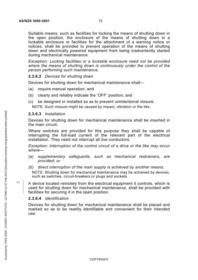
AS/NZS 3000:2007 72
COPYRIGHT
Suitable means, such as facilities for locking the means of shutting down in the open position, the enclosure of the means of shutting down in a lockable enclosure or facilities for the attachment of a warning notice or notices, shall be provided to prevent operation of the means of shutting down and electrically powered equipment from being inadvertently started during mechanical maintenance.
Exception: Locking facilities or a lockable enclosure need not be provided where the means of shutting down is continuously under the control of the person performing such maintenance.
2.3.6.2 Devices for shutting down
Devices for shutting down for mechanical maintenance shall—
(a) require manual operation; and
(b) clearly and reliably indicate the ‘OFF’ position; and
(c) be designed or installed so as to prevent unintentional closure.
NOTE: Such closure might be caused by impact, vibration or the like.
2.3.6.3 Installation
Devices for shutting down for mechanical maintenance shall be inserted in the main circuit.
Where switches are provided for this purpose they shall be capable of interrupting the full-load current of the relevant part of the electrical installation. They need not interrupt all live conductors.
Exception: Interruption of the control circuit of a drive or the like may occur where—
(a) supplementary safeguards, such as mechanical restrainers, are provided; or
(b) direct interruption of the main supply is achieved by another means.
NOTE: Shutting down for mechanical maintenance may be achieved by devices, such as switches, circuit-breakers or plugs and sockets.
A device located remotely from the electrical equipment it controls, which is used for shutting down for mechanical maintenance, shall be provided with facilities for securing it in the open position.
2.3.6.4 Identification
Devices for shutting down for mechanical maintenance shall be placed and marked so as to be readily identifiable and convenient for their intended use.
A1
Acc
esse
d by
TA
FE
NS
W -
SY
DN
EY
INS
TIT
UT
E -
ULT
IMO
on
07 F
eb 2
013
(Doc
umen
t cur
renc
y no
t gua
rant
eed
whe
n pr
inte
d)

73 AS/NZS 3000:2007
COPYRIGHT
2.3.7 Functional (control) switching
2.3.7.1 General
Functional switching may be used where switching of electrical equipment, or part of an electrical installation, is required for operational control only and not for safety reasons.
NOTE: Functional switching devices may be switches, semiconductor (solid-state) devices, or contactors.
A functional switching device shall be provided for each part of a circuit or item of apparatus that may be required to be controlled independently of other parts of the electrical installation or apparatus.
A single functional switching device may control several items of apparatus intended to operate simultaneously.
NOTE: The switching device may form part of the apparatus.
2.3.7.2 Functional switching devices
Disconnectors, fuses or links shall not be used for functional switching.
Functional switching devices shall be suitable for the most onerous of the duties that they might be required to perform.
NOTE: The type of loading, the frequency of operation, and the anticipated number of operations should be taken into account when assessing the most onerous duty. (Systems of duty classification are to be found in the Standards relevant to the electrical equipment concerned, or in the switch manufacturer's information.)
Functional switching devices need not switch all live conductors of a circuit.
Functional switching devices controlling loads having a significantly low power factor, such as motors or fluorescent lighting, shall be subject to an appropriate de-rating factor.
Exception: No de-rating factor need apply where the device has been designed for the purpose, e.g. switches having a utilization Category of AC23A in accordance with AS/NZS 3947.3, used to control circuits of fluorescent lighting are deemed to be designed for the purpose.
2.3.7.3 Identification
Functional switching devices need not be identified to indicate the ‘ON’ or ‘OFF’ position.
Exception: Appliance switches shall be identified to include the ‘OFF’ position, in accordance with AS/NZS 61058.1
2.3.7.4 Control circuits
Control circuits shall be designed, arranged and protected to limit dangers resulting from a fault between the control circuit and other conductive parts liable to cause malfunction, e.g. inadvertent operations of the controlled apparatus.
Acc
esse
d by
TA
FE
NS
W -
SY
DN
EY
INS
TIT
UT
E -
ULT
IMO
on
07 F
eb 2
013
(Doc
umen
t cur
renc
y no
t gua
rant
eed
whe
n pr
inte
d)

AS/NZS 3000:2007 74
COPYRIGHT
2.4 FAULT PROTECTION
2.4.1 General
The following methods of fault protection are recognized in this Standard:
(a) Automatic disconnection of supply, in accordance with Clause 1.5.5.3.
(b) The use of Class II equipment or equivalent insulation, in accordance with Clause 1.5.5.4.
(c) Electrical separation, in accordance with Clauses 1.5.5.5 and 7.4.
The requirements for protection by means of automatic disconnection of supply are set out in Clauses 2.4.2, 2.4.3, 2.5 and 2.6.
2.4.2 Protection by automatic disconnection of supply
Protection by means of automatic disconnection of supply is intended to limit the prospective touch voltage arising between simultaneously accessible conductive parts in the event of a fault between a live part and exposed conductive parts or a protective earthing conductor.
This protection shall be achieved by—
(a) provision of a system of earthing in which exposed conductive parts are connected to a protective earthing conductor, in accordance with Section 5; and
(b) disconnection of the fault by an overcurrent protective device or an RCD.
2.4.3 Types of devices
A device used for protection by automatic disconnection of supply shall not be capable of automatically re-closing. The following types of devices may be employed to provide automatic disconnection of supply:
(a) Enclosed fuse-links complying with the appropriate Standard(s) in the AS 60269 series.
(b) Miniature overcurrent circuit-breakers complying with AS/NZS 60898 or AS/NZS 3111.
(c) Moulded-case circuit-breakers complying with AS 60947.2.
(d) Fixed setting RCDs complying with AS/NZS 3190, AS/NZS 61008.1 or AS/NZS 61009.1.
(e) Other devices, with no automatic reclose function, having characteristics similar to any of the devices listed in Items (a) to (d).
Semi-enclosed rewireable fuses shall not be used.
Exception: Devices with an automatic reclose function of the type that automatically verify the insulation is satisfactory before the device recloses are permitted.
2.4.4 Auto reclose devices
A device may be of the auto reclose type provided that the following conditions are met:
A2
Acc
esse
d by
TA
FE
NS
W -
SY
DN
EY
INS
TIT
UT
E -
ULT
IMO
on
07 F
eb 2
013
(Doc
umen
t cur
renc
y no
t gua
rant
eed
whe
n pr
inte
d)
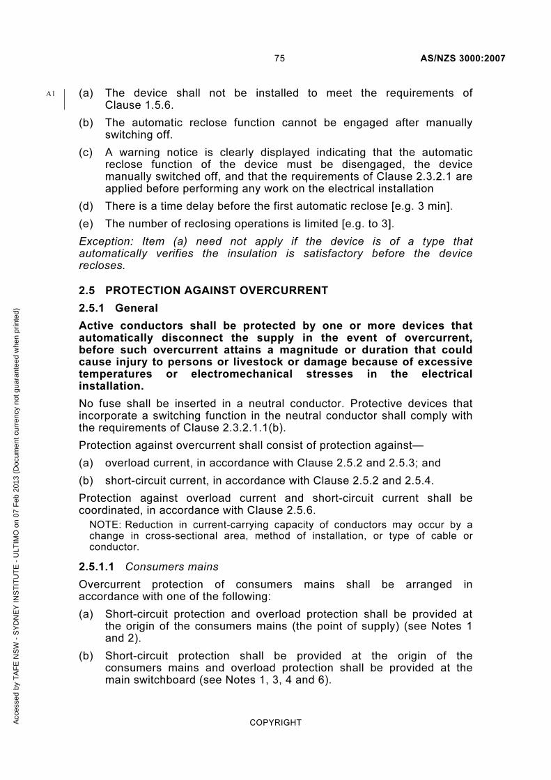
75 AS/NZS 3000:2007
COPYRIGHT
(a) The device shall not be installed to meet the requirements of Clause 1.5.6.
(b) The automatic reclose function cannot be engaged after manually switching off.
(c) A warning notice is clearly displayed indicating that the automatic reclose function of the device must be disengaged, the device manually switched off, and that the requirements of Clause 2.3.2.1 are applied before performing any work on the electrical installation
(d) There is a time delay before the first automatic reclose [e.g. 3 min].
(e) The number of reclosing operations is limited [e.g. to 3].
Exception: Item (a) need not apply if the device is of a type that automatically verifies the insulation is satisfactory before the device recloses.
2.5 PROTECTION AGAINST OVERCURRENT
2.5.1 General
Active conductors shall be protected by one or more devices that automatically disconnect the supply in the event of overcurrent, before such overcurrent attains a magnitude or duration that could cause injury to persons or livestock or damage because of excessive temperatures or electromechanical stresses in the electrical installation.
No fuse shall be inserted in a neutral conductor. Protective devices that incorporate a switching function in the neutral conductor shall comply with the requirements of Clause 2.3.2.1.1(b).
Protection against overcurrent shall consist of protection against—
(a) overload current, in accordance with Clause 2.5.2 and 2.5.3; and
(b) short-circuit current, in accordance with Clause 2.5.2 and 2.5.4.
Protection against overload current and short-circuit current shall be coordinated, in accordance with Clause 2.5.6.
NOTE: Reduction in current-carrying capacity of conductors may occur by a change in cross-sectional area, method of installation, or type of cable or conductor.
2.5.1.1 Consumers mains
Overcurrent protection of consumers mains shall be arranged in accordance with one of the following:
(a) Short-circuit protection and overload protection shall be provided at the origin of the consumers mains (the point of supply) (see Notes 1 and 2).
(b) Short-circuit protection shall be provided at the origin of the consumers mains and overload protection shall be provided at the main switchboard (see Notes 1, 3, 4 and 6).
A1
Acc
esse
d by
TA
FE
NS
W -
SY
DN
EY
INS
TIT
UT
E -
ULT
IMO
on
07 F
eb 2
013
(Doc
umen
t cur
renc
y no
t gua
rant
eed
whe
n pr
inte
d)

AS/NZS 3000:2007 76
COPYRIGHT
(c) Short-circuit protection need not be provided where overload protection is provided at the main switchboard and the consumers mains are constructed and installed in accordance with Clause 3.9.7.1.2 (see Notes 1, 5 and 6).
NOTES:
1 Where consumers mains provide supply to safety services compliance with Clause 7.2.2. is also required.
2 An electricity distributor's low voltage service protective device may provide overload and short-circuit protection for consumers mains and may satisfy Clause 2.5.5.3 under certain conditions.
3 An electricity distributor's low voltage service protective device, may provide short-circuit protection only for consumers mains under certain conditions.
4 Where no low voltage service protection device is installed on the secondary side of an electricity distributor’s transformer, an appropriately sized high voltage fuse or circuit-breaker may provide short-circuit protection for the consumers mains under certain conditions.
5 The arrangement of Subclause (c) is regarded as unprotected consumers mains.
6 Consumers mains supplying one or more circuits that are individually protected against overload are deemed to be provided with overload protection where the sum of the current ratings of the individual circuit-breakers so supplied does not exceed the current-carrying capacity of the consumers mains.
2.5.1.2 Submains and final subcircuits
An overcurrent protective device or devices ensuring protection against overload current and short-circuit current shall be placed at the origin of every circuit and at each point where a reduction occurs in the current-carrying capacity of the conductors.
NOTE: The general arrangement of protective devices is shown at Figure 2.1.
Exceptions:
1 Overcurrent protective devices shall not be provided on circuits where the unexpected interruption of the supply could cause a greater danger than overcurrent (see Clause 2.5.1.3).
2 Overcurrent protective devices may be located at an alternative position in accordance with Clauses 2.5.3.3 and 2.5.4.3.
3 Overcurrent protective devices may be omitted in accordance with Clauses 2.5.3.4 and 2.5.4.4.
A1
Acc
esse
d by
TA
FE
NS
W -
SY
DN
EY
INS
TIT
UT
E -
ULT
IMO
on
07 F
eb 2
013
(Doc
umen
t cur
renc
y no
t gua
rant
eed
whe
n pr
inte
d)

77 AS/NZS 3000:2007
COPYRIGHT
2.5.1.3 Omission of protective device for safety reasons
Devices for protection against overcurrent shall not be provided for circuits where unexpected opening of the circuit could cause a danger greater than overcurrent.
NOTES:
1 Examples of such circuits are certain safety system supplies, lifting magnets, exciter circuits of machines and the secondary circuits of current transformers. In such cases the provision of an overload alarm is strongly recommended.
2 The omission of protective devices is shown at Figure 2.2.
2.5.2 Devices for protection against both overload and short-circuit currents
Protective devices providing protection against both overload and short-circuit current, shall be capable of breaking any overcurrent up to and including the prospective short-circuit current at the point where the device is installed.
Exception: A protective device having a breaking capacity below the value of the prospective short-circuit current may be used in conjunction with another device in accordance with Clause 2.5.4.3.
The device shall comply with the requirements of Clauses 2.5.3 and 2.5.4.
Protective devices may be one of the following:
(a) Circuit-breakers incorporating short-circuit and overload releases.
(b) Fuse-combination units (CFS units)
(c) Fuses having enclosed fuse-links (HRC fuses).
(d) Circuit-breakers in conjunction with fuses.
Semi-enclosed rewireable fuses shall not be used.
NOTES:
1 General-purpose fuses (Type gG) and overcurrent circuit-breakers normally combine overload and short-circuit protection in the one device.
2 A fuse comprises all the parts that form the complete protective device.
3 Circuit-breakers that meet the requirements for the type of protection required and replace a fuse-carrier by insertion in a fuse base are acceptable. However, because of interchangeability with semi-enclosed rewireable fuse-carriers, such circuit-breakers should be rated at not more than 80% of the current-carrying capacity of the protected conductor.
4 Screw-type fuses of the enclosed type that meet the requirements of AS 60269.3.1 are acceptable.
Acc
esse
d by
TA
FE
NS
W -
SY
DN
EY
INS
TIT
UT
E -
ULT
IMO
on
07 F
eb 2
013
(Doc
umen
t cur
renc
y no
t gua
rant
eed
whe
n pr
inte
d)

AS/NZS 3000:2007 78
COPYRIGHT
2.5.3 Protection against overload current
2.5.3.1 Coordination between conductors and protective devices
The operating characteristics of a device protecting a conductor against overload shall satisfy the following two conditions:
IB ≤ IN ≤ IZ . . . 2.1
I2 ≤ 1.45 × IZ . . . 2.2
where
IB = the current for which the circuit is designed, e.g. maximum demand
IN = the nominal current of the protective device
IZ = the continuous current-carrying capacity of the conductor (see AS/NZS 3008.1 series)
I2 = the current ensuring effective operation of the protective device and may be taken as equal to either—
(a) the operating current in conventional time for circuit-breakers (1.45 IN); or
(b) the fusing current in conventional time for fuses (1.6 IN for fuses in accordance with the AS/NZS 60269 series).
To satisfy equation 2.2, the nominal current IN of a fuse should not exceed 90% of IZ (1.45/1.6 = 0.9), therefore:
For circuit-breakers Equation 2.1 applies
For HRC fuses IB ≤ IN ≤ 0.9 IZ . . . 2.3
NOTES:
1 For adjustable devices, the nominal current IN is the current setting selected.
2 Protection in accordance with this Clause will not ensure complete protection in certain cases, e.g. against sustained overcurrent less than IZ nor will it necessarily result in an economical solution. Therefore it is assumed that the circuit is so designed that small overloads of long duration will not frequently occur. Such overloads can cause premature ageing of the insulation.
3 For further information see also Paragraph B3.2.1, Appendix B.
2.5.3.2 Position of overload protective device
In accordance with Clause 2.5.1.2 a device providing protection against overload shall be installed at the origin of every circuit and at each point where a reduction occurs in the current-carrying capacity of the conductors.
Exception: In accordance with the conditions set out in Clauses 2.5.3.3 and 2.5.3.4, an overload protective device may be located in another position or may be omitted.
A1
Acc
esse
d by
TA
FE
NS
W -
SY
DN
EY
INS
TIT
UT
E -
ULT
IMO
on
07 F
eb 2
013
(Doc
umen
t cur
renc
y no
t gua
rant
eed
whe
n pr
inte
d)

79 AS/NZS 3000:2007
COPYRIGHT
2.5.3.3 Alternative position of overload protective device
A device providing protection of a conductor against overload current may be placed at a point other than the origin of the circuit provided that—
(a) the conductor has no branch circuits or socket-outlets connected between the origin of the conductor and the overload protective device; or
(b) the conductor supplies one or more circuits that are individually protected against overload, such as within a switchboard or busway, and the sum of the current ratings of the circuit protective devices supplied by the conductor does not exceed the current-carrying capacity of the conductor.
NOTE: Examples of alternative position of overload protective devices are shown in Figures 2.3 and 2.4.
2.5.3.4 Omission of overload protective device
Devices for protection against overload current may be omitted under the following conditions:
(a) Where unexpected opening of the circuit could cause a danger greater than overload, devices for protection against overload current shall be omitted, in accordance with Clause 2.5.1.3.
(b) Provided that the conductor is not situated in a location presenting a fire risk, or a risk of explosion, or where requirements for special installations and locations specify different conditions, and the conductor—
(i) is situated on the load side of a change in current-carrying capacity that is effectively protected against overload by a protective device placed on the supply side of the origin of the conductor; or
(ii) supplies electrical equipment that is not capable of causing an overload current and the conductor has no branch circuits or socket-outlets connected between the origin of the conductor and the electrical equipment; or
(iii) is provided for installations of telecommunications, control, signalling and the like.
NOTES:
1 A heating appliance is an example of equipment not capable of causing an overload current.
2 Examples of omission of overload protection are shown at Figures 2.5 and 2.6.
2.5.4 Protection against short-circuit current
NOTE: The requirements of this Clause take into account only cases of short-circuit anticipated between conductors belonging to the same circuit.
Acc
esse
d by
TA
FE
NS
W -
SY
DN
EY
INS
TIT
UT
E -
ULT
IMO
on
07 F
eb 2
013
(Doc
umen
t cur
renc
y no
t gua
rant
eed
whe
n pr
inte
d)
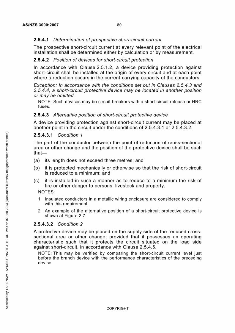
AS/NZS 3000:2007 80
COPYRIGHT
2.5.4.1 Determination of prospective short-circuit current
The prospective short-circuit current at every relevant point of the electrical installation shall be determined either by calculation or by measurement.
2.5.4.2 Position of devices for short-circuit protection
In accordance with Clause 2.5.1.2, a device providing protection against short-circuit shall be installed at the origin of every circuit and at each point where a reduction occurs in the current-carrying capacity of the conductors
Exception: In accordance with the conditions set out in Clauses 2.5.4.3 and 2.5.4.4, a short-circuit protective device may be located in another position or may be omitted.
NOTE: Such devices may be circuit-breakers with a short-circuit release or HRC fuses.
2.5.4.3 Alternative position of short-circuit protective device
A device providing protection against short-circuit current may be placed at another point in the circuit under the conditions of 2.5.4.3.1 or 2.5.4.3.2.
2.5.4.3.1 Condition 1
The part of the conductor between the point of reduction of cross-sectional area or other change and the position of the protective device shall be such that—
(a) its length does not exceed three metres; and
(b) it is protected mechanically or otherwise so that the risk of short-circuit is reduced to a minimum; and
(c) it is installed in such a manner as to reduce to a minimum the risk of fire or other danger to persons, livestock and property.
NOTES:
1 Insulated conductors in a metallic wiring enclosure are considered to comply with this requirement.
2 An example of the alternative position of a short-circuit protective device is shown at Figure 2.7.
2.5.4.3.2 Condition 2
A protective device may be placed on the supply side of the reduced cross-sectional area or other change, provided that it possesses an operating characteristic such that it protects the circuit situated on the load side against short-circuit, in accordance with Clause 2.5.4.5.
NOTE: This may be verified by comparing the short-circuit current level just before the branch device with the performance characteristics of the preceding device.
Acc
esse
d by
TA
FE
NS
W -
SY
DN
EY
INS
TIT
UT
E -
ULT
IMO
on
07 F
eb 2
013
(Doc
umen
t cur
renc
y no
t gua
rant
eed
whe
n pr
inte
d)

81 AS/NZS 3000:2007
COPYRIGHT
2.5.4.4 Omission of devices for short-circuit protection
Devices for protection against short-circuit current may be omitted under the following conditions.
Where unexpected opening of the circuit could cause a danger greater than short-circuit, devices for protection against short-circuit shall be omitted, in accordance with Clause 2.5.1.3.
Consumers mains constructed in accordance with Clause 3.9.7.1 need not be provided with short-circuit protection.
Conductors connecting generators, transformers, rectifiers or batteries to their associated switchboards need not be provided with short-circuit protection provided that—
(a) the wiring is carried out in such a way as to reduce the risk of a short-circuit to a minimum; and
(b) the wiring is not placed close to flammable material; and
(c) the short-circuit protective devices for the remainder of the circuit are placed on the associated switchboard.
NOTE: Examples of the omission of devices for short-circuit protection are shown at Figures 2.2 and 2.8.
2.5.4.5 Characteristics of short-circuit protective devices
Short-circuit protective devices shall meet the following conditions:
(a) The breaking capacity shall be not less than the prospective short-circuit current at the point where the devices are installed.
Exception: A device having a lower breaking capacity is permitted if another protective device having the necessary breaking capacity is installed on the supply side. In this case, the characteristics of the devices shall be coordinated so that the energy let through by these two devices does not exceed that which can be withstood without damage by the device on the load side and the conductors protected by those devices.
NOTE: In certain cases, other characteristics may need to be taken into account, such as dynamic stresses and arcing energy, for the device on the load side. Details of the characteristics needing coordination should be obtained from the manufacturers of the devices concerned.
(b) All currents caused by a short-circuit occurring at any point of a circuit shall be interrupted before the temperature of the conductors reaches the permissible limit.
Acc
esse
d by
TA
FE
NS
W -
SY
DN
EY
INS
TIT
UT
E -
ULT
IMO
on
07 F
eb 2
013
(Doc
umen
t cur
renc
y no
t gua
rant
eed
whe
n pr
inte
d)

AS/NZS 3000:2007 82
COPYRIGHT
For short-circuits of duration up to 5 s, the time in which a given short-circuit current will raise the conductors from the highest permissible temperature in normal duty to the limit temperature may, as an approximation, be calculated from the following equation:
2
22
I
SKt =
. . . 2.4
where
t = duration in seconds
K = factor dependent on the material of the conductor, the insulation and the initial and the final temperatures
S = cross-sectional area of the conductor in mm2
I = effective short-circuit current in amps (r.m.s)
NOTES:
1 Values of K for conductors in various conditions of service are given in the AS/NZS 3008.1 series, e.g. for copper conductors with PVC insulation, K = 111 for 40°C ambient.
2 For very short duration (< 0.1 s) where asymmetry of the current is of importance and for current limiting devices, K2S2
should be greater than the value of the let-through energy (I2t) stated by the manufacturer of the protective device.
3 The nominal current of the short-circuit protective device may be greater than the current-carrying capacity of the cable.
4 Other methods of calculation are permissible.
Acc
esse
d by
TA
FE
NS
W -
SY
DN
EY
INS
TIT
UT
E -
ULT
IMO
on
07 F
eb 2
013
(Doc
umen
t cur
renc
y no
t gua
rant
eed
whe
n pr
inte
d)

83 AS/NZS 3000:2007
COPYRIGHT
Clauses 2.5.3.2 and 2.5.4.2Over load and shor t-c i rcu i t
protect ion at or ig inof each c i rcu i t
PD = Protect ive dev icein accordance wi th
Clause 2.5.2
Over load andshor t-c i rcu i t PD
Over load andshor t-c i rcu i t PD
Over load andshor t-c i rcu i t PD
FIGURE 2.1 CLAUSES 2.5.1, 2.5.3.2 AND 2.5.4.2 GENERAL PROTECTION ARRANGEMENT
Acc
esse
d by
TA
FE
NS
W -
SY
DN
EY
INS
TIT
UT
E -
ULT
IMO
on
07 F
eb 2
013
(Doc
umen
t cur
renc
y no
t gua
rant
eed
whe
n pr
inte
d)

AS/NZS 3000:2007 84
COPYRIGHT
Clause 2.5.1.3Over load and shor t-c i rcu i t
protect ion not permit ted forc i rcu i ts where loss of supply could
cause greater danger thanovercurrent
A
B
Unexpected loss of supplycannot be to leratede.g. L i f t ing magnets,
exc i ter c i rcu i t,CT secondar y c i rcu i t
FIGURE 2.2 CLAUSE 2.5.1.3—OMISSION OF OVERCURRENT PROTECTION FOR SAFETY REASONS
Acc
esse
d by
TA
FE
NS
W -
SY
DN
EY
INS
TIT
UT
E -
ULT
IMO
on
07 F
eb 2
013
(Doc
umen
t cur
renc
y no
t gua
rant
eed
whe
n pr
inte
d)

85 AS/NZS 3000:2007
COPYRIGHT
No branch c i rcu i tsor socket-out letsbetween A and B(Clause 2.5.3.3 )
Shor t-c i rcu i t
PD
OverloadPD Over
loadPD
A
B
A
B
FIGURE 2.3 CLAUSE 2.5.3.3 (a)—ALTERNATIVE POSITION OF OVERLOAD PROTECTIVE DEVICE
Acc
esse
d by
TA
FE
NS
W -
SY
DN
EY
INS
TIT
UT
E -
ULT
IMO
on
07 F
eb 2
013
(Doc
umen
t cur
renc
y no
t gua
rant
eed
whe
n pr
inte
d)

AS/NZS 3000:2007 86
COPYRIGHT
No branch c i rcu i tsor socket-out lets
connectedto conductor AB
Sum of over loadPDs not exceeding
capaci t yof conductor AB
(Clause 2.5.3.3 (b ) )
A
B
Shor t-c i rcu i t
PD
OverloadPD
OverloadPD
OverloadPD
OverloadPD
FIGURE 2.4 CLAUSE 2.5.3.3(b)—ALTERNATIVE POSITION OF OVERLOAD PROTECTIVE DEVICE
No r isk of f i re or explos ionNo specia l requi rements
Upstream dev ice protectsdownstream conductors
Clause 2.5.3.4 (b ) ( i )
OverloadPD
FIGURE 2.5 CLAUSE 2.5.3.4(b)(i)—OMISSION OF OVERLOAD PROTECTION—CONDUCTOR ON LOAD SIDE OF A CHANGE IN
CURRENT-CARRYING CAPACITY
Acc
esse
d by
TA
FE
NS
W -
SY
DN
EY
INS
TIT
UT
E -
ULT
IMO
on
07 F
eb 2
013
(Doc
umen
t cur
renc
y no
t gua
rant
eed
whe
n pr
inte
d)

87 AS/NZS 3000:2007
COPYRIGHT
Clause 2.5.3.4 (b ) ( i i ) ,conductor AB has-
• shor t-c i rcu i t protect ion• no r isk of f i re or explos ion• no specia l requi rements• no branch c i rcu i ts or socket-out lets
A
B
Equipment incapableof caus ing over load
e.g. water heater
Shor t-c i rcu i t
PD
FIGURE 2.6 CLAUSE 2.5.3.4(b)(ii)—OMISSION OF OVERLOAD PROTECTION—FIXED LOAD NOT CAPABLE OF CAUSING AN
OVERLOAD CURRENT
Acc
esse
d by
TA
FE
NS
W -
SY
DN
EY
INS
TIT
UT
E -
ULT
IMO
on
07 F
eb 2
013
(Doc
umen
t cur
renc
y no
t gua
rant
eed
whe
n pr
inte
d)

AS/NZS 3000:2007 88
COPYRIGHT
Clause 2.5.4.3.1Conductor AB sha l l -
• not exceed 3 m in length• be protected mechanica l ly to min imize r isk of shor t-c i rcu i t• be insta l led to min imize r isk of f i re
To load, v ia over load PDin accordance wi th
Clause 2.5.3
Shor t-c i rcu i t
PD
A
B
FIGURE 2.7 CLAUSE 2.5.4.3—ALTERNATIVE POSITION OF SHORT-CIRCUIT PROTECTIVE DEVICE
Clause 2.5.4.4Conductor AB -
• insta l led to min imize r isk of shor t-c i rcu i t• not near f lammable mater ia ls
Switchboard conta in ingoutgoing c i rcu i t protect ion
Generator, t ransformer,rect i f ie r or bat ter ies
A
B
FIGURE 2.8 CLAUSE 2.5.4.4—OMISSION OF SHORT-CIRCUIT PROTECTION
Acc
esse
d by
TA
FE
NS
W -
SY
DN
EY
INS
TIT
UT
E -
ULT
IMO
on
07 F
eb 2
013
(Doc
umen
t cur
renc
y no
t gua
rant
eed
whe
n pr
inte
d)

89 AS/NZS 3000:2007
COPYRIGHT
Su
bm
ain
A-H
Ove
rlo
ad
PD
(s
ee
Cla
use
2.5
.3.2
) a
t A
Sh
ort
cir
cu
it P
D
(se
e C
lau
se 2
.5.4
.2)
at
A
B
C
Fin
al
sub
cir
cu
it B
-C
Ove
rlo
ad
PD
(s
ee
Cla
use
2.5
.3.2
) a
t B
Sh
ort
cir
cu
it P
D
(se
e C
lau
se 2
.5.4
.2)
at
B
H I
A
D
E3 m
GF
Fin
al
sub
cir
cu
it D
-EN
o p
rote
cti
on
at
D
Ove
rlo
ad
PD
(s
ee
Cla
use
2.5
.3.3
(a))
at
E
Sh
ort
cir
cu
it P
D
(se
e C
lau
se 2
.5.4
.2)
at
EIf
le
ng
th
3 m
, m
ec
ha
nic
ally
p
rote
cte
d,
no
t n
ea
r fl
am
ma
ble
ma
teri
al
Fin
al
su
bc
irc
uit
F-G
No
pro
tec
tio
n a
t F
Ove
rlo
ad
PD
s (s
ee
Cla
use
2.5
.3.3
(b))
d
ow
nst
rea
m o
f G
If t
he
su
m o
f o
verl
oa
d
sett
ing
s
ca
ble
ra
tin
g,
no
b
ran
ch
cir
cu
its,
no
so
cke
t o
utl
ets
Sh
ort
cir
cu
it P
D a
t A
(se
e
Cla
use
2.5
.4.3
)If
pro
tec
tio
n g
ive
n t
o F
G
Fin
al
sub
cir
cu
it H
-I
Ove
rlo
ad
PD
(s
ee
Cla
use
2.5
.3.3
(a))
at
IIf
no
bra
nc
h c
irc
uit
s, n
o
soc
ket
ou
tle
ts
Sh
ort
cir
cu
it P
D a
t H
(se
e
Cla
use
2.5
.4.2
)
PD
PD
PD
PD
PD
PD
PD
PD
PD
Ove
rcu
rre
nt
pro
tec
tio
n a
t o
rig
in
Ove
rcu
rre
nt
pro
tec
tio
n a
t o
rig
in
Alt
ern
ati
ve p
osi
tio
n o
f O
verl
oa
d p
rote
cti
on
an
d
Alt
ern
ati
ve p
osi
tio
n o
f S
ho
rt c
irc
uit
pro
tec
tio
n
Alt
ern
ati
ve p
osi
tio
n o
f O
verl
oa
d p
rote
cti
on
an
d
Alt
ern
ati
ve p
osi
tio
n o
f S
ho
rt c
irc
uit
pro
tec
tio
n
Alt
ern
ati
ve p
osi
tio
n o
f O
verl
oa
d p
rote
cti
on
an
d
Alt
ern
ati
ve p
osi
tio
n o
f S
ho
rt c
irc
uit
pro
tec
tio
n
FIG
UR
E
2.9
E
XA
MP
LE
LO
CA
TIO
N O
F P
RO
TE
CT
IVE
DE
VIC
E O
PT
ION
S F
OR
RIS
ING
MA
INS
OR
SU
BM
AIN
DIS
TR
IBU
TIO
N
Acc
esse
d by
TA
FE
NS
W -
SY
DN
EY
INS
TIT
UT
E -
ULT
IMO
on
07 F
eb 2
013
(Doc
umen
t cur
renc
y no
t gua
rant
eed
whe
n pr
inte
d)

AS/NZS 3000:2007 90
COPYRIGHT
2.5.5 Protection against switchboard internal arcing fault currents
2.5.5.1 General
Protection against arcing fault currents while the equipment is in service, or is undergoing maintenance, shall be provided for heavy current switchboards.
NOTE: Heavy current circuits are regarded as those where the nominal supply current to the switchboard is 800 A or more per phase.
The supply conductors up to the line side of the protective device(s) within the switchboard shall be provided with means to reduce the probability of initiation of arcing faults by insulation or by separation.
NOTES:
1 Refer to AS/NZS 3439.1 for switchboard requirements and AS/NZS 3439.2 for busways.
2 See also Clause 2.5.1.1 regarding requirements for consumers mains.
3 Separation of live supply conductors from each other by insulation or barriers in accordance with this Clause 2.5.5.1 is not a requirement of separation, e.g. an IP2X enclosure with bare busbars is acceptable.
In addition, the switchboard shall comply with one of the following:
(a) Clause 2.5.5.2 to reduce the probability of initiation of a switchboard internal arcing fault.
(b) Clause 2.5.5.3. to limit as far as practicable the harmful effects of an internal arcing fault.
(c) One of the forms of internal separation required by Clause 2.5.5.2 together with Clause 2.5.5.3 to reduce the probability of initiation and limit, as far as practicable, the harmful effects of an internal arcing fault.
2.5.5.2 Reduction of the probability of the initiation of a switchboard internal arcing fault
Heavy current switchboards shall be provided with internal separation in accordance with AS/NZS 3439.1 for—
(a) busbars from functional units; and
(b) functional units from one another; and
(c) terminals provided for external conductors from the busbar; and
(d) a safety service circuit section of the switchboard, if any, from the general installation circuits section, in accordance with Clause 7.2.8.
NOTES:
1 Separation in accordance with AS/NZS 3439.1 may be achieved by the insulation of busbars, the use of barriers or by insulated housings, i.e. by the use of a Form 3b, Form 3bi, Form 3bh, Form 3bih, Form 4a, Form 4ah, Form 4aih, or Form 4b, Form 4bi, Form 4bh, Form 4bih constructed switchboard.
A2
Acc
esse
d by
TA
FE
NS
W -
SY
DN
EY
INS
TIT
UT
E -
ULT
IMO
on
07 F
eb 2
013
(Doc
umen
t cur
renc
y no
t gua
rant
eed
whe
n pr
inte
d)

91 AS/NZS 3000:2007
COPYRIGHT
2 The required degree of protection, IP2X or IP1XB, is to prevent the entry of objects and contact with live parts by a person’s finger. To prevent the entry of tools or wires the degree of protection may be increased, i.e. small tools IP3X or IP2XC (2.5 mm diameter) and wires IP4X or IP3XD (1 mm diameter).
3 Arc fault containment is not required and is considered to be an enhancement of internal separation. Switchboard arc fault containment is designed to prevent the arc or products of the arc affecting other parts of the switchboard . Arc fault containment is achieved by the arrangement of the busbars and functional units of the switchboard in vented compartments and relies, for its effectiveness, on compartment access doors being closed during a fault. It is not designed to prevent the initiation of a fault during maintenance and is also not designed to provide switching operator or maintenance personnel protection if any covers are not properly fixed in place.
2.5.5.3 Limitation of the harmful effects of a switchboard internal arcing fault
Protective devices shall be provided to limit, as far as practicable, the harmful effects of a switchboard internal arcing fault by automatic disconnection.
The arcing fault current between phases, or between phase and earth, is deemed to be in the range of 30% to 60% of the prospective short-circuit current.
Protection shall be initiated, i.e. pick up at a current less than 30% of the three-phase prospective fault level.
To minimize damage to the switchboard, the interrupting time shall not exceed the value obtained from the following equation.
The general damage limit is given by the following:
Clearing time 5.1
f
re
l
lkt
×=
where:
t = clearing time in seconds
lf = 30% of the prospective fault current
lr = current rating of the switchboard
ke = 250 constant, based on acceptable volume damage
Example
The maximum arcing fault clearing time at a customer’s 800 A-rated main switchboard with a prospective fault current at the switchboard of 16.67 kA.
Therefore, If = 30% of 16.67 kA = 5 kA.
s0.575000
800250
1.5=×
=t
i.e. The protective device settings must be set to clear an arcing fault of 5 kA in less than 0.57 s.
Acc
esse
d by
TA
FE
NS
W -
SY
DN
EY
INS
TIT
UT
E -
ULT
IMO
on
07 F
eb 2
013
(Doc
umen
t cur
renc
y no
t gua
rant
eed
whe
n pr
inte
d)

AS/NZS 3000:2007 92
COPYRIGHT
Overcurrent protective devices should be set to as low an initiation current as possible while still maintaining the correct function of the installation, e.g. set higher than motor-starting currents.
Earth fault protective devices shall have a maximum setting of 1200 A.
The settings of protective devices shall be verified by inspection (see Clause 8.2.2 (c) (ii)).
NOTE: The electricity distributor should be consulted for discrimination requirements between installation protective devices and the electricity distributor’s service protective devices. The curves and settings of service protective devices will be required.
Where arc detectors are used, immunity to extraneous light sources that may cause operation of the protection is necessary. Arc detectors do not obviate requirements for discrimination.
2.5.6 Coordination of overload and short-circuit protective devices
2.5.6.1 Protection afforded by one device
An overload protective device that complies with Clause 2.5.3 and has a breaking capacity not less than the value of the prospective short-circuit current at its point of installation may be deemed to protect the conductor on the load side of that point against short-circuit currents and overload currents.
NOTE: This consideration may not be valid for short-circuit currents lower than the prospective value, or for certain types of circuit-breakers, especially non-current-limiting types. Its validity should be checked, in accordance with the requirements of Clause 2.5.4.2.
2.5.6.2 Protection afforded by separate devices
The requirements of Clauses 2.5.3 and 2.5.4 apply respectively to the overload protective device and to the short-circuit protective device.
The characteristics of the devices shall be coordinated so that the energy let through by the short-circuit protective device does not exceed that which can be withstood without damage by the overload protective device.
The selection of protective devices shall be verified by inspection (see Clause 8.2.2 (c) (ii)).
2.5.7 Reliability of supply
2.5.7.1 General
The electrical installation shall be designed to provide a reliable supply by dividing the electrical installation into appropriate circuits and selecting protective devices with appropriate discrimination so that in the event of a fault occurring, the loss of supply resulting from operation of a protective device is minimized.
The selection and setting of protective devices shall be verified by inspection (see Clause 8.2.2 (c) (ii)).
Acc
esse
d by
TA
FE
NS
W -
SY
DN
EY
INS
TIT
UT
E -
ULT
IMO
on
07 F
eb 2
013
(Doc
umen
t cur
renc
y no
t gua
rant
eed
whe
n pr
inte
d)

93 AS/NZS 3000:2007
COPYRIGHT
2.5.7.2 Coordination of protective devices
2.5.7.2.1 General
Coordination of various protective devices requires consideration of both discrimination and backup (cascading) protection.
Discrimination between protective devices depends on coordination between the operating characteristics of two or more protective devices such that a downstream device with a time/current curve below that of upstream protective device(s) shall operate for a given fault current while the other protective device(s) shall not operate.
Figure 2.10 provides a generic overview of discrimination between protective devices.
Over load andshor t-c i rcu i t PD 1
Over load andshor t-c i rcu i t PD 3
Over load andshor t-c i rcu i t PD 2
FIGURE 2.10 DISCRIMINATION BETWEEN PROTECTIVE DEVICES—GENERAL
NOTES:
1 Discrimination is achieved when PD 1 remains intact while PD 2 clears a fault on the load side. Thus supply is maintained to PD 3 and the remainder of the electrical installation.
2 For examples and detailed requirements, see Figures 2.11 to 2.14.
Acc
esse
d by
TA
FE
NS
W -
SY
DN
EY
INS
TIT
UT
E -
ULT
IMO
on
07 F
eb 2
013
(Doc
umen
t cur
renc
y no
t gua
rant
eed
whe
n pr
inte
d)

AS/NZS 3000:2007 94
COPYRIGHT
2.5.7.2.2 Safety service circuit discrimination
Protective devices shall be selected such that, in accordance with Clause 7.2.2.2—
(a) a fault on one safety service circuit will not result in loss of supply to other safety service circuits; or
(b) a fault on the general electrical installation will not result in loss of supply to safety services.
NOTES:
1 This discrimination is intended to apply only up to the level of an arcing fault, which is deemed to have a maximum value of 60% of the prospective short-circuit current.
2 Examples of protective devices and the arcing fault current are shown in Figures 2.11 to 2.14.
2.5.7.2.3 General supply circuit discrimination
In accordance with Clause 2.5.7.1, to minimize loss of supply, discrimination shall be arranged between protective devices for outgoing circuits and the upstream protective device.
Downstream devices shall be selected to discriminate with upstream devices, using time–current curves, in accordance with the following:
(a) Circuit-breakers Two circuit-breakers, connected such that C2 is the downstream device and C1 the upstream device, shall be selected as follows:
(i) For ratings of C2 greater than or equal to 800 A, discrimination shall be provided between overload curves and up to the instantaneous setting of C1.
(ii) For ratings of C2 greater than or equal to 250 A and less than 800 A, discrimination shall be provided between overload curves and is recommended up to the instantaneous setting of C1.
Discrimination is deemed to be achieved if—
(A) the overload setting of C1 ≥1.6 × C2, e.g. 1000 A with 630 A; and
(B) the instantaneous setting of C1 ≥1.6 × C2, e.g. C1=5 × 1000 A with C2=5 × 630 A.
(iii) For ratings of C2 less than 250 A, discrimination should be provided between overload curves and is recommended up to the instantaneous setting of C1.
Discrimination on overload and instantaneous operation may be deemed to be provided when C1 ≥ 2 × C2, e.g. C1 curve 63 A with C2 curve 32 A (see Figures 2.11 and 2.12.)
(b) Fuses Two fuses connected such that F2 is the downstream device and F1 the upstream device shall be selected such that the characteristics of the devices provide discrimination between the time-current curves for all ratings of F2 (see Figure 2.13).
Acc
esse
d by
TA
FE
NS
W -
SY
DN
EY
INS
TIT
UT
E -
ULT
IMO
on
07 F
eb 2
013
(Doc
umen
t cur
renc
y no
t gua
rant
eed
whe
n pr
inte
d)

95 AS/NZS 3000:2007
COPYRIGHT
Discrimination between HRC fuses is deemed to be achieved—
(i) for times >0.01 s when F1 ≥ 1.6 × F2., e.g. 16 A with 10 A
(ii) for times < 0.01 s when F1 ≥ 2 × F2., e.g. 20 A with 10 A (based on the total I 2 t of F2 ≤ pre-arcing I2 t of F1).
(c) Fuse and circuit-breaker A fuse and a circuit-breaker connected such that C2 is the downstream device and F1 the upstream device shall be selected such that the characteristics of the devices provide discrimination between the overload curve and the instantaneous setting of C2 and the time-current curve of F1 for all ratings of C2 (see Figure 2.14).
NOTES:
1 A coordination study is necessary to determine the correct selection and setting of protective devices for discrimination. This study requires the curves and settings of protective devices together with the prospective short-circuit currents. The arcing fault current is to be determined for safety circuits. If devices are to be installed above their rated short-circuit capacity the backup protection requirement is to be determined from manufacturer’s data.
2 For currents higher than the instantaneous setting of upstream circuit-breakers, or higher than the limit of fuse time–current curves at 0.01 s, manufacturer’s data is required to determine discrimination. Discrimination by the use of short-time delay is acceptable.
3 Discrimination, when backup protection of a circuit-breaker is applied, is limited and the value must be obtained from the manufacturers. For fuse backup, discrimination is generally limited to the limit of fuse time–current curve. For circuit-breaker backup, discrimination depends on the circuit-breaker design and the limit must be supplied by the manufacturer.
4 Refer to Clause 2.5.5 for other requirements for heavy current main switchboards.
5 The electricity distributor should be consulted for discrimination requirements between installation protective devices and the electricity distributor’s service protective devices. The curves and settings of service protective devices will be required.
6 The following terms are used in Figures 2.11 to 2.14:
IPSC = prospective short-circuit current (see Clause 1.4.39).
Iarc = deemed maximum arcing fault current (= 60%IPSC).
Ii = instantaneous setting.
ISD = short delay setting.
0.01 s = the limit of fuse time–current.
Acc
esse
d by
TA
FE
NS
W -
SY
DN
EY
INS
TIT
UT
E -
ULT
IMO
on
07 F
eb 2
013
(Doc
umen
t cur
renc
y no
t gua
rant
eed
whe
n pr
inte
d)

AS/NZS 3000:2007 96
COPYRIGHT
CURRENT
0.01 S
TIM
E
C1
C2
I i or ISD
Iarc IPSC
C1
C2
Over load protect iont ime-current cur ves
Instantaneousprotect ion set t ings
For d iscr iminat ion C1 instantaneous set t ing,consul t manufacturer
Shor t-c i rcu i t zone
FIGURE 2.11 CIRCUIT-BREAKER CURVES—GENERAL EXPLANATION, SETTINGS AND ZONES
CURRENT
0.01 S
TIM
E
I a rc IPSC
C1
C2
C2 250 A up to 800 ADiscr iminat ion is :• requi red between over load cur ves ; and • recommended up to the instantaneous set t ing of C1
C1
C2
C2 800 ADiscr iminat ion is requi red :• between over load cur ves ; and• up to the instantaneous set t ing of C1
C2 250 A Discr iminat ion is requi redbetween over load cur ves
Safety c i rcu i tsFor a l l rat ings, d iscr iminat ionis requi red between C2 and C1up to the arc ing fau l t leve l
FIGURE 2.12 CIRCUIT-BREAKER CURVES WITH DISCRIMINATION REQUIREMENTS
Acc
esse
d by
TA
FE
NS
W -
SY
DN
EY
INS
TIT
UT
E -
ULT
IMO
on
07 F
eb 2
013
(Doc
umen
t cur
renc
y no
t gua
rant
eed
whe
n pr
inte
d)

97 AS/NZS 3000:2007
COPYRIGHT
CURRENT
Shor t c i rcu i t zone0.01 S
TIM
E
I a rc IPSC
F2F1
F2
F1
T ime-currentcur ves
Safety c i rcu i tsFor a l l rat ings, d iscr iminat ionis requi red between F2 and F1up to the arc ing fau l t leve l
For d iscr iminat ion 0.01 secconsul t manufacturers dataF2 I2 t tota l F1 I2 t pre-arc ing
FIGURE 2.13 FUSE CURVES WITH DISCRIMINATION REQUIREMENTS
CURRENT
0.01 S
TIM
E
I a rc IPSC
F1F1
C2
Fuse t ime-current cur ve
For d iscr iminat ion fuse t ime-current cur veconsul t manufacturer
C2
Over load protect iont ime-current cur ve
Instantaneousprotect ion set t ing
I i or ISD
Shor t c i rcu i t zone
Safety c i rcu i tsFor a l l rat ings,d iscr iminat ion isrequi red betweenC2 and F1 up to thearc ing fau l t leve l
FIGURE 2.14 FUSE AND CIRCUIT-BREAKER CURVES WITH DISCRIMINATION REQUIREMENTS
Acc
esse
d by
TA
FE
NS
W -
SY
DN
EY
INS
TIT
UT
E -
ULT
IMO
on
07 F
eb 2
013
(Doc
umen
t cur
renc
y no
t gua
rant
eed
whe
n pr
inte
d)

AS/NZS 3000:2007 98
COPYRIGHT
2.6 ADDITIONAL PROTECTION BY RESIDUAL CURRENT DEVICES
2.6.1 General
The use of fixed setting RCDs with a rated operating residual current not exceeding 30 mA, is recognized as providing additional protection in areas where excessive earth leakage current in the event of failure of other measures of protection or carelessness by users could present a significant risk of electric shock.
NOTE: The use of RCDs is intended only to augment other measures of basic protection.
RCDs do not provide protection against faults between live conductors, nor do they provide protection against voltages imported into the electrical installation earthing system through the supply system neutral conductor.
The use of such devices is not recognized as a sole means of protection and does not obviate the need to apply the protective measures specified in Clause 2.4.
Additional protection shall be provided, where required by Clause 2.6.3, to automatically disconnect the supply when an earth leakage current reaches a predetermined value.
NOTES:
1 The requirements in these rules are for RCDs with a maximum sensitivity of 30 mA (can be either 10 mA or 30 mA).
2 RCDs with a sensitivity of 30 mA are designed to operate before fibrillation of the heart occurs.
3 RCDs with a sensitivity of 10 mA are designed to operate before muscular contraction, or inability to let go occurs. Muscular contraction can result in inability to breathe. Infants may be more prone to this risk.
The use of a 10 mA RCD may be considered in areas of increased risk, such as circuits supplying outdoor equipment, bathrooms and areas such as kindergartens. However, the standing leakage from appliances may cause unwanted tripping of 10 mA RCDs and more circuits may be required.
A 10 mA socket-outlet RCD (SRCD), in addition to a 30 mA RCD at the switchboard, is also an option.
4 AS/NZS 3003 does not permit a 30 mA RCD to be used upstream of a 10 mA RCD as a leakage protection device in medical treatment areas, as the arrangement does not provide the required discrimination.
2.6.2 Selection and arrangement of devices
2.6.2.1 General
Any device for the provision of additional protection shall be capable of interrupting the part of the circuit protected by the device when an earth leakage current is above a predetermined value.
A2
Acc
esse
d by
TA
FE
NS
W -
SY
DN
EY
INS
TIT
UT
E -
ULT
IMO
on
07 F
eb 2
013
(Doc
umen
t cur
renc
y no
t gua
rant
eed
whe
n pr
inte
d)

99 AS/NZS 3000:2007
COPYRIGHT
The load current rating of an RCD shall be not less than the greater of the following—
(a) the maximum demand of the portion of the electrical installation being protected by the device; or
(b) the highest current rating of any overload protective device on the portion of the electrical installation being protected.
No earthing or protective bonding conductor shall pass through the magnetic circuit of an RCD.
RCDs shall be so selected, and the electrical circuits so subdivided, that any earth leakage current that may be expected to occur during normal operation of the connected load or loads will be unlikely to cause unnecessary tripping of the device.
NOTES:
1 To avoid unwanted tripping because of leakage currents and transient disturbances, care should be taken to ensure that the sum of the leakage currents of electrical equipment on the load side of an RCD is significantly less than its rated residual current. RCDs may operate at any value of residual current in excess of 50% of the rated residual current.
It is recommended that the loading of the circuit should be such that the leakage current does not exceed one-third of the tripping current.
2 To avoid excessive leakage current causing unwanted tripping where socket-outlets are protected by one RCD having a rated residual current not greater than 30 mA, consideration should be given to the number of socket-outlets protected and the nature of electrical equipment likely to be connected to the socket-outlets.
2.6.2.2 Types of RCD
RCDs shall be fixed setting RCDs complying with AS/NZS 3190, AS/NZS 61008.1 or AS/NZS 61009.1 and intended for use in electrical installations.
RCDs can have any number of poles but shall interrupt all active and neutral conductors in the following applications:
(a) RCDs used as leakage protection devices in medical treatment areas in accordance with AS/NZS 3003.
(b) RCDs incorporated into a socket-outlet or located adjacent to a socket-outlet and specifically intended for the protection of that socket-outlet.
In New Zealand, an RCD shall be of a type for which tripping is ensured for residual alternating current and residual pulsating direct current.
In Australia, an RCD shall be of the type for which tripping is ensured for residual sinusoidal alternating current.
A
NZ
A2
Acc
esse
d by
TA
FE
NS
W -
SY
DN
EY
INS
TIT
UT
E -
ULT
IMO
on
07 F
eb 2
013
(Doc
umen
t cur
renc
y no
t gua
rant
eed
whe
n pr
inte
d)
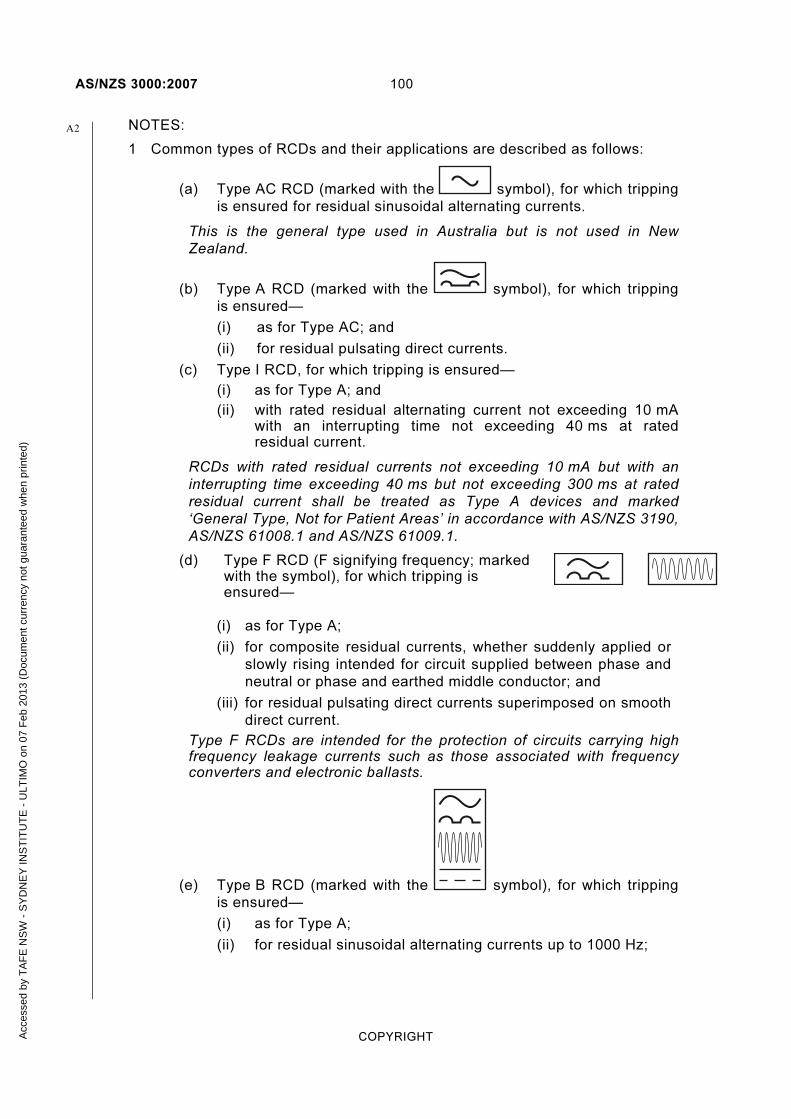
AS/NZS 3000:2007 100
COPYRIGHT
NOTES:
1 Common types of RCDs and their applications are described as follows:
(a) Type AC RCD (marked with the symbol), for which tripping
is ensured for residual sinusoidal alternating currents.
This is the general type used in Australia but is not used in New
Zealand.
(b) Type A RCD (marked with the symbol), for which tripping
is ensured—
(i) as for Type AC; and
(ii) for residual pulsating direct currents.
(c) Type I RCD, for which tripping is ensured—
(i) as for Type A; and
(ii) with rated residual alternating current not exceeding 10 mA with an interrupting time not exceeding 40 ms at rated residual current.
RCDs with rated residual currents not exceeding 10 mA but with an
interrupting time exceeding 40 ms but not exceeding 300 ms at rated
residual current shall be treated as Type A devices and marked
‘General Type, Not for Patient Areas’ in accordance with AS/NZS 3190,
AS/NZS 61008.1 and AS/NZS 61009.1.
(d) Type F RCD (F signifying frequency; marked with the symbol), for which tripping is ensured—
(i) as for Type A;
(ii) for composite residual currents, whether suddenly applied or
slowly rising intended for circuit supplied between phase and
neutral or phase and earthed middle conductor; and
(iii) for residual pulsating direct currents superimposed on smooth
direct current.
Type F RCDs are intended for the protection of circuits carrying high frequency leakage currents such as those associated with frequency converters and electronic ballasts.
(e) Type B RCD (marked with the symbol), for which tripping
is ensured—
(i) as for Type A;
(ii) for residual sinusoidal alternating currents up to 1000 Hz;
A2
Acc
esse
d by
TA
FE
NS
W -
SY
DN
EY
INS
TIT
UT
E -
ULT
IMO
on
07 F
eb 2
013
(Doc
umen
t cur
renc
y no
t gua
rant
eed
whe
n pr
inte
d)

101 AS/NZS 3000:2007
COPYRIGHT
(iii) for residual alternating currents or pulsating direct currents
superimposed on a smooth direct current of 0.4 times the
rated residual current (Idn); and
(iv) for residual direct currents that may result from rectifying
circuits.
(f) Type S RCD (S signifying selectivity and marked with the S
symbol), a specially designed RCD for which tripping is ensured
after a predetermined operating time delay corresponding to a
given value of residual current.
2 The waveform of a fault current to earth can affect the operation of an RCD and should be taken into account for the selection of the type of RCD.
IEC/TR 62350 Annex C contains a useful diagram of the likely form of the
fault currents generated from circuits utilizing a variety of semiconductor
devices and the selection of appropriate RCD types.
2.6.2.3 Protection against initiation of fire
Although not a mandatory requirement of this Standard, to provide additional protection against the initiation of fire caused by current leakage across insulation, a Type S RCD with a rated residual current in the range 100 mA to 300 mA may be used as a main switch in a domestic electrical installation, in addition to the requirements of Clause 2.6.3.
NOTE: Protection is not afforded to separated circuits typically used for extra-low voltage (ELV) lighting or against the initiation of fire from equipment operating at elevated temperatures.
2.6.2.4 Arrangement
Where additional protection of final subcircuits is required, in accordance with Clause 2.6.3, the final subcircuits shall be arranged as follows:
(a) In all electrical installations where—
(i) the number of RCDs installed exceeds one; and
(ii) more than one lighting circuit is installed
lighting circuits shall be distributed between RCDs
(b) In residential installations—
(i) not more than three final subcircuits shall be protected by any one RCD; and
(ii) where there is more than one final subcircuit, a minimum of two RCDs shall be installed
NOTE: These arrangements are intended to minimize the impact of the operation of a single RCD.
A1
A2
Acc
esse
d by
TA
FE
NS
W -
SY
DN
EY
INS
TIT
UT
E -
ULT
IMO
on
07 F
eb 2
013
(Doc
umen
t cur
renc
y no
t gua
rant
eed
whe
n pr
inte
d)

AS/NZS 3000:2007 102
COPYRIGHT
2.6.3 Where additional protection is required
2.6.3.1 Residential electric installations
Additional protection by RCDs with a maximum rated residual current of 30 mA shall be provided for final subcircuits supplying—
(a) one or more socket-outlets; and
(b) lighting points; and
NOTE: For the purpose of this Clause, combination fan, light and heater
units, smoke detectors, exhaust fans and ceiling sweep fans are all regarded
as lighting points.
(c) directly connected hand-held electrical equipment, e.g. directly connected hair dryers or tools;
forming part of—
(i) individual domestic electrical installations; or
(ii) residential areas of other electrical installations (see Note below); or
(iii) multiple residential electrical installations that are provided for common use; or
(iv) external lighting installations in common areas of multiple residential electrical installations.
Where protection of final subcircuits is required, RCDs shall be installed at the switchboard at which the final subcircuit originates.
Exceptions:
1 This requirement does not apply in medical treatment areas such as the home dialysis installations detailed in AS/NZS 3003.
2 This requirement need not apply to certain alterations, additions or repairs in accordance with Clause 2.6.3.4.
3 This requirement need not apply to a socket-outlet or a connecting device specifically for the connection of a fixed or stationary electric cooking appliance, such as a range, oven or hotplate unit, provided that—
(a) the socket-outlet is located in a position that is not likely to be accessed for general purposes; and
(b) the socket-outlet is clearly marked to indicate the restricted purpose of the socket-outlet and that RCD protection is not provided.
NOTE: Residential areas of other electrical installations include residential institutions, hotels, boarding houses, hospitals, accommodation houses, motels, hostels and the like.
A2
Acc
esse
d by
TA
FE
NS
W -
SY
DN
EY
INS
TIT
UT
E -
ULT
IMO
on
07 F
eb 2
013
(Doc
umen
t cur
renc
y no
t gua
rant
eed
whe
n pr
inte
d)

103 AS/NZS 3000:2007
COPYRIGHT
2.6.3.2 Other electrical installations
2.6.3.2.1 Australia
Additional protection by RCD s with a maximum rated residual current of 30 mA shall be provided for—
(a) final subcircuits supplying socket-outlets where the rated current of any individual socket-outlet does not exceed 20 A; and
(b) final subcircuits supplying lighting where any portion of the circuit has a rated current not exceeding 20 A; and
(c) final subcircuits supplying directly connected hand-held electrical equipment, e.g. hair dryers or tools.
NOTE: The final subcircuits referred to in Item (b) include, without limitation, those supplying the following equipment:
(a) External lighting installations, such as bollard-type luminaires.
(b) Illuminated signs.
(c) In-ground lighting.
(d) Ground-mounted lighting for the illumination of public features.
Exceptions: This requirement need not apply to the following:
1 Where other methods of protection are applied, e.g. a separated supply in accordance with Clause 7.4.
2 Where an RCD is incorporated into a socket-outlet or located adjacent to a socket-outlet and specifically intended for the protection of that socket-outlet the RCD shall interrupt all live (active and neutral) conductors.
3 Where specific provisions for electrical installations exist through the application of other Standards, e.g. AS/NZS 3001, AS/NZS 3002, AS/NZS 3003, AS/NZS 3004 and AS/NZS 3012.
4 To special situations referred to in Sections 6 and 7 of this Standard that require RCD protection, which shall be provided in accordance with the requirements of the relevant Clause.
5 Where the disconnection of a circuit by an RCD could cause a danger greater than earth leakage current.
6 Where all socket-outlets on a final subcircuit are installed for the connection of specific items of equipment, provided that—
(a) the connected equipment is required by the owner or operator to perform a function that is essential to the performance of the installation and that function would be adversely affected by a loss of supply caused by the RCD operation; and
(b) the connected equipment is designed, constructed and used in such a manner that is not likely to present a significant risk of electric shock; and
(c) the socket-outlet is located in a position that is not likely to be accessed for general purposes; and
A
A2
Acc
esse
d by
TA
FE
NS
W -
SY
DN
EY
INS
TIT
UT
E -
ULT
IMO
on
07 F
eb 2
013
(Doc
umen
t cur
renc
y no
t gua
rant
eed
whe
n pr
inte
d)

AS/NZS 3000:2007 104
COPYRIGHT
(d) the socket-outlet is clearly marked to indicate the restricted purpose of the socket-outlet and that RCD protection is not provided.
7 To a socket-outlet or a connecting device specifically for the connection of a fixed or stationary cooking appliance, such as a range, oven or hotplate unit.
In these applications, the socket-outlet shall be clearly marked to indicate the restricted purpose of the socket-outlet and that RCD protection is not provided. The socket-outlet shall be located in a position that is not likely to be accessed for general purposes.
Additional protection by RCDs with a maximum rated residual current of 30 mA also needs to be provided in accordance with the requirements and regulations of legislation, such as Occupational Health and Safety Legislation.
NOTE: In areas where excessive earth leakage current could present a significant risk in the event of failure of other measures of protection or carelessness by users, RCDs are designed to provide additional protection against the effects of electric shock by automatically disconnecting supply before serious physical injury can occur.
2.6.3.2.2 New Zealand
Additional protection by RCDs with a maximum rated residual current of 10 mA shall be provided for socket-outlets in areas within a building primarily for the purpose of teaching or caring for children in—
(a) kindergartens; and
(b) day care centres for preschool children; and
(c) schools for children up to and including school year eight.
Exceptions: This requirement need not apply to the following:
1 To socket-outlets mounted above 1.8 m from the floor or above 1.8 m from a platform that is accessible to children.
2 To socket-outlets specifically for the supply of electricity to information technology equipment or cleaning equipment that are clearly marked to indicate the restricted purpose of the socket-outlet and that RCD protection is not provided.
3 To socket-outlets in corridors, halls, gymnasiums and similar areas where portable electrical appliances are not likely to be used by children.
4 Where other methods of protection are applied, e.g. a separated supply in accordance with Clause 7.4.
5 Where specific provisions for RCD protection exist through the application of other Standards, e.g. AS/NZS 3001, AS/NZS 3002, AS/NZS 3003, AS/NZS 3004, or AS/NZS 3012.
6 To the special situations referred to in Sections 6 and 7 of this Standard that require RCD protection, which shall be provided in accordance with the relevant clause.
NZ
A2
Acc
esse
d by
TA
FE
NS
W -
SY
DN
EY
INS
TIT
UT
E -
ULT
IMO
on
07 F
eb 2
013
(Doc
umen
t cur
renc
y no
t gua
rant
eed
whe
n pr
inte
d)

105 AS/NZS 3000:2007
COPYRIGHT
2.6.3.3 Home medical patient treatment installations
In accordance with AS/NZS 3003, home medical electrical equipment installations shall be—
(a) supplied by a dedicated circuit; and
(b) protected by a Type I RCD, with a maximum rated residual current of 10 mA, positioned so that it may be reset by the patient while under treatment.
2.6.3.4 Alterations, additions and repairs
Where all of the circuit protection on a switchboard is replaced, additional protection by RCDs as required by this Clause 2.6 shall be provided for the final subcircuits supplied from that switchboard.
Socket-outlets that are added to an existing circuit shall be protected by an RCD.
Exceptions: The requirements of Clauses 2.6.3.1 and 2.6.3.2 need not apply to the following:
1 Where socket-outlets or lighting points that are not RCD-protected are replaced, including the replacement of a single socket-outlet with a multiple socket-outlet assembly.
2 Extensions to final subcircuits supplying lighting points only, provided that the existing final subcircuit is not RCD-protected.
3 Where socket-outlets are added to an existing subcircuit under circumstances where an exception from either Clause 2.6.3.1 or Clause 2.6.3.2 applies.
2.7 PROTECTION AGAINST OVERVOLTAGE
2.7.1 General
Where an electrical installation is protected against overvoltages that may cause danger to persons or property the requirements of Clauses 2.7.2 and 2.7.3 shall apply.
NOTES:
1 The causes of overvoltage in an electrical installation include the following:
(a) An insulation fault between the electrical installation and a circuit of higher voltage.
(b) Switching operations.
(c) Lightning.
(d) Resonant phenomena.
2 Protection against overvoltages is recommended in areas where lightning is prevalent.
2.7.2 Protection by insulation or separation
Measures to prevent danger because of faults between live parts of the electrical installation and circuits supplied at higher voltages shall consist of the following:
A2
Acc
esse
d by
TA
FE
NS
W -
SY
DN
EY
INS
TIT
UT
E -
ULT
IMO
on
07 F
eb 2
013
(Doc
umen
t cur
renc
y no
t gua
rant
eed
whe
n pr
inte
d)
AS/NZS 3000:2007 106
COPYRIGHT
(a) For conductors, the provision of adequate insulation screening or segregation of circuits in accordance with Clause 3.9.8.3.
(b) For transformers, the provision of adequate insulation, screening or separation of windings.
Transformer windings that operate at different voltages shall be insulated from one another by insulation with a specified test voltage or alternatively separated from one another by means of a conductive screen connected to the protective earthing conductor so as to ensure automatic disconnection of the supply in the event of a fault.
2.7.3 Protection by protective devices
Protective devices may be used to protect against the effects of overvoltage arising from such causes as lightning and switching operations.
Where installed such devices shall—
(a) limit the (transient) voltage to a value below the insulation level of the electrical installation or the part thereof that the device protects; and
(b) operate at voltages not less than or equal to the highest voltage likely to occur in normal operation; and
(c) cause no hazard to persons or livestock during operation.
NOTES:
1 This Standard does not require installations to be protected against overvoltages from lightning. Reference should be made to AS/NZS 1768 for information that will assist in determining the risk of lightning for particular applications and suitable protection methods.
2 This Standard does not require, surge protection devices (SPDs) to be installed. Appendix F is provided to give guidance on the appropriate selection and installation method for these devices.
2.8 PROTECTION AGAINST UNDERVOLTAGE
2.8.1 General
Suitable protective measures shall be taken where—
(a) the loss and subsequent restoration of voltage; or
(b) a drop in voltage;
could cause danger to persons or property.
Exception: Where potential damage to electrical equipment is considered an acceptable risk, undervoltage protection may be omitted.
NOTES:
1 Examples where the loss and subsequent restoration of voltage might cause danger include unexpected restarting of equipment, such as a guillotine, press or electrically operated gates (see also Clause 4.13 regarding protection of motors).
2 Failure to provide sufficient voltage will significantly reduce motor torque and will result either in an excessively long starting time, or, for extreme cases, in failure to start.
A1
Acc
esse
d by
TA
FE
NS
W -
SY
DN
EY
INS
TIT
UT
E -
ULT
IMO
on
07 F
eb 2
013
(Doc
umen
t cur
renc
y no
t gua
rant
eed
whe
n pr
inte
d)

107 AS/NZS 3000:2007
COPYRIGHT
The requirements of Clause 2.8.2 shall apply where an electrical installation is protected against undervoltage that may cause danger to persons or property.
NOTE: The causes of undervoltage in an electrical installation may include the following:
(a) Overload, or conductors of inadequate cross-section, producing excessive voltage drop.
(b) A fault in the high voltage supply system.
(c) Failure of, or high impedance in, a supply conductor.
2.8.2 Selection of protective device
The characteristics of the undervoltage protective device shall be compatible with the requirements of the appropriate Standards for starting and the use of electrical equipment.
Where the re-closure of a protective device is likely to create a dangerous situation, the re-closure shall not be automatic.
Instantaneous disconnection by the undervoltage device shall not be impaired by contacts that have intentional delays in their operation.
Exception: The operation of undervoltage protective devices may be delayed if the operation of the protected electrical equipment allows a brief interruption or loss of voltage without danger.
NOTES:
1 Protective devices having time-delay facilities should permit the starting of motors where the supply voltage exceeds 85% of rated voltage and continued operation where the voltage is within 10% of the rated voltage.
2 Examples of protective devices for undervoltage are—
(a) undervoltage relays or releases operating a switch or a circuit-breaker; and
(b) non-latched contactors.
2.9 SWITCHBOARDS
2.9.1 General
A switchboard or switchboards shall be provided in an electrical installation for the mounting or the enclosure of switchgear and protective devices.
Exception: This requirement need not apply to switchgear and protective devices, installed in a ground-mounted cable distribution cabinet in accordance with AS/NZS 3439.5, that protect small submains teed off larger submains forming an underground reticulated wiring system and to which unskilled persons do not require access.
A main switchboard shall be provided for each electrical installation for the primary control and protective devices of the electrical installation including the main switch or switches.
A1
Acc
esse
d by
TA
FE
NS
W -
SY
DN
EY
INS
TIT
UT
E -
ULT
IMO
on
07 F
eb 2
013
(Doc
umen
t cur
renc
y no
t gua
rant
eed
whe
n pr
inte
d)

AS/NZS 3000:2007 108
COPYRIGHT
Exception: A main switch need not be located on a switchboard, or be readily accessible, where unauthorized operation may impair safety and the electrical installation is—
(a) located on public land; and
(b) associated with telephone cabinets, traffic control signals and street furniture, such as bus shelters and the like; and
(c) otherwise controlled and protected, in accordance with the requirements of this Standard.
2.9.2 Location of switchboards
2.9.2.1 General
Switchboards shall be—
(a) installed in suitable well-ventilated places: and
(b) protected against the effects of moisture to which they may be exposed; and
(c) arranged so as to provide sufficient space for the initial installation and later replacement of individual items of the control and protective devices and accessibility for operation, testing, inspection, maintenance and repair.
2.9.2.2 Accessibility and emergency exit facilities
Switchboards shall be—
(a) located so that the switchboard and access to it is not obstructed by the structure or contents of the building or by fittings and fixtures within the building; and
(b) be provided with adequate space around the switchboard on all sides where persons are to pass to enable all electrical equipment to be safely and effectively operated and adjusted; and
NOTE: These requirements apply with switchboard doors in the open position and switchgear in a racked-out position to enable work on the switchboard to be performed safely and emergency exit facilities to be readily available.
(c) be provided with sufficient exit facilities to enable a person to leave the vicinity of a switchboard under emergency conditions.
Sufficient access and exit facilities are considered to be the provision of the following:
(i) Unimpeded space of at least 0.6 m around switchboards with switchgear doors in any position and large circuit-breakers racked out (see Figures 2.15 to 2.19).
(ii) Adequate alternative emergency exit paths, where a switchboard—
(A) has a prospective short-circuit current of not less than 15 kA; or
(B) is supplied by a circuit with a nominal capacity of not less than 800 A per phase; or
(C) is more than three metres in length.
A1
A1
Acc
esse
d by
TA
FE
NS
W -
SY
DN
EY
INS
TIT
UT
E -
ULT
IMO
on
07 F
eb 2
013
(Doc
umen
t cur
renc
y no
t gua
rant
eed
whe
n pr
inte
d)

109 AS/NZS 3000:2007
COPYRIGHT
(iii) Openings or doorways that are at least 0.75 m wide by 1.98 m high to allow persons necessary access to the switchboard room or enclosure.
NOTE: Larger openings may be required to enable entry of prefabricated switchboards.
Doors of switchrooms, or other rooms dedicated to switchboards, shall open in the direction of egress without the use, on the switchboard side of the door, of a key or tool.
Where more than one switchroom door is provided for access to the same switchboard, the doors should be spaced well apart.
Doors of enclosures dedicated to switchboards that open into a passage or narrow access way shall be capable of being secured in the open position to prevent workers being inadvertently pushed towards the switchboard.
Exception: The requirements for doors of switchrooms and for emergency exit facilities need not apply to single domestic electrical installations.
NOTE: Consideration should be given to providing means of escape from the immediate vicinity of the switchboard in more than one direction, in the event of an arcing fault occurring while work is in progress at the switchboard.
ACB
Rack out swi tchgear
L i f t of f pane ls
Hinged pane lor door
Fused swi tches (CFS )"Dead f ront"
0.6 m min.
0.6 m min.
0.6 m min.
0.6 m min.0.6 m min.
0.6 mmin.
0.6m min.
0.6m min.0.6m min.
0.6m min.
FIGURE 2.15 ACCESS TO SWITCHBOARDS—FREESTANDING SWITCHBOARD WITH RACK-OUT SWITCHGEAR
A1
Acc
esse
d by
TA
FE
NS
W -
SY
DN
EY
INS
TIT
UT
E -
ULT
IMO
on
07 F
eb 2
013
(Doc
umen
t cur
renc
y no
t gua
rant
eed
whe
n pr
inte
d)

AS/NZS 3000:2007 110
COPYRIGHT
0.6 m
FIGURE 2.16 ACCESS TO SWITCHBOARDS— SWITCHBOARD IN CORNER POSITION
0.6 m
0.6 m
0.6 m
FIGURE 2.17 ACCESS TO SWITCHBOARDS— SWITCHBOARD WITH ONE END AGAINST WALL
Acc
esse
d by
TA
FE
NS
W -
SY
DN
EY
INS
TIT
UT
E -
ULT
IMO
on
07 F
eb 2
013
(Doc
umen
t cur
renc
y no
t gua
rant
eed
whe
n pr
inte
d)

111 AS/NZS 3000:2007
COPYRIGHT
Passageway0.6 m 0.6 m
Bi-fo lddoor/s
FIGURE 2.18 ACCESS TO SWITCHBOARDS— SWITCHBOARDS WITH DOORS THAT OPEN INTO
ACCESSWAYS OR NARROW PASSAGEWAYS
NOTES: (to Figure 2.18)
1 Building and constructional parts must not obstruct access to switchboard (see Clause 2.9.2.2).
2 Clause 2.9.2.2 requires cupboard doors to be capable of being secured in the open position to prevent workers being inadvertently pushed towards the switchboard.
> 0.6 m
> 0.6 m
> 0.6 m
FIGURE 2.19 ACCESS TO SWITCHBOARDS— FACING SWITCHBOARDS
A1
Acc
esse
d by
TA
FE
NS
W -
SY
DN
EY
INS
TIT
UT
E -
ULT
IMO
on
07 F
eb 2
013
(Doc
umen
t cur
renc
y no
t gua
rant
eed
whe
n pr
inte
d)

AS/NZS 3000:2007 112
COPYRIGHT
2.9.2.3 Location of main switchboard
(a) General The main switchboard shall be readily accessible. The main switchboard, or a panel for the remote control of main switches in accordance with Clause 2.3.3.5, shall be located within easy access of an entrance to the building.
(b) Multiple electrical installations In multiple electrical installations the main switchboard shall not be located within any tenancy or single electrical installation of a multiple premise, either domestic or non-domestic.
2.9.2.4 Identification of main switchboard
The main switchboard shall be legibly and permanently marked ‘MAIN SWITCHBOARD’.
Where a main switchboard is located within a room or enclosure, any door required for immediate personal access shall be prominently and permanently marked to identify the room or enclosure in which the main switchboard is located.
The location of the main switchboard shall be legibly and permanently indicated by a conspicuous notice at each entry to the building that may be used by emergency services personnel.
Notices indicating the location of the main switchboard shall be of permanent construction and shall incorporate the term ‘MAIN SWITCHBOARD’ in contrasting colours.
Exceptions:
1 Identification of the main switchboard and its room or enclosure need not apply in a single domestic electrical installation.
2 The location of the main switchboard need not be marked at an entry to a building where the location is clearly indicated at a Fire Indicator Panel.
3 The location of the main switchboard need not be marked where the location can be readily determined, e.g. where it is clearly visible from the main entrance to the electrical installation.
NOTE: In New Zealand, any notice indicating the location of the main switchboard shall comply with the NZBC.
2.9.2.5 Restricted locations
Restricted locations for switchboards are as follows:
(a) Height above ground, floor or platform A switchboard shall not be located within 1.2 m of the ground, floor or platform.
Exception: A switchboard may be located within 1.2m of the ground, floor or platform if access to live parts is arranged, in accordance with the requirements of Clause 2.9.3.1.
NZ
A1
A1
Acc
esse
d by
TA
FE
NS
W -
SY
DN
EY
INS
TIT
UT
E -
ULT
IMO
on
07 F
eb 2
013
(Doc
umen
t cur
renc
y no
t gua
rant
eed
whe
n pr
inte
d)
113 AS/NZS 3000:2007
COPYRIGHT
(b) Water containers and fixed or stationary cooking appliances A switchboard shall not be installed above open water containers or fixed or stationary cooking appliances.
Exception: A switchboard may be located in an area that may be affected by water splashing or by steam, provided that the switchboard is provided with a suitable enclosure or is installed in a cupboard with close-fitting doors.
(c) In cupboards A switchboard installed in a cupboard or similar enclosure shall only be installed in an area set aside for the purpose.
The provisions of Clause 2.9.2.2 require that the switchboard be designed and located to provide ready access thereto for the purposes of operation and maintenance of equipment mounted on the switchboard. The following restrictions shall be applied to all switchboards, in particular, main switchboards.
The switchboard shall be—
(i) installed in a section of the cupboard separated from other sections; and
(ii) installed at the front of the switchboard section of the cupboard; and
(iii) facing the cupboard access door with insufficient unused space between the switchboard and the cupboard door, when closed, to store extraneous objects in front of the switchboard; and
(iv) arranged so that below the area of the switchboard panel or enclosure, there are no projections that obstruct access for the operation and maintenance of the switchboard.
(d) Near baths and showers A switchboard shall not be installed within any zone classified in accordance with Clause 6.2.2 for a bath or shower.
NOTE: Areas in the proximity of a shower are deemed unsuitable for switchboards because of the prevalence of high humidity and condensation.
(e) Near swimming pools, spas or saunas A switchboard shall not be installed within or above any zone classified in accordance with Clause 6.3.2 for a swimming pool or spa pool.
A switchboard shall not be installed within a sauna.
(f) Refrigeration rooms A switchboard shall not be installed within a refrigeration room.
(g) Sanitization or general hosing-down operations Switchboards installed in classified zones in locations subject to sanitization or hosing-down operations shall be provided with a minimum degree of protection of IPX6.
(h) Fire exits and egress paths Switchboards shall be located or arranged to minimize the impact of any smoke generated from a fault in the switchboard affecting egress from the building.
Acc
esse
d by
TA
FE
NS
W -
SY
DN
EY
INS
TIT
UT
E -
ULT
IMO
on
07 F
eb 2
013
(Doc
umen
t cur
renc
y no
t gua
rant
eed
whe
n pr
inte
d)
AS/NZS 3000:2007 114
COPYRIGHT
A switchboard shall not be installed within a fire-isolated stairway, passageway or ramp.
A switchboard may be installed within a cupboard, or similar compartment, in other forms of required exit, or in any corridor, hallway, lobby or the like leading to such an exit, provided that the cupboard or compartment doors are sealed against the spread of smoke from the switchboard.
NOTES:
1 The compartment may be the switchboard enclosure, provided that the enclosure provides a seal to the ingress of dust to at least IP5X and is provided with a facility to be kept locked in normal service.
2 These restrictions are based on the provisions of National Building Codes to which reference should be made for definition of the terms and for exceptions that may apply.
(i) Near fire-hose reels A switchboard shall not be installed within a cupboard containing a fire-hose reel.
NOTE: Information on the installation of fire hydrants and fire-hose reels in buildings is given in National Building Codes and AS 2419 series or NZS 4510 and AS 2441.
(j) Near automatic fire-sprinklers The following types of switchboards shall not be installed in the vicinity of an automatic fire-sprinkler system:
(i) Main switchboards.
(ii) Switchboards from which safety services originate in accordance with Clause 7.2.
Exception: A switchboard may be installed in the vicinity of an automatic fire sprinkler system if at least one of the following conditions is satisfied:
(A) The switchboard is provided with degree of protection IPX4, in accordance with AS 60529.
(B) The switchboard is provided with a shield to prevent water spraying on it.
(C) Sprinkler heads that could project water on the switchboard are provided with suitable deflectors.
(D) Sprinkler heads are of the dry type.
(k) Hazardous areas Switchboards shall not be installed in hazardous areas as defined in AS/NZS 60079.10.1 or AS/NZS 60079.10.2.
Exception: Switchboards constructed in accordance with AS/NZS 60079.14 may be installed within a hazardous area for which they are specifically designed.
A1
A2
A2
Acc
esse
d by
TA
FE
NS
W -
SY
DN
EY
INS
TIT
UT
E -
ULT
IMO
on
07 F
eb 2
013
(Doc
umen
t cur
renc
y no
t gua
rant
eed
whe
n pr
inte
d)
115 AS/NZS 3000:2007
COPYRIGHT
NOTES:
1 The following situations may give rise to a hazardous area:
(a) Heavier-than-air bottled gas cylinders with an aggregate gas capacity exceeding 30 m3 (e.g. liquid petroleum gas (LPG)).
(b) Gas-tank filling or discharge connections.
(c) Pressure relief device discharge points fitted to gas installations.
2 Refer to AS/NZS 60079.10.1 for information regarding hazardous areas.
3 An example of a hazardous area presented by a bottled heavier-than-air gas cylinder is shown in Figure 4.10 and in New Zealand only an example of a hazardous area presented by a reticulated (natural) gas system regulator is shown in Figure 4.11.
FIGURE 2.20 DELETED
2.9.3 Construction
2.9.3.1 Access to live parts
Live parts shall be arranged so that basic protection is provided by enclosures, in accordance with the provisions of Clause 1.5.4.
Exception: Live parts may be exposed in a non- domestic electrical installation provided that—
1 the live parts are arranged so that basic protection is provided by barriers in accordance with the provisions of Clause 1.5.4.4; or
2 the switchboard is installed in an area that is accessible only to authorized persons and the means of access to such areas is provided with facilities for locking.
In situations where the removal of covers and the like exposes live parts such covers shall be identified in accordance with AS/NZS 3439.
Exception: This requirement does not apply to domestic switchboards.
2.9.3.2 Suitability
Switchboards shall be suitable to withstand the mechanical, electrical and thermal stresses that are likely to occur in service.
Switchboards complying with the relevant requirements of the AS/NZS 3439 series of Standards are considered to meet the requirements of this Clause 2.9.3.
NOTES:
1 See also Clause 7.2.8.1 regarding segregation requirements for safety services.
2 See also Clause 2.5.5 regarding requirements for protection against the effects of arcing fault currents.
A1
A2
NZ
A2
Acc
esse
d by
TA
FE
NS
W -
SY
DN
EY
INS
TIT
UT
E -
ULT
IMO
on
07 F
eb 2
013
(Doc
umen
t cur
renc
y no
t gua
rant
eed
whe
n pr
inte
d)
AS/NZS 3000:2007 116
COPYRIGHT
2.9.3.3 Minimum clearances and creepage distances
All bare conductors and bare live parts of a switchboard shall be rigidly fixed so that a minimum clearance or creepage distance in air, in accordance with the AS/NZS 3439 series of Standards, is maintained between such conductors or parts of opposite polarity or phase and between such conductors or parts and earth.
Smaller values of clearances and creepage distances may be used—
(a) for individual items of manufactured electrical equipment complying with the relevant standard; or
(b) between a neutral bar or link and earth, provided that the neutral bar or link is insulated from earth.
2.9.3.4 Orientation of circuit-breakers
Where two or more circuit-breakers are mounted in the same row, the operating mechanism of each shall cause the circuit to open when the operating means are orientated in one general direction.
Exception: Other arrangements are permitted where the open circuit condition of each device is obvious or where each device is clearly marked to indicate the off position.
2.9.3.5 Screw-in fuses
Fuses using screw-in carriers shall be connected so that the centre contact is on the supply side of the fuse base.
NOTE: These fuses include Type D to AS 60269.3.1.
2.9.4 Bars or links
2.9.4.1 General
Bars or links shall be provided with facilities for securely terminating conductors in accordance with Clause 3.7.
2.9.4.2 Tunnel-type terminals
All screws that are in direct contact with conductors in tunnel-type terminals shall be of the type designed not to cut the conductor.
Where tunnel-type terminals having clamping screws that are in direct contact with the conductors are provided for connection of—
(a) the main incoming neutral conductor; or
(b) the main earthing conductor; or
(c) the connection between the main earthing terminal/connection or bar and the neutral bar (MEN connection); or
(d) a neutral conductor used as a combined protective earthing and neutral (PEN) conductor for protective earthing of any portion of an electrical installation,
the terminal shall be of a type having—
(i) two screws; or
A1
Acc
esse
d by
TA
FE
NS
W -
SY
DN
EY
INS
TIT
UT
E -
ULT
IMO
on
07 F
eb 2
013
(Doc
umen
t cur
renc
y no
t gua
rant
eed
whe
n pr
inte
d)

117 AS/NZS 3000:2007
COPYRIGHT
(ii) one screw with an outside diameter not less than 80% of the tunnel diameter.
NOTE: This requirement does not apply to connections arranged so that the conductor is clamped by suitable ferrules or plates in direct contact with the conductor.
2.9.4.3 Neutral bar or link
Every switchboard, to which a neutral conductor is connected, shall be provided with a neutral bar or link that is—
(a) of adequate current-carrying capacity; and
NOTE: The current-carrying capacity of the incoming neutral conductor may be used as a guide.
(b) located in an accessible position to allow all conductors to be safely connected without moving other cables or isolating the supply to the switchboard; and
(c) designed such that the incoming neutral conductor cannot be inadvertently disconnected from the bar or link; and
(d) provided with a separate terminal for—
(i) the incoming neutral conductor terminating at the switchboard; and
(ii) the neutral conductor(s) associated with each outgoing circuit originating at the switchboard.
Where tunnel-type terminals are provided, the provisions of Clause 2.9.4.2 shall apply.
A neutral conductor or busbar connection may be used between the neutral bar or link and a number of multi-pole devices mounted on the switchboard. Where such an arrangement is used the connection device shall comply with Clause 2.9.4.1 and, where appropriate, Clause 2.9.4.2.
Exception: Where the connection is made at a terminal of switchgear in accordance with the manufacturer's specifications, the provisions of Clauses 2.9.4.1 and 2.9.4.2 need not apply.
2.9.5 Equipment identification
2.9.5.1 General
All equipment installed on a switchboard shall be legibly and indelibly identified in the English language in accordance with the requirements of Clauses 2.9.5.2 to 2.9.5.6.
NOTE: See Clauses 2.3.3 and 2.3.4 for the marking requirements of main switches and additional isolating switches.
2.9.5.2 Relationship of electrical equipment
The relationship of switches, circuit-breakers, fuses, RCDs, and similar electrical equipment to the various sections of the electrical installation shall be marked on or adjacent to the switchboard.
A1
A2
Acc
esse
d by
TA
FE
NS
W -
SY
DN
EY
INS
TIT
UT
E -
ULT
IMO
on
07 F
eb 2
013
(Doc
umen
t cur
renc
y no
t gua
rant
eed
whe
n pr
inte
d)

AS/NZS 3000:2007 118
COPYRIGHT
The means of identification should be adequate to enable persons to readily identify equipment supplied and the corresponding circuit protective device.
2.9.5.3 Bars and links
Bars and links shall be identified to indicate whether they are active, neutral or earth.
Exception: Bars and links need not be identified at switchboards where the colour of the basic insulation of the conductors connected is visible and clearly indicates the nature of the bar or link.
2.9.5.4 Terminals of switchboard equipment
Terminals of bars, links, circuit-breakers, fuses and other electrical equipment mounted on a switchboard shall be marked or arranged to identify the corresponding active and neutral connection for each circuit.
The terminals for the connection of the MEN connection and for the main neutral conductor shall be legibly and indelibly marked at the main neutral bar or link.
Exception: This marking is not necessary where—
1 the MEN connection is made at a terminal at one extremity of the bar or link; and
2 the main neutral conductor is connected to the next adjacent terminal of the bar or link.
Where the MEN connection is made at another location, such as a substation, in accordance with Clause 5.3.5.1, the location of the connection shall be legibly and indelibly marked at the main switchboard.
2.9.5.5 Common neutral
Where a common neutral is used for two or more different circuits it shall be legibly and permanently marked to identify the associated active conductors.
NOTE: The requirements of Clause 2.2.1.2 also apply to the use of a common neutral conductor.
2.9.5.6 Fuse
Where the marking of the fuse base does not correctly indicate the rating of the associated fuse-element, the rating of the fuse-element shall be marked either on an exposed non-detachable portion of the fuse or on its enclosing case, or on the switchboard adjacent to the fuse.
A number of fuses may be marked as a group instead of independent marking adjacent to each fuse where—
(a) each fuse-element is of identical rating; and
(b) the fuses are mounted adjacent to each other.
A1
Acc
esse
d by
TA
FE
NS
W -
SY
DN
EY
INS
TIT
UT
E -
ULT
IMO
on
07 F
eb 2
013
(Doc
umen
t cur
renc
y no
t gua
rant
eed
whe
n pr
inte
d)

119 AS/NZS 3000:2007
COPYRIGHT
2.9.6 Wiring
Switchboard wiring shall be designed and installed to withstand any thermal and magnetic effects on the conductors.
Where provision is made to hinge or remove switchboard panels, all conductors connected to electrical equipment on the switchboard panel shall be—
(a) provided with sufficient free length to allow the panel to be moved into a position to enable work to be carried out; and
(b) suitably fixed or otherwise retained in position to avoid undue movement or stress at terminals of electrical equipment when the panel is moved or is fixed in position; and
(c) arranged to prevent undue pressure on electrical equipment mounted behind the panel.
2.9.7 Fire-protective measures
Wiring associated with switchboards shall be installed in such a manner that, in the event of fire originating at the switchboard, the spread of fire will be kept to a minimum.
Where a switchboard is enclosed in a case or surround, any wiring systems entering the switchboard enclosure shall pass through openings that provide a close fit.
NOTES:
1 See also Clause 2.9.2.5 (h) regarding restricted location of switchboards in or near egress paths or fire exits and Clause 3.9.9 regarding requirements to prevent the spread of fire.
2 There is a very high risk that wiring enclosures, especially those that enter at the top or sides of a switchboard, will contribute to the spread of fire and for this reason care needs to be taken to ensure that these wiring systems are provided with close-fitting entries. In some cases internal sealing should be provided.
3 An opening with less than 5 mm diameter of free space is considered to be a close fit. Therefore, any opening of 5 mm diameter or greater requires sealing with a fire-retardant sealant.
4 Wiring enclosures, such as conduits, having an internal free space of greater than 5 mm diameter also require sealing to stop any draft effect that could allow the spread of fire.
A2
Acc
esse
d by
TA
FE
NS
W -
SY
DN
EY
INS
TIT
UT
E -
ULT
IMO
on
07 F
eb 2
013
(Doc
umen
t cur
renc
y no
t gua
rant
eed
whe
n pr
inte
d)

AS/NZS 3000:2007 120
COPYRIGHT
S E C T I O N 3 S E L E C T I O N A N D I N S T A L L A T I O N O F W I R I N G S Y S T E M S
3.1 GENERAL
3.1.1 Application
The provisions of Section 3 form the minimum standard in relation to the selection and installation of wiring systems that must be achieved to satisfy Part 1 of this Standard.
3.1.2 Selection and installation
Wiring systems shall be selected and installed to perform the following functions associated with the safe design and construction and proper operation of the electrical installation:
(a) Protect against physical contact with live parts by durable insulation materials or by placing live parts out of reach.
(b) Satisfy current-carrying capacity, voltage drop and other minimum size requirements for conductors.
(c) Provide reliability and electrical continuity of connections, joints and terminations.
(d) Provide adequate strength of supports, suspensions and fixings.
(e) Suit intended use, including applications requiring a particular type of wiring system, e.g. fire-resistance, explosion protection, safety services.
(f) Protect against mechanical damage, environmental and other external influences by enclosure or other means.
Characteristics of wiring systems that are to be considered include conductor materials, core identification, insulation properties, temperature rise, bending and tension limitations.
3.2 TYPES OF WIRING SYSTEMS
The type of wiring system and method of installation used shall either—
(a) comply with Table 3.1; or
(b) have a degree of safety equivalent to that given in Table 3.1 and comply with the requirements of this Section.
Acc
esse
d by
TA
FE
NS
W -
SY
DN
EY
INS
TIT
UT
E -
ULT
IMO
on
07 F
eb 2
013
(Doc
umen
t cur
renc
y no
t gua
rant
eed
whe
n pr
inte
d)
121 AS/NZS 3000:2007
COPYRIGHT
3.3 EXTERNAL INFLUENCES
3.3.1 General
Wiring systems shall be able to operate safely and shall function properly in the conditions to which they are likely to be exposed at the point of installation.
Characteristics of wiring systems may comprise—
(a) suitable design and construction of the wiring system; or
(b) additional means, provided as part of the electrical installation, that do not adversely affect their operation;
to effectively protect against the presence and extent of relevant environmental and other influences.
NOTE: AS 60529 provides an IP Classification and marking system for electrical equipment and enclosures that provide different degrees of protection against the entry of water and solid objects (see Appendix G for illustrations).
3.3.2 Particular situations
3.3.2.1 Ambient temperature
Wiring systems shall be selected and installed so as to be suitable for the highest and lowest local ambient temperatures.
Where materials subject to temperature limitations are used above 60°C, or below 0°C, manufacturer’s instructions shall be followed.
Allowance shall be made for expansion of materials because of temperature variations that may occur in normal conditions of use.
Where current-carrying capacity is selected in accordance with the AS/NZS 3008.1 series, the reference ambient temperatures shall be as follows:
(a) For cables in air, irrespective of the method of installation:
(i) for Australia, 40°C; and
(ii) for New Zealand, 30°C.
(b) For cables buried direct in the ground or installed in underground enclosures:
(i) for Australia, 25°C; and
(ii) for New Zealand, 15°C.
A
A
NZ
NZ
Acc
esse
d by
TA
FE
NS
W -
SY
DN
EY
INS
TIT
UT
E -
ULT
IMO
on
07 F
eb 2
013
(Doc
umen
t cur
renc
y no
t gua
rant
eed
whe
n pr
inte
d)

AS
/NZ
S 3
00
0:2
00
7
12
2
CO
PY
RIG
HT
TABLE 3.1
CABLE TYPES AND THEIR APPLICATION IN WIRING SYSTEMS
Installation method Description Typical cable types
Unenclosed
On a surface (including cable tray or ladder)
Insulated and sheathed
Screened or armoured
Mineral insulated, metal sheathed (MIMS)
Earthing conductors
On a surface partly surrounded by thermal insulation
Fully surrounded by thermal insulation
Buried direct in the ground, subject to the requirements of Clause 3.11
Insulated and sheathed, screened or armoured, earthing conductors
In an enclosure On a surface (including cable trunking)
Insulated, unsheathed
Insulated and sheathed
Screened or armoured
MIMS
Earthing conductors
Accessed by TAFE NSW - SYDNEY INSTITUTE - ULTIMO on 07 Feb 2013 (Document currency not guaranteed when printed)

CO
PY
RIG
HT
12
3
AS
/NZ
S 3
00
0:2
00
7
On a surface and partly surrounded by thermal insulation
Fully surrounded by thermal insulation
Underground, subject to the requirements of Clause 3.11
Insulated, unsheathed Insulated and sheathed Screened or armoured Earthing conductors
Supported on a catenary system Insulated and sheathed Screened or armoured Earthing conductors
Supported on insulators Aerial conductors Earthing conductors
Accessed by TAFE NSW - SYDNEY INSTITUTE - ULTIMO on 07 Feb 2013 (Document currency not guaranteed when printed)

AS/NZS 3000:2007 124
COPYRIGHT
3.3.2.2 External heat sources
Wiring systems shall be protected against the effects of heat from external sources, including solar gain, by one or more of the following methods:
(a) Shielding.
(b) Placing sufficiently far from the source of heat.
(c) Selecting a system with due regard for the additional temperature rise that may occur.
(d) Limiting the current to be carried by the cable so as to reduce its operating temperature.
(e) Local reinforcement or substitution of insulating material.
(f) A method equivalent to one or more of those listed in Items (a) to (e).
Parts of a cable or flexible cord within an accessory, appliance or luminaire shall be suitable for the temperatures likely to be encountered, or shall be provided with additional insulation suitable for those temperatures.
3.3.2.3 Presence of water or high humidity
Wiring systems shall be selected and installed so that high humidity or the entry of water does not cause damage.
Where water may collect or condensation may form in a wiring system, to the extent that it creates a hazard, provision shall be made for its harmless escape through suitably located drainage points.
Where a wiring system may be subjected to wave action (water), protection against excessive flexing and mechanical damage shall be provided in accordance with Clauses 3.3.2.6, 3.3.2.7 and 3.3.2.8.
3.3.2.4 Presence of solid foreign bodies
Wiring systems shall be selected and installed so as to minimize the entry of solid foreign bodies during installation, use and maintenance.
In a location where dust or any other substance, in significant quantity, may be present, additional precautions shall be taken to prevent its accumulation in quantities that could adversely affect the heat dissipation from the wiring system.
3.3.2.5 Presence of corrosive or polluting substances
Where the presence of corrosive or polluting substances is likely to give rise to corrosion or deterioration, parts of the wiring system likely to be affected shall be suitably protected or manufactured from materials resistant to such substances.
Dissimilar metals liable to initiate galvanic action shall not be placed in contact with each other.
Materials liable to cause mutual or individual deterioration, or hazardous degradation, shall not be placed in contact with each other.
NOTE: The effect of substances, such as esters, ketones, ethers, aromatic and chlorinated hydrocarbons, should be considered when using insulating conduit, enclosures, cables or equipment.
A2
Acc
esse
d by
TA
FE
NS
W -
SY
DN
EY
INS
TIT
UT
E -
ULT
IMO
on
07 F
eb 2
013
(Doc
umen
t cur
renc
y no
t gua
rant
eed
whe
n pr
inte
d)

125 AS/NZS 3000:2007
COPYRIGHT
3.3.2.6 Impact
Wiring systems shall be selected and installed so as to minimize the risk of mechanical damage.
Protection against mechanical damage shall be provided by one or any combination of the following:
(a) Mechanical characteristics of the wiring system.
(b) Location selected.
(c) Provision of additional local or general mechanical protection.
3.3.2.7 Vibration
Wiring systems subject to vibration that is likely to cause damage to the wiring system, including all cables, fixings and connections, shall be suitable for the conditions.
3.3.2.8 Other mechanical stresses
Wiring systems shall be selected and installed so as to minimize damage to the cable insulation, sheathing and connections during installation, operation and maintenance.
Measures undertaken to minimize damage may include the following:
(a) Provision of supports, continuous or at appropriate intervals suitable for the mass of the cable.
(b) Use of suitable fixings for the cable size and type that hold the cable in position without damage.
(c) Use of suitable connections for the cable size and type that reduce mechanical strain at joints and terminations.
(d) Attention to minimum bending radius limits of cables.
(e) Provision of flexibility to accommodate any movement or tension stresses.
3.3.2.9 Presence of flora
Where the presence of flora is expected to constitute a hazard, either the wiring system shall be selected accordingly, or special protective measures shall be adopted.
3.3.2.10 Presence of fauna
Where the presence of fauna is expected to constitute a hazard, either the wiring system shall be selected accordingly, or special protective measures shall be adopted.
3.3.2.11 Solar radiation (direct sunlight)
Where a wiring system is, or may be, exposed to direct sunlight, either a wiring system suitable for the conditions shall be selected and installed, or adequate shielding shall be provided, in accordance with Clause 3.3.2.2.
Acc
esse
d by
TA
FE
NS
W -
SY
DN
EY
INS
TIT
UT
E -
ULT
IMO
on
07 F
eb 2
013
(Doc
umen
t cur
renc
y no
t gua
rant
eed
whe
n pr
inte
d)

AS/NZS 3000:2007 126
COPYRIGHT
NOTES:
1 Sheathed cables exposed to direct sunlight do not require further protection from UV radiation, unless otherwise advised by the manufacturer, as the sheath is considered to provide the necessary protection.
Black insulated unsheathed cables, e.g. aerial conductors, with UV-resistant insulation complying with AS/NZS 3808, do not require further protection.
For insulated unsheathed cables with insulation colours other than black, the manufacturer’s recommendation should be sought, or the cable should be provided with a physical barrier to prevent exposure to direct sunlight.
2 Guidance on the effect of direct sunlight on the current-carrying capacity of cables is given in the AS/NZS 3008.1 series. A correction factor for a temperature 20°C higher than the ambient air temperature may be applied.
3.3.2.12 Hazardous areas
Wiring systems installed in areas subject to explosive gas atmospheres and explosive dust atmospheres shall be selected and installed in accordance with Clause 7.7.
3.4 CURRENT-CARRYING CAPACITY
3.4.1 General
Every conductor shall have a current-carrying capacity, in accordance with the AS/NZS 3008.1 series, not less than the current to be carried by the conductor.
In determining the required current-carrying capacity, provision shall be made for reasonably foreseeable changes to external influences, such as the installation of thermal insulation in ceiling spaces and walls.
In New Zealand only, wiring systems in domestic installations shall be installed on the assumption that thermal insulation in ceilings, walls and under floors, if not currently installed, will be installed in the future.
NOTES:
1 Appendix C Paragraph C3 provides a set of current ratings that may be assigned to circuits in typical simple installations as an alternative to AS/NZS 3008.1 series. The ratings assign cable current-carrying capacities that are aligned with the current rating of protective devices.
2 National Building Codes contain mandatory requirements for the thermal insulation of ceilings and walls in certain situations.
3 The AS/NZS 5000 series of cable standards provide higher operating temperature materials for some cable insulation than was the case with their predecessors.
4 Current-carrying capacities for busbars should be obtained from the manufacturer. General guidance is given in AS 4388. Information relating to busways is given in AS/NZS 3439.2.
A2
NZA2
Acc
esse
d by
TA
FE
NS
W -
SY
DN
EY
INS
TIT
UT
E -
ULT
IMO
on
07 F
eb 2
013
(Doc
umen
t cur
renc
y no
t gua
rant
eed
whe
n pr
inte
d)

127 AS/NZS 3000:2007
COPYRIGHT
3.4.2 Operating temperature limits
The operating temperatures of conductors shall not exceed the limits given in Table 3.2.
Polymeric cables with normal use temperatures (see notes to Table 3.2) below 75o C are deemed not suitable for Australian or New Zealand conditions.
TABLE 3.2
LIMITING TEMPERATURES FOR INSULATED CABLES
Type of cable insulation (see Note 1)
Operating temperature of conductor, 0C
Normal use
(see Note 2)
Maximum permissible
(see Note 7)
Minimum ambient
(see Note 3)
Thermoplastic (see Note 4)
V-75 HFI-75-TP, TPE-75 V-90 HFI-90-TP, TP-90 V-90HT
75 75 75 75 75
75 75 90 90
105
0 -20
0 -20
0
Elastomeric
R-EP-90 R-CPE-90, R-HF-90, R-CSP-90 R-HF-110, R-E-110 R-S-150
90 90
110 150
90 90
110 150
-40 -20
* -50
Cross-linked polyethylene
X-90, X-90UV, X-HF-90 X-HF-110
90 110
90 110
* *
MIMS
(See Note 5)
100
250 Note 6
Other types
PE, LLDPE
70
70
*
* Refer to manufacturer’s information.
NOTES:
1 The types of cable insulation given in Table 3.2 are included in relevant specifications, i.e. the AS/NZS 5000 series, AS/NZS 3191, AS/NZS 3808 and AS/NZS 60702.1.
2 Lower maximum temperatures will apply where materials used in the construction of the cables or in association therewith, such as coverings, sheathings, insulating sleeving on connections and sealing compounds, have maximum operating temperatures lower than the cable proper. However, the allowable operating temperatures for such materials must not be exceeded.
3 If manufacturer’s recommendations permit, cables may be installed in locations where temperatures lower than specified may occur.
4 The normal operating temperature of thermoplastic cables, including flexible cords installed as installation wiring, is based on a conductor temperature of 75°C. This is because of the risk of thermal deformation of insulation if the cables are clipped, fixed or otherwise installed in a manner that exposes the cable to severe mechanical pressure at higher temperatures.
Acc
esse
d by
TA
FE
NS
W -
SY
DN
EY
INS
TIT
UT
E -
ULT
IMO
on
07 F
eb 2
013
(Doc
umen
t cur
renc
y no
t gua
rant
eed
whe
n pr
inte
d)

AS/NZS 3000:2007 128
COPYRIGHT
V-90 and V-90HT insulated cables may be operated up to the maximum permissible
temperatures of 90°C and 105°C, provided that the cable is installed in a manner that
is not subject to, or is protected against, severe mechanical damage for temperatures
higher than 75°C. Such applications also allow for cables to be installed in—
(a) locations where the ambient temperature exceeds 40°C, e.g. equipment wiring
in luminaires and heating appliances, or in roof spaces affected by high summer
temperatures; and
(b) locations affected by bulk thermal insulation that restricts the dissipation of heat
from the cable.
5 The current-carrying capacities for MIMS cables are based on an operating temperature of 100°C for the external surface of either bare metal-sheathed cables or served cables. Higher continuous operating temperatures are permissible for bare metal-sheathed cables, dependent on factors such as the following:
(a) The suitability of the cable terminations and mountings.
(b) The location of the cable away from combustible materials.
(c) The location of the cable away from areas where there is a reasonable chance
of persons touching the exposed surface.
(d) Other environmental and external influences.
6 The minimum temperature of use for MIMS cables depends on the cable seal used and manufacturer's recommendations should be followed.
7 Current-carrying capacities determined in accordance with the AS/NZS 3008.1 series do not take into account the effect of temperature rise on the terminals of electrical equipment that can result in the temperature limits of the insulation of cables in the vicinity of the terminals exceeding the limits specified in Table 3.2. In such cases reference should be made to warnings given in the electrical equipment Standards.
3.4.3 Conductors in parallel
Current-carrying capacities for circuits comprising parallel multi-core cables or groups of single-core cables may be determined from the sum of the current-carrying capacity of the various cables connected in parallel provided that—
(a) cables shall be not less than 4 mm2; and
(b) grouping of cables shall not affect the cooling of each parallel cable, or group, by the ambient air or the ground; and
(c) the load current sharing between each parallel cable, or group shall be sufficient to prevent overheating of any cable or group.
Example: Equal load current sharing may be achieved by the selection and installation of cables to give the same impedance for each cable in the group. This condition is satisfied when—
(i) conductors are of the same material and cross-sectional area with a minimum size of 4 mm2; and
(ii) cables follow the same route and achieve the same length; and
(iii) conductors of each parallel cable, or group, are effectively joined together at each end; and
(iv) the relative position of phase and neutral conductors in and between parallel groups takes account of mutual impedance.
Acc
esse
d by
TA
FE
NS
W -
SY
DN
EY
INS
TIT
UT
E -
ULT
IMO
on
07 F
eb 2
013
(Doc
umen
t cur
renc
y no
t gua
rant
eed
whe
n pr
inte
d)

129 AS/NZS 3000:2007
COPYRIGHT
Exception: Unequal load current sharing between cables or groups may be permitted, in accordance with Part 1 of this Standard, provided that the design current and overcurrent protection requirements for each cable or group are considered individually. IEC 60364-4-43 provides further information on the conditions under which this is permitted.
NOTE: The AS/NZS 3008.1 series provides recommended circuit configurations for the installation of parallel single-core cables in electrically symmetrical groups. The recommended method is to use trefoil groups containing each of the three phase conductors and neutral in each group.
3.4.4 Coordination between conductors and protective devices
In accordance with Clause 2.5.3, the continuous current-carrying capacity of the cables shall be coordinated with the current for which the circuit is designed and the type and current rating of the overload protective device.
Taking into account the different overload operating characteristics for fuses and circuit-breakers, the following condition shall be satisfied:
(a) The current rating of circuit-breakers shall not be greater than the cable current-carrying capacity (IB ≤ IN ≤ IZ , see Clause 2.5.3.1).
(b) The current rating of HRC fuses shall not be greater than 90% of the cable current-carrying capacity (IB ≤ IN ≤ 0.9 IZ, see Clause 2.5.3.1).
3.5 CONDUCTOR SIZE
3.5.1 General
The nominal cross-sectional area of conductors shall be not less than the values given in Table 3.3.
TABLE 3.3
NOMINAL MINIMUM CROSS-SECTIONAL AREA OF CONDUCTORS
Type of wiring system
Use of the circuit
Conductor
Material Cross-sectional
area mm2
Insulated conductors
Socket-outlets (see Exception 1)
Copper
2.5
Other circuits 1
Signal and relay control circuits 0.5
Bare conductors — Copper 6
Insulated flexible conductors
— Copper 0.75
Aerial wiring — Copper 6
Aluminium 16
Exceptions:
1 Smaller conductors may be used on subcircuits supplying socket-outlets, based on their suitability, in accordance with this Standard, and taking account of voltage drop, current-carrying capacity and reliability of connections.
A2
Acc
esse
d by
TA
FE
NS
W -
SY
DN
EY
INS
TIT
UT
E -
ULT
IMO
on
07 F
eb 2
013
(Doc
umen
t cur
renc
y no
t gua
rant
eed
whe
n pr
inte
d)

AS/NZS 3000:2007 130
COPYRIGHT
2 This Table does not limit cable sizes for extra-low voltage or switchboard wiring.
NOTE: The size of unprotected consumers mains should be coordinated with the electricity distributor.
3.5.2 Neutral conductor
The minimum size of the neutral conductor shall be as follows:
(a) Single-phase two-wire circuit The neutral conductor or conductors of a single-phase consumers main, submain or final subcircuit shall have a current-carrying capacity not less than—
(i) the current-carrying capacity of the associated active conductor; or
(ii) the total current to be carried, where there is more than one active conductor.
(b) Multiphase circuit The current-carrying capacity of the neutral conductor of a multiphase circuit shall not be less than that determined in accordance with the following:
(iii) Harmonic currents Where a consumers main, submain or final subcircuit supplies a substantial load that generates harmonic currents, e.g. fluorescent lighting, computers, soft starters, variable speed devices or other electronic devices, the third and any higher order harmonic current generated in the equipment shall be added to the maximum out-of-balance load to determine the current to be carried by the neutral conductor.
For this purpose the third and any higher order harmonic current in the neutral conductor shall be taken as 100% of the highest load-generating harmonic currents on any phase.
NOTES:
1 A harmonic current load that constitutes not less than 40% of the total load on any single-phase is regarded as substantial.
2 The third harmonic currents (and multiples thereof) are additive to the normal 50 Hz current to be carried. Therefore, it may be necessary for the capacity of a neutral conductor to be greater than that of the associated active conductors. Further information can be obtained from a number of sources including IEC 60364-5-52.
(iv) Consumers mains, submains and final subcircuits The current-carrying capacity of the neutral conductor of multiphase consumers mains, submains or final subcircuit shall be not less than that of the current-carrying capacity of the largest associated active conductor.
NOTE: Where more than one active conductor is connected to the one phase, the associated active conductor, for the purposes of this Clause, is the sum of the cross-sectional areas of all conductors connected to any one phase, e.g. conductors connected in parallel or separately metered portions of consumers mains operating on the same phase.
Acc
esse
d by
TA
FE
NS
W -
SY
DN
EY
INS
TIT
UT
E -
ULT
IMO
on
07 F
eb 2
013
(Doc
umen
t cur
renc
y no
t gua
rant
eed
whe
n pr
inte
d)

131 AS/NZS 3000:2007
COPYRIGHT
Exceptions:
1 Out-of-balance currents that may arise from the operation of protective devices and other similar abnormal conditions need not be considered.
2 The neutral conductor of a multiphase circuit may have a current-carrying capacity lower than that determined by this Clause, provided that a detection device is fitted and arranged so that the neutral current cannot exceed the current-carrying capacity of the neutral conductor.
3 The neutral conductor of a multiphase circuit may have a current-carrying capacity less than that of the largest associated active conductor, provided that the predominant load consists of multiphase equipment and the current-carrying capacity is not less than the maximum out of balance current, including any harmonic component.
(c) PEN conductors The minimum size of a combined protective earth and neutral (PEN) conductor of consumers mains, or of a submain to an outbuilding of an electrical installation forming a separate MEN installation in accordance with Clause 5.5.3.1, shall—
(i) comply with the requirements of Item (a) or Item (b), as appropriate; and
(ii) be not less than that of an earthing conductor as required by Clause 5.3.3.
3.5.3 Earthing conductor
The size of an earthing conductor shall be determined in accordance with Clause 5.3.3.
3.6 VOLTAGE DROP
3.6.1 General
Under normal service conditions, the voltage at the terminals of any power-consuming electrical equipment shall be not less than the lower limit specified in the relevant electrical equipment Standard.
Where the electrical equipment concerned is not covered by a Standard, the voltage at the terminals shall be such as not to impair the safe functioning of the electrical equipment.
3.6.2 Value
The cross-sectional area of every current-carrying conductor shall be such that the voltage drop between the point of supply for the low voltage electrical installation and any point in that electrical installation does not exceed 5% of the nominal voltage at the point of supply.
The value of current used for the calculation of voltage drop on a circuit need not exceed the—
(a) total of the connected load supplied through the circuit; or
A1
Acc
esse
d by
TA
FE
NS
W -
SY
DN
EY
INS
TIT
UT
E -
ULT
IMO
on
07 F
eb 2
013
(Doc
umen
t cur
renc
y no
t gua
rant
eed
whe
n pr
inte
d)

AS/NZS 3000:2007 132
COPYRIGHT
(b) maximum demand of the circuit; or
(c) current rating of the circuit protective device.
NOTES:
1 Motor-starting, solenoid-closing and other similar applications where high transient currents may be experienced that can significantly increase voltage drop are excluded from consideration.
2 A simplified method of estimating voltage drop is provided in Appendix C. Detailed information on choosing conductor sizes, taking into account voltage drop, is given in the AS/NZS 3008.1 series.
Exceptions:
1 For final subcircuits, with the load distributed over the whole of the length of the circuit (such as socket-outlets or lighting points), half the current rating of the protective device may be used as the value of current.
2 This Clause does not apply to high voltage or extra-low voltage circuits (see Clauses 7.6 and 7.5 respectively).
3 Where the point of supply is the low voltage terminals of a substation located on the premises containing the electrical installation and dedicated to the installation, the permissible voltage drop may be increased to 7%.
4 This limit need not apply to stand-alone systems, in accordance with Clause 7.3, that are designed such that the combination of the output voltage from the source, together with the voltage drop within the installation, does not result in the utilization voltage, at equipment and appliances intended to operate at low voltage, falling more than a total of 11% below the nominal supply voltage under normal operating conditions.
3.6.3 Conductors in parallel
The voltage drop for a circuit in which conductors are connected in parallel shall be taken as the voltage drop in one of the conductors when that conductor is carrying the current determined by dividing the value of the current of the circuit determined in accordance with Clause 3.6.2 by the number of conductors in parallel.
3.7 ELECTRICAL CONNECTIONS
3.7.1 General
Connections between conductors and between conductors and other electrical equipment shall provide electrical continuity, an appropriate level of insulation and adequate mechanical strength.
The method of joining or connecting cables shall be suitable for the application and ensure that the conductivity of the joint or connection is not less than that of the conductor.
There shall be no undue pressure on conductors or on the connection after the connection has been made.
Acc
esse
d by
TA
FE
NS
W -
SY
DN
EY
INS
TIT
UT
E -
ULT
IMO
on
07 F
eb 2
013
(Doc
umen
t cur
renc
y no
t gua
rant
eed
whe
n pr
inte
d)
133 AS/NZS 3000:2007
COPYRIGHT
3.7.2 Connection methods
3.7.2.1 General
3.7.2.1.1 Common requirements
The selection of the method of connection shall take account of the following factors, as appropriate:
(a) Material of the conductor and its insulation.
(b) Number and shape of the wires forming the conductor.
(c) Cross-sectional area of the conductor.
(d) Number of conductors being connected together.
(e) Temperature attained by terminals in normal service such that the effectiveness of the insulation of the conductors is not impaired.
(f) Prevention of entry of moisture and the siphoning of water through any cable or wiring enclosure.
3.7.2.1.2 Aluminium conductors
Connections to, and joints in, aluminium conductors shall be made using components specifically designed for the connection of aluminium conductors and techniques specified by the manufacturer.
When connecting aluminium conductors, the following special factors associated with aluminium should be considered:
(a) Removal of the aluminium oxide film from the conductors.
(b) The relative softness of aluminium.
(c) The different coefficient of linear expansion of aluminium and other metals.
(d) Avoiding contact with dissimilar metals that may initiate galvanic action.
3.7.2.2 Preparation for connection
The insulation on a conductor shall not be removed any further than is necessary to make the connection.
For connections between insulated conductors, the connection shall be insulated to provide a degree of insulation not inferior to that of the conductors. Any damaged insulation shall be reinstated.
3.7.2.3 Loosening of connections
3.7.2.3.1 General
Connections shall be made so that no loosening is likely because of vibration, alteration of materials or temperature variations to which the connections are likely to be subjected in normal service.
Acc
esse
d by
TA
FE
NS
W -
SY
DN
EY
INS
TIT
UT
E -
ULT
IMO
on
07 F
eb 2
013
(Doc
umen
t cur
renc
y no
t gua
rant
eed
whe
n pr
inte
d)

AS/NZS 3000:2007 134
COPYRIGHT
3.7.2.3.2 Crimp joints (compression joints)
Conductors joined or terminated by means of a crimp (compression) connection shall be securely retained within a suitable crimping device. The connection shall be made using a tool designed for the purpose and techniques specified by the manufacturer.
3.7.2.4 Mechanical connection devices
Mechanical connection devices that meet the following criteria may be used for the connection of conductors.
Such devices shall—
(a) comply with an appropriate Standard; and
(b) not be dependent upon compression of insulating material for an effective electrical connection; and
(c) have a short-circuit rating suitable for the application; and
(d) have a long-term current-carrying capacity not less than that of the conductors they are designed to connect; and
(e) if capable of being re-used, suffer no deterioration in performance when re-used; and
(f) include manufacturer’s information regarding their correct use or re-use for users when supplied; and
(g) be installed using the techniques specified by the manufacturer for the application.
3.7.2.5 Retention of stranded conductors
The ends of stranded conductors shall be secured by suitable means, so as to prevent the spreading or escape of individual strands. They shall not be soft-soldered before clamping under a screw or between metal surfaces.
3.7.2.6 Mechanical stress
All cables and conductors shall be installed so that there is no undue mechanical stress on any connection.
3.7.2.7 Soldered connections
Where a soldered connection is used, the design shall take account of creep, mechanical stress and temperature rise under fault conditions.
Soft-soldered connections shall not be clamped under a screw or between metal surfaces.
NOTE: Soldered connections are not permitted for aerial conductors in tension (see Clause 3.7.2.9.1).
3.7.2.8 Flexible cords
Joints shall not be made in flexible cords.
Exception: Joints in flexible cords may be made—
(a) in accordance with the requirements of Clauses 3.7.2.2 to 3.7.2.7 where used as installation wiring; or
A1
Acc
esse
d by
TA
FE
NS
W -
SY
DN
EY
INS
TIT
UT
E -
ULT
IMO
on
07 F
eb 2
013
(Doc
umen
t cur
renc
y no
t gua
rant
eed
whe
n pr
inte
d)
135 AS/NZS 3000:2007
COPYRIGHT
(b) by means of suitable cable couplers.
Connections between a flexible cord and installation wiring shall be made in a purpose-made device containing suitable screwed or crimped terminals.
Any flexible cord shall be installed so that undue stress on its connections because of a pull on the cord is alleviated by a pillar, post, grip, tortuous path, or other effective means. Knotting of the flexible cord shall not be acceptable for this purpose.
3.7.2.9 Aerial conductors
3.7.2.9.1 Joints and connections
The following limitations and additional requirements apply to joints and connections in aerial conductors:
(a) Connections or joints in aerial conductors in tension shall be made without soldering.
(b) Connections to aerial conductors shall be reliable and adequately protected against the effects of movement, exposure to direct sunlight and entry of moisture, and shall be as short as practicable.
(c) Where conductors of dissimilar metals are joined, means shall be taken to prevent galvanic action by the use of appropriate connecting devices.
3.7.2.9.2 Prohibited joints
Joints shall not be made in the following types of cable, when in tension:
(a) Parallel-webbed or insulated twisted aerial cables.
(b) Neutral-screened cables.
(c) Multi-core cables.
(d) Conductors of different metals.
3.7.2.10 Underground cables
Connections in underground wiring shall be sealed to prevent the entry of moisture.
3.7.2.11 Earthing conductors
(a) Soldered connections Where soldering is used for the jointing or connection of earthing conductors, the earthing conductors shall be retained in position by acceptable means independently of the solder.
(b) Tunnel-type connections All screws that are in direct contact with conductors in tunnel-type terminals shall be of the type designed not to cut the conductor.
Tunnel terminals shall be of a type having—
(i) two screws; or
(ii) one screw with an outside diameter not less than 80% of the tunnel diameter; or
Acc
esse
d by
TA
FE
NS
W -
SY
DN
EY
INS
TIT
UT
E -
ULT
IMO
on
07 F
eb 2
013
(Doc
umen
t cur
renc
y no
t gua
rant
eed
whe
n pr
inte
d)

AS/NZS 3000:2007 136
COPYRIGHT
(iii) the conductor clamped by suitable ferrules or plates in direct contact with the conductor;
to maintain effective clamping of conductors.
Exception: This requirement need not apply where one clamping screw, in direct contact with the conductor, is provided at the fixed terminals of electrical equipment, such as junction boxes, socket-outlets, and lampholders, provided that the screw is in direct contact with the conductor.
NOTE: Terminals in earth bars and links shall comply with Clause 2.9.4.2.
3.7.3 Joints in cables
Joints in cables shall be enclosed, e.g. in a junction box, to provide adequate protection against relevant external influences.
Exception: Joints in cables need not be enclosed, provided that the joint—-
(a) is not subjected to any undue strain; and
(b) is made in accordance with the requirements of Clause 3.7.2; and
(c) has any mechanical protection that was removed or damaged reinstated; and
(d) is insulated and sheathed to provide the equivalent of the original cable insulation and sheathing, including the requirements outlined in Clause 3.10.1.2.
3.7.4 Installation couplers
An installation coupler, enclosed or unenclosed, complying with the requirements of AS/NZS 61535, is a suitable method for the electrical connection of cables, including flexible cords, flexible cables and rigid (solid or stranded) cables.
NOTES:
1 Installation couplers are intended for permanent connection between sections of wiring, particularly in ‘soft’ wiring systems, and are considered equivalent to a junction box.
2 Installation couplers require a deliberate act to disengage the latching mechanism and are not intended to be engaged or disconnected under load or to be used as socket-outlets.
3.8 IDENTIFICATION
3.8.1 General
Installation wiring conductors shall be clearly identified to indicate their intended function as active, neutral, earthing or equipotential bonding conductors.
Where identification is achieved using the colour of the conductor insulation, the colours specified in Table 3.4 shall be used.
Conductors with green, yellow or green/yellow combination coloured insulation or sheathing shall not be used as active or neutral conductors in installation wiring.
A1
A2
Acc
esse
d by
TA
FE
NS
W -
SY
DN
EY
INS
TIT
UT
E -
ULT
IMO
on
07 F
eb 2
013
(Doc
umen
t cur
renc
y no
t gua
rant
eed
whe
n pr
inte
d)
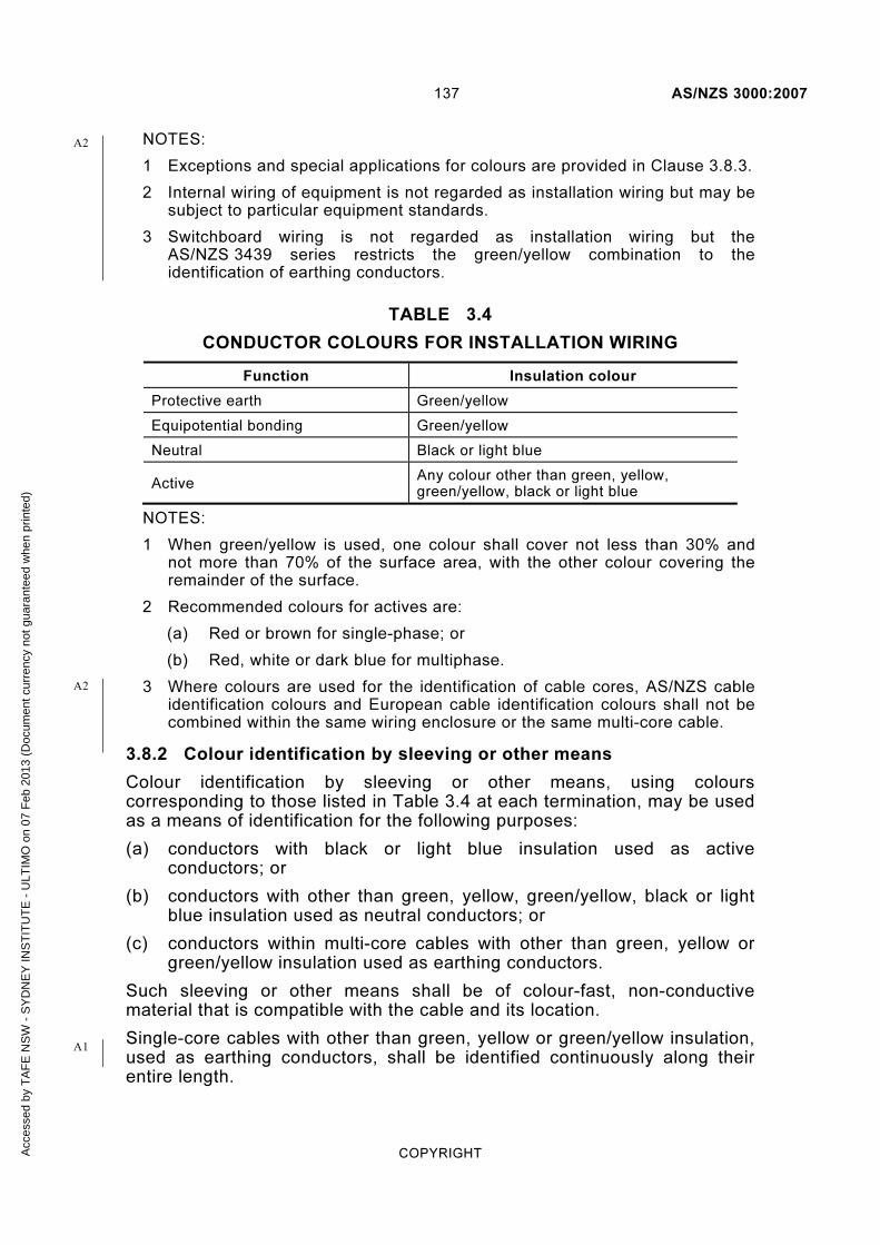
137 AS/NZS 3000:2007
COPYRIGHT
NOTES:
1 Exceptions and special applications for colours are provided in Clause 3.8.3.
2 Internal wiring of equipment is not regarded as installation wiring but may be subject to particular equipment standards.
3 Switchboard wiring is not regarded as installation wiring but the AS/NZS 3439 series restricts the green/yellow combination to the identification of earthing conductors.
TABLE 3.4
CONDUCTOR COLOURS FOR INSTALLATION WIRING
Function Insulation colour
Protective earth Green/yellow
Equipotential bonding Green/yellow
Neutral Black or light blue
Active Any colour other than green, yellow, green/yellow, black or light blue
NOTES:
1 When green/yellow is used, one colour shall cover not less than 30% and not more than 70% of the surface area, with the other colour covering the remainder of the surface.
2 Recommended colours for actives are:
(a) Red or brown for single-phase; or
(b) Red, white or dark blue for multiphase.
3 Where colours are used for the identification of cable cores, AS/NZS cable identification colours and European cable identification colours shall not be combined within the same wiring enclosure or the same multi-core cable.
3.8.2 Colour identification by sleeving or other means
Colour identification by sleeving or other means, using colours corresponding to those listed in Table 3.4 at each termination, may be used as a means of identification for the following purposes:
(a) conductors with black or light blue insulation used as active conductors; or
(b) conductors with other than green, yellow, green/yellow, black or light blue insulation used as neutral conductors; or
(c) conductors within multi-core cables with other than green, yellow or green/yellow insulation used as earthing conductors.
Such sleeving or other means shall be of colour-fast, non-conductive material that is compatible with the cable and its location.
Single-core cables with other than green, yellow or green/yellow insulation, used as earthing conductors, shall be identified continuously along their entire length.
A1
A2
A2
Acc
esse
d by
TA
FE
NS
W -
SY
DN
EY
INS
TIT
UT
E -
ULT
IMO
on
07 F
eb 2
013
(Doc
umen
t cur
renc
y no
t gua
rant
eed
whe
n pr
inte
d)
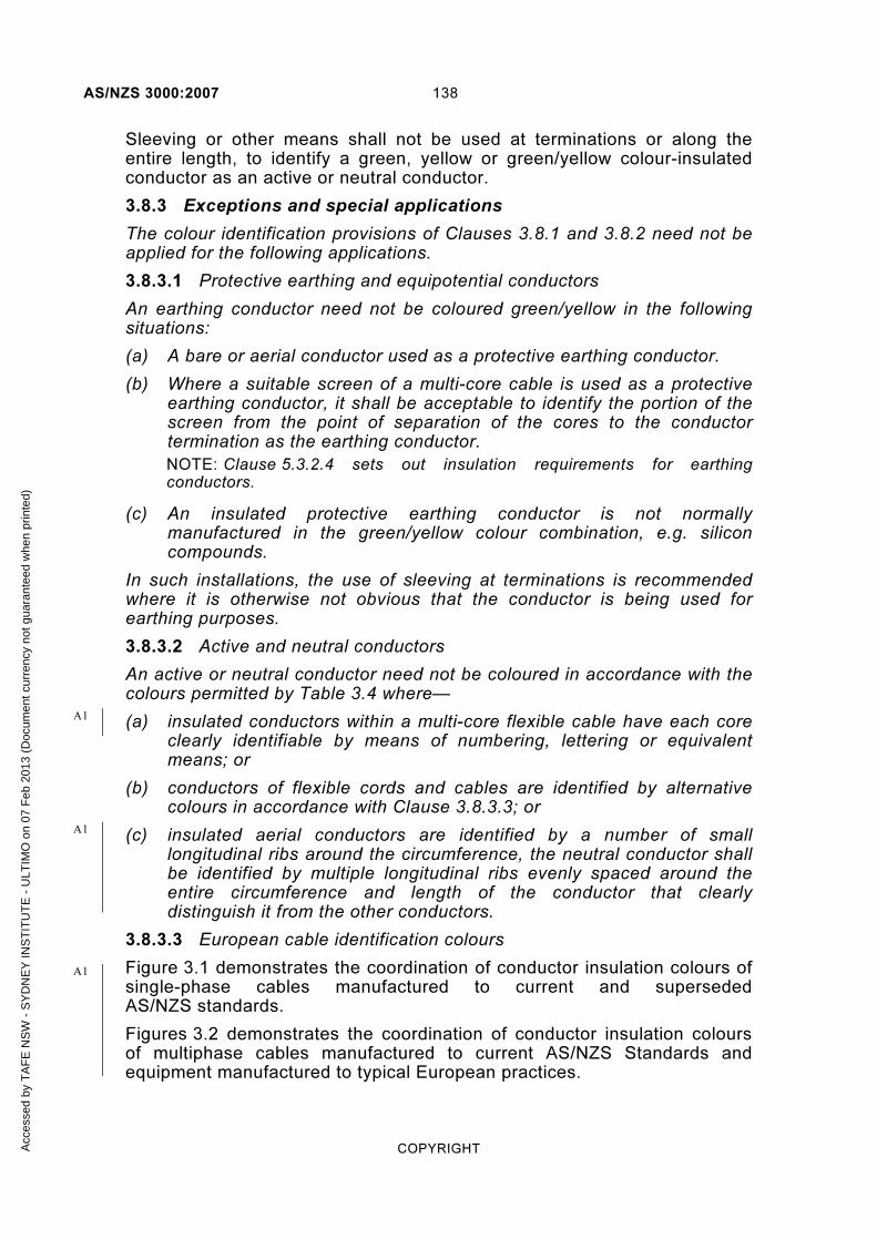
AS/NZS 3000:2007 138
COPYRIGHT
Sleeving or other means shall not be used at terminations or along the entire length, to identify a green, yellow or green/yellow colour-insulated conductor as an active or neutral conductor.
3.8.3 Exceptions and special applications
The colour identification provisions of Clauses 3.8.1 and 3.8.2 need not be applied for the following applications.
3.8.3.1 Protective earthing and equipotential conductors
An earthing conductor need not be coloured green/yellow in the following situations:
(a) A bare or aerial conductor used as a protective earthing conductor.
(b) Where a suitable screen of a multi-core cable is used as a protective earthing conductor, it shall be acceptable to identify the portion of the screen from the point of separation of the cores to the conductor termination as the earthing conductor.
NOTE: Clause 5.3.2.4 sets out insulation requirements for earthing conductors.
(c) An insulated protective earthing conductor is not normally manufactured in the green/yellow colour combination, e.g. silicon compounds.
In such installations, the use of sleeving at terminations is recommended where it is otherwise not obvious that the conductor is being used for earthing purposes.
3.8.3.2 Active and neutral conductors
An active or neutral conductor need not be coloured in accordance with the colours permitted by Table 3.4 where—
(a) insulated conductors within a multi-core flexible cable have each core clearly identifiable by means of numbering, lettering or equivalent means; or
(b) conductors of flexible cords and cables are identified by alternative colours in accordance with Clause 3.8.3.3; or
(c) insulated aerial conductors are identified by a number of small longitudinal ribs around the circumference, the neutral conductor shall be identified by multiple longitudinal ribs evenly spaced around the entire circumference and length of the conductor that clearly distinguish it from the other conductors.
3.8.3.3 European cable identification colours
Figure 3.1 demonstrates the coordination of conductor insulation colours of single-phase cables manufactured to current and superseded AS/NZS standards.
Figures 3.2 demonstrates the coordination of conductor insulation colours of multiphase cables manufactured to current AS/NZS Standards and equipment manufactured to typical European practices.
A1
A1
A1
Acc
esse
d by
TA
FE
NS
W -
SY
DN
EY
INS
TIT
UT
E -
ULT
IMO
on
07 F
eb 2
013
(Doc
umen
t cur
renc
y no
t gua
rant
eed
whe
n pr
inte
d)

139 AS/NZS 3000:2007
COPYRIGHT
NOTES:
1 Effective March 2006, British wiring practices were harmonized with Europe in relation to installation wiring and equipment wiring.
2 Care should be exercised when connecting imported equipment that does not use AS/NZS conductor colour codes and detailed testing is recommended to verify the function and connection of wiring within the equipment.
SUPERSEDED AS/NZS FLEXIBLE CORDS
FUNCTION EUROPEAN CABLES AND CURRENT AS/NZS FLEXIBLE CORDS, FLEXIBLE CABLES AND EQUIPMENT WIRING
Red
Black
Green
Act ive ...................................
.........................
........................
Neutra l
Ear th
Brown
Light b lue
Green /ye l low
FIGURE 3.1 SINGLE-PHASE CABLES
CURRENT AS/NZS CABLES FUNCTION EUROPEAN CABLES
Red
Whi te
Phase /L ine 1 ..........................
........................ Phase /L ine 2
Brown
Black
Black
Green / Ye l low
....................................
.............
Neutra l
Ear th
Blue
Blue ............................. Phase /L ine 3 Grey
Green /ye l low
FIGURE 3.2 MULTI-PHASE CABLES
NOTES:
1 The neutral core may or may not be included in multi-core cables and cords.
2 The alternative European active colour for multiphase flexible cords and cables on all phases is brown.
3.8.3.4 Aerial earthing conductors
Aerial earthing conductors shall be identified immediately adjacent to their termination at each end of the run either by the letter ‘E’ or by the earthing symbol.
A1
A1
Acc
esse
d by
TA
FE
NS
W -
SY
DN
EY
INS
TIT
UT
E -
ULT
IMO
on
07 F
eb 2
013
(Doc
umen
t cur
renc
y no
t gua
rant
eed
whe
n pr
inte
d)

AS/NZS 3000:2007 140
COPYRIGHT
3.9 INSTALLATION REQUIREMENTS
3.9.1 General
Wiring systems shall be installed in accordance with the generally accepted principles of safe and sound practice, using methods that will protect the electrical installation against mechanical or electrical failure under ordinary use, wear and tear, and any abnormal conditions that may reasonably be anticipated.
3.9.2 Methods of installation
Examples of acceptable types of wiring systems and methods of installation of wiring systems in relation to particular types of conductors or cables are depicted in Table 3.1.
Any methods used shall make allowances for the effect of external influences on the wiring system (see Clause 3.3).
NOTE: Types of wiring systems not covered in this Section may be used, provided that they comply with the general requirements of this Section.
Exception: The requirements of a relevant product Standard take precedence over this Clause.
3.9.3 Support and fixing
3.9.3.1 General
Wiring systems shall be supported by suitable means, in accordance with Clause 3.3.2.8.
Wiring systems shall be fixed in position, in accordance with this Standard, by suitable clips, saddles or clamps or by means that will not damage the wiring system and that will not be affected by the wiring system material or any external influences.
For wiring systems installed in building elements, the positioning and size of openings and checks shall not reduce the structural strength of those building elements below the levels required by National Building Codes.
NOTES:
1 Limits for the size of openings and checks made in structural members are contained in National Building Codes.
2 In New Zealand, this information may also be found in NZS 3604.
Where a wiring system consisting of sheathed cables is installed through metallic structural members, any aperture through which the cable passes shall be bushed or shaped to minimize abrasion of the cable. Where likely to be disturbed, the cable shall be fixed in position at a point adjacent to the aperture.
NOTE: Fixing of individual cores of a cable may be required where the risk of contact with conductive structural building materials exists (see Clause 5.4.6).
NZ
Acc
esse
d by
TA
FE
NS
W -
SY
DN
EY
INS
TIT
UT
E -
ULT
IMO
on
07 F
eb 2
013
(Doc
umen
t cur
renc
y no
t gua
rant
eed
whe
n pr
inte
d)

141 AS/NZS 3000:2007
COPYRIGHT
Exceptions:
1 Where a wiring system is resting on an immovable continuous surface no further support is required.
2 Any specific methods of fixing outlined in this Standard shall not prohibit the use of alternative methods, provided that an equivalent degree of support and strength is maintained.
3.9.3.2 Suspended ceilings
The following conditions apply to the installation of wiring systems in suspended ceilings—
(a) wiring systems may be supported by the suspended ceiling system unless this is not permitted by the suspended ceiling manufacturer; and
(b) cables shall be provided with additional protection against mechanical injury where in contact with conductive ceiling support runners; and
(c) wiring systems installed above suspended ceilings shall be fixed at suitable intervals to prevent undue sagging of cables.
NOTES:
1 Suspended ceilings referred to in this Clause do not include timber systems to AS/NZS 2589.1 and timber building Standards.
2 National Building Codes may restrict the use of suspended ceilings to support services.
3.9.3.3 Wiring systems likely to be disturbed
Wiring systems installed in the following locations are deemed likely to be disturbed and shall be supported at suitable intervals to prevent the undue sagging of cables:
(a) On the surface of a wall or on the underside of a ceiling or roof.
(b) In a space between a floor and the ground to which a person may gain entry.
(c) In a ceiling space having an access space exceeding 0.6 m high.
(d) Within two metres of any access to any space to which a person may gain entry.
(e) Below raised floors
Acc
esse
d by
TA
FE
NS
W -
SY
DN
EY
INS
TIT
UT
E -
ULT
IMO
on
07 F
eb 2
013
(Doc
umen
t cur
renc
y no
t gua
rant
eed
whe
n pr
inte
d)
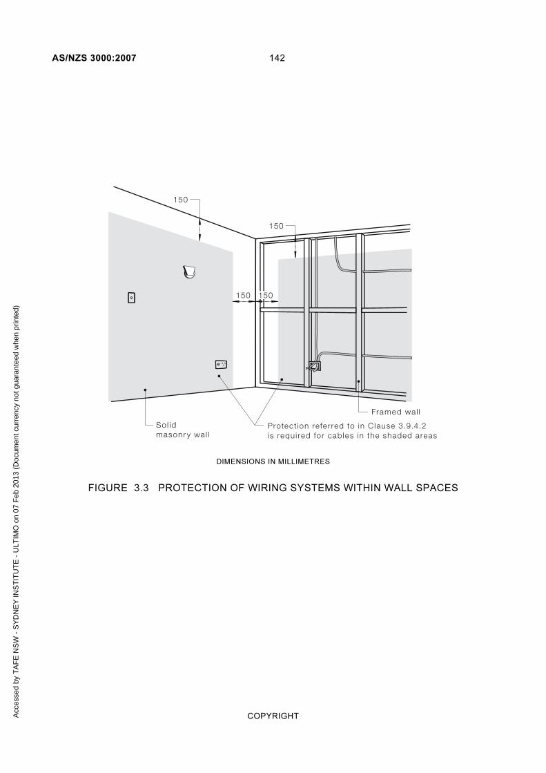
AS/NZS 3000:2007 142
COPYRIGHT
Protect ion refer red to in Clause 3.9.4.2is requi red for cables in the shaded areas
Sol idmasonr y wal l
Framed wal l
150
150
150 150
DIMENSIONS IN MILLIMETRES
FIGURE 3.3 PROTECTION OF WIRING SYSTEMS WITHIN WALL SPACES
Acc
esse
d by
TA
FE
NS
W -
SY
DN
EY
INS
TIT
UT
E -
ULT
IMO
on
07 F
eb 2
013
(Doc
umen
t cur
renc
y no
t gua
rant
eed
whe
n pr
inte
d)
143 AS/NZS 3000:2007
COPYRIGHT
The protect ion referred to inClause 3.9.4.2 is required for cablesin cavit ies i f they are f ixed or restrainedless than 50 mm from f in ished surfaces.This appl ies to each accessible s ide.
150 mm
FIGURE 3.4 PROTECTION OF WIRING SYSTEMS WITHIN CEILINGS, FLOORS AND WALL SPACES
Protect ion refer red to in Clause 3.9.4.2is requi red wi th in 50 mm of an access ib lesur face
FIGURE 3.5 PROTECTION OF WIRING SYSTEMS WITHIN CONCRETE ROOFS, CEILINGS OR FLOORS
3.9.4 Protection against mechanical damage
3.9.4.1 General
Wiring systems installed in positions where they may reasonably be expected to be subject to mechanical damage shall be adequately protected in accordance with Clause 3.3.2.6 and the applicable requirements of Clauses 3.9.4.2 to 3.9.4.4.
Acc
esse
d by
TA
FE
NS
W -
SY
DN
EY
INS
TIT
UT
E -
ULT
IMO
on
07 F
eb 2
013
(Doc
umen
t cur
renc
y no
t gua
rant
eed
whe
n pr
inte
d)

AS/NZS 3000:2007 144
COPYRIGHT
3.9.4.2 Wiring systems near building surfaces.
Wiring systems that are fixed in position by either fasteners or by passing through an opening in a structural member shall be protected by one of the methods outlined in Clause 3.9.4.4 if they are—
(a) concealed within 50 mm from the surface of a wall, floor, ceiling or roof; and
(b) located more than 150 mm from internal wall-to-wall or wall-to-ceiling corners.
Exception: These requirements need not apply to wiring systems that can move freely to a point not less than 50 mm from the surface in the event of a nail or screw penetrating the cavity at the location of the wiring system.
Figures 3.3 to 3.5 provide examples of protection of wiring systems near building surfaces.
3.9.4.3 Wiring systems under wall lining or roofing material
3.9.4.3.1 Prohibited locations
Wiring systems shall not be installed through any space formed between roofing or wall-lining material and its immediate supporting member (see Figure 3.6).
NOTE: Examples of these situations include those between tile battens and roofing tiles or between corrugated (or other profile) sheeting of a wall or roof and its supporting members are shown in Figures 3.6 and 3.7.
FIGURE 3.6 PROHIBITED CABLE LOCATION—ROOF OR WALL-LINING MATERIALS
3.9.4.3.2 Protection required
Wiring systems shall be protected by one of the methods outlined in Clause 3.9.4.4 if they pass through a structural member, or are fixed in position, within 50 mm from the face of the supporting member to which the lining or roofing material is attached (see Figure 3.7).
A1
A1
A1
A2
Acc
esse
d by
TA
FE
NS
W -
SY
DN
EY
INS
TIT
UT
E -
ULT
IMO
on
07 F
eb 2
013
(Doc
umen
t cur
renc
y no
t gua
rant
eed
whe
n pr
inte
d)

145 AS/NZS 3000:2007
COPYRIGHT
Protect ion refer red to inClause 3.9.4.2 is required i f the
cable is f ixed within 50 mm of theupper surface of the rafters or battens
(excluding the outer roof ing mater ia li tsel f ) or within 50 mm of the lower
surface of the cei l ing, i f any.
FIGURE 3.7 PROTECTION OF WIRING BELOW ROOFING MATERIAL
3.9.4.4 Protection methods
Where protection of a wiring system is required, in accordance with Clauses 3.9.4.2 and 3.9.4.3.2, the wiring system shall be—
(a) provided with adequate mechanical protection to prevent damage; or
(b) provided with an earthed metallic armouring, screen, covering or enclosure; or
(c) protected by an RCD with a maximum rated operating residual current of 30 mA.
3.9.5 Wiring systems installed vertically
Where wiring systems are installed vertically, they shall be installed in accordance with the requirements of Clauses 3.9.2 and 3.9.3 and in such a manner as to avoid damage to any part of the wiring system that may be caused by its own weight or method of support or fixing.
Adequate provision shall be made for the support of cables enclosed in a wiring enclosure installed vertically. Cable supports shall be provided at intervals not exceeding 8 m or as recommended by the cable manufacturer.
3.9.6 Change of direction
Where wiring systems change direction the following requirements shall apply:
(a) Bends shall not cause damage, or place undue stress on their sheathing, insulation, or terminations.
(b) The bending radius recommended by the cable manufacturer shall be observed.
Where manufacturer’s information is not available, the following minimum internal radii may be considered suitable—
(i) unarmoured sheathed cables ......... 6 times the cable diameter; or
(ii) armoured sheathed cables .............. 12 times the cable diameter.
(c) Supports in contact with cables under pressure from changes in direction shall not have sharp edges.
A1
A1
Acc
esse
d by
TA
FE
NS
W -
SY
DN
EY
INS
TIT
UT
E -
ULT
IMO
on
07 F
eb 2
013
(Doc
umen
t cur
renc
y no
t gua
rant
eed
whe
n pr
inte
d)

AS/NZS 3000:2007 146
COPYRIGHT
Exception: These requirements need not apply where the cable has been otherwise protected at the pressure point.
3.9.7 Particular requirements
3.9.7.1 Consumers mains
3.9.7.1.1 Protected
Consumers mains protected on the supply side by a short-circuit protective device shall comply with the relevant requirements of this Section
NOTE: The electricity distributor’s service protective device(s) may provide short-circuit protection.
3.9.7.1.2 Unprotected
Insulated, unsheathed cables enclosed in conductive wiring enclosures shall not be installed without short-circuit protection.
NOTE: Sheathing of cables is not required within conductive switchboard surrounds.
Consumers mains not provided with short-circuit protection on the supply side, shall—
(a) be constructed in such a manner as to reduce the risk of short-circuit to a minimum; and
(b) be installed in accordance with the relevant additional requirements of the electricity distributor.
The following wiring systems are deemed to reduce the risk of short-circuit to a minimum:
(i) Insulated and sheathed cables enclosed in heavy-duty insulating conduit to AS/NZS 2053.
(ii) Insulated and sheathed cables installed in underground wiring enclosures.
(iii) Aerial conductors consisting of XLPE cables type X-90UV to the AS/NZS 3560 series.
(iv) Busways and busbar systems, including joints and switchboard busbars, having insulation up to the first protective device in accordance with AS/NZS 3439 Series.
3.9.7.2 Insulated and sheathed cables
(a) Armoured sheathed cables Armoured sheathed cables may be installed in concrete, plaster or cement render without protection of a wiring enclosure.
(b) Unarmoured sheathed cables
(i) In concrete Unarmoured sheathed cables installed in concrete shall be contained within an appropriate wiring enclosure installed in accordance with Clauses 3.3.2.6 and 3.9.4.
Acc
esse
d by
TA
FE
NS
W -
SY
DN
EY
INS
TIT
UT
E -
ULT
IMO
on
07 F
eb 2
013
(Doc
umen
t cur
renc
y no
t gua
rant
eed
whe
n pr
inte
d)

147 AS/NZS 3000:2007
COPYRIGHT
(ii) In plaster or cement render Unarmoured sheathed cables may be installed in plaster or cement render without protection of a wiring enclosure, provided that the cables are installed and protected in accordance with Clauses 3.3.2.6 and 3.9.4.
3.9.7.3 Mineral insulated metal sheathed (MIMS) cable
(a) Protection against corrosion MIMS cables shall be protected by a suitable serving where they are—
(i) buried in concrete or plaster containing corrosive agents; or
(ii) installed underground, in accordance with Clause 3.11; or
(iii) in other locations where corrosion is likely to occur.
(b) Protection against vibration Movement caused by vibration shall be provided for by introducing a loop in the cable immediately before the termination.
The size of the loop shall be determined by the cable size and severity of the vibration.
(c) Support and fixing MIMS cable shall be supported and, if necessary, fixed in position so as to provide adequate protection against damage.
The supports and fixings shall be suitable for use at the highest temperature attained by the cable according to the circumstances of its use.
NOTE: See Clause 4.2.2.3 for requirements concerning the effect of elevated temperatures on adjacent materials.
3.9.7.4 Flexible cords used as installation wiring
Flexible cords used as installation wiring shall be of the heavy-duty sheathed type and installed in the same manner as insulated sheathed cables.
Exception: Flexible cords need not be of the heavy-duty type if—
(a) used for the connection of pendant socket-outlets; or
(b) installed in a suitable wiring enclosure; or
NOTE: See Clause 3.10.1 for requirements for enclosure of cables.
(c) installed for the connection of equipment, in accordance with the equipment wiring provisions of Clause 4.3.5.
Flexible cords installed as follows shall be regarded as installation wiring and shall comply with the requirements for installation wiring set out in this Section:
(i) Permanently connected flexible cords, including flexible cords used as pendants for socket-outlets and those connected to an installation coupler.
(ii) Flexible cords not open to view.
Acc
esse
d by
TA
FE
NS
W -
SY
DN
EY
INS
TIT
UT
E -
ULT
IMO
on
07 F
eb 2
013
(Doc
umen
t cur
renc
y no
t gua
rant
eed
whe
n pr
inte
d)

AS/NZS 3000:2007 148
COPYRIGHT
Exceptions:
1 Flexible cords used as pendants for lamps, luminaires or provided with, and permanently connected to an appliance, shall not be regarded as installation wiring.
2 Flexible cords installed for the connection of a single appliance or luminaire shall not be regarded as installation wiring, provided that they—
(i) do not exceed 2.5 m in length; and
(ii) have a current-carrying capacity of not less than:
(A) the current rating or setting of the circuit protective device; or
(B) the actual load of the appliance or luminaire, subject to the minimum cross-sectional area of any conductor being not less than 0.75 mm2.
3.9.7.5 Low voltage track systems
(a) Open to view A low voltage track system shall be installed so that the complete system is open to view throughout its entire length but not necessarily from one position.
(b) Position Track systems shall be installed so that the entry of dust or contamination is minimized.
(c) Supports The supports for a suspended track system shall be—
(i) of appropriate design; and
(ii) spaced at intervals not more than 1.5 m apart; and
(iii) arranged so that the system is held securely in position without sagging or undue stress.
Exception: Spacing specified by the system manufacturer shall take precedence over this requirement.
3.9.7.6 Under-carpet wiring systems
(a) Position An under-carpet wiring system shall be installed only as a floor-mounted arrangement under carpet tiles of a size not greater than 1 m × 1 m.
(b) Method of installation The under-carpet wiring system shall be installed in accordance with the manufacturer’s instructions only as a total system using specified component parts and installation tools.
Under-carpet wiring systems of differing configurations shall not be interconnected, e.g. to ensure that there is no interconnection between a five-core and a three-core system, the five-core system shall be connected only to a dedicated circuit.
Exception: Where manufacturer's instructions permit such interconnection this requirement need not apply.
Acc
esse
d by
TA
FE
NS
W -
SY
DN
EY
INS
TIT
UT
E -
ULT
IMO
on
07 F
eb 2
013
(Doc
umen
t cur
renc
y no
t gua
rant
eed
whe
n pr
inte
d)

149 AS/NZS 3000:2007
COPYRIGHT
3.9.8 Prevention of mutual detrimental effects between services
3.9.8.1 General
Wiring systems shall be selected and installed in accordance with Clauses 3.9.8.2 to 3.9.8.4 so as to avoid any detrimental effects arising from the installation and use of the wiring systems in the following situations:
(a) Between different electrical installations.
(b) Between different parts of the same electrical installation.
(c) Between circuits of an electrical installation operating at different voltages, such as extra-low voltage and low voltage.
(d) Between circuits of an electrical installation supplying different safety services.
(e) Between safety services and the remainder of the electrical installation.
NOTE: The regulations for safety services provide requirements for the segregation of such wiring systems from other wiring systems.
(f) Between electrical installations and non-electrical installations, such as gas and water supply.
(g) Between electrical installations and telecommunications and data cable installations.
3.9.8.2 Different electrical installations
(a) Common enclosure/cable Conductors that form part of different electrical installations shall not be installed within the same wiring enclosure or the same multi-core cable.
(b) Segregation Where conductors of different domestic or non-domestic portions of an electrical installation that form part of a multiple electrical installation terminate in a common enclosure, they shall be effectively segregated from each other within that enclosure.
NOTE: Effective segregation may be achieved by the use of independently sheathed cables, barriers of fire-resisting material or by distance.
Exception: These requirements need not apply to switchboards at which such circuits originate.
3.9.8.3 Segregation of different voltage levels
Cables of high voltage circuits and cables of low or extra-low voltage circuits shall not be enclosed in the same wiring system.
Cables of low voltage circuits and cables of extra-low voltage circuits may be enclosed in the same wiring system only where one of the following arrangements is employed:
(a) The low voltage cables shall be of a type providing the equivalent of double insulation.
(b) All cables or each conductor of a multi-core cable shall be insulated for the highest voltage present.
A1
A2
Acc
esse
d by
TA
FE
NS
W -
SY
DN
EY
INS
TIT
UT
E -
ULT
IMO
on
07 F
eb 2
013
(Doc
umen
t cur
renc
y no
t gua
rant
eed
whe
n pr
inte
d)

AS/NZS 3000:2007 150
COPYRIGHT
(c) The low voltage cables shall be installed in a separate compartment of a common cable trunking system having fixed and continuous barriers between compartments.
3.9.8.4 Proximity to non-electrical services
(a) General The following conditions shall be satisfied when installing electrical services:
(i) Wiring systems shall not be installed in the vicinity of services that produce heat, smoke or fumes likely to be detrimental to the wiring system.
Exception: Wiring systems may be installed in such locations where the wiring system is protected from harmful effects by shielding that does not affect the dissipation of heat from the wiring system.
(ii) Where a wiring system is situated below services liable to cause condensation (such as water, steam or gas services), precautions shall be taken to protect the wiring system from harmful effects.
(iii) Where electrical services are installed close to non-electrical services, they shall be so arranged that any reasonably foreseeable routine operation carried out on the other services will not cause damage to the electrical services.
NOTE: This may be achieved by suitable spacing between the services or the use of mechanical or thermal shielding.
(iv) Wiring systems shall be suitably protected against the hazards likely to arise from the presence of other services in normal use.
(v) Cables without sheathing or further enclosure shall not be installed in enclosures where they are accessible to personal contact or where they may contact other services, such as water, gas, hydraulic or communications systems.
NOTE: Metal parts of other services may require bonding to the earthing system in order to provide protection against earth faults, in accordance with Clause 5.6.2.3.
(b) Gas and water services Requirements for the separation of distributed gas and water systems from low voltage wiring systems are provided in the AS/NZS 5601 series for gas services and AS/NZS 3500 for water services.
Wiring systems shall maintain a separation of not less than 25 mm from any above-ground gas or water piping. Separation from underground gas and water services shall be in accordance with Clause 3.11.5.
Exception: This requirement does not apply to—
(A) an equipotential bonding conductor connected to the piping, in accordance with this or another Standard; or
(B) heat trace cabling.
A2
A1
Acc
esse
d by
TA
FE
NS
W -
SY
DN
EY
INS
TIT
UT
E -
ULT
IMO
on
07 F
eb 2
013
(Doc
umen
t cur
renc
y no
t gua
rant
eed
whe
n pr
inte
d)

151 AS/NZS 3000:2007
COPYRIGHT
(c) Telecommunication services Requirements for the separation of telecommunications cables from low voltage and high voltage systems are provided—
(i) for Australia, in AS/ACIF S009 Installation requirements for customer cabling (Wiring Rules); and
(ii) for New Zealand in the TCF Premises Wiring Code of Practice.
Separation from telecommunications services shall be as shown in Figures 3.8 and 3.9.
NOTE: These documents contain distances and other measures for the separation of telecommunications cables from low voltage cables as follows—
(a) on surfaces or concealed in walls, floors or ceilings, such as depicted in Figure 3.8;
(b) cables in common ducting;
(c) in underground trenches, such as depicted in Figure 3.9;
(d) under-carpet wiring; and
(e) aerial cables.
Barr ie r of durable insu lat ingmater ia l or ear thed meta l
50 mm min imum separat ion
LV cable
OR
Telecommunicat ionscable
Condui t is a lso anef fect ive barr ie r
FIGURE 3.8 SEPARATION OF LOW VOLTAGE CABLES AND TELECOMMUNICATIONS CABLES ON SURFACES OR CONCEALED IN
FLOORS OR CEILINGS
A
NZ
A1
A1
A2
Acc
esse
d by
TA
FE
NS
W -
SY
DN
EY
INS
TIT
UT
E -
ULT
IMO
on
07 F
eb 2
013
(Doc
umen
t cur
renc
y no
t gua
rant
eed
whe
n pr
inte
d)

AS/NZS 3000:2007 152
COPYRIGHT
Sharedtrench
LV cable inorange condui t
Te lecommunicat ions cablein whi te condui t
Min imum500 mm
In New Zealand,min imum 50 mm
separat ion requi red
LV
FIGURE 3.9 SEPARATION OF LOW VOLTAGE CABLES FROM TELECOMMUNICATIONS CABLES IN UNDERGROUND TRENCHES
3.9.9 Selection and installation to minimize the spread of fire
3.9.9.1 General
(a) Precautions shall be taken to minimize the spread of fire by the selection of appropriate materials and installation methods.
(b) Wherever electrical equipment contains flammable liquid in significant quantity, precautions shall be taken to prevent burning liquid and the products of combustion of the liquid (flame, smoke, toxic gases) spreading to other parts of the building.
NOTES:
1 Examples of such precautions are—
(a) a drainage pit to collect leakages of liquid and ensure their extinction in the event of fire; or
(b) installation of the equipment in a chamber of adequate fire-rating and the provision of sills or other means of preventing burning liquid spreading to other parts of the building, such a chamber being ventilated solely to the external atmosphere.
2 The generally accepted lower limit for a significant quantity is 25 L.
(c) In structures whose shape and dimensions facilitate the spread of fire, precautions shall be taken to ensure that the electrical installation cannot propagate a fire, e.g. chimney effect.
NOTE: Fire detectors may be provided that ensure the implementation of measures for preventing propagation of fire, e.g. the closing of fireproof shutters in ducts, troughs or trunking.
Acc
esse
d by
TA
FE
NS
W -
SY
DN
EY
INS
TIT
UT
E -
ULT
IMO
on
07 F
eb 2
013
(Doc
umen
t cur
renc
y no
t gua
rant
eed
whe
n pr
inte
d)

153 AS/NZS 3000:2007
COPYRIGHT
3.9.9.2 Precautions
(a) The risk of spread of fire shall be minimized by the selection of appropriate materials and installation.
(b) Wiring systems shall be installed so that the general building structural performance and fire safety are not reduced.
(c) Cables and products having the necessary fire-rating for wiring systems, in accordance with AS/NZS 3013, may be installed without special precautions.
(d) Cables not complying with the necessary fire-rating for wiring systems shall be limited to short lengths for connection of appliances to permanent wiring systems and shall not pass from one fire-segregated compartment to another.
3.9.9.3 Penetration of fire barriers
(a) Where a wiring system passes through elements of building construction, such as floors, walls, roofs, ceilings, partitions or cavity barriers that are required to be fire-rated—
(i) the opening shall be close-fitting to the wiring system and at least 50 mm from any other service opening; and
(ii) the cross-sectional area of the opening shall be not greater than 500 mm2, i.e. if circular, 25 mm diameter; and
Exception: The cross-sectional area of the opening may be increased up to a maximum of 2000 mm2 (50 mm diameter) for a single cable that leaves a gap of not more than 15 mm between the cable and the opening.
(iii) the fire-rating of structures shall be reinstated where openings remain after passage of the wiring system, in accordance with the relevant provisions of National Building Codes.
NOTES: Guidance on materials suitable for restoring fire-rated constructions is given in National Building Codes.
(b) Wiring systems, such as conduits, cable ducting, cable trunking, busbars or busbar trunking systems, and flush boxes that penetrate elements of building construction required to have a specified fire-rating shall be internally sealed to the degree of fire-rating of the respective element before penetration and externally sealed as required by Item (a).
(c) Conduit and trunking systems of material complying with the flame propagation test of AS/NZS 2053 or AS/NZS 4296, as appropriate, and having a maximum internal cross-sectioned area of 710 mm2 i.e.30 mm internal diameter, need not be internally sealed provided that—
(i) the system satisfies the degree of protection IP33; and
(ii) any termination of the system in one of the compartments separated by the building construction being penetrated satisfies the degree of protection IP33.
A1
Acc
esse
d by
TA
FE
NS
W -
SY
DN
EY
INS
TIT
UT
E -
ULT
IMO
on
07 F
eb 2
013
(Doc
umen
t cur
renc
y no
t gua
rant
eed
whe
n pr
inte
d)

AS/NZS 3000:2007 154
COPYRIGHT
(d) All sealing arrangements used in accordance with Items (a) to (c) shall comply with the following requirements.
Sealing arrangements shall—
(i) be compatible with the materials of the wiring system with which they are in contact; and
(ii) permit thermal movement of the wiring system without reduction of the sealing quality; and
(iii) be of adequate mechanical stability to withstand the stresses that may arise through damage to the support of the wiring system because of fire.
NOTE: This requirement may be satisfied if—
(a) either cable clamps or cable supports are installed within 750 mm of the seal, and are able to withstand the mechanical loads expected following the collapse of the supports on the fire side of the seal to the extent that no strain is transferred to the seal; or
(b) the design of the sealing system provides adequate support.
(e) Sealing arrangements intended to satisfy Items (a) and (b) above shall resist external influences to the same degree as the wiring system with which they are used and, in addition, shall meet the following requirements:
(i) They shall be resistant to the products of combustion to the same extent as the elements of building construction that have been penetrated.
(ii) They shall provide the same degree of protection from water penetration as that required for the building construction element in which they have been installed.
(iii) The seal and the wiring system shall be protected from dripping water that may travel along the wiring system, or that may otherwise collect around the seal, unless the materials used in the seal are all resistant to moisture when finally assembled for use.
NOTE: Materials and installation methods used for sealing will require the use of certified sealing products and installation methods.
3.9.10 Limitation of circulating and eddy currents
3.9.10.1 General
Precautions shall be taken to limit circulating and eddy currents.
3.9.10.2 Cables for a.c. circuits—Electromagnetic effects
Single-core cables armoured with steel wire or tape shall not be used for a.c. circuits.
Conductors of a.c. circuits installed in ferromagnetic enclosures shall be arranged so that the conductors of all phases and the neutral conductor (if any) and the appropriate protective earthing conductor of each circuit are contained in the same enclosure.
Acc
esse
d by
TA
FE
NS
W -
SY
DN
EY
INS
TIT
UT
E -
ULT
IMO
on
07 F
eb 2
013
(Doc
umen
t cur
renc
y no
t gua
rant
eed
whe
n pr
inte
d)

155 AS/NZS 3000:2007
COPYRIGHT
Where such conductors enter a ferrous enclosure they shall be—
(a) arranged so that the conductors are not individually surrounded by a ferrous material; or
(b) provided with other means of limiting any excessive heating effects of eddy (induced) currents.
NOTES:
1 Particular care must be taken where single-core cables carrying current in excess of 300 A pass through ferrous metal wall lining, switchboard surrounds, or similar ferrous enclosures.
2 The use of non-ferrous enclosures or gland plates or, where suitable, providing an air gap by slotting between individual core entries to break the magnetic circuit may be applied to eliminate this effect. A slot between individual core entries with a width of 20% of the individual core entries diameter is considered satisfactory.
3.9.10.3 Cables with non-ferrous metal sheathing
Single-core cables enclosed in lead, copper, aluminium or other non-ferrous metal sheathing may be used for alternating currents only where one of the following arrangements is employed:
(a) Trefoil formation
(i) The cables shall be run in trefoil formation throughout their entire length.
Exception: A distance not exceeding two metres at each end to facilitate termination of the cables is permitted.
(ii) The sheaths of the cables shall be bonded at the point where the trefoil formation ceases, or at the switchboard termination, and the bonding conductor conductivity shall be not less than that of the cable sheath.
(b) Other than trefoil formation
(i) The cables shall be placed as near as practicable to each other (they may be touching).
(ii) The sheathing of the cables shall be bonded at both ends and at intervals not exceeding 30 m along the cable run. The bonding conductor conductivity shall be not less than that of the cable sheath.
Exception: Where the sheathing of cables is provided with an overall continuous covering of insulating material (serving), the bonding need only be carried out at both ends.
3.9.11 Electromagnetic interference
Certain types of electrical installations, e.g. those containing sensitive electronic equipment or systems, may require minimization of electromagnetic interference arising from magnetic fields developed from current flowing in cables. This may be addressed by—
(a) selection of cables designed for low magnetic field emissions; or
Acc
esse
d by
TA
FE
NS
W -
SY
DN
EY
INS
TIT
UT
E -
ULT
IMO
on
07 F
eb 2
013
(Doc
umen
t cur
renc
y no
t gua
rant
eed
whe
n pr
inte
d)

AS/NZS 3000:2007 156
COPYRIGHT
(b) installation of cables in enclosures that contain or shield magnetic fields; or
(c) installation of cables in configurations that produce low magnetic fields.
NOTE: AS/NZS 3008.1 series details circuit configurations for the installation of parallel single-core cables in groups that produce reduced levels of magnetic field in comparison with other electrically symmetrical configurations.
3.10 ENCLOSURE OF CABLES
3.10.1 General
3.10.1.1 Insulated, unsheathed cables
Insulated, unsheathed cables shall be enclosed in a wiring enclosure throughout their entire length.
Exception: Wiring enclosures need not be provided for insulated, unsheathed cables installed—
(a) as aerial conductors, in accordance with Clause 3.12; or
(b) in an enclosed wall cavity between an accessory and a wiring enclosure or sheathing terminated within 100 mm of the hole over or within which the accessory is mounted; or
NOTE: This exception does not apply within a roof space.
(c) within switchboards, metering and similar enclosures, provided that such cables are not exposed to touch during normal switching or meter-reading operations; or
(d) as earthing or equipotential bonding conductors installed in accordance with Section 5; or
(e) as an extra-low voltage circuit, in accordance with Section 7.5.
3.10.1.2 Insulated and sheathed cables
Cables of a sheathed type need not be installed in a wiring enclosure.
Exception: Cables having insulation or sheath that does not meet the combustion propagation requirements of AS/NZS 5000 series Standards, e.g. polyethylene-insulated unsheathed cables, shall be installed in fire-rated enclosures.
Where the sheath of a cable is removed, the exposed cores of the cable shall be enclosed in accordance with Clause 3.10.1.1.
3.10.2 Wiring enclosures
3.10.2.1 Types
The following types of wiring enclosures may be used for the protection of cables requiring further enclosure as specified in Clause 3.10.1.
(a) Conduits to AS/NZS 2053, including:
(i) Steel conduits or other metal tubing or conduit.
(ii) Flexible metal conduit.
Acc
esse
d by
TA
FE
NS
W -
SY
DN
EY
INS
TIT
UT
E -
ULT
IMO
on
07 F
eb 2
013
(Doc
umen
t cur
renc
y no
t gua
rant
eed
whe
n pr
inte
d)

157 AS/NZS 3000:2007
COPYRIGHT
(iii) Rigid and flexible insulating conduit.
(iv) Corrugated insulating conduit.
(b) Cable trunking systems to AS/NZS 4296, with or without compound filling.
(c) Other wiring enclosures providing mechanical protection at least equivalent to those listed in Items (a) and (b).
Covers of wiring enclosures containing unsheathed cables shall be effectively retained in position and, where installed in a readily accessible position, shall not be removable without the use of tools.
3.10.2.2 Change of wiring enclosures
Any change from one type of wiring enclosure to another shall be made—
(a) at a switchboard; or
(b) by means of a suitable device that provides for the complete protection of the conductor insulation and for continuity of conductive wiring enclosures.
3.10.2.3 Entry of water
Wiring enclosures shall be—
(a) installed in a manner that will prevent water from entering electrical equipment and enclosures; and
(b) where exposed to the weather, provided with adequate means to prevent the entry of rain.
NOTE: The relationship between the height of each end of a wiring enclosure and the risk of entry of water should be considered, e.g. a conduit installed on a hill from an underground connection pit to a switchboard enclosure that is much lower than the connection pit.
3.10.3 Installation of wiring enclosures
3.10.3.1 General
Wiring enclosures shall be installed in accordance with safe and sound practice and provide adequate protection as required by Clauses 3.3 and 3.10.3.2 to 3.10.3.9.
3.10.3.2 Support
Wiring enclosures shall be supported by suitable means to prevent damage to the enclosure or any associated cables.
3.10.3.3 Continuity
Mechanical and electrical continuity of conductive enclosures shall be maintained.
Exception: Continuity of conductive enclosures need not be maintained where, in accordance with this Standard, the enclosure is not required to be earthed, e.g. the enclosure contains insulated and sheathed cables only.
Acc
esse
d by
TA
FE
NS
W -
SY
DN
EY
INS
TIT
UT
E -
ULT
IMO
on
07 F
eb 2
013
(Doc
umen
t cur
renc
y no
t gua
rant
eed
whe
n pr
inte
d)

AS/NZS 3000:2007 158
COPYRIGHT
3.10.3.4 Bending
The radius of every bend in a wiring system shall be such that conductors and cables will not suffer damage.
Bends in rigid conduit shall be such that the internal diameter is not significantly reduced.
Changes of direction in trunking, ducts or similar applications, shall permit the bending of cables laid therein, so as to comply with the requirements of this Clause.
NOTE: See Clause 3.9.6 for cable-bending requirements.
3.10.3.5 Passage for conductors
Where conductors or cables, including flexible cables and flexible cords, are to be threaded through conduits, tubes or channels, or passed through openings formed in metalwork, such tubes, channels, conduit ends or openings shall be of adequate size and shall—
(a) be provided with bushes that are securely fixed in position; or
(b) if not bushed, have no sharp angles or projecting edges that would be likely to damage a conductor or the insulation, braiding or sheathing of a cable.
3.10.3.6 Terminations
Terminations shall be arranged so that wiring enclosures terminate in, and are supported on, electrical equipment in such a manner as to fully protect the enclosed cables as they pass into the electrical equipment.
Each end of flexible conduit shall be securely anchored to the fixed conduit, structure or electrical equipment where it terminates.
3.10.3.7 Installation in direct sunlight
Rigid insulating conduit, conduit fittings and cable trunking systems installed in direct sunlight shall be—
(a) of a type designed for such use; or
(b) painted with a light-coloured water-based acrylic paint.
NOTES:
1 AS/NZS 2053.1 requires that conduits suitable for use in direct sunlight be marked with the letter ‘T’.
2 AS/NZS 4296 recommends that cable trunking systems suitable for use in direct sunlight be marked with the letter ‘T’.
3.10.3.8 Provision for expansion
Provision for expansion shall be provided in runs of rigid insulating conduit.
NOTE: The thermal expansion of rigid insulating conduit for a 10oC temperature rise is approximately 1 mm for each 1 m of length.
Acc
esse
d by
TA
FE
NS
W -
SY
DN
EY
INS
TIT
UT
E -
ULT
IMO
on
07 F
eb 2
013
(Doc
umen
t cur
renc
y no
t gua
rant
eed
whe
n pr
inte
d)

159 AS/NZS 3000:2007
COPYRIGHT
3.10.3.9 Cable trunking
Cable trunking installations shall comply with the following:
(a) Covers shall be able to be opened, where practicable.
(b) Covers shall be continuous when passing through walls or floors.
(c) Cable trunking shall be accessible through its entire length.
(d) Cables installed in a trunking shall not rely on any readily removable cover for support.
(e) Non-hygroscopic trunking shall be used to enclose insulated, unsheathed conductors.
(f) Live parts of accessories mounted on cable trunking shall be arranged so that basic protection is provided, in accordance with Clause 1.5.4.
NOTE: See Clause 3.9.9.3 for requirements for penetration of fire-rated constructions.
3.11 UNDERGROUND WIRING SYSTEMS
3.11.1 Suitability and protection
Cables installed underground shall be—
(a) suitable for the environment in which they are placed; and
(b) provided with protection against inadvertent damage likely to be caused by manual or mechanical excavation work; and
(c) provided with suitable warnings, marking or other means to minimize the risk of inadvertent damage likely to be caused by manual or mechanical excavation works.
3.11.2 Classification of wiring systems
Underground wiring systems are classified as one of three types.
The type of cable and form of enclosure determine the category assigned to the underground wiring system.
A Category A system is one where the wiring system is inherently suitable for installation below ground and no further mechanical protection is required.
A Category B system is one where the wiring system is suitable for installation below ground only with additional mechanical protection provided for the cable or cable enclosure.
A Category C system is one in which the wiring system is laid within a channel chased in the surface of rock.
Underground cables shall be—
(a) of a type specified in Column 1 of Table 3.5; and
(b) installed in accordance with a category of installation permitted in Columns 2 to 9 of Table 3.5.
A1
Acc
esse
d by
TA
FE
NS
W -
SY
DN
EY
INS
TIT
UT
E -
ULT
IMO
on
07 F
eb 2
013
(Doc
umen
t cur
renc
y no
t gua
rant
eed
whe
n pr
inte
d)

AS/NZS 3000:2007 160
COPYRIGHT
NOTE: Underground wiring systems do not include those that are—
(i) embedded in a concrete floor, slab or pad; or
(ii) laid on the surface of the ground either within the building or in outdoor locations; or
(iii) enclosed in a ventilated cable tunnel; or
(iv) enclosed in a trough with removable covers where air circulation is not restricted.
3.11.3 Arrangements
3.11.3.1 Category A underground wiring systems
Category A underground wiring systems recognized by this Standard comprise one of the following arrangements:
(a) A system where cables are enclosed in heavy-duty insulating conduit without further mechanical protection.
(b) A system where cables are enclosed in insulating wiring enclosures encased in concrete.
(c) A system where sheathed cables are enclosed in galvanized steel pipe without further mechanical protection.
NOTE: Metal conduits are not suitable for this purpose.
(d) A system where armoured sheathed cables or neutral-screened cables are buried direct in the ground without mechanical protection.
Examples of Category A underground wiring systems are given in Figures 3.10 to 3.12.
3.11.3.2 Category B underground wiring systems
Category B underground wiring systems recognized by this Standard comprise one of the following arrangements:
(a) A system where cables are enclosed in medium-duty insulating conduit with additional mechanical protection.
(b) A system where sheathed cables are buried direct in the ground with mechanical protection.
Mechanical protection for a Category B underground wiring system is detailed in Clause 3.11.4.3.
Examples of Category B underground wiring systems are given in Figures 3.13 to 3.15.
3.11.3.3 Category C underground wiring system
Category C underground wiring systems recognized by this Standard is where cables are chased in rock and covered with concrete.
NOTE: A Category A underground wiring system laid in a channel chased in rock, in accordance with Category C system requirements, may be deemed to be Category C.
An example of a Category C underground wiring system is given in Figure 3.16.
A1
Acc
esse
d by
TA
FE
NS
W -
SY
DN
EY
INS
TIT
UT
E -
ULT
IMO
on
07 F
eb 2
013
(Doc
umen
t cur
renc
y no
t gua
rant
eed
whe
n pr
inte
d)

CO
PY
RIG
HT
16
1
A
S/N
ZS
30
00
:20
07
TABLE 3.5
UNDERGROUND WIRING SYSTEM CATEGORIES
1 2 3 4 5 6 7 8 9
Method of protection
Type of cable
Heavy-duty
conduit*
Medium-duty
conduit* encased
in concrete
Heavy-duty fibre
cement conduit
Fibre cement conduit
encased in concrete
Medium- or heavy-duty galvanized
pipe
Medium-duty,
corrugated or flexible conduit*
Buried direct in
the ground with no
enclosure
Chased in rock with
no enclosure
Insulated, unsheathed conductors
A A NP NP NP B NP NP
Insulated and sheathed conductors
A A A A A B B NP
Sheathed, armoured and served cables
A A A A A A A C
Neutral-screened cables suitable for underground
A A A A A A A NP
Neutral-screened cables
A A A A A B B NP
Served MIMS cables A A A A A B B C
Aluminium sheathed or strip armoured cables with PVC sheath
A A A A A B B C
* These conduits and any associated fittings consist of insulating material only and do not have any conductive components.
KEY:
A
B
=
=
Category A wiring system
Category B wiring system
C
NP
=
=
Category C wiring system
Not permitted
A1
Accessed by TAFE NSW - SYDNEY INSTITUTE - ULTIMO on 07 Feb 2013 (Document currency not guaranteed when printed)

AS/NZS 3000:2007 162
COPYRIGHT
3.11.4 Installation requirements
3.11.4.1 General
Underground wiring systems shall be installed in accordance with the requirements of Clauses 3.11.4.2 to 3.11.4.6.
3.11.4.2 Unenclosed cables
Any Category A or Category B wiring system that comprises cables not installed in a wiring enclosure shall be laid on a bed of not less than 50 mm of sand or friable soil free of sharp stone and covered by not less than 50 mm of the same material.
3.11.4.3 Category B wiring system mechanical protection
Where an underground wiring system is classified as a Category B wiring system, additional mechanical protection shall be provided that shall—
(a) be placed not more than 75 mm above the wiring system; and
(b) be not less than 150 mm wide; and
(c) overlap the wiring system by at least 40 mm on each side; and
(d) consist of one or a combination of the following:
(i) Precast concrete slabs having a thickness of not less than 40 mm and a classification of not less than grade 20 in accordance with AS 3600 or NZS 3104.
(ii) Concrete slabs cast on-site having a thickness of not less than 100 mm.
(iii) A continuous concrete pour having a thickness of not less than 75 mm.
(iv) Fibrous cement slabs having a thickness of not less than 12 mm.
(v) Bricks manufactured specifically for the protection of electric cables.
(vi) Polymeric cable cover strip complying with AS 4702.
(vii) Other materials that offer the same degree of protection afforded by the materials in Items (i) to (vi).
3.11.4.4 Minimum depth of cover
Underground wiring systems shall be installed with the minimum depth of cover and protection specified in Table 3.6.
These dimensions shall apply between the upper surface of—
(a) the wiring system for a Category A or Category C system; or
(b) the additional mechanical protection of a Category B system,
and the upper surface of the ground or below any poured concrete laid on that surface (see Figures 3.10 to 3.16).
A1
Acc
esse
d by
TA
FE
NS
W -
SY
DN
EY
INS
TIT
UT
E -
ULT
IMO
on
07 F
eb 2
013
(Doc
umen
t cur
renc
y no
t gua
rant
eed
whe
n pr
inte
d)

163 AS/NZS 3000:2007
COPYRIGHT
TABLE 3.6
UNDERGROUND WIRING SYSTEMS—MINIMUM DEPTH OF COVER
Location of wiring system
Covering on surface of ground above wiring
system
Cat A system
Cat B system
Cat C system
Within confines of a building
Poured concrete of 75 mm minimum thickness
0 mm (directly below)
0 mm (directly below)
0 mm (directly below)
No surface covering or less than 75 mm thickness of concrete
500 mm 500 mm 50 mm
Elsewhere external to a building
Poured concrete of 75 mm minimum thickness
300 mm` 300 mm 50 mm
No surface covering or less than 75 mm thickness of concrete
500 mm 500 mm 50 mm
3.11.4.5 Identification of underground wiring
Wiring systems installed underground shall be identified by an orange marker tape complying with AS/NZS 2648.1. In order to provide early detection of the presence of underground wiring during excavation work, marker tape shall be positioned at approximately 50% of the depth of cover above the wiring system or any additional mechanical protection provided for that system.
Where the wiring system is chased in rock, orange marker tape shall be laid directly on top of the wiring system before the concrete is poured.
Exception: Where an underground wiring system is installed by means of boring, marker tape may be omitted, provided that the location of the wiring system is marked and recorded in a suitable permanent location that is readily available to any person involved with excavation work at the location of the wiring system. If a pipe is retained after boring operations, the use of an orange-coloured pipe or conduit is recommended.
Acc
esse
d by
TA
FE
NS
W -
SY
DN
EY
INS
TIT
UT
E -
ULT
IMO
on
07 F
eb 2
013
(Doc
umen
t cur
renc
y no
t gua
rant
eed
whe
n pr
inte
d)

AS/NZS 3000:2007 164
COPYRIGHT
75 mm (min imum) cont inuous poured concreteover underground cable pos i t ion
Cable bedding,see Note
Marker tape
300
50
150
50Categor y A wir ing system f rom Table 3.5
FIGURE 3.10 EXAMPLE OF A CATEGORY A WIRING SYSTEM WITH CABLE LOCATED BELOW POURED CONCRETE OF 75 MM MINIMUM THICKNESS
NOTE TO FIGURES 3.10 TO 3.16:
Refer to Clause 3.11.4.2 for bedding requirements for underground cables not installed in a wiring enclosure.
Ground leve l no cover ing on sur face of the ground or less than 75 mm cont inuous poured concrete
Marker tape
250
500
50
50Categor y A wir ing system f rom Table 3.5
Cable bedding,see Note
FIGURE 3.11 EXAMPLE OF A CATEGORY A UNDERGROUND WIRING SYSTEM WITH CABLE LOCATED BELOW NATURAL GROUND
A1
A1
Acc
esse
d by
TA
FE
NS
W -
SY
DN
EY
INS
TIT
UT
E -
ULT
IMO
on
07 F
eb 2
013
(Doc
umen
t cur
renc
y no
t gua
rant
eed
whe
n pr
inte
d)
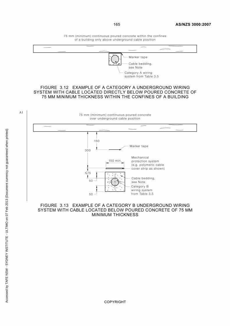
165 AS/NZS 3000:2007
COPYRIGHT
75 mm (min imum) cont inuous poured concrete wi th in the conf inesof a bu i ld ing only above underground cable pos i t ion
Marker tape
Categor y A wir ing system f rom Table 3.5
Cable bedding,see Note
FIGURE 3.12 EXAMPLE OF A CATEGORY A UNDERGROUND WIRING SYSTEM WITH CABLE LOCATED DIRECTLY BELOW POURED CONCRETE OF
75 MM MINIMUM THICKNESS WITHIN THE CONFINES OF A BUILDING
75 mm (min imum) cont inuous poured concreteover underground cable pos i t ion
Mechanica lprotect ion system(e.g. po lymer ic cablecover str ip as shown )
Marker tape
150
300
150 min.
75
Cable bedding,see Note
50
50
Categor y B wir ing system f rom Table 3.5
FIGURE 3.13 EXAMPLE OF A CATEGORY B UNDERGROUND WIRING SYSTEM WITH CABLE LOCATED BELOW POURED CONCRETE OF 75 MM
MINIMUM THICKNESS
A1
Acc
esse
d by
TA
FE
NS
W -
SY
DN
EY
INS
TIT
UT
E -
ULT
IMO
on
07 F
eb 2
013
(Doc
umen
t cur
renc
y no
t gua
rant
eed
whe
n pr
inte
d)
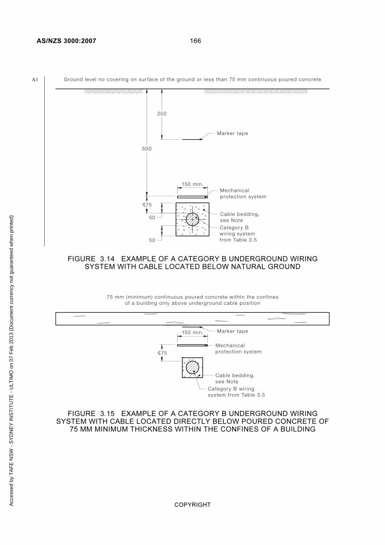
AS/NZS 3000:2007 166
COPYRIGHT
Ground leve l no cover ing on sur face of the ground or less than 75 mm cont inuous poured concrete
Marker tape
250
500
Mechanica lprotect ion system
150 min.
75
Cable bedding,see Note
50
50
Categor y B wir ing system f rom Table 3.5
FIGURE 3.14 EXAMPLE OF A CATEGORY B UNDERGROUND WIRING SYSTEM WITH CABLE LOCATED BELOW NATURAL GROUND
75 mm (min imum) cont inuous poured concrete wi th in the conf inesof a bu i ld ing on ly above underground cable pos i t ion
Categor y B wir ing system f rom Table 3.5
Marker tape
Cable bedding,see Note
Mechanica lprotect ion system
150 min.
75
FIGURE 3.15 EXAMPLE OF A CATEGORY B UNDERGROUND WIRING SYSTEM WITH CABLE LOCATED DIRECTLY BELOW POURED CONCRETE OF
75 MM MINIMUM THICKNESS WITHIN THE CONFINES OF A BUILDING
A1
Acc
esse
d by
TA
FE
NS
W -
SY
DN
EY
INS
TIT
UT
E -
ULT
IMO
on
07 F
eb 2
013
(Doc
umen
t cur
renc
y no
t gua
rant
eed
whe
n pr
inte
d)

167 AS/NZS 3000:2007
COPYRIGHT
Categor y C wir ing system f rom Table 3.5
50
ConcreteChase cut in rock
Marker tapeSol idrock
FIGURE 3.16 EXAMPLE OF A CATEGORY C UNDERGROUND WIRING SYSTEM
3.11.4.6 Marking and recording of underground cable location
To minimize damage to wiring systems installed underground during manual or mechanical excavation works, the location of underground wiring shall be marked or recorded as follows:
(a) Permanent cable marker signs shall be provided to indicate the point where a cable enters or leaves a structure; or
Exception: Cable entry signs need not be provided where the position of underground cable entry into the ground is obvious.
(b) The route of any underground cable shall be recorded on a plan to enable the location of the cable to be determined in the future. This plan shall be located at the switchboard from which the circuit originates. The plan locating the consumers mains shall be kept at the main switchboard of the installation to which it is connected.
Exception: Marking of underground wiring is not required within the confines of a building.
3.11.5 Spacing from other underground services
All underground wiring systems shall be spaced not less than 100 mm from other underground services.
Wiring systems shall be suitably marked with warning tape in accordance with Clause 3.11.4.5 and maintain a separation from telecommunications, gas and water services in accordance with Table 3.7.
Further requirements for the separation of telecommunications, gas and water systems from low voltage wiring systems are provided in Clause 3.9.8.4.
A1
A1
Acc
esse
d by
TA
FE
NS
W -
SY
DN
EY
INS
TIT
UT
E -
ULT
IMO
on
07 F
eb 2
013
(Doc
umen
t cur
renc
y no
t gua
rant
eed
whe
n pr
inte
d)
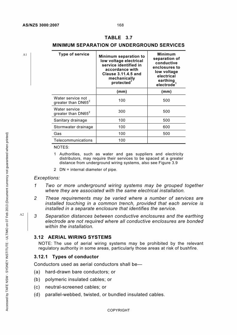
AS/NZS 3000:2007 168
COPYRIGHT
TABLE 3.7
MINIMUM SEPARATION OF UNDERGROUND SERVICES
Type of service Minimum separation to low voltage electrical service identified in
accordance with Clause 3.11.4.5 and
mechanically protected
1
Minimum separation of conductive
enclosures to low voltage
electrical earthing
electrode1
(mm) (mm)
Water service not greater than DN65
2 100 500
Water service greater than DN65
2
300 500
Sanitary drainage 100 500
Stormwater drainage 100 600
Gas 100 500
Telecommunications 100
NOTES:
1 Authorities, such as water and gas suppliers and electricity distributors, may require their services to be spaced at a greater distance from underground wiring systems, also see Figure 3.9
2 DN = internal diameter of pipe.
Exceptions:
1 Two or more underground wiring systems may be grouped together where they are associated with the same electrical installation.
2 These requirements may be varied where a number of services are installed touching in a common trench, provided that each service is installed in a separate enclosure that identifies the service.
3 Separation distances between conductive enclosures and the earthing electrode are not required where all conductive enclosures are bonded within the installation.
3.12 AERIAL WIRING SYSTEMS
NOTE: The use of aerial wiring systems may be prohibited by the relevant regulatory authority in some areas, particularly those areas at risk of bushfire.
3.12.1 Types of conductor
Conductors used as aerial conductors shall be—
(a) hard-drawn bare conductors; or
(b) polymeric insulated cables; or
(c) neutral-screened cables; or
(d) parallel-webbed, twisted, or bundled insulated cables.
A1
A2
Acc
esse
d by
TA
FE
NS
W -
SY
DN
EY
INS
TIT
UT
E -
ULT
IMO
on
07 F
eb 2
013
(Doc
umen
t cur
renc
y no
t gua
rant
eed
whe
n pr
inte
d)

169 AS/NZS 3000:2007
COPYRIGHT
3.12.2 Arrangements
3.12.2.1 Insulation of aerial conductors
Aerial conductors shall be insulated in the following situations:
(a) For any conductor span that is attached to a building or structure.
Exception: This requirement need not apply to aerial conductors between and supported by two independent poles or similar independent supports.
(b) For any conductor span within arms reach of any building, building opening or structure.
(c) Above areas where sailing craft or irrigation pipes are used (see Table 3.8).
(d) In areas declared by the responsible Fire Authority as being subject to bushfires, where required by the regulatory authority or the electricity distributor.
3.12.2.2 Minimum size
The minimum size of aerial conductors shall be as follows:
(a) Copper and aluminium conductors Copper or aluminium conductors installed as aerial conductors shall have not less than seven strands and shall be not smaller than 6 mm2
for copper or 16 mm2 for
aluminium.
(b) Steel conductors Steel conductors installed as aerial conductors shall have not less than three strands.
3.12.3 Clearances
3.12.3.1 General
Aerial conductors for low voltage systems shall be installed such that clearances from ground, buildings and structures other than public roadways are not less than those given in Table 3. 8
NOTE: These clearances do not apply to pole supports or independent supports for the aerial conductors themselves.
Clearances shall be maintained in any direction from any position to which any part of such conductors may either sag at a maximum conductor temperature of 115°C or move as a result of wind pressure.
When aerial conductors are being strung, an additional clearance shall be provided so that the distances specified in Table 3.8 are obtained up to a maximum conductor temperature of 115°C. An indication of an acceptable margin is given in Table D2 of Appendix D.
Where aerial conductors terminate above or to the side of a building or a structure, a suitable clearance to prevent contact with the building or a structure shall be provided.
A1
Acc
esse
d by
TA
FE
NS
W -
SY
DN
EY
INS
TIT
UT
E -
ULT
IMO
on
07 F
eb 2
013
(Doc
umen
t cur
renc
y no
t gua
rant
eed
whe
n pr
inte
d)

AS/NZS 3000:2007 170
COPYRIGHT
Connections between aerial conductors and circuit wiring shall not be regarded as aerial conductors but shall be out of arm’s reach from the ground or from an elevated area.
NOTE: Regulatory authorities may have additional requirements regarding aerial conductor clearances.
3.12.3.2 Safety warnings
Suitable devices or notices, warning of the presence of aerial conductors, shall be erected in locations where such conductors are erected—
(a) above areas used by sailing craft; or
(b) where long lengths of conductive piping, such as irrigation pipes, may reasonably be expected to be raised or otherwise handled; or
(c) where loading or unloading of high vehicles is likely to occur; or
(d) in other locations where the risk of inadvertent contact with aerial conductors may reasonably be anticipated.
NOTES:
1 The responsible water authority may have additional signage requirements where aerial conductors cross a waterway.
2 The relevant authority may require aerial conductors in the vicinity of an aerodrome, airport or landing strip to carry aircraft warning devices.
Acc
esse
d by
TA
FE
NS
W -
SY
DN
EY
INS
TIT
UT
E -
ULT
IMO
on
07 F
eb 2
013
(Doc
umen
t cur
renc
y no
t gua
rant
eed
whe
n pr
inte
d)
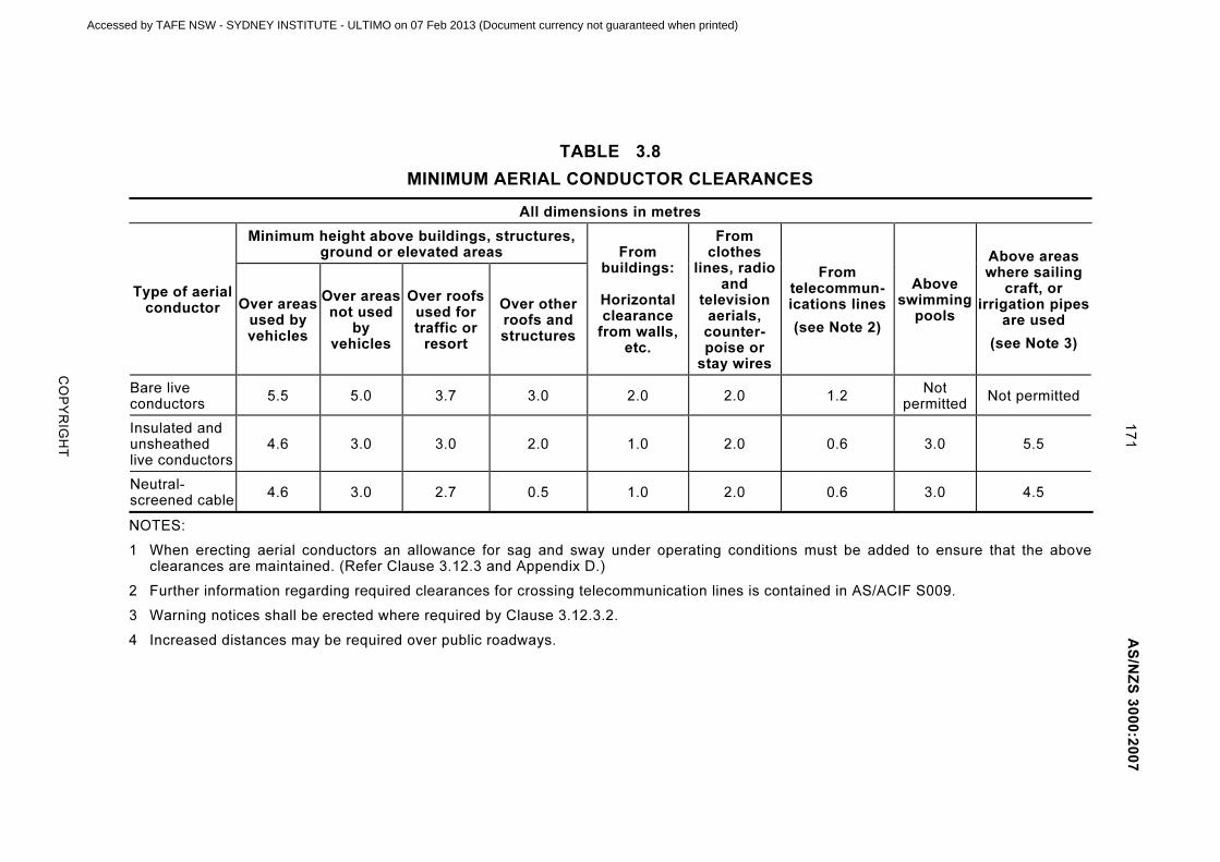
17
1
A
S/N
ZS
30
00
:20
07
CO
PY
RIG
HT
TABLE 3.8
MINIMUM AERIAL CONDUCTOR CLEARANCES
All dimensions in metres
Type of aerial conductor
Minimum height above buildings, structures, ground or elevated areas From
buildings:
Horizontal clearance
from walls, etc.
From clothes
lines, radio and
television aerials,
counter-poise or
stay wires
From telecommun-ications lines
(see Note 2)
Above swimming
pools
Above areas where sailing
craft, or irrigation pipes
are used
(see Note 3)
Over areas used by vehicles
Over areas not used
by vehicles
Over roofs used for traffic or
resort
Over other roofs and structures
Bare live conductors
5.5 5.0 3.7 3.0 2.0 2.0 1.2 Not
permittedNot permitted
Insulated and unsheathed live conductors
4.6 3.0 3.0 2.0 1.0 2.0 0.6 3.0 5.5
Neutral-screened cable
4.6 3.0 2.7 0.5 1.0 2.0 0.6 3.0 4.5
NOTES:
1 When erecting aerial conductors an allowance for sag and sway under operating conditions must be added to ensure that the above clearances are maintained. (Refer Clause 3.12.3 and Appendix D.)
2 Further information regarding required clearances for crossing telecommunication lines is contained in AS/ACIF S009.
3 Warning notices shall be erected where required by Clause 3.12.3.2.
4 Increased distances may be required over public roadways.
Accessed by TAFE NSW - SYDNEY INSTITUTE - ULTIMO on 07 Feb 2013 (Document currency not guaranteed when printed)

AS/NZS 3000:2007 172
COPYRIGHT
3.12.4 Distance between supports (spans)
The length of span of aerial conductors shall not exceed the values specified in Table 3.9 for the appropriate type and size of conductor.
Exception: Spans greater than the values specified in Table 3.9 may be used, provided that the design is in accordance with sound engineering practice.
NOTES:
1 An indication of acceptable stringing practice is given in Table D2 of Appendix D.
2 More detailed information is available in AS/NZS 7000.
TABLE 3.9
AERIAL CONDUCTOR MAXIMUM SPANS
Type of conductor Size
(mm2)
Maximum span (m)
Insulated annealed copper including neutral-screened ≥6 20
Bare hard-drawn copper ≥6 60
Insulated hard-drawn copper includingtwo-, three- and four-core twisted but excluding neutral-screened
6 10
≥16
40 50 60
Neutral-screened cables with hard-drawn copper conductors:
two conductors three conductors four conductors two, three, or four conductors
6 or 10 6 or 10 6 or 10
16
40 60 50 60
Insulated or bare aluminium excluding neutral-screened
16 ≥25
50 60
Aerial bundled cables (aluminium conductor) ≥25 60
3.12.5 Aerial conductor supports
3.12.5.1 General
Supports for aerial conductors shall be insulators or purpose-designed fittings suitable for the type of cable with which they are to be used.
3.12.5.2 Pin-type insulators
Pin-type insulators shall not be used for supporting aerial conductors where—
(a) the strain tends to lift or otherwise separate the conductors from the insulators; or
(b) the direction of the conductors is changed by more than 30°.
A2
Acc
esse
d by
TA
FE
NS
W -
SY
DN
EY
INS
TIT
UT
E -
ULT
IMO
on
07 F
eb 2
013
(Doc
umen
t cur
renc
y no
t gua
rant
eed
whe
n pr
inte
d)

173 AS/NZS 3000:2007
COPYRIGHT
3.12.5.3 Hardware
Any hardware or fittings used in association with the aerial line shall be of corrosion-resistant material, or other material suitably protected against corrosion.
3.12.5.4 Spacing between conductors
Conductors shall be adequately spaced to prevent contact with each other under all conditions of sag and sway.
The spacing between conductors at supports, measured in any direction, shall be not less than that shown in Table 3.10.
Exception: The spacing between conductors of a multi-core cable or cables operated in parallel may be less than that shown in Table 3.10.
NOTE: The electricity distributor may require a minimum clearance between consumers aerial lines and any electricity distributor aerial lines.
TABLE 3.10
SPACING BETWEEN AERIAL CONDUCTORS AT SUPPORTS
Span
Spacing (m)
Insulated conductors
Bare conductors
>10 >25 >45
≤10 ≤25 ≤45 ≤60
0.2 0.3 0.4 0.5
0.4 0.5 0.6 0.7
3.12.6 Poles and posts (including supports, struts and extensions to structures)
Poles and posts shall be constructed of materials suitable for the conditions of use, taking account of the following:
(a) Size Guidance on the size of a typical range of poles and posts is given in Appendix D.
(b) Depth in ground Guidance on the depth in ground for a typical range of poles and posts of lengths up to seven metres above the ground is given in Appendix D.
The depth in ground may be reduced if the pole is set in solid rock, provided that the arrangement is not inferior to those installed in accordance with the above requirements.
If the support of the soil is poor, the pole should be sunk to a greater depth or other means used to stabilise the pole.
NOTE: More detailed information is available in AS/NZS 7000.
3.12.7 Joints and connections
All joints and connections in aerial conductors shall be carried out in accordance with Clause 3.7.
A2
Acc
esse
d by
TA
FE
NS
W -
SY
DN
EY
INS
TIT
UT
E -
ULT
IMO
on
07 F
eb 2
013
(Doc
umen
t cur
renc
y no
t gua
rant
eed
whe
n pr
inte
d)

AS/NZS 3000:2007 174
COPYRIGHT
3.13 CABLES SUPPORTED BY A CATENARY
3.13.1 Types of cables
Cables supported by means of a catenary shall be stranded cables affording double insulation or the equivalent of double insulation.
Cables and catenary supports installed out of doors shall be suitable for exposure to direct sunlight.
NOTE: Cables are considered to be adequately supported if supported by a catenary and thereby relieved from excessive mechanical stresses.
3.13.2 Catenary supports
A catenary shall—
(a) provide uniform support; and
(b) consist of material equally resistant to corrosion or deterioration; and
(c) be effectively fixed at each end; and
(d) be capable of withstanding mechanical stresses likely to occur, in particular, those because of wind or ice; and
(e) be mounted at a sufficient height above the ground to prevent danger to persons or livestock, or damage to the cable being supported.
NOTE: A catenary may form part of a cable, in which case it should be installed in accordance with the manufacturer’s instructions.
3.13.3 Clearances
Cables supported by a catenary wire shall maintain the following clearances—
(a) in an outdoor location, as specified in Clause 3.12.3 for a neutral-screened cable; and
(b) in an indoor location, not less than 100 mm from any moving parts or parts of equipment operating at an elevated temperature.
3.14 SAFETY SERVICES
Wiring systems for safety services shall, in addition to complying with this Section 3, be installed in accordance with the requirements of Clause 7.2.
3.15 BUSWAYS, INCLUDING RISING MAINS SYSTEMS
Busbar trunking systems (busways) shall comply with AS/NZS 3439.2 and shall be installed in accordance with the manufacturer’s instructions.
Where used as a wiring system the installation shall be in accordance with the relevant requirements of Clause 3.9.
NOTE: See Clause 3.9.9.3 for requirements for penetration of fire-rated constructions.
Acc
esse
d by
TA
FE
NS
W -
SY
DN
EY
INS
TIT
UT
E -
ULT
IMO
on
07 F
eb 2
013
(Doc
umen
t cur
renc
y no
t gua
rant
eed
whe
n pr
inte
d)
175 AS/NZS 3000:2007
COPYRIGHT
3.16 EARTH SHEATH RETURN (ESR) SYSTEM
The earth sheath return (ESR) system is one where the copper sheath of a MIMS cable forms a single conductor that is used as both a protective earthing (PE) conductor and a neutral (N) conductor simultaneously.
Only a copper sheath may be used as a combined protective earthing and neutral (PEN) conductor.
These cables shall be installed in accordance with Clause 3.9.7.3 and the following:
(a) The sheath shall be of adequate cross-sectional area and conductivity.
(b) The ESR system shall be used only in electrical installations where the MEN earthing system is used. It shall commence at the location where the neutral and earthing conductors are connected to form the MEN connection.
(c) Where the combined protective earthing and neutral (PEN) conductor is changed to provide a separate neutral and protective earth to electrical equipment, then the neutral and protective earth shall not be combined again to form a combined protective earthing and neutral (PEN) conductor.
(d) The ESR system shall not be installed in hazardous areas.
(e) Conductors used in an ESR system shall not be smaller than 2.5 mm2.
(f) At every joint in the sheathing, and at terminations, the continuity of the combined protective earthing and neutral (PEN) conductor shall be ensured by a bonding conductor in addition to the means used for sealing and clamping the external conductor. The resistance of the bonding conductor at joints should not exceed that of the cable sheath.
Two conductors, one for protective earthing and one for the neutral, shall be used at terminations. The minimum size for the protective earthing conductor shall be in accordance with Clause 5.3.3 and Table 5.1, and the minimum size for the neutral conductor shall be 6 mm2, or in accordance with Clause 3.5.2.
(g) Where several cables are associated, e.g. single-core cables used in a multiphase circuit, the cables shall be arranged in accordance with Clause 3.9.10.3.
(h) The circuit shall be clearly identified on the switchboard at which the circuit originates to indicate that the circuit is using the ESR system.
(i) No switch shall operate in the combined protective earthing and neutral (PEN) conductor of an ESR system.
(j) Only electrical fittings identified as suitable for use in conjunction with an ESR system shall be used.
NOTE: Circuits employing ESR systems are unable to be protected by RCDs.
Acc
esse
d by
TA
FE
NS
W -
SY
DN
EY
INS
TIT
UT
E -
ULT
IMO
on
07 F
eb 2
013
(Doc
umen
t cur
renc
y no
t gua
rant
eed
whe
n pr
inte
d)

AS/NZS 3000:2007 176
COPYRIGHT
S E C T I O N 4 S E L E C T I O N A N D
I N S T A L L A T I O N O F A P P L I A N C E S A N D
A C C E S S O R I E S
4.1 GENERAL
4.1.1 Application
The provisions of Section 4 form the minimum standard for the selection and installation of appliances, accessories and other electrical equipment not specifically covered in other Sections of Part 2 of this Standard that must be achieved to satisfy Part 1 of this Standard.
4.1.2 Selection and installation
Electrical equipment shall be selected and installed to perform the following functions, or to have the following features, associated with the proper design, correct construction and safe operation of the electrical installation:
(a) Enable the electrical equipment to function properly under external influences to which it is expected to be exposed.
(b) Prevent any adverse effects that the electrical equipment might cause on the electrical installation.
(c) Operate safely when properly assembled, installed and connected to supply.
(d) Ensure that there is no danger from electric shock, fire, high temperature or physical injury in the event of reasonably expected conditions of overload, abnormal operation, fault or external influences.
This Standard requires certain electrical equipment to satisfy these provisions through compliance with nominated Australian/New Zealand Standards or other relevant Standards.
The requirements of this Section 4 relate to the following:
(i) External influences and environmental conditions.
(ii) Adverse effects on the electrical installation and the supply.
(iii) Protection against thermal effects.
(iv) Methods of connection of electrical equipment.
(v) Installation of socket-outlets, lighting and heating equipment.
(vi) Electricity converters including UPS systems.
(vii) Control, overload and overtemperature protection of motors.
(viii) Transformers.
(ix) Capacitors.
(x) Electrical equipment containing liquid dielectrics.
Acc
esse
d by
TA
FE
NS
W -
SY
DN
EY
INS
TIT
UT
E -
ULT
IMO
on
07 F
eb 2
013
(Doc
umen
t cur
renc
y no
t gua
rant
eed
whe
n pr
inte
d)

177 AS/NZS 3000:2007
COPYRIGHT
(xi) Smoke and fire detectors.
NOTE: Electrical equipment may be remotely switched. In particular, appliances, such as water heaters, room heaters or airconditioning systems, may constitute a ‘controlled hours’ load. Therefore, care should be taken to ensure isolation of any circuit or equipment switched by an automatic or remote control system when working on such equipment, as electricity supply could be connected without warning.
4.1.3 External Influences
All electrical equipment shall have characteristics appropriate to the conditions to which it is likely to be exposed, to ensure that the electrical equipment is able to function properly at the intended point of installation.
The characteristics may comprise—
(a) suitable design and construction properties of the electrical equipment; or
(b) additional means, provided as part of the electrical installation that do not adversely affect the operation of the electrical equipment, to effectively protect against the presence and extent of relevant environmental and other influences.
Damage from external influences may include, but is not limited to, that arising from exposure to one or any combination of the following as appropriate:
(i) Mechanical damage.
(ii) Weather, including rain, snow, ice and sunlight (UV radiation).
(iii) Water, including splashing, spraying, submersion or high humidity.
(iv) Flora, including vines, weeds, flowers and plants of all types.
(v) Fauna, including cats, dogs, horses, cattle, etc.
(vi) Excessive dampness, including wet areas and poorly sealed underground cellars, etc.
(vii) Corrosive fumes, liquids or polluting substances, particularly those used in a sanitization process associated with the food industry.
(viii) Galvanic action.
(ix) Accumulation of dust or solid foreign bodies.
(x) Steam.
(xi) Oil.
(xii) Temperature, including both high and low temperatures.
(xiii) Solar radiation.
(xiv) Explosive atmospheres (often referred to as ‘hazardous areas’).
(xv) Vibration.
(xvi) Seismic activity (earthquakes and tremors).
Acc
esse
d by
TA
FE
NS
W -
SY
DN
EY
INS
TIT
UT
E -
ULT
IMO
on
07 F
eb 2
013
(Doc
umen
t cur
renc
y no
t gua
rant
eed
whe
n pr
inte
d)

AS/NZS 3000:2007 178
COPYRIGHT
NOTE: AS 60529 provides an IP classification and marking system for electrical equipment and enclosures that provide different degrees of protection against the entry of water and solid objects.
4.1.4 Adverse effects and interference
All electrical equipment shall be selected so that, during normal operation including switching, it will not cause harmful effects to other equipment.
Factors that may need to be considered include the following:
(a) Power factor.
(b) Excessive voltage fluctuation.
(c) Severe distortion of current waveforms.
(d) Electromagnetic emission.
4.2 PROTECTION AGAINST THERMAL EFFECTS
4.2.1 General
The selection and installation of electrical equipment shall be such that the temperature characteristics of the electrical equipment, properly installed and operated, do not adversely affect the electrical equipment, the electrical installation itself, or any other installation, whether electrical or not.
Adequate ventilation shall be provided, where necessary, in order to maintain operating temperatures within the rated or specified limits of the affected equipment if heat is generated in normal operation.
NOTE: Account should be taken of the influence that temperature might have on the operational or characteristic values of the electrical equipment.
4.2.2 Prevention of fire hazard
4.2.2.1 Installation of electrical equipment
Electrical equipment shall not be installed in a position where it might cause a fire hazard.
4.2.2.2 Storage of flammable materials
Where there is a likelihood that an area will be used to store flammable materials, measures shall be taken to prevent ignition of such materials by sparks or high temperature sources.
NOTE: See Clause 7.7 for requirements for hazardous areas.
4.2.2.3 Protection from high temperatures
(a) High surface temperature Where fixed electrical equipment could attain surface temperatures that would cause a fire hazard to adjacent materials, the electrical equipment shall be—
(i) mounted on or within materials that will withstand such temperatures and are of low thermal conductance; or
Acc
esse
d by
TA
FE
NS
W -
SY
DN
EY
INS
TIT
UT
E -
ULT
IMO
on
07 F
eb 2
013
(Doc
umen
t cur
renc
y no
t gua
rant
eed
whe
n pr
inte
d)

179 AS/NZS 3000:2007
COPYRIGHT
(ii) screened from combustible building elements by materials that will withstand such temperatures and are of low thermal conductance; or
(iii) mounted at a sufficient distance from any material on which such temperatures could have deleterious thermal effects, any means of support being of low thermal conductance so as to allow safe dissipation of heat.
(b) High radiant temperature Fixed electrical equipment causing a focusing or concentration of heat shall be placed at a sufficient distance from any fixed object or building element so that the object or element, in normal conditions, cannot be subjected to a dangerous temperature.
NOTES:
1 Some building materials can be affected by pyrolysis—the decomposition of organic material as a result of long-term exposure to elevated temperatures. Where exposed to high temperatures for a significant period of time such materials can degenerate and self-ignite.
2 Tungsten filament lamps, ELV halogen lamps, radiant heaters, infra-red lamps, ballasts and transformers are examples of high temperature sources.
3 Restriction of heat dissipation from electrical equipment, e.g. by thermal insulation, can result in high temperatures in the electrical equipment itself.
4.2.2.4 Emission of arcs or sparks
Where arcs or sparks might be emitted by permanently connected electrical equipment in normal service, the electrical equipment shall be—
(a) totally enclosed in arc-resistant material; or
(b) screened by arc-resistant material from building elements on which the arcs could have deleterious thermal effects; or
(c) mounted at sufficient distance from building elements on which the arcs or sparks could have deleterious thermal effects, to allow safe extinction of the arcs or sparks.
4.2.2.5 Electrical equipment enclosures
The materials of enclosures of electrical equipment shall withstand the highest temperature likely to be produced by the electrical equipment.
Flammable or readily combustible materials shall not be used for the construction of enclosures.
4.2.2.6 Prevention of spread of fire
Electrical equipment, including switches, socket-outlets and other accessories, shall be arranged to provide a separation of not less than 300 mm horizontally and 600 mm vertically from any opening or recess in the opposite side of a wall, ceiling or floor that is required to be fire-rated (a ‘fire-rated barrier’).
The openings made for electrical equipment installed in fire-rated barriers shall not penetrate beyond 50% of the thickness of the barrier.
Acc
esse
d by
TA
FE
NS
W -
SY
DN
EY
INS
TIT
UT
E -
ULT
IMO
on
07 F
eb 2
013
(Doc
umen
t cur
renc
y no
t gua
rant
eed
whe
n pr
inte
d)
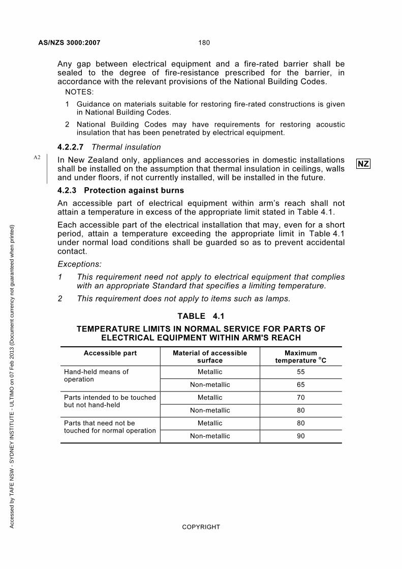
AS/NZS 3000:2007 180
COPYRIGHT
Any gap between electrical equipment and a fire-rated barrier shall be sealed to the degree of fire-resistance prescribed for the barrier, in accordance with the relevant provisions of the National Building Codes.
NOTES:
1 Guidance on materials suitable for restoring fire-rated constructions is given in National Building Codes.
2 National Building Codes may have requirements for restoring acoustic insulation that has been penetrated by electrical equipment.
4.2.2.7 Thermal insulation
In New Zealand only, appliances and accessories in domestic installations shall be installed on the assumption that thermal insulation in ceilings, walls and under floors, if not currently installed, will be installed in the future.
4.2.3 Protection against burns
An accessible part of electrical equipment within arm’s reach shall not attain a temperature in excess of the appropriate limit stated in Table 4.1.
Each accessible part of the electrical installation that may, even for a short period, attain a temperature exceeding the appropriate limit in Table 4.1 under normal load conditions shall be guarded so as to prevent accidental contact.
Exceptions:
1 This requirement need not apply to electrical equipment that complies with an appropriate Standard that specifies a limiting temperature.
2 This requirement does not apply to items such as lamps.
TABLE 4.1
TEMPERATURE LIMITS IN NORMAL SERVICE FOR PARTS OF ELECTRICAL EQUIPMENT WITHIN ARM'S REACH
Accessible part Material of accessible surface
Maximum temperature
oC
Hand-held means of operation
Metallic 55
Non-metallic 65
Parts intended to be touched but not hand-held
Metallic 70
Non-metallic 80
Parts that need not be touched for normal operation
Metallic 80
Non-metallic 90
NZA2
Acc
esse
d by
TA
FE
NS
W -
SY
DN
EY
INS
TIT
UT
E -
ULT
IMO
on
07 F
eb 2
013
(Doc
umen
t cur
renc
y no
t gua
rant
eed
whe
n pr
inte
d)

181 AS/NZS 3000:2007
COPYRIGHT
4.3 CONNECTION OF ELECTRICAL EQUIPMENT
4.3.1 General
Electrical equipment may be connected to the installation wiring by one of the methods detailed in Subclauses 4.3.2 to 4.3.5.
In all cases the point of connection to the installation wiring shall be as close as practicable to the electrical equipment and the connection shall be effectively protected against mechanical damage or interference.
Wiring within, and forming part of, an item of electrical equipment is considered to be equipment wiring. Such wiring shall be in accordance with the relevant product Standard or, where no relevant product standard exists, AS/NZS 3100.
4.3.2 Direct connection
4.3.2.1 General
The installation wiring of the electrical installation shall be directly connected to terminals provided on the electrical equipment for the purpose (see Figure 4.1).
Switchboard
Equipment
Insta l lat ion wir ing
FIGURE 4.1 DIRECT CONNECTION
4.3.2.2 Installation coupler
An installation coupler, enclosed or unenclosed, that meets the requirements of AS/NZS 61535 is a suitable method for the electrical connection of cables, including flexible cords, flexible cables and rigid (solid or stranded) cables.
NOTES:
1 Installation couplers are intended for permanent connection between sections of wiring, particularly in ‘soft’ wiring systems, in which case they are treated in the same manner as a junction box.
2 Installation couplers require a deliberate act to disengage the latching mechanism and are not to be engaged or disconnected under load or to be used as socket-outlets.
Acc
esse
d by
TA
FE
NS
W -
SY
DN
EY
INS
TIT
UT
E -
ULT
IMO
on
07 F
eb 2
013
(Doc
umen
t cur
renc
y no
t gua
rant
eed
whe
n pr
inte
d)

AS/NZS 3000:2007 182
COPYRIGHT
Wiring from an installation coupler to electrical equipment is regarded as installation wiring (see Figure 4.2).
Switchboard
EquipmentInsta l lat ion coupler
Insta l lat ion wir ing
FIGURE 4.2 DIRECT CONNECTION BY INSTALLATION COUPLER
Exception: Where the manufacturer of an item of electrical equipment provides supply terminals for the equipment at a plug designed for connection to an installation coupler, the wiring between the plug and the equipment is regarded as equipment wiring (see Figure 4.3).
Switchboard
Equipment
Insta l lat ion wir ing
Insta l lat ion coupler
Equipment wi r ing
FIGURE 4.3 DIRECT CONNECTION BY INSTALLATION COUPLER-EXCEPTION
4.3.3 Socket-outlet
The installation wiring of the electrical installation shall terminate at a suitable socket-outlet, the wiring to the electrical equipment being continued by means of a plug and flexible cord or cable (see Figure 4.4).
Switchboard
EquipmentSocket-out let and p lug
for connect ion
Insta l lat ion wir ing Equipment wir ing
FIGURE 4.4 CONNECTION BY SOCKET-OUTLET
Acc
esse
d by
TA
FE
NS
W -
SY
DN
EY
INS
TIT
UT
E -
ULT
IMO
on
07 F
eb 2
013
(Doc
umen
t cur
renc
y no
t gua
rant
eed
whe
n pr
inte
d)
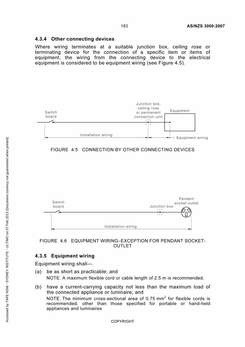
183 AS/NZS 3000:2007
COPYRIGHT
4.3.4 Other connecting devices
Where wiring terminates at a suitable junction box, ceiling rose or terminating device for the connection of a specific item or items of equipment, the wiring from the connecting device to the electrical equipment is considered to be equipment wiring (see Figure 4.5).
Equipment
Junct ion box,ce i l ing rose
or permanentconnect ion un i t
Swi tchboard
Insta l lat ion wir ing Equipment wi r ing
FIGURE 4.5 CONNECTION BY OTHER CONNECTING DEVICES
Pendant socket-out let
Junct ion boxSwitchboard
Insta l lat ion wir ing
FIGURE 4.6 EQUIPMENT WIRING–EXCEPTION FOR PENDANT SOCKET-OUTLET
4.3.5 Equipment wiring
Equipment wiring shall—
(a) be as short as practicable; and
NOTE: A maximum flexible cord or cable length of 2.5 m is recommended.
(b) have a current-carrying capacity not less than the maximum load of the connected appliance or luminaire; and
NOTE: The minimum cross-sectional area of 0.75 mm2 for flexible cords is recommended, other than those specified for portable or hand-held appliances and luminaires
Acc
esse
d by
TA
FE
NS
W -
SY
DN
EY
INS
TIT
UT
E -
ULT
IMO
on
07 F
eb 2
013
(Doc
umen
t cur
renc
y no
t gua
rant
eed
whe
n pr
inte
d)

AS/NZS 3000:2007 184
COPYRIGHT
(c) be protected against short-circuit, in accordance with Clause 2.5.4; and
(d) where earthing is required, be provided with a protective earthing conductor of suitable cross-sectional area that will ensure operation of the circuit protective device, in the event of a fault to earth, without damage to the protective earthing conductor.
Exception:
1 Where an assessment is made of the effect of a fault in the electrical equipment and smaller conductors will meet the protection requirements, conductors with a cross-sectional area of not less than 20% of the rating of the circuit protective device may be used.
2 Wiring between a terminating device and a pendant socket-outlet is considered to be installation wiring (see Clause 3.9.7.4 and Figure 4.6).
4.4 SOCKET-OUTLETS
4.4.1 Types
4.4.1.1 General
Socket-outlets shall be suitable for the intended application and location of installation and shall comply with the requirements of the following Standards or Standards equivalent thereto:
(a) AS/NZS 3112.
(b) AS/NZS 3123.
(c) IEC 60309.
(d) AS/NZS 3131.
4.4.1.2 Different systems
Where an ELV electrical installation and an electrical installation of greater than ELV are in the same premises, all socket-outlets supplied at ELV shall—
(a) have their voltage conspicuously marked; and
(b) be of a form that will prevent insertion of an ELV plug into a socket-outlet connected to a circuit of greater than extra-low voltage.
NOTE: AS/NZS 3112 contains a specific plug and socket-outlet arrangement recommended for ELV applications.
Plugs and socket-outlets for SELV and PELV systems shall not be provided with an earthing contact or pin and shall comply with Clause 7.5.10.
4.4.2 Location
4.4.2.1 Accessibility
Each socket-outlet shall be installed so that any plug intended to be used with the socket-outlet can be conveniently inserted and withdrawn and not cause damage to any flexible cord or cable connected to the plug.
Acc
esse
d by
TA
FE
NS
W -
SY
DN
EY
INS
TIT
UT
E -
ULT
IMO
on
07 F
eb 2
013
(Doc
umen
t cur
renc
y no
t gua
rant
eed
whe
n pr
inte
d)

185 AS/NZS 3000:2007
COPYRIGHT
Socket-outlets shall not be installed where the withdrawal of a plug from the socket-outlet is restricted by a permanent fixture or fitting within the installation.
NOTE: The gas code, the AS/NZS 5601 series, requires that the means of electrical isolation for a gas appliance is accessible with the appliance installed.
4.4.2.2 Protection of socket-outlets
Socket-outlets shall be installed so that they will not be subjected to undue mechanical stress or damage in normal service.
In addition:
(a) Where installed in a floor or other horizontal surface, socket-outlets shall be designed or arranged to prevent the accumulation of dust or water therein.
NOTE: AS/NZS 3112 contains requirements for socket-outlets intended to be mounted in a floor.
(b) Where installed within 75 mm of a floor, socket-outlets shall be installed so that any plug used with the socket-outlet is withdrawn in the horizontal plane.
Exception: This requirement does not apply to a socket-outlet that complies with Items (a) and (d).
(c) Socket-outlets shall be so installed that a plug is not likely to become loose or to malfunction because of gravity, vibration or the weight of the flexible cord or cable.
(d) Where installed in a location that is not readily accessible for the connection of a fixed or stationary appliance or a luminaire, the socket-outlet shall be securely fixed to a structure or support to ensure that no mechanical strain is placed on the installation wiring connections when inserting or removing a plug to the socket-outlet.
Exceptions: The socket-outlet need not be fixed in position where the installation meets the following conditions:
1 Cable connections are not subject to undue mechanical stress on any connection in accordance with Clause 3.7.2.6.
2 The wiring system, where likely to be disturbed, is supported in accordance with Clause 3.9.3.3.
3 The wiring system, where installed in a suspended ceiling, is supported in accordance with Clause 3.9.3.2.
4 Conductors are flexible or stranded type.
5 Insulated, unsheathed cables, including exposed cores where sheathing is removed, are enclosed in accordance with Clause 3.10.1.1.
(e) The use and location of socket-outlets is restricted in a number of particular situations, including damp situations, in accordance with Section 6 and hazardous areas and other situations, in accordance with Section 7.
A2
A2
Acc
esse
d by
TA
FE
NS
W -
SY
DN
EY
INS
TIT
UT
E -
ULT
IMO
on
07 F
eb 2
013
(Doc
umen
t cur
renc
y no
t gua
rant
eed
whe
n pr
inte
d)
AS/NZS 3000:2007 186
COPYRIGHT
Where socket-outlets are installed in building surfaces that are required to provide fire-resistance or acoustic properties, measures shall be taken to ensure that these properties are maintained.
NOTE: Clause 4.2.2.6 and the National Building Codes have requirements for the installation of socket-outlets in building surfaces providing fire-resistance or acoustic properties.
4.4.3 Earthing contacts
Every socket-outlet shall be provided with an earthing contact.
NOTE: See Clause 5.4.2 for earthing requirements.
Exception: In accordance with Clause 7.5.10, socket-outlets for SELV and PELV systems shall not be provided with an earthing contact.
4.4.4 Switching device
4.4.4.1 General
Each socket-outlet shall be individually controlled by a separate switch that complies with either AS/NZS 3133 or AS 60947.3 and operates in all active conductors.
Switches controlling socket-outlets shall comply with Clauses 4.4.4.2 and 4.4.4.3.
Exceptions:
1 A single switch may be used for the control of two socket-outlets located immediately adjacent to each other.
2 A socket-outlet that is rated at not more than 10 A, installed for the connection of a fixed or stationary appliance or a luminaire and that is not readily accessible for other purposes, need not be controlled by a switch.
3 A socket-outlet that is switched by the insertion and withdrawal of the plug shall be deemed to meet the requirements of this Clause.
4.4.4.2 Rating
Each switch shall have a current rating, at its operating voltage, not less than the current rating of the socket-outlet it controls.
Where one switch is used to control two socket-outlets, as permitted by Exception 1 to Clause 4.4.4.1, the current rating of the switch shall be not less than—
(a) the total current rating of the socket-outlets; or
(b) the current rating of the overcurrent protective device on the circuit;
whichever is the lesser value.
4.4.4.3 Location and marking
Each switch, or means of operating the switch, for a socket-outlet shall be—
(a) as close as practicable to the socket-outlet; and
A1
Acc
esse
d by
TA
FE
NS
W -
SY
DN
EY
INS
TIT
UT
E -
ULT
IMO
on
07 F
eb 2
013
(Doc
umen
t cur
renc
y no
t gua
rant
eed
whe
n pr
inte
d)

187 AS/NZS 3000:2007
COPYRIGHT
(b) marked to indicate the socket-outlet(s) or the connected electrical equipment that it controls.
Exception: Marking is not required where the socket-outlet controlled is obvious because of the location of the switch.
Where the switch is located remote from the socket-outlet it shall be—
(i) installed in a convenient and readily accessible position as close as practicable to the socket-outlet; and
(ii) marked in accordance with—
(A) the location of the switch shall be clearly and permanently marked at the socket-outlet; and
(B) both the switch and the socket-outlet shall be provided with legible, indelible and uniform labels indicating their relationship.
Exception: Marking is not required where the socket-outlet is—
(a) located more than 2.5 m above the ground, floor or platform; and
(b) provided for the connection of a specific lamp, luminaire or appliance; and
(c) not accessible for general use.
4.4.4.4 Pendant-type socket-outlet
A switch incorporated in a pendant socket-outlet attached to a flexible cord shall interrupt all live (active and neutral) conductors.
Exception: Pendant-type multiphase outlets with switching only in the active conductors may be used where—
(a) the outlet is not dependent on the supply cable for support; and
(b) additional mechanical protection is provided where necessary; and
(c) the supply cable or cord is selected to take into account any likelihood of vibration and movement expected during operation.
4.4.5 Polarization and phase sequence
Where socket-outlets of the same type form part of an electrical installation, the order of connection of the socket-outlets shall be the same.
All socket-outlets that accommodate three-pin/flat-pin plugs shall be connected so that, when viewed from the front of the socket-outlet, the order of connection commencing from the slot on the radial line shall be earth, active, neutral in a clockwise direction.
4.5 LIGHTING EQUIPMENT AND ACCESSORIES
4.5.1 Lampholders
4.5.1.1 Location
All lampholders shall be located to be adequately protected against damage that might reasonably be expected.
Acc
esse
d by
TA
FE
NS
W -
SY
DN
EY
INS
TIT
UT
E -
ULT
IMO
on
07 F
eb 2
013
(Doc
umen
t cur
renc
y no
t gua
rant
eed
whe
n pr
inte
d)

AS/NZS 3000:2007 188
COPYRIGHT
In order to protect against inadvertent contact with live parts, low voltage lampholders shall be located to minimize the risk of—
(a) direct contact with live parts of a lampholder when the lamp is removed; and
(b) mechanical damage to the lamp or lampholder.
These requirements may be satisfied by—
(i) installation not less than 1.8 m above the ground, floor or platform, or
(ii) provision of a suitable guard for the lamp and its lampholder, or
(iii) the lampholder is incorporated in a luminaire.
NOTE: A pendant lampholder should not be exposed to the effects of significant movement of air, e.g. outdoors or where exposed to the operation of fans, etc.
4.5.1.2 Edison screw lampholders
Every low voltage edison screw lampholder shall be connected to the supply so that, where a neutral conductor is required, it shall be connected to the outer contact.
Exception: This requirement need not apply where an Edison screw lampholder is incorporated in an appliance in a manner permitted by the AS/NZS 60335 series or the AS/NZS 3350 series or the luminaire and the lampholder is provided with a shroud or skirt that prevents contact with the outer contact.
4.5.1.3 Festoon lighting
Festoon lighting shall be located and supported so that no lamp will be within—
(a) 0.15 m of flammable materials or structural metalwork; or
(b) arm’s reach of the ground or any other place on which a person is likely to stand.
Exception: Festoon lighting may be within arm’s reach where installed immediately below a ceiling.
4.5.2 Lamps and luminaires
4.5.2.1 General
Lamps, luminaires and their associated ancillary gear shall be so installed as not to cause undue temperature rise, ignition or deterioration of the materials—
(a) on which they are mounted; or
(b) that they illuminate.
Luminaires shall—
(i) be suitable for the highest temperatures to which they are likely to be subjected by external influences; and
(ii) be installed in accordance with the manufacturer’s instructions, taking account of the highest rating of lamp to be used.
A1
Acc
esse
d by
TA
FE
NS
W -
SY
DN
EY
INS
TIT
UT
E -
ULT
IMO
on
07 F
eb 2
013
(Doc
umen
t cur
renc
y no
t gua
rant
eed
whe
n pr
inte
d)

189 AS/NZS 3000:2007
COPYRIGHT
NOTES:
1 Some building materials can be affected by pyrolysis—the decomposition of organic material as a result of long-term exposure to elevated temperatures. Where exposed to high temperatures for a significant period of time, such materials can self-ignite.
2 Attention is drawn to the high temperatures that can be generated in luminaires. Cables with suitable insulation temperature ratings should be selected.
4.5.2.2 Lamps near flammable materials
Where lamps are located near flammable materials—
(a) lamps shall be suitably shielded by a shade, reflector, guard or enclosure to prevent contact with the material; and
(b) lamps, such as spotlights, that generate heat in the illuminated surface, shall be separated by such a distance that the material will not attain excessive temperature.
Where information is not otherwise provided with products, the minimum separation distances given in Table 4.2 shall be used.
Flammable shades shall not be installed where they are liable to come in contact with any lamp.
TABLE 4.2
MINIMUM DISTANCE BETWEEN LAMP AND ILLUMINATED FLAMMABLE MATERIALS
Rating (W)
Minimum distance (m)
≤ 100 0.6
> 100 ≤ 300 1.0
> 300 1.8
4.5.2.3 Recessed luminaires
4.5.2.3.1 Requirements
Recessed luminaires and their auxiliary equipment shall be installed in a manner designed to prevent—
(a) excessive temperature rise of the luminaire and auxiliary equipment; and
(b) the risk of fire from ignition of combustible materials.
These requirements shall be satisfied by one of the following compliance methods:
(i) The installation of a luminaire designed and certified by the manufacturer as being suitable for operation—
(A) in contact with combustible materials; or
A2
A2
Acc
esse
d by
TA
FE
NS
W -
SY
DN
EY
INS
TIT
UT
E -
ULT
IMO
on
07 F
eb 2
013
(Doc
umen
t cur
renc
y no
t gua
rant
eed
whe
n pr
inte
d)

AS/NZS 3000:2007 190
COPYRIGHT
(B) in contact with or enclosed/covered by thermal insulation material.
(ii) The installation of a luminaire in combination with a barrier tested and classified in compliance with AS/NZS 5110 as being suitable for the installation conditions.
(iii) The installation of a luminaire with separation from thermal insulating materials, combustible building elements and loose combustible materials not less than—
(A) the minimum clearance specified by the manufacturer of the luminaire, which may require a barrier or guard constructed of fire-resistant materials; or
(B) the default clearances as specified in Figure 4.7, which may require a barrier or guard constructed of fire-resistant materials.
Recessed luminaire
Combustib le bui lding e lement above f i t t ingCombustib le bui lding e lement above f i t t ing
Thermalinsulat ionThermal
insulat ionThermal
insulat ion
C
A
B
Auxi l iar yequipment
Combustib le bui lding e lementFixed guard required where - • insulat ion mater ia ls are not secured in posit ion• loose mater ia ls are present (See 4.5.2.3.3(e) and (f ) )
D
Dimension Clearance
A – Clearance above luminaire 200 mm
B – Side clearance to combustible building element 200 mm
C – Side clearance to bulk thermal insulation 50 mm
D – Clearance to auxiliary equipment (transformer for example)
50 mm
FIGURE 4.7 DEFAULT MINIMUM CLEARANCES FOR RECESSED LUMINAIRES
4.5.2.3.2 Warning sign
Where recessed luminaires are installed in an accessible roof space, a permanent and legible warning sign shall be installed in the roof space adjacent to the access panel, in a position that is visible to a person entering the space. The sign shall comply with AS 1319 and contain the words shown in Figure 4.8 with a minimum size of lettering of 10 mm.
A2
Acc
esse
d by
TA
FE
NS
W -
SY
DN
EY
INS
TIT
UT
E -
ULT
IMO
on
07 F
eb 2
013
(Doc
umen
t cur
renc
y no
t gua
rant
eed
whe
n pr
inte
d)

191 AS/NZS 3000:2007
COPYRIGHT
WARNINGWARNING
Recessed lights have been installed in this roof space. To reduce the r isk of f ire DO NOT COVER the light f i t t ings
with thermal insulation or any other material unless in
accordance with instructions provided by the light f i t t ing or
barrier manufacturer.
FIGURE 4.8 WARNING SIGN TO BE INSTALLED IN ACCESSIBLE ROOF SPACES CONTAINING RECESSED LUMINAIRES
4.5.2.3.3 Installation precautions
The following precautions should be undertaken for the installation of recessed downlights:
(a) The heat generated from lamps should be dissipated in order to prevent over-temperature damage to the luminaire or to adjacent materials. Cooling air circulation through or around the equipment is a requirement for the typical range of downlights. AS/NZS 60598.1 and AS/NZS 60598.2.2 detail the test method and the maximum surface temperatures permitted for recessed luminaires. The maximum temperature of adjacent materials is to be no more than 90°C.
(b) In the case of a suitably designed and certified luminaire (compliance method 4.5.2.3.1(i)), the manufacturer’s instructions may restrict installation including warnings such as covering with insulation or the following AS/NZS 60598.1 symbol meaning ‘Do Not Cover’.
However, for typical fittings, the installation method will be to provide barriers (compliance method 4.5.2.3.1(ii)) or clearances (compliance method 4.5.2.3.1(iii)) during installation, so as to prevent contact with materials that may impede air flow (e.g. thermal insulation) or that may be affected by the high temperature (e.g. combustible building elements).
A2
Acc
esse
d by
TA
FE
NS
W -
SY
DN
EY
INS
TIT
UT
E -
ULT
IMO
on
07 F
eb 2
013
(Doc
umen
t cur
renc
y no
t gua
rant
eed
whe
n pr
inte
d)

AS/NZS 3000:2007 192
COPYRIGHT
Unmarked light fittings shall be treated as ‘Do Not Cover’.
(c) Under National Building Code requirements, bulk thermal insulation is prevalent in modern building construction within roofs, ceilings, walls and floors depending on the type of building and its climate zone.
Bulk thermal insulation may also be retrofitted, added or altered in which case precautions will need to be applied by the insulation installer, where recessed downlights are present, or the luminaire installer, where insulation is present.
In Australia AS 3999 and in New Zealand NZS 4246 include instructions for insulation installers in relation to clearances from recessed downlights and other types of electrical equipment that may be adversely affected by lack of cooling air circulation.
(d) The presence of bulk thermal insulation, particularly over the rear of a ceiling mounted downlight, can readily impair cooling air circulation. Unless the luminaire manufacturer specifies otherwise (compliance method 4.5.2.3.1(i)) or the barrier is classified to permit insulation coverage (compliance method 4.5.2.3.1(ii)), the space above the luminaire, shown as dimension A of Figure 4.7, shall remain clear and a warning sign as shown in Figure 4.8 shall be installed.
(e) Where clearances are to be applied (compliance method 4.5.2.3.1(iii)) and bulk thermal insulation is not fixed in position, one of the following means shall be provided and secured in position to maintain the clearances:
(i) A barrier complying with AS/NZS 5110.
(ii) A guard complying with AS 3999.
(iii) A barrier or guard constructed of fire-resistant materials.
(f) Combustible materials should be prevented from being in close proximity or contacting hot surfaces of the luminaires. This includes structural timber which may be affected by pyrolysis which over a long exposure can result in increased susceptibility to ignition.
Where extraneous material, such as leaves, vermin debris or combustible materials stored in a roof space, are present in proximity to the downlight, the precautions shall include the use of a suitably designed and certified luminaire (compliance method 4.5.2.3.1(i)) or a barrier (compliance method 4.5.2.3.1(ii)).
(g) Unless the auxiliary equipment instructions permit otherwise, any auxiliary equipment operating at a high temperature shall be installed above any insulation as illustrated in Figure 4.7.
A2
Acc
esse
d by
TA
FE
NS
W -
SY
DN
EY
INS
TIT
UT
E -
ULT
IMO
on
07 F
eb 2
013
(Doc
umen
t cur
renc
y no
t gua
rant
eed
whe
n pr
inte
d)

193 AS/NZS 3000:2007
COPYRIGHT
4.5.2.3.4 Additional installation requirements—New Zealand only
The following additional requirements apply in New Zealand only:
(a) Only recessed luminaires of Classes IC-F, IC, CA80 or CA135, which are compliant with AS/NZS 60598.2.2, including NZ only Amendment A, shall be installed in residential buildings. (See Clause 4.5.2.3.1(i).)
(b) If the recessed luminaire is supplied with a detachable barrier, the complete luminaire, including its barrier, shall be installed.
(c) All classes of recessed luminaire shall be spaced from other building elements as given in the luminaire manufacturer’s installation instructions. If no instructions are available, the default clearances shown in Figure 4.9 shall apply and a fixed guard constructed of rigid fire-resistant material may be required.
NZA2
Acc
esse
d by
TA
FE
NS
W -
SY
DN
EY
INS
TIT
UT
E -
ULT
IMO
on
07 F
eb 2
013
(Doc
umen
t cur
renc
y no
t gua
rant
eed
whe
n pr
inte
d)
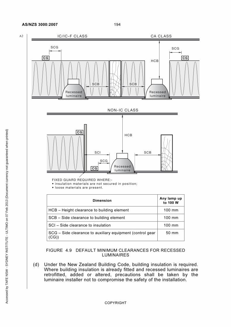
AS/NZS 3000:2007 194
COPYRIGHT
CG CG
CG
CG
HCB
IC/IC-F CLASS
NON-IC CLASS
CA CLASS
HCB
SCG SCG
SCB
SCBSCB
SCI
SCG
FIXED GUARD REQUIRED WHERE:-• insulat ion mater ia ls are not secured in posit ion;• loose mater ia ls are present.
SCBSCB
Recessedluminaire
Recessedluminaire
Recessedluminaire
Dimension Any lamp up
to 100 W
HCB – Height clearance to building element 100 mm
SCB – Side clearance to building element 100 mm
SCI – Side clearance to insulation 100 mm
SCG – Side clearance to auxiliary equipment (control gear (CG))
50 mm
FIGURE 4.9 DEFAULT MINIMUM CLEARANCES FOR RECESSED LUMINAIRES
(d) Under the New Zealand Building Code, building insulation is required. Where building insulation is already fitted and recessed luminaires are retrofitted, added or altered, precautions shall be taken by the luminaire installer not to compromise the safety of the installation.
A2
Acc
esse
d by
TA
FE
NS
W -
SY
DN
EY
INS
TIT
UT
E -
ULT
IMO
on
07 F
eb 2
013
(Doc
umen
t cur
renc
y no
t gua
rant
eed
whe
n pr
inte
d)

195 AS/NZS 3000:2007
COPYRIGHT
(e) For recessed luminaires with lamps of wattage higher than 100 W only compliance methods 4.5.2.3.1(i) or 4.5.2.3.1(iii)A, may be used.
NOTE: Additional information may be obtained from AS/NZS 60598.2.2 including NZ only Amendment A and NZS 4246.
4.5.2.4 Suspended ceilings
Luminaires that are supported by a ceiling panel shall not—
(a) present a mechanical loading that exceeds the capacity of the ceiling panel; and
(b) operate at a temperature that would cause deformation, discolouration or other forms of deterioration of the ceiling panel.
NOTE: AS/NZS 2785 requires that rigid infill panels or independent supports may be required for some panels. Refer to manufacturer’s information for limitations on particular ceiling systems.
4.6 SMOKE AND FIRE DETECTORS
National Building Codes have requirements for installation of fire and smoke detectors in domestic residences, including location and number required.
Where mains powered smoke or fire detectors are fitted such detectors may be directly connected to the lighting final subcircuit or to an individual final subcircuit.
NOTES:
1 Use of the lighting final subcircuit provides monitoring that the mains power supply is available, as failure of lighting in an electrical installation would be indicated by the non-operation of lighting luminaires.
2 Fire and smoke detectors are not considered to be safety services for the purposes of this Standard.
4.7 COOKING APPLIANCES
4.7.1 Switching device
A circuit for a fixed or stationary cooking appliance having an open cooking surface incorporating electric heating, e.g. cooktop, deep fat fryer, barbecue griddle or similar, shall be provided with a switch, operating in all active conductors, mounted near the appliance in a visible and readily accessible position.
Switches shall be marked to identify the appliance controlled.
Where the open cooking surface is a combined gas/electric appliance incorporating both gas and electric cooking, the switching device shall operate in all live (active and neutral) conductors.
Exception: Where an electric cooktop is installed in a public park or other open area, the required switch may be installed adjacent to the cooktop and, to prevent damage by vandalism, may be placed under a lockable cover that is located so that it is able to be operated as required for servicing and maintenance purposes of the cooktop.
A2
A2
Acc
esse
d by
TA
FE
NS
W -
SY
DN
EY
INS
TIT
UT
E -
ULT
IMO
on
07 F
eb 2
013
(Doc
umen
t cur
renc
y no
t gua
rant
eed
whe
n pr
inte
d)

AS/NZS 3000:2007 196
COPYRIGHT
NOTES:
1 The switch should be mounted within two metres of the cooking appliance, but not on the cooking appliance, in such a position that the user does not have to reach across the open cooking surface.
2 A single switch is permissible for the control of associated cooking appliances in the same room.
3 It is recommended that switches, particularly those in domestic installations, be marked to identify the appliance controlled.
4 This requirement is not intended to apply to enclosed cooking appliances, such as built-in ovens and microwave ovens.
4.7.2 Connection
In New Zealand, a freestanding cooking appliance shall be connected to the electrical installation wiring by a socket-outlet or an installation coupler.
NOTE: This requirement need not apply to built-in hobs and ovens.
4.8 APPLIANCES PRODUCING HOT WATER OR STEAM
4.8.1 General
All appliances producing hot water or steam shall be protected against overheating, by design or installation, in all service conditions.
Protection shall be provided by means of an appropriate non-self-resetting device, functioning independently of the thermostat.
Exception: This requirement need not apply to appliances that comply as a whole with an appropriate Standard.
Where an appliance has no free outlet, it shall also be provided with a device that limits the water pressure.
4.8.2 Water heaters
4.8.2.1 Access to easing equipment of pressure-relief and terminals of protective devices
Every unvented water heater shall be installed so that the following are readily available for operation, inspection and adjustment:
(a) Easing equipment of pressure-relief devices.
(b) All terminals of the protective devices.
NOTE: An unvented water heater is one that is intended to operate at the pressure of the water system and the flow of the water being controlled by one or more valves in the outlet system.
4.8.2.2 Protective devices fitted to unvented water heaters
Overtemperature cut-outs and similar protective devices fitted to unvented water heaters shall—
(a) operate directly in the circuit wiring to the heater elements; and
(b) not be arranged for control through relays or contactors.
NZ
Acc
esse
d by
TA
FE
NS
W -
SY
DN
EY
INS
TIT
UT
E -
ULT
IMO
on
07 F
eb 2
013
(Doc
umen
t cur
renc
y no
t gua
rant
eed
whe
n pr
inte
d)

197 AS/NZS 3000:2007
COPYRIGHT
4.8.2.3 Isolating switch
Every water heater shall be provided with an independent isolating switch or switches in accordance with Clause 2.3.2.2. Such switch or switches shall be—
(a) additional to any automatic switch incorporated in the heater structure; and
(b) grouped together; and
(c) installed on or adjacent to the water heater, or on the switchboard at which the water heater final subcircuit originates.
4.9 ROOM HEATERS
4.9.1 General
Where a permanently connected room heater, or a number of permanently connected room heaters, are installed in one room, an individual isolating switch and an individual functional switch shall be provided for each room heater or for each group of room heaters.
Where a number of permanently connected room heaters are installed in one room and are supplied by the one final subcircuit, a single isolating switch may be used for the room heaters in that room.
4.9.2 Isolating switches
In accordance with Clause 2.3.2.2, isolating switches shall be—
(a) installed immediately adjacent to an entrance to, or within, the room where the room heater is located; or
(b) installed on the switchboard at which the room heater final subcircuit originates.
Isolating switches may be incorporated in temperature-control devices, provided that they have a definite ‘OFF’ position.
4.9.3 Functional switches
In accordance with Clause 2.3.7, functional switches shall be installed in a readily accessible position in the same room, or immediately adjacent to an entrance to the room, in which the room heater or room heaters are located.
A functional switch may be—
(a) an appliance switch or switches with an ‘OFF’ position incorporated within the room heater; or
(b) an isolating switch provided in accordance with Clause 4.9.2(a).
4.10 ELECTRIC HEATING CABLES FOR FLOORS AND CEILINGS AND TRACE HEATING APPLICATIONS
4.10.1 General
Cables for electric heating systems in floors and ceilings and trace heating applications shall be of a type specifically designed for the
Acc
esse
d by
TA
FE
NS
W -
SY
DN
EY
INS
TIT
UT
E -
ULT
IMO
on
07 F
eb 2
013
(Doc
umen
t cur
renc
y no
t gua
rant
eed
whe
n pr
inte
d)

AS/NZS 3000:2007 198
COPYRIGHT
purpose. The heating equipment shall be installed in accordance with the manufacturer’s instructions.
NOTE: In New Zealand, additional requirements for underfloor and ceiling heating cables are detailed in NZS 6110.
4.10.2 Heating cables
Heating cables shall be so installed that they—
(a) are not in contact with flammable materials; and
(b) where designed to be embedded—
(i) are completely and adequately embedded in the substance they are intended to heat; and
(ii) do not suffer any detrimental effect because of flexing or movement of the substance in which they are embedded; or
(c) where designed as trace heating cables, shall provide adequate heat transfer to the surface or material to which they are fixed.
4.10.3 Isolating switches
Cables, or groups of cables, that comprise the heating system shall be provided with an isolating switch or switches in accordance with Clause 2.3.2.2.
Isolating switches may be incorporated in temperature-control devices, provided that they have a definite ‘OFF’ position.
Isolating switches shall be—
(a) installed immediately adjacent to an entrance to, or within, the room or area in which the heating system is located; or
(b) installed on the switchboard at which the heating system final sub-circuit originates.
Exception: Where the heating system is provided for trace heating applications, the isolating switch need not be located as specified in this Clause.
4.10.4 Functional switches
Cables or groups of cables that comprise the heating system shall be provided with a functional switch or switches, in accordance with Clause 2.3.7.
Functional switches shall be installed in a readily accessible position immediately adjacent to an entrance to, or within, the room or area in which the heating system is located.
A functional switch may be an isolating switch in accordance with Clause 4.10.3(a).
Exception: Where the heating system is provided for trace heating applications, the functional switch need not be located as specified in this Clause.
NZ
Acc
esse
d by
TA
FE
NS
W -
SY
DN
EY
INS
TIT
UT
E -
ULT
IMO
on
07 F
eb 2
013
(Doc
umen
t cur
renc
y no
t gua
rant
eed
whe
n pr
inte
d)
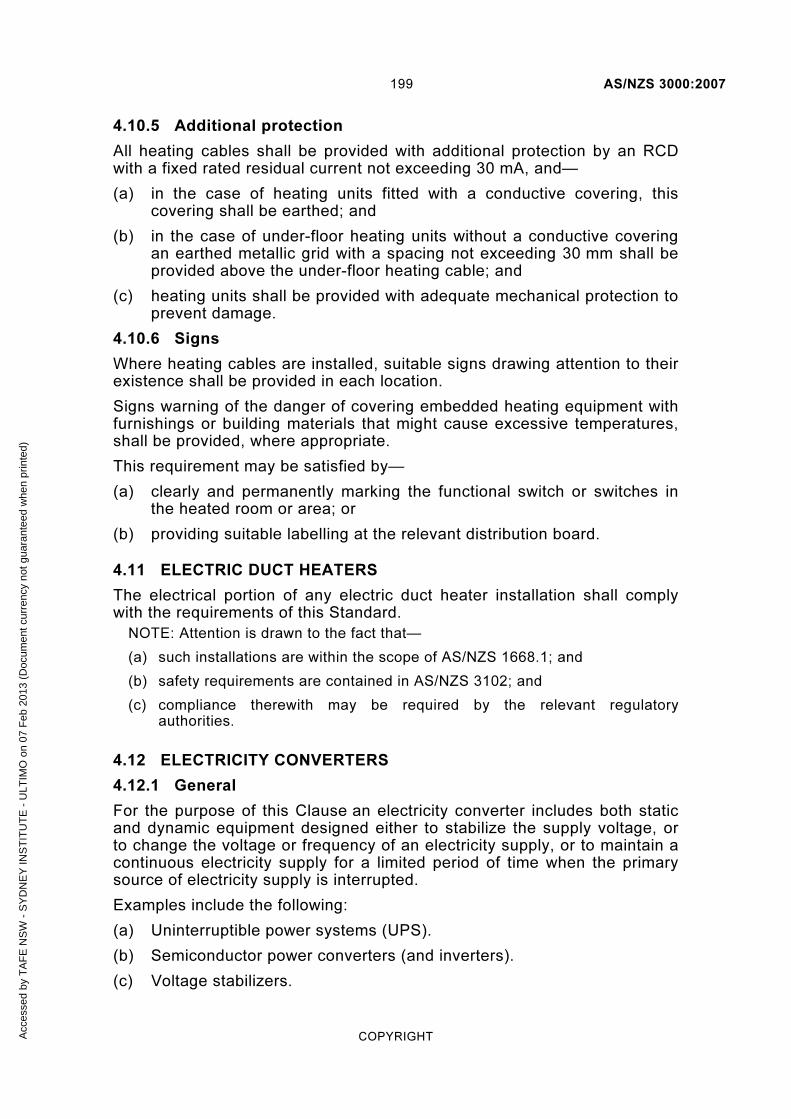
199 AS/NZS 3000:2007
COPYRIGHT
4.10.5 Additional protection
All heating cables shall be provided with additional protection by an RCD with a fixed rated residual current not exceeding 30 mA, and—
(a) in the case of heating units fitted with a conductive covering, this covering shall be earthed; and
(b) in the case of under-floor heating units without a conductive covering an earthed metallic grid with a spacing not exceeding 30 mm shall be provided above the under-floor heating cable; and
(c) heating units shall be provided with adequate mechanical protection to prevent damage.
4.10.6 Signs
Where heating cables are installed, suitable signs drawing attention to their existence shall be provided in each location.
Signs warning of the danger of covering embedded heating equipment with furnishings or building materials that might cause excessive temperatures, shall be provided, where appropriate.
This requirement may be satisfied by—
(a) clearly and permanently marking the functional switch or switches in the heated room or area; or
(b) providing suitable labelling at the relevant distribution board.
4.11 ELECTRIC DUCT HEATERS
The electrical portion of any electric duct heater installation shall comply with the requirements of this Standard.
NOTE: Attention is drawn to the fact that—
(a) such installations are within the scope of AS/NZS 1668.1; and
(b) safety requirements are contained in AS/NZS 3102; and
(c) compliance therewith may be required by the relevant regulatory authorities.
4.12 ELECTRICITY CONVERTERS
4.12.1 General
For the purpose of this Clause an electricity converter includes both static and dynamic equipment designed either to stabilize the supply voltage, or to change the voltage or frequency of an electricity supply, or to maintain a continuous electricity supply for a limited period of time when the primary source of electricity supply is interrupted.
Examples include the following:
(a) Uninterruptible power systems (UPS).
(b) Semiconductor power converters (and inverters).
(c) Voltage stabilizers.
Acc
esse
d by
TA
FE
NS
W -
SY
DN
EY
INS
TIT
UT
E -
ULT
IMO
on
07 F
eb 2
013
(Doc
umen
t cur
renc
y no
t gua
rant
eed
whe
n pr
inte
d)

AS/NZS 3000:2007 200
COPYRIGHT
(d) Motor-generator sets.
(e) Rotary converters.
Transformers and engine-driven generating sets that comply with AS/NZS 3010 shall not be considered as electricity converters.
NOTE: Requirements for alternative, stand-by and stand-alone systems are set out in Clause 7.3.
4.12.2 Selection and installation
Guidance on the selection and installation of electricity converters is contained in—
(a) for uninterruptible power systems (UPS) ... AS/NZS 62040 series; and
(b) for semiconductor power converters ......... AS 60146 series; and
(c) for batteries ............................................. AS 3011; and
(d) for rotating electrical machines ................. AS1359 series.
4.12.3 Control
Where an electrical installation, or part thereof, is supplied through an electricity converter, the converted supply shall be controlled by an isolating switch, or switches, at the output of the converter, or at the switchboard to which the output is connected.
Each electricity converter shall be controlled by switches or devices suitable for starting and stopping the converter. Where there is more than one switch or device for this purpose, they shall be grouped together and clearly identified.
An electricity converter shall be so arranged that it cannot supply energy upstream of the point of connection to the installation either directly or indirectly.
Exception: Electricity converters may be arranged to supply energy upstream of the point of connection to the installation subject to any additional conditions required by the electricity distributor.
Provision shall be made to ensure that all necessary connections for protection in the installation remain intact when supply is available from the output of the electricity converter.
4.12.4 Isolation
4.12.4.1 General
Each electricity converter shall be provided with an independent isolating switch in accordance with Clause 2.3.2.2 that shall—
(a) be installed adjacent to or on the electricity converter so that a person operating the switch has a clear view of any person working on the converter; and
(b) comply with Clause 4.13 when the electricity converter incorporates an electric motor; and
(c) be under manual control only; and
Acc
esse
d by
TA
FE
NS
W -
SY
DN
EY
INS
TIT
UT
E -
ULT
IMO
on
07 F
eb 2
013
(Doc
umen
t cur
renc
y no
t gua
rant
eed
whe
n pr
inte
d)

201 AS/NZS 3000:2007
COPYRIGHT
(d) not be capable of being overridden or bypassed by programmable control systems or the like.
4.12.4.2 Electricity converters incorporating batteries
Where batteries are incorporated in an electricity converter, a switch capable of interrupting the supply from such batteries shall be installed adjacent to the isolating switch (see Clause 4.12.4.1) and shall be clearly identified to indicate its purpose.
Exception: A single switch that incorporates both a.c. and d.c. switching functions outlined in Clause 4.12.4.1 and this Clause 4.12.4.2 may be used.
4.12.5 Overcurrent protection
4.12.5.1 Electricity converter protection
Electricity converters shall be provided with overcurrent protection.
Exception: Overcurrent protective devices shall not be provided where the unexpected interruption of the supply could cause a greater danger than overcurrent.
Overcurrent protective devices shall be located as close as practicable to the output terminals of the electricity converter so that the unprotected interconnecting conductors are as short as practicable and, in no case, exceed 15 m in length.
The unprotected interconnecting conductors shall be completely enclosed by metal or other material that is not flammable.
Exception: Overcurrent protection may be provided by—
(a) an overcurrent protective device within the electricity converter itself; or
(b) the characteristics of the electricity converter being unable to support the fault current.
Where an electricity converter is intended to operate in parallel with a network or other source, circulating harmonic currents shall be limited so that the current-carrying capacity of conductors is not exceeded.
NOTE: The effects of circulating harmonic currents may be limited as follows:
(a) The selection of generating sets with compensated windings.
(b) The provision of a suitable impedance in the connection to generator star points.
(c) The provision of switches that interrupt the circulatory circuit but that are interlocked so that at all times fault protection is not impaired.
(d) The provision of filtering equipment.
(e) Other suitable means.
Acc
esse
d by
TA
FE
NS
W -
SY
DN
EY
INS
TIT
UT
E -
ULT
IMO
on
07 F
eb 2
013
(Doc
umen
t cur
renc
y no
t gua
rant
eed
whe
n pr
inte
d)

AS/NZS 3000:2007 202
COPYRIGHT
4.12.5.2 Circuit protection
(a) General Every submain or final subcircuit outgoing from an electricity converter shall be individually protected in accordance with Clause 2.5 and shall also include additional protection, where required, by Clause 2.6.
Exceptions:
1 This requirement need not apply where protection on the incoming side (if any) provides protection against an overcurrent condition on the outgoing side.
2 Overcurrent protective devices shall not be provided where the unexpected interruption of the supply could cause a greater danger than overcurrent.
(b) RCDs The possible waveform of a fault current to earth can affect the operation of RCDs and shall be taken into account for the selection of the type of RCD.
Where an electricity converter includes an inverter, the RCD shall be of a type suitable for the waveform of the particular inverter, and in accordance with the inverter manufacturer’s recommendations.
NOTE: Requirements for types of RCDs are set out in Clause 2.6.2.2.
4.12.6 Earthing
The output of an electricity converter shall be provided with the same type of earthing system used for the associated electrical installation.
Protective earthing conductors shall not be switched.
Provision shall be made to ensure that all necessary connections for protection, such as the MEN connection, remain intact when supply is available from the output of the system.
NOTE: See Clause 4.12.2 for information regarding Standards applicable to various devices.
4.12.7 Neutral continuity
Electricity converters, particularly static converters, such as UPS, shall be arranged to ensure that the continuity of the neutral conductor to the load is not interrupted during bypass or maintenance switching.
4.12.8 Electrical equipment connected to output
All electrical equipment connected to the output side of an electricity converter shall be suitable for the voltage, current and frequency of the output of the unit.
NOTES:
1 The values of current-carrying capacity and voltage drop specified in the AS/NZS 3008.1 series are valid only for conductors operating at 50 Hz.
2 Refer to Clause 2.6.2.2 regarding the type of RCD to be used where additional protection is required for circuits or equipment supplied by an electricity converter.
Acc
esse
d by
TA
FE
NS
W -
SY
DN
EY
INS
TIT
UT
E -
ULT
IMO
on
07 F
eb 2
013
(Doc
umen
t cur
renc
y no
t gua
rant
eed
whe
n pr
inte
d)

203 AS/NZS 3000:2007
COPYRIGHT
4.13 MOTORS
4.13.1 Protection against injury from mechanical movement
4.13.1.1 Switching devices
Every motor shall be provided with a switching device capable of performing the following functions—
(a) starting and stopping the motor; and
(b) emergency stopping, in accordance with Clause 2.3.5; and
(c) isolating the motor for mechanical maintenance, in accordance with Clause 2.3.6.
Exceptions:
1 Where a number of motors are required to function as a group, or operate in a coordinated manner, e.g. a split system airconditioning unit, a single switching device may be used to control more than one motor.
2 A switch suitable for disconnection of supply in accordance with Item (c) need not be provided for motors that are—
(i) connected by a plug and socket-outlet; or
(ii) incorporated in an appliance having no exposed moving parts; or
(iii) rated at not greater than 150 VA.
NOTES:
1 Refer to Clause 2.3 for the location and function of the switching device.
2 AS/NZS 1668.1 requires provision for locking air-handling and smoke-spill motor-isolating switches in the ON position.
4.13.1.2 Rating of switches
The isolating switch shall have a rating of not less than—
(a) the full-load current of the motor when installed directly in the motor-supply circuit; or
(b) the control-circuit current when installed in the motor-starter circuit.
Any switch operating directly in the motor-supply circuit shall be capable of safely interrupting the locked-rotor or stall current of the motor. In the absence of any specific information supplied by the manufacturer, the locked-rotor or stall current shall be taken as—
(i) eight times the full-load current for a.c. motors; or
(ii) four times the full-load current for d.c. motors.
NOTE: Switches suitable for this application include the following:
(a) Switches complying with AS 3133, marked with the letter ‘M’ and with the nominated locked-rotor current.
(b) Switches complying with AS/NZS 3947.3, marked with the utilization category ‘DC 23’ or ‘AC 23’ and with a rated operational current which is equal to or greater than the full-load current of the motor.
Acc
esse
d by
TA
FE
NS
W -
SY
DN
EY
INS
TIT
UT
E -
ULT
IMO
on
07 F
eb 2
013
(Doc
umen
t cur
renc
y no
t gua
rant
eed
whe
n pr
inte
d)

AS/NZS 3000:2007 204
COPYRIGHT
(c) Switches incorporated with and supplying a socket-outlet intended for use with a plug complying with AS/NZS 3112.
Where one switch is used to isolate more than one motor, in accordance with Clause 4.13.1.1, the switch shall be capable of interrupting the sum of the following currents:
(A) The locked-rotor or stall current of the largest motor in the group.
(B) The full-load current of all other motors in the group.
4.13.1.3 Devices for starting and stopping
Starting-and-stopping devices shall be so located as to be easily operated by the person in charge of the motor.
A stopping device or isolating switch shall be provided where danger is likely to occur because of the presence of moving parts.
The stopping device shall remain effective in the event of a fault in a motor-control circuit.
Where electrical equipment is remotely controlled devices shall be provided for stopping the motors at all points where danger is likely to occur.
Arrangements for emergency stopping of motors shall comply with Clause 2.3.5.
4.13.1.4 Protection against restarting or reversal
Where unexpected restarting of a motor might cause danger, each electric motor shall be provided with means to prevent automatic restarting after stopping.
NOTE: Such means need not be provided where a suitable method of avoiding danger by warning of automatic restarting is given. Alternatives include enclosure of moving parts, warning sirens, etc.
Where safety might be impaired by incorrect direction of rotation of a motor, suitable measure shall be taken to prevent danger from reversal of the direction of rotation.
NOTE: This applies particularly where reverse-current braking is used.
4.13.2 Protection against overload
Each electric motor having a rating exceeding 370 W shall be provided with control equipment incorporating means of protection against overload of the motor.
Exception: This Clause does not apply to motors incorporated in an item of electrical equipment that complies with an appropriate Standard.
A2
Acc
esse
d by
TA
FE
NS
W -
SY
DN
EY
INS
TIT
UT
E -
ULT
IMO
on
07 F
eb 2
013
(Doc
umen
t cur
renc
y no
t gua
rant
eed
whe
n pr
inte
d)

205 AS/NZS 3000:2007
COPYRIGHT
4.13.3 Protection against overtemperature
4.13.3.1 General
Electric motors shall be provided with overtemperature protective devices complying with Clause 4.13.3.3 where they—
(a) may be required to run unattended (see Note) and have a rating greater than—
(i) for shaded-pole type motors ....... 480 VA; or
(ii) for other unattended motors ....... 240 VA
(b) have a rating greater than 2250 W.
Exception: This Clause does not apply where overtemperature protection is not permitted or required in accordance with Clause 4.13.3.2.
NOTE: A continuously running motor or a motor under automatic control in non-domestic premises, where no person is normally in attendance in the vicinity of the motor, is deemed to be unattended. Consideration should be given to the presence of a caretaker, or other person who may be responsible for the inspection of motors, in which case it may be appropriate not to regard motors as unattended. Examples of unattended motors are motors that—
(a) operate refrigerators in shops; or
(b) are in a remote portion of a building, such as a drainage sump in a basement; or
(c) operate a communal refrigerator in a block of flats.
4.13.3.2 Protection not required
Overtemperature protection shall not be provided where—
(a) in accordance with Clause 7.2.9, protection shall not be provided for motors associated with a fire-protection service; or
(b) the opening of the motor circuit could create a hazard.
Overtemperature protection need not be provided for unattended submersible pump motors immersed in water that have a rating not greater than 2250 W.
4.13.3.3 Overtemperature protective devices
Overtemperature protective devices shall comply with the following:
(a) Protection Protection of motor windings against excessive temperatures shall be provided by—
(i) thermal overload protective devices complying with AS 60947.4.1; or
(ii) built-in thermal protection, in accordance with AS 60947.8; or
(iii) a device that affords an equivalent degree of protection.
(b) Operation The protective device shall disconnect, directly or indirectly, not less than the following number of supply conductors to the motor:
A1
Acc
esse
d by
TA
FE
NS
W -
SY
DN
EY
INS
TIT
UT
E -
ULT
IMO
on
07 F
eb 2
013
(Doc
umen
t cur
renc
y no
t gua
rant
eed
whe
n pr
inte
d)

AS/NZS 3000:2007 206
COPYRIGHT
(i) For single-phase a.c. motors and d.c. motors supplied from a two-wire supply with one line earthed and single-phase a.c. motors, one.
(ii) For three-phase a.c. motors and d.c. motors supplied from two unearthed lines, two.
(c) Additional requirements for unattended motors Where thermal protective devices for unattended motors are of the automatic reset type, the device shall protect the motor windings against attaining excessive temperatures under continued tripping conditions.
4.14 TRANSFORMERS
4.14.1 General
Transformers shall be installed in accordance with Clauses 4.14.2 to 4.14.5.
Exception: The following transformers need not comply with this Clause:
(a) An instrument transformer.
(b) An extra-low voltage transformer.
(c) A luminous discharge tube transformer.
(d) A transformer incorporated in a motor starter or other similar electrical equipment.
4.14.2 Secondary circuit
4.14.2.1 General
The wiring and electrical equipment connected to the secondary winding of a transformer shall comply with the requirements of this Standard for extra-low, low or high voltage, as appropriate to the nominal secondary voltage.
4.14.2.2 Control and protection
The conductors connected to the secondary windings of a transformer shall be—
(a) considered as submain or final subcircuit conductors, as appropriate; and
(b) controlled and protected in accordance with the appropriate requirements of Clauses 2.3 and 2.5.
Exception: This requirement need not apply where—
(a) the transformer secondary winding supplies only one submain or final subcircuit; and
(b) the secondary circuit conductors have a current-carrying capacity not less than the rated load current of the transformer primary winding multiplied by the ratio of the transformer primary voltage to the secondary voltage.
Acc
esse
d by
TA
FE
NS
W -
SY
DN
EY
INS
TIT
UT
E -
ULT
IMO
on
07 F
eb 2
013
(Doc
umen
t cur
renc
y no
t gua
rant
eed
whe
n pr
inte
d)

207 AS/NZS 3000:2007
COPYRIGHT
4.14.3 Low voltage transformer supply
4.14.3.1 Isolating transformers
Electrical equipment may be supplied through an isolating transformer, in accordance with Clause 7.4.
4.14.3.2 Other transformers
Electrical equipment shall be earthed as required by Clause 5.4.
Exception: Where the low voltage transformer output complies with the requirements of the AS/NZS 61558 series, earthing is not required on the secondary side.
4.14.4 Autotransformers
An autotransformer shall not be used to supply electrical equipment, including circuit wiring, having a voltage rating of less than the highest input or output voltage of the autotransformer.
4.14.5 Step-up transformers
Where a transformer is used to raise the voltage above that at which electricity is supplied at the point of supply, no connection shall be made between the primary and secondary windings.
Exception: A connection may be made between primary and secondary windings, using a protective earthing conductor, to provide an earth-reference supply.
4.15 CAPACITORS
4.15.1 General
Capacitors shall be installed in accordance with Clauses 4.15.2 and 4.15.3.
Exception: The requirements of this Standard do not apply to capacitors that are fitted as an integral part of other electrical equipment, such as luminaires.
4.15.2 Electrical equipment
4.15.2.1 General
Electrical equipment and wiring for connection to capacitors shall be suitable for the highest voltages, currents and temperatures that are likely to occur.
Adequate means shall be provided to ensure the dissipation of heat from the electrical equipment.
4.15.2.2 Rating of circuit-breakers, switches, or contactors
Any circuit-breaker, switch or contactor controlling a capacitor shall be suitable for the purpose of switching capacitors and shall be of appropriate rating for the reactive component.
An example of an appropriate contactor would be a utilisation category AC-6b device to the AS60947.4.1.
Acc
esse
d by
TA
FE
NS
W -
SY
DN
EY
INS
TIT
UT
E -
ULT
IMO
on
07 F
eb 2
013
(Doc
umen
t cur
renc
y no
t gua
rant
eed
whe
n pr
inte
d)

AS/NZS 3000:2007 208
COPYRIGHT
4.15.2.3 Current-carrying capacity of supply conductors
Where a capacitor is controlled by a circuit-breaker as required by Clause 4.15.3.3(a), the conductors connected to the capacitor shall have a current-carrying capacity not less than the greater of—
(a) 135% of the rated current of the capacitor; or
(b) the setting of the circuit-breaker.
Where a capacitor is permanently connected to a motor circuit, the conductors shall have a current rating of not less than the greater of—
(i) one-third of the rating of the motor-circuit conductors; or
(ii) 135% of the rated current of the capacitor.
4.15.3 Provision for discharge and control
4.15.3.1 General
Capacitors with values greater than 0.5 µF shall be provided with a discharge path.
These capacitors shall be controlled in accordance with one of the methods set out in Clauses 4.15.3.2 and 4.15.3.3, as appropriate.
The voltage between capacitor terminals shall be not more than 50 V after the capacitor has been disconnected from the supply for the following period, as applicable:
(a) Where the capacitor is rated up to and including 650 V ............. 1 min.
(b) Where the capacitor is rated above 650 V ................................. 5 min.
Capacitors and electrical equipment containing capacitors shall be provided with a warning notice containing information similar to the following:
WARNING: ENSURE THAT CAPACITORS ARE COMPLETELY
DISCHARGED BEFORE WORKING ON EQUIPMENT
4.15.3.2 Capacitors connected in parallel with individual appliances
A capacitor connected in parallel with an individual appliance shall comply with the following requirements:
(a) The capacitor shall be connected so that the windings of the appliance form a permanent discharge path for the capacitor.
(b) No switch or fuse shall be inserted between the capacitor and the appliance.
Exception: The requirements of (a) and (b) need not apply where the capacitor incorporates a permanently connected discharge device.
(c) The capacitor shall be deemed to be controlled by the controlgear of the appliance.
4.15.3.3 Capacitors not connected in parallel with individual appliances
A capacitor not connected in parallel with an individual appliance shall comply with the following requirements:
A2
Acc
esse
d by
TA
FE
NS
W -
SY
DN
EY
INS
TIT
UT
E -
ULT
IMO
on
07 F
eb 2
013
(Doc
umen
t cur
renc
y no
t gua
rant
eed
whe
n pr
inte
d)

209 AS/NZS 3000:2007
COPYRIGHT
(a) The capacitor shall be controlled by a circuit-breaker fitted with an overcurrent release.
Provision shall be made for the discharge of the capacitor by the use of—
(i) auxiliary contacts of the circuit-breaker that automatically connect a discharge device to the capacitor immediately it is disconnected from the supply; or
(ii) a permanently connected discharge device in parallel with the capacitor.
Exception: Where either—
(A) the capacitor is rated at not more than 100 kVAr; or
(B) each capacitor in a bank of shunt-connected capacitors is rated at not more than 100 kVAr—
the capacitor may be controlled by a quick make-and-break switch or contactor and protected by fuses, provided that—
(1) such switching shall incorporate a means of manual operation to provide for the individual isolation of each capacitor, or for the capacitor bank as a whole; and
(2) provision shall be made for the discharge of the capacitor by the use of a permanently connected discharge device in parallel with the capacitor.
(b) No fuse or switch shall be connected between—
(i) the auxiliary contacts of the circuit-breaker and the discharge device referred to in Item (a)(i); or
(ii) the permanently connected discharge device and a capacitor referred to in Item (a)(ii).
4.16 ELECTRICAL EQUIPMENT CONTAINING LIQUID DIELECTRICS
4.16.1 General
Wherever electrical equipment, such as oil-filled transformers or capacitors, contains flammable liquid in significant quantity, precautions shall be taken to prevent burning liquid and the products of combustion of the liquid (flame, smoke, toxic gases) spreading to other parts of the premises.
4.16.2 Liquid dielectrics having a flashpoint not exceeding 250°C
Where electrical equipment is filled with a liquid dielectric having a flashpoint not exceeding 250°C and has a total liquid capacity exceeding 50 L in any unit or group of adjacent units, precautions shall be taken to prevent the spread of fire.
Such precautions may include the provision of enclosures consisting of fire-resisting dykes, bunds, curbed areas, basins, trenches filled with coarse crushed stone or, where necessary, trapped drains.
Acc
esse
d by
TA
FE
NS
W -
SY
DN
EY
INS
TIT
UT
E -
ULT
IMO
on
07 F
eb 2
013
(Doc
umen
t cur
renc
y no
t gua
rant
eed
whe
n pr
inte
d)

AS/NZS 3000:2007 210
COPYRIGHT
NOTES:
1 Examples of such precautions are—
(a) a drainage pit to collect leakages of liquid and ensure their extinction in the event of fire; or
(b) installation of the electrical equipment in a chamber of adequate fire-resistance and the provision of sills or other means of preventing burning liquid spreading to other parts of the premises, such chamber being ventilated solely to the external atmosphere.
2 For less than 50 L, it is generally sufficient to take precautions to prevent the escape of liquid.
3 It may be desirable to switch off the supply to the electrical equipment automatically at the onset of a fire.
4.17 BATTERIES
Information on the selection and installation of batteries is contained in AS 3011.1 and AS 3011.2.
4.18 GAS APPLIANCES
4.18.1 General
A gas appliance connected to the electricity supply shall be provided with a means of electrical isolation that is adjacent to the appliance location and is accessible with the appliance in the installed position.
The means of isolation shall be—
(a) a plug to a switched socket-outlet; or
(b) a plug to a socket-outlet that may be located in an inaccessible position but has a separate switch operating in all live (active and neutral) conductors located in an accessible position; or
(c) a switch operating in all live (active and neutral) conductors.
NOTE: If the appliance has an open cooking surface incorporating both gas and electric cooking, it shall also comply with Clause 4.7.
4.18.2 Gas cylinders containing heavier-than-air gases—outdoors
Electrical equipment that is a source of ignition, such as socket-outlets, switches, luminaires, switchboards, meter boxes and airconditioners, shall not be installed within the hazardous areas shown in Figure 4.10 by dimensions A and B. Dimensions A and B are shown in Figure 4.10 for both exchange and in-situ fill gas cylinders. For further information, refer to AS/NZS 60079.10.1 and AS/NZS 5601 particularly for gases lighter than air.
Exception: Approved combined gas and electrical meter enclosures are exempted from these requirements.
NOTE: Electrical equipment selected and installed in accordance with Clause 7.7.2.4 is not considered an ignition source.
A2
Acc
esse
d by
TA
FE
NS
W -
SY
DN
EY
INS
TIT
UT
E -
ULT
IMO
on
07 F
eb 2
013
(Doc
umen
t cur
renc
y no
t gua
rant
eed
whe
n pr
inte
d)

211 AS/NZS 3000:2007
COPYRIGHT
A
500*
* This distance is measured f rom the top of any cyl inder va lve.
B
Ground level
A 500 1500
Exchange cyl inder(mm)
In-s i tu f i l l cyl inder(mm)
B 1500 3500
FIGURE 4.10 HAZARDOUS AREA PRESENTED BY A GAS CYLINDER OUTDOORS FOR HEAVIER-THAN-AIR GASES
NOTE: For further information, refer to AS/NZS 60079.10.1 and AS/NZS 5601, particularly for gases lighter than air.
4.18.3 Reticulated lighter-than-air gas system, metering system and regulators
In New Zealand only, electrical equipment, excepting those items that are part of the gas system and installed to the hazardous area requirements, shall not be installed within the hazardous areas shown in Figure 4.11 for both venting and non-venting regulators. For additional information refer to AS/NZS 5601.
Exception: The dimensions may be reduced where the owner of the metering or pressure reducing equipment has otherwise advised a different zoning either in writing or by way of a sign or sticker attached permanently in proximity to the gas equipment.
NOTE: Electrical equipment selected and installed in accordance with Clause 7.7.2.4 is not considered an ignition source.
NZ
A2
Acc
esse
d by
TA
FE
NS
W -
SY
DN
EY
INS
TIT
UT
E -
ULT
IMO
on
07 F
eb 2
013
(Doc
umen
t cur
renc
y no
t gua
rant
eed
whe
n pr
inte
d)

AS/NZS 3000:2007 212
COPYRIGHT
R 800 mmR 800 mmR 800 mmR 800 mm
GMS cover
Service valve
Service r iser
Finishedground level
1600 mm1600 mm
800 mm
1600 mm
Exclusion ZoneThis indicates the s ize of the exclusion zone.I t star ts at ground level and is centred on the service r iser.
FIGURE 4.11 HAZARDOUS AREA FOR RETICULATED GAS SUPPLY REGULATORS
4.19 AIRCONDITIONING AND HEAT PUMP SYSTEMS
Airconditioning and heat pump systems incorporating a compressor shall be provided with a lockable isolating switch installed adjacent to the unit, which isolates all parts of the system including ancillary equipment, from the same location.
For split system airconditioning units, where the manufacturer requires the airconditioning system to be connected to the electricity supply by means of a plug and socket at the internal unit, the isolating switch installed at the external unit shall control the socket-outlet located at the internal unit.
Exception: The isolating switch may be installed at the switchboard supplying the system if the switchboard is dedicated to the equipment (e.g. an airconditioning plant room).
NZ
A2
Acc
esse
d by
TA
FE
NS
W -
SY
DN
EY
INS
TIT
UT
E -
ULT
IMO
on
07 F
eb 2
013
(Doc
umen
t cur
renc
y no
t gua
rant
eed
whe
n pr
inte
d)

213 AS/NZS 3000:2007
COPYRIGHT
S E C T I O N 5 E A R T H I N G A R R A N G E M E N T S
A N D E A R T H I N G C O N D U C T O R S
5.1 GENERAL
5.1.1 Application
The provisions of Section 5 form the minimum standard in relation to the selection and installation of earthing arrangements that must be achieved to satisfy the requirements of Part 1 of this Standard.
5.1.2 Selection and installation
Earthing arrangements shall be selected and installed to perform the following functions, or have the following features, associated with the proper design, construction and safe operation of the electrical installation:
(a) Enable automatic disconnection of supply in the event of a short-circuit to earth fault or excessive earth leakage current in the protected part of the installation through protective earthing arrangements.
(b) Enable equipment requiring an earth reference to function correctly through functional earth (FE) arrangements.
(c) Mitigate voltage differences appearing between exposed conductive parts of equipment and extraneous conductive parts through equipotential bonding arrangements.
(d) Provide an effective and reliable low impedance fault path capable of carrying earth fault and earth leakage currents without danger or failure from thermal, electromechanical, mechanical, environmental and other external influences.
(e) Provide measures for the connection of exposed conductive parts and extraneous conductive parts.
5.1.3 MEN earthing system
The protective earthing arrangements required in this Standard apply to electrical installations connected to the multiple earthed neutral (MEN) distribution system that forms the standard distribution system used in Australia and New Zealand.
Under the MEN system the neutral conductor of the distribution system is earthed at the source of supply, at regular intervals throughout the system and at each electrical installation connected to the system. Within the electrical installation, the earthing system is separated from the neutral conductor and is arranged for the connection of the exposed conductive parts of equipment.
The MEN system and its various parts are illustrated in Figures 5.1 and 5.2.
NOTE: IEC 60364 describes the MEN system as a TN-C-S system with the letters signifying—
Acc
esse
d by
TA
FE
NS
W -
SY
DN
EY
INS
TIT
UT
E -
ULT
IMO
on
07 F
eb 2
013
(Doc
umen
t cur
renc
y no
t gua
rant
eed
whe
n pr
inte
d)

AS/NZS 3000:2007 214
COPYRIGHT
T the distribution system is directly connected to earth—at the neutral point of the supply transformer
N the exposed conductive parts are connected to the earthed point of the distribution system—at the MEN connection
C the neutral and protective conductor functions are combined in a single conductor (the neutral conductor of the distribution system)
S the protective conductor function is separated from the neutral—separate conductors within the installation.
Acc
esse
d by
TA
FE
NS
W -
SY
DN
EY
INS
TIT
UT
E -
ULT
IMO
on
07 F
eb 2
013
(Doc
umen
t cur
renc
y no
t gua
rant
eed
whe
n pr
inte
d)
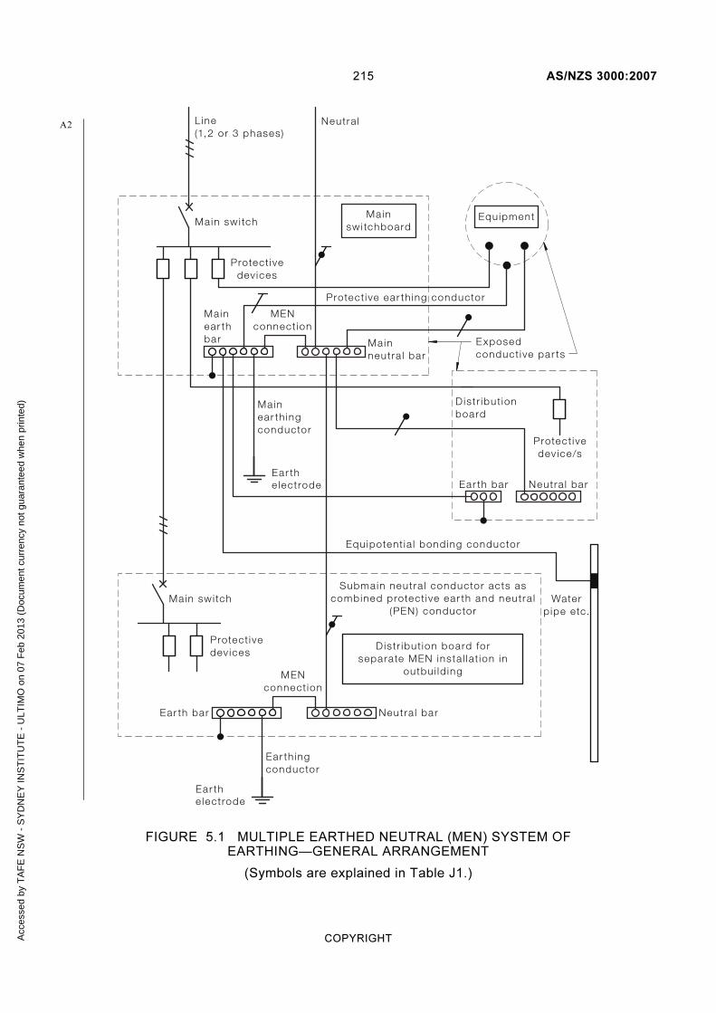
215 AS/NZS 3000:2007
COPYRIGHT
Ear the lectrode
Mainswi tchboard
Protect ivedev ices
Neutra lL ine(1,2 or 3 phases)
Main swi tch
Mainear thbar
Mainear th ingconductor
Ear th ingconductor
Mainneutra l bar
Equipment
MENconnect ion
Protect ive ear th ing conductor
Ear th bar Neutra l bar
Ear the lectrode
Main swi tch
Protect ivedev ices
Submain neutra l conductor acts ascombined protect ive ear th and neutra l
(PEN) conductor
Equipotent ia l bonding conductor
Waterp ipe etc.
D istr ibut ion board forseparate MEN insta l lat ion in
outbui ld ing
Ear th bar Neutra l bar
Protect ivedev ice/s
Distr ibut ionboard
MENconnect ion
Exposedconduct ive par ts
FIGURE 5.1 MULTIPLE EARTHED NEUTRAL (MEN) SYSTEM OF EARTHING—GENERAL ARRANGEMENT
(Symbols are explained in Table J1.)
A2
Acc
esse
d by
TA
FE
NS
W -
SY
DN
EY
INS
TIT
UT
E -
ULT
IMO
on
07 F
eb 2
013
(Doc
umen
t cur
renc
y no
t gua
rant
eed
whe
n pr
inte
d)
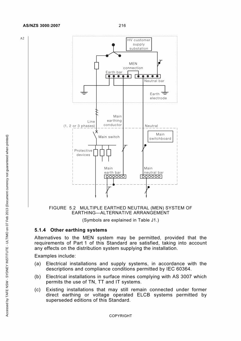
AS/NZS 3000:2007 216
COPYRIGHT
HV customersupply
substat ion
Ear the lectrode
Mainswi tchboard
Protect ivedev ices
Mainear th ing
conductor Neutra lL ine
(1, 2 or 3 phases)
Ear th bar
Neutra l bar
Main swi tch
Mainear th bar
Mainneutra l bar
MENconnect ion
FIGURE 5.2 MULTIPLE EARTHED NEUTRAL (MEN) SYSTEM OF EARTHING—ALTERNATIVE ARRANGEMENT
(Symbols are explained in Table J1.)
5.1.4 Other earthing systems
Alternatives to the MEN system may be permitted, provided that the requirements of Part 1 of this Standard are satisfied, taking into account any effects on the distribution system supplying the installation.
Examples include:
(a) Electrical installations and supply systems, in accordance with the descriptions and compliance conditions permitted by IEC 60364.
(b) Electrical installations in surface mines complying with AS 3007 which permits the use of TN, TT and IT systems.
(c) Existing installations that may still remain connected under former direct earthing or voltage operated ELCB systems permitted by superseded editions of this Standard.
A2
Acc
esse
d by
TA
FE
NS
W -
SY
DN
EY
INS
TIT
UT
E -
ULT
IMO
on
07 F
eb 2
013
(Doc
umen
t cur
renc
y no
t gua
rant
eed
whe
n pr
inte
d)

217 AS/NZS 3000:2007
COPYRIGHT
(d) Earthing/bonding arrangements for installations that are not supplied from a distribution system.
5.2 EARTHING FUNCTIONS
5.2.1 Protective earthing
When a fault occurs between a live part and an exposed conductive part or parts of the protective earthing system, a prospective touch voltage may arise between simultaneously accessible conductive parts. Fault protection by means of automatic disconnection of supply is intended to limit this voltage.
Automatic disconnection is achieved by—
(a) the provision of a protective earthing system in which exposed conductive parts are connected via conductors or similar medium to the earthed neutral of the distribution system; and
(b) in the event of a fault current or excessive earth leakage current flowing in the protective earthing system, overcurrent or earth leakage current protective devices operate to disconnect the affected part of the installation within the specified time and touch voltage limits.
5.2.2 Functional earthing (FE)
Equipment may be required, to be connected to the earthing system for purposes of correct operation rather than the safety conditions associated with protective earthing. In such cases functional earthing conductors are not required to be selected and installed to withstand fault currents or to be identified in the same manner as a protective earthing conductor.
Examples include:
(a) Functional earth (FE) connections fitted to certain types of RCDs to provide an earth for an alternative supply connection for the internal electronic circuit operation in the event of the incoming neutral connection becoming disconnected.
(b) Conductors connecting cathodic protection systems or radio interference suppression devices to a separate earthing arrangement.
(c) Where a ‘clean earth’ is specified for data or signalling purposes in a particular item of electrical equipment, the manufacturer of the electrical equipment should be consulted in order to confirm the necessary arrangements.
Where required, for operational purposes, functional earth connections for data and signalling purposes should be insulated from all protective earthing connections and conductors and should only be connected together at one point, normally at the connection to the main earthing terminal/connection or bar. Care must be exercised to avoid unintentional contact between the two earthing systems.
No conductor insulation colour for functional earth conductors has been detailed in this standard. To ensure that functional earthing connections are made to the correct earthing system a green or green/yellow conductor identification should not be used.
Acc
esse
d by
TA
FE
NS
W -
SY
DN
EY
INS
TIT
UT
E -
ULT
IMO
on
07 F
eb 2
013
(Doc
umen
t cur
renc
y no
t gua
rant
eed
whe
n pr
inte
d)

AS/NZS 3000:2007 218
COPYRIGHT
In Australia, for telecommunication system earthing, see AS/ACIF S009 for the requirements for the colour and installation of a Telecommunications Reference Conductor.
NOTE: Further additional information on functional earthing is available in IEC 60364-4-44.
5.2.3 For combined protective and functional purposes
Where earthing for combined protective and functional purposes is required, the requirements for protective purposes shall prevail.
5.3 EARTHING SYSTEM PARTS
5.3.1 General
The protective earthing arrangement for an electrical installation providing protection by means of automatic disconnection of supply and connected to the MEN system of distribution shall include the following parts:
(a) Protective earthing conductors connecting exposed conductive parts as required.
(b) Main earthing conductor.
(c) Main earthing terminal, connection or bar.
(d) MEN connection between the main earthing terminal, connection or bar and the supply neutral bar.
(e) Earth electrode.
(f) Equipotential bonding of extraneous conductive and other parts as required.
NOTE: Examples of the parts of the MEN system of earthing are shown in Figures 5.1 and 5.2.
The parts of the earthing system shall comply with Clauses 5.3.2 to 5.3.7.
5.3.2 Earthing conductor material and type
5.3.2.1 Conductor material
5.3.2.1.1 Copper conductors
Copper earthing conductors shall be of high conductivity copper and shall be in the form of—
(a) stranded conductors; or
(b) circular braided conductors; or
(c) solid conductors having a cross-sectional area not less than 10 mm2 and a thickness not less than 1.5 mm.
Exceptions:
1 A smaller solid conductor may be used where permitted by a particular cable standard.
2 This Clause need not apply where copper cable components, such as sheaths or screens, are deemed to be an earthing conductor in accordance with Clause 5.3.2.2.
A
Acc
esse
d by
TA
FE
NS
W -
SY
DN
EY
INS
TIT
UT
E -
ULT
IMO
on
07 F
eb 2
013
(Doc
umen
t cur
renc
y no
t gua
rant
eed
whe
n pr
inte
d)
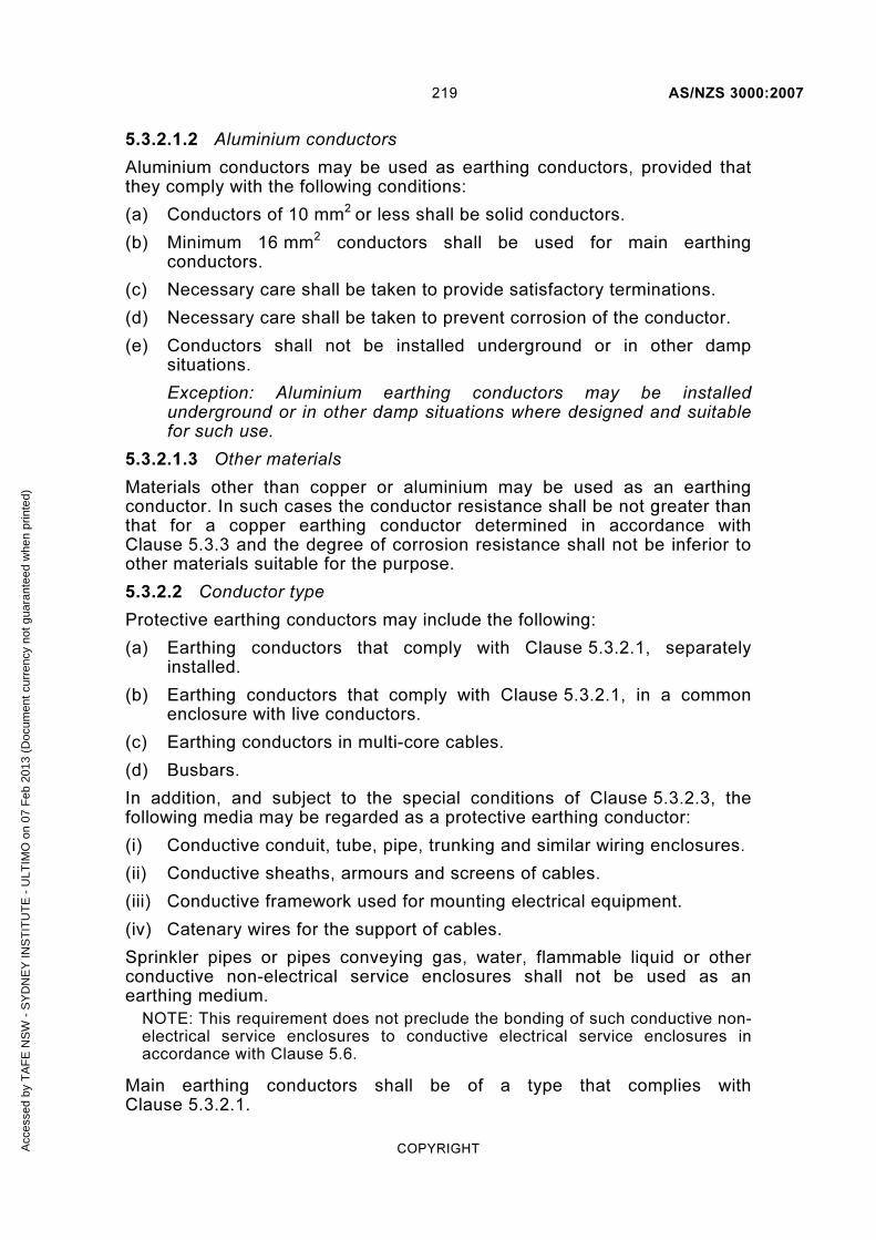
219 AS/NZS 3000:2007
COPYRIGHT
5.3.2.1.2 Aluminium conductors
Aluminium conductors may be used as earthing conductors, provided that they comply with the following conditions:
(a) Conductors of 10 mm2 or less shall be solid conductors.
(b) Minimum 16 mm2 conductors shall be used for main earthing conductors.
(c) Necessary care shall be taken to provide satisfactory terminations.
(d) Necessary care shall be taken to prevent corrosion of the conductor.
(e) Conductors shall not be installed underground or in other damp situations.
Exception: Aluminium earthing conductors may be installed underground or in other damp situations where designed and suitable for such use.
5.3.2.1.3 Other materials
Materials other than copper or aluminium may be used as an earthing conductor. In such cases the conductor resistance shall be not greater than that for a copper earthing conductor determined in accordance with Clause 5.3.3 and the degree of corrosion resistance shall not be inferior to other materials suitable for the purpose.
5.3.2.2 Conductor type
Protective earthing conductors may include the following:
(a) Earthing conductors that comply with Clause 5.3.2.1, separately installed.
(b) Earthing conductors that comply with Clause 5.3.2.1, in a common enclosure with live conductors.
(c) Earthing conductors in multi-core cables.
(d) Busbars.
In addition, and subject to the special conditions of Clause 5.3.2.3, the following media may be regarded as a protective earthing conductor:
(i) Conductive conduit, tube, pipe, trunking and similar wiring enclosures.
(ii) Conductive sheaths, armours and screens of cables.
(iii) Conductive framework used for mounting electrical equipment.
(iv) Catenary wires for the support of cables.
Sprinkler pipes or pipes conveying gas, water, flammable liquid or other conductive non-electrical service enclosures shall not be used as an earthing medium.
NOTE: This requirement does not preclude the bonding of such conductive non-electrical service enclosures to conductive electrical service enclosures in accordance with Clause 5.6.
Main earthing conductors shall be of a type that complies with Clause 5.3.2.1.
Acc
esse
d by
TA
FE
NS
W -
SY
DN
EY
INS
TIT
UT
E -
ULT
IMO
on
07 F
eb 2
013
(Doc
umen
t cur
renc
y no
t gua
rant
eed
whe
n pr
inte
d)

AS/NZS 3000:2007 220
COPYRIGHT
5.3.2.3 Special conditions
The following conditions apply where the components in Clause 5.3.2.2 (i), (ii), (iii) or (iv) are used for protective earthing:
(a) Conductive conduit, tube, pipe, trunking and similar wiring enclosures Conductive conduit, tube, pipe, trunking and similar wiring enclosures may be regarded as a protective earthing conductor, provided that—
(i) the electrical equipment to be earthed is supplied by live conductors contained within the wiring enclosure; and
(ii) for screwed conductive wiring enclosures, the wiring enclosure is directly connected by conductive threads or locknuts to the electrical equipment to be earthed.
(b) Conductive sheaths, armours and screens of cables Conductive sheaths, armours and screens of cables may be regarded as a protective earthing conductor, provided that the electrical equipment to be earthed is supplied only by live conductors incorporated in the cable.
Exception: This requirement shall not preclude the use of a MIMS cable sheath as a main earthing conductor, provided that any circuit-protective earthing conductors connected to the sheath are associated only with the circuits supplied through the MIMS cable.
(c) Conductive framework
(i) General Conductive framework may be regarded as a protective earthing conductor, provided that—
(A) the exposed conductive parts of electrical equipment are mounted on, and in effective electrical contact with, the framework; and
(B) the conductive framework is earthed by the connection of a protective earthing conductor directly to the framework.
(ii) Contact with hinged components Hinged components of conductive framework, such as cubicle doors, may be regarded as a protective earthing conductor, provided that—
(A) the fixed component of the framework is connected to a protective earthing conductor; and
(B) the fixed and hinged components of the framework are connected by means of a flexible protective earthing conductor.
(iii) Contact with moving components The interface between moving components may be regarded as a protective earthing conductor, provided that—
(A) the fixed component of the equipment is directly connected to a protective earthing conductor; and
Acc
esse
d by
TA
FE
NS
W -
SY
DN
EY
INS
TIT
UT
E -
ULT
IMO
on
07 F
eb 2
013
(Doc
umen
t cur
renc
y no
t gua
rant
eed
whe
n pr
inte
d)

221 AS/NZS 3000:2007
COPYRIGHT
(B) the fixed and movable components of the equipment are in effective contact by means of metal-to-metal bearing surfaces, such as the contact between a rail and wheel or between an axle and bearing.
Additional means of electrical continuity, such as sliding shoes or spring-loaded brushes, may be required where an accumulation of rust or non-conductive dust is likely to occur.
(d) Catenary wires A catenary wire may be regarded as a protective earthing conductor, provided that it—
(i) has not less than seven strands; and
(ii) is supported by means of suitable anchorages; and
(iii) has a nominal cross-sectional area of not less than 8.5mm2 if constructed of hard-drawn copper or galvanized low carbon (mild) steel; and
(iv) has a resistance in accordance with the requirements of Clause 5.3.3; and
(v) is identified as an earthing conductor, in accordance with Clause 3.8.3.4, for aerial earthing conductors at each anchorage point or catenary support.
5.3.2.4 Insulation
Earthing conductors shall be provided with insulation.
Exception: The following forms of earthing conductors need not be provided with insulation:
(a) Aerial conductors.
(b) Flat braided conductors.
(c) Busbars.
(d) Sheaths of MIMS cable.
(e) Conductive framework and wiring enclosures deemed to be an earthing conductor, in accordance with Clause 5.3.2.2.
(f) Copper earthing conductors buried direct in the ground in accordance with Clause 5.5.5.5.
(g) Catenary wires.
5.3.2.5 Identification
Insulated earthing conductors shall be identified in accordance with Clause 3.8.
Acc
esse
d by
TA
FE
NS
W -
SY
DN
EY
INS
TIT
UT
E -
ULT
IMO
on
07 F
eb 2
013
(Doc
umen
t cur
renc
y no
t gua
rant
eed
whe
n pr
inte
d)

AS/NZS 3000:2007 222
COPYRIGHT
5.3.3 Earthing conductor size (cross-sectional area)
5.3.3.1 Protective earthing conductors
5.3.3.1.1 General
The cross-sectional area of a protective earthing conductor shall ensure—
(a) adequate current-carrying capacity for prospective fault currents for a time at least equal to the operating time of the associated overcurrent protective device; and
(b) appropriate earth fault-loop impedance (see Clause 5.7); and
(c) adequate mechanical strength and resistance to external influences; and
(d) for parts of the protective earthing conductor that do not consist of cables, or parts of cables, that there is allowance for subsequent deterioration in conductivity that may reasonably be expected.
5.3.3.1.2 Selection
The cross-sectional area of any copper protective earthing conductor required for the protection of any portion of an electrical installation shall be determined either—
(a) from Table 5.1 in relation to the cross-sectional area of the largest active conductor supplying the portion of the electrical installation to be protected; or
(b) by calculation, in accordance with Clause 5.3.3.1.3.
Exceptions:
1 The minimum size of a conductor required for the earthing of exposed conductive parts associated with unprotected consumers mains shall be in accordance with Clauses 5.3.3.2 and 5.5.3.5 .
2 Aerial earthing conductors shall comply with Clause 5.3.3.3.
3 Earthing conductors in cables, flexible cables or flexible cords shall comply with Clause 5.3.3.4.
NOTES:
1 The installation should be so prepared that electrical equipment terminals are capable of accepting the protective earthing conductors.
2 Calculation may be necessary if the choice of cross-sectional area of phase conductors has been determined by consideration of short-circuit current.
Where the active conductor comprises a number of conductors, connected in parallel, the earthing conductor shall be determined in relation to the summation of the cross-sectional areas of the individual conductors forming the largest active conductor to be protected.
Acc
esse
d by
TA
FE
NS
W -
SY
DN
EY
INS
TIT
UT
E -
ULT
IMO
on
07 F
eb 2
013
(Doc
umen
t cur
renc
y no
t gua
rant
eed
whe
n pr
inte
d)

223 AS/NZS 3000:2007
COPYRIGHT
Where the summation of cross-sectional areas does not correspond exactly with the nominal size of the active conductor given in Table 5.1, the conductor shall be determined in relation to the nearest larger size of active conductor.
The minimum cross-sectional area of any conductive wiring enclosure, cable component, framework or catenary wire used as an earthing medium in accordance with Clause 5.3.2.2, shall be such that the impedance of the medium is not greater than that determined for a copper earthing conductor in accordance with this Clause 5.3.3.1.2.
5.3.3.1.3 Calculation
The minimum cross-sectional area determined by calculation shall be not less than the value determined by the following equation (applicable only for disconnection times not less than 0.1 s but not exceeding 5 s).
( )22KtIS /= 5.1
where
S = cross-sectional area of protective earthing conductor, in mm2
I = the value of the fault current in amperes (for a.c. r.m.s. value) that would flow through the overcurrent protective device of the circuit concerned in the event of a short-circuit of negligible impedance
t = the disconnecting time of the overcurrent protective device in seconds, corresponding to the value of fault current I
K = factor dependent on the material of the protective earthing conductor, the insulation and other parts and the initial and the final temperatures
NOTES:
1 Values of K for protective earthing conductors in various conditions of service are given in the AS/NZS 3008.1 series, e.g. for copper conductors not laid up with other conductors, with PVC insulation K = 136, or for bare copper conductors K = 170.
2 Examples of the application of this equation are contained in the AS/NZS 3008.1 series.
If application of the equation produces non-standard sizes, conductors of the nearest higher standard cross-sectional area shall be used.
NOTE: Maximum permissible temperatures for joints should be considered (see the AS/NZS 3008.1 series).
A1
Acc
esse
d by
TA
FE
NS
W -
SY
DN
EY
INS
TIT
UT
E -
ULT
IMO
on
07 F
eb 2
013
(Doc
umen
t cur
renc
y no
t gua
rant
eed
whe
n pr
inte
d)

AS/NZS 3000:2007 224
COPYRIGHT
TABLE 5.1
MINIMUM COPPER EARTHING CONDUCTOR SIZE
Nominal size of active conductor
mm2
Nominal size of copper earthing conductor,
mm2
With copper active conductors
With aluminium active conductors
1
1.5
2.5
1*
1.5*
2.5
—
—
—
4
6
10
2.5
2.5
4
—
—
—
16
25
35
6
6
10
4
6
6
50
70
95
16
25
25
10
10
16
120
150
185
35
50
70
25
25
35
240
300
400
95
120
>120†
50
70
> 95†
500
630
>630
>120†
>120†
≥25% of active size†
> 95†
>120†
≥25% of active size†
* These earthing conductors may be used only where incorporated in a multi-core cable or flexible cord, other than a lift travelling cable, in accordance with Clause 5.3.3.4 (b) and (c).
† A larger earthing conductor may be required to satisfy Clause 5.3.3.1.1.
5.3.3.2 Main earthing conductor
Where the main earthing conductor connects the main earth terminal to an electrode (arrangement depicted in Figure 5.1), the conductor shall be determined from Table 5.1 in relation to the cross-sectional area of the largest active conductor of the consumers mains.
The cross-sectional area of such a copper main earthing conductor shall be not less than 4 mm2 and need not be greater than 120 mm2.
Exception: The size of the main earthing conductor need not be determined in relation to the size of the largest active conductor of the consumers mains under the following conditions:
A1
A1
Acc
esse
d by
TA
FE
NS
W -
SY
DN
EY
INS
TIT
UT
E -
ULT
IMO
on
07 F
eb 2
013
(Doc
umen
t cur
renc
y no
t gua
rant
eed
whe
n pr
inte
d)

225 AS/NZS 3000:2007
COPYRIGHT
(a) Where double insulation is maintained between the point of supply and the load terminals of the protective devices for the submains and final subcircuits outgoing from the main switchboard. The minimum size of the main earthing conductor may be determined in relation to the cross-sectional area of the largest active conductor of the largest outgoing submain or final subcircuit.
(b) Where the cross-sectional area of the consumers mains is larger than that required to carry the maximum demand of the installation because of voltage-drop limitations. The minimum size of the main earthing conductor may be determined in relation to the cross-sectional area of the minimum cable size required to carry the maximum demand.
Where the conductor connects the main earth bar to an earth bar or link within a substation (arrangement depicted in Figure 5.2), the conductor shall be determined from Table 5.1 or by calculation.
NOTE: In this application the main earthing conductor forms part of the earth fault current path and its size needs to be determined based on the prospective fault current level and duration.
5.3.3.3 Aerial earthing conductors
The minimum size of a protective earthing conductor installed as an aerial conductor shall be selected in accordance with Clause 5.3.3.1. In addition, the cross-sectional area of the earthing conductor shall be not less than the size specified in Clause 3.12.2 and Table 3.9 according to the type of conductor and length of span.
5.3.3.4 Earthing conductors in cables, flexible cables or flexible cords
The minimum size of a protective earthing conductor in the form of a cable, flexible cable or flexible cord shall be selected in accordance with Clause 5.3.3.1.2 and, in addition, the cross-sectional area of the earthing conductor shall comply with the following requirements appropriate to the type of cable or cord:
NOTE: AS/NZS 3191 precludes the use of aluminium conductors in flexible cords.
(a) Single-core cable, flexible cable or flexible cord The minimum size of a copper earthing conductor in the form of a single-core insulated cable, flexible cable or flexible cord shall be 2.5 mm2.
Exception: Where connections in a multi-core cable require a short length of single-core insulated earthing conductor to be unenclosed, the earthing conductor size may be not less than 1 mm2.
(b) Multi-core cable or flexible cable The minimum size of an earthing conductor incorporated with associated live conductors in a sheathed multi-core cable or flexible cable shall be 1 mm2.
(c) Multi-core flexible cord The minimum size of an earthing conductor incorporated with the associated live conductors in the sheath of a multi-core flexible cord, shall be not less than the cross-sectional area of the largest active conductor incorporated in the flexible cord, provided that—
A1
A1
Acc
esse
d by
TA
FE
NS
W -
SY
DN
EY
INS
TIT
UT
E -
ULT
IMO
on
07 F
eb 2
013
(Doc
umen
t cur
renc
y no
t gua
rant
eed
whe
n pr
inte
d)

AS/NZS 3000:2007 226
COPYRIGHT
(i) the cross-sectional area of the largest active conductor incorporated in the flexible cord is more than 0.5 mm2 and less than 2.5 mm2 ; and
(ii) the flexible cord is used to supply a hand-held or portable appliance.
(d) Screen and drain wires The minimum cross-sectional area of any screen or drain wire incorporated in a sheathed cable, flexible cable or flexible cord shall be selected in accordance with Clause 5.3.3.1.2 and, in addition, shall be not less than that required by this Clause 5.3.3.4 for a protective earthing conductor.
Exception: This requirement need not apply where the screen or drain wire is separated from live conductors by double insulation or the equivalent thereof.
5.3.4 Main earthing terminal/connection or bar
In every electrical installation, a main earthing terminal/connection or bar shall be provided at the main switchboard. The following conductors shall be connected, either directly or indirectly, to form an equipotential bonding network of such conductors connected to that main earthing terminal/connection or bar:
(a) Protective earthing conductors.
(b) Main earthing conductor.
(c) MEN connection.
(d) Equipotential bonding conductors.
(e) Functional earthing conductors, if required.
NOTE: A main earthing terminal/connection may be a soldered connection.
5.3.5 MEN connection
5.3.5.1 General
In every electrical installation there shall be an MEN connection (also known as the MEN link) at the main switchboard. The function of the MEN connection is to connect the earthing system within the electrical installation to the supply neutral conductor by means of a connection from the main earthing terminal/connection or bar to the earthing terminal on the main neutral link.
Exceptions:
1 The MEN connection may be made at an earth bar or link within an owner or user operated supply substation.
2 The MEN connection may be made at an electricity distributor neutral bar or link within the electrical installation, e.g. at the supply substation or meter panel, if so required by the distributor.
3 The MEN connection may be made through an earthing conductor or terminal, provided by the electricity distributor.
A2
Acc
esse
d by
TA
FE
NS
W -
SY
DN
EY
INS
TIT
UT
E -
ULT
IMO
on
07 F
eb 2
013
(Doc
umen
t cur
renc
y no
t gua
rant
eed
whe
n pr
inte
d)

227 AS/NZS 3000:2007
COPYRIGHT
NOTE: An earthing conductor or terminal provided by the electricity distributor may include a special earthing conductor, the conductive sheath of a supply cable, or a neutral bar or link at a substation.
5.3.5.2 Size
The MEN connection shall be a conductor complying with Clause 5.3.2 and have a cross-sectional area capable of carrying the maximum current that it may be required to carry under short-circuit conditions.
The minimum size shall be—
(a) not less than the current-carrying capacity of the main neutral conductor; or
(b) for heavy current switchboards, described in Clause 2.5.5 as rated at 800 A or more per phase, as determined for a protective earthing conductor from Table 5.1 or by calculation.
Exception: The minimum size of the MEN connection need not exceed that of the main earthing conductor where—
(a) short-circuit protection is provided on the supply side of the consumers mains; or
(b) the earthing of an enclosure containing consumers mains not provided with short-circuit protection on the supply side is made by connection directly to the neutral bar or link in accordance with Clause 5.5.3.5; or
(c) double insulation of the consumers mains conductors is maintained up to the supply terminal/s of the service protective device/s, and short-circuit protection is provided by such device/s.
NOTE: An electricity distributor’s upstream service protective device may provide short-circuit protection of consumers mains.
5.3.5.3 Identification
Where the MEN connection is insulated, the insulation shall be coloured green or in a combination of green and yellow, in accordance with Clause 3.8.
5.3.6 Earth electrodes
5.3.6.1 General
The connection of the electrical installation earthing system to the general mass of earth shall be achieved by means of an earth electrode.
NOTE: No specific value of resistance to earth is required by this Standard for the earth electrode at an electrical installation connected to a MEN system. However, the impedance of the combined earthing system of the electrical installation connected to an MEN system must meet the earth fault-loop impedance requirements specified in Clause 5.7. AS/NZS 3017 provides guidance to methods of measurement of resistance to earth and earth fault-loop impedance.
A2
Acc
esse
d by
TA
FE
NS
W -
SY
DN
EY
INS
TIT
UT
E -
ULT
IMO
on
07 F
eb 2
013
(Doc
umen
t cur
renc
y no
t gua
rant
eed
whe
n pr
inte
d)
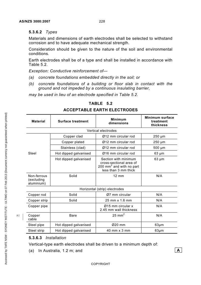
AS/NZS 3000:2007 228
COPYRIGHT
5.3.6.2 Types
Materials and dimensions of earth electrodes shall be selected to withstand corrosion and to have adequate mechanical strength.
Consideration should be given to the nature of the soil and environmental conditions.
Earth electrodes shall be of a type and shall be installed in accordance with Table 5.2.
Exception: Conductive reinforcement of—
(a) concrete foundations embedded directly in the soil; or
(b) concrete foundations of a building or floor slab in contact with the ground and not impeded by a continuous insulating barrier,
may be used in lieu of an electrode specified in Table 5.2.
TABLE 5.2
ACCEPTABLE EARTH ELECTRODES
Material Surface treatment Minimum
dimensions
Minimum surface treatment thickness
Vertical electrodes
Steel
Copper clad Ø12 mm circular rod 250 µm
Copper plated Ø12 mm circular rod 250 µm
Stainless (clad) Ø12 mm circular rod 500 µm
Hot dipped galvanised Ø16 mm circular rod 63 µm
Hot dipped galvanised Section with minimum cross-sectional area of
200 mm2 and with no part
less than 3 mm thick
63 µm
Non-ferrous (excluding aluminium)
Solid 12 mm N/A
Horizontal (strip) electrodes
Copper rod Solid Ø7 mm circular N/A
Copper strip Solid 25 mm x 1.6 mm N/A
Copper pipe Ø15 mm circular x 2.45 mm wall thickness
N/A
Copper cable
Bare 25 mm2 N/A
Steel pipe Hot dipped galvanised Ø20 mm 63µm
Steel strip Hot dipped galvanised 40 mm x 3 mm 63µm
5.3.6.3 Installation
Vertical-type earth electrodes shall be driven to a minimum depth of:
(a) In Australia, 1.2 m; and A
A1
Acc
esse
d by
TA
FE
NS
W -
SY
DN
EY
INS
TIT
UT
E -
ULT
IMO
on
07 F
eb 2
013
(Doc
umen
t cur
renc
y no
t gua
rant
eed
whe
n pr
inte
d)
229 AS/NZS 3000:2007
COPYRIGHT
(b) In New Zealand, 1.8 m
Strip-type earth electrodes buried in a horizontal trench shall be laid at a depth having not less than 0.5 m cover and with a minimum horizontal length of:
(i) In Australia, 3 m.
(ii) In New Zealand, 7.5 m.
5.3.6.4 Location
Earth electrodes shall be installed in a location that satisfies the following conditions:
(a) The electrode maintains effective contact with moist soil that is not subject to excessive drying out.
NOTE: This condition is deemed to be satisfied by locating the electrode—
(a) external to the building in ground that is exposed to the weather; or
(b) in other locations where the ground remains moist because of soil conditions or covers that reduce loss of moisture.
(b) The electrode is separated from conductive enclosures of other buried services, such as water, gas, telecommunications and flammable liquid, in order to reduce possible electrolytic action affecting the electrode or the other service.
NOTE: Separation distances are specified in Table 3.7.
(c) The main earthing conductor connection to an electrode is accessible, in accordance with Clause 5.5.1.2.
The location of the earth electrode shall be identified at the main switchboard.
5.3.7 Functional earthing conductors
Functional earthing conductors that are provided solely to ensure correct operation of electrical equipment, or to permit reliable and proper functioning of electrical installations, need not comply with requirements for main and protective earthing conductors.
Where earthing for combined protective and functional purposes is required, the requirements for protective purposes shall prevail.
It is recommended that the functional earth connection is independent to the protective earth, otherwise it may not comply with the manufacturers requirements. Thus connection would be limited to the main earth connection point.
NOTE: Where a ‘clean earth’ is specified for a particular item of electrical equipment, the manufacturer of the electrical equipment should be consulted in order to confirm the necessary arrangements.
NZ
A
NZ
Acc
esse
d by
TA
FE
NS
W -
SY
DN
EY
INS
TIT
UT
E -
ULT
IMO
on
07 F
eb 2
013
(Doc
umen
t cur
renc
y no
t gua
rant
eed
whe
n pr
inte
d)

AS/NZS 3000:2007 230
COPYRIGHT
5.4 EARTHING OF EQUIPMENT
5.4.1 General
5.4.1.1 Exposed conductive parts
The exposed conductive parts of electrical equipment shall be earthed where the electrical equipment is—
(a) installed or could operate in an earthed situation; or
(b) not installed in an earthed situation but any exposed conductive part of the electrical equipment is electrically continuous with an extraneous conductive part that is located in an earthed situation.
Exception: Electrical equipment need not be earthed where the wiring of the electrical equipment complies with any of the following provisions.
(i) Protection by the use of double insulation.
The following conditions apply:
(A) General
Electrical equipment complying with AS/NZS 3100 for double insulation need not be earthed.
(B) Installation wiring entering equipment
Where cables connecting electrical equipment having double insulation enter the electrical equipment in such a manner that they may come into contact with accessible external conductive parts of the electrical equipment, the cables shall be of a type affording double insulation.
NOTE: Where double insulation is afforded by means of insulated and sheathed cables alone, care should be taken that screws or nails forming part of the structure or equipment are not liable to penetrate the cable, particularly where the cable is subject to movement during maintenance or other operations. See also Clauses 3.9.3 and 3.9.4.
(C) Internal electrical equipment wiring.
Conductors within electrical equipment having double insulation shall be protected, secured or insulated so that, if any one conductor becomes detached from its termination, neither the conductor nor its functional insulation can come into contact with accessible conductive parts.
The attachment of one conductor to another by tying, lacing, clipping or the like, in such a manner as to prevent either conductor coming into contact with accessible conductive parts if it becomes detached from its termination, shall be deemed to comply with this requirement.
(ii) Protection by electrical separation
Exposed conductive parts of electrical equipment supplied in accordance with Clause 7.4 shall not be earthed.
Acc
esse
d by
TA
FE
NS
W -
SY
DN
EY
INS
TIT
UT
E -
ULT
IMO
on
07 F
eb 2
013
(Doc
umen
t cur
renc
y no
t gua
rant
eed
whe
n pr
inte
d)

231 AS/NZS 3000:2007
COPYRIGHT
(iii) Protection by SELV or PELV systems
Exposed conductive parts need not be earthed if supplied by an SELV or a PELV system in accordance with Clause 7.5.
5.4.1.2 Conductive building materials
Conductive building materials shall be earthed in accordance with Clause 5.4.6.
5.4.1.3 Connection of electrical equipment to earth
Equipment required to be earthed shall be arranged for connection to—
(a) protective earthing conductors in the form of cables, cords, busbars or similar forms of current-carrying material; or
(b) another earthing medium, such as conductive parts of cables, wiring enclosures, switchboard framework or the like, in accordance with Clause 5.3.2.
Equipotential bonding shall be arranged in accordance with Clause 5.6.
5.4.2 Socket-outlets
The earthing contact of every socket-outlet shall be earthed.
Exceptions:
1 An earthing contact of a socket-outlet supplied as a separated circuit shall be bonded to the protective bonding system, in accordance with Clause 7.4.
2 In accordance with Clause 7.5.10, a socket-outlet supplied as an extra-low voltage circuit shall not be provided with an earthing contact.
5.4.3 Lighting points
A protective earthing conductor, connected to a terminal or suitably insulated and enclosed, shall be provided at every lighting point, including transformers supplying ELV lighting systems.
Exceptions:
1 A protective earthing conductor shall not be provided for luminaires located in Zone 0 of swimming and spa pools installed in accordance with Clause 6.3.4.5 and Zone 0 of fountains and water features installed in accordance with Clause 6.4.4.5.
2 A protective earthing conductor need not be provided for the following lighting points:
(a) Festoon-type lampholders of the all-insulated type.
(b) Lighting points where the luminaire is earthed by attachment to screwed conductive conduit or pipe in accordance with Clause 5.3.2.3
(c) Lighting points consisting of a luminaire installed outdoors on a non-conductive pole where the luminaire is not in an earthed situation.
(d) ELV lighting points.
A1
Acc
esse
d by
TA
FE
NS
W -
SY
DN
EY
INS
TIT
UT
E -
ULT
IMO
on
07 F
eb 2
013
(Doc
umen
t cur
renc
y no
t gua
rant
eed
whe
n pr
inte
d)
AS/NZS 3000:2007 232
COPYRIGHT
5.4.4 Luminaires
The exposed conductive parts of luminaires shall be earthed.
Exception: Luminaires need not be earthed where—
(a) in accordance with Clause 5.4.1, earthing of equipment is not required; or
(b) in accordance with Clause 5.4.3, a protective earthing conductor is not required; or
(c) installed outdoors on a non-conductive pole and the luminaire is not in an earthed situation; or
(d) supplied at ELV in accordance with Clause 7.5.
5.4.5 Conductive supports for aerial conductors
Conductive poles, posts, struts, brackets, stay wires and other conductive supports for low voltage aerial conductors shall be earthed.
Exceptions:
1 Conductive supports effectively and permanently separated from all conductors by double insulation need not be earthed. An acceptable method would include use of XLPE type X-90UV cable to AS/NZS 3560 with insulated strain clamps and double insulated connectors to AS/NZS 4396.
2 Conductive supports effectively and permanently separated from aerial conductors by insulators mounted on timber, or other insulating supports, need not be earthed where the space between the conductors and the conductive supports is not less than—
(a) for single-core conductors, half the space between the conductors as specified in Clause 3.12.5.4; or
(b) for multi-core conductors, 100 mm.
3 Conductive supports beyond arm’s reach and effectively and permanently separated from any conductive guttering, roof or structural metalwork by a clearance or creepage distance of at least 25 mm need not be earthed.
4 Any stay wire that is attached to a conductive support fitted with a robust strain insulator so that any portion of the stay wire that is within arm’s reach and that is readily accessible, is isolated from the remainder of the stay wire, need not be earthed.
5.4.6 Structural metalwork including conductive building materials
5.4.6.1 General
Parts of structural metalwork, including conductive building materials, shall be earthed where—
(a) the risk of contact with live parts of electrical equipment or insulated, unsheathed cables exists; or
(b) double insulation of cables in contact with structural metalwork is not permanently and effectively maintained.
Acc
esse
d by
TA
FE
NS
W -
SY
DN
EY
INS
TIT
UT
E -
ULT
IMO
on
07 F
eb 2
013
(Doc
umen
t cur
renc
y no
t gua
rant
eed
whe
n pr
inte
d)
233 AS/NZS 3000:2007
COPYRIGHT
The breaking of a conductor at a termination shall not result in contact between unearthed conductive building material and—
(i) live parts; or
(ii) parts separated from live parts by single insulation.
This requirement may be satisfied by—
(A) restraining the conductor by tying, lacing or clipping; or
(B) containing the termination within a non-conductive shroud or enclosure.
5.4.6.2 Domestic electrical installations
Structural metalwork forming the frame of a dwelling shall be earthed.
5.4.6.3 Connection to protective earthing conductors
Earthing of parts of structural metalwork, including conductive building materials, may be effected by the connection of a protective earthing conductor of appropriate size at one point of the metalwork provided that the resistance between the earth bar and any part required to be earthed does not exceed 0.5 Ω.
5.4.7 Submersible pumps
The exposed conductive parts of a submersible pump shall be earthed by means of a protective earthing conductor that is terminated at the pump motor.
The termination shall be made in a manner that provides suitable sealing against ingress of moisture, protection against possible mechanical damage and corrosion likely to occur at the point of installation.
This requirement may be satisfied by terminating the protective earthing conductor on the motor at—
(a) a terminal incorporated in a housing; or
(b) an internal or external constructional component, in accordance with Clause 5.5.6.2.
5.4.8 Variable frequency devices
Devices that produce high frequency currents in the protective earth may produce touch voltages that are dangerous to persons and livestock.
NOTES:
1 The touch voltages may be as much as a 100 V but the manufacturer’s advice should be sought when installing this type of device. These high frequency voltages may not be detectable using normal 50 Hz test instruments. An oscilloscope and ballast resistor should be used.
2 Attention is drawn to the safety requirements for electronic equipment in AS 62103.
A2
Acc
esse
d by
TA
FE
NS
W -
SY
DN
EY
INS
TIT
UT
E -
ULT
IMO
on
07 F
eb 2
013
(Doc
umen
t cur
renc
y no
t gua
rant
eed
whe
n pr
inte
d)

AS/NZS 3000:2007 234
COPYRIGHT
5.5 EARTHING ARRANGEMENTS
5.5.1 Main earthing conductor
5.5.1.1 Arrangement
An earthing conductor, deemed to be the main earthing conductor, shall be taken from the main earthing terminal/connection or bar at the main switchboard to an earth electrode complying with Clause 5.3.6.
The main earthing conductor shall be run in as direct a manner as possible and shall not be directly connected to the terminal of any accessory, luminaire or appliance.
Exceptions:
1 The main earthing conductor may be taken to an earth bar or link within a customer’s substation forming part of the electrical installation.
2 The main earthing conductor may be taken to an earthing conductor or terminal, provided by the distributor or, if required by the distributor, to a distributor neutral bar or link within the electrical installation.
NOTE: An earthing conductor or terminal provided by the distributor may include a special earthing conductor, the conductive sheath of a supply cable, or a neutral bar or link at a substation.
5.5.1.2 Connection to earth electrode
The connection of the main earthing conductor to the earth electrode shall—
(a) be accessible for visual inspection and for the purposes of testing; and
NOTES:
1 Where necessary, access by means of an underground pit with its cover accessible above ground is considered acceptable, provided adequate space is available for the connection of test leads and the pit is suitably identified as to its purpose.
2 Where the reinforcing steel is used as the earth electrode, this testing condition is deemed to be satisfied by the provision of a test point on the main earthing electrode.
(b) be made by means of a suitable device in accordance with the manufacturer’s specification that provides adequate electrical conductivity; and
(c) provide protection against mechanical damage likely to occur to the main earthing conductor or the connection to the electrode at the location, in accordance with Clause 5.5.5.2; and
(d) be suitably protected against corrosion in accordance with Clause 5.5.5.3.
NOTE: For location of earth electrodes, see Clause 5.3.6.4.
Acc
esse
d by
TA
FE
NS
W -
SY
DN
EY
INS
TIT
UT
E -
ULT
IMO
on
07 F
eb 2
013
(Doc
umen
t cur
renc
y no
t gua
rant
eed
whe
n pr
inte
d)
235 AS/NZS 3000:2007
COPYRIGHT
5.5.1.3 Labelling
The main earthing conductor shall have a permanent label attached at the connection to the earth electrode with a legible warning against disconnection in the following form:
WARNING: ‘MAIN ELECTRICAL EARTHING CONDUCTOR—DO NOT
DISCONNECT’
Exception: Where the method of connection to the electrode precludes disconnection this requirement need not apply.
5.5.1.4 Resistance
The resistance of the main earthing conductor, measured between the main earthing terminal/connection or bar and the earth electrode, including the connection to the earth electrode, shall be not more than 0.5 Ω.
5.5.2 Protective earthing conductors
5.5.2.1 Arrangement
All submain and subcircuit protective earthing conductors shall be directly connected to the main earthing conductor or to another point on an earthing system that is connected to the main earthing conductor.
The connection shall be made at one or a combination of the following points:
(a) An earthing terminal/connection or bar at the main switchboard provided specifically for the connection of earthing conductors and that is directly connected to the main earthing conductor.
(b) Any point on the main earthing conductor.
(c) An earthing terminal/connection or bar at a distribution board provided specifically for the connection of protective earthing conductors and arranged to comply with Clause 5.5.2.2.
(d) Any point on a protective earthing conductor providing facilities for earthing at a distribution board and arranged to comply with Clause 5.5.2.2.
NOTES:
1 Examples of earthing connections are shown in Figure 5.3.
2 Refer to Clause 5.5.3.1 where the earthing system in an outbuilding is to be treated as a separate MEN installation.
5.5.2.2 Restricted connections
5.5.2.2.1 Circuits
The protective earthing conductor for a circuit that is incorporated in the same cable sheath or wiring enclosure as the associated live conductors for the circuit shall only be used for the earthing of equipment supplied from the circuit.
Exception: This does not preclude an unenclosed common protective earthing conductor being used for a number of different circuits.
A2
Acc
esse
d by
TA
FE
NS
W -
SY
DN
EY
INS
TIT
UT
E -
ULT
IMO
on
07 F
eb 2
013
(Doc
umen
t cur
renc
y no
t gua
rant
eed
whe
n pr
inte
d)
AS/NZS 3000:2007 236
COPYRIGHT
5.5.2.2.2 Earthing of equipment
A protective earthing conductor that originates at a distribution board, in accordance with Clause 5.5.2.1 (c) or (d), shall not be used for the earthing of electrical equipment that is supplied from another switchboard.
5.5.2.2.3 Earthing facilities for distribution boards
A protective earthing conductor that originates at a distribution board, in accordance with Clause 5.5.2.1 (c) or (d), shall not be used for the provision of earthing facilities for another distribution board.
Exceptions:
1 This requirement need not apply where earthing facilities for a distribution board originate from the same distribution board as the associated active conductors supplying the distribution board.
2 A common protective earthing conductor connected to the main earthing conductor in accordance with Clause 5.5.2.1 (a) or (b) may be arranged to provide earthing facilities at a number of distribution boards provided that—
(a) the continuity of the protective earthing conductor shall not be dependent on a terminal at a distribution board; and
(b) a direct connection shall be made between the common protective earthing conductor and any branch protective earthing conductor to a distribution board.
Acc
esse
d by
TA
FE
NS
W -
SY
DN
EY
INS
TIT
UT
E -
ULT
IMO
on
07 F
eb 2
013
(Doc
umen
t cur
renc
y no
t gua
rant
eed
whe
n pr
inte
d)
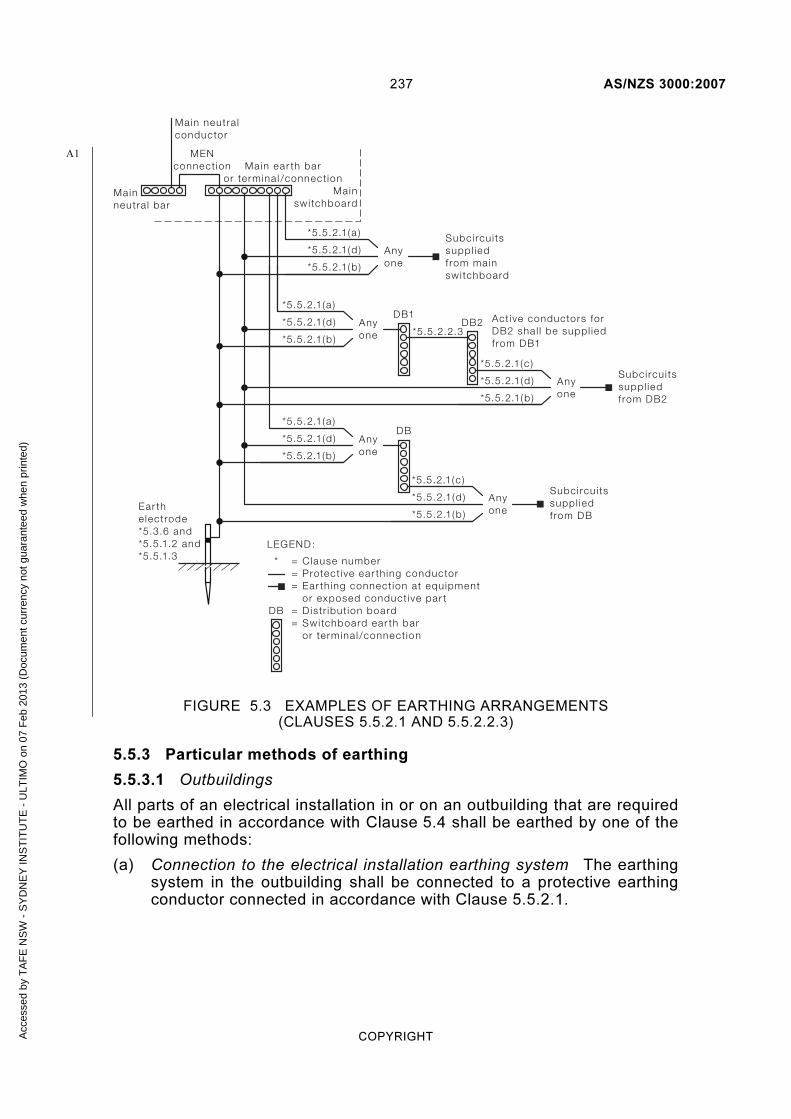
237 AS/NZS 3000:2007
COPYRIGHT
Anyone
Subci rcu i tssuppl iedf rom mainswi tchboard
Anyone
*5.5.2.1(a )
*5.5.2.1(d )
*5.5.2.1(b )
Anyone
DB1DB2 Active conductors for
DB2 sha l l be suppl iedf rom DB1
*5.5.2.1(a )
*5.5.2.2.3*5.5.2.1(d )
*5.5.2.1(b )
Anyone
DB*5.5.2.1(a )
Ear the lectrode*5.3.6 and*5.5.1.2 and*5.5.1.3
*5.5.2.1(d )
*5.5.2.1(b )
*5.5.2.1(c )
*5.5.2.1(c )
*5.5.2.1(d )
*5.5.2.1(b )
Anyone
Subci rcu i tssuppl iedf rom DB
Subci rcu i tssuppl iedf rom DB2
*5.5.2.1(d )
*5.5.2.1(b )
Mainswi tchboard
Main ear th baror termina l /connect ion
Main neutra lconductor
Mainneutra l bar
DB
*
LEGEND:
Clause numberProtect ive ear th ing conductorEar th ing connect ion at equipmentor exposed conduct ive par tD istr ibut ion boardSwitchboard ear th baror termina l /connect ion
===
==
MENconnect ion
FIGURE 5.3 EXAMPLES OF EARTHING ARRANGEMENTS (CLAUSES 5.5.2.1 AND 5.5.2.2.3)
5.5.3 Particular methods of earthing
5.5.3.1 Outbuildings
All parts of an electrical installation in or on an outbuilding that are required to be earthed in accordance with Clause 5.4 shall be earthed by one of the following methods:
(a) Connection to the electrical installation earthing system The earthing system in the outbuilding shall be connected to a protective earthing conductor connected in accordance with Clause 5.5.2.1.
A1
Acc
esse
d by
TA
FE
NS
W -
SY
DN
EY
INS
TIT
UT
E -
ULT
IMO
on
07 F
eb 2
013
(Doc
umen
t cur
renc
y no
t gua
rant
eed
whe
n pr
inte
d)

AS/NZS 3000:2007 238
COPYRIGHT
(b) Separate MEN installation The earthing system in the outbuilding shall be connected to the submain neutral conductor supplying the outbuilding. In this case the submain neutral conductor supplying the outbuilding is a combined protective earthing and neutral (PEN) conductor.
The electrical installation in the outbuilding shall be regarded as a separate electrical installation, and shall be earthed in accordance with other relevant Clauses of this Standard and with the following requirements:
(i) There shall be not more than one MEN connection in any one outbuilding.
(ii) The distribution board in the outbuilding shall be regarded as a main switchboard for the purpose of effecting the MEN connection.
(iii) The earthing conductor between the distribution board in the outbuilding and the earth electrode shall be regarded as a main earthing conductor for the purposes of earthing of the electrical installation in the outbuilding.
(iv) The submain supplying the outbuilding shall be run either—
(A) directly from the main switchboard; or
(B) from the main switchboard via distribution boards in one or more other outbuildings, to one distribution board only in the outbuilding.
(v) Where the combined protective earthing and neutral (PEN) conductor supplying the distribution board in the outbuilding runs from the main switchboard via distribution boards in one or more other outbuildings, the terminals on such distribution boards shall not be depended on for continuity of the combined protective earthing and neutral (PEN) conductor.
(vi) The combined protective earthing and neutral (PEN) conductor supplying the distribution board in the outbuilding should not be connected in parallel, by means of earthing or equipotential bonding conductors, with conductive pipes or structural metal within the electrical installation.
NOTE: Particular care is required where conductive pipes and such items as telecommunication cable sheaths, covered walkways, etc may be continuous between separate buildings and thus establish a parallel earth/neutral path.
5.5.3.2 Wiring systems
(a) Conductive wiring enclosures Exposed conductive parts of wiring enclosures shall be earthed at the end adjacent to the switchboard or accessory at which the wiring enclosure originates.
(b) Conductive sheaths, armours and screens of cables or cords The conductive sheathing, armouring or screening of cables or cords required to be earthed shall be earthed at the end adjacent to the switchboard or accessory at which the cable or cord originates.
Acc
esse
d by
TA
FE
NS
W -
SY
DN
EY
INS
TIT
UT
E -
ULT
IMO
on
07 F
eb 2
013
(Doc
umen
t cur
renc
y no
t gua
rant
eed
whe
n pr
inte
d)

239 AS/NZS 3000:2007
COPYRIGHT
Exceptions:
1 A conductive screen or braid embodied in a cable or flexible cord need not be earthed where—
(a) it is separated from the live conductors by double insulation; and
(b) sheathed or covered overall with non-conductive material; and
(c) all joints to and terminations of the screen or braid are suitably separated from exposed conductive and live parts.
2 A conductive cable sheathing, armouring, screening or braiding need not be earthed where, in accordance with Clause 5.4.1, earthing is not required.
5.5.3.3 Earthing of electrical equipment supplied by flexible cord or flexible cable
The exposed conductive parts of electrical equipment supplied by flexible cord or flexible cable shall be earthed by connection to a protective earthing conductor incorporated with the associated live conductors in the sheath, braid or enclosure of the supply cord or cable.
5.5.3.4 Switchboards
Electrical equipment mounted on the conductive framework of a switchboard may be earthed in accordance with Clause 5.3.2.3 (c).
5.5.3.5 Unprotected consumers mains
Exposed conductive parts associated with consumers mains not provided with short-circuit protection on the supply side shall be earthed by a conductor with a current-carrying capacity not less than that of the main neutral conductor.
This conductor shall be connected to—
(a) the main neutral conductor or bar; or
(b) the main earthing terminal/connection or bar, in which case, in accordance with Clause 5.3.5.2, the cross-sectional area of the MEN connection shall be not less than that of the main neutral conductor.
NOTES:
1 Where double insulation of the consumers mains conductors is maintained up to the supply terminal/s of the service protective device/s, and short-circuit protection is provided by that device, this requirement need not apply.
2 A system that is deemed to provide double insulation for aerial conductors would include use of XLPE type X-90UV cable to AS/NZS 3560 with insulated strain clamps and double insulated connectors to AS/NZS 4396.
3 Exposed conductive parts associated with consumers mains include—
(a) switchboard cases, surrounds and enclosures; and
(b) wiring enclosures; and
(c) boxes and accessories; and
(d) supports for aerial conductors
Acc
esse
d by
TA
FE
NS
W -
SY
DN
EY
INS
TIT
UT
E -
ULT
IMO
on
07 F
eb 2
013
(Doc
umen
t cur
renc
y no
t gua
rant
eed
whe
n pr
inte
d)

AS/NZS 3000:2007 240
COPYRIGHT
4 A distributor’s upstream service protective device may provide short-circuit protection of consumers mains.
5.5.4 Continuity
5.5.4.1 General
Earthing conductors shall be suitably protected against mechanical and chemical deterioration and electrodynamic forces. Star or cutting washers or similar devices that effectively cut through paint or similar coatings are considered to be an acceptable method of ensuring earth continuity across bolted or clamped joints between metal equipment panels or framework that have painted or coated surfaces.
5.5.4.2 Conductive wiring enclosures
Conductive wiring enclosures and associated fittings that require to be earthed, including those used as an earthing medium, shall be mechanically and electrically continuous. The impedance of such a wiring enclosure earthing arrangement shall be in accordance with Clause 5.7.
5.5.4.3 Conductive sheaths, armours and screens of cables
Conductive sheaths, armours and screens of cables and associated fittings that require to be earthed, including those used as an earthing medium, shall be mechanically and electrically continuous. The impedance of such cable components and associated fittings providing earth continuity shall be in accordance with that required for a copper earthing conductor determined in accordance with Clause 5.3.3.
5.5.4.4 Connecting devices
Where electrical equipment is connected to the installation wiring by a connection in the form of a plug and socket-outlet, appliance plug or similar connecting device, any connection of exposed conductive parts to earth shall be—
(a) made automatically, before the live connections are made, when any plug portion is inserted in the corresponding socket-outlet; and
(b) broken automatically, not before the live connections are broken, when any plug portion is withdrawn from the corresponding socket-outlet.
5.5.5 Installation
5.5.5.1 General
All earthing conductors and other forms of earthing medium shall be installed in a manner that provides adequate protection against likely mechanical damage, inadvertent interference and chemical deterioration.
NOTE: In areas of high lightning activity, the provisions of AS/NZS 1768 should be considered.
5.5.5.2 Protection against mechanical damage
Earthing conductors shall be protected against becoming displaced, damaged or cut by means of one or a combination of the following methods appropriate to the expected conditions of mechanical damage at the point of installation:
Acc
esse
d by
TA
FE
NS
W -
SY
DN
EY
INS
TIT
UT
E -
ULT
IMO
on
07 F
eb 2
013
(Doc
umen
t cur
renc
y no
t gua
rant
eed
whe
n pr
inte
d)

241 AS/NZS 3000:2007
COPYRIGHT
(a) Fixing by means of clamps, clips, saddles, clouts or similar devices that shall not pass between the strands of the conductor or damage the conductor.
(b) Guarding by metallic barriers or other suitable robust material.
(c) Installing in a wiring enclosure, in accordance with Clause 3.10.2.
5.5.5.3 Protection against corrosion
Earthing conductors, and any associated fixing devices, shall be protected from corrosion, including the effects of moisture or contact with dissimilar metals.
Earthing conductors and associated fittings and fixing devices shall comply with the following requirements:
(a) Underground and damp situations All joints and terminations installed in an underground location or other damp situation shall be sealed to prevent the entry of moisture. All associated fittings and fixing devices in such locations shall be constructed of, or protected by, corrosion-resistant material.
(b) Exposed to the weather All joints, terminations, fittings and fixtures in locations exposed to the weather shall be constructed of, or protected by, corrosion-resistant material in such a manner that will prevent the entry of moisture affecting the conductor.
5.5.5.4 Aerial earthing conductors
Aerial earthing conductors shall be—
(a) supported in accordance with Clause 3.12.5; and
(b) identified in accordance with Clause 3.8.3.4.
5.5.5.5 Buried earthing conductors
(a) Installation conditions: A bare or insulated earthing conductor buried direct in the ground or installed in an underground enclosure shall be subject to the depth of laying and mechanical protection requirements appropriate to the method of installation for a sheathed conductor, in accordance with Clause 3.11.
(b) Bare earthing conductors In addition, bare earthing conductors shall be buried direct in the ground or installed in an underground enclosure only where they are copper not less than 25 mm2.
(c) Walls and partitions An earthing conductor that passes through a wall or partition shall not be considered as a buried earthing conductor.
5.5.6 Connections
5.5.6.1 Conductors
Connections in earthing conductors shall comply with Clause 3.7.
A1
Acc
esse
d by
TA
FE
NS
W -
SY
DN
EY
INS
TIT
UT
E -
ULT
IMO
on
07 F
eb 2
013
(Doc
umen
t cur
renc
y no
t gua
rant
eed
whe
n pr
inte
d)

AS/NZS 3000:2007 242
COPYRIGHT
5.5.6.2 Constructional components
The exposed conductive parts of electrical equipment may be earthed by the connection of a protective earthing conductor to a constructional bolt, stud, screw or similar terminal arrangement forming an integral part of the electrical equipment.
Such earthing shall be in accordance with the following requirements:
(a) The terminal shall be mechanically and electrically continuous with the exposed conductive part to be earthed.
(b) The protective earthing conductor shall be capable of being removed from the terminal without—
(i) reducing the effectiveness of the bolt, stud, or screw as a constructional medium in any way; or
(ii) causing any parts of the electrical equipment to lose their relative rigidity.
A stud that also serves for securing a terminal cover may be used provided that it complies with Items (c) and (d).
(c) The removal of any covers or parts that are likely to be removed to—
(i) obtain access to terminals; or
(ii) adjust the electrical equipment or parts thereof;
shall not disturb or reduce the effectiveness of the earthing connection.
(d) The bolt, stud or screw shall not be used to—
(i) fix the electrical equipment in position; or
(ii) adjust the position of the electrical equipment or any part of it.
5.6 EQUIPOTENTIAL BONDING
5.6.1 General
Equipotential bonding is intended to minimize the risks associated with the occurrence of voltage differences between exposed conductive parts of electrical equipment and extraneous conductive parts.
NOTE: Such voltage differences can arise from a range of sources including, but not limited to—
(a) a fault external to the installation, either on an incoming extraneous conductor (such as a water or gas pipe, etc.) or on the supply neutral and protective earthing system; and
(b) distribution system load current in the soil passing through a swimming pool; and
(c) telecommunication system voltages on equipment adjacent to exposed conductive parts; and
(d) lightning discharges either directly within the installation or effecting the incoming extraneous conductor or the supply mains .
Acc
esse
d by
TA
FE
NS
W -
SY
DN
EY
INS
TIT
UT
E -
ULT
IMO
on
07 F
eb 2
013
(Doc
umen
t cur
renc
y no
t gua
rant
eed
whe
n pr
inte
d)

243 AS/NZS 3000:2007
COPYRIGHT
5.6.2 Arrangement
5.6.2.1 General
Equipotential bonding arrangements shall be provided in accordance with Clauses 5.6.2.2 to 5.6.2.6 to avoid any potential differences that may occur between electrical equipment connected to the electrical installation earthing system and any conductive piping (and including taps, etc) that may independently be in contact with the mass of earth (see Figures 5.4 and 5.5).
NOTE: Additional equipotential bonding requirements apply for—
(a) patient areas of hospitals, medical and dental practices and dialyzing locations, in accordance with AS/NZS 3003; and
(b) explosive atmospheres in accordance with Clause 7.7; and
(c) telecommunications installations, in accordance with AS/NZS 3015; and
(d) film, video and television sites, in accordance with AS/NZS 4249; and
(e) photovoltaic arrays, in accordance with AS/NZS 5033; and
(f) general access floors (elevated floors), in accordance with AS 4154; and
(g) generating systems, in accordance with Clause 7.3; and
(h) separated circuits, in accordance with Clause 7.4.
5.6.2.2 Conductive water piping
Conductive water piping that is both—
(a) installed and accessible within the building containing the electrical installation; and
(b) continuously conductive from inside the building to a point of contact with the ground,
shall be bonded to the earthing system of the electrical installation.
Any equipotential bonding of conductive water piping shall be effected by means of an equipotential bonding conductor connected to the main earthing conductor or earth terminal or bar.
The connection of the bonding conductor to the conductive water piping shall be as close as practicable to the entry of the conductive water piping to the building.
NOTES:
1 The main earthing conductor may be continued beyond the earth electrode connecting device to form the equipotential bonding conductor to the conductive water piping. A separate connection to the earth electrode does not constitute a connection to the main earthing conductor and does not comply with this Clause.
2 Item (b) above includes any conductive path through an item of equipment, e.g. a water heater.
A2
Acc
esse
d by
TA
FE
NS
W -
SY
DN
EY
INS
TIT
UT
E -
ULT
IMO
on
07 F
eb 2
013
(Doc
umen
t cur
renc
y no
t gua
rant
eed
whe
n pr
inte
d)

AS/NZS 3000:2007 244
COPYRIGHT
Al l conduct ivewater p ip ing.
Interna l access.
Equipotent ia lbonding requi red.
LEGEND:= Conduct ive water p ip ing= Non-conduct ive water p ip ing
Non-conduct ivewater p ip ing inwal l cav i t y.
No interna l access.
Equipotent ia lbonding notrequi red.
FIGURE 5.4 EXAMPLES OF EQUIPOTENTIAL BONDING OF CONDUCTIVE WATER PIPING
Acc
esse
d by
TA
FE
NS
W -
SY
DN
EY
INS
TIT
UT
E -
ULT
IMO
on
07 F
eb 2
013
(Doc
umen
t cur
renc
y no
t gua
rant
eed
whe
n pr
inte
d)

245 AS/NZS 3000:2007
COPYRIGHT
Non-conduct ivewater p ip ingunder f loor andin wal l cav i t y.
Interna l access.
Equipotent ia lbonding notrequi red.
Non-conduct ivewater p ip ingf rom ground toconduct ive p ip ing.
Interna l access.
Equipotent ia lbonding notrequi red.
LEGEND:= Conduct ive water p ip ing= Non-conduct ive water p ip ing
*
**
NOTE: Bonding recommended i f conduct ive path ex ists f rom tap to ground through bui ld ing mater ia ls
FIGURE 5.5 EXAMPLES OF EQUIPOTENTIAL BONDING OF CONDUCTIVE WATER PIPING (WITH EXCEPTION)
5.6.2.3 Other conductive piping systems
Conductive piping systems associated with fire sprinklers, gas, water or flammable liquid that are unavoidably in contact with the exposed conductive parts of wiring enclosures, cable components or other electrical equipment shall be connected to such equipment by means of an equipotential bonding conductor.
Exception: Bonding need not be provided where the piping system is effectively earthed by connection to an associated item of electrical equipment, e.g. pipes connected to electric hot water systems.
5.6.2.4 Conductive cable sheaths and conductive wiring enclosures
The conductive sheath, armour or conductive wiring enclosure of conductors operating at above extra-low voltage shall—
(a) be bonded to any conductive pipes containing flammable agents, such as gas or oil, with which they are in contact. The bonding shall be arranged to prevent appreciable voltage differences at points of contact; or
A1
Acc
esse
d by
TA
FE
NS
W -
SY
DN
EY
INS
TIT
UT
E -
ULT
IMO
on
07 F
eb 2
013
(Doc
umen
t cur
renc
y no
t gua
rant
eed
whe
n pr
inte
d)

AS/NZS 3000:2007 246
COPYRIGHT
(b) where it is impracticable to achieve the bonding required by Item (a), the conductive cable sheath, armour or conductive wiring enclosures shall be separated from any non-earthed conductive pipes containing flammable agents. This separation shall overlap the points of crossing by 25 mm in all directions and be—
(i) a rigid spacing of 25 mm in air; or
(ii) a 6 mm thickness of durable insulating material.
5.6.2.5 Showers and bathrooms
Any conductive reinforcing within a concrete floor or wall of a room containing a shower or bath shall be bonded to the earthing system of the electrical installation.
An equipotential bonding conductor, in accordance with Clause 5.6.3, shall be connected between the reinforcing material and any part of the earthing system.
NOTES:
1 This requirement is intended to avoid any potential differences that may occur between conductive material connected to, or in contact with, the electrical installation earthing system or earthed electrical appliances and the concrete floor or wall.
2 A conductive grille or reinforcement mesh laid in the floor and connected to the equipotential bonding conductor may also be used.
3 Conductive tie-wires used during construction of reinforced concrete structures are considered to be an adequate electrical bond between the conductive reinforcing components. Provided that the reinforcement is satisfactorily electrically connected together, one point of connection of the bonding conductor to the reinforcement is satisfactory where bonding is required at more than one location.
4 Although not a requirement for existing concrete floors or walls, the practice should be adopted wherever practicable.
5.6.2.6 Swimming and spa pools
5.6.2.6.1 Electrical equipment
The following items associated with electrical equipment shall be equipotentially bonded:
(a) The exposed conductive part of any electrical equipment in the classified pool zones.
(b) Any exposed conductive parts of electrical equipment that are not separated from live parts by double insulation and that are in contact with the pool water, including water in the circulation or filtering system.
A1
A2
Acc
esse
d by
TA
FE
NS
W -
SY
DN
EY
INS
TIT
UT
E -
ULT
IMO
on
07 F
eb 2
013
(Doc
umen
t cur
renc
y no
t gua
rant
eed
whe
n pr
inte
d)

247 AS/NZS 3000:2007
COPYRIGHT
NOTES:
1 Where electrical appliances and luminaires are supplied as a separated circuit in accordance with Clause 7.4, all conductive parts of such electrical equipment are deemed to be separated from live parts by double insulation.
2 Underwater luminaire bezels should be made of plastics and any associated fixing screws be insulated or of insulating material.
5.6.2.6.2 Conductive fixtures and fittings
Where any of the items described in Clause 5.6.2.6.1 are required to be equipotentially bonded, the bonding shall be extended to the following items:
(a) Any conductive fittings within or attached to the pool, such as pool ladders and diving boards.
(b) Any fixed conductive material within arm’s reach of the pool edge, such as conductive fences, lamp standards and pipework. Refer to Clause 1.4.12 and Figure 1.1 for the zone of arm’s reach.
NOTE: Fixed conductive parts and fittings that are not part of electrical equipment and that are not more than 100 mm in any dimension need not be bonded.
5.6.2.6.3 Conductive pool structures
Where the pool structure is conductive, all extraneous conductive parts, including the reinforcing metal of the pool shell or deck, shall be connected to an equipotential bonding connection point complying with Clause 5.6.2.6.4.
Where any of the items described in Clause 5.6.2.6.1 are required to be equipotentially bonded, the bonding shall be extended to the conductive pool structure by means of the equipotential bonding connection point.
NOTES:
1 Connections to the conductive reinforcement of the pool will generally be subject to the effects of water during the construction phase and to subsequent dampness.
2 Conductive tie-wires used during construction of reinforced concrete pools are considered to be an adequate electrical bond between the conductive reinforcing components. Provided that the reinforcement is satisfactorily electrically connected together, one point of connection of the bonding conductor to the reinforcement is satisfactory where bonding is required by Clause 5.6.2.6.2(a).
5.6.2.6.4 Equipotential bonding conductor connection point
A connection point shall be provided at the swimming or spa pool location for the bonding connection to be made to the conductive parts of the pool structure. Where equipotential bonding is required, the connection point may also be used as a common point for the connection of other conductive fixtures and fittings to the bonding arrangement.
A2
Acc
esse
d by
TA
FE
NS
W -
SY
DN
EY
INS
TIT
UT
E -
ULT
IMO
on
07 F
eb 2
013
(Doc
umen
t cur
renc
y no
t gua
rant
eed
whe
n pr
inte
d)

AS/NZS 3000:2007 248
COPYRIGHT
The connection point shall be—
(a) located in a position that will be accessible with space for connections to be made after pool construction (for example, a pit located adjacent to the pool equipment);
(b) identified by marking of the location on the switchboard at which the circuits supplying the pool or spa originate, or other permanent location;
(c) of suitable design and construction in accordance with Clause 3.7;
(d) protected against mechanical damage in accordance with Clause 5.5.5.2; and
(e) protected against corrosion in accordance with Clause 5.5.5.3.
5.6.2.6.5 Bonding arrangement
An equipotential bonding conductor, in accordance with Clause 5.6.3, shall be connected between—
(a) the electrical equipment items described in Clause 5.6.2.6.1;
(b) the conductive fixtures and fittings in Clause 5.6.2.6.2;
(c) the conductive pool structure or bonding connection point in Clause 5.6.2.6.3; and
(d) the earthing conductors associated with each circuit supplying the pool or spa, or the earthing bar at the switchboard at which the circuits originate.
5.6.2.7 Telephone and telecommunication earthing systems
The telephone and telecommunication earthing system may be connected in common with the electrical installation earthing system in order to minimize the risk associated with different voltages appearing on the two systems.
If the telephone and telecommunication earthing system is directly connected to the electrical installation earthing system it shall be connected—
(a) to the electrical installation earthing system at an enclosed terminal provided for the purpose; or
(b) directly to the earth electrode by an independent connecting device and shall be clearly identified.
If an enclosed terminal is used the following conditions shall apply:
(i) The terminal shall be connected by means of a protective earthing conductor to the main earthing conductor of the electrical installation earthing system in accordance with the connection methods described in Clause 5.5.2.
(ii) The terminal shall not be installed within a switchboard.
(iii) The terminal shall be installed in a convenient and readily accessible position.
A2
Acc
esse
d by
TA
FE
NS
W -
SY
DN
EY
INS
TIT
UT
E -
ULT
IMO
on
07 F
eb 2
013
(Doc
umen
t cur
renc
y no
t gua
rant
eed
whe
n pr
inte
d)

249 AS/NZS 3000:2007
COPYRIGHT
(iv) The minimum cross-sectional area of the protective earthing conductor used for the connection shall be 6 mm2.
NOTES:
1 Requirements for the installation of telecommunications earthing systems in Australia, are contained in AS/ACIF S009 Installation requirements for customer cabling (Wiring Rules).
2 Recommendations for New Zealand are contained in the TCF Premises Wiring Code of Practice.
3 Refer to Appendix F for further detail of the bonding arrangement.
5.6.3 Bonding conductors
5.6.3.1 General
The selection and installation requirements for equipotential bonding conductors shall be in accordance with this Standard for protective earthing conductors.
Exception: The size of an equipotential bonding conductor shall be determined in accordance with Clause 5.6.3.2.
5.6.3.2 Size
The size of equipotential bonding conductors shall be determined from the requirements of this Clause 5.6.3.2 appropriate to the particular bonding conductor application.
The equipotential bonding conductor need not be larger than these sizes provided that the installation conditions are such that mechanical damage is unlikely to occur and, in accordance with Clause 5.7.5, a larger size is not required to reduce the earth fault-loop impedance.
(a) Conductive piping, cable sheaths and wiring enclosures The equipotential bonding conductor required in accordance with Clauses 5.6.2.2 to 5.6.2.4 shall have a cross-sectional area not less than 4 mm2.
(b) Showers, bathrooms, swimming and spa pools The equipotential bonding conductors required to connect conductive parts of a shower, bathroom, swimming or spa pool in accordance with Clauses 5.6.2.5 and 5.6.2.6 shall have a cross-sectional area not less than 4 mm2.
Exception: The cross-sectional area of the equipotential bonding conductor for a swimming or spa pool may be determined as for an earthing conductor, in accordance with Clause 5.3.3.4 (c), where the equipotential bonding conductor is incorporated in a multi-core flexible cord supplying electrical equipment that is required to be removed for maintenance.
(c) Telephone and telecommunication earthing systems The equipotential bonding conductors required to connect a telephone and telecommunication earthing system in accordance with Clause 5.6.2.7 shall have a cross-sectional area not less than 6 mm2.
NOTE: Refer to the AS/NZS 60079 series for minimum sizes of equipotential bonding cnductors in explosive atmospheres.
A
NZA2
A2
Acc
esse
d by
TA
FE
NS
W -
SY
DN
EY
INS
TIT
UT
E -
ULT
IMO
on
07 F
eb 2
013
(Doc
umen
t cur
renc
y no
t gua
rant
eed
whe
n pr
inte
d)

AS/NZS 3000:2007 250
COPYRIGHT
5.7 EARTH FAULT-LOOP IMPEDANCE
5.7.1 General
Effective fault protection by means of automatic disconnection of supply is based on disconnecting supply from the section of the installation concerned in such a way as to limit the time/touch voltage relationship to safe values in the event of an insulation fault.
Automatic disconnection is dependent on the characteristics of the circuit-protective device and the impedance of the earthing system.
Where the touch potential exceeds 50 V a.c or 120 V ripple-free d.c. the circuit-protective device shall cause disconnection of supply within the required time.
The impedance of the earthing system shall be limited to that which will generate sufficient current in the protective device to cause operation of that device within the required time.
NOTE: Appendix B provides a detailed analysis of earth fault-loop impedance as an element of the method of protection by automatic disconnection of supply.
5.7.2 Disconnection times
The maximum disconnection time for a 230 V supply voltage shall not exceed the following:
(a) 0.4 s for final subcircuits that supply—
(i) socket-outlets having rated currents not exceeding 63 A; or
(ii) hand-held Class I equipment; or
(iii) portable equipment intended for manual movement during use.
(b) 5 s for other circuits where it can be shown that people are not exposed to touch voltages that exceed safe values.
NOTES:
1 Maximum disconnection times will vary for other operating voltages or installation conditions, such as wet locations, etc.
2 The fault current must be of sufficient magnitude to cause automatic disconnection within the required times.
5.7.3 Earth fault-loop
The path for the circulation of fault current, the earth fault-loop, in a MEN system comprises the following parts (see Appendix B, Figure B5):
(a) The active conductor as far as the point of the fault, including supply mains, service line, consumers mains, submains (if any) and the final subcircuit.
(b) The protective earthing conductor (PE), including the main earthing terminal/connection or bar and MEN connection.
(c) The neutral-return path, consisting of the neutral conductor (N) between the main neutral terminal or bar and the neutral point at the transformer, including supply mains, service line and consumers mains.
Acc
esse
d by
TA
FE
NS
W -
SY
DN
EY
INS
TIT
UT
E -
ULT
IMO
on
07 F
eb 2
013
(Doc
umen
t cur
renc
y no
t gua
rant
eed
whe
n pr
inte
d)

251 AS/NZS 3000:2007
COPYRIGHT
(d) The path through the neutral point of the transformer and the transformer winding.
5.7.4 Impedance
The earthing system impedance and characteristics of protective devices shall be such that, if a fault of negligible impedance occurs anywhere in the electrical installation between an active conductor and an exposed conductive part or protective earthing conductor, automatic disconnection of the supply will occur within the specified time.
The following condition fulfils this requirement:
Zs × Ia ≤ Uo 5.2
Where
Zs = the impedance of the earth fault-loop comprising the source, the active conductor up to the point of the fault and the return conductor between the point of the fault and the source
Ia = the current required to cause the automatic operation of the disconnecting protective device within the required disconnection time
Uo = the nominal a.c. r.m.s. voltage to earth (230 V)
NOTES:
1 Additional earthing requirements apply in patient areas of hospitals, medical and dental practices and dialyzing locations. Refer AS/NZS 3003.
2 The return path will comprise both protective earthing and neutral conductors.
3 Appendix B illustrates a method of complying with the requirements of this Clause based on the determination of the maximum length of a circuit in relation to the size of circuit conductors and type of protective device.
4 Guidance on the measurement of the earth fault-loop impedance of each circuit is given in Appendix B.
Table 8.1 contains calculated examples of the maximum values of earth fault-loop impedance, Zs, using approximate mean tripping currents for a limited range of miniature circuit-breakers (MCBs) (taken from AS/NZS 60898 and manufacturers’ time/current characteristic curves) and fuses (taken from AS 60269.1) and the appropriate disconnection time.
5.7.5 Supplementary equipotential bonding
In the event that a reduction in earth fault-loop impedance is required in order to ensure that the disconnection time of the protective device is sufficient to satisfy the requirements of Clause 5.7.2, bonding of extraneous conductive parts and their connection to the earthing system may be used.
NOTE: Other measures, such as selection of an alternative protective device, e.g. an RCD that has a lower automatic operating current, Ia, within the required disconnection time may also be used to satisfy the requirements of Clause 5.7.2.
Acc
esse
d by
TA
FE
NS
W -
SY
DN
EY
INS
TIT
UT
E -
ULT
IMO
on
07 F
eb 2
013
(Doc
umen
t cur
renc
y no
t gua
rant
eed
whe
n pr
inte
d)
AS/NZS 3000:2007 252
COPYRIGHT
5.8 OTHER EARTHING ARRANGEMENTS
Where it is intended to provide fault protection by the method of electrical separation, protective earthing conductors and equipotential bonding conductors shall be arranged in accordance with the requirements of Clause 7.4 of this Standard.
The earthing arrangements of the following systems should be independent systems; however, if they are connected to the electrical installation earthing system they should not reduce the integrity of the electrical installation protective earthing system:
(a) Lightning protection.
(b) Static electricity protection.
(c) Radio frequency interference (RFI)-screened installations.
(d) Information technology installations.
(e) Explosion protection systems.
(f) Cathodic protection systems.
NOTE: Requirements for the installation of protective earthing and bonding conductors for the above systems may be contained in other Standards.
A2
Acc
esse
d by
TA
FE
NS
W -
SY
DN
EY
INS
TIT
UT
E -
ULT
IMO
on
07 F
eb 2
013
(Doc
umen
t cur
renc
y no
t gua
rant
eed
whe
n pr
inte
d)

253 AS/NZS 3000:2007
COPYRIGHT
S E C T I O N 6 D A M P S I T U A T I O N S
6.1 GENERAL
6.1.1 Application
The provisions of Section 6 form the minimum standard, in relation to the selection and installation of electrical equipment in locations subject to the effects of water or high humidity (damp situations), that must be achieved to satisfy Part 1 of this Standard.
6.1.2 Selection and installation
In addition to the requirements of Sections 2 to 5 of this Standard, electrical equipment used in damp situations shall be selected and installed to perform the following functions associated with the proper design, correct construction and safe operation of the electrical installation:
(a) Provide enhanced protection against electric shock in locations where the presence of water or high humidity present an increased risk.
NOTE: This increased risk of electric shock is generated by a reduction in body resistance and the likelihood of contact of the body with earth potential.
(b) Provide adequate protection against damage that might reasonably be expected from the presence of water or high humidity.
NOTE: Appendix G describes the IP system of classification of degrees of protection for electrical equipment.
The requirements for specific damp situations are additional to, replace, or modify, the general requirements of the other Sections of this Standard. Where this Section does not specify a requirement the relevant requirements of other Sections of this Standard apply.
Specific requirements apply to the following damp situations:
(i) Baths, showers and other fixed water containers.
(ii) Swimming pools, paddling pools and spa pools or tubs.
(iii) Fountains and water features.
(iv) Saunas.
(v) Refrigeration rooms.
(vi) Sanitization and general hosing-down operations.
Acc
esse
d by
TA
FE
NS
W -
SY
DN
EY
INS
TIT
UT
E -
ULT
IMO
on
07 F
eb 2
013
(Doc
umen
t cur
renc
y no
t gua
rant
eed
whe
n pr
inte
d)

AS/NZS 3000:2007 254
COPYRIGHT
6.2 BATHS, SHOWERS AND OTHER FIXED WATER CONTAINERS
6.2.1 Scope
The particular requirements of Clause 6.2 apply to electrical installations in locations containing a bath, shower or other fixed water containers and their surrounding zones, where the risk of electric shock is increased by a reduction in body resistance and the likelihood of the body making contact with earth potential.
Other fixed water containers are those designed to contain water in normal use and do not include fortuitous containers or areas not intended to contain water for normal operations.
These requirements are based on the classification of zones surrounding the water container.
Barriers, such as screens, doors, curtains and fixed partitions, that provide effective protection against spraying water may be used to limit the extent of a classified zone.
Ceilings, walls with or without windows, doors and floors that limit the extent of rooms containing a bath, shower or other water container also limit the associated zones.
Because of the nature of these locations certain methods of protection against electric shock are not permitted.
NOTES:
1 For locations containing baths for medical treatment, special requirements may be necessary.
2 Electrical equipment installed behind a fixed panel that provides a degree of protection not less than IPX4 and to which access may only be gained by the use of a tool would not be considered to be in a classified zone.
3 Electrical equipment recessed into a ceiling such that all live parts are above the lower surface of the ceiling is considered to be outside any zone immediately below the ceiling.
4 This Clause 6.2 may be used in applications other than those described, for example—
(a) a full chemical safety washdown facility, such as a deluge shower, in which a person can stand, may be treated as a shower under Clause 6.2.2.1; and
(b) a self-contained eyewash facility with a fixed or flexible hose may be treated as a fixed water container under Clause 6.2.2.2.
6.2.2 Classification of zones
6.2.2.1 Baths and showers
The following four zones (Zones 0, 1, 2 and 3) are classified for baths and showers:
(a) Zone 0 shall be the area of the interior of a bath or a shower base.
NOTE: A shower base may be defined by either a raised hob or a depression in the floor.
A2
Acc
esse
d by
TA
FE
NS
W -
SY
DN
EY
INS
TIT
UT
E -
ULT
IMO
on
07 F
eb 2
013
(Doc
umen
t cur
renc
y no
t gua
rant
eed
whe
n pr
inte
d)

255 AS/NZS 3000:2007
COPYRIGHT
(b) Zone 1 for a bath shall be the area limited—
(i) by Zone 0; and
(ii) by the vertical projection of the internal rim of the bath above Zone 0; and
(iii) when the bath contains a shower, by the vertical plane 1.2 m radius from the shower fixed plumbing connection; and
(iv) in Australia, by the floor and a horizontal plane 2.5 m above the floor; or
(v) in New Zealand, by the floor and a horizontal plane 2.25 m above the floor; or
(vi) the height of the fixed plumbing connection, if higher than the horizontal plane specified in (iv) or (v).
NOTE: A barrier of a height at which the shower connection is made to the fixed plumbing, or 1.8m, whichever is the greater, may be used to reduce the 1.2 m dimension in Item (b)(iii).
(c) Zone 1 for a shower shall be the area limited—
(i) by Zone 0; and
(ii) by the vertical plane 1.2 m radius from the shower fixed plumbing connection; and
(iii) in Australia, by the floor and a horizontal plane 2.5 m above the floor; or
(iv) in New Zealand, by the floor and a horizontal plane 2.25 m above the floor; or
(v) the height of the fixed plumbing connection, if higher than the horizontal plane specified in (iii) or (iv).
NOTE: A barrier of a height at which the shower connection is made to the
fixed plumbing, or 1.8m, whichever is the greater, may be used to reduce the
1.2 m dimension in Item (c)(ii).
(d) Zone 2 shall be the area limited by—
(i) the vertical plane limiting Zone 1 and the parallel vertical plane 0.6 m external to Zone 1; and
(ii) the floor and the horizontal plane 2.25 m above the floor.
(e) Zone 3 shall be the area limited—
(i) by the vertical plane limiting Zone 2 and the parallel vertical plane 2.4 m external to Zone 2; and
(ii) in Australia, by the floor and a horizontal plane 2.5 m above the floor; or
(iii) in New Zealand, by the floor and a horizontal plane 2.25 m above the floor.
(iv) In Australia, Zone 3 includes the area above Zone 2 up to 2.5 m above the floor.
NZ
NZ
NZ
A
A
A
A
Acc
esse
d by
TA
FE
NS
W -
SY
DN
EY
INS
TIT
UT
E -
ULT
IMO
on
07 F
eb 2
013
(Doc
umen
t cur
renc
y no
t gua
rant
eed
whe
n pr
inte
d)
AS/NZS 3000:2007 256
COPYRIGHT
Examples of these Zones are shown in Figures 6.1 to 6.9
6.2.2.2 Other fixed water containers
Two zones (Zones 0 and 2) are classified for fixed water containers other than baths and showers:
(a) Zone 0 shall be the area of the interior of the water container.
(b) Zone 2 for an individual water container with a capacity not exceeding 45 L, and having fixed water outlets, shall be the area limited by—
(i) the vertical plane 0.15 m from the internal rim of the water container; and
(ii) the floor and the horizontal plane 0.4 m above the water container.
NOTE: Figure 6.10 shows a typical double bowl sink where the capacity of each container does not exceed 45 L.
(c) Zone 2 for water containers having either a capacity exceeding 45 L, or a water outlet through a flexible hose, shall be the area limited by—
(i) the vertical plane 0.5 m from the internal rim of the water container; and
(ii) the floor and the horizontal plane 1.0 m above the water container.
Examples of these Zones are shown in Figures 6.10 and 6.11.
NOTES:
1 There is no Zone 1 or 3 associated with these water containers.
2 An example of a water outlet through a flexible hose is a vegetable sprayer.
6.2.3 Protection against electric shock—Prohibited measures
The following measures of protection against electric shock shall be prohibited:
(a) Protection by means of obstacles, in accordance with Clause 1.5.4.5.
(b) Protection by placing out of reach, in accordance with Clause 1.5.4.6.
6.2.4 Selection and installation of electrical equipment
6.2.4.1 Degree of protection required
Electrical equipment permitted to be installed in a classified zone shall have at least the following degree of protection:
(a) In Zone 0: IPX7.
(b) In Zones 1 and 2: IPX5 in communal baths/showers; IPX4 in other locations.
(c) In Zone 3: IPX5 in communal baths/showers; no specific degree of protection in other locations.
NOTE: Guidance on the selection and installation of electrical equipment is provided in Table 6.1.
Acc
esse
d by
TA
FE
NS
W -
SY
DN
EY
INS
TIT
UT
E -
ULT
IMO
on
07 F
eb 2
013
(Doc
umen
t cur
renc
y no
t gua
rant
eed
whe
n pr
inte
d)

257 AS/NZS 3000:2007
COPYRIGHT
6.2.4.2 Socket-outlets
Socket-outlets shall not be installed within 0.3 m of the floor of a bathroom, laundry or other similar location where the floor is likely to become wet.
Regardless of the degree of protection provided by the equipment, the following conditions shall apply to the installation of socket-outlets in classified zones:
(a) Zone 0 and Zone 1 Socket-outlets shall not be permitted in Zone 0 or 1.
(b) Zone 2 Socket-outlets installed in Zone 2 shall be—
(i) of the automatic switching type incorporated in a shaver supply unit complying with AS/NZS 3194; or
(ii) protected by an RCD with a fixed rated residual current not exceeding 30 mA and enclosed in a cupboard that maintains the enclosure of the socket-outlet during normal operation of the connected equipment.
(c) Zone 3 Socket-outlets installed in Zone 3 shall be—
(i) protected by an RCD with a fixed rated residual current not exceeding 30 mA; or
(ii) supplied individually as a separated circuit, in accordance with Clause 7.4; or
(iii) supplied as an SELV or a PELV system, in accordance with Clause 7.5.
6.2.4.3 Switches and other accessories
Switches and other accessories shall not be installed within 0.3 m of the floor of a bathroom, laundry or other similar location where the floor is likely to become wet.
The following conditions shall apply to the installation of switches and other accessories in classified zones:
(a) Zone 0 Switches and other accessories shall not be installed in Zone 0.
(b) Zone 1 and Zone 2 Switches and accessories with at least the required degree of protection shall be permitted in Zones 1 and 2.
6.2.4.4 Luminaires
The following conditions shall apply to the installation of luminaires in classified zones:
(a) Zone 0 Luminaires installed in Zone 0 shall be—
(i) provided with the required degree of protection; and
(ii) designed and constructed specifically for use in a bath, shower or water container; and
(iii) supplied at a nominal voltage not exceeding 12 V a.c. or 30 V ripple-free d.c.; and
A1
Acc
esse
d by
TA
FE
NS
W -
SY
DN
EY
INS
TIT
UT
E -
ULT
IMO
on
07 F
eb 2
013
(Doc
umen
t cur
renc
y no
t gua
rant
eed
whe
n pr
inte
d)

AS/NZS 3000:2007 258
COPYRIGHT
(iv) supplied from a source located outside Zone 0 as an SELV or a PELV system, in accordance with Clause 7.5.
(b) Zones 1, 2 and 3 Luminaires installed in Zones 1, 2 and 3, shall be provided with at least the required degree of protection.
Exception: Regardless of the degree of protection provided by the equipment, the following luminaries shall be permitted in Zone 2—
(i) luminaires of Class II construction (double or reinforced insulation) that require the removal of a cover to access lamps; or
NOTE: A batten holder is not a Class II luminaire.
(ii) luminaires supplied from a source located outside Zone 2 as an SELV or a PELV system, in accordance with Clause 7.5.
6.2.4.5 Other electrical equipment
The following conditions shall apply to the installation of appliances and other electrical equipment in classified zones:
(a) Zone 0 Appliances and other electrical equipment installed in Zone 0 shall be—
(i) designed and constructed specifically for use in a bath, shower or water container; and
(ii) provided with the required degree of protection; and
(iii) supplied—
(A) from a source located outside Zone 0; and
(B) at a nominal voltage not exceeding 12 V a.c. or 30 V ripple-free d.c.; and
(C) as an SELV or a PELV system, in accordance with Clause 7.5.
(b) Zones 1, 2 and 3 Appliances and other electrical equipment installed in Zones 1, 2 and 3 shall be provided with at least the required degree of protection.
Heating cable systems intended for heating the location, and that are embedded in the floor and protected in accordance with Clause 4.10, shall be permitted.
6.2.4.6 Switchboards
A switchboard shall not be installed within any classified zone.
Acc
esse
d by
TA
FE
NS
W -
SY
DN
EY
INS
TIT
UT
E -
ULT
IMO
on
07 F
eb 2
013
(Doc
umen
t cur
renc
y no
t gua
rant
eed
whe
n pr
inte
d)
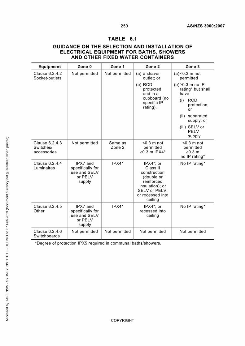
259 AS/NZS 3000:2007
COPYRIGHT
TABLE 6.1
GUIDANCE ON THE SELECTION AND INSTALLATION OF ELECTRICAL EQUIPMENT FOR BATHS, SHOWERS
AND OTHER FIXED WATER CONTAINERS
Equipment Zone 0 Zone 1 Zone 2 Zone 3
Clause 6.2.4.2 Socket-outlets
Not permitted Not permitted (a) a shaver outlet; or
(b) RCD-protected and in a cupboard (no specific IP rating).
(a) <0.3 m not permitted
(b) ≥0.3 m no IP rating* but shall have—
(i) RCD protection; or
(ii) separated supply; or
(iii) SELV or PELV supply
Clause 6.2.4.3 Switches/ accessories
Not permitted Same as Zone 2
<0.3 m not permitted
≥0.3 m IPX4*
<0.3 m not permitted
≥0.3 m no IP rating*
Clause 6.2.4.4 Luminaires
IPX7 and specifically for use and SELV
or PELV supply
IPX4* IPX4*; or Class II
construction (double or reinforced
insulation); or SELV or PELV; or recessed into
ceiling
No IP rating*
Clause 6.2.4.5 Other
IPX7 and specifically for use and SELV
or PELV supply
IPX4* IPX4*; or recessed into
ceiling
No IP rating*
Clause 6.2.4.6 Switchboards
Not permitted Not permitted Not permitted Not permitted
*Degree of protection IPX5 required in communal baths/showers.
Acc
esse
d by
TA
FE
NS
W -
SY
DN
EY
INS
TIT
UT
E -
ULT
IMO
on
07 F
eb 2
013
(Doc
umen
t cur
renc
y no
t gua
rant
eed
whe
n pr
inte
d)

AS/NZS 3000:2007 260
COPYRIGHT
= Zone 1
= Zone 2
= Zone 3
= Zone 0
LEGEND:
Zone 3
2.4
0.6
0.6
Zone 2
Zone 1
Zone 0
DIMENSIONS IN METRES
FIGURE 6.1 BATHS AND SHOWERS, ZONE DIMENSIONS (PLAN)— BATH WITHOUT SHOWER OR FIXED BARRIER
Acc
esse
d by
TA
FE
NS
W -
SY
DN
EY
INS
TIT
UT
E -
ULT
IMO
on
07 F
eb 2
013
(Doc
umen
t cur
renc
y no
t gua
rant
eed
whe
n pr
inte
d)

261 AS/NZS 3000:2007
COPYRIGHT
Zone 2
2.25
2.40.6
2.5 AZone 3Zone
1
Zone0
2.25 NZ
Zone 2
Zone 3
= Zone 1
= Zone 2
= Zone 3
= Zone 0
LEGEND:
DIMENSIONS IN METRES
FIGURE 6.2 BATHS AND SHOWERS, ZONE DIMENSIONS (ELEVATION)—BATH WITHOUT SHOWER OR FIXED BARRIER
Acc
esse
d by
TA
FE
NS
W -
SY
DN
EY
INS
TIT
UT
E -
ULT
IMO
on
07 F
eb 2
013
(Doc
umen
t cur
renc
y no
t gua
rant
eed
whe
n pr
inte
d)
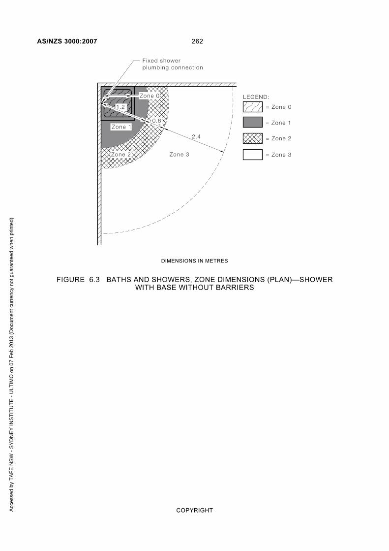
AS/NZS 3000:2007 262
COPYRIGHT
2.4
Zone 3
1.2
0.6
Zone 0
Zone 2
Fixed showerplumbing connect ion
Zone 1= Zone 1
= Zone 2
= Zone 3
= Zone 0
LEGEND:
DIMENSIONS IN METRES
FIGURE 6.3 BATHS AND SHOWERS, ZONE DIMENSIONS (PLAN)—SHOWER WITH BASE WITHOUT BARRIERS
Acc
esse
d by
TA
FE
NS
W -
SY
DN
EY
INS
TIT
UT
E -
ULT
IMO
on
07 F
eb 2
013
(Doc
umen
t cur
renc
y no
t gua
rant
eed
whe
n pr
inte
d)

263 AS/NZS 3000:2007
COPYRIGHT
= Zone 1
= Zone 2
= Zone 3
= Zone 0
LEGEND:
2.25
2.41.2 0.6
2.5 AZone 3
Zone 2
Zone 12.25 NZ
Fixed showerplumbingconnect ion
Zone 0
DIMENSIONS IN METRES
FIGURE 6.4 BATHS AND SHOWERS, ZONE DIMENSIONS (ELEVATION)—SHOWER WITH BASE WITHOUT BARRIERS
Acc
esse
d by
TA
FE
NS
W -
SY
DN
EY
INS
TIT
UT
E -
ULT
IMO
on
07 F
eb 2
013
(Doc
umen
t cur
renc
y no
t gua
rant
eed
whe
n pr
inte
d)

AS/NZS 3000:2007 264
COPYRIGHT
= Zone 1
= Zone 2
= Zone 3
= Zone 0
LEGEND:
Zone 3
Fixed par t i t ion
2.4
Zone 2Zone 2
0.6
Zone 0
Zone 1
b
b = width of bar r ie rr1 = 0.6 a b
r1r1
aa
DIMENSIONS IN METRES
FIGURE 6.5 BATHS AND SHOWERS, ZONE DIMENSIONS (PLAN)— BATH WITHOUT SHOWER WITH FIXED BARRIER
A1
Acc
esse
d by
TA
FE
NS
W -
SY
DN
EY
INS
TIT
UT
E -
ULT
IMO
on
07 F
eb 2
013
(Doc
umen
t cur
renc
y no
t gua
rant
eed
whe
n pr
inte
d)

265 AS/NZS 3000:2007
COPYRIGHT
Zone 0
1.2
0.6
2.4
Zone 3
Zone 1
Zone 2
= Zone 1
= Zone 2
= Zone 3
= Zone 0
LEGEND:
Fixed showerplumbing connect ion
0.6
DIMENSIONS IN METRES
FIGURE 6.6 BATHS AND SHOWERS, ZONE DIMENSIONS (PLAN)—BATH WITH SHOWER WITHOUT BARRIER
Acc
esse
d by
TA
FE
NS
W -
SY
DN
EY
INS
TIT
UT
E -
ULT
IMO
on
07 F
eb 2
013
(Doc
umen
t cur
renc
y no
t gua
rant
eed
whe
n pr
inte
d)

AS/NZS 3000:2007 266
COPYRIGHT
Barr ierBarr ie r
Zone 3
2.4
= Zone 1
= Zone 2
= Zone 3
= Zone 0
LEGEND:0.6
0.6
Zone 2
Zone 0
Fixed showerplumbing connect ionFixed showerplumbing connect ionFixed showerplumbing connect ionFixed showerplumbing connect ion
Zone 1
DIMENSIONS IN METRES
FIGURE 6.7 BATHS AND SHOWERS, ZONE DIMENSIONS (PLAN)—ENCLOSED SHOWER
A1
Acc
esse
d by
TA
FE
NS
W -
SY
DN
EY
INS
TIT
UT
E -
ULT
IMO
on
07 F
eb 2
013
(Doc
umen
t cur
renc
y no
t gua
rant
eed
whe
n pr
inte
d)

267 AS/NZS 3000:2007
COPYRIGHT
Zone 2
Zone 1 2.25
2.41.2 0.6
2.5 AZone 3
2.25 NZ1.8
Barr ier
F ixed showerplumbingconnect ion
= Zone 1
= Zone 2
= Zone 3
= Zone 0
LEGEND:
DIMENSIONS IN METRES
FIGURE 6.8 BATHS AND SHOWERS, ZONE DIMENSIONS (ELEVATION)—SHOWER WITH BARRIER
Acc
esse
d by
TA
FE
NS
W -
SY
DN
EY
INS
TIT
UT
E -
ULT
IMO
on
07 F
eb 2
013
(Doc
umen
t cur
renc
y no
t gua
rant
eed
whe
n pr
inte
d)

AS/NZS 3000:2007 268
COPYRIGHT
0.60.6
1.2
2.4
2.4
Zone 1 Zone 2
Zone 2
Zone 3
Zone 3
= Zone 2
= Zone 3
= Zone 1
LEGEND:
Fixed showerplumbing connect ion
Barr ier
DIMENSIONS IN METRES
FIGURE 6.9 BATHS AND SHOWERS, ZONE DIMENSIONS (PLAN)—PARTIALLY ENCLOSED SHOWER
A1
Acc
esse
d by
TA
FE
NS
W -
SY
DN
EY
INS
TIT
UT
E -
ULT
IMO
on
07 F
eb 2
013
(Doc
umen
t cur
renc
y no
t gua
rant
eed
whe
n pr
inte
d)

269 AS/NZS 3000:2007
COPYRIGHT
Zone 0
Zone 20.150.4
0.15
DIMENSIONS IN METRES
FIGURE 6.10 OTHER FIXED WATER CONTAINERS WITH A CAPACITY NOT EXCEEDING 45 L AND FIXED WATER OUTLETS, ZONE DIMENSIONS
Zone 0
Zone 2
0.5
1.0
0.5
DIMENSIONS IN METRES
FIGURE 6.11 OTHER FIXED WATER CONTAINERS WITH A CAPACITY EXCEEDING 45 L OR WITH A FLEXIBLE WATER OUTLET, ZONE DIMENSIONS
A1
A1
Acc
esse
d by
TA
FE
NS
W -
SY
DN
EY
INS
TIT
UT
E -
ULT
IMO
on
07 F
eb 2
013
(Doc
umen
t cur
renc
y no
t gua
rant
eed
whe
n pr
inte
d)

AS/NZS 3000:2007 270
COPYRIGHT
6.3 SWIMMING POOLS, PADDLING POOLS AND SPA POOLS OR TUBS
6.3.1 Scope
The particular requirements of this Clause 6.3 apply to electrical installations in locations containing swimming pools, paddling (wading) pools and spa pools or tubs and their surrounding zones where the risk of electric shock is increased by a reduction in body resistance and the likelihood of contact of the body with earth potential.
NOTE: For swimming pools for medical or large commercial use, special requirements may be necessary.
These requirements are based on the classification of zones surrounding the water container.
Ceilings, walls with or without windows, doors and floors, barriers and fixed partitions, e.g. a 1.8 m solid fence, that limit the extent of a room or area containing a swimming pool, paddling pool, spa pool or tub and fixed partitions that provide effective protection against spraying or splashing water, limit the associated zones.
Because of the nature of these locations certain methods of protection against electric shock are not permitted.
The requirements for swimming pools also apply to electrical installations in areas of natural waters, lakes in gravel pits and coastal and similar areas, especially those intended to be occupied by persons for swimming, paddling and similar purposes.
6.3.2 Classification of zones
6.3.2.1 Swimming pools and paddling pools
The following three zones (Zones 0, 1 and 2) are classified for swimming pools and paddling pools:
(a) Zone 0 shall be the area of the interior of the water container of a swimming pool or paddling pool.
(b) Zone 1 shall be the area limited by—
(i) Zone 0; and
(ii) a vertical plane 2.0 m from the internal rim of the water container; and
(iii) the floor, or surface expected to be occupied by persons; and
(iv) the horizontal plane 2.50 m above the floor or the surface; and
(v) when the pool contains a diving board, springboard, starting block or a slide, by the—
(A) vertical plane situated 1.50 m around the diving board, springboard, starting block or slide; and
(B) horizontal plane 2.50 m above the highest surface expected to be occupied by persons.
A1
Acc
esse
d by
TA
FE
NS
W -
SY
DN
EY
INS
TIT
UT
E -
ULT
IMO
on
07 F
eb 2
013
(Doc
umen
t cur
renc
y no
t gua
rant
eed
whe
n pr
inte
d)
271 AS/NZS 3000:2007
COPYRIGHT
(c) Zone 2 shall be the area limited by the—
(i) vertical plane limiting Zone 1 and the parallel vertical plane 1.50 m external to Zone 1; and
(ii) the floor, or surface expected to be occupied by persons, and the horizontal plane 2.50 m above the floor or surface.
Examples of these Zones are shown in Figures 6.12 to 6.14.
6.3.2.2 Spa pools or tubs
6.3.2.2.1 General
Spa pools or tubs with a water capacity not exceeding 500 L shall comply with the requirements of Clause 6.2.
A spa pool that is attached to a swimming or paddling pool shall be considered to be an extension to the swimming or paddling pool.
NOTE: Electrical equipment installed behind a fixed panel that provides degree of protection not less than IPX4, and to which access may only be gained by the use of a tool, would not be considered to be in a classified zone.
6.3.2.2.2 Water capacity exceeding 5000 L
The following three zones (Zones 0, 1 and 2) are classified for spa pools or tubs with a capacity exceeding 5000 L, as set out in Clause 6.3.2.1.
Examples of these zones are given in Figures 6.12 and 6.13.
6.3.2.2.3 Water capacity not exceeding 5000 L
The following two zones (Zones 0 and 1) are classified for spa pools and tubs with a capacity exceeding 500 L and up to and including 5000 L, as set out below:
(a) Zone 0 shall be the area of the interior of the water container.
(b) Zone 1 shall be the area limited by—
(i) the vertical plane 1.25 m from the internal rim of the water container; and
(ii) the floor, or the surface expected to be occupied by persons, and the horizontal plane 2.50 m above the floor or surface.
Examples of these zones are given in Figures 6.15 and 6.16.
6.3.3 Protection against electric shock
6.3.3.1 Prohibited measures
The following measures of protection against electric shock shall be prohibited:
(a) Protection by means of obstacles, in accordance with Clause 1.5.4.5.
(b) Protection by placing out of reach, in accordance with Clause 1.5.4.6.
Acc
esse
d by
TA
FE
NS
W -
SY
DN
EY
INS
TIT
UT
E -
ULT
IMO
on
07 F
eb 2
013
(Doc
umen
t cur
renc
y no
t gua
rant
eed
whe
n pr
inte
d)
AS/NZS 3000:2007 272
COPYRIGHT
6.3.3.2 Supplementary equipotential bonding
Where electrical equipment situated in a classified zone is required to be earthed, all extraneous conductive parts in Zones 0, 1 and 2 shall be connected together by equipotential bonding conductors and connected to the protective earthing conductor of the electrical equipment, in accordance with Clause 5.6.2.6.
6.3.3.3 Voltage gradients
Where electrical equipment is in contact with pool water, failure of insulation may result in a hazardous voltage appearing across or through the pool water. A very low voltage is sufficient to present a hazard to persons immersed in the water.
Protective measures may include—
(a) location of the electrical equipment at a distance from the pool with all plumbing connections being made of non-conductive materials; or
(b) metal grids or barriers inserted in any plumbing connections between the electrical equipment and pool and connected to the equipotential bonding system; or
(c) use of an RCD with a fixed rated residual current not exceeding 30 mA to protect circuits supplying Class I (earthed conductive parts) equipment.
6.3.4 Selection and installation of electrical equipment
6.3.4.1 Degree of protection required
Electrical equipment permitted to be installed in a classified zone shall have at least the following degree of protection:
(a) In Zone 0: IPX8.
(b) In Zone 1: IPX5.
(c) In Zone 2: IPX4.
NOTE: Guidance on the selection and installation of electrical equipment is provided in Table 6.2.
6.3.4.2 Wiring systems
Wiring systems shall be installed so as to prevent—
(a) entry of moisture to any connection; and
(b) water siphoning through any wiring enclosure or cable.
Bare aerial conductors shall not be installed over Zones 0, 1 or 2.
Other types of aerial cables shall be installed in accordance with Clause 3.12.
6.3.4.3 Socket-outlets
Socket-outlets shall not be installed within 0.3 m of any floor or any other horizontal surface in any location where the floor or surface is likely to become wet.
Acc
esse
d by
TA
FE
NS
W -
SY
DN
EY
INS
TIT
UT
E -
ULT
IMO
on
07 F
eb 2
013
(Doc
umen
t cur
renc
y no
t gua
rant
eed
whe
n pr
inte
d)

273 AS/NZS 3000:2007
COPYRIGHT
Regardless of the degree of protection provided by the equipment, the following conditions shall apply to the installation of socket-outlets in classified zones:
(a) Zone 0 Socket-outlets shall not be permitted in Zone 0.
(b) Zone 1 Socket-outlets not required for the connection of pool equipment shall not be permitted in Zone 1.
Socket-outlets necessary for the connection of pool equipment shall be permitted where:
(i) provided with the required degree of protection; and
(ii) located—
(A) at a height not less than 0.45 m above ground level and at a horizontal distance not less than 1.25 m from the internal rim of the water container; or
(B) beneath and not less than 0.5 m from the edge of a fixed continuous horizontal barrier that is not less than 1.25 m wide measured from the internal rim of the water container; and
(iii) either—
(C) supplied individually as a separated circuit, in accordance with Clause 7.4; or
(D) supplied as an SELV or a PELV system, in accordance with Clause 7.5; or
(E) protected by a residual-current device with a fixed rated residual current not exceeding 30 mA; and
(iv) controlled by a switch that requires manual operation and does not operate automatically by the insertion or withdrawal of a plug.
(c) Zone 2 Socket-outlets installed in Zone 2 shall be provided with the required degree of protection and—
(i) supplied individually as a separated circuit, in accordance with Clause 7.4; or
(ii) supplied as an SELV or a PELV system, in accordance with Clause 7.5; or
(iii) protected by an RCD with a fixed rated residual current not exceeding 30 mA.
6.3.4.4 Switches and other accessories
The following conditions shall apply to the installation of switches and accessories, other than socket-outlets, in classified zones:
(a) Zone 0 Switches and other accessories shall not be installed in Zone 0.
(b) Zone 1 and 2 Switches and other accessories installed in Zone 1 or Zone 2 shall be provided with the required degree of protection.
Acc
esse
d by
TA
FE
NS
W -
SY
DN
EY
INS
TIT
UT
E -
ULT
IMO
on
07 F
eb 2
013
(Doc
umen
t cur
renc
y no
t gua
rant
eed
whe
n pr
inte
d)

AS/NZS 3000:2007 274
COPYRIGHT
6.3.4.5 Luminaires, appliances and other electrical equipment
The following conditions shall apply to the installation of luminaires, appliances and other electrical equipment in classified zones:
(a) Zone 0 Luminaires, appliances and other electrical equipment shall be permitted in Zone 0 where—
(i) designed and constructed specifically for use in a swimming or spa pool; and
(ii) provided with the required degree of protection; and
(iii) each luminaire, appliance or other item of electrical equipment is supplied—
(A) from an individual source installed outside Zone 0; and
NOTE: An individual source may be an individual isolation transformer or an individual winding on an isolation transformer having a number of secondary windings, provided that the output complies with Clause 7.5.3.
(B) at a nominal voltage not exceeding 12 V a.c. or 30 V ripple-free d.c.; and
(C) as an SELV or a PELV system, in accordance with Clause 7.5.
Luminaires installed in Zone 0 shall not be provided with a protective earthing conductor, in accordance with Clause 5.4.3.
(b) Zone 1 Luminaires, appliances and other electrical equipment shall be permitted in Zone 1 where provided with the required degree of protection and—
(i) supplied as an SELV or a PELV system, in accordance with Clause 7.5; or
(ii) of Class II construction (double or reinforced insulation) and fixed in position; or
(iii) of Class I construction (earthed conductive parts), fixed in position and supplied from a circuit protected by an RCD with a fixed rated residual current not exceeding 30 mA.
(c) Zone 2 Luminaires, appliances and other electrical equipment shall be permitted in Zone 2 where provided with the required degree of protection and—
(i) supplied as an SELV or a PELV system, in accordance with Clause 7.5; or
(ii) supplied individually as a separated circuit, in accordance with Clause 7.4; or
(iii) of Class II construction (double or reinforced insulation); or
(iv) of Class I construction (earthed conductive parts) and supplied from a circuit protected by an RCD with a fixed rated residual current not exceeding 30 mA.
A1
A1
Acc
esse
d by
TA
FE
NS
W -
SY
DN
EY
INS
TIT
UT
E -
ULT
IMO
on
07 F
eb 2
013
(Doc
umen
t cur
renc
y no
t gua
rant
eed
whe
n pr
inte
d)

275 AS/NZS 3000:2007
COPYRIGHT
(d) Zones 1 and 2 Heating cable systems intended for heating the location and that are embedded in the floor and protected in accordance with Clause 4.10 shall be permitted.
NOTE: The use of a purpose made pump and installation to the manufacturers’ instructions complying with the requirements of AS/NZS 60335.2.41 for each zone is deemed to comply with the requirements of this clause.
6.3.4.6 Switchboards
A switchboard shall not be installed within any classified zone.
A1
Acc
esse
d by
TA
FE
NS
W -
SY
DN
EY
INS
TIT
UT
E -
ULT
IMO
on
07 F
eb 2
013
(Doc
umen
t cur
renc
y no
t gua
rant
eed
whe
n pr
inte
d)

AS/NZS 3000:2007 276
COPYRIGHT
TABLE 6.2
GUIDANCE ON THE SELECTION AND INSTALLATION
OF ELECTRICAL EQUIPMENT FOR SWIMMING POOLS, PADDLING POOLS AND SPA
POOLS OR TUBS
Equipment Zone 0 Zone 1 Zone 2
Clause 6.3.4.3 Socket – Outlets
Not permitted Not permitted for general use.
For pool equipment only—
(i) IPX5; and
(ii) (A) ≥0.45 m high; and ≥1.25 m from internal rim; or
(B) under and ≥0.5 m from edge of fixed continuous horizontal barrier ≥1.25 m wide; and
(iii) (A) separated supply; or
(B) SELV or PELV supply; or
(C) RCD protection
IPX4; and
(i) separated supply; or
(ii) SELV or PELV supply; or
(iii) RCD protection
Clause 6.3.4.4 Switches/ accessories
Not permitted IPX5 IPX4
Clause 6.3.4.5 (a), (b) and (c) Appliances, Luminaires and other equipment
IPX8; and specifically for use; and 12V a.c./30 V d.c. SELV or PELV supply from source outside zone
No earth
IPX5; and
(i) SELV or PELV supply; or
(ii) Class II construction (double or reinforced insulation); or
(iii) Class I construction (earthed conductive parts), fixed in position and RCD protection
IPX4; and
(i) SELV or PELV supply; or
(ii) Separated supply; or
(iii) Class II construction (double or reinforced insulation); or
(iv) Class I construction (earthed conductive parts), and RCD protection
Clause 6.3.4.5 (d) Heating cable systems
Not applicable Permitted where embedded in the floor area under the Zone and protected to Clause 4.10.5
As for Zone 1
Clause 6.3.4.6 Switchboards
Not permitted Not permitted Not permitted
A1
Acc
esse
d by
TA
FE
NS
W -
SY
DN
EY
INS
TIT
UT
E -
ULT
IMO
on
07 F
eb 2
013
(Doc
umen
t cur
renc
y no
t gua
rant
eed
whe
n pr
inte
d)
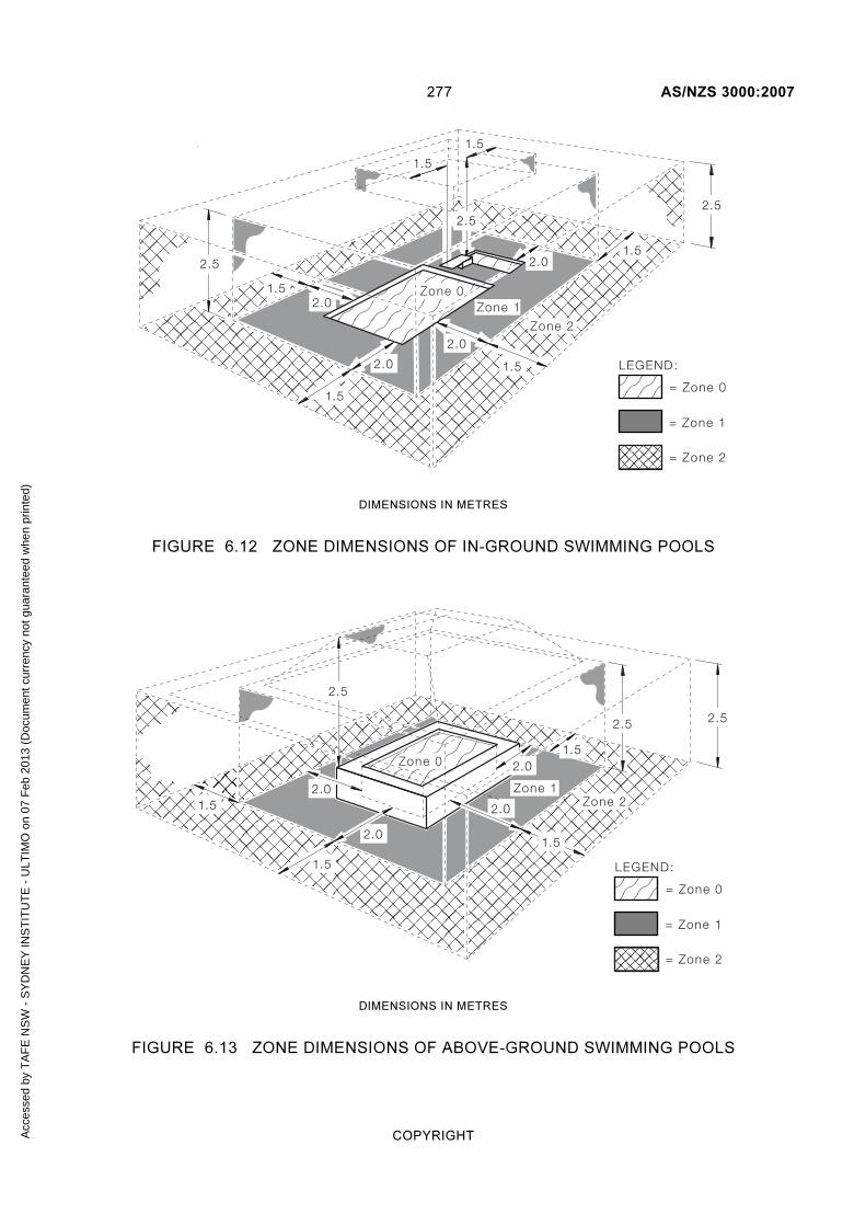
277 AS/NZS 3000:2007
COPYRIGHT
= Zone 1
= Zone 2
= Zone 0
1.52.0
2.0
2.0
1.5
1.5
1.5
1.5
1.5
2.0
LEGEND:
2.5
2.52.5
Zone 1
Zone 2
Zone 0
DIMENSIONS IN METRES
FIGURE 6.12 ZONE DIMENSIONS OF IN-GROUND SWIMMING POOLS
= Zone 1
= Zone 2
= Zone 0
2.0
2.0
1.5
1.5
2.01.5
2.0
2.52.5
2.5
1.5
LEGEND:
Zone 1Zone 2
Zone 0
DIMENSIONS IN METRES
FIGURE 6.13 ZONE DIMENSIONS OF ABOVE-GROUND SWIMMING POOLS
Acc
esse
d by
TA
FE
NS
W -
SY
DN
EY
INS
TIT
UT
E -
ULT
IMO
on
07 F
eb 2
013
(Doc
umen
t cur
renc
y no
t gua
rant
eed
whe
n pr
inte
d)

AS/NZS 3000:2007 278
COPYRIGHT
1.5
2.0 Zone 1
Zone 2
r2
r3
r1
r1
R 3.5
R 2.0
a
R 2.0
s1s2 r4r5
R 2.0
R 3.5
b
LEGEND:
r1 = 2.0 as1 = Width of barr ier 1r2 = r1 s1s2 = Width of barr ier 2r3 = 3.5 ar4 = 3.5 br5 = r4 s2
= Zone 1
= Zone 2
= Zone 0
Zone 0
Barr ier 1
Barr ier 2
DIMENSIONS IN METRES
FIGURE 6.14 ZONE DIMENSIONS OF SWIMMING POOLS WITH FIXED BARRIERS (MINIMUM 1.8 M HIGH)
NOTE:These dimensions apply to swimming pools, paddling pools and wading pools.
Acc
esse
d by
TA
FE
NS
W -
SY
DN
EY
INS
TIT
UT
E -
ULT
IMO
on
07 F
eb 2
013
(Doc
umen
t cur
renc
y no
t gua
rant
eed
whe
n pr
inte
d)

279 AS/NZS 3000:2007
COPYRIGHT
1.25
1.25
= Zone 1
= Zone 0
1.25
1.25
2.5
2.5
LEGEND:
Zone 1Zone 0
DIMENSIONS IN METRES
FIGURE 6.15 ZONE DIMENSIONS OF IN-GROUND SPA POOLS AND TUBS WITH WATER CAPACITY NOT EXCEEDING 5000 L
Acc
esse
d by
TA
FE
NS
W -
SY
DN
EY
INS
TIT
UT
E -
ULT
IMO
on
07 F
eb 2
013
(Doc
umen
t cur
renc
y no
t gua
rant
eed
whe
n pr
inte
d)

AS/NZS 3000:2007 280
COPYRIGHT
2.5
1.25
1.25
= Zone 1
= Zone 0
1.25
1.25
2.5
2.5
LEGEND:
Zone 1
Zone 0
DIMENSIONS IN METRES
FIGURE 6.16 ZONE DIMENSIONS OF ABOVE-GROUND SPA POOLS AND TUBS WITH WATER CAPACITY NOT EXCEEDING 5000 L
6.4 FOUNTAINS AND WATER FEATURES
6.4.1 Scope
The particular requirements of this Clause 6.4 apply to the electrical installations associated with water containers of fountains and water features and their surrounding zones where the risk of electric shock is increased by a reduction in body resistance and the likelihood of contact of the body with earth potential.
These requirements are based on the classification of zones surrounding the water container associated with the fountain or water feature and are intended to—
(a) protect electrical material and electrical equipment from the corrosive effects of chemicals used in the treatment of water in fountains and water features; and
(b) counter the increased risks of using electrical equipment in areas where the body may be partially immersed in water.
These requirements need not apply to fountains or water features where—
(i) the depth of water does not exceed 0.3 m; or
Acc
esse
d by
TA
FE
NS
W -
SY
DN
EY
INS
TIT
UT
E -
ULT
IMO
on
07 F
eb 2
013
(Doc
umen
t cur
renc
y no
t gua
rant
eed
whe
n pr
inte
d)

281 AS/NZS 3000:2007
COPYRIGHT
(ii) suitable means are provided to restrict entry of persons to the water.
Ceilings, walls with or without windows, doors and floors that limit the extent of a room or area containing a fountain or water feature and fixed partitions that provide effective protection against spraying or splashing water, limit the associated zones.
Because of the nature of these locations certain methods of protection against electric shock are not permitted.
6.4.2 Classification of zones
The following two zones (Zones 0 and 1) are classified for fountains and water features:
(a) Zone 0 shall be the area of the interior of the water containers including any recesses in their walls or floors or the interior of water jets or waterfalls.
(b) Zone 1 shall be the area limited—
(i) by the vertical plane 2.0 m from the internal rim of the water containers; and
(ii) by the floor, or surface expected to be occupied by persons, and the horizontal plane 2.50 m above the floor or surface; and
(iii) when the fountain or water feature contains sculptures and decorative water containers, by the—
(A) vertical plane situated 1.50 m around the sculptures and decorative water containers; and
(B) horizontal plane 2.50 m above the sculptures and decorative water containers.
Examples of these Zones are shown in Figures 6.17 and 6.18.
6.4.3 Protection against electric shock
6.4.3.1 Use of SELV
Where SELV is used, regardless of the nominal voltage, basic protection shall be provided in accordance with Clause 7.5.5.
6.4.3.2 Application of protective measures against electric shock
6.4.3.2.1 Supply
Electrical equipment shall be—
(a) earthed and protected by an RCD with a fixed rated residual current not exceeding 30 mA; or
(b) supplied at either extra-low voltage or low voltage through an isolating transformer complying with AS/NZS 61558, and not earthed; or
(c) supplied by other suitable measures that take account of the electrical equipment construction, installation methods and physical location.
Acc
esse
d by
TA
FE
NS
W -
SY
DN
EY
INS
TIT
UT
E -
ULT
IMO
on
07 F
eb 2
013
(Doc
umen
t cur
renc
y no
t gua
rant
eed
whe
n pr
inte
d)

AS/NZS 3000:2007 282
COPYRIGHT
6.4.3.2.2 Prohibited measures
The following measures of protection against electric shock shall be prohibited:
(a) Protection by means of obstacles, in accordance with Clause 1.5.4.5.
(b) Protection by placing out of reach, in accordance with Clause 1.5.4.6.
6.4.4 Selection and installation of electrical equipment
6.4.4.1 Degree of protection required
Electrical equipment permitted to be installed in the classified zone, shall have at least the following degree of protection:
(a) In Zone 0: IPX8.
(b) In Zone 1: IPX5.
6.4.4.2 Wiring systems
Wiring systems for a fountain or water feature shall be—
(a) elastomer or thermoplastic insulated and sheathed copper cables or flexible cords suitable for immersion in the type of water being used; and
(b) where subject to mechanical damage, installed in a wiring enclosure; and
(c) installed so as to prevent—
(i) entry of moisture to any connection; and
(ii) water siphoning through any wiring enclosure or cable.
6.4.4.3 Socket-outlets
Socket-outlets shall not be permitted in Zone 0 or Zone 1.
6.4.4.4 Switches and other accessories
The following conditions shall apply to the installation of switches and accessories, other than socket-outlets, in classified zones:
(a) Zone 0 Switches and other accessories shall not be installed in Zone 0.
(b) Zone 1 Switches and other accessories installed in Zone 1 shall be provided with the required degree of protection.
6.4.4.5 Luminaires, appliances and other electrical equipment
The following conditions shall apply to the installation of luminaires, appliances and other electrical equipment in classified zones:
(a) Zone 0 Luminaires, appliances and other electrical equipment shall be permitted in Zone 0 where—
(i) designed and constructed specifically for use in a fountain or water feature; and
(ii) provided with the required degree of protection; and
Acc
esse
d by
TA
FE
NS
W -
SY
DN
EY
INS
TIT
UT
E -
ULT
IMO
on
07 F
eb 2
013
(Doc
umen
t cur
renc
y no
t gua
rant
eed
whe
n pr
inte
d)

283 AS/NZS 3000:2007
COPYRIGHT
(iii) each luminaire, appliance or other item of electrical equipment is supplied—
(A) from an individual source installed outside Zone 0; and
NOTE: An individual source may be an individual isolation transformer or an individual winding on an isolation transformer having a number of secondary windings, provided that the output complies with Clause 7.5.3.
(B) at a nominal voltage not exceeding 12 V a.c. or 30 V ripple-free d.c.; and
(C) as an SELV or a PELV system, in accordance with Clause 7.5.
Luminaires installed in Zone 0 shall not be provided with a protective earthing conductor in accordance with Clause 5.4.3.
(b) Zone 1 Luminaires, appliances and other electrical equipment shall be permitted in Zone 1, where provided with the required degree of protection and—
(i) supplied as an SELV or a PELV system, in accordance with Clause 7.5; or
(ii) of Class II construction (double or reinforced insulation) and fixed in position; or
(iii) of Class I construction (earthed conductive parts), fixed in position and supplied from a circuit protected by an RCD with a fixed rated residual current not exceeding 30 mA.
NOTE: The use of a purpose made pump and installation to the manufacturers’ instructions complying with the requirements of AS/NZS 60335.2.41 for the relevant zone is deemed to comply with the requirements of this Clause 6.4.4.5.
6.4.4.6 Switchboards
A switchboard shall not be installed within any classified zone.
A1
A1
A1
Acc
esse
d by
TA
FE
NS
W -
SY
DN
EY
INS
TIT
UT
E -
ULT
IMO
on
07 F
eb 2
013
(Doc
umen
t cur
renc
y no
t gua
rant
eed
whe
n pr
inte
d)

AS/NZS 3000:2007 284
COPYRIGHT
Zone 0
2.0
2.0
2.0
Zone 1 Zone 0
Zone 0Zone 1
2.0
= Zone 1
= Zone 0
LEGEND:
DIMENSIONS IN METRES
FIGURE 6.17 EXAMPLE OF DETERMINATION OF THE ZONES OF A FOUNTAIN (PLAN)
Acc
esse
d by
TA
FE
NS
W -
SY
DN
EY
INS
TIT
UT
E -
ULT
IMO
on
07 F
eb 2
013
(Doc
umen
t cur
renc
y no
t gua
rant
eed
whe
n pr
inte
d)

285 AS/NZS 3000:2007
COPYRIGHT
= Water in Zone 0
= Zone 1
LEGEND:
Zone 1= L imi t of Zone 0
2.0
1.5
1.5
1.5
2.0
2.52.5
2.5
2.5
Basin
Pool
2.5
Zone 0
DIMENSIONS IN METRES
FIGURE 6.18 EXAMPLE OF DETERMINATION OF THE ZONES OF A FOUNTAIN (ELEVATION)
6.5 SAUNAS
6.5.1 Scope
The particular requirements of this Clause 6.5 apply to electrical installations in rooms or enclosures containing heating equipment used exclusively for sauna heating.
These requirements are based on the classification of zones surrounding the sauna heater. Because of the nature of these locations certain methods of protection against electric shock are not permitted.
6.5.2 Classification of zones
The following three zones (Zones 1, 2 and 3) are classified for locations containing a sauna heater:
(a) Zone 1 shall be the area containing the sauna heater limited by the—
(i) vertical plane 0.5 m from the external edge of the sauna heater; and
(ii) floor, or surface expected to be occupied by persons, and the cold side of the thermal insulation of the ceiling.
(b) Zone 2 shall be the area limited by the—
(i) vertical plane limiting Zone 1 and the cold side of the thermal insulation of the walls of the sauna room or enclosure; and
(ii) floor, or surface expected to be occupied by persons, and the horizontal plane 1.0 m above the floor.
Acc
esse
d by
TA
FE
NS
W -
SY
DN
EY
INS
TIT
UT
E -
ULT
IMO
on
07 F
eb 2
013
(Doc
umen
t cur
renc
y no
t gua
rant
eed
whe
n pr
inte
d)

AS/NZS 3000:2007 286
COPYRIGHT
(c) Zone 3 shall be the area limited by the—
(i) vertical plane limiting Zone 1 and the cold side of the thermal insulation of the walls of the sauna room or enclosure; and
(ii) horizontal plane 1.0 m above the floor and the cold side of the thermal insulation of the ceiling.
NOTE: Zone 3 is directly above Zone 2.
NOTE: Examples of these Zones are given in Figure 6.19.
6.5.3 Protection against electric shock
6.5.3.1 Use of SELV
Where SELV is used, regardless of the nominal voltage, basic protection shall be provided in accordance with Clause 7.5.5.
6.5.3.2 Prohibited measures
The following measures of protection against electric shock shall be prohibited:
(a) Protection by means of obstacles, in accordance with Clause 1.5.4.5
(b) Protection by placing out of reach, in accordance with Clause 1.5.4.6
6.5.3.3 Additional protection by RCD
All equipment within the sauna room, other than the sauna heater, shall be provided with additional protection by an RCD with a fixed rated residual current not exceeding 30 mA.
6.5.4 Selection and installation of electrical equipment
6.5.4.1 Degree of protection required
Electrical equipment installed within the sauna room shall have a degree of protection of at least IPX4B or IP24.
6.5.4.2 Requirements in classified zones
The installation of electrical equipment and wiring in classified zones shall be in accordance with the following:
(a) Zone 1 Only electrical equipment belonging to the sauna heater shall be permitted.
(b) Zone 2 There are no special requirements concerning heat resistance of electrical equipment.
(c) Zone 3 Electrical equipment shall be suitable to withstand a minimum temperature of 125°C and the insulation of conductors shall be suitable to withstand a minimum temperature of 170°C.
Acc
esse
d by
TA
FE
NS
W -
SY
DN
EY
INS
TIT
UT
E -
ULT
IMO
on
07 F
eb 2
013
(Doc
umen
t cur
renc
y no
t gua
rant
eed
whe
n pr
inte
d)

287 AS/NZS 3000:2007
COPYRIGHT
6.5.4.3 Wiring systems
Wiring systems should be installed outside the zones, i.e. on the cold side of the thermal insulation. If the wiring system is installed in Zone 1 or 3, i.e. on the warm side of the thermal insulation, it shall be heat-resistant, in accordance with Clause 6.5.4.2(c). Metallic sheaths and metallic conduits shall not be accessible in normal use.
NOTE: Examples of suitable wiring systems are insulated, unsheathed cables in non-metallic enclosures or sheathed cables.
6.5.4.4 Socket-outlets, switches and other accessories
Socket-outlets, switches and other accessories shall not be installed within a sauna room or enclosure.
Exception: Switches and other accessories that form part of the sauna heater may be located within the sauna room or enclosure.
6.5.4.5 Other equipment
Sauna heating appliances shall be installed in accordance with the manufacturer’s instructions.
6.5.4.6 Switchboards
A switchboard shall not be installed within any classified zone.
Acc
esse
d by
TA
FE
NS
W -
SY
DN
EY
INS
TIT
UT
E -
ULT
IMO
on
07 F
eb 2
013
(Doc
umen
t cur
renc
y no
t gua
rant
eed
whe
n pr
inte
d)

AS/NZS 3000:2007 288
COPYRIGHT
1.0
Zone 3
(a ) E levat ion
Connect ionbox
Thermal insu lat ion
Thermal insu lat ion
(b ) Plan
Zone 1
Zone 1
0.5
0.5
Zone 2
Zone 3 above Zone 2
= Zone 2
= Zone 3
= Zone 1
LEGEND:
FIGURE 6.19 CLASSIFIED ZONES FOR SAUNA HEATERS
Acc
esse
d by
TA
FE
NS
W -
SY
DN
EY
INS
TIT
UT
E -
ULT
IMO
on
07 F
eb 2
013
(Doc
umen
t cur
renc
y no
t gua
rant
eed
whe
n pr
inte
d)
289 AS/NZS 3000:2007
COPYRIGHT
6.6 REFRIGERATION ROOMS
6.6.1 Scope
The particular requirements of this Clause 6.6 apply to locations, such as freezers or cold rooms. Because of the nature of these locations certain methods of protection against electric shock are not permitted.
6.6.2 Classification of zone
A single zone that comprises all of the area within the refrigeration room is classified for refrigerated rooms.
6.6.3 Protection against electric shock
6.6.3.1 Use of SELV
Where SELV is used, whatever the nominal voltage, basic protection shall be provided in accordance with Clause 7.5.5.
6.6.3.2 Prohibited measures
The following measures of protection against electric shock shall be prohibited:
(a) Protection by means of obstacles, in accordance with Clause 1.5.4.5.
(b) Protection by placing out of reach, in accordance with Clause 1.5.4.6.
6.6.4 Selection and installation of electrical equipment
6.6.4.1 Degree of protection required
Electrical equipment permitted to be installed within the refrigeration room shall have a degree of protection of at least IPX4B or IP24.
NOTE: See also Clause 6.7 regarding areas that are subjected to a sanitization or hosing-down process.
6.6.4.2 Wiring systems
6.6.4.2.1 General
The wiring system used for the supply, control and protection of electrical equipment within a refrigeration room shall be of a type that—
(a) will not be affected by the operating temperature of the room; and
(b) does not provide pockets or channels in which moisture might accumulate, or through which it might pass into electrical equipment.
Wiring systems not associated with the refrigeration room electrical equipment shall not be taken through, or be installed, in such rooms.
6.6.4.2.2 Types permitted
The following wiring systems are permitted:
(a) Unenclosed sheathed cables including served MIMS cables.
(b) Insulated, unsheathed or sheathed cables enclosed in a wiring enclosure that has adequate draining facilities.
(c) Other wiring systems that are not inferior to the systems described in Item (a) or Item (b).
Acc
esse
d by
TA
FE
NS
W -
SY
DN
EY
INS
TIT
UT
E -
ULT
IMO
on
07 F
eb 2
013
(Doc
umen
t cur
renc
y no
t gua
rant
eed
whe
n pr
inte
d)

AS/NZS 3000:2007 290
COPYRIGHT
NOTE: PVC insulated, unsheathed or sheathed cables may not be satisfactory for electrical installations in refrigerated rooms where the cables may be subjected to bending, flexing or vibration at temperatures below approximately 0°C. See Clause 3.3.2.1 and Table 3.2.
6.6.4.2.3 Sealing
The following shall be sealed with a compound that does not set hard:
(a) Each wiring enclosure at any point where it passes from a refrigerated to a non-refrigerated space.
(b) The point of entry of cables into motors, luminaires, switches or other electrical equipment.
6.6.4.3 Socket-outlets, switches and other accessories
Socket-outlets, switches and other accessories shall be designed such that provision is made to prevent the retention of moisture within their enclosure.
This requirement may be satisfied by the use of socket-outlets, switches and other accessories, and controlgear having the required degree of protection, in accordance with Clause 6.6.4.1, or Clause 6.7, as appropriate, that are permanently sealed.
6.6.4.4 Luminaires and lampholders
6.6.4.4.1 Luminaires
Luminaires shall be permanently sealed to prevent the entry of liquid or vapour, or shall be designed and constructed so that—
(a) moisture cannot enter the lampholder and other components containing live parts; and
(b) provision is made to prevent the retention of moisture in or on the fitting.
6.6.4.4.2 Lampholders
Lampholders shall comply with the following:
(a) Construction Lampholders shall be—
(i) the all-insulated type; or
(ii) any other suitable type that precludes the possibility of any external metal portion becoming live.
(b) Location Lampholders shall not be suspended within 2.50 m of the floor or ground when on a flexible pendant.
6.6.4.5 Fixed appliances and motors
Fixed appliances shall be designed and constructed for the particular location and conditions.
Electrical equipment enclosures shall have, or provide, a degree of protection suitable for the conditions in which the electrical equipment is installed.
Acc
esse
d by
TA
FE
NS
W -
SY
DN
EY
INS
TIT
UT
E -
ULT
IMO
on
07 F
eb 2
013
(Doc
umen
t cur
renc
y no
t gua
rant
eed
whe
n pr
inte
d)

291 AS/NZS 3000:2007
COPYRIGHT
This requirement shall be deemed to be satisfied by the provision of internal heaters in the appliance or enclosure that would prevent the retention of moisture.
6.6.4.6 Heating elements in door seals
Heating elements in refrigeration room door seals shall be provided with additional protection by an RCD with a fixed rated residual current not exceeding 30 mA.
6.6.4.7 Switchboards
A switchboard shall not be installed in a refrigeration room.
6.7 SANITIZATION AND GENERAL HOSING-DOWN OPERATIONS
6.7.1 Scope
The particular requirements of this Clause 6.7 apply to electrical installations where sanitization or general hosing-down operations are carried out.
Because of the nature of these locations certain methods of protection against electric shock are not permitted.
NOTE: Electrical installations where the requirements of this Clause may apply include, without limitation, food production or processing areas and agricultural or horticultural premises, such as rooms, locations or areas where—
(a) livestock are kept; or
(b) feed, fertilizers, vegetable or animal products are produced stored, prepared or processed; or
(c) plants are grown, such as greenhouses or hydroponic installations; or
(d) agricultural or horticultural products are produced, prepared or processed, e.g. dairies, drying, stewing, pressing out, fermenting, butchering, meat processing, etc; or
(e) car wash bays and the like.
6.7.2 Classification of zone
The classified zone is based on the dimensions and limits of any location likely to be affected by hosing, as follows:
(a) Where the area is to be sanitized or hosed down throughout, the classified zone consists of the whole of the space between the floor, walls and ceiling, including any recess therein, enclosing the area.
(b) Where hosing-down is limited to the floor and walls, the classified zone consists of—
(i) any location within the space from the floor, or the base of a recess in the floor, to a horizontal plane 2.0 m above the floor; and
(ii) any wall within the area; and
(iii) any location on a ceiling that is within 1.0 m of a wall within the area.
A1
Acc
esse
d by
TA
FE
NS
W -
SY
DN
EY
INS
TIT
UT
E -
ULT
IMO
on
07 F
eb 2
013
(Doc
umen
t cur
renc
y no
t gua
rant
eed
whe
n pr
inte
d)

AS/NZS 3000:2007 292
COPYRIGHT
(c) Where hosing-down is limited to the floor only, the classified zone consists of any location within the space from the floor, or the base of a recess in the floor, to a horizontal plane 1.0 m above the floor.
6.7.3 Protection against electric shock
6.7.3.1 Use of SELV
Where SELV is used, whatever the nominal voltage, basic protection shall be provided in accordance with Clause 7.5.5.
6.7.3.2 Prohibited measures
The following measures of protection against electric shock shall be prohibited:
(a) Protection by means of obstacles, in accordance with Clause 1.5.4.5.
(b) Protection by placing out of reach, in accordance with Clause 1.5.4.6.
6.7.4 Selection and installation of electrical equipment
6.7.4.1 General
Electrical equipment installed within the classified zone shall be selected and installed to be suitable for the temperature and pressure of the fluids used in the hosing-down or sanitization process.
Electrical equipment installed in an area subject to sanitization processes shall be selected to be suitable where exposed to the relevant chemicals used in that process in accordance with Clause 3.3.
6.7.4.2 Degree of protection required
In addition to the requirements of Clause 6.7.4.1, electrical equipment installed within the classified zone shall have a degree of protection of at least—
(a) IPX5 where low or medium pressure hosing-down is used; and
(b) IPX6 where high pressure hosing is used.
6.7.4.3 Electrical equipment
Electrical equipment, including the wiring system, used in the classified zone shall be of a type that—
(a) will not be affected by the method of hosing, materials used, temperature and pressure of the hosing medium; and
(b) is protected against moisture that might accumulate; and
(c) does not provide channels or pockets through which moisture might pass into electrical equipment.
6.7.4.4 Switchboards
Switchboards installed in classified zones in locations subject to sanitization or hosing-down operations shall be provided with a minimum degree of protection of IPX6.
Acc
esse
d by
TA
FE
NS
W -
SY
DN
EY
INS
TIT
UT
E -
ULT
IMO
on
07 F
eb 2
013
(Doc
umen
t cur
renc
y no
t gua
rant
eed
whe
n pr
inte
d)

293 AS/NZS 3000:2007
COPYRIGHT
S E C T I O N 7 S P E C I A L E L E C T R I C A L
I N S T A L L A T I O N S
7.1 GENERAL
7.1.1 Application
The provisions of Section 7 form the minimum standard in relation to the selection and installation of electrical equipment in special electrical installations that must be achieved to satisfy Part 1 of this Standard.
7.1.2 Selection and installation
The particular requirements for each special electrical installation replace or modify the general requirements of the other Sections of this Standard. Where this Section does not specify a requirement, the relevant requirements of other Sections of this Standard apply.
This Section 7 relates to the following special electrical installations:
(a) Electrical systems for safety services.
(b) Electricity generation systems.
(c) Protection by electrical separation.
(d) Extra-low voltage electrical installations.
(e) High voltage electrical installations.
(f) Installations in areas where an explosive hazard may arise.
(g) Electrical installations of—
(i) construction and demolition sites; and
(ii) electromedical treatment areas; and
(iii) relocatable installations and the sites from which they are supplied; and
(iv) marinas and recreational boats; and
(v) shows and carnivals; and
(vi) cold cathode illumination systems; and
(vii) telecommunication networks power supplies; and
(viii) cranes and hoists; and
(ix) lifts; and
(x) generating sets; and
(xi) outdoor sites under heavy conditions; and
(xii) electric fences; and
(xiii) film, video and television sites.
Acc
esse
d by
TA
FE
NS
W -
SY
DN
EY
INS
TIT
UT
E -
ULT
IMO
on
07 F
eb 2
013
(Doc
umen
t cur
renc
y no
t gua
rant
eed
whe
n pr
inte
d)

AS/NZS 3000:2007 294
COPYRIGHT
7.2 SAFETY SERVICES
7.2.1 Scope
7.2.1.1 General
The particular requirements of this Clause 7.2 apply to the electrical installation of building services that are essential for the safe operation of the safety services consisting of fire detection, warning and extinguishing systems, smoke control systems, evacuation systems and the safety of persons using lifts.
The requirements are intended to ensure that electricity supply is not inadvertently disconnected from electrical equipment that is required to operate during emergency conditions.
NOTES:
1 AS/NZS 3009 provides guidance for emergency power supplies in hospitals.
2 The term ‘safety services’ incorporates equipment—
(a) described and which may be labelled, as “emergency systems” under the previous edition of this Standard; and
(b) determined as “emergency equipment” in the Building Code of Australia and “essential service” in the New Zealand Building Code.
7.2.1.2 Fire- and smoke-control equipment
For the purposes of this Clause 7.2, fire- and smoke-control equipment shall be deemed to include the following items and electrical equipment that are essential to their safe operation:
(a) Fire hydrant booster pumps.
(b) Pumps for automatic sprinkler systems, water spray or deluge systems and similar fire-extinguishing systems.
(c) Pumps for fire-hose reels, where such hose reels form the sole means of fire protection, i.e. where fire hydrants and automatic fire-sprinkler systems are not installed.
(d) Fire detection and alarm systems.
(e) Air-handling systems intended to exhaust and control the spread of fire and smoke.
Exception: The requirements of this Section need not apply to electrical equipment the failure of which does not affect the operation of safety services.
Examples include the following:
(i) Pumps for ‘jacking’ or water pressure maintenance, the failure of which does not deprive the fire hydrant or sprinkler pump of adequate water supply.
(ii) Pumps for fire-hose reels, where the hose reels are not the only fire-extinguishing system within a building, e.g. when used with a sprinkler system.
A2
Acc
esse
d by
TA
FE
NS
W -
SY
DN
EY
INS
TIT
UT
E -
ULT
IMO
on
07 F
eb 2
013
(Doc
umen
t cur
renc
y no
t gua
rant
eed
whe
n pr
inte
d)

295 AS/NZS 3000:2007
COPYRIGHT
(iii) Smoke alarms installed in single private residences, (see Clause 4.6 for information relating to smoke alarms).
NOTE: Attention is drawn to the requirements for—
(a) fire pumps in the AS 2118 series, AS 2419.1 and AS 2941 or NZS 4515, NZS 4517 and NZS 4541; and
(b) automatic sprinkler systems in the AS 2118 series or NZS 4541; and
(c) fire detection, alarm and intercom systems in AS 1670 or NZS 4512; and
(d) air-handling systems in AS/NZS 1668.1.
Although compliance with the Standards listed in Items (a) to (d) is not a requirement of this Standard, regulatory authorities may require compliance and may have additional requirements including requirements of National Building Codes.
7.2.1.3 Evacuation equipment
For the purposes of this Clause 7.2, evacuation equipment shall be deemed to include the following:
(a) Sound systems and intercom systems for emergency purposes.
(b) Central system emergency evacuation lighting complying with the AS or AS/NZS 2293 series.
NOTE: Attention is drawn to the requirements for—
(a) sound systems and intercom systems for emergency purposes in the AS 1670 series; and
(b) emergency evacuation lighting in the AS or AS/NZS 2293 series.
Although compliance with the Standards listed in Items (a) and (b) is not a
requirement of this Standard, regulatory authorities may require compliance
and may have additional requirements.
7.2.1.4 Lifts
For the purposes of this Clause 7.2, lifts shall be deemed to include electrically controlled lifts that may convey persons, but do not include any conveying device from which passengers may safely alight should the apparatus stop at any point in its travel (for example escalators).
Exceptions:
1 The electricity supply for a passenger lift that allows passengers to alight safely in the event of a loss of electricity supply need not be arranged as a safety service (for example, hydraulic or other lifts incorporating means for evacuation to a floor level).
2 A lift in a single private residence that is installed in accordance with AS/NZS 1735.18 need not comply with the requirements of this Clause 7.2.
NOTE: Although compliance with the AS 1735 series is not a requirement of this Standard, regulatory authorities may require compliance and may have additional requirements.
A1
A2
A2
Acc
esse
d by
TA
FE
NS
W -
SY
DN
EY
INS
TIT
UT
E -
ULT
IMO
on
07 F
eb 2
013
(Doc
umen
t cur
renc
y no
t gua
rant
eed
whe
n pr
inte
d)

AS/NZS 3000:2007 296
COPYRIGHT
7.2.2 Supply systems
7.2.2.1 Separation of supplies
Each part of an electrical installation supplying a safety service shall be controlled by a main switch or switches, separate from those used to control the remainder of the electrical installation, in accordance with Clauses 7.2.3 and 7.2.4.
Circuits for safety services shall be separate from those used to supply the remainder of the electrical installation.
An electrical source for safety services may be used for purposes other than safety services only if the availability for safety services is not impaired.
NOTE: When safety services are required, it may be necessary to disconnect supply to other equipment.
7.2.2.2 Discrimination of circuit-protective devices
Protective devices shall be selected such that—
(a) a fault on one safety service will not result in loss of supply to other safety services; and
(b) a fault on the general electrical installation will not result in loss of supply to safety services.
Fault-current limiters used to protect safety services shall not be used to provide protection to any part of the general electrical installation.
NOTE: This discrimination is intended to apply only up to the level of an arcing fault, which is deemed to have a maximum value of 60% of the prospective three-phase fault level.
7.2.2.3 Alternative supply systems
Where an alternative supply is provided, a changeover switch shall be installed on the main switchboard to allow supply from the alternative system to be connected to the safety services.
Generating sets and other independent sources of supply shall have sufficient capacity to supply all the safety services simultaneously. Allowance is required for motor start-up by plant sequencing or additional capacity for motor starting.
An alternative supply system of adequate capacity that comes into operation upon the failure or interruption of normal supply may be used to secure supply for safety services.
Exceptions:
1 A changeover switch for fire- and smoke-control equipment or evacuation equipment may be located on a dedicated switchboard or control panel.
2 A changeover switch for smoke-control equipment or evacuation equipment may be located on or adjacent to the equipment being controlled.
3 A changeover switch for a lift may be located in the lift motor room.
Acc
esse
d by
TA
FE
NS
W -
SY
DN
EY
INS
TIT
UT
E -
ULT
IMO
on
07 F
eb 2
013
(Doc
umen
t cur
renc
y no
t gua
rant
eed
whe
n pr
inte
d)

297 AS/NZS 3000:2007
COPYRIGHT
NOTES:
1 The use of alternative supply systems to fire hydrant and sprinkler pumps is restricted by the AS 2118 series and AS 2419.1 or NZS 4541. Compliance with these Standards may be required by the relevant regulatory authority.
2 AS/NZS 3010 provides guidance on the connection of a generating set as an alternative supply.
7.2.3 Main switches
7.2.3.1 General
Each part of an electrical installation supplying a safety service shall be controlled by a main switch that is separate from main switches used to control—
(a) any part of the general electrical installation; and
(b) other types of safety services.
Exception: This requirement need not apply to the following:
(i) Lighting equipment and a socket-outlet arranged for connection to a circuit supplying a fire pump, in accordance with Clause 7.2.4.3.
(ii) Submains supplying an outbuilding or separate portion of an electrical installation regarded as a separate electrical installation provided that the provisions of Clauses 7.2.3.3 and 7.2.6 are satisfied.
7.2.3.2 Number of main switches
There shall be no limit to the number of main switches installed for the control of safety services.
7.2.3.3 Outbuildings and fire separated portions of a building
Any switch for the control of safety services installed in an outbuilding and provided on the switchboard within the outbuilding shall be regarded as a main switch and shall be arranged in accordance with Clause 7.2.3.1.
Portions of a structure that are separated by walls with a fire-resistance level (FRL) of at least 120 min, in accordance with National Building Codes, may be regarded as a separate building for the purposes of this Clause 7.2.3.
Any switch installed for the control of safety services in a fire-separated portion of a building or structure that is regarded as a separate building shall be separate from switches used to control—
(a) any part of the general electrical installation; and
(b) other types of safety services.
Exception: This requirement need not apply to lighting equipment and a socket-outlet arranged for connection to a circuit supplying a fire pump, in accordance with Clause 7.2.4.3.
Acc
esse
d by
TA
FE
NS
W -
SY
DN
EY
INS
TIT
UT
E -
ULT
IMO
on
07 F
eb 2
013
(Doc
umen
t cur
renc
y no
t gua
rant
eed
whe
n pr
inte
d)

AS/NZS 3000:2007 298
COPYRIGHT
7.2.3.4 Special lifts
Each lift or each group of lifts that is specifically required to operate for fire-fighting or other emergency purposes shall be controlled and protected independently of all other lifts.
7.2.4 Arrangement
7.2.4.1 Supply
Main switches for safety services shall—
(a) be connected on the supply side of all general electrical installation main switches; and
(b) not be subject to the control of any general electrical installation main switch; and
(c) control only electrical equipment that is regarded as safety services.
NOTE: Figure 7.1 provides guidance on the requirements of this Clause.
Exception: This requirement need not apply to the following:
(i) A high voltage switch, controlling the supply to a low voltage switchboard that is not regarded as a general electrical installation main switch.
(ii) A low voltage switch capable of operation only by authorized persons and marked accordingly.
NOTE: Locking-on of a switch may be regarded as a means of ensuring that it is subject to operation only by authorized persons.
(iii) Automatic fire detection, alarm and intercom systems or sound and intercom systems for emergency purposes that are—
(A) supplied from the supply side of a distribution board not more than one removed from the main switchboard; and
(B) marked in accordance with Clause 7.2.6; and
(C) provided with a secondary power source, in accordance with the AS 1670 series or NZS 4512.
(iv) Safety services that are installed in an outbuilding, in accordance with Clause 7.2.3.3.
(v) A switching arrangement, the operation of which maintains an effective and secure supply.
(vi) An alternative supply system provided in accordance with Clause 7.2.2.3.
7.2.4.2 Interposing switches
No switch shall be interposed between a main switch for safety services and switchboards supplying safety services.
Acc
esse
d by
TA
FE
NS
W -
SY
DN
EY
INS
TIT
UT
E -
ULT
IMO
on
07 F
eb 2
013
(Doc
umen
t cur
renc
y no
t gua
rant
eed
whe
n pr
inte
d)

299 AS/NZS 3000:2007
COPYRIGHT
Exception: This requirement need not apply—
(a) where an alternative supply system is provided in accordance with Clause 7.2.2.3; or
(b) to switches located remote from the building for which the safety services are provided, e.g. upstream switches supplying an outbuilding.
7.2.4.3 Pump rooms
In rooms used essentially to house fire hydrant or sprinkler pumps, lighting equipment and socket-outlets may be connected as a final subcircuit to the circuit supplying the pump equipment, provided that—
(a) the final subcircuit is protected against any overcurrent, in accordance with Clause 2.5; and
(b) the final subcircuit is protected by an RCD with a fixed rated residual current not exceeding 30 mA; and
(c) the wiring system between the pump equipment circuit and such final subcircuit protective device shall comply with—
(i) the current-carrying capacity and installation requirements of Clause 2.5.3.1; and
(ii) the type and segregation requirements of Clauses 7.2.7.2 and 7.2.8.
NOTE: The wiring system between the final subcircuit protective device and the lighting equipment need not comply with the type requirements of Clause 7.2.7.2.
7.2.5 Mechanical protection
Switches and control equipment that are part of a safety service installation shall be adequately protected if they may be subject to mechanical damage because of their location or condition of use.
7.2.6 Identification
7.2.6.1 General
All switches operating in the supply circuit to safety services shall be clearly identified to indicate the safety service that they control.
7.2.6.2 Main switches
Main switches controlling safety services shall be—
(a) identified to indicate the safety service equipment that they control; and
(b) marked ‘IN THE EVENT OF FIRE, DO NOT SWITCH OFF’; and
(c) identified by contrasting colouring or other suitable means, in accordance with Clause 2.3.3.4.
A1
Acc
esse
d by
TA
FE
NS
W -
SY
DN
EY
INS
TIT
UT
E -
ULT
IMO
on
07 F
eb 2
013
(Doc
umen
t cur
renc
y no
t gua
rant
eed
whe
n pr
inte
d)
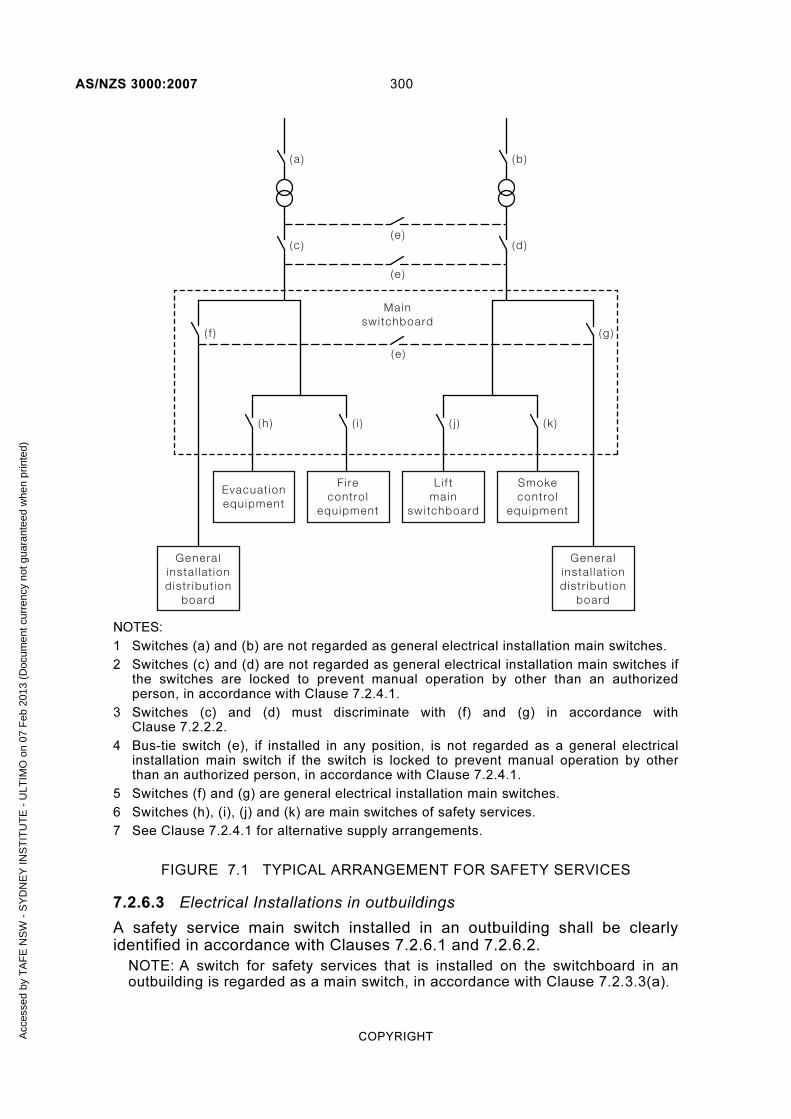
AS/NZS 3000:2007 300
COPYRIGHT
Li f tmain
swi tchboard
Smokecontro l
equipment
Evacuat ionequipment
Mainswi tchboard
Fi recontro l
equipment
Genera linsta l lat iondistr ibut ion
board
Genera linsta l lat iondistr ibut ion
board
(e )( c )
( h ) ( i ) ( j ) ( k )
( a )
( e )
( f )
(d )
(b )
(g )
( e )
NOTES:
1 Switches (a) and (b) are not regarded as general electrical installation main switches.
2 Switches (c) and (d) are not regarded as general electrical installation main switches if the switches are locked to prevent manual operation by other than an authorized person, in accordance with Clause 7.2.4.1.
3 Switches (c) and (d) must discriminate with (f) and (g) in accordance with Clause 7.2.2.2.
4 Bus-tie switch (e), if installed in any position, is not regarded as a general electrical installation main switch if the switch is locked to prevent manual operation by other than an authorized person, in accordance with Clause 7.2.4.1.
5 Switches (f) and (g) are general electrical installation main switches.
6 Switches (h), (i), (j) and (k) are main switches of safety services.
7 See Clause 7.2.4.1 for alternative supply arrangements.
FIGURE 7.1 TYPICAL ARRANGEMENT FOR SAFETY SERVICES
7.2.6.3 Electrical Installations in outbuildings
A safety service main switch installed in an outbuilding shall be clearly identified in accordance with Clauses 7.2.6.1 and 7.2.6.2.
NOTE: A switch for safety services that is installed on the switchboard in an outbuilding is regarded as a main switch, in accordance with Clause 7.2.3.3(a).
Acc
esse
d by
TA
FE
NS
W -
SY
DN
EY
INS
TIT
UT
E -
ULT
IMO
on
07 F
eb 2
013
(Doc
umen
t cur
renc
y no
t gua
rant
eed
whe
n pr
inte
d)

301 AS/NZS 3000:2007
COPYRIGHT
Any switch that—
(a) is located remote from an outbuilding in which safety services are provided; and
(b) operates in the supply circuit to a safety service main switch installed in the outbuilding;
shall be clearly identified in accordance with Clauses 7.2.6.1 and 7.2.6.2.
7.2.6.4 Special lifts
Main switches controlling lifts arranged in accordance with Clause 7.2.3.4 shall be identified in accordance with the requirements of Clauses 7.2.6.1 and 7.2.6.2 and distinguished from main switches controlling other lifts.
7.2.6.5 Identification of alternative supply system
Where an alternative supply system may be affected by the operation of a switch, the additional marking requirements of Clauses 2.3.4.4 and 7.3.8.1.2 may apply.
7.2.7 Wiring systems
7.2.7.1 General
Wiring systems associated with safety services shall be capable of maintaining an adequate supply to such equipment when exposed to fire.
7.2.7.2 Type of wiring
Wiring systems, including consumers mains, supplying safety services shall comply with AS/NZS 3013 with a WS classification as specified by the Standard relevant to the installation of such equipment.
NOTE: See Appendix H for further information regarding the application of the WS classification system.
Where the relevant Standard does not specify a WS classification, the wiring system shall be of a type that is capable of maintaining supply to the equipment—
(a) when exposed to either fire or mechanical damage; or
(b) when exposed to fire and that is protected against mechanical damage by—
(i) installation in a suitable enclosure; or
(ii) installation in a location where the system will not be exposed to mechanical damage.
Exception: The fire and mechanical protection requirements need not apply to the following:
(A) Wiring systems in an enclosure or location that provides protection against fire and mechanical damage, e.g. cables or enclosed wiring systems installed in underground locations, buried in concrete or masonry walls or floors, or installed in an appropriate fire-rated enclosure and provided with suitable mechanical protection.
Acc
esse
d by
TA
FE
NS
W -
SY
DN
EY
INS
TIT
UT
E -
ULT
IMO
on
07 F
eb 2
013
(Doc
umen
t cur
renc
y no
t gua
rant
eed
whe
n pr
inte
d)

AS/NZS 3000:2007 302
COPYRIGHT
(B) Circuits for fire detection and alarm systems complying with the AS 1670 series or NZS 4512 beyond the control and indicating panel.
(C) Circuits that provide the primary power source of fire detection and alarm systems that are provided with battery backup in accordance with the AS 1670 series or NZS 4512, up to the control and indicating panel.
(D) Circuits for fire detection for fire and smoke control equipment complying with AS/NZS 1668.1.
(E) Circuits for lighting and socket-outlets in pump rooms installed in accordance with Clause 7.2.4.3.
(F) Circuits of emergency warning systems that are provided with battery backup, in accordance with the AS 1670 series or NZS 4512, up to the main equipment panel.
(G) Circuits of emergency warning systems complying with the AS 1670 series or NZS 4512, beyond the main equipment panel.
(H) Circuits supplying lifts beyond the terminals of a circuit-breaker provided in the lift machine room for the control and protection of the lift installation.
(I) Circuits for electric-driven fire pumps that form part of a pump set that includes a stand-by fuel-driven pump.
(J) Circuits supplying battery chargers for battery-operated single-point lighting systems that are provided for emergency evacuation purposes.
7.2.8 Segregation
7.2.8.1 Switchgear
Where emergency equipment is required by National Building Codes, all switchboards that sustain supply to such equipment shall be constructed so that the emergency equipment switchgear is separated from other switchgear by metal partitions designed to minimize the spread of a fault from the other switchgear to the emergency switchgear.
7.2.8.2 Cables in the same enclosure
Conductors of safety services shall not be enclosed with different safety services or with conductors of any other system.
For the purposes of this Clause, the following applies:
(a) If a duct or trunking is divided into separate channels by means of fixed and continuous barriers that provide effective segregation, each channel may be regarded as a separate enclosure.
(b) Wiring systems complying with Clause 7.2.7.2 may be considered to provide effective segregation.
(c) Wiring systems within switchboards shall be segregated from all other wiring systems by a physical separation of at least 50 mm or by suitable barriers.
Acc
esse
d by
TA
FE
NS
W -
SY
DN
EY
INS
TIT
UT
E -
ULT
IMO
on
07 F
eb 2
013
(Doc
umen
t cur
renc
y no
t gua
rant
eed
whe
n pr
inte
d)

303 AS/NZS 3000:2007
COPYRIGHT
7.2.8.3 Conductors in multi-core cables
Conductors of different safety services shall not be incorporated with each other or with conductors of any other system within a multi-core cable.
7.2.9 Fire-pump motors
7.2.9.1 Isolating switches
Where fire-pump motors are automatically controlled, a manually operated isolating switch shall be connected on the supply side of the pump motor controller.
The isolating switch shall—
(a) comply with the requirements of Clause 2.3.2; and
(b) be installed adjacent to or on the pump motor controller; and
(c) be provided with a device for locking the switch in the closed position.
7.2.9.2 Overcurrent protection
The overload characteristics of overcurrent protective devices provided on circuits supplying fire-pump motors shall—
(a) have an inverse time characteristic; and
(b) be rated, or in the case of circuit-breakers be set, to—
(i) carry 125% of the full-load motor current continuously; and
(ii) open the circuit in not less than 20 s at 600% of the full-load motor current.
No other overload protective device shall be inserted between the pump motor controller and the motor.
Where more than one motor is provided on the same circuit, the overcurrent protective device may be rated or set to—
(A) carry 125% of the sum of the full-load current of all motors operating simultaneously; and
(B) open the circuit in not less than 20 s at 600% of the full-load current of the largest motor supplied.
7.2.9.3 Overtemperature protection
Overtemperature protective devices shall not be provided on fire-pump motors where the operation of such devices might reduce the operating time of the equipment under emergency conditions.
7.2.9.4 Control circuits
Control circuits associated with the operation of fire-pump motors shall—
(a) be directly connected between the active and neutral conductor of the pump circuit; and
NOTE: This requirement precludes the use of transformers.
Acc
esse
d by
TA
FE
NS
W -
SY
DN
EY
INS
TIT
UT
E -
ULT
IMO
on
07 F
eb 2
013
(Doc
umen
t cur
renc
y no
t gua
rant
eed
whe
n pr
inte
d)

AS/NZS 3000:2007 304
COPYRIGHT
(b) be arranged so that the active conductor of the control circuit is directly connected to the coil of the operating device within the starter; and
(c) not be provided with overload protective devices other than those provided for the pump-motor circuit, in accordance with Clause 7.2.9.2.
NOTE: This arrangement requires the installation of a switch in the neutral conductor of the control circuit for a fire pump.
7.3 ELECTRICITY GENERATION SYSTEMS
7.3.1 General
The requirements of this Clause supplement or amend the requirements of Sections 2 to 7 of this standard for electricity generation systems connected to electrical installations that are intended to supply, either continuously or occasionally, all or part of the installation.
An electricity generation system may consist of the following:
(a) Engine-driven generator set A generator set, typically combustion engine-driven, that—
(i) provides an alternative or stand-by a.c. electricity supply in the event of failure of the primary power supply to the installation; or
(ii) is used as the prime power supply to an electrical installation; or
(iii) is used as part of a stand-alone power system.
(b) Stand-alone power system A stand-alone power system that provides a connection to an electrical installation from a renewable energy source, such as photovoltaic, wind turbine or mini-hydro turbine, in the form of—
(i) an a.c. supply from an inverter output; or
NOTE: Such a system may also include an engine-driven generator set.
(ii) a d.c. power supply.
(c) Grid-connected inverter system A grid-connected inverter system that provides an a.c. power supply from an interactive inverter using a renewable energy source, such as photovoltaic, wind turbine or mini-hydro turbine.
NOTES:
1 ‘Grid-connected’ means that an installation is capable of being connected
in parallel with the distribution system.
2 A grid-connected inverter system may also include an engine-driven
generator set.
3 The connection of a grid-connected inverter system is subject to formal
agreement with the electricity distributor.
Acc
esse
d by
TA
FE
NS
W -
SY
DN
EY
INS
TIT
UT
E -
ULT
IMO
on
07 F
eb 2
013
(Doc
umen
t cur
renc
y no
t gua
rant
eed
whe
n pr
inte
d)

305 AS/NZS 3000:2007
COPYRIGHT
In the event of renewable energy output available exceeding the electrical installation load, subject to formal approval of the electricity distributor, any surplus energy available is exported into the distribution system.
If the output available from the renewable energy sources is insufficient for the installation loading, the shortfall in energy required is imported from the network.
The interactive inverter of the system also provides control of the exporting and importing of energy from the system and network.
(d) Battery system A battery system that provides supply from a renewable energy source, such as a generator set, photovoltaic, wind turbine or mini-hydro turbine, to charge a battery bank and provide a d.c. supply to an electrical installation.
7.3.2 Selection and installation of system
The selection, installation and control of electrical equipment that is intended to form an electricity system shall comply with the following Standards:
(a) Engine-driven generating sets....................... AS/NZS 3010.
(b) Stand-alone power systems .......................... AS 4509 (series).
(c) Battery systems ............................................ AS 3011.
(d) Photovoltaic array systems ........................... AS/NZS 5033.
(e) Grid connected inverter systems ................... AS 4777 (series).
7.3.3 Control
An electricity generation system shall be controlled by an isolating switch or switches at the source of supply or at the installation switchboard to which the connection of the electricity generation system is made.
The electricity generation system shall be controlled by switches or devices suitable for starting and stopping the electricity generation system. Where there is more than one switch or device for this purpose, they shall be grouped together and clearly identified.
An electricity generation system shall be so arranged that it cannot supply energy upstream of the point of connection to the installation either directly or indirectly.
Exception: An electricity distributor may enter into a formal agreement to permit co-generation (feed back or exporting into the upstream network) under specific conditions. Examples include grid-connected inverter-based systems or engine-driven generating systems intended to operate in parallel with the network.
NOTE: Conditions for the connection of grid-connected systems, co-generation and other systems that are intended to operate in parallel with the electricity distributors system are beyond the scope of this Standard.
A2
A2
Acc
esse
d by
TA
FE
NS
W -
SY
DN
EY
INS
TIT
UT
E -
ULT
IMO
on
07 F
eb 2
013
(Doc
umen
t cur
renc
y no
t gua
rant
eed
whe
n pr
inte
d)

AS/NZS 3000:2007 306
COPYRIGHT
Provision shall be made to ensure that all necessary connections for basic and fault protection in the installation, such as the MEN connection, remain intact when supply is available from the output of the electricity generation system.
7.3.4 Isolation
7.3.4.1 General
Each electricity generation system shall be provided with an isolating switch, in accordance with Clause 2.3.2.2, that—
(a) shall be—
(i) installed adjacent to, or on, the electricity generation system so that a person operating the switch has a clear view of any person working on the electricity generation system; or
(ii) provided with a means of securing the device in the isolated position that requires a deliberate action to engage or disengage; and
(b) may be combined with overcurrent protection required by Clause 7.3.5.1; and
(c) shall comply with Clause 4.13 when the electricity generation system incorporates an electric motor; and
(d) shall be under manual control only; and
(e) shall not be capable of being overridden or bypassed by programmable control systems or the like.
Exception: The isolation arrangements for systems, in accordance with AS/NZS 4509.1 or the AS 4777 series, are deemed to satisfy these requirements.
7.3.4.2 Electricity generation systems incorporating batteries
Where batteries are incorporated in an electricity generation system, a switch capable of interrupting the supply from such batteries shall be installed adjacent to the isolating switch (see Clause 7.3.4.1) and shall be clearly identified to indicate its purpose.
Exception: A single switch that incorporates both a.c. and d.c. switching functions outlined in Clause 7.3.4.1 and this Clause 7.3.4.2 may be used.
7.3.5 Overcurrent protection
7.3.5.1 Electricity generation system protection
Electricity generation systems shall be provided with overcurrent protection.
Exception: Overcurrent protective devices shall not be provided where the unexpected interruption of the supply could cause a greater danger than overcurrent.
Overcurrent protective devices shall be located as close as practicable to the output terminals of the electricity generation system so that the unprotected interconnecting conductors to an electrical installation are as short as practicable and, in no case, exceed 15 m in length.
A2
A2
Acc
esse
d by
TA
FE
NS
W -
SY
DN
EY
INS
TIT
UT
E -
ULT
IMO
on
07 F
eb 2
013
(Doc
umen
t cur
renc
y no
t gua
rant
eed
whe
n pr
inte
d)

307 AS/NZS 3000:2007
COPYRIGHT
The unprotected interconnecting conductors shall be completely enclosed by metal or other material that is not flammable.
Exception: Overcurrent protection may be provided by:
(a) an overcurrent protective device within the electricity generation system; or
(b) the characteristics of the electricity generation system being unable to support the fault current.
Where a single electricity generation system is intended to operate in parallel with another electricity generation system, circulating harmonic currents shall be limited so that the current carrying capacity of conductors is not exceeded.
NOTES: The effects of circulating harmonic currents may be limited as follows:
1 The selection of generating sets with compensated windings.
2 The provision of a suitable impedance in the connection to generator star points.
3 The provision of switches that interrupt the circulatory circuit but that are interlocked so that at all times fault protection is not impaired.
4 The provision of filtering equipment.
5 Other suitable means.
7.3.5.2 Circuit protection
7.3.5.2.1 General
The prospective short-circuit current and prospective earth fault current shall be assessed for each electricity generation system or combination of systems that can operate to supply an installation.
The short-circuit rating of protective devices within the electrical installation shall not be exceeded for any of the intended methods of operation of the electricity generation system.
NOTE: If the electricity generation system has an electronic overcurrent protection system fitted, e.g. inverters, such devices may automatically limit the output current and may prevent the operation of an external overcurrent device within the installation under fault conditions.
Every circuit outgoing from an electricity generation system shall be individually protected in accordance with Clause 2.5 and shall also include additional (earth leakage) protection where required by Clause 2.6.
A circuit is considered to be protected against prospective short-circuit and earth fault currents when it is supplied from an electricity generation system incapable of delivering a current exceeding the current-carrying capacity of the circuit.
NOTE: Typical supply sources include small generating sets or inverters fitted with electronic overload protection systems.
Exception: Overcurrent protective devices shall not be provided where the unexpected interruption of the supply could cause a greater danger than overcurrent.
Acc
esse
d by
TA
FE
NS
W -
SY
DN
EY
INS
TIT
UT
E -
ULT
IMO
on
07 F
eb 2
013
(Doc
umen
t cur
renc
y no
t gua
rant
eed
whe
n pr
inte
d)

AS/NZS 3000:2007 308
COPYRIGHT
7.3.5.2.2 RCDs
The possible waveform of a fault current to earth can affect the operation of RCDs and shall be taken into account for the selection of the type of RCD.
Where an electricity generation system includes an inverter, the RCD shall be of a type suitable for the waveform of the particular inverter, and in accordance with the inverter manufacturer’s recommendations.
NOTE: Requirements for types of RCDs are set out in Clause 2.6.2.2.
7.3.6 Earthing
The system of protective earthing in the electrical installation shall be in accordance with Section 5 of this Standard as an MEN system.
Exception: Where the output of the electricity generation system does not exceed 25 kVA, the output may be arranged as a separated supply, in accordance with the requirements of Clause 7.4.
Any exposed conductive parts of the electricity generation system shall be earthed by connection to the main earthing conductor at the main switchboard.
Where several independent electricity generation systems comprising engine-driven generating sets are required to operate in parallel as a single source, the connection to the neutral point of the windings of each generating set may be switched to ensure that only one neutral point is connected to earth at any one time.
NOTE: This provision for only one neutral connection for a group of generating sets connected in parallel is to prevent circulating currents between generating sets when operating.
7.3.7 Connected electrical equipment
Any accessory, conductor, insulation or other component connected to the output side of an electricity generation system shall be suitable for the voltage, current and frequency of the output of the unit.
NOTE: The values of current-carrying capacity and voltage drop specified in the AS/NZS 3008.1 series are valid only for conductors operating at 50 Hz.
7.3.8 Connection to electrical installation
7.3.8.1 Alternative supplies
The following shall apply to the connection of an alternative (stand-by) supply to an installation.
7.3.8.1.1 General
(a) The neutral-earth connection (MEN connection) shall be made within the installation at the switchboard to which the electricity generation system is connected (see Figures 7.2 to 7.4).
NOTE: This may require disconnection of any neutral–earth connection within an electricity generation system, such as an engine-driven generating set.
(b) The incoming neutral to a MEN switchboard shall not be switched.
Acc
esse
d by
TA
FE
NS
W -
SY
DN
EY
INS
TIT
UT
E -
ULT
IMO
on
07 F
eb 2
013
(Doc
umen
t cur
renc
y no
t gua
rant
eed
whe
n pr
inte
d)

309 AS/NZS 3000:2007
COPYRIGHT
NOTE: This applies to any switchboard fitted with an MEN connection and may be the main switchboard, or a switchboard in an outbuilding, regarded as a main switchboard for earthing purposes within the outbuilding.
(c) Neutral and earth conductors shall not operate in parallel.
Exception: When connected to a distribution switchboard and operating on the alternative supply, the submain neutral and protective earthing conductors may be operated in parallel through a remote MEN connection provided that—
(i) conductors are not overloaded by current sharing; and
(ii) conductors are suitable for the maximum calculated fault current; and
(iii) the nominal size of copper earthing conductors complies with the requirements of Clause 5.3.3; and
(iv) the current-carrying capacity of neutral conductors shall be not less than that of their associated active conductor.
7.3.8.1.2 Switching
The changeover device for an alternative supply shall be selected to maintain the function of, and prevent damage to, the electrical installation being supplied.
NOTE: Examples of functions to be maintained include the maintenance of the continuity of the neutral conductor (overlapping of neutrals), the operation of RCDs or the continued operation of uninterruptible power supplies.
The changeover device shall open all active conductors of the normal supply when the alternative supply is connected.
Where the operation of a switch automatically brings into service an alternative supply, the purpose of the switch shall be marked accordingly.
Switching arrangements in accordance with AS/NZS 3010 are deemed to satisfy these requirements.
NOTE: Typical switching arrangements are shown in Figures 7.2, 7.3 and 7.4.
A1
A2
Acc
esse
d by
TA
FE
NS
W -
SY
DN
EY
INS
TIT
UT
E -
ULT
IMO
on
07 F
eb 2
013
(Doc
umen
t cur
renc
y no
t gua
rant
eed
whe
n pr
inte
d)

AS/NZS 3000:2007 310
COPYRIGHT
L1 L2 L3 N E
L1 L2 L3 N
Ear th bar
Neutra l bar
Ear the lectrode
MENconnect ion
Normal supply(1,2 or 3 phases )
Local source suchas generat ing set or
inver ter(1,2 or 3 phase )
G
L3
L2
L1
N
To load
Changeover dev ice wi thinter locked swi tch ing
to AS/NZS 3010
Localsource
overcurrentprotect ion
(whereinsta l led )
Protect ive ear thto f rame of source
FIGURE 7.2 EXAMPLE OF CONNECTION OF AN ALTERNATIVE SUPPLY TO A SWITCHBOARD WITH A LOCAL MEN CONNECTION
(THREE POLE/FOUR POLE CHANGEOVER)
(Symbols are explained in Table J1.)
A1
Acc
esse
d by
TA
FE
NS
W -
SY
DN
EY
INS
TIT
UT
E -
ULT
IMO
on
07 F
eb 2
013
(Doc
umen
t cur
renc
y no
t gua
rant
eed
whe
n pr
inte
d)

311 AS/NZS 3000:2007
COPYRIGHT
L1 L2 L3NE
L1 L2 L3N
E -BAR
N-BAR
EE
MEN
To load
NORMAL SUPPLYLocal source such
as a generatingset or inverter
(1, 2 or 3 phase)
G
L3
L2
L1
N
Changeover Device
GeneratorOvercurrentProtection
(whereinstalled)
FIGURE 7.3 EXAMPLE OF CONNECTION OF AN ALTERNATIVE SUPPLY TO A SWITCHBOARD WITH A LOCAL MEN CONNECTION
(THREE POLE/THREE POLE CHANGEOVER)
(Symbols are explained in Table J1.)
A1
A2
Acc
esse
d by
TA
FE
NS
W -
SY
DN
EY
INS
TIT
UT
E -
ULT
IMO
on
07 F
eb 2
013
(Doc
umen
t cur
renc
y no
t gua
rant
eed
whe
n pr
inte
d)
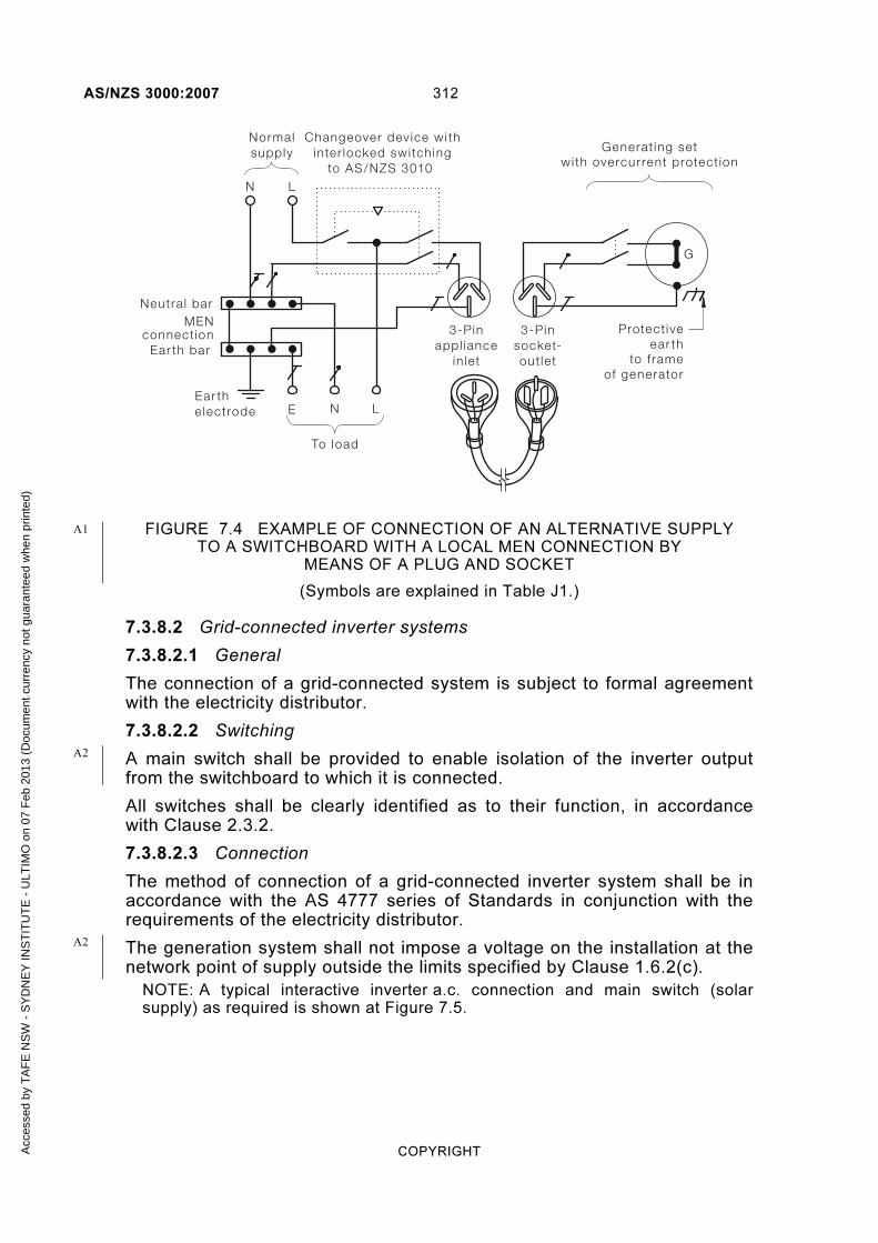
AS/NZS 3000:2007 312
COPYRIGHT
Ear th bar
Neutra l bar
L N E
L N
Ear the lectrode
MENconnect ion 3-Pin
appl iancein let
3-Pinsocket-out let
G
To load
Changeover dev ice wi thinter locked swi tch ing
to AS/NZS 3010
Normalsupply Generat ing set
wi th overcurrent protect ion
Protect iveear th
to f rameof generator
FIGURE 7.4 EXAMPLE OF CONNECTION OF AN ALTERNATIVE SUPPLY TO A SWITCHBOARD WITH A LOCAL MEN CONNECTION BY
MEANS OF A PLUG AND SOCKET
(Symbols are explained in Table J1.)
7.3.8.2 Grid-connected inverter systems
7.3.8.2.1 General
The connection of a grid-connected system is subject to formal agreement with the electricity distributor.
7.3.8.2.2 Switching
A main switch shall be provided to enable isolation of the inverter output from the switchboard to which it is connected.
All switches shall be clearly identified as to their function, in accordance with Clause 2.3.2.
7.3.8.2.3 Connection
The method of connection of a grid-connected inverter system shall be in accordance with the AS 4777 series of Standards in conjunction with the requirements of the electricity distributor.
The generation system shall not impose a voltage on the installation at the network point of supply outside the limits specified by Clause 1.6.2(c).
NOTE: A typical interactive inverter a.c. connection and main switch (solar supply) as required is shown at Figure 7.5.
A1
A2
A2
Acc
esse
d by
TA
FE
NS
W -
SY
DN
EY
INS
TIT
UT
E -
ULT
IMO
on
07 F
eb 2
013
(Doc
umen
t cur
renc
y no
t gua
rant
eed
whe
n pr
inte
d)
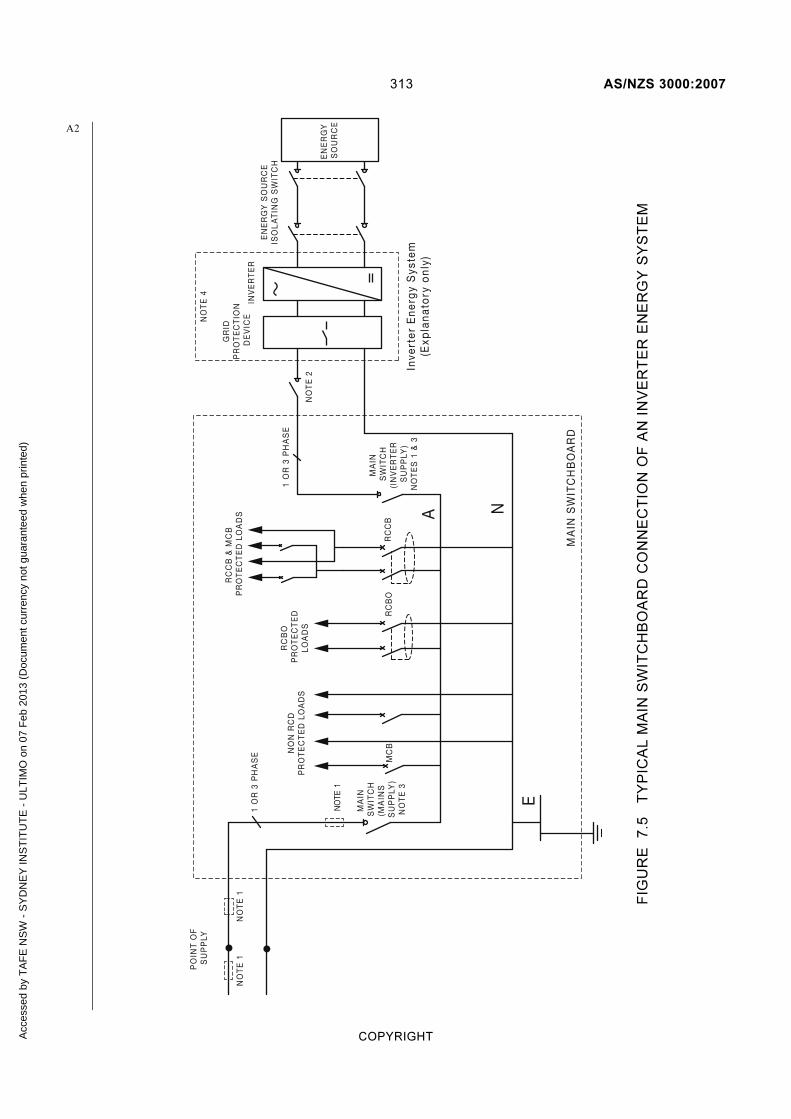
313 AS/NZS 3000:2007
COPYRIGHT
PO
INT
OF
S
UP
PLY
MA
IN
SW
ITC
H(M
AIN
S
SU
PP
LY)
NO
TE
3
NO
N R
CD
PR
OT
EC
TE
D L
OA
DS
RC
BO
P
RO
TE
CT
ED
LOA
DS
RC
CB
RC
CB
& M
CB
P
RO
TE
CT
ED
LO
AD
S
MA
IN
SW
ITC
H(I
NV
ER
TE
R
SU
PP
LY)
NO
TE
S 1
& 3
NO
TE 1
MA
IN S
WIT
CH
BO
AR
D
RC
BO
INV
ER
TE
R
GR
ID
PR
OT
EC
TIO
N
DE
VIC
E
A N
E
MC
B
NO
TE
1N
OT
E 1
EN
ER
GY
SO
UR
CE
ISO
LA
TIN
G S
WIT
CH
EN
ER
GY
S
OU
RC
E
NO
TE
2
NO
TE
4
Inve
rter
En
erg
y S
yste
m(E
xpla
nat
ory
on
ly)
1 O
R 3
PH
AS
E
1 O
R 3
PH
AS
E
A2
FIG
UR
E
7.5
T
YP
ICA
L M
AIN
SW
ITC
HB
OA
RD
CO
NN
EC
TIO
N O
F A
N I
NV
ER
TE
R E
NE
RG
Y S
YS
TE
M
Acc
esse
d by
TA
FE
NS
W -
SY
DN
EY
INS
TIT
UT
E -
ULT
IMO
on
07 F
eb 2
013
(Doc
umen
t cur
renc
y no
t gua
rant
eed
whe
n pr
inte
d)

AS/NZS 3000:2007 314
COPYRIGHT
NOTES TO FIGURE 7.5:
1 If overcurrent devices upstream of the main switch (inverter supply) do not protect the cabling to the inverter energy system, the main switch (inverter supply) should be a MCB with the rating to protect all cabling up to the inverter energy system a.c. input mains supply connection.
2 This isolating switch may be omitted if the inverter energy system is adjacent to the main switchboard and the main switch (inverter supply) isolator is visible from the inverter energy system location. The maximum cable route length should not exceed 3 m.
3 The isolating switches shall be lockable in the ‘OFF’ position.
4 All RCDs (RCCB or RCBO) in the a.c. input connection to the inverter energy system shall comply with the inverter manufacturer’s recommendations. If no inverter manufacturer’s recommendation is available, the default type of RCD is a Type B RCD. Refer to the AS 4777 series for further details.
5 The maximum voltage drop from the point of supply to the inverter energy system input connection via the main switchboard shall be controlled to provide stable inverter power system operation. Refer to the AS 4777 series for further details.
6 Revenue metering connections are not shown.
7 Earth connections are not shown.
8 For an energy source other than the one shown (i.e. a UPS or battery bank), refer to the AS 4777 series.
7.3.8.3 Stand-alone power systems
7.3.8.3.1 General
The consumers mains of the electrical installation shall be connected to the output of the electricity generating system.
7.3.8.3.2 Switching
Control of the electrical installation shall be arranged in accordance with Clause 2.3.
7.3.8.3.3 Connection
The method of connection of a stand-alone system shall be in accordance with the AS/NZS 4509 series of Standards.
NOTE: A typical stand-alone connection is shown in Figure 7.6 for an installation with a switchboard including a local MEN connection.
A1
A2
A2
Acc
esse
d by
TA
FE
NS
W -
SY
DN
EY
INS
TIT
UT
E -
ULT
IMO
on
07 F
eb 2
013
(Doc
umen
t cur
renc
y no
t gua
rant
eed
whe
n pr
inte
d)

315 AS/NZS 3000:2007
COPYRIGHT
L1 L2 L3 N E
Ear the lectrode
G
L3
L2
L1
N
To load
Localsource
overcurrentprotect ion
(whereinsta l led )
Local source suchas generat ing set or
inver ter as par t ofa stand-a lone
power system toAS 4509
Protect ive ear thto f rame of source
MENconnect ion
Ear th bar
Neutra l bar
Main swi tchboard
Mainswi tch
FIGURE 7.6 EXAMPLE OF CONNECTION OF A STAND-ALONE SYSTEM TO A SWITCHBOARD WITH A LOCAL MEN CONNECTION
(Symbols are explained in Table J1.)
7.4 ELECTRICAL SEPARATION (ISOLATED SUPPLY)
NOTE: The expression ‘electrical separation’ has the same meaning as ‘isolated supply’. ‘Electrical separation’ is used throughout this Clause.
7.4.1 Scope
Several methods of protection against electric shock arising from indirect contact are recognised by Clause 1.5.5 of this Standard. These methods include that of protection by electrical separation of the supply.
Protection by electrical separation is an alternative to other recognised methods and is intended, in an individual circuit, to prevent shock current through contact with exposed conductive parts that might be energized by a fault in the basic insulation of that circuit.
Protection by electrical separation shall be afforded by compliance with Clauses 7.4.2 to 7.4.4, and with—
(a) Clause 7.4.5 for a supply to one item of equipment; or
(b) Clause 7.4.6 for a supply to more than one item of equipment.
NOTE: Figure 7.7 provides an illustration of a separated supply to single and multiple items of equipment.
A1
Acc
esse
d by
TA
FE
NS
W -
SY
DN
EY
INS
TIT
UT
E -
ULT
IMO
on
07 F
eb 2
013
(Doc
umen
t cur
renc
y no
t gua
rant
eed
whe
n pr
inte
d)

AS/NZS 3000:2007 316
COPYRIGHT
7.4.2 Source of supply
The source supplying a separated circuit shall be—
(a) an isolating transformer complying with AS/NZS 61558 so that the output is separated from the input by double insulation or equivalent; or
(b) a generator output, e.g. a motor-generator set that is installed so that the output is separated from the frame of the generator; or
NOTE: The fitting of an RCD, and the connection of an equipotential bonding conductor and an additional conductor to the generator output winding to ensure the correct operation of the RCD, does NOT provide the output separation required by this Clause. See AS/NZS 3010 for details.
(c) an isolated inverter complying with the safety requirements of AS/NZS 4763 (Int).
7.4.3 Arrangement of circuits
Separated circuits shall comply with the following requirements:
(a) Circuit voltage shall not exceed 500 V.
(b) All live parts of a separated circuit shall be reliably and effectively electrically separated from all other circuits, including other separated circuits and earth.
NOTES:
1 This requirement can be satisfied by insulation of the live parts to Class II (double or reinforced insulation) or measures that are equivalent to the input and output transformer winding isolation provisions of AS/NZS 61558.
2 This requirement also applies to live parts of relays, contactors and similar electrical equipment installed in the separated circuit.
3 Each separated circuit should comprise a separate cable or wiring system. However, multi-core cables or a common non-conductive wiring enclosure may be used where the segregation requirements of Clause 3.9.8 are satisfied.
(c) Exposed conductive parts of electrical equipment supplied by a separated circuit shall not be connected to the protective earthing conductor, or the exposed conductive parts, of the source of supply.
(d) Cables and supply flexible cords to electrical equipment shall be protected against mechanical damage or otherwise arranged to ensure that any damage that might occur is readily visible.
7.4.4 Switching devices
Switching devices shall operate in all live conductors of a separated circuit.
NOTE: Switching of the active conductor(s) of the primary of an isolating transformer, in accordance with Clause 2.3.2, is an acceptable method of control and disconnection of supply.
Acc
esse
d by
TA
FE
NS
W -
SY
DN
EY
INS
TIT
UT
E -
ULT
IMO
on
07 F
eb 2
013
(Doc
umen
t cur
renc
y no
t gua
rant
eed
whe
n pr
inte
d)

317 AS/NZS 3000:2007
COPYRIGHT
7.4.5 Single item of electrical equipment
Where a separated circuit supplies a single item of electrical equipment, any exposed conductive parts of the electrical equipment shall not be connected to the exposed conductive parts of any other circuit, including other separated circuits or earth.
7.4.6 Multiple items of electrical equipment
Where a separated circuit supplies more than one item of electrical equipment, the following shall apply:
(a) Any exposed conductive parts of the separated circuit shall be connected together by an insulated equipotential bonding conductor that is not connected to—
(i) earth; or
(ii) a protective earthing conductor or exposed conductive parts of another circuit, including another separated circuit; or
(iii) any extraneous conductive parts.
(b) The designated earthing contact of any socket-outlet installed on the separated circuit shall be connected to the equipotential bonding conductor.
(c) The designated protective earthing conductor in any supply cable or flexible cord to electrical equipment (other than Class II [double or reinforced insulation] equipment) connected to the separated circuit shall be connected to the equipotential bonding conductor.
(d) Exposed conductive parts of the source of supply that are earthed, shall not be simultaneously accessible with any exposed conductive part of the separated circuit.
(e) A protective device shall operate to disconnect the separated circuit automatically in the event of two faults resulting in exposed conductive parts being connected to live parts of different polarity. If the protective device is a circuit-breaker, the protective device shall open in all unearthed conductors substantially together.
7.4.7 Testing
7.4.7.1 General
In addition to the testing requirements of Section 8 of this Standard, the separation of each separated circuit (transformer secondary winding or isolated winding generator output) and the wiring to the socket-outlet shall be individually confirmed.
Separation shall be verified by a measurement of the insulation resistance between the separated circuit and—
(a) if a transformer is the source of the separated supply, the transformer primary winding; and
(b) any other wiring; and
(c) any other separated circuit; and
Acc
esse
d by
TA
FE
NS
W -
SY
DN
EY
INS
TIT
UT
E -
ULT
IMO
on
07 F
eb 2
013
(Doc
umen
t cur
renc
y no
t gua
rant
eed
whe
n pr
inte
d)

AS/NZS 3000:2007 318
COPYRIGHT
(d) earth.
Insulation resistance values obtained shall be not less than 1 MΩ, when tested at a voltage of 500 V d.c.
NOTE: Where final subcircuits are not of significant length, the insulation resistance of the separated circuit should be significantly greater than 1 MΩ, e.g. with short lengths (say 50 m) of polymeric cable a value in excess of 50 MΩ would be expected.
7.4.7.2 Single items of electrical equipment
Where a single item of electrical equipment is supplied from a single separated circuit, separation shall be verified in accordance with Clause 7.4.7.1 and, in addition, by a measurement of the insulation resistance between earth and—
(a) exposed conductive parts; or
(b) the earth contact of a socket-outlet.
7.4.7.3 Multiple items of electrical equipment
Where more than one item of electrical equipment is supplied from a single separated circuit, separation shall be verified in accordance with Clause 7.4.7.1 and, in addition, by a measurement of the insulation resistance between—
(a) the separated circuit and the equipotential bonding conductor; and
(b) the equipotential bonding conductor and earth; and
(c) the equipotential bonding conductor and any equipotential bonding conductor associated with another separated circuit.
7.4.7.4 Bonding conductor continuity
The resistance of an equipotential bonding conductor for the earth contacts of socket-outlets, or exposed conductive parts connected to the same separated circuit, shall not exceed 0.5Ω.
Acc
esse
d by
TA
FE
NS
W -
SY
DN
EY
INS
TIT
UT
E -
ULT
IMO
on
07 F
eb 2
013
(Doc
umen
t cur
renc
y no
t gua
rant
eed
whe
n pr
inte
d)
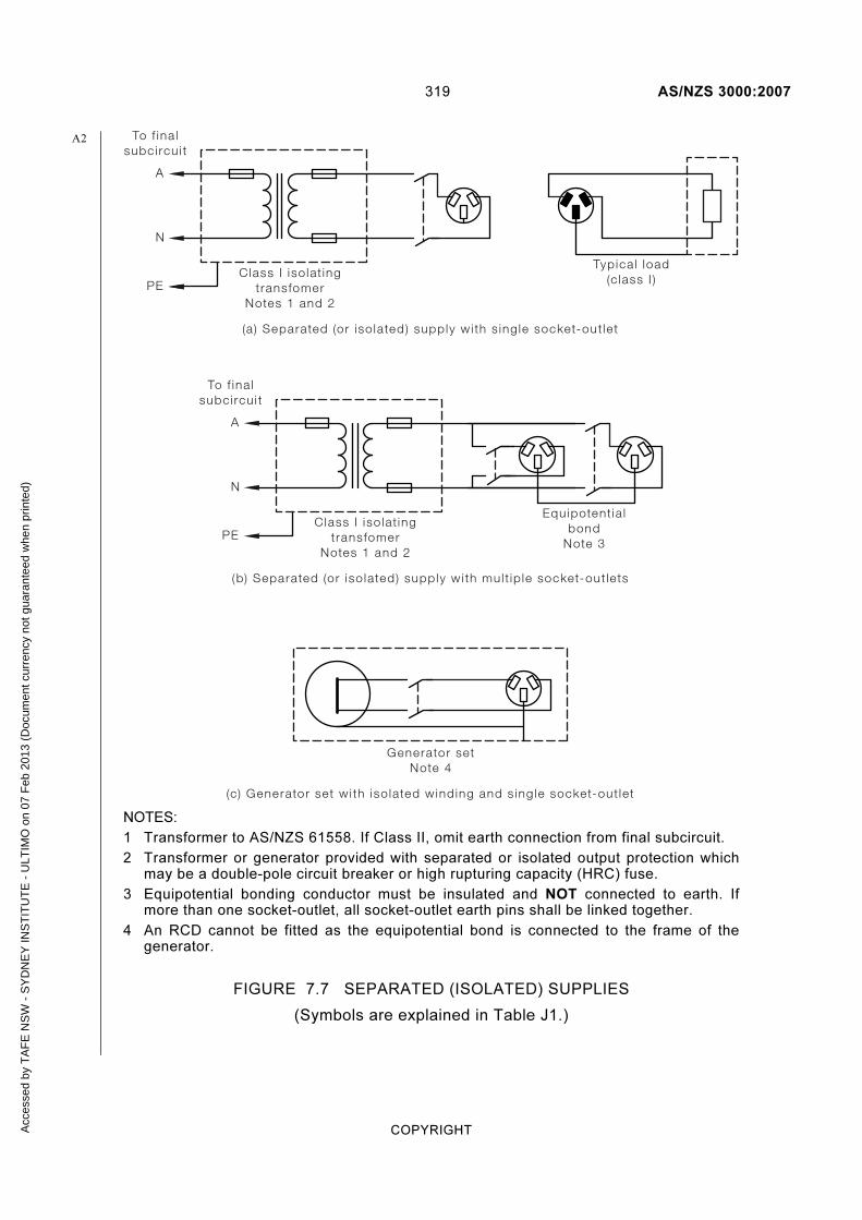
319 AS/NZS 3000:2007
COPYRIGHT
(a ) Separated (or iso lated) supply wi th s ing le socket-out let
A
N
Class I iso lat ingtransfomer
Notes 1 and 2
To f ina lsubci rcu i t
Typica l load(c lass I )
(b) Separated (or iso lated) supply wi th mul t ip le socket-out lets
To f ina lsubci rcu i t
A
N
PE
PE
Class I iso lat ingtransfomer
Notes 1 and 2
Equipotent ia lbond
Note 3
(c) Generator set wi th iso lated winding and s ing le socket-out let
Generator setNote 4
NOTES:
1 Transformer to AS/NZS 61558. If Class II, omit earth connection from final subcircuit.
2 Transformer or generator provided with separated or isolated output protection which may be a double-pole circuit breaker or high rupturing capacity (HRC) fuse.
3 Equipotential bonding conductor must be insulated and NOT connected to earth. If more than one socket-outlet, all socket-outlet earth pins shall be linked together.
4 An RCD cannot be fitted as the equipotential bond is connected to the frame of the generator.
FIGURE 7.7 SEPARATED (ISOLATED) SUPPLIES
(Symbols are explained in Table J1.)
A2
Acc
esse
d by
TA
FE
NS
W -
SY
DN
EY
INS
TIT
UT
E -
ULT
IMO
on
07 F
eb 2
013
(Doc
umen
t cur
renc
y no
t gua
rant
eed
whe
n pr
inte
d)

AS/NZS 3000:2007 320
COPYRIGHT
7.5 EXTRA-LOW VOLTAGE ELECTRICAL INSTALLATIONS
7.5.1 Scope
This Clause 7.5 applies to electrical installations or parts of electrical installations operating at extra-low voltage and sets out requirements for compliance with the provisions of Clause 1.5.7 of this Standard for both basic and fault protection (protection against both direct contact and indirect contact) by the use of extra-low voltage.
7.5.2 Compliance with other Sections
Extra-low voltage electrical installations shall be one of the following systems—
(a) SELV; or
(b) PELV.
The particular requirements of this Clause 7.5 supplement, replace or modify requirements of other Sections of this Standard.
Where no particular requirement is specified in this Clause extra-low voltage electrical installations shall comply with the relevant requirements of other Sections of this Standard.
Where an electrical installation operates at extra-low voltage but does not comply with the SELV or PELV requirements of this Clause 7.5 it shall be deemed to be operating at low voltage and shall be subject to the relevant requirements of other Sections of this Standard.
7.5.3 Sources of supply by SELV and PELV
The source supplying an SELV or a PELV system shall be one of the following:
(a) A safety isolating transformer complying with AS/NZS 61558.
(b) A source of current independent of a higher voltage supply, such as an engine-driven generator, or an electrochemical source, such as a battery.
(c) A source of current separated from higher voltage electrical installations, such as a motor-generator set, with electrically separate windings having a degree of electrical separation equivalent to that required by Item (a).
(d) Certain electronic devices complying with appropriate Standards, where, in the case of an internal fault, the voltage at the output terminals cannot exceed extra-low voltage. Higher voltages at the output terminals may be used, provided that the voltage at the output terminals is immediately reduced to extra-low voltage if contact is made with live parts under normal or fault conditions.
NOTE: Such devices include insulation testing equipment.
Acc
esse
d by
TA
FE
NS
W -
SY
DN
EY
INS
TIT
UT
E -
ULT
IMO
on
07 F
eb 2
013
(Doc
umen
t cur
renc
y no
t gua
rant
eed
whe
n pr
inte
d)

321 AS/NZS 3000:2007
COPYRIGHT
7.5.4 Separation requirements for SELV and PELV circuits
Live parts of SELV and PELV circuits shall be electrically separated from each other and from other higher voltage circuits.
Arrangements shall ensure a level of electrical separation equivalent to that between the input and output of a safety isolating transformer complying with AS/NZS 61558.
SELV and PELV circuit conductors shall be segregated from those of other circuit conductors.
Exception: SELV and PELV circuit conductors installed in accordance with Clause 3.9.8.3 may be contained within the same wiring system as low voltage circuits.
Live parts shall be arranged so that short-circuit or arcing, either between live parts or between live parts and other conductive material, will not take place under the conditions that may reasonably be expected in service.
7.5.5 Arrangement of SELV circuits
Live parts of SELV circuits shall not be connected to earth or protective earthing conductors that are part of other circuits or to other live parts.
SELV circuits shall not be connected to—
(a) other circuits; or
(b) earth; or
(c) earthing conductors or exposed conductive parts of another system; or
(d) extraneous conductive parts.
Exception: Connection to extraneous conductive parts may be made where electrical equipment is inherently required to be so connected and it is ensured that the extraneous conductive parts cannot attain a voltage exceeding that of the SELV circuit.
NOTE: If SELV circuits are liable to come into contact, either fortuitously or intentionally, with the exposed conductive parts of other circuits, protection against electric shock no longer depends solely on protection by SELV but on the protective measure to which the latter exposed conductive parts are subject.
Where the nominal voltage exceeds 25 V a.c. or 60 V ripple-free d.c., protection against electric shock in normal service (direct contact) shall be provided by—
(i) barriers or enclosures with a degree of protection of at least IPXXB or IP2X; or
(ii) insulation capable of withstanding a test voltage of 500 V a.c. for 1 min.
NOTES:
1 Basic protection is not necessary for voltages not exceeding 25 V a.c. or 60 V ripple-free d.c., in dry indoor conditions.
2 Insulation is capable of withstanding the test voltage for the required period when the insulation resistance after the test voltage has been applied for the specified period remains above the required minimum value.
Acc
esse
d by
TA
FE
NS
W -
SY
DN
EY
INS
TIT
UT
E -
ULT
IMO
on
07 F
eb 2
013
(Doc
umen
t cur
renc
y no
t gua
rant
eed
whe
n pr
inte
d)
AS/NZS 3000:2007 322
COPYRIGHT
7.5.6 Arrangement of PELV circuits
The following applies for PELV circuits, where one conductor of the output circuit is earthed.
Basic protection shall be provided by—
(a) barriers or enclosures affording the degree of protection at least IPXXB or IP2X; or
(b) insulation capable of withstanding a test voltage of 500 V a.c. for 1 min.
Exception: Basic protection shall be deemed unnecessary if electrical equipment is within the zone of influence of equipotential bonding and the nominal voltage does not exceed—
(i) 25 V a.c. or 60 V ripple-free d.c., when electrical equipment is normally used in a dry location only and large-area contact with the human body is not to be expected; or
(ii) 6 V a.c. or 15 V ripple-free d.c., in all other cases.
NOTES:
1 The earthing of circuits may be achieved by an appropriate connection to earth within the source itself.
2 AS/NZS 60479 indicates that large-area contact is approximately 8000 mm2.
3 Insulation is capable of withstanding the test voltage for the required period when the insulation resistance, after the test voltage has been applied for the specified period, remains above the required minimum value.
7.5.7 Voltage drop in conductors
The drop in voltage at any point in an extra-low voltage electrical installation shall not exceed 10% of the nominal value when all live conductors are carrying the circuit-operating current.
NOTE: Information on voltage drop is given in the AS/NZS 3008.1 series.
Exception: This requirement need not apply where electrical equipment is specially designed for operation with a voltage drop greater than 10%.
NOTE: Motor starting, solenoid closing and other similar applications where high transient currents may be experienced that can significantly increase voltage drop are excluded from consideration.
7.5.8 Control of an electrical installation
7.5.8.1 Main switches
The supply to an extra-low voltage electrical installation shall be controlled by a main switch or switches operating in all unearthed conductors.
Exception: This requirement need not apply where the extra-low voltage electrical installation is supplied from part of an electrical installation operating at a voltage greater than extra-low voltage and the operation of the main switch for the high voltage part of the electrical installation results in the disconnection of the supply.
Acc
esse
d by
TA
FE
NS
W -
SY
DN
EY
INS
TIT
UT
E -
ULT
IMO
on
07 F
eb 2
013
(Doc
umen
t cur
renc
y no
t gua
rant
eed
whe
n pr
inte
d)
323 AS/NZS 3000:2007
COPYRIGHT
7.5.8.2 Other switches
Switches in an extra-low voltage electrical installation shall comply with the following:
(a) A switch shall operate in all unearthed conductors where the extra-low voltage supply is earthed at the point of supply, e.g. PELV.
(b) Switches may operate in one less conductor than the number of conductors in the circuit, e.g. SELV.
7.5.9 Overcurrent protection
7.5.9.1 General
Every extra-low voltage circuit shall be individually protected at its origin against overload and short-circuit currents by a protective device that—
(a) shall comply with the appropriate requirements of Clauses 2.2 and 2.5; and
(b) may be provided in one conductor less than the number of conductors in the circuit.
Where the extra-low voltage supply is earthed at the point of supply, the protective devices shall be installed in all the unearthed conductors.
Exception: Circuits arranged in accordance with Clause 7.5.9.2 need not be provided with overcurrent protection.
7.5.9.2 Omission of overcurrent protection
Overcurrent protection need not be provided where—
(a) the expected interruption to supply could result in a greater danger than the overcurrent; or
(b) the rated output of the source of supply does not exceed the current rating of the circuit; and
(c) the circuit is supplied from either of the following sources:
(i) A transformer marked to indicate it is short-circuit proof in accordance with AS/NZS 61558 and—
(A) the rated output of the transformer does not exceed 1 A; or
(B) the short-circuit current of the transformer does not exceed the current-carrying capacity of the circuit conductors and such short-circuit current is marked on the transformer.
(ii) A battery, comprising cells having a high internal resistance, e.g. Leclanché or dry-type primary cells.
7.5.10 Connecting devices
Plug and socket-outlet devices, including installation couplers, for SELV and PELV shall comply with the following:
(a) Plugs shall not be able to enter sockets of other voltage systems.
(b) Sockets shall not accept plugs of other voltage systems.
(c) Sockets shall not have a contact for a protective earthing conductor.
Acc
esse
d by
TA
FE
NS
W -
SY
DN
EY
INS
TIT
UT
E -
ULT
IMO
on
07 F
eb 2
013
(Doc
umen
t cur
renc
y no
t gua
rant
eed
whe
n pr
inte
d)

AS/NZS 3000:2007 324
COPYRIGHT
7.5.11 Wiring systems
7.5.11.1 General
Conductors and insulation of cables for extra-low voltage electrical installations shall be suitable for the intended purpose and need not be further protected unless installation conditions so demand.
NOTE: Attention is drawn to the requirements of Clause 3.9.8.3 for segregation of different wiring systems and the need for further protection in some situations.
7.5.11.2 Aerial conductors
Aerial conductors used in extra-low voltage electrical installations shall be installed in accordance with the appropriate requirements of Clause 3.12.
Exceptions:
1 The clearances above ground or elevated areas need not apply provided that the requirements of Clause 3.3.1 are satisfied.
2 Bare conductors may be erected in accordance with the requirements for insulated conductors.
7.5.11.3 Underground conductors
There are no depth-of-burial requirements for the safety of extra-low voltage cables.
NOTE: Consideration should be given to the risk of mechanical damage.
7.5.12 Testing
7.5.12.1 General
The separation of ELV circuits shall be verified in accordance with Clause 7.5.12.2 in the case of protection by SELV, and Clause 7.5.12.3 in the case of protection by PELV.
The insulation resistance value obtained in Clauses 7.5.12.2 and 7.5.12.3 shall not be less than 0.5 MΩ when tested at a voltage of 250 V d.c.
7.5.12.2 Protection by SELV
The separation of live parts from those of other circuits and from earth shall be confirmed by a measurement of the insulation resistance.
7.5.12.3 Protection by PELV
The separation of live parts from other circuits shall be confirmed by a measurement of the insulation resistance.
7.6 HIGH VOLTAGE ELECTRICAL INSTALLATIONS
7.6.1 Scope
The provisions of this Clause 7.6 apply to electrical installations and those portions of electrical installations operating at high voltage.
For protection and earthing purposes, this Clause also applies to all the electrical equipment up to and including any low voltage cables and switchgear associated with high voltage transformers.
Acc
esse
d by
TA
FE
NS
W -
SY
DN
EY
INS
TIT
UT
E -
ULT
IMO
on
07 F
eb 2
013
(Doc
umen
t cur
renc
y no
t gua
rant
eed
whe
n pr
inte
d)

325 AS/NZS 3000:2007
COPYRIGHT
This Clause 7.6 does not apply to the following:
(a) Electric discharge illumination systems.
(b) X-ray equipment.
(c) High frequency equipment.
(d) High voltage wiring and electrical equipment enclosed within self-contained electrical equipment and supplied at low voltage where appropriate precautions have been taken to prevent contact with high voltage conductors.
7.6.2 Application
7.6.2.1 In Australia
In Australia electrical installations and those portions of electrical installations operating at high voltage shall be installed in accordance with AS 2067.
7.6.2.2 In New Zealand
In New Zealand electrical installations and those portions of electrical installations operating at high voltage shall be installed in accordance with the requirements of the New Zealand Electrical Regulations.
7.6.3 Issues relevant to high voltage installations
When designing high voltage electrical installations, consideration must be given to a range of issues that are more significant than those for electrical installations less than 1 kV.
Such issues include the following:
(a) Insulation levels to withstand highest voltage and/or impulse withstand voltages.
(b) Minimum clearances to live parts taking into account electrode configurations and impulse withstand voltages.
(c) Minimum clearances under special conditions.
(d) The application of various devices connected to the system.
(e) The methods of installation of equipment, cables and accessories.
(f) General requirements of installations regarding choice of circuit arrangement, documentation, transport routes, lighting, operational safety and labelling.
(g) Special requirements with respect to buildings.
(h) Protection measures with respect to access.
(i) Protection measures with respect to fire.
(j) Provision of earthing such that the system operates under all conditions and ensures safety of human life where there is legitimate access.
(k) Testing.
A
NZ
A1
A1
Acc
esse
d by
TA
FE
NS
W -
SY
DN
EY
INS
TIT
UT
E -
ULT
IMO
on
07 F
eb 2
013
(Doc
umen
t cur
renc
y no
t gua
rant
eed
whe
n pr
inte
d)

AS/NZS 3000:2007 326
COPYRIGHT
7.7 HAZARDOUS AREAS (EXPLOSIVE GAS OR COMBUSTIBLE DUSTS)
7.7.1 Scope
The particular requirements of this Clause 7.7 apply to the selection of electrical equipment and its installation to ensure safe use in areas where flammable or combustible materials are produced, prepared, processed, handled, stored or otherwise exist, and therefore may give rise to an explosive atmosphere.
7.7.2 Classification of hazardous areas
7.7.2.1 Responsibility for classification
The responsibility for classification of a hazardous area rests with the persons or parties in control of the installation. The requirements are contained in AS/NZS 60079.10.1 for gas or vapour and AS/NZS 60079.10.2 for combustible dust.
7.7.2.2 Recognized hazardous areas
Two general hazardous areas are recognized as follows:
(a) Hazardous area (gas or vapour) in which an explosive gas atmosphere is present, or may be expected to be present, in quantities such as to require special precautions for the construction, installation and use of apparatus
NOTES:
1 Hazardous areas are divided into zones based upon the frequency and duration of the occurrence of explosive gas atmospheres.
2 Explosive gas atmospheres include flammable vapours (from liquids).
(b) Hazardous area (dust) in which combustible dust in the form of a cloud is present, or may be expected to be present, in quantities such as to require special precautions for the construction, installation and use of equipment.
NOTES:
1 Hazardous areas are divided into zones based upon the frequency and duration of the occurrence of explosive dust atmospheres.
2 The potential of creating an explosive dust cloud from a dust layer should be considered.
3 Combustible dusts may include fibres and flyings.
7.7.2.3 Reduction or elimination of the hazard
Through design and operation, it is possible to reduce the degree of hazard. This is achieved by giving attention to items such as plant layout, product containment and ventilation.
7.7.2.4 Electrical equipment
7.7.2.4.1 Selection
Electrical equipment selected for use in hazardous areas shall comply with the appropriate requirements as specified in AS/NZS 60079.14.
A2
A2
A2
Acc
esse
d by
TA
FE
NS
W -
SY
DN
EY
INS
TIT
UT
E -
ULT
IMO
on
07 F
eb 2
013
(Doc
umen
t cur
renc
y no
t gua
rant
eed
whe
n pr
inte
d)

327 AS/NZS 3000:2007
COPYRIGHT
7.7.2.4.2 Installation
Electrical equipment shall be installed in accordance with the installation requirements of AS/NZS 60079.14.
NOTES:
1 AS/NZS 60079.14 includes requirements for the competency of persons.
2 AS/NZS 60079.17 includes requirements for inspection and maintenance.
7.8 SPECIFIC ELECTRICAL INSTALLATION STANDARDS
7.8.1 Scope
This Clause outlines those Standards that are applicable to specific electrical installations.
These Standards contain—
(a) additional requirements of this Standard; and
(b) requirements that, when fully satisfied, are deemed to comply with this Standard; and
(c) guidance for specific electrical installations and situations that, although not required by this Standard, may be required by relevant regulatory authorities. The method of applying these and other Standards varies in the different jurisdictions.
7.8.2 Additional requirements of this Standard
7.8.2.1 Construction and demolition sites
Electrical installations for construction and demolition sites shall comply with AS/NZS 3012.
7.8.2.2 Electromedical treatment areas
Electrical installations in electromedical treatment areas shall comply with AS/NZS 3003.
7.8.2.3 Transportable structures and vehicles including their site supplies
Electrical installations in transportable structures and vehicles including their site supplies shall comply with AS/NZS 3001.
7.8.2.4 Marinas and recreational boats
Electrical installations in marinas and recreational boats shall comply with AS/NZS 3004.
NOTES:
1 AS/NZS 3004 is a two-part Standard as follows:
(a) AS/NZS 3004.1 provides requirements for electrical installations on marinas; and
(b) AS/NZS 3004.2 provides requirements for electrical installations in recreational boats.
A1
A1
A2
Acc
esse
d by
TA
FE
NS
W -
SY
DN
EY
INS
TIT
UT
E -
ULT
IMO
on
07 F
eb 2
013
(Doc
umen
t cur
renc
y no
t gua
rant
eed
whe
n pr
inte
d)

AS/NZS 3000:2007 328
COPYRIGHT
2 In Australia, for electrical installations on commercial vessels, refer to the National Marine Safety Committee’s National standard for commercial vessels Part C: Design and construction—Section 5: Engineering—Subsection 5B: Electrical (NSCV C 5B).
7.8.2.5 Shows and carnivals
Electrical installations in shows and carnivals shall comply with AS/NZS 3002.
7.8.2.6 Cold-cathode illumination systems
The installation of cold-cathode illumination systems (electric discharge illumination systems) shall comply with AS/NZS 3832.
7.8.2.7 Telecommunications networks power supplies
Extra-low voltage (d.c.) power supply installations within public telecommunications networks shall comply with AS/NZS 3015.
7.8.2.8 Cranes and hoists
The electrical installation of every crane and hoist installation shall comply with the appropriate requirements of this Standard.
NOTE: Such electrical installations may be subject to the requirements of the AS 1418 series or other requirements of the relevant regulatory authorities.
7.8.2.9 Lifts
The electrical installation of lifts shall be installed in accordance with the appropriate requirements of this Standard.
NOTES:
1 See Clause 7.2.3.4 for requirements affecting the control and arrangement of special lift installations.
2 Such electrical installations are within the scope of the AS 1735 series and compliance therewith may be required by the relevant regulatory authorities.
7.8.3 Deemed to comply Standards
7.8.3.1 Domestic electrical installations
Electrical installations in single domestic electrical installations that comply with AS/NZS 3018 are deemed to comply with this Standard.
7.8.4 Specific electrical installation guidance
7.8.4.1 Generating Sets
Guidance on the minimum safety requirements for the installation and use of generating sets for the supply of electricity at voltages normally exceeding 50 V a.c. or 120 V d.c. is given in AS/NZS 3010.
7.8.4.2 Outdoor sites under heavy conditions
Electrical installations in outdoor sites under heavy conditions shall comply with the appropriate requirements of this Standard in so far as they are relevant and applicable.
AA1
Acc
esse
d by
TA
FE
NS
W -
SY
DN
EY
INS
TIT
UT
E -
ULT
IMO
on
07 F
eb 2
013
(Doc
umen
t cur
renc
y no
t gua
rant
eed
whe
n pr
inte
d)

329 AS/NZS 3000:2007
COPYRIGHT
Such sites include, but are not limited to, open-cast mines, quarries, stockpiles and other industrial areas exposed to particularly onerous environmental and operational conditions.
NOTE: Such electrical installations are within the scope of the AS 3007 series. Compliance with the AS 3007 series or other requirements, although not a requirement of this Standard, may be required by relevant regulatory authorities.
7.8.4.3 Electric fences
Guidance on the installation requirements for electric fences is given in AS/NZS 3014 and AS/NZS 3016.
Where an electrically operated fence is connected directly or indirectly to electricity supply mains, such connections shall be made only through a mains-operated fence controller complying with AS/NZS 60335.2.76.
7.8.4.4 Film, video and television sites
Guidance on the safe working procedures for the use of electrical equipment and temporary electrical installations on film, video and television sites is given in AS/NZS 4249.
NOTE: Compliance with AS/NZS 4249 or other requirements, although not a requirement of this Standard, may be required by relevant regulatory authorities.
Acc
esse
d by
TA
FE
NS
W -
SY
DN
EY
INS
TIT
UT
E -
ULT
IMO
on
07 F
eb 2
013
(Doc
umen
t cur
renc
y no
t gua
rant
eed
whe
n pr
inte
d)

AS/NZS 3000:2007 330
COPYRIGHT
S E C T I O N 8 V E R I F I C A T I O N
8.1 GENERAL
8.1.1 Application
The provisions of Section 8 represent the minimum standard of inspection and testing that must be achieved to satisfy the fundamental safety principles of Part 1 of this Standard in relation to verification of an installation.
8.1.2 Requirements
Prior to placing an electrical installation, or any part thereof, in service following construction, alteration, addition or repair thereof, it shall be verified, as far as practicable, that the installation is safe to energize and will operate correctly in accordance with the requirements of this Standard.
To confirm that the requirements of this Standard have been met, after completion and before being placed in service, the installation shall be—
(a) inspected as far as is practicable; and
(b) tested in accordance with Clause 8.3.
Precautions shall be taken to ensure the safety of persons and to avoid damage to property and the electrical installation equipment during inspection and testing.
Where the electrical installation is an alteration, addition or repair to an existing electrical installation, it shall be verified that the alteration, addition or repair complies with this Standard and does not impair the safety of the existing electrical installation.
Exception: Certain types of test, such as those involving thermal properties and operation, may be carried out after the electrical installation has been placed in service.
Periodic inspection and testing of electrical installations shall be performed in accordance with the requirements of:
(i) the regulatory authority; or
(ii) the owner or occupier of the premises.
Recommended periodic testing arrangements are set out in AS/NZS 3019.
NOTE: Additional visual inspections and testing may be required for specific installations, such as separated supplies, SELV and PELV installations, electromedical installations, transportable structures and vehicles and marinas, etc.
Guidance for these electrical installations can be obtained from the provisions of Section 7 and the specific installation Standards referenced in Clause 7.8.
A1
Acc
esse
d by
TA
FE
NS
W -
SY
DN
EY
INS
TIT
UT
E -
ULT
IMO
on
07 F
eb 2
013
(Doc
umen
t cur
renc
y no
t gua
rant
eed
whe
n pr
inte
d)
331 AS/NZS 3000:2007
COPYRIGHT
8.2 VISUAL INSPECTION
8.2.1 General
A visual inspection shall be made when work on an electrical installation has been completed in order to verify that the work complies with the requirements of this Standard.
The visual inspection shall be carried out before, or in association with, testing and should, where practicable, be made before the relevant part of the electrical installation is placed in service.
Where the visual inspection of a part of the electrical installation is not practicable at the completion of the work, e.g. not accessible because of enclosure in the building structure, consideration should be given to inspecting that part during the course of the installation.
8.2.2 Checklist
The following items provide a guide to the matters to be checked during the visual inspection to assess that the relevant requirements of this Standard are satisfied:
(a) General:
(i) Basic protection (protection against direct contact with live parts), e.g. insulation and enclosure.
(ii) Fault protection (protection against indirect contact with exposed conductive parts), e.g. by the use of automatic disconnection of supply, double insulation or isolating transformers.
(iii) Protection against hazardous parts, e.g. enclosure, guarding or screening of flammable materials, hot surfaces and parts that may cause physical injury.
(iv) Protection against spread of fire, e.g. penetration of fire barriers.
(v) General condition of the electrical equipment, e.g. signs of damage that could impair safe operation, disconnection of unused electrical equipment.
(b) Consumers mains:
(i) Current carrying capacity.
(ii) Voltage drop, e.g. size of conductors.
(iii) Underground installation conditions, e.g. enclosure, depth of burial, mechanical protection.
(iv) Aerial installation conditions.
(v) Connection of wiring.
(vi) Protection against external influences.
(c) Switchboards:
(i) Location, e.g. access and egress.
Acc
esse
d by
TA
FE
NS
W -
SY
DN
EY
INS
TIT
UT
E -
ULT
IMO
on
07 F
eb 2
013
(Doc
umen
t cur
renc
y no
t gua
rant
eed
whe
n pr
inte
d)

AS/NZS 3000:2007 332
COPYRIGHT
(ii) Protective devices, e.g. selection and setting of adjustable protective devices for compliance with overcurrent protection, arc fault protection and discrimination requirements.
(iii) Isolating devices, e.g. main switches.
(iv) Connecting devices, e.g. neutral bars, earth bars and active links.
(v) Connection and fixing of wiring and switchgear.
(vi) Identification and labelling of electrical equipment.
(vii) Protection against external influences.
(d) Wiring systems:
(i) Conductor size, e.g. current-carrying capacity and voltage drop.
(ii) Identification of cable cores.
(iii) Adequate support and fixing.
(iv) Connections and enclosures.
(v) Particular installation conditions, e.g. underground, aerial, safety services.
(vi) Segregation from other services and electrical installations.
(vii) Protection against external influences, e.g. enclosure.
(e) Electrical equipment:
(i) Isolation and switching devices for protection against injury from mechanical movement devices and motors.
(ii) Isolation and switching devices for protection against thermal effects, e.g. motors, room heaters, water heaters.
(iii) Switching devices for particular electrical equipment, e.g. socket-outlets, water heaters, etc.
(iv) Particular installation conditions, e.g. locations affected by water, explosive atmospheres, extra-low voltage, high voltage.
(v) Compliance with required Standard.
(vi) Connection, support and fixing.
(vii) Protection against external influences.
(f) Earthing:
(i) MEN connection.
(ii) Earth electrode.
(iii) Earthing conductors, e.g. size, identification.
(iv) Equipotential bonding conductors, e.g. size, identification.
Acc
esse
d by
TA
FE
NS
W -
SY
DN
EY
INS
TIT
UT
E -
ULT
IMO
on
07 F
eb 2
013
(Doc
umen
t cur
renc
y no
t gua
rant
eed
whe
n pr
inte
d)
333 AS/NZS 3000:2007
COPYRIGHT
(v) Connections, joints and terminations.
(vi) Protection against external influences.
(vii) Connection to earthing arrangements for other systems.
(viii) Creation of earthed situation that may require earthing of additional electrical equipment.
8.3 TESTING
8.3.1 General
After completion of, or in association with, the visual inspection, tests, in accordance with Clause 8.3.3, shall be carried out on the electrical installation to verify that it complies with the requirements of this Standard and that it is suitable for the use intended.
If necessary, additional tests may be carried out.
NOTES:
1 The test methods described in this Clause 8.3 are given as reference methods; other methods are not precluded provided that they give equally valid results.
2 AS/NZS 3017 sets out some of the common test methods required to test that a low voltage electrical installation complies with this Standard.
3 Additional tests for isolated supplies are detailed in Clause 7.4.7.
4 Additional tests for ELV systems are detailed in Clause 7.5.12.
8.3.2 Application of AS/NZS 3017
AS/NZS 3017 sets out some of the common test methods required to test that a low voltage electrical installation complies with this Standard.
8.3.3 Mandatory tests
The following tests shall be carried out on low voltage electrical installations:
(a) Continuity of the earthing system (earth resistance of the main earthing conductor, protective earthing conductors and bonding conductors), in accordance with Clause 8.3.5.
(b) Insulation resistance, in accordance with Clause 8.3.6.
(c) Polarity, in accordance with Clause 8.3.7.
(d) Correct circuit connections, in accordance with Clause 8.3.8.
(e) Verification of impedance required for automatic disconnection of supply (earth fault-loop impedance), in accordance with Clause 8.3.9.
(f) Operation of RCDs, in accordance with Clause 8.3.10.
If the electrical installation fails a test, that test and any preceding tests that may have been influenced by the fault indicated shall be repeated after the fault has been rectified.
A2
Acc
esse
d by
TA
FE
NS
W -
SY
DN
EY
INS
TIT
UT
E -
ULT
IMO
on
07 F
eb 2
013
(Doc
umen
t cur
renc
y no
t gua
rant
eed
whe
n pr
inte
d)

AS/NZS 3000:2007 334
COPYRIGHT
NOTES:
1 Item (e) above may require that supply is available.
2 Item (f) above requires that supply is available.
3 High voltage installations may require additional tests (see AS 2067 in Australia or the New Zealand Electricity Regulations in New Zealand).
8.3.4 Sequence of tests
A testing sequence is shown in Figure 8.1.
Ear th res istance testfor other ear thedand equipotent ia l
bonded par ts
Insu lat ionres istance test of
insta l lat ion
Ver i f icat ion ofoperat ion of res idua l
cur rent dev ices
Ear th fau l t- loopimpedance test
FIGURE 8.1 TESTING SEQUENCE
8.3.5 Continuity of the earthing system
8.3.5.1 General
Tests to prove the continuity of the earthing system (earth resistance of the main earthing conductor, protective earthing conductors and bonding conductors) are necessary to ensure that the earthing system has been installed in a manner that will cause circuit protective devices to operate if there is a fault between live parts, other than the neutral, and the mass of earth.
An effective earthing system will ensure that exposed conductive parts of electrical equipment do not reach dangerous voltages when such faults occur.
Acc
esse
d by
TA
FE
NS
W -
SY
DN
EY
INS
TIT
UT
E -
ULT
IMO
on
07 F
eb 2
013
(Doc
umen
t cur
renc
y no
t gua
rant
eed
whe
n pr
inte
d)
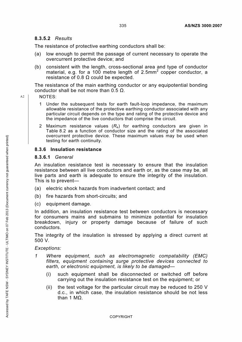
335 AS/NZS 3000:2007
COPYRIGHT
8.3.5.2 Results
The resistance of protective earthing conductors shall be:
(a) low enough to permit the passage of current necessary to operate the overcurrent protective device; and
(b) consistent with the length, cross-sectional area and type of conductor material, e.g. for a 100 metre length of 2.5mm2 copper conductor, a resistance of 0.8 Ω could be expected.
The resistance of the main earthing conductor or any equipotential bonding conductor shall be not more than 0.5 Ω.
NOTES:
1 Under the subsequent tests for earth fault-loop impedance, the maximum allowable resistance of the protective earthing conductor associated with any particular circuit depends on the type and rating of the protective device and the impedance of the live conductors that comprise the circuit.
2 Maximum resistance values (Re) for earthing conductors are given in Table 8.2 as a function of conductor size and the rating of the associated overcurrent protective device. These maximum values may be used when testing for earth continuity.
8.3.6 Insulation resistance
8.3.6.1 General
An insulation resistance test is necessary to ensure that the insulation resistance between all live conductors and earth or, as the case may be, all live parts and earth is adequate to ensure the integrity of the insulation. This is to prevent—
(a) electric shock hazards from inadvertent contact; and
(b) fire hazards from short-circuits; and
(c) equipment damage.
In addition, an insulation resistance test between conductors is necessary for consumers mains and submains to minimize potential for insulation breakdown, injury or property damage because of failure of such conductors.
The integrity of the insulation is stressed by applying a direct current at 500 V.
Exceptions:
1 Where equipment, such as electromagnetic compatability (EMC) filters, equipment containing surge protective devices connected to earth, or electronic equipment, is likely to be damaged—
(i) such equipment shall be disconnected or switched off before carrying out the insulation resistance test on the equipment; or
(ii) the test voltage for the particular circuit may be reduced to 250 V d.c., in which case, the insulation resistance should be not less than 1 MΩ.
A2
Acc
esse
d by
TA
FE
NS
W -
SY
DN
EY
INS
TIT
UT
E -
ULT
IMO
on
07 F
eb 2
013
(Doc
umen
t cur
renc
y no
t gua
rant
eed
whe
n pr
inte
d)

AS/NZS 3000:2007 336
COPYRIGHT
2 Where equipment, such as an RCD with an FE connection, is likely to influence the verification test—
(i) the FE connection shall be disconnected before carrying out the insulation resistance test on the equipment; or
(ii) the insulation resistance of the FE connection shall be not less than 0.05 MΩ, or as prescribed by the manufacturer.
The insulation resistance tester used shall be able to maintain its terminal voltage within +20% and -10% of the nominal open circuit terminal voltage, when measuring a resistance of 1 MΩ on the 500 V range or 10 MΩ on the 1000 V range.
8.3.6.2 Results
The insulation resistance between—
(a) the conductors of consumers mains and submains; and
(b) live and earthed parts of an electrical installation, or parts thereof, including consumers mains and submains
shall be not less than 1 MΩ.
Sheathed heating elements of appliances, RCDs with a functional earth connection and some other electrical equipment may cause test results lower than 1 MΩ. These should be disconnected from the circuit prior to testing.
Acceptable insulation resistance values for such items are—
(i) 0.01 MΩ for sheathed heating elements of appliances; or
(ii) value permitted in the Standard applicable to electrical equipment.
NOTE: Where consumers mains or submains are not of significant length, the insulation resistance of the circuit should be significantly greater than 1 MΩ, e.g. with short lengths (say 50 m) of polymeric cables, a value in excess of 50 MΩ would be expected.
8.3.7 Polarity
8.3.7.1 General
Polarity testing is necessary to ensure that no shock hazard arises from the incorrect connection of active, neutral and earthing conductors. This testing is to prevent—
(a) the transposition of active and neutral conductors of the consumers mains or submains supplying an outbuilding having an MEN connection, resulting in the electrical installation earthing system becoming energized; and
(b) combinations of incorrect active, neutral and earthing conductor connections resulting in the exposed conductive parts of the electrical installation becoming energized; and
Acc
esse
d by
TA
FE
NS
W -
SY
DN
EY
INS
TIT
UT
E -
ULT
IMO
on
07 F
eb 2
013
(Doc
umen
t cur
renc
y no
t gua
rant
eed
whe
n pr
inte
d)
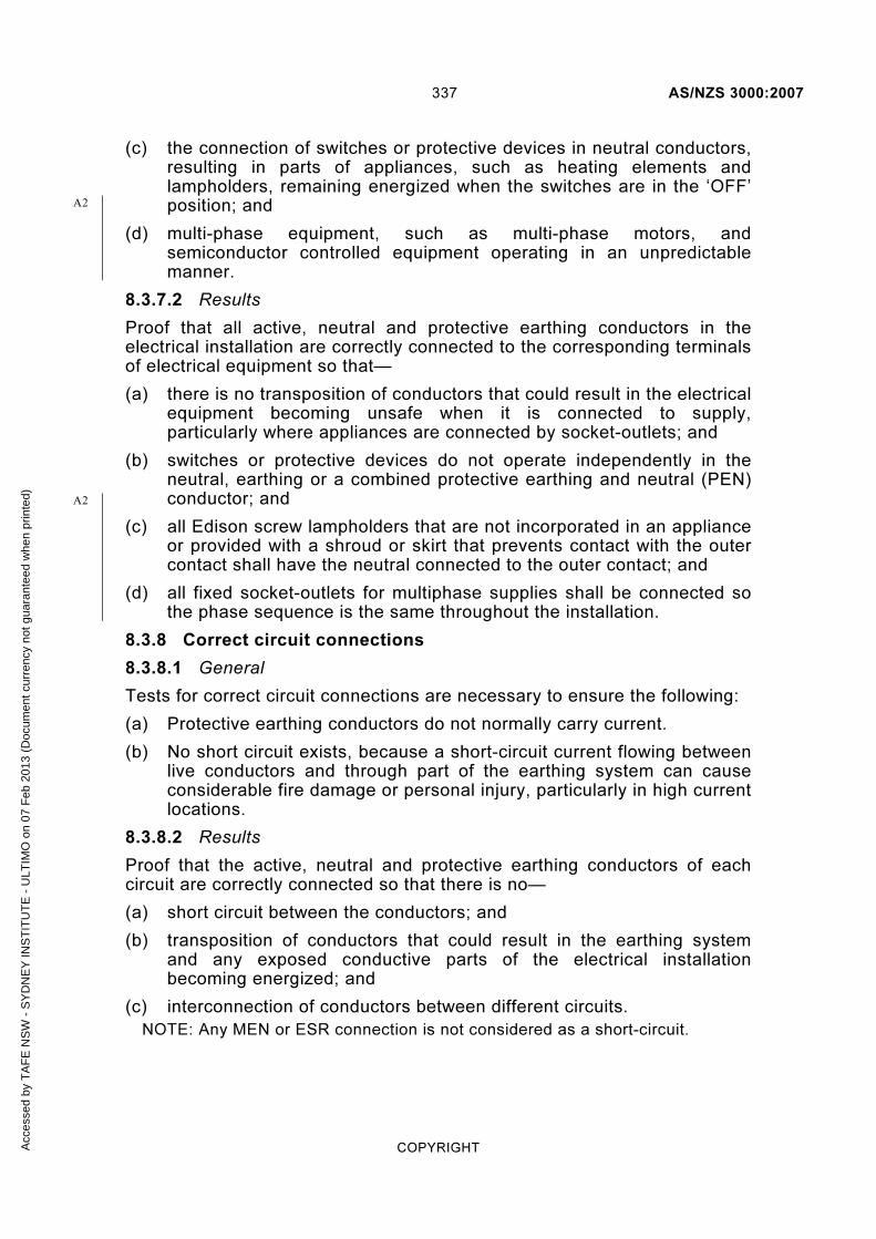
337 AS/NZS 3000:2007
COPYRIGHT
(c) the connection of switches or protective devices in neutral conductors, resulting in parts of appliances, such as heating elements and lampholders, remaining energized when the switches are in the ‘OFF’ position; and
(d) multi-phase equipment, such as multi-phase motors, and semiconductor controlled equipment operating in an unpredictable manner.
8.3.7.2 Results
Proof that all active, neutral and protective earthing conductors in the electrical installation are correctly connected to the corresponding terminals of electrical equipment so that—
(a) there is no transposition of conductors that could result in the electrical equipment becoming unsafe when it is connected to supply, particularly where appliances are connected by socket-outlets; and
(b) switches or protective devices do not operate independently in the neutral, earthing or a combined protective earthing and neutral (PEN) conductor; and
(c) all Edison screw lampholders that are not incorporated in an appliance or provided with a shroud or skirt that prevents contact with the outer contact shall have the neutral connected to the outer contact; and
(d) all fixed socket-outlets for multiphase supplies shall be connected so the phase sequence is the same throughout the installation.
8.3.8 Correct circuit connections
8.3.8.1 General
Tests for correct circuit connections are necessary to ensure the following:
(a) Protective earthing conductors do not normally carry current.
(b) No short circuit exists, because a short-circuit current flowing between live conductors and through part of the earthing system can cause considerable fire damage or personal injury, particularly in high current locations.
8.3.8.2 Results
Proof that the active, neutral and protective earthing conductors of each circuit are correctly connected so that there is no—
(a) short circuit between the conductors; and
(b) transposition of conductors that could result in the earthing system and any exposed conductive parts of the electrical installation becoming energized; and
(c) interconnection of conductors between different circuits.
NOTE: Any MEN or ESR connection is not considered as a short-circuit.
A2
A2
Acc
esse
d by
TA
FE
NS
W -
SY
DN
EY
INS
TIT
UT
E -
ULT
IMO
on
07 F
eb 2
013
(Doc
umen
t cur
renc
y no
t gua
rant
eed
whe
n pr
inte
d)

AS/NZS 3000:2007 338
COPYRIGHT
8.3.9 Verification of impedance (earth fault-loop impedance).
8.3.9.1 Socket-outlet circuits not protected by an RCD
Where an installation includes circuits containing socket-outlets not protected by an RCD, the impedance required for automatic disconnection of supply shall be verified on each such circuit by—
(a) verification of the total resistance (Rphe) of the active and protective earthing conductors; or
(b) where supply is available, verification of the earth fault-loop impedance,
in accordance with Clause 8.3.9.3.
Where supply is available, and the electrical installation is connected to a distribution system, the earth-fault loop impedance test is performed in order to verify the complete earth fault-loop, including the integrity of the MEN connection and the upstream neutral (PEN) conductors.
These tests shall be carried out in order to verify that the protective device will operate to disconnect an earth fault current within the time and touch voltage requirements of Clause 5.7.
NOTE: Further information on the maximum earth fault-loop impedance is contained in Table 8.1.
8.3.9.2 Results
The values obtained shall satisfy the requirements of Clause 5.7.4.
This requirement is deemed to be satisfied if—
(a) the total resistance (Rphe) of the active and protective earthing conductors of an individual circuit that forms part of the earth fault-loop does not exceed the value shown in Table 8.2 when tested in accordance with Clause 8.3.9.3 (a); or
(b) where supply is available, the earth fault-loop impedance, measured at a socket-outlet, does not exceed the value shown in Table 8.1, when tested in accordance with Clause 8.3.9.3 (b).
NOTES:
1 The values of Zs in Table 8.1 were calculated as shown in Paragraph B4.5.
2 The values in Table 8.2 were calculated using the d.c. resistance values for conductors at 20°C, as specified in AS/NZS 1125, and the maximum circuit lengths given in Table B1.
3 If an RCD operates during the test, the test result is considered satisfactory. However, such a result may not verify the MEN connection and upstream neutral conductors.
Acc
esse
d by
TA
FE
NS
W -
SY
DN
EY
INS
TIT
UT
E -
ULT
IMO
on
07 F
eb 2
013
(Doc
umen
t cur
renc
y no
t gua
rant
eed
whe
n pr
inte
d)

339 AS/NZS 3000:2007
COPYRIGHT
8.3.9.3 Method of measurement
(a) Supply not available Where supply is not available, the resistance of the conductors of each individual circuit may be measured by an ohmmeter as follows:
(i) Connect the active conductor and protective earthing conductor together at the origin of the particular circuit (normally where the protective device is fitted).
(ii) At the most distant point on the circuit, connect one lead of the ohmmeter to the active conductor and the other lead to the associated protective earthing conductor.
The measured value of resistance (Rphe) shall not exceed the value in Table 8.2 for the appropriate conductor size and type of protective device
(b) Supply available Where supply is available, the required impedance should be measured using an instrument that has a facility for measuring and indicating low values of impedance.
NOTE: Earth continuity and resistance tests should be carried out on protective earthing conductors in accordance with Clause 8.3.3 before measuring the earth fault-loop impedance.
The MEN connection is to be left intact.
Measurements should be carried out with the instrument connected between the most distant point on the active conductor and the corresponding point on the associated protective earthing conductor, at the socket-outlet.
NOTE: This test—
(a) verifies the integrity of the MEN connection and the upstream neutral
(PEN) conductors; and
(b) measures the value of Zs for the complete circuit; and
(c) should be performed in such a manner that the safety of the instrument
operator is not placed at risk.
Appropriate values of Zs are given in Table 8.1.
A1
Acc
esse
d by
TA
FE
NS
W -
SY
DN
EY
INS
TIT
UT
E -
ULT
IMO
on
07 F
eb 2
013
(Doc
umen
t cur
renc
y no
t gua
rant
eed
whe
n pr
inte
d)

AS/NZS 3000:2007 340
COPYRIGHT
TABLE 8.1
MAXIMUM VALUES OF EARTH FAULT-LOOP IMPEDANCE (Zs at 230 V)
Protective device rating
Circuit-breakers Fuses
Type B Type C Type D
Disconnection times
0.4 s 0.4 s 5 s
A Maximum earth fault-loop impedance Zs Ω
6 9.58 5.11 3.07 11.50 15.33
10 5.75 3.07 1.84 6.39 9.20
16 3.59 1.92 1.15 3.07 5.00
20 2.88 1.53 0.92 2.09 3.59
25 2.30 1.23 0.74 1.64 2.71
32 1.80 0.96 0.58 1.28 2.19
40 1.44 0.77 0.46 0.96 1.64
50 1.15 0.61 0.37 0.72 1.28
63 0.91 0.49 0.29 0.55 0.94
80 0.72 0.38 0.23 0.38 0.68
100 0.58 0.31 0.18 0.27 0.48
125 0.46 0.25 0.15 0.21 0.43
160 0.36 0.19 0.12 0.16 0.30
200 0.29 0.15 0.09 0.13 0.23
NOTE: Table 8.1 does not show 5 s disconnection times for circuit-breakers as the devices are intended to operate in the instantaneous tripping zone.
Acc
esse
d by
TA
FE
NS
W -
SY
DN
EY
INS
TIT
UT
E -
ULT
IMO
on
07 F
eb 2
013
(Doc
umen
t cur
renc
y no
t gua
rant
eed
whe
n pr
inte
d)

341 AS/NZS 3000:2007
COPYRIGHT
TABLE 8.2
MAXIMUM VALUES OF RESISTANCE
Conductor size
Protect-ive
device rating
Circuit breaker Fuses
Active Earth Type B Type C Type D
mm2 mm
2 A Maximum resistances
Rphe Rph Re Rphe Rph Re Rphe Rph Re Rphe Rph Re
1 1 6 6.14 3.07 3.07 3.28 1.64 1.64 1.96 0.98 0.98 7.36 3.68 3.68
1 1 10 3.68 1.84 1.84 1.96 0.98 0.98 1.18 0.59 0.59 4.10 2.05 2.05
1.5 1.5 10 3.68 1.84 1.84 1.96 0.98 0.98 1.18 0.59 0.59 4.10 2.05 2.05
1.5 1.5 16 2.30 1.15 1.15 1.22 0.61 0.61 0.74 0.37 0.37 1.96 0.98 0.98
2.5 2.5 16 2.30 1.15 1.15 1.22 0.61 0.61 0.74 0.37 0.37 1.96 0.98 0.98
2.5 2.5 20 1.84 0.92 0.92 0.98 0.49 0.49 0.58 0.29 0.29 1.34 0.67 0.67
4 2.5 25 1.48 0.57 0.91 0.78 0.30 0.48 0.47 0.18 0.29 1.05 0.40 0.65
4 2.5 32 1.15 0.44 0.71 0.62 0.24 0.38 0.37 0.14 0.23 0.82 0.32 0.50
6 2.5 40 0.92 0.27 0.65 0.49 0.14 0.35 0.30 0.09 0.21 0.61 0.18 0.43
10 4 50 0.74 0.21 0.53 0.39 0.11 0.28 0.24 0.07 0.17 0.46 0.13 0.33
16 6 63 0.59 0.16 0.43 0.32 0.09 0.23 0.19 0.05 0.14 0.36 0.10 0.26
NOTES:
1 The values, which have been rounded to two decimal places, are approximately 64% of the values given in Table 8.1. This is because of the following:
(a) A reduction to 80% (0.8) because of a conductor temperature of 20°C.
(b) A further reduction as the length of circuits given in Table B1 were calculated using 80% (0.8) of supply voltage. The further reduction assumes that 20% of the impedance is associated with the supply transformer. This should be taken into account if in doubt.
Therefore, 0.8 × 0.8 = 0.64 (64%).
2 Resistances for active conductors (Rph) and protective earthing conductors (Re) are also provided.
8.3.10 Operation of RCDs
NOTE: Supply must be available to perform this test.
8.3.10.1 Australia
Tests shall be performed on each final subcircuit protected by an RCD to verify that the RCD operates to disconnect the designated circuit.
In Australia, where supply is available, the function of the RCD shall be verified by the operation of the integral test device, or by the use of special test equipment.
A
A1
A1
Acc
esse
d by
TA
FE
NS
W -
SY
DN
EY
INS
TIT
UT
E -
ULT
IMO
on
07 F
eb 2
013
(Doc
umen
t cur
renc
y no
t gua
rant
eed
whe
n pr
inte
d)

AS/NZS 3000:2007 342
COPYRIGHT
NOTES:
1 Tripping the RCD by means of the integral test device establishes—
(a) the RCD is functioning correctly; and
(b) the integrity of the electrical and mechanical elements of the tripping device.
2 Operation of the integral test device does not provide a means of checking—
(a) the continuity of the main earthing conductor or the associated circuit protective earthing conductors; or
(b) any earth electrode or other means of earthing; or
(c) any other part of the associated electrical installation earthing.
8.3.10.2 New Zealand
Tests shall be performed on each final subcircuit protected by an RCD to verify that the RCD operates to disconnect the designated circuit.
In New Zealand the function of each RCD shall be verified by the—
(a) operation of the integral test device provided that manufacturer’s compliance documentation or equipment markings confirm that the RCD is intended to operate under residual alternating current and residual pulsating direct current conditions; or
NOTE: The RCD is a Type A RCD and is marked with the symbol .
(b) use of test equipment that causes the device to operate under residual alternating current and residual pulsating direct current conditions.
NOTES:
1 If the RCD being tested is marked with the symbol confirming that it is a Type A RCD, the residual direct pulsating current testing may be omitted.
2 The connection of test equipment to fixed wiring shall be restricted to supply connections made by a 3 pin plug connection into a socket with a purpose made tester connection cord.
3 A suitable test could be performed using a test plug with a resistor between the active and earth pins.
8.3.10.3 Results
The RCD shall disconnect the supply.
8.4 DATE OF INITIAL ENERGIZATION OF AN INSTALLATION
The date of initial energization or certification of an installation should be available on-site, either by marking or in an accessible record.
NOTE: In order to enable reverification, it is necessary to know the details of the original verification. This will facilitate the operation of a reverification regime, when instituted.
NZ
A1
A1
A2
Acc
esse
d by
TA
FE
NS
W -
SY
DN
EY
INS
TIT
UT
E -
ULT
IMO
on
07 F
eb 2
013
(Doc
umen
t cur
renc
y no
t gua
rant
eed
whe
n pr
inte
d)

343 AS/NZS 3000:2007
COPYRIGHT
APPENDIX A
REFERENCED DOCUMENTS
(Normative)
A1 NORMATIVE REFERENCES
The following are the normative documents referenced in this Standard:
AS 1883 Guide to maintenance and supervision of insulating oils in
service
2067 Switchgear assemblies and ancillary equipment for alternatingvoltages above 1 kV
3439 Low-voltage switchgear and controlgear assemblies 3439.4 Part 4: Low-voltage switchgear and controlgear assemblies—
Particular requirements for assemblies for construction sites (ACS)
3600 Concrete structures
3999(Ser) Thermal insulation of dwellings—Bulk insulation—Installation requirements
4702 Polymeric cable protection covers
4777 (Ser) Grid connection of energy systems via inverters
60269 Low-voltage fuses 60269.1 Part 1: General requirements (IEC 60269-1, Ed. 3.1 (2005)
IDT) 60269.3.1 Part 3.1: Supplementary requirements for fuses for use by
unskilled persons (fuses mainly for household andsimilar applications)—Sections I to IV: Examples of types of standardized fuses (IEC 60269-3-1, Ed. 2.0 (2004) IDT)
60529 Degrees of protection provided by enclosures (IP Code)(IEC 60529, Ed. 2.1 (2001) IDT)
60947 Low-voltage switchgear and controlgear60947.2 Part 2: Circuit-breakers (IEC 60947-2, Ed. 3.0 (2003) MOD)60947.4.1 Part 4.1: Contactors and motor-starters—Electromechanical
contactors and motor-starters (IEC 60947-4-1, Ed. 2.1 (2002) IDT)
60947.4.2 Part 4.2: Contactors and motor-starters—A.C. semiconductor motor controllers and starters
60947.8 Part 8: Control units for built-in thermal protection (PTC) for rotating electrical machines (IEC 60947-8, Ed. 1.0 (2003) IDT)
A2
A2
A2
A2
Acc
esse
d by
TA
FE
NS
W -
SY
DN
EY
INS
TIT
UT
E -
ULT
IMO
on
07 F
eb 2
013
(Doc
umen
t cur
renc
y no
t gua
rant
eed
whe
n pr
inte
d)

AS/NZS 3000:2007 344
COPYRIGHT
AS/NZS 2053 Conduits and fittings for electrical installations2053.2 Part 2: Rigid plain conduits and fittings of insulating material
2293 (Ser) Emergency escape lighting and exit signs for buildings 2293.1 Part 1: System design, installation and operation
2648 Underground marking tape2648.1 Part 1: Non-detectable tape
3001 Electrical installations—Transportable structures and vehicles including their site supplies
3002 Electrical installations—Shows and carnivals
3003 Electrical installations—Patient treatment areas of hospitals and medical, dental practices and dialyzing locations
3004 Electrical installations—Marinas and recreation boats 3004.1 Part 1: Marinas3004.2 Part 2: Recreational boats installations
3008 Electrical installations—Selection of cables—Cables for alternating voltages up to and including 0.6/1 kV
3008.1.1 Part 1.1: Typical Australian installation conditions 3008.1.2 Part 1.2: Typical New Zealand installation conditions
3010 Electrical installations—Generating sets
3012 Electrical installations—Construction and demolition sites
3013 Electrical installations—Classification of the fire and mechanical performance of wiring system elements
3015 Electrical installations—Extra-low voltage d.c. power supplies and service earthing within public telecommunications networks
3100 Approval and test specification—General requirements for electrical equipment
3111 Approval and test specification—Miniature overcurrent circuit-breakers
3112 Approval and test specification—Plugs and socket-outlets
3123 Approval and test specification—Plugs, socket-outlets and couplers for general industrial application
3131 Approval and test specification—Plugs and socket-outlets for stationary appliances
3133 Approval and test specification—Air break switches
3190 Approval and test specification—Residual current devices (current-operated earth-leakage devices)
3191 Electric flexible cords
3194 Approval and test specification—Electric shaver supply units
A1
A1
A2
A2
A2
Acc
esse
d by
TA
FE
NS
W -
SY
DN
EY
INS
TIT
UT
E -
ULT
IMO
on
07 F
eb 2
013
(Doc
umen
t cur
renc
y no
t gua
rant
eed
whe
n pr
inte
d)

345 AS/NZS 3000:2007
COPYRIGHT
AS/NZS 3439 Low-voltage switchgear and controlgear assemblies 3439.1 Part 1: Type-tested and partially type-tested assemblies (IEC
60439-1, Ed. 4.0 (1999) MOD) 3439.2 Part 2: Particular requirements for busbar trunking systems
(busways) (IEC 60439-2, Ed. 3.0 (2000) IDT) 3439.3 Part 3: Low-voltage switchgear and controlgear assemblies -
Particular requirements for low-voltage switchgear and controlgear assemblies intended to be installed inplaces where unskilled persons have access for theiruse - Distribution boards (IEC 60439-3:1990, MOD)
3439.5 Part 5: Particular requirements for assemblies intended to beinstalled outdoors in public places—Cable distribution cabinets (CDCs) for power distribution in networks(IEC 60439-5, Ed. 1.1 (1998) IDT)
3820 Essential safety requirements for low voltage electricalequipment
3832 Electrical installations—Cold-cathode illumination systems
3947 Low-voltage switchgear and controlgear 3947.3 Part 3: Switches, disconnectors, switch-disconnectors and
fuse-combination units (IEC 60947-2, Ed. 3.1 (2001) IDT)
4249 Electrical safety practices—Film, video and television sites
4296 Cable trunking systems
4396 Connectors—Insulation piercing—For 0.6/1 kV aerial bundled cables
4509 Stand-alone power systems4509.1 Part 1: Safety requirements4509.2 Part 2: System design
4763 (Int) Safety of portable inverters
5000 Electric cables—Polymeric insulated 5000.1 Part 1: For working voltages up to and including 0.6/1
(1.2) kV5000.2 Part 2: For working voltages up to and including 450/750 V
5033 Installation of photovoltaic (PV) arrays
5110 Recessed luminaire barriers
5601 Gas installations
7000 Overhead line design—Detailed procedures
60079(Ser) Explosive atmospheres60079.10.1 Part 10.1: Classification of areas—Explosive gas atmospheres 60079.10.2 Part 10.2: Classification of areas—Combustible dust
atmospheres 60079.14 Part 14: Electrical installations design, selection and erection 60079.17 Part 17: Electrical installations inspection and maintenance
A2
A2
Acc
esse
d by
TA
FE
NS
W -
SY
DN
EY
INS
TIT
UT
E -
ULT
IMO
on
07 F
eb 2
013
(Doc
umen
t cur
renc
y no
t gua
rant
eed
whe
n pr
inte
d)

AS/NZS 3000:2007 346
COPYRIGHT
AS/NZS
60335 Household and similar electrical appliances 60335.2.41 Part 2.41 Safety—Particular requirements for pumps 60335.2.76 Part 2.76: Safety—Particular requirements for electric fence
energizers (IEC 60335-2-76, Ed. 2.0 (2002) MOD) 60335.2.80 Part 2.80: Safety—Particular requirements for fans
(IEC 60335-2-80, Ed. 2.1 (2004) MOD)
60702 Mineral insulated cables and their terminations with a rated voltage not exceeding 750 V
60702.1 Part 1: Cables (IEC 60702-1, Ed. 3.0 (2002) IDT)
60898 Electrical accessories—Circuit-breakers for overcurrent protection for household and similar installations—Circuit-breakers for a.c. operation (IEC 60898, Ed. 1.2 (2003) MOD)
61008 Residual current operated circuit-breakers without integral overcurrent protection for household and similar uses (RCCBs)
61008.1 Part 1: General rules (IEC 61008-1, Ed. 2.1 (2002) MOD)
61009 Residual current operated circuit-breakers with integral overcurrent protection for household and similar uses (RCBOs)
61009.1 Part 1: General rules (IEC 61009-1, Ed. 2.1 (2003) MOD)
61058 Switches for appliances 61058.1 Part 1: General requirements
(IEC 61058-1, Ed. 3.0 (2001) MOD)
61535 Installation couplers 61535.1 Part 1: General requirements (IEC 61535-1, Ed. 1.0 (2004)
MOD)
61558 (Ser)
Safety of power transformers, power supply units and similar
IEC 60309 (Ser)
Plugs, socket-outlets and couplers for industrial purposes
60947 Low-voltage switchgear and controlgear 60947-3 Part 3: Switches, disconnectors, switch-disconnectors and
fuse-combination units
NZS 3104 Specification for concrete production
5261 Gas installation
AS/ACIF S009 Installation requirements for customer cabling (Wiring Rules)
ERA REPORT 69-30 Current rating standards for distribution cables69-30 Part III: Sustained current ratings for PVC-insulated cables69-30 Part V: Sustained current ratings for armoured cables with
thermo-setting insulation
A1
A2
Acc
esse
d by
TA
FE
NS
W -
SY
DN
EY
INS
TIT
UT
E -
ULT
IMO
on
07 F
eb 2
013
(Doc
umen
t cur
renc
y no
t gua
rant
eed
whe
n pr
inte
d)

347 AS/NZS 3000:2007
COPYRIGHT
New Zealand Ministry of Economic Development New Zealand Electricity Regulations
New Zealand Telecom New Zealand Telecommunications Carriers’ Forum—Premises
Wiring Code of Practice
A2 INFORMATIVE REFERENCES
The following documents are provided for information and guidance.
AS 1074 Steel tubes and tubulars for ordinary service
1319 Safety signs for the occupational environment
1359 Rotating electrical machines—General requirements
1418 Cranes, hoists and winches Set
1670 Fire detection, warning, control and intercom systems—System design, installation and commissioning
1735 (Ser) Lifts, escalators and moving walks
2118 Automatic fire sprinkler systems2118.1 Part 1: General requirements
2220 Rules for emergency warning and intercommunication systemsin buildings
2293 Emergency escape lighting and exit signs for buildings 2293.1 Part 1: System design, installation and operation
2419 Fire hydrant installations2419.1 Part 1: System design, installation and commissioning
2441 Installation of fire hose reels
2941 Fixed fire protection installations2941.1 Part 1: Pumpset systems
3818 Timber—Heavy structural products—Visually graded 3818.11 Part 11: Utility poles
3007 Electrical installations—Surface mines and associated processing plant
3007.2 Part 2: General protection requirements
3011 Electrical installations—Secondary batteries installed in buildings
3011.1 Part 1: Vented cells3011.2 Part 2: Sealed cells
4070 Recommended practices for protection of low-voltage electrical installations and equipment in MEN systems from transientovervoltages
4154 General access floors (elevated floors)
A2
A2
A2
A2
Acc
esse
d by
TA
FE
NS
W -
SY
DN
EY
INS
TIT
UT
E -
ULT
IMO
on
07 F
eb 2
013
(Doc
umen
t cur
renc
y no
t gua
rant
eed
whe
n pr
inte
d)
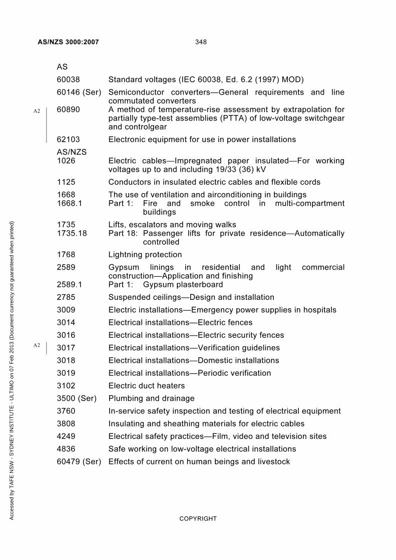
AS/NZS 3000:2007 348
COPYRIGHT
AS
60038 Standard voltages (IEC 60038, Ed. 6.2 (1997) MOD)
60146 (Ser) Semiconductor converters—General requirements and line commutated converters
60890 A method of temperature-rise assessment by extrapolation for partially type-test assemblies (PTTA) of low-voltage switchgear and controlgear
62103 Electronic equipment for use in power installations
AS/NZS 1026 Electric cables—Impregnated paper insulated—For working
voltages up to and including 19/33 (36) kV
1125 Conductors in insulated electric cables and flexible cords
1668 The use of ventilation and airconditioning in buildings 1668.1 Part 1: Fire and smoke control in multi-compartment
buildings
1735 Lifts, escalators and moving walks 1735.18 Part 18: Passenger lifts for private residence—Automatically
controlled
1768 Lightning protection
2589 Gypsum linings in residential and light commercial construction—Application and finishing
2589.1 Part 1: Gypsum plasterboard
2785 Suspended ceilings—Design and installation
3009 Electric installations—Emergency power supplies in hospitals
3014 Electrical installations—Electric fences
3016 Electrical installations—Electric security fences
3017 Electrical installations—Verification guidelines
3018 Electrical installations—Domestic installations
3019 Electrical installations—Periodic verification
3102 Electric duct heaters
3500 (Ser) Plumbing and drainage
3760 In-service safety inspection and testing of electrical equipment
3808 Insulating and sheathing materials for electric cables
4249 Electrical safety practices—Film, video and television sites
4836 Safe working on low-voltage electrical installations
60479 (Ser) Effects of current on human beings and livestock
A2
A2
Acc
esse
d by
TA
FE
NS
W -
SY
DN
EY
INS
TIT
UT
E -
ULT
IMO
on
07 F
eb 2
013
(Doc
umen
t cur
renc
y no
t gua
rant
eed
whe
n pr
inte
d)

349 AS/NZS 3000:2007
COPYRIGHT
AS/NZS 60598 Luminaires 60598.1 Part 1: General requirements and tests (IEC 60598-1 Ed. 6.0
(2003) MOD) 60598.2.2 Part 2.2: Particular requirements—Recessed luminaires
(IEC 60598-2-2 Ed. 2.0 (1996) MOD)
62040 (Ser) Uninterruptible power systems (UPS)
IEC 60038 Standard voltages
60287 Electric cables—Calculation of the current rating
60364 Low-voltage electrical installations 60364-4-41 Part 4-
41: Protection for safety—Protection against electric shock
60364-4-44 Part 4-44:
Protection for safety—Protection against voltage disturbances and electromagnetic disturbances
60364-4-473 Electrical installations of buildings—Part 4: Protection for safety—Chapter 47: Application of protective measures for safety—Section 473: Measures of protection againstovercurrent
60364-7-703 Electrical installations of buildings—Requirements for special installations or locations—Rooms and cabins containing sauna heaters
60598 Luminaires 60598-1 Part 1: General requirements and tests
IEC/TR 61200-413 Electrical installation guide—Clause 413. Explanatory notes to
measures of protection against indirect contact by automaticdisconnection of supply
62350 Guidance for the correct use of residual current-operated protective devices (RCDs) for household and similar use
NZS 3604 Timber framed buildings
4246 Energy efficiency—Installing insulation in residential buildings
4510 Fire hydrant systems for buildings
4512 Fire detection and alarm systems in buildings
4515 Fire sprinkler systems for residential occupancies
4517 Fire sprinkler systems for houses
4541 Automatic fire sprinkler systems
6110 Electrical installations—Floor and ceiling heating systems
A1
A2
A2
A2
Acc
esse
d by
TA
FE
NS
W -
SY
DN
EY
INS
TIT
UT
E -
ULT
IMO
on
07 F
eb 2
013
(Doc
umen
t cur
renc
y no
t gua
rant
eed
whe
n pr
inte
d)

AS/NZS 3000:2007 350
COPYRIGHT
BS 88 Low voltage fuses (all Parts)
SA HB 301 Electrical installations—Designing to the wiring rules
National Marine Safety Committee (Australia) NSCV National standard for commercial vesselsC 5B Part C: Design and construction—Section 5: Engineering—
Subsection 5B: Electrical
Legend Int Interim Standard Ser Series of Standards
Acc
esse
d by
TA
FE
NS
W -
SY
DN
EY
INS
TIT
UT
E -
ULT
IMO
on
07 F
eb 2
013
(Doc
umen
t cur
renc
y no
t gua
rant
eed
whe
n pr
inte
d)

351 AS/NZS 3000:2007
COPYRIGHT
APPENDIX B
CIRCUIT PROTECTION GUIDE
(Informative)
B1 SCOPE
This Appendix B provides an example of the general arrangement of electrical installation circuits and identifies the steps required to determine the essential circuit arrangements that affect conductor size and selection of protective devices.
Guidance is also provided on the following:
(a) Coordination of the characteristics of conductors and protective devices for protection against overload current.
(b) Automatic disconnection of supply to provide fault protection, including determination of maximum earth fault-loop impedance and maximum length of a circuit that will allow a protective device to operate within the specified disconnection time.
B2 CIRCUIT ARRANGEMENTS
The electrical installation is required to be arranged with an appropriate number of independent circuits to different parts, in accordance with Clause 2.2.1.1.
The most common distribution arrangement for a low-voltage electrical installation is radial branched distribution, an example of which is shown in Figure B1.
The steps that should be taken to ensure correct circuit arrangements are as follows:
(a) Determine the required current-carrying capacity, in accordance with the AS/NZS 3008.1 series, for circuit conductors dependent on the method of installation and the presence of external influences.
(b) Determine overcurrent requirements, in accordance with Clause 2.5. Overcurrent includes both overload currents and short-circuit currents (see Paragraph B3).
(c) Determine voltage drop requirements, in accordance with Clause 3.6.
NOTE: Guidance on the calculation of voltage drop is given in the AS/NZS 3008.1 series.
(d) Determine the automatic disconnection of supply requirements, in accordance with Clause 5.7 (see also Paragraphs B4 and B5).
Acc
esse
d by
TA
FE
NS
W -
SY
DN
EY
INS
TIT
UT
E -
ULT
IMO
on
07 F
eb 2
013
(Doc
umen
t cur
renc
y no
t gua
rant
eed
whe
n pr
inte
d)

AS/NZS 3000:2007 352
COPYRIGHT
Safety ser v ices c i rcu i ts( f i re, evacuat ion and l i f ts )
HV/LV supply transformer by—a) d istr ibutor where ex terna l to premises ; orb ) e i ther d istr ibutor or customer wi th in premises
Suppy to main swi tchboard by—a) d istr ibutor’s network; orb ) ser v ice l ine ; orc ) consumer mains
Distr ibut ion swi tchboard(mechanica l ser v ices )
D istr ibut ionswitchboard
Distr ibut ionswitchboard
Fina l subci rcu i tsto pumps, ch i l le rs etc.
F ina l subci rcu i tsto genera l l ight ing, power and etc.
Submains
Main swi tchboard
Submains
Genera l power, l ight ing etc
FIGURE B1 EXAMPLE OF CIRCUIT ARRANGEMENTS OF AN ELECTRICAL INSTALLATION (TO THREE LEVELS)
(Symbols are explained in Table J1.)
NOTE: Alternatives are permitted. However, this arrangement offers the following advantages:
(a) One circuit only will be shut down (by fuses or circuit-breakers) in case of a fault.
(b) Location of the fault is simplified.
(c) Maintenance or extensions to a circuit can be performed leaving the remainder of the electrical installation in service.
(d) Conductor sizes can be reduced at protective devices installed on switchboards to suit the decreasing demand towards the final subcircuits.
(e) Conversely, a fault occurring on one of the circuits from the main switchboard will shut down supply to all circuits of related downstream distribution boards.
A1
Acc
esse
d by
TA
FE
NS
W -
SY
DN
EY
INS
TIT
UT
E -
ULT
IMO
on
07 F
eb 2
013
(Doc
umen
t cur
renc
y no
t gua
rant
eed
whe
n pr
inte
d)

353 AS/NZS 3000:2007
COPYRIGHT
B3 PROTECTION AGAINST OVERCURRENT
B3.1 General
The term ‘overcurrent’ includes both overload current and short-circuit current.
The danger to the system from overload currents is that the temperature of conductors and their insulation will rise to levels at which the effectiveness of the insulation and its expected service life will be reduced.
Short-circuit currents may be up to several thousand times normal current and will cause overheating and mechanical stresses of conductors and associated connections.
NOTE: See Clause 2.5.4 and the AS/NZS 3008.1 series.
Clause 2.5.1 requires active conductors to be protected by one or more protective devices in the event of overload or short-circuit.
The protection of conductors by protective devices is shown graphically in Figure B2. The conductor is deemed to be protected if its damage curve, determined in accordance with Clause 2.5.4.5, is to the right of the time/current characteristic curve of the protective device.
Time /currentcharacter ist ic cur veof a c i rcu i t-breaker
T ime /currentcharacter ist iccur ve of a fuse
Damage cur veof a cable
CURRENT l
TIM
E t
FIGURE B2 TYPICAL OVERCURRENT PROTECTION OF CONDUCTORS
B3.2 Coordination between conductors and overload protective devices
B3.2.1 General
Clause 2.5.3 requires a protective device to interrupt overload currents and that the operating characteristics of such a device satisfies the following two conditions that are shown as Equations 2.1 and 2.2 of Clause 2.5.3.1:
IB ≤ IN ≤ IZ . . . 2.1
I2 ≤ 1.45 × IZ . . . 2.2
Where
Acc
esse
d by
TA
FE
NS
W -
SY
DN
EY
INS
TIT
UT
E -
ULT
IMO
on
07 F
eb 2
013
(Doc
umen
t cur
renc
y no
t gua
rant
eed
whe
n pr
inte
d)

AS/NZS 3000:2007 354
COPYRIGHT
IB = the current for which the circuit is designed, e.g. maximum demand.
IN = the nominal current of the protective device.
NOTE: For adjustable devices, the nominal current IN is the current setting selected.
IZ = the continuous current-carrying capacity of the conductor (see AS/NZS 3008.1 series).
I2 = the current ensuring effective operation of the protective device and may be taken as equal to either the—
(a) operating current in conventional time for circuit-breakers (1.45 IN); or
(b) fusing current in conventional time for fuses (1.6 IN for fuses in accordance with the AS/NZS 60269 series).
NOTE: The conditions of the equations are shown graphically in Figure B3.
Conductorrat ings
l2l
Character ist icof protect ivedev ices
l N F
uses
l N C
i rcu i t-
breakers
l ZlB
1.45 l Z
FIGURE B3 COORDINATION OF THE CHARACTERISTICS OF CONDUCTORS AND PROTECTIVE DEVICES
B3.2.2 Application
B3.2.2.1 General
As shown in Equations 2.1 and 2.2, a protective device functions correctly if its—
(a) nominal current IN is greater than the maximum load current IB but less than the maximum allowable current IZ for the circuit; and
(b) tripping current I2 setting is less than 1.45 IZ.
A1
Acc
esse
d by
TA
FE
NS
W -
SY
DN
EY
INS
TIT
UT
E -
ULT
IMO
on
07 F
eb 2
013
(Doc
umen
t cur
renc
y no
t gua
rant
eed
whe
n pr
inte
d)

355 AS/NZS 3000:2007
COPYRIGHT
B3.2.2.2 Protection by circuit-breakers
Standards, such as AS/NZS 60898, require the tripping current for circuit-breakers (I2 in Equation 2.2) to be less than 1.45 IN, therefore, the condition of Equation 2.2 will always be satisfied. For circuit-breakers 1.45 IN is known as the conventional tripping current.
B3.2.2.3 Protection by fuses
Fuses complying with the AS 60269 series have a conventional tripping current of 1.6 IN, therefore, to satisfy the conditions of Equation 2.2 the rating of such fuses should not exceed 0.9 IZ.
NOTE: The factor 0.9 is derived from 1.45/1.6.
B4 PROTECTION BY AUTOMATIC DISCONNECTION OF SUPPLY
B4.1 Application
This Paragraph B4 provides guidance on the application of—
(a) the disconnection times required for protection by automatic disconnection of supply; and
(b) the earthing system impedance (earth fault-loop impedance) requirements of Clause 5.7; and
(c) the earth fault-loop impedance test outlined in Clause 8.3.9.3.
B4.2 Principle
The principle of protection by automatic disconnection of supply is intended to prevent a person being subjected to a dangerous touch voltage for a time sufficient to cause organic damage, in the event of an insulation fault.
In order to meet this requirement, in the event of such a fault the circuit protective device must interrupt the resulting fault current sufficiently quickly to prevent the touch voltage persisting long enough to be dangerous.
It follows that this method of protection relies on the combination of two conditions—
(a) the provision of a conducting path, designated the ‘earth fault-loop’, to provide for circulation of the fault current; and
(b) the interruption of the fault current within a maximum time by an appropriate protective device. This maximum time depends on parameters, such as the highest touch voltage, the probability of a fault, and the probability of a person touching equipment during a fault. Acceptable limits of touch voltage and duration are based on a knowledge of the effects of electric current on the human body that are described in AS/NZS 60479.
A1
A1
Acc
esse
d by
TA
FE
NS
W -
SY
DN
EY
INS
TIT
UT
E -
ULT
IMO
on
07 F
eb 2
013
(Doc
umen
t cur
renc
y no
t gua
rant
eed
whe
n pr
inte
d)

AS/NZS 3000:2007 356
COPYRIGHT
Condition (a) requires the installation of protective earthing conductors connecting all exposed conductive parts of the electrical equipment supplied by the installation to an earthing system, thus forming the earth fault-loop as shown in Figure B5. The protective earthing conductors must be of appropriate size and installed in a sound and reliable manner, in accordance with Section 5 of this Standard.
Condition (b) requires the installation of protective devices with appropriate characteristics as specified in Section 2 of this Standard.
B4.3 Disconnection times
AS/NZS 60479 defines two components that permit the establishment of a relationship between the prospective touch voltage and its duration, that does not usually result in harmful physiological effects on any person subjected to that touch voltage.
These two components are—
(a) the effect on the human body of electrical currents of various magnitudes and durations flowing through the body; and
(b) the electrical impedance of the human body as a function of touch voltage.
Using the available information (as described in IEC/TR 61200-413), the required relationship between prospective touch voltage and disconnection time was derived for the normal situation as shown in Curve L of Figure B4.
Figure B4 has been reproduced from IEC/TR 61200-413 Figure C2 and shows the maximum duration that a person may be in contact with an exposed live part of a circuit for a range of touch voltages under normal conditions (Curve L).
Normal situations were identified as having the following general characteristics—
(i) dry locations; and
(ii) floor presenting significant resistance.
Particular situations, including damp or wet locations and those involving exposure to wet or bare skin, require that touch voltages must be further limited as shown by curve Lp. Damp situations are covered in Section 6 of this Standard.
A1
A1
Acc
esse
d by
TA
FE
NS
W -
SY
DN
EY
INS
TIT
UT
E -
ULT
IMO
on
07 F
eb 2
013
(Doc
umen
t cur
renc
y no
t gua
rant
eed
whe
n pr
inte
d)

357 AS/NZS 3000:2007
COPYRIGHT
10 000
1000
100
1010 100 1000
LP L
DU
RA
TIO
N,
ms
VOLTAGE, v L for normal conditions touch voltage limit 50 V
Lp for wet conditions touch voltage limit 25 V
FIGURE B4 MAXIMUM DURATION OF PROSPECTIVE 50 Hz TOUCH VOLTAGE (Reproduced from IEC/TR 61200-413 Figure C2)
These curves demonstrate that for normal conditions—
(A) a touch voltage of 50 V may be sustained by a person indefinitely, and
(B) a touch voltage of 100 V may not be sustained and must be disconnected.
The required disconnection time depends on environmental conditions and whether a person is likely to be in contact with exposed conductive parts at the time of the fault.
The protective device is selected so that the fault current, IA = Uo/Zs, ensures its operation in a time t not greater than the required time.
This requires the calculation of the earth fault-loop impedance, Zs, which is possible only if all the elements of the loop, including the source, are known.
Zs may be calculated if the live and protective earthing conductors are in close proximity to one another and are not separated by ferromagnetic material or it may be determined by measurement.
A1
Acc
esse
d by
TA
FE
NS
W -
SY
DN
EY
INS
TIT
UT
E -
ULT
IMO
on
07 F
eb 2
013
(Doc
umen
t cur
renc
y no
t gua
rant
eed
whe
n pr
inte
d)

AS/NZS 3000:2007 358
COPYRIGHT
Reactance may generally be ignored for conductors of 35 mm2 or less where the active and earthing conductors are in close proximity to one another. Thus, for such circuits, the current IA may be calculated using only conductor resistance by:
IA = UO/(RPE + RL) . . . B1
Where
UO = the nominal a.c. r.m.s. voltage to earth
RPE = the resistance of the protective earthing conductor from the reference point to the exposed conductive part
RL = the resistance of the phase (active) conductor from the reference point to the exposed conductive part.
A study was made of the influence of the variations in the different parameters on the value of the prospective touch voltage and the corresponding disconnection time.
These parameters are:
(1) The factor c that represents the proportion of the supply voltage available at the reference point during operation of the protective device. Depending on the circuit considered, this may vary between 0.6, e.g. a circuit very far from the source and 1.0, e.g. a circuit supplied directly from the source.
(2) The value m is the ratio of the cross-sectional area of the phase conductor compared to the cross-sectional area of the protective earthing conductor in the circuit considered.
The supply voltage UO that may vary within limits specified in AS 60038 in Australia, or IEC 60038 in New Zealand.
Using a mean value of 0.8 for the factor c and a ratio m of 1, values that exist in most final subcircuits, the prospective touch voltage UT for a circuit is given by:
UT = c UO m/ (1+m) = 0.8 × 230 × 1/2 = 92 V . . . B2
= 92 V
This touch voltage approximates to a time of 0.4 s, according to curve L of Figure B4.
Therefore, for hand-held equipment, the maximum disconnection time for a 230 V nominal a.c. r.m.s. voltage to earth shall not exceed 0.4 s.
Disconnection times not exceeding 5 s are permitted for circuits not directly supplying portable or hand-held equipment for the following reasons:
(aa) Faults in such circuits are less likely.
(bb) There is less likelihood of persons being in contact with equipment supplied by such circuits during a fault.
(cc) Equipment supplied by these circuits is usually not gripped and can therefore be released easily if a fault occurs.
A1
Acc
esse
d by
TA
FE
NS
W -
SY
DN
EY
INS
TIT
UT
E -
ULT
IMO
on
07 F
eb 2
013
(Doc
umen
t cur
renc
y no
t gua
rant
eed
whe
n pr
inte
d)

359 AS/NZS 3000:2007
COPYRIGHT
(dd) Touch voltages are not expected to exceed the values in accordance with Figure B4 for the time/touch–voltage relationship.
This time limit of 5 s does not imply intentional delayed operation of protective devices or touch voltages that are unsafe.
Where the conditions for protection by automatic disconnection of supply cannot be fulfilled by overcurrent protective devices, such protection may be provided by RCDs having a suitable tripping time. This may occur with circuits supplying socket-outlets, the length of which is unknown, or circuits of great length and small cross-sectional area thus having high impedance.
NOTE: Maximum disconnection times will vary for other operating voltages or installation conditions. In particular, lower values of disconnecting time and touch voltage may be required for damp situations or special installations, in accordance with the requirements of Sections 6 and 7 of this Standard.
B4.4 The earth fault-loop
The earth fault-loop in an MEN system comprises the following parts, starting and ending at the point of fault (see Figure B5):
(a) The protective earthing conductor, (PE), including the main earthing terminal/connection or bar and MEN.
(b) The neutral-return path, consisting of the neutral conductor, (N), between the main neutral terminal or bar and the neutral point at the transformer (the earth return path RG to RB has a relatively high resistance and may be ignored for an individual installation in an MEN system).
(c) The path through the neutral point of the transformer and the transformer winding.
(d) The active conductor as far as the point of the fault.
The earth fault-loop is normally regarded as consisting of the following two parts—
(i) conductors upstream or ‘external’ to the reference point; and
(ii) conductors downstream or ‘internal’ to the circuit from the reference point.
Figure B5 shows an active-to-earth fault which, for the purposes of calculations, is deemed to be of negligible impedance.
At the instant of the fault, current will flow through the earth fault-loop and its magnitude is only limited by the total system impedance Zs that is obtained from all the individual impedances in the earth fault-loop as follows:
Zs = ZAB + ZBC + ZCD + ZDE + ZEF + ZFG + ZGH + ZHA . . . B3
In Figure B5, impedances ZAB, ZBC, ZFG, ZGH and ZHA are all upstream of the protective device within the electrical installation under consideration and are regarded as being external to the reference point, hence, they may be collectively referred to as Zext. The remainder that are downstream (or ‘internal’) may be referred to as Zint, therefore, Zs = Zext + Zint.
Acc
esse
d by
TA
FE
NS
W -
SY
DN
EY
INS
TIT
UT
E -
ULT
IMO
on
07 F
eb 2
013
(Doc
umen
t cur
renc
y no
t gua
rant
eed
whe
n pr
inte
d)

AS/NZS 3000:2007 360
COPYRIGHT
This ratio is used to determine a suitable circuit length (see Paragraph B5).
MEN connect ionNeutra lbar
Ear th bar
L1
L2
L3N
Distr ibutor's network
Main swi tchboard
Mainear th ingconductor
Substat ion LVear th ing conductor
Distr ibutor's substat ion
Point of supply
Ser v ice l ine
Consumers mains
Soi l res istance betweene lectrodes re lat ive ly h igh.Propor t ion of currentmay be ignored.
Faul t y equipment
Faul t cur rent ( l A)A
C
DE
F
H
B G
RGRB
Rph
Re
Referencepoint
NOTE: Although supply from a distribution system is shown, the same principle applies where the substation forms part of the electrical installation.
FIGURE B5 MEN SYSTEM (SIMPLIFIED)—SHOWING FAULT CURRENT (Ia) PATH (EARTH FAULT-LOOP)
B4.5 Calculation of earth fault-loop impedance
Table 8.1 contains calculated examples of the maximum values of earth fault-loop impedance, Zs, using approximate mean tripping currents, which may be taken as IA for a limited range of MCBs (taken from AS/NZS 60898 and manufacturers’ time/current characteristic curves) and fuses (taken from AS 60269.1) and the appropriate disconnection time.
NOTES:
1 The appropriate tolerances permitted by the product Standard should be taken into consideration. Therefore, as part of the simplification process, approximate mean tripping currents have been used.
2 See Figure B6 for typical time/current curves for a circuit-breaker and a fuse.
3 Where the circuit protective device is an RCD, the calculation of earth fault-loop impedance is not necessary.
A2
Acc
esse
d by
TA
FE
NS
W -
SY
DN
EY
INS
TIT
UT
E -
ULT
IMO
on
07 F
eb 2
013
(Doc
umen
t cur
renc
y no
t gua
rant
eed
whe
n pr
inte
d)

361 AS/NZS 3000:2007
COPYRIGHT
CURRENT, l
TIM
E,
t
TIM
E,
t
( a ) C i rcu i t-breaker
CURRENT, l
( b ) Fuse
Range ofover loadprotect ion
Thermalre lease
Range ofshor t-c i rcu i tprotect ion
Range ofover loadprotect ion
Range ofshor t-c i rcu i tprotect ion
Magnet icre lease
FIGURE B6 TYPICAL TIME/CURRENT CURVES FOR CIRCUIT-BREAKERS AND FUSES
The values of Zs in Table 8.1 were calculated using the following equation:
Zs = Uo/Ia . . . B4
Where
Zs = earth fault-loop impedance
Uo = nominal phase voltage (230 V)
Ia = current causing automatic operation of the protective device, as follows:
Ia for circuit-breakers is the mean tripping current as follows:
Type B = 4 × rated current
Type C = 7.5 × rated current
Type D = 12.5 × rated current
Ia for fuses are approximate mean values from AS 60269.1.
B4.6 Earth fault-loop impedance measurement
Clause 8.3.9 requires an earth fault-loop impedance measurement test. The measured impedance should not exceed the value given for Zs in Table 8.1 for the appropriate protective device and disconnection time.
The earth fault-loop impedance should be measured using an instrument that has a facility for measuring and indicating low values of impedance.
The MEN connection is to be left intact.
Measurements can be made as follows:
(a) For a submain, where the instrument is connected between the relevant active conductor and the main earthing terminal/connection or bar at a switchboard.
A1
Acc
esse
d by
TA
FE
NS
W -
SY
DN
EY
INS
TIT
UT
E -
ULT
IMO
on
07 F
eb 2
013
(Doc
umen
t cur
renc
y no
t gua
rant
eed
whe
n pr
inte
d)
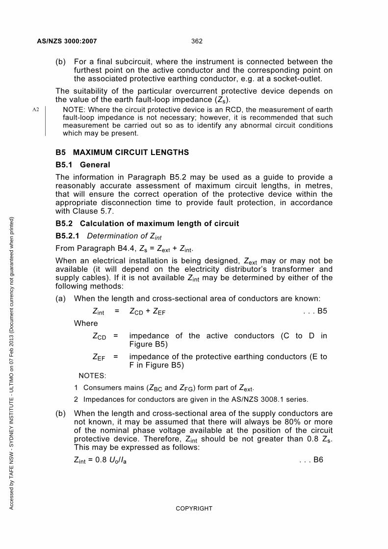
AS/NZS 3000:2007 362
COPYRIGHT
(b) For a final subcircuit, where the instrument is connected between the furthest point on the active conductor and the corresponding point on the associated protective earthing conductor, e.g. at a socket-outlet.
The suitability of the particular overcurrent protective device depends on the value of the earth fault-loop impedance (Zs).
NOTE: Where the circuit protective device is an RCD, the measurement of earth fault-loop impedance is not necessary; however, it is recommended that such measurement be carried out so as to identify any abnormal circuit conditions which may be present.
B5 MAXIMUM CIRCUIT LENGTHS
B5.1 General
The information in Paragraph B5.2 may be used as a guide to provide a reasonably accurate assessment of maximum circuit lengths, in metres, that will ensure the correct operation of the protective device within the appropriate disconnection time to provide fault protection, in accordance with Clause 5.7.
B5.2 Calculation of maximum length of circuit
B5.2.1 Determination of Zint
From Paragraph B4.4, Zs = Zext + Zint.
When an electrical installation is being designed, Zext may or may not be available (it will depend on the electricity distributor’s transformer and supply cables). If it is not available Zint may be determined by either of the following methods:
(a) When the length and cross-sectional area of conductors are known:
Zint = ZCD + ZEF . . . B5
Where
ZCD = impedance of the active conductors (C to D in Figure B5)
ZEF = impedance of the protective earthing conductors (E to F in Figure B5)
NOTES:
1 Consumers mains (ZBC and ZFG) form part of Zext.
2 Impedances for conductors are given in the AS/NZS 3008.1 series.
(b) When the length and cross-sectional area of the supply conductors are not known, it may be assumed that there will always be 80% or more of the nominal phase voltage available at the position of the circuit protective device. Therefore, Zint should be not greater than 0.8 Zs. This may be expressed as follows:
Zint = 0.8 Uo/Ia . . . B6
A2
Acc
esse
d by
TA
FE
NS
W -
SY
DN
EY
INS
TIT
UT
E -
ULT
IMO
on
07 F
eb 2
013
(Doc
umen
t cur
renc
y no
t gua
rant
eed
whe
n pr
inte
d)

363 AS/NZS 3000:2007
COPYRIGHT
B5.2.2 Calculation method
Equation B6 may be expressed in terms of circuit length by considering conductor sizes (active and earth) and protective device tripping current (see Note 1). This gives rise to the following equation:
( )pepha
pephomax
ρ
0.8
SSI
SSUL
+= . . . B7
Where
Lmax = maximum route length in metres—(see Table B1)
Uo = nominal phase volts (230 V)
ρ = resistivity at normal working temperature in Ω-mm2/m
= 22.5 × 10⁻³ for copper
= 36 × 10−3 for aluminium
Ia = trip current setting for the instantaneous operation of a circuit-breaker; or
= the current that assures operation of the protective fuse concerned, in the specified time
Sph = cross-sectional area of the active conductor of the circuit concerned in mm2
Spe = cross-sectional area of the protective earthing conductor concerned in mm2
NOTES:
1 Mean tripping currents, as outlined in Note 1 to Paragraph B4.5, are used for Ia.
2 This method is only reliable where the conductors that make up the earth-fault-current loop are in close proximity to each other and are not separated by ferromagnetic materials.
3 This calculation method is considered valid for cable sizes up to 120 mm2.
For larger sizes Zs should be calculated by other methods taking account of cable inductance.
B5.2.3 Guidance table
Table B1 contains typical maximum route lengths above which the impedance of the conductors could limit the magnitude of the short-circuit current to a level below that required to operate the protective device protecting the circuit in sufficient time to ensure safety against indirect contact.
The lengths were calculated using Equation B7 and the active and protective earthing conductor sizes outlined in the table.
A1
A1
Acc
esse
d by
TA
FE
NS
W -
SY
DN
EY
INS
TIT
UT
E -
ULT
IMO
on
07 F
eb 2
013
(Doc
umen
t cur
renc
y no
t gua
rant
eed
whe
n pr
inte
d)

AS/NZS 3000:2007 364
COPYRIGHT
TABLE B1
MAXIMUM ROUTE LENGTHS, IN METRES, FOR DIFFERENT SIZES OF CONDUCTORS AND PROTECTIVE
DEVICES USING APPROPRIATE MEAN TRIPPING CURRENTS (Ia)*
Conductor size Protective device rating
Circuit-breaker (see Note 1) Fuses (see
Note 2) Active
Earth
Type B Type C Type D
mm2 mm2 A Maximum route length, Lmax, m
1 1 6 170 91 55 204
1 1 10 102 55 33 114
1.5 1.5 10 153 82 49 170
1.5 1.5 16 96 51 31 82
2.5 2.5 16 160 85 51 136
2.5 2.5 20 128 68 41 93
4 2.5 25 126 67 40 90
4 2.5 32 98 52 31 70
6 2.5 40 90 48 29 60
10 4 50 117 62 37 73
16 6 63 142 76 45 85
16 6 80 112 59 36 59
25 6 80 124 66 40 66
25 6 100 99 53 32 47
35 10 100 159 85 51 75
35 10 125 127 68 41 58
50 16 125 198 106 63 90
50 16 160 155 83 50 71
70 25 160 235 126 75 108
70 25 200 188 100 60 84
* See B4.5 for values of Ia.
NOTES:
1 The types of circuit-breakers (Type B, C or D) are based on the types described in AS/NZS 60898.
2 Fuses based on AS/NZS 60269.1 are also known as BS 88 type fuses.
3 The maximum route lengths are the length of the phase conductor from the point of connection to the point of use and are related to a disconnection time of 0.4 s.
4 When the nominal phase voltage of the electrical installation is not 230 V, the maximum length may be determined by multiplying by a factor of Uo/230. For a nominal phase voltage of 240 V, the factor would be ~1.04.
5 Lengths of circuits may also be limited by voltage drop, particularly for single-phase arrangements.
A1
A1
A1
Acc
esse
d by
TA
FE
NS
W -
SY
DN
EY
INS
TIT
UT
E -
ULT
IMO
on
07 F
eb 2
013
(Doc
umen
t cur
renc
y no
t gua
rant
eed
whe
n pr
inte
d)

365 AS/NZS 3000:2007
COPYRIGHT
6 The maximum length obtained only satisfies the fault protection requirements of Clause 1.5.5.3. The overload, short-circuit and voltage drop requirements will need to be considered independently.
Acc
esse
d by
TA
FE
NS
W -
SY
DN
EY
INS
TIT
UT
E -
ULT
IMO
on
07 F
eb 2
013
(Doc
umen
t cur
renc
y no
t gua
rant
eed
whe
n pr
inte
d)

AS/NZS 3000:2007 366
COPYRIGHT
APPENDIX C
CIRCUIT ARRANGEMENTS
(Informative)
C1 SCOPE
This Appendix provides guidance on the following factors that determine the arrangement of circuits in an installation that would be deemed to meet the design, equipment selection and installation criteria of this Standard:
(a) Determination of the circuit current for consumers mains, submains and final subcircuits.
(b) Cable selection based on current-carrying capacity and voltage drop.
(c) Coordination of current ratings of circuit cables and protective devices.
(d) Division of installation into circuits supplying single and multiple items of equipment, as necessary, to provide satisfactory performance of circuits for purpose intended.
(e) Cable installation guides.
C2 MAXIMUM DEMAND
C2.1 After diversity maximum demand
As indicated in Clause 2.5 (and explained in Paragraph B3.2), the current in a circuit must not exceed the current rating of the circuit protective device, which, in turn, must not exceed the current-carrying capacity of the circuit conductors.
For circuits supplying a single item of equipment, the circuit current is simply the nominal load current of the equipment, e.g., a 10000 W 230/400 V three-phase heater has a full per–phase load current of 14.5 A. The circuit conductors and the protective device must have a current-carrying capacity of not less than 16 A (nearest standard rating).
Where more than one item of equipment is connected, the circuit current could be simply assessed as the sum of the individual equipment load currents. While this would provide a safe and conservative solution, it does not take account of the normal operating conditions during which all equipment is not operating simultaneously at full load or for long periods, e.g. submains to a distribution board associated with numerous socket-outlet circuits. Under such conditions the circuit current is estimated using diversity factors and is often described as the ‘after diversity maximum demand’.
The diversity factors applicable to any given circuit in an installation will depend on a number of features of the installation including—
(a) conditions under which the installation is expected to be used, e.g. residential compared with commercial; and
Acc
esse
d by
TA
FE
NS
W -
SY
DN
EY
INS
TIT
UT
E -
ULT
IMO
on
07 F
eb 2
013
(Doc
umen
t cur
renc
y no
t gua
rant
eed
whe
n pr
inte
d)

367 AS/NZS 3000:2007
COPYRIGHT
(b) operating characteristics of the connected load, e.g. airconditioning load in tropical locations compared with heating loads in cold-climate regions; and
(c) number and physical distribution of points provided on the circuit, e.g. socket-outlets provided for convenient connection of portable equipment compared to dedicated or fixed equipment loads; and
(d) size and type of significant loads, e.g. large motors or industrial plant.
It should be recognized that the determination of diversity factors is not accurate for every installation and different installations of the same type may have significantly different load profiles which the designer needs to consider. The methods provided herein have been used over several editions of AS/NZS 3000 and, provided that care is taken to assess the presence of unusual equipment loads, are considered appropriate for many typical applications.
When the load is assessed and the current-carrying capacity of the circuit is determined by allowing for diversity of operation of equipment, then the circuit should be protected by a circuit-breaker of rating to comply with Paragraph B3.2.
C2.2 Calculation of maximum demand in consumers mains and submains
As stated in Clause 2.2.2, maximum demand current can be determined by one of four methods—calculation, assessment, measurement or limitation. The following paragraphs of this Appendix provide information and examples on the application of the calculation method for determining maximum demand current in consumers mains and submains only.
C2.3 Domestic installations
C2.3.1 Method
Table C1 provides an allocation of load for different types of equipment connected to consumers mains or submains in a single or multiple domestic installation. The load current is calculated for each equipment load group in the installation or affected part thereof, and these contributions are added together to achieve the maximum demand current. The accompanying notes provide clarification of certain provisions and the examples demonstrate how the calculation is made.
Acc
esse
d by
TA
FE
NS
W -
SY
DN
EY
INS
TIT
UT
E -
ULT
IMO
on
07 F
eb 2
013
(Doc
umen
t cur
renc
y no
t gua
rant
eed
whe
n pr
inte
d)

CO
PY
RIG
HT
36
8
AS
/NZ
S 3
00
0:2
00
7
TABLE C1
MAXIMUM DEMAND—SINGLE AND MULTIPLE DOMESTIC ELECTRICAL INSTALLATIONS
1 2 3 4 5
Load group
Single domestic electrical installation
or individual living unit per phasea
Blocks of living unitsa,b,c
2 to 5 living units per
phase
6 to 20 living units per
phase
21 or more living units per phase
Loading associated with individual units
A. Lighting
(i) Except (ii) and load group H below d,e
3 A for 1 to 20 points + 2 A for each additional 20 points or part thereof
6 A
5 A + 0.25 A per living unit
0.5 A per living unit
(ii) Outdoor lighting exceeding a total of 1000 W f,g
75% connected load No assessment for the purpose of maximum demand
B.
(i) Socket-outlets not exceeding 10Ae,h. Permanently connected electrical equipment not exceeding 10 A and not included in other load groupsi
10 A for 1 to 20 points + 5 A for each additional 20
points or part thereof
10 A + 5 A per living unit
15 A + 3.75 A per living unit
50 A + 1.9 A per living unit
(ii) Where the electrical installation includes one or more 15 A socket-outlets, other than socket-outlets provided to supply electrical equipment set out in groups C,D, E, F, G, and Lh,j
10 A
(iii) Where the electrical installation includes one or more 20 A socket-outlets other than socket-outlets provided to supply electrical equipment set out in groups C, D, E, F, G, and Lh,j
15 A
(continued)
A2
Accessed by TAFE NSW - SYDNEY INSTITUTE - ULTIMO on 07 Feb 2013 (Document currency not guaranteed when printed)
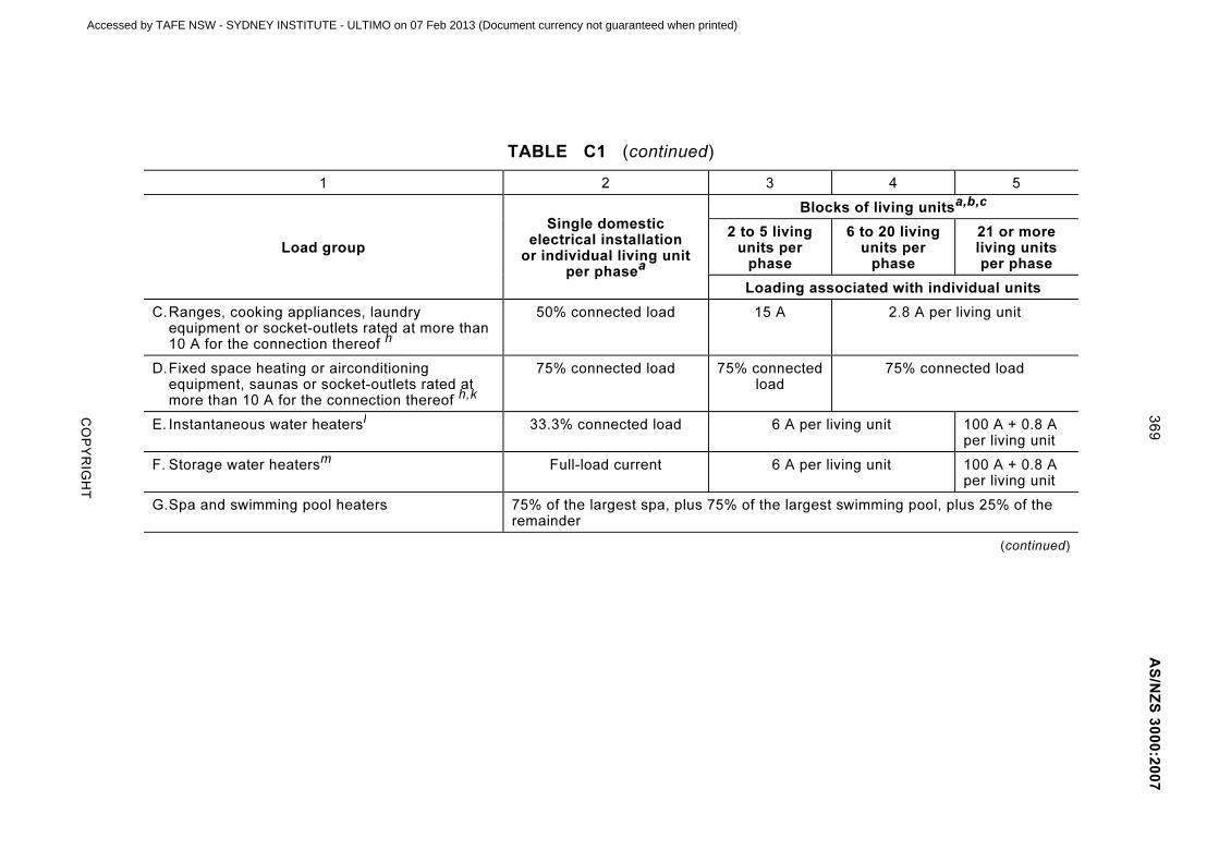
CO
PY
RIG
HT
36
9
AS
/NZ
S 3
00
0:2
00
7
TABLE C1 (continued)
1 2 3 4 5
Load group
Single domestic electrical installation
or individual living unit per phasea
Blocks of living unitsa,b,c
2 to 5 living units per
phase
6 to 20 living units per
phase
21 or more living units per phase
Loading associated with individual units
C. Ranges, cooking appliances, laundry equipment or socket-outlets rated at more than 10 A for the connection thereof h
50% connected load 15 A 2.8 A per living unit
D. Fixed space heating or airconditioning equipment, saunas or socket-outlets rated at more than 10 A for the connection thereof h,k
75% connected load 75% connected load
75% connected load
E. Instantaneous water heatersl 33.3% connected load 6 A per living unit 100 A + 0.8 A per living unit
F. Storage water heatersm Full-load current 6 A per living unit 100 A + 0.8 A per living unit
G. Spa and swimming pool heaters 75% of the largest spa, plus 75% of the largest swimming pool, plus 25% of the remainder
(continued)
Accessed by TAFE NSW - SYDNEY INSTITUTE - ULTIMO on 07 Feb 2013 (Document currency not guaranteed when printed)

CO
PY
RIG
HT
37
0
AS
/NZ
S 3
00
0:2
00
7
TABLE C1 (continued)
1 2 3 4 5
Load group Single domestic electrical installation
or individual living unit per phase
a
Loading not associated with individual units—connected to each phase (communal lighting, laundry loadings, lifts, motors, etc.)
H. Communal lightingf,g Not applicable Full connected load
I. Socket-outlets not included in groups J and M below h,j,n
.
Permanently connected electrical equipment not exceeding 10 A
Not applicable 2 A per point, up to a maximum of 15 A
J. Appliances rated at more than 10 A and socket-outlets for the connection thereof—
(i) Clothesdryers, water heaters, self-heating washing machines, wash boilers h
Not applicable 50% connected load
(ii) Fixed space heating, airconditioning
equipment, saunask
Not applicable 75% connected load
(iii) Spa and swimming pool heaters Not applicable 75% of the largest spa plus 75% of the largest swimming pool, plus 25% of the remainder
K. Lifts In accordance with Paragraph C2.4.1 and Table C2
In accordance with Paragraph C2.4.1 and Table C2
L. Motors In accordance with Paragraph C2.4.1,and Table C2, Column 2
In accordance with Paragraph C2.4.1 and Table C2, Column 2
M Appliances, including socket-outlets other than those set out in groups A to L above, e.g. pottery kilns, welding machines, radio transmitters, X-ray equipment and the like
Connected load 5 A or less: No assessment for purpose of maximum demand
Connected load 10 A or less: No assessment for purpose of maximum demand
Connected load over 5 A: By assessment
Connected load over 10 A: By assessment
A1
A2
Accessed by TAFE NSW - SYDNEY INSTITUTE - ULTIMO on 07 Feb 2013 (Document currency not guaranteed when printed)

371 AS/NZS 3000:2007
COPYRIGHT
NOTES TO TABLE C1: a See Clause 2.2.2 for where the maximum demand for consumers mains, and
submains, and final subcircuits, respectively, may be determined by assessment,
measurement or limitation. b For multiphase connections, divide the number of living units by the number of supply
phases, e.g. 16 units on a three-phase supply, 16/3 = 6 units on the heaviest loaded
phase (Column 4). c Where only a portion of the number of units in a multiple domestic electrical
installation is equipped with permanently connected or fixed appliances, such as
electric cooking ranges or space heating equipment, the number of appliances in each
category is divided over the number of phases, and the maximum demand determined
as shown in Example 3 of Paragraph C2.3.2. d Lighting track systems shall be regarded as two points per metre of track.
e A socket-outlet installed more than 2.3 m above a floor for the connection of a
luminaire may be included as a lighting point in load group A(i).
An appliance rated at not more than 150 W, which is permanently connected, or
connected by means of a socket-outlet installed more than 2.3 m above a floor, may
be included as a lighting point in load group A(i). f In the calculation of the connected load, the following ratings shall be assigned to
lighting:
(i) Incandescent lamps 60 W or the actual wattage of the lamp to be installed,
whichever is the greater, except that if the design of the luminaire associated
with the lampholder permits only lamps of less than 60 W to be inserted in any
lampholder, the connected load of that lampholder shall be the wattage of the
highest rated lamp that may be accommodated. For multi-lamp luminaires, the
load for each lampholder shall be assessed on the above basis.
(ii) Fluorescent and other discharge lamps Full connected load, i.e. the actual
current consumed by the lighting arrangement, including the losses of auxiliary
equipment, such as ballasts and capacitors.
(iii) Lighting tracks (230 V) 0.5 A/m per phase of track or the actual connected
load, whichever is the greater. g Floodlighting, swimming pool lighting, tennis court lighting and the like.
h For the purpose of determining maximum demand, a multiple combination
socket-outlet shall be regarded as the same number of points as the number of
integral socket-outlets in the combination. i Each item of permanently connected electrical equipment not exceeding 10 A may be
included in load group B(i) as an additional point. j Where an electrical installation contains 15 A or 20 A socket-outlets covered by load
group B(ii) or B(iii), the base loading of load group B is increased by 10 A or 15 A
respectively. If both 15 A and 20 A socket-outlets are installed, the increase is 15 A. k Where an electrical installation includes an airconditioning system for use in hot
weather and a heating system for use in cool weather, only the system that has the
greater load shall be taken into account. l Instantaneous water heaters including ‘quick recovery’ heaters having element ratings
greater than 100 W/L. m
Storage-type water heaters, including ‘quick recovery’ heaters not referred to in
footnote l. n This load group is not applicable to socket-outlets installed in communal areas but
connected to the individual living units. Such socket-outlets should be included in load
group B.
Acc
esse
d by
TA
FE
NS
W -
SY
DN
EY
INS
TIT
UT
E -
ULT
IMO
on
07 F
eb 2
013
(Doc
umen
t cur
renc
y no
t gua
rant
eed
whe
n pr
inte
d)

AS/NZS 3000:2007 372
COPYRIGHT
C2.3.2 Examples of calculation
NOTE: These examples were calculated assuming a supply voltage and electrical equipment rating of 230 V.
C2.3.2.1 Example 1
Determine the maximum demand of a single domestic electrical installation supplied at single-phase with the following load:
24 lighting points
10 m of lighting track
9 10 A single socket-outlets
8 10 A double socket-outlets
1 50 W exhaust fan
1 1 000 W strip heater
1 15 A socket-outlet
1 10000 W range
1 4800 W water heater
1 3000 W tennis court lighting
Solution
The method of determining demand in accordance with Table C1 is as follows:
Load group A(i)—
24 lighting points, plus
10 m of lighting track, plus
50 W exhaust fan = 45 points
= 3 + 2 + 2 = 7 A
Load group A(ii)—
3000 W tennis court lighting = 13 × 0.75 = 9.8 A
Load group B(i)—
9 × 10 A single socket-outlets, plus
8 × 10 A double socket-outlets = 25 points
1000 W strip heater = 1 point
= 10 + 5 = 15 A
Load group B(ii)—
15 A socket-outlet = 10 A
Load group C—
10000 W range = 43.48 × 0.5 = 21.7 A
Load group F—
Water heater 4800 W = 20.9 A
Acc
esse
d by
TA
FE
NS
W -
SY
DN
EY
INS
TIT
UT
E -
ULT
IMO
on
07 F
eb 2
013
(Doc
umen
t cur
renc
y no
t gua
rant
eed
whe
n pr
inte
d)

373 AS/NZS 3000:2007
COPYRIGHT
Total demand
= Sum of load group demands = A(i) + A(ii) + B(i) + B(ii) + C + F
= 7 + 9.8 + 15 + 10 + 21.7 + 20.9
= 84.4 A
C2.3.2.2 Example 2
Determine the maximum demand of the heaviest loaded phase in a domestic electrical installation comprising—
26 lighting points
24 10 A single-phase single socket-outlets
1 15 A single-phase socket-outlet
1 16600 W three-phase electric range consisting of two 5000 W hotplates and one 6600 W oven
1 4000 W single-phase airconditioning unit
1 12960 W three-phase instantaneous water heater
1 3600 W single-phase clothes dryer
and arranged for connection across a three-phase supply as follows:
Red White Blue
15 A socket-outlet 5000 W hotplate
4000 W airconditioner 4320 W instantaneous
water heater
15 × 10 A socket-outlets
5000 W hotplates
4320 W instantaneous water heater
3600 W clothes dryer
26 lights 9 ×10 A socket-outlets
6600 W oven
4320 W instantaneous water heater
Solution
The method of determining the demand in the heaviest loaded phase, in accordance with Table C1 is as follows:
Acc
esse
d by
TA
FE
NS
W -
SY
DN
EY
INS
TIT
UT
E -
ULT
IMO
on
07 F
eb 2
013
(Doc
umen
t cur
renc
y no
t gua
rant
eed
whe
n pr
inte
d)
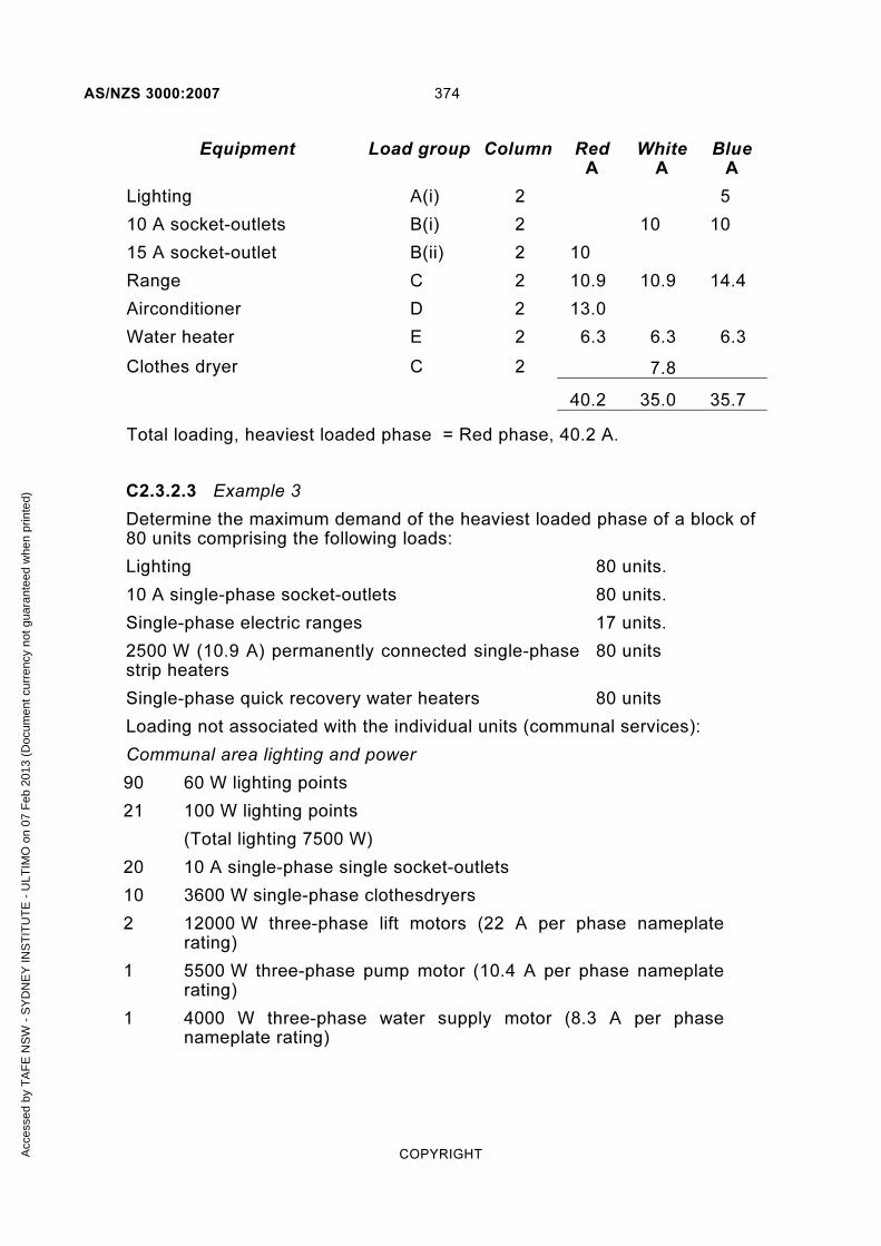
AS/NZS 3000:2007 374
COPYRIGHT
Equipment Load group Column Red A
White A
Blue A
Lighting A(i) 2 5
10 A socket-outlets B(i) 2 10 10
15 A socket-outlet B(ii) 2 10
Range C 2 10.9 10.9 14.4
Airconditioner D 2 13.0
Water heater E 2 6.3 6.3 6.3
Clothes dryer C 2 7.8
40.2 35.0 35.7
Total loading, heaviest loaded phase = Red phase, 40.2 A.
C2.3.2.3 Example 3
Determine the maximum demand of the heaviest loaded phase of a block of 80 units comprising the following loads:
Lighting 80 units.
10 A single-phase socket-outlets 80 units.
Single-phase electric ranges 17 units.
2500 W (10.9 A) permanently connected single-phase strip heaters
80 units
Single-phase quick recovery water heaters 80 units
Loading not associated with the individual units (communal services):
Communal area lighting and power
90 60 W lighting points
21 100 W lighting points
(Total lighting 7500 W)
20 10 A single-phase single socket-outlets
10 3600 W single-phase clothesdryers
2 12000 W three-phase lift motors (22 A per phase nameplate rating)
1 5500 W three-phase pump motor (10.4 A per phase nameplate rating)
1 4000 W three-phase water supply motor (8.3 A per phase nameplate rating)
Acc
esse
d by
TA
FE
NS
W -
SY
DN
EY
INS
TIT
UT
E -
ULT
IMO
on
07 F
eb 2
013
(Doc
umen
t cur
renc
y no
t gua
rant
eed
whe
n pr
inte
d)

375 AS/NZS 3000:2007
COPYRIGHT
Solution
The method of determining the demand of the heaviest loaded phase, assuming that the electrical installation is balanced as far as practicable over the three phases, in accordance with Table C1 is as follows:
Number of units per phase, three-phase supply = 80/3 = 27 units over each of two phases and 26 units on the other phase. The instructions given in Column 5 of Table C1 would therefore be applicable to the electrical installation other than for the electric ranges.
The number of electric ranges per phase = 17/3 = 6 over each of two phases and 5 on the other phase. The instructions in Column 4 of Table C1 would therefore be applicable to the load group C, ranges and cooking appliances.
Individual units (27 units)
Equipment Load group Column Calculation Result
Lighting A(i) 5 27 × 0.5 = 13.5 A
Socket-outlets B(i) 5 50 + (27 × 1.9) = 101.3 A
Electric ranges (6 units) C 4 6 × 2.8 = 16.8 A
Strip heaters D 5 27 × 10.9 × 0.75 = 220.7 A
Water heaters F 5 100 + (27 × 0.8) = 121.6 A
Total units loading for heaviest loaded phase = 473.9 A
Communal services The lighting is taken as being evenly balanced over the phases, i.e. 7500/3 = 2500 W per phase. (Should the lighting load be arranged for connection to one phase, the loading for load group H would be 7500 W.)
The 20 socket-outlets are taken as connected, 7 over each of two phases and 6 on the other phase.
The 10 clothesdryers are taken as connected, 3 over each of two phases and 4 on the other phase: loading on heaviest loaded phase = 14400 W.
The two 12000 W lift motors = 22 A per phase (nameplate rating)
Motors: 5500 W motor = 10.4 A per phase (nameplate rating)
4000 W motor = 8.3 A per phase (nameplate rating)
Acc
esse
d by
TA
FE
NS
W -
SY
DN
EY
INS
TIT
UT
E -
ULT
IMO
on
07 F
eb 2
013
(Doc
umen
t cur
renc
y no
t gua
rant
eed
whe
n pr
inte
d)

AS/NZS 3000:2007 376
COPYRIGHT
Equipment Load group Column Calculation Result
Lighting H 5
230
2500= 10.9 A
Socket-outlets I 5 7 × 2 = 14.0 A
Clothes dryers J(i) 5 ⎟⎠
⎞⎜⎝
⎛
230
144000.5 = 31.3 A
Lifts K 5 (22 × 1.25)
+ (22 × 0.75)
= 44.0 A
Motors L 5 10.4 + (8.3 × 0.5) = 14.6 A
Total communal services loading for heaviest loaded phase = 114.8 A
Total loading for heaviest loaded phase:
= units loading + communal services loading
= 473.9 + 114.8 = 588.7 A
C2.4 Non-domestic Installations
C2.4.1 Method
Table C2 provides an allocation of load for different types of equipment connected to consumers mains or submains in a non-domestic installation. The load current is calculated for each equipment load group in the installation, or affected part thereof, and these contributions are then added together to achieve the maximum demand current. The accompanying notes provide clarification of certain provisions and the examples demonstrate how the calculation is made.
A1
Acc
esse
d by
TA
FE
NS
W -
SY
DN
EY
INS
TIT
UT
E -
ULT
IMO
on
07 F
eb 2
013
(Doc
umen
t cur
renc
y no
t gua
rant
eed
whe
n pr
inte
d)

377 AS/NZS 3000:2007
COPYRIGHT
TABLE C2
MAXIMUM DEMAND —NON-DOMESTIC ELECTRICAL INSTALLATIONS
1 2 3
Load group
Residential institutions, hotels, boarding
houses, hospitals, accommodation houses, motels
a
Factories, shops, stores, offices,
business premises, schools and churches
a
A. Lighting other than in load group Fb,c
75% connected load Full connected load
B.
(i) Socket-outlets not exceeding 10 A other than those in B(ii)c,e
1000 W for first outlet plus 400 W for each additional outlet
1000 W for first outlet plus 750 W for each additional outlet
(ii) Socket-outlets not exceeding 10 A in buildings or portions of buildings provided with permanently installed heating or cooling equipment or bothc,d,e
1000 W for first socket-outlet, plus 100 W for each additional outlet
(iii) Socket-outlets exceeding 10 Ac,e
Full current rating of highest rated socket-outlet, plus 50% of full current rating of remainder
Full current rating of highest rated socket-outlet plus, 75% of full current rating of remainder
C. Appliances for cooking, heating and cooling, including instantaneous water heaters, but not appliances included in groups D and J below
Full connected load of highest rated appliance, plus 50% of full load of remainder
Full connected load of highest rated appliance, plus 75% of full load of remainder
D. Motors other than in E and F below
Full load of highest rated motor, plus 50% of full load of remainder
Full load of highest rated motor, plus 75% of full load of second highest rated motor, plus 50% of full load of remainder
E. Lifts (i) Largest lift motor —125% full load
(ii) Next largest lift motor —75% full load
(iii) Remaining lift motors —50% full load
For the purpose of this load group, the full-load current of a lift motor shall mean the current taken from the supply when lifting maximum rated load at maximum rated speed
F. Fuel dispensing units (i) Motors: First motor —full load
Second motor —50% full load
Additional motors —25% full load
(ii) Lighting —full connected load
(continued)
Acc
esse
d by
TA
FE
NS
W -
SY
DN
EY
INS
TIT
UT
E -
ULT
IMO
on
07 F
eb 2
013
(Doc
umen
t cur
renc
y no
t gua
rant
eed
whe
n pr
inte
d)

AS/NZS 3000:2007 378
COPYRIGHT
1 2 3
Load group
Residential institutions, hotels, boarding
houses, hospitals, accommodation houses, motels
a
Factories, shops, stores, offices,
business premises, schools and churches
a
G. Swimming pools, spas, saunas, thermal storage heaters including water heaters, space heaters, and similar arrangements
Full-load current
H. Welding machines In accordance with Paragraph C2.5.2, taking into account power factor correction
J. X-ray equipment 50% of the full load of the largest X-ray unit, additional units being ignored
K. Other equipment not covered by load groups above
By assessment
NOTES: a See Clause 1.6.3 for where the maximum demand for consumers mains, submains,
and final subcircuits, respectively, may be determined by assessment, measurement
or limitation. b In the calculation of the connected load, the following ratings shall be assigned to
lighting:
(i) Incandescent lamps 60 W or the actual wattage of the lamp to be installed,
whichever is the greater, except that if the design of the luminaire associated
with the lampholder permits only lamps of less than 60 W to be inserted in any
lampholder, the connected load of that lampholder shall be the wattage of the
highest rated lamp which may be accommodated. For multi-lamp luminaires, the
load for each lampholder shall be assessed on the above basis.
(ii) Fluorescent and other discharge lamps Full connected load, i.e. the actual
current consumed by the lighting arrangement, having regard to auxiliary
equipment, such as ballasts and capacitors.
(iii) Lighting tracks 0.5 A/m per phase of track or the actual connected load,
whichever is the greater. c A socket-outlet installed more than 2.3 m above a floor for the connection of a
luminaire may be included as a lighting point in load group A.
An appliance rated at not more than 150 W, which is permanently connected, or
connected by means of a socket-outlet installed more than 2.3 m above a floor, may
be included as a lighting point in load group A. d Load group B (ii) applies to an electrical installation, or portion of an electrical
installation, incorporating permanently installed heating and/or cooling equipment
specifically provided to render unnecessary the use of socket-outlets for portable
electric space heating or cooling appliances. Whether heating or cooling or both is
deemed necessary to avoid the use of portable heating or cooling equipment will
depend on the location and climate involved. e
For the purpose of determining maximum demand, a multiple combination
socket-outlet shall be regarded as the same number of points as the number of
integral socket-outlets in the combination.
TABLE C2 (continued)
Acc
esse
d by
TA
FE
NS
W -
SY
DN
EY
INS
TIT
UT
E -
ULT
IMO
on
07 F
eb 2
013
(Doc
umen
t cur
renc
y no
t gua
rant
eed
whe
n pr
inte
d)

379 AS/NZS 3000:2007
COPYRIGHT
C2.4.2 Examples of calculation
C2.4.2.1 Example 4
Determine the maximum demand of the heaviest loaded phase of a 30-unit motel complex supplied by three-phase with the following load:
200 60 W lighting points
30 50 W single-phase exhaust fans (permanently connected)
10 10 A single-phase single socket-outlets (non-permanently heated or cooled area)
90 10 A single-phase single socket-outlets (permanently heated or cooled area)
4 15 A single-phase socket-outlets
1 16600 W three-phase electric range consisting of two 5000 W hotplates and one 6600 W oven
1 750 W three-phase sewerage pump motor (2.0 A per phase nameplate rating)
1 6000 W single-phase sauna heater
The load is arranged for connection across the three-phase supply as follows:
Red White Blue
70 lights 10 exhaust fans
5 × 10 A socket-outlets B(i)
30 × 10 A socket-outlets B(ii)
1 × 15 A socket-outlet 6600 W oven 750 W pump
70 lights 10 exhaust fans
5 × 10 A socket-outlets B(i)
30 × 10 A socket-outlets B(ii)
2 × 15 A socket-outlets5000 W hotplates
750 W pump
60 lights 10 exhaust fans
30 ×10 A socket-outlets B(ii)
1 × 15 A socket-outlet 5000 W hotplates
750 W pump 6000 W sauna
Solution
The method of determining the demand in the heaviest loaded phase in accordance with Table C2, Column 2 is as follows:
A1
A2
Acc
esse
d by
TA
FE
NS
W -
SY
DN
EY
INS
TIT
UT
E -
ULT
IMO
on
07 F
eb 2
013
(Doc
umen
t cur
renc
y no
t gua
rant
eed
whe
n pr
inte
d)

AS/NZS 3000:2007 380
COPYRIGHT
Equipment Load group
Calculation Red A
White A
BlueA
70 light points A 70 x 60 W0.75
230×
13.7 13.7
60 light points A 60 x 60 W0.75
230×
11.74
10 exhaust fans
A Foot-note c
10 x 50 W0.75
230×
1.63 1.63 1.63
5 × 10 A socket-outlets
B(i) 2600 W1000 (4 400 W)
230+ × =
11.3 11.3
30 × 10 A socket-outlets
B(ii) 3900 W1000 (29 100 W)
230+ × =
16.96 16.96 16.96
1 × 15 A socket-outlet
B(iii) Full current rating 15.0 15.0
2 × 15 A socket-outlets
B(iii) 15 A + (15 A × 0.5) 22.5
6600 W oven C Full connected load 28.7
5000 W hotplate
C Full connected load 21.74 21.74
750 W sewer pump
D Full load (nameplate rating) 2.0 2.0 2.0
6000 W sauna heater
G Full-load current 26.09
89.29 89.83 95.16
Total loading, heaviest loaded phase = Blue phase, 95.16 A
C2.4.2.2 Example 5
Determine the maximum demand of the heaviest loaded phase of a factory electrical installation supplied by three-phase with the following load:
30 Twin 36 W power factor corrected fluorescent luminaires each with a run current of 0.42 A or as specified by the supplier
10 10 A single-phase single socket-outlets (non-permanently heated or cooled area)
4 10 A single-phase double socket-outlets (permanently heated or cooled area)
1 20 A single-phase socket-outlet
1 15 A single-phase socket-outlet
1 4000 W single-phase air conditioner
1 5500 W three-phase rolling machine motor (10.4 A per phase nameplate rating)
A2
Acc
esse
d by
TA
FE
NS
W -
SY
DN
EY
INS
TIT
UT
E -
ULT
IMO
on
07 F
eb 2
013
(Doc
umen
t cur
renc
y no
t gua
rant
eed
whe
n pr
inte
d)

381 AS/NZS 3000:2007
COPYRIGHT
1 4000 W three-phase lathe motor(8.3 A per phase nameplate rating)
1 3600 W single-phase storage water heater
2 250 A output three-phase arc welders (permanently connected) (10 A per phase primary current nameplate rating)
1 30000 VA two-phase spot welder (permanently connected)—varying operation (Paragraph C2.5.2.3(a)(i)) (50 A per phase primary current nameplate rating)
1 15000 VA two-phase spot welder (permanently connected)—specific operation at 20% duty cycle (Paragraph C2.5.2.3(a)(ii)) (25 A per phase primary current nameplate rating)
The load is arranged for connection across the three-phase supply as follows:
Red White Blue
15 lights 5 × 10 A
socket-outlets B(i)
3600 W water heater 15 A socket-outlet
5500 W rolling machine
4000 W lathe 250 A arc welder 250 A arc welder
15000 VA spot welder
4 x 10 A double socket-outlets B(ii)
20 A socket-outlet
5500 W rolling machine
4000 W lathe 250 A arc welder 250 A arc welder
30000 VA spot welder15000 VA spot welder
15 lights 5 × 10 A
socket-outlets B(i)
4000 W airconditioner5500 W rolling machine
4000 W lathe 250 A arc welder 250 A arc welder
30000 VA spot welder
Solution
The method of determining the demand in the heaviest loaded phase in accordance with Table C2, Column 3 is as follows:
Equipment Load group
Calculation Red
A
White
A
Blue
A
Lighting A 15 × 0.42 A 6.3 6.3
10 A socket-outlets
B(i) 4000 W1 000 (4 750 W)
230+ × = 17.39 17.39
10 A socket-outlets
(double)
B(ii) 1 700 W1000 (7 100 W)
230+ × =
7.39
20 A socket-outlet
B(iii) Full current rating 20.0
15 A socket-outlet
B(iii) Full current rating 15.0
A1
Acc
esse
d by
TA
FE
NS
W -
SY
DN
EY
INS
TIT
UT
E -
ULT
IMO
on
07 F
eb 2
013
(Doc
umen
t cur
renc
y no
t gua
rant
eed
whe
n pr
inte
d)

AS/NZS 3000:2007 382
COPYRIGHT
Equipment Load group
Calculation Red
A
White
A
Blue
A
4000 W airconditioner
C Full connected load 17.39
5500 W rolling machine
D Full load (nameplate rating) 10.4 10.4 10.4
4000 W lathe D 75% full load (nameplate rating) 0.75 × 8.3
6.2 6.2 6.2
3600 W water heater
G Full-load current 15.65
250 A output arc welder 250 A output arc welder
H
100% of rated primary current each (nameplate rating)—
Paragraph C2.5.2.2(b)(i)
10.0
10.0 10.0
10.0
10.0 10.0
30000 VA spot welder (varying operation, Paragraph C2.5.2.3(a)(i))
H Manually operated, non-automatic — 50% of the rated primary current (nameplate rating). 0.5 × 50 = 25 A Groups: Paragraph C2.5.2.3(b) Largest machine: full value obtained from Paragraph C2.5.2.3(a)(i)
25.0 25.0
15000 VA spot welder (Duty cycle 20% Paragraph C2.5.2.3(a)(ii))
H Multiplier for 20% duty cycle is 0.45 × actual primary current for duty cycle selected (nameplate) 0.45 × 25 = 11.25 A Groups: Paragraph C2.5.2.3(b) Other machines: 60% of value obtained from Paragraph C2.5.2.3(a)(ii) i.e. 0.6 × 11.25 = 6.8 6.8
97.74 95.79 102.68
Total loading, heaviest loaded phase = Blue phase, 102.68 A
C2.4.3 Alternative calculation method for non-domestic installations
An alternative method may also be used for commercial and light-industrial applications. This method is based on experience and energy consumption figures for different types of occupancy within installations.
A1
A1
Acc
esse
d by
TA
FE
NS
W -
SY
DN
EY
INS
TIT
UT
E -
ULT
IMO
on
07 F
eb 2
013
(Doc
umen
t cur
renc
y no
t gua
rant
eed
whe
n pr
inte
d)
383 AS/NZS 3000:2007
COPYRIGHT
The values shown in Table C3 depend on factors, such as the climate, occupancy hours and levels, energy management systems and the degree to which equipment is uniformly distributed in the affected area.
An example is provided to demonstrate how the energy demand figures are converted to demand current.
C2.4.4 Example of calculation
A tenancy submains supplies an office of 1500 m2 in a temperate location that uses a dedicated airconditioning plant with zonal electric reheat in cooler months. Table C3 gives a figure of 50 VA/m2 for general light and power and 50 VA/m2 for airconditioning. The total figure is 150 kVA (1500 m2 × 100 VA/m2) equates to approximately 217 A at a 230/400 V operating voltage.
Acc
esse
d by
TA
FE
NS
W -
SY
DN
EY
INS
TIT
UT
E -
ULT
IMO
on
07 F
eb 2
013
(Doc
umen
t cur
renc
y no
t gua
rant
eed
whe
n pr
inte
d)
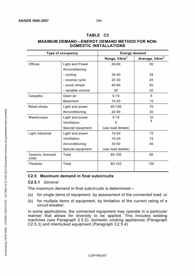
AS/NZS 3000:2007 384
COPYRIGHT
TABLE C3
MAXIMUM DEMAND—ENERGY DEMAND METHOD FOR NON-DOMESTIC INSTALLATIONS
Type of occupancy Energy demand
Range, VA/m2 Average, VA/m
2
Offices Light and Power
Airconditioning
- cooling
- reverse cycle
- zonal reheat
- variable volume
40-60
30-40
20-30
40-60
20
50
35
25
50
20
Carparks Open air
Basement
0-10
10-20
5
15
Retail shops Light and power
Airconditioning
40-100
20-40
70
30
Warehouses Light and power
Ventilation
Special equipment
5-15
5
(use load details)
10 5
Light industrial Light and power
Ventilation
Airconditioning
Special equipment
10-20
10-20
30-50
(use load details)
15
15
40
Taverns, licensed clubs
Total 60-100 80
Theatres Total 80-120 100
C2.5 Maximum demand in final subcircuits
C2.5.1 General
The maximum demand in final subcircuits is determined—
(a) for single items of equipment, by assessment of the connected load; or
(b) for multiple items of equipment, by limitation of the current rating of a circuit-breaker.
In some applications, the connected equipment may operate in a particular manner that allows for diversity to be applied. This includes welding machines (see Paragraph 2.5.2), domestic cooking appliances (Paragraph C2.5.3) and interlocked equipment (Paragraph C2.5.4)
Acc
esse
d by
TA
FE
NS
W -
SY
DN
EY
INS
TIT
UT
E -
ULT
IMO
on
07 F
eb 2
013
(Doc
umen
t cur
renc
y no
t gua
rant
eed
whe
n pr
inte
d)

385 AS/NZS 3000:2007
COPYRIGHT
C2.5.2 Welding machines
C2.5.2.1 Definitions
For the purpose of Paragraph C2.5.2, the following definitions apply:
(a) Rated primary current—
(i) for arc welding machines complying with the AS 1966 series, the marked rated input current, or the marked corrected primary current where fitted with power factor correction equipment; and
(ii) for all other welding machines, the current obtained by multiplying the rated kilovolt amperes (kVA) by 1000 and dividing by the rated primary voltage using the values given on the nameplate.
(b) Actual primary current The current drawn from the supply circuit during each welding operation at the particular heat tap and control setting used.
(c) Duty cycle The ratio of the time during which welding current flows to the standard period of 1 min, expressed as a percentage.
Example 1
A spot welder supplied by a 50 Hz system (3000 cycles/min) making six 15-cycle welds per minute would have a duty cycle of —
3% = 3000
100 15 6 ××
Example 2
A seam welder operating two cycles ‘ON’ and two cycles ‘OFF’ would have a duty cycle of 50%.
NOTE: The current-carrying capacity of the supply conductors necessary to limit the voltage drop to a value permissible for the satisfactory performance of welding machines may sometimes be greater than that required to prevent overheating of the conductors.
C2.5.2.2 Arc welding machines
The following applies to arc welding machines:
(a) Individual machine The maximum demand of an individual arc welding machine shall be deemed to be 100% of the rated primary current.
(b) Groups of machines The maximum demand of two or more arc welding machines shall be deemed to be as follows:
(i) Two largest welding machines: .......... 100% of each rated primary current; plus
(ii) Next largest welding machine: ........... 85% of the rated primary current; plus
(iii) Next largest welding machine: ........... 70% of the rated primary current; plus
Acc
esse
d by
TA
FE
NS
W -
SY
DN
EY
INS
TIT
UT
E -
ULT
IMO
on
07 F
eb 2
013
(Doc
umen
t cur
renc
y no
t gua
rant
eed
whe
n pr
inte
d)

AS/NZS 3000:2007 386
COPYRIGHT
(iv) All other welding machines: ............... 60% of the rated primary current.
C2.5.2.3 Resistance welding machines
The following applies to resistance welding machines:
(a) Individual machines The maximum demand for an individual resistance welding machine shall be deemed to be as follows:
(i) Varying operation 70% of the rated primary current for seam and automatically fed machines, and 50% of the rated primary current for manually operated, non-automatic machines.
(ii) Specific operation The product of the actual primary current and the multiplier given below for the duty cycle at which the welder will be operated under specific operating conditions for which the actual primary current and duty cycle are known and remain unchanged.
Duty cycle %: 50 40 30 25 20 15 10 7.5 ≤5.0
Multiplier: 0.71 0.63 0.55 0.50 0.45 0.39 0.32 0.27 0.22
(b) Groups of machines The demand for two or more resistance welding machines shall be deemed to be the sum of the values obtained in accordance with Item (a) for the largest welding machine supplied, and 60% of the values obtained in accordance with Item (a) for all other welding machines supplied.
C2.5.3 Domestic cooking appliances.
The maximum demand current for a final subcircuit connected to fixed or stationary, range, oven or hotplate installed in a domestic installation, may be less than the full connected load of the equipment.
Table C4 provides assessed maximum demand values that may be applied to a final subcircuit supplying—
(a) an individual appliance using the energy rating of the appliance; or
(b) more than one appliance, e.g. separate oven and hotplates using the total energy rating of the appliances.
TABLE C4
MAXIMUM DEMAND—DOMESTIC COOKING APPLIANCES
Appliance full-load energy rating per phase Assessed maximum
demand
Not greater than 5000 W 16 A
Greater than 5000 W but not greater than 8000 W 20 A
Greater than 8000 W but not greater than 10000 W 25 A
Greater than 10000 W but not greater than 13000 W 32 A
Greater than 13000 W 40 A
Acc
esse
d by
TA
FE
NS
W -
SY
DN
EY
INS
TIT
UT
E -
ULT
IMO
on
07 F
eb 2
013
(Doc
umen
t cur
renc
y no
t gua
rant
eed
whe
n pr
inte
d)

387 AS/NZS 3000:2007
COPYRIGHT
C2.5.4 Interlocked equipment
Where more than one item of equipment is connected to the same final subcircuit, but is interlocked so that only a limited number of items can be connected at one time, e.g. duty and stand-by arrangements, the maximum demand may be assessed from the combination of items that presents the highest simultaneous load.
C3 SIMPLIFIED PROTECTIVE DEVICE SELECTION
C3.1 Background
As indicated in Clause 3.4, the current-carrying capacity of cables is to be determined from the AS/NZS 3008.1 series. These Standards provide a comprehensive set of tables and calculation methods taking into account different cable/conductor types, installation methods and external influences.
For many typical and simple applications, the need to refer to AS/NZS 3008.1 may not be warranted and an alternative, albeit more conservative, approach may be determined by limiting the current that can be provided to the circuit by the selection of appropriately rated protective devices.
Tables C5 and C6 provide guidance on the selection of protective devices suitable for use with cables of cross-sectional area from 1 mm2 to 25 mm2, for single-phase and three-phase cable applications respectively, under a range of installation conditions.
A1
Acc
esse
d by
TA
FE
NS
W -
SY
DN
EY
INS
TIT
UT
E -
ULT
IMO
on
07 F
eb 2
013
(Doc
umen
t cur
renc
y no
t gua
rant
eed
whe
n pr
inte
d)

AS/NZS 3000:2007 388
COPYRIGHT
TABLE C5
SIMPLIFIED PROTECTIVE DEVICE SELECTION FOR CABLES FROM 1 mm2 TO 25 mm2 USED IN SINGLE-PHASE APPLICATIONS
Cable type: PVC insulated and sheathed cables, two-core and earth marked V-90
Cable cross-
sectional area
(mm2)
Protective device rating (In)
(A)
Unenclosed Enclosed
In air
In thermal insulation partially
surrounded
In thermal insulation completely surrounded
In air In ground
(See Note 3)
1 16 10 8 13 16
1.5 20 16 10 16 20
2.5 25 20 16 20 32
4 32 25 20 25 40
6 40 32 25 32 50
10 63 50 32 50 63
16 80 63 40 63 80
25 100 80 50 80 100
NOTES TO TABLES C5 AND C6
1 Protective device ratings (In) have been assigned to align with typical current-carrying
capacity (Iz) figures for flat and circular cables in AS/NZS 3008.1.1 for Australian
conditions. The same ratings can be conservatively applied to New Zealand
conditions.
2 Single-circuit installation methods have been provided to keep the table simple. De-
rating factors for groups of cables are not addressed, as it is presumed that circuits
will—
(a) be separated from each other; and
(b) operate below maximum current in lower ambient temperature; or
(c) for cables assigned normal ratings of 75°C, any increased temperature effects
from grouping will not raise cable temperature above 90°C.
3 Other cables and installation methods can be sourced from the AS/NZS 3008.1 series,
or conservatively compared with the protective device ratings for the following cable
installation conditions:
(a) Cables buried direct in the ground may be treated as enclosed in ground.
(b) Unenclosed or enclosed cables in air touching a surface may be treated as in
air.
A2
A2
Acc
esse
d by
TA
FE
NS
W -
SY
DN
EY
INS
TIT
UT
E -
ULT
IMO
on
07 F
eb 2
013
(Doc
umen
t cur
renc
y no
t gua
rant
eed
whe
n pr
inte
d)

389 AS/NZS 3000:2007
COPYRIGHT
(c) Cables lying on top of thermal insulation may be treated as in thermal insulation
partially surrounded.
(d) Cables passing through more than 300mm of thermal insulation may be treated
as in thermal insulation completely surrounded.
TABLE C6
SIMPLIFIED PROTECTIVE DEVICE SELECTION FOR CABLES FROM 1 mm2 TO 25 mm2 USED IN THREE-PHASE APPLICATIONS
Cable type: PVC insulated and sheathed cables, four-core and earth, marked V-90
Cable cross-
sectional area
(mm2)
Protective device rating (In)
(A)
Unenclosed Enclosed
In air
In thermal insulation partially
surrounded
In thermal insulation completely surrounded
In air In ground
1 13 10 6 13 16
1.5 16 13 8 16 20
2.5 20 16 10 20 25
4 32 20 16 25 32
6 40 32 20 32 40
10 50 40 25 40 50
16 63 50 32 63 63
25 80 63 40 80 80
NOTE: See Notes to Table C5.
A2
A2
A2
A2
Acc
esse
d by
TA
FE
NS
W -
SY
DN
EY
INS
TIT
UT
E -
ULT
IMO
on
07 F
eb 2
013
(Doc
umen
t cur
renc
y no
t gua
rant
eed
whe
n pr
inte
d)

AS/NZS 3000:2007 390
COPYRIGHT
C4 SIMPLIFIED VOLTAGE DROP
C4.1 Background
As indicated in Clause 3.6, the voltage drop in cables may be determined from the AS/NZS 3008.1 series. The Standard provides a comprehensive set of tables and calculation methods taking into account different cable/conductor types, operating temperatures and installation methods.
The basic formula used in the AS/NZS 3008.1 series is—
Vd = (L × I × Vc) /1000 . . . C1
Where
Vd = Actual voltage drop on circuit; in volts, V
L = Route length of circuit; in metres, m
I = Circuit current (usually maximum demand); in amperes, A
Vc = Cable voltage drop per ampere-metre length of the circuit; in millivolts per ampere-metre, mV/Am
Values of Vc are tabulated in the AS/NZS 3008.1 series
This formula can be made simpler to apply by expressing the resulting voltage drop in percentage terms, as this allows for the percentage voltage on each section, i.e. consumers mains, submains and final subcircuits, to be added together, regardless of whether it is single-phase or three-phase. When the voltage drop in a circuit is expressed as a percentage of the circuit operating voltage, the formula becomes—
%Vd = (100/Vo) × (L × I × Vc) /1000 . . . C2
or = (L × I × Vc)/(10 × Vo)
Where
%Vd = Actual voltage drop in circuit as a fraction of circuit-operating voltage; in percentage, %
Vo = Circuit-operating voltage; in volts, V
The above formula can be also be rewritten in favour of the usual factors that are known about a particular circuit. Its intended length and circuit-current as follows:
(L × I)/%Vd = (10 × Vo)/Vc
the units of which can be expressed as Am per %Vd
Acc
esse
d by
TA
FE
NS
W -
SY
DN
EY
INS
TIT
UT
E -
ULT
IMO
on
07 F
eb 2
013
(Doc
umen
t cur
renc
y no
t gua
rant
eed
whe
n pr
inte
d)

391 AS/NZS 3000:2007
COPYRIGHT
TABLE C7
VOLTAGE DROP—SIMPLIFIED METHOD
Cable conductor size Single-phase (230 V) circuit Three-phase (400 V) circuit
Am per %Vd Am per %Vd
1 mm2 45 90
1.5 mm2 70 140
2.5 mm2 128 256
4 mm2 205 412
6 mm2 306 615
10 mm2 515 1 034
16 mm2 818 1 643
25 mm2 1 289 2 588
35 mm2 1 773 3 560
50 mm2 2 377 4 772
70 mm2 3 342 6 712
95 mm2 4 445 8 927
Table C7 provides a simple tabulation of the terms (10 x Vo)/Vc developed using values for Vc from the AS/NZS 3008.1.1 series for common PVC/PVC cable types operating at 75°C, and 230 V and 400 V for single-phase and three-phase circuits respectively.
Where the conditions of route length and circuit current are known, Table C7 can be used to determine—
(a) the required cable size for a specified percentage voltage drop in the circuit; and
(b) the percentage voltage drop that a particular cable will provide.
Examples are provided to illustrate these operations.
Acc
esse
d by
TA
FE
NS
W -
SY
DN
EY
INS
TIT
UT
E -
ULT
IMO
on
07 F
eb 2
013
(Doc
umen
t cur
renc
y no
t gua
rant
eed
whe
n pr
inte
d)
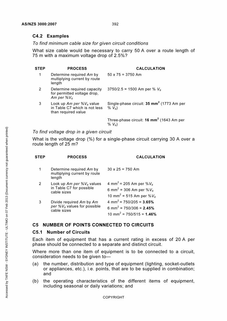
AS/NZS 3000:2007 392
COPYRIGHT
C4.2 Examples
To find minimum cable size for given circuit conditions
What size cable would be necessary to carry 50 A over a route length of 75 m with a maximum voltage drop of 2.5%?
STEP PROCESS CALCULATION
1 Determine required Am by multiplying current by route length
50 x 75 = 3750 Am
2 Determine required capacity for permitted voltage drop, Am per %Vd
3750/2.5 = 1500 Am per % Vd
3 Look up Am per %Vd value in Table C7 which is not less than required value
Single-phase circuit: 35 mm2 (1773 Am per
% Vd)
Three-phase circuit: 16 mm2 (1643 Am per
% Vd)
To find voltage drop in a given circuit
What is the voltage drop (%) for a single-phase circuit carrying 30 A over a route length of 25 m?
STEP
PROCESS CALCULATION
1 Determine required Am by multiplying current by route length
30 x 25 = 750 Am
2 Look up Am per %Vd values in Table C7 for possible cable sizes
4 mm2
= 205 Am per %Vd
6 mm2 = 306 Am per %Vd
10 mm2 = 515 Am per %Vd
3 Divide required Am by Am per %Vd values for possible cable sizes
4 mm2
= 750/205 = 3.65%
6 mm2 = 750/306 = 2.45%
10 mm2 = 750/515 = 1.46%
C5 NUMBER OF POINTS CONNECTED TO CIRCUITS
C5.1 Number of Circuits
Each item of equipment that has a current rating in excess of 20 A per phase should be connected to a separate and distinct circuit.
Where more than one item of equipment is to be connected to a circuit, consideration needs to be given to—
(a) the number, distribution and type of equipment (lighting, socket-outlets or appliances, etc.), i.e. points, that are to be supplied in combination; and
(b) the operating characteristics of the different items of equipment, including seasonal or daily variations; and
Acc
esse
d by
TA
FE
NS
W -
SY
DN
EY
INS
TIT
UT
E -
ULT
IMO
on
07 F
eb 2
013
(Doc
umen
t cur
renc
y no
t gua
rant
eed
whe
n pr
inte
d)

393 AS/NZS 3000:2007
COPYRIGHT
(c) the circuit current under expected operating conditions and the coordination with cable and protective device ratings to minimize the risk of an overload fault; and
(d) the effects of an overload fault on the circuit, including loss of supply to equipment that performs a special function, e.g. security, emergency, medical or critical information and telecommunications purposes.
Paragraph C5.2, together with the associated Tables, provides a method that has been used over several editions of AS/NZS 3000 and, provided that care is taken to assess the presence of unusual equipment loads, are considered appropriate for many typical applications.
C5.2 Final Subcircuits
Guidance on the determination of the number of socket-outlets, lighting and appliances, i.e. points, that may be connected to a final subcircuit is given in Table C8.
A1
Acc
esse
d by
TA
FE
NS
W -
SY
DN
EY
INS
TIT
UT
E -
ULT
IMO
on
07 F
eb 2
013
(Doc
umen
t cur
renc
y no
t gua
rant
eed
whe
n pr
inte
d)

CO
PY
RIG
HT
39
4
AS
/NZ
S 3
00
0:2
00
7
TABLE C8
GUIDANCE ON THE LOADING OF POINTS PER FINAL SUBCIRCUIT
Cable cross-
sectional area
a
(mm2)
Rating of circuit-
breakera
(A)
Contribution of each point
(A)
(sum must not exceed rating of circuit-breaker) Maximum connected load for a range
de
(W) Lighting points
f
10 A single or multiphase socket-outlets
cghi 15 A
single or multi-phase
socket-outlets
hi
20 A single or
multi-phase
socket-outlets
hi
Permanently connected
fixed or stationary
appliancesfj or
water heaters
Non-domestic installations
without permanent
airconditioning
All domestic installations and
non-domestic installations
with permanent airconditioning
1 6 0.5 NP NP NP NP Connected load NP
1 8 0.5 NP NP NP NP NP
1 10 0.5 NP NP NP NP NP
1 13 0.5 NP NP NP NP NP
1 16 0.5 NP NP NP NP NP
1.5 8 0.5 NP NP NP NP NP
1.5 10 0.5 NP NP NP NP NP
1.5 13 0.5 NP NP NP NP NP
1.5 16 0.5 NP NP NP NP 5000
1.5 20 0.5 NP NP NP NP 5000
2.5 10 0.5 NP NP NP NP NP
2.5 13 0.5 2 1 NP NP NP
2.5 16 0.5 2 1 15 NP 5000
2.5 20 0.5 2 1 12 20 8000
(continued)
Accessed by TAFE NSW - SYDNEY INSTITUTE - ULTIMO on 07 Feb 2013 (Document currency not guaranteed when printed)

CO
PY
RIG
HT
39
5
AS
/NZ
S 3
00
0:2
00
7
Cable cross-
sectional area
a
(mm2)
Rating of circuit-
breakera
(A)
Contribution of each point
(A)
(sum must not exceed rating of circuit-breaker) Maximum connected load for a range
de
(W) Lighting points
f
10 A single or multiphase socket-outlets
cghi 15 A
single or multi-phase
socket-outlets
hi
20 A single or
multi-phase
socket-outlets
hi
Permanently connected
fixed or stationary
appliancesfj or
water heaters
Non-domestic installations
without permanent
airconditioning
All domestic installations and
non-domestic installations
with permanent airconditioning
2.5 25 0.5 2 1 10 18 8000
2.5 32 0.5 2 1 8 16 10000
4 16 0.5 2 1 15 NP 5000
4 20 0.5 2 1 12 20 8000
4 25 0.5 2 1 10 18 10000
4 32 0.5 2 1 8 16 10000
6b
20 0.5 2 1 12 20 10000
6b
25 0.5 2 1 10 18 10000
6b
32 0.5 2 1 8 16 13000
10b
32 0.5 2 1 8 16 13000
10b
40 0.5 2 1 8 16 >13000
NP: Denotes socket-outlets not permitted on these circuits
TABLE C8 (continued)
Accessed by TAFE NSW - SYDNEY INSTITUTE - ULTIMO on 07 Feb 2013 (Document currency not guaranteed when printed)

AS/NZS 3000:2007 396
COPYRIGHT
NOTES TO TABLE C8
a Cable cross-sectional areas and protective device ratings relate directly to specified
installation methods given in Tables C5 and C6, e.g. a 2.5 mm2 cross-sectional area
cable used in conjunction with a 20 A protective device is recommended for use in
Table C5 for a single-phase circuit partially surrounded in thermal insulation or from
Table C6 for a three-phase circuit unenclosed in air. b Figures for 6 mm
2 and 10 mm
2 conductors are given primarily for dedicated circuits
supplying permanently connected fixed or stationary appliances, water heaters and
ranges. While this Standard does not prescribe the installation of socket-outlets and
lighting points on these circuits, the physical limitations of the terminals of these
devices may make their connection impractical. c For the purposes of determining the number of points, a multiple combination of
socket-outlets is regarded as the same number of points as the number of integral
socket-outlets in the combination. d A hotplate and oven are considered to be one cooking appliance if mounted within one
room. e
Maximum demand is limited by the circuit-breaker on the final subcircuit, which allows
for diversity in operation of the range elements and hotplates. f Lighting points A luminaire is deemed to comprise one or more lighting points,
according to the number of points at which it is connected by flexible cords to the
installation wiring, or according to the number of sections in which it is switched or
controlled. Connections of festoon lighting and decorative lighting shall not be
regarded as lighting points. See Table C1 for track systems and ELV lighting.
A socket-outlet installed more than 2.3 m above a floor for the connection of a luminaire may be included as a lighting point.
An appliance rated at not more than 150 W, which is permanently connected, or connected by means of a socket-outlet installed more than 2.3 m above a floor, may be included as a lighting point.
g Circuits with 10 A socket-outlets connected Applies where there are two or more
circuits in an electrical installation. h Restricted connections Table C8 precludes the connection of any socket-outlets on
conductors having a cross-sectional area less than 2.5 mm2, except where they are
used for the connection of a lighting point, or appliance rated at not more than 150 W
and installed more than 2.3 m above a floor (see f above). i The values are intended to be utilized when the final subcircuit is provided for general
use. Where it is known that socket-outlets may be used for specific items of electrical
equipment, such as dishwashers, room heaters or clothesdryers, the actual load of the
equipment should be substituted. j Fixed and stationary appliances Fixed and stationary appliances may be connected
permanently or through socket-outlets.
Acc
esse
d by
TA
FE
NS
W -
SY
DN
EY
INS
TIT
UT
E -
ULT
IMO
on
07 F
eb 2
013
(Doc
umen
t cur
renc
y no
t gua
rant
eed
whe
n pr
inte
d)

397 AS/NZS 3000:2007
COPYRIGHT
C6 GUIDE TO NUMBER OF CABLES INSTALLED IN CONDUITS
This information is intended to be used as a guide to determining the number of cables and circuits that may be installed, without damage, in conduits and other forms of wiring enclosure.
C6.1 Basis of calculations
The number of cables that can be installed in a circular conduit is determined from the ratios of the cross-sectional areas of the enclosure and the cable as follows:
factorspacecableofareasectionalcross
enclosureofareasectional-crossinternalcablesofNumber ×
−=
where the space factor recognises the reduction of space available from the circular geometry of the cables and enclosures:
For one cable in enclosure: ................................................................. 0.5
For two cables in enclosure: ............................................................... 0.33
For three or more cables in enclosure: ................................................ 0.4
Tables C9 to C11 demonstrate the application of the equation for combinations of common conduit and cable types.
C6.2 Application notes
Cable types and sizes used in Tables C9 to C11 are based on manufacturer’s catalogue nominal sizes for cables complying with AS/NZS 5000, Parts 1 and 2. For common building cable types, such as two-core and earth flat PVC/PVC V90 cables, the number of cables has increased because of the smaller cable dimensions of the 450/750V rated cables.
Conduit sizes and types used in Tables C9 to C11 are based on nominal bore dimensions determined from AS/NZS 2053 Parts 2 (rigid UPVC), Part 5 (corrugated) and Part 6 (profile wall smooth bore).
The calculation method can also be applied to other combinations of circular and non-circular enclosures, and cables of different types and sizes within the same enclosure, provided that the shape of the cables and enclosures are compatible.
The number of cables determined by the calculation assumes that the enclosure is relatively short in length, is clear of obstructions and distortions, and that the quantity and arrangement of impediments, such as bends, is minimized. Where this is not the case, the number of cables should be reduced and measures taken to ensure that the maximum cable pulling tension and bending radius are not exceeded.
The number of cables does not consider the effects of grouping cables on current-carrying capacity, temperature rise and voltage drop. AS/NZS 3008 provides de-rating factors for grouping that need to be considered in determining the suitability of circuits.
Acc
esse
d by
TA
FE
NS
W -
SY
DN
EY
INS
TIT
UT
E -
ULT
IMO
on
07 F
eb 2
013
(Doc
umen
t cur
renc
y no
t gua
rant
eed
whe
n pr
inte
d)

CO
PY
RIG
HT
39
8
AS
/NZ
S 3
00
0:2
00
7
TABLE C9
GUIDE TO THE MAXIMUM NUMBER OF SINGLE-CORE SHEATHED CABLES INSTALLED IN CONDUIT
Cable size
Heavy duty rigid UPVC conduit Corflo conduit Medium duty corrugated
Medium duty rigid UPVC conduit
20 25 32 40 50 63 80 80 100 100
125 150 100 100
125 150 20 25 32 40 16 20 25 32 40 50 (NZ) (AUS) (NZ) (AUS) (NZ) (AUS)
PVC/PVC V90
1 5 9 16 26 43 71 >100 >100 >100 >100 >100 >100 >100 >100 >100 >100 4 7 14 23 3 6 10 17 28 45
1.5 4 7 13 21 36 59 >100 >100 >100 >100 >100 >100 >100 >100 >100 >100 3 6 11 19 3 5 8 14 23 38
2.5 3 5 10 16 27 44 79 92 >100 >100 >100 >100 >100 >100 >100 >100 2 4 8 14 1 3 6 11 17 28
4 1 3 7 11 19 31 56 64 99 >100 >100 >100 99 >100 >100 >100 1 3 6 10 1 2 4 7 12 20
6 1 3 6 9 16 26 48 55 85 92 >100 >100 85 89 >100 >100 1 2 5 8 1 1 3 6 10 17
10 1 1 4 6 11 18 32 38 58 63 95 >100 58 60 90 >100 1 1 3 5 1 1 2 4 7 11
16 1 1 3 5 8 13 24 28 43 46 70 92 43 45 67 88 1 1 2 4 0 1 1 3 5 8
XLPE/PVC
25 0 1 1 3 5 9 16 19 29 31 48 62 29 30 45 60
35 0 1 1 2 4 7 13 15 24 26 39 52 24 25 38 50
50 0 1 1 1 3 6 10 12 19 21 31 41 19 20 30 40
70 0 0 1 1 2 4 8 9 15 16 24 31 15 15 23 30
95 0 0 1 1 1 3 6 7 11 12 18 24 11 12 17 23
120 0 0 0 1 1 2 5 6 9 10 15 20 9 10 14 19
150 0 0 0 1 1 2 4 5 7 8 12 16 7 8 12 16
185 0 0 0 0 1 1 3 4 6 6 10 13 6 6 10 13
240 0 0 0 0 1 1 2 3 5 5 8 10 5 5 7 10
300 0 0 0 0 1 1 1 2 4 4 6 8 4 4 6 8
400 0 0 0 0 0 1 1 1 3 3 5 7 3 3 5 6
500 0 0 0 0 0 1 1 1 3 3 4 6 3 3 4 6
630 0 0 0 0 0 0 1 1 1 2 3 4 1 1 3 4
A1
Accessed by TAFE NSW - SYDNEY INSTITUTE - ULTIMO on 07 Feb 2013 (Document currency not guaranteed when printed)

39
9
AS
/NZ
S 3
00
0:2
00
7
CO
PY
RIG
HT
TABLE C10
GUIDE TO THE MAXIMUM NUMBER OF TWO-CORE AND EARTH CABLES INSTALLED IN CONDUIT
Cable size
Heavy duty rigid UPVC conduit Corflo conduit Medium duty corrugated
Medium duty rigid UPVC conduit
20 25 32 40 50 63 80 80 100 100
125 150 100 100
125 150 20 25 32 40 16 20 25 32 40 50 (NZ) (AUS) (NZ) (AUS) (NZ) (AUS)
PVC/PVC V90
1.5 1 1 2 4 7 11 21 24 38 41 62 81 38 40 59 78 1 1 1 3 0 1 1 2 4 7
2.5 0 1 1 3 5 9 16 19 30 32 48 63 30 31 46 61 0 1 1 3 0 1 1 1 3 6
4 0 1 1 2 4 7 13 15 23 25 38 50 23 24 36 48 0 1 1 2 0 0 1 1 2 4
6 0 1 1 2 4 6 12 13 21 23 34 45 21 22 33 43 0 0 1 1 0 0 1 1 2 4
PVC/PVC V75
10 0 0 1 1 2 4 7 9 13 15 22 29 13 14 21 28 0 0 1 1 0 0 0 1 1 2
16 0 0 1 1 1 3 6 7 11 11 18 23 11 11 17 22 0 0 0 1 0 0 0 1 1 1
25 0 0 0 1 1 2 4 5 7 8 12 16 7 8 12 16 0 0 0 1 0 0 0 0 1 1
PVC/PVC V90
FLAT
1 1 2 5 8 14 23 42 48 75 81 >100 >100 75 78 >100 >100 1 2 4 7 1 1 3 5 9 15
1.5 1 2 5 8 13 22 40 46 71 77 >100 >100 71 74 >100 >100 1 2 4 7 1 1 3 5 9 14
2.5 1 1 3 5 9 15 28 32 50 54 81 >100 50 52 77 >100 1 1 3 5 1 1 1 3 6 10
4 1 1 2 4 6 11 20 23 36 38 58 76 36 37 55 73 0 1 1 3 0 1 1 2 4 7
6 0 1 1 3 5 9 17 19 30 32 49 64 30 31 47 62 0 1 1 3 0 1 1 2 3 6
10 0 1 1 2 4 7 12 14 22 24 36 47 22 23 34 45 0 1 1 1 0 0 1 1 2 4
16 0 0 1 1 2 4 8 9 14 15 23 31 14 15 22 30 0 0 1 1 0 0 0 1 1 2
A1
Accessed by TAFE NSW - SYDNEY INSTITUTE - ULTIMO on 07 Feb 2013 (Document currency not guaranteed when printed)

CO
PY
RIG
HT
40
0
AS
/NZ
S 3
00
0:2
00
7
TABLE C11
GUIDE TO THE MAXIMUM NUMBER OF FOUR-CORE AND EARTH CABLES INSTALLED IN CONDUIT
Cable size
Heavy duty rigid UPVC conduit Corflo conduit Medium duty corrugated
Medium duty rigid UPVC conduit
20 25 32 40 50 63 80 80 100 100
125 150 100 100
125 150 20 25 32 40 16 20 25 32 40 50 (NZ) (AUS) (NZ) (AUS) (NZ) (AUS)
PVC/
PVC V90
1.5 0 1 1 3 5 9 16 18 29 31 47 61 29 30 45 59 0 1 1 2 0 1 1 1 3 5
2.5 0 1 1 2 4 6 12 14 21 23 35 46 21 22 33 44 0 0 1 1 0 0 1 1 2 4
4 0 0 1 1 3 5 9 10 16 18 27 35 16 17 26 34 0 0 1 1 0 0 1 1 1 3
6 0 0 1 1 2 4 8 9 14 15 23 31 14 15 22 29 0 0 1 1 0 0 0 1 1 2
PVC/
PVC V75
10 0 0 0 1 1 2 5 6 9 10 15 20 9 10 14 19
0 0 0 0 1 1
16 0 0 0 1 1 1 4 4 7 8 12 15 7 7 11 15
0 0 0 0 1 1
25 0 0 0 0 1 1 3 3 5 5 8 11 5 5 8 11
0 0 0 0 0 1
35 0 0 0 0 1 1 2 2 4 4 7 9 4 4 6 9
50 0 0 0 0 0 1 1 1 3 3 5 6 3 3 5 6
70 0 0 0 0 0 1 1 1 2 2 4 5 2 2 3 5
95 0 0 0 0 0 0 1 1 1 1 3 4 1 1 2 3
XLPE/PVC
16 0 0 0 1 1 3 5 6 9 10 15 20 9 10 15 19
25 0 0 0 0 1 1 3 3 6 6 9 12 6 6 9 12
35 0 0 0 0 1 1 2 3 4 5 7 10 4 5 7 9
50 0 0 0 0 0 1 1 2 3 3 6 7 3 3 5 7
70 0 0 0 0 0 1 1 1 2 2 4 5 2 2 4 5
95 0 0 0 0 0 0 1 1 1 1 3 4 1 1 3 4
120 0 0 0 0 0 0 1 1 1 1 2 3 1 1 2 3
A1
Accessed by TAFE NSW - SYDNEY INSTITUTE - ULTIMO on 07 Feb 2013 (Document currency not guaranteed when printed)

401 AS/NZS 3000:2007
COPYRIGHT
APPENDIX D
MINIMUM SIZES OF POSTS, POLES AND STRUTS FOR AERIAL LINE CONDUCTORS
(Informative)
D1 GENERAL
The following Tables specify the sinking depth and sizes of support structures for private aerial lines.
The Tables in Appendix D apply to aerial conductor sizes up to 2 × 4 core 95 mm2 aluminium (Al) and 4 × 7/3.5 mm2 copper (Cu) only with a maximum total weight of 2.7 kg/m. AS/NZS 7000 can be used to determine the appropriate support structures for other conductor sizes and installation conditions not covered by these tables.
The types of conductor support structures specified in this Appendix are—
(a) timber posts and poles; and
(b) square timber struts; and
(c) angle iron struts; and
(d) steel poles; and
(e) steel square section; and
(f) fabricated steel poles.
Table D2 gives the forces exerted by the aerial conductor line. This is a function of—
(i) the type of conductor being used; and
(ii) the span length between supports; and
(iii) the design sag.
These factors combine to give the normal tension of an aerial conductor in kN. The last column of Table D2 indicates the minimum pole or strut strength required (S rating) to support the normal load applied by that tension.
Using this strength rating refer to Tables D3 to D13 to select the appropriately sized post, pole or strut. The S rating selected from Tables D3 to D13 must be equal to or greater than the required S rating derived from Table D2.
NOTES:
1 The free length to lowest conductor support shown in the Tables is the distance between the lowest conductor support and:
(a) the ground for a pole or post; or
(b) the closest fixing bolt on a structure for a strut.
A2
Acc
esse
d by
TA
FE
NS
W -
SY
DN
EY
INS
TIT
UT
E -
ULT
IMO
on
07 F
eb 2
013
(Doc
umen
t cur
renc
y no
t gua
rant
eed
whe
n pr
inte
d)

AS/NZS 3000:2007 402
COPYRIGHT
2 Galvanized steel-pipe posts with outside diameters up to and including 165 mm are Grade 250–steel water pipe commercially available in 6.5 m lengths. Posts specified with diameters of 168 mm must be Grade 350 structural steel circular hollow sections which may need to be specially ordered. Steel-pipe posts with a structural grade greater than 250 must be clearly marked with their tested strength grade.
D2 GENERAL REQUIREMENTS FOR POSTS AND POLES
Posts/poles must be securely set in the ground.
If the soil does not provide enough support, e.g. in built-up ground or soft soil, secure posts/poles either by setting them at a greater depth than normally required, or by using bearing blocks or shoes. Refer to Table D1 and its associated notes.
Where, because of unusual circumstances, the butt of the post/pole cannot be sunk to the required depth in the ground, an alternative construction, such as flange mounting on a reinforced concrete structure, may be suitable. In such cases, a structural engineer’s certification must be obtained certifying that the mounting is suitable for the installation.
The required length of the post/pole above ground must be assessed when selecting post/pole sizes to obtain necessary clearances.
TABLE D1
SINKING OF POSTS/POLES IN GROUND
Free length to lowest
Depth In ground (metres)
Conductor support (m)
Poor soil
Medium soil
Good soil
3.0 1.6 1.3 1.0
3.3 1.6 1.3 1.0
3.6 1.6 1.3 1.0
3.9 1.6 1.3 1.0
4.2 1.8 1.5 1.2
4.5 1.8 1.5 1.2
4.8 1.8 1.5 1.2
5.1 1.8 1.5 1.2
5.4 1.8 1.5 1.2
5.7 1.8 1.5 1.2
6.0 1.9 1.6 1.3
6.3 1.9 1.6 1.3
6.6 1.9 1.6 1.3
6.9 1.9 1.6 1.3
7.2 1.9 1.6 1.3
Acc
esse
d by
TA
FE
NS
W -
SY
DN
EY
INS
TIT
UT
E -
ULT
IMO
on
07 F
eb 2
013
(Doc
umen
t cur
renc
y no
t gua
rant
eed
whe
n pr
inte
d)

403 AS/NZS 3000:2007
COPYRIGHT
NOTES:
1 The free length to the lowest conductor support shown in Table D1 is the distance between the lowest conductor support and ground level.
2 Soil quality Soil quality is defined according to AS/NZS 7000.
(a) Poor—Soft clay, poorly compacted sand and soils that tend to absorb large amounts of water (150 kPa/m)
(b) Medium—Compact medium clay, well-bonded sandy loam, bonded sand and gravel with reasonable surface water drainage (300 kPa/m)
(c) Good—Well compacted rock soil, hard clay and well-bonded sand and gravel with good surface water drainage (600 kPa/m)
3 Posts/poles set in concrete Where a post/pole is set in concrete, it must be located centrally in a hole with a size corresponding to a minimum diameter of 100 mm greater than the diameter of the post/pole.
The concrete should be finished:
(a) not less than 250 mm below ground level for a wooden post/pole; or
(b) at 100 mm above ground level for a steel post/pole and shaped to shed water.
Setting the post/pole in concrete is equivalent to improving the soil quality by one step, i.e. from poor to medium or from medium to good. This corresponds to a reduction in the required sinking depth of the pole.
The post/pole should be left undisturbed for three days, or long enough to ensure that the concrete has developed adequate strength prior to attaching the aerial line.
4 Posts/poles set in solid rock Where a post/pole is set in solid rock, the depth in ground may be reduced by 0.3 m.
D2.1 Timber posts/poles
Timber posts and poles must be of hardwood or other suitable timber as specified by AS 3818.11.
Tables D3, D5 and D6 set out the minimum sizes of timber posts or poles of untreated hardwood timber with durability of Class 1 and 2 and strength rating of S3 or better.
The base of timber posts/poles and surrounding ground must be treated against insect and fungal attack by environmentally approved methods.
Timber posts/poles must be capped at the top to prevent water penetration.
The distance between the top anchor bolt and the top of the post/pole must not be less than 200 mm.
D2.2 Steel-pipe posts/poles
The required sizes/grades of steel-pipe posts/poles are set out in Tables D9 to D13 with Figure D1 showing how the tables are applied.
NOTE: Hollow steel poles must be capped at the top to prevent water penetration.
A1
A2
A2
Acc
esse
d by
TA
FE
NS
W -
SY
DN
EY
INS
TIT
UT
E -
ULT
IMO
on
07 F
eb 2
013
(Doc
umen
t cur
renc
y no
t gua
rant
eed
whe
n pr
inte
d)

AS/NZS 3000:2007 404
COPYRIGHT
Free length to lowestconductor suppor t( Tables D3, D5, D6
and D10 to D13 )= min imum he ight
above ground+ max imum sag
Depth in ground(Table D1)
Max imum span forcable t ype and s ize
( Table 3.9 )
Min imum pole /post length= min imum he ight
above ground+ Max imum sag
+ depth in ground+ 0.2 m
Maximum sag(Table D2)
Min imum height aboveground ( Table 3.8 )
Pole /post s izeand strength rat ing(Tables D3, D5, D6and D10 to D13 )
0.2 m
FIGURE D1 GUIDE TO SELECTION OF POLES/POSTS
D3 ATTACHMENTS TO BUILDINGS OR STRUCTURES
D3.1 Responsibility for design
The support must be designed and installed using sound engineering practice. It must be suitable for the direction of pull. If necessary the services of a structural engineer should be sought where doubt exists as to the strength of an attachment.
D3.2 Horizontal and vertical struts
A strut is a straight length of support. Once it is bent, offset or braced it is then classed as a bracket.
The strength rating of struts is set out in Table D2. The sizes of horizontal and vertical struts are set out in Tables D4, D7 and D8 with Figure D2 showing how the Tables are applied.
NOTE: Timber or hollow steel struts must be capped at the top to prevent water penetration.
Two fixing bolts must be used at a minimum distance of 600 mm apart to fix the strut to a structure.
A1
Acc
esse
d by
TA
FE
NS
W -
SY
DN
EY
INS
TIT
UT
E -
ULT
IMO
on
07 F
eb 2
013
(Doc
umen
t cur
renc
y no
t gua
rant
eed
whe
n pr
inte
d)
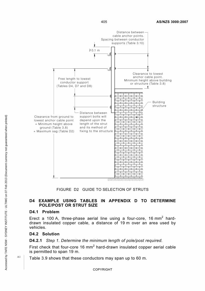
405 AS/NZS 3000:2007
COPYRIGHT
Clearance to lowestanchor cable point.
Min imum he ight above bui ld ingor structure ( Table 3.8 )
D istance betweencable anchor po ints.
Spacing between conductorsuppor ts ( Table 3.10 )
D istance betweensuppor t bo l ts wi l ldepend upon thelength of the strutand i ts method off ix ing to the structure
Free length to lowestconductor suppor t
( Tables D4, D7 and D8 )
Clearance f rom ground tolowest anchor cable point= Min imum height above
ground ( Table 3.8 )+ Max imum sag ( Table D2)
Bui ld ingstructure
0.1 m
FIGURE D2 GUIDE TO SELECTION OF STRUTS
D4 EXAMPLE USING TABLES IN APPENDIX D TO DETERMINE POLE/POST OR STRUT SIZE
D4.1 Problem
Erect a 100 A, three-phase aerial line using a four-core, 16 mm2 hard-drawn insulated copper cable, a distance of 19 m over an area used by vehicles.
D4.2 Solution
D4.2.1 Step 1. Determine the minimum length of pole/post required.
First check that four-core 16 mm2 hard-drawn insulated copper aerial cable is permitted to span 19 m.
Table 3.9 shows that these conductors may span up to 60 m. A1
Acc
esse
d by
TA
FE
NS
W -
SY
DN
EY
INS
TIT
UT
E -
ULT
IMO
on
07 F
eb 2
013
(Doc
umen
t cur
renc
y no
t gua
rant
eed
whe
n pr
inte
d)

AS/NZS 3000:2007 406
COPYRIGHT
NOTE: The minimum length of a pole/post = minimum height above ground + maximum sag + depth in ground + 0.20 m
(a) Determine the minimum height the conductors must be above the ground.
Table 3.8 shows that insulated live conductors shall be at a minimum clearance of 4.6 m above an area used by vehicles.
(b) Determine the maximum sag permitted.
Table D2, Column 5 shows that for a 1 × 4 core, 16 mm2 hard-drawn insulated copper aerial cable, the maximum permitted straining conductor sag is 0.6 m.
(c) Determine the minimum depth that the pole/post must be supported in the ground.
Table D1 shows that the minimum depth in the ground for a free length to lowest conductor support of 4.6 m varies, depending on the quality of the soil, from 1.8 m for poor quality, to 1.5 m for medium to 1.2 m for good quality. Note 2 to the Table sets out the criteria on which the soil quality is defined. For the purpose of this example, the soil quality is poor, but it is decided to set the post/pole in concrete. Setting the post/pole in concrete is equivalent to improving the soil quality by one step, as stated in Note 3 of the Table, i.e. for this example from poor quality to medium quality soil.
Then, the minimum depth in ground is 1.5 m.
From Steps (a), (b) and (c) plus an additional length above support of 0.20 m (see Paragraph D2.1),
Minimum length of pole/post = 4.6 + 0.6 + 1.5 + 0.20
= 6.90 m
D4.2.2 Select the minimum pole/post strength and size.
Determine the minimum post/pole strength rating permitted Table D2, Column 8 shows that for a 1 × 4 core, 16 mm2 hard-drawn insulated copper aerial cable with a 20 m-span, the minimum strength post/pole strength rating required is S18.
Tables D3, D5, D6 and D10 to D13 show the minimum strength ratings and cross-sectional of various poles and post types for given free length to lowest conductor support.
NOTE: The free length to lowest conductor support = minimum height above ground + maximum sag.
For this example any of the following would be suitable:
(a) If a square sawn hardwood post is selected, then Table D3 shows that, for a free length to the lowest conductor of 5.2 m with a minimum strength of S18 and concreted in ground, a 175 mm × 175 mm sawn hardwood post is required (this has a strength rating of S21).
Then the post required is a 6.90 m × 175 mm × 175 mm sawn hardwood (S21) .
A1
A1
A1
Acc
esse
d by
TA
FE
NS
W -
SY
DN
EY
INS
TIT
UT
E -
ULT
IMO
on
07 F
eb 2
013
(Doc
umen
t cur
renc
y no
t gua
rant
eed
whe
n pr
inte
d)

407 AS/NZS 3000:2007
COPYRIGHT
(b) If a cut round hardwood pole is selected, Tables D5 and D6 show that for a free length to the lowest conductor of 5.2 m with size reduced from the base of 8 m/2 kN pole, an S23 pole is required. For 8 m/2 kN pole with the size reduced from the top, an S24 pole is required. Note that a 2 kN pole is suitable, as Table D2 Column 6 shows that, for this example, the nominal aerial tension is 1.35 kN.
Thus the pole required is either an S23, 8 m pole reduced from the base to 6.90 m or an S24, 8 m pole reduced from the top to 6.90 m.
(c) If Grade 250 steel pipe is selected, Table D10 shows that for a free length to the lowest conductor of 5.2 m and a minimum strength of S18, a pipe of 140 mm diameter × 5.0 mm wall thickness is required. This has an S20 strength rating.
Thus the post required is a 6.90 m × 140 mm Ø × 5.0 mm wall thickness (S20) 250 Grade steel pipe.
(d) If Grade 350 steel pipe is selected, Table D11 shows that for a free length to the lowest conductor of 5.2 m and a minimum strength of S18, a pipe of 140 mm diameter and 3.5 mm wall thickness is required. This has an S19 strength rating.
Thus the post required is 6.90 m × 140 mm Ø × 3.5 mm wall thickness (S19) 350 Grade steel pipe.
(e) If Grade 350 square section is selected, Table D12(b) shows that for a free length to the lowest conductor of 5.2 m and a minimum strength of S18, a post of 100 mm × 100 mm × 9 mm wall thickness is required. This has an S20 strength rating.
Thus the post required is 6.90 m × 100 mm × 100 mm × 9.0 mm wall thickness (S20) 350 Grade steel section.
(f) If Grade 450 square section is selected, Table D13(b) shows that for a free length to the lowest conductor of 5.2 m and a minimum strength of S18 there is no suitable size available.
A1
Acc
esse
d by
TA
FE
NS
W -
SY
DN
EY
INS
TIT
UT
E -
ULT
IMO
on
07 F
eb 2
013
(Doc
umen
t cur
renc
y no
t gua
rant
eed
whe
n pr
inte
d)

AS/NZS 3000:2007 408
COPYRIGHT
TABLE D2
FORCE EXERTED BY AERIAL LINE CONDUCTORS
Aerial line conductor
sizes
Total weight of all con-
ductors
Aerial line
span
Minimum aerial
line sag
Maximum allowable
aerial line sag
Normal aerial line
tension
Minimum aerial line
breaking tension
Minimum pole or
strut strength
(kg/m) (m) (m) (m) (kN) (kN) Rating
Single phase insulated aerial lines—Singles or twin twisted
6 mm2 up to
16 mm2
Copper conductors (Cu)
0.35 max
10 15 20 30 40 50
0.09 0.17 0.26 0.43 0.57 0.73
0.2 0.4 0.6 1.0 1.3 2.0
0.49 0.58 0.67 0.92 1.23 1.50
12.4
S4 S7 S9
S13 S17 S20
16 mm2 up
to 25 mm2
Aluminium conductors (Al)
0.2 max
10 15 20 30 40 50
0.09 0.17 0.26 0.43 0.57 0.73
0.2 0.4 0.6 1.0 1.3 2.0
0.28 0.33 0.38 0.52 0.70 0.86
7
S1 S2 S3 S5
S10 S12
Three phase insulated aerial lines—Singles, twin twisted or bundled
6 mm2 up to
10 mm2 Cu
or 16 mm2
up to 25 mm2 Al
0.4 max
10 15 20 30 40 50
0.09 0.17 0.26 0.43 0.57 0.73
0.2 0.4 0.6 1.0 1.3 2.0
0.56 0.66 0.77 1.05 1.40 1.71
14
S6 S8
S11 S15 S19 S21
16 mm2 Cu 0.7 max
10 15 20 30 40 50
0.09 0.17 0.26 0.43 0.57 0.73
0.2 0.4 0.6 1.0 1.3 2.0
0.97 1.16 1.35 1.83 2.46 3.00
24.8
S14 S16 S18 S22 S25 S28
25 mm2 Cu
or 95 mm
2 Al
1.35 max
10 15 20 30 40 50
0.09 0.17 0.26 0.59 1.05 1.64
0.2 0.4 0.6 1.0 1.3 2.0
1.88 2.23 2.57 2.57 2.57 2.57
53.2
S23 S24 S26 S26 S26 S26
2 x 25 mm2
Cu or 2 × 4 Core 95 mm
2 Al
(parallel)
2.7 max
10 15 20 30 40 50
0.09 0.17 0.26 0.59 1.05 1.64
0.2 0.4 0.6 1.0 1.3 2.0
3.75 4.47 5.14 5.14 5.14 5.14
106.4
S29 S30 S31 S31 S31 S31
A1
Acc
esse
d by
TA
FE
NS
W -
SY
DN
EY
INS
TIT
UT
E -
ULT
IMO
on
07 F
eb 2
013
(Doc
umen
t cur
renc
y no
t gua
rant
eed
whe
n pr
inte
d)

409 AS/NZS 3000:2007
COPYRIGHT
NOTES TO TABLE D2:
1 Maximum allowable aerial line span (m) is limited to the maximum spans shown in Table 3.9 for the type of aerial conductor being used.
2 Maximum allowable aerial line sag (m) has to be allowed for when determining adequate clearances shown in Table 3.8.
3 Poles, posts or support sizes for aerial conductor lines with a total weight greater than the values shown in Table D2 should be determined by individual calculation. AS/NZS 7000 can be used as a guide.
4 Normal aerial line tension will be achieved when the aerial line is erected with the normal aerial line sag at normal ambient temperatures with the conductor de-energized.
TABLE D3
SQUARE HARDWOOD POST (100 MPA TIMBER TO AS 2209) STRENGTH RATINGS
Free length to
lowest conductor
support
In ground (either
direct or concreted)
In ground (either
direct or concreted)
Direct in
ground
Concrete in
ground
Direct in
ground
Concrete in
ground
Direct in
ground
Concrete in
ground
(m) 100 mm
× 100 mm
125 mm ×
125 mm
150 mm×
150 mm
150 mm ×
150 mm
175 mm×
175 mm
175 mm ×
175 mm
200 mm ×
200 mm
200 mm ×
200 mm
3.0 S7 S17 S20 S24 S21 S29 S23 S29
3.3 S4 S15 S19 S23 S20 S28 S22 S29
3.6 S3 S14 S17 S22 S19 S26 S20 S28
3.9 S12 S15 S20 S17 S26 S20 S28
4.2 S10 S19 S22 S25 S23 S29
4.5 S8 S18 S20 S24 S23 S28
4.8 S7 S16 S20 S23 S21 S8
5.1 S4 S15 S19 S23 S20 S28
5.4 S3 S13 S17 S21 S20 S26
5.7 S3 S12 S20 S20 S20 S26
6.0 S11 S18 S19 S20 S24
6.3 S10 S17 S19 S23
6.6 S7 S16 S17 S23
6.9 S5 S15 S17 S22
7.2 S3 S14 S15 S20
NOTE: Strength ratings columns in this Table seem inconsistent but change because of change of depth in ground.
A2
Acc
esse
d by
TA
FE
NS
W -
SY
DN
EY
INS
TIT
UT
E -
ULT
IMO
on
07 F
eb 2
013
(Doc
umen
t cur
renc
y no
t gua
rant
eed
whe
n pr
inte
d)

AS/NZS 3000:2007 410
COPYRIGHT
TABLE D4
SQUARE HARDWOOD STRUTS (100 MPA TIMBER TO AS 2209) STRENGTH RATINGS
Free length to lowest conductor
support (m)
100 mm × 100 mm
125 mm × 125 mm
150 mm × 150 mm
175 mm × 175 mm
200 mm × 200 mm
0.3
0.6 S29
0.9 S27 S32
1.2 S23 S29 S32
1.5 S20 S28 S32
1.8 S17 S25 S29
2.1 S14 S23 S29 S32
2.4 S12 S21 S28 S32
2.7 S10 S20 S27 S30
3 S7 S18 S25 S29 S32
TABLE D5
ROUND HARDWOOD POLE (100 MPA TIMBER TO AS 2209) STRENGTH RATINGS—HEIGHT REDUCED FROM BASE
Free length to lowest
conductor support
(m)
8 m/2 kN 8 m/4 kN 8 m/6 kN 9.5 m/2 kN 9.5 m/4 kN 9.5 m/6 kN
3.0 S23 S29 S32 S23 S29 S32
3.3 S23 S29 S32 S23 S29 S32
3.6 S23 S29 S32 S23 S29 S32
3.9 S23 S29 S32 S23 S29 S32
4.2 S23 S29 S32 S23 S29 S32
4.5 S23 S29 S32 S23 S29 S32
4.8 S23 S29 S32 S23 S29 S32
5.1 S23 S29 S32 S23 S29 S32
5.4 S23 S29 S32 S23 S29 S32
5.7 S23 S29 S32 S23 S29 S32
6.0 S23 S29 S32 S23 S29 S32
6.3 S23 S29 S32 S23 S29 S32
6.6 S29 S32 S23 S29 S32
6.9 S29 S32 S23 S29 S32
7.2 S29 S32 S23 S29 S32
Acc
esse
d by
TA
FE
NS
W -
SY
DN
EY
INS
TIT
UT
E -
ULT
IMO
on
07 F
eb 2
013
(Doc
umen
t cur
renc
y no
t gua
rant
eed
whe
n pr
inte
d)

411 AS/NZS 3000:2007
COPYRIGHT
TABLE D6
ROUND HARDWOOD POLE (100 MPA TIMBER TO AS 2209) STRENGTH RATINGS—HEIGHT REDUCED FROM TOP
Free length to lowest
conductor support
(m)
8 m/2 kN 8 m/4 kN 8 m/6 kN 9.5 m/2 kN 9.5 m/4 kN 9.5 m/6 kN
3.0 S29 S32
3.3 S29 S30
3.6 S28 S29
3.9 S28 S32 S29
4.2 S28 S32 S29
4.5 S27 S32 S28
4.8 S27 S32 S28 S32
5.1 S25 S30 S28 S32
5.4 S24 S30 S32 S27 S32
5.7 S23 S29 S32 S27 S32
6.0 S23 S29 S32 S27 S32
6.3 S23 S29 S32 S25 S30
6.6 S24 S30
6.9 S24 S30 S32
7.2 S23 S29 S32
NOTES FOR TABLES D5 AND D6
1 Height reduced from top: A standard pole is reduced in length by cutting off a section
from the top of the pole.
2 Height reduced from base: A standard pole is reduced in length by cutting off a
section from the bottom of the pole.
3 The Table shows, reducing the height from the:
(a) top increases the kN rating of the pole
(b) bottom results in an unchanged kN rating of the pole.
Acc
esse
d by
TA
FE
NS
W -
SY
DN
EY
INS
TIT
UT
E -
ULT
IMO
on
07 F
eb 2
013
(Doc
umen
t cur
renc
y no
t gua
rant
eed
whe
n pr
inte
d)

41
2
AS
/NZ
S 3
00
0:2
00
7
CO
PY
RIG
HT
TABLE D7
ANGLE IRON STRUTS GRADE 250 STRENGTH RATINGS (CROSS-SECTION DIMENSIONS × THICKNESS (mm))
Free
length to
lowest
conductor
support
(m)
25
× 2
5 ×
6
30
× 3
0 ×
5
30
× 3
0 ×
6
40
× 4
0 ×
3
40
× 4
0 ×
5
40
× 4
0 ×
6
45
× 4
5 ×
3
45
× 4
5 ×
5
45
× 4
5 ×
6
50
× 5
0 ×
3
50
× 5
0 ×
5
50
× 5
0 ×
6
50
× 5
0 ×
8
55
× 5
5 ×
5
55
× 5
5 ×
6
65
× 6
5 ×
5
65
× 6
5 ×
6
65
× 6
5×8
65
× 6
5 ×
10
75
× 7
5 ×
5
75
× 7
5 ×
6
75
× 7
5 ×
8
75
× 7
5 ×
10
90
× 9
0 ×
6
90
× 9
0 ×
8
90
× 9
0 ×
10
10
0 ×
10
0 ×
6
10
0 ×
10
0 ×
8
10
0 ×
10
0 ×
10
10
0 ×
10
0 ×
12
0.3 S1 S2 S3 S3 S10 S12 S7 S13 S16 S10 S16 S20 S21 S19 S24 S23 S27 S28 S29 S26 S28 S30 S32 S30 S32 S32
0.6 S2 S3 S1 S3 S6 S2 S7 S10 S12 S10 S16 S14 S17 S20 S23 S17 S21 S24 S27 S24 S28 S29 S27 S29 S30 S32
0.9 S1 S2 S2 S3 S6 S3 S10 S7 S11 S15 S17 S11 S15 S19 S21 S20 S23 S27 S23 S27 S28 S29
1.2 S2 S3 S1 S5 S3 S7 S11 S12 S7 S11 S15 S17 S16 S20 S23 S19 S23 S24 S27
1.5 S1 S3 S2 S3 S7 S9 S3 S7 S11 S14 S12 S16 S20 S15 S20 S23 S24
1.8 S1 S2 S3 S5 S2 S4 S8 S11 S10 S14 S16 S12 S17 S20 S23
2.1 S1 S3 S3 S3 S5 S7 S7 S11 S14 S10 S14 S17 S20
2.4 S1 S2 S1 S3 S5 S3 S9 S11 S7 S11 S15 S17
2.7 S1 S2 S3 S3 S6 S10 S3 S10 S13 S16
3 S1 S2 S1 S3 S7 S3 S7 S11 S14
Accessed by TAFE NSW - SYDNEY INSTITUTE - ULTIMO on 07 Feb 2013 (Document currency not guaranteed when printed)

413 AS/NZS 3000:2007
COPYRIGHT
TABLE D8
ANGLE IRON STRUTS GRADE 300 STRENGTH RATINGS (CROSS-SECTION DIMENSIONS × THICKNESS (mm)
Free length to lowest
conductor support
(m) 12
5 ×
12
5
× 8
12
5 ×
12
5
× 1
0
12
5 ×
12
5
× 1
2
12
5×
12
5
×16
15
0×
15
0
×10
15
0 ×
15
0
× 1
2
15
0 ×
15
0
× 1
6
15
0 ×
15
0
× 1
9
20
0 ×
20
0
× 1
3
0.3
0.6
0.9 S30 S32
1.2 S28 S30 S32 S32
1.5 S27 S28 S30 S32 S32 S32
1.8 S24 S28 S28 S30 S29 S32
2.1 S23 S27 S28 S29 S28 S30 S32 S32
2.4 S21 S24 S27 S28 S28 S29 S32 S32
2.7 S20 S23 S25 S28 S27 S28 S30 S30 S32
3 S19 S21 S23 S27 S25 S28 S29 S30 S32
TABLE D9
FABRICATED RIVERTON OCTAGONAL STEEL POLE STRENGTH RATINGS
Free length to lowest conductor support
(m) Octagonal Pole
3.0
3.3
3.6
3.9
4.2
4.5
4.8 S16
5.1 S16
5.4
NOTE: These poles should not be modified.
Acc
esse
d by
TA
FE
NS
W -
SY
DN
EY
INS
TIT
UT
E -
ULT
IMO
on
07 F
eb 2
013
(Doc
umen
t cur
renc
y no
t gua
rant
eed
whe
n pr
inte
d)

CO
PY
RIG
HT
41
4
AS
/NZ
S 3
00
0:2
00
7
TABLE D10
GRADE 250 STEEL-PIPE (DIAMETER × THICKNESS (mm)) STRENGTH RATINGS
Free length to lowest
conductor support
(m)
34
× 3
.2
34
× 4
34
× 4
.5
42
× 3
.2
42
× 4
42
× 4
.9
48
× 3
.2
48
× 4
48
× 5
.4
60
× 3
.6
60
× 4
.5
60
× 5
.4
76
× 3
.6
76
× 4
.5
76
× 5
.9
89
× 4
89
× 5
89
× 5
.9
10
2 ×
4
10
2 ×
5
11
4 ×
4.5
11
4 ×
5.4
14
0 ×
5
14
0 ×
5.4
16
5 ×
5
16
5 ×
5.4
0.3 S15 S17 S19 S22 S23 S26 S24 S27 S28 S29 S32 S32
0.6 S5 S7 S10 S12 S15 S17 S16 S19 S22 S23 S27 S28 S28 S29 S32 S32 S32
0.9 S2 S3 S3 S7 S10 S11 S11 S13 S17 S19 S21 S23 S24 S27 S28 S28 S30 S30 S29 S32 S32
1.2 S1 S2 S3 S5 S7 S7 S10 S12 S15 S17 S20 S21 S23 S27 S27 S28 S29 S28 S29 S30 S32
1.5 S2 S3 S4 S3 S6 S10 S11 S14 S16 S18 S20 S23 S23 S27 S28 S26 S28 S29 S30 S32
1.8 S1 S2 S2 S3 S7 S9 S11 S14 S15 S18 S21 S21 S24 S25 S23 S27 S28 S29 S32 S32
2.1 S1 S2 S3 S6 S10 S11 S13 S16 S20 S19 S23 S23 S21 S24 S27 S28 S30 S30 S32
2.4 S2 S3 S7 S10 S11 S14 S17 S17 S20 S21 S20 S23 S24 S27 S29 S29 S32 S32
2.7 S3 S4 S6 S10 S12 S15 S15 S19 S20 S18 S22 S23 S25 S28 S29 S31 S32
3 S2 S3 S3 S7 S11 S14 S14 S17 S19 S16 S20 S23 S24 S28 S28 S30 S30
3.3 S2 S2 S5 S9 S12 S12 S16 S17 S15 S19 S20 S23 S27 S28 S29 S30
3.6 S1 S3 S7 S10 S11 S14 S15 S13 S17 S20 S22 S27 S27 S29 S29
3.9 S3 S4 S7 S10 S12 S14 S12 S16 S18 S20 S24 S27 S28 S28
4.2 S2 S3 S5 S7 S11 S12 S11 S15 S17 S20 S23 S24 S28 S28
4.5 S1 S2 S3 S5 S9 S11 S10 S14 S16 S19 S23 S23 S27 S28
4.8 S2 S3 S4 S7 S9 S7 S12 S15 S17 S22 S23 S27 S27
5.1 S1 S2 S3 S5 S7 S7 S11 S14 S16 S21 S22 S25 S27
5.4 S1 S3 S3 S5 S5 S10 S12 S15 S20 S21 S24 S25
5.7 S1 S2 S3 S3 S3 S7 S11 S14 S19 S20 S23 S24
6 S1 S3 S3 S3 S7 S10 S12 S18 S20 S23 S23
6.3 S1 S2 S3 S3 S5 S9 S11 S17 S19 S23 S23
6.6 S1 S2 S2 S3 S7 S10 S16 S17 S21 S23
6.9 S1 S2 S1 S3 S7 S9 S15 S16 S20 S21
7.2 S1 S3 S5 S7 S14 S15 S20 S20
Accessed by TAFE NSW - SYDNEY INSTITUTE - ULTIMO on 07 Feb 2013 (Document currency not guaranteed when printed)

CO
PY
RIG
HT
41
5
AS
/NZ
S 3
00
0:2
00
7
TABLE D11
GRADE 350 STEEL-PIPE (DIAMETER × THICKNESS (mm)) STRENGTH RATINGS
Conductor
support (m) 3
4 ×
2
34
× 2
.6
42
× 2
42
× 2
.6
48
× 2
.3
48
× 2
.9
60
× 2
.3
60
× 2
.9
76
× 2
.3
76
× 2
.3
89
× 2
.6
89
× 3
.2
89
× 4
.8
89
× 5
.5
10
2 ×
2.6
10
2 ×
3.2
11
4 ×
3.2
11
4 ×
3.6
11
4 ×
4.8
11
4 ×
6
14
0 ×
3
14
0 ×
3.5
16
5 ×
3
16
5 ×
3.5
16
8 ×
4.8
16
8 ×
6.4
16
8 ×
7.1
21
9 ×
4.8
21
9 ×
6.4
0.3 S15 S17 S21 S23 S25 S28 S29 S30 S32
0.6 S5 S7 S11 S15 S17 S20 S23 S25 S28 S29 S30 S32 S32
0.9 S2 S3 S5 S10 S11 S14 S17 S20 S23 S27 S28 S29 S32 S32 S29 S32 S32
1.2 S3 S4 S7 S10 S14 S16 S20 S23 S25 S28 S29 S30 S28 S29 S30 S32 S32
1.5 S1 S3 S5 S11 S13 S17 S21 S23 S24 S28 S29 S26 S28 S29 S30 S32 S32 S32
1.8 S1 S2 S7 S10 S14 S19 S20 S23 S27 S28 S23 S27 S28 S29 S30 S32 S30 S32 S32
2.1 S3 S6 S12 S16 S18 S20 S25 S27 S21 S24 S27 S28 S29 S32 S29 S30 S32 S32
2.4 S2 S3 S10 S14 S16 S19 S23 S24 S20 S23 S25 S27 S28 S30 S28 S29 S30 S32
2.7 S1 S2 S6 S11 S14 S17 S21 S23 S18 S20 S23 S24 S28 S29 S27 S28 S29 S30
3 S3 S7 S11 S14 S19 S20 S16 S20 S23 S23 S27 S28 S27 S28 S28 S29 S32
3.3 S3 S5 S10 S11 S16 S17 S15 S17 S21 S23 S27 S28 S24 S27 S28 S29 S32
3.6 S1 S3 S7 S10 S14 S15 S12 S15 S20 S21 S24 S27 S23 S27 S27 S28 S32
3.9 S2 S4 S7 S12 S14 S10 S13 S17 S19 S23 S24 S23 S24 S27 S28 S30 S32
4.2 S1 S3 S5 S10 S11 S7 S11 S15 S17 S20 S23 S21 S23 S24 S27 S30 S32 S32
4.5 S1 S3 S3 S7 S10 S8` S9 S14 S15 S19 S21 S20 S23 S24 S27 S29 S32 S32 S32
4.8 S2 S3 S6 S7 S4 S7 S12 S14 S17 S20 S19 S21 S23 S25 S29 S32 S32 S32
5.1 S1 S2 S4 S6 S3 S5 S11 S12 S15 S18 S18 S20 S23 S24 S28 S30 S32 S32
5.4 S1 S3 S4 S3 S3 S9 S11 S14 S16 S16 S19 S21 S23 S28 S29 S30 S32
5.7 S1 S3 S3 S2 S3 S7 S9 S12 S15 S15 S17 S20 S23 S27 S29 S29 S32
6 S2 S3 S1 S3 S6 S7 S11 S14 S14 S15 S20 S23 S27 S28 S29 S30
6.3 S2 S2 S1 S2 S4 S6 S10 S12 S12 S14 S19 S21 S24 S28 S28 S30 S32
6.6 S1 S2 S1 S3 S5 S9 S11 S11 S13 S17 S20 S24 S27 S28 S29 S32
6.9 S1 S1 S3 S3 S7 S10 S10 S12 S16 S19 S23 S27 S27 S29 S32
7.2 S1 S3 S3 S6 S9 S9 S11 S15 S17 S23 S24 S27 S29 S32
Accessed by TAFE NSW - SYDNEY INSTITUTE - ULTIMO on 07 Feb 2013 (Document currency not guaranteed when printed)

CO
PY
RIG
HT
41
6
AS
/NZ
S 3
00
0:2
00
7
TABLE D12(a)
GRADE 350 STEEL SQUARE SECTION (WIDTH × THICKNESS (mm)) STRENGTH RATINGS
Free length to lowest
conductor support
(m) 3
0 ×
2
30
× 2
.5
30
× 3
35
× 1
.6
35
× 2
35
× 2
.5
35
× 3
40
× 1
.6
40
× 2
40
× 2
.5
40
× 3
40
× 4
50
× 1
.6
50
× 2
50
× 2
.5
50
× 3
50
× 4
50
× 5
65
× 2
65
× 2
.5
65
× 3
65
× 4
65
× 5
65
× 6
0.3 S12 S15 S17 S14 S20 S19 S21 S17 S20 S23 S24 S27 S23 S26 S28 S28 S30 S32 S29 S32 S32
0.6 S3 S5 S7 S4 S11 S10 S11 S7 S11 S14 S15 S19 S13 S17 S20 S22 S25 S27 S23 S27 S28 S29 S30 S32
0.9 S1 S2 S3 S1 S5 S3 S6 S3 S5 S7 S10 S13 S7 S11 S14 S16 S20 S22 S17 S21 S23 S27 S28 S29
1.2 S2 S2 S3 S1 S2 S3 S5 S10 S3 S7 S10 S12 S16 S18 S14 S17 S20 S23 S25 S27
1.5 S1 S1 S2 S3 S5 S2 S3 S7 S10 S13 S15 S10 S14 S17 S20 S23 S24
1.8 S1 S1 S2 S2 S3 S6 S11 S12 S7 S11 S14 S17 S20 S23
2.1 S1 S3 S3 S7 S9 S4 S10 S11 S15 S18 S20
2.4 S1 S3 S3 S4 S3 S7 S10 S13 S16 S18
2.7 S1 S2 S3 S2 S4 S7 S11 S14 S15
3 S1 S2 S1 S3 S5 S10 S11 S12
3.3 S2 S3 S7 S9 S10
3.6 S1 S3 S4 S6 S7
3.9 S2 S3 S4 S5
4.2 S1 S2 S3 S3
4.5 S1 S2 S3
4.8 S1 S1 S2
5.1 S1 S1
5.4 S1
Accessed by TAFE NSW - SYDNEY INSTITUTE - ULTIMO on 07 Feb 2013 (Document currency not guaranteed when printed)

CO
PY
RIG
HT
41
7
AS
/NZ
S 3
00
0:2
00
7
TABLE D12(b) GRADE 350 STEEL SQUARE SECTION (WIDTH × THICKNESS (mm)) STRENGTH RATINGS
Free length to lowest
conductor support
(m) 7
5 ×
2.5
75
× 3
75
× 3
.5
75
× 4
75
× 5
75
× 6
89
× 3
.5
89
× 5
89
× 6
10
0 ×
3
10
0 ×
4
10
0 ×
5
10
0 ×
6
10
0 ×
9
12
5 ×
4
12
5 ×
5
12
5 ×
6
12
5 ×
9
15
0 ×
5
15
0 ×
6
15
0 ×
9
20
0 ×
5
20
0 ×
6
20
0 ×
9
0.3 S32
0.6 S28 S29 S30 S32 S32
0.9 S24 S27 S28 S29 S30 S32 S30 S32 S30 S32
1.2 S20 S23 S24 S27 S28 S29 S28 S30 S32 S28 S30 S32
1.5 S17 S20 S23 S24 S27 S28 S27 S29 S30 S27 S29 S30 S32 S32
1.8 S15 S18 S20 S22 S24 S27 S24 S28 S29 S24 S28 S29 S30 S32 S30 S32
2.1 S12 S15 S17 S20 S23 S23 S23 S27 S28 S23 S27 S28 S29 S32 S29 S32 S32
2.4 S10 S14 S15 S17 S20 S23 S20 S24 S27 S20 S24 S28 S28 S30 S28 S30 S32 S32
2.7 S7 S11 S14 S16 S19 S20 S19 S23 S24 S19 S23 S27 S28 S30 S28 S29 S30 S32
3 S6 S10 S12 S14 S17 S19 S17 S21 S23 S17 S23 S24 S27 S29 S27 S29 S30 S32 S32 S32
3.3 S3 S7 S10 S12 S15 S17 S15 S20 S23 S15 S20 S23 S25 S28 S25 S28 S29 S32 S30 S32
3.6 S3 S6 S9 S11 S13 S14 S14 S19 S21 S13 S20 S23 S24 S28 S24 S28 S28 S32 S29 S32 S32
3.9 S2 S4 S7 S9 S11 S12 S12 S17 S20 S11 S18 S21 S23 S28 S23 S27 S28 S30 S29 S30 S32
4.2 S1 S3 S5 S7 S9 S11 S11 S16 S18 S10 S17 S20 S23 S27 S22 S26 S28 S30 S28 S30 S32 S32
4.5 S3 S3 S4 S7 S9 S10 S15 S16 S9 S15 S19 S21 S24 S20 S24 S27 S29 S28 S29 S32 S31
4.8 S2 S3 S3 S5 S7 S7 S13 S15 S7 S14 S17 S20 S23 S20 S23 S27 S29 S28 S29 S32 S30 S32
5.1 S1 S2 S3 S3 S5 S6 S11 S13 S5 S12 S16 S18 S21 S19 S23 S24 S28 S27 S28 S32 S29 S32
5.4 S1 S2 S3 S3 S4 S10 S11 S3 S11 S15 S16 S20 S17 S22 S24 S28 S27 S28 S30 S29 S32
5.7 S1 S2 S3 S3 S7 S10 S3 S10 S13 S15 S19 S16 S20 S23 S28 S25 S28 S30 S29 S32
6 S1 S2 S3 S3 S7 S9 S2 S9 S12 S14 S17 S15 S20 S23 S27 S24 S27 S30 S28 S30
6.3 S1 S2 S2 S5 S7 S1 S7 S11 S12 S16 S14 S19 S21 S25 S23 S27 S29 S28 S30
6.6 S1 S1 S4 S5 S5 S10 S11 S15 S12 S17 S20 S24 S23 S26 S29 S28 S29
6.9 S1 S3 S4 S3 S8 S10 S14 S11 S17 S20 S23 S22 S24 S29 S27 S29
7.2 S3 S3 S3 S7 S9 S12 S10 S15 S19 S23 S20 S24 S28 S27 S29 S32
Accessed by TAFE NSW - SYDNEY INSTITUTE - ULTIMO on 07 Feb 2013 (Document currency not guaranteed when printed)

CO
PY
RIG
HT
41
8
AS
/NZ
S 3
00
0:2
00
7
TABLE D13(a)
GRADE 450 STEEL SQUARE SECTION (WIDTH × THICKNESS (mm)) STRENGTH RATINGS
Free length to lowest
conductor support
(m)
30
× 1
.6
30
× 2
35
× 1
.6
35
× 2
35
× 2
.3
35
× 2
.5
35
× 2
.8
35
× 3
40
× 1
.6
40
× 2
40
× 2
.3
40
× 2
.5
40
× 2
.8
40
× 3
40
× 4
50
× 1
.6
50
× 2
50
× 2
.3
50
× 2
.5
50
× 2
.8
50
× 3
50
× 4
0.3 S13 S15 S17 S20 S21 S23 S23 S24 S20 S23 S24 S25 S27 S27 S29 S24 S28 S29 S29 S30 S30 S32
0.6 S3 S6 S7 S11 S12 S13 S14 S15 S11 S14 S16 S17 S18 S19 S22 S15 S20 S23 S23 S24 S24 S28
0.9 S1 S2 S3 S4 S6 S7 S9 S10 S5 S9 S11 S11 S12 S14 S17 S10 S15 S17 S17 S19 S20 S23
1.2 S1 S2 S3 S3 S3 S3 S3 S4 S6 S7 S9 S10 S11 S5 S11 S12 S14 S15 S15 S19
1.5 S1 S1 S1 S2 S3 S3 S3 S3 S5 S3 S7 S10 S10 S11 S12 S15
1.8 S1 S1 S1 S2 S2 S4 S6 S7 S7 S9 S11
2.1 S2 S3 S3 S3 S4 S7
2.4 S1 S1 S2 S2 S3 S3
2.7 S1 S1 S2
3 S1
Accessed by TAFE NSW - SYDNEY INSTITUTE - ULTIMO on 07 Feb 2013 (Document currency not guaranteed when printed)
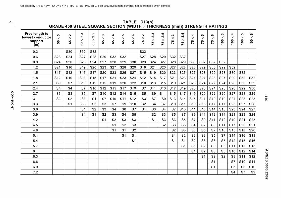
CO
PY
RIG
HT
41
9
AS
/NZ
S 3
00
0:2
00
7
TABLE D13(b) GRADE 450 STEEL SQUARE SECTION (WIDTH × THICKNESS (mm)) STRENGTH RATINGS
Free length to lowest conductor
support (m)
50
× 5
65
× 2
65
× 2
.3
65
× 2
.5
65
× 3
65
× 4
65
× 5
65
× 6
75
× 2
75
× 2
.3
75
× 2
.5
75
× 3
75
× 3
.5
75
× 4
75
× 5
75
× 6
10
0 ×
3
10
0 ×
4
10
0 ×
5
10
0 ×
6
0.3 S30 S32 S32 S32
0.6 S28 S24 S27 S28 S29 S32 S32 S27 S28 S29 S32 S32
0.9 S24 S20 S23 S24 S27 S28 S29 S30 S23 S24 S27 S28 S29 S30 S32 S32 S32
1.2 S21 S16 S19 S20 S23 S27 S28 S29 S19 S21 S23 S27 S28 S28 S29 S30 S29 S32
1.5 S17 S12 S15 S17 S20 S23 S25 S27 S15 S19 S20 S23 S25 S27 S28 S29 S28 S30 S32
1.8 S12 S10 S13 S15 S17 S21 S23 S24 S12 S15 S17 S21 S23 S24 S27 S28 S27 S29 S32 S32
2.1 S9 S7 S10 S12 S15 S19 S20 S22 S10 S13 S15 S19 S21 S23 S24 S27 S24 S28 S30 S32
2.4 S4 S4 S7 S10 S12 S15 S17 S19 S7 S11 S13 S17 S19 S20 S23 S24 S23 S28 S29 S30
2.7 S3 S3 S5 S7 S10 S12 S14 S15 S5 S9 S11 S15 S17 S19 S20 S22 S20 S27 S28 S29
3 S2 S2 S3 S4 S7 S10 S11 S12 S3 S7 S9 S13 S14 S15 S17 S19 S19 S24 S28 S28
3.3 S1 S3 S3 S3 S7 S9 S10 S2 S4 S7 S10 S11 S13 S15 S17 S17 S23 S27 S28
3.6 S1 S2 S3 S4 S6 S7 S1 S3 S4 S7 S10 S11 S13 S14 S15 S23 S24 S27
3.9 S1 S1 S2 S3 S4 S5 S2 S3 S5 S7 S9 S11 S12 S14 S21 S23 S24
4.2 S1 S2 S3 S3 S1 S3 S3 S5 S7 S9 S11 S12 S19 S21 S23
4.5 S1 S2 S3 S2 S3 S3 S4 S7 S9 S11 S17 S20 S21
4.8 S1 S1 S2 S2 S3 S3 S5 S7 S10 S15 S18 S20
5.1 S1 S1 S1 S2 S3 S3 S5 S7 S14 S16 S18
5.4 S1 S1 S1 S2 S3 S3 S5 S12 S15 S16
5.7 S1 S1 S2 S3 S3 S11 S13 S15
6 S1 S2 S3 S3 S10 S12 S14
6.3 S1 S2 S2 S8 S11 S12
6.6 S1 S7 S10 S11
6.9 S1 S5 S8 S10
7.2 S4 S7 S9
A1
Accessed by TAFE NSW - SYDNEY INSTITUTE - ULTIMO on 07 Feb 2013 (Document currency not guaranteed when printed)

AS/NZS 3000:2007 420
COPYRIGHT
APPENDIX E
ELECTRICAL INSTALLATION REQUIREMENTS IN NATIONAL BUILDING CODES
(Informative)
E1 SCOPE
This Standard (AS/NZS 3000) contains provisions relating to the protection of an electrical installation from fire and electric shock, which are dependent on, or incorporated in, building requirements. Thus, reference to National Building Codes is recommended for clarification of the application and any exceptions. National Building Codes also contain a number of other provisions which relate to the design, selection and installation of equipment that forms part of an electrical installation, and which are intended to satisfy objectives for health, amenity, sustainability and energy efficiency.
This Appendix outlines the above provisions in order to inform the electrical industry and practitioners who work with AS/NZS 3000 of measures affecting electrical installations implemented under the National Construction Code Series (NCC) for Australia and the New Zealand Building Code (NZBC).
E2 AUSTRALIA
E2.1 General
The NCC is written by the Australian Building Codes Board in conjunction with the building and plumbing authorities of the States and Territories. Its goals are nationally consistent health, safety, amenity and sustainability in building construction and plumbing and drainage.
The NCC is adopted under building and plumbing construction legislation in Australian States and Territories, which have responsibility for building construction and plumbing and drainage installations. Amended/revised annually, the NCC is implemented through building surveyors, both local government and private, and other professional practitioners.
The NCC is in three volumes: Volume 1—Building Code of Australia Class 2 to Class 9 Buildings; Volume 2—Building Code of Australia Class 1 and Class 10 Buildings (Houses and associated structures); and Volume 3—Plumbing Code of Australia (PCA) for plumbing and drainage associated with all classes of buildings.
The NCC is performance-based and contains fundamental ‘Performance Requirements’ together with acceptable solutions, known as ‘Deemed-to-Satisfy Provisions’, often based on compliance with standards.
A
A2
Acc
esse
d by
TA
FE
NS
W -
SY
DN
EY
INS
TIT
UT
E -
ULT
IMO
on
07 F
eb 2
013
(Doc
umen
t cur
renc
y no
t gua
rant
eed
whe
n pr
inte
d)

421 AS/NZS 3000:2007
COPYRIGHT
E2.2 Provisions in the NCC
E2.2.1 General
Volumes 1 and 2 of the NCC contain provisions that may affect the selection and installation of equipment that forms part of an electrical installation, and which may vary according to the building classification, construction, use and local environment. These provisions are subject to variations between States and Territories, but can be generally categorized as follows:
(a) Fire safety—these safety measures are also reflected in relevant clauses of AS/NZS 3000.
(b) Health, amenity sustainability and energy efficiency—these measures relate to the selection and installation of electrical equipment to meet objectives other than safety, including access for persons with disabilities, and reduced greenhouse gas emissions.
E2.2.2 Fire safety
Provisions in the NCC for fire safety include the following:
(a) Fire-resistance of building elements and fire hazard properties of materials.
(b) Penetrations for electrical services in fire-resistant walls, floors and ceilings, and protection by fire-stop seals and systems.
(c) Fire separation of substations and switchrooms for main switchboards supplying emergency equipment.
(d) Separation of switchgear and protection of wiring systems associated with circuits of emergency equipment.
(e) Limitation on electrical services installed in exits and associated paths of travel.
(f) Fire fighting equipment systems including fire hydrants, fire hose reels and sprinklers.
(g) Smoke hazard management systems including smoke exhaust.
(h) Smoke detection and alarm systems, fire control centres including fire indicator panels and building occupant warning systems.
(i) Lifts for emergency use or access for people with disabilities.
(j) Emergency escape lighting, exit and direction signs.
(k) Standby power system for fire and smoke control systems, and emergency escape lighting in buildings containing atriums.
(l) Thermal insulation requirements of the building fabric (depending on climate zone) that may affect the location of electrical equipment that produces heat, e.g. recessed downlights and bathroom heaters.
(m) Lighting in assembly buildings such as theatres, stages and public halls.
(n) Smoke alarms and escape lighting in residential premises.
A2
Acc
esse
d by
TA
FE
NS
W -
SY
DN
EY
INS
TIT
UT
E -
ULT
IMO
on
07 F
eb 2
013
(Doc
umen
t cur
renc
y no
t gua
rant
eed
whe
n pr
inte
d)

AS/NZS 3000:2007 422
COPYRIGHT
E2.2.3 Health and amenity
Provisions in the NCC for health and amenity include the following:
(a) Artificial lighting to enable safe movement.
(b) Lighting for refrigerated chambers, strong-rooms and vaults.
(c) Selection and location of socket-outlets and lighting to maintain sound insulation properties.
(d) Accessibility features, including hearing augmentation, signage and location of socket-outlets and switches.
E2.2.4 Sustainability and energy efficiency
Provisions in the NCC for sustainability and energy efficiency include the following:
(a) Electricity metering separated for lighting, power, airconditioning and other significant plant in commercial and other large buildings.
(b) Limitation on the energy consumption of interior and exterior artificial lighting including the use of automatic switching and dimming controls.
(c) Limitation on electric resistance water heating (including swimming and spa pools) and electric resistance space heating in residential premises.
(d) Controls to limit operation of swimming and spa pool pumps, airconditioning, ventilation or heating systems.
(e) Equipment provided to facilitate the efficient use of electricity for artificial heating and cooling, including ceiling fans to provide air movement, sealing devices to prevent the loss of conditioned air, and shading devices to limit unwanted heat gain.
(f) Thermal insulation measures to increase the level of insulation remaining where bulk insulation materials have been removed to provide for the safe operation of recessed equipment.
(g) Ongoing maintenance of ventilation, heating, cooling and hot water systems, including the ability to access systems, to ensure efficient performance.
E3 NEW ZEALAND
E3.1 General
The NZBC is the First Schedule to the New Zealand Building Regulations 1992. The NZBC is a performance-based code that contains provisions under the headings of—
(a) stability;
(b) fire safety;
(c) access;
(d) moisture;
(e) safety of users;
NZ
A2
Acc
esse
d by
TA
FE
NS
W -
SY
DN
EY
INS
TIT
UT
E -
ULT
IMO
on
07 F
eb 2
013
(Doc
umen
t cur
renc
y no
t gua
rant
eed
whe
n pr
inte
d)

423 AS/NZS 3000:2007
COPYRIGHT
(f) services and facilities; and
(g) energy efficiency.
NOTE: The NZBC was reviewed during 2007 to align with the requirements of the New Zealand Building Act 2004.
E3.2 Extent of electrical installations in the NZBC
The NZBC clauses that relate to electrical work, and are current and valid at the publication of this Standard, include the following:
(a) B1 Structure Penetrations in structural members must not compromise the integrity of the building.
(b) C2 Prevention of fire occurring Electrical installations must not cause a fire to start.
(c) Fire affecting areas beyond the fire source Fire separations must not be compromised by penetration by electrical wiring.
(d) D2 Mechanical installations for access Requirements for buildings that require lifts.
(e) F3 Hazardous substances for processes Requirements for electrical installations in hazardous areas not to cause fire or explosion.
(f) F6 Lighting for emergency (to be amended to ‘visibility in escape routes’) The requirements for provision of emergency lighting and other forms of luminance.
(g) F7 Warning systems Installations of fire, smoke and other alarm systems that activate in an emergency.
(h) G2 Laundering Provision of a socket-outlet for a washing machine.
(i) G3 Food preparation and prevention of contamination Provisions of electrical outlets for cooking and food storage.
(j) G4 Ventilation Electrical work associated with the installation and control of mechanical heating systems and ventilating systems.
(k) G5 Interior environment Installations of systems for electrical space heating.
(l) G8 Artificial lighting Electrical work associated with the installation of lighting.
(m) G9 Electricity Links to New Zealand Electricity Regulations 1997 and amendments and to AS/NZS 3000 for safe electrical installations.
(n) G12 Water supplies Electrical work associated with pumping of water.
(o) G13 Foul water Electrical work associated with the pumping of foul water.
(p) G14 Industrial liquid waste Electrical work associated with the control and pumping of trade waste.
A2
Acc
esse
d by
TA
FE
NS
W -
SY
DN
EY
INS
TIT
UT
E -
ULT
IMO
on
07 F
eb 2
013
(Doc
umen
t cur
renc
y no
t gua
rant
eed
whe
n pr
inte
d)

AS/NZS 3000:2007 424
COPYRIGHT
(q) H1 Energy efficiency Contains provisions for the efficient use of energy for—
(i) water heating;
(ii) lighting;
(iii) mechanical ventilation; and
(iv) heating and cooling.
E3.3 Building consents
Electrical work requires building consent if—
(a) it relates to a specified system of a building that is or will be covered by the building’s compliance schedule; or
(b) it is of a nature that would require a waiver or modification of the building code; or
(c) the building owner wishes to apply for a building consent for electrical work.
Certificates of Compliance, issued in accordance with the Electricity Regulations, have to be accepted by Building Consent Authorities as establishing compliance of the electrical work with the provisions of the Building Code.
NOTES:
1 Specified systems are listed in Schedule 1 of the Building Regulations 2005 (Specified Systems, Change the Use, and Earthquake-prone Buildings), and include emergency lighting, fire alarms, lifts, ventilation, and airconditioning systems.
2 A Certificate of Compliance for electrical work certifies compliance with the Electricity Regulations, but does not remove the requirement for electrical work to comply with non-electrical aspects of the Building Code.
A2
Acc
esse
d by
TA
FE
NS
W -
SY
DN
EY
INS
TIT
UT
E -
ULT
IMO
on
07 F
eb 2
013
(Doc
umen
t cur
renc
y no
t gua
rant
eed
whe
n pr
inte
d)

425 AS/NZS 3000:2007
COPYRIGHT
APPENDIX F
INSTALLATION OF SURGE PROTECTIVE DEVICES
(Informative)
F1 SURGE PROTECTIVE DEVICES (SPDs)
F1.1 General
This Appendix provides guidance on the installation of SPDs to provide limitation of transient overvoltages caused by power line disturbances and by natural events, such as lightning strikes to, or near to, exposed conductors, as discussed in Clause 2.7.3.
SPDs do not provide protection against prolonged overvoltage or power outages and brownouts.
One or more of the following conditions could warrant the installation of SPDs:
(a) Where lightning is prevalent.
(b) Where power disturbances are frequent, e.g. in industrial areas.
(c) Where the site is at the end of long overhead power lines.
(d) Where the site is exposed, e.g. on a hill.
(e) Where dwellings may be many hundreds or more metres apart, e.g. in outer suburban or rural areas.
(f) Where the dwelling contains sensitive electronic equipment, e.g. a home office, home theatre, computer network, etc.
AS/NZS 1768 provides a detailed risk assessment on the need for lightning and surge protection.
This Appendix does not take into account surge protective components that may be incorporated into appliances connected to the electrical installation. The presence of such components may modify the behaviour of the main SPD of the electrical installation and may need additional coordination.
F1.2 Selection and installation of SPDs
F1.2.1 Location
Primary SPDs are installed near the origin of the electrical installation or in the main switchboard.
Secondary SPDs are installed in switchboards remote from the main switchboard. Secondary SPDs should be coordinated with the primary SPDs in accordance with the manufacturer’s instructions.
Where premises contain sensitive electronic equipment, secondary protection in the form of plug-in surge filters may also be warranted.
Telecommunications, remote telemetry and industrial process control sites require special attention.
A2
Acc
esse
d by
TA
FE
NS
W -
SY
DN
EY
INS
TIT
UT
E -
ULT
IMO
on
07 F
eb 2
013
(Doc
umen
t cur
renc
y no
t gua
rant
eed
whe
n pr
inte
d)

AS/NZS 3000:2007 426
COPYRIGHT
F1.2.2 Installation
SPDs should be—
(a) installed after the main switch or isolation switch but prior to any RCD devices;
NOTE: Where the main switch is an RCD, refer to Paragraph F1.2.4.
(b) protected by an appropriate fuse or circuit breaker separate from the SPD;
(c) connected at the main switchboard from each phase to neutral;
NOTE: Figure F1.1 shows a typical connection of a primary SPD for a single-phase installation.
(d) connected at switchboards remote from the main switchboard and without MEN connection, from each phase to neutral and from neutral to earth;
NOTE: Figure F1.2 shows a typical connection of a secondary SPD for a single-phase installation. This is known as all mode protection as it includes active-earth protection and may be implemented using discrete components (as shown) or a composite device including a purpose designed neutral-earth component.
(e) legibly and permanently labelled as to their function, in accordance with Clause 2.9.5.1; and
(f) where alarmed to provide status indication, fail safe in operation.
AS/NZS 1768 provides further details on the selection of primary and secondary SPDs.
Neutra l bar
Load
Supply
Ear th bar
Ear thelectrode
Main switch
CB CB
SPD
MEN connection
RCD
FIGURE F1.1 PRIMARY SPD ON MAIN SWITCHBOARD
A2
Acc
esse
d by
TA
FE
NS
W -
SY
DN
EY
INS
TIT
UT
E -
ULT
IMO
on
07 F
eb 2
013
(Doc
umen
t cur
renc
y no
t gua
rant
eed
whe
n pr
inte
d)
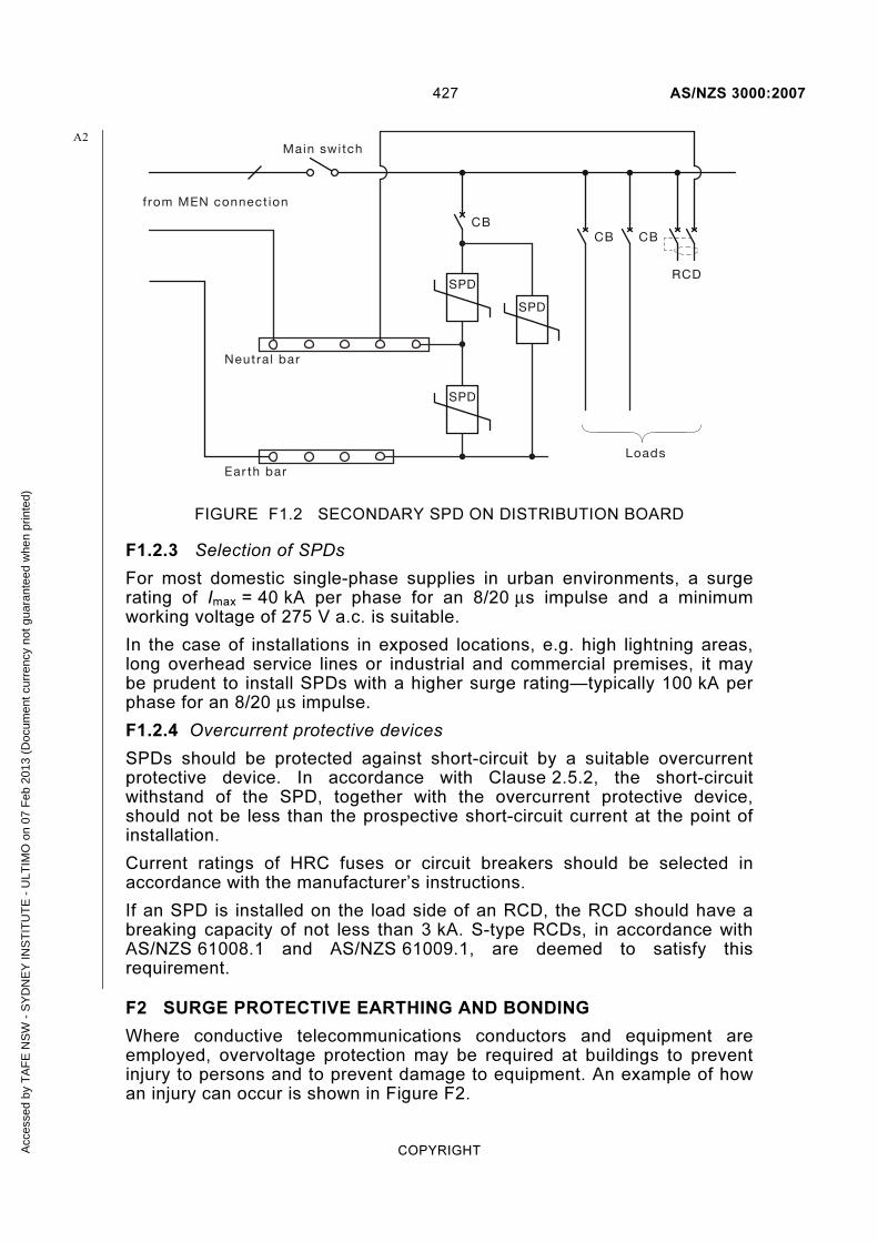
427 AS/NZS 3000:2007
COPYRIGHT
Neutra l bar
Loads
Ear th bar
Main switch
CBCB
SPD
CB
SPD
SPD
from MEN connect ion
RCD
FIGURE F1.2 SECONDARY SPD ON DISTRIBUTION BOARD
F1.2.3 Selection of SPDs
For most domestic single-phase supplies in urban environments, a surge rating of Imax = 40 kA per phase for an 8/20 μs impulse and a minimum working voltage of 275 V a.c. is suitable.
In the case of installations in exposed locations, e.g. high lightning areas, long overhead service lines or industrial and commercial premises, it may be prudent to install SPDs with a higher surge rating—typically 100 kA per phase for an 8/20 μs impulse.
F1.2.4 Overcurrent protective devices
SPDs should be protected against short-circuit by a suitable overcurrent protective device. In accordance with Clause 2.5.2, the short-circuit withstand of the SPD, together with the overcurrent protective device, should not be less than the prospective short-circuit current at the point of installation.
Current ratings of HRC fuses or circuit breakers should be selected in accordance with the manufacturer’s instructions.
If an SPD is installed on the load side of an RCD, the RCD should have a breaking capacity of not less than 3 kA. S-type RCDs, in accordance with AS/NZS 61008.1 and AS/NZS 61009.1, are deemed to satisfy this requirement.
F2 SURGE PROTECTIVE EARTHING AND BONDING
Where conductive telecommunications conductors and equipment are employed, overvoltage protection may be required at buildings to prevent injury to persons and to prevent damage to equipment. An example of how an injury can occur is shown in Figure F2.
A2
Acc
esse
d by
TA
FE
NS
W -
SY
DN
EY
INS
TIT
UT
E -
ULT
IMO
on
07 F
eb 2
013
(Doc
umen
t cur
renc
y no
t gua
rant
eed
whe
n pr
inte
d)

AS/NZS 3000:2007 428
COPYRIGHT
Electr icalSwitchboard
I
Distant ear th(zero volts)
VE
Telecommunicat ions serviceEar th e lectrode
V
FIGURE F2 EXAMPLE OF HOW A TRANSIENT OVERVOLTAGE DEVELOPS A HAZARDOUS VOLTAGE DIFFERENCE IN A BUILDING
A transient overvoltage on the distributor’s network may result in a high surge current to earth via the MEN connection in the electrical switchboard. This momentarily raises the local earth potential (VE)—typically by tens of thousands of volts. Thus, any object connected to the local earth, e.g. earthed electrical appliances, such as the refrigerator shown, metallic plumbing, concrete floor slab, etc., will momentarily be raised in potential.
To minimize the cost of installing overvoltage protection at domestic premises, all conductive services should enter the building as close as practicable to the main earth bar. To be effective the conductor from the telecommunications primary protection SPD to the main earth bar should be 1.5 m or less in length.
Bonding of metallic services, such as gas and water pipes, and conductive objects, e.g. concrete floors and metallic walls, etc. is recommended.
Primary protection for telecommunication lines is provided by a gas discharge tube (GDT). At domestic premises, this is preferably installed in a wall box near the electrical switchboard and connected to the main earth bar. Figure F3 shows this connection in the Protector Housing.
A special need exists for earthing of conductive telecommunications equipment. Current standards require a hard-wired earth for some equipment. There is a range of equipment and services that need to be bonded to the main earth bar, e.g. telecommunications SPDs and cable screens, antennas, CATV, fibre to the premises equipment, etc.
Some electrical installation practices make access to the earth electrode and earthing conductor difficult. To achieve the necessary short telecommunication bonding conductor, a bonding bar or terminal external to the main switchboard and mounted outside the meter box or electrical
Acc
esse
d by
TA
FE
NS
W -
SY
DN
EY
INS
TIT
UT
E -
ULT
IMO
on
07 F
eb 2
013
(Doc
umen
t cur
renc
y no
t gua
rant
eed
whe
n pr
inte
d)

429 AS/NZS 3000:2007
COPYRIGHT
switchboard on an outside wall is recommended for domestic installations. It will assist telecommunications carriers if the bonding bar or terminal is provided when the switchboard is installed.
This method is detailed in AS/ACIF S009 (Method 1) and is shown below in Figure F3.
housing
Electr ical switchboard Equipotentia l bond to MEBvia a bonding bar or terminal
Protector
1.5 metres preferred
Bondingconductor
Main ear thing conductor
Bonding bar or terminal(Communications Ear th Terminal - CET )
Ear th electrode
Equipotent ia lbonding point
Main ear thing bar or terminal
FIGURE F4 PREFERRED METHOD OF BONDING THE PRIMARY TELECOMMUNICATIONS PROTECTOR TO THE MAIN EARTH
Acc
esse
d by
TA
FE
NS
W -
SY
DN
EY
INS
TIT
UT
E -
ULT
IMO
on
07 F
eb 2
013
(Doc
umen
t cur
renc
y no
t gua
rant
eed
whe
n pr
inte
d)

AS/NZS 3000:2007 430
COPYRIGHT
APPENDIX G
DEGREES OF PROTECTION OF ENCLOSED EQUIPMENT
(Informative)
G1 INTRODUCTION
The degree of protection of an item of enclosed equipment is expressed as an IP (International Protection) rating, in accordance with AS 60529.
The ‘IP’ rating is usually written as ‘IP’ followed by two numbers and, sometimes, an additional letter.
The first number, from 1 to 6, designates a degree of ‘protection against solid objects’, and ‘protection of persons against access to hazardous parts’.
The second number, from 1 to 8, designates a degree of ‘protection against entry of water with harmful effects’.
If a specific degree of protection is not designated, an ‘X’ is used instead of either one or both numbers.
The additional letter, from A to D, when used, designates a degree of ‘protection of persons against access to hazardous parts’.
On infrequent occasions, a supplementary letter, H, M, S or W, is used to designate special classes of electrical equipment.
NOTES:
1 Figure G1 gives further information and Figure G2 gives an example to facilitate the understanding of the IP code covered by AS 60529.
2 See AS 60529 for test results.
Acc
esse
d by
TA
FE
NS
W -
SY
DN
EY
INS
TIT
UT
E -
ULT
IMO
on
07 F
eb 2
013
(Doc
umen
t cur
renc
y no
t gua
rant
eed
whe
n pr
inte
d)

431 AS/NZS 3000:2007
COPYRIGHT
G1a—First numeral—Protection against ingress of solid objects Protection of persons
against access to hazardous
parts with:
IP Requirements Example
0 No protection Non-protected
1
Full penetration of 50 mm diameter sphere not allowed. Contact with hazardous parts
not permitted
Back of hand
2
Full penetration of 12.5 mm diameter sphere not allowed. The jointed test finger shall
have adequate clearance from hazardous parts
Finger
3 The access probe of 2.5 mm diameter shall not penetrate
Tool
4 The access probe of 1.0 mm diameter shall not penetrate
Wire
5 Limited ingress of dust
permitted (no harmful deposit) Wire
6 Totally protected against
ingress of dust Wire
FIGURE G1 (in part) IP CODES
Acc
esse
d by
TA
FE
NS
W -
SY
DN
EY
INS
TIT
UT
E -
ULT
IMO
on
07 F
eb 2
013
(Doc
umen
t cur
renc
y no
t gua
rant
eed
whe
n pr
inte
d)

AS/NZS 3000:2007 432
COPYRIGHT
G1b—Second numeral—Protection against harmful ingress of water Protection from water IP Prescriptions Example
0 No protection Non-protected
1 Protected against vertically
falling drops of water. Limited ingress permitted
Vertically dripping
2
Protected against vertically falling drops of water with
enclosure tilted 15° from the vertical. Limited ingress
permitted
Dripping up to 15° from the
vertical
3 Protected against sprays to
60° from the vertical. Limited ingress permitted
Limited spraying
4 Protected against water
splashed from all directions. Limited ingress permitted
Splashing from all directions
5 Protected against jets of water.
Limited ingress permitted
Hosing jets from all
directions
6 Protected against strong jets of
water. Limited ingress permitted
Strong hosing jets from all directions
7 Protected against the effects of immersion between 15 cm and
1 m
Temporary immersion
8 Protected against long periods of immersion under pressure
Continuous immersion
FIGURE G1 (in part) IP CODES
Acc
esse
d by
TA
FE
NS
W -
SY
DN
EY
INS
TIT
UT
E -
ULT
IMO
on
07 F
eb 2
013
(Doc
umen
t cur
renc
y no
t gua
rant
eed
whe
n pr
inte
d)
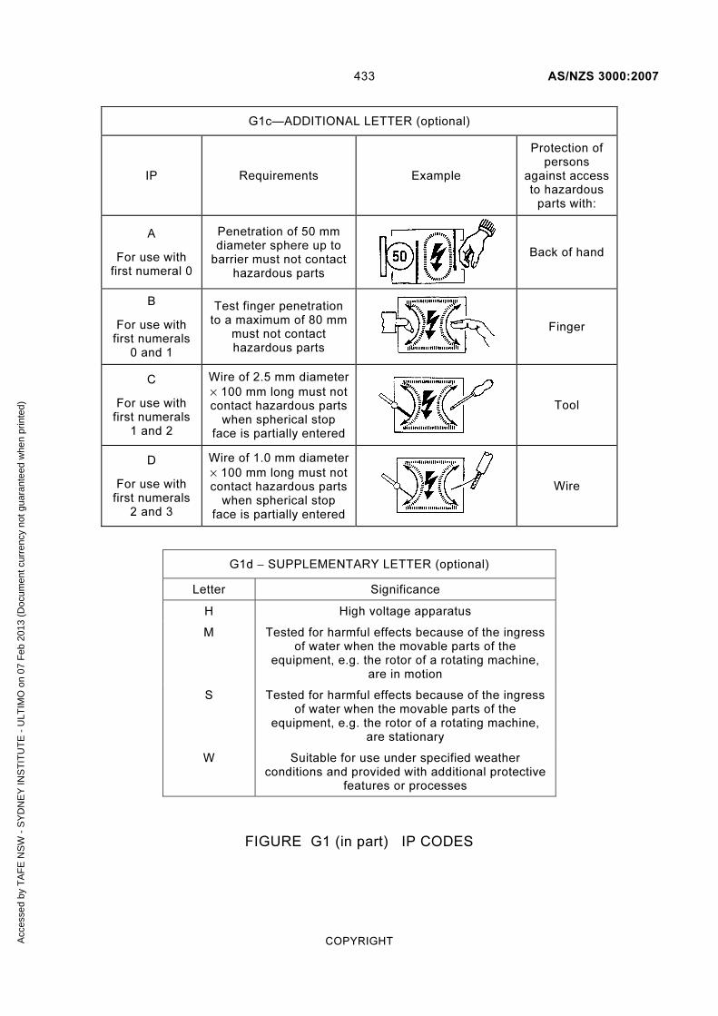
433 AS/NZS 3000:2007
COPYRIGHT
G1c—ADDITIONAL LETTER (optional)
IP Requirements Example
Protection of persons
against access to hazardous
parts with:
A
For use with first numeral 0
Penetration of 50 mm diameter sphere up to
barrier must not contact hazardous parts
Back of hand
B
For use with first numerals
0 and 1
Test finger penetration to a maximum of 80 mm
must not contact hazardous parts
Finger
C
For use with first numerals
1 and 2
Wire of 2.5 mm diameter
× 100 mm long must not contact hazardous parts
when spherical stop face is partially entered
Tool
D
For use with first numerals
2 and 3
Wire of 1.0 mm diameter
× 100 mm long must not contact hazardous parts
when spherical stop face is partially entered
Wire
G1d − SUPPLEMENTARY LETTER (optional)
Letter Significance
H High voltage apparatus
M Tested for harmful effects because of the ingress of water when the movable parts of the
equipment, e.g. the rotor of a rotating machine, are in motion
S Tested for harmful effects because of the ingress of water when the movable parts of the
equipment, e.g. the rotor of a rotating machine, are stationary
W Suitable for use under specified weather conditions and provided with additional protective
features or processes
FIGURE G1 (in part) IP CODES
Acc
esse
d by
TA
FE
NS
W -
SY
DN
EY
INS
TIT
UT
E -
ULT
IMO
on
07 F
eb 2
013
(Doc
umen
t cur
renc
y no
t gua
rant
eed
whe
n pr
inte
d)

AS/NZS 3000:2007 434
COPYRIGHT
Code let ters( internat iona l protect ion )
F i rst character ist ic numera l( numera ls 0 to 6, or let ter X )
Second character ist ic numera l( numera ls 0 to 8, or let ter X )
Addi t iona l let ter (opt iona l )( let ters A,B,C,D )
Addi t iona l let ter (opt iona l )( let ters H,M,S,W)
IP 2 3 C H
An enclosure with this designation (IP Code)
(2) – protects persons against access to hazardous parts with fingers; and
– protects the equipment inside the enclosure against ingress of solid foreign objects having a diameter of 12.5 mm and greater.
(3) – protects the equipment inside the enclosure against the harmful effects because of water sprayed against the enclosure.
(C) – protects persons handling tools having a diameter of 2.5 mm and greater and a length not exceeding 100 mm against access to hazardous parts (the tool may penetrate the enclosure up to its full length).
(H) – indicates that the equipment is high voltage apparatus.
FIGURE G.2 EXAMPLE OF ‘IP’ RATING
Acc
esse
d by
TA
FE
NS
W -
SY
DN
EY
INS
TIT
UT
E -
ULT
IMO
on
07 F
eb 2
013
(Doc
umen
t cur
renc
y no
t gua
rant
eed
whe
n pr
inte
d)

435 AS/NZS 3000:2007
COPYRIGHT
APPENDIX H
WS CLASSIFICATION OF WIRING SYSTEMS
(Informative)
H1 GENERAL
This Appendix provides guidance on the application of the WS classification of wiring systems, in accordance with AS/NZS 3013. This system classifies wiring systems according to their ability to—
(a) maintain circuit integrity under fire conditions for a specified period; and
(b) maintain circuit integrity against mechanical damage of specified severity.
NOTE: Elements of a wiring system may need replacement after exposure to a hazard.
This Appendix applies only to wiring systems that are in all other respects safe and suitable for their intended use and comply with relevant Standards.
The use of wiring systems tested in accordance with AS/NZS 3013 may not be necessary where elements of building construction provide satisfactory protection against the effects of fire and mechanical damage.
NOTE: The degree of protection against fire and mechanical damage required of a wiring system depends on the application. To determine specific requirements, reference should be made to Standards dealing with a particular application (see Paragraph H2).
H1.1 Designation
H1.1.1 General
The basic designation used to indicate the ability of a wiring system to maintain circuit integrity under fire conditions for a specified period and to maintain circuit integrity against mechanical damage of specified severity consists of a code of four characters.
H1.1.2 Basic designation
The designation consists of the following characters:
(a) The characteristic letters ‘WS’ (wiring system).
(b) Followed by a first characteristic numeral, where applicable (see Paragraph H1.2).
(c) Followed by a second characteristic numeral, where applicable (see Paragraph H1.3).
(d) A supplementary letter W, which may be added when required (see Paragraph H1.4).
Acc
esse
d by
TA
FE
NS
W -
SY
DN
EY
INS
TIT
UT
E -
ULT
IMO
on
07 F
eb 2
013
(Doc
umen
t cur
renc
y no
t gua
rant
eed
whe
n pr
inte
d)

AS/NZS 3000:2007 436
COPYRIGHT
H1.1.3 Single characteristic numeral designation
Where a class of protection is indicated by only one characteristic numeral, the letter X is used in the position normally occupied by the omitted characteristic numeral, e.g. WSX5 or WS2X.
H1.2 First characteristic numeral
The first characteristic numeral represents the time for which the wiring system is able to maintain circuit integrity under specified fire conditions.
Table H1 gives the minimum time the wiring system must maintain circuit integrity, when tested in accordance with AS/NZS 3013, in order to be assigned the associated characteristic numeral.
TABLE H1
DEGREE OF PROTECTION INDICATED BY THE FIRST CHARACTERISTIC NUMERAL
Degree of protection indicated by the first characteristic numeral
(Protection against exposure to fire)
First characteristic numeral
Minimum time for which the circuit integrity of the wiring system is
maintained (min)
X Degree of protection does not apply
1 15
2 30
3 60
4 90
5 120
H1.3 Second characteristic numeral
The second characteristic numeral represents the degree of mechanical impact and cutting load to which the wiring system can be subjected without losing circuit integrity.
Table H2 indicates the degree of impact for which the wiring system must maintain circuit integrity when tested in accordance with AS/NZS 3013.
Acc
esse
d by
TA
FE
NS
W -
SY
DN
EY
INS
TIT
UT
E -
ULT
IMO
on
07 F
eb 2
013
(Doc
umen
t cur
renc
y no
t gua
rant
eed
whe
n pr
inte
d)
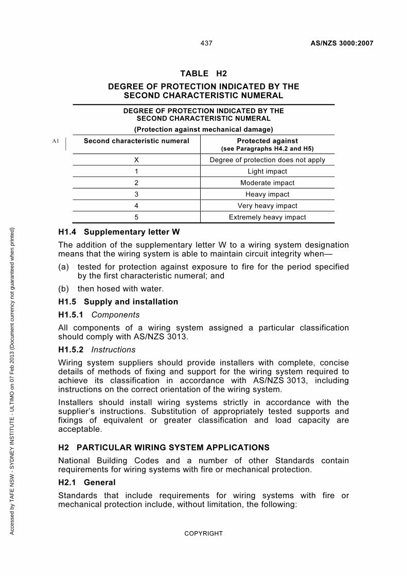
437 AS/NZS 3000:2007
COPYRIGHT
TABLE H2
DEGREE OF PROTECTION INDICATED BY THE SECOND CHARACTERISTIC NUMERAL
DEGREE OF PROTECTION INDICATED BY THE SECOND CHARACTERISTIC NUMERAL
(Protection against mechanical damage)
Second characteristic numeral Protected against (see Paragraphs H4.2 and H5)
X Degree of protection does not apply
1 Light impact
2 Moderate impact
3 Heavy impact
4 Very heavy impact
5 Extremely heavy impact
H1.4 Supplementary letter W
The addition of the supplementary letter W to a wiring system designation means that the wiring system is able to maintain circuit integrity when—
(a) tested for protection against exposure to fire for the period specified by the first characteristic numeral; and
(b) then hosed with water.
H1.5 Supply and installation
H1.5.1 Components
All components of a wiring system assigned a particular classification should comply with AS/NZS 3013.
H1.5.2 Instructions
Wiring system suppliers should provide installers with complete, concise details of methods of fixing and support for the wiring system required to achieve its classification in accordance with AS/NZS 3013, including instructions on the correct orientation of the wiring system.
Installers should install wiring systems strictly in accordance with the supplier’s instructions. Substitution of appropriately tested supports and fixings of equivalent or greater classification and load capacity are acceptable.
H2 PARTICULAR WIRING SYSTEM APPLICATIONS
National Building Codes and a number of other Standards contain requirements for wiring systems with fire or mechanical protection.
H2.1 General
Standards that include requirements for wiring systems with fire or mechanical protection include, without limitation, the following:
A1
Acc
esse
d by
TA
FE
NS
W -
SY
DN
EY
INS
TIT
UT
E -
ULT
IMO
on
07 F
eb 2
013
(Doc
umen
t cur
renc
y no
t gua
rant
eed
whe
n pr
inte
d)

AS/NZS 3000:2007 438
COPYRIGHT
AS 1670 Automatic fire detection and alarm systems—System design, installation, and commissioning
AS 2118 Automatic fire sprinkler systems (known as the SAA Code for Automatic Fire Sprinkler Systems)
AS 2220 Emergency warning and intercommunication systems in buildings
NZS 4512 Fire detection and alarm systems in buildings
H2.2 Pumpset systems
AS 2941 Fixed fire protection installations—Pumpset systems, requires that wiring systems associated with the operation of residential sprinkler pumpsets have a protection against exposure to fire of not less than 30 min,, i.e. WS2X.
Other pumpset systems are required to have a fire-rating of not less than 120 min, i.e. WS5X.
H2.3 Smoke-venting equipment
AS/NZS 1668 The use of ventilation and airconditioning in buildings
AS/NZS 1668.1 Part 1: Fire and smoke control in multi-compartment buildings, requires a rating of not less than WS52 for circuits supplying equipment required to operate in a smoke-venting mode.
H2.4 Lift circuits
AS 1735 Lifts, escalators and moving walks (known as the SAA Lift Code)
AS 1735.2 Part 2: Passenger and goods lifts—Electric, requires a rating of not less than WS52 for lift supply circuits required to have a fire-resistance rating.
H2.5 Central emergency lighting circuits
AS or AS/NZS 2293 series, Emergency escape lighting and exit signs in buildings.
AS 2293.1 Part 1: System design, installation and operation, requires a rating of not less than WS4X for submains and certain final subcircuits supplying central emergency lighting circuits in buildings required to be constructed of fire-resisting elements.
H2.6 Substation or main switchboard
The BCA requires conductors supplying a substation or main switchboard that supplies equipment required to operate in an emergency mode to be—
(a) classified WS53W if located in a position subject to damage by motor vehicles; or
(b) WS52W elsewhere; or
(c) otherwise be provided with a fire-resistance life of not less than two hours.
A2
Acc
esse
d by
TA
FE
NS
W -
SY
DN
EY
INS
TIT
UT
E -
ULT
IMO
on
07 F
eb 2
013
(Doc
umen
t cur
renc
y no
t gua
rant
eed
whe
n pr
inte
d)

439 AS/NZS 3000:2007
COPYRIGHT
H3 FIRE-PROTECTED WIRING SYSTEMS
A wiring system can be provided with protection against exposure to fire in the following two ways:
(a) The use of unenclosed or enclosed wiring systems classified in accordance with AS/NZS 3013 and not depending on fire-rated elements of building construction for thermal protection.
Where these wiring systems are used, they are routed via a pathway using fire-resisting building structural elements and supported and fixed, where necessary, by supports and fixings complying with the requirements of AS/NZS 3013.
(b) The use of fire-rated elements of building construction to provide thermal protection to wiring systems not complying with the requirements of AS/NZS 3013 for the degree of protection required.
H4 MECHANICALLY PROTECTED WIRING SYSTEMS
H4.1 General
Mechanical protection is provided to prevent accidental damage.
Accordingly, the approach should involve the provision of a protection system with the minimum number of protrusions that are likely to catch or cause damage to vehicles or injury to persons. At the same time, the mechanical protection system must provide adequate mechanical protection to prevent damage by contact with vehicles or persons.
In the installation of these systems, a primary consideration should be that, where possible, the wiring location should be chosen to restrict or to prevent the approach of any object likely to cause damage. Generally, this may be in protected corners or in some area away from the traffic that may cause the damage. Where such a location is not possible, further protection shall be provided.
Wiring systems can be—
(a) unenclosed (where the protection is an integral part of the cable or busway); or
(b) enclosed (where a protective cover is provided outside the wiring).
The impact and cutting energies for the various classification levels are specified in AS/NZS 3013.
Non-metallic materials may be expected to provide mechanical protection over a temperature range of −15 to +60°C. The manufacturer may certify extended or reduced ranges that should be externally marked on the protection system.
H4.2 Application of wiring systems
Wiring systems that maintain their circuit integrity under conditions of mechanical damage may be used as indicated below. The following examples are general indications only because the frequency and level of impact in any particular application is difficult to determine:
Acc
esse
d by
TA
FE
NS
W -
SY
DN
EY
INS
TIT
UT
E -
ULT
IMO
on
07 F
eb 2
013
(Doc
umen
t cur
renc
y no
t gua
rant
eed
whe
n pr
inte
d)

AS/NZS 3000:2007 440
COPYRIGHT
(a) WSX1 In internal domestic or office situations where some damage is considered likely.
(b) WSX2 In passageways in domestic, office and commercial locations where impact by hand trucks and barrows is considered likely.
(c) WSX3 In car parks and driveways where occasional impact of cars or light vehicles is possible.
(d) WSX4 In areas where impact by vehicles not exceeding two tonnes but with solid frames is likely.
(e) WSX5 In areas where impact by laden trucks exceeding two tonnes is likely.
NOTES:
1 Classified wiring systems are tested to withstand the above impact conditions. However, repeated impacts of these levels could lead to failure of the wiring system.
2 Impact energies for the higher classification are severe so that every effort should be made to avoid routing wiring through such areas.
H4.3 Unenclosed wiring systems
For unenclosed wiring systems, mechanically protected cables and busways complying with the requirements of AS/NZS 3013 should be selected. They should be routed via a pathway using impact-resistant building structural elements and supported, where necessary, by appropriate impact-resistant hardware and fixings. All components used in such wiring systems should be tested to be in accordance with the appropriate requirements of AS/NZS 3013.
H4.4 Enclosed wiring systems
The following recommendations apply to enclosed wiring systems:
(a) If mechanical protection of the wiring system is achieved by an additional enclosure, the protection may be in the form of—
(i) a complete enclosure, such as a conduit, pipe, trunking or other housing; or
(ii) a barrier that is interposed between the wiring system and the possible source of impact.
In both cases the protection must be capable of resisting the impact load.
(b) If cables are contained in conduit or piping, such enclosure should be type tested for the impact energy and ambient temperature range of the location in which it is installed.
(c) If cables are installed in a cable trunking, on a cable tray with covers, or in a similar manner, the enclosure should be type tested.
(d) Enclosed wiring systems for Classifications WSX1, WSX2 and WSX3 should be type-tested. While wiring systems for Classifications WSX4 and WSX5 can be type-tested, it is anticipated that these enclosures will be designed by a structural engineer.
Acc
esse
d by
TA
FE
NS
W -
SY
DN
EY
INS
TIT
UT
E -
ULT
IMO
on
07 F
eb 2
013
(Doc
umen
t cur
renc
y no
t gua
rant
eed
whe
n pr
inte
d)

441 AS/NZS 3000:2007
COPYRIGHT
H5 GUIDE TO MECHANICAL PROTECTION CLASSIFICATION
The following systems will generally provide the mechanical protection required for the classification under which they are listed.
H5.1 WSX1 mechanical protection systems
Provide light-duty protection against casual damage by pedestrians as follows:
(a) Wiring systems meeting requirements of the appropriate tests of AS/NZS 3013.
(b) One sheathed cable immediately adjacent to a projecting timber batten or similar corner so that the projection is not less than twice the dimension of the cable in that direction. See Figure H1.
(c) Cabling installed in light or medium-duty conduits complying with AS/NZS 2053.
(d) Small sheet-metal ducts with clip-on covers.
(e) PVC duct with clip-on covers.
D 2d( a ) Corner of masonr y wal l
D 2d( b ) T imber bat ten
d D d D
FIGURE H1 WSX1 PROTECTION BY LOCATION
H5.2 WSX2 mechanical protection systems
Provide protection against damage from hand-powered wheeled devices, e.g. hand trucks and wheelbarrows as follows:
(a) Wiring systems meeting requirements of the appropriate tests of AS/NZS 3013.
(b) Heavy-duty conduits complying with AS/NZS 2053.
(c) Armoured cables complying with AS/NZS 5000.1.
(d) Steel duct with a minimum metal thickness of not less than 1.6 mm, a screw fixed lid and unsupported width not exceeding 100 mm.
(e) Fabricated steel cover with metal not less than 1.6 mm thick, and un-reinforced unsupported width not exceeding 100 mm.
(f) Any WSX1 system with a 10 mm cover of plaster or concrete.
(g) MIMS cable complying with AS/NZS 60702.1.
Fixings used for WSX2 wiring systems are required to be capable of withstanding the specified mechanical tests.
Acc
esse
d by
TA
FE
NS
W -
SY
DN
EY
INS
TIT
UT
E -
ULT
IMO
on
07 F
eb 2
013
(Doc
umen
t cur
renc
y no
t gua
rant
eed
whe
n pr
inte
d)

AS/NZS 3000:2007 442
COPYRIGHT
H5.3 WSX3 mechanical protection systems
Provide medium-duty protection against damage from vehicles, such as cars and light commercial vehicles, as follows:
(a) Wiring systems meeting requirements of appropriate tests of AS/NZS 3013.
(b) Any wiring system with additional 2.0 mm sheet steel coverage with a maximum unsupported width of 100 mm.
(c) Any WSX2 systems with an additional 1.6 mm sheet steel coverage and unsupported width not exceeding 100 mm.
(d) Galvanized medium tube to AS 1074.
(e) Very heavy-duty conduits complying with AS/NZS 2053.
NOTE: Fixings of a type where a threaded metal screw or bolt engages a metal fastener solidly anchored to the building structure may be needed to satisfy a WSX3 classification.
Acc
esse
d by
TA
FE
NS
W -
SY
DN
EY
INS
TIT
UT
E -
ULT
IMO
on
07 F
eb 2
013
(Doc
umen
t cur
renc
y no
t gua
rant
eed
whe
n pr
inte
d)

443 AS/NZS 3000:2007
COPYRIGHT
APPENDIX I
PROTECTIVE DEVICE RATINGS AND METRIC EQUIVALENT SIZES FOR IMPERIAL CABLES USED IN ALTERATIONS ADDITIONS AND REPAIRS
(Informative)
I1 SCOPE
This Appendix provides guidance to the ratings of circuit-breakers and existing semi-enclosed rewireable fuses or plug-in circuit-breakers that may be used to provide protection against overload in accordance with Clause 2.5.3.2 where alterations, additions or repairs involve the use of existing conductors of an imperial size. It also provides metric equivalent cable sizes for situations where an alteration, addition or repair to an existing circuit involves the connection in parallel of conductors with metric dimensions with conductors of imperial dimensions.
I2 PROTECTIVE DEVICE RATINGS
The ratings provided in Table I1 may be used for electrical installations under the conditions shown.
NOTES:
1 The ratings are based on an ambient temperature of 40°C using a comparison of the cross-sectional area of the imperial conductor to the cross-sectional area of the nearest metric conductor.
2 In accordance with Clause 2.5.2, semi-enclosed rewireable fuses shall not be added for new work.
Acc
esse
d by
TA
FE
NS
W -
SY
DN
EY
INS
TIT
UT
E -
ULT
IMO
on
07 F
eb 2
013
(Doc
umen
t cur
renc
y no
t gua
rant
eed
whe
n pr
inte
d)

AS/NZS 3000:2007 444
COPYRIGHT
TABLE I1
PROTECTIVE DEVICE RATINGS
Two-core sheathed cable V 75 insulation (A)
V 60 insulation (A)
Size Installation method CB Fuse or plug-in CB *
CB Fuse or plug-in CB*
1/.044 Unenclosed 13 10 10 8
Partially surrounded 10 8 8 6
3/.029 Unenclosed 16 12 13 10
Partially surrounded 13 8 10 6
3/.036 Unenclosed 20 16 16 10
Partially surrounded 16 10 10 8
1/.064 Unenclosed 20 16 16 12
Partially surrounded 16 10 13 8
7/.029 Unenclosed 32 20 25 16
Partially surrounded 20 16 16 12
7/.036 Unenclosed 40 25 32 20
Partially surrounded 25 20 20 16
7/.044 Unenclosed 50 32 40 25
Partially surrounded 32 25 25 20
* Existing semi-enclosed rewireable fuse
I3 METRIC EQUIVALENT SIZES FOR IMPERIAL CONDUCTORS
Where an alteration, addition or repair to an existing circuit involves the connection in parallel of conductors with metric dimensions with existing conductors of imperial dimensions, Table I2 provides metric equivalent sizes.
NOTE: Clause 3.4.3 provides requirements for the connection of cables in parallel.
Acc
esse
d by
TA
FE
NS
W -
SY
DN
EY
INS
TIT
UT
E -
ULT
IMO
on
07 F
eb 2
013
(Doc
umen
t cur
renc
y no
t gua
rant
eed
whe
n pr
inte
d)

445 AS/NZS 3000:2007
COPYRIGHT
TABLE I2
SIZES OF IMPERIAL AND METRIC CABLES FOR CONNECTION IN PARALLEL
1 2 3
Imperial size Metric size
Number and diameter of wires
No/inch
Conductor size
in2
Conductor size
mm2
7/.036 0.0071 4
7/.044 0.0100 6
7/.052 0.0145 10
7/.064 0.0225 16
19/.044 0.0300 16
19/.052 0.0400 25
19/.064 0.0600 35
19/.072 0.0750 50
19/.083 0.1000 70
37/.064 0.1200 70
37/.072 0.1500 95
37/.083 0.2000 120
37/.093 0.2500 150
37/.103 0.3000 185
61/.093 0.4000 240
61/.103 0.5000 300
91/.093 0.6000 400
91/.103 0.7500 500
127/.093 0.8500 500
127/.103 1.0000 630
Acc
esse
d by
TA
FE
NS
W -
SY
DN
EY
INS
TIT
UT
E -
ULT
IMO
on
07 F
eb 2
013
(Doc
umen
t cur
renc
y no
t gua
rant
eed
whe
n pr
inte
d)

AS/NZS 3000:2007 446
COPYRIGHT
APPENDIX J
SYMBOLS USED IN THIS STANDARD
(Informative)
J1 INTRODUCTION
This Appendix provides guidance to the electrical symbols used in this Standard.
Table J1 provides a consolidated summary of all electrical symbols used, the meaning of the symbol and the reference to the standard symbol in AS 1102 series from which the symbol has been derived.
Acc
esse
d by
TA
FE
NS
W -
SY
DN
EY
INS
TIT
UT
E -
ULT
IMO
on
07 F
eb 2
013
(Doc
umen
t cur
renc
y no
t gua
rant
eed
whe
n pr
inte
d)
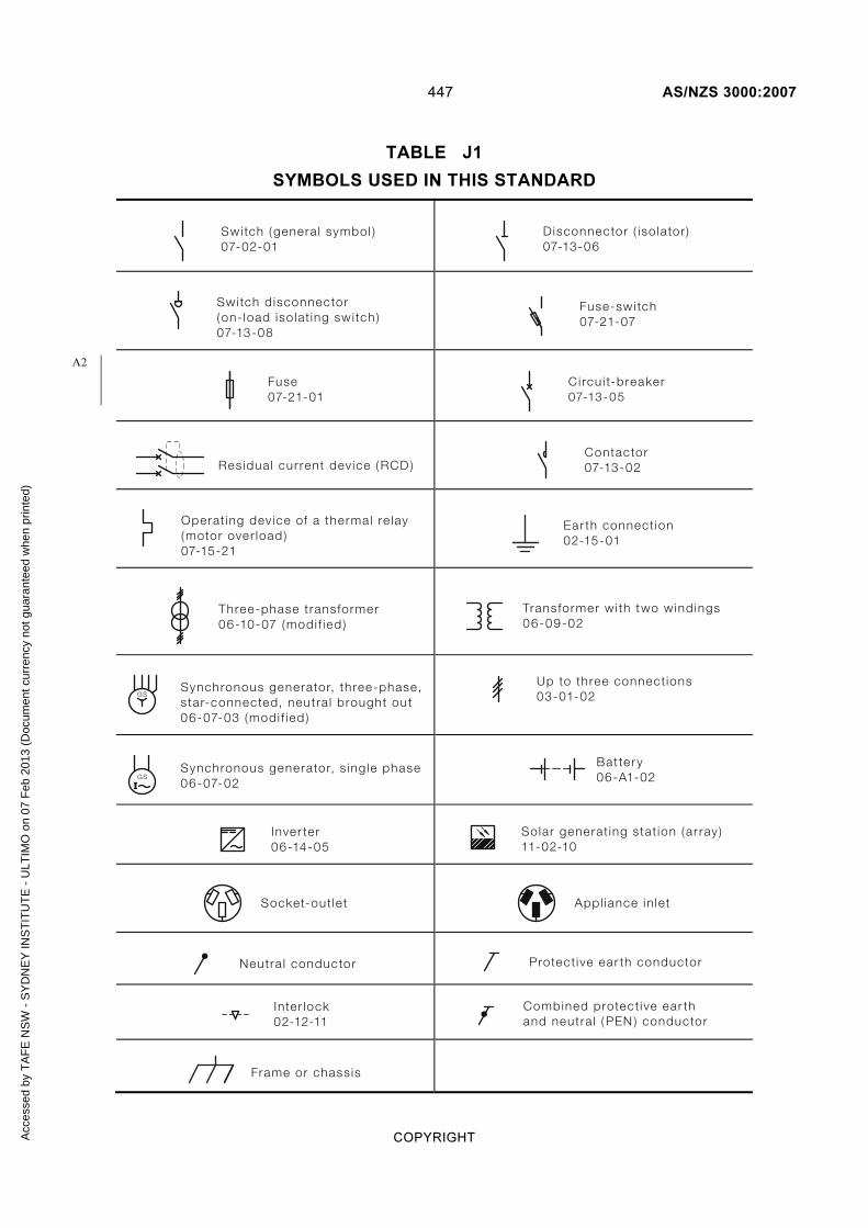
447 AS/NZS 3000:2007
COPYRIGHT
TABLE J1
SYMBOLS USED IN THIS STANDARD
Switch (genera l symbol )07-02-01
Disconnector ( iso lator )07-13-06
Switch d isconnector(on- load iso lat ing swi tch )07-13-08
Fuse-swi tch07-21-07
Fuse07-21-01
Circu i t-breaker07-13-05
Residual cur rent dev ice ( RCD )
Contactor07-13-02
Operat ing dev ice of a thermal re lay(motor over load )07-15-21
Ear th connect ion02-15-01
Three-phase transformer06-10-07 (modi f ied )
Transformer wi th two windings06-09-02
Synchronous generator, three-phase,star-connected, neutra l brought out06-07-03 (modi f ied )
GS
Up to three connect ions03-01-02
Synchronous generator, s ing le phase06-07-02
GSI
Bat ter y06-A1-02
Inver ter06-14-05
Solar generat ing stat ion (ar ray )11-02-10
Socket-out let
Appl iance in let
Neutra l conductor Protect ive ear th conductor
Inter lock02-12-11
Combined protect ive ear thand neutra l ( PEN ) conductor
Frame or chass is
A2
Acc
esse
d by
TA
FE
NS
W -
SY
DN
EY
INS
TIT
UT
E -
ULT
IMO
on
07 F
eb 2
013
(Doc
umen
t cur
renc
y no
t gua
rant
eed
whe
n pr
inte
d)

AS/NZS 3000:2007 448
COPYRIGHT
APPENDIX K
(deleted)
A1
Acc
esse
d by
TA
FE
NS
W -
SY
DN
EY
INS
TIT
UT
E -
ULT
IMO
on
07 F
eb 2
013
(Doc
umen
t cur
renc
y no
t gua
rant
eed
whe
n pr
inte
d)

449 AS/NZS 3000:2007
COPYRIGHT
APPENDIX L
ELECTRIC SHOCK SURVIVAL—Australia
EMERGENCY !—Electric shock may cause cardiac arrest.
DANGERS
Check for your own safety and the safety of the casualty and bystanders.
HIGH VOLTAGE—Wait until the power is turned off.
LOW VOLTAGE—Immediately switch off the power. If this is not practicable, pull or push the casualty clear of the electrical contact using material, such as wood, rope, clothing, plastic or rubber. Do not use metal or anything moist.
RESPONSIVENESS
Check for response (verbal and tactile stimuli), touch and talk.
SEND/Shout FOR HELP
Send a bystander to DIAL 000 Ambulance
If available send for Automatic External Defibrillator (AED)
If alone shout for help.
AIRWAY Place the casualty on his/her back.
Tilt the head back and raise the chin forward.
BREATHING Check for normal breathing, observe chest movement, listen and feel for breathing.
Give two initial breaths.
In the absence of normal breathing, if no one has gone for help, place casualty in recovery position and go for help.
CIRCULATION
Position hands on centre of the chest.
Give 30 chest compressions followed by 2 breaths. Depress breastbone 1/3 the chest depth (approx 4 cm or 5 cm) at the rate of 100 compressions a minute.
AA
Acc
esse
d by
TA
FE
NS
W -
SY
DN
EY
INS
TIT
UT
E -
ULT
IMO
on
07 F
eb 2
013
(Doc
umen
t cur
renc
y no
t gua
rant
eed
whe
n pr
inte
d)

AS/NZS 3000:2007 450
COPYRIGHT
As soon as available attach AED and follow its instructions.
Continue CPR, 30 compressions: 2 breaths.
When casualty’s normal breathing returns cease resuscitation and move the casualty into the recovery or coma position.
Keep a constant watch on the casualty, to ensure that they do not stop breathing again, until trained assistants take over.
This information is provided for guidance only. It is recommended that persons associated with the installation of electrical equipment or repair of electrical installations obtain Australian Resuscitation Council approved training in current resuscitation methods.
Acc
esse
d by
TA
FE
NS
W -
SY
DN
EY
INS
TIT
UT
E -
ULT
IMO
on
07 F
eb 2
013
(Doc
umen
t cur
renc
y no
t gua
rant
eed
whe
n pr
inte
d)

451 AS/NZS 3000:2007
COPYRIGHT
APPENDIX M
ELECTRIC SHOCK SURVIVAL—New Zealand
EMERGENCY !—Electric shock may cause cardiac arrest.
DANGERS
Check for your own safety and the safety of the casualty and bystanders.
HIGH VOLTAGE—Wait until the power is turned off.
LOW VOLTAGE—Immediately switch off the power. If this is not practicable, pull or push the casualty clear of the electrical contact using material, such as wood, rope, clothing, plastic or rubber. Do not use metal or anything moist.
RESPONSIVENESS
Check for response, gently shake and loudly shout.
SEND/Shout FOR HELP
Send a bystander to DIAL 111 Ambulance
If available send for Automatic External Defibrillator (AED)
If alone shout for help.
AIRWAY Place the casualty on his/her back.
Tilt the head back and raise the chin forward.
BREATHING Check for normal breathing, observe chest movement, listen and feel for breathing.
In the absence of normal breathing, if no one has gone for help, place casualty in recovery position and go for help.
CIRCULATION
Position hands on centre of the chest.
Give 30 chest compressions followed by 2 breaths. Depress breastbone 1/3 the chest depth (approx 4 cm or 5 cm) at the rate of 100 compressions a minute.
As soon as available attach AED and follow its instructions.
NZ
Acc
esse
d by
TA
FE
NS
W -
SY
DN
EY
INS
TIT
UT
E -
ULT
IMO
on
07 F
eb 2
013
(Doc
umen
t cur
renc
y no
t gua
rant
eed
whe
n pr
inte
d)

AS/NZS 3000:2007 452
COPYRIGHT
Continue CPR, 30 compressions: 2 breaths.
When casualty’s normal breathing returns cease resuscitation and move the casualty into the recovery or coma position.
Keep a constant watch on the casualty to ensure that they do not stop breathing again, until trained assistants take over.
This information is provided for guidance only. It is recommended that persons associated with the installation of electrical equipment or repair of electrical installations obtain New Zealand Resuscitation Council approved training in current resuscitation methods.
Acc
esse
d by
TA
FE
NS
W -
SY
DN
EY
INS
TIT
UT
E -
ULT
IMO
on
07 F
eb 2
013
(Doc
umen
t cur
renc
y no
t gua
rant
eed
whe
n pr
inte
d)

453 AS/NZS 3000:2007
COPYRIGHT
INDEX
The references in this index are to paragraph numbers.
A
accessibility
definition of 1.4.2
of socket-outlets 4.4.2.1
of switchboards 2.9.2.2
accessories
connection of 4.3.1–4.3.5
damage to 4.1.3
definition of 1.4.3
fire hazards 4.2.2
for lighting 4.5
in refrigeration rooms 6.6.4.3
in wet areas 6.2.4.3, 6.3.4.4, 6.4.4.4, 6.5.4.4
installation of 4.1.2
interference from 4.1.4
isolating switches for 2.3.4.5
protection
against burns 4.2.3
against thermal effects 4.2.1
selection of 4.1.2
wiring of 4.3.5
acoustic insulation 4.2.2.6, 4.4.2.2
aerial conductor line, forces on D1, D4
aerial conductors See conductors: aerial
aerial wiring systems See wiring systems: aerial
agricultural
premises See sanitization areas
shows 7.8.2.5
air-handling systems 4.13.1.1, 7.2.1.2
alternating current systems, isolating 2.3.2.1.1
aluminium conductors 3.5.1, 3.7.2.1.2, 5.3.2.1.2
appliances
connection of 4.3.1–4.3.5
cooking 4.7.1–4.7.2, C2.5.3
damage to 4.1.3
definition of 1.4.6
fire hazards 4.2.2
fixed 1.4.7
hand-held 1.4.8
hot water 4.8.1–4.8.2.3
in refrigeration rooms 6.6.4.5
in wet areas 6.3.4.5, 6.4.4.5
installation of 4.1.2
interference from 4.1.4
isolating switches for 2.3.4.5
portable 1.4.9
protection
against burns 4.2.3
against thermal effects 4.2.1
stationary 1.4.10
steam 4.8.1–4.8.2.3
wiring of 4.3.5
arc welding machines C2.5.2.2
arcing fault currents 2.5.5.1–2.5.5.3, 2.9.2.2,
7.2.2.2
arcs, protection from 4.2.2.4
armoured cables 1.4.18, 3.2, 3.9.6, 3.9.10.2
auto reclose devices 2.4.4
automatic disconnection 1.5.5.3, 1.5.9, 2.1.2,
2.4.2, 2.5.5.3, 2.7.2, 5.1, 5.2.1, 5.7, 8.3.3,
8.3.9, B4
autotransformers 4.14.4 See also transformers
B
barriers 1.4.16, 1.5.4.4, 2.5.5.2, 3.9.8.2–3.9.8.3
fire-resistant 3.9.9.3
bars, terminal 2.9.3.3, 2.9.4.1–2.9.4.3, 5.3.1,
5.3.5.1
basic insulation 1.4.60
basic principles, of wiring 1.5–1.5.14
baths and showers 5.6.2.5
installing equipment near 6.2.4
luminaires near 6.2.4.4
prohibited protection measures 6.2.3
protection against shock 6.2.3
selecting equipment for 6.2.4
socket-outlets near 6.2.4.2
switchboards near 6.2.4.6
switches near 6.2.4.3
zones 6.2.2.1
See also damp situations
batteries 2.5.4.4, 7.3.1, 7.5.3, 7.5.9.2
in electricity converters 4.12.4.2
in electricity generation systems 7.3.4.2
selection and installation 4.17
BCA See Building Code of Australia
boats 7.8.2.4
bonding conductors 3.8.1, 3.10.1.1, 5.6.3,
7.4.7.4, 8.3.5
See also equipotential bonding
braided conductors 5.3.2.1.1
Building Code of Australia E2
energy efficiency provisions E2.3
building consents E3.3
building materials, earthing of 5.4.1.2, 5.4.6
bundled cables 3.12.1
burns, protection against 1.5.1, 4.2.3
busbar trunking system See busways
busways 3.9.7.1.2, 3.15, 5.3.2.2, H4.3
current-carrying capacity 3.4.1
Acc
esse
d by
TA
FE
NS
W -
SY
DN
EY
INS
TIT
UT
E -
ULT
IMO
on
07 F
eb 2
013
(Doc
umen
t cur
renc
y no
t gua
rant
eed
whe
n pr
inte
d)

AS/NZS 3000:2007 454
COPYRIGHT
C
cables
armoured 1.4.18, 3.2, 3.9.6, 3.9.10.2
bundled 3.12.1
catenary See catenary
colour restrictions 1.7.2
connecting 3.7
core 1.4.19
defined 1.4.17
electromagnetic interference 3.9.10.2
See also interference
enclosure of 3.7.3, 3.10.1–3.10.3.9, C6
See also enclosures
European 3.8.3.3
flexible 1.4.20, 3.9.7.4
heating 4.10.2
identifying 4.10.6
protecting 4.10.5
in conduits, number of C6
in separated circuits 7.4.3
insulated 3.2, 3.4.2, 3.9.7.1.2–3.9.7.2,
3.12.1
joints in 3.7.3
limiting temperatures for 3.4.2
MIMS 1.4.21, 3.2, 3.9.7.3, 3.16
neutral-screened 1.4.22, 3.7.2.9.2, 3.12.1
parallel-webbed 3.7.2.9.2, 3.12.1
polymeric 3.4.2, 3.12.1, 7.4.7
screened 3.2
selecting protective devices for C3
sheathed 1.4.23, 3.2, 3.9.7.2
stranded 3.13.1
trunking 1.4.97, 3.10.3.9
twisted 3.12.1
types of 3.2
unarmoured 3.9.7.2
underground
extra-low voltage 7.5.11.3
See also underground wiring
unsheathed 3.9.7.1.2
with earthing conductors 5.3.3.4
with non-ferrous metal sheathing 3.9.10.3
XLPE 3.9.7.1.2
See also conductors, wiring, wiring systems
capacitors
connected in parallel 4.15.3.2–4.15.3.3
control of 4.15.3
discharge of 4.15.3
installation of 4.15.1–4.15.3.3
oil-filled 4.16.1
carnivals 7.8.2.5
carpet, wiring beneath 3.9.7.6
catenary
clearances for 3.13.3
earthing of 5.3.2.3
supports for 3.13.2
wiring of 1.4.99, 3.2, 3.13
cathodic protection systems 5.2.2, 5.8
ceilings, suspended 1.4.24, 3.9.3.2, 4.5.2.4
CFS units 2.5.2
changeover switches 7.2.2.3, 7.3.8.1.2
circuit protection guide B1–B5.2.3
circuit-breakers 1.4.26, 2.2.1.2, 2.3.2.1.1,
2.3.2.2.1, 2.3.5.2, 2.4.3, 2.5.2, 2.5.7.2.3, 2.8.2,
3.4.4, 7.2.9.2, 7.4.6, B3.2.2.2
in switchboards 2.9.3.4
miniature 5.7.4
rating of 4.15.2.2, I1
with surge protection devices F1.2.4
circuits 2.2.1
arrangement of B2, C1–C6.2
control 2.3.7.4
definition of 1.4.25
design of 1.6.5
division of 2.2.1
for safety devices 2.2.1
heavy current 2.5.5.1
isolation of 2.3.2.1
See also isolation, isolating
switches
maximum length of B5
calculating B5.2
multiphase 2.2.1.2, 3.5.2
protecting B1–B5
See also protection
required number of C5.1
separated See electrical separation
single-phase 2.2.1.2, 3.5.2
testing 8.3.8
See also testing
circulating currents 3.9.10, 4.12.5–4.12.5.1,
7.3.5–7.3.6
class 1 equipment 1.4.27
class 2 equipment 1.4.28
protection by 1.5.5.4
class 3 equipment 1.4.29
clearances
for aerial wiring systems 3.12.3, 7.5.11.2
for catenary cabling 3.13.3
for conductors in switchboards 2.9.3.3
for recessed luminaires 4.5.2.3
cold-cathode illumination systems 7.8.2.6
combustible dusts See hazardous areas
compliance 1.9.4.5
See also inspections, testing, verification
compression joints 3.7.2.3.2
conductive part
exposed 1.4.53, 1.5.5, 2.4.2, 5.1.2, 5.2.1
extraneous 1.4.54, 1.5.5.3, 5.1.2, 5.4.1.1,
5.6.1, 5.6.2.6, 5.7.5, 6.3.3.2, 7.4.6, 7.5.5
conductors
active 1.4.4, 2.3.2.1.1
aerial 1.4.5, 3.5.1, 3.7.2.9.1, 3.9.7.1.2,
3.12.1
earthing 3.8.3.4, 5.3.3.3, 5.5.5.4
for extra-low voltage installations
7.5.11.2
minimum size 3.12.2.2
supports for 5.4.5
aluminium 3.5.1, 3.7.2.1.2, 3.12.2.2
Acc
esse
d by
TA
FE
NS
W -
SY
DN
EY
INS
TIT
UT
E -
ULT
IMO
on
07 F
eb 2
013
(Doc
umen
t cur
renc
y no
t gua
rant
eed
whe
n pr
inte
d)
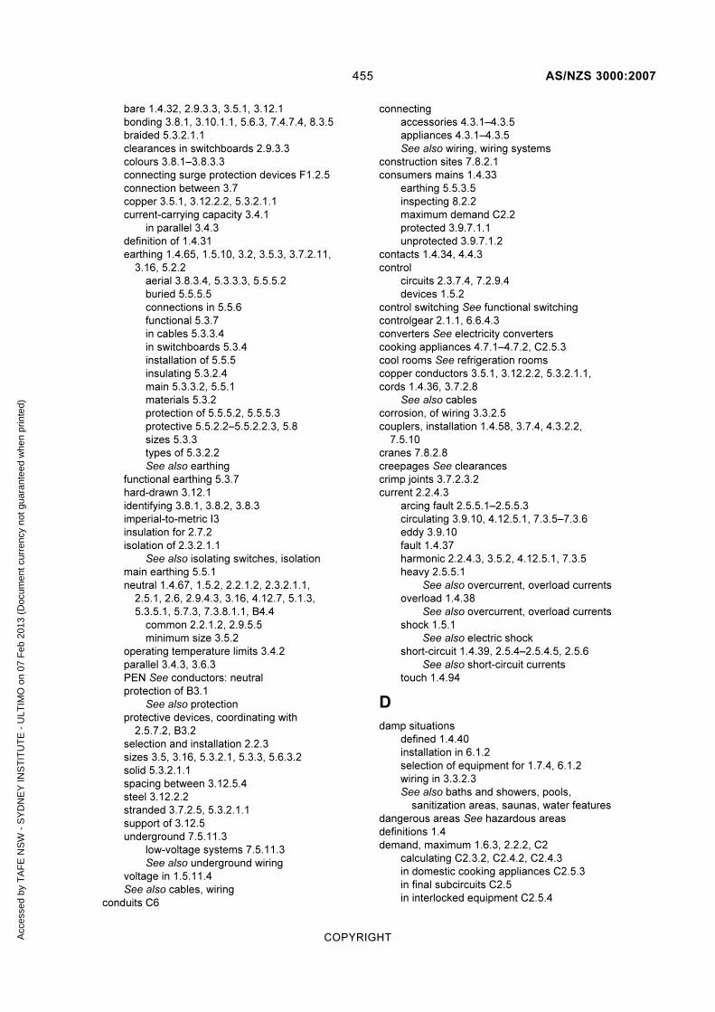
455 AS/NZS 3000:2007
COPYRIGHT
bare 1.4.32, 2.9.3.3, 3.5.1, 3.12.1
bonding 3.8.1, 3.10.1.1, 5.6.3, 7.4.7.4, 8.3.5
braided 5.3.2.1.1
clearances in switchboards 2.9.3.3
colours 3.8.1–3.8.3.3
connecting surge protection devices F1.2.5
connection between 3.7
copper 3.5.1, 3.12.2.2, 5.3.2.1.1
current-carrying capacity 3.4.1
in parallel 3.4.3
definition of 1.4.31
earthing 1.4.65, 1.5.10, 3.2, 3.5.3, 3.7.2.11,
3.16, 5.2.2
aerial 3.8.3.4, 5.3.3.3, 5.5.5.2
buried 5.5.5.5
connections in 5.5.6
functional 5.3.7
in cables 5.3.3.4
in switchboards 5.3.4
installation of 5.5.5
insulating 5.3.2.4
main 5.3.3.2, 5.5.1
materials 5.3.2
protection of 5.5.5.2, 5.5.5.3
protective 5.5.2.2–5.5.2.2.3, 5.8
sizes 5.3.3
types of 5.3.2.2
See also earthing
functional earthing 5.3.7
hard-drawn 3.12.1
identifying 3.8.1, 3.8.2, 3.8.3
imperial-to-metric I3
insulation for 2.7.2
isolation of 2.3.2.1.1
See also isolating switches, isolation
main earthing 5.5.1
neutral 1.4.67, 1.5.2, 2.2.1.2, 2.3.2.1.1,
2.5.1, 2.6, 2.9.4.3, 3.16, 4.12.7, 5.1.3,
5.3.5.1, 5.7.3, 7.3.8.1.1, B4.4
common 2.2.1.2, 2.9.5.5
minimum size 3.5.2
operating temperature limits 3.4.2
parallel 3.4.3, 3.6.3
PEN See conductors: neutral
protection of B3.1
See also protection
protective devices, coordinating with
2.5.7.2, B3.2
selection and installation 2.2.3
sizes 3.5, 3.16, 5.3.2.1, 5.3.3, 5.6.3.2
solid 5.3.2.1.1
spacing between 3.12.5.4
steel 3.12.2.2
stranded 3.7.2.5, 5.3.2.1.1
support of 3.12.5
underground 7.5.11.3
low-voltage systems 7.5.11.3
See also underground wiring
voltage in 1.5.11.4
See also cables, wiring
conduits C6
connecting
accessories 4.3.1–4.3.5
appliances 4.3.1–4.3.5
See also wiring, wiring systems
construction sites 7.8.2.1
consumers mains 1.4.33
earthing 5.5.3.5
inspecting 8.2.2
maximum demand C2.2
protected 3.9.7.1.1
unprotected 3.9.7.1.2
contacts 1.4.34, 4.4.3
control
circuits 2.3.7.4, 7.2.9.4
devices 1.5.2
control switching See functional switching
controlgear 2.1.1, 6.6.4.3
converters See electricity converters
cooking appliances 4.7.1–4.7.2, C2.5.3
cool rooms See refrigeration rooms
copper conductors 3.5.1, 3.12.2.2, 5.3.2.1.1,
cords 1.4.36, 3.7.2.8
See also cables
corrosion, of wiring 3.3.2.5
couplers, installation 1.4.58, 3.7.4, 4.3.2.2,
7.5.10
cranes 7.8.2.8
creepages See clearances
crimp joints 3.7.2.3.2
current 2.2.4.3
arcing fault 2.5.5.1–2.5.5.3
circulating 3.9.10, 4.12.5.1, 7.3.5–7.3.6
eddy 3.9.10
fault 1.4.37
harmonic 2.2.4.3, 3.5.2, 4.12.5.1, 7.3.5
heavy 2.5.5.1
See also overcurrent, overload currents
overload 1.4.38
See also overcurrent, overload currents
shock 1.5.1
See also electric shock
short-circuit 1.4.39, 2.5.4–2.5.4.5, 2.5.6
See also short-circuit currents
touch 1.4.94
D
damp situations
defined 1.4.40
installation in 6.1.2
selection of equipment for 1.7.4, 6.1.2
wiring in 3.3.2.3
See also baths and showers, pools,
sanitization areas, saunas, water features
dangerous areas See hazardous areas
definitions 1.4
demand, maximum 1.6.3, 2.2.2, C2
calculating C2.3.2, C2.4.2, C2.4.3
in domestic cooking appliances C2.5.3
in final subcircuits C2.5
in interlocked equipment C2.5.4
Acc
esse
d by
TA
FE
NS
W -
SY
DN
EY
INS
TIT
UT
E -
ULT
IMO
on
07 F
eb 2
013
(Doc
umen
t cur
renc
y no
t gua
rant
eed
whe
n pr
inte
d)

AS/NZS 3000:2007 456
COPYRIGHT
in welding machines C2.5.2
demolition sites 7.8.2.1
depth
of poles and posts D2
of underground wiring 3.11.4.4
design
documentation of 1.9.4.3
of electrical installation, general principles
1.6.1–1.6.5
detectors
fire 4.6, 7.2.1.2, H2
smoke 4.6, 7.2.1.2
See also safety services
dialysis installations, in the home 2.6.3.3
dielectrics, liquid 4.16
direct contact 1.4.34
protection against 1.5.4
See also electric shock
direct current systems, isolating 2.3.2.1.2
disconnection
automatic 1.5.5.3, 1.5.9, 2.5.5.3, 2.7.2, 5.1,
5.2.1, 5.7, 8.3.3, 8.3.9, B4
time 1.5.5.3, 5.7.2, B4.3
See also isolation, shutting down
distribution board 1.4.41
domestic cooking appliances 4.7, C2.5.3
See also cooking appliances
domestic installations
maximum demand C2.3
calculating C2.3.2
door seals, in refrigeration rooms 6.6.4.6
double insulation 1.4.60
duct heaters 4.11
See also heaters
ducts 1.4.42
dust, combustible See hazardous areas
E
earth electrodes 5.3.6
connecting main earthing conductor 5.5.1.2
installation of 5.3.6.3
location of 5.3.6.4
types of 5.3.6.2
earth fault-loop 5.7.3, B4.4
See also impedance: earth fault loop
earth sheath return systems See ESR systems
earthed situation, definition of 1.4.44
earthed, definition of 1.4.43
earthing
arrangements 5.1, 5.8
at switchboards 5.3.4
building materials 5.4.1.2, 5.4.6
catenary wiring 5.3.2.3
conductors 1.4.65, 1.5.10, 2.3.2.1.1, 3.2,
3.7.2.11, 3.16, 5.2.2
aerial 3.8.3.4, 5.3.3.3, 5.5.5.4
buried 5.5.5.5
connections between 5.5.6
in cables 5.3.3.4
installation of 5.5.5
insulating 5.3.2.4
main 5.3.3.2, 5.5.1
materials 5.3.2
protection of 5.5.5.2, 5.5.5.3
size of 3.5.3, 5.3.3
types of 5.3.2.2
consumers mains 5.5.3.5
contacts 4.4.3
continuity of 5.5.4
earth electrodes 5.5.1.2
electrical equipment 5.5.3.3
electricity converters 4.12.6
electricity generation systems 7.3.6
function of 5.2
functional 1.4.56, 5.2.2, 5.3.7
functional and protective 5.2.3
inspecting 8.2.2
lighting equipment 5.4.3
luminaires 5.4.4
main conductor 5.3.3.2, 5.5.1
MEN system 1.4.66, 5.1.3
methods of 5.5.3
of equipment 5.4
outbuildings 5.5.3.1
prohibited media 5.3.2.2
protective conductors 1.4.79, 5.2.1, 5.5.2.1–
5.5.2.2.3
socket-outlets 5.4.2
switchboards 5.5.3.4
systems
continuity of 8.3.5
earth electrodes 5.3.6
impedance of See impedance: earth
fault loop
parts of 5.3
telecommunications systems 5.6.2.7, F2
wiring systems 5.5.3.2
See also earth electrodes
eddy currents 3.9.10
edison screw lampholders 4.5.1.2
elastomeric insulation 3.4.2
electric
duct heaters 4.11
fences 7.8.4.3
heating systems 4.10.1–4.10.6
electric shock
first aid for L, M
protection against 1.5.3
See also direct contact, indirect contact
electrical equipment, in general
earthing 5.5.3.3
inspecting 8.2.2
See also accessories, appliances
electrical installation, in general
compliance 1.9.4.5
control of 2.3
design of 1.6.1–1.6.5
equipment for 1.7.4
in an outbuilding 2.3.4.1
verification of 1.8
electrical separation
Acc
esse
d by
TA
FE
NS
W -
SY
DN
EY
INS
TIT
UT
E -
ULT
IMO
on
07 F
eb 2
013
(Doc
umen
t cur
renc
y no
t gua
rant
eed
whe
n pr
inte
d)

457 AS/NZS 3000:2007
COPYRIGHT
by barriers 3.9.8.2–3.9.8.3
circuit requirements 7.4.3
protection by 1.5.5.5, 2.7.2, 5.8, 7.4
sources of supply 7.4.2
switching devices 7.4.4
testing of 7.4.7
electricity converters 4.12.1–4.12.8
control of 4.12.3
earthing 4.12.6
installation of 4.12.2
isolation of 4.12.4
overcurrent protection 4.12.5
with batteries 4.12.4.2
See also electricity generation systems
electricity generation systems 7.3
connected equipment
requirements of 7.3.7
connecting to 7.3.8.1.1
control of 7.3.3
installation of 7.3.2
isolation of 7.3.4
overcurrent protection 7.3.5
selection of 7.3.2
stand-alone 7.3.8.3
switching arrangements 7.3.8.1.2
See also electricity converters
electromagnetic interference 3.9.10.2, 3.9.11
effect on voltage 1.5.11.3
See also interference
electromedical treatment areas 7.8.2.2
elevators See lifts
emergency equipment See safety services
emergency escape lighting H2.5
emergency response, to electric shock L, M
emergency services See safety services
emergency systems See safety services
emergency switching 2.3.5.1
devices for 2.3.5.2
identifying 2.3.5.4
installation of 2.3.5.3
enclosed equipment, protection of G1
enclosures 1.5.4.4
definition 1.4.51
ferromagnetic 3.9.10.2
for cabling 3.7.3, 3.10.1–3.10.3.9
for joints or connections 3.7.3
installation of 3.10.3
type of 3.10.2
energisation, recording date of initial 8.4
energy efficiency provisions E2.3
equipment
class 1 1.4.27
class 2 1.4.28, 1.5.5.4
class 3 1.4.29
earthing of 5.4
enclosed, protection of G1
in switchboards 2.9.5
inspecting 8.2.2
installing, in general 1.7
selecting, in general 1.7
supplied by separated circuit 7.4.5, 7.4.6
wiring 1.4.101
equipotential bonding 1.4.52, 1.5.5.3, 5.3.1,
5.6.1–5.6.3.2, 5.7.5, 5.8, 6.3.3.2, F2
conductors 3.8.1, 3.10.1.1, 5.6.3
in electrical separation 7.4.7.3
requirements
bathrooms 5.6.2.5
conductive cable sheaths 5.6.2.4
conductive enclosures 5.6.2.4
conductive piping 5.6.2.2, 5.6.2.3
general 5.6.2.1
showers 5.6.2.5
spa pools 5.6.2.6
swimming pools 5.6.2.6
telecommunications systems 5.6.2.7
escalators H2.4
ESR systems 2.3.2.1.1, 3.16
essential services See safety services
evacuation equipment 7.2.1.3
exits signs H2.5
explosions, risk of 1.5.1, 5.8, 7.7
See also hazardous areas
exposed conductive parts 1.4.53, 1.5.5, 2.4.2,
5.1.2, 5.2.1
exposure, of wiring systems 3.3
extra-low voltage
defined 1.4.98
installations 7.5
aerial conductors in 7.5.11.2
allowable voltage drop 7.5.7
circuit restrictions 7.5.5, 7.5.6
connecting devices 7.5.10
control of 7.5.8
overcurrent protection 7.5.9
separation requirements 7.5.4
sources of supply 7.5.3
switches for 7.5.8.1, 7.5.8.2
telecommunication systems 7.8.2.7
wiring systems 7.5.11
protection, in general 1.5.7
See also protected extra-low voltage,
separated extra-low voltage
extraneous conductive parts 1.4.54, 1.5.5.3,
5.1.2, 5.4.1.1, 5.6.1, 5.6.2.6, 5.7.5, 6.3.3.2,
7.4.6, 7.5.5
F
fault protection, in general 2.4.1–2.4.4
See also protection
fault-current limiter 1.4.55
fauna 3.3.2.10
FE See functional earthing
fences, electric 7.8.4.3
ferromagnetic enclosures 3.9.10.2
festoon lighting 4.5.1.3
film sites 7.8.4.4
final subcircuits 1.4.88, 2.6.2.4
maximum demand in
C2.5
number of allowable points C5.2
Acc
esse
d by
TA
FE
NS
W -
SY
DN
EY
INS
TIT
UT
E -
ULT
IMO
on
07 F
eb 2
013
(Doc
umen
t cur
renc
y no
t gua
rant
eed
whe
n pr
inte
d)

AS/NZS 3000:2007 458
COPYRIGHT
fire
barriers 3.9.9.3, 7.2.3
control equipment 7.2.1.2
detectors 4.6, 7.2.1.2, H2
protection against 1.5.12, 2.9.7, 3.9.9, 4.2.2,
H1.1.1, H2, H3
in substations K9.5
pumps 7.2.9
sprinkler systems H2
fire-resistant materials 4.4.2.2
fire walls See fire: barriers
first aid, for electric shock L, M
flammable materials 4.2.2.2, 7.7
See also hazardous areas
flexible cables 1.4.20, 3.9.7.4
flora 3.3.2.9
food operations See sanitization areas
fountains See water features
frequency 2.2.4.4
functional earthing 1.4.56, 5.2.2, 5.3.7
See also earthing
functional switching 2.3.7, 4.9.3, 4.10.4
devices for 2.3.7.2
identifying 2.3.7.3
fuse-combination units 2.5.2
fuse-links 2.4.3
fuses 1.4.57, 2.3.2.2.1, 2.9.5.6, B3.2.2.3
gG 2.5.2
HRC 2.5.2, 3.4.4
in neutral conductors 2.5.1
screw-type 2.5.2, 2.9.3.5
semi-enclosed rewireable 1.7.2, 2.4.3, 2.5.2
rating of I1
with surge protection devices F1.2.4
G
gas hazards See hazardous areas
generating sets 7.2.2.3, 7.4.2, 7.8.4.1
See also electricity converters, electricity
generation systems
generators See electricity converters, electricity
generation systems
greenhouses See sanitization areas
grid-connected inverter systems 7.3.1, 7.3.8.2
connecting 7.3.8.2.3
isolation of 7.3.8.2.2
solar supply 7.3.8.2.3
See also inverter systems
H
hard-drawn conductors 3.12.1
harmonic currents 2.2.4.3, 3.5.2, 4.12.5.1, 7.3.5
hazardous areas 1.4.11, 7.7
classification of 7.7.2
flammable materials 4.2.2.2
installing equipment in 7.7.2.4.2
selecting equipment for 7.7.2.4.1
heaters
duct 4.11
room 4.9.1–4.9.3
water 4.8.1–4.8.2.3
heating cables 4.10.2
identifying 4.10.6
protection of 4.10.5
heating systems, electric 4.10.1–4.10.6
high voltage
definition of 1.4.98
installations 7.6
considerations 7.6.3
in Australia 7.6.2.1
in New Zealand 7.6.2.2
transformers 7.6.1
hoists 7.8.2.8
home dialysis installations 2.6.3.3
horticultural premises See sanitization areas
hosing-down areas See sanitization areas
hot water appliances 4.8.1–4.8.2.3
I
impedance
earth fault-loop 1.4.45, 1.5.5.3, 5.7.1–5.7.5
calculating B4.5
measuring B4.6
testing 8.3.9
imperial-to-metric conversion, for conductors I3
impulse voltage 2.3.2.2.1
indirect contact 1.4.35
protection against 1.5.5
See also electric shock
initial energisation, recording date of 8.4
inspections 1.8
checklist for 8.2
See also compliance, testing, verification
installation couplers 1.4.58, 3.7.4, 4.3.2.2, 7.5.10
insulated cables 3.2, 3.4.2, 3.9.7.1.2, 3.9.7.2,
3.12.1
insulation 1.4.60, 1.5.4.3, 2.7.2
acoustic 4.2.2.6, 4.4.2.2
basic 1.4.60
double 1.4.60
elastomeric 3.4.2
of aerial conductors 3.12.2.1
of earthing conductors 5.3.2.4
polyethylene 3.4.2
reinforced 1.4.60
resistance 8.3.6
supplementary 1.4.60
thermoplastic 3.4.2
types of 1.4.60, 3.4.2
insulation resistance
insulators, pin-type 3.12.5.2
interference
electrical 1.5.11.5
electromagnetic 1.5.11.3, 3.9.10.2, 3.9.11
from accessories and appliances 4.1.4
radio frequency 5.8
suppression devices 5.2.2
interlocked equipment, maximum demand
C2.5.4
Acc
esse
d by
TA
FE
NS
W -
SY
DN
EY
INS
TIT
UT
E -
ULT
IMO
on
07 F
eb 2
013
(Doc
umen
t cur
renc
y no
t gua
rant
eed
whe
n pr
inte
d)

459 AS/NZS 3000:2007
COPYRIGHT
international protection ratings G1
inverter systems 4.12.1, 7.3.1, 7.3.8.2, 7.4.2
See also grid-connected inverter systems
IP ratings G1
isolated supply See electrical separation
isolating
alternating current systems 2.3.2.1.1
conductors 2.3.2.1.1
direct current systems 2.3.2.1.2
grid-connected inverter systems 7.3.8.2.2
inverters 7.4.2
switches 2.3.2.2.1, 2.3.4, 2.3.4.5, 4.8.2.3,
4.9.2, 4.10.3, 4.13.1.1
transformers 4.14.3.1, 7.4.2
isolation 1.4.62, 2.3.2.1, 2.3.5.1, 4.12.4
devices 1.5.2, 2.3.2.2
J
joints
compression 3.7.2.3.2
crimp 3.7.2.3.2
in cables 3.7.3
in flexible cords 3.7.2.8
L
lampholders 4.5.1
edison screw 4.5.1.2
in refrigeration rooms 6.6.4.4.2
lamps 4.5.2.1–4.5.2.2
laundries 6.2.4.2
lifts 7.2.1.4, 7.2.3.4, 7.8.2.9, H2.4
main switches for 7.2.6.4
lighting equipment
accessories for 4.5
earthing 5.4.3
festoon lighting 4.5.1.3
lampholders 4.5.1
edison screw 4.5.1.2
See also luminaires
lightning 5.8
links 2.3.2.2.1, 2.9.3.3, 2.9.4, 5.3.5.1
liquid dielectrics 4.16,
live part, definition of 1.4.63
livestock operations See sanitization areas
low voltage 1.4.98
installations, mandatory testing of 8.3.2–
8.3.3
track systems 3.9.7.5
See also extra-low voltage
luminaires
definition of 1.4.64
earthing 5.4.4
in refrigeration rooms 6.6.4.4.1
in wet areas 6.2.4.4, 6.3.4.5, 6.4.4.5
recessed 4.5.2.3
clearances for 4.5.2.3
with suspended ceilings 4.5.2.4
M
main earthing conductor 5.5.1
connecting to earth electrode 5.5.1.2
labelling 5.5.1.3
main switches 2.3.3
for lifts 7.2.6.4
for safety services 7.2.3, 7.2.4.1, 7.2.6
identification of 2.3.3.4, 7.2.6
in outbuildings 2.3.4.1, 7.2.3, 7.2.6.3
location of 2.3.3.3
number of 2.3.3.2
remote control of 2.3.3.5
See also switches, switchboards
mains See consumers mains
marinas 7.8.2.4
maximum demand 1.6.3, 2.2.2, C2
domestic installations C2.3
calculating C2.3.2
in cooking appliances C2.5.3
in final subcircuits C2.5
in interlocked equipment C2.5.4
in welding machines C2.5.2
non-domestic installations C2.4
calculating C2.4.2, C2.4.3
mechanical damage
protection against H1.1.1, H2, H4, H5
medical sites 7.8.2.2
MEN connections 5.3.5, 7.3.8.1.1, F1.2.5
identifying 5.3.5.3
minimum size 5.3.5.2
See also MEN systems
MEN links See MEN connections
MEN systems 1.4.66, 5.1.3, 5.3.1, B4.4
alternatives to 5.1.4
See also MEN connections
MIMS cables 1.4.21, 3.2, 3.9.7.3, 3.16
mineral insulated metal sheathed cables See
MIMS cables
miniature circuit-breakers 5.7.4
motor-generator sets 4.12.1
motors
for fire pumps 7.2.9
in refrigeration rooms 6.6.4.5
protection against excess temperature
4.13.3
protection against overload 4.13.2
switches 4.13
moving walkways H2.4
multiple earthed neutral system See MEN
systems
N
neutral
bars 2.9.3.3, 2.9.4.3, 5.3.1, 5.3.5.1
conductors 1.4.67, 1.5.2, 2.2.1.2, 2.5.1, 2.6,
2.9.4.3, 3.16, 4.12.7, 5.1.3, 5.3.5.1, 5.7.3,
7.3.8.1.1, 8.3.7.1, B4.4
common 2.2.1.2, 2.9.5.5
fuses in 2.5.1
Acc
esse
d by
TA
FE
NS
W -
SY
DN
EY
INS
TIT
UT
E -
ULT
IMO
on
07 F
eb 2
013
(Doc
umen
t cur
renc
y no
t gua
rant
eed
whe
n pr
inte
d)
AS/NZS 3000:2007 460
COPYRIGHT
minimum size 3.5.2
defined 1.4.67
links 2.9.3.3, 2.9.4.3, 5.3.5.1
neutral-screened cables 1.4.22, 3.7.2.9.2, 3.12.1
New Zealand Building Code E3.1
building consents E3.3
non-domestic installations
maximum demand C2.4
calculating C2.4.2, C2.4.3
non-hygroscopic trunking 3.10.3.9
NZBC See New Zealand Building Code
O
obstacles
definition of 1.4.68
for protection 1.5.4.5
off-load isolators 2.3.2.2.1
outbuildings 1.4.69, 2.3.4.1, 7.2.3
earthing 5.5.3.1
main switch in 7.2.6.3
outdoor sites under heavy conditions 7.8.4.2
overcurrent
consumers mains 2.5.1.1
definition 1.4.70
in electricity converters 4.12.5
in subcircuits 2.5.1.2
in submains 2.5.1.2
protection against 1.5.9, 2.5.1–2.5.7.2.3,
4.12.5, 7.2.9.2, 7.3.5, 7.5.9, B3, F1.2.4
See also overload currents, short-circuit
currents
overload currents 2.5.2
protective devices 2.5.3, 2.5.6
overvoltage 2.1.2
causes 2.7.1
protection against 4, F1
transient See surge protection devices
P
parallel conductors 3.4.3, 3.6.3
parallel-webbed cables 3.7.2.9.2, 3.12.1
PELV See protected extra-low voltage
PEN conductor See conductors: neutral
pendant socket-outlets 4.4.4.4
phase sequence, with socket-outlets 4.4.5
pin-type insulators 3.12.5.2
plugs 1.4.71, 2.3.2.2.1, 7.5.10
See also socket-outlets
point
in wiring 1.4.72
of attachment 1.4.73
of entry 1.4.74
of supply 1.4.75
polarity testing 8.3.7.1–8.3.7.2
polarization of socket-outlets 1.7.2, 4.4.5
poles, in aerial wiring systems 3.12.6
minimum sizes D1, D4
sinking depth D2
steel-pipe D2.2
timber D2.1
polyethylene insulation 3.4.2
polymeric cables 3.4.2, 3.12.1, 7.4.7
pools
installing equipment near 6.3.4
equipotential bonding 5.6.2.6, 5.6.3.2
luminaires near 6.3.4.5
prohibited protection measures 6.3.3
protection against shock 6.3.3
selecting equipment for 6.3.4
socket-outlets near 6.3.4.3
switchboards near 6.3.4.6
switches near 6.3.4.4
zones 6.3.2
posts See poles
principles of wiring, general 1.5.1–1.5.14
protected extra-low voltage
circuits 7.5.6
conditions of use 1.5.7
definition of 1.4.76
separation requirements 7.5.4
sources of supply 7.5.3
protection 1.4.78
against arcing fault currents 2.5.5.1
against faults 2.4.1–2.4.4
against interference See interference
against lightning 5.8
against overcurrent 2.5.1–2.5.7.2.3
against overvoltage 2.7.1–2.7.3
against static electricity 5.8
against surges See surge protection
devices
against undervoltage 2.8.1–2.8.2
by auto reclose devices 2.4.4
by cathodic systems 5.2.2, 5.8
by electrical separation 5.8, 7.4
by residual current devices 1.5.6, 2.6
from arcs 4.2.2.4
from sparks 4.2.2.4
general principles 1.5.1–1.5.14
inspecting 8.2.2
mechanical, classification of H5
of circuits B1–B5
of consumers mains 3.9.7.1.1
of enclosed equipment G1
of socket-outlets 4.4.2.2
of unenclosed wiring systems H4.3
prohibited measures 6.2.3, 6.3.3, 6.4.3.2.2,
6.5.3.2, 6.6.3.2, 6.7.3.2
protective devices
coordination of 2.5.7.2, B3.2
earthing conductors 5.5.2.2–5.5.2.2.3, 5.8
for interrupting supply 1.4.84
in safety services 7.2.2.2
rating of I2
selection of C3
See also surge protection devices
protective earthing conductors 5.5.2.1–5.5.2.2.3,
5.8
pump rooms, safety services in 7.2.4.3
pumps
Acc
esse
d by
TA
FE
NS
W -
SY
DN
EY
INS
TIT
UT
E -
ULT
IMO
on
07 F
eb 2
013
(Doc
umen
t cur
renc
y no
t gua
rant
eed
whe
n pr
inte
d)
461 AS/NZS 3000:2007
COPYRIGHT
earthing of 5.4.7
for fire fighting 7.2.1.2, 7.2.9, H2.2
R
radio frequency interference 5.8
See also interference
RCD See residual current devices
rectifiers 2.5.4.4
referenced standards A1, A2
refrigeration rooms 6.6
appliances in 6.6.4.5
heating elements in door seals 6.6.4.6
installing equipment in 6.6.4
lampholders in 6.6.4.4.2
luminaires in 6.6.4.4.1
motors in 6.6.4.5
prohibited protection measures 6.6.3.2
protecting against shock 6.6.3
sealing in 6.6.4.2.3
selecting equipment for 6.6.4
separated extra-low voltage in 6.6.3.1
socket-outlets in 6.6.4.3
switchboards in 6.6.4.7
switches in 6.6.4.3
wiring systems in 6.6.4.2
zones 6.6.2
reinforced insulation 1.4.60
related standards A1, A2
relocatable installations 7.8.2.3
renewable energy sources 7.3.1
residual current devices 1.4.80, 2.4.3, 2.6.1–
2.6.3.4, 3.9.4.4
and fire risk 2.6.2.3
for saunas 6.5.3.3
for water features 6.4.3.2.1
in electricity generation equipment 7.3.5.2.2
in refrigeration rooms 6.6.4.6
protection by 1.5.6, 2.6
selection of 2.6.2
testing in Australia 8.3.10.1
testing in New Zealand 8.3.10.2
types of 2.6.2.2
where needed 2.6.3, 2.6.3.2, 2.6.3.4
with surge protection devices F1.2.4
resistance
of insulation 8.3.6
resistance welding machines C2.5.2.3
rewireable fuses 1.7.2, 2.4.3, 2.5.2
rating of I1
ripple-free d.c. 1.4.81, 1.5.7
room heaters 4.9.1–4.9.3
See also heaters
rotary converters 4.12.1
S
safety services 2.3.3.1, 3.14
alternative supply 7.2.2.3, 7.2.6.5
definition of 1.4.82
emergency escape lighting H2.5
emergency warning systems H2.1
evacuation equipment 7.2.1.3
exits signs H2.5
fire-control equipment 7.2.1.2, H2
for lifts 7.2.1.4
for pump rooms 7.2.4.3
in outbuildings 7.2.3
main switches for 7.2.3, 7.2.4.1, 7.2.6
segregating switchgear 7.2.8.1
separation of protection devices 7.2.2.2
separation of supply 7.2.2.1
smoke-control equipment 7.2.1.2, H2.2–
H2.3
switchboards for 7.2.4.2
types covered 7.2.1.1
wiring systems for 7.2.7
safety warnings
for aerial conductors 3.12.3.2
sanitization areas 6.7
classification of 6.7.2
installing equipment in 6.7.4
prohibited protection measures 6.7.3.2
protecting against shock 6.7.3
selecting equipment for 6.7.4
switchboards in 6.7.4.4
use of separated extra-low voltage 6.7.3.1
zones 6.7.2
saunas 6.5
installing equipment for 6.5.4
prohibited protection measures 6.5.3.2
protecting against shock 6.5.3
selecting equipment for 6.5.4
socket-outlets near 6.5.4.4
switchboards near 6.5.4.6
switches near 6.5.4.4
use of separated extra-low voltage 6.5.3.1
wiring systems for 6.5.4.3
zones 6.5.2
sealing, in refrigeration rooms 6.6.4.2.3
SELV See separated extra-low voltage
semiconductor power converters 4.12.1
semiconductors 2.3.2.2.1, 2.3.7.1
separated circuits See electrical separation
separated extra-low voltage 1.4.83, 1.5.7
circuits 7.5.5
for saunas 6.5.3.1
for water features 6.4.3.1
in refrigeration rooms 6.6.3.1
in sanitization areas 6.7.3.1
separation requirements 7.5.4
sources of supply 7.5.3
See also electrical separation
service protective devices 1.4.84
See also safety services
sheathed cables 1.4.23, 3.2, 3.9.7.2
enclosure of 3.10.1.2
non-ferrous 3.9.10.3
shock currents 1.5.1
short-circuit currents
protection against 2.5.4–2.5.4.5, 2.5.6
showers See baths and showers
Acc
esse
d by
TA
FE
NS
W -
SY
DN
EY
INS
TIT
UT
E -
ULT
IMO
on
07 F
eb 2
013
(Doc
umen
t cur
renc
y no
t gua
rant
eed
whe
n pr
inte
d)

AS/NZS 3000:2007 462
COPYRIGHT
shows, agricultural 7.8.2.5
shutting down 2.3.6
devices for 2.3.6.2
identifying devices for 2.3.6.4
installing devices for 2.3.6.3
smoke control equipment See safety services,
smoke detectors
smoke detectors 4.6, 7.2.1.2
socket, cord-extension 1.4.85
socket-outlets 1.4.86, 1.7.2, 2.3.2.2.1, 4.3.3,
4.4.1–4.4.5, 7.5.10
accessibility 4.4.2.1
earthing 4.4.3, 5.4.2
in refrigeration rooms 6.6.4.3
in wet areas 6.2.4.2
near pools 6.3.4.3
near saunas 6.5.4.4
near water features 6.4.4.3
pendant type 4.4.4.4
phase sequence 4.4.5
polarization of 1.7.2, 4.4.5
protection of 4.4.2.2
switches for 4.4.4.1–4.4.4.4
types of 4.4.1
solar supply See grid-connected inverter
systems
soldered wiring 3.7.2.7, 3.7.2.11, 5.3.4
solid conductors 5.3.2.1.1
spa pools 5.6.2.6
See also pools
spans D1
maximum distance of 3.12.4
sparks, protection from 4.2.2.4
SPD See surge protection devices
sprinkler systems, for fire protection H2
standards, related
informative A2
normative A1
static electricity 5.8
steam appliances 4.8.1–4.8.2.3
steel conductors 3.12.2.2
step-up transformers 4.14.5
See also transformers
stranded
cables 3.13.1
conductors 3.7.2.5, 5.3.2.1.1
struts, in aerial wiring systems 3.12.6, D3.2
minimum sizes D1, D4
subcircuits
final 1.4.88, 2.3.4.2, 2.5.1.2, 2.6.2.4
number of allowable points C5.2
submains 1.4.89, 2.3.4.2, 2.5.1.2
maximum demand C2.2
submersible pumps, earthing of 5.4.7
substations 1.4.90, H2.6
supplementary equipotential bonding 1.5.5.3
supplementary insulation 1.4.60
supply
for safety services 7.2.2.3
identifying 7.2.6.5
in electrical separation 7.4.2, 7.4.5–7.4.6
reliability of 2.5.7
source of 1.4.87
See also electricity converters, electricity
generation systems
supports, for aerial wiring systems D3
surge guards See surge protection devices
surge protection devices F1
in telecommunications F2
installation of F1.2.2
location of F1.2.1
protection of F1.2.4
selection of F1.2.3
suspended ceilings 1.4.24, 3.9.3.2, 4.5.2.4
swimming pools See pools
switchboards 1.4.91–1.4.92, 2.3.3, 2.9.1–2.9.7
construction of 2.9.3–2.9.3.5
earthing 5.5.3.4
fire-protection 2.9.7
for safety services 7.2.4.2
heavy current 2.5.5.1
identification of equipment 2.9.5
identification of main 2.9.2.4
in refrigeration rooms 6.6.4.7
in sanitization areas 6.7.4.4
inspecting 8.2.2
internal arcing faults in 2.5.5.1, 2.9.2.2
location of 2.9.2, 2.9.2.3
main 2.9.2.3, H2.6
main earthing terminal 5.3.4
MEN connections 5.3.5.1, 7.3.8.1.1
near pools 6.3.4.6
near saunas 6.5.4.6
near water features 6.4.4.6
restricted locations 2.9.2.5, 6.2.4.6, 6.3.4.6,
6.4.4.6, 6.5.4.6, 6.6.4.7
segregating for safety services 7.2.8.1
where needed 2.9.1
wiring 2.9.6
switches
changeover 7.2.2.3, 7.3.8.1.2
for air-handling systems 4.13.1.1
for motors 4.13
for smoke-spill systems 4.13.1.1
for socket-outlets 4.4.4
functional 4.9.3, 4.10.4
in electrical separation 7.4.4
in refrigeration rooms 6.6.4.3
in wet areas 6.2.4.3, 6.3.4.4, 6.4.4.4, 6.5.4.4
isolating 2.3.2.2.1, 4.8.2.3, 4.9.2, 4.10.3
main 2.3.3
rating of 4.15.2.2
switchgear 1.4.93, 2.1.1
segregating for safety services 7.2.8.1
symbols used in this document J1
T
telecommunication systems 7.8.2.7
disturbance of 3.9.8
earthing of 5.6.2.7
enclosure of cables 1.5.11.5
Acc
esse
d by
TA
FE
NS
W -
SY
DN
EY
INS
TIT
UT
E -
ULT
IMO
on
07 F
eb 2
013
(Doc
umen
t cur
renc
y no
t gua
rant
eed
whe
n pr
inte
d)

463 AS/NZS 3000:2007
COPYRIGHT
overload protection in 2.5.3.4
separation from 3.11.5
surge protection in F2
telephone systems See telecommunications
systems
television sites 7.8.4.4
temperatures
excessive 1.5.1, 4.2.1, 4.13.3
for insulated cables 3.4.2
wiring 3.3.2.1, 3.3.2.2
terminals
tunnel-type 2.9.4.2, 3.7.2.11
testing
electrical separation 7.4.7, 7.5.12
of installation 8.3
circuit connections 8.3.8
continuity of earthing 8.3.5
extra-low voltage 7.5.12
impedance 8.3.9
insulation resistance 8.3.6
low voltage 8.3.2, 8.3.3
residual current devices 8.3.10
sequence of 8.3.4
See also compliance, inspections,
verification
thermoplastic insulation 3.4.2
touch current 1.4.94
touch voltage 1.4.95, 1.5.5.3, 5.2.1
track systems 1.4.96, 3.9.7.5
transformers 2.5.4.4, 4.14, 7.4.7
autotransformers 4.14.4
control of 4.14.2.2
high voltage 7.6.1
in separating supply 7.4.2
insulation for 2.7.2
isolation of 4.14.3.1, 7.4.2
oil-filled 4.16.1
protection of 4.14.2.2
secondary circuit 4.14.2
step-up 4.14.5
transient overvoltage See surge protection
devices
treatment, for electric shock L, M
trunking 1.4.97, 3.10.3.9
tubs See pools
tunnel-type terminals 2.9.4.2, 3.7.2.11
twisted cables 3.12.1
U
unarmoured cables 3.9.7.2
underground wiring 1.4.103, 3.2, 3.7.2.10, 3.11–
3.11.5
extra-low voltage 7.5.11.3
identification of 3.11.4.5
installation requirements 3.11.4
marking location of 3.11.4.6
minimum depth of 3.11.4.4
recording location of 3.11.4.6
separation of 3.11.5
types of 3.11.2
undervoltage 2.1.2
protection against 2.8.1–2.8.2
unenclosed wiring systems H4.3
uninterruptible power systems 4.12.1
unsheathed cables 3.9.7.1.2
enclosure of 3.10.1.1
UPS 4.12.1
V
vapour hazards See hazardous areas
verification 1.8, 1.9.4.4
inspection checklist 8.2
recording date of 8.4
requirements of 8.1.2
See also compliance, inspections, testing
vertical wiring systems 3.9.5
video sites 7.8.4.4
voltage 1.4.98, 2.2.4.2
abnormal 1.5.11
differences See equipotential bonding
disturbances 1.5.11.3
drop 3.6–3.6.3, 7.5.7
calculating C4
extra low See extra-low voltage
gradients 6.3.3.3
high 1.4.98, 2.7.2
See also high voltage
impulse 2.3.2.2.1
in separated circuits 7.4.3in unused
conductors 1.5.11.4
low See extra-low voltage
stabilizers 4.12.1
tolerances 1.6.2
touch 1.4.95, 5.2.1
W
walkways, moving H2.4
water features 6.4
installing equipment 6.4.4
luminaires near 6.4.4.5
prohibited protection measures 6.4.3.2.2
protecting against shock 6.4.3
selecting equipment for 6.4.4
socket-outlets near 6.4.4.3
switchboards near 6.4.4.6
switches near 6.4.4.4
use of separated extra-low voltage 6.4.3.1
wiring systems for 6.4.4.2
water heaters 4.8.1–4.8.2.3
See also heaters
welding machines C2.5.2
wet areas See baths and showers, damp
situations, pools, sanitization areas, saunas,
water features
wiring
aerial See wiring systems: aerial
below roofing materials 3.9.4.3
catenary 1.4.99, 3.13
change of direction 3.9.6
Acc
esse
d by
TA
FE
NS
W -
SY
DN
EY
INS
TIT
UT
E -
ULT
IMO
on
07 F
eb 2
013
(Doc
umen
t cur
renc
y no
t gua
rant
eed
whe
n pr
inte
d)

AS/NZS 3000:2007 464
COPYRIGHT
conductor colours 3.8.1, 3.8.2, 3.8.3
connection methods 3.7–3.7.4
current-carrying capacity 3.4.1
enclosures 1.4.100
equipment 1.4.101
European colours 3.8.3.3
fundamental principles of 1.5.1–1.5.14
in roof spaces 3.9.4.3
in switchboards 2.9.6
installation of 1.4.102
near non-electrical services 3.9.8.4
near other installations 3.9.8.2
of accessories 4.3.5
of appliances 4.3.5
protection from
circulating currents 3.9.10
corrosion 3.3.2.5
direct sunlight 3.3.2.11
eddy currents 3.9.10
excessive temperature 3.3.2.1
external heat 3.3.2.2
fauna 3.3.2.10
flora 3.3.2.9
foreign bodies 3.3.2.4
impacts 3.3.2.6
moisture 3.3.2.3
pollutants 3.3.2.5
surges See surge protection devices
vibration 3.3.2.7
risk of fire 3.9.9–3.9.9.3
soldered 3.7.2.7, 3.7.2.11, 5.3.4
through wall linings 3.9.4.3
under carpet 3.9.7.6
underground See underground wiring
voltage differences 3.9.8.3
See also cables, wiring systems
wiring systems
aerial 3.12–3.12.7
attachment of D3
clearances 3.12.3, 7.5.11.2
conductor spacing 3.12.5.4
conductor supports 3.12.5
conductors for 3.12.1, 3.12.2.2
insulation of 3.12.2.1
maximum spans 3.12.4
poles and posts 3.12.6, D1
safety warnings 3.12.3.2
attaching 3.9.3
busways 3.15
catenary 3.2
See also catenary
detrimental interactions 3.9.8
earthing 5.5.3.2
See also earthing
external exposure 3.3
fixing 3.9.3
for extra-low voltage 7.5.11
for safety services 7.2.7
for saunas 6.5.4.3
for water features 6.4.4.2
in fire conditions H1.1.1
in general 3.1.2
in refrigeration rooms 6.6.4.2
inspecting 8.2.2
installation requirements 3.9–3.9.11
mechanical damage, threat of H1.1.1
near pools 6.3.4.2
protection
against fire H2, H3
against mechanical damage 3.9.4, H2,
H4
in ceilings 3.9.4.2
in floors 3.9.4.2
in wall spaces 3.9.4.2
methods of 3.9.4.4
See also protection
supporting 3.9.3
types of 3.2
underground 3.11–3.11.5
classification of 3.11.2
installation requirements 3.11.4
minimum depth 3.11.4.4
See also underground wiring
unenclosed, protecting H4.3
vertical 3.9.5
WS classification of H1
See also cables, wiring
WS classification See wiring systems
WS classification of
X
XLPE cables 3.9.7.1.2
Acc
esse
d by
TA
FE
NS
W -
SY
DN
EY
INS
TIT
UT
E -
ULT
IMO
on
07 F
eb 2
013
(Doc
umen
t cur
renc
y no
t gua
rant
eed
whe
n pr
inte
d)

465 AS/NZS 3000:2007
AMENDMENT CONTROL SHEET
AS/NZS 3000:2007
Amendment No. 1 (2009)
REVISED TEXT
SUMMARY: This Amendment applies to the Preface, Contents, List of Table, List of Figures,
Clauses 1.4.53, 1.4.63, 1.4.65, 1.5.6.3, 1.7.2, 1.7.4, 2.2.1.2, 2.2.2, 2.3.6.3, 2.4.4, 2.5.1.1, 2.5.3.1,
2.6.2.4, 2.6.3.1, 2.6.3.2, 2.6.3.4, 2.7.2, 2.9.1, 2.9.2.2, 2.9.2.3, 2.9.2.4, 2.9.2.5, 2.9.3.4, 2.9.5.1,
2.9.5.6, 3, 3.5.2, 3.7.2.7, 3.7.3, 3.8.2, 3.8.3.2, 3.9.4.3, 3.9.4.4, 3.9.8.1, 3.9.8.4, 3.9.9.2, 3.10.3.9,
3.11.3.1, 3.11.4.4, 3.11.4.6, 3.12.2.1, 3.8.3.3, 4.4.2.2, 4.5.1.2, 4.5.2.3, 4.13.3.1, 5.3.3.1.2, 5.3.3.2,
5.3.3.4, 5.3.6.3, 5.4.3, 5.5.5.5, 5.6.2.5, 6.2.4.2, 6.3.1, 6.3.4.5, 6.4.4.5, 6.7.1, 7.2.1.4, 7.2.4.3,
7.3.8.1.2, 7.3.8.3.3, 7.6.2.1, 7.6.3, 7.8.2.3, 7.8.2.4, 8.1.2, 8.3.9.3, 8.3.10.1, 8.3.10.2, Paragraphs
A1, A2, B3.2.2.1, B3.2.2.3, B4.1, B4.3, B4, B4.3, B4.6, B5.2.2, B5.2.3, C2.3.2.3, C2.4.2.1,
C2.4.2.2, C3.1, C5.1, D2.2, D4.2.1, D4.2.2, E2.2, E2.3, E3.3, and Appendix K, Tables 3.5, 3.7, 5.1,
5.2, 6.2, 8.2, B1, C1, C9, C10, C11, D2, D13(a), H2 and Figures 2.19, 3.1, 3.2, 3.10, 3.11, 3.13,
3.14, 3.16, 4.7, 5.3, 5.5, 6.5, 6.7, 6.9, 6.10, 6.11, 7.2, 7.3, 7.4, 7.5, 7.6, B1, B4 and D1.
Published on 30 July 2009.
Amendment No. 2 (2012)
REVISED TEXT
SUMMARY: This Amendment applies to the Preface, Foreword, Clauses 1.4.6, 1.4.11, 1.4.52A
(new), 1.4.61, 1.4.84A (new), 1.4.84B (new), 1.4.98, 1.5.11.5, 1.7.2(f), 1.7.2(g), 1.9.1, 1.9.2, 2.1.2,
2.2.1.2, 2.3.2.2.2, 2.3.3.1, 2.3.4.5, 2.4.3(b), 2.5.5.1, 2.6.1, 2.6.2.2, 2.6.3, 2.9.2.5(k), 2.9.5.1, 2.9.7,
3.3.2.5, 3.3.2.12, 3.4.1, 3.4.4(a), 3.4.4(b), 3.8.1, 3.9.4.2, 3.9.8.2, 3.9.8.4(c), 3.11.5, 3.12.4, 3.12.6,
4.2.2.7 (new), 4.4.2.2(d), 4.5.2.2, 4.5.2.3, 4.7.1, 4.13.1.2, 4.15.3.2(b), 4.18 (new), 4.19 (new),
5.3.5.1, 5.3.5.2, 5.4.8 (new), 5.5.2.1, 5.6.2.1, 5.6.2.6, 5.6.2.7, 5.6.3.2, 5.8, 6.2.1, 7.2.1.1, 7.2.1.3,
7.2.1.4, 7.3.2, 7.3.4.1, 7.3.8.1.2, 7.3.8.2.2, 7.3.8.2.3, 7.7.2.1, 7.7.2.2(a), 7.7.2.2(b), 7.7.2.4.1,
7.7.2.4.2, 8.3.1, 8.3.5.2, 8.3.7.1, 8.3.7.2 and 8.4, Tables 3.4, 4.2, C1, C5, C6, D2, and J1, Figures
2.20, 4.10 (new), 4.11 (new), 5.1, 5.2, 7.3, 7.5 and 7.7, Appendices A, B, C, D, E, F, H and J, and
the Index.
Published on 14 December 2012.
Acc
esse
d by
TA
FE
NS
W -
SY
DN
EY
INS
TIT
UT
E -
ULT
IMO
on
07 F
eb 2
013
(Doc
umen
t cur
renc
y no
t gua
rant
eed
whe
n pr
inte
d)

AS/NZS 3000:2007 466
NOTES
Acc
esse
d by
TA
FE
NS
W -
SY
DN
EY
INS
TIT
UT
E -
ULT
IMO
on
07 F
eb 2
013
(Doc
umen
t cur
renc
y no
t gua
rant
eed
whe
n pr
inte
d)

ISBN 0 7337 8391 0 Standards Development Standards Australia GPO Box 476 Sydney NSW 2001 Phone: 02 9237 6000 Fax: 02 9237 6010 Email: [email protected] Internet: www.standards.org.au
Sales and Distribution SAI Global Phone: 13 12 42 Fax: 1300 65 49 49 Email: [email protected]
Acc
esse
d by
TA
FE
NS
W -
SY
DN
EY
INS
TIT
UT
E -
ULT
IMO
on
07 F
eb 2
013
(Doc
umen
t cur
renc
y no
t gua
rant
eed
whe
n pr
inte
d)

This page has been left intentionally blank.
Acc
esse
d by
TA
FE
NS
W -
SY
DN
EY
INS
TIT
UT
E -
ULT
IMO
on
07 F
eb 2
013
(Doc
umen
t cur
renc
y no
t gua
rant
eed
whe
n pr
inte
d)