Embed Size (px)
Citation preview

P/N 9310 1016 0001F rev. 2.00© 2009 Aviom, Inc.
User Guide

ii
Trademarks
Aviom, A‑Net, the A‑Net icon, Pro16, Pro64, and Virtual Data Cable are trademarks of Aviom, Inc.
All other trademarks are the property of their respective owners.
© 2009 Aviom, Inc. All rights reserved.
Information subject to change without notice.
Notice of Rights
All rights reserved. No part of this document may be reproduced or transmitted in any form or by any means—electronic, mechanical, photocopy, recording, or otherwise—without written permission of Aviom, Inc.
Certifications
ETL/cETL Listed
EMC: EN 55013, EN 55020, SAA AS/NZS 1053
Conforms to: IEC 60065, EN 60065, UL 6500‑2001
Certified to: CAN/CSA E60065, KETI
RoHS Status: Pb‑free
PbPb-Free

iii
READ THIS FIRST
Important Safety InstructionsRead these instructions. 1. Keep these instructions2. Heed all warnings.3. Follow all instructions.4. Do not use this apparatus near water.5. Clean only with a dry cloth.6. Do not block any ventilation openings. Install in accordance with the 7. manufacturer’s instructions.Do not install near any heat sources such as radiators, heat registers, 8. stoves, or other apparatus (including amplifiers) that produce heat.Do not defeat the safety purpose of the polarized or grounding‑type 9. plug. A polarized plug has two blades with one wider than the other. A grounding type plug has two blades and a third grounding prong. The wide blade or third prong are provided for your safety. If the provided plug does not fit your outlet, consult an electrician for replacement of the obsolete outlet.Protect the power cord from being walked on or pinched, particu‑10. larly at plugs, convenience receptacles, and the point where they exit the apparatus.Only use attachments/accessories specified by the manufacturer.11. Use only with the cart, stand, tripod, bracket, or table specified by 12. the manufacturer, or sold with the apparatus. When a cart is used, use caution when moving the cart/apparatus combination to avoid injury from tip‑over.Unplug this apparatus during lightning storms or when unused for 13. long periods of time.Refer all servicing to qualified personnel. Servicing is required 14. when the apparatus has been damaged in any way, such as when the power‑supply cord or plug is damaged, liquid has been spilled or objects have fallen into the apparatus, the apparatus has been exposed to rain or moisture, does not operate normally, or has been dropped.No on/off power switches are included in the system. The external 15. power supply should be used to control power to an Aviom device. This power supply should remain readily operable.The solid line over dashed line symbol (16. ) indicates that the input voltage must be a DC voltage.The box within a box symbol ( 17. ) indicates that the external power supply is double insulated.
!

iv
TO REDUCE THE DANGER OF ELECTRICAL SHOCK DO NOT REMOVE COVERS.
NO USER SERVICEABLE PARTS INSIDE
REFER SERVICING TO QUALIFIED SERVICE PERSONNEL ONLY
To reduce the risk of fire or electrical shock, do not expose this product to rain or other types of moisture.To avoid the hazard of electrical shock, do not handle the power cord with wet hands.Replace fuse with same type and rating. Operating Temperature: 10˚C to 50˚C (50˚F to 122˚F)
Risque de choc électrique – ne pas ouvrir. Pour réduire le risque de feu ou de choc électrique, ne pas exposer cet équipement à la pluie ou la moisissure. Pour réduire le risque de choc électrique, ne pas retirer le couvercle. Pièces non remplaçables par l’utilisateur. Confier la réparation à une personne qualifiée. Attention – utiliser seulement un fusible de rechange de même type.Cet appareil est conforme à la section 15 de la norme FCC. Son fonctionnement est soumis aux conditions suivantes : (1) cet équipement ne doit pas causer des interférences nocives, et (2) cet équipement doit accepter toute interférence captée incluant les interférences pouvant causer des opérations indésirables. Cet appareil numérique de Classe B est conforme à la norme NMB‑003 du Canada.
WARNING!! !
CAUTION:Using any audio system at high volume levels can cause permanent •damage to your hearing.Set your system volume as low as possible. •Avoid prolonged exposure to excessive sound pressure levels.•
IMPORTANT:This equipment has been tested and found to comply with the limits for a Class B digital device, pursuant to part 15 of the FCC Rules. These limits are designed to provide reasonable protection against harmful interference in a residential installation. This equipment generates, uses and can radiate radio frequency energy and, if not installed and used in accordance with the instructions, may cause harmful interference to radio communications. However, there is no guarantee that interference will not occur in a particular installation. If this equipment does cause harmful interference to radio or television reception, which can be determined by turning the equipment off and on, the user is encouraged to try to correct the interference by one or more of the following measures:
Reorient or relocate the receiving antenna.•Increase the separation between the equipment and receiver.•Connect the equipment into an outlet on a circuit different from •that to which the receiver is connected.Consult the dealer or an experienced radio/TV technician for help.•
Changes or modifications to the product not expressly approved by Aviom, Inc. could void the user’s FCC authority to operate the equipment.

v
Aviom, Inc. Limited Warranty Aviom, Inc. warrants this product against defects in materials and workmanship for a period of one year from the date of the original retail purchase.
This warranty does not apply if the equipment has been damaged due to misuse, abuse, accident, or problems with electrical power. The warranty also does not apply if the product has been modified in any way, or if the product serial number has been damaged, modified, or removed.
If a defect is discovered, first write or call Aviom, Inc. to obtain a Return Authorization number. No service will be performed on any product returned without prior authorization. Aviom, Inc. will, at its option, repair or replace the product at no charge to you. The product must be returned during the warranty period, with transportation charges prepaid to Aviom, Inc., 1157 Phoenixville Pike, Suite 201, West Chester, PA 19380. You must use the product’s original packing materials for shipment. Shipments should be insured for the value of the product. Include your name, address, phone number, description of the problem, and copy of the original bill of sale with the shipment. The Return Authorization number should be written on the outside of the box.
THIS LIMITED WARRANTY GIVES YOU SPECIFIC LEGAL RIGHTS. YOU MAY HAVE OTHER RIGHTS, WHICH VARY FROM STATE TO STATE (OR JURISDICTION TO JURISDICTION). AVIOM’S RESPONSIBILITY FOR MALFUNCTIONS AND DEFECTS IN HARDWARE IS LIMITED TO REPAIR AND REPLACEMENT AS SET FORTH IN THIS LIMITED WARRANTY STATEMENT. ALL EXPRESS AND IMPLIED WARRANTIES FOR THE PRODUCT, INCLUDING BUT NOT LIMITED TO ANY IMPLIED WARRANTIES OF MERCHANTABILITY AND FITNESS FOR A PARTICULAR PURPOSE, ARE LIMITED IN DURATION TO THE WARRANTY PERIOD SET FORTH ABOVE. NO WARRANTIES, WHETHER EXPRESS OR IMPLIED, WILL APPLY AFTER SUCH PERIOD.
AVIOM, INC. DOES NOT ACCEPT LIABILITY BEYOND THE REMEDIES SET FORTH IN THIS LIMITED WARRANTY DOCUMENT. AVIOM, INC.’S LIABILITY IS LIMITED TO THE REPAIR OR REPLACEMENT, AT OUR OPTION, OF ANY DEFECTIVE PRODUCT, AND SHALL IN NO EVENT INCLUDE INCIDENTAL OR CONSEQUENTIAL DAMAGES OF ANY KIND.
SOME STATES DO NOT ALLOW EXCLUSIONS OR LIMITATION OF IMPLIED WARRANTIES OR LIABILITY FOR INCIDENTAL OR CONSEQUENTIAL DAMAGES, SO THE ABOVE LIMITATIONS MAY NOT APPLY TO YOU.

vi
Warranty InformationPlease record the following information for future reference:
Your Authorized Aviom Dealer:
Name:
Address:
Phone:
Serial Numbers of Your Aviom Products:
Date of Purchase:
Your Authorized Aviom Dealer is your primary source for service and support. The information recorded above will be helpful in communicating with your Authorized Aviom Dealer should you need to contact Aviom Customer Service. If you have any questions concerning the use of this unit, please contact your Authorized Aviom Dealer first. For additional technical support, or to find the name of the nearest Authorized Aviom Repair Station, check the Aviom web site at www.aviom.com.
To fulfill warranty requirements, your Aviom product should be serviced only at an authorized Aviom service center. The Aviom serial number label must appear on the outside of the unit, or the Aviom warranty is void.
This manual and its contents are copyrighted by Aviom, Inc. All rights are reserved by Aviom, Inc. This document may not, in whole or in part, be copied, photocopied, reproduced, translated, or reduced to any electronic medium or machine‑readable form without prior written consent from Aviom, Inc.
The software and/or firmware contained within Aviom products is copyrighted and all rights are reserved by Aviom, Inc.
Although every effort has been made to ensure the accuracy of the text and illustrations in this manual, no guarantee is made or implied as to the accuracy of the information contained within.

vii
Table of ContentsWelcome . . . . . . . . . . . . . . . . . . . . . . . . . . . . . .1
Features . . . . . . . . . . . . . . . . . . . . . . . . . . . 1The EtherCon Connector . . . . . . . . . . . . . . . . . . . 1Cat‑5e . . . . . . . . . . . . . . . . . . . . . . . . . . . . 2Pro16 A‑Net Ports . . . . . . . . . . . . . . . . . . . . . . . 2Firmware Update . . . . . . . . . . . . . . . . . . . . . . . 2
About A-Net . . . . . . . . . . . . . . . . . . . . . . . . . . . . 3Clocking . . . . . . . . . . . . . . . . . . . . . . . . . . .3Control Data . . . . . . . . . . . . . . . . . . . . . . . . . 4A‑Net Ports . . . . . . . . . . . . . . . . . . . . . . . . . . 4Support For Pro16 Series Products . . . . . . . . . . . . . . 5
Firmware Notice . . . . . . . . . . . . . . . . . . . . . . . . . . 6AC Power . . . . . . . . . . . . . . . . . . . . . . . . . . . . . . 7AC Line Conditioning . . . . . . . . . . . . . . . . . . . . . . . 7Rack Mounting . . . . . . . . . . . . . . . . . . . . . . . . . . . 7Ventilation . . . . . . . . . . . . . . . . . . . . . . . . . . . . . 8Cleaning . . . . . . . . . . . . . . . . . . . . . . . . . . . . . . 8Front Panel Components . . . . . . . . . . . . . . . . . . . . . 9Rear Panel Components . . . . . . . . . . . . . . . . . . . . . 10Front Panel Features . . . . . . . . . . . . . . . . . . . . . . 11
Network Mode Indicator . . . . . . . . . . . . . . . . . . 11Port A, Port B LEDs . . . . . . . . . . . . . . . . . . . . . 11Pro64 Network Sample Rate. . . . . . . . . . . . . . . . . 12Pro16 Outputs . . . . . . . . . . . . . . . . . . . . . . . 13
Pro64/Pro16 Channel Mapping . . . . . . . . . . . . 13A‑Net LED . . . . . . . . . . . . . . . . . . . . . . . . . 14Managed Mode LED . . . . . . . . . . . . . . . . . . . . 15
Rear Panel Features . . . . . . . . . . . . . . . . . . . . . . . 16AC Power . . . . . . . . . . . . . . . . . . . . . . . . . . 16
Fuse . . . . . . . . . . . . . . . . . . . . . . . . . 16A‑Net Ports . . . . . . . . . . . . . . . . . . . . . . . . . 16
Pro64 Ports. . . . . . . . . . . . . . . . . . . . . . 16Pro16 Ports . . . . . . . . . . . . . . . . . . . . . . 17
ASI Connections . . . . . . . . . . . . . . . . . . . . . . . . . 18Connecting Pro64 Modules . . . . . . . . . . . . . . . . . 18
Pro64 Series Connections. . . . . . . . . . . . . . . 18Pro64 Parallel Connections . . . . . . . . . . . . . . 19
Channel Routing . . . . . . . . . . . . . . . . . . . . . . 19Connecting Pro16 Modules . . . . . . . . . . . . . . . . . 19Connecting Personal Mixers. . . . . . . . . . . . . . . . . 20
Pro16 Series Connections . . . . . . . . . . . . . . . 20Connecting Personal Mixers in Parallel . . . . . . . . 20

viii
Connecting Pro16 Output Modules . . . . . . . . . . . . . 21Using a System Bridge . . . . . . . . . . . . . . . . 22
Specifications . . . . . . . . . . . . . . . . . . . . . . . . . . 24Dimensions . . . . . . . . . . . . . . . . . . . . . . . . . . . 25Block Diagram . . . . . . . . . . . . . . . . . . . . . . . . . . 26Warranty Registration . . . . . . . . . . . . . . . . . . . . . . 31

1About Your Pro64 Product
WelcomeThank you for purchasing the ASI A-Net® Systems Interface. This User Guide is designed to familiarize you with the features and functions of your new Pro64® product. All Pro64 products are powered by A‑Net®, Aviom’s proprietary data transmission protocol designed especially for the unique demands of live streaming audio.
In developing the Aviom Pro64 product line, we have made every effort to make the user interface as easy to use and understand as possible. We encourage you to read the manual completely, as some of the powerful features of your new product may not be immediately apparent.
FeaturesThe ASI A‑Net Systems Interface is designed to allow the interfacing of Pro16® Series products with Pro64 Series products.
ASI A‑Net Systems Interface features:
Two bidirectional Pro64 A‑Net ports •Four Pro16 A‑Net output ports •
•EtherCon® RJ45 network connectors
Up to 64 channels of Pro16 data can be output by the ASI A‑Net Systems Interface, depending on the Pro64 sample rate. Pro16 outputs are in blocks of 16 channels, allowing easy connectivity with Pro16 monitoring and audio distribution devices.
All Pro16 devices operate in the 1x (44.1/48kHz) sample rate range regardless of the current Pro64 sample rate setting.
The EtherCon ConnectorPro64 Series products feature locking connectors for all network I/O. The Neutrik® EtherCon connector is a dual RJ45‑type connector that can receive a standard Category 5e cable or a cable fitted with the special locking EtherCon connector.
When using a standard Cat‑5e cable, plug the cable into the center of the EtherCon jack; release the cable by pressing on the small plastic tab built into the cable connector.
The locking EtherCon connector is similar to an XLR plug, the kind commonly used on microphone cables. Insert an EtherCon‑equipped cable into the jack until it clicks and locks in place. To remove the cable, press on the metal release tab at the top of the panel‑mounted EtherCon jack and pull the connector outward.

2About Your Pro64 Product
Cat-5eAll Cat‑5e connections between A‑Net devices should use Unshielded Twisted Pair (UTP) cable. The cable can be of the stranded or solid type; solid wire performs better over long distances while stranded wire is more flexible and easier to manipulate and therefore easier to work with in a performance situation.
Cables designated as Cat‑5e in Pro64 documentation can be interchanged with any Cat‑6 (or better) cable. Cables will be referred to simply as “Cat‑5e.”
Connectors on Cat‑5e cables can be of the standard RJ45 variety or locking Neutrik EtherCon type.
Pro16 A-Net PortsAll Pro16 A‑Net ports operate at a sample rate of either 44.1kHz or 48kHz. When a Pro64 sample rate higher than 44.1/48kHz is used (96kHz, 192, etc.), the A‑Net Systems Interface uses sample rate conversion to downsample the Pro64 data to the closest compatible Pro16 sample rate (44.1 or 48kHz).
The ASI A‑Net Systems Interface can be connected to Pro16 A‑Net Distributors such as the A‑16D and A‑16D Pro, AN‑16/o Output Modules, and to A‑16II and A‑16R Personal Mixers.
Firmware UpdateThe Pro64 firmware can be updated in the field using a PC and the Pro64 Update Tool. Modules can be updated over A‑Net, while part of an active audio network, or in local mode where no other modules are connected at the time the update is being performed (such as may be required for a bench configuration when setting up modules prior to installation).
Updating a module requires the Aviom Pro64 Update Tool application, a PC host computer with RS‑232 connection capability, a null modem DB9 cable, and the update file for the particular Pro64 device being updated. Refer to the Aviom website for information about the availability of the latest firmware upgrades and feature updates.
The ASI A‑Net Systems Interface must be connected to another Pro64 device with Virtual Data Cable capability in order to be updated.

10About A-Net
About A-Net Aviom’s A‑Net® is the only networking technology conceived, designed, and optimized for managing and distributing audio using ordinary Cat‑5e cables. As implemented in the Pro64® Series products, A‑Net can transmit up to 128 channels of uncompressed 24‑bit audio with the reliability and fidelity of analog, and the power and flexibility of a true digital network.
Pro64 A‑Net allows variable sample rates in three ranges, from 44.1kHz± to 192kHz±, with ultra‑low latency, jitter, and wander. Pro64 devices can be connected in any combination of serial (daisy‑chain) or parallel (star) topologies. Cable runs between Pro64 devices can be up to 400 feet (120 meters) on Cat‑5e1, and miles on single‑ or multi‑mode fiber optics (using Aviom fiber‑capable equipment such as the MH10f).
Because A‑Net is designed specifically for audio, the technological limitations of Ethernet and Ethernet‑based products are removed, while audio performance and system flexibility are increased. A‑Net incorporates Aviom’s unique patented and patent‑pending algorithms for controlling clock jitter and wander, as well as system‑wide latency—regardless of an installation’s size, design, or clocking setup. A‑Net offers significant advantages in fidelity, performance, and flexibility over Ethernet‑based products.
A‑Net uses the “physical” layer of Ethernet, but it eliminates all the protocol elements that are designed for computers and IT‑style networking. In audio applications, these other layers reduce efficiency, impose system restrictions, and introduce latency and timing instability. By eliminating Ethernet data structures, A‑Net creates a superior network, with enhanced audio performance. With A‑Net and the Pro64 Series, Aviom continues to break new ground in the design and development of innovative digital audio networking technologies and solutions.
Pro64 Series Supported Sample Rates
Sample Rate Minimum Maximum
1x 44.1/48kHz 39.7kHz 52kHz
2x 88.2/96kHz 79.4kHz 104kHz
4x 176.4/192kHz 158.8kHz 208kHz
Clocking The Pro64 network offers the most flexible clocking and synchronization options in the industry. Pro64 devices support three ranges of variable sample rates, from 44.1/48kHz± to 192kHz±. Because no sample rate converters are
1 Cat-5e, Cat-6, or better, Unshielded Twisted Pair (UTP) cable

11About A-Net
used, audio transmission is kept fast and clean, eliminating the audio artifacts and signal degradation inherent to sample rate conversion—even when syncing to an external clock source.
Any Pro64 I/O module can be designated the clock master for the network, generating and distributing its internal clock. Digital I/O modules are capable of syncing to and distributing an external word clock.
Control DataThe Pro64 Series has built‑in, dedicated bandwidth for 14 channels of non‑audio control data through the use of Aviom’s innovative Virtual Data Cables™ (VDC). These data streams are always available to carry MIDI, RS‑232/RS‑422, or GPIO (General Purpose I/O), and they never compete with the audio channels for network resources, regardless of the system configuration.
Because VDC inputs are simply incorporated into the A‑Net stream, these control signals can be transmitted over very long cable runs and even across an entire Pro64 network, significantly expanding the applications possible with MIDI, RS‑232/RS‑422, and GPIO. And as with audio signals, VDC control data can be input anywhere and output anywhere else in the network.
The exact complement of VDC I/O connectivity varies per product.
A-Net PortsPro64 I/O modules have dual A‑Net ports, labeled A and B. Both ports carry a bidirectional A‑Net stream at all times. (That is, both ports are always transmitting and receiving A‑Net data.) Pro64 networks can be configured in one of two operational modes, Auto Mode or Manual Mode, depending on the requirements of a particular application.
Each A-Net port carries bidirectional data at all times.

12About A-Net
In Auto Mode, there are no connection rules; connect a Cat‑5e cable to either the A or B port and the network does the rest. Auto Mode provides a true audio network with 64 available “Slots” for transporting audio (at 44.1/48kHz). Every audio Slot is available everywhere in the network, with no upstream/downstream restrictions.
In Manual Mode, the Pro64 network becomes a 64x64 system (at 48kHz), similar to a traditional stage‑to‑FOH snake. At every point in the Manual Mode network, two 64‑channel streams are available on the cable and in each module. The configuration of the cables and ports has an impact on the makeup of the network and the distribution of audio signals. The user can direct A‑Net data from a Pro64 input module to a specific port (A, B, or both). Likewise, Pro64 output modules can be configured to output audio signals received from a specific Pro64 network port (A or B).
Support For Pro16 Series Products Pro64 Series products can be combined with Pro16® Series output products such as the Pro16 Monitor Mixing System by adding the Pro64 ASI A‑Net Systems Interface. This 1U module converts Pro64 data to Pro16 data, providing up to four 16‑channel streams of data (depending on the Pro64 sample rate) that can be used with A‑16II and A‑16R Personal Mixers, A‑Net Distributors, and AN‑16/o Output Modules.
The ASI is not compatible with the A‑Net output of Pro16 input modules such as the AN‑16/i and AN‑16/i‑M and console interface cards such as the Y1.

4FirmwAre Notice
Firmware NoticeAll Pro64 devices in a network should be updated to use the most recent firmware version to ensure trouble-free operation.
As new Pro64 modules are released, older Pro64 products need to be updated so that they recognize the features and functions of the newer modules—something that is especially important if one of the older devices will be used as the network’s Control Master. (If for some reason you cannot update the firmware on older Pro64 devices before using them, set the newest module to be the network Control Master.)
Pro64 Update Tool is a free Windows software application for updating the operating firmware in Pro64 Series products.
The Pro64 Update Tool requires a direct RS‑232 (serial) connection between the computer and the Control Master device on the Pro64 network. Normally this is accomplished by connecting a null modem DB9 cable between the RS‑232 jack on the computer and the Pro64 device. Complete information on using RS‑232 (and USB‑to‑RS‑232 adapters) is available on the Aviom website. Updates take just a few minutes per module.
Pro64 Update Tool is designed to run on a PC under Microsoft® Windows® XP. It has also been tested and found to be compatible with Microsoft Windows Vista®. Mac users can run Pro64 Update Tool using Windows XP running under Apple’s Boot Camp program on Intel‑based Macs.
Get the Pro64 Update Tool and firmware update files from the Aviom website: http://www.aviom.com

2mAiNtAiNiNg Your Pro64 Product
AC PowerAlways plug the unit into a properly grounded (earthed) outlet. Always use the AC line cord that was shipped with the unit. Grasp the power cable by the connector and never by the cord itself when connecting and disconnecting it from the power source.
Do not expose the Pro64 device to moisture, rain, or excessively damp environments.
AC Line ConditioningAviom products are digital devices and as such are sensitive to sudden spikes and drops in the AC line voltage. Changes in the line voltage from lightning, power outages, etc., can sometimes damage electronic equipment.
To minimize the chance of damage to your equipment from sudden changes in the AC line voltage, you may want to plug your equipment into a power source that has surge and spike protection. Power outlet strips are available with built‑in surge protection circuits that may help protect your equipment.
Other options for protection of your equipment include the use of an AC line conditioner or a battery backup system (sometimes referred to as an uninterruptible power supply, or UPS).
Rack MountingPro64 products are designed to be mounted in a 19‑inch equipment rack. The rack ears on each side of the device are designed to support the weight of the product without additional hardware. Each rack ear contains holes for two screws per side. Always support the unit with all four screws to avoid damage to the unit.
To rack mount the Pro64 product, position it in the equipment rack at the desired location. Use standard rack‑mounting screws (10‑32 size) to attach the unit to your rack hardware. Tighten all four screws firmly, but avoid overtightening.
Aviom suggests the use of non‑metallic washers between the rack‑mounting screws and the device’s finished surface to avoid marring the finish on your Aviom products.

3mAiNtAiNiNg Your Pro64 Product
VentilationAlways allow adequate ventilation for devices mounted in equipment racks. Avoid placing your Pro64 product directly above or below other rack‑mounted devices that produce high levels of heat, such as power amplifiers.
CleaningBefore cleaning a Pro64 product, turn off the power switch and unplug the unit from the AC power source.
To clean the surface of the Pro64 product use a clean, soft lint‑free cloth that has been slightly moistened with water only. For tougher dirt, use a cloth slightly dampened with water or with a mild detergent. Always be sure to dry the surface of the unit before proceeding with use.
When cleaning your Aviom products, never spray cleaners directly onto the product surfaces. Instead, spray a small amount of the cleaning solution onto a clean cloth first. Then use the dampened cloth to clean the product.
Never use solvents or abrasive cleaners on the finished surfaces of your Aviom products.

9FroNt PANel comPoNeNts
Front Panel Components
1. Auto Mode LED Manual Mode LED2. Manual Mode Port selection button 3.
4. Port A, Port B LEDs5. Pro64 network sample rate LEDs 6. Pro16 Available Output LEDs
A‑Net LED7. Managed Mode LED8.
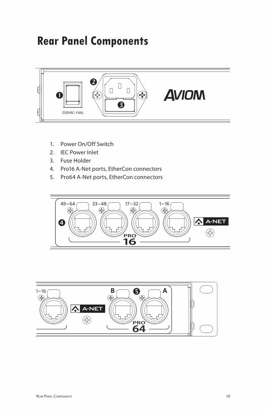
10reAr PANel comPoNeNts
1. Power On/Off Switch2. IEC Power Inlet3. Fuse Holder
Pro16 4. A‑Net ports, EtherCon connectors Pro64 5. A‑Net ports, EtherCon connectors
Rear Panel Components
11FroNt PANel FeAtures
Front Panel Features This section describes the features and functions of all front‑panel components of the ASI A‑Net Systems Interface.
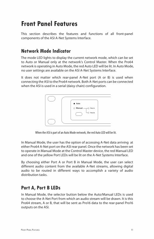
Network Mode Indicator The mode LED lights to display the current network mode, which can be set to Auto or Manual only at the network’s Control Master. When the Pro64 network is operating in Auto Mode, the red Auto LED will be lit. In Auto Mode, no user settings are available on the ASI A‑Net Systems Interface.
It does not matter which rear‑panel A‑Net port (A or B) is used when connecting the ASI to the Pro64 network. Both A‑Net ports can be connected when the ASI is used in a serial (daisy chain) configuration.
When the ASI is part of an Auto Mode network, the red Auto LED will be lit.
In Manual Mode, the user has the option of accessing A‑Net data arriving at either Pro64 A‑Net port on the ASI rear panel. Once the network has been set to operate in Manual Mode at the Control Master device, the red Manual LED and one of the yellow Port LEDs will be lit on the A‑Net Systems Interface.
By choosing either Port A or Port B in Manual Mode, the user can select different audio content from the available A‑Net streams, allowing digital audio to be routed in different ways to accomplish a variety of audio distribution tasks.
Port A, Port B LEDs In Manual Mode, the selector button below the Auto/Manual LEDs is used to choose the A‑Net Port from which an audio stream will be drawn. It is this Pro64 stream, A or B, that will be sent as Pro16 data to the rear‑panel Pro16 outputs on the ASI.

12FroNt PANel FeAtures
In the example below, the network is operating in Manual Mode, and data from Pro64 Port B will be sent to the Pro16 outputs.
Port B has been selected in Manual Mode as the source of the Pro64 data to be output in the Pro16 format.
Pro64 Network Sample RateWhenever the ASI A‑Net Systems Interface is part of a valid Pro64 network, one of the Sample Rate LEDs will be lit. The Sample Rate LED will indicate the current sample rate range in use by the network. The actual sample rate is set at the Pro64 device designated as the Clock Master.
In this diagram, the Pro64 network is operating at the 2x range, 88.2/96kHz.
Pro64 networks can operate at sample rates in three ranges without the use of sample rate converters. The current network sample rate also determines the number of available A‑Net Slots.
Sample Rate Pro64 A-Net Slots Available
44.1/48kHz 64
88.2/96kHz 32
176.4/192kHz 16

13FroNt PANel FeAtures
In an all‑analog network, the sample rate can be set at the Control Master to the following:
44.1kHz•48• kHz88.2• kHz96• kHz176.4• kHz192• kHz
When an external clock is used with a Pro64 digital I/O device, the system can lock to any sample rate within one of the three ranges shown in the table below.
Pro64 Series Supported Sample Rates
Sample Rate Minimum Maximum
44.1/48kHz 39.7kHz 52kHz
88.2/96kHz 79.4kHz 104kHz
176.4/192kHz 158.8kHz 208kHz
Pro16 OutputsThe current Pro64 sample rate has a direct effect on the number of Pro16 channels that can be output from the A‑Net Systems Interface. The Pro16 outputs are in banks of sixteen channels.
Pro64 Sample Rate Pro16 Outputs Available
44.1kHz 1‑16, 17‑32, 33‑48, 49‑64
48kHz 1‑16, 17‑32, 33‑48, 49‑64
88.2kHz 1‑16, 17‑32
96kHz 1‑16, 17‑32
176.4kHz 1‑16
192kHz 1‑16
The Pro16 Output LEDs on the front panel of the ASI will display the available Pro16 outputs, based on the current Pro64 network sample rate.
Pro64/Pro16 Channel MappingAt 44.1/48kHz, all four Pro16 outputs on the ASI can be used. Each is mapped in a one‑to‑one relationship to its Pro64 channel counterpart (Pro64 channel 1 is output as Pro16 channel 1; Pro64 channel 23 is output as Pro16 channel 23, etc.). No channel remapping is possible between the two data formats.

14FroNt PANel FeAtures
At 96kHz, only 32 channels are output to the rear‑panel Pro16 A‑Net outputs. Channels 33‑64 will have no data available. Pro16 devices connected to the 33‑48 and 49‑64 ports on the ASI will not output any data.
When a Pro64 network is running at the 2x (88.2/96kHz) rate, Pro16 devices should be connected to only the first two Pro16 output ports.
At 192kHz, only Pro64 channels 1‑16 are sent to the Pro16 outputs. Channels 17‑64 will have no Pro16 data available. Pro16 devices connected to the 17‑32, 33‑48, and 49‑64 ports will not output any data.
When a Pro64 network is running at the 4x (176.4/192kHz) sample rate, Pro16 devices should be connected to only the first Pro16 output port.
This diagram shows a Pro64 network operating at the 1x (44.1/48kHz) sample rate. Its 64 audio channels are available as Pro16 data in four banks of 16 at the rear-panel Pro16 outputs on the ASI. All four Pro16 Available Output LEDs are lit.
A-Net LEDThe blue LED found within the A‑Net logo functions as the network activity indicator. When a module is powered up, its A‑Net LED will flash while a request to enter the network is sent to and then processed by the Control Master.
15FroNt PANel FeAtures
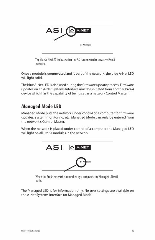
The blue A-Net LED indicates that the ASI is connected to an active Pro64 network.
Once a module is enumerated and is part of the network, the blue A‑Net LED will light solid.
The blue A‑Net LED is also used during the firmware update process. Firmware updates on an A‑Net Systems Interface must be initiated from another Pro64 device which has the capability of being set as a network Control Master.
Managed Mode LEDManaged Mode puts the network under control of a computer for firmware updates, system monitoring, etc. Managed Mode can only be entered from the network’s Control Master.
When the network is placed under control of a computer the Managed LED will light on all Pro64 modules in the network.
When the Pro64 network is controlled by a computer, the Managed LED will be lit.
The Managed LED is for information only. No user settings are available on the A‑Net Systems Interface for Managed Mode.

16reAr PANel FeAtures
Rear Panel Features All ASI rear‑panel features and functions are described in this section.
AC Power Pro64 modules use switching power supplies that can operate at 100‑240V, and from 50‑60Hz, meaning that they can be used with most of the world’s AC power systems by simply changing the line cord. The ASI is equipped with a standard grounded IEC power inlet (with fuse) which can accept the interchangeable IEC power cord.
The ASI uses a standard detachable IEC power cable. The AC inlet also contains the fuse compartment.
FuseThe fuse holder is spring‑loaded and has space for two fuses, one main and one spare (optional). Press the fuse holder cover to access the fuse. When checking or replacing a fuse, always power off the Pro64 unit and remove the line cord from the AC power source.
Always replace the fuse with one of the same rating as that being changed.
A-Net Ports Six EtherCon jacks are provided for A‑Net connections, two bidirectional Pro64 I/O ports and four Pro16 outputs. Connections can use standard RJ45‑style cables or cables outfitted with the locking Neutrik EtherCon connector.
Pro64 PortsTwo Pro64 A‑Net ports are provided, labeled A and B. The actual functionality of the Pro64 ports is determined by the current network mode (Auto or Manual) and the setting of the Manual Mode configuration when using Manual Mode.

17reAr PANel FeAtures
In Auto Mode, both Pro64 A‑Net ports are identical. Cables from any Pro64 device can be plugged into either port. Multiple ASI A‑Net Systems Interfaces can be used by connecting them to any available Pro64 A‑Net port, including those found on MH10 Merger Hub ports.
Two Pro64 ports provide connections to other Pro64 devices.
In Manual Mode, the Pro64 data source is determined by the port settings on the front panel of the ASI.
Pro16 PortsPro16 data is output though the four Pro16 ports on the ASI. The current Pro64 network sample rate determines which Pro16 ports will be active. See the section on Pro16 Output for additional information.
Pro64 data is output to Pro16 devices in blocks of sixteen channels.
Note: The Pro16 ports on the ASI are outputs only. Do not connect the A‑Net outputs from Pro16 input modules (including console cards) to these ports. Pro16 data streams cannot be translated into Pro64 data using the ASI.

18Asi coNNectioNs
ASI Connections Building a Pro64 network involves connecting input and output modules, setting A‑Net Slot ranges, and activating input channels. When added to a Pro64 network, the ASI A‑Net Systems Interface will output Pro16 compatible data from all active Pro64 channels. The maximum number of available Pro16 channels is determined by the current Pro64 sample rate.
The ASI can be connected to any available A‑Net port on a Pro64 I/O module or merger hub such as the MH10.
Connecting Pro64 ModulesTo create a network, set one (and only one) device to be the network Control Master. Because there are some operations that can only be executed at the Control Master, be sure that the module designated as the Control Master is accessible. Once all modules in the network are enumerated (indicated by illuminated A‑Net LEDs), choose a network mode (Auto/Manual), set A‑Net Slot ranges on each module, and activate audio channels and VDCs as needed.
Pro64 Series Connections
B A
B A
Input
B A
Output
B A
Input
B A
Output
B A
Input
B A
Input
B A
Output
1 2
Merger
3 4 5 6 7 8 9 10
B A
B A
Input
B A
Output
B A
Input
B A
Output
B A
Input
B A
Input
B A
Output
1 2
Merger
3 4 5 6 7 8 9 10B A
B A
Input
B A
Output
B A
Input
B A
Output
B A
Input
B A
Input
B A
Output
1 2
Merger
3 4 5 6 7 8 9 10
B A
B A
Input
B A
Output
B A
Input
B A
Output
B A
Input
B A
Input
B A
Output
1 2
Merger
3 4 5 6 7 8 9 10
1 2
Merger
3 4 5 6 7 8 9 10
A BPro16Pro64
A-Net Systems Interface
1-16 17-32 33-48 49-64
The ASI is shown connected to Pro64 modules in series.

19Asi coNNectioNs
Pro64 Parallel ConnectionsThe ASI can be connected to any available port on an MH10 Merger Hub that is part of the Pro64 network.
B A
B A
Input
B A
Output
B A
Input
B A
Output
B A
Input
B A
Input
B A
Output
1 2
Merger
3 4 5 6 7 8 9 10
B A
B A
Input
B A
Output
B A
Input
B A
Output
B A
Input
B A
Input
B A
Output
1 2
Merger
3 4 5 6 7 8 9 10
B A
B A
Input
B A
Output
B A
Input
B A
Output
B A
Input
B A
Input
B A
Output
1 2
Merger
3 4 5 6 7 8 9 10
B A
B A
Inp
ut
B A
Outp
ut
B A
Inp
ut
B A
Outp
ut
B A
Inp
ut
B A
Inp
ut
B A
Outp
ut
12
Merg
er
34
56
78
910
1 2
Merger
3 4 5 6 7 8 9 10
A BPro16Pro64
A-Net Systems Interface
1-16 17-32 33-48 49-64
This diagram shows the ASI connected to a Merger Hub in parallel.
Channel RoutingTo use the audio inputs connected to Pro64 input modules with Pro16 Personal Mixers via the ASI, connect audio signals in blocks of sixteen channels that will map in a useful manner to the Pro16 devices. Each group of sixteen Pro64 channels (1‑16, 17‑32, etc.) becomes a separate Pro16 stream when output from the ASI. No remapping of channels is possible within the A‑Net Systems Interface.
Connecting Pro16 Modules Any Pro16 Series device with an available A‑Net In port can be connected to the ASI.
Pro16 Series input modules (such as the AN‑16/i or AN‑16/i‑M) or console interface cards (such as the Y1 card for Yamaha® digital consoles) should not be connected to the ASI A‑Net Systems Interface.
Note: The ASI does not translate Pro16 Series A‑Net data into Pro64 Series data. Do not connect the A‑Net outputs from Pro16 Series modules to the Pro16 or Pro64 ports on the ASI.

20Asi coNNectioNs
Compatible Pro16 Series devices include:•A‑16II Personal Mixer •A‑16R rack‑mount Personal Mixer •AN‑16/o Output Module
A‑16D A‑Net Distributor •A‑16D Pro A‑Net Distributor •AN‑16SBR • System Bridge
Connecting Personal MixersTo connect Pro16 Series Personal Mixers to the ASI, serial or parallel connections can be used. Remember that each Pro64 data stream that is output from the A‑Net Systems Interface contains unique data, meaning that up to four discrete monitoring systems can be connected at a time (at the Pro64 48kHz sample rate).
Pro16 Series ConnectionsTo connect a Personal Mixer to the ASI, connect one port on the ASI (for example channels 1‑16) to the A‑Net In on the Personal Mixer. Connect additional Personal Mixers as needed by daisy chaining or in parallel with an A‑Net Distributor.
1 2
Merger
3 4 5 6 7 8 9 10
A BPro16Pro64
A-Net Systems Interface
1-16 17-32 33-48 49-64
PersonalMixer
System Bridge
Pro16 Output Module
A B C D
System Bridge
A B C D
Pro16 A-Net Distributor
1 2 3 4 5 6 7 8
PersonalMixer
System Bridge
Pro16 Output Module
A B C D
System Bridge
A B C D
Pro16 A-Net Distributor
1 2 3 4 5 6 7 8
The ASI, connected to a Pro64 network via Port A, sends channels 1-16 to a group of Pro16 Personal Mixers connected in series. An unlimited number of Personal Mixers can be connected in series.
Connecting Personal Mixers in Parallel Any Pro16 output on the A‑Net Systems Interface can be connected to a Pro16 A‑Net Distributor to allow parallel connection of Pro16 Series devices.

21Asi coNNectioNs
PersonalMixer
System Bridge
Pro16 Output Module
A B C D
System Bridge
A B C D
Pro16 A-Net Distributor
1 2 3 4 5 6 7 8
PersonalMixer
System Bridge
Pro16 Output Module
A B C D
System Bridge
A B C D
Pro16 A-Net Distributor
1 2 3 4 5 6 7 8
1 2
Merger
3 4 5 6 7 8 9 10
A BPro16Pro64
A-Net Systems Interface
1-16 17-32 33-48 49-64
PersonalMixer
System Bridge
Pro16 Output Module
A B C D
System Bridge
A B C D
Pro16 A-Net Distributor
1 2 3 4 5 6 7 8
PersonalMixer
System Bridge
Pro16 Output Module
A B C D
System Bridge
A B C D
Pro16 A-Net Distributor
1 2 3 4 5 6 7 8
Pro16 channels 1-16 output from the ASI are connected to an A-Net Distributor which feeds up to eight Personal Mixers in parallel.
Up to four unique monitor system feeds can be connected to the ASI, with each connected to its own A‑Net Distributor as illustrated above. The Pro16 cable runs shown can be up to 500 feet (150 meters) long between each Pro16 device.
Connecting Pro16 Output Modules When distributing Pro64 audio with Pro16 output modules, the Pro16 Series modules can be connected in series or in parallel to create digital copies and splits. In addition, the Pro16 System Bridge products, the AN‑16SB and AN‑16SBR, can be used to combine up to four Pro16 data streams so that they can be transferred over a single Cat‑5e cable.
PersonalMixer
System Bridge
Pro16 Output Module
A B C D
System Bridge
A B C D
Pro16 A-Net Distributor
1 2 3 4 5 6 7 8
1 2
Merger
3 4 5 6 7 8 9 10
A BPro16Pro64
A-Net Systems Interface
1-16 17-32 33-48 49-64
PersonalMixer
System Bridge
Pro16 Output Module
A B C D
System Bridge
A B C D
Pro16 A-Net Distributor
1 2 3 4 5 6 7 8
The ASI is connected to a series of AN-16/o Output Modules. Here, channels 33-48 are being output; the Pro64 sample rate is 48kHz.

22Asi coNNectioNs
Using a System Bridge The Pro16 System Bridge is used to combine up to four Pro16 data streams for transmission over a single Cat‑5e cable. This setup simplifies digital snakes, saves cable, and is easy to install.
At the Pro64 1x sample rate of 44.1/48kHz, four unique streams of Pro16 data are available from the A‑Net Systems Interface. The following example shows the use of a System Bridge connected to the ASI.
Pers
onal
Mix
er
Syst
em B
rid
ge
Pro1
6 O
utp
ut M
odul
e
A
B
C
D
Syst
em B
rid
ge
A
B
C
D
Pro1
6 A
-Net
Dis
trib
utor
1
2
3
4
5
6
7
8
1 2
Merger
3 4 5 6 7 8 9 10
A BPro16Pro64
A-Net Systems Interface
1-16 17-32 33-48 49-64
PersonalMixer
System Bridge
Pro16 Output Module
A B C D
System Bridge
A B C D
Pro16 A-Net Distributor
1 2 3 4 5 6 7 8
PersonalMixer
System Bridge
Pro16 Output Module
A B C D
System Bridge
A B C D
Pro16 A-Net Distributor
1 2 3 4 5 6 7 8
Pers
onal
Mix
er
Syst
em B
rid
ge
Pro1
6 O
utp
ut M
odul
e
A
B
C
D
Syst
em B
rid
ge
A
B
C
D
Pro1
6 A
-Net
Dis
trib
utor
1
2
3
4
5
6
7
8
Pers
onal
Mix
er
Syst
em B
rid
ge
Pro1
6 O
utp
ut M
odul
e
A
B
C
D
Syst
em B
rid
ge
A
B
C
D
Pro1
6 A
-Net
Dis
trib
utor
1
2
3
4
5
6
7
8
Pers
onal
Mix
er
Syst
em B
rid
ge
Pro1
6 O
utp
ut M
odul
e
A
B
C
D
Syst
em B
rid
ge
A
B
C
D
Pro1
6 A
-Net
Dis
trib
utor
1
2
3
4
5
6
7
8
1‑16 17‑32 33‑48 49‑64
The System Bridge allows four Pro16 devices to be connected with only one Cat-5e cable. Each AN-16/o module outputs a unique set of channels.
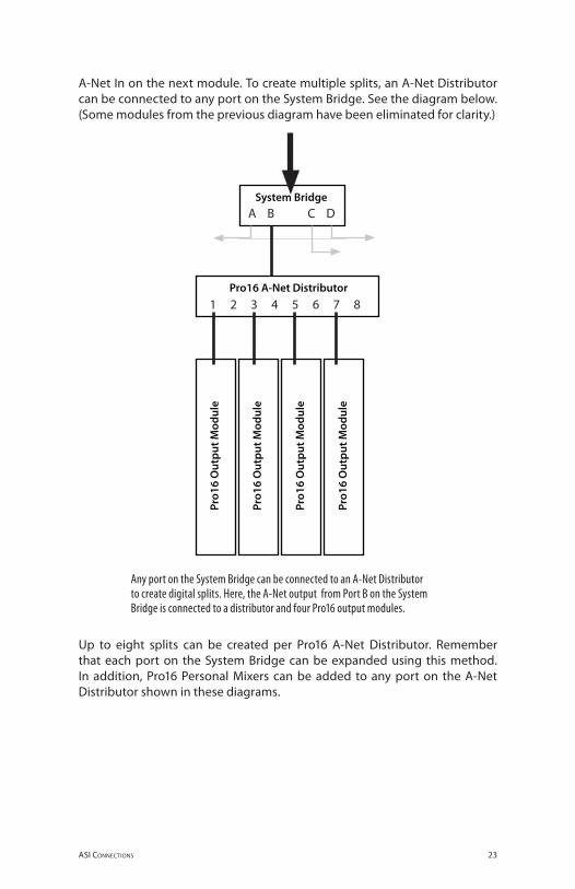
Four AN‑16/o Output Modules are shown in the diagram above, each connected to an ASI using a pair of System Bridges. Each AN‑16/o module outputs one 16‑channel block of audio channels from the Pro64 system (1‑16, 17‑32, etc.). Additional Pro16 output modules can be added to create digital splits and copies by connecting the A‑Net Out port on the AN‑16/o to the
23Asi coNNectioNs
A‑Net In on the next module. To create multiple splits, an A‑Net Distributor can be connected to any port on the System Bridge. See the diagram below. (Some modules from the previous diagram have been eliminated for clarity.)
PersonalMixer
System Bridge
Pro16 Output Module
A B C D
System Bridge
A B C D
Pro16 A-Net Distributor
1 2 3 4 5 6 7 8 Pe
rson
alM
ixer
Syst
em B
rid
ge
Pro1
6 O
utp
ut M
odul
e
A
B
C
D
Syst
em B
rid
ge
A
B
C
D
Pro1
6 A
-Net
Dis
trib
utor
1
2
3
4
5
6
7
8
PersonalMixer
System Bridge
Pro16 Output Module
A B C D
System Bridge
A B C D
Pro16 A-Net Distributor
1 2 3 4 5 6 7 8
Pers
onal
Mix
er
Syst
em B
rid
ge
Pro1
6 O
utp
ut M
odul
e
A
B
C
D
Syst
em B
rid
ge
A
B
C
D
Pro1
6 A
-Net
Dis
trib
utor
1
2
3
4
5
6
7
8
Pers
onal
Mix
er
Syst
em B
rid
ge
Pro1
6 O
utp
ut M
odul
e
A
B
C
D
Syst
em B
rid
ge
A
B
C
D
Pro1
6 A
-Net
Dis
trib
utor
1
2
3
4
5
6
7
8
Pers
onal
Mix
er
Syst
em B
rid
ge
Pro1
6 O
utp
ut M
odul
e
A
B
C
D
Syst
em B
rid
ge
A
B
C
D
Pro1
6 A
-Net
Dis
trib
utor
1
2
3
4
5
6
7
8
Any port on the System Bridge can be connected to an A-Net Distributor to create digital splits. Here, the A-Net output from Port B on the System Bridge is connected to a distributor and four Pro16 output modules.
Up to eight splits can be created per Pro16 A‑Net Distributor. Remember that each port on the System Bridge can be expanded using this method. In addition, Pro16 Personal Mixers can be added to any port on the A‑Net Distributor shown in these diagrams.

24sPeciFicAtioNs
SpecificationsA-Net I/O - Pro64 2 EtherCon RJ45 connectors
Network Sample Rates, Pro64
44.1/48kHz; 88.2/96kHz; 176.4/192kHz ± (see below)
Sample Rate Range, Pro64
1x 44.1/48kHz, 39.7kHz to 52kHz 2x 88.2/96kHz, 79.4kHz to 104kHz 4x 176.4/192kHz, 158.8kHz to 208kHz
A-Net Out - Pro16 4 EtherCon RJ45 connectors
Pro16 Outputs Channels 1‑16 Channels 17‑32 Channels 33‑48 Channels 49‑64
Bit Depth 24‑bits
Network Latency Total latency is less than 1ms (measured from analog in to analog out)
Cable Length, Cat-5e, Pro64 network
Maximum 400 feet (120 meters); Use Unshielded Twisted Pair (UTP) cable
Cable Length, Cat-5e, Pro16 network
Maximum 500 feet (150 meters); Use Unshielded Twisted Pair (UTP) cable
Power Supply 100‑240VAC 50‑60Hz, 24W
Internal switching power supply; IEC connector
Fuse F4AL
Dimensions 1U; 19”w x 8”d x 1.75”h 482.6 x 203 x 44 mm
Weight 5.5 pounds; 2.49 kg
All Aviom products are designed and manufactured in the USA.

25sPeciFicAtioNs
Dimensions

26sPeciFicAtioNs
Pro6
4 A
-Net
64 C
hann
els
@44
.1/4
8kH
z
Cha
nnel
s 1-
16
Cha
nnel
s 17
-32
Cha
nnel
s 33
-48
Cha
nnel
s 49
-64
Pro1
6 A
-Net
Pro
64 C
ontro
l Log
ic
1-16
17-3
2 (4
4.1/
48, 8
8.2/
96 o
nly)
33-4
8 (4
4.1/
48 o
nly)
49-6
4 (4
4.1/
48 o
nly)
Pro
64 C
ontro
l Log
icP
ro64
Con
trol L
ogic
Pro
64 C
ontro
l Log
ic
Pro6
4 A
-Net
32 C
hann
els
@88
.1/9
6kH
z
Cha
nnel
s 1-
16
Cha
nnel
s 17
-32
Pro1
6 A
-Net
Pro6
4 A
-Net
16 C
hann
els
@17
6.2/
192k
Hz
Cha
nnel
s 1-
16Pr
o16
A-N
et
Sam
ple
Rat
eC
onve
rsio
nto
48k
Hz
Sam
ple
Rat
eC
onve
rsio
nto
48k
Hz
Pro
16A
-Net
Pro
64A
-Net
Sam
ple
rate
conv
erte
r (to
48k
Hz)
Sig
nal
-10d
BC
lip
Use
r C
onfig
. S
ettin
gs
to/fr
omne
twor
k
Block Diagram

27sPeciFicAtioNs
Pro64 A-Net64 [email protected]/48kHz
Channels 1-16
Channels 17-32
Channels 33-48
Channels 49-64
Pro16 A-Net
Pro64 Control Logic
1-16
17-32 (44.1/48, 88.2/96 only)
33-48 (44.1/48 only)
49-64 (44.1/48 only)
Pro64 Control LogicPro64 Control Logic
Pro64 Control Logic
Pro64 A-Net32 [email protected]/96kHz
Channels 1-16
Channels 17-32
Pro16 A-Net
Pro64 A-Net16 Channels
@176.2/192kHz
Channels 1-16Pro16 A-Net
Sample RateConversionto 48kHz
Sample RateConversionto 48kHz
Pro16A-Net
Pro64A-Net
Sample rateconverter (to 48kHz)
Signal -10dB Clip
User Config. Settings
to/fromnetwork

28iNdex
Index
AA‑16II, A‑16R
Personal Mixers 5A‑16II Personal Mixer 2, 20A‑16R Personal Mixer 2, 20About A‑Net 3A, B Ports
Pro64 11AC fuse
changing 16AC Line Conditioning 7AC Power 16AN‑16/i 19AN‑16/i‑M 19AN‑16/o 2, 20, 22AN‑16SBR 21A‑Net 1
Pro64 Series 3A‑Net Distributor 5
A‑16D, A‑16D Pro 2, 20A‑Net In 20
Pro16 19A‑Net I/O 24A‑Net LED 9, 13, 14, 15A‑Net Out 22
Pro16 19A‑Net Ports 4, 9, 16, 18
Pro16 2A‑Net Slot 12A‑Net Transmit 11ASI A‑Net Systems Interface 5audio inputs
Pro64 19Auto LED 11Auto/Manual Mode Selection 9Auto Mode 4, 11, 17
Bbidirectional 4Bit Depth 24
CCable Length 24
Pro16, Pro64 24Cables
Cat‑5e, Cat‑6 3cable specification, Cat‑5e 2Cat‑5
stranded vs. solid 2Cat‑5e 1, 2, 24
Pro16 cable length 21Unshielded Twisted Pair (UTP) 2UTP 24
Cat‑5e Cable Distance 3Cat‑6 2Certifications iiChannel Routing 19Channels
Pro16 24Cleaning 8Clock 3
external 13jitter and wander 3
Clock Master 4compatibility
Pro16 2, 5computer 2, 15Connecting Pro16 Modules 19Connecting Pro64 Modules 18console interface card 19Control Data 4Control Master 13, 15, 18
Ddaisy chain 11, 20DB9 cable
null modem 2Digital Copies 21digital split 21Dimensions 24, 25Distributors
Pro16 2
EEnter/Cancel button 11Enumeration 18EtherCon 1, 2, 16, 24Ethernet 3External Clock 13

29iNdex
Ffiber 3Firmware Update 2Front Panel Components 9Fuse 24
AC 16Fuse Holder 10
GGPIO
General Purpose I/O 4
HHub
MH10 Merger Hub 17
IIEC connector 24IEC power cord 16IEC Power Inlet 10input module
Pro16 19
Jjitter 3
LLatency 24LED
Port A, B 11
MManaged button 9, 15Managed LED 15Manual LED 11Manual Mode 4, 11, 17Manual Mode configurations 11Merger Hub 17MH10 17MH10f 3MH10 Merger Hub 18, 19MIDI 4Monitor Mixing System
Pro16 5, 21Mounting, Rack 7
Nnetwork mode
Auto, Manual 16Neutrik EtherCon. See EtherConnull modem cable
DB9 2
OOutput Module
AN‑16/o 20, 22Output Modules
Pro16 2
Pparallel 3Parallel Connections 19PC
software update 2Personal Mixer 19, 20, 23
A‑16II, A‑16R 5Pro16 2
Port A, B 11. See A-Net PortsPorts
A‑Net 4Power On/Off Switch 10Power Supply 16, 24Pro16 2
A‑Net In 19A‑Net Out 19A‑Net ports 2compatibility 2input module 17, 19monitor system 21output module 21sample rate range 1
Pro16 cable lengthCat‑5e 21
Pro16 data 21Pro16 Modules
Connecting 19Pro16 ports 17Pro16 Series 5Pro64 1, 3
A, B Ports 11Pro64/Pro16 Channel Mapping 13Pro64 Update Tool 2

30iNdex
RRear Panel Components 10RJ45 1, 2, 24RoHS iiRS‑232 4
null modem cable 2RS‑422 4
Ssample rate 20Sample Rate 2, 3
minimum/maximum 3, 13sample rate conversion 2, 4sample rate converter 12sample rate range
Pro16 1Sample Rate Range
Pro64 24serial 3Series Connections 18, 20series, parallel connections 20Slot 5Slot range 18Slots 12software update 15Specifications 24split 21, 23stranded vs. solid Cat‑5 2System Bridge 20, 22
UUnshielded Twisted Pair 2
UTP 24Update Tool 2UPS 7UTP 2UTP cable
Cat‑5e, Cat‑6 3
VVDC 2Ventilation 8Virtual Data Cables 4
Wwander 3Weight 24
YY1 card 19Yamaha 19

Warranty RegistrationPlease take a moment to fill in this warranty registration form. Return it to Aviom via mail or fax. All information will be kept confidential.
Model Number Product Serial Number
Model Number Product Serial Number
Model Number Product Serial Number
Model Number Product Serial Number
Date Purchased
Dealer Name
Dealer Location
Your Name
Address
Address
City
State/Province
Zip/Postal Code
Country
Email Address .
Fax this form to Aviom at +1 610‑738‑9950

1157 Phoenixville Pike, Suite 201 • West Chester, PA 19380 Voice: +1 610.738.9005 • Fax: +1 610.738.9950 • www.Aviom.com