Embed Size (px)
DESCRIPTION
A selection of most commonly used products which meet a wide range of applications and offer great reliability. ASCO Numatics Express Catalogue gives you clear and precise information to accompany you from selection to placing an order.
Citation preview
www.asconumatics.eu

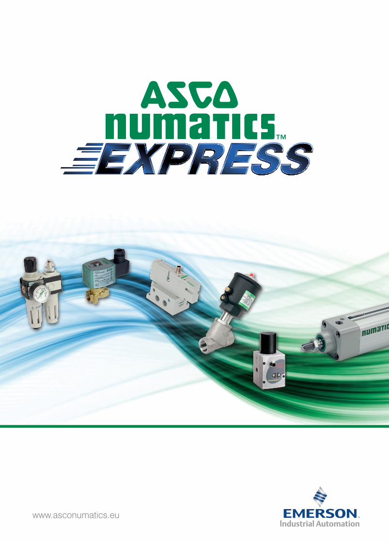
Motorised/Pressure operated valves 4
Solenoid valves 2/2 - 3/2 9-23
Cylinders 24
Magnetic position detectors 44
Solenoid pilot valves 47
Spool valves, poppet valves 51
Pneumatic valve islands 77
Proportional pneumatic control 82
Air service equipment 88
Pneumatic accessories 99
Connectors, coils 103
How to order 106
Index code/page 108
VALVES - SOLENOID VALVESPNEUMATIC COMPONENTS
For full terms and conditions please visit www.asconumatics.eu
4 www.asconumatics.eu
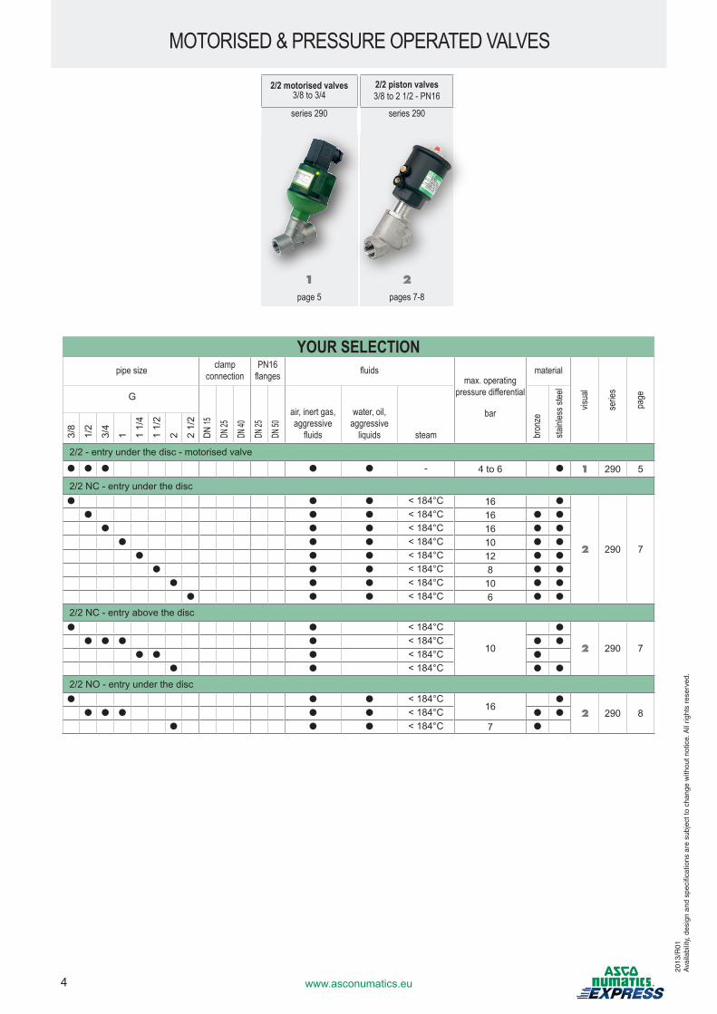
MOTORISED & PRESSURE OPERATED VALVES
2/2 motorised valves3/8 to 3/4
2/2 piston valves3/8 to 2 1/2 - PN16
series 290 series 290
1 2page 5 pages 7-8
YOUR SELECTION pipe size clamp
connectionPN16
flanges fluidsmax. operating
pressure differential
bar
material
visua
l
serie
s
page G
DN 15
DN 25
DN 40
DN 25
DN 50
air, inert gas, aggressive
fluids
water, oil, aggressive
liquids steam bron
ze
stainl
ess s
teel
3/8
1/2
3/4
1 1 1/
4
1 1/
2
2 2 1/
2
2/2 - entry under the disc - motorised valve
● ● ● ● ● - 4 to 6 ● 1 290 5
2/2 NC - entry under the disc● ● ● < 184°C 16 ●
2 290 7
● ● ● < 184°C 16 ● ●
● ● ● < 184°C 16 ● ●
● ● ● < 184°C 10 ● ●
● ● ● < 184°C 12 ● ●
● ● ● < 184°C 8 ● ●
● ● ● < 184°C 10 ● ●
● ● ● < 184°C 6 ● ●
2/2 NC - entry above the disc● ● < 184°C
10
●
2 290 7● ● ● ● < 184°C ● ●
● ● ● < 184°C ●
● ● < 184°C ● ●
2/2 NO - entry under the disc● ● ● < 184°C
16●
2 290 8● ● ● ● ● < 184°C ● ●
● ● ● < 184°C 7 ●
2013
/R01
Ava
ilabi
lity,
des
ign
and
spec
ifica
tions
are
sub
ject
to c
hang
e w
ithou
t not
ice.
All
right
s re
serv
ed.
5www.asconumatics.eu
YOUR SELECTION
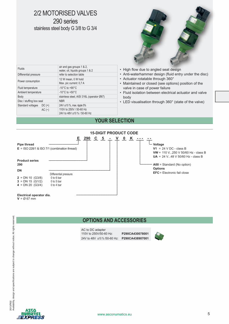
Fluids air and gas groups 1 & 2,water, oil, liquids groups 1 & 2
Differential pressure refer to selection table
Power consumption 12 W mean, 0 W holdMax. pic current: 0,7 A
Fluid temperature -10°C to +90°CAmbient temperature -10°C to +50°CBody stainless steel, AISI 316L (operator Ø67)Disc / stuffing box seal NBRStandard voltages DC (=) 24V ±10 %, max. ripple 5% AC (~) 110V to 250V / 50-60 Hz
24V to 48V ±10 % / 50-60 Hz
OPTIONS AND ACCESSORIES
2/2 MOTORISED VALVES290 series
stainless steel body G 3/8 to G 3/4
2013
/R02
Ava
ilabi
lity,
des
ign
and
spec
ifica
tions
are
sub
ject
to c
hang
e w
ithou
t not
ice.
All
right
s re
serv
ed.
• Highflowduetoangledseatdesign• Anti-waterhammerdesign(fluidentryunderthedisc)• Actuatorrotatablethrough360°• Maintainedorclosed(seeoptions)positionofthevalveincaseofpowerfailure
• Fluidisolationbetweenelectricalactuatorandvalvebody
• LEDvisualisationthrough360°(stateofthevalve)
15-DIGIT PRODUCT CODEE 290 C 5 - V 0 K - - - - -
Pipe thread VoltageE =ISO228/1&ISO7/1(combinationthread) V1 = 24VDC-classB
VW= 110V...250V50/60Hz-classBUA = 24V...48V50/60Hz-classB
Product series290 A00 = Standard(Nooption)
OptionsDNEFC = ElectronicfailcloseDifferential pressure
2 =DN10 (G3/8) 0 to 6 bar3 =DN15 (G1/2) 0 to 5 bar4 =DN20 (G3/4) 0 to 4 bar
Electrical operator dia.V = Ø 67 mm
ACtoDCadapter110Vto250V/50-60Hz: P290CA43007800124V to 48V ±10 % /50-60Hz: P290CA438907001
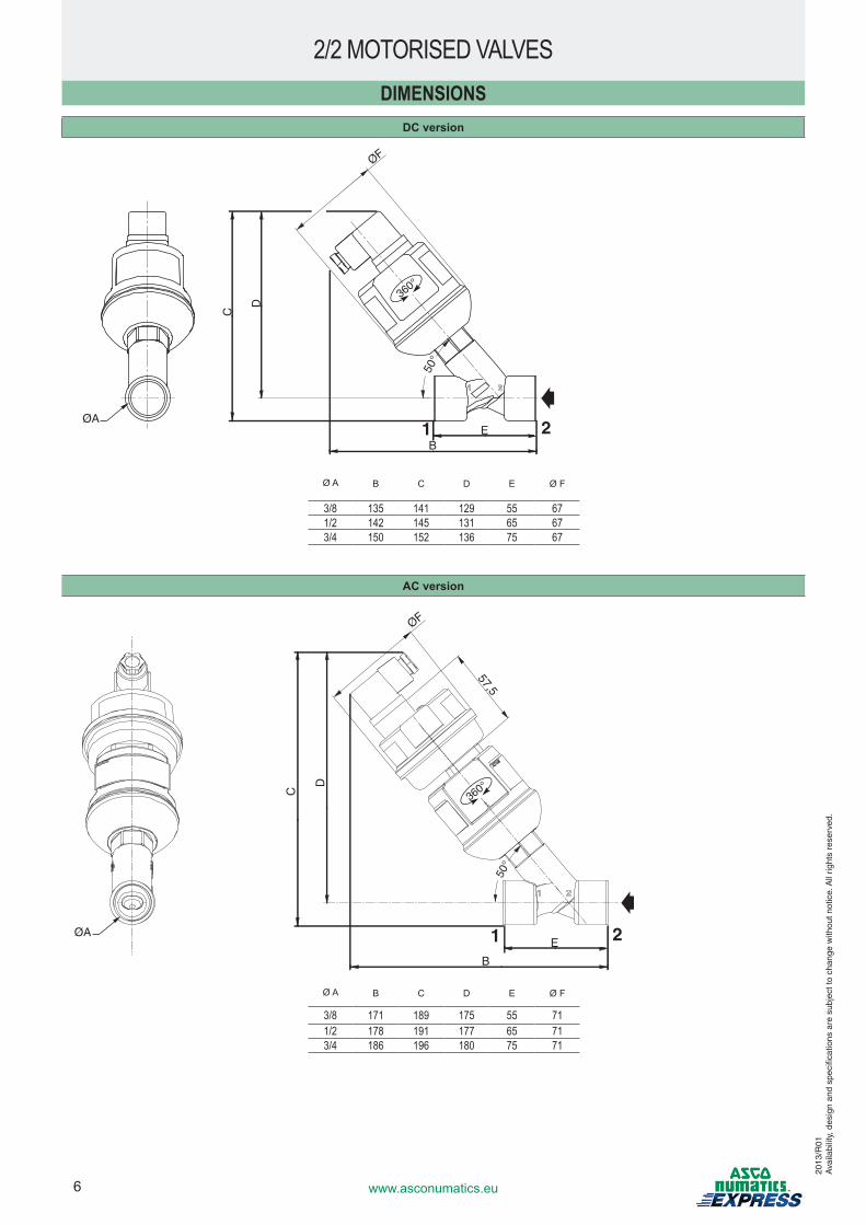
6 www.asconumatics.eu
DIMENSIONS
C
ØF
ØA
D
EB
50°
1 2
360°C
ØF
57,5
ØA
D
E
B
50°
1 2
360°
ØA B C D E ØF
3/8 171 189 175 55 711/2 178 191 177 65 713/4 186 196 180 75 71
DC version
ØA B C D E ØF
3/8 135 141 129 55 671/2 142 145 131 65 673/4 150 152 136 75 67
AC version
2/2 MOTORISED VALVES
2013
/R01
Ava
ilabi
lity,
des
ign
and
spec
ifica
tions
are
sub
ject
to c
hang
e w
ithou
t not
ice.
All
right
s re
serv
ed.
7www.asconumatics.eu
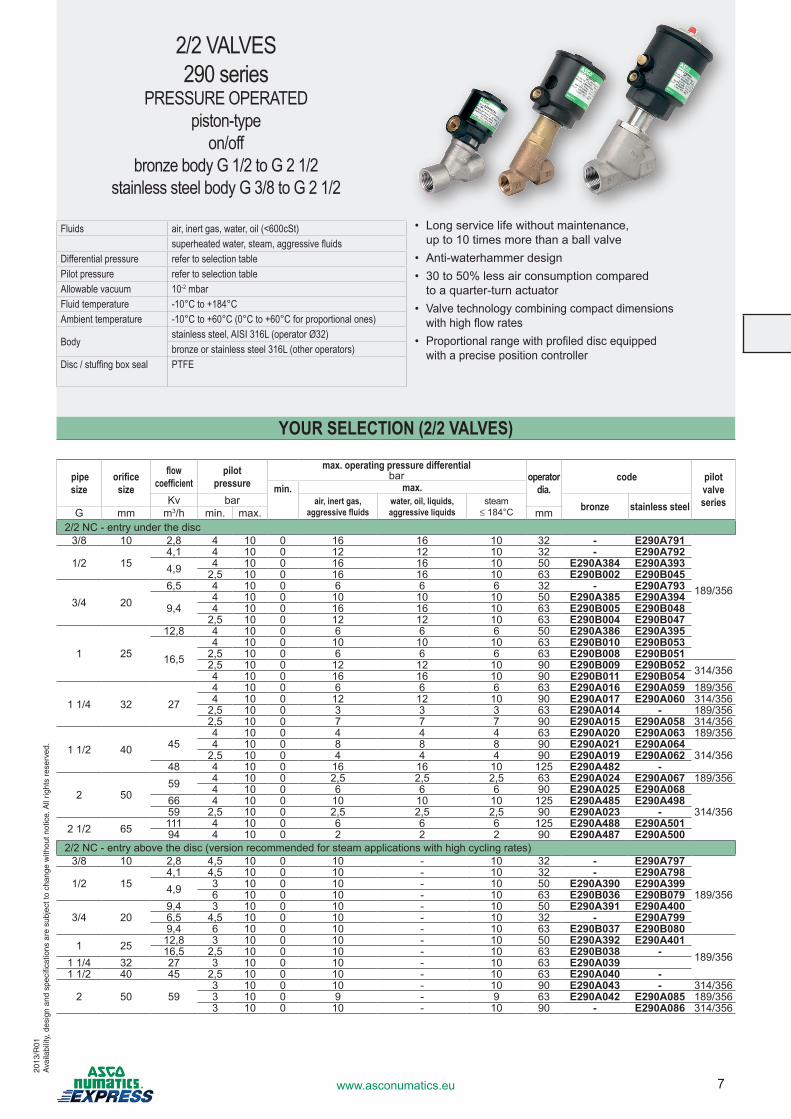
Fluids air, inert gas, water, oil (<600cSt)superheated water, steam, aggressive fluids
Differential pressure refer to selection tablePilot pressure refer to selection tableAllowable vacuum 10-2 mbarFluid temperature -10°C to +184°CAmbient temperature -10°C to +60°C (0°C to +60°C for proportional ones)
Bodystainless steel, AISI 316L (operator Ø32)bronze or stainless steel 316L (other operators)
Disc / stuffing box seal PTFE
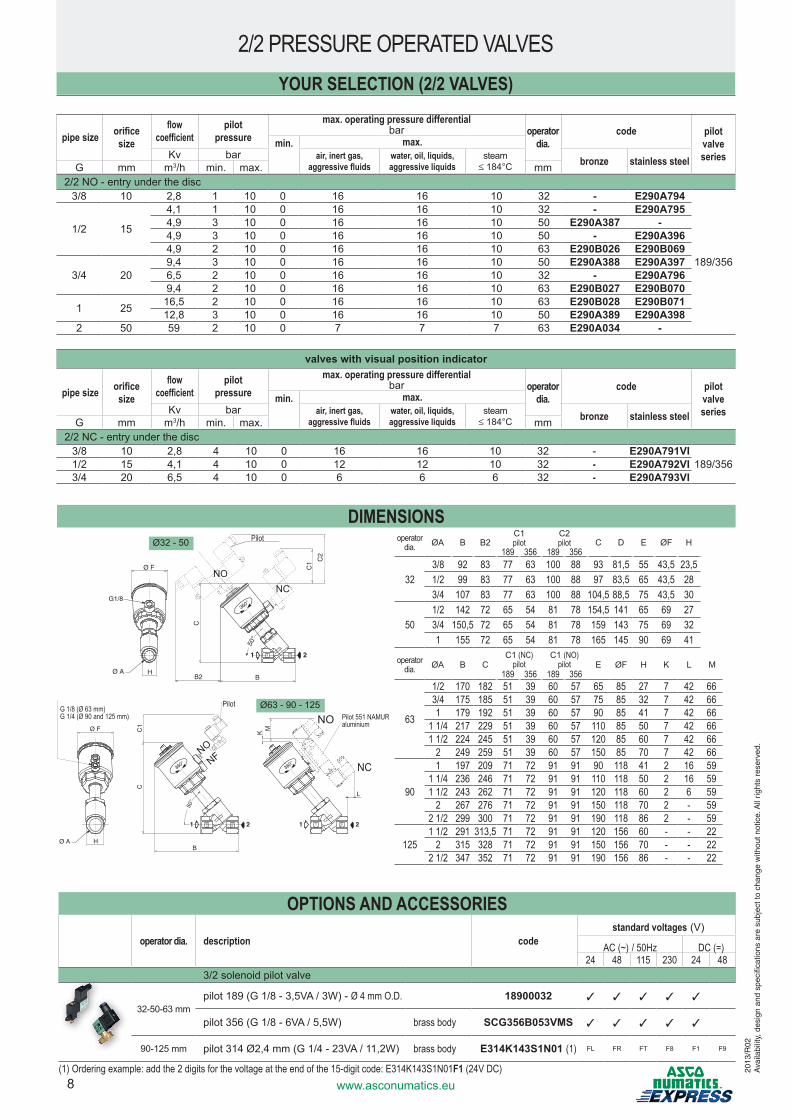
YOUR SELECTION (2/2 VALVES)
pipe size
orificesize
flow coefficient
pilotpressure
max. operating pressure differentialoperator
dia.code pilot
valve series
barmin. max.
Kv bar air, inert gas, aggressive fluids
water, oil, liquids, aggressive liquids
steam≤ 184°C bronze stainless steelG mm m3/h min. max. mm
2/2 NC - entry under the disc3/8 10 2,8 4 10 0 16 16 10 32 - E290A791
189/356
1/2 154,1 4 10 0 12 12 10 32 - E290A7924,9 4 10 0 16 16 10 50 E290A384 E290A393
2,5 10 0 16 16 10 63 E290B002 E290B045
3/4 206,5 4 10 0 6 6 6 32 - E290A793
9,44 10 0 10 10 10 50 E290A385 E290A3944 10 0 16 16 10 63 E290B005 E290B048
2,5 10 0 12 12 10 63 E290B004 E290B047
1 25
12,8 4 10 0 6 6 6 50 E290A386 E290A395
16,54 10 0 10 10 10 63 E290B010 E290B053
2,5 10 0 6 6 6 63 E290B008 E290B0512,5 10 0 12 12 10 90 E290B009 E290B052 314/3564 10 0 16 16 10 90 E290B011 E290B054
1 1/4 32 274 10 0 6 6 6 63 E290A016 E290A059 189/3564 10 0 12 12 10 90 E290A017 E290A060 314/356
2,5 10 0 3 3 3 63 E290A014 - 189/3562,5 10 0 7 7 7 90 E290A015 E290A058 314/356
1 1/2 40 454 10 0 4 4 4 63 E290A020 E290A063 189/3564 10 0 8 8 8 90 E290A021 E290A064
314/3562,5 10 0 4 4 4 90 E290A019 E290A06248 4 10 0 16 16 10 125 E290A482 -
2 5059 4 10 0 2,5 2,5 2,5 63 E290A024 E290A067 189/356
4 10 0 6 6 6 90 E290A025 E290A068
314/35666 4 10 0 10 10 10 125 E290A485 E290A49859 2,5 10 0 2,5 2,5 2,5 90 E290A023 -
2 1/2 65 111 4 10 0 6 6 6 125 E290A488 E290A50194 4 10 0 2 2 2 90 E290A487 E290A500
2/2NC-entryabovethedisc(versionrecommendedforsteamapplicationswithhighcyclingrates)3/8 10 2,8 4,5 10 0 10 - 10 32 - E290A797
189/3561/2 15
4,1 4,5 10 0 10 - 10 32 - E290A7984,9 3 10 0 10 - 10 50 E290A390 E290A399
6 10 0 10 - 10 63 E290B036 E290B079
3/4 209,4 3 10 0 10 - 10 50 E290A391 E290A4006,5 4,5 10 0 10 - 10 32 - E290A7999,4 6 10 0 10 - 10 63 E290B037 E290B080
1 25 12,8 3 10 0 10 - 10 50 E290A392 E290A401189/35616,5 2,5 10 0 10 - 10 63 E290B038 -
1 1/4 32 27 3 10 0 10 - 10 63 E290A0391 1/2 40 45 2,5 10 0 10 - 10 63 E290A040 -
2 50 593 10 0 10 - 10 90 E290A043 - 314/3563 10 0 9 - 9 63 E290A042 E290A085 189/3563 10 0 10 - 10 90 - E290A086 314/356
• Longservicelifewithoutmaintenance, upto10timesmorethanaballvalve
• Anti-waterhammerdesign• 30to50%lessairconsumptioncompared
to a quarter-turn actuator• Valvetechnologycombiningcompactdimensions withhighflowrates
• Proportionalrangewithprofileddiscequipped withaprecisepositioncontroller
2/2 VALVES290 series
PRESSURE OPERATEDpiston-type
on/offbronze body G 1/2 to G 2 1/2
stainless steel body G 3/8 to G 2 1/2
2013
/R01
Ava
ilabi
lity,
des
ign
and
spec
ifica
tions
are
sub
ject
to c
hang
e w
ithou
t not
ice.
All
right
s re
serv
ed.
8 www.asconumatics.eu
operator dia. description codestandard voltages(V)
AC (~) / 50Hz DC (=)24 48 115 230 24 48
3/2solenoidpilotvalve
32-50-63 mmpilot189(G1/8-3,5VA/3W)-Ø 4 mm O.D. 18900032 3 3 3 3 3
pilot356(G1/8-6VA/5,5W) brass body SCG356B053VMS 3 3 3 3 3
90-125 mm pilot314Ø2,4mm(G1/4-23VA/11,2W) brass body E314K143S1N01 (1) FL FR FT F8 F1 F9
(1) Ordering example: add the 2 digits for the voltage at the end of the 15-digit code: E314K143S1N01F1 (24V DC)
2/2 NO - entry under the disc3/8 10 2,8 1 10 0 16 16 10 32 - E290A794
189/356
1/2 15
4,1 1 10 0 16 16 10 32 - E290A7954,9 3 10 0 16 16 10 50 E290A387 -4,9 3 10 0 16 16 10 50 - E290A3964,9 2 10 0 16 16 10 63 E290B026 E290B069
3/4 209,4 3 10 0 16 16 10 50 E290A388 E290A3976,5 2 10 0 16 16 10 32 - E290A7969,4 2 10 0 16 16 10 63 E290B027 E290B070
1 25 16,5 2 10 0 16 16 10 63 E290B028 E290B07112,8 3 10 0 16 16 10 50 E290A389 E290A398
2 50 59 2 10 0 7 7 7 63 E290A034 -
valves with visual position indicator
pipe size orificesize
flow coefficient
pilotpressure
max. operating pressure differentialoperator
dia.code pilot
valve series
barmin. max.
Kv bar air, inert gas, aggressive fluids
water, oil, liquids,aggressive liquids
steam≤ 184°C bronze stainless steelG mm m3/h min. max. mm
2/2 NC - entry under the disc3/8 10 2,8 4 10 0 16 16 10 32 - E290A791VI
189/3561/2 15 4,1 4 10 0 12 12 10 32 - E290A792VI3/4 20 6,5 4 10 0 6 6 6 32 - E290A793VI
pipe size orificesize
flow coefficient
pilotpressure
max. operating pressure differentialoperator
dia.code pilot
valve series
barmin. max.
Kv bar air, inert gas, aggressive fluids
water, oil, liquids,aggressive liquids
steam≤ 184°C bronze stainless steelG mm m3/h min. max. mm
YOUR SELECTION (2/2 VALVES)
2/2 PRESSURE OPERATED VALVES
DIMENSIONSØ32 - 50
360°
CC
1
H B
50°
Ø F
Ø A
1 2
360°
1 2
K
L
M
G 1/8 (Ø 63 mm)G 1/4 (Ø 90 and 125 mm)
NONF
Pilot 551 NAMUR aluminium
NC
NOPilot
operatordia. ØA B C
C1 (NC)pilot
C1 (NO)pilot E ØF H K L M
189 356 189 356
63
1/2 170 182 51 39 60 57 65 85 27 7 42 663/4 175 185 51 39 60 57 75 85 32 7 42 661 179 192 51 39 60 57 90 85 41 7 42 66
1 1/4 217 229 51 39 60 57 110 85 50 7 42 661 1/2 224 245 51 39 60 57 120 85 60 7 42 66
2 249 259 51 39 60 57 150 85 70 7 42 66
90
1 197 209 71 72 91 91 90 118 41 2 16 591 1/4 236 246 71 72 91 91 110 118 50 2 16 591 1/2 243 262 71 72 91 91 120 118 60 2 6 59
2 267 276 71 72 91 91 150 118 70 2 - 592 1/2 299 300 71 72 91 91 190 118 86 2 - 59
1251 1/2 291 313,5 71 72 91 91 120 156 60 - - 22
2 315 328 71 72 91 91 150 156 70 - - 222 1/2 347 352 71 72 91 91 190 156 86 - - 22
G1/8
Ø A H
Ø F
360°
C
50°
B
C1
B2
C2
1 2
NONC
Ø63 - 90 - 125
operatordia. ØA B B2
C1pilot
C2pilot C D E ØF H
189 356 189 356
323/8 92 83 77 63 100 88 93 81,5 55 43,5 23,51/2 99 83 77 63 100 88 97 83,5 65 43,5 283/4 107 83 77 63 100 88 104,5 88,5 75 43,5 30
501/2 142 72 65 54 81 78 154,5 141 65 69 273/4 150,5 72 65 54 81 78 159 143 75 69 321 155 72 65 54 81 78 165 145 90 69 41
Pilot
OPTIONS AND ACCESSORIES
2013
/R02
Ava
ilabi
lity,
des
ign
and
spec
ifica
tions
are
sub
ject
to c
hang
e w
ithou
t not
ice.
All
right
s re
serv
ed.
9www.asconumatics.eu
2/2 SOLENOID VALVES20
13/R
02A
vaila
bilit
y, d
esig
n an
d sp
ecifi
catio
ns a
re s
ubje
ct to
cha
nge
with
out n
otic
e. A
ll rig
hts
rese
rved
.
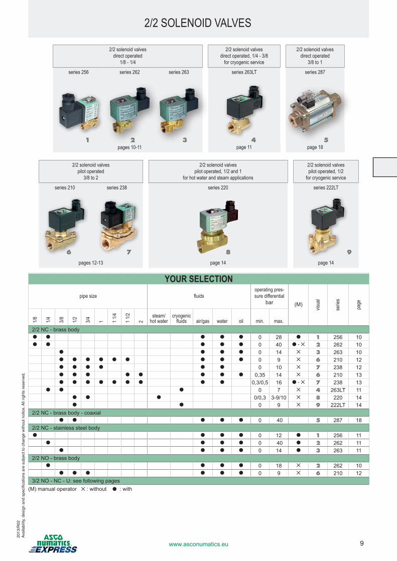
2/2 solenoid valvesdirect operated
1/8 - 1/4
2/2 solenoid valvesdirect operated, 1/4 - 3/8
for cryogenic service
2/2 solenoid valvesdirect operated
3/8 to 1
series 256 series 262 series 263 series 263LT series 287
pages 10-11 page 11 page 18
2/2 solenoid valvespilot operated
3/8 to 2
2/2 solenoid valvespilot operated, 1/2 and 1
for hot water and steam applications
2/2 solenoid valvespilot operated, 1/2
for cryogenic service
series 210 series 238 series 220 series 222LT
pages 12-13 page 14 page 14
YOUR SELECTION pipe size fluids
operating pres-sure differential
bar (M)
visua
l
serie
s
page
1/8 1/4 3/8 1/2 3/4 1 1 1/4
1 1/2
2
steam/ hot water
cryogenic fluids air/gas water oil min. max.
2/2 NC - brass body● ● ● ● ● 0 28 ● 1 256 10● ● ● ● ● 0 40 ● - ✕ 2 262 10
● ● ● ● 0 14 ✕ 3 263 10● ● ● ● ● ● ● ● ● 0 9 ✕ 6 210 12● ● ● ● ● ● 0 10 ✕ 7 238 12● ● ● ● ● ● ● ● 0,35 14 ✕ 6 210 13● ● ● ● ● ● ● ● ● 0,3/0,5 16 ● - ✕ 7 238 13
● ● ● 0 7 ✕ 4 263LT 11● ● ● 0/0,3 3-9/10 ✕ 8 220 14● ● 0 9 ✕ 9 222LT 14
2/2 NC - brass body - coaxial● ● ● ● ● 0 40 5 287 18
2/2 NC - stainless steel body● ● ● ● 0 12 ● 1 256 11
● ● ● ● 0 40 ● 2 262 11● ● ● ● 0 14 ● 3 263 11
2/2 NO - brass body● ● ● ● 0 18 ✕ 2 262 10
● ● ● ● ● ● 0 9 ✕ 6 210 123/2NO-NC-U:seefollowingpages
(M)manualoperator✕ :without●:with
1 3
76 8
42 5
9
10 www.asconumatics.eu
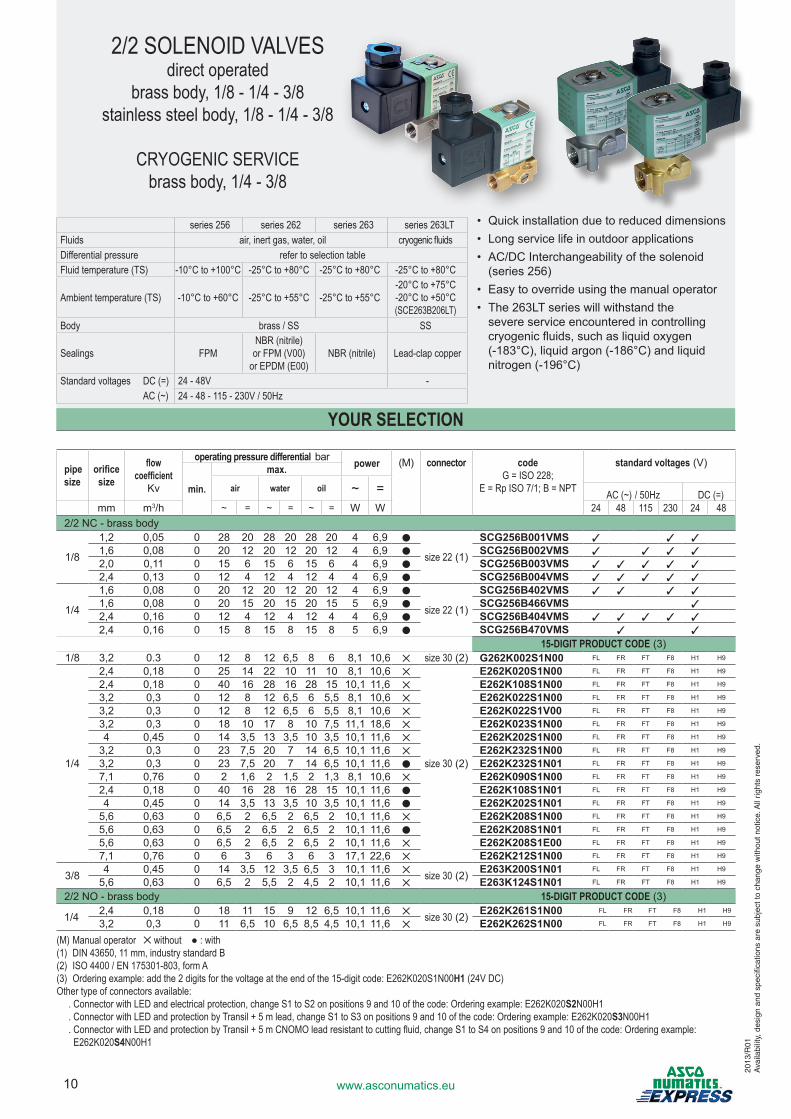
2/2 SOLENOID VALVESdirect operated
brass body, 1/8 - 1/4 - 3/8stainless steel body, 1/8 - 1/4 - 3/8
CRYOGENIC SERVICEbrass body, 1/4 - 3/8
series 256 series 262 series 263 series 263LTFluids air, inert gas, water, oil cryogenic fluidsDifferential pressure refer to selection tableFluid temperature (TS) -10°C to +100°C -25°C to +80°C -25°C to +80°C -25°C to +80°C
Ambient temperature (TS) -10°C to +60°C -25°C to +55°C -25°C to +55°C-20°C to +75°C-20°C to +50°C(SCE263B206LT)
Body brass / SS SS
Sealings FPMNBR (nitrile)
or FPM (V00)or EPDM (E00)
NBR (nitrile) Lead-clap copper
Standard voltages DC (=) 24 - 48V - AC (~) 24 - 48 - 115 - 230V / 50Hz
pipe size
orificesize
flow coefficient
Kv
operating pressure differential bar power (M) connector codeG = ISO 228;
E = Rp ISO 7/1; B = NPT
standard voltages(V)
min.
max.air water oil ~ = AC (~) / 50Hz DC (=)
mm m3/h ~ = ~ = ~ = W W 24 48 115 230 24 482/2 NC - brass body
1/8
1,2 0,05 0 28 20 28 20 28 20 4 6,9 ●
size 22(1)
SCG256B001VMS 3 3 31,6 0,08 0 20 12 20 12 20 12 4 6,9 ● SCG256B002VMS 3 3 3 32,0 0,11 0 15 6 15 6 15 6 4 6,9 ● SCG256B003VMS 3 3 3 3 32,4 0,13 0 12 4 12 4 12 4 4 6,9 ● SCG256B004VMS 3 3 3 3 3
1/4
1,6 0,08 0 20 12 20 12 20 12 4 6,9 ●
size 22(1)
SCG256B402VMS 3 3 3 31,6 0,08 0 20 15 20 15 20 15 5 6,9 ● SCG256B466VMS 32,4 0,16 0 12 4 12 4 12 4 4 6,9 ● SCG256B404VMS 3 3 3 3 32,4 0,16 0 15 8 15 8 15 8 5 6,9 ● SCG256B470VMS 3 3
15-DIGIT PRODUCT CODE(3)1/8 3,2 0.3 0 12 8 12 6,5 8 6 8,1 10,6 ✕ size 30(2) G262K002S1N00 FL FR FT F8 H1 H9
1/4
2,4 0,18 0 25 14 22 10 11 10 8,1 10,6 ✕
size 30(2)
E262K020S1N00 FL FR FT F8 H1 H9
2,4 0,18 0 40 16 28 16 28 15 10,1 11,6 ✕ E262K108S1N00 FL FR FT F8 H1 H9
3,2 0,3 0 12 8 12 6,5 6 5,5 8,1 10,6 ✕ E262K022S1N00 FL FR FT F8 H1 H9
3,2 0,3 0 12 8 12 6,5 6 5,5 8,1 10,6 ✕ E262K022S1V00 FL FR FT F8 H1 H9
3,2 0,3 0 18 10 17 8 10 7,5 11,1 18,6 ✕ E262K023S1N00 FL FR FT F8 H1 H9
4 0,45 0 14 3,5 13 3,5 10 3,5 10,1 11,6 ✕ E262K202S1N00 FL FR FT F8 H1 H9
3,2 0,3 0 23 7,5 20 7 14 6,5 10,1 11,6 ✕ E262K232S1N00 FL FR FT F8 H1 H9
3,2 0,3 0 23 7,5 20 7 14 6,5 10,1 11,6 ● E262K232S1N01 FL FR FT F8 H1 H9
7,1 0,76 0 2 1,6 2 1,5 2 1,3 8,1 10,6 ✕ E262K090S1N00 FL FR FT F8 H1 H9
2,4 0,18 0 40 16 28 16 28 15 10,1 11,6 ● E262K108S1N01 FL FR FT F8 H1 H9
4 0,45 0 14 3,5 13 3,5 10 3,5 10,1 11,6 ● E262K202S1N01 FL FR FT F8 H1 H9
5,6 0,63 0 6,5 2 6,5 2 6,5 2 10,1 11,6 ✕ E262K208S1N00 FL FR FT F8 H1 H9
5,6 0,63 0 6,5 2 6,5 2 6,5 2 10,1 11,6 ● E262K208S1N01 FL FR FT F8 H1 H9
5,6 0,63 0 6,5 2 6,5 2 6,5 2 10,1 11,6 ✕ E262K208S1E00 FL FR FT F8 H1 H9
7,1 0,76 0 6 3 6 3 6 3 17,1 22,6 ✕ E262K212S1N00 FL FR FT F8 H1 H9
3/8 4 0,45 0 14 3,5 12 3,5 6,5 3 10,1 11,6 ✕ size 30(2) E263K200S1N01 FL FR FT F8 H1 H9
5,6 0,63 0 6,5 2 5,5 2 4,5 2 10,1 11,6 ✕ E263K124S1N01 FL FR FT F8 H1 H9
2/2 NO - brass body 15-DIGIT PRODUCT CODE(3)
1/4 2,4 0,18 0 18 11 15 9 12 6,5 10,1 11,6 ✕ size 30(2) E262K261S1N00 FL FR FT F8 H1 H9
3,2 0,3 0 11 6,5 10 6,5 8,5 4,5 10,1 11,6 ✕ E262K262S1N00 FL FR FT F8 H1 H9
(M) Manual operator ✕ without ● : with(1) DIN 43650, 11 mm, industry standard B(2) ISO 4400 / EN 175301-803, form A(3) Ordering example: add the 2 digits for the voltage at the end of the 15-digit code: E262K020S1N00H1 (24V DC)Other type of connectors available: . Connector with LED and electrical protection, change S1 to S2 on positions 9 and 10 of the code: Ordering example: E262K020S2N00H1 . Connector with LED and protection by Transil + 5 m lead, change S1 to S3 on positions 9 and 10 of the code: Ordering example: E262K020S3N00H1 . Connector with LED and protection by Transil + 5 m CNOMO lead resistant to cutting fluid, change S1 to S4 on positions 9 and 10 of the code: Ordering example:
E262K020S4N00H1
• Quick installation due to reduced dimensions• Longservicelifeinoutdoorapplications• AC/DCInterchangeabilityofthesolenoid(series256)
• Easytooverrideusingthemanualoperator• The263LTserieswillwithstandthe severeserviceencounteredincontrollingcryogenicfluids,suchasliquidoxygen(-183°C),liquidargon(-186°C)andliquidnitrogen(-196°C)
YOUR SELECTION
2013
/R01
Ava
ilabi
lity,
des
ign
and
spec
ifica
tions
are
sub
ject
to c
hang
e w
ithou
t not
ice.
All
right
s re
serv
ed.
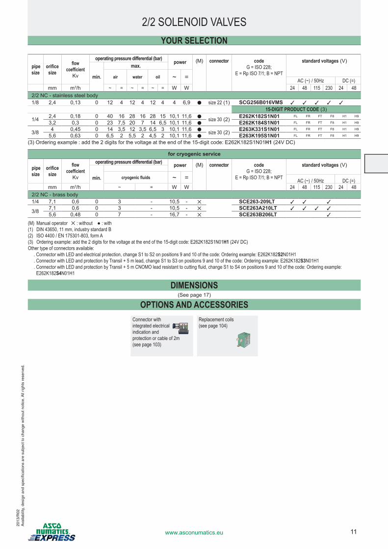
11www.asconumatics.eu
pipe size
orificesize
flow coefficient
Kv
operating pressure differential (bar)power (M) connector code
G = ISO 228; E = Rp ISO 7/1; B = NPT
standard voltages(V)
min.
max.
air water oil ~ = AC (~) / 50Hz DC (=)mm m3/h ~ = ~ = ~ = W W 24 48 115 230 24 48
2/2 NC - stainless steel body1/8 2,4 0,13 0 12 4 12 4 12 4 4 6,9 ● size 22(1) SCG256B016VMS 3 3 3 3 3
15-DIGIT PRODUCT CODE(3)
1/4 2,4 0,18 0 40 16 28 16 28 15 10,1 11,6 ● size 30(2) E262K182S1N01 FL FR FT F8 H1 H9
3,2 0,3 0 23 7,5 20 7 14 6,5 10,1 11,6 ● E262K184S1N01 FL FR FT F8 H1 H9
3/8 4 0,45 0 14 3,5 12 3,5 6,5 3 10,1 11,6 ● size 30(2) E263K331S1N01 FL FR FT F8 H1 H9
5,6 0,63 0 6,5 2 5,5 2 4,5 2 10,1 11,6 ● E263K195S1N01 FL FR FT F8 H1 H9
(3)Orderingexample:addthe2digitsforthevoltageattheendofthe15-digitcode:E262K182S1N01H1(24VDC)
for cryogenic service
pipe size
orificesize
flow coefficient
Kv
operating pressure differential (bar) power (M) connector codeG = ISO 228;
E = Rp ISO 7/1; B = NPT
standard voltages(V)
min. cryogenic fluids ~ = AC (~) / 50Hz DC (=)mm m3/h ~ = W W 24 48 115 230 24 48
2/2 NC - brass body1/4 7,1 0,6 0 3 - 10,5 - ✕ SCE263-209LT 3 3 3
3/8 7,1 0,6 0 3 - 10,5 - ✕ SCE263A210LT 3 3 3 35,6 0,48 0 7 - 16,7 - ✕ SCE263B206LT 3
(M) Manual operator ✕ : without ● : with(1) DIN 43650, 11 mm, industry standard B(2) ISO 4400 / EN 175301-803, form A(3) Ordering example: add the 2 digits for the voltage at the end of the 15-digit code: E262K182S1N01H1 (24V DC)Other type of connectors available: . Connector with LED and electrical protection, change S1 to S2 on positions 9 and 10 of the code: Ordering example: E262K182S2N01H1 . Connector with LED and protection by Transil + 5 m lead, change S1 to S3 on positions 9 and 10 of the code: Ordering example: E262K182S3N01H1 . Connector with LED and protection by Transil + 5 m CNOMO lead resistant to cutting fluid, change S1 to S4 on positions 9 and 10 of the code: Ordering example:
E262K182S4N01H1
DIMENSIONS(Seepage17)
OPTIONS AND ACCESSORIESConnector with integrated electrical indication and protection or cable of 2m (see page 103)
Replacement coils (see page 104)
YOUR SELECTION
2/2 SOLENOID VALVES20
13/R
02A
vaila
bilit
y, d
esig
n an
d sp
ecifi
catio
ns a
re s
ubje
ct to
cha
nge
with
out n
otic
e. A
ll rig
hts
rese
rved
.
12 www.asconumatics.eu
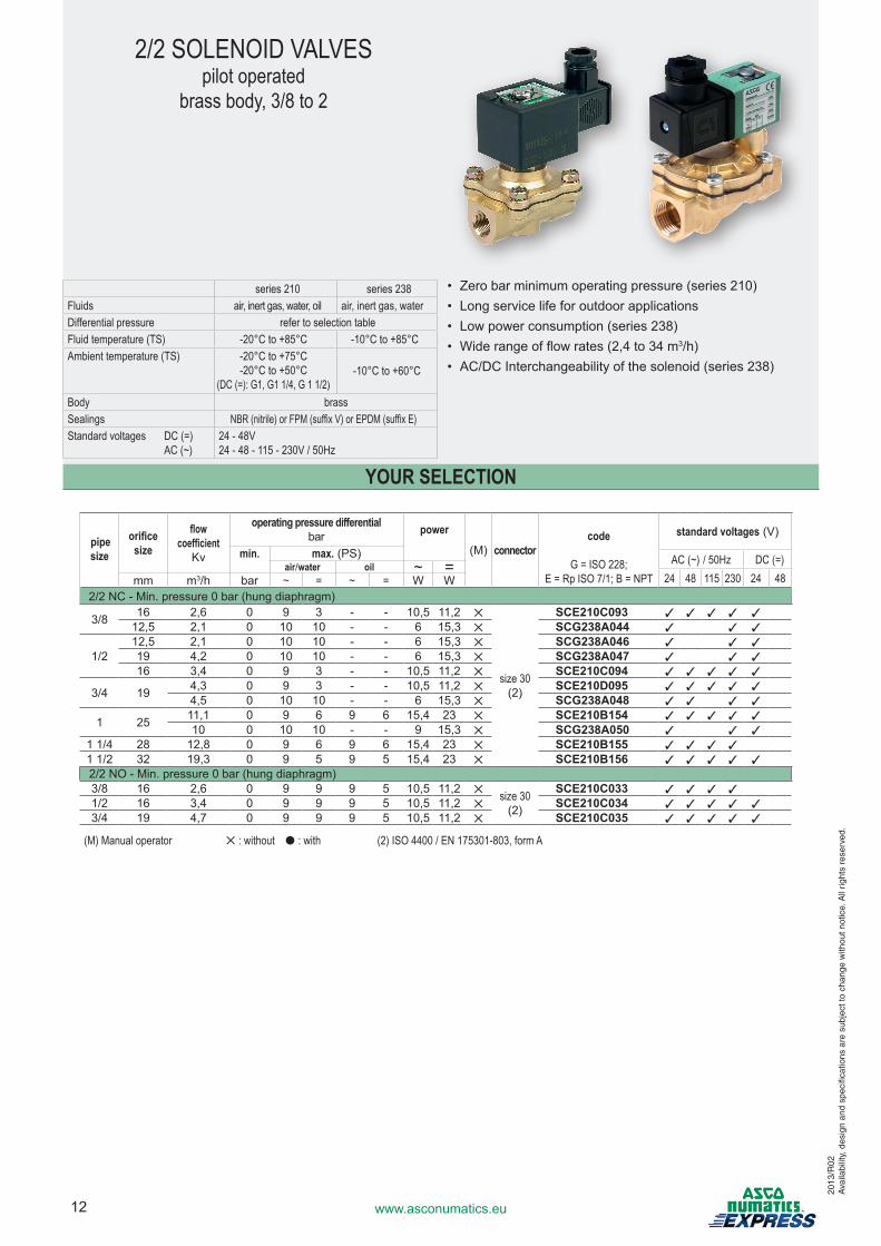
2/2 SOLENOID VALVESpilot operated
brass body, 3/8 to 2
series 210 series 238Fluids air, inert gas, water, oil air, inert gas, waterDifferential pressure refer to selection tableFluid temperature (TS) -20°C to +85°C -10°C to +85°CAmbient temperature (TS) -20°C to +75°C
-20°C to +50°C(DC (=): G1, G1 1/4, G 1 1/2)
-10°C to +60°C
Body brassSealings NBR (nitrile) or FPM (suffix V) or EPDM (suffix E)Standard voltages DC (=) AC (~)
24 - 48V24 - 48 - 115 - 230V / 50Hz
• Zerobarminimumoperatingpressure(series210)• Longservicelifeforoutdoorapplications• Lowpowerconsumption(series238)• Widerangeofflowrates(2,4to34m3/h)• AC/DCInterchangeabilityofthesolenoid(series238)
pipe size
orificesize
flow coefficient
Kv
operating pressure differential bar power
(M) connectorcode
G = ISO 228; E = Rp ISO 7/1; B = NPT
standard voltages(V)
min. max.(PS) AC (~) / 50Hz DC (=)air/water oil ~ =24 48 115 230 24 48mm m3/h bar ~ = ~ = W W
2/2NC-Min.pressure0bar(hungdiaphragm)
3/8 16 2,6 0 9 3 - - 10,5 11,2 ✕
size 30 (2)
SCE210C093 3 3 3 3 312,5 2,1 0 10 10 - - 6 15,3 ✕ SCG238A044 3 3 3
1/212,5 2,1 0 10 10 - - 6 15,3 ✕ SCG238A046 3 3 319 4,2 0 10 10 - - 6 15,3 ✕ SCG238A047 3 3 316 3,4 0 9 3 - - 10,5 11,2 ✕ SCE210C094 3 3 3 3 3
3/4 19 4,3 0 9 3 - - 10,5 11,2 ✕ SCE210D095 3 3 3 3 34,5 0 10 10 - - 6 15,3 ✕ SCG238A048 3 3 3 3
1 25 11,1 0 9 6 9 6 15,4 23 ✕ SCE210B154 3 3 3 3 310 0 10 10 - - 9 15,3 ✕ SCG238A050 3 3 3
1 1/4 28 12,8 0 9 6 9 6 15,4 23 ✕ SCE210B155 3 3 3 31 1/2 32 19,3 0 9 5 9 5 15,4 23 ✕ SCE210B156 3 3 3 3 32/2NO-Min.pressure0bar(hungdiaphragm)3/8 16 2,6 0 9 9 9 5 10,5 11,2 ✕ size 30
(2)
SCE210C033 3 3 3 31/2 16 3,4 0 9 9 9 5 10,5 11,2 ✕ SCE210C034 3 3 3 3 33/4 19 4,7 0 9 9 9 5 10,5 11,2 ✕ SCE210C035 3 3 3 3 3
YOUR SELECTION
(M) Manual operator ✕ : without ● : with (2) ISO 4400 / EN 175301-803, form A20
13/R
02A
vaila
bilit
y, d
esig
n an
d sp
ecifi
catio
ns a
re s
ubje
ct to
cha
nge
with
out n
otic
e. A
ll rig
hts
rese
rved
.
13www.asconumatics.eu
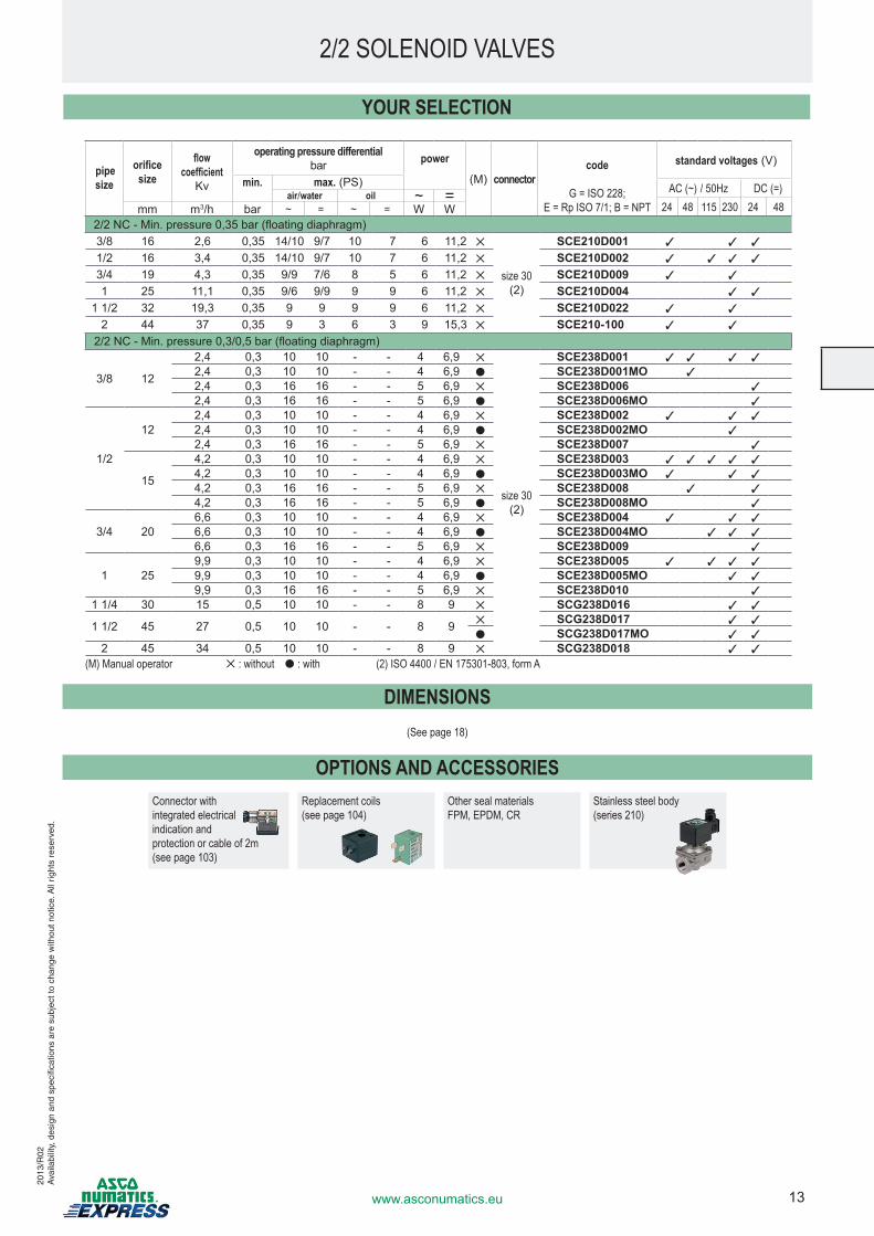
2/2NC-Min.pressure0,35bar(floatingdiaphragm)3/8 16 2,6 0,35 14/10 9/7 10 7 6 11,2 ✕
size 30 (2)
SCE210D001 3 3 3
1/2 16 3,4 0,35 14/10 9/7 10 7 6 11,2 ✕ SCE210D002 3 3 3 3
3/4 19 4,3 0,35 9/9 7/6 8 5 6 11,2 ✕ SCE210D009 3 3
1 25 11,1 0,35 9/6 9/9 9 9 6 11,2 ✕ SCE210D004 3 3
1 1/2 32 19,3 0,35 9 9 9 9 6 11,2 ✕ SCE210D022 3 3
2 44 37 0,35 9 3 6 3 9 15,3 ✕ SCE210-100 3 3
2/2NC-Min.pressure0,3/0,5bar(floatingdiaphragm)
3/8 12
2,4 0,3 10 10 - - 4 6,9 ✕
size 30 (2)
SCE238D001 3 3 3 32,4 0,3 10 10 - - 4 6,9 ● SCE238D001MO 32,4 0,3 16 16 - - 5 6,9 ✕ SCE238D006 32,4 0,3 16 16 - - 5 6,9 ● SCE238D006MO 3
1/2
122,4 0,3 10 10 - - 4 6,9 ✕ SCE238D002 3 3 32,4 0,3 10 10 - - 4 6,9 ● SCE238D002MO 32,4 0,3 16 16 - - 5 6,9 ✕ SCE238D007 3
15
4,2 0,3 10 10 - - 4 6,9 ✕ SCE238D003 3 3 3 3 34,2 0,3 10 10 - - 4 6,9 ● SCE238D003MO 3 3 34,2 0,3 16 16 - - 5 6,9 ✕ SCE238D008 3 34,2 0,3 16 16 - - 5 6,9 ● SCE238D008MO 3
3/4 206,6 0,3 10 10 - - 4 6,9 ✕ SCE238D004 3 3 36,6 0,3 10 10 - - 4 6,9 ● SCE238D004MO 3 3 36,6 0,3 16 16 - - 5 6,9 ✕ SCE238D009 3
1 259,9 0,3 10 10 - - 4 6,9 ✕ SCE238D005 3 3 3 39,9 0,3 10 10 - - 4 6,9 ● SCE238D005MO 3 39,9 0,3 16 16 - - 5 6,9 ✕ SCE238D010 3
1 1/4 30 15 0,5 10 10 - - 8 9 ✕ SCG238D016 3 3
1 1/2 45 27 0,5 10 10 - - 8 9 ✕ SCG238D017 3 3
● SCG238D017MO 3 32 45 34 0,5 10 10 - - 8 9 ✕ SCG238D018 3 3
(M) Manual operator ✕ : without ● : with (2) ISO 4400 / EN 175301-803, form A
DIMENSIONS(See page 18)
OPTIONS AND ACCESSORIESConnector with integrated electrical indication and protection or cable of 2m (see page 103)
Replacement coils (see page 104)
Other seal materialsFPM, EPDM, CR
Stainless steel body(series 210)
pipe size
orificesize
flow coefficient
Kv
operating pressure differentialbar power
(M) connectorcode
G = ISO 228; E = Rp ISO 7/1; B = NPT
standard voltages(V)
min. max.(PS) AC (~) / 50Hz DC (=)air/water oil ~ =24 48 115 230 24 48mm m3/h bar ~ = ~ = W W
YOUR SELECTION
2/2 SOLENOID VALVES20
13/R
02A
vaila
bilit
y, d
esig
n an
d sp
ecifi
catio
ns a
re s
ubje
ct to
cha
nge
with
out n
otic
e. A
ll rig
hts
rese
rved
.
14 www.asconumatics.eu
2013
/R02
Ava
ilabi
lity,
des
ign
and
spec
ifica
tions
are
sub
ject
to c
hang
e w
ithou
t not
ice.
All
right
s re
serv
ed.
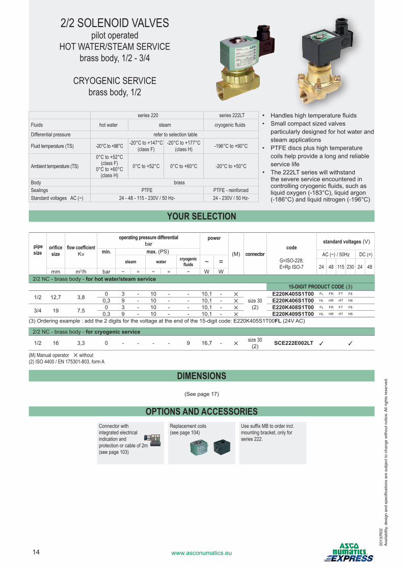
2/2 SOLENOID VALVESpilot operated
HOT WATER/STEAM SERVICEbrass body, 1/2 - 3/4
CRYOGENIC SERVICEbrass body, 1/2
series 220 series 222LT
Fluids hot water steam cryogenic fluids
Differential pressure refer to selection table
Fluid temperature (TS) -20°C to +98°C -20°C to +147°C(class F)
-20°C to +177°C(class H) -196°C to +90°C
Ambient temperature (TS)0°C to +52°C
(class F)0°C to +60°C
(class H)0°C to +52°C 0°C to +60°C -20°C to +50°C
Body brassSealings PTFE PTFE - reinforcedStandard voltages AC (~) 24 - 48 - 115 - 230V / 50 Hz- 24 - 230V / 50 Hz-
• Handleshightemperaturefluids• Smallcompactsizedvalves
particularlydesignedforhotwaterandsteamapplications
• PTFEdiscsplushightemperaturecoilshelpprovidealongandreliableservicelife
• The222LTserieswillwithstandthe severe service encountered in controllingcryogenicfluids,suchasliquidoxygen(-183°C),liquidargon(-186°C)andliquidnitrogen(-196°C)
pipe size
orificesize
flow coefficientKv
operating pressure differential bar
power
(M) connectorcode
G=ISO-228; E=Rp ISO-7
standard voltages(V)
min. max.(PS) AC (~) / 50Hz DC (=)steam water cryogenic
fluids ~ =24 48 115 230 24 48
mm m3/h bar ~ = ~ = ~ W W2/2 NC - brass body - for hot water/steam service
15-DIGIT PRODUCT CODE(3)
1/2 12,7 3,8 0 3 - 10 - - 10,1 - ✕size 30(2)
E220K405S1T00 FL FR FT F8
0,3 9 - 10 - - 10,1 - ✕ E220K406S1T00 HL HR HT H8
3/4 19 7,5 0 3 - 10 - - 10,1 - ✕ E220K408S1T00 FL FR FT F8
0,3 9 - 10 - - 10,1 - ✕ E220K409S1T00 HL HR HT H8
(3)Orderingexample:addthe2digitsforthevoltageattheendofthe15-digitcode:E220K405S1T00FL(24VAC)
2/2 NC - brass body - for cryogenic service
1/2 16 3,3 0 - - - - 9 16,7 - ✕size 30(2) SCE222E002LT 3 3
(M) Manual operator ✕ without (2) ISO 4400 / EN 175301-803, form A
DIMENSIONS
(Seepage17)
OPTIONS AND ACCESSORIESConnector with integrated electrical indication and protection or cable of 2m (see page 103)
Replacement coils (see page 104)
Use suffix MB to order incl. mounting bracket, only for series 222.
YOUR SELECTION
15www.asconumatics.eu
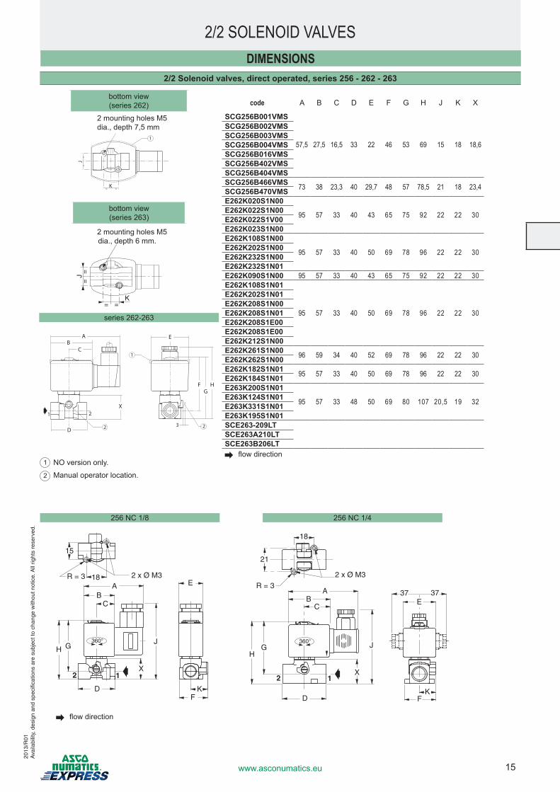
code A B C D E F G H J K X
SCG256B001VMS
57,5 27,5 16,5 33 22 46 53 69 15 18 18,6
SCG256B002VMSSCG256B003VMSSCG256B004VMSSCG256B016VMSSCG256B402VMSSCG256B404VMSSCG256B466VMS 73 38 23,3 40 29,7 48 57 78,5 21 18 23,4SCG256B470VMSE262K020S1N00
95 57 33 40 43 65 75 92 22 22 30E262K022S1N00E262K022S1V00E262K023S1N00E262K108S1N00
95 57 33 40 50 69 78 96 22 22 30E262K202S1N00E262K232S1N00E262K232S1N01E262K090S1N00 95 57 33 40 43 65 75 92 22 22 30E262K108S1N01
95 57 33 40 50 69 78 96 22 22 30
E262K202S1N01E262K208S1N00E262K208S1N01E262K208S1E00E262K208S1E00E262K212S1N00E262K261S1N00 96 59 34 40 52 69 78 96 22 22 30E262K262S1N00E262K182S1N01 95 57 33 40 50 69 78 96 22 22 30E262K184S1N01E263K200S1N01
95 57 33 48 50 69 80 107 20,5 19 32E263K124S1N01E263K331S1N01E263K195S1N01SCE263-209LTSCE263A210LTSCE263B206LT flowdirection
DIMENSIONS
2/2 SOLENOID VALVES
2/2 Solenoid valves, direct operated, series 256 - 262 - 263
2mountingholesM5dia.,depth6mm.
bottomview(series262)
256 NC 1/8
bottomview(series263)
15
18R = 3
X
2 x Ø M3A E
B
H G
DF
K
J
C
2 1
360°
21
18
R = 3A 37 37
B
HG
D FK
J
X
C
2 1
2 x Ø M3
360°
E
256 NC 1/4
HFG
AB
C
X21
E
D3
1
2 2
==
J
= =K
= =K
==
J
1
2mountingholesM5dia.,depth7,5mm
series 262-263
1 NO version only.
2 Manualoperatorlocation.
flowdirection
2013
/R01
Ava
ilabi
lity,
des
ign
and
spec
ifica
tions
are
sub
ject
to c
hang
e w
ithou
t not
ice.
All
right
s re
serv
ed.
16 www.asconumatics.eu
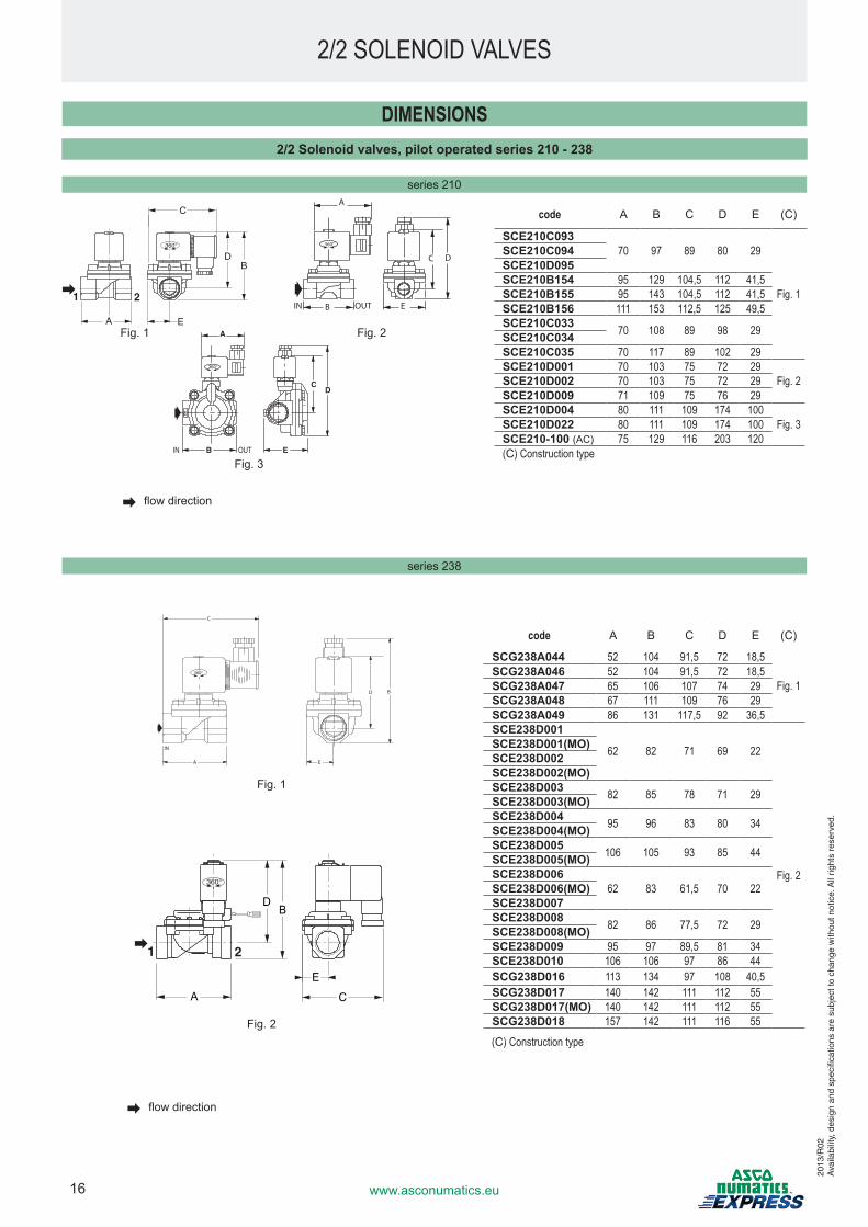
code A B C D E (C)
SCE210C09370 97 89 80 29
Fig. 1
SCE210C094SCE210D095SCE210B154 95 129 104,5 112 41,5SCE210B155 95 143 104,5 112 41,5SCE210B156 111 153 112,5 125 49,5SCE210C033 70 108 89 98 29SCE210C034SCE210C035 70 117 89 102 29SCE210D001 70 103 75 72 29
Fig. 2SCE210D002 70 103 75 72 29SCE210D009 71 109 75 76 29SCE210D004 80 111 109 174 100
Fig. 3SCE210D022 80 111 109 174 100SCE210-100 (AC) 75 129 116 203 120(C) Construction type
code A B C D E (C)
SCG238A044 52 104 91,5 72 18,5
Fig. 1SCG238A046 52 104 91,5 72 18,5SCG238A047 65 106 107 74 29SCG238A048 67 111 109 76 29SCG238A049 86 131 117,5 92 36,5SCE238D001
62 82 71 69 22
Fig. 2
SCE238D001(MO)SCE238D002SCE238D002(MO)SCE238D003 82 85 78 71 29SCE238D003(MO)SCE238D004 95 96 83 80 34SCE238D004(MO)SCE238D005 106 105 93 85 44SCE238D005(MO)SCE238D006
62 83 61,5 70 22SCE238D006(MO)SCE238D007SCE238D008 82 86 77,5 72 29SCE238D008(MO)SCE238D009 95 97 89,5 81 34SCE238D010 106 106 97 86 44SCG238D016 113 134 97 108 40,5SCG238D017 140 142 111 112 55SCG238D017(MO) 140 142 111 112 55SCG238D018 157 142 111 116 55
series 238
flowdirection
DIMENSIONS2/2 Solenoid valves, pilot operated series 210 - 238
2/2 SOLENOID VALVES
series 210
flowdirection
Fig.1 A
B OUTIN E
CD
360°
Fig.3
A
B E
C D
OUTIN
360°
Fig.2
(C) Construction type
E
DB
CA
360°
1 2
Fig.2
IN
360°
C
A E
BD
Fig.1
2013
/R02
Ava
ilabi
lity,
des
ign
and
spec
ifica
tions
are
sub
ject
to c
hang
e w
ithou
t not
ice.
All
right
s re
serv
ed.
360°
1 2
C
DB
EA
17www.asconumatics.eu
2/2 SOLENOID VALVES20
13/R
02A
vaila
bilit
y, d
esig
n an
d sp
ecifi
catio
ns a
re s
ubje
ct to
cha
nge
with
out n
otic
e. A
ll rig
hts
rese
rved
.
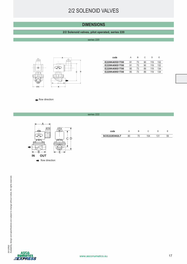
series 220
code A B C D E
E220K405S1T00 91 73 90 119 132E220K406S1T00 91 73 90 119 132E220K408S1T00 95 73 89 119 134E220K409S1T00 95 73 89 119 134
DIMENSIONS2/2 Solenoid valves, pilot operated, series 220
series 222
code A B C D E
SCE222E002LT 80 70 104 131 59
flowdirection
flowdirection
360°
A
B E
C D
IN OUT
360°
A
C D
BØ E
18 www.asconumatics.eu
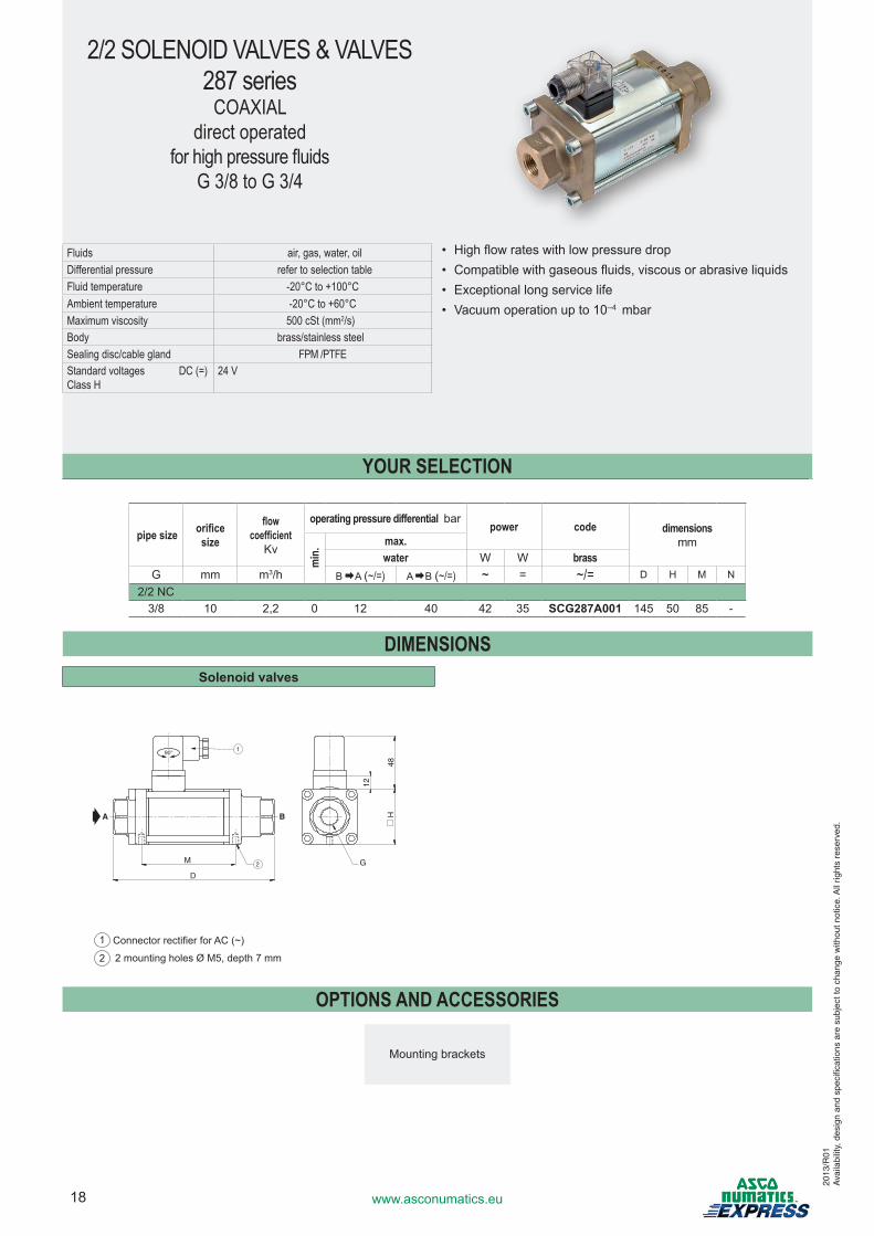
2/2 SOLENOID VALVES & VALVES287 series
COAXIALdirect operated
for high pressure fluidsG 3/8 to G 3/4
pipe size orificesize
flow coefficient
Kv
operating pressure differential barpower code dimensions
mm
min
. max.water W W brass
G mm m3/h B A(~/=) A B(~/=) ~ = ~/= D H M N
2/2 NC3/8 10 2,2 0 12 40 42 35 SCG287A001 145 50 85 -
DIMENSIONSSolenoid valves
48
D
G
A B H
12
M
90°
2
1
1 ConnectorrectifierforAC(~)2 2mountingholesØM5,depth7mm
OPTIONS AND ACCESSORIES
Mountingbrackets
Fluids air, gas, water, oilDifferential pressure refer to selection tableFluid temperature -20°C to +100°CAmbient temperature -20°C to +60°CMaximum viscosity 500 cSt (mm2/s)Body brass/stainless steelSealing disc/cable gland FPM /PTFEStandard voltages DC (=) Class H
24 V
• Highflowrateswithlowpressuredrop• Compatiblewithgaseousfluids, viscous or abrasive liquids• Exceptionallongservicelife• Vacuumoperationupto10--4 mbar
YOUR SELECTION
2013
/R01
Ava
ilabi
lity,
des
ign
and
spec
ifica
tions
are
sub
ject
to c
hang
e w
ithou
t not
ice.
All
right
s re
serv
ed.
19www.asconumatics.eu
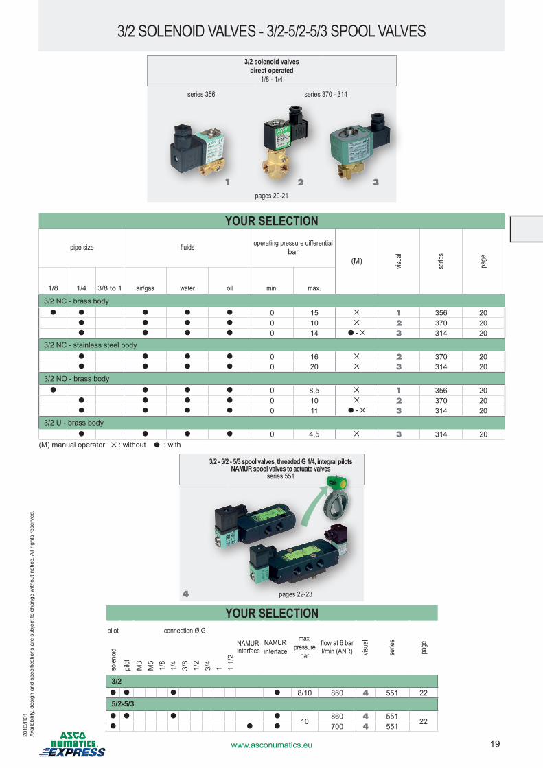
3/2 solenoid valvesdirect operated
1/8 - 1/4
series 356 series 370 - 314
pages 20-21
YOUR SELECTION
pipe size fluids operating pressure differentialbar
(M)
visua
l
serie
s
page
1/8 1/4 3/8 to 1 air/gas water oil min. max.
3/2 NC - brass body● ● ● ● ● 0 15 ✕ 1 356 20
● ● ● ● 0 10 ✕ 2 370 20● ● ● ● 0 14 ● - ✕ 3 314 20
3/2 NC - stainless steel body● ● ● ● 0 16 ✕ 2 370 20● ● ● ● 0 20 ✕ 3 314 20
3/2 NO - brass body● ● ● ● 0 8,5 ✕ 1 356 20
● ● ● ● 0 10 ✕ 2 370 20● ● ● ● 0 11 ● - ✕ 3 314 20
3/2 U - brass body● ● ● ● 0 4,5 ✕ 3 314 20
3/2 SOLENOID VALVES - 3/2-5/2-5/3 SPOOL VALVES
1 32
(M)manualoperator✕ :without●:with
3/2 - 5/2 - 5/3 spool valves, threaded G 1/4, integral pilotsNAMUR spool valves to actuate valves
series 551
4 pages 22-23
YOUR SELECTIONpilot connection Ø G
NAMUR interface
NAMUR interface
max. pressure
bar
flow at 6 barl/min (ANR) vis
ual
serie
s
page
solen
oid
pilot
M3
M5
1/8
1/4
3/8
1/2
3/4
1 1 1/
2
3/2● ● ● ● 8/10 860 4 551 225/2-5/3● ● ● ●
10860 4 551
22● ● ● 700 4 551
2013
/R01
Ava
ilabi
lity,
des
ign
and
spec
ifica
tions
are
sub
ject
to c
hang
e w
ithou
t not
ice.
All
right
s re
serv
ed.
20 www.asconumatics.eu
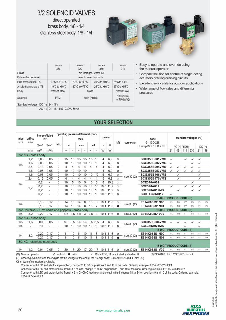
3/2 SOLENOID VALVESdirect operated
brass body, 1/8 - 1/4stainless steel body, 1/8 - 1/4
series 356
series 320
series 370
series314
Fluids air, inert gas, water, oil Differential pressure refer to selection tableFluid temperature (TS) -10°C to +100°C -20°C to +90°C -25°C to +80°C -25°C to +90°CAmbient temperature (TS) -10°C to +60°C -20°C to +75°C -25°C to +60°C -25°C to +55°CBody brass/st. steel brass brass/st. steel
Sealings FPM NBR (nitrile) NBR (nitrile)or FPM (V00)
Standard voltages DC (=) 24 - 48V AC (~) 24 - 48 - 115 - 230V / 50Hz
• Easytooperateandoverrideusing themanualoperator
• Compactsolutionforcontrolofsingle-actingactuatorsorfilling/drainingcircuits
• Excellentservicelifeforoutdoorapplications• Widerangeofflowratesanddifferentialpressures
pipe size
orificesize
flow coefficientKv
operating pressure differential (bar)power
(M) connectorcode
G = ISO 228; E = Rp ISO 7/1; B = NPT
standard voltages(V)
min.max.
2➙1 3➙1 air water oil ~ = AC (~) / 50Hz DC (=)mm m3/h m3/h ~ = ~ = ~ = W W 24 48 115 230 24 48
3/2 NC - brass body
1/8
1,2 0,05 0,05 0 15 15 15 15 15 15 4 6,9 ✕
size 30(2)
SCG356B001VMS 3 3 3 3
1,6 0,08 0,05 0 10 10 10 10 10 10 4 6,9 ✕ SCG356B002VMS 3 3 3
2,4 0,13 0,05 0 4 4 4 4 4 4 4 6,9 ✕ SCG356B004VMS 3 3 3 3 3
1,6 0,08 0,05 0 10 10 10 10 - - 4 6,9 ✕ SCG356B053VMS 3 3 3 3 3
1/4
1,6 0,08 0,05 0 10 10 10 10 10 10 5 6,9 ✕ SCG356B466VMS 3 3
2,4 0,16 0,05 0 4 4 4 4 4 4 5 6,9 ✕ SCG356B470VMS 3 3
2,7
0,2 - 0 10 5 10 5 10 5 8 10,8 ✕ SCE370A002 3
0,2 - 0 10 10 10 10 10 10 10,5 11,2 ✕ SCE370A017 3 3 3 3
0,2 - 0 10 10 10 10 10 10 10,5 11,2 ✕ SCE370A017MS 3 3 3
0,2 - 0 10 10 10 10 10 10 10,5 11,2 ✕ SCHTE370A017 3
15-DIGIT PRODUCT CODE(3)
1/4 0,13 0,17 0 14 10 14 8 13 6 10,1 11,6 ✕ size 30(2) E314K035S1N00 FL FR FT F8 F1 F9
0,13 0,17 0 14 10 14 8 13 7 10,1 11,6 ● E314K035S1N01 FL FR FT F8 F1 F9
3/2Universal-FPMsealsandpoppets-brassbody 15-DIGIT PRODUCT CODE(3)1/4 3,2 0,22 0,17 0 4,5 3,5 4,5 3 2,5 3 10,1 11,6 ✕ size 30(2) E314K008S1V00 FL FR FT F8 F1 F9
3/2 NO - brass body1/8 1,6 0,096 0,05 0 8,5 8,5 8,5 8,5 8,5 8,5 4 6,9 ✕ size 30(2) SCG356B006VMS 3 3 3 3 3
1/4 2 0,11 - 0 10 10 10 10 10 10 10,5 11,2 ✕ SCE370A021MS 3 3
15-DIGIT PRODUCT CODE(3)
1/4 3,2 0,22 0,17 0 11 10 11 10 11 8 10,1 11,6 ✕ size 30(2) E314K054S1N00 FL FR FT F8 F1 F9
0,22 0,17 0 11 10 11 10 11 8 10,1 11,6 ● E314K054S1N01 FL FR FT F8 F1 F9
3/2 NC - stainless steel body15-DIGIT PRODUCT CODE(3)
1/4 1,2 0,04 0,05 0 20 17 20 17 20 17 10,1 11,6 ✕ size 30(2) E314K068S1V00 FL FR FT F8 F1 F9
(M) Manual operator ✕ : without ● : with (1) DIN 43650, 11 mm, industry standard B (2) ISO 4400 / EN 175301-803, form A(3) Ordering example: add the 2 digits for the voltage at the end of the 15-digit code: E314K035S1N00F1 (24V DC)Other type of connectors available: . Connector with LED and electrical protection, change S1 to S2 on positions 9 and 10 of the code: Ordering example: E314K035S2N00F1 . Connector with LED and protection by Transil + 5 m lead, change S1 to S3 on positions 9 and 10 of the code: Ordering example: E314K035S3N00F1 . Connector with LED and protection by Transil + 5 m CNOMO lead resistant to cutting fluid, change S1 to S4 on positions 9 and 10 of the code: Ordering example:
E314K035S4N00F1
YOUR SELECTION
2013
/R02
Ava
ilabi
lity,
des
ign
and
spec
ifica
tions
are
sub
ject
to c
hang
e w
ithou
t not
ice.
All
right
s re
serv
ed.
21www.asconumatics.eu
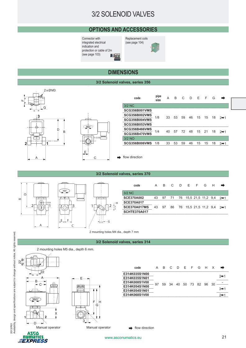
DIMENSIONS3/2 Solenoid valves, series 356
3/2 SOLENOID VALVES
code pipe size A B C D E F G
3/2 NCSCG356B001VMS
1/8 33 53 59 46 15 15 18 2 1SCG356B002VMSSCG356B004VMSSCG356B053VMSSCG356B466VMS
1/4 40 57 72 48 15 21 18 2 1SCG356B470VMS3/2 NOSCG356B006VMS 1/8 33 53 59 46 15 15 18 3 1
A
DB
C
E
==15
12
3
360°
= =
==
F
G
2 x Ø M3
flowdirection
flowdirection
3/2 Solenoid valves, series 370
code A B C D E F G H
3/2 NCSCE370A002 43 97 71 76 15,5 21,5 11,2 9,4 2 1SCE370A017
43 97 86 76 15,5 21,5 11,2 9,4 2 1SCE370A017MSSCHTE370A017
B
D
AE F
12 213 3
= =
==
G
H
360˚
C
2mountingholesM4dia.,depth7mm
22
HFG
A
C
1 2
D
= =
==
22
X
E
360°
B
3
2mountingholesM5dia.,depth6mm.
Manualoperator Manualoperator
code A B C D E F G H X
E314K035S1N00
97 59 34 40 50 73 82 96 30
2 1E314K035S1N01E314K008S1V00 -E314K054S1N00
3 1E314K054S1N01E314K068S1V00 2 1
3/2 Solenoid valves, series 314
2013
/R01
Ava
ilabi
lity,
des
ign
and
spec
ifica
tions
are
sub
ject
to c
hang
e w
ithou
t not
ice.
All
right
s re
serv
ed.
OPTIONS AND ACCESSORIESConnector with integrated electrical indication and protection or cable of 2m (see page 103)
Replacement coils (see page 104)
22 www.asconumatics.eu
Namur integral pilot versions for valve pilotingcode(1) connector
standard voltages (V)power AC (~) / 50Hz DC (=)~ =
24 48 115 230 24 48VA W (M)
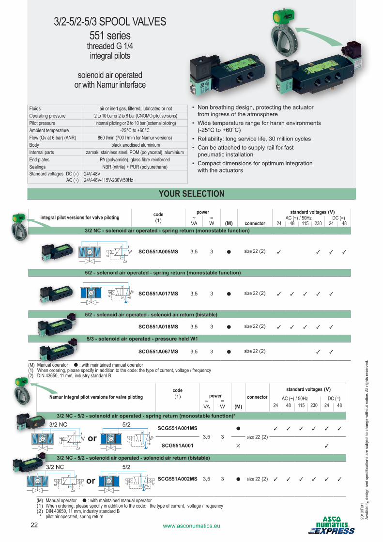
3/2 NC - 5/2 - solenoid air operated - spring return (monostable function)*
SCG551A001MS3,5 3
●
size 22(2)3 3 3 3 3 3
SCG551A001 ✕ 3
3/2 NC - 5/2 - solenoid air operated - solenoid air return (bistable)
SCG551A002MS 3,5 3 ● size 22(2) 3 3 3 3 3 3
(M) Manual operator ● : with maintained manual operator(1) When ordering, please specify in addition to the code: the type of current, voltage / frequency(2) DIN 43650, 11 mm, industry standard B * pilot air operated, spring return
or42
1
312
42
1
5312
3/2 NC 5/2
or42
1
312 10
42
1
5312 10
3/2 NC 5/2
integral pilot versions for valve piloting code(1)
power standard voltages (V)~ = AC (~) / 50Hz DC (=)VA W (M) connector 24 48 115 230 24 48
3/2 NC - solenoid air operated - spring return (monostable function)
SCG551A005MS 3,5 3 ● size 22(2) 3 3 3 3
5/2 - solenoid air operated - spring return (monostable function)
SCG551A017MS 3,5 3 ● size 22(2) 3 3 3 3 3
5/2 - solenoid air operated - solenoid air return (bistable)
SCG551A018MS 3,5 3 ● size 22(2) 3 3 3 3 3
5/3 - solenoid air operated - pressure held W1
SCG551A067MS 3,5 3 ● size 22(2) 3 3
(M) Manual operator ● : with maintained manual operator(1) When ordering, please specify in addition to the code: the type of current, voltage / frequency(2) DIN 43650, 11 mm, industry standard B
42
1
312
42
1
5312
3/2-5/2-5/3 SPOOL VALVES551 series
threaded G 1/4integral pilots
solenoid air operated or with Namur interface
Fluids air or inert gas, filtered, lubricated or notOperating pressure 2 to 10 bar or 2 to 8 bar (CNOMO pilot versions)Pilot pressure internal piloting or 2 to 10 bar (external piloting)Ambient temperature -25°C to +60°CFlow (Qv at 6 bar) (ANR) 860 l/min (700 l /min for Namur versions)Body black anodised aluminiumInternal parts zamak, stainless steel, POM (polyacetal), aluminiumEnd plates PA (polyamide), glass-fibre reinforcedSealings NBR (nitrile) + PUR (polyurethane)Standard voltages DC (=) 24V-48V
24V-48V-115V-230V/50Hz AC (~)
• Nonbreathingdesign,protectingtheactuator fromingressoftheatmosphere
• Widetemperaturerangeforharshenvironments (-25°Cto+60°C)
• Reliability:longservicelife,30millioncycles• Canbeattachedtosupplyrailforfast pneumaticinstallation
• Compactdimensionsforoptimumintegration withtheactuators
2013
/R01
Ava
ilabi
lity,
des
ign
and
spec
ifica
tions
are
sub
ject
to c
hang
e w
ithou
t not
ice.
All
right
s re
serv
ed.
YOUR SELECTION
23www.asconumatics.eu
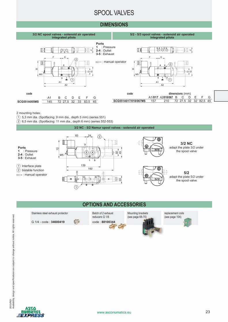
SPOOL VALVES
OPTIONS AND ACCESSORIESStainless steel exhaust protector Batch of 2 exhaust
reducers G 1/8Mounting brackets(see page 68-70)
replacement coils(see page 104)
G 1/4 - code : 34600419 code : 88100344
DIMENSIONS3/2 NC spool valves - solenoid air operated
integrated pilots5/2 - 5/3 spool valves - solenoid air operated
integrated pilots
123
3 1
2
2F E
B
D GC
A1
M5
A2
1
15 4 2 3
4
5 3
2
1
2
1
F E
B
D GC
A1A2
M5
codeA1 B C D E F G
SCG551A005MS 145 72 27,5 32 33 83,5 45
code dimensions(mm)A1/017 A2/018/067 B C D E F G
SCG551A017/018/067MS 157 210 72 27,5 32 32 82,5 45
2mountingholes:1 5,3mmdia.(Spotfacing:9mmdia.,depth5mm)(series551)2 6,5mmdia.(Spotfacing:11mmdia.,depth6mm)(series552-553)
Ports1 : Pressure2-4 : Outlet3-5:Exhaust
:manualoperator
3/2 NC - 5/2 Namur spool valves - solenoid air operated
3
1 5
3 51
42
2
1
83 24
72
32 4533
139
M5
192
3/2
3/2 NCadapttheplate3/2under
thespoolvalve
5/2
5/2adapttheplate5/2under
thespoolvalve :manualoperator
1 Interfaceplate2 bistablefunction
Ports1 : Pressure2-4 : Outlet3-5:Exhaust
2013
/R01
Ava
ilabi
lity,
des
ign
and
spec
ifica
tions
are
sub
ject
to c
hang
e w
ithou
t not
ice.
All
right
s re
serv
ed.
24 www.asconumatics.eu
2013
/R02
Ava
ilabi
lity,
des
ign
and
spec
ifica
tions
are
sub
ject
to c
hang
e w
ithou
t not
ice.
All
right
s re
serv
ed.
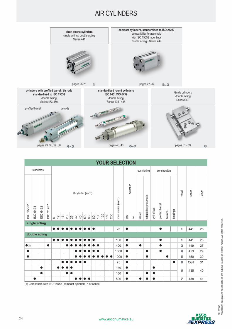
AIR CYLINDERS
short stroke cylinders single acting / double acting
Series 441
compact cylinders, standardised to ISO 21287 compatibility for assembly with ISO 15552 mountings double acting - Series 449
pages 25-26 pages 27-28
cylinders with profiled barrel / tie rods standardised to ISO 15552
double acting Series 453-450
standardised round cylinders ISO 6431/ISO 6432
double acting Series 435 / 438
Guide cylindersdouble acting Series CGT
profiled barrel tie rods
pages 29..30, 32..38 pages 40..43 pages 31 - 39
YOUR SELECTIONstandards
Ø cylinder (mm)
max.
strok
e (m
m)
detec
tion
cushioning construction
visua
l
serie
s
page
ISO
155
52
ISO
643
1
ISO
643
2
ISO
212
87
elasti
c
adjus
table
pneu
matic
cylin
drica
l
profi
led ba
rrel
tie ro
ds
bear
ings
8 12 16 20 25 32 40 50 63 80 100
125
160
200
yes
no
single acting
● ● ● ● ● ● ● ● ● ● 25 ● ● 1 441 25
double acting
● ● ● ● ● ● ● ● ● ● 100 ● ● 1 441 25
●(1) ● ● ● ● ● ● ● ● ● 400 ● ● ● 2 449 27
● ● ● ● ● ● ● 1000 ● ● ● 4 453 29
● ● ● ● ● ● ● ● ● ● 1000 ● ● ● 5 450 30
● ● ● ● ● ● 75 ● ● 8 CGT 31
● ● ● ● ● 160 ● ●6 435 40
● ● ● 160 ● ● ●
● ● ● ● ● 500 ● ● ● ● 7 438 41(1) Compatible with ISO 15552 (compact cylinders, 449 series)
1 2-3
4-5 6-7 8
25www.asconumatics.eu
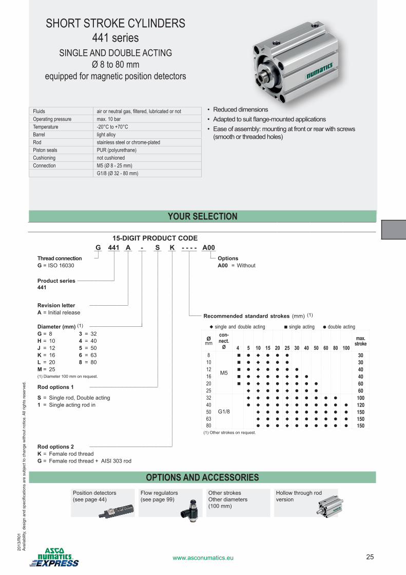
15-DIGIT PRODUCT CODEG 441 A - S K - - - - A00
Thread connection Options G = ISO 16030 A00 = Without
Product series441
Revision letterA = Initial release Recommended standard strokes (mm) (1)
Diameter (mm) (1) u single and double acting ■ single acting ● double actingG = 8 3 = 32
Ømm
con-nect.
Ømax.
strokeH = 10 4 = 40J = 12 5 = 50 4 5 10 15 20 25 30 40 50 60 80 100K = 16 6 = 63 8
M5
■ ● u ● ● ● 30L = 20 8 = 80 10 ■ ● u ● ● ● 30M = 25 12 ■ ● u ● ● ● ● 40(1) Diameter 100 mm on request. 16 ■ ● u ● ● u ● ● 40
Rod options 1 20 ■ ● u ● ● u ● ● ● 6025 u u ● ● u ● ● ● 60
S = Single rod, Double acting 32
G1/8
u u ● ● u ● ● ● ● ● 1001 = Single acting rod in 40 ● u ● ● u ● ● ● ● ● ● 120
50 u ● ● u ● ● ● ● ● ● 15063 u ● ● u ● ● ● ● ● ● 15080 ● ● ● u ● ● ● ● ● ● 150
(1) Other strokes on request.
Rod options 2K = Female rod threadG = Female rod thread + AISI 303 rod
OPTIONS AND ACCESSORIESPosition detectors (see page 44)
Flow regulators (see page 99)
Other strokesOther diameters(100 mm)
Hollow through rod version
SHORT STROKE CYLINDERS441 series
SINGLE AND DOUBLE ACTINGØ 8 to 80 mm
equipped for magnetic position detectors
Fluids air or neutral gas, filtered, lubricated or notOperating pressure max. 10 barTemperature -20°C to +70°CBarrel light alloyRod stainless steel or chrome-platedPiston seals PUR (polyurethane)Cushioning not cushionedConnection M5 (Ø 8 - 25 mm)
G1/8 (Ø 32 - 80 mm)
• Reduced dimensions• �Adapted�to�suit�flange-mounted�applications• Ease of assembly: mounting at front or rear with screws
(smooth or threaded holes)
YOUR SELECTION
2013
/R01
Ava
ilabi
lity,
des
ign
and
spec
ifica
tions
are
sub
ject
to c
hang
e w
ithou
t not
ice.
All
right
s re
serv
ed.
26 www.asconumatics.eu
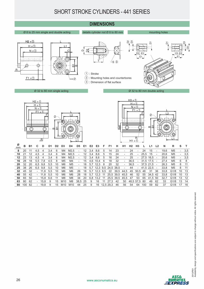
DIMENSIONS
SHORT STROKE CYLINDERS - 441 SERIES
Ø 8 to 25 mm single and double acting details cylinder rod Ø 8 to 80 mm mounting holes
Ø 32 to 80 mm single acting Ø 32 to 80 mm double acting
Ømm B B1 C D D1 D2 D3 D4 D5 E1 E2 E3 F F1 H H1 H2 H3 L L1 L2 N R S T
8 20 11 4,5 4 3,4 6 M4 M2,5 - 12 3,4 8,6 5 14 23 - 24 - 24 15 - 19,6 M5 - 3,510 21 12 4,5 4 3,4 6 M4 M2,5 - 12 3,4 8,6 5 15 24 - 25 - 25,5 15 - 20,6 M5 - 3,512 23 13 4,5 4 3,4 6 M4 M2,5 - 12 3,4 8,6 5 16 24 - 25 - 27,5 16,5 - 20,6 M5 - 3,516 28 18 5,5 7,8 4,5 8 M5 M4 - 15 4,6 10,4 6 18 32 - 36,5 - 31,5 17,5 - 27,4 M5 6 820 32 20 6,5 9,8 5,5 10 M6 M5 - 18 5,7 12,3 8 20 32 - 36,5 - 37,5 21,5 - 26,3 M5 8 1125 38 26 6,5 9,8 5,5 10 M6 M5 - 18 5,7 12,3 9,5 24,5 38,5 - 44 - 41,5 22,5 - 33,8 M5 8 1132 45 32 - 11,8 5,5 10 M6 M6 26 18 5,7 12,3 9,5 22 39,5 44,5 45 50,5 48 31 36 33,8 G1/8 10 1340 55 42 - 11,8 5,5 10 M6 M6 28 18 5,7 12,3 11 25,5 39,5 45,5 46 52 55 34,5 42 33,8 G1/8 10 1350 65 50 - 15,8 6,6 11 M8 M8 34 20 6,8 13,2 11 25,5 39,5 45,5 47 53 65 41,5 50 32,7 G1/8 13 1263 80 62 - 15,8 9 15 M10 M8 38,5 25 9 16 11 27,3 42 50 48,5 57,5 80 49 62 33 G1/8 13 1480 100 82 - 19,8 9 15 M10 M10 44 25 9 16 12,5 29,3 46 56 54 64 100 59 82 37 G1/8 17 16
3S
•
T
D4
H2 + 1
H + 1
N + 1
F1 + 1
H2 + 1
R
L
L1
C
B1 B
D2
E1E2 E3
D1D2
D3
•
•
•
E1E2E3
D1
D2
D3
H2 + 1H + 1N + 1
FF1 + 1
R L1
B
LL2
B1
2
R
F
H3 + 1H + 1N + 1F1 + 1
H1 + 1L1
B
LL2
B1
2
1 : Stroke2 : Mounting holes and counterbores3 : Dimension�of�flat�surface
2013
/R01
Ava
ilabi
lity,
des
ign
and
spec
ifica
tions
are
sub
ject
to c
hang
e w
ithou
t not
ice.
All
right
s re
serv
ed.
27www.asconumatics.eu
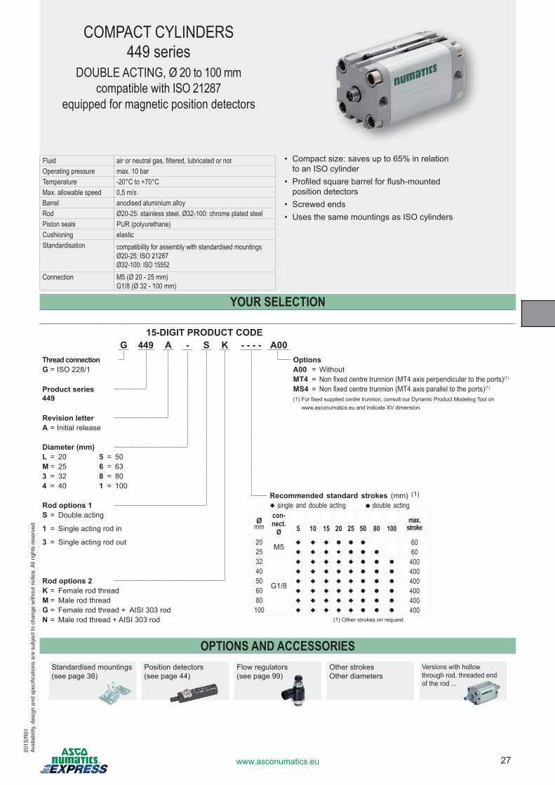
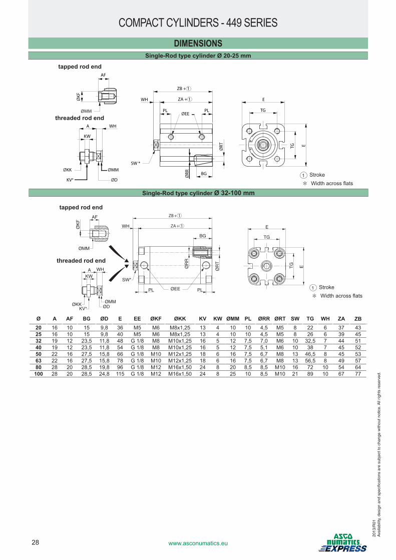
COMPACT CYLINDERS449 series
DOUBLE ACTING, Ø 20 to 100 mmcompatible with ISO 21287
equipped for magnetic position detectors
Fluid air or neutral gas, filtered, lubricated or notOperating pressure max. 10 barTemperature -20°C to +70°CMax. allowable speed 0,5 m/s Barrel anodised aluminium alloyRod Ø20-25: stainless steel, Ø32-100: chrome plated steelPiston seals PUR (polyurethane)Cushioning elasticStandardisation compatibility for assembly with standardised mountings
Ø20-25: ISO 21287Ø32-100: ISO 15552
Connection M5 (Ø 20 - 25 mm)G1/8 (Ø 32 - 100 mm)
15-DIGIT PRODUCT CODEG 449 A - S K - - - - A00
Thread connection OptionsG = ISO 228/1 A00 = Without
MT4 = Non�fixed�centre�trunnion�(MT4�axis�perpendicular�to�the�ports)(1)
Product series449
MS4 = Non�fixed�centre�trunnion�(MT4�axis�parallel�to�the�ports)(1)
(1)��For�fixed�supplied�centre�trunnion,�consult�our�Dynamic�Product�Modeling�Tool�on�www.asconumatics.eu and indicate XV dimension.
Revision letterA = Initial release
Diameter (mm)L = 20 5 = 50M = 25 6 = 633 = 32 8 = 804 = 40 1 = 100
Recommended standard strokes (mm) (1)
Rod options 1 u single and double acting ● double actingS = Double acting
Ømm
con-nect.
Ømax.
stroke1 = Single acting rod in 5 10 15 20 25 50 80 100
3 = Single acting rod out 20 M5 u u u ● ● ● 6025 u u u u ● ● ● 6032
G1/8
u u u u u ● ● ● 40040 u u u u u ● ● ● 400
Rod options 2 50 u u u u u ● ● ● 400K = Female rod thread 60 u u u u u ● ● ● 400M = Male rod thread 80 u u u u u ● ● ● 400G = Female rod thread + AISI 303 rod 100 u u u u u ● ● ● 400N = Male rod thread + AISI 303 rod (1) Other strokes on request.
YOUR SELECTION
OPTIONS AND ACCESSORIESStandardised mountings(see page 36)
Position detectors (see page 44)
Flow regulators (see page 99)
Other strokesOther diameters
Versions with hollow through rod, threaded end of the rod ...
2013
/R01
Ava
ilabi
lity,
des
ign
and
spec
ifica
tions
are
sub
ject
to c
hang
e w
ithou
t not
ice.
All
right
s re
serv
ed.
•� �Compact�size:�saves�up�to�65%�in�relation to an ISO cylinder
•� �Profiled�square�barrel�for�flush-mounted position detectors
•� �Screwed�ends•� �Uses�the�same�mountings�as�ISO�cylinders
28 www.asconumatics.eu
DIMENSIONSSingle-Rod type cylinder Ø 20-25 mm
COMPACT CYLINDERS - 449 SERIES
WH
BG
SW*
PL PLØEE
ØR
R
ØR
T AF
ØMM
ØK
F
A WH
KW
ØKKKV*
ØMMØD
E
TG
ETG
WH
KW
ØKK
AFØ
KF
ØMM
A WH
KV*
ØMM
ØD
ZB + 1
ZA + 1WH
PL PLØEE
ØRT
ØRR
SW *
BG
E
TG
TG E
Ø A AF BG ØD E EE ØKF ØKK KV KW ØMM PL ØRR ØRT SW TG WH ZA ZB20 16 10 15 9,8 36 M5 M6 M8x1,25 13 4 10 10 4,5 M5 8 22 6 37 4325 16 10 15 9,8 40 M5 M6 M8x1,25 13 4 10 10 4,5 M5 8 26 6 39 4532 19 12 23,5 11,8 48 G 1/8 M8 M10x1,25 16 5 12 7,5 7,0 M6 10 32,5 7 44 5140 19 12 23,5 11,8 54 G 1/8 M8 M10x1,25 16 5 12 7,5 5,1 M6 10 38 7 45 5250 22 16 27,5 15,8 66 G 1/8 M10 M12x1,25 18 6 16 7,5 6,7 M8 13 46,5 8 45 5363 22 16 27,5 15,8 78 G 1/8 M10 M12x1,25 18 6 16 7,5 6,7 M8 13 56,5 8 49 5780 28 20 28,5 19,8 96 G 1/8 M12 M16x1,50 24 8 20 8,5 8,5 M10 16 72 10 54 64
100 28 20 28,5 24,8 115 G 1/8 M12 M16x1,50 24 8 25 10 8,5 M10 21 89 10 67 77
tapped rod end
threaded rod end
tapped rod end
threaded rod end
1 Stroke ✻� ��Width�across�flats
1 Stroke ✻� ��Width�across�flats
Single-Rod type cylinder Ø 32-100 mm
2013
/R01
Ava
ilabi
lity,
des
ign
and
spec
ifica
tions
are
sub
ject
to c
hang
e w
ithou
t not
ice.
All
right
s re
serv
ed.
29www.asconumatics.eu
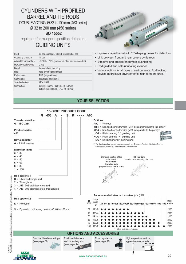
CYLINDERS WITH PROFILED BARREL AND TIE RODS
DOUBLE ACTING, Ø 32 to 100 mm (453 series)Ø 32 to 200 mm (450 series)
ISO 15552equipped for magnetic position detectors
GUIDING UNITS• Square�shaped�barrel�with�“T”-shape�grooves�for�detectors• Link between front and rear covers by tie rods• Effective and precise pneumatic cushioning• �Rod�guided�and�self-lubricating�cylinder• Various options for all types of environments: Rod locking
device, aggressive environments, high temperatures…
15-DIGIT PRODUCT CODEG 453 A - S K - - - - A00
Thread connection OptionsG = ISO 228/1 A00 = Without
MT4 = Non�fixed�centre�trunnion�(MT4�axis�perpendicular�to�the�ports)(1)
Product series MS4 = Non�fixed�centre�trunnion�(MT4�axis�parallel�to�the�ports)(1)
453 UCG�=�Plain�bearing�"U"�guiding�unitHCG = Plain bearing "H" guiding unit
Revision letter HBG = Ball bearing "H" guiding unitA = Initial release (1)���For�fixed�supplied�centre�trunnion,�consult�our�Dynamic�Product�Modeling�Tool�on
www.asconumatics.eu and indicate XV dimension.
Diameter (mm)3 = 324 = 405 = 506 = 638 = 801 = 100
Rod options 1S = Chromed Single rod2 = Through rod3 = AISI 303 stainless steel rod4 = AISI 303 stainless steel through rod
Recommended standard strokes (mm) (1)
Rod options 2Ø
mmcon-nect.
Ømax.
strokeK = No option 25 50 80 100 125 160 200 250 320 400 500 630 700 800 900 1000 1500
5� =� Dynamic�rod-locking�device�-�Ø�40�to�100�mm 32 G1/8 ● ● ● ● ● ● ● ● 2000
40 G1/4 ● ● ● ● ● ● ● ● ● ● ● ● 200050 G1/4 ● ● ● ● ● ● ● ● ● ● ● ● ● 200063 G3/8 ● ● ● ● ● ● ● ● ● ● ● ● ● ● ● 200080 G3/8 ● ● ● ● ● ● ● ● ● ● ● ● ● ● ● ● 2000
100 G1/2 ● ● ● ● ● ● ● ● ● ● ● ● ● ● ● ● ● 2000(1) Other strokes on request.
YOUR SELECTION
OPTIONS AND ACCESSORIESStandardised mountings(see page 36)
Position detectors and mounting kits (see page 44)
Flow regulators (see page 99)
High temperature versions, aggressive environments...
Standard position of the centre trunnionMT4 option:
trunnion axis perpendicular to the ports
MS4 option:trunnion�axis�parallel�to�the�ports
2013
/R03
Ava
ilabi
lity,
des
ign
and
spec
ifica
tions
are
sub
ject
to c
hang
e w
ithou
t not
ice.
All
right
s re
serv
ed.
Fluid air or neutral gas, filtered, lubricated or notOperating pressure 10 bar Allowable temperature -20°C to +70°C (contact us if this limit is exceeded)Max. allowable speed 2 m/s Barrel treated aluminium alloyRod hard chrome plated steelPiston seals PUR (polyurethane)Cushioning adjustable pneumaticStandardisation ISO 15552Connection G1/8 (Ø 32mm) - G1/4 (Ø40 - 50mm)
G3/8 (Ø63 - 80mm) - G1/2 (Ø 100mm)
30 www.asconumatics.eu
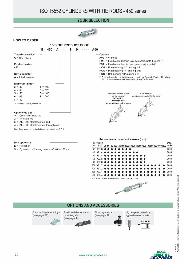
HOW TO ORDER15-DIGIT PRODUCT CODE
G 450 A - S K - - - - A00Thread connection OptionsG = ISO 16030 A00 = Without
FMT = Fixed�centre�trunnion�(axis�perpendicular�to�the�ports)(3)
Product series FST = Fixed�centre�trunnion�(axis�parallel�to�the�ports)(3)
450 UCG�=�Plain�bearing�"U"�guiding�unitHCG = Plain bearing "H" guiding unit
Revision letter HBG = Ball bearing "H" guiding unitA = Initial release (3)��For�fixed�supplied�centre�trunnion,�consult�our�Dynamic�Product�Modeling�
Tool on www.asconumatics.eu and indicate XV dimension.
Diameter (mm) (1)
3 = 32 1 = 1004 = 40 P = 1255 = 50 Q = 1606 = 63 R = 2008 = 80(1) 250 mm/ 320 mm, contact us
Options de tige 1S = Chromed single rod2 = Through rod3 = AISI 303 stainless steel rod4 = AISI 303 stainless steel through rodStainless steel rod nuts delivered with options 3 & 4.
Recommended standard strokes (mm) (5)
Rod options 2 Ømm
connect.Ø (G)
max. strokeK = No option 25 50 80 10012516020025032040050060070080090010001500
5� =� �Dynamic�rod-locking�device�-�Ø�40�to�100�mm 32 G1/8 ● ● ● ● ● ● ● ● 200040 G1/4 ● ● ● ● ● ● ● ● ● ● 200050 G1/4 ● ● ● ● ● ● ● ● ● ● ● ● 200063 G3/8 ● ● ● ● ● ● ● ● ● ● ● ● 200080 G3/8 ● ● ● ● ● ● ● ● ● ● ● ● 2000
100 G1/2 ● ● ● ● ● ● ● ● ● ● ● ● ● ● ● ● ● 2000125 G1/2 ● ● ● ● ● ● ● ● ● ● ● ● ● ● ● ● ● 2000160 G3/4 ● ● ● ● ● ● ● ● ● ● ● ● ● ● ● ● ● 2000200 G3/4 ● ● ● ● ● ● ● ● ● ● ● ● ● ● ● ● ● 2000(5) Other strokes on request. / Min. stroke: 5 mm
2013
/R03
Ava
ilabi
lity,
des
ign
and
spec
ifica
tions
are
sub
ject
to c
hang
e w
ithou
t not
ice.
All
right
s re
serv
ed.
ISO 15552 CYLINDERS WITH TIE RODS - 450 seriesYOUR SELECTION
OPTIONS AND ACCESSORIESStandardised mountings(see page 36)
Position detectors and mounting kits (see page 44)
Flow regulators (see page 99)
High temperature versions, aggressive environments...
Standard position of the centre trunnionFMT option : trunnion axis
perpendicular to the ports
FST option :trunnion�axis�parallel�to�the�ports
31www.asconumatics.eu
2013
/R02
Ava
ilabi
lity,
des
ign
and
spec
ifica
tions
are
sub
ject
to c
hang
e w
ithou
t not
ice.
All
right
s re
serv
ed.
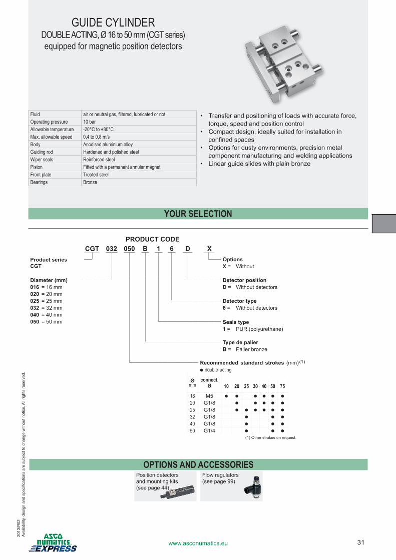
GUIDE CYLINDERDOUBLE ACTING, Ø 16 to 50 mm (CGT series)equipped for magnetic position detectors
• Transfer and positioning of loads with accurate force, torque, speed and position control
• Compact design, ideally suited for installation in confined�spaces
• Options for dusty environments, precision metal component manufacturing and welding applications
• �Linear�guide�slides�with�plain�bronze
YOUR SELECTION
Fluid air or neutral gas, filtered, lubricated or notOperating pressure 10 barAllowable temperature -20°C to +80°CMax. allowable speed 0,4 to 0,8 m/s Body Anodised aluminium alloyGuiding rod Hardened and polished steelWiper seals Reinforced steelPiston Fitted with a permanent annular magnetFront plate Treated steelBearings Bronze
PRODUCT CODECGT 032 050 B 1 6 D X
Product seriesCGT
OptionsX = Without
Diameter (mm) Detector position016 = 16 mm D = Without detectors020 = 20 mm025 = 25 mm Detector type032 = 32 mm 6 = Without detectors040 = 40 mm050 = 50 mm Seals type
1�=� PUR�(polyurethane)
Type de palierB�=� Palier�bronze
Recommended standard strokes (mm)(1)
● double acting
Ømm
connect.Ø 10 20 25 30 40 50 75
16 M5 ● ● ● ● ● ●
20 G1/8 ● ● ● ● ●
25 G1/8 ● ● ● ● ● ●
32 G1/8 ● ● ●
40 G1/8 ● ● ●
50 G1/4 ● ● ●
(1) Other strokes on request.
OPTIONS AND ACCESSORIESPosition detectors and mounting kits (see page 44)
Flow regulators (see page 99)
32 www.asconumatics.eu
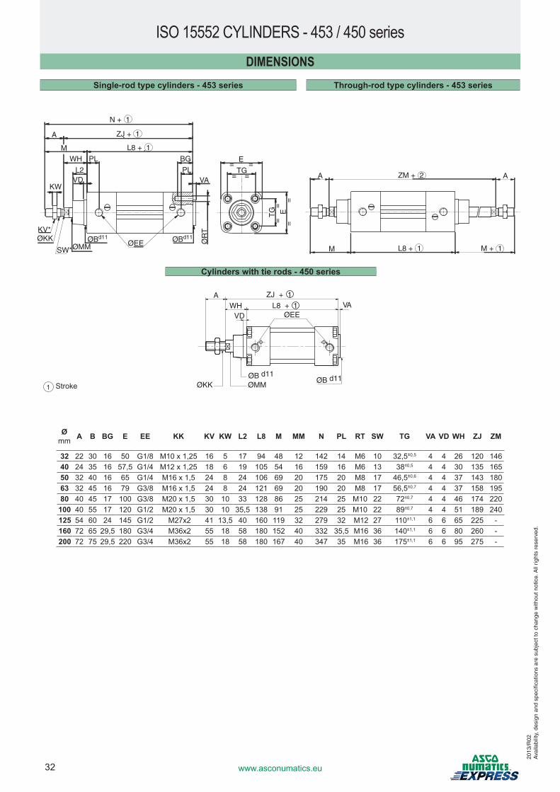
DIMENSIONSSingle-rod type cylinders - 453 series Through-rod type cylinders - 453 series
ISO 15552 CYLINDERS - 453 / 450 series
1 Stroke
N + 1
ZJ + 1
L8 + 1
ØR
T
TG
=
=
=
=E
ØEE
A
MWH
L2VD
PL E= =
= =TG
BG
PLVA
ØBd11 ØBd11
ØMMSW*
KV*ØKK
KW
A AZM + 2
L8 + 1M M + 1
Cylinders with tie rods - 450 series
ØB d11
VAØEEVD
WHA
L8 + 1
ZJ + 1
ØB d11
ØMMØKK
Ømm A B BG E EE KK KV KW L2 L8 M MM N PL RT SW TG VA VD WH ZJ ZM
32 22 30 16 50 G1/8 M10�x�1,25 16 5 17 94 48 12 142 14 M6 10 32,5±0,5 4 4 26 120 14640 24 35 16 57,5 G1/4 M12�x�1,25 18 6 19 105 54 16 159 16 M6 13 38±0,5 4 4 30 135 16550 32 40 16 65 G1/4 M16�x�1,5 24 8 24 106 69 20 175 20 M8 17 46,5±0,6 4 4 37 143 18063 32 45 16 79 G3/8 M16�x�1,5 24 8 24 121 69 20 190 20 M8 17 56,5±0,7 4 4 37 158 19580 40 45 17 100 G3/8 M20�x�1,5 30 10 33 128 86 25 214 25 M10 22 72±0,7 4 4 46 174 220
100 40 55 17 120 G1/2 M20�x�1,5 30 10 35,5 138 91 25 229 25 M10 22 89±0,7 4 4 51 189 240125 54 60 24 145 G1/2 M27x2 41 13,5 40 160 119 32 279 32 M12 27 110±1,1 6 6 65 225 -160 72 65 29,5 180 G3/4 M36x2 55 18 58 180 152 40 332 35,5 M16 36 140±1,1 6 6 80 260 -200 72 75 29,5 220 G3/4 M36x2 55 18 58 180 167 40 347 35 M16 36 175±1,1 6 6 95 275 -
2013
/R02
Ava
ilabi
lity,
des
ign
and
spec
ifica
tions
are
sub
ject
to c
hang
e w
ithou
t not
ice.
All
right
s re
serv
ed.
33www.asconumatics.eu
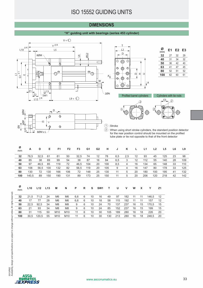
DIMENSIONS“H” guiding unit with bearings (series 453 cylinder)
E2
E3 2
V + 1
Y + K
L5
W
8ØM
L10 + K
G1
+
1L1 E
Z1Z2 SW1
L13
L12 +
K L9 + 1
2ØN
T
LL6 Ø
G2
4ØM
4ØP
ØX
J2 J 8ØM x L
L2D
D
D
A
A
D H U
=
=
= =
=
=
E1
2
Ømm A D E F1 F2 F3 G1 G2 H J K L L1 L2 L5 L6 L9
32 78,5 32,5 61 81 50 32,5 74 12 78 6,5 2,5 12 93 45 125 23 9840 85 38 69 99 54 38 87 16 84 6,5 3 12 112 55 140 28 10950 97 46,5 85 119 72 46,5 104 20 100 8,5 4 16 134 65 148 33 11063 106 56,5 100 132 82 56,5 119 20 105 9 4 16 147 80 178 33 12580 130 72 130 166 106 72 148 25 130 11 5 20 180 100 195 41 132
100 140,5 89 150 190 131 89 173 25 150 11 5 20 206 120 218 42 142
Ømm L10 L12 L13 M N P R S SW1 T U V W X Y Z1
32 21,5 71,5 24 M6 M6 6,6 6 10 16 49 97 182 11 11 146,5 1240 17 77 28 M6 M6 6,6 6 10 18 58 115 192 11 11 157 1250 22,5 92,5 34 M8 M8 9 6 10 24 70 137 237 16 15 170,5 1563 21 93 34 M8 M8 9 6 10 24 85 152 237 16 15 199 1580 31 115 50 M10 M10 11 6 10 30 105 189 280 16 18 226 20
100 30,5 120,5 55 M10 M10 11 6 10 30 130 213 280 16 18 248,5 20
Ø(mm) E1 E2 E332 27 32 2940 31 34 3250 36 42 4063 41 47 4580 52 51 52
100 62 60 61
Profiled barrel cylinders Cylinders with tie rods
1 : Stroke2 : When using short stroke cylinders, the standard position detector
for�the�rear�position�control�should�be�mounted�on�the�profiled�tube plate or tie rod opposite to that of the front detector
ISO 15552 GUIDING UNITS20
13/R
02A
vaila
bilit
y, d
esig
n an
d sp
ecifi
catio
ns a
re s
ubje
ct to
cha
nge
with
out n
otic
e. A
ll rig
hts
rese
rved
.
34 www.asconumatics.eu
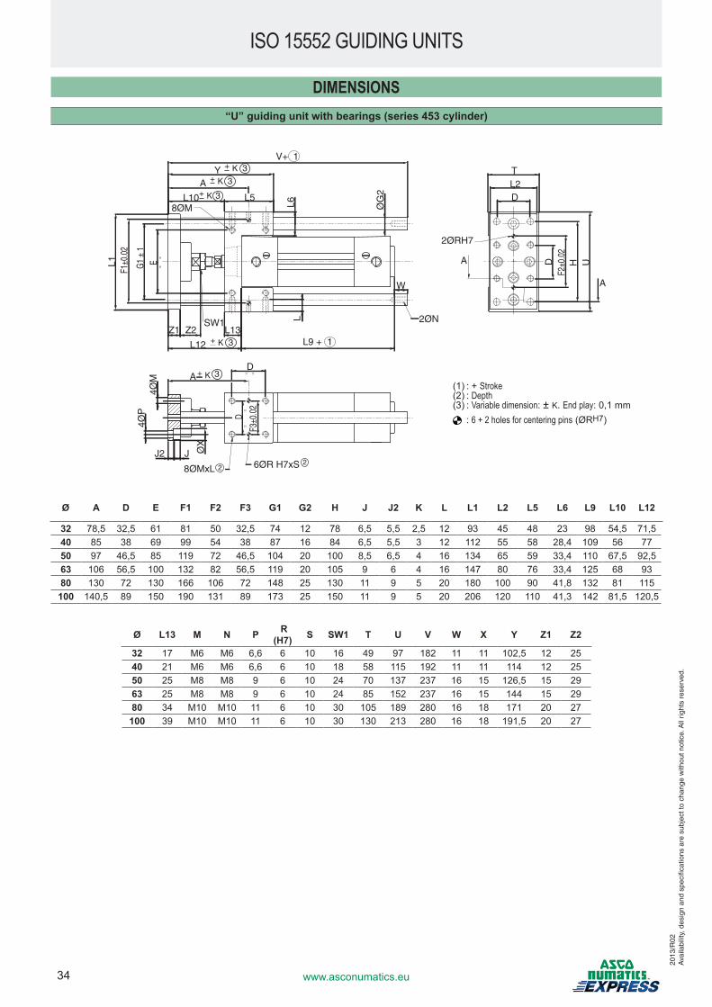
DIMENSIONS“U” guiding unit with bearings (series 453 cylinder)
=
=
G1
± 1
E =
=
= =
F1±
0.02
F3±
0.02
D
V + 1Y + K
A + K
L5
L6
L10+ K
L1
Z2Z1SW1
L12 + K
L13
L
L9 + 1
ØG
2
W
8ØM
2ØN
A + K D
J2 J
8ØMxL 6ØR H7xS
4ØM
4ØP
ØX
2ØRH7
A
TL2D
D F
2±0.
02H U
A
22
3
3
3
3
3
Ø A D E F1 F2 F3 G1 G2 H J J2 K L L1 L2 L5 L6 L9 L10 L12
32 78,5 32,5 61 81 50 32,5 74 12 78 6,5 5,5 2,5 12 93 45 48 23 98 54,5 71,540 85 38 69 99 54 38 87 16 84 6,5 5,5 3 12 112 55 58 28,4 109 56 7750 97 46,5 85 119 72 46,5 104 20 100 8,5 6,5 4 16 134 65 59 33,4 110 67,5 92,563 106 56,5 100 132 82 56,5 119 20 105 9 6 4 16 147 80 76 33,4 125 68 9380 130 72 130 166 106 72 148 25 130 11 9 5 20 180 100 90 41,8 132 81 115
100 140,5 89 150 190 131 89 173 25 150 11 9 5 20 206 120 110 41,3 142 81,5 120,5
Ø L13 M N P R (H7) S SW1 T U V W X Y Z1 Z2
32 17 M6 M6 6,6 6 10 16 49 97 182 11 11 102,5 12 2540 21 M6 M6 6,6 6 10 18 58 115 192 11 11 114 12 2550 25 M8 M8 9 6 10 24 70 137 237 16 15 126,5 15 2963 25 M8 M8 9 6 10 24 85 152 237 16 15 144 15 2980 34 M10 M10 11 6 10 30 105 189 280 16 18 171 20 27
100 39 M10 M10 11 6 10 30 130 213 280 16 18 191,5 20 27
(1) : + Stroke(2) : Depth(3) : Variable dimension: ± K. End play: 0,1 mm
: 6 + 2 holes for centering pins (ØRH7)
ISO 15552 GUIDING UNITS
2013
/R02
Ava
ilabi
lity,
des
ign
and
spec
ifica
tions
are
sub
ject
to c
hang
e w
ithou
t not
ice.
All
right
s re
serv
ed.
35www.asconumatics.eu
2013
/R02
Ava
ilabi
lity,
des
ign
and
spec
ifica
tions
are
sub
ject
to c
hang
e w
ithou
t not
ice.
All
right
s re
serv
ed.
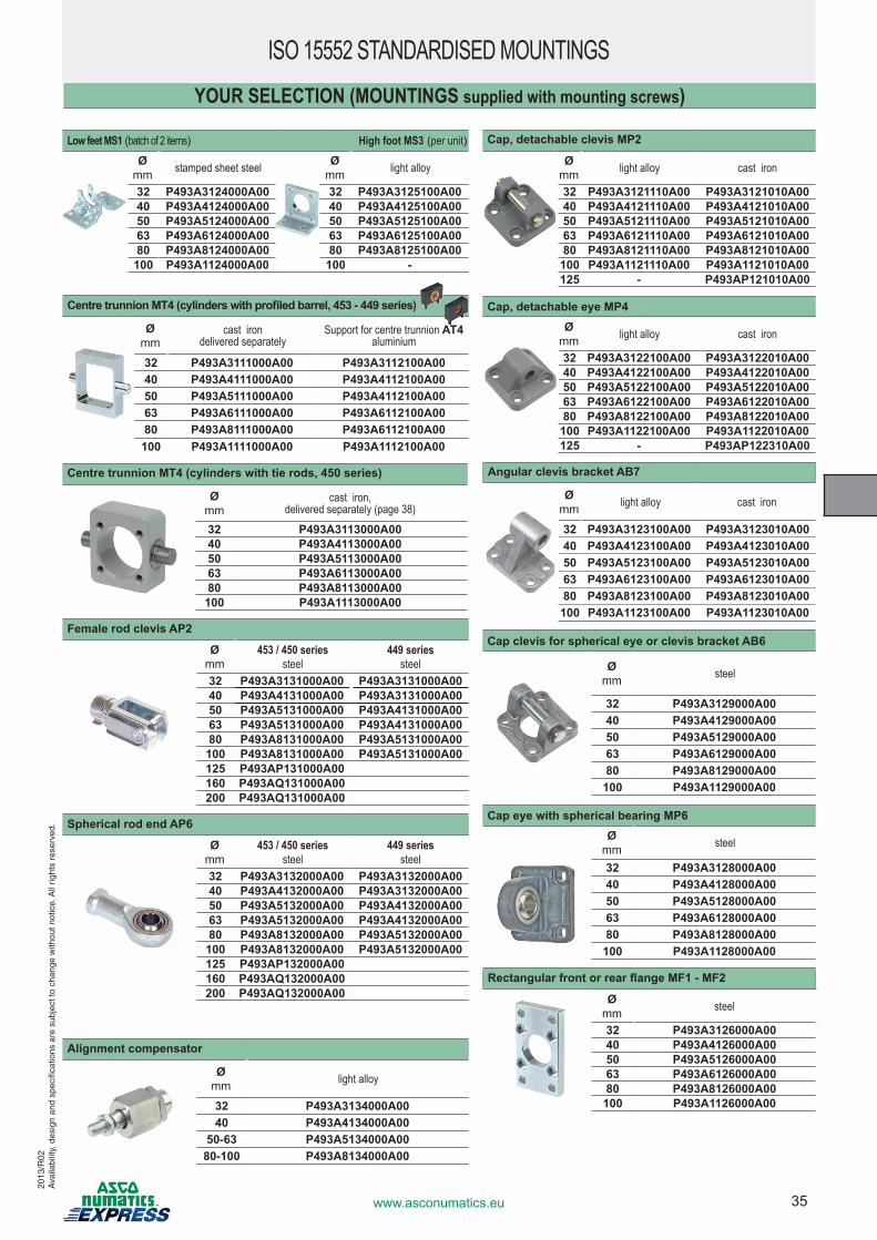
Low feet MS1 (batch of 2 items) High foot MS3 (per unit)Ø
mm stamped sheet steel Ømm light alloy
32 P493A3124000A00 32 P493A3125100A0040 P493A4124000A00 40 P493A4125100A0050 P493A5124000A00 50 P493A5125100A0063 P493A6124000A00 63 P493A6125100A0080 P493A8124000A00 80 P493A8125100A00
100 P493A1124000A00 100 -
Centre trunnion MT4 (cylinders with profiled barrel, 453 - 449 series)
Ømm
cast iron delivered separately
Support for centre trunnion AT4aluminium
32 P493A3111000A00 P493A3112100A0040 P493A4111000A00 P493A4112100A0050 P493A5111000A00 P493A4112100A0063 P493A6111000A00 P493A6112100A0080 P493A8111000A00 P493A6112100A00
100 P493A1111000A00 P493A1112100A00
Centre trunnion MT4 (cylinders with tie rods, 450 series)
Ømm
cast iron, delivered separately (page 38)
32 P493A3113000A0040 P493A4113000A0050 P493A5113000A0063 P493A6113000A0080 P493A8113000A00
100 P493A1113000A00
Female rod clevis AP2
Ømm
453 / 450 seriessteel
449 seriessteel
32 P493A3131000A00 P493A3131000A0040 P493A4131000A00 P493A3131000A0050 P493A5131000A00 P493A4131000A0063 P493A5131000A00 P493A4131000A0080 P493A8131000A00 P493A5131000A00
100 P493A8131000A00 P493A5131000A00125 P493AP131000A00160 P493AQ131000A00200 P493AQ131000A00
Spherical rod end AP6
Ømm
453 / 450 seriessteel
449 seriessteel
32 P493A3132000A00 P493A3132000A0040 P493A4132000A00 P493A3132000A0050 P493A5132000A00 P493A4132000A0063 P493A5132000A00 P493A4132000A0080 P493A8132000A00 P493A5132000A00
100 P493A8132000A00 P493A5132000A00125 P493AP132000A00160 P493AQ132000A00200 P493AQ132000A00
ISO 15552 STANDARDISED MOUNTINGS
Cap, detachable clevis MP2
Ømm light alloy cast iron
32 P493A3121110A00 P493A3121010A0040 P493A4121110A00 P493A4121010A0050 P493A5121110A00 P493A5121010A0063 P493A6121110A00 P493A6121010A0080 P493A8121110A00 P493A8121010A00
100 P493A1121110A00 P493A1121010A00125 - P493AP121010A00
Cap, detachable eye MP4 Ø
mm light alloy cast iron
32 P493A3122100A00 P493A3122010A0040 P493A4122100A00 P493A4122010A0050 P493A5122100A00 P493A5122010A0063 P493A6122100A00 P493A6122010A0080 P493A8122100A00 P493A8122010A00
100 P493A1122100A00 P493A1122010A00125 - P493AP122310A00
Angular clevis bracket AB7
Ømm light alloy cast iron
32 P493A3123100A00 P493A3123010A0040 P493A4123100A00 P493A4123010A0050 P493A5123100A00 P493A5123010A0063 P493A6123100A00 P493A6123010A0080 P493A8123100A00 P493A8123010A00
100 P493A1123100A00 P493A1123010A00
Cap clevis for spherical eye or clevis bracket AB6
Ømm steel
32 P493A3129000A0040 P493A4129000A0050 P493A5129000A0063 P493A6129000A0080 P493A8129000A00
100 P493A1129000A00
Cap eye with spherical bearing MP6Ø
mm steel
32 P493A3128000A0040 P493A4128000A0050 P493A5128000A0063 P493A6128000A0080 P493A8128000A00
100 P493A1128000A00
Rectangular front or rear flange MF1 - MF2
Ømm steel
32 P493A3126000A0040 P493A4126000A0050 P493A5126000A0063 P493A6126000A0080 P493A8126000A00
100 P493A1126000A00
YOUR SELECTION (MOUNTINGS supplied with mounting screws)
Alignment compensator
Ømm light alloy
32 P493A3134000A0040 P493A4134000A00
50-63 P493A5134000A0080-100 P493A8134000A00
36 www.asconumatics.eu
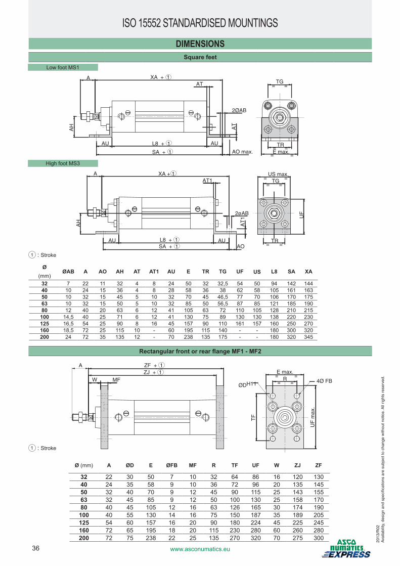
ISO 15552 STANDARDISED MOUNTINGSDIMENSIONS
Square feet
Ø(mm)
ØAB A AO AH AT AT1 AU E TR TG UF US L8 SA XA
32 7 22 11 32 4 8 24 50 32 32,5 54 50 94 142 14440 10 24 15 36 4 8 28 58 36 38 62 58 105 161 16350 10 32 15 45 5 10 32 70 45 46,5 77 70 106 170 17563 10 32 15 50 5 10 32 85 50 56,5 87 85 121 185 19080 12 40 20 63 6 12 41 105 63 72 110 105 128 210 215
100 14,5 40 25 71 6 12 41 130 75 89 130 130 138 220 230125 16,5 54 25 90 8 16 45 157 90 110 161 157 160 250 270160 18,5 72 25 115 10 - 60 195 115 140 - - 180 300 320200 24 72 35 135 12 - 70 238 135 175 - - 180 320 345
Rectangular front or rear flange MF1 - MF2
Ø (mm) A ØD E ØFB MF R TF UF W ZJ ZF
32 22 30 50 7 10 32 64 86 16 120 13040 24 35 58 9 10 36 72 96 20 135 14550 32 40 70 9 12 45 90 115 25 143 15563 32 45 85 9 12 50 100 130 25 158 17080 40 45 105 12 16 63 126 165 30 174 190100 40 55 130 14 16 75 150 187 35 189 205125 54 60 157 16 20 90 180 224 45 225 245160 72 65 195 18 20 115 230 280 60 260 280200 72 75 238 22 25 135 270 320 70 275 300
Low foot MS1
1 : Stroke
High foot MS3
A XA + 1AT
AH
AU L8 + 1
SA + 1
AU
2ØAB
AT
AO max.
TG= =
TR= =E max.
= =
XA + 1
L8 + 1SA + 1
AT1
2øAB
AUAO
AT
1AU
AH
US max.TG= =
= =
UF
TR= =
A
ZF + 1ZJ + 1
A
W MF
E max.= =
ØDH11R
= = 4Ø FB
UF
max
.
TF
2013
/R02
Ava
ilabi
lity,
des
ign
and
spec
ifica
tions
are
sub
ject
to c
hang
e w
ithou
t not
ice.
All
right
s re
serv
ed.
1 : Stroke
37www.asconumatics.eu
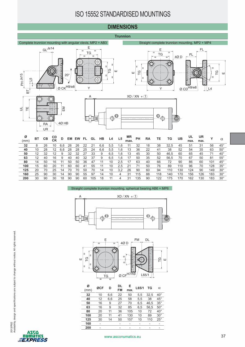
DIMENSIONSTrunnion
Ø (mm) BT CB CD
CK D EM EW FL GL HB L4 L5 MRmax. PH RA TE TG UB UL
max.URmax. Y α
32 8 26 10 6,6 26 26 22 21 6,6 5,5 1,6 11 32 18 38 32,5 45 51 31 56 45°40 10 28 12 6,6 28 28 25 24 6,6 5,5 1,6 13 36 22 41 38 52 54 35 63 50°50 12 32 12 9 32 32 27 33 9 6,5 1,6 13 45 30 50 46,5 60 65 45 71 40°63 12 40 16 9 40 40 32 37 9 6,5 1,6 17 50 35 52 56,5 70 67 50 81 55°80 14 50 16 11 50 50 36 47 11 10 2,5 17 63 40 66 72 90 86 60 101 45°
100 15 60 20 11 60 60 41 55 11 10 2,5 21 71 50 76 89 110 96 70 128 35°125 20 70 25 14 70 70 50 70 14 10 3,2 26 90 60 94 110 130 124 90 149 30°160 25 90 30 14 90 90 55 97 14 10 4 31 115 88 118 140 170 156 126 183 30°200 30 90 30 18 90 90 60 105 18 11 4 31 135 90 122 175 170 162 130 183 30°
Ø (mm) ØCF D DL
FME
max. L65/1 TG α
32 10 6,6 22 50 5,5 32,5 40°40 12 6,6 25 58 5,5 38 45°50 16 9 27 70 6,5 46,5 35°63 16 9 32 85 6,5 56,5 50°80 20 11 36 105 10 72 40°
100 20 11 41 130 10 89 30°125 30 14 50 157 10 110 25°160 - - - - - -200 - - - - - -
Complete trunnion mounting with angular clevis, MP2 + AB3
Straight complete trunnion mounting, spherical bearing AB6 + MP6
Y
E
=
=
TG
=
=
=
= =
=TG
GLJs14
Ø CKH9/e8PH
Js1
5
TE
UL
RA
UR
4Ø HB
L5
20°
BT
EE
TG=
= =
=
= ===
TGE
Y
4Ø D
FL
FL
Ø CDH9/e8
TG
L4
E
EM
A XD / XN + 1
Straight complete trunnion mounting, MP2 + MP4
E
TG
=
= =
=
= ===
TGE
4Ø DDLFM
Ø CFH7/h9
TG E
L65/1
A XD / XN + 1
ISO 15552 STANDARDISED MOUNTINGS20
13/R
02A
vaila
bilit
y, d
esig
n an
d sp
ecifi
catio
ns a
re s
ubje
ct to
cha
nge
with
out n
otic
e. A
ll rig
hts
rese
rved
.
38 www.asconumatics.eu
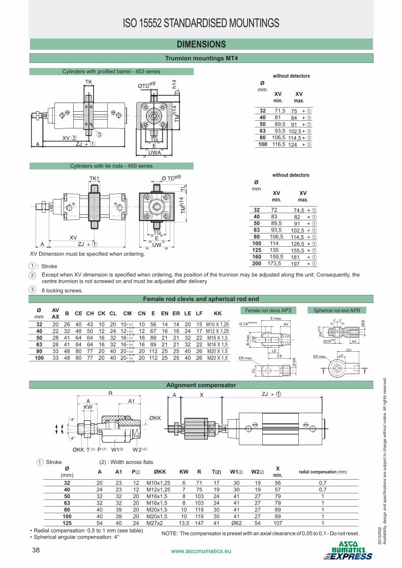
TK1
ZJ + 1XV
A
Ø TDe9
EUW
==
==
TM
h14
TL
==TG
DIMENSIONSTrunnion mountings MT4
Female rod clevis AP2 Spherical rod end AP6
Cylinders�with�tie�rods�-�450�series
Cylinders�with�profiled�barrel�-�453�series
ØCNH9 AX
ØK
K
EN
h12
4° 4°
CH
LFER max.
E max.
Ø CKH9/d10 AV
LECE
CM
B m
ax.
CL
ER max.
Ø K
K
Female rod clevis and spherical rod end
Ø mm
AVAX B CE CH CK CL CM CN E EN ER LE LF KK
32 20 26 40 43 10 20 10 10 56 14 14 20 15 M10 X 1,2540 22 32 48 50 12 24 12 12 67 16 16 24 17 M12 X 1,2550 28 41 64 64 16 32 16 16 89 21 21 32 22 M16 X 1,563 28 41 64 64 16 32 16 16 89 21 21 32 22 M16 X 1,580 33 48 80 77 20 40 20 20 112 25 25 40 26 M20 X 1,5
100 33 48 80 77 20 40 20 20 112 25 25 40 26 M20 X 1,5
+ 0,5+ 0,15+ 0,5+ 0,15+ 0,5+ 0,15+ 0,5+ 0,15+ 0,6+ 0,15+ 0,6+ 0,15
Ø mm
without detectors
XVmin.
XVmax.
32 71,5 75 + ➀40 81 84 + ➀50 89,5 91 + ➀63 93,5 102,5 + ➀80 106,5 114,5 + ➀
100 116,5 124 + ➀
Ø mm
without detectors
XVmin.
XVmax.
32 72 74,5 + ➀40 83 82 + ➀50 89,5 91 + ➀63 93,5 102,5 + ➀80 106,5 114,5 + ➀
100 114 126,5 + ➀125 135 155,5 + ➀160 159,5 181 + ➀200 173,5 197 + ➀1 : Stroke
2 ������Except�when�XV�dimension�is�specified�when�ordering,�the�position�of�the�trunnion�may�be�adjusted�along�the�unit.�Consequently,�the�centre�trunnion�is�not�screwed�on�and�must�be�adjusted�after�delivery
3 8 locking screws.
AXV 2
ZJ + 1
TK
3
ØTDe9
TM
h14
TLh1
4
EUWA
TG=== =
= =
AKW
A1
R
4°
4°
ØKK
W2 (2)W1(2)P (2 )T (2 )ØKK
ZJ + 1A X
Ø (mm) A A1 P(2) ØKK KW R T(2) W1(2) W2(2) X
min. radial compensation (mm)
32 20 23 12 M10x1,25 6 71 17 30 19 56 0,740 24 23 12 M12x1,25 7 75 19 30 19 57 0,750 32 32 20 M16x1,5 8 103 24 41 27 79 163 32 32 20 M16x1,5 8 103 24 41 27 79 180 40 39 20 M20x1,5 10 119 30 41 27 89 1
100 40 39 20 M20x1,5 10 119 30 41 27 89 1125 54 40 24 M27x2 13,5 147 41 Ø62 54 107 1
1 � Stroke� (2)�:�Width�across�flats
Alignment compensator
NOTE:��The�compensator�is�preset�with�an�axial�clearance�of�0,05�to�0,1�-�Do�not�reset.•�Radial�compensation:�0,5�to�1�mm�(see�table)•�Spherical�angular�compensation:�4°
ISO 15552 STANDARDISED MOUNTINGS
XV�Dimension�must�be�specified�when�ordering.
2013
/R02
Ava
ilabi
lity,
des
ign
and
spec
ifica
tions
are
sub
ject
to c
hang
e w
ithou
t not
ice.
All
right
s re
serv
ed.
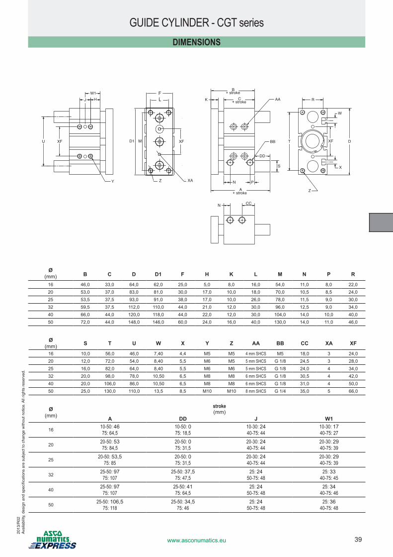
39www.asconumatics.eu
2013
/R02
Ava
ilabi
lity,
des
ign
and
spec
ifica
tions
are
sub
ject
to c
hang
e w
ithou
t not
ice.
All
right
s re
serv
ed.
GUIDE CYLINDER - CGT seriesDIMENSIONS
FL
D1 M
XA
H
W1
J
W
X
Y Z
U
R
Z
N CC
V1 XF XFXF T
A
N P
S
B
K C AA
BB
DD
D
+ stroke
+ stroke
+ stroke
Ø (mm) B C D D1 F H K L M N P R
16 46,0 33,0 64,0 62,0 25,0 5,0 8,0 16,0 54,0 11,0 8,0 22,020 53,0 37,0 83,0 81,0 30,0 17,0 10,0 18,0 70,0 10,5 8,5 24,025 53,5 37,5 93,0 91,0 38,0 17,0 10,0 26,0 78,0 11,5 9,0 30,032 59,5 37,5 112,0 110,0 44,0 21,0 12,0 30,0 96,0 12,5 9,0 34,040 66,0 44,0 120,0 118,0 44,0 22,0 12,0 30,0 104,0 14,0 10,0 40,050 72,0 44,0 148,0 146,0 60,0 24,0 16,0 40,0 130,0 14,0 11,0 46,0
Ø (mm)
stroke (mm)
A DD J W1
16 10-50: 4675: 64,5
10-50: 075: 18,5
10-30: 2440-75: 44
10-30: 1740-75: 27
20 20-50: 5375: 84,5
20-50: 075: 31,5
20-30: 2440-75: 44
20-30: 2940-75: 39
25 20-50: 53,575: 85
20-50: 075: 31,5
20-30: 2440-75: 44
20-30: 2940-75: 39
32 25-50: 9775: 107
25-50: 37,575: 47,5
25: 2450-75: 48
25: 3340-75: 45
40 25-50: 9775: 107
25-50: 4175: 64,5
25: 2450-75: 48
25: 3440-75: 46
50 25-50: 106,575: 118
25-50: 34,575: 46
25: 2450-75: 48
25: 3640-75: 48
Ø (mm) S T U W X Y Z AA BB CC XA XF
16 10,0 56,0 46,0 7,40 4,4 M5 M5 4 mm SHCS M5 18,0 3 24,020 12,0 72,0 54,0 8,40 5,5 M6 M5 5 mm SHCS G 1/8 24,5 3 28,025 16,0 82,0 64,0 8,40 5,5 M6 M6 5 mm SHCS G 1/8 24,0 4 34,032 20,0 98,0 78,0 10,50 6,5 M8 M8 6 mm SHCS G 1/8 30,5 4 42,040 20,0 106,0 86,0 10,50 6,5 M8 M8 6 mm SHCS G 1/8 31,0 4 50,050 25,0 130,0 110,0 13,5 8,5 M10 M10 8 mm SHCS G 1/4 35,0 5 66,0
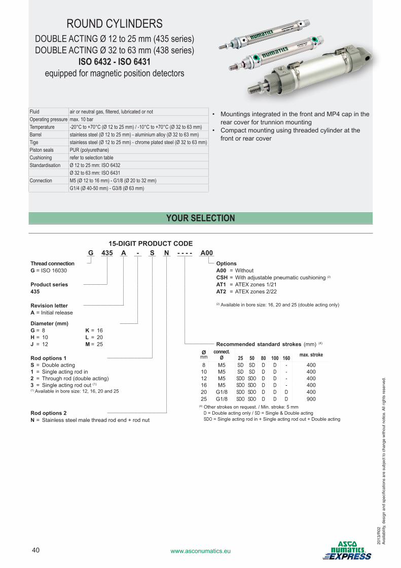
40 www.asconumatics.eu
2013
/R02
Ava
ilabi
lity,
des
ign
and
spec
ifica
tions
are
sub
ject
to c
hang
e w
ithou
t not
ice.
All
right
s re
serv
ed.
Fluid air or neutral gas, filtered, lubricated or notOperating pressure max. 10 barTemperature -20°C to +70°C (Ø 12 to 25 mm) / -10°C to +70°C (Ø 32 to 63 mm)Barrel stainless steel (Ø 12 to 25 mm) - aluminium alloy (Ø 32 to 63 mm)Tige stainless steel (Ø 12 to 25 mm) - chrome plated steel (Ø 32 to 63 mm)Piston seals PUR (polyurethane)Cushioning refer to selection tableStandardisation Ø 12 to 25 mm: ISO 6432
Ø 32 to 63 mm: ISO 6431Connection M5 (Ø 12 to 16 mm) - G1/8 (Ø 20 to 32 mm)
G1/4 (Ø 40-50 mm) - G3/8 (Ø 63 mm)
ROUND CYLINDERSDOUBLE ACTING Ø 12 to 25 mm (435 series)DOUBLE ACTING Ø 32 to 63 mm (438 series)
ISO 6432 - ISO 6431equipped for magnetic position detectors
• Mountings integrated in the front and MP4 cap in the rear cover for trunnion mounting
• Compact mounting using threaded cylinder at the front or rear cover
YOUR SELECTION
15-DIGIT PRODUCT CODEG 435 A - S N - - - - A00
Thread connection OptionsG = ISO 16030 A00 = Without
CSH�=�With�adjustable�pneumatic�cushioning�(2)
Product series AT1� =�ATEX�zones�1/21435 AT2� =�ATEX�zones�2/22
Revision letter (2)�Available�in�bore�size:�16,�20�and�25�(double�acting�only)
A = Initial release
Diameter (mm)G = 8 K = 16H = 10 L = 20J = 12 M = 25 Recommended standard strokes (mm) (4)
Ømm
connect.Ø max. strokeRod options 1 25 50 80 100 160
S = Double acting 8 M5 SD SD D D - 4001 = Single acting rod in 10 M5 SD SD D D - 4002 = Through rod (double acting) 12 M5 SDO SDO D D - 4003 = Single acting rod out (1) 16 M5 SDO SDO D D - 400(1)�Available�in�bore�size:�12,�16,�20�and�25 20 G1/8 SDO SDO D D D 400
25 G1/8 SDO SDO D D D 900(4) Other strokes on request. / Min. stroke: 5 mm
D = Double acting only / SD = Single & Double acting SDO = Single acting rod in + Single acting rod out + Double acting
Rod options 2N = Stainless steel male thread rod end + rod nut
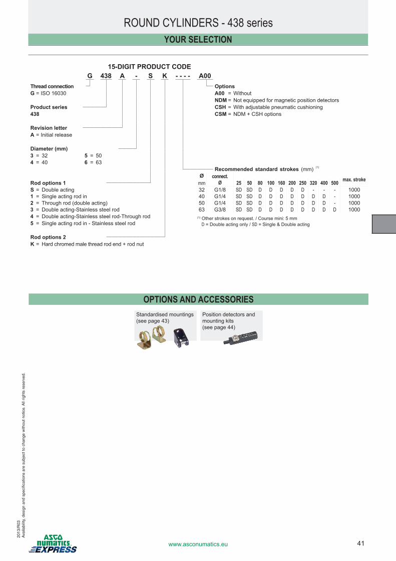
41www.asconumatics.eu
2013
/R03
Ava
ilabi
lity,
des
ign
and
spec
ifica
tions
are
sub
ject
to c
hang
e w
ithou
t not
ice.
All
right
s re
serv
ed.
OPTIONS AND ACCESSORIESStandardised mountings(see page 43)
Position detectors and mounting kits (see page 44)
ROUND CYLINDERS - 438 seriesYOUR SELECTION
15-DIGIT PRODUCT CODEG 438 A - S K - - - - A00
Thread connection OptionsG = ISO 16030 A00 = Without
NDM = Not equipped for magnetic position detectorsProduct series CSH�=�With�adjustable�pneumatic�cushioning438 CSM = NDM + CSH options
Revision letterA = Initial release
Diameter (mm)3 = 32 5 = 504 = 40 6 = 63
Recommended standard strokes (mm) (1)
Ømm
connect.Ø max. strokeRod options 1 25 50 80 100 160 200 250 320 400 500
S = Double acting 32 G1/8 SD SD D D D D D - - - 10001 = Single acting rod in 40 G1/4 SD SD D D D D D D D - 10002 = Through rod (double acting) 50 G1/4 SD SD D D D D D D D - 10003� =� Double�acting-Stainless�steel�rod 63 G3/8 SD SD D D D D D D D D 10004� =� Double�acting-Stainless�steel�rod-Through�rod (1) Other strokes on request. / Course mini: 5 mm
D = Double acting only / SD = Single & Double acting5� =� Single�acting�rod�in�-�Stainless�steel�rod
Rod options 2K = Hard chromed male thread rod end + rod nut
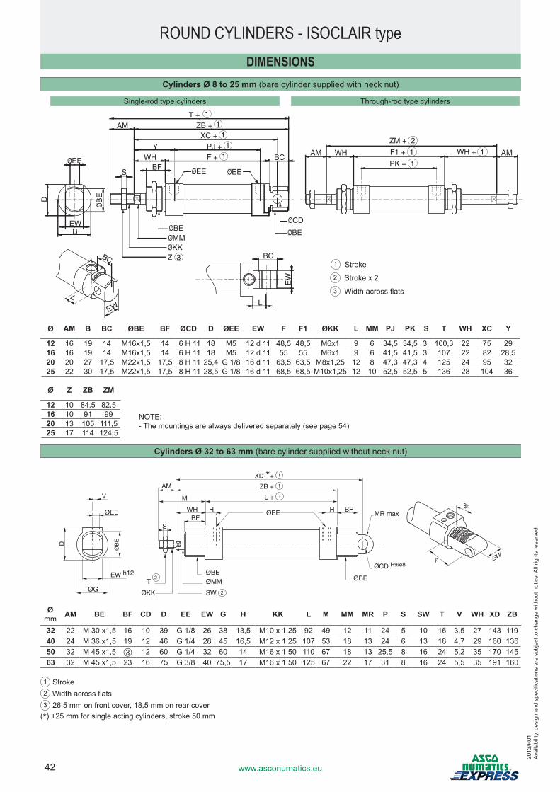
42 www.asconumatics.eu
ROUND CYLINDERS - ISOCLAIR typeDIMENSIONS
Cylinders Ø 8 to 25 mm (bare cylinder supplied with neck nut)
Ø AM B BC ØBE BF ØCD D ØEE EW F F1 ØKK L MM PJ PK S T WH XC Y
12 16 19 14 M16x1,5 14 6 H 11 18 M5 12 d 11 48,5 48,5 M6x1 9 6 34,5 34,5 3 100,3 22 75 2916 16 19 14 M16x1,5 14 6 H 11 18 M5 12 d 11 55 55 M6x1 9 6 41,5 41,5 3 107 22 82 28,520 20 27 17,5 M22x1,5 17,5 8 H 11 25,4 G 1/8 16 d 11 63,5 63,5 M8x1,25 12 8 47,3 47,3 4 125 24 95 3225 22 30 17,5 M22x1,5 17,5 8 H 11 28,5 G 1/8 16 d 11 68,5 68,5 M10x1,25 12 10 52,5 52,5 5 136 28 104 36
Ø Z ZB ZM
12 10 84,5 82,516 10 91 9920 13 105 111,525 17 114 124,5
Cylinders Ø 32 to 63 mm (bare cylinder supplied without neck nut)
WHBF
ØEE
S
L + M
ZB +AM
XD *+
BFHH
ØG
ØB
ED
ØBE
SW
ØBE
MR max
ØKK
T
ØEE
VBF
P EW
EW h122
1
1
1
ØMM
2
ØCD H9/e8
Ømm AM BE BF CD D EE EW G H KK L M MM MR P S SW T V WH XD ZB
32 22 M�30�x1,5 16 10 39 G 1/8 26 38 13,5 M10�x�1,25 92 49 12 11 24 5 10 16 3,5 27 143 11940 24 M�36�x1,5 19 12 46 G 1/4 28 45 16,5 M12�x�1,25 107 53 18 13 24 6 13 18 4,7 29 160 13650 32 M�45�x1,5 ➂ 12 60 G 1/4 32 60 14 M16�x�1,50 110 67 18 13 25,5 8 16 24 5,2 35 170 14563 32 M�45�x1,5 23 16 75 G 3/8 40 75,5 17 M16�x�1,50 125 67 22 17 31 8 16 24 5,5 35 191 160
1 Stroke2 Width�across�flats3 26,5 mm on front cover, 18,5 mm on rear cover
(*) +25 mm for single acting cylinders, stroke 50 mm
NOTE:-��The�mountings�are�always�delivered�separately�(see�page�54)
EW
BC
S
BC
BC
EW
L
EW B
L
D
ØB
E
ØEEØEE ØEE
ØBEØMM
Z 3ØKK
ØCD
ØBE
T +ZB +
XC +
PJ +F +
AM
YWH
BF
11
11
1 AM WH F1 + 1
ZM + 2
PK + 1
WH + 1 AM
Single-rod�type�cylinders Through-rod�type�cylinders
1 Stroke
2 ��Stroke�x�2
3 ��Width�across�flats
2013
/R01
Ava
ilabi
lity,
des
ign
and
spec
ifica
tions
are
sub
ject
to c
hang
e w
ithou
t not
ice.
All
right
s re
serv
ed.
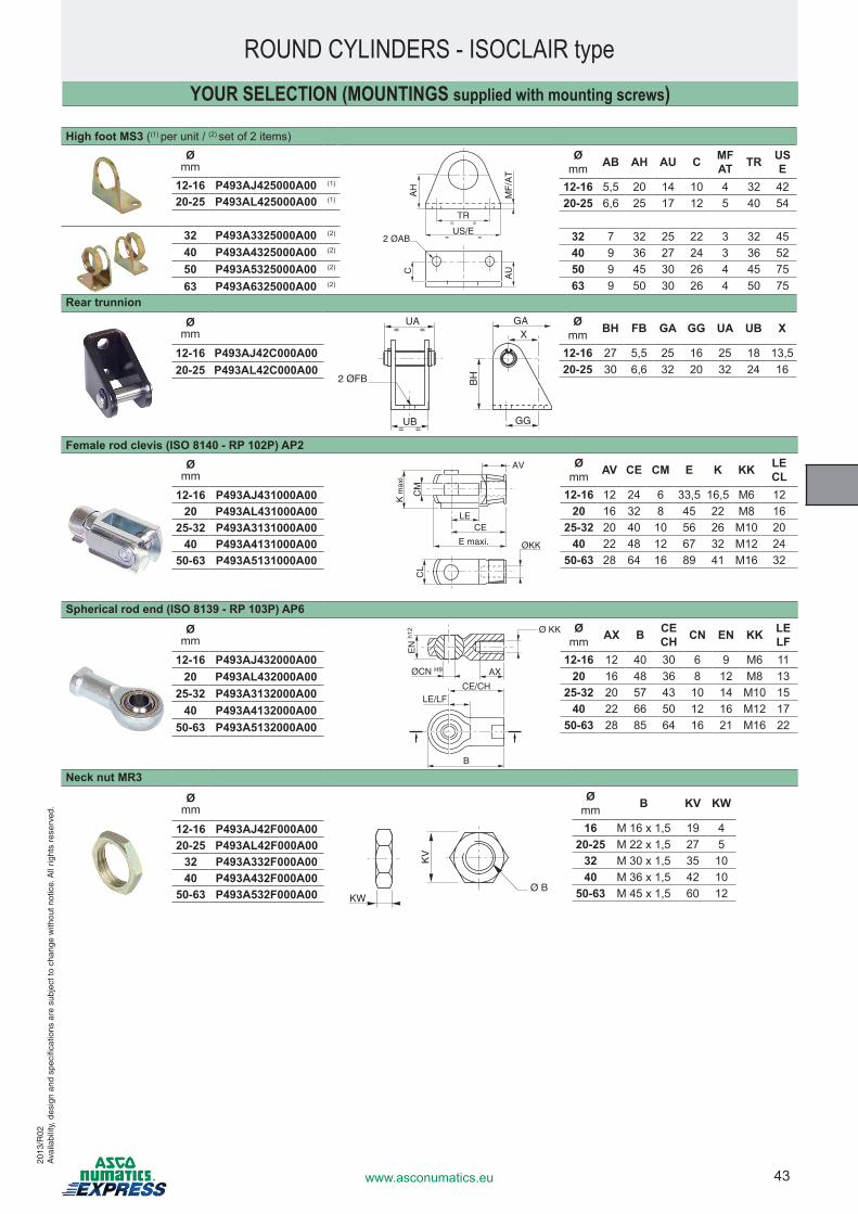
43www.asconumatics.eu
2013
/R02
Ava
ilabi
lity,
des
ign
and
spec
ifica
tions
are
sub
ject
to c
hang
e w
ithou
t not
ice.
All
right
s re
serv
ed.
ROUND CYLINDERS - ISOCLAIR type
High foot MS3 ((1) per unit / (2) set of 2 items)Ø
mm
TR= =
US/E= =
AH
AU
MF
/AT
2 ØAB
C
Ømm AB AH AU C MF
AT TR USE
12-16 5,5 20 14 10 4 32 4220-25 6,6 25 17 12 5 40 54
32 7 32 25 22 3 32 4540 9 36 27 24 3 36 5250 9 45 30 26 4 45 7563 9 50 30 26 4 50 75
12-16 P493AJ425000A00 (1)
20-25 P493AL425000A00 (1)
32 P493A3325000A00 (2)
40 P493A4325000A00 (2)
50 P493A5325000A00 (2)
63 P493A6325000A00 (2)
Rear trunnionØ
mm X
GG
2 ØFB BH
UA= =
UB= =
GA Ømm BH FB GA GG UA UB X
12-16 27 5,5 25 16 25 18 13,520-25 30 6,6 32 20 32 24 16
12-16 P493AJ42C000A0020-25 P493AL42C000A00
Female rod clevis (ISO 8140 - RP 102P) AP2Ø
mm
ØKKE maxi.
CM
AV
LECE
CL
K m
axi.
Ømm AV CE CM E K KK LE
CL12-16 12 24 6 33,5 16,5 M6 12
20 16 32 8 45 22 M8 1625-32 20 40 10 56 26 M10 20
40 22 48 12 67 32 M12 2450-63 28 64 16 89 41 M16 32
12-16 P493AJ431000A0020 P493AL431000A00
25-32 P493A3131000A0040 P493A4131000A00
50-63 P493A5131000A00
Spherical rod end (ISO 8139 - RP 103P) AP6
Ømm
ØCN H9
EN
h12 Ø KK
AX
CE/CHLE/LF
B
Ømm AX B CE
CH CN EN KK LELF
12-16 12 40 30 6 9 M6 1120 16 48 36 8 12 M8 13
25-32 20 57 43 10 14 M10 1540 22 66 50 12 16 M12 17
50-63 28 85 64 16 21 M16 22
12-16 P493AJ432000A0020 P493AL432000A00
25-32 P493A3132000A0040 P493A4132000A00
50-63 P493A5132000A00
Neck nut MR3
Ømm
KW
KV
Ø B
Ømm B KV KW
16 M�16�x�1,5 19 420-25 M�22�x�1,5 27 5
32 M�30�x�1,5 35 1040 M�36�x�1,5 42 10
50-63 M�45�x�1,5 60 12
12-16 P493AJ42F000A0020-25 P493AL42F000A00
32 P493A332F000A0040 P493A432F000A00
50-63 P493A532F000A00
YOUR SELECTION (MOUNTINGS supplied with mounting screws)
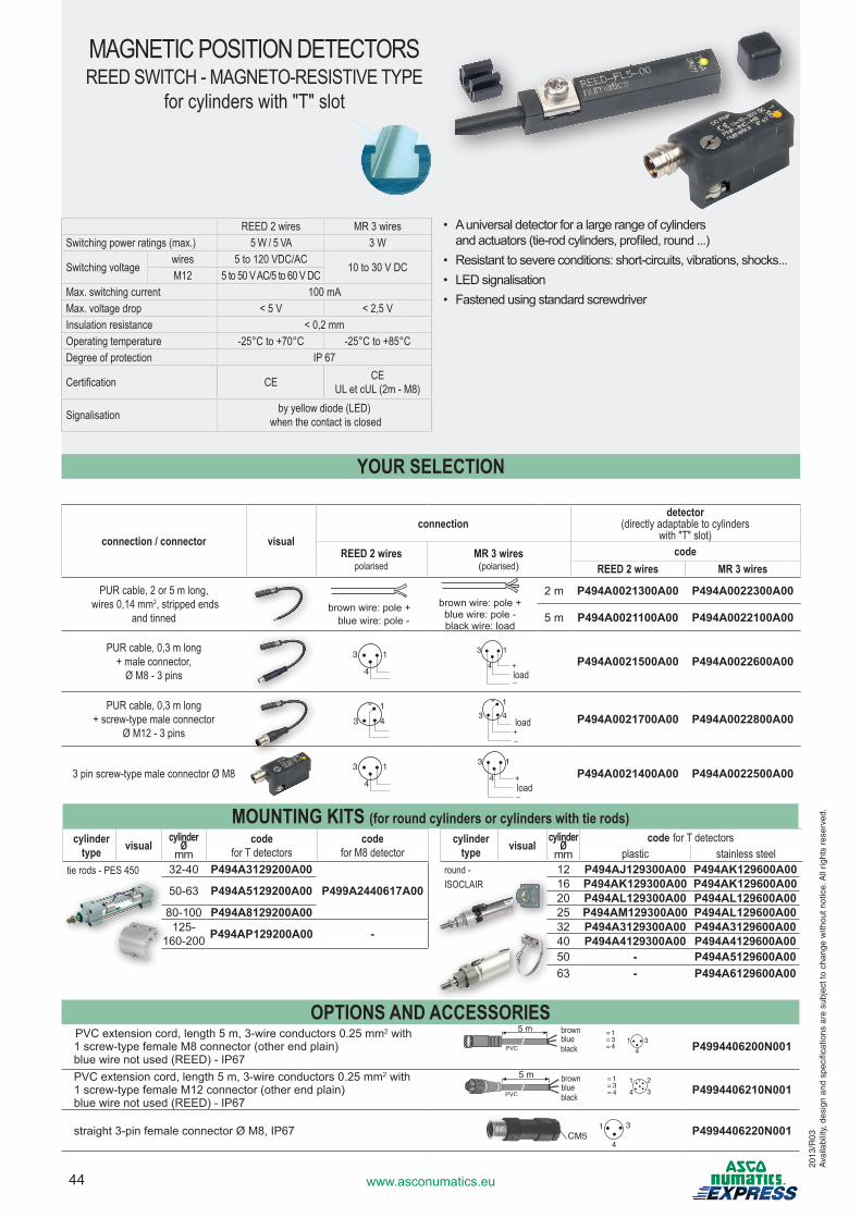
44 www.asconumatics.eu
REED 2 wires MR 3 wiresSwitching power ratings (max.) 5 W / 5 VA 3 W
Switching voltagewires 5 to 120 VDC/AC
10 to 30 V DC M12 5 to 50 V AC/5 to 60 V DC
Max. switching current 100 mAMax. voltage drop < 5 V < 2,5 VInsulation resistance < 0,2 mmOperating temperature -25°C to +70°C -25°C to +85°CDegree of protection IP 67
Certification CE CEUL et cUL (2m - M8)
Signalisation by yellow diode (LED) when the contact is closed
MAGNETIC POSITION DETECTORSREED SWITCH - MAGNETO-RESISTIVE TYPE
for cylinders with "T" slot
• A universal detector for a large range of cylinders and actuators (tie-rod�cylinders,�profiled,�round�...)
• Resistant�to�severe�conditions:�short-circuits,�vibrations,�shocks...• LED signalisation• Fastened using standard screwdriver
2013
/R03
Ava
ilabi
lity,
des
ign
and
spec
ifica
tions
are
sub
ject
to c
hang
e w
ithou
t not
ice.
All
right
s re
serv
ed.
OPTIONS AND ACCESSORIESPVC�extension�cord,�length�5�m,�3-wire�conductors�0.25�mm2 with 1�screw-type�female�M8�connector�(other�end�plain)blue�wire�not�used�(REED)�-�IP67
5 m = 1
= 4= 3 1
4
3PVC P4994406200N001
PVC�extension�cord,�length�5�m,�3-wire�conductors�0.25�mm2 with 1�screw-type�female�M12�connector�(other�end�plain)blue�wire�not�used�(REED)�-�IP67
5 m = 1
= 4= 3
1
4 3
2
PVC P4994406210N001
straight�3-pin�female�connector��M8,�IP67 1 3
4CM5 P4994406220N001
YOUR SELECTION
connection / connector visualconnection
detector(directly adaptable to cylinders
with "T" slot)REED 2 wires
polarisedMR 3 wires(polarised)
codeREED 2 wires MR 3 wires
PUR cable, 2 or 5 m long, wires 0,14 mm2, stripped ends
and tinnedbrown wire: pole + blue wire: pole�-
brown wire: pole +blue�wire:�pole�-black wire: load
2 m P494A0021300A00 P494A0022300A00
5 m P494A0021100A00 P494A0022100A00
PUR cable, 0,3 m long+ male connector,
Ø M8 - 3 pins
13
4
13
4 +
_
P494A0021500A00 P494A0022600A00
PUR cable, 0,3 m long+ screw-type male connector
Ø M12 - 3 pins
1
3 4
1
3 4
+_
P494A0021700A00 P494A0022800A00
3 pin screw-type male connector Ø M8 13
4
13
4 +
_
P494A0021400A00 P494A0022500A00
load
load
load
brown blue black
brown blue black
MOUNTING KITS (for round cylinders or cylinders with tie rods)cylinder
type visualcylinder
Ømm
codefor T detectors
codefor M8 detector
cylinder type visual
cylinder Ø
mmcode for T detectors
plastic stainless steeltie rods - PES 450 32-40 P494A3129200A00
P499A2440617A00
round - ISOCLAIR
12 P494AJ129300A00 P494AK129600A00
50-63 P494A5129200A00 16 P494AK129300A00 P494AK129600A0020 P494AL129300A00 P494AL129600A00
80-100 P494A8129200A00 25 P494AM129300A00 P494AL129600A00125-
160-200 P494AP129200A00 - 32 P494A3129300A00 P494A3129600A0040 P494A4129300A00 P494A4129600A0050 - P494A5129600A0063 - P494A6129600A00
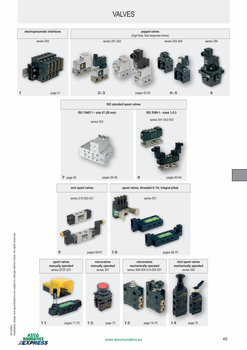
45www.asconumatics.eu
VALVES
spool valvesmanually operated
series ZF2F-551
microvalvesmanually operated
series 307
microvalves mechanically operated
series 308-309-310-550-551
mini spool valvesmechanically operated
series 550
11 pages 71-72 12 page 73 13 page 74-75 14 page 76
electropneumatic interfaces poppet valves(high flow, fast response times)
series 304 series 261-262 series 263-264 series 284
1 page 51 2-3 pages 52-55 4-5 6
ISO standard spool valves
ISO 15407-1 - size 01 (26 mm) ISO 5599-1 - sizes 1-2-3
series 503 series 541-542-543
7 page 56 pages 56-59 8 pages 60-64
mini spool valves spool valves, threaded G 1/4, integral pilots
series 519-520-521 series 551
9 pages 65-67 10 pages 68-70
2013
/R01
Ava
ilabi
lity,
des
ign
and
spec
ifica
tions
are
sub
ject
to c
hang
e w
ithou
t not
ice.
All
right
s re
serv
ed.
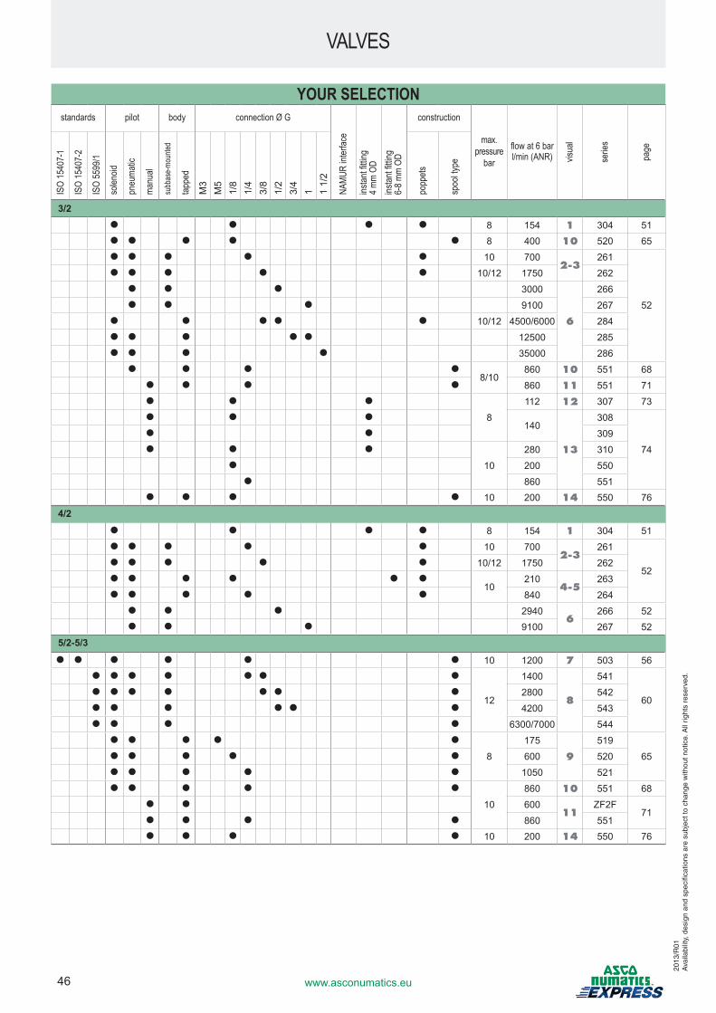
46 www.asconumatics.eu
VALVES
YOUR SELECTIONstandards pilot body connection Ø G
NAMU
R int
erfac
e
instan
t fittin
g 4 m
m OD
instan
t fittin
g 6-
8 mm
OD
construction
max. pressure
bar
flow at 6 barl/min (ANR) vis
ual
serie
s
page
ISO
1540
7-1
ISO
1540
7-2
ISO
5599
/1
solen
oid
pneu
matic
manu
al
subb
ase-m
ounte
d
tappe
d
popp
ets
spoo
l type
M3
M5
1/8
1/4
3/8
1/2
3/4
1 1 1/
2
3/2● ● ● ● 8 154 1 304 51● ● ● ● ● 8 400 10 520 65● ● ● ● ● 10 700
2-3261
52
● ● ● ● ● 10/12 1750 262● ● ● 3000
6
266● ● ● 9100 267
● ● ● ● ● 10/12 4500/6000 284● ● ● ● ● 12500 285● ● ● ● 35000 286
● ● ● ●8/10
860 10 551 68● ● ● ● 860 11 551 71● ● ●
8
112 12 307 73● ● ●
140
13
308
74
● ● 309● ● ●
10
280 310● 200 550
● 860 551● ● ● ● 10 200 14 550 76
4/2● ● ● ● 8 154 1 304 51● ● ● ● ● 10 700
2-3261
52● ● ● ● ● 10/12 1750 262● ● ● ● ● ●
10210
4-5263
● ● ● ● ● 840 264● ● ● 2940
6266 52
● ● ● 9100 267 525/2-5/3
● ● ● ● ● ● 10 1200 7 503 56● ● ● ● ● ● ●
12
1400
8
541
60● ● ● ● ● ● ● 2800 542● ● ● ● ● ● 4200 543● ● ● ● 6300/7000 544
● ● ● ● ●
8
175
9
519
65● ● ● ● ● 600 520● ● ● ● ● 1050 521● ● ● ● ●
10
860 10 551 68● ● 600
11ZF2F
71● ● ● ● 860 551● ● ● ● 10 200 14 550 76
2013
/R01
Ava
ilabi
lity,
des
ign
and
spec
ifica
tions
are
sub
ject
to c
hang
e w
ithou
t not
ice.
All
right
s re
serv
ed.
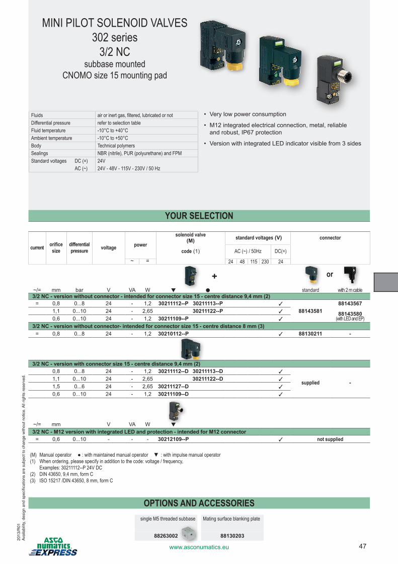
47www.asconumatics.eu
current orificesize
differential pressure voltage power
solenoid valve (M) standard voltages (V) connector
code (1) AC (~) / 50Hz DC(=)
~ = 24 48 115 230 24
~/= mm bar V VA W ▼ ● standard with 2 m cable3/2 NC - version without connector - intended for connector size 15 - centre distance 9,4 mm (2)
= 0,8 0...8 24 - 1,2 30211112--P 30211113--P 3
8814358188143567
88143580(with LED and EP)
1,1 0...10 24 - 2,65 30211122--P 3
0,6 0...10 24 - 1,2 30211109--P 3
3/2 NC - version without connector- intended for connector size 15 - centre distance 8 mm (3)= 0,8 0...8 24 - 1,2 30210112--P 3 88130211 -
3/2 NC - version with connector size 15 - centre distance 9,4 mm (2)0,8 0...8 24 - 1,2 30211112--D 30211113--D 3
supplied -1,1 0...10 24 - 2,65 30211122--D 3
1,5 0...6 24 - 2,65 30211127--D 3
0,6 0...10 24 - 1,2 30211109--D 3
~/= mm V VA W ▼
3/2 NC - M12 version with integrated LED and protection - intended for M12 connector= 0,6 0...10 - - - 30212109--P 3 not supplied
(M) Manual operator ● : with maintained manual operator ▼ : with impulse manual operator(1) When ordering, please specify in addition to the code: voltage / frequency,
Examples: 30211112--P 24V DC(2) DIN 43650, 9,4 mm, form C(3) ISO 15217 /DIN 43650, 8 mm, form C
MINI PILOT SOLENOID VALVES302 series
3/2 NCsubbase mounted
CNOMO size 15 mounting pad
Fluids air or inert gas, filtered, lubricated or notDifferential pressure refer to selection tableFluid temperature -10°C to +40°CAmbient temperature -10°C to +50°CBody Technical polymersSealings NBR (nitrile), PUR (polyurethane) and FPMStandard voltages DC (=) 24V AC (~) 24V - 48V - 115V - 230V / 50 Hz
• Very low power consumption
• M12 integrated electrical connection, metal, reliable and robust, IP67 protection
• Version with integrated LED indicator visible from 3 sides
YOUR SELECTION
+ or
OPTIONS AND ACCESSORIESsingle M5 threaded subbase Mating surface blanking plate
88263002 88130203
2013
/R01
Ava
ilabi
lity,
des
ign
and
spec
ifica
tions
are
sub
ject
to c
hang
e w
ithou
t not
ice.
All
right
s re
serv
ed.
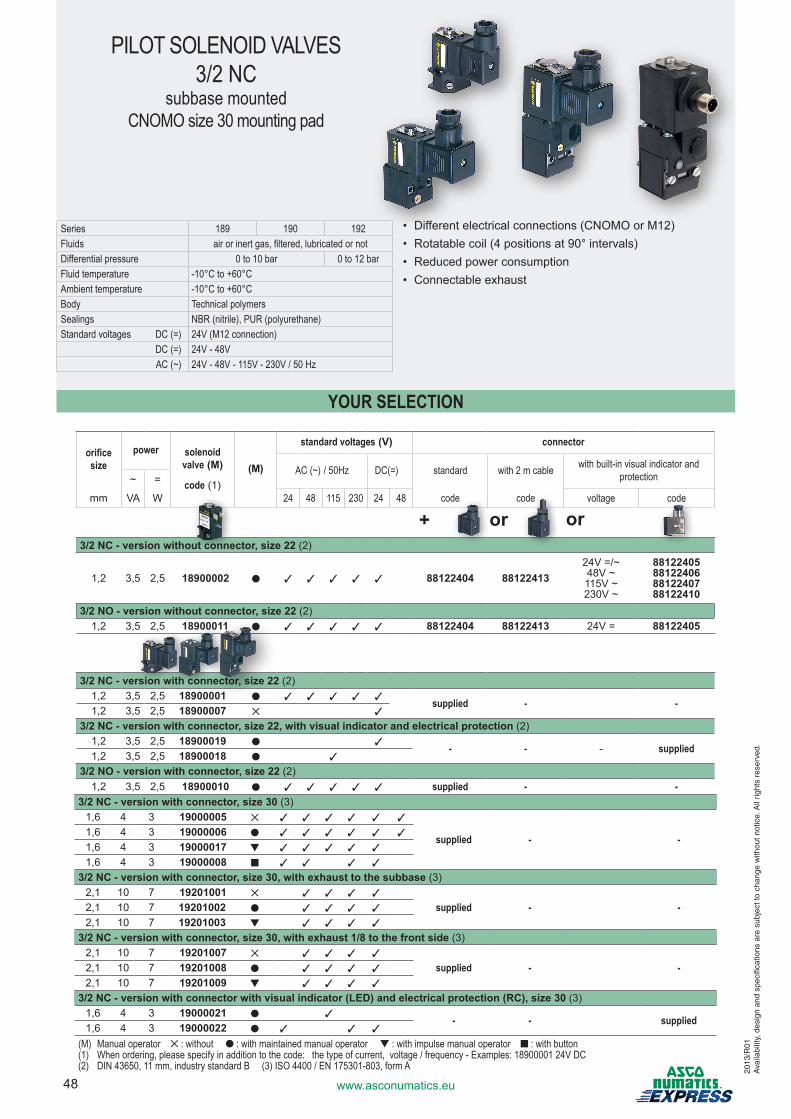
48 www.asconumatics.eu
YOUR SELECTION
PILOT SOLENOID VALVES3/2 NC
subbase mountedCNOMO size 30 mounting pad
Series 189 190 192Fluids air or inert gas, filtered, lubricated or notDifferential pressure 0 to 10 bar 0 to 12 barFluid temperature -10°C to +60°CAmbient temperature -10°C to +60°CBody Technical polymersSealings NBR (nitrile), PUR (polyurethane)Standard voltages DC (=) 24V (M12 connection) DC (=) 24V - 48V AC (~) 24V - 48V - 115V - 230V / 50 Hz
• Different electrical connections (CNOMO or M12)• Rotatable coil (4 positions at 90° intervals)• Reduced power consumption• Connectable exhaust
orificesize
power solenoid valve (M)
code (1)(M)
standard voltages (V) connector
AC (~) / 50Hz DC(=) standard with 2 m cable with built-in visual indicator and protection~ =
mm VA W 24 48 115 230 24 48 code code voltage code
3/2 NC - version without connector, size 22 (2)
1,2 3,5 2,5 18900002 ● 3 3 3 3 3 88122404 8812241324V =/~48V ~115V ~230V ~
88122405881224068812240788122410
3/2 NO - version without connector, size 22 (2) 1,2 3,5 2,5 18900011 ● 3 3 3 3 3 88122404 88122413 24V = 88122405
3/2 NC - version with connector, size 22 (2) 1,2 3,5 2,5 18900001 ● 3 3 3 3 3 supplied - -1,2 3,5 2,5 18900007 ✕ 3
3/2 NC - version with connector, size 22, with visual indicator and electrical protection (2) 1,2 3,5 2,5 18900019 ● 3 - - - supplied1,2 3,5 2,5 18900018 ● 3
3/2 NO - version with connector, size 22 (2) 1,2 3,5 2,5 18900010 ● 3 3 3 3 3 supplied - -
3/2 NC - version with connector, size 30 (3) 1,6 4 3 19000005 ✕ 3 3 3 3 3 3
supplied - -1,6 4 3 19000006 ● 3 3 3 3 3 3
1,6 4 3 19000017 ▼ 3 3 3 3 3
1,6 4 3 19000008 n 3 3 3 3
3/2 NC - version with connector, size 30, with exhaust to the subbase (3) 2,1 10 7 19201001 ✕ 3 3 3 3
supplied - -2,1 10 7 19201002 ● 3 3 3 3
2,1 10 7 19201003 ▼ 3 3 3 3
3/2 NC - version with connector, size 30, with exhaust 1/8 to the front side (3) 2,1 10 7 19201007 ✕ 3 3 3 3
supplied - -2,1 10 7 19201008 ● 3 3 3 3
2,1 10 7 19201009 ▼ 3 3 3 3
3/2 NC - version with connector with visual indicator (LED) and electrical protection (RC), size 30 (3) 1,6 4 3 19000021 ● 3 - - supplied1,6 4 3 19000022 ● 3 3 3
(M) Manual operator ✕ : without ● : with maintained manual operator ▼ : with impulse manual operator n : with button(1) When ordering, please specify in addition to the code: the type of current, voltage / frequency - Examples: 18900001 24V DC(2) DIN 43650, 11 mm, industry standard B (3) ISO 4400 / EN 175301-803, form A
+ or or
2013
/R01
Ava
ilabi
lity,
des
ign
and
spec
ifica
tions
are
sub
ject
to c
hang
e w
ithou
t not
ice.
All
right
s re
serv
ed.
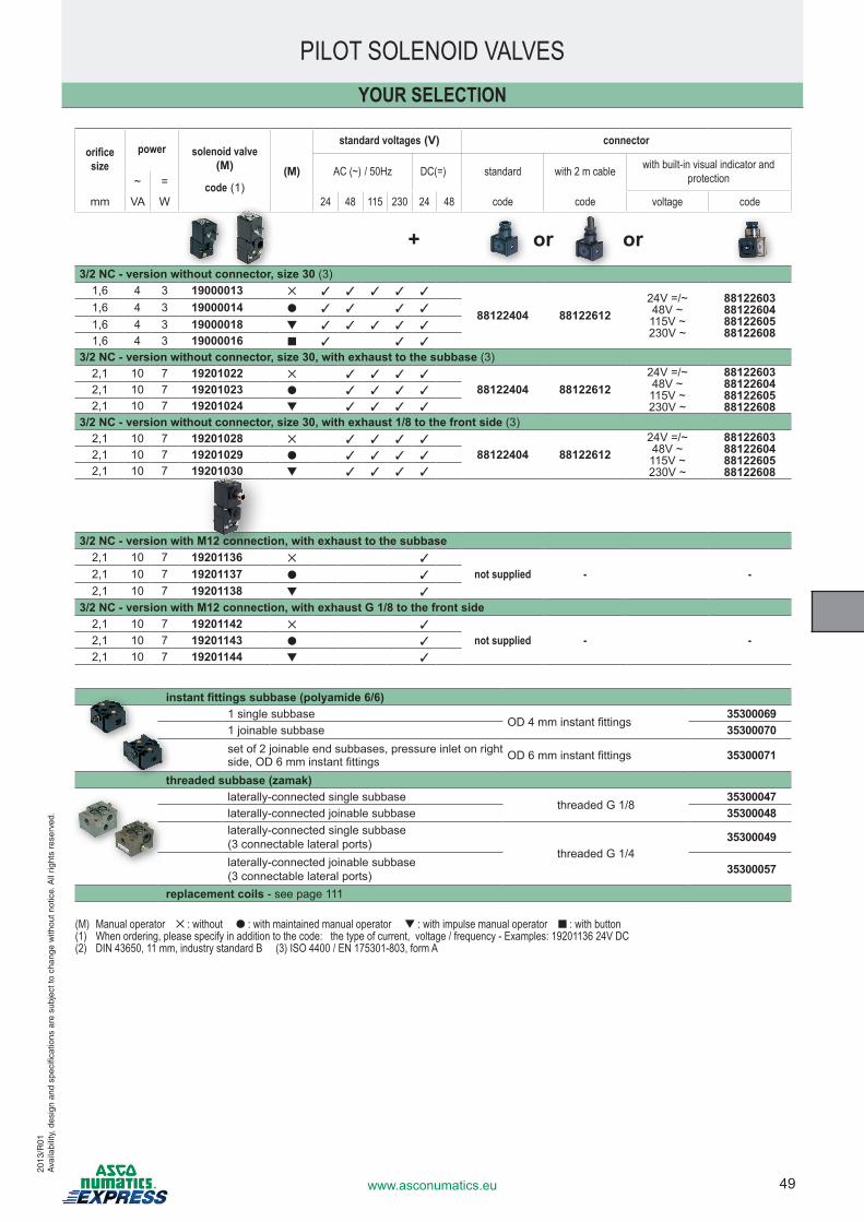
49www.asconumatics.eu
instant fittings subbase (polyamide 6/6)1 single subbase
OD 4 mm instant fittings35300069
1 joinable subbase 35300070set of 2 joinable end subbases, pressure inlet on right side, OD 6 mm instant fittings OD 6 mm instant fittings 35300071
threaded subbase (zamak)laterally-connected single subbase
threaded G 1/835300047
laterally-connected joinable subbase 35300048laterally-connected single subbase(3 connectable lateral ports)
threaded G 1/435300049
laterally-connected joinable subbase(3 connectable lateral ports) 35300057
replacement coils - see page 111
YOUR SELECTION
PILOT SOLENOID VALVES
orificesize
power solenoid valve (M)
code (1)
standard voltages (V) connector
(M) AC (~) / 50Hz DC(=) standard with 2 m cable with built-in visual indicator and protection~ =
mm VA W 24 48 115 230 24 48 code code voltage code
3/2 NC - version without connector, size 30 (3) 1,6 4 3 19000013 ✕ 3 3 3 3 3
88122404 8812261224V =/~48V ~115V ~230V ~
88122603881226048812260588122608
1,6 4 3 19000014 ● 3 3 3 3
1,6 4 3 19000018 ▼ 3 3 3 3 3
1,6 4 3 19000016 n 3 3 3
3/2 NC - version without connector, size 30, with exhaust to the subbase (3) 2,1 10 7 19201022 ✕ 3 3 3 3
88122404 8812261224V =/~48V ~115V ~230V ~
88122603881226048812260588122608
2,1 10 7 19201023 ● 3 3 3 3
2,1 10 7 19201024 ▼ 3 3 3 3
3/2 NC - version without connector, size 30, with exhaust 1/8 to the front side (3) 2,1 10 7 19201028 ✕ 3 3 3 3
88122404 8812261224V =/~48V ~115V ~230V ~
88122603881226048812260588122608
2,1 10 7 19201029 ● 3 3 3 3
2,1 10 7 19201030 ▼ 3 3 3 3
3/2 NC - version with M12 connection, with exhaust to the subbase2,1 10 7 19201136 ✕ 3
not supplied - -2,1 10 7 19201137 ● 3
2,1 10 7 19201138 ▼ 3
3/2 NC - version with M12 connection, with exhaust G 1/8 to the front side2,1 10 7 19201142 ✕ 3
not supplied - -2,1 10 7 19201143 ● 3
2,1 10 7 19201144 ▼ 3
+ or or
2013
/R01
Ava
ilabi
lity,
des
ign
and
spec
ifica
tions
are
sub
ject
to c
hang
e w
ithou
t not
ice.
All
right
s re
serv
ed.
(M) Manual operator ✕ : without ● : with maintained manual operator ▼ : with impulse manual operator n : with button(1) When ordering, please specify in addition to the code: the type of current, voltage / frequency - Examples: 19201136 24V DC(2) DIN 43650, 11 mm, industry standard B (3) ISO 4400 / EN 175301-803, form A
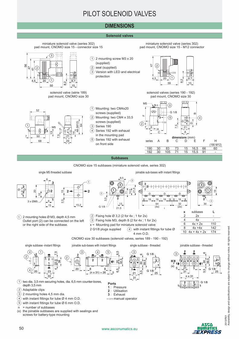
50 www.asconumatics.eu
PILOT SOLENOID VALVESDIMENSIONSSolenoid valves
miniature solenoid valve (series 302) pad mount, CNOMO size 15 - connector size 15
miniature solenoid valve (series 302) pad mount, CNOMO size 15 - M12 connector
41
4,5 20
50
9,7
158,2
4756
90°
2
3
1
3
12
4,5 20
39
9,7
158,2
47 2
1
3
12
solenoid valve (série 189) pad mount, CNOMO size 30
solenoid valves (series 190 - 192) pad mount, CNOMO size 30
1
2
52
7,513 14
48 (
M12
)64
7 50
M5
68= =
= =
==
21
29
360° 3
1
7,5
7 E
CH
DB
F
= =
= =21
A
360°
1
3
3
M5
G 1/8
2
32
3
5 4
Subbases
CNOMO size 15 subbases (miniature solenoid valve, series 302)
single M5 threaded subbase joinable sub-bases with instant fittings
CNOMO size 30 subbases (solenoid valves, series 189 - 190 - 192)
single subbase -instant fittings joinable sub-bases with instant fittings single subbase - threaded joinable subbase - threaded
20 23
47,
522
,5 38
33= =
= =
1
2
12
14
4
2
20
6,5
206,
532
,5
8 8(n x 31) + 26 5
11
2
2 2
3 4 5
2
1
2
251
2
3,5
630 39
,5
21
31= =
= =
3G 1/8
G 1/8
2 2
11
3,5
306
39,5
5(x)
52131
= =n x 31
3
G 1/8
G 1/8
12
25
2 211
dimensions (mm)series A B C D E F H
(190 M12)190 30 83 73 15 16,5 66 60192 30 105 71 15 15,5 91 -
1 two dia. 3,5 mm securing holes, dia. 6,5 mm counter-bores, depth 3,5 mm
2 Adaptable clips3 2 mounting holes 4,5 mm dia.4 with instant fittings for tube Ø 4 mm O.D.5 with instant fittings for tube Ø 6 mm O.D.
n = number of subbases(x) the joinable subbases are supplied with sealings and
screws for battery-type mounting
manual operator
1 2 mounting screw M3 x 20 (supplied)
2 seal (supplied)3 Version with LED and electrical
protection
2
3
2
64 (4x)
L
32 30 (2x)
16 8 8 8 8 16 16 16
3
1 9 1
13
21,5
8,5
3 3
1 1 5 , 1 2
5 , 4 1 1 1
5 , 3
2
G 1/8
2
4
15
3 x ØM515,2
51
02
01
9
6
1
3
21
3
2 2 2
5,2
1
1 2 mounting holes Ø M3, depth 4,5 mm Outlet port (2) can be connected on the left
or the right side of the subbase.
2 Fixing hole Ø 3,2 (2 for 4x ; 1 for 2x)3 Fixing hole M3, depth 8 (2 for 4x ; 1 for 2x)
x = Mounting pad for miniature solenoid valve2 G1/8 plugs supplied with instant fittings for tube Ø
4 mm O.D.4
x subbases L2 2x - 4 4x -6 4x + 2x 1108 4x +4x 142
10 4x + 4x + 2x 174
1 Mounting: two CM4x20 screws (supplied)
2 Mounting: two CM4 x 33,5 screws (supplied)
3 Series 1904 Series 192 with exhaust
in the mounting pad5 Series 192 with exhaust
on front side
Ports1 : Pressure2 : Utilisation3 : Exhaust
2013
/R01
Ava
ilabi
lity,
des
ign
and
spec
ifica
tions
are
sub
ject
to c
hang
e w
ithou
t not
ice.
All
right
s re
serv
ed.
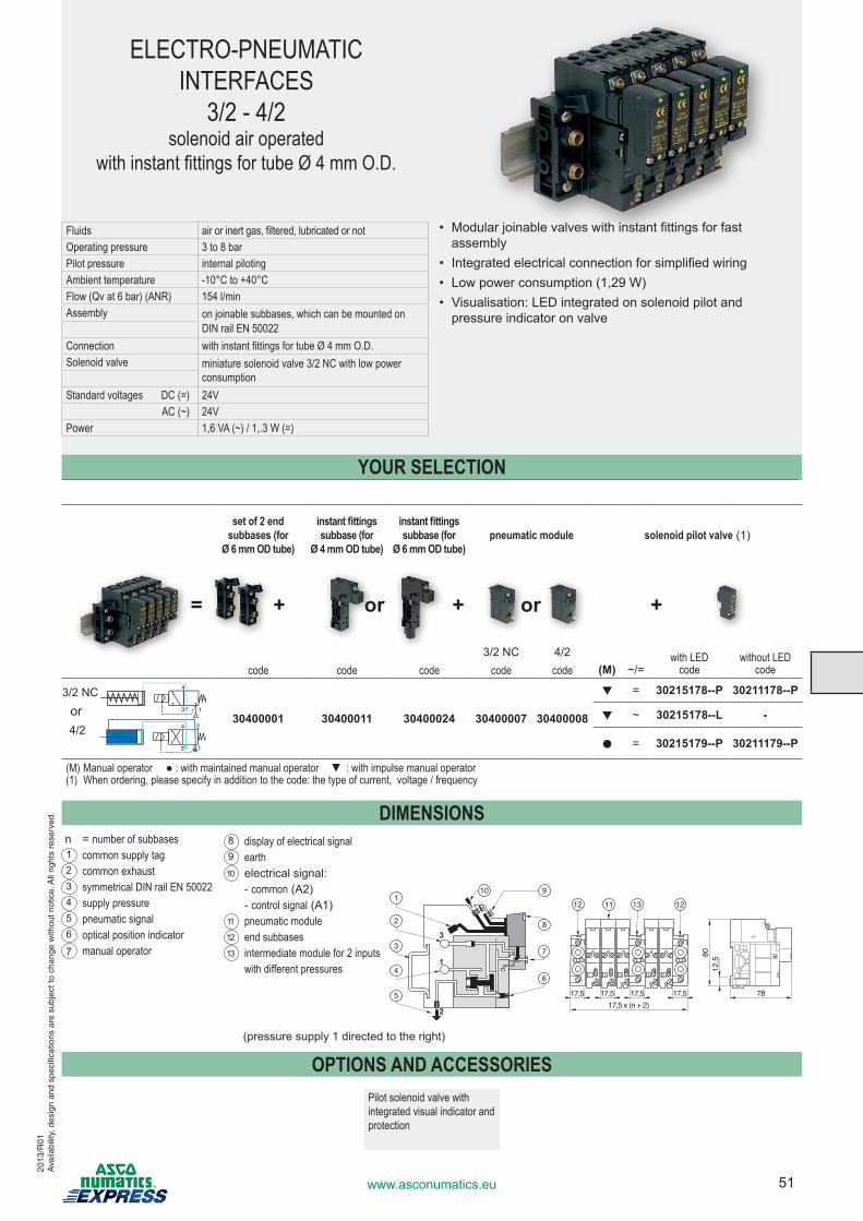
51www.asconumatics.eu
ELECTRO-PNEUMATIC INTERFACES
3/2 - 4/2solenoid air operated
with instant fittings for tube Ø 4 mm O.D.
Fluids air or inert gas, filtered, lubricated or notOperating pressure 3 to 8 barPilot pressure internal pilotingAmbient temperature -10°C to +40°CFlow (Qv at 6 bar) (ANR) 154 l/min Assembly on joinable subbases, which can be mounted on
DIN rail EN 50022Connection with instant fittings for tube Ø 4 mm O.D.Solenoid valve miniature solenoid valve 3/2 NC with low power
consumptionStandard voltages DC (=) 24V AC (~) 24V
Power 1,6 VA (~) / 1,.3 W (=)
• Modular joinable valves with instant fittings for fast assembly
• Integrated electrical connection for simplified wiring• Low power consumption (1,29 W)• Visualisation: LED integrated on solenoid pilot and
pressure indicator on valve
set of 2 end subbases (for
Ø 6 mm OD tube)
instant fittings subbase (for
Ø 4 mm OD tube)
instant fittings subbase (for
Ø 6 mm OD tube)pneumatic module solenoid pilot valve (1)
3/2 NC 4/2 with LED without LEDcode code code code code (M) ~/= code code
30400001 30400011 30400024 30400007 30400008
▼ = 30215178--P 30211178--P
▼ ~ 30215178--L -
● = 30215179--P 30211179--P
(M) Manual operator ● : with maintained manual operator ▼ : with impulse manual operator(1) When ordering, please specify in addition to the code: the type of current, voltage / frequency
DIMENSIONS
OPTIONS AND ACCESSORIESPilot solenoid valve with integrated visual indicator and protection
= + or + or +
1
2
3
910
7
6
8
5
4
3
2
1
17,5 17,5 17,5 78
17,5 x (n + 2)
17,5
4 5
3131
2 3
31
1
12,5
80
1112 13 12
2
3
4
1
(pressure supply 1 directed to the right)
or3/2 NC
4/2
3
4
1
YOUR SELECTION
n = number of subbases1 common supply tag2 common exhaust3 symmetrical DIN rail EN 500224 supply pressure5 pneumatic signal6 optical position indicator7 manual operator
8 display of electrical signal9 earth10 electrical signal: - common (A2) - control signal (A1)11 pneumatic module12 end subbases13 intermediate module for 2 inputs
with different pressures
2013
/R01
Ava
ilabi
lity,
des
ign
and
spec
ifica
tions
are
sub
ject
to c
hang
e w
ithou
t not
ice.
All
right
s re
serv
ed.
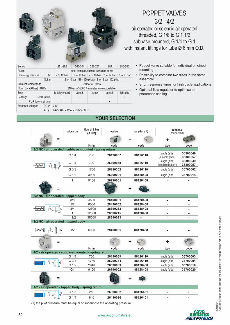
52 www.asconumatics.eu
POPPET VALVES3/2 - 4/2
air operated or solenoid air operatedthreaded, G 1/8 to G 1 1/2
subbase mounted, G 1/4 to G 1with instant fittings for tube Ø 6 mm O.D.
Series 261-262 263-264 266-267 284 285-286Fluids air or inert gas, filtered, lubricated or notOperating pressure Air. 2 to 12 bar 2 to 10 bar 2 to 16 bar 2 to 12 bar 2 to 16 bar Sol air 2 to 10 bar (189 - 190 pilots) - 2 to 12 bar (192 pilot)Ambient temperature -10°C to +60°CFlow (Qv at 6 bar) (ANR) 210 up to 35000 l/min (refer to selection table)Body light alloy, treated zamak zamak zamak light alloySealings NBR (nitrile) • • • • • PUR (polyurethane) • •Standard voltages DC (=) 24V AC (~) 24V - 48V - 115V - 230V / 50Hz
• Poppet valve suitable for individual or joined mounting
• Possibility to combine two sizes in the same assembly
• Short response times for high cycle applications• Optional flow regulator to optimise the
pneumatic cabling
pipe size flow at 6 bar (ANR) valve air pilot (1) subbase
(connection)
= + +l/min code code type code
3/2 NC - air operated - subbase mounted - spring return
G 1/4 700 26190067 88126110 single (side)joinable (side)
3530004935300057
G 1/4 700 26190068 88126110 single (side)joinable (bottom)
3530004935300057
G 3/8 1750 26290352 88126110 single (side) 35700002
G 1/2 3000 26690001 88128408 single (side) 35700014
1 9100 26790001 88128408 - -
= +3/2 NC - air operated - tapped body
3/8 4500 28490001 88128408 - -1/2 6000 28490002 88128408 - -3/4 12500 28590213 88128408 - -1 12500 28590215 88128408 - -
1 1/2 35000 28690023 - - -3/2 NO - air operated - tapped body
2
1/2 6000 28490005 88128408 - -
= + +l/min code code type code
4/2 - air operated - subbase mounted - spring return
2
3
14 412
1
G 1/4 700 26190069 88126110 single (side) 35700003G 3/8 1750 26290354 88126110 single (side) 35700004G 1/2 2940 26690003 88128408 single (side) 35700018G1 9100 26790002 88128408 single (side) 35700020
= +4/2 - air operated - tapped body - spring return
2
3
14 412
1
G 1/8 210 26390002 88126401 - -
G 1/4 840 26490026 88126401 - -
(1) the pilot pressure must be equal or superior to the operating pressure
YOUR SELECTION
2013
/R01
Ava
ilabi
lity,
des
ign
and
spec
ifica
tions
are
sub
ject
to c
hang
e w
ithou
t not
ice.
All
right
s re
serv
ed.
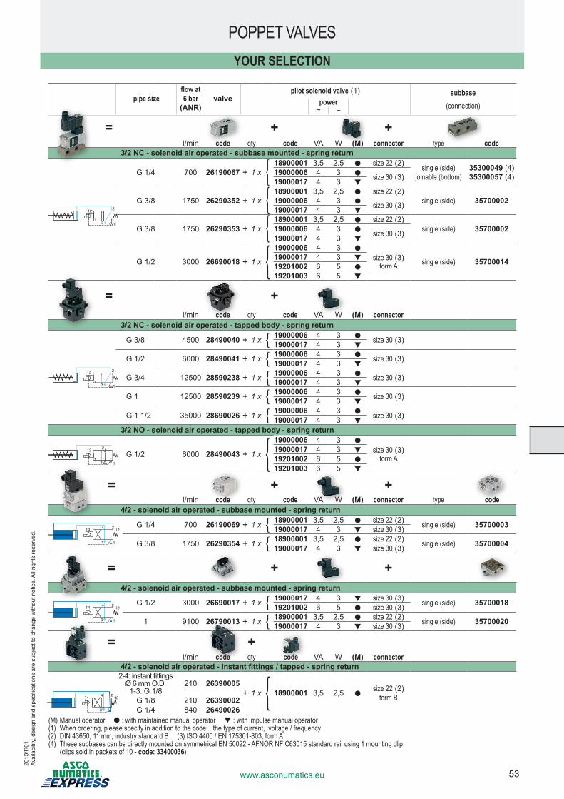
53www.asconumatics.eu
POPPET VALVES
pipe sizeflow at 6 bar
(ANR)valve
pilot solenoid valve (1) subbase(connection)power
~ =
= + +l/min code qty code VA W (M) connector type code
3/2 NC - solenoid air operated - subbase mounted - spring return
G 1/4 700 26190067 + 1 x { 18900001 3,5 2,5 ● size 22 (2) single (side)joinable (bottom)
35300049 (4)35300057 (4)19000006 4 3 ● size 30 (3)19000017 4 3 ▼
G 3/8 1750 26290352 + 1 x { 18900001 3,5 2,5 ● size 22 (2) single (side) 3570000219000006 4 3 ● size 30 (3)19000017 4 3 ▼
G 3/8 1750 26290353 + 1 x { 18900001 3,5 2,5 ● size 22 (2) single (side) 3570000219000006 4 3 ● size 30 (3)19000017 4 3 ▼
G 1/2 3000 26690018 + 1 x { 19000006 4 3 ●
size 30 (3) form A single (side) 3570001419000017 4 3 ▼
19201002 6 5 ●19201003 6 5 ▼
= +l/min code qty code VA W (M) connector
3/2 NC - solenoid air operated - tapped body - spring return
G 3/8 4500 28490040 + 1 x { 19000006 4 3 ● size 30 (3)19000017 4 3 ▼
G 1/2 6000 28490041 + 1 x { 19000006 4 3 ● size 30 (3)19000017 4 3 ▼
G 3/4 12500 28590238 + 1 x { 19000006 4 3 ● size 30 (3)19000017 4 3 ▼
G 1 12500 28590239 + 1 x { 19000006 4 3 ● size 30 (3)19000017 4 3 ▼
G 1 1/2 35000 28690026 + 1 x { 19000006 4 3 ● size 30 (3)19000017 4 3 ▼
YOUR SELECTION
= + +l/min code qty code VA W (M) connector type code
4/2 - solenoid air operated - subbase mounted - spring return
2
3
14 412
1
G 1/4 700 26190069 + 1 x { 18900001 3,5 2,5 ● size 22 (2) single (side) 3570000319000017 4 3 ▼ size 30 (3)
G 3/8 1750 26290354 + 1 x { 18900001 3,5 2,5 ● size 22 (2) single (side) 3570000419000017 4 3 ▼ size 30 (3)
= + +4/2 - solenoid air operated - subbase mounted - spring return
2
3
14 412
1
G 1/2 3000 26690017 + 1 x { 19000017 4 3 ▼ size 30 (3) single (side) 3570001819201002 6 5 ● size 30 (3)
1 9100 26790013 + 1 x { 18900001 3,5 2,5 ● size 22 (2) single (side) 3570002019000017 4 3 ▼ size 30 (3)
= +l/min code qty code VA W (M) connector
4/2 - solenoid air operated - instant fittings / tapped - spring return2-4: instant fittings
Ø 6 mm O.D. 1-3: G 1/8
210 26390005+ 1 x { 18900001 3,5 2,5 ●
size 22 (2) form BG 1/8 210 26390002
G 1/4 840 26490026(M) Manual operator ● : with maintained manual operator ▼ : with impulse manual operator(1) When ordering, please specify in addition to the code: the type of current, voltage / frequency(2) DIN 43650, 11 mm, industry standard B (3) ISO 4400 / EN 175301-803, form A(4) These subbases can be directly mounted on symmetrical EN 50022 - AFNOR NF C63015 standard rail using 1 mounting clip (clips sold in packets of 10 - code: 33400036)
2
3
14 412
1
3/2 NO - solenoid air operated - tapped body - spring return
2
G 1/2 6000 28490043 + 1 x { 19000006 4 3 ●
size 30 (3) form A
19000017 4 3 ▼19201002 6 5 ●19201003 6 5 ▼
2013
/R01
Ava
ilabi
lity,
des
ign
and
spec
ifica
tions
are
sub
ject
to c
hang
e w
ithou
t not
ice.
All
right
s re
serv
ed.
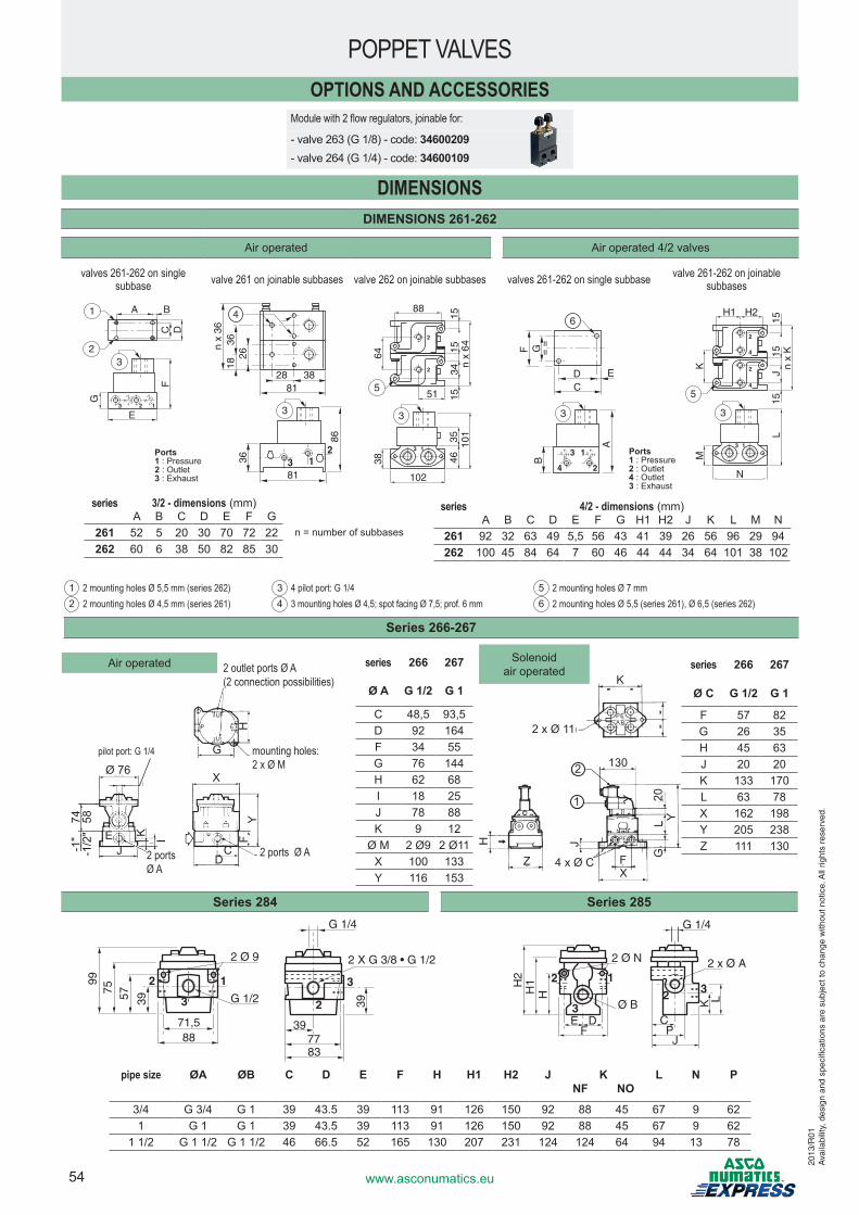
54 www.asconumatics.eu
series 3/2 - dimensions (mm)A B C D E F G
261 52 5 20 30 70 72 22262 60 6 38 50 82 85 30
series 4/2 - dimensions (mm)A B C D E F G H1 H2 J K L M N
261 92 32 63 49 5,5 56 43 41 39 26 56 96 29 94262 100 45 84 64 7 60 46 44 44 34 64 101 38 102
1 2 mounting holes Ø 5,5 mm (series 262)2 2 mounting holes Ø 4,5 mm (series 261)
3 4 pilot port: G 1/44 3 mounting holes Ø 4,5; spot facing Ø 7,5; prof. 6 mm
5 2 mounting holes Ø 7 mm6 2 mounting holes Ø 5,5 (series 261), Ø 6,5 (series 262)
n = number of subbases
Ports1 : Pressure2 : Outlet3 : Exhaust
DIMENSIONSDIMENSIONS 261-262
Air operated Air operated 4/2 valves
valves 261-262 on single subbase valve 261 on joinable subbases valve 262 on joinable subbases valves 261-262 on single subbase valve 261-262 on joinable
subbases
BA
DC
2
1
E
F
3
G
23 1
382881
81
4
3636
18n
x 36
26
3 12
86
3
64
88
n x
6415
3415
15
51
2
2
538 46
35 101
102
3 1
3
4
3 1
2
D EC
G ==
6
FB
A
3
K
H1 H2
n x
K15
J15
15
2
2
4
4
5
M
L
N
3 1
3
OPTIONS AND ACCESSORIESModule with 2 flow regulators, joinable for:
- valve 263 (G 1/8) - code: 34600209- valve 264 (G 1/4) - code: 34600109
Series 266-267
POPPET VALVES
pipe size ØA ØB C D E F H H1 H2 J KNF NO
L N P
3/4 G 3/4 G 1 39 43.5 39 113 91 126 150 92 88 45 67 9 621 G 1 G 1 39 43.5 39 113 91 126 150 92 88 45 67 9 62
1 1/2 G 1 1/2 G 1 1/2 46 66.5 52 165 130 207 231 124 124 64 94 13 78
2 ports Ø A
2 ports Ø A
2 ports Ø A
pilot port: G 1/4 mounting holes: 2 x Ø M
2 outlet ports Ø A(2 connection possibilities)
Ø 76
Y
H
74 58-1
"-1
/2" K I
JE
YF
X
CD Z F
X
J
4 x Ø C
GL
20
2 x Ø 11
K
130
A BPE
PE
2
1
H
Yseries 266 267
Ø A G 1/2 G 1
C 48,5 93,5D 92 164F 34 55G 76 144H 62 68I 18 25J 78 88K 9 12
Ø M 2 Ø9 2 Ø11X 100 133Y 116 153
Air operated Solenoid air operated series 266 267
Ø C G 1/2 G 1
F 57 82G 26 35H 45 63J 20 20K 133 170L 63 78X 162 198Y 205 238Z 111 130
Series 284 Series 285G 1/4
39
397783
G 1/2
2 Ø 9
9975 57 39
71,588
12
3 2
3
2 X G 3/8 • G 1/2 2 x Ø A
CP
J
G 1/4
K LH
H2
H1
Ø B
2 Ø N
E DF
1
3
2
2 3
U
U
P E
G
Ports1 : Pressure2 : Outlet4 : Outlet3 : Exhaust
2013
/R01
Ava
ilabi
lity,
des
ign
and
spec
ifica
tions
are
sub
ject
to c
hang
e w
ithou
t not
ice.
All
right
s re
serv
ed.
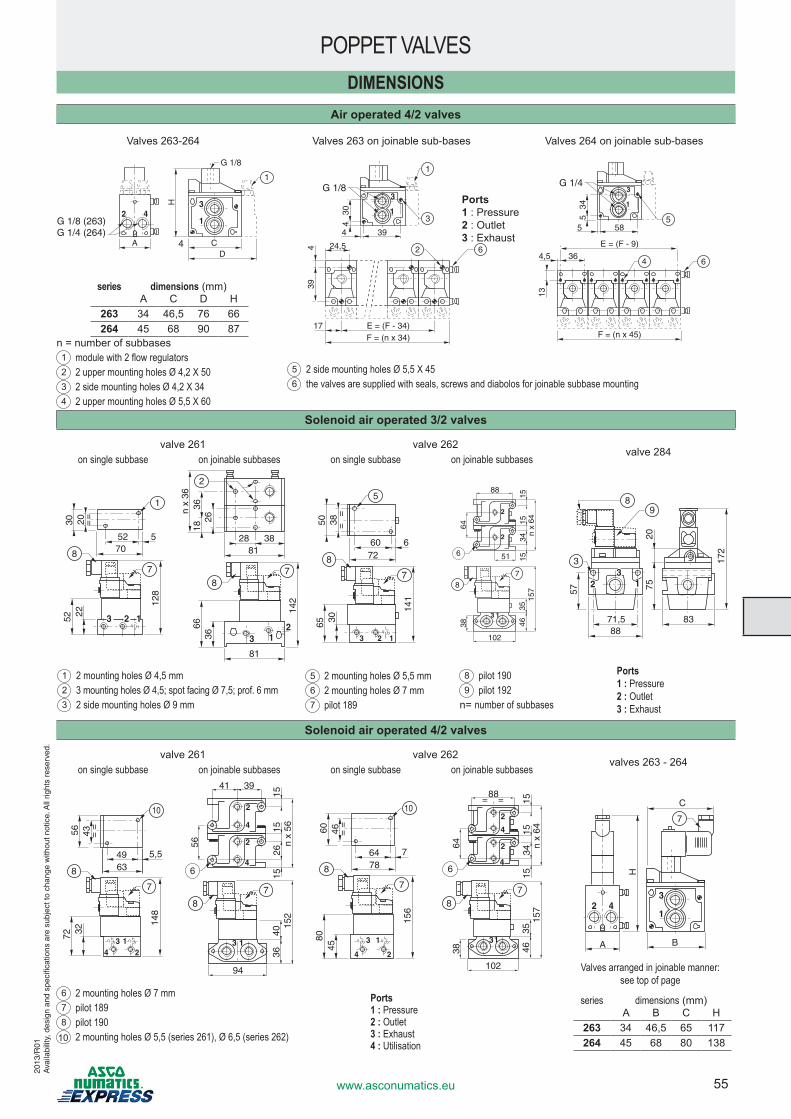
55www.asconumatics.eu
DIMENSIONSAir operated 4/2 valves
Valves 263-264 Valves 263 on joinable sub-bases Valves 264 on joinable sub-bases
2 43
1
CAD
H1
G 1/8
4
G 1/8 (263)G 1/4 (264)
1
3
E = (F - 34) 17 F = (n x 34)
24,5
304
39
4
394
6
3
2
1
G 1/8
6 4
5
E = (F - 9)
F = (n x 45)
13
36 4,5
58
345
5
1
3G 1/4
Solenoid air operated 3/2 valves
valve 261 valve 262valve 284
on single subbase on joinable subbases on single subbase on joinable subbases
2 13
52 570
20 ==
1
7
8
3052 22
128
382881
81
2
3666
3618
n x
36
26
3 12
142
78
3 2 1
60 672
38=
=
5
7
8
5065 30
141
64
88
n x
6415
3415
15
51
2
2
6
38 4635
157
102
3 1
78
8388
71,5
172
357 75
20
98
23
1
1 2 mounting holes Ø 4,5 mm2 3 mounting holes Ø 4,5; spot facing Ø 7,5; prof. 6 mm3 2 side mounting holes Ø 9 mm
5 2 mounting holes Ø 5,5 mm6 2 mounting holes Ø 7 mm7 pilot 189
8 pilot 1909 pilot 192
n = number of subbases
Solenoid air operated 4/2 valves
valve 261 valve 262valves 263 - 264
on single subbase on joinable subbases on single subbase on joinable subbases
43 1
2
49 5,563
43=
=
10
7
8
5672 32
148
3640
152
94
56
41 39
n x
5615
2615
15
4
4
2
2
6
78
3 14
3 1
2
64 778
46=
=
10
7
8
6080
45
156
64
88
n x
6415
3415
15
2
2
4
46
38 4635
157
102
31
78
= =
2 43
1
BA
H
C
7
POPPET VALVES
series dimensions (mm)A B C H
263 34 46,5 65 117264 45 68 80 138
Valves arranged in joinable manner: see top of page
Ports1 : Pressure2 : Outlet3 : Exhaust4 : Utilisation
n = number of subbases1 module with 2 flow regulators2 2 upper mounting holes Ø 4,2 X 503 2 side mounting holes Ø 4,2 X 344 2 upper mounting holes Ø 5,5 X 60
Ports1 : Pressure2 : Outlet3 : Exhaust
series dimensions (mm)A C D H
263 34 46,5 76 66264 45 68 90 87
5 2 side mounting holes Ø 5,5 X 456 the valves are supplied with seals, screws and diabolos for joinable subbase mounting
Ports1 : Pressure2 : Outlet3 : Exhaust
6 2 mounting holes Ø 7 mm7 pilot 1898 pilot 190
10 2 mounting holes Ø 5,5 (series 261), Ø 6,5 (series 262)
2013
/R01
Ava
ilabi
lity,
des
ign
and
spec
ifica
tions
are
sub
ject
to c
hang
e w
ithou
t not
ice.
All
right
s re
serv
ed.
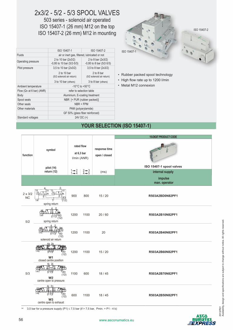
56 www.asconumatics.eu
YOUR SELECTION (ISO 15407-1)
2x3/2 - 5/2 - 5/3 SPOOL VALVES503 series - solenoid air operated
ISO 15407-1 (26 mm) M12 on the topISO 15407-2 (26 mm) M12 in mounting
ISO 15407-1 ISO 15407-2Fluids air or inert gas, filtered, lubricated or not
Operating pressure 2 to 10 bar (2x3/2)-0,95 to 10 bar (5/2-5/3)
2 to 8 bar (2x3/2)-0,95 to 8 bar (5/2-5/3)
Pilot pressure 3,5 to 10 bar (2x3/2) 3,5 to 8 bar (2x3/2)2 to 10 bar
(5/2 solenoid air return)2 to 8 bar
(5/2 solenoid air return)
3 to 10 bar (others) 3 to 8 bar (others)Ambient temperature -10°C to +50°CFlow (Qv at 6 bar) (ANR) refer to selection tableBody Aluminium, E-coating treatmentSpool seals NBR [+ PUR (rubber packed)]Other seals NBR + FPMOther materials PAM (polyarylamide)
GF 50% (glass fiber reinforced)Standard voltages 24V DC (=)
• Rubber packed spool technology• High flow rate up to 1200 l/min• Metal M12 connexion
ISO 15407-1
ISO 15407-2
functionsymbol
rated flow
at 6,3 barl/min (ANR)
response time
open / closed
15-DIGIT PRODUCT CODE
pilot (14)return (12)
ISO 15407-1 spool valves1 21 4
2 34 5 (ms) internal supply
impulseman. operator
2 x 3/2NC
14 1210 10
83(12)14
5
4
3
2
1spring return
900 800 15 / 20 R503A2BD0N82PF1
5/2
1
4 2
3514 83(12)
spring return
1200 1100 20 / 60 R503A2B10N82PF1
1
4 2
3514(12)83
solenoid air return
1200 1100 20 R503A2B40N82PF1
5/3
1
4 2
3514(12)83
W1closed centre position
1200 1100 15 / 20 R503A2B60N82PF1
1
4 2
3514(12)83
W2centre open to pressure
1100 600 18 / 45 R503A2B70N82PF1
1
4 2
3514(12)83
W3centre open to exhaust
600 1100 18 / 45 R503A2B50N82PF1
(a) 3,5 bar for a pressure supply (P1) ≤ 7,5 bar (if > 7,5 bar, Pmin. = P1 - 4 b)
0141
9GB
-201
2/R
01Av
aila
bilit
y, d
esig
n an
d sp
ecifi
catio
ns a
re s
ubje
ct to
cha
nge
with
out n
otic
e. A
ll rig
hts
rese
rved
.
2013
/R01
Ava
ilabi
lity,
des
ign
and
spec
ifica
tions
are
sub
ject
to c
hang
e w
ithou
t not
ice.
All
right
s re
serv
ed.
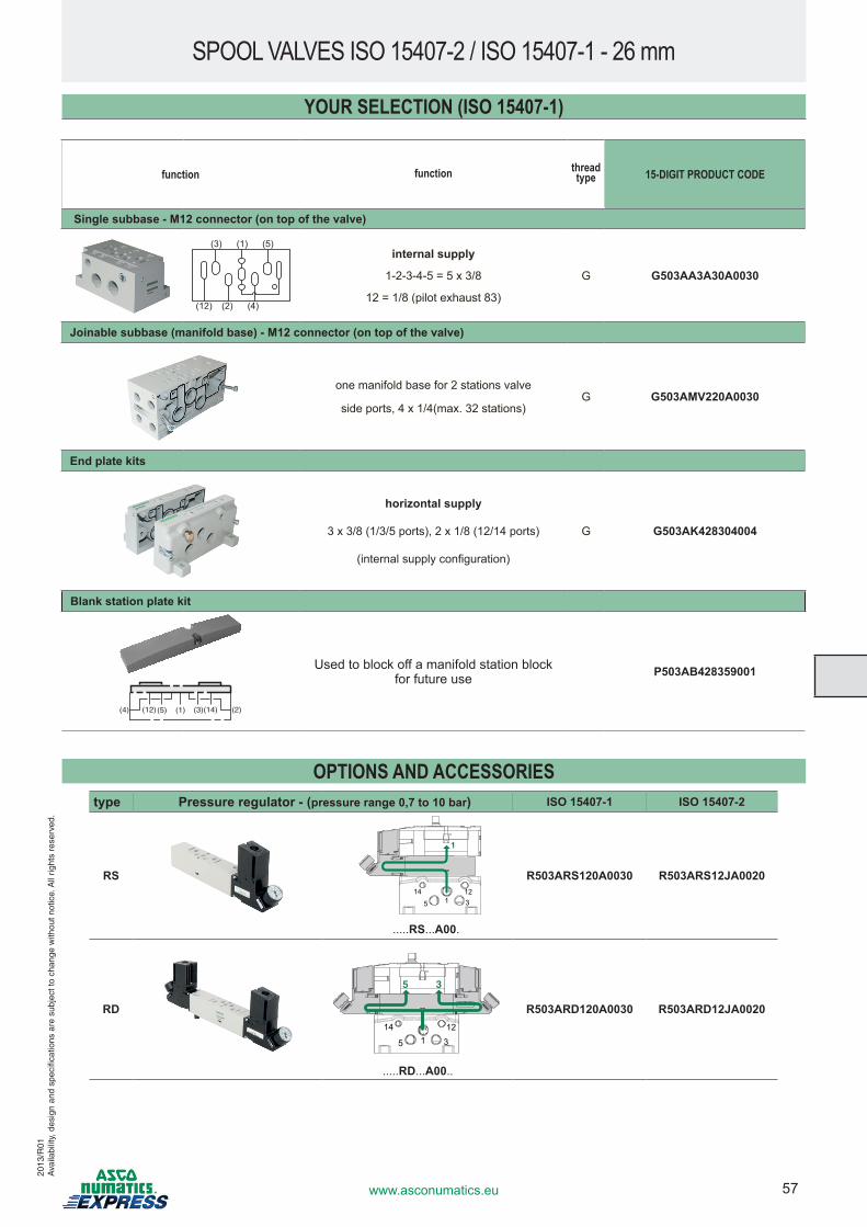
57www.asconumatics.eu
SPOOL VALVES ISO 15407-2 / ISO 15407-1 - 26 mm
function function thread type 15-DIGIT PRODUCT CODE
Single subbase - M12 connector (on top of the valve)
(3) (1) (5)
(12) (2) (4)
internal supply
1-2-3-4-5 = 5 x 3/8
12 = 1/8 (pilot exhaust 83)
G G503AA3A30A0030
Joinable subbase (manifold base) - M12 connector (on top of the valve)
one manifold base for 2 stations valve
side ports, 4 x 1/4(max. 32 stations)G G503AMV220A0030
End plate kits
horizontal supply
3 x 3/8 (1/3/5 ports), 2 x 1/8 (12/14 ports)
(internal supply configuration)
G G503AK428304004
Blank station plate kit
(5) (1) (3)(4) (2)(12) (14)
Used to block off a manifold station block for future use P503AB428359001
YOUR SELECTION (ISO 15407-1)
OPTIONS AND ACCESSORIEStype Pressure regulator - (pressure range 0,7 to 10 bar) ISO 15407-1 ISO 15407-2
RS
1
14
5 1 312
.....RS...A00.
R503ARS120A0030 R503ARS12JA0020
RD
5 3
14
5 1 3
12
.....RD...A00..
R503ARD120A0030 R503ARD12JA0020
2013
/R01
Ava
ilabi
lity,
des
ign
and
spec
ifica
tions
are
sub
ject
to c
hang
e w
ithou
t not
ice.
All
right
s re
serv
ed.
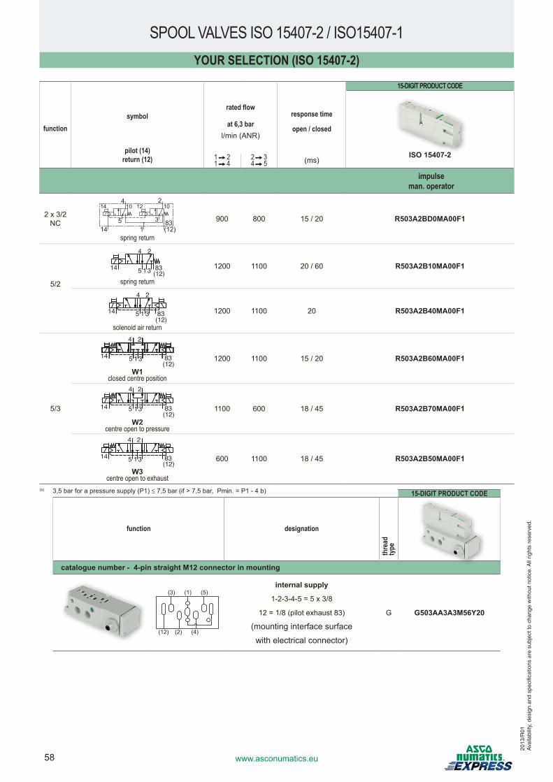
58 www.asconumatics.eu
15-DIGIT PRODUCT CODE
function designation
thre
ad
type
catalogue number - 4-pin straight M12 connector in mounting
(3) (1) (5)
(12) (2) (4)
internal supply
1-2-3-4-5 = 5 x 3/8
12 = 1/8 (pilot exhaust 83)
(mounting interface surface
with electrical connector)
G G503AA3A3M56Y20
YOUR SELECTION (ISO 15407-2)
15-DIGIT PRODUCT CODE
functionsymbol
rated flow
at 6,3 barl/min (ANR)
response time
open / closed
ISO 15407-2pilot (14)return (12) 1 2
1 42 34 5 (ms)
impulseman. operator
2 x 3/2NC
14 1210 10
83(12)14
5
4
3
2
1spring return
900 800 15 / 20 R503A2BD0MA00F1
5/2
1
4 2
3514 83(12)
spring return
1200 1100 20 / 60 R503A2B10MA00F1
1
4 2
3514(12)83
solenoid air return
1200 1100 20 R503A2B40MA00F1
5/3
1
4 2
3514(12)83
W1closed centre position
1200 1100 15 / 20 R503A2B60MA00F1
1
4 2
3514(12)83
W2centre open to pressure
1100 600 18 / 45 R503A2B70MA00F1
1
4 2
3514(12)83
W3centre open to exhaust
600 1100 18 / 45 R503A2B50MA00F1
(a) 3,5 bar for a pressure supply (P1) ≤ 7,5 bar (if > 7,5 bar, Pmin. = P1 - 4 b)
SPOOL VALVES ISO 15407-2 / ISO15407-1
2013
/R01
Ava
ilabi
lity,
des
ign
and
spec
ifica
tions
are
sub
ject
to c
hang
e w
ithou
t not
ice.
All
right
s re
serv
ed.
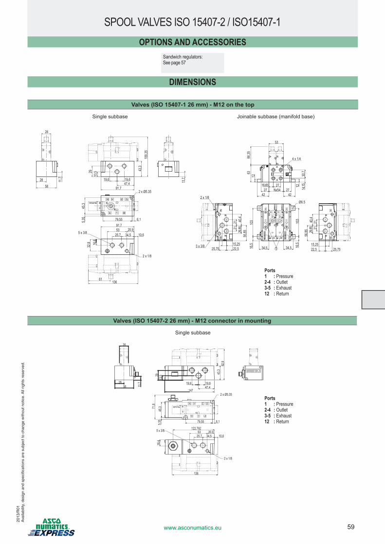
59www.asconumatics.eu
Valves (ISO 15407-2 26 mm) - M12 connector in mounting
Single subbase
45,3
5,35 6,179,55
71,6
2856
26
43,3
92,9
19,6 19,647,4
13,529
147
136
10,634,525,753
122,79220,9
18,4
11,7
2 x Ø5.35
2 x 1/8
5 x 3/8
SPOOL VALVES ISO 15407-2 / ISO15407-1
Valves (ISO 15407-1 26 mm) - M12 on the top
Single subbase Joinable subbase (manifold base)
45,3
5,35 6,179,55
109,3
5
16,6
32,8
5325,7
11,7
91,7
136
13,529
19,619,6
56
26
28 11,7
34,520,9
10,6
61
43,3
47,491,7
2 x Ø5.35
2 x 1/8
5 x 3/8
Nx5427 2742 42
1263
66,35
16,65 27
14,15
30,7
12
103 103
16,5 16,5
34,5 34,522,515,25
25,75
2121 40
,429
,8556
,85
56,85
212140
,429
,85
22,515,25
25,75
53
1
Ø6.5
4 x 1/4
2 x 1/8
3 x 3/8
Ports1 : Pressure2-4 : Outlet3-5 : Exhaust12 : Return
DIMENSIONS
OPTIONS AND ACCESSORIESSandwich regulators:See page 57
2013
/R01
Ava
ilabi
lity,
des
ign
and
spec
ifica
tions
are
sub
ject
to c
hang
e w
ithou
t not
ice.
All
right
s re
serv
ed.
Ports1 : Pressure2-4 : Outlet3-5 : Exhaust12 : Return
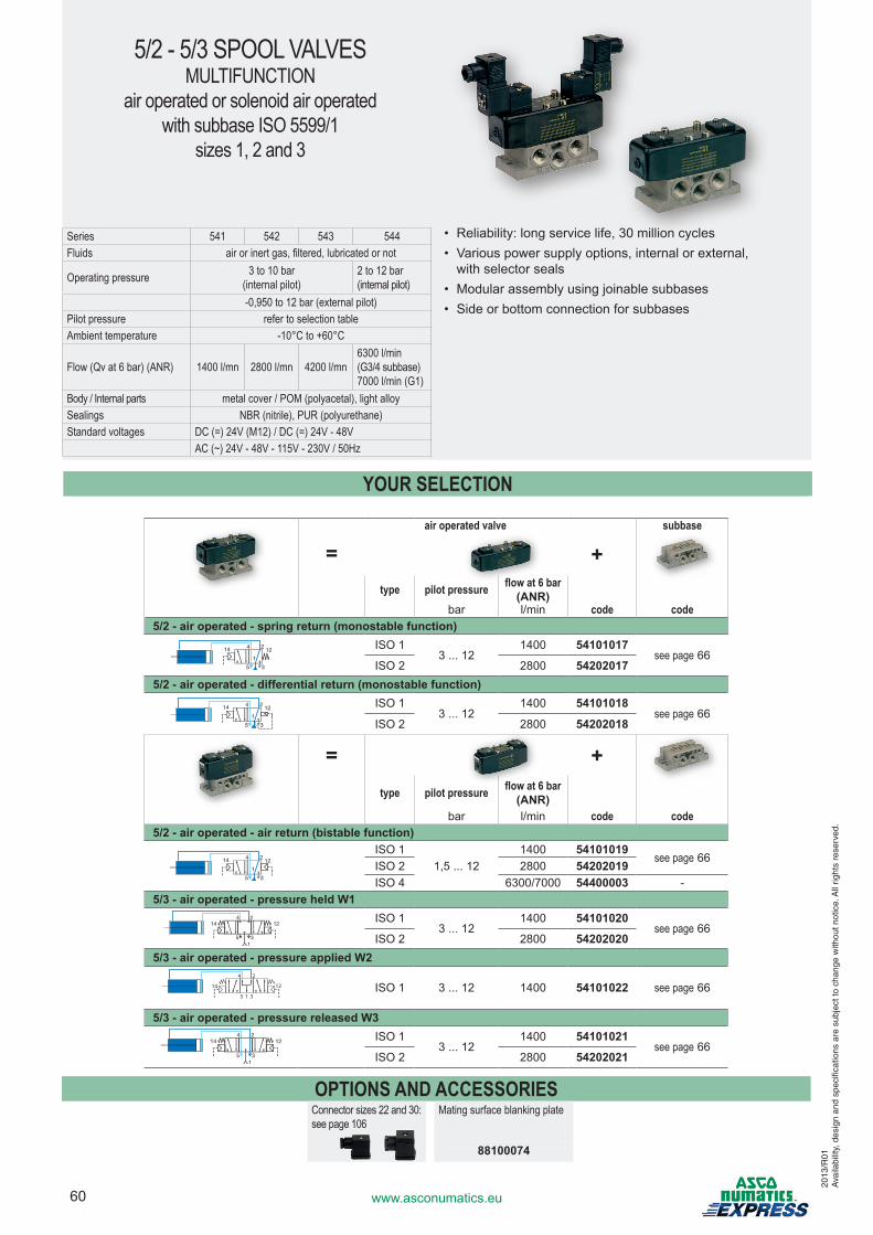
60 www.asconumatics.eu
5/2 - 5/3 SPOOL VALVESMULTIFUNCTION
air operated or solenoid air operatedwith subbase ISO 5599/1
sizes 1, 2 and 3
air operated valve subbase
=type pilot pressure flow at 6 bar
(ANR)bar l/min code code
5/2 - air operated - spring return (monostable function)ISO 1
3 ... 121400 54101017
see page 66ISO 2 2800 54202017
5/2 - air operated - differential return (monostable function)ISO 1
3 ... 121400 54101018
see page 66ISO 2 2800 54202018
=type pilot pressure flow at 6 bar
(ANR)bar l/min code code
5/2 - air operated - air return (bistable function)ISO 1
1,5 ... 121400 54101019
see page 66ISO 2 2800 54202019ISO 4 6300/7000 54400003 -
5/3 - air operated - pressure held W1ISO 1
3 ... 121400 54101020
see page 66ISO 2 2800 54202020
5/3 - air operated - pressure applied W224
35
14 12
1ISO 1 3 ... 12 1400 54101022 see page 66
5/3 - air operated - pressure released W3ISO 1
3 ... 121400 54101021
see page 66ISO 2 2800 54202021
OPTIONS AND ACCESSORIESConnector sizes 22 and 30: see page 106
Mating surface blanking plate
88100074
Series 541 542 543 544Fluids air or inert gas, filtered, lubricated or not
Operating pressure 3 to 10 bar(internal pilot)
2 to 12 bar(internal pilot)
-0,950 to 12 bar (external pilot)Pilot pressure refer to selection tableAmbient temperature -10°C to +60°C
Flow (Qv at 6 bar) (ANR) 1400 l/mn 2800 l/mn 4200 l/mn6300 l/min (G3/4 subbase)7000 l/min (G1)
Body / Internal parts metal cover / POM (polyacetal), light alloySealings NBR (nitrile), PUR (polyurethane)Standard voltages DC (=) 24V (M12) / DC (=) 24V - 48V AC (~) 24V - 48V - 115V - 230V / 50Hz
• Reliability: long service life, 30 million cycles• Various power supply options, internal or external,
with selector seals• Modular assembly using joinable subbases• Side or bottom connection for subbases
YOUR SELECTION
+
+
2013
/R01
Ava
ilabi
lity,
des
ign
and
spec
ifica
tions
are
sub
ject
to c
hang
e w
ithou
t not
ice.
All
right
s re
serv
ed.
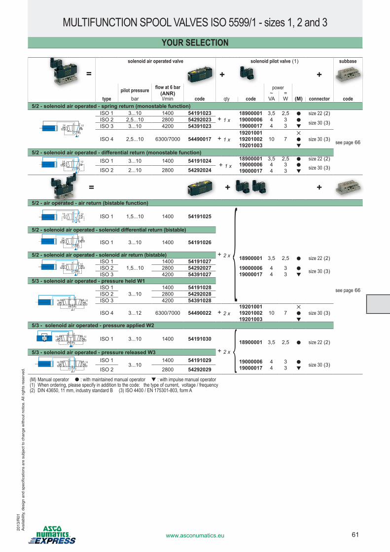
61www.asconumatics.eu
solenoid air operated valve solenoid pilot valve (1) subbase
+ +pilot pressure flow at 6 bar
(ANR)power
~ =type bar l/min code qty code VA W (M) connector code
5/2 - solenoid air operated - spring return (monostable function)
2
35
14 412
1
ISO 1 3...10 1400 54191023+ 1 x
18900001 3,5 2,5 ● size 22 (2)
see page 66
ISO 2 2,5...10 2800 54292023 1900000619000017
44
33
●▼
size 30 (3)ISO 3 3...10 4200 54391023
ISO 4 2,5...10 6300/7000 54490017 + 1 x192010011920100219201003
10 7✕ ●▼
size 30 (3)
5/2 - solenoid air operated - differential return (monostable function)2
35
14 412
1
ISO 1 3...10 1400 54191024+ 1 x
18900001 3,5 2,5 ● size 22 (2)1900000619000017
44
33
●▼
size 30 (3)ISO 2 2...10 2800 54292024
= + +5/2 - air operated - air return (bistable function)
ISO 1 1,5...10 1400 54191025
+ 2 x
see page 66
5/2 - solenoid air operated - solenoid differential return (bistable)2
35
14 4
1
12
ISO 1 3...10 1400 54191026
5/2 - solenoid air operated - solenoid air return (bistable) 18900001 3,5 2,5 ● size 22 (2)2
35
14 412
1
ISO 11,5...10
1400 54191027ISO 2 2800 54292027 19000006
1900001744
33
●▼
size 30 (3)ISO 3 4200 543910275/3 - solenoid air operated - pressure held W1
24
35
14 12
1
ISO 13...10
1400 54191028ISO 2 2800 54292028ISO 3 4200 54391028
ISO 4 3...12 6300/7000 54490022 + 2 x192010011920100219201003
10 7✕ ●▼
size 30 (3)
5/3 - solenoid air operated - pressure applied W2
ISO 1 3...10 1400 54191030
+ 2 x
18900001 3,5 2,5 ● size 22 (2)
5/3 - solenoid air operated - pressure released W324
35
14 12
1
ISO 13...10
1400 54191029 1900000619000017
44
33
●▼
size 30 (3)ISO 2 2800 54292029
(M) Manual operator ● : with maintained manual operator ▼ : with impulse manual operator(1) When ordering, please specify in addition to the code: the type of current, voltage / frequency(2) DIN 43650, 11 mm, industry standard B (3) ISO 4400 / EN 175301-803, form A
MULTIFUNCTION SPOOL VALVES ISO 5599/1 - sizes 1, 2 and 3YOUR SELECTION
=
2013
/R01
Ava
ilabi
lity,
des
ign
and
spec
ifica
tions
are
sub
ject
to c
hang
e w
ithou
t not
ice.
All
right
s re
serv
ed.
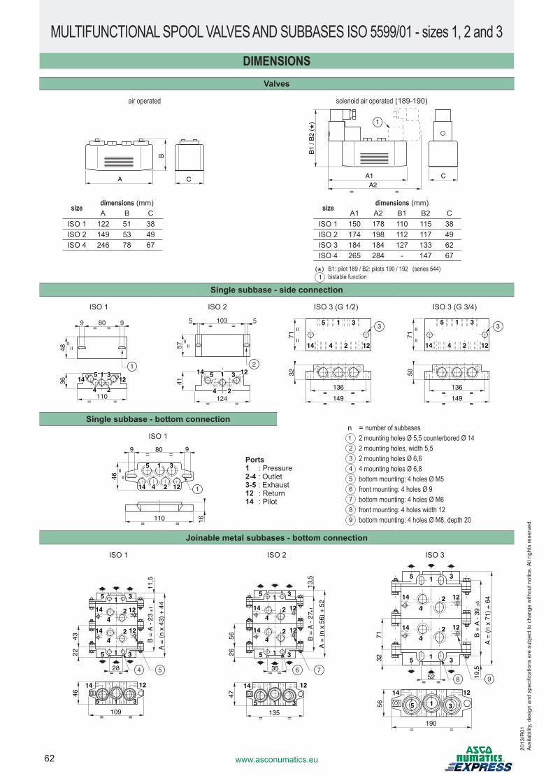
62 www.asconumatics.eu
DIMENSIONSValves
air operated solenoid air operated (189-190)
A C
B
A1A2
= =
C
B1
/ B2
( *) 1
Single subbase - side connection
ISO 1 ISO 2 ISO 3 (G 1/2) ISO 3 (G 3/4)
99 80= =
48=
=
36
110= =
1
14 125 1 3
4 2
5 3
55 103= =
57=
=
41
124= =
2
114 12
24 136
149= =
= =
71
1214
32
5 1 3
4 2
==
3
136
149= =
= =71
1214
50
5 1 3
4 2
==
3
Single subbase - bottom connection
ISO 1
809 9= =
=46=
110= = 16
114 4 122
5 1 3
Joinable metal subbases - bottom connection
ISO 1 ISO 2 ISO 3
46
B =
A -
23
±1
A =
(n
x 43
) +
44
11,5
4322
28= =
14
42 12
1 35
14
42 12
1 35
14 12
109= =
4 5
35 1
B =
A -
27 ±
1
A =
(n
x 56
) +
52
13,5
5626
35= =
47
14 12
14
42 12
35
144
2 12
35
135= =
6
1
1
7
315
A =
(n
x 71
) +
64
19,5
7132
52= =
14
42 12
1 35
14
42 12
1 35
56
190= =
5 1
14 12
3
8
B =
A -
39
±5
9
MULTIFUNCTIONAL SPOOL VALVES AND SUBBASES ISO 5599/01 - sizes 1, 2 and 3
size dimensions (mm)A1 A2 B1 B2 C
ISO 1 150 178 110 115 38ISO 2 174 198 112 117 49ISO 3 184 184 127 133 62ISO 4 265 284 - 147 67
(*) B1: pilot 189 / B2: pilots 190 / 192 (series 544)1 bistable function
size dimensions (mm)A B C
ISO 1 122 51 38ISO 2 149 53 49ISO 4 246 78 67
n = number of subbases1 2 mounting holes Ø 5,5 counterbored Ø 142 2 mounting holes, width 5,53 2 mounting holes Ø 6,64 4 mounting holes Ø 6,85 bottom mounting: 4 holes Ø M56 front mounting: 4 holes Ø 97 bottom mounting: 4 holes Ø M68 front mounting: 4 holes width 129 bottom mounting: 4 holes Ø M8, depth 20
Ports1 : Pressure2-4 : Outlet3-5 : Exhaust12 : Return14 : Pilot
2013
/R01
Ava
ilabi
lity,
des
ign
and
spec
ifica
tions
are
sub
ject
to c
hang
e w
ithou
t not
ice.
All
right
s re
serv
ed.
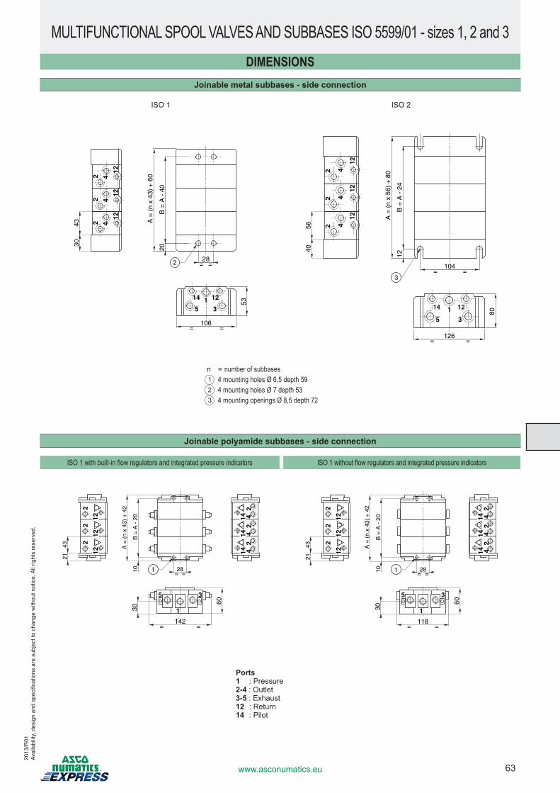
63www.asconumatics.eu
DIMENSIONSJoinable metal subbases - side connection
ISO 1 ISO 2
53
106= =
= =
4330
B =
A -
40
20
A =
(n
x 43
) +
60
2
35
12114
42
12
42
12
42
12
28
80
126
5640
104
B =
A -
24
12
A =
(n
x 56
) +
80
1
35
42
12
42
12
42
12
3
14 12
= =
= =
Joinable polyamide subbases - side connection
ISO 1 with built-in flow regulators and integrated pressure indicators ISO 1 without flow regulators and integrated pressure indicators
142= =
= =
30
60
1
2810
A =
(n
x 43
) +
42
B =
A -
20
2143 2
22
35
1
1212
12
44
22
214
1414
4
118= =
= =
30
60
1
28
A =
(n
x 43
) +
42
B =
A -
20
10
2143 2
22
35
1
1212
12
44
22
214
1414
4
n = number of subbases1 4 mounting holes Ø 6,5 depth 592 4 mounting holes Ø 7 depth 533 4 mounting openings Ø 8,5 depth 72
MULTIFUNCTIONAL SPOOL VALVES AND SUBBASES ISO 5599/01 - sizes 1, 2 and 3
Ports1 : Pressure2-4 : Outlet3-5 : Exhaust12 : Return14 : Pilot
2013
/R01
Ava
ilabi
lity,
des
ign
and
spec
ifica
tions
are
sub
ject
to c
hang
e w
ithou
t not
ice.
All
right
s re
serv
ed.
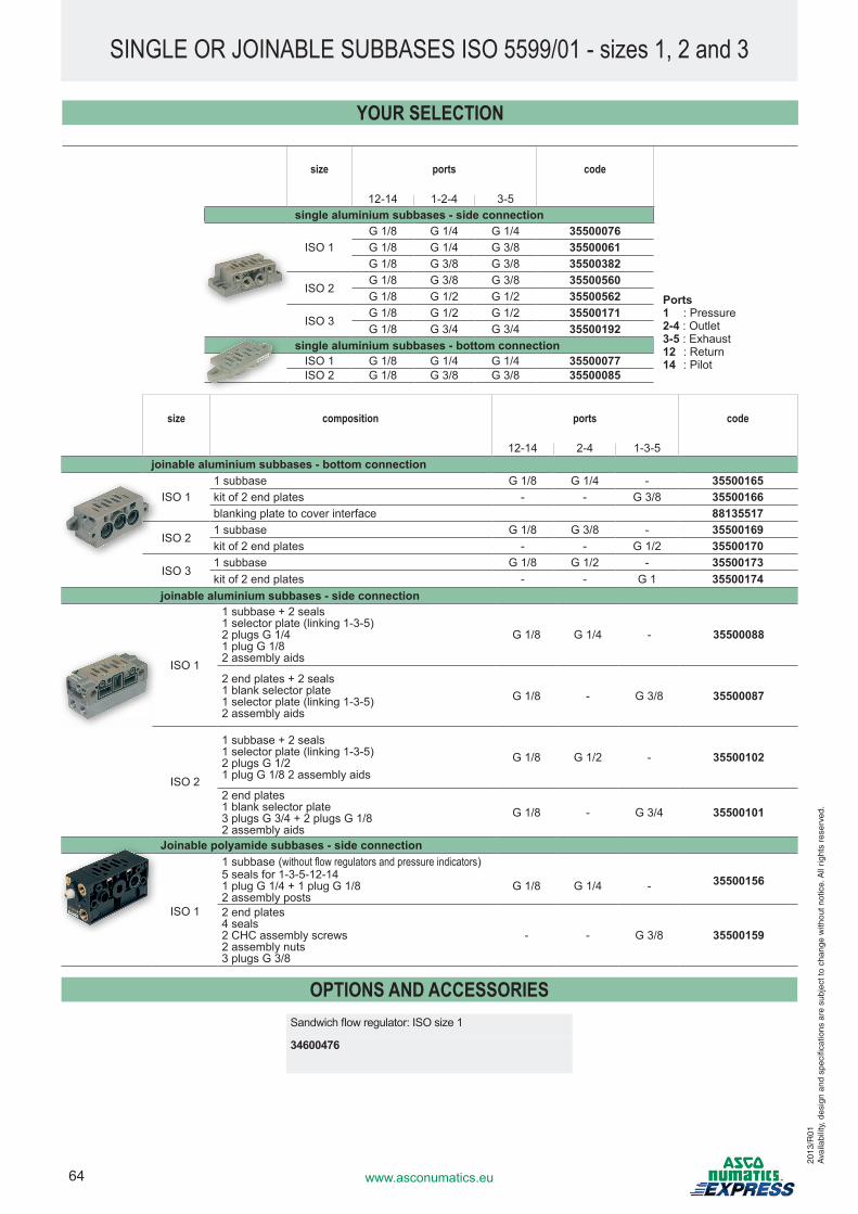
64 www.asconumatics.eu
SINGLE OR JOINABLE SUBBASES ISO 5599/01 - sizes 1, 2 and 3
size ports code
12-14 1-2-4 3-5single aluminium subbases - side connection
ISO 1G 1/8 G 1/4 G 1/4 35500076G 1/8 G 1/4 G 3/8 35500061G 1/8 G 3/8 G 3/8 35500382
ISO 2G 1/8 G 3/8 G 3/8 35500560G 1/8 G 1/2 G 1/2 35500562
ISO 3G 1/8 G 1/2 G 1/2 35500171G 1/8 G 3/4 G 3/4 35500192
single aluminium subbases - bottom connectionISO 1 G 1/8 G 1/4 G 1/4 35500077ISO 2 G 1/8 G 3/8 G 3/8 35500085
size composition ports code
12-14 2-4 1-3-5joinable aluminium subbases - bottom connection
ISO 11 subbase G 1/8 G 1/4 - 35500165kit of 2 end plates - - G 3/8 35500166blanking plate to cover interface 88135517
ISO 21 subbase G 1/8 G 3/8 - 35500169kit of 2 end plates - - G 1/2 35500170
ISO 31 subbase G 1/8 G 1/2 - 35500173kit of 2 end plates - - G 1 35500174
joinable aluminium subbases - side connection
ISO 1
1 subbase + 2 seals 1 selector plate (linking 1-3-5) 2 plugs G 1/4 1 plug G 1/8 2 assembly aids
G 1/8 G 1/4 - 35500088
2 end plates + 2 seals 1 blank selector plate 1 selector plate (linking 1-3-5) 2 assembly aids
G 1/8 - G 3/8 35500087
ISO 2
1 subbase + 2 seals 1 selector plate (linking 1-3-5) 2 plugs G 1/2 1 plug G 1/8 2 assembly aids
G 1/8 G 1/2 - 35500102
2 end plates 1 blank selector plate 3 plugs G 3/4 + 2 plugs G 1/8 2 assembly aids
G 1/8 - G 3/4 35500101
Joinable polyamide subbases - side connection
ISO 1
1 subbase (without flow regulators and pressure indicators)355001565 seals for 1-3-5-12-14
1 plug G 1/4 + 1 plug G 1/8 2 assembly posts
G 1/8 G 1/4 -
2 end plates 4 seals 2 CHC assembly screws 2 assembly nuts 3 plugs G 3/8
- - G 3/8 35500159
OPTIONS AND ACCESSORIESSandwich flow regulator: ISO size 1
34600476
Ports1 : Pressure2-4 : Outlet3-5 : Exhaust12 : Return14 : Pilot
YOUR SELECTION
2013
/R01
Ava
ilabi
lity,
des
ign
and
spec
ifica
tions
are
sub
ject
to c
hang
e w
ithou
t not
ice.
All
right
s re
serv
ed.
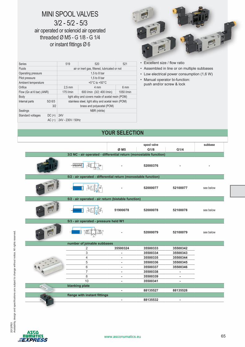
65www.asconumatics.eu
MINI SPOOL VALVES 3/2 - 5/2 - 5/3
air operated or solenoid air operatedthreaded Ø M5 - G 1/8 - G 1/4
or instant fittings Ø 6
spool valve subbaseØ M5 G1/8 G1/4
3/2 NC - air operated - differential return (monostable function)
- 52000376 - -
5/2 - air operated - differential return (monostable function)
- 52000077 52100077 see below
5/2 - air operated - air return (bistable function)
51900078 52000078 52100078 see below
5/3 - air operated - pressure held W1
- 52000079 52100079 see below
number of joinable subbases2 35500324 35500333 355003423 - 35500334 355003434 - 35500335 355003445 - 35500336 355003456 - 35500337 355003467 - 35500338 -8 - 35500339 -
10 - 35500341 -blanking plate
- 88135527 88135528flange with instant fittings
- 88135532 -
Series 519 520 521Fluids air or inert gas, filtered, lubricated or notOperating pressure 1,5 to 8 barPilot pressure 1,5 to 8 barAmbient temperature +5°C to +50°COrifice 2,5 mm 4 mm 6 mmFlow (Qv at 6 bar) (ANR) 175 l/min 600 l/min (3/2: 400 l/min) 1050 l/min Body light alloy and covers made of acetal resin (POM)Internal parts 5/2-5/3 stainless steel, light alloy and acetal resin (POM) 3/2 brass and polyacetal (POM)Sealings NBR (nitrile)Standard voltages DC (=) 24V AC (~) 24V - 230V / 50Hz
• Excellent size / flow ratio• Assembled in line or on multiple subbases• Low electrical power consumption (1,6 W)• Manual operator bi-function:
push and/or screw & lock
YOUR SELECTION
2013
/R01
Ava
ilabi
lity,
des
ign
and
spec
ifica
tions
are
sub
ject
to c
hang
e w
ithou
t not
ice.
All
right
s re
serv
ed.
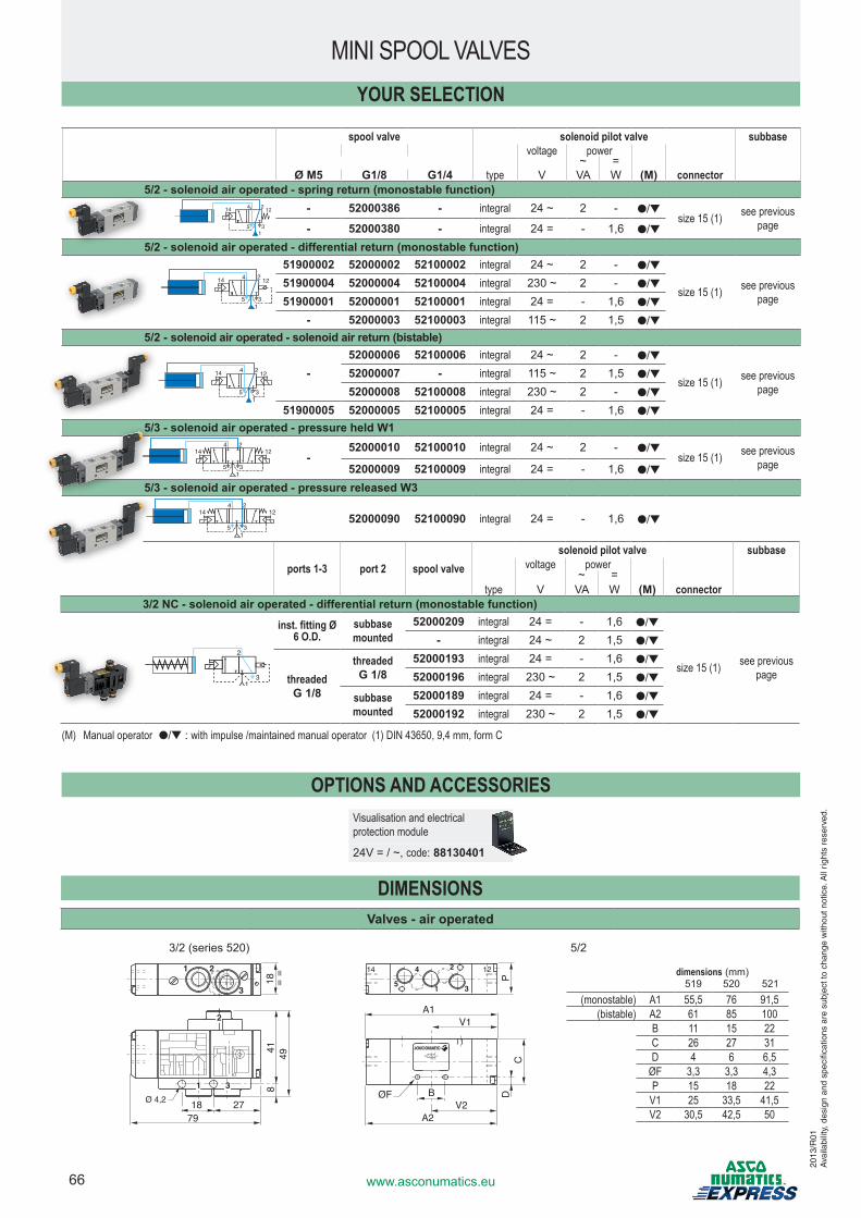
66 www.asconumatics.eu
DIMENSIONSValves - air operated
3/2 (series 520) 5/2
1 2
3
2
31
Ø 4,2
18=
=41
849
18 2779
14
51
4 2
3
12
DC
V1A1
A2V2
ØF
P
B
dimensions (mm)519 520 521
(monostable) A1 55,5 76 91,5(bistable) A2 61 85 100
B 11 15 22C 26 27 31D 4 6 6,5
ØF 3,3 3,3 4,3P 15 18 22
V1 25 33,5 41,5V2 30,5 42,5 50
spool valve solenoid pilot valve subbasevoltage power
~ =Ø M5 G1/8 G1/4 type V VA W (M) connector
5/2 - solenoid air operated - spring return (monostable function)2
35
14 412
1
- 52000386 - integral 24 ~ 2 - ●/▼size 15 (1) see previous
page- 52000380 - integral 24 = - 1,6 ●/▼5/2 - solenoid air operated - differential return (monostable function)
2
35
14 412
1
51900002 52000002 52100002 integral 24 ~ 2 - ●/▼
size 15 (1) see previous page
51900004 52000004 52100004 integral 230 ~ 2 - ●/▼51900001 52000001 52100001 integral 24 = - 1,6 ●/▼
- 52000003 52100003 integral 115 ~ 2 1,5 ●/▼5/2 - solenoid air operated - solenoid air return (bistable)
2
35
14 412
1
-52000006 52100006 integral 24 ~ 2 - ●/▼
size 15 (1) see previous page
52000007 - integral 115 ~ 2 1,5 ●/▼52000008 52100008 integral 230 ~ 2 - ●/▼
51900005 52000005 52100005 integral 24 = - 1,6 ●/▼5/3 - solenoid air operated - pressure held W1
24
35
14 12
1
-52000010 52100010 integral 24 ~ 2 - ●/▼
size 15 (1) see previous page52000009 52100009 integral 24 = - 1,6 ●/▼
5/3 - solenoid air operated - pressure released W324
35
14 12
1
52000090 52100090 integral 24 = - 1,6 ●/▼
ports 1-3 port 2 spool valvesolenoid pilot valve subbase
voltage power~ =
type V VA W (M) connector3/2 NC - solenoid air operated - differential return (monostable function)
inst. fitting Ø 6 O.D.
subbase mounted
52000209 integral 24 = - 1,6 ●/▼
size 15 (1) see previous page
- integral 24 ~ 2 1,5 ●/▼
threadedG 1/8
threadedG 1/8
52000193 integral 24 = - 1,6 ●/▼52000196 integral 230 ~ 2 1,5 ●/▼
subbase mounted
52000189 integral 24 = - 1,6 ●/▼52000192 integral 230 ~ 2 1,5 ●/▼
(M) Manual operator ●/▼ : with impulse /maintained manual operator (1) DIN 43650, 9,4 mm, form C
MINI SPOOL VALVESYOUR SELECTION
OPTIONS AND ACCESSORIESVisualisation and electrical protection module
24V = / ~, code: 88130401
2013
/R01
Ava
ilabi
lity,
des
ign
and
spec
ifica
tions
are
sub
ject
to c
hang
e w
ithou
t not
ice.
All
right
s re
serv
ed.
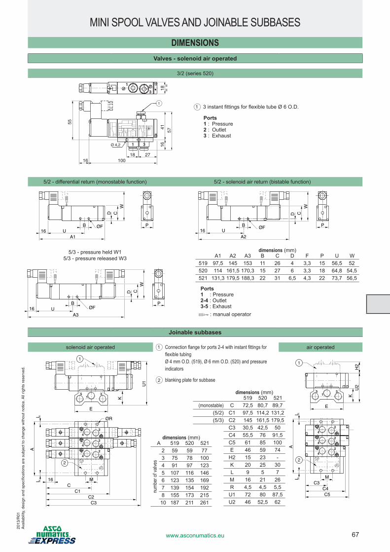
67www.asconumatics.eu
DIMENSIONSValves - solenoid air operated
3/2 (series 520)
1
3
57
4116
100162718
55
18=
=
1
Ø 4,2
2
1 3
5/2 - differential return (monostable function) 5/2 - solenoid air return (bistable function)
D CW
B ØF P
A116 U
D C
W
PB ØF
A216 U
5/3 - pressure held W15/3 - pressure released W3
D CW
PBØF
A316 U
Joinable subbases
solenoid air operated air operated
2
4
4
4
2
2
5 31
U1
K
C1C
C2C3
E
ØR
M16
AL
L
2
1
2
4
4
4
2
2
5 31
U2
H2
K
C4C3
C5
M
E
AL
L
2
1
MINI SPOOL VALVES AND JOINABLE SUBBASES
dimensions (mm)A1 A2 A3 B C D F P U W
519 97,5 145 153 11 26 4 3,3 15 56,5 52520 114 161,5 170,3 15 27 6 3,3 18 64,8 54,5521 131,3 179,5 188,3 22 31 6,5 4,3 22 73,7 56,5
dimensions (mm)A 519 520 521
numb
er of
valve
s
2 59 59 773 75 78 1004 91 97 1235 107 116 1466 123 135 1697 139 154 1928 155 173 215
10 187 211 261
dimensions (mm)519 520 521
(monostable) C 72,5 80,7 89,7(5/2) C1 97,5 114,2 131,2(5/3) C2 145 161,5 179,5
C3 30,5 42,5 50C4 55,5 76 91,5C5 61 85 100E 46 59 74
H2 15 23 -K 20 25 30L 9 5 7M 16 21 26R 4,5 4,5 5,5
U1 72 80 87,5U2 46 52,5 62
1 Connection flange for ports 2-4 with instant fittings for flexible tubing
Ø 4 mm O.D. (519), Ø 6 mm O.D. (520) and pressure indicators
2 blanking plate for subbase
Ports1 : Pressure2-4 : Outlet3-5 : Exhaust
: manual operator
Ports1 : Pressure2 : Outlet3 : Exhaust
1 3 instant fittings for flexible tube Ø 6 O.D.
2013
/R01
Ava
ilabi
lity,
des
ign
and
spec
ifica
tions
are
sub
ject
to c
hang
e w
ithou
t not
ice.
All
right
s re
serv
ed.
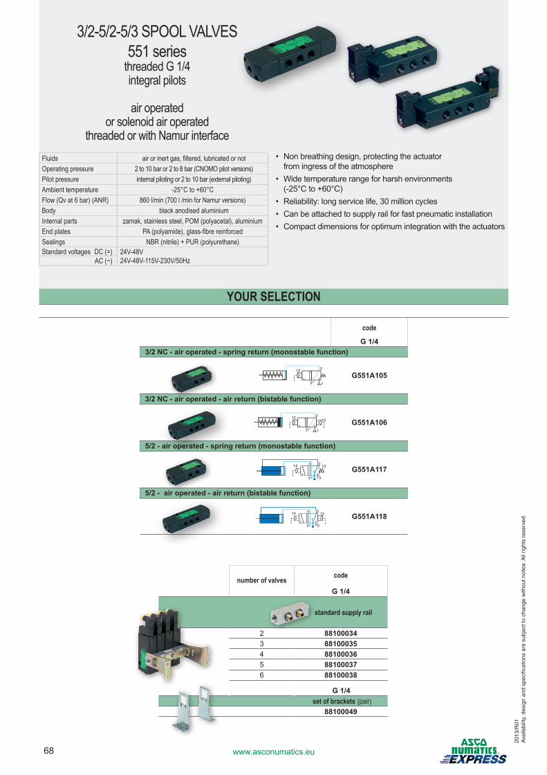
68 www.asconumatics.eu
3/2-5/2-5/3 SPOOL VALVES551 series
threaded G 1/4integral pilots
air operated or solenoid air operated
threaded or with Namur interfaceFluids air or inert gas, filtered, lubricated or notOperating pressure 2 to 10 bar or 2 to 8 bar (CNOMO pilot versions)Pilot pressure internal piloting or 2 to 10 bar (external piloting)Ambient temperature -25°C to +60°CFlow (Qv at 6 bar) (ANR) 860 l/min (700 l /min for Namur versions)Body black anodised aluminiumInternal parts zamak, stainless steel, POM (polyacetal), aluminiumEnd plates PA (polyamide), glass-fibre reinforcedSealings NBR (nitrile) + PUR (polyurethane)Standard voltages DC (=) 24V-48V
24V-48V-115V-230V/50Hz AC (~)
• Non breathing design, protecting the actuator from ingress of the atmosphere
• Wide temperature range for harsh environments (-25°C to +60°C)
• Reliability: long service life, 30 million cycles• Can be attached to supply rail for fast pneumatic installation• Compact dimensions for optimum integration with the actuators
code
G 1/43/2 NC - air operated - spring return (monostable function)
G551A105
3/2 NC - air operated - air return (bistable function)
10 G551A106
5/2 - air operated - spring return (monostable function)
G551A117
5/2 - air operated - air return (bistable function)
G551A118
number of valves code
G 1/4
standard supply rail
2 881000343 881000354 881000365 881000376 88100038
G 1/4set of brackets (pair)
88100049
YOUR SELECTION
2013
/R01
Ava
ilabi
lity,
des
ign
and
spec
ifica
tions
are
sub
ject
to c
hang
e w
ithou
t not
ice.
All
right
s re
serv
ed.
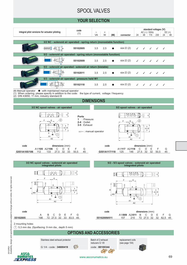
69www.asconumatics.eu
integral pilot versions for actuator piloting code(1)
standard voltages (V)~ = AC (~) / 50Hz DC (=)
VA W (M) connector 24 48 115 230 24 48
3/2 NC - solenoid air operated - spring return (monostable function)
55102005 3,5 2,5 ● size 22 (2) 3 3 3 3 3
5/2 - solenoid air operated - spring return (monostable function)2
35
14 412
1
55102009 3,5 2,5 ● size 22 (2) 3 3 3 3 3
5/2 - solenoid air operated - solenoid air return (bistable)2
35
14 412
1
55102011 3,5 2,5 ● size 22 (2) 3 3 3 3 3
5/3 - solenoid air operated - pressure held W124
35
14 12
1
55102118 3,5 2,5 ● size 22 (2) 3 3 3 3 3
(M) Manual operator ● : with maintained manual operator(1) When ordering, please specify in addition to the code: the type of current, voltage / frequency(2) DIN 43650, 11 mm, industry standard B
SPOOL VALVESYOUR SELECTION
OPTIONS AND ACCESSORIESStainless steel exhaust protector Batch of 2 exhaust
reducers G 1/8replacement coils(see page 104)
G 1/4 - code : 34600419 code : 88100344
DIMENSIONS3/2 NC spool valves - air operated 5/2 spool valves - air operated
123
3 1
22F E
D GC
A1A2
1
15 4 2 3
4
5 3
2
1
2
1
F E
D GC
A1A2
code dimensions (mm)A1/105 A2/106 C D E F G
G551A105/106 112 133 27,5 32 33 50,5 45
code dimensions (mm)A1/117 A2/118 C D E F G
G551A117/118 125 146 27,5 32 32 50,5 45
3/2 NC spool valves - solenoid air operated integrated pilots
5/2 - 5/3 spool valves - solenoid air operated integrated pilots
1 2 3
3 1
2
F E
B
D
G
C
A1
M5
A2
1
1 5 4 2 3
4
5 3
2
1 1
F E
B
D
G
C
A1 A2
M5
codeA B C D E F G
55102005 198 72 27,5 32 33 83,5 45
2 mounting holes:1 5,3 mm dia. (Spotfacing: 9 mm dia., depth 5 mm)
Ports1 : Pressure2-4 : Outlet3-5 : Exhaust
: manual operator
2013
/R01
Ava
ilabi
lity,
des
ign
and
spec
ifica
tions
are
sub
ject
to c
hang
e w
ithou
t not
ice.
All
right
s re
serv
ed.
code dimensions (mm)A1/009 A2/011 B C D E F G
55102009/011 157 210 72 27,5 32 32 82,5 45
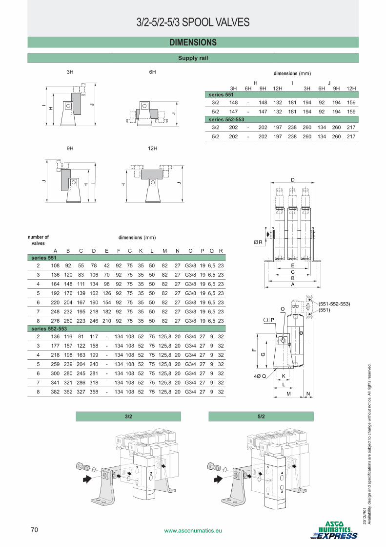
70 www.asconumatics.eu
DIMENSIONSSupply rail
3/2-5/2-5/3 SPOOL VALVES
2
3
1
2
4
5
3
1
dimensions (mm)
H I J3H 6H 9H 12H 3H 6H 9H 12H
series 5513/2 148 - 148 132 181 194 92 194 159
5/2 147 - 147 132 181 194 92 194 159series 552-553
3/2 202 - 202 197 238 260 134 260 217
5/2 202 - 202 197 238 260 134 260 217
number of valves
dimensions (mm)
A B C D E F G K L M N O P Q Rseries 551
2 108 92 55 78 42 92 75 35 50 82 27 G3/8 19 6,5 23
3 136 120 83 106 70 92 75 35 50 82 27 G3/8 19 6,5 23
4 164 148 111 134 98 92 75 35 50 82 27 G3/8 19 6,5 23
5 192 176 139 162 126 92 75 35 50 82 27 G3/8 19 6,5 23
6 220 204 167 190 154 92 75 35 50 82 27 G3/8 19 6,5 23
7 248 232 195 218 182 92 75 35 50 82 27 G3/8 19 6,5 23
8 276 260 223 246 210 92 75 35 50 82 27 G3/8 19 6,5 23series 552-553
2 136 116 81 117 - 134 108 52 75 125,8 20 G3/4 27 9 32
3 177 157 122 158 - 134 108 52 75 125,8 20 G3/4 27 9 32
4 218 198 163 199 - 134 108 52 75 125,8 20 G3/4 27 9 32
5 259 239 204 240 - 134 108 52 75 125,8 20 G3/4 27 9 32
6 300 280 245 281 - 134 108 52 75 125,8 20 G3/4 27 9 32
7 341 321 286 318 - 134 108 52 75 125,8 20 G3/4 27 9 32
8 382 362 327 358 - 134 108 52 75 125,8 20 G3/4 27 9 32
R
ECB
D
A
360°
°081
4Ø Q
M N
L
K
O
P
(551-552-553)(551)
F
G
3H 6H
J
H
I
J
9H 12H
J
H
I JH
3/2 5/2
2013
/R01
Ava
ilabi
lity,
des
ign
and
spec
ifica
tions
are
sub
ject
to c
hang
e w
ithou
t not
ice.
All
right
s re
serv
ed.
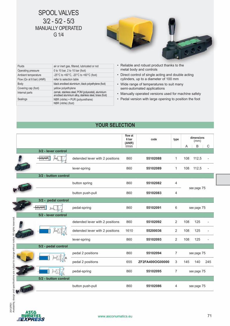
71www.asconumatics.eu
SPOOL VALVES3/2 - 5/2 - 5/3
MANUALLY OPERATEDG 1/4
Fluids air or inert gas, filtered, lubricated or notOperating pressure 0 to 10 bar, 2 to 10 bar (foot)Ambient temperature -25°C to +60°C, -20°C to +60°C (foot)Flow (Qv at 6 bar) (ANR) refer to selection tableBody black anodised aluminium, black polyethylene (foot)Covering cap (foot) yellow polyethyleneInternal parts zamak, stainless steel, POM (polyacetal), aluminium
anodised aluminium alloy, stainless steel, brass (foot)Sealings NBR (nitrile) + PUR (polyurethane)
NBR (nitrile) (foot)
flow at 6 bar
(ANR)code type dimensions
(mm)
l/min A B C3/2 - lever control
detended lever with 2 positions 860 55102088 1 108 112,5 -
lever-spring 860 55102089 1 108 112,5 -
3/2 - button control
button spring 860 55102082 4see page 75
button push-pull 860 55102083 4
3/2 - pedal control
pedal-spring 860 55102091 6 see page 75
5/2 - lever control
detended lever with 2 positions 860 55102092 2 108 125 -
detended lever with 2 positions 1610 55200036 2 108 125 -
lever-spring 860 55102093 2 108 125 -
5/2 - pedal control
pedal 2 positions 860 55102094 7 see page 75
pedal 2 positions 655 ZF2FA400OG00000 3 145 140 245
pedal-spring 860 55102095 7 see page 75
5/2 - button control
button push-pull 860 55102086 4 see page 75
• Reliable and robust product thanks to the metal body and controls
• Direct control of single acting and double acting cylinders, up to a diameter of 100 mm
• Wide range of temperatures to suit many semi-automated applications
• Manually operated versions used for machine safety• Pedal version with large opening to position the foot
YOUR SELECTION
2013
/R01
Ava
ilabi
lity,
des
ign
and
spec
ifica
tions
are
sub
ject
to c
hang
e w
ithou
t not
ice.
All
right
s re
serv
ed.
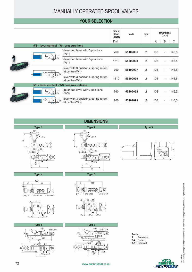
72 www.asconumatics.eu
DIMENSIONSType 1 Type 2 Type 3
A
51,5 33
27,5
==
32 ==
45 ==
62B
9,5
7 13
21
32°= =
Ø18
2 x Ø5,3
3
2
A
51 3222
27,5
==
32 ==
45 ==
72B
C
20,5
7 5 3
= =
4 2
32°= =
Ø18
2 x Ø5,3
5 31
14 2
A
BC
123
45
G 1/4"
Type 4 Type 5
378
88133
457
45=
=27
,5=
=
3 Ø G1/4Ø16 x 15019
123
3 12
21,527,5
36 228
100145
457
45 ==
27,5
==
5 Ø G1/4Ø16 x 15019
15 4 2 3
45 3
21
20,520,526,5
= =
Type 6 Type 7
Ports1 : Pressure2-4 : Outlet3-5 : Exhaust
45 ==
27,5
==
12
188
3
123
3 Ø G1/4
3
1
2
9,5
== =
= ==73 57 37
77
4713 128
2
72 11
45 ==
27,5
==
5 Ø G1/4
15 4 2 3
20022==4
5 3
2
1
20,520,5
== =
= ==73 57 37
87
4713 140
4
2
72 11
flow at 6 bar
(ANR)code type dimensions
(mm)
l/min A B C5/3 - lever control - W1 pressure held
24
35
1
detended lever with 3 positions (W1) 760 55102096 2 108 - 146,5
detended lever with 3 positions (W1) 1610 55200038 2 108 - 146,5
24
35
1
lever with 3 positions, spring return at centre (W1) 760 55102097 2 108 - 146,5
lever with 3 positions, spring return at centre (W1) 1610 55200039 2 108 - 146,5
5/3 - lever control - W3 pressure release24
35
1detended lever with 3 positions (W3) 760 55102098 2 108 - 146,5
24
35
1lever with 3 positions, spring return at centre (W3) 760 55102099 2 108 - 146,5
MANUALLY OPERATED SPOOL VALVESYOUR SELECTION
2013
/R01
Ava
ilabi
lity,
des
ign
and
spec
ifica
tions
are
sub
ject
to c
hang
e w
ithou
t not
ice.
All
right
s re
serv
ed.
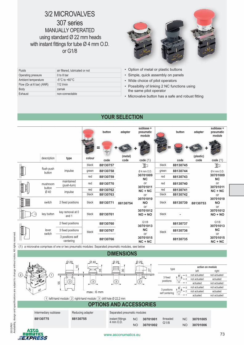
73www.asconumatics.eu
3/2 MICROVALVES 307 series
MANUALLY OPERATED using standard Ø 22 mm heads
with instant fittings for tube Ø 4 mm O.D.or G1/8
Fluids air filtered, lubricated or notOperating pressure 0 to 8 barAmbient temperature -5°C to +60°CFlow (Qv at 6 bar) (ANR) 112 l/min Body zamakExhaust non-connectable
button adaptersubbase +pneumatic
modulebutton adapter
subbase +pneumatic
module
description type colour (metal) (plastic)code code code (1) code code code (1)
flush push button impulse
black 88130757
88130754
*Ø 4 mm O.D.30701009
NCor
30701011NC + NC
or30701010
NOor
30701012NO + NO
G1/830701013
NCor
30701015NC + NC
black 88130745
88130753
*Ø 4 mm O.D.30701009
NCor
30701011NC + NC
or30701010
NOor
30701012NO + NO
G1/830701013
NCor
30701015NC + NC
green 88130758 green 88130744red 88130759 red 88130743
mushroom buttonØ 40
maintained(push-turn) red 88130770 red 88130740
impulsered 88130762 red 88130741
black 88130763 black 88130742
switch 2 fixed positions black 88130771 black 88130739
key button key removal at 0 and 1 black 88130761 black -
lever switch
2 fixed positions
black
88130760
black
88130737
3 fixed positions 88130767 88130736
3 positions self centering 88130766 88130735
(1) a microvalve comprises of one or two pneumatic modules: Separated pneumatic modules, see below
DIMENSIONS
4030
12
Ø 29 Ø 29
10
Ø 40 Ø 29
55
33 30 27
24
333 3
1 left-hand module 2 right-hand module 3 drill hole Ø 22,2 mm
• Option of metal or plastic buttons• Simple, quick assembly on panels• Wide choice of pilot operators• Possibility of linking 2 NC functions using
the same pilot operator• Microvalve button has a safe and robust fitting
+ +=
type action on moduleleft right
3 fixed positions
1
1 20 0
2
not actuated not actuatednot actuated actuated
actuated not actuated
3 positions self centering
1
1 20 0
2
not actuated not actuatednot actuated actuated
actuated not actuated
+ +=
YOUR SELECTION
OPTIONS AND ACCESSORIESIntermediary subbase Reducing adapter Separated pneumatic modules
88130775 88130755 instant fittings 4 mm O.D.
NC 30701001 threadedG1/8
NC 30701005
NO 30701002 NO 30701006
max.: 6 mm
2013
/R01
Ava
ilabi
lity,
des
ign
and
spec
ifica
tions
are
sub
ject
to c
hang
e w
ithou
t not
ice.
All
right
s re
serv
ed.
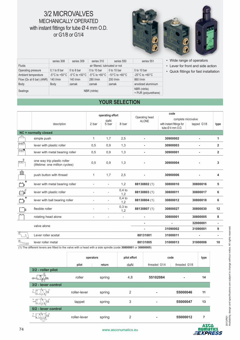
74 www.asconumatics.eu
3/2 MICROVALVESMECHANICALLY OPERATED
with instant fittings for tube Ø 4 mm O.D.or G1/8 or G1/4
series 308 series 309 series 310 series 550 series 551Fluids air filtered, lubricated or notOperating pressure 0,1 to 8 bar 0 to 8 bar 0 to 10 bar 0 to 10 bar 0 to 10 barAmbient temperature -5°C to +50°C -5°C to +50°C -5°C to +60°C -10°C to +60°C -25°C to +60°CFlow (Qv at 6 bar) (ANR) 140 l/min 140 l/min 280 l/min 200 l/min 860 l/minBody Body zamak zamak zamak anodized aluminium
Sealings NBR (nitrile) NBR (nitrile) + PUR (polyurethane)
operating effort codeOperating head
ALONE complete microvalvedaNdescription 2 bar 5 bar 8 bar with instant fittings for
tube Ø 4 mm O.D.tapped G1/8 type
NC = normally closed
simple push 1 1,7 2,5 - 30900002 - 1
lever with plastic roller 0,5 0,9 1,3 - 30900003 - 2
lever with metal bearing roller 0,5 0,9 1,3 - 30900001 - 2
one way trip plastic roller(lifetime: one million cycles) 0,5 0,9 1,3 - 30900004 - 3
push button with thread 1 1,7 2,5 - 30900006 - 4
lever with metal bearing roller - - 1,2 88130802 (1) 30800010 30800016 5
lever with plastic roller - - 0,4 to 1,2 88130803 (1) 30800011 30800017 6
lever with ball bearing roller - - 0,4 to 1,2 88130804 (1) 30800012 30800018 6
flexible roller - - 0,3 to 1,2 88130807 (1) 30800027 30800030 12
rotating head alone - - - - 30800001 30800005 8
valve alone- - 32000001 -
- 31090002 31090001 9
Lever roller acetal 88131001 31000011 - -
lever roller metal 88131005 31000013 31000006 10(1) The different levers are fitted to the valve with a head with a side spindle (code 30800001 or 30800005)
• Wide range of operators• Lever for front and side action• Quick fittings for fast installation
YOUR SELECTION
operators pilot effort code type
pilot return daN threaded G1/4 threaded G1/83/2 - roller pilot
2
3 1
roller spring 4,8 55102084 - 14
3/2 - lever control12
2
1 3
10
roller-lever spring 2 - 55000046 11
122
1 3
10
tappet spring 3 - 55000047 13
5/2 - lever control14
2
5
124
31
roller-lever spring 2 - 55000012 7
2013
/R01
Ava
ilabi
lity,
des
ign
and
spec
ifica
tions
are
sub
ject
to c
hang
e w
ithou
t not
ice.
All
right
s re
serv
ed.
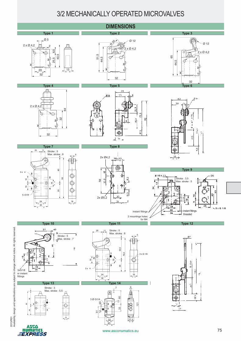
75www.asconumatics.eu
16
16
24
32==
==
==
3
1
16
2
3 x 4
76,5
50,5
26
==
25 11
5
3 x G 1/8
DIMENSIONSType 1 Type 2 Type 3
Ø 5
2 x Ø 4,2 2
25,5
6,5
40,5
32
20= =
13= =
2
13
2 x Ø 4,2
32
2
13
32
64
2 x Ø 4,2
Ø 12
32
2
13
44,5
R 20
51,5
2 x Ø 4,2
Ø 12
32
2
13
44,5
65
Ø 5
2 x Ø 4,2 2
25,5
6,5
40,5
32
20= =
13= =
2
13
2 x Ø 4,2
32
2
13
32
64
2 x Ø 4,2
Ø 12
32
2
13
44,5
R 20
51,5
2 x Ø 4,2
Ø 12
32
2
13
44,5
65
Type 4 Type 5 Type 6
Ø 5
2 x Ø 4,2 2
25,5
6,5
40,5
32
20= =
13= =
2
13
2 x Ø 4,2
32
2
13
32
64
2 x Ø 4,2
Ø 12
32
2
13
44,5
R 20
51,5
2 x Ø 4,2
Ø 12
32
2
13
44,5
65
Type 7 Type 8
93
6033
25 11
5
1624
32==
==
==
1
5
2
4
5 x G1/8
3 x 4
16=
=
1616
3
Type 10 Type 11 Type 12
Type 13 Type 14
26
64
3
1
2
16==
38
1233
1
45= =
27,5
6
= =32
= =
2
129,5
60
121
51
33
3 Ø G1/41
7
Ø 5
2 x Ø 4,2 2
25,5
6,5
40,5
32
20= =
13= =
2
13
2 x Ø 4,2
32
2
13
32
64
2 x Ø 4,2
Ø 12
32
2
13
44,5
R 20
51,5
2 x Ø 4,2
Ø 12
32
2
13
44,5
65Type 9
2x Ø4,2
2x Ø5,2
Ø6
xinstant fittings.threaded
2 mountings holes for M4
instant fittings
Stroke : 3,5Max. stroke : 5
Stroke : 5Max. stroke : 7
3xG1/8 or instant fittings
Stroke : 3Max. stroke : 5,5
Stroke : 5Max. stroke : 8
Stroke : 5Max. stroke : 8
2013
/R01
Ava
ilabi
lity,
des
ign
and
spec
ifica
tions
are
sub
ject
to c
hang
e w
ithou
t not
ice.
All
right
s re
serv
ed.
3/2 MECHANICALLY OPERATED MICROVALVES

76 www.asconumatics.eu
MINI SPOOL VALVES 3/2-5/2
550 seriesMANUALLY OPERATED
G1/8
Fluids air filtered, lubricated or notOperating pressure 0 to 10 barAmbient temperature -10°C to +60°CFlow (Qv at 6 bar) (ANR) 200 l/min Body anodized light alloy
• 3/2 spool valves can be used as a 3/2 NC or 3/2 NO, by connecting ports as indicated below
• Possible mounting panel (percing diameter 16,5)
operators code
control return return type 5/2 type
push button spring12 2
1 3
10
55000040 1
14 2
5
124
31
55000009 3
button push-pull12 2
1 3
55000039 1
2
5
4
31
14
55000010 3
lever - lever detended12 2
1 3
55000043 2
2
5
4
31
14
55000011 4
YOUR SELECTION
DIMENSIONSType 1 Type 3 Type 4
16
16
24
32==
==
==
3
1 3 x G1/8
16
2
3 x 4
26
51,5
92,5
41
1 16
Min
. : 3
Max
. : 7
27
21
Type 2
51,5
98,5
1 16
18
3
1
2
47
90
Min
. : 3
Max
. : 7
16==
1624
32==
==
==
1
5
3
2
4
16
33
3 x 4
5 x G1/8
1616
17
41
1
27
21
108
67
16
Min
. : 3
Max
. : 7
16
16==
1
5
3
2
4
67
114
1 16
18
47
90
Min
. : 3
Max
. : 7
5/2 Ports1 : Pressure2-4 : Outlet3-5 : Exhaust
3/2 NC Ports1 : Pressure2 : Outlet3 : Exhaust
3/2 NO Ports1 : Exhaust2 : Outlet3 : Pressure
2013
/R01
Ava
ilabi
lity,
des
ign
and
spec
ifica
tions
are
sub
ject
to c
hang
e w
ithou
t not
ice.
All
right
s re
serv
ed.
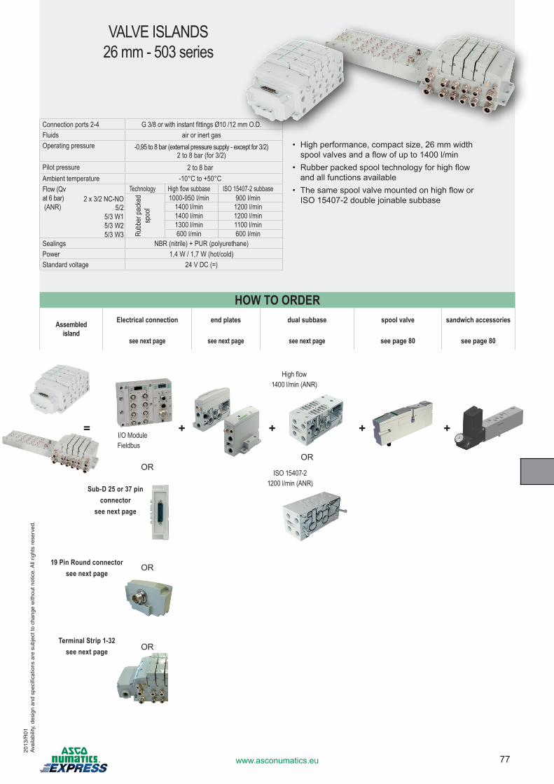
77www.asconumatics.eu
VALVE ISLANDS 26 mm - 503 series
Connection ports 2-4 G 3/8 or with instant fittings Ø10 /12 mm O.D.Fluids air or inert gasOperating pressure -0,95 to 8 bar (external pressure supply - except for 3/2)
2 to 8 bar (for 3/2)Pilot pressure 2 to 8 barAmbient temperature -10°C to +50°CFlow (Qv at 6 bar) (ANR)
Technology High flow subbase ISO 15407-2 subbase2 x 3/2 NC-NO
Rubb
er pa
cked
sp
ool
1000-950 l/min 900 l/min5/2 1400 l/min 1200 l/min
5/3 W1 1400 l/min 1200 l/min5/3 W2 1300 l/min 1100 l/min5/3 W3 600 l/min 600 l/min
Sealings NBR (nitrile) + PUR (polyurethane)Power 1,4 W / 1,7 W (hot/cold)Standard voltage 24 V DC (=)
Assembled island
Electrical connection end plates dual subbase spool valve sandwich accessories
see next page see next page see next page see page 80 see page 80
OROR
OR
OR
• High performance, compact size, 26 mm width spool valves and a flow of up to 1400 l/min
• Rubber packed spool technology for high flow and all functions available
• The same spool valve mounted on high flow or ISO 15407-2 double joinable subbase
HOW TO ORDER
= + + + +
High flow 1400 l/min (ANR)
ISO 15407-2 1200 l/min (ANR)
Sub-D 25 or 37 pin connector
see next page
I/O ModuleFieldbus
19 Pin Round connector see next page
Terminal Strip 1-32 see next page
2013
/R01
Ava
ilabi
lity,
des
ign
and
spec
ifica
tions
are
sub
ject
to c
hang
e w
ithou
t not
ice.
All
right
s re
serv
ed.
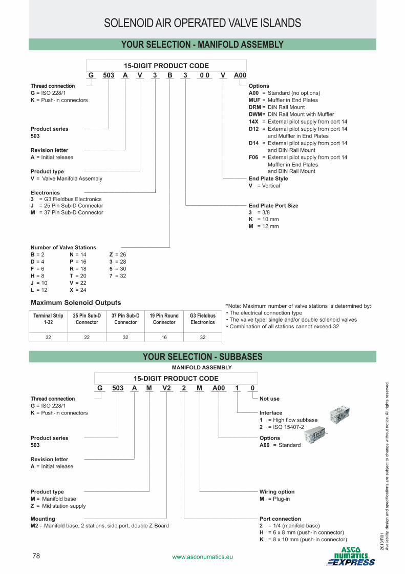
78 www.asconumatics.eu
* Note: Maximum number of valve stations is determined by:• The electrical connection type• The valve type: single and/or double solenoid valves• Combination of all stations cannot exceed 32
Maximum Solenoid Outputs
15-DIGIT PRODUCT CODEG 503 A V 3 B 3 0 0 V A00
Thread connection OptionsG = ISO 228/1 A00 = Standard (no options)K = Push-in connectors MUF = Muffler in End Plates
DRM = DIN Rail MountDWM = DIN Rail Mount with Muffler14X = External pilot supply from port 14
Product series D12 = External pilot supply from port 14503 and Muffler in End Plates
D14 = External pilot supply from port 14Revision letter and DIN Rail MountA = Initial release F06 = External pilot supply from port 14
Muffler in End Plates and DIN Rail MountProduct type
V = Valve Manifold Assembly End Plate StyleV = Vertical
Electronics3 = G3 Fieldbus Electronics J = 25 Pin Sub-D Connector End Plate Port SizeM = 37 Pin Sub-D Connector 3 = 3/8
K = 10 mmM = 12 mm
Number of Valve StationsB = 2 N = 14 Z = 26D = 4 P = 16 3 = 28F = 6 R = 18 5 = 30H = 8 T = 20 7 = 32J = 10 V = 22L = 12 X = 24
Terminal Strip 1-32
25 Pin Sub-D Connector
37 Pin Sub-D Connector
19 Pin Round Connector
G3 Fieldbus Electronics
32 22 32 16 32
15-DIGIT PRODUCT CODEG 503 A M V2 2 M A00 1 0
Thread connection Not useG = ISO 228/1K = Push-in connectors Interface
1 = High flow subbase2 = ISO 15407-2
Product series Options503 A00 = Standard
Revision letterA = Initial release
Product type Wiring optionM = Manifold base M = Plug-inZ = Mid station supply
Mounting Port connectionM2 = Manifold base, 2 stations, side port, double Z-Board 2 = 1/4 (manifold base)
H = 6 x 8 mm (push-in connector)K = 8 x 10 mm (push-in connector)
YOUR SELECTION - MANIFOLD ASSEMBLY
SOLENOID AIR OPERATED VALVE ISLANDS
YOUR SELECTION - SUBBASESMANIFOLD ASSEMBLY
2013
/R01
Ava
ilabi
lity,
des
ign
and
spec
ifica
tions
are
sub
ject
to c
hang
e w
ithou
t not
ice.
All
right
s re
serv
ed.
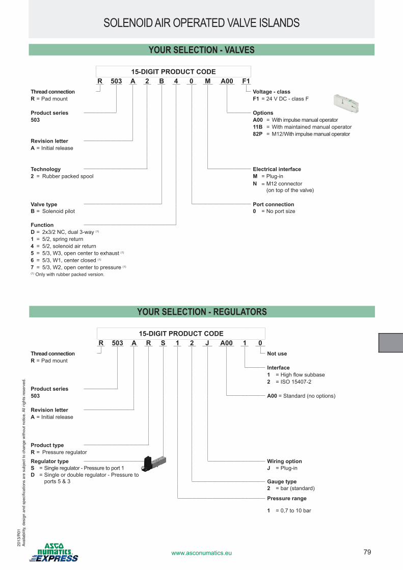
79www.asconumatics.eu
SOLENOID AIR OPERATED VALVE ISLANDS
YOUR SELECTION - VALVES
15-DIGIT PRODUCT CODER 503 A 2 B 4 0 M A00 F1
Thread connection Voltage - classR = Pad mount F1 = 24 V DC - class F
Product series Options503 A00 = With impulse manual operator
11B = With maintained manual operator82P = M12/With impulse manual operator
Revision letterA = Initial release
Technology Electrical interface2 = Rubber packed spool M = Plug-in
N = M12 connector (on top of the valve)
Valve type Port connectionB = Solenoid pilot 0 = No port size
FunctionD = 2x3/2 NC, dual 3-way (1)
1 = 5/2, spring return4 = 5/2, solenoid air return5 = 5/3, W3, open center to exhaust (1)
6 = 5/3, W1, center closed (1)
7 = 5/3, W2, open center to pressure (1)
(1) Only with rubber packed version.
15-DIGIT PRODUCT CODER 503 A R S 1 2 J A00 1 0
Thread connection Not useR = Pad mount
Interface1 = High flow subbase2 = ISO 15407-2
Product series503 A00 = Standard (no options)
Revision letterA = Initial release
Product typeR = Pressure regulator
Regulator type Wiring optionS = Single regulator - Pressure to port 1 J = Plug-inD = Single or double regulator - Pressure to
ports 5 & 3 Gauge type2 = bar (standard)
Pressure range
1 = 0,7 to 10 bar
YOUR SELECTION - REGULATORS
2013
/R01
Ava
ilabi
lity,
des
ign
and
spec
ifica
tions
are
sub
ject
to c
hang
e w
ithou
t not
ice.
All
right
s re
serv
ed.
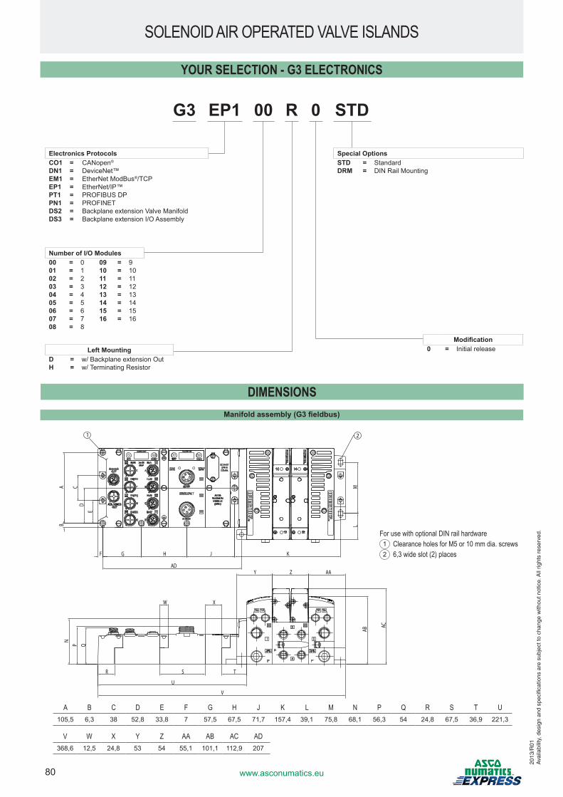
80 www.asconumatics.eu
Modification0 = Initial release
G3 EP1 00 R 0 STD
Number of I/O Modules00 = 0 09 = 901 = 1 10 = 1002 = 2 11 = 1103 = 3 12 = 1204 = 4 13 = 1305 = 5 14 = 1406 = 6 15 = 1507 = 7 16 = 1608 = 8
Electronics ProtocolsCO1 = CANopen®
DN1 = DeviceNet™EM1 = EtherNet ModBus®/TCPEP1 = EtherNet/IP™PT1 = PROFIBUS DPPN1 = PROFINETDS2 = Backplane extension Valve ManifoldDS3 = Backplane extension I/O Assembly
Left MountingD = w/ Backplane extension OutH = w/ Terminating Resistor
Special OptionsSTD = StandardDRM = DIN Rail Mounting
YOUR SELECTION - G3 ELECTRONICS
Manifold assembly (G3 fieldbus)
A
DC
E
B
F G H J K
ML
AC
AB
NP Q
R
U
TS
W X
Y Z AA
V
AD
21
V W X Y Z AA AB AC AD368,6 12,5 24,8 53 54 55,1 101,1 112,9 207
DIMENSIONS
A B C D E F G H J K L M N P Q R S T U105,5 6,3 38 52,8 33,8 7 57,5 67,5 71,7 157,4 39,1 75,8 68,1 56,3 54 24,8 67,5 36,9 221,3
For use with optional DIN rail hardware1 Clearance holes for M5 or 10 mm dia. screws2 6,3 wide slot (2) places
SOLENOID AIR OPERATED VALVE ISLANDS
2013
/R01
Ava
ilabi
lity,
des
ign
and
spec
ifica
tions
are
sub
ject
to c
hang
e w
ithou
t not
ice.
All
right
s re
serv
ed.
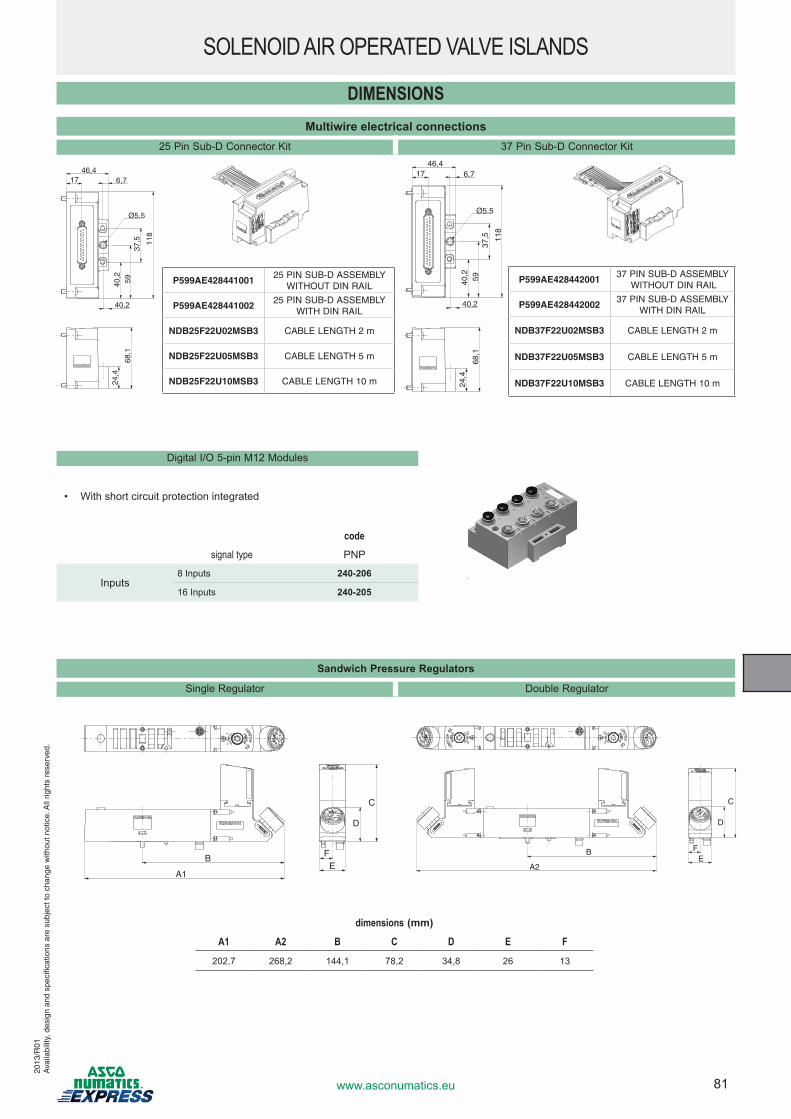
81www.asconumatics.eu
SOLENOID AIR OPERATED VALVE ISLANDS
DIMENSIONS
46,417 6,7
Ø5.5
40,2
40,2
68,1
24,4
5937
,5 118
46,417 6,7
Ø5.5
40,2
40,2
68,1
24,4
5937
,5 118
Multiwire electrical connections25 Pin Sub-D Connector Kit 37 Pin Sub-D Connector Kit
Digital I/O 5-pin M12 Modules
A1
B
C
D
FE A2
B
C
D
FE
dimensions (mm)
A1 A2 B C D E F
202,7 268,2 144,1 78,2 34,8 26 13
Sandwich Pressure Regulators
Single Regulator Double Regulator
2013
/R01
Ava
ilabi
lity,
des
ign
and
spec
ifica
tions
are
sub
ject
to c
hang
e w
ithou
t not
ice.
All
right
s re
serv
ed.
P599AE42844200137 PIN SUB-D ASSEMBLY
WITHOUT DIN RAIL
P599AE42844200237 PIN SUB-D ASSEMBLY
WITH DIN RAIL
NDB37F22U02MSB3 CABLE LENGTH 2 m
NDB37F22U05MSB3 CABLE LENGTH 5 m
NDB37F22U10MSB3 CABLE LENGTH 10 m
P599AE42844100125 PIN SUB-D ASSEMBLY
WITHOUT DIN RAIL
P599AE42844100225 PIN SUB-D ASSEMBLY
WITH DIN RAIL
NDB25F22U02MSB3 CABLE LENGTH 2 m
NDB25F22U05MSB3 CABLE LENGTH 5 m
NDB25F22U10MSB3 CABLE LENGTH 10 m
codesignal type PNP
Inputs8 Inputs 240-206
16 Inputs 240-205
• With short circuit protection integrated
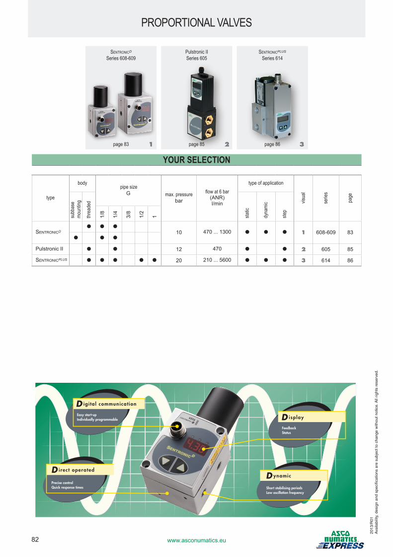
82 www.asconumatics.eu
SentronicD
Series 608-609Pulstronic IISeries 605
SentronicPLUS
Series 614
page 83 page 85 page 86
YOUR SELECTION
type
body pipe size
G max. pressurebar
flow at 6 bar(ANR) l/min
type of application
visua
l
serie
s
page
subb
ase
moun
ting
threa
ded
static
dyna
mic
step
1/8
1/4
3/8
1/2
1
SentronicD● ● ●
10 470 ... 1300 ● ● ● 1 608-609 83● ● ●
Pulstronic II ● ● 12 470 ● ● 2 605 85
SentronicPLUS ● ● ● ● ● 20 210 ... 5600 ● ● ● 3 614 86
PROPORTIONAL VALVES
1 2 3
2013
/R01
Ava
ilabi
lity,
des
ign
and
spec
ifica
tions
are
sub
ject
to c
hang
e w
ithou
t not
ice.
All
right
s re
serv
ed.
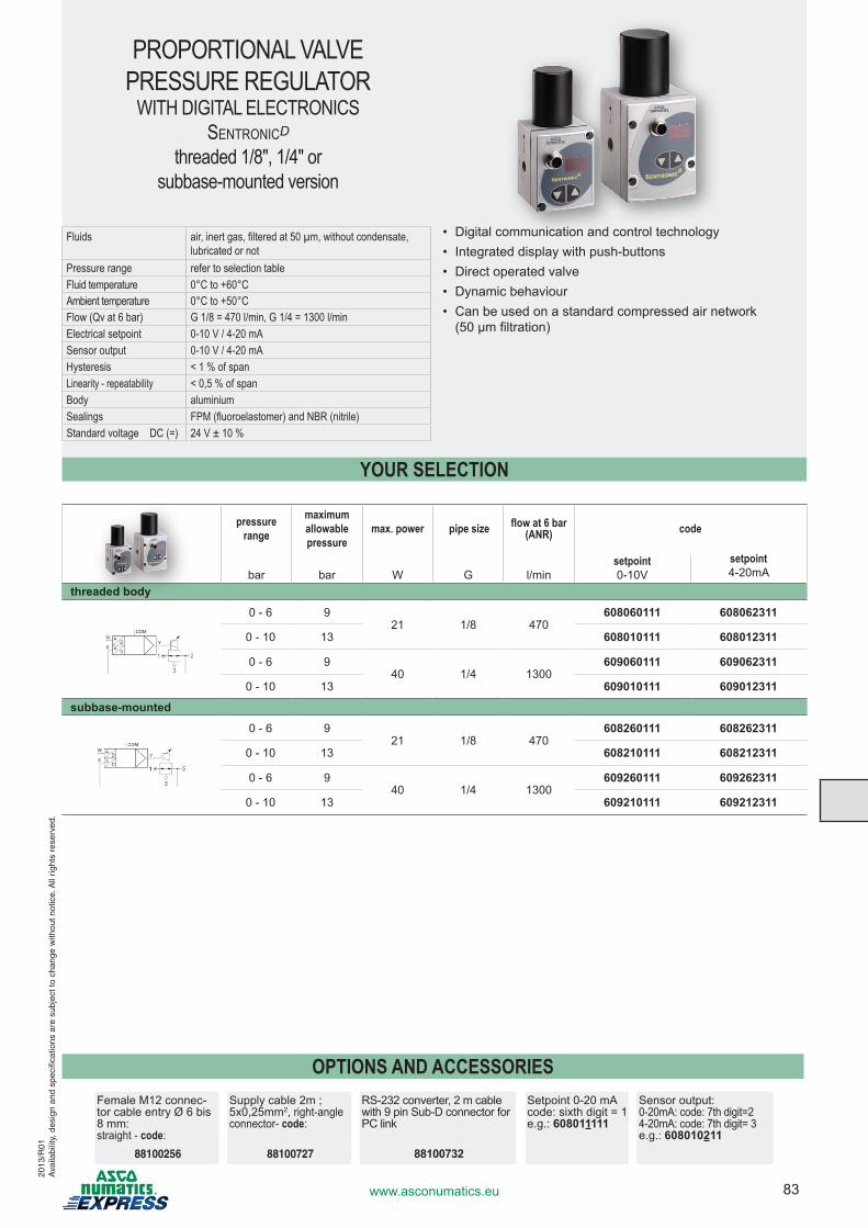
83www.asconumatics.eu
OPTIONS AND ACCESSORIESFemale M12 connec-tor cable entry Ø 6 bis 8 mm:straight - code:
Supply cable 2m ; 5x0,25mm2, right-angle connector- code:
RS-232 converter, 2 m cable with 9 pin Sub-D connector for PC link
Setpoint 0-20 mAcode: sixth digit = 1e.g.: 608011111
Sensor output: 0-20mA: code: 7th digit=24-20mA: code: 7th digit= 3e.g.: 608010211
88100256 88100727 88100732
PROPORTIONAL VALVE PRESSURE REGULATOR
WITH DIGITAL ELECTRONICSSentronicD
threaded 1/8", 1/4" orsubbase-mounted version
Fluids air, inert gas, filtered at 50 µm, without condensate,lubricated or not
Pressure range refer to selection tableFluid temperature 0°C to +60°CAmbient temperature 0°C to +50°CFlow (Qv at 6 bar) G 1/8 = 470 l/min, G 1/4 = 1300 l/minElectrical setpoint 0-10 V / 4-20 mASensor output 0-10 V / 4-20 mAHysteresis < 1 % of spanLinearity - repeatability < 0,5 % of spanBody aluminiumSealings FPM (fluoroelastomer) and NBR (nitrile)Standard voltage DC (=) 24 V ± 10 %
• Digital communication and control technology• Integrated display with push-buttons• Direct operated valve• Dynamic behaviour• Can be used on a standard compressed air network
(50 µm filtration)
pressure range
maximumallowablepressure
max. power pipe size flow at 6 bar (ANR) code
bar bar W G l/minsetpoint 0-10V
setpoint 4-20mA
threaded body
0 - 6 921 1/8 470
608060111 608062311
0 - 10 13 608010111 608012311
0 - 6 940 1/4 1300
609060111 609062311
0 - 10 13 609010111 609012311
subbase-mounted
0 - 6 921 1/8 470
608260111 608262311
0 - 10 13 608210111 608212311
0 - 6 940 1/4 1300
609260111 609262311
0 - 10 13 609210111 609212311
YOUR SELECTION
2013
/R01
Ava
ilabi
lity,
des
ign
and
spec
ifica
tions
are
sub
ject
to c
hang
e w
ithou
t not
ice.
All
right
s re
serv
ed.
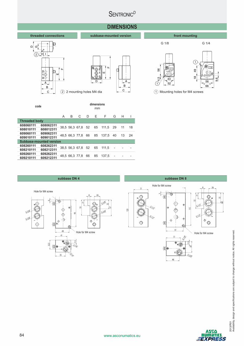
84 www.asconumatics.eu
SentronicD
1 Mounting holes for M4 screws2 2 mounting holes M4 dia
DIMENSIONSthreaded connections subbase-mounted version front mounting
B
A
C
H I
F
E
G
12
3
D
2
12
3
B
AD
C
F
E
G 1/8 G 1/4
52
43= =4,
556
166
56= =
1849
1
9,6
code dimensionsmm
A B C D E F G H IThreaded body608060111 608062311 38,5 56,3 67,8 52 65 111,5 29 11 18608010111 608012311609060111 609062311 48,5 66,3 77,8 66 85 137,5 40 13 24609010111 609012311Subbase-mounted version608260111 608262311 38,5 56,3 67,8 52 65 111,5 - - -608210111 608212311609260111 609262311 48,5 66,3 77,8 66 85 137,5 - - -609210111 609212311
subbase DN 4 subbase DN 8
Hole for M4 screw
Hole for M4 screw
Hole for M4 screw
Hole for M4 screw
2013
/R01
Ava
ilabi
lity,
des
ign
and
spec
ifica
tions
are
sub
ject
to c
hang
e w
ithou
t not
ice.
All
right
s re
serv
ed.
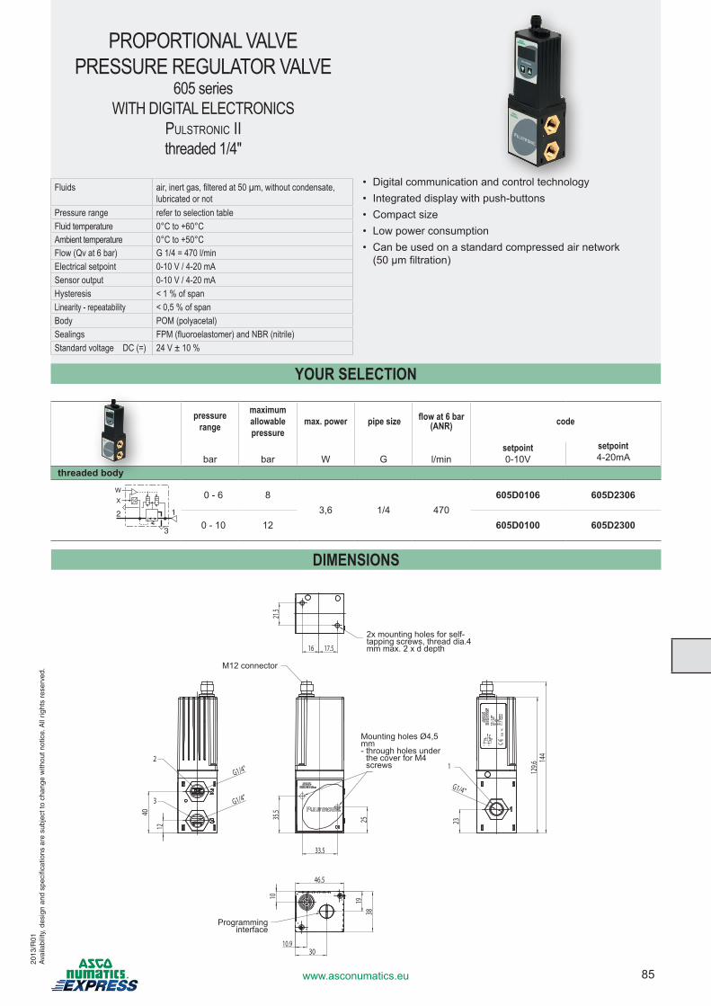
85www.asconumatics.eu
DIMENSIONS
2x mounting holes for self-tapping screws, thread dia.4 mm max. 2 x d depth
Mounting holes Ø4,5 mm - through holes under
the cover for M4 screws
M12 connector
Programming interface
PROPORTIONAL VALVE PRESSURE REGULATOR VALVE
605 seriesWITH DIGITAL ELECTRONICS
PulStronic ii threaded 1/4"
Fluids air, inert gas, filtered at 50 µm, without condensate,lubricated or not
Pressure range refer to selection tableFluid temperature 0°C to +60°CAmbient temperature 0°C to +50°CFlow (Qv at 6 bar) G 1/4 = 470 l/minElectrical setpoint 0-10 V / 4-20 mASensor output 0-10 V / 4-20 mAHysteresis < 1 % of spanLinearity - repeatability < 0,5 % of spanBody POM (polyacetal)Sealings FPM (fluoroelastomer) and NBR (nitrile)Standard voltage DC (=) 24 V ± 10 %
• Digital communication and control technology• Integrated display with push-buttons• Compact size• Low power consumption• Can be used on a standard compressed air network
(50 µm filtration)
pressure range
maximumallowablepressure
max. power pipe size flow at 6 bar (ANR) code
bar bar W G l/minsetpoint 0-10V
setpoint 4-20mA
threaded body
1
3
2
X
W 0 - 6 83,6 1/4 470
605D0106 605D2306
0 - 10 12 605D0100 605D2300
YOUR SELECTION
2013
/R01
Ava
ilabi
lity,
des
ign
and
spec
ifica
tions
are
sub
ject
to c
hang
e w
ithou
t not
ice.
All
right
s re
serv
ed.
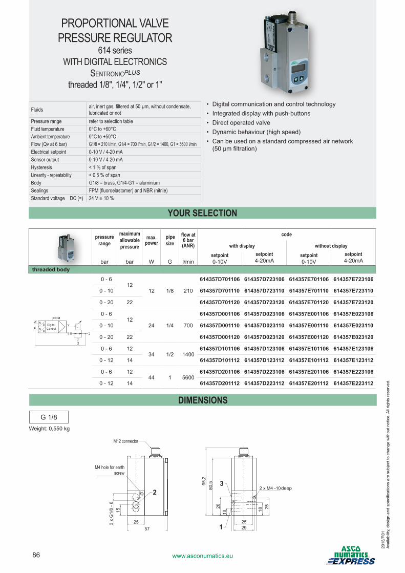
86 www.asconumatics.eu
PROPORTIONAL VALVE PRESSURE REGULATOR
614 seriesWITH DIGITAL ELECTRONICS
SentronicPLUS threaded 1/8", 1/4", 1/2" or 1"
Fluids air, inert gas, filtered at 50 µm, without condensate,lubricated or not
Pressure range refer to selection tableFluid temperature 0°C to +60°CAmbient temperature 0°C to +50°CFlow (Qv at 6 bar) G1/8 = 210 l/min, G1/4 = 700 l/min, G1/2 = 1400, G1 = 5600 l/minElectrical setpoint 0-10 V / 4-20 mASensor output 0-10 V / 4-20 mAHysteresis < 1 % of spanLinearity - repeatability < 0,5 % of spanBody G1/8 = brass, G1/4-G1 = aluminiumSealings FPM (fluoroelastomer) and NBR (nitrile)Standard voltage DC (=) 24 V ± 10 %
• Digital communication and control technology• Integrated display with push-buttons• Direct operated valve• Dynamic behaviour (high speed)• Can be used on a standard compressed air network
(50 µm filtration)
pressure range
maximumallowablepressure
max. power
pipe size
flow at 6 bar (ANR)
code
with display without display
bar bar W G l/minsetpoint 0-10V
setpoint 4-20mA
setpoint 0-10V
setpoint 4-20mA
threaded body
0 - 612
12 1/8 210
614357D701106 614357D723106 614357E701106 614357E723106
0 - 10 614357D701110 614357D723110 614357E701110 614357E723110
0 - 20 22 614357D701120 614357D723120 614357E701120 614357E723120
0 - 612
24 1/4 700
614357D001106 614357D023106 614357E001106 614357E023106
0 - 10 614357D001110 614357D023110 614357E001110 614357E023110
0 - 20 22 614357D001120 614357D023120 614357E001120 614357E023120
0 - 6 1234 1/2 1400
614357D101106 614357D123106 614357E101106 614357E123106
0 - 12 14 614357D101112 614357D123112 614357E101112 614357E123112
0 - 6 1244 1 5600
614357D201106 614357D223106 614357E201106 614357E223106
0 - 12 14 614357D201112 614357D223112 614357E201112 614357E223112
YOUR SELECTION
DIMENSIONSG 1/8
Weight: 0,550 kg
2013
/R01
Ava
ilabi
lity,
des
ign
and
spec
ifica
tions
are
sub
ject
to c
hang
e w
ithou
t not
ice.
All
right
s re
serv
ed.
M12 connector
2557 29
25
35
15 18 25
1026
80,595
,2
2 x M4 -10
3 x
G1/
8 - 8
23
1
M4 hole for earth screw
deep
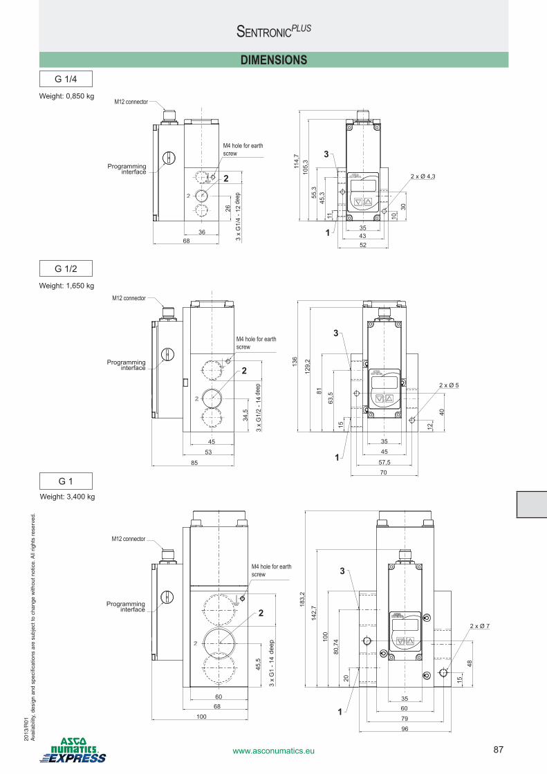
87www.asconumatics.eu
SentronicPLUS
Weight: 1,650 kg
Weight: 0,850 kg
DIMENSIONS
Weight: 3,400 kg
2013
/R01
Ava
ilabi
lity,
des
ign
and
spec
ifica
tions
are
sub
ject
to c
hang
e w
ithou
t not
ice.
All
right
s re
serv
ed.
Programming interface
M4 hole for earth screw
M12 connector
3668
4335
52
26
1030
1145
,355,3
105,
311
4,7
3 x
G1/
4 - 1
2
2
3
1
2 x Ø 4,3
M12 connector
Programming interface
M4 hole for earth screw
53
45
85
45
35
57,5
70
34,5
12
40
15
63,581
129,
2
136
3 x
G1/
2 - 1
4
2
3
1
2 x Ø 5
M4 hole for earth screw
Programming interface
6860
1006035
79
96
45,5
1548
2080
,7410
0
142,
7183,
2
3 x
G1
- 14
2
3
1
2 x Ø 7
M12 connector
deep
deep
deep
G 1
G 1/2
G 1/4
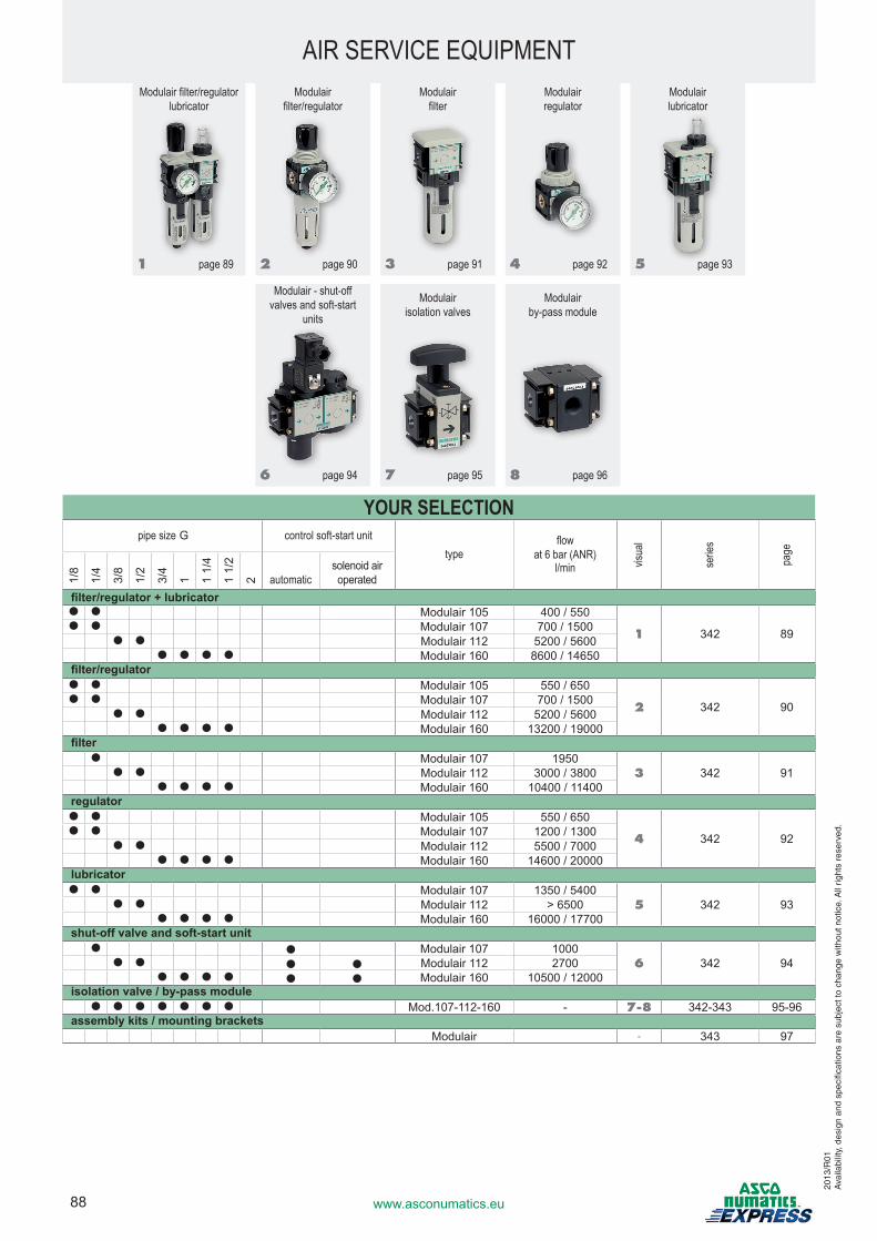
88 www.asconumatics.eu
Modulair filter/regulator lubricator
Modulair filter/regulator
Modulair filter
Modulair regulator
Modulair lubricator
1 page 89 2 page 90 3 page 91 4 page 92 5 page 93
Modulair - shut-off valves and soft-start
units
Modulair isolation valves
Modulair by-pass module
6 page 94 7 page 95 8 page 96
YOUR SELECTION pipe size G control soft-start unit
typeflow
at 6 bar (ANR)l/min vis
ual
serie
s
page
1/8
1/4
3/8
1/2
3/4
1 1 1/
4
1 1/
2
2 automaticsolenoid air operated
filter/regulator + lubricator● ● Modulair 105 400 / 550
1 342 89● ● Modulair 107 700 / 1500
● ● Modulair 112 5200 / 5600● ● ● ● Modulair 160 8600 / 14650
filter/regulator● ● Modulair 105 550 / 650
2 342 90● ● Modulair 107 700 / 1500
● ● Modulair 112 5200 / 5600● ● ● ● Modulair 160 13200 / 19000
filter● Modulair 107 1950
3 342 91● ● Modulair 112 3000 / 3800● ● ● ● Modulair 160 10400 / 11400
regulator● ● Modulair 105 550 / 650
4 342 92● ● Modulair 107 1200 / 1300
● ● Modulair 112 5500 / 7000● ● ● ● Modulair 160 14600 / 20000
lubricator● ● Modulair 107 1350 / 5400
5 342 93● ● Modulair 112 > 6500● ● ● ● Modulair 160 16000 / 17700
shut-off valve and soft-start unit● ● Modulair 107 1000
6 342 94● ● ● ● Modulair 112 2700● ● ● ● ● ● Modulair 160 10500 / 12000
isolation valve / by-pass module● ● ● ● ● ● ● Mod.107-112-160 - 7-8 342-343 95-96
assembly kits / mounting bracketsModulair - 343 97
AIR SERVICE EQUIPMENT
2013
/R01
Ava
ilabi
lity,
des
ign
and
spec
ifica
tions
are
sub
ject
to c
hang
e w
ithou
t not
ice.
All
right
s re
serv
ed.
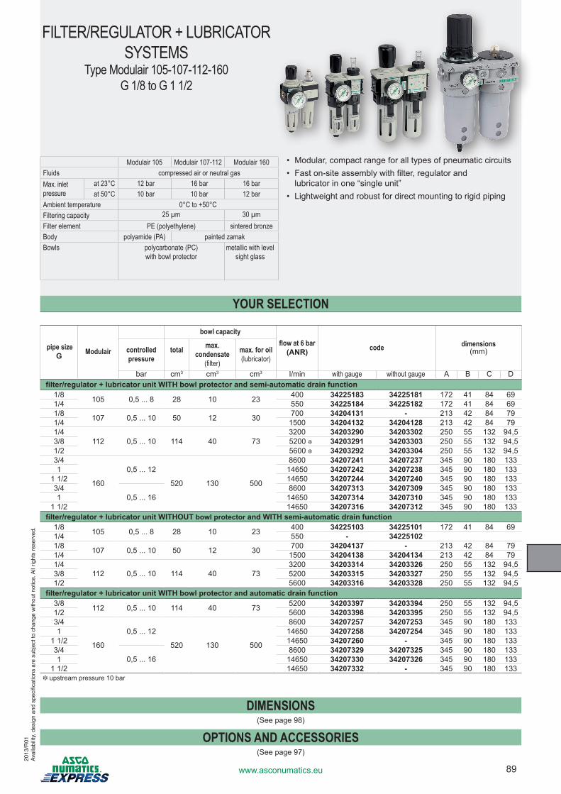
89www.asconumatics.eu
FILTER/REGULATOR + LUBRICATOR SYSTEMS
Type Modulair 105-107-112-160G 1/8 to G 1 1/2
Modulair 105 Modulair 107-112 Modulair 160Fluids compressed air or neutral gasMax. inlet pressure
at 23°C 12 bar 16 bar 16 barat 50°C 10 bar 10 bar 12 bar
Ambient temperature 0°C to +50°CFiltering capacity 25 µm 30 µmFilter element PE (polyethylene) sintered bronzeBody polyamide (PA) painted zamak Bowls
polycarbonate (PC) with bowl protector
metallic with level sight glass
• Modular, compact range for all types of pneumatic circuits• Fast on-site assembly with filter, regulator and
lubricator in one “single unit”• Lightweight and robust for direct mounting to rigid piping
YOUR SELECTION
pipe size G Modulair
bowl capacityflow at 6 bar
(ANR) code dimensions (mm)controlled
pressuretotal max.
condensate (filter)
max. for oil (lubricator)
bar cm3 cm3 cm3 l/min with gauge without gauge A B C Dfilter/regulator + lubricator unit WITH bowl protector and semi-automatic drain function
1/8 105 0,5 ... 8 28 10 23 400 34225183 34225181 172 41 84 691/4 550 34225184 34225182 172 41 84 691/8 107 0,5 ... 10 50 12 30 700 34204131 - 213 42 84 791/4 1500 34204132 34204128 213 42 84 791/4
112 0,5 ... 10 114 40 733200 34203290 34203302 250 55 132 94,5
3/8 5200 i 34203291 34203303 250 55 132 94,51/2 5600 i 34203292 34203304 250 55 132 94,53/4
160
0,5 ... 12
520 130 500
8600 34207241 34207237 345 90 180 1331 14650 34207242 34207238 345 90 180 133
1 1/2 14650 34207244 34207240 345 90 180 1333/4
0,5 ... 168600 34207313 34207309 345 90 180 133
1 14650 34207314 34207310 345 90 180 1331 1/2 14650 34207316 34207312 345 90 180 133
filter/regulator + lubricator unit WITHOUT bowl protector and WITH semi-automatic drain function1/8 105 0,5 ... 8 28 10 23 400 34225103 34225101 172 41 84 691/4 550 - 342251021/8 107 0,5 ... 10 50 12 30 700 34204137 - 213 42 84 791/4 1500 34204138 34204134 213 42 84 791/4
112 0,5 ... 10 114 40 733200 34203314 34203326 250 55 132 94,5
3/8 5200 34203315 34203327 250 55 132 94,51/2 5600 34203316 34203328 250 55 132 94,5
filter/regulator + lubricator unit WITH bowl protector and automatic drain function3/8 112 0,5 ... 10 114 40 73 5200 34203397 34203394 250 55 132 94,51/2 5600 34203398 34203395 250 55 132 94,53/4
160
0,5 ... 12
520 130 500
8600 34207257 34207253 345 90 180 1331 14650 34207258 34207254 345 90 180 133
1 1/2 14650 34207260 - 345 90 180 1333/4
0,5 ... 168600 34207329 34207325 345 90 180 133
1 14650 34207330 34207326 345 90 180 1331 1/2 14650 34207332 - 345 90 180 133
i upstream pressure 10 bar
DIMENSIONS(See page 98)
OPTIONS AND ACCESSORIES(See page 97)
2013
/R01
Ava
ilabi
lity,
des
ign
and
spec
ifica
tions
are
sub
ject
to c
hang
e w
ithou
t not
ice.
All
right
s re
serv
ed.
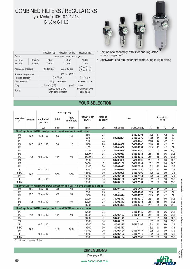
90 www.asconumatics.eu
COMBINED FILTERS / REGULATORSType Modulair 105-107-112-160
G 1/8 to G 1 1/2
Modulair 105 Modulair 107-112 Modulair 160Fluids compressed air or neutral gasMax. inlet pressure
at 23°C 12 bar 16 bar 16 barat 50°C 10 bar 10 bar 12 bar
Adjustable pressure 0,5 to 8 bar 0,5 to 10 bar 0,5 to 12 bar0,5 to 16 bar
Ambient temperature 0°C to +50°CFiltering capacity 5 or 25 µm 5 or 30 µmFilter element PE (polyethylene) sintered bronzeBody polyamide (PA) painted zamak
Bowls
polycarbonate (PC) with bowl protector
metallic with level sight glass
• Fast on-site assembly with filter and regulator in one “single unit”
• Lightweight and robust for direct mounting to rigid piping
YOUR SELECTION
pipe size G Modulair
bowl capacityflow at 6 bar
(ANR)filtering capacity code dimensions
(mm)controlled pressure
total max. condensate
bar cm3 cm3 l/min µm with gauge without gauge A B C Dfilter/regulator WITH bowl protector and semi-automatic drain
1/8 105 0,5 ... 8 28 10 550 25 - 34225201 172 41 42 691/4 650 25 34225204 34225202 172 41 42 691/8
107 0,5 ... 10 50 12700 25 - 34204045 213 42 42 79
1/4 1500 25 34204050 34204046 213 42 42 791/4 1100 5 34204056 34204052 213 42 42 791/4
112 0,5 ... 10 114 40
3200 25 34203086 34203080 251 55 66 94,53/8 5200 i 25 34203087 34203081 251 55 66 94,51/2 5600 i 25 34203088 34203082 251 55 66 94,51/4 3200 5 34203098 34203092 251 55 66 94,51/2 5600 5 34203100 34203094 251 55 66 94,53/4
160
0,5 ... 12
500 300
10100 30 34207093 34207089 182 90 90 1331 13500 30 34207094 34207090 182 90 90 133
1 1/2 13500 30 34207096 34207092 182 90 90 1333/4
0,5 ... 1610100 30 34207165 34207161 182 90 90 133
1 13500 30 34207166 34207162 182 90 90 1331 1/2 13500 30 34207168 34207164 182 90 90 133
filter/regulator WITHOUT bowl protector and WITH semi-automatic drain1/4 105 0,5 ... 8 28 10 650 25 34225124 34225122 172 41 42 691/8 107 0,5 ... 10 50 12 700 25 - 34204069 213 42 42 791/4 1500 25 34204074 34204070 213 42 42 791/4
112 0,5 ... 10 114 403200 25 34203372 34203340 251 55 66 94,5
3/8 5200 25 34203373 34203341 251 55 66 94,51/2 5600 25 34203374 34203342 251 55 66 94,5
filter/regulator WITH bowl protector and WITH automatic drain3/8
112 0,5 ... 10 114 405200 25 - 34203130 251 55 66 94,5
1/2 5600 25 34203137 34203131 251 55 66 94,51/2 5600 5 34203149 - 251 55 66 94,53/4
160
0,5 ... 12
160 300
10100 30 34207109 - 182 90 90 1331 13500 30 34207110 34207106 182 90 90 133
1 1/2 13500 30 34207112 - 182 90 90 1333/4
0,5 ... 1610100 30 34207181 34207177 182 90 90 133
1 13500 30 34207182 34207178 182 90 90 1331 1/2 13500 30 34207184 34207180 182 90 90 133
i upstream pressure 10 bar
DIMENSIONS(See page 98)
2013
/R01
Ava
ilabi
lity,
des
ign
and
spec
ifica
tions
are
sub
ject
to c
hang
e w
ithou
t not
ice.
All
right
s re
serv
ed.
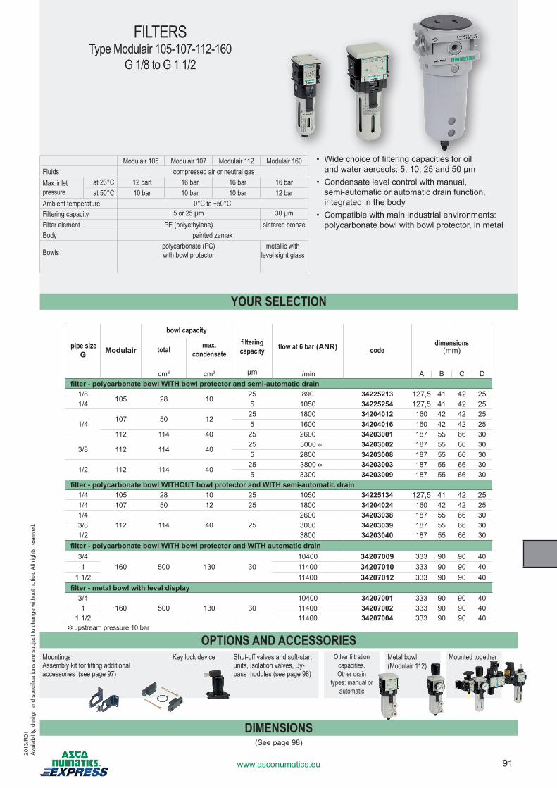
91www.asconumatics.eu
FILTERSType Modulair 105-107-112-160
G 1/8 to G 1 1/2
Modulair 105 Modulair 107 Modulair 112 Modulair 160Fluids compressed air or neutral gasMax. inlet pressure
at 23°C 12 bart 16 bar 16 bar 16 barat 50°C 10 bar 10 bar 10 bar 12 bar
Ambient temperature 0°C to +50°CFiltering capacity 5 or 25 µm 30 µmFilter element PE (polyethylene) sintered bronzeBody painted zamak
Bowls
polycarbonate (PC) with bowl protector
metallic with level sight glass
• Wide choice of filtering capacities for oil and water aerosols: 5, 10, 25 and 50 µm
• Condensate level control with manual, semi-automatic or automatic drain function, integrated in the body
• Compatible with main industrial environments: polycarbonate bowl with bowl protector, in metal
2013
/R01
Ava
ilabi
lity,
des
ign
and
spec
ifica
tions
are
sub
ject
to c
hang
e w
ithou
t not
ice.
All
right
s re
serv
ed.
YOUR SELECTION
pipe size G Modulair
bowl capacityfiltering capacity flow at 6 bar (ANR) code
dimensions (mm)total max.
condensate
cm3 cm3 µm l/min A B C Dfilter - polycarbonate bowl WITH bowl protector and semi-automatic drain
1/8105 28 10
25 890 34225213 127,5 41 42 251/4 5 1050 34225254 127,5 41 42 25
1/4107 50 12
25 1800 34204012 160 42 42 255 1600 34204016 160 42 42 25
112 114 40 25 2600 34203001 187 55 66 30
3/8 112 114 4025 3000 i 34203002 187 55 66 305 2800 34203008 187 55 66 30
1/2 112 114 4025 3800 i 34203003 187 55 66 305 3300 34203009 187 55 66 30
filter - polycarbonate bowl WITHOUT bowl protector and WITH semi-automatic drain1/4 105 28 10 25 1050 34225134 127,5 41 42 251/4 107 50 12 25 1800 34204024 160 42 42 251/4
112 114 40 252600 34203038 187 55 66 30
3/8 3000 34203039 187 55 66 301/2 3800 34203040 187 55 66 30
filter - polycarbonate bowl WITH bowl protector and WITH automatic drain3/4
160 500 130 3010400 34207009 333 90 90 40
1 11400 34207010 333 90 90 401 1/2 11400 34207012 333 90 90 40
filter - metal bowl with level display3/4
160 500 130 3010400 34207001 333 90 90 40
1 11400 34207002 333 90 90 401 1/2 11400 34207004 333 90 90 40
i upstream pressure 10 bar
DIMENSIONS(See page 98)
OPTIONS AND ACCESSORIESMountings Assembly kit for fitting additional accessories (see page 97)
Key lock device Shut-off valves and soft-start units, Isolation valves, By-pass modules (see page 98)
Other filtration capacities. Other drain
types: manual or automatic
Metal bowl(Modulair 112)
Mounted together
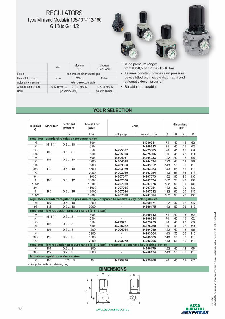
92 www.asconumatics.eu
REGULATORSType Mini and Modulair 105-107-112-160
G 1/8 to G 1 1/2
Mini Modulair105
Modulair 107-112-160
Fluids compressed air or neutral gasMax. inlet pressure 12 bar 12 bar 16 barAdjustable pressure refer to selection tableAmbient temperature -10°C to +60°C 0°C to +50°C -10°C to +60°CBody polyamide (PA) painted zamak
• Wide pressure range: from 0,2-0,5 bar to 3-8-10-16 bar
• Assures constant downstream pressure: device fitted with flexible diaphragm and automatic decompression
• Reliable and durable
YOUR SELECTION
pipe size G
Modulair controlled pressure
flow at 6 bar (ANR) code dimensions
(mm)
bar l/min with gauge without gauge A B C Dregulator - standard regulation pressure range
1/8 Mini (1) 0,5 ... 10 500 - 34200311 74 40 45 621/4 650 - 34200313 74 40 45 621/8 105 0,5 ... 8 550 34225007 34225005 90 41 42 691/4 650 34225008 34225006 90 41 42 691/8 107 0,5 ... 10 700 34504037 34204033 122 42 42 961/4 1200 34204038 34204034 122 42 42 961/4
112 0,5 ... 103900 34203058 34203052 143 55 66 113
3/8 5500 34203059 34203053 143 55 66 1131/2 7000 34203060 34203054 143 55 66 1133/4
160 0,5 ... 1211000 34207077 34207073 182 90 90 133
1 16000 34207078 34207074 182 90 90 1331 1/2 16000 34207080 34207076 182 90 90 1333/4
160 0,5 ... 1611000 34207085 34207081 182 90 90 133
1 16000 34207086 34207082 182 90 90 1331 1/2 16000 34207088 34207084 182 90 90 133
regulator - standard regulation pressure range - prepared to receive a key locking device1/4 107 0,5 ... 10 1300 - 34260171 122 42 42 963/8 112 0,5 ... 10 3000 - 34260175 143 55 66 113
regulator - low regulation pressure range (0,2 - 3 bar)1/8 Mini (1) 0,2 ... 3 500 - 34200312 74 40 45 621/4 650 - 34200314 74 40 45 621/8 105 0,2 ... 3 550 34225261 34225259 90 41 42 691/4 650 34225262 34225260 90 41 42 691/4 107 0,2 ... 3 1200 34204044 34204040 122 42 42 961/4
112 0,2 ... 33900 - 34203064 143 55 66 113
3/8 5500 - 34203065 143 55 66 1131/2 7000 34203072 34203066 143 55 66 113
regulator - low regulation pressure range (0,2 - 3 bar) - prepared to receive a key locking device1/4 107 0,2 ... 3 1300 - 34260170 122 42 42 963/8 112 0,2 ... 3 3000 - 34260174 143 55 66 113
Miniature regulator - water version1/4 105 0,2 ... 3 15 34225270 34225268 90 41 42 62
(1) supplied with top retaining ring
DIMENSIONS
A
C
D
B
2013
/R01
Ava
ilabi
lity,
des
ign
and
spec
ifica
tions
are
sub
ject
to c
hang
e w
ithou
t not
ice.
All
right
s re
serv
ed.
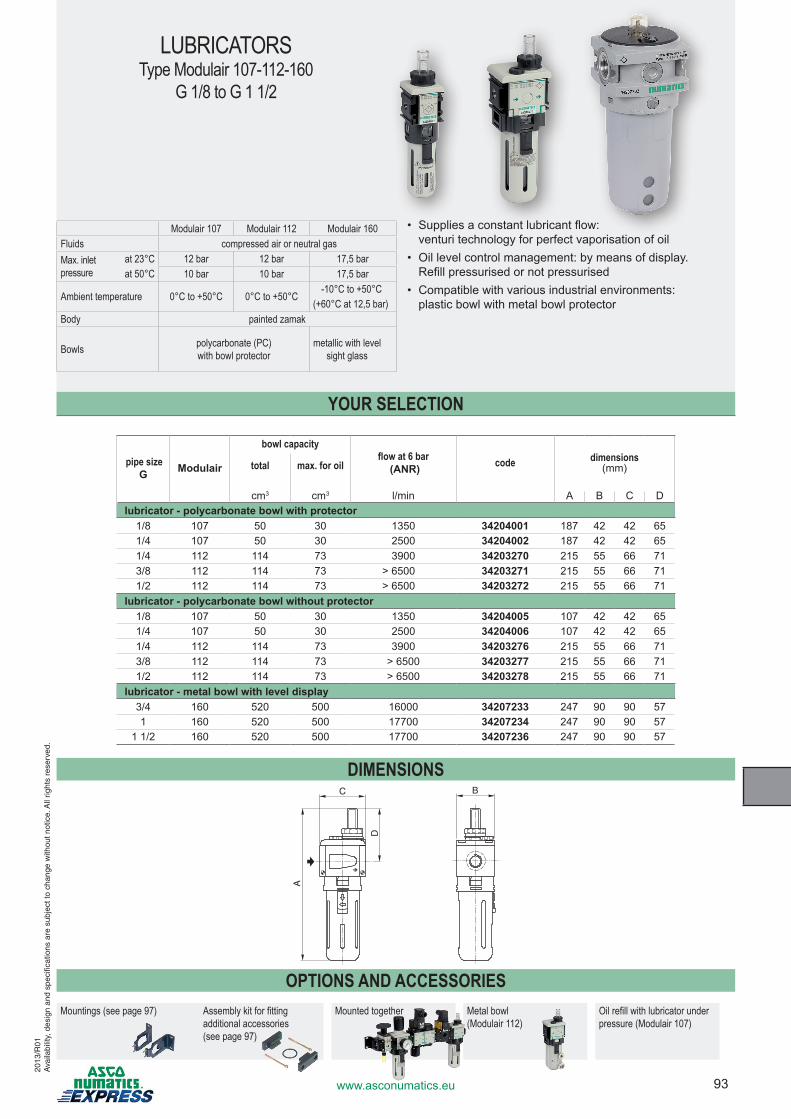
93www.asconumatics.eu
LUBRICATORSType Modulair 107-112-160
G 1/8 to G 1 1/2
Modulair 107 Modulair 112 Modulair 160Fluids compressed air or neutral gasMax. inlet pressure
at 23°C 12 bar 12 bar 17,5 barat 50°C 10 bar 10 bar 17,5 bar
Ambient temperature 0°C to +50°C 0°C to +50°C-10°C to +50°C
(+60°C at 12,5 bar)Body painted zamak
Bowls polycarbonate (PC) with bowl protector
metallic with level sight glass
• Supplies a constant lubricant flow: venturi technology for perfect vaporisation of oil
• Oil level control management: by means of display. Refill pressurised or not pressurised
• Compatible with various industrial environments: plastic bowl with metal bowl protector
YOUR SELECTION
pipe size G Modulair
bowl capacityflow at 6 bar
(ANR) code dimensions (mm)total max. for oil
cm3 cm3 l/min A B C Dlubricator - polycarbonate bowl with protector
1/8 107 50 30 1350 34204001 187 42 42 651/4 107 50 30 2500 34204002 187 42 42 651/4 112 114 73 3900 34203270 215 55 66 713/8 112 114 73 > 6500 34203271 215 55 66 711/2 112 114 73 > 6500 34203272 215 55 66 71
lubricator - polycarbonate bowl without protector1/8 107 50 30 1350 34204005 107 42 42 651/4 107 50 30 2500 34204006 107 42 42 651/4 112 114 73 3900 34203276 215 55 66 713/8 112 114 73 > 6500 34203277 215 55 66 711/2 112 114 73 > 6500 34203278 215 55 66 71
lubricator - metal bowl with level display3/4 160 520 500 16000 34207233 247 90 90 571 160 520 500 17700 34207234 247 90 90 57
1 1/2 160 520 500 17700 34207236 247 90 90 57
DIMENSIONSC
D
A
B
OPTIONS AND ACCESSORIESMountings (see page 97) Assembly kit for fitting
additional accessories (see page 97)
Mounted together Metal bowl(Modulair 112)
Oil refill with lubricator under pressure (Modulair 107)
2013
/R01
Ava
ilabi
lity,
des
ign
and
spec
ifica
tions
are
sub
ject
to c
hang
e w
ithou
t not
ice.
All
right
s re
serv
ed.
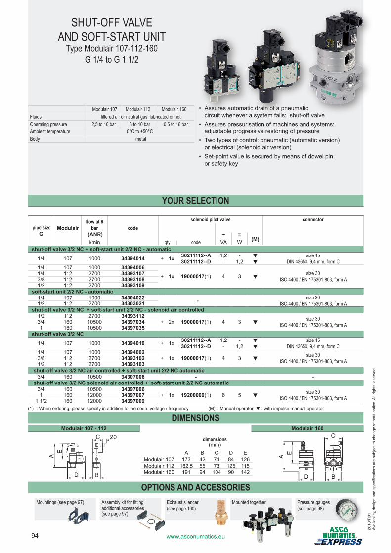
94 www.asconumatics.eu
YOUR SELECTION
pipe size G
Modulairflow at 6
bar (ANR)
codesolenoid pilot valve connector
~ =(M)l/min qty code VA W
shut-off valve 3/2 NC + soft-start unit 2/2 NC - automatic
1/4 107 1000 34394014 + 1x 30211112--A30211112--D
1,2-
-1,2
▼▼
size 15DIN 43650, 9,4 mm, form C
1/4 107 1000 34394006+ 1x 19000017(1) 4 3 ▼
size 30ISO 4400 / EN 175301-803, form A
1/4 112 2700 343931073/8 112 2700 343931081/2 112 2700 34393109
soft-start unit 2/2 NC - automatic1/4 107 1000 34304022 - size 30
ISO 4400 / EN 175301-803, form A1/2 112 2700 34303021shut-off valve 3/2 NC + soft-start unit 2/2 NC - solenoid air controlled
1/2 112 2700 34393112+ 2x 19000017(1) 4 3 ▼
size 30ISO 4400 / EN 175301-803, form A3/4 160 10500 34397034
1 160 10500 34397035shut-off valve 3/2 NC
1/4 107 1000 34394010 + 1x 30211112--A30211112--D
1,2-
-1,2
▼▼
size 15DIN 43650, 9,4 mm, form C
1/4 107 1000 34394002+ 1x 19000017(1) 4 3 ▼
size 30ISO 4400 / EN 175301-803, form A3/8 112 2700 34393102
1/2 112 2700 34393103shut-off valve 3/2 NC air controlled + soft-start unit 2/2 NC automatic
3/4 160 10500 34307006 - -shut-off valve 3/2 NC solenoid air controlled + soft-start unit 2/2 NC automatic
3/4 160 10500 34397006+ 1x 19200009(1) 6 5 ▼
size 30ISO 4400 / EN 175301-803, form A1 160 12000 34397007
1 1/2 160 12000 34397009(1) : When ordering, please specify in addition to the code: voltage / frequency (M) : Manual operator ▼ : with impulse manual operator
DIMENSIONSModulair 107 - 112 Modulair 160
AE
D B
20C
AE
D B
C
OPTIONS AND ACCESSORIESMountings (see page 97) Assembly kit for fitting
additional accessories (see page 97)
Exhaust silencer (see page 100)
Mounted together Pressure gauges (see page 98)
SHUT-OFF VALVE AND SOFT-START UNIT
Type Modulair 107-112-160G 1/4 to G 1 1/2
• Assures automatic drain of a pneumatic circuit whenever a system fails: shut-off valve
• Assures pressurisation of machines and systems: adjustable progressive restoring of pressure
• Two types of control: pneumatic (automatic version) or electrical (solenoid air version)
• Set-point value is secured by means of dowel pin, or safety key
dimensions (mm)
A B C D EModulair 107 173 42 74 84 126Modulair 112 182,5 55 73 125 115Modulair 160 191 94 104 90 142
Modulair 107 Modulair 112 Modulair 160Fluids filtered air or neutral gas, lubricated or notOperating pressure 2,5 to 10 bar 3 to 10 bar 0,5 to 16 barAmbient temperature 0°C to +50°CBody metal
2013
/R01
Ava
ilabi
lity,
des
ign
and
spec
ifica
tions
are
sub
ject
to c
hang
e w
ithou
t not
ice.
All
right
s re
serv
ed.
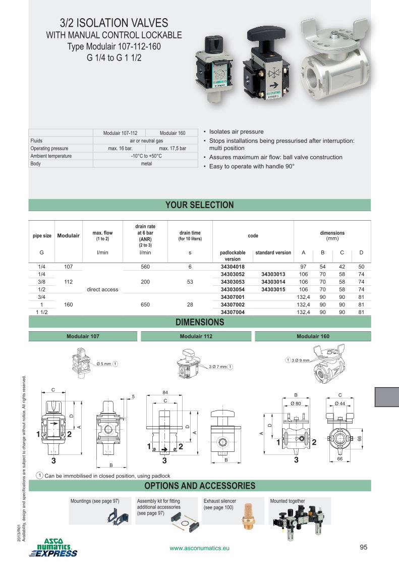
95www.asconumatics.eu
YOUR SELECTION
pipe size Modulair max. flow (1 to 2)
drain rate at 6 bar (ANR) (2 to 3)
drain time (for 10 liters) code dimensions
(mm)
G l/min l/min s padlockable version
standard version A B C D
1/4 107
direct access
560 6 34304018 97 54 42 501/4
112 200 5334303052 34303013 106 70 58 74
3/8 34303053 34303014 106 70 58 741/2 34303054 34303015 106 70 58 743/4
160 650 2834307001 132,4 90 90 81
1 34307002 132,4 90 90 811 1/2 34307004 132,4 90 90 81
DIMENSIONSModulair 107 Modulair 112 Modulair 160
OPTIONS AND ACCESSORIESMountings (see page 97) Assembly kit for fitting
additional accessories (see page 97)
Exhaust silencer (see page 100)
Mounted together
3/2 ISOLATION VALVESWITH MANUAL CONTROL LOCKABLE
Type Modulair 107-112-160G 1/4 to G 1 1/2
Modulair 107-112 Modulair 160Fluids air or neutral gasOperating pressure max. 16 bar. max. 17,5 barAmbient temperature -10°C to +50°CBody metal
• Isolates air pressure• Stops installations being pressurised after interruption:
multi position• Assures maximum air flow: ball valve construction• Easy to operate with handle 90°
1 Can be immobilised in closed position, using padlock
3 Ø 9 mm1
3 Ø 7 mm 1Ø 5 mm 1
B
C
D
A
5
1 2
3 B
C
84
D
A
1 2
3
Ø 44
C
Ø 80
B
D
A
66
66
1 2
3
2013
/R01
Ava
ilabi
lity,
des
ign
and
spec
ifica
tions
are
sub
ject
to c
hang
e w
ithou
t not
ice.
All
right
s re
serv
ed.
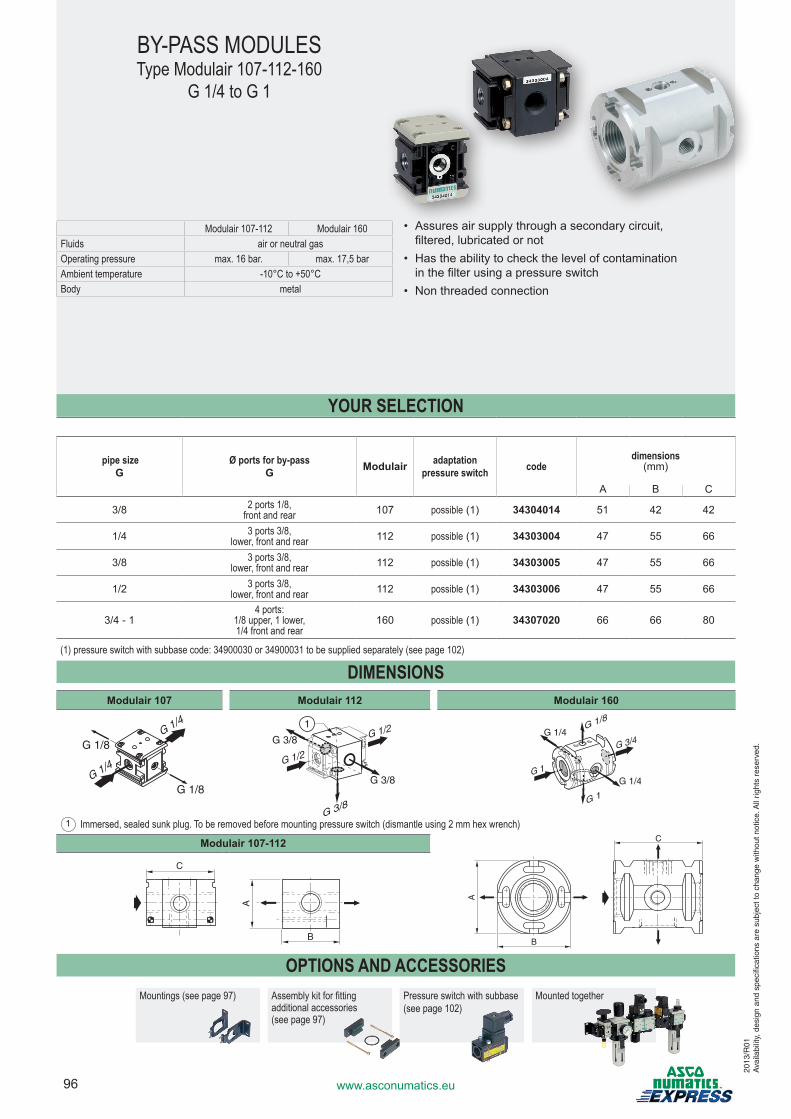
96 www.asconumatics.eu
Modulair 107-112 Modulair 160Fluids air or neutral gasOperating pressure max. 16 bar. max. 17,5 barAmbient temperature -10°C to +50°CBody metal
YOUR SELECTION
pipe size G
Ø ports for by-pass G Modulair adaptation
pressure switch codedimensions
(mm)
A B C
3/8 2 ports 1/8, front and rear 107 possible (1) 34304014 51 42 42
1/4 3 ports 3/8, lower, front and rear 112 possible (1) 34303004 47 55 66
3/8 3 ports 3/8, lower, front and rear 112 possible (1) 34303005 47 55 66
1/2 3 ports 3/8, lower, front and rear 112 possible (1) 34303006 47 55 66
3/4 - 14 ports:
1/8 upper, 1 lower, 1/4 front and rear
160 possible (1) 34307020 66 66 80
(1) pressure switch with subbase code: 34900030 or 34900031 to be supplied separately (see page 102)
DIMENSIONSModulair 107 Modulair 112 Modulair 160
G 1/4
G 1/8
G 1/8
G 1/4
G 3/8
G 1/2
G 3/8
G 3/8
G 1/21
G 1
G 1/8
G 1
G 1/4
G 1/4
G 3/4
Modulair 107-112
B
A
C
B
C
A
OPTIONS AND ACCESSORIESMountings (see page 97) Assembly kit for fitting
additional accessories (see page 97)
Pressure switch with subbase (see page 102)
Mounted together
BY-PASS MODULESType Modulair 107-112-160
G 1/4 to G 1
• Assures air supply through a secondary circuit, filtered, lubricated or not
• Has the ability to check the level of contamination in the filter using a pressure switch
• Non threaded connection
1 Immersed, sealed sunk plug. To be removed before mounting pressure switch (dismantle using 2 mm hex wrench)
2013
/R01
Ava
ilabi
lity,
des
ign
and
spec
ifica
tions
are
sub
ject
to c
hang
e w
ithou
t not
ice.
All
right
s re
serv
ed.
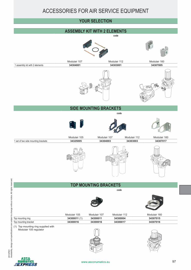
97www.asconumatics.eu
ACCESSORIES FOR AIR SERVICE EQUIPMENT
ASSEMBLY KIT WITH 2 ELEMENTScode
Modulair 107 Modulair 112 Modulair 1601 assembly kit with 2 elements 34304001 34303001 34307005
SIDE MOUNTING BRACKETScode
Modulair 105 Modulair 107 Modulair 112 Modulair 1601 set of two side mounting brackets 34325005 34304003 34303003 34307017
TOP MOUNTING BRACKETScode
Modulair 105 Modulair 107 Modulair 112 Modulair 160Top mounting ring 34300011 (1) 34300011 34300004 34307015Top mounting bracket 34300016 34300016 34300017 34307016
(1) Top mounting ring supplied with Modulair 105 regulator
YOUR SELECTION
2013
/R01
Ava
ilabi
lity,
des
ign
and
spec
ifica
tions
are
sub
ject
to c
hang
e w
ithou
t not
ice.
All
right
s re
serv
ed.
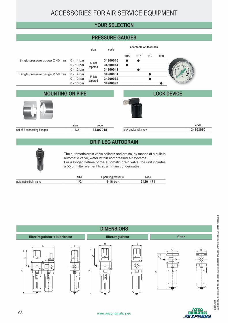
98 www.asconumatics.eu
PRESSURE GAUGES
size codeadaptable on Modulair
105 107 112 160Single pressure gauge Ø 40 mm 0 - 4 bar
R1/8tapered
34300015 ● ●
0 - 10 bar 34300014 ●
0 - 12 bar 34300041 ●
Single pressure gauge Ø 50 mm 0 - 4 barR1/8
tapered
34200061 ●
0 - 12 bar 34200062 ●
0 - 16 bar 34200997 ●
MOUNTING ON PIPE LOCK DEVICE
size codeset of 2 connecting flanges 1 1/2 34307018
DRIP LEG AUTODRAIN
The automatic drain valve collects and drains, by means of a built-in automatic valve, water within compressed air systems.For a longer lifetime of the automatic drain valve, the unit includes a 55 µm filter element to strain main condensates.
size Operating pressure codeautomatic drain valve 1/2 1-16 bar 34201471
YOUR SELECTION
DIMENSIONSfilter/regulator + lubricator filter/regulator filter
A
C B
D
A
C
D
B
C B
AD
ACCESSORIES FOR AIR SERVICE EQUIPMENT
2013
/R01
Ava
ilabi
lity,
des
ign
and
spec
ifica
tions
are
sub
ject
to c
hang
e w
ithou
t not
ice.
All
right
s re
serv
ed.
codelock device with key 34303050
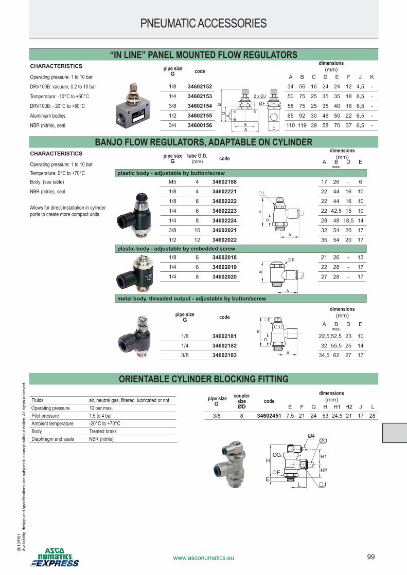
99www.asconumatics.eu
“IN LINE” PANEL MOUNTED FLOW REGULATORSCHARACTERISTICS pipe size
G codedimensions
(mm)Operating pressure: 1 to 10 bar A B C D E F J K
DRV100B: vacuum, 0,2 to 10 bar 1/8 34602152 34 56 16 24 24 12 4,5 -
Temperature: -10°C to +60°C 1/4 34602153 50 75 25 35 35 18 6,5 -
DRV100B: - 20°C to +80°C 3/8 34602154 58 75 25 35 40 18 6,5 -
Aluminium bodies 1/2 34602155 65 92 30 46 50 22 6,5 -
NBR (nitrile), seal 3/4 34600156 110 119 39 58 70 37 6,5 -
BANJO FLOW REGULATORS, ADAPTABLE ON CYLINDERCHARACTERISTICS pipe size
Gtube O.D.
(mm) codedimensions
(mm)Operating pressure: 1 to 10 bar A B D E
max.
Temperature: 0°C to +70°C plastic body - adjustable by button/screwBody: (see table) M5 4 34602188 17 26 - 6
NBR (nitrile), seal 1/8 4 34602221 22 44 16 10
Allows for direct installation in cylinder ports to create more compact units
1/8 6 34602222 22 44 16 10
1/4 6 34602223 22 42,5 15 10
1/4 8 34602224 28 48 18,5 14
3/8 10 34602021 32 54 20 17
1/2 12 34602022 35 54 20 17plastic body - adjustable by embedded screw
1/8 6 34602018 21 26 - 13
1/4 6 34602019 22 28 - 17
1/4 8 34602020 27 28 - 17
metal body, threaded output - adjustable by button/screw
pipe sizeG code
dimensions(mm)
A B D Emax.
1/8 34602181 22,5 52,5 23 10
1/4 34602182 32 55,5 25 14
3/8 34602183 34,5 62 27 17
Ø F
CEA
DB
==
2 x ØJ
K
E
A
D
B
A
BE
E
A
D
B
PNEUMATIC ACCESSORIES20
13/R
01A
vaila
bilit
y, d
esig
n an
d sp
ecifi
catio
ns a
re s
ubje
ct to
cha
nge
with
out n
otic
e. A
ll rig
hts
rese
rved
. ORIENTABLE CYLINDER BLOCKING FITTING
pipe sizeG
coupler sizeØD
codedimensions
(mm)E F G H H1 H2 J L
3/8 8 34602451 7,5 21 24 53 24,5 21 17 28
F
L
HH1
H2
EJ
ØD
ØG
Ø4
Fluids air, neutral gas, filtered, lubricated or notOperating pressure 10 bar max.Pilot pressure 1.5 to 4 barAmbient temperature -20°C to +70°CBody Treated brassDiaphragm and seals NBR (nitrile)
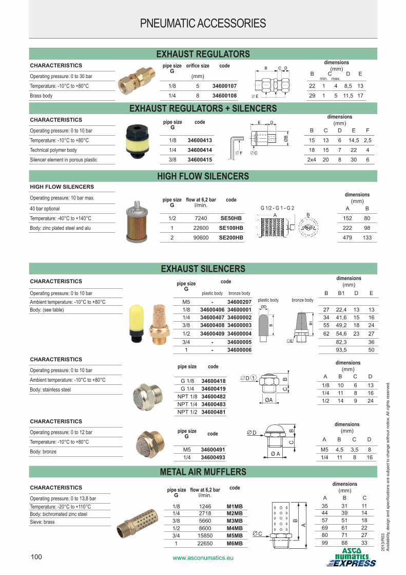
100 www.asconumatics.eu
EXHAUST REGULATORSCHARACTERISTICS pipe size
Gorifice size code dimensions
(mm)Operating pressure: 0 to 30 bar (mm) B C D E
min. max.
Temperature: -10°C to +80°C 1/8 5 34600107 22 1 4 8,5 13
Brass body 1/4 8 34600108 29 1 5 11,5 17
EXHAUST REGULATORS + SILENCERSCHARACTERISTICS pipe size
Gcode
F C
E D
ØB
dimensions(mm)
Operating pressure: 0 to 10 bar B C D E F
Temperature: -10°C to +80°C 1/8 34600413 15 13 6 14,5 2,5
Technical polymer body 1/4 34600414 18 15 7 22 4
Silencer element in porous plastic 3/8 34600415 2x4 20 8 30 6
HIGH FLOW SILENCERSHIGH FLOW SILENCERS
A BG 1/2 - G 1 - G 2
Operating pressure: 10 bar max. pipe sizeG
flow at 6,2 barl/min.
codedimensions
(mm)40 bar optional A B
Temperature: -40°C to +140°C 1/2 7240 SE50HB 152 80
Body: zinc plated steel and alu 1 22600 SE100HB 222 98
2 90600 SE200HB 479 133
EXHAUST SILENCERSCHARACTERISTICS pipe size
Gcode dimensions
(mm)Operating pressure: 0 to 10 bar plastic body bronze body B B1 D EAmbient temperature: -10°C to +80°C M5 - 34600207Body: (see table) 1/8 34600406 34600001 27 22,4 13 13
1/4 34600407 34600002 34 41,6 15 163/8 34600408 34600003 55 49,2 18 241/2 34600409 34600004 62 54,6 23 273/4 - 34600005 82,3 361 - 34600006 93,5 50
pipe sizeG code D
Ø A
CB
dimensions(mm)
A B C D
M5 34600491 M5 4,5 3,5 81/4 34600493 1/4 11 8 16
PNEUMATIC ACCESSORIES
ØD
B
E
B1
plastic body bronze body
D
E
B C
pipe size code
D
CB
ØA
1G 1/8 34600418G 1/4 34600419
NPT 1/8 34600482NPT 1/4 34600483NPT 1/2 34600481
CHARACTERISTICS
Operating pressure: 0 to 12 bar
Temperature: -10°C to +80°C
Body: bronze
CHARACTERISTICS
Operating pressure: 0 to 10 bar
Ambient temperature: -10°C to +80°C
Body: stainless steel
dimensions(mm)
A B C D1/8 10 6 131/4 11 8 161/2 14 9 24
2013
/R03
Ava
ilabi
lity,
des
ign
and
spec
ifica
tions
are
sub
ject
to c
hang
e w
ithou
t not
ice.
All
right
s re
serv
ed.
CHARACTERISTICS
Operating pressure: 0 to 13,8 barTemperature: -20°C to +110°CBody: bichromated zinc steelSieve: brass
pipe sizeG
flow at 6,2 barl/min.
code
1/8 1246 M1MB1/4 2718 M2MB3/8 5660 M3MB1/2 8600 M4MB3/4 15850 M5MB1 22650 M6MB
dimensions(mm)
A B C35 31 1144 39 1457 51 1869 61 2280 71 2799 88 33
C
A
B
METAL AIR MUFFLERS
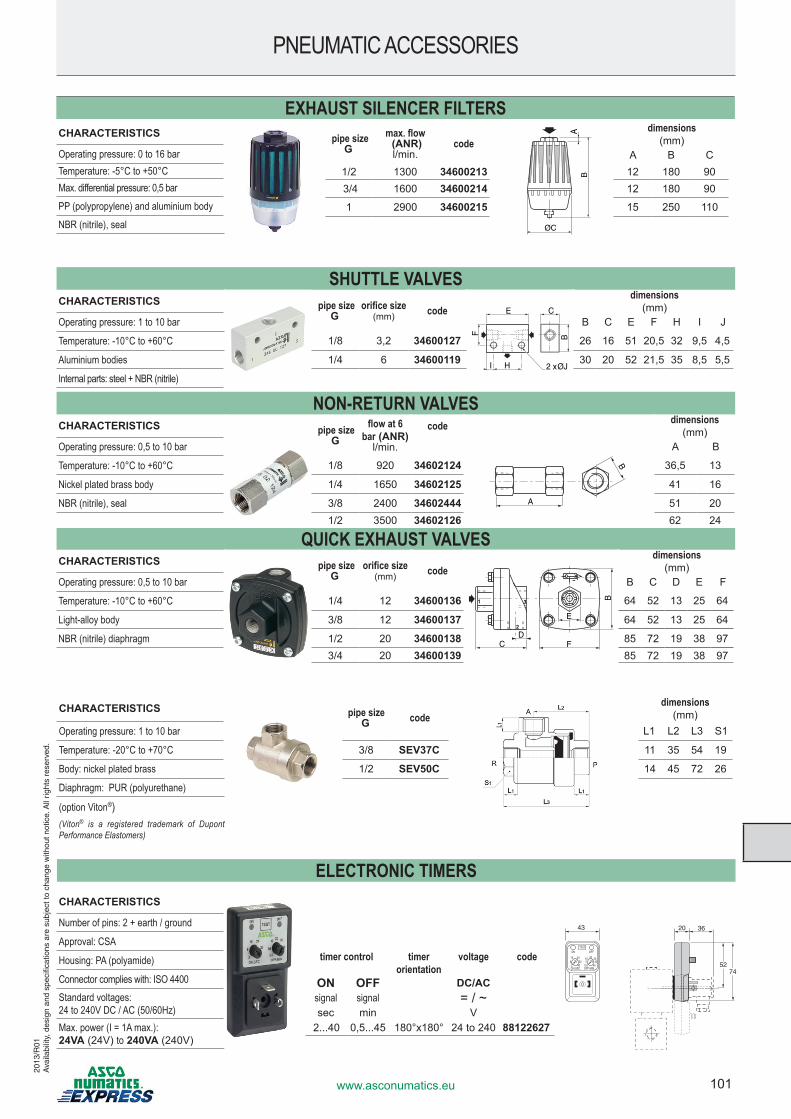
101www.asconumatics.eu
CHARACTERISTICS pipe sizeG code
dimensions(mm)
Operating pressure: 1 to 10 bar L1 L2 L3 S1
Temperature: -20°C to +70°C 3/8 SEV37C 11 35 54 19
Body: nickel plated brass 1/2 SEV50C 14 45 72 26
Diaphragm: PUR (polyurethane)
(option Viton®)(Viton® is a registered trademark of Dupont Performance Elastomers)
SHUTTLE VALVESCHARACTERISTICS pipe size
Gorifice size
(mm) code E
H
BF
I 2 x ØJ
C
dimensions(mm)
Operating pressure: 1 to 10 bar B C E F H I J
Temperature: -10°C to +60°C 1/8 3,2 34600127 26 16 51 20,5 32 9,5 4,5
Aluminium bodies 1/4 6 34600119 30 20 52 21,5 35 8,5 5,5
Internal parts: steel + NBR (nitrile)
NON-RETURN VALVESCHARACTERISTICS pipe size
Gflow at 6
bar (ANR)l/min.
code dimensions(mm)
Operating pressure: 0,5 to 10 bar
A
B
A B
Temperature: -10°C to +60°C 1/8 920 34602124 36,5 13
Nickel plated brass body 1/4 1650 34602125 41 16
NBR (nitrile), seal 3/8 2400 34602444 51 201/2 3500 34602126 62 24
QUICK EXHAUST VALVESCHARACTERISTICS pipe size
Gorifice size
(mm) code
F
31
2
DC
BE
dimensions(mm)
Operating pressure: 0,5 to 10 bar B C D E F
Temperature: -10°C to +60°C 1/4 12 34600136 64 52 13 25 64
Light-alloy body 3/8 12 34600137 64 52 13 25 64
NBR (nitrile) diaphragm 1/2 20 34600138 85 72 19 38 973/4 20 34600139 85 72 19 38 97
PNEUMATIC ACCESSORIES20
13/R
01A
vaila
bilit
y, d
esig
n an
d sp
ecifi
catio
ns a
re s
ubje
ct to
cha
nge
with
out n
otic
e. A
ll rig
hts
rese
rved
.
EXHAUST SILENCER FILTERS pipe size
Gmax. flow (ANR)l/min.
codedimensions
(mm)A B C
1/2 1300 34600213 12 180 90 3/4 1600 34600214 12 180 90
1 2900 34600215 15 250 110
CHARACTERISTICS
Operating pressure: 0 to 16 barTemperature: -5°C to +50°CMax. differential pressure: 0,5 barPP (polypropylene) and aluminium bodyNBR (nitrile), seal
AB
ØC
ELECTRONIC TIMERS
ON:SEC. OFF:MIN.2
816 24
3240
ON OFF
0,5510 30
4045
TEST
20
43 20
5274
36
timer control timer orientation
voltage code
ON OFF DC/ACsignal signal = / ~sec min V
2...40 0,5...45 180°x180° 24 to 240 88122627
CHARACTERISTICS
Number of pins: 2 + earth / ground
Approval: CSA
Housing: PA (polyamide)
Connector complies with: ISO 4400Standard voltages: 24 to 240V DC / AC (50/60Hz)Max. power (I = 1A max.): 24VA (24V) to 240VA (240V)

102 www.asconumatics.eu
ADJUSTABLE SUBBASE MOUNTED OR G1/4 PRESSURE SWITCHESVisualisation and electrical protection without with
Fluids air, neutral gas, filtered, lubricated or notRegulation range see belowHysteresis 0,4 bar / 1 barShut-off capability 5 A - 250 V resistive 2 A - 24 V DC resistiveTemperature -10°C to +60°C 0°C to +60°CElectrical connection ISO 4400 / EN 175301-803, form AMax. voltage 250 V AC/DC 24 V DCDegree of protection IP65Body PC (polycarbonate)Seals NBR (nitrile)
Regulation range codeThreaded bodywith side pneumatic connection, threaded G1/4 0,5 to 10 bar 34900018
with side pneumatic connection, threaded G1/4 0,2 to 6 bar 34900015
with side pneumatic connection, threaded G1/4, with status indicators and electrical protection 0,5 to 10 bar 34900019
Subbase mounted
with subbased mounted pneumatic connections 0,5 to 10 bar 34900030
with subbase mounted pneumatic connections, with status indicators and electrical protection 0,5 to 10 bar 34900031
adjustable vacuum switch
with side pneumatic connection, tapped G1/4 0,5 to 10 bar 34900012
all versions threaded body G1/4 subbase
30 20
16
7981
30
62
1
3
5 4
2
G1/4Ø 8
PNEUMATIC ACCESSORIES
Version with status indicators and electrical protection
1 pressure set screw (3mm hex screw)2 2 mounting holes, Ø 5,5 mm3 ISO 4400 connector, 4 terminals,
rotatable through 90° x 90°4 non-rotatable connector5 label holder
2013
/R01
Ava
ilabi
lity,
des
ign
and
spec
ifica
tions
are
sub
ject
to c
hang
e w
ithou
t not
ice.
All
right
s re
serv
ed.
PNEUMATIC INDICATOR
colour code
red 34600130yellow 34600131
31
22,554
31,5
M22 x 100
1
2
1
24
1 Angle of vision 180°2 Instant fittings for flexible tube Ø 4 O.D.
CHARACTERISTICSFluids air, neutral gas, filtered, lubricated or not
Operating pressure 2 to 8 bar
Ambient temperature +5°C to +70°C
Angle of vision 180°
Lens PC (polycarbonate)
Body and collar POM (polyacetal)
Nut Brass
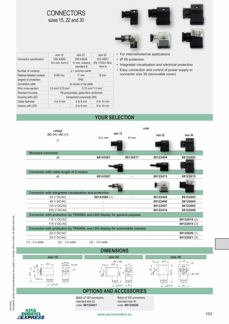
103www.asconumatics.eu
size 15 size 22 size 30Connector specification DIN 43650,
9,4 mm, form CDIN 43650,
11 mm, industry standard B
ISO 4400 / EN 175301-803,
form ANumber of contacts 2 + common earthDistance between contacts 9,4/8 mm 11 mm 18 mmDegree of protection IP65Connection cable by screw or by cableWire cross-section 0,5 mm2/ 0,75 mm2 0,75 mm2/1,5 mm2
Standard housing PA (polyamide), glass-fibre reinforcedHousing with LED transparent polyamide (PA)Cable diameter 4 to 6 mm 6 to 8 mm 6 to 10 mmVersion with LED - 6 to 8 mm 8 to 10 mm
voltage DC (=) / AC (~)
codesize 15 size 22 size 30
9,4 mm 8 mmV
Standard connectorall 88143581 88130211 88122404 88122602
Connector with cable length of 2 metersall 88143567 - 88122413 88122612
Connector with integrated visualisation and protection24 V DC/AC 88143580 (1) - 88122405 8812260348 V DC/AC - 88122406 88122604115 V DC/AC - 88122407 88122605230 V DC/AC - 88122410 88122608
Connector with protection by TRANSIL and LED display for general purpose115 V DC/AC 88122618 (2) 115 V DC/AC 88122619 (3)
Connector with protection by TRANSIL and LED display for automobile industry24 V DC/AC 88122620 (1)24 V DC/AC 88122621 (3)
(1) : 2 m cable (2) : 3 m cable (3) : 5 m cable
DIMENSIONSsize 15 size 22 size 30
2816,59,4/8
M3
34
16
2,5
2
90° x 90°
Ø 4-6
a
a 33
31M
3
50
23
11
12
4
180° x 180°
Ø 6-8
a
a
38
30
M3
52
Ø 6-10 30
18
1 2 90° x 90°
4 a
a
OPTIONS AND ACCESSORIESBatch of 100 connectors, standard size 22 code: 88122421
Batch of 100 connectors, standard size 30 code: 88122636
CONNECTORSsizes 15, 22 and 30
• For internal/external applications• IP 65 protection• Integrated visualisation and electrical protection• Easy connection and control of power supply to
connector size 30 (removable cover)
YOUR SELECTION
2013
/R01
Ava
ilabi
lity,
des
ign
and
spec
ifica
tions
are
sub
ject
to c
hang
e w
ithou
t not
ice.
All
right
s re
serv
ed.
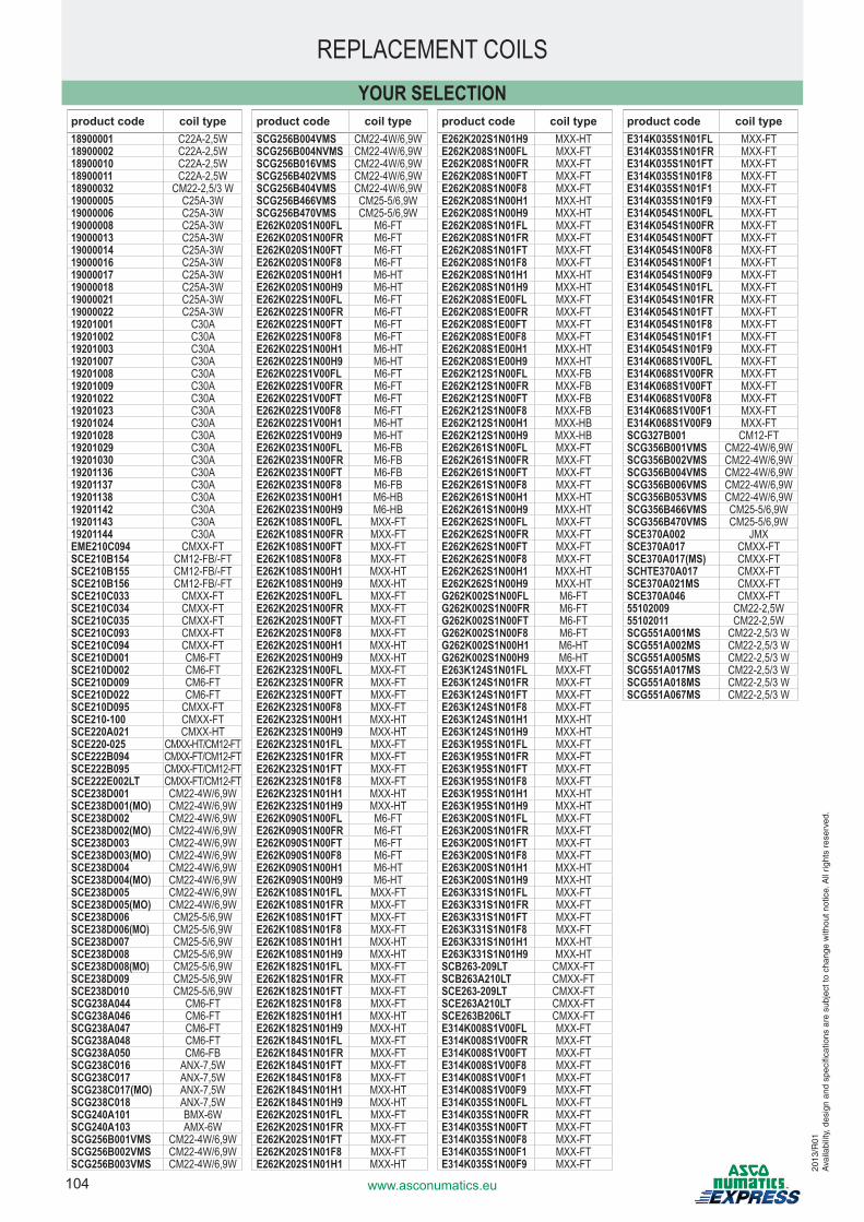
104 www.asconumatics.eu
REPLACEMENT COILS
product code coil type18900001 C22A-2,5W18900002 C22A-2,5W18900010 C22A-2,5W18900011 C22A-2,5W18900032 CM22-2,5/3 W19000005 C25A-3W19000006 C25A-3W19000008 C25A-3W19000013 C25A-3W19000014 C25A-3W19000016 C25A-3W19000017 C25A-3W19000018 C25A-3W19000021 C25A-3W19000022 C25A-3W19201001 C30A19201002 C30A19201003 C30A19201007 C30A19201008 C30A19201009 C30A19201022 C30A19201023 C30A19201024 C30A19201028 C30A19201029 C30A19201030 C30A19201136 C30A19201137 C30A19201138 C30A19201142 C30A19201143 C30A19201144 C30AEME210C094 CMXX-FTSCE210B154 CM12-FB/-FTSCE210B155 CM12-FB/-FTSCE210B156 CM12-FB/-FTSCE210C033 CMXX-FTSCE210C034 CMXX-FTSCE210C035 CMXX-FTSCE210C093 CMXX-FTSCE210C094 CMXX-FTSCE210D001 CM6-FTSCE210D002 CM6-FTSCE210D009 CM6-FTSCE210D022 CM6-FTSCE210D095 CMXX-FTSCE210-100 CMXX-FTSCE220A021 CMXX-HTSCE220-025 CMXX-HT/CM12-FTSCE222B094 CMXX-FT/CM12-FTSCE222B095 CMXX-FT/CM12-FTSCE222E002LT CMXX-FT/CM12-FTSCE238D001 CM22-4W/6,9WSCE238D001(MO) CM22-4W/6,9WSCE238D002 CM22-4W/6,9WSCE238D002(MO) CM22-4W/6,9WSCE238D003 CM22-4W/6,9WSCE238D003(MO) CM22-4W/6,9WSCE238D004 CM22-4W/6,9WSCE238D004(MO) CM22-4W/6,9WSCE238D005 CM22-4W/6,9WSCE238D005(MO) CM22-4W/6,9WSCE238D006 CM25-5/6,9WSCE238D006(MO) CM25-5/6,9WSCE238D007 CM25-5/6,9WSCE238D008 CM25-5/6,9WSCE238D008(MO) CM25-5/6,9WSCE238D009 CM25-5/6,9WSCE238D010 CM25-5/6,9WSCG238A044 CM6-FTSCG238A046 CM6-FTSCG238A047 CM6-FTSCG238A048 CM6-FTSCG238A050 CM6-FBSCG238C016 ANX-7,5WSCG238C017 ANX-7,5WSCG238C017(MO) ANX-7,5WSCG238C018 ANX-7,5WSCG240A101 BMX-6WSCG240A103 AMX-6WSCG256B001VMS CM22-4W/6,9WSCG256B002VMS CM22-4W/6,9WSCG256B003VMS CM22-4W/6,9W
product code coil typeSCG256B004VMS CM22-4W/6,9WSCG256B004NVMS CM22-4W/6,9WSCG256B016VMS CM22-4W/6,9WSCG256B402VMS CM22-4W/6,9WSCG256B404VMS CM22-4W/6,9WSCG256B466VMS CM25-5/6,9WSCG256B470VMS CM25-5/6,9WE262K020S1N00FL M6-FTE262K020S1N00FR M6-FTE262K020S1N00FT M6-FTE262K020S1N00F8 M6-FTE262K020S1N00H1 M6-HTE262K020S1N00H9 M6-HTE262K022S1N00FL M6-FTE262K022S1N00FR M6-FTE262K022S1N00FT M6-FTE262K022S1N00F8 M6-FTE262K022S1N00H1 M6-HTE262K022S1N00H9 M6-HTE262K022S1V00FL M6-FTE262K022S1V00FR M6-FTE262K022S1V00FT M6-FTE262K022S1V00F8 M6-FTE262K022S1V00H1 M6-HTE262K022S1V00H9 M6-HTE262K023S1N00FL M6-FBE262K023S1N00FR M6-FBE262K023S1N00FT M6-FBE262K023S1N00F8 M6-FBE262K023S1N00H1 M6-HBE262K023S1N00H9 M6-HBE262K108S1N00FL MXX-FTE262K108S1N00FR MXX-FTE262K108S1N00FT MXX-FTE262K108S1N00F8 MXX-FTE262K108S1N00H1 MXX-HTE262K108S1N00H9 MXX-HTE262K202S1N00FL MXX-FTE262K202S1N00FR MXX-FTE262K202S1N00FT MXX-FTE262K202S1N00F8 MXX-FTE262K202S1N00H1 MXX-HTE262K202S1N00H9 MXX-HTE262K232S1N00FL MXX-FTE262K232S1N00FR MXX-FTE262K232S1N00FT MXX-FTE262K232S1N00F8 MXX-FTE262K232S1N00H1 MXX-HTE262K232S1N00H9 MXX-HTE262K232S1N01FL MXX-FTE262K232S1N01FR MXX-FTE262K232S1N01FT MXX-FTE262K232S1N01F8 MXX-FTE262K232S1N01H1 MXX-HTE262K232S1N01H9 MXX-HTE262K090S1N00FL M6-FTE262K090S1N00FR M6-FTE262K090S1N00FT M6-FTE262K090S1N00F8 M6-FTE262K090S1N00H1 M6-HTE262K090S1N00H9 M6-HTE262K108S1N01FL MXX-FTE262K108S1N01FR MXX-FTE262K108S1N01FT MXX-FTE262K108S1N01F8 MXX-FTE262K108S1N01H1 MXX-HTE262K108S1N01H9 MXX-HTE262K182S1N01FL MXX-FTE262K182S1N01FR MXX-FTE262K182S1N01FT MXX-FTE262K182S1N01F8 MXX-FTE262K182S1N01H1 MXX-HTE262K182S1N01H9 MXX-HTE262K184S1N01FL MXX-FTE262K184S1N01FR MXX-FTE262K184S1N01FT MXX-FTE262K184S1N01F8 MXX-FTE262K184S1N01H1 MXX-HTE262K184S1N01H9 MXX-HTE262K202S1N01FL MXX-FTE262K202S1N01FR MXX-FTE262K202S1N01FT MXX-FTE262K202S1N01F8 MXX-FTE262K202S1N01H1 MXX-HT
product code coil typeE262K202S1N01H9 MXX-HTE262K208S1N00FL MXX-FTE262K208S1N00FR MXX-FTE262K208S1N00FT MXX-FTE262K208S1N00F8 MXX-FTE262K208S1N00H1 MXX-HTE262K208S1N00H9 MXX-HTE262K208S1N01FL MXX-FTE262K208S1N01FR MXX-FTE262K208S1N01FT MXX-FTE262K208S1N01F8 MXX-FTE262K208S1N01H1 MXX-HTE262K208S1N01H9 MXX-HTE262K208S1E00FL MXX-FTE262K208S1E00FR MXX-FTE262K208S1E00FT MXX-FTE262K208S1E00F8 MXX-FTE262K208S1E00H1 MXX-HTE262K208S1E00H9 MXX-HTE262K212S1N00FL MXX-FBE262K212S1N00FR MXX-FBE262K212S1N00FT MXX-FBE262K212S1N00F8 MXX-FBE262K212S1N00H1 MXX-HBE262K212S1N00H9 MXX-HBE262K261S1N00FL MXX-FTE262K261S1N00FR MXX-FTE262K261S1N00FT MXX-FTE262K261S1N00F8 MXX-FTE262K261S1N00H1 MXX-HTE262K261S1N00H9 MXX-HTE262K262S1N00FL MXX-FTE262K262S1N00FR MXX-FTE262K262S1N00FT MXX-FTE262K262S1N00F8 MXX-FTE262K262S1N00H1 MXX-HTE262K262S1N00H9 MXX-HTG262K002S1N00FL M6-FTG262K002S1N00FR M6-FTG262K002S1N00FT M6-FTG262K002S1N00F8 M6-FTG262K002S1N00H1 M6-HTG262K002S1N00H9 M6-HTE263K124S1N01FL MXX-FTE263K124S1N01FR MXX-FTE263K124S1N01FT MXX-FTE263K124S1N01F8 MXX-FTE263K124S1N01H1 MXX-HTE263K124S1N01H9 MXX-HTE263K195S1N01FL MXX-FTE263K195S1N01FR MXX-FTE263K195S1N01FT MXX-FTE263K195S1N01F8 MXX-FTE263K195S1N01H1 MXX-HTE263K195S1N01H9 MXX-HTE263K200S1N01FL MXX-FTE263K200S1N01FR MXX-FTE263K200S1N01FT MXX-FTE263K200S1N01F8 MXX-FTE263K200S1N01H1 MXX-HTE263K200S1N01H9 MXX-HTE263K331S1N01FL MXX-FTE263K331S1N01FR MXX-FTE263K331S1N01FT MXX-FTE263K331S1N01F8 MXX-FTE263K331S1N01H1 MXX-HTE263K331S1N01H9 MXX-HTSCB263-209LT CMXX-FTSCB263A210LT CMXX-FTSCE263-209LT CMXX-FTSCE263A210LT CMXX-FTSCE263B206LT CMXX-FTE314K008S1V00FL MXX-FTE314K008S1V00FR MXX-FTE314K008S1V00FT MXX-FTE314K008S1V00F8 MXX-FTE314K008S1V00F1 MXX-FTE314K008S1V00F9 MXX-FTE314K035S1N00FL MXX-FTE314K035S1N00FR MXX-FTE314K035S1N00FT MXX-FTE314K035S1N00F8 MXX-FTE314K035S1N00F1 MXX-FTE314K035S1N00F9 MXX-FT
product code coil typeE314K035S1N01FL MXX-FTE314K035S1N01FR MXX-FTE314K035S1N01FT MXX-FTE314K035S1N01F8 MXX-FTE314K035S1N01F1 MXX-FTE314K035S1N01F9 MXX-FTE314K054S1N00FL MXX-FTE314K054S1N00FR MXX-FTE314K054S1N00FT MXX-FTE314K054S1N00F8 MXX-FTE314K054S1N00F1 MXX-FTE314K054S1N00F9 MXX-FTE314K054S1N01FL MXX-FTE314K054S1N01FR MXX-FTE314K054S1N01FT MXX-FTE314K054S1N01F8 MXX-FTE314K054S1N01F1 MXX-FTE314K054S1N01F9 MXX-FTE314K068S1V00FL MXX-FTE314K068S1V00FR MXX-FTE314K068S1V00FT MXX-FTE314K068S1V00F8 MXX-FTE314K068S1V00F1 MXX-FTE314K068S1V00F9 MXX-FTSCG327B001 CM12-FTSCG356B001VMS CM22-4W/6,9WSCG356B002VMS CM22-4W/6,9WSCG356B004VMS CM22-4W/6,9WSCG356B006VMS CM22-4W/6,9WSCG356B053VMS CM22-4W/6,9WSCG356B466VMS CM25-5/6,9WSCG356B470VMS CM25-5/6,9WSCE370A002 JMXSCE370A017 CMXX-FTSCE370A017(MS) CMXX-FTSCHTE370A017 CMXX-FTSCE370A021MS CMXX-FTSCE370A046 CMXX-FT55102009 CM22-2,5W55102011 CM22-2,5WSCG551A001MS CM22-2,5/3 WSCG551A002MS CM22-2,5/3 WSCG551A005MS CM22-2,5/3 WSCG551A017MS CM22-2,5/3 WSCG551A018MS CM22-2,5/3 WSCG551A067MS CM22-2,5/3 W
YOUR SELECTION
2013
/R01
Ava
ilabi
lity,
des
ign
and
spec
ifica
tions
are
sub
ject
to c
hang
e w
ithou
t not
ice.
All
right
s re
serv
ed.
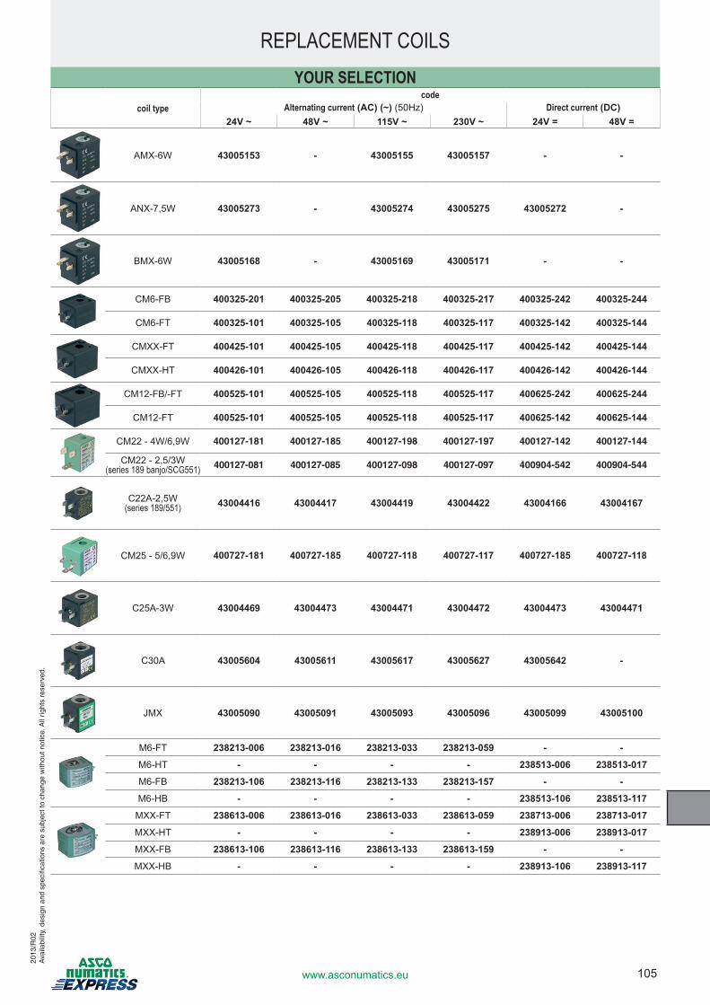
105www.asconumatics.eu
YOUR SELECTION
REPLACEMENT COILS
coil typecode
Alternating current (AC) (~) (50Hz) Direct current (DC)24V ~ 48V ~ 115V ~ 230V ~ 24V = 48V =
AMX-6W 43005153 - 43005155 43005157 - -
ANX-7,5W 43005273 - 43005274 43005275 43005272 -
BMX-6W 43005168 - 43005169 43005171 - -
CM6-FB 400325-201 400325-205 400325-218 400325-217 400325-242 400325-244
CM6-FT 400325-101 400325-105 400325-118 400325-117 400325-142 400325-144
CMXX-FT 400425-101 400425-105 400425-118 400425-117 400425-142 400425-144
CMXX-HT 400426-101 400426-105 400426-118 400426-117 400426-142 400426-144
CM12-FB/-FT 400525-101 400525-105 400525-118 400525-117 400625-242 400625-244
CM12-FT 400525-101 400525-105 400525-118 400525-117 400625-142 400625-144
CM22 - 4W/6,9W 400127-181 400127-185 400127-198 400127-197 400127-142 400127-144
CM22 - 2,5/3W(series 189 banjo/SCG551) 400127-081 400127-085 400127-098 400127-097 400904-542 400904-544
C22A-2,5W(series 189/551) 43004416 43004417 43004419 43004422 43004166 43004167
CM25 - 5/6,9W 400727-181 400727-185 400727-118 400727-117 400727-185 400727-118
C25A-3W 43004469 43004473 43004471 43004472 43004473 43004471
C30A 43005604 43005611 43005617 43005627 43005642 -
JMX 43005090 43005091 43005093 43005096 43005099 43005100
M6-FT 238213-006 238213-016 238213-033 238213-059 - -
M6-HT - - - - 238513-006 238513-017
M6-FB 238213-106 238213-116 238213-133 238213-157 - -
M6-HB - - - - 238513-106 238513-117
MXX-FT 238613-006 238613-016 238613-033 238613-059 238713-006 238713-017
MXX-HT - - - - 238913-006 238913-017
MXX-FB 238613-106 238613-116 238613-133 238613-159 - -
MXX-HB - - - - 238913-106 238913-117
2013
/R02
Ava
ilabi
lity,
des
ign
and
spec
ifica
tions
are
sub
ject
to c
hang
e w
ithou
t not
ice.
All
right
s re
serv
ed.
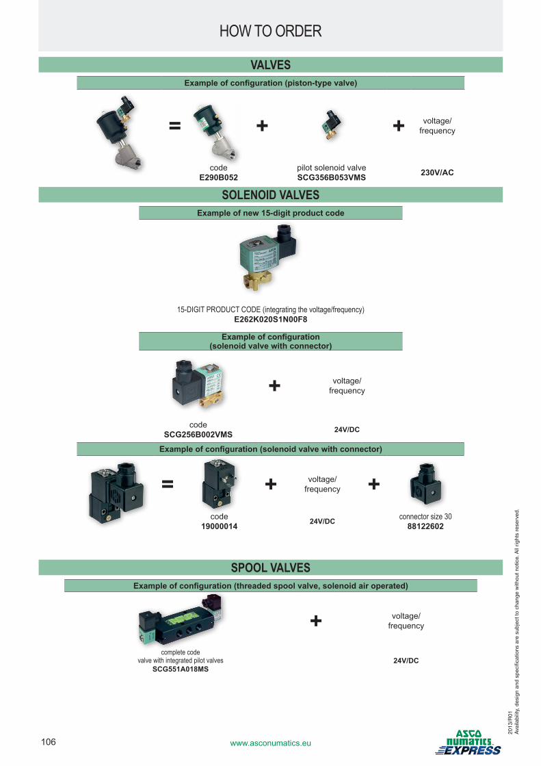
106 www.asconumatics.eu
VALVESExample of configuration (piston-type valve)
= + + voltage/frequency
codeE290B052
pilot solenoid valveSCG356B053VMS 230V/AC
SOLENOID VALVESExample of new 15-digit product code
15-DIGIT PRODUCT CODE (integrating the voltage/frequency)E262K020S1N00F8
Example of configuration (solenoid valve with connector)
+ voltage/frequency
codeSCG256B002VMS 24V/DC
Example of configuration (solenoid valve with connector)
= + voltage/frequency +
code19000014 24V/DC connector size 30
88122602
SPOOL VALVESExample of configuration (threaded spool valve, solenoid air operated)
+ voltage/frequency
complete codevalve with integrated pilot valves
SCG551A018MS24V/DC
HOW TO ORDER
2013
/R01
Ava
ilabi
lity,
des
ign
and
spec
ifica
tions
are
sub
ject
to c
hang
e w
ithou
t not
ice.
All
right
s re
serv
ed.
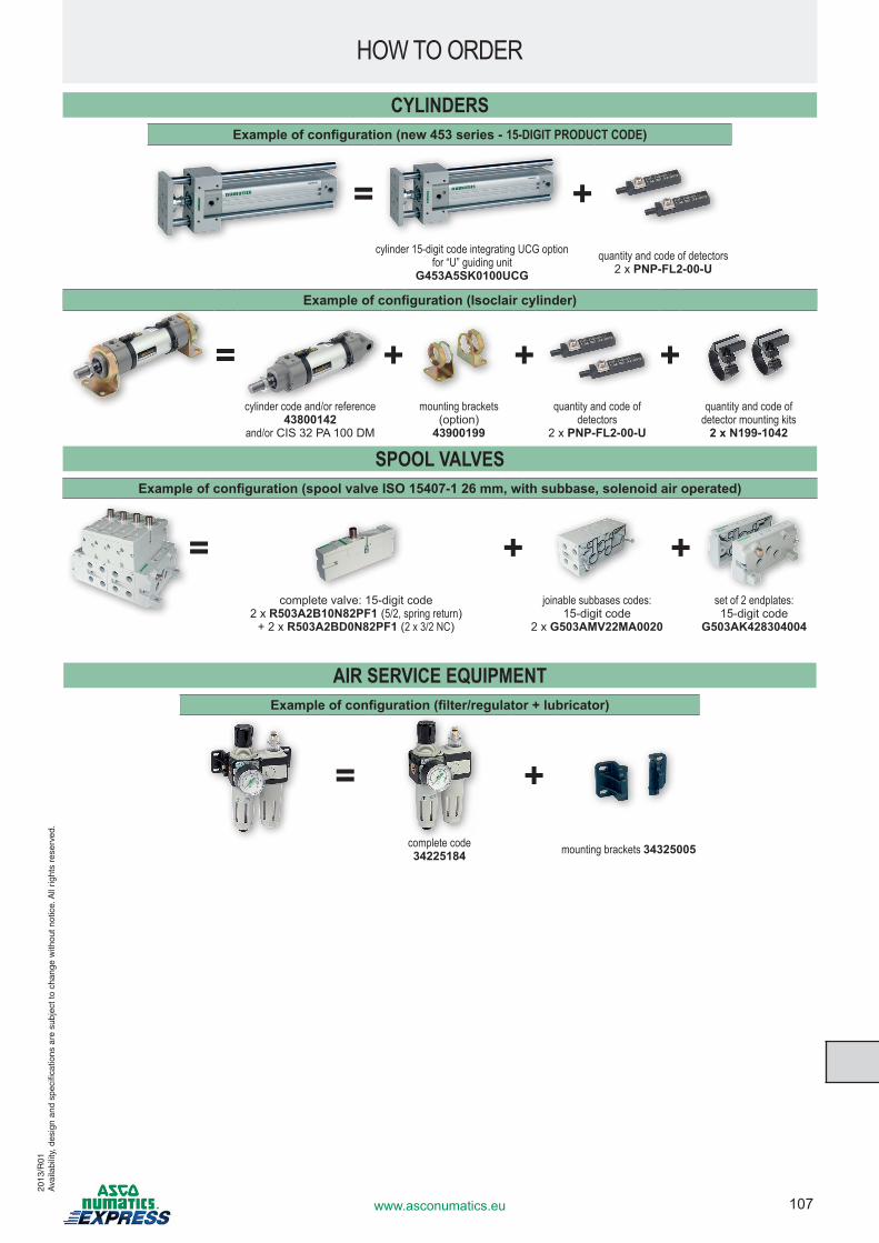
107www.asconumatics.eu
HOW TO ORDER
CYLINDERSExample of configuration (new 453 series - 15-DIGIT PRODUCT CODE)
= +cylinder 15-digit code integrating UCG option
for “U” guiding unit G453A5SK0100UCG
quantity and code of detectors2 x PNP-FL2-00-U
Example of configuration (Isoclair cylinder)
= + + +cylinder code and/or reference
43800142 and/or CIS 32 PA 100 DM
mounting brackets (option)
43900199
quantity and code of detectors
2 x PNP-FL2-00-U
quantity and code of detector mounting kits
2 x N199-1042
SPOOL VALVESExample of configuration (spool valve ISO 15407-1 26 mm, with subbase, solenoid air operated)
= + +complete valve: 15-digit code
2 x R503A2B10N82PF1 (5/2, spring return)+ 2 x R503A2BD0N82PF1 (2 x 3/2 NC)
joinable subbases codes:15-digit code
2 x G503AMV22MA0020
set of 2 endplates:15-digit code
G503AK428304004
AIR SERVICE EQUIPMENTExample of configuration (filter/regulator + lubricator)
= +complete code34225184 mounting brackets 34325005
2013
/R01
Ava
ilabi
lity,
des
ign
and
spec
ifica
tions
are
sub
ject
to c
hang
e w
ithou
t not
ice.
All
right
s re
serv
ed.
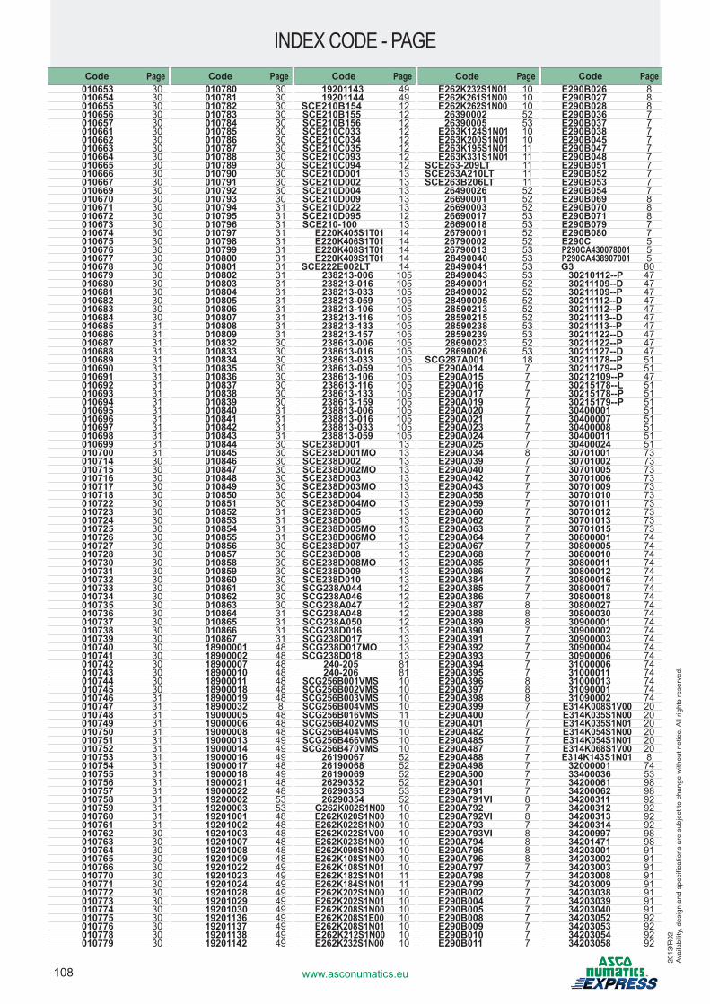
108 www.asconumatics.eu
INDEX CODE - PAGE
2013
/R02
Ava
ilabi
lity,
des
ign
and
spec
ifica
tions
are
sub
ject
to c
hang
e w
ithou
t not
ice.
All
right
s re
serv
ed.
Code Page010653 30010654 30010655 30010656 30010657 30010661 30010662 30010663 30010664 30010665 30010666 30010667 30010669 30010670 30010671 30010672 30010673 30010674 30010675 30010676 30010677 30010678 30010679 30010680 30010681 30010682 30010683 30010684 30010685 31010686 31010687 31010688 31010689 31010690 31010691 31010692 31010693 31010694 31010695 31010696 31010697 31010698 31010699 31010700 31010714 30010715 30010716 30010717 30010718 30010722 30010723 30010724 30010725 30010726 30010727 30010728 30010730 30010731 30010732 30010733 30010734 30010735 30010736 30010737 30010738 30010739 30010740 30010741 30010742 30010743 30010744 30010745 30010746 31010747 31010748 31010749 31010750 31010751 31010752 31010753 31010754 31010755 31010756 31010757 31010758 31010759 31010760 31010761 31010762 30 010763 30010764 30 010765 30010766 30 010770 30010771 30 010772 30010773 30 010774 30010775 30 010776 30010778 30010779 30
Code Page010780 30010781 30010782 30010783 30010784 30010785 30010786 30010787 30010788 30010789 30010790 30010791 30010792 30 010793 30010794 31 010795 31 010796 31 010797 31 010798 31 010799 31 010800 31 010801 31 010802 31 010803 31 010804 31 010805 31 010806 31 010807 31 010808 31 010809 31 010832 30010833 30010834 30010835 30010836 30010837 30010838 30010839 30010840 31010841 31010842 31010843 31010844 30010845 30010846 30010847 30010848 30010849 30010850 30010851 30010852 31 010853 31 010854 31 010855 31 010856 30010857 30010858 30010859 30010860 30010861 30010862 30010863 30010864 31010865 31010866 31010867 3118900001 48 18900002 48 18900007 4818900010 4818900011 4818900018 4818900019 4818900032 8 19000005 4819000006 4819000008 48 19000013 4919000014 49 19000016 4919000017 48 19000018 49 19000021 4819000022 4819200002 5319200003 5319201001 4819201002 4819201003 4819201007 4819201008 4819201009 4819201022 4919201023 4919201024 4919201028 4919201029 4919201030 4919201136 4919201137 4919201138 4919201142 49
Code Page19201143 4919201144 49
SCE210B154 12 SCE210B155 12 SCE210B156 12 SCE210C033 12 SCE210C034 12 SCE210C035 12 SCE210C093 12 SCE210C094 12 SCE210D001 13SCE210D002 13SCE210D004 13SCE210D009 13SCE210D022 13SCE210D095 12 SCE210-100 13
E220K405S1T01 14E220K406S1T01 14E220K408S1T01 14E220K409S1T01 14
SCE222E002LT 14238213-006 105238213-016 105238213-033 105238213-059 105238213-106 105238213-116 105238213-133 105238213-157 105238613-006 105238613-016 105238613-033 105238613-059 105238613-106 105238613-116 105238613-133 105238613-159 105238813-006 105238813-016 105238813-033 105238813-059 105
SCE238D001 13SCE238D001MO 13SCE238D002 13SCE238D002MO 13SCE238D003 13SCE238D003MO 13SCE238D004 13SCE238D004MO 13SCE238D005 13SCE238D006 13SCE238D005MO 13SCE238D006MO 13SCE238D007 13SCE238D008 13SCE238D008MO 13SCE238D009 13SCE238D010 13SCG238A044 12SCG238A046 12SCG238A047 12SCG238A048 12SCG238A050 12SCG238D016 13 SCG238D017 13SCG238D017MO 13SCG238D018 13
240-205 81240-206 81
SCG256B001VMS 10SCG256B002VMS 10 SCG256B003VMS 10SCG256B004VMS 10SCG256B016VMS 11 SCG256B402VMS 10SCG256B404VMS 10SCG256B466VMS 10SCG256B470VMS 10
26190067 5226190068 5226190069 5226290352 5226290353 5326290354 52
G262K002S1N00 10 E262K020S1N00 10E262K022S1N00 10 E262K022S1V00 10E262K023S1N00 10 E262K090S1N00 10E262K108S1N00 10 E262K108S1N01 10E262K182S1N01 11E262K184S1N01 11E262K202S1N00 10E262K202S1N01 10E262K208S1N00 10E262K208S1E00 10E262K208S1N01 10E262K212S1N00 10E262K232S1N00 10
Code PageE262K232S1N01 10E262K261S1N00 10E262K262S1N00 10
26390002 5226390005 53
E263K124S1N01 10E263K200S1N01 10E263K195S1N01 11E263K331S1N01 11
SCE263-209LT 11SCE263A210LT 11SCE263B206LT 11
26490026 5226690001 5226690003 5226690017 5326690018 5326790001 5226790002 5226790013 5328490040 5328490041 5328490043 5328490001 5228490002 5228490005 5228590213 5228590215 5228590238 5328590239 5328690023 5228690026 53
SCG287A001 18E290A014 7E290A015 7E290A016 7E290A017 7 E290A019 7E290A020 7E290A021 7E290A023 7 E290A024 7E290A025 7 E290A034 8 E290A039 7E290A040 7 E290A042 7E290A043 7 E290A058 7 E290A059 7E290A060 7 E290A062 7 E290A063 7E290A064 7 E290A067 7 E290A068 7E290A085 7 E290A086 7 E290A384 7E290A385 7 E290A386 7 E290A387 8 E290A388 8E290A389 8E290A390 7 E290A391 7 E290A392 7E290A393 7E290A394 7 E290A395 7E290A396 8E290A397 8E290A398 8E290A399 7E290A400 7 E290A401 7E290A482 7E290A485 7 E290A487 7E290A488 7 E290A498 7E290A500 7 E290A501 7E290A791 7 E290A791VI 8E290A792 7 E290A792VI 8E290A793 7E290A793VI 8E290A794 8 E290A795 8 E290A796 8 E290A797 7 E290A798 7E290A799 7 E290B002 7E290B004 7 E290B005 7E290B008 7 E290B009 7E290B010 7 E290B011 7
Code PageE290B026 8 E290B027 8 E290B028 8 E290B036 7E290B037 7E290B038 7E290B045 7E290B047 7E290B048 7E290B051 7E290B052 7E290B053 7E290B054 7E290B069 8E290B070 8 E290B071 8E290B079 7E290B080 7E290C 5P290CA430078001 5P290CA438907001 5G3 80
30210112--P 4730211109--D 4730211109--P 4730211112--D 4730211112--P 4730211113--D 4730211113--P 4730211122--D 4730211122--P 4730211127--D 4730211178--P 5130211179--P 5130212109--P 4730215178--L 5130215178--P 5130215179--P 5130400001 5130400007 5130400008 5130400011 5130400024 5130701001 7330701002 7330701005 7330701006 7330701009 7330701010 7330701011 7330701012 7330701013 7330701015 7330800001 74 30800005 74 30800010 74 30800011 7430800012 7430800016 74 30800017 74 30800018 74 30800027 74 30800030 74 30900001 74 30900002 74 30900003 74 30900004 74 30900006 7431000006 7431000011 7431000013 7431090001 7431090002 74
E314K008S1V00 20E314K035S1N00 20E314K035S1N01 20E314K054S1N00 20E314K054S1N01 20E314K068S1V00 20E314K143S1N01 8
32000001 7433400036 5334200061 98 34200062 98 34200311 9234200312 9234200313 9234200314 9234200997 98 34201471 98 34203001 9134203002 9134203003 9134203008 9134203009 9134203038 9134203039 9134203040 9134203052 9234203053 9234203054 9234203058 92
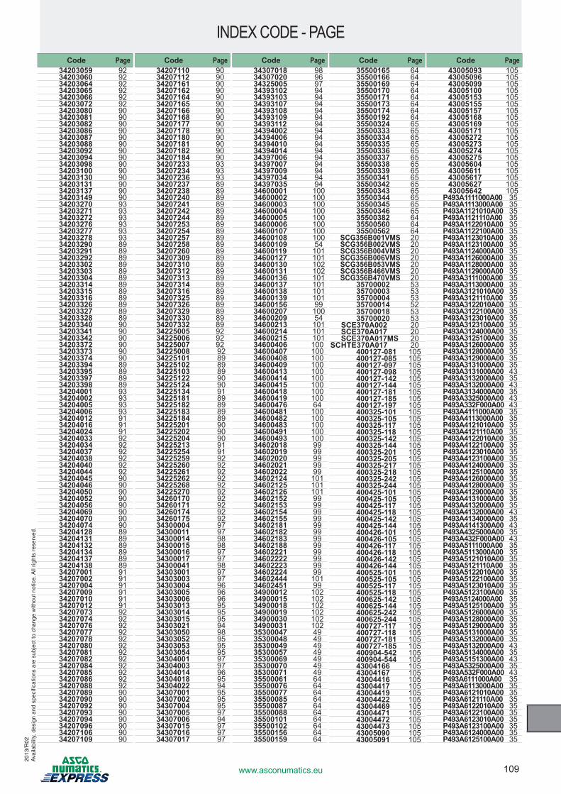
109www.asconumatics.eu
INDEX CODE - PAGE20
13/R
02A
vaila
bilit
y, d
esig
n an
d sp
ecifi
catio
ns a
re s
ubje
ct to
cha
nge
with
out n
otic
e. A
ll rig
hts
rese
rved
.
Code Page34203059 9234203060 9234203064 9234203065 9234203066 9234203072 9234203080 9034203081 9034203082 9034203086 9034203087 9034203088 9034203092 9034203094 9034203098 9034203100 9034203130 9034203131 9034203137 9034203149 9034203270 9334203271 93 34203272 93 34203276 9334203277 9334203278 9334203290 8934203291 89 34203292 8934203302 89 34203303 8934203304 89 34203314 8934203315 8934203316 89 34203326 8934203327 8934203328 89 34203340 9034203341 9034203342 9034203372 9034203373 9034203374 9034203394 8934203395 8934203397 8934203398 8934204001 93 34204002 93 34204005 93 34204006 93 34204012 91 34204016 9134204024 9134204033 9234204034 9234204037 9234204038 9234204040 9234204044 9234204045 9034204046 9034204050 90 34204052 9034204056 9034204069 9034204070 90 34204074 9034204128 8934204131 8934204132 8934204134 8934204137 8934204138 8934207001 91 34207002 91 34207004 9134207009 9134207010 9134207012 9134207073 9234207074 9234207076 9234207077 9234207078 9234207080 9234207081 9234207082 9234207084 9234207085 9234207086 9234207088 9234207089 9034207090 9034207092 9034207093 9034207094 9034207096 9034207106 9034207109 90
Code Page34207110 9034207112 9034207161 9034207162 9034207164 9034207165 9034207166 9034207168 9034207177 9034207178 9034207180 9034207181 9034207182 9034207184 9034207233 93 34207234 93 34207236 93 34207237 8934207238 8934207240 8934207241 8934207242 8934207244 8934207253 8934207254 8934207257 8934207258 8934207260 8934207309 8934207310 8934207312 8934207313 8934207314 8934207316 8934207325 8934207326 8934207329 8934207330 8934207332 8934225005 9234225006 9234225007 9234225008 9234225101 8934225102 8934225103 8934225122 9034225124 9034225134 9134225181 8934225182 8934225183 8934225184 89 34225201 9034225202 9034225204 9034225213 9134225254 9134225259 9234225260 9234225261 9234225262 9234225268 9234225270 9234260170 9234260171 9234260174 9234260175 9234300004 97 34300011 97 34300014 98 34300015 98 34300016 97 34300017 97 34300041 98 34303001 97 34303003 97 34303004 9634303005 9634303006 96 34303013 9534303014 9534303015 9534303021 9434303050 9834303052 9534303053 95 34303054 95 34304001 9734304003 97 34304014 96 34304018 9534304022 9434307001 95 34307002 95 34307004 95 34307005 97 34307006 94 34307015 9734307016 97 34307017 97
Code Page34307018 9834307020 96 34325005 97 34393102 94 34393103 94 34393107 9434393108 94 34393109 9434393112 94 34394002 9434394006 94 34394010 94 34394014 94 34397006 9434397007 94 34397009 9434397034 94 34397035 9434600001 100 34600002 100 34600003 100 34600004 100 34600005 100 34600006 100 34600107 100 34600108 100 34600109 5434600119 101 34600127 101 34600130 102 34600131 102 34600136 101 34600137 101 34600138 101 34600139 101 34600156 99 34600207 10034600209 54 34600213 101 34600214 101 34600215 101 34600406 10034600407 100 34600408 10034600409 100 34600413 10034600414 100 34600415 10034600418 100 34600419 100 34600476 6434600481 10034600482 100 34600483 100 34600491 10034600493 10034602018 99 34602019 99 34602020 99 34602021 99 34602022 99 34602124 101 34602125 101 34602126 101 34602152 99 34602153 99 34602154 99 34602155 99 34602181 99 34602182 99 34602183 99 34602188 99 34602221 99 34602222 99 34602223 99 34602224 99 34602444 10134602451 9934900012 10234900015 10234900018 10234900019 10234900030 10234900031 10235300047 49 35300048 49 35300049 49 35300057 49 35300069 49 35300070 49 35300071 49 35500061 64 35500076 64 35500077 64 35500085 6435500087 6435500088 64 35500101 64 35500102 64 35500156 6435500159 64
Code Page35500165 64 35500166 64 35500169 6435500170 64 35500171 64 35500173 64 35500174 6435500192 6435500324 6535500333 65 35500334 65 35500335 65 35500336 65 35500337 65 35500338 65 35500339 65 35500341 65 35500342 65 35500343 65 35500344 6535500345 65 35500346 6535500382 64 35500560 64 35500562 64
SCG356B001VMS 20SCG356B002VMS 20SCG356B004VMS 20SCG356B006VMS 20SCG356B053VMS 20SCG356B466VMS 20SCG356B470VMS 20
35700002 5335700003 5335700004 5335700014 5235700018 5335700020 53
SCE370A002 20SCE370A017 20 SCE370A017MS 20
SCHTE370A017 20400127-081 105400127-085 105400127-097 105400127-098 105400127-142 105400127-144 105400127-181 105400127-185 105400127-197 105400325-101 105400325-105 105400325-117 105400325-118 105400325-142 105400325-144 105400325-201 105400325-205 105400325-217 105400325-218 105400325-242 105400325-244 105400425-101 105400425-105 105400425-117 105400425-118 105400425-142 105400425-144 105400426-101 105400426-105 105400426-117 105400426-118 105400426-142 105400426-144 105 400525-101 105400525-105 105400525-117 105400525-118 105400625-142 105400625-144 105 400625-242 105400625-244 105400727-117 105400727-118 105400727-181 105400727-185 105 400904-542 105400904-544 105 43004166 10543004167 10543004416 10543004417 10543004419 105 43004422 10543004469 105 43004471 10543004472 10543004473 10543005090 10543005091 105
Code Page43005093 10543005096 10543005099 105 43005100 10543005153 105 43005155 10543005157 10543005168 10543005169 10543005171 105 43005272 10543005273 105 43005274 10543005275 10543005604 105 43005611 10543005617 105 43005627 10543005642 105
P493A1111000A00 35P493A1113000A00 35P493A1121010A00 35P493A1121110A00 35P493A1122010A00 35P493A1122100A00 35P493A1123010A00 35P493A1123100A00 35P493A1124000A00 35P493A1126000A00 35P493A1128000A00 35P493A1129000A00 35P493A3111000A00 35P493A3113000A00 35P493A3121010A00 35P493A3121110A00 35P493A3122010A00 35P493A3122100A00 35P493A3123010A00 35P493A3123100A00 35P493A3124000A00 35P493A3125100A00 35P493A3126000A00 35P493A3128000A00 35P493A3129000A00 35P493A3131000A00 35P493A3131000A00 43P493A3132000A00 35P493A3132000A00 43P493A3134000A00 35P493A3325000A00 43P493A332F000A00 43P493A4111000A00 35P493A4113000A00 35P493A4121010A00 35P493A4121110A00 35P493A4122010A00 35P493A4122100A00 35P493A4123010A00 35P493A4123100A00 35P493A4124000A00 35P493A4125100A00 35P493A4126000A00 35P493A4128000A00 35P493A4129000A00 35P493A4131000A00 35P493A4132000A00 35P493A4132000A00 43P493A4134000A00 35P493A4141300A00 43P493A4325000A00 35P493A432F000A00 43P493A5111000A00 35P493A5113000A00 35P493A5121010A00 35P493A5121110A00 35P493A5122010A00 35P493A5122100A00 35P493A5123010A00 35P493A5123100A00 35P493A5124000A00 35P493A5125100A00 35P493A5126000A00 35P493A5128000A00 35P493A5129000A00 35P493A5131000A00 35P493A5132000A00 35P493A5132000A00 43P493A5134000A00 35P493A5151300A00 43P493A5325000A00 35P493A532F000A00 43P493A6111000A00 35P493A6113000A00 35P493A6121010A00 35P493A6121110A00 35P493A6122010A00 35P493A6122100A00 35P493A6123010A00 35P493A6123100A00 35P493A6124000A00 35P493A6125100A00 35
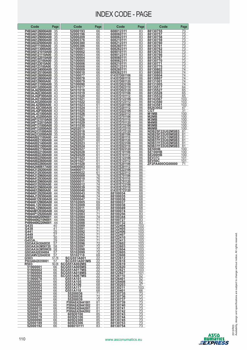
110 www.asconumatics.eu
INDEX CODE - PAGE
2013
/R03
Ava
ilabi
lity,
des
ign
and
spec
ifica
tions
are
sub
ject
to c
hang
e w
ithou
t not
ice.
All
right
s re
serv
ed.
Code PageP493A6126000A00 35P493A6128000A00 35P493A6129000A00 35P493A6129000A00 35P493A6325000A00 43P493A8111000A00 35P493A8113000A00 35P493A8121010A00 35P493A8121110A00 35P493A8122010A00 35P493A8122100A00 35P493A8123010A00 35P493A8123100A00 35P493A8124000A00 35P493A8125100A00 35P493A8126000A00 35P493A8128000A00 35P493A8129000A00 35P493A8131000A00 35P493A8132000A00 35P493AJ425000A00 43P493AJ42C000A00 43P493AJ42F000A00 43P493AJ431000A00 43P493AJ432000A00 43P493AL425000A00 43P493AL42C000A00 43P493AL42F000A00 43P493AL431000A00 43P493AL432000A00 43P493AP121010A00 35P493AP122010A00 35P493AP131000A00 35P493AP132000A00 35P493AQ131000A00 35P493AQ132000A00 35P494A0021100A00 44P494A0021300A00 44P494A0021400A00 44P494A0021500A00 44P494A0021700A00 44P494A0022100A00 44P494A0022300A00 44P494A0022500A00 44P494A0022600A00 44P494A0022800A00 44P494A2440617A00 44P494A3129200A00 44P494A3129300A00 44P494A3129600A00 44P494A4129300A00 44P494A4129600A00 44P494A5129200A00 44P494A5129600A00 44P494A6129600A00 44P494A8129200A00 44P494AJ129300A00 44P494AK129300A00 44P494AK129600A00 44P494AL129300A00 44P494AL129600A00 44P494AM129300A00 44P494AP129200A00 44P4994406200N001 44P4994406210N001 44P4994406220N001 44G435 40G438 41G441 25G449 27G450 30G453A... 29G503AA3A30A0030 57G503AA3A3M56Y20 58G503AA3A3M59W20 58G503AK428304004 57G503AMV220A0030 57G503 57-78P503AB428359001 57R503 56-58
51900001 6651900002 6651900004 6651900005 6651900078 6552000001 6652000002 6652000003 6652000004 6652000005 6652000006 6652000007 6652000008 6652000009 6652000010 6652000077 65 52000078 65 52000079 6552000090 6652000189 6652000192 66
Code Page52000193 6652000196 6652000209 6652000376 65 52000380 6652000386 6652100001 6652100002 6652100003 6652100004 6652100005 6652100006 6652100008 6652100009 6652100010 6652100077 65 52100078 65 52100079 6552100090 6654101017 60 54101018 60 54101019 60 54101020 60 54101021 60 54101022 60 54191023 61 54191024 61 54191025 61 54191026 61 54191027 61 54191028 61 54191029 61 54191030 61 54202017 60 54202018 6054202019 60 54202020 6054202021 60 54292023 6154292024 6154292027 6154292028 6154292029 6154391023 6154391027 6154391028 6154400003 6054490017 6154490022 6155000009 7655000010 7655000011 7655000012 7455000039 7655000040 7655000043 7655000046 7455000047 7455102005 6955102009 6955102011 6955102082 7155102083 7155102084 7455102086 7155102088 71 55102089 7155102091 7155102092 7155102093 7155102094 7155102095 7155102096 72 55102097 72 55102098 72 55102099 72 55102118 69
SCG551A001 22SCG551A001MS 22
SCG551A002MS 22 SCG551A005MS 22 SCG551A017MS 22 SCG551A018MS 22 SCG551A067MS 22
G551A101 22G551A105 68 G551A106 68 G551A117 68 G551A118 68
55200036 7155200038 7255200039 72
P599AE428441001 81P599AE428441002 81P599AE428442001 81P599AE428442002 81605D0100 85605D0106 85605D2300 85605D2306 85608010111 83
Code Page608012311 83608060111 83 608062311 83608210111 83 608212311 83608260111 83 608262311 83609010111 83 609012311 83609060111 83 609062311 83609210111 83 609212311 83609260111 83 609262311 83614357D001106 86614357D001110 86614357D001120 86614357D023106 86614357D023110 86614357D023120 86614357D101106 86614357D101112 86614357D123106 86614357D123112 86614357D201106 86614357D201112 86614357D223106 86614357D223112 86614357D701106 86614357D701110 86614357D701120 86614357D723106 86614357D723110 86614357D723120 86614357E001106 86614357E001110 86614357E001120 86614357E023106 86614357E023110 86614357E023120 86614357E101106 86614357E101112 86614357E123106 86614357E123112 86614357E201106 86614357E201112 86614357E223106 86614357E223112 86614357E701106 86614357E701110 86614357E701120 86614357E723106 86614357E723110 86614357E723120 8688100034 68 88100035 68 88100036 68 88100037 68 88100038 68 88100049 6888100074 6088100256 8388100344 6988100727 8388100732 8388122404 103 88122405 103 88122406 103 88122407 103 88122410 103 88122413 103 88122602 103 88122603 103 88122604 103 88122605 103 88122608 103 88122612 103 88122618 103 88122619 103 88122620 103 88122621 103 88122627 101 88126110 5288126401 5288128408 5288130203 4788130211 10388130401 6688130735 7388130736 7388130737 7388130739 7388130740 7388130741 7388130742 7388130743 7388130744 7388130745 7388130753 7388130754 73
Code Page88130755 7388130757 7388130758 7388130759 7388130760 7388130761 7388130762 7388130763 7388130766 7388130767 7388130770 7388130771 7388130775 7388130802 7488130803 7488130804 7488130807 7488131001 7488131005 7488135517 64 88135527 65 88135528 65 88135532 65 88143567 103 88143580 103 88143581 103 88263002 47 CGT 31M1MB 100M2MB 100M3MB 100M4MB 100M5MB 100M6MB 100NDB25F22U02MSB3 81NDB25F22U05MSB3 81NDB25F22U10MSB3 81NDB37F22U02MSB3 81NDB37F22U02MSB3 81NDB37F22U02MSB3 81SE50HB 100SE100HB 100SE200HB 100SEV37C 101SEV50C 101ZF2FA400OG00000 71


1312
92-3
57 -
1401