Embed Size (px)
Citation preview
Instruction Manual for AS380 Series Elevator Integrated Drive Controller
1

Instruction Manual for AS380 Series Elevator Integrated Drive Controller
2
AS 380 series elevator integrated drive controller
Publication Status: Standard
Product edition: V2.12
All Copyright© reserved by Shanghai STEP Electric
Corporation
All rights reserved
The information in this document is subject to change without prior
notice. No part of this document may in any form or by any means
(electronic, mechanical, micro-coping, photocopying, recording or
otherwise) be reproduced, stored in a retrial system or transmitted
without prior written permission from Shanghai STEP Electric
Corporation.
Instruction Manual for AS380 Series Elevator Integrated Drive Controller
3
Forward
AS380 series elevator integrated drive controller is the new generation of state-of-the-art
elevator-specific control and drive device. With full consideration of the safety & reliability of
elevator;inherent characteristic of elevator operation and specific feature of potential energy load
for elevator, AS380 series elevator integrated drive controller adopted advanced technology of
frequency control of motor speed and intelligent elevator control as well as the integration of
control & drive of elevator to make the further improvement of the product performance,
easy-to-use property and cost efficiency.
Abstract
The manual give an overall instruction about the installation, operation, parameter setting, daily
maintenance and trouble-shooting of AS380 series elevator integrated drive controller. The manual
can be used as the reference material in design of elevator system with AS380 series elevator
integrated drive controller, or also as the user manual for system installation, setting and
maintenance.
Please read the manual thoroughly to ensure the correct installation and operation of the elevator
integrated drive controller,
Reader
Users of elevator
Design engineers of elevator control
Engineering maintenance staffs
Customer technical support staffs
The manual is subject to update and amendment; please visit our company website for the update.
Our company website www.stepelectric.com
Instruction Manual for AS380 Series Elevator Integrated Drive Controller
4
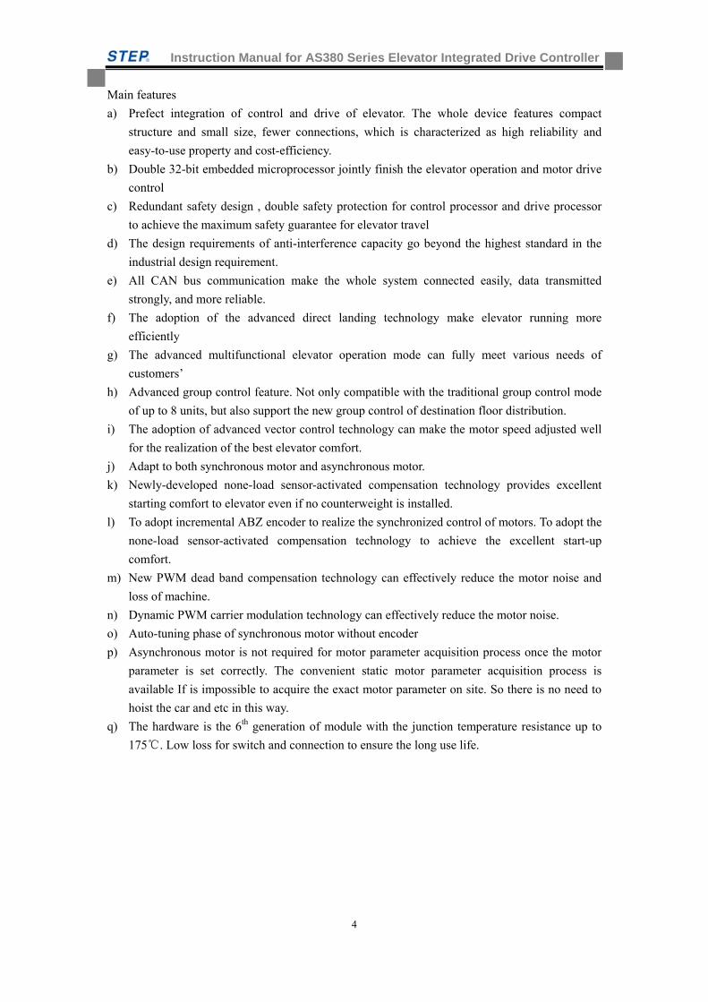
Main features
a) Prefect integration of control and drive of elevator. The whole device features compact
structure and small size, fewer connections, which is characterized as high reliability and
easy-to-use property and cost-efficiency.
b) Double 32-bit embedded microprocessor jointly finish the elevator operation and motor drive
control
c) Redundant safety design , double safety protection for control processor and drive processor
to achieve the maximum safety guarantee for elevator travel
d) The design requirements of anti-interference capacity go beyond the highest standard in the
industrial design requirement.
e) All CAN bus communication make the whole system connected easily, data transmitted
strongly, and more reliable.
f) The adoption of the advanced direct landing technology make elevator running more
efficiently
g) The advanced multifunctional elevator operation mode can fully meet various needs of
customers’
h) Advanced group control feature. Not only compatible with the traditional group control mode
of up to 8 units, but also support the new group control of destination floor distribution.
i) The adoption of advanced vector control technology can make the motor speed adjusted well
for the realization of the best elevator comfort.
j) Adapt to both synchronous motor and asynchronous motor.
k) Newly-developed none-load sensor-activated compensation technology provides excellent
starting comfort to elevator even if no counterweight is installed.
l) To adopt incremental ABZ encoder to realize the synchronized control of motors. To adopt the
none-load sensor-activated compensation technology to achieve the excellent start-up
comfort.
m) New PWM dead band compensation technology can effectively reduce the motor noise and
loss of machine.
n) Dynamic PWM carrier modulation technology can effectively reduce the motor noise.
o) Auto-tuning phase of synchronous motor without encoder
p) Asynchronous motor is not required for motor parameter acquisition process once the motor
parameter is set correctly. The convenient static motor parameter acquisition process is
available If is impossible to acquire the exact motor parameter on site. So there is no need to
hoist the car and etc in this way.
q) The hardware is the 6th generation of module with the junction temperature resistance up to
175. Low loss for switch and connection to ensure the long use life.
Instruction Manual for AS380 Series Elevator Integrated Drive Controller
5
Safety-related sign
The following safety-related sign are used in the manual, be sure to observe the instructions with
these signs
: Operation wrongly will cause death or serious injury to person
: Operation wrongly will cause injury to person and damage to equipment.
Important: the important content that need users’ attention and observation
Instruction Manual for AS380 Series Elevator Integrated Drive Controller
6
Table of contents
Chapter one: General knowledge of the integrated drive controller ...................... 11
1.1 scope of application ................................................................................................ 11
1.2 items in the cases ................................................................................................... 11
1.3 model description ................................................................................................... 11
1.4 integrated drive controller nameplate .................................................................... 12
1.5 Notice Items for safety ............................................................................................ 12
1.6 operation notice ..................................................................................................... 14
1.6.1 Brake resistor selection _____________________________________________________ 14
1.6.2 Absorber at the output side prohibited ________________________________________ 15
1.6.3 The application voltage of integrated device. ____________________________________ 15
1.6.4 Two‐phase input not allowed ________________________________________________ 15
1.6.5 Altitude and derated application _____________________________________________ 15
1.6.6 Synchronous sealing star delay _______________________________________________ 16
1.7 waste disposal ........................................................................................................ 16
1.7.1 Disposal of capacitors ______________________________________________________ 16
1.7.2 Disposal of plastic components _______________________________________________ 17
Chapter two: Model and Specification .................................................................. 18
2.1 Model of integrated drive controller ....................................................................... 18
2.2 The technical specification of integrated drive controller ........................................ 18
2.3 The installation dimensions and mass of the integrated drive controller ................. 24
2.4 Installation instructions .......................................................................................... 25
2.4.1 Product installation location _________________________________________________ 26
2.4.2 Product installation positioning and clearance requirements _______________________ 26
Chapter Three: product function ........................................................................... 28
3.1 Function list ............................................................................................................ 28
3.2 elevator operation function description and setting method ................................... 30
3.2.1 Standard function description ________________________________________________ 30
3.2.2 Optional function description ________________________________________________ 35
Chapter four: Wiring of Elevator Integrated Drive Controller ................................ 38
4.1 The connection between integrated drive controller and peripheral equipments .... 39
4.1.1 For typical terminal wiring diagram of elevator integrated drive controller. ____________ 39
4.2 Notice items for peripheral equipments connection ............................................... 39
4.2.1 Power supply _____________________________________________________________ 39
4.2.2 Breaker _________________________________________________________________ 40
4.2.3 AC reactor at the input side _________________________________________________ 40
4.2.4 Interference filter at the input side ____________________________________________ 40
Instruction Manual for AS380 Series Elevator Integrated Drive Controller
7
4.2.5 Main circuit output contactor ________________________________________________ 40
4.2.6 Interference filters at the output side. _________________________________________ 40
4.2.7 AC reactor at output side ___________________________________________________ 40
4.2.8 DC reactor _______________________________________________________________ 40
4.3 The technical requirements for wire arrangement of peripheral equipments of the
elevator integrated drive controller. ............................................................................. 41
4.3.1 The cable requirement of hoist way and accompanying cable arrangement ___________ 41
4.3.2 Method of Wiring Between Call board and TXV+、TXV‐、TXA+、TXA‐ _______________ 42
4.3.3Hoist way switch position ___________________________________________________ 43
4.3.4 Upper and Lower Leveling Inductor ___________________________________________ 44
4.4 main circuit terminal wiring .................................................................................... 45
4.4.1 The arrangement of main circuit terminal ______________________________________ 45
4.4.2 The main circuit terminal labeling and function description ________________________ 45
4.4.3 Main circuit wire specification _______________________________________________ 46
4.4.4 The main circuit composition ________________________________________________ 48
4.4.5 The detailed description of main circuit terminal wiring ___________________________ 48
4.5 anti‐interference measures. ................................................................................... 52
4.5.1 The specialized noise filter connected at the output side. __________________________ 52
4.5.2 Main circuit wiring arrangement _____________________________________________ 52
4.5.3 the better anti‐interference measure __________________________________________ 53
4.5.4 Relation between wiring length and carrier frequency. ____________________________ 53
4.6 Wiring of Control Circuit Terminals ......................................................................... 54
4.6.1 Layout of Control Circuit Terminals ___________________________________________ 54
4.6.2 Functional Description of Control Circuit Terminals _______________________________ 54
4.6.3 Dip switch setting method __________________________________________________ 57
4.6.4 Wire specification of control circuit ___________________________________________ 58
4.6.5 Notice items for control circuit terminal wiring __________________________________ 60
4.7 the wires of PG card terminal .................................................................................. 60
4.7.1 ABZ incremental 12v PG card ________________________________________________ 60
4.7.3 ABZ incremental 5V PG card _________________________________________________ 65
4.7.4 Endat absolute value PG card ________________________________________________ 67
4.7.5 Notice item for PG card terminal wiring ________________________________________ 69
Chapter Five :Operator ...................................................................................... 70 5.1.1 LED indicator light _________________________________________________________ 70
5.1.2 Function key _____________________________________________________________ 71
5.1.3 Operator handling _________________________________________________________ 72
5.1.4 graphic symbol of number and letter on LED screen ______________________________ 86
5.2 LCD handheld operator ........................................................................................... 87
5.2.1 LCD handheld operator introduction __________________________________________ 87
5.2.2 Handheld operator connection method ________________________________________ 88
5.2.3 Handheld operator function _________________________________________________ 89
5.2.4 Introduction to display interface of LCD hand‐held operator ________________________ 90
Instruction Manual for AS380 Series Elevator Integrated Drive Controller
8
Chapter 6 introduction to the supporting products ............................................100
6.1 Car top control board SM.02/H introduction ..........................................................101
6.1.1 Car top control panel SM.02/H outside view and installation dimension _____________ 101
6.1.2 Car top control panel SM 02/H ______________________________________________ 102
6.2 car top extension board SM09I0/B introduction ....................................................104
6.2.1 Car top extension board SM09IO/B outside view and installation dimension __________ 104
6.2.2 car top extension board SM09IO/B plug‐in and port definition introduction __________ 105
6.3 Car controller panel SM.02/G introduction .............................................................106
6.3.1 Car controller panel SM02/G outside view and installation dimension _______________ 106
6.3.2 Car control board SM.02/G plug‐in and port definition introduction _________________ 107
6.4 instruction control board SM‐03 ............................................................................109
6.4.1 Instruction control board SM‐03 outside view and installation dimension ____________ 110
6.4.2 Instruction controller board SM‐03 plug‐in and port definition introduction __________ 110
6.5 call & display control board ...................................................................................111
6.5.1 call &display control board SM‐04‐VRFS _______________________________________ 111
6.5.2 Call& display control board SM‐04‐HSC _______________________________________ 113
6.5.3 Call & Display Control Board SM‐04‐VHL ______________________________________ 115
6.5.4 Call & LCD Control Board SM‐04‐UL __________________________________________ 116
6.5.5 Car Call & LCD Control Board SM‐04‐VL _______________________________________ 118
6.5.6 In‐car SM‐04‐VL/B3 outside view and installation dimension ______________________ 121
6.5.7 Call& LED display control panel SM‐04‐VSD ____________________________________ 123
6.5.8 Call & LED display SM‐04‐VRJ _______________________________________________ 124
6.5.9 Miscellaneous (A List of Display Codes) _______________________________________ 125
6.6 SM‐GC board introduction .....................................................................................128
6.6.1 System structure _________________________________________________________ 128
6.6.2Basic Feature ____________________________________________________________ 128
6.6.3Main Functions ___________________________________________________________ 129
6.6.5 Overall adjustment principle ________________________________________________ 131
6.6.6 Treatment in special situation _______________________________________________ 132
6.6.7 detailed description of group controller _______________________________________ 132
6.6.8 Connection Diagram of Group Control System __________________________________ 136
Chapter 7 Parameter Table of Integrated Drive Controller ....................................143
7.1 F Parameter List .....................................................................................................143
7.2 Definition of function parameter ........................................................................... 157
Chapter 8 Elevator adjustment and setting instructions ....................................... 178
8.2 Check before Power on .......................................................................................... 182
8.3 Power on and Check .............................................................................................. 182
8.3.1 Confirmation before Power on ______________________________________________ 182
8.3.2 Checks after Power on ____________________________________________________ 183
Instruction Manual for AS380 Series Elevator Integrated Drive Controller
9
8.4 Configuration of System Basic Parameters and Self Study of Motor Parameters
184
8.4.1 Configuration of System Basic Parameters _____________________________________ 184
8.4.2 Motor Parameter Self Study ________________________________________________ 185
8.5 Test Run of Slow Car ..............................................................................................186
8.5.1 Inspection Operation of Engine Room and Preparations for Express Car _____________ 186
8.5.2 Car Top Inspection Operation _______________________________________________ 187
8.5.3 Check of CAN Communication Lines and Setting of 04 Board Address _______________ 188
8.5.4 Door Opening/Closing Adjustment ___________________________________________ 189
8.6 hoist way Self Study ...............................................................................................189
8.6.1 Hoist way Self Study Method _______________________________________________ 189
8.7 Express Car Operation ............................................................................................190
8.8 Adjust Elevator Comfort .........................................................................................193
8.8.1 Factors Relating to Elevator Comfort in Operation _______________________________ 193
8.8.2 Adjust Elevator Comfort ___________________________________________________ 194
8.9 Leveling Adjustment .............................................................................................. 202
8.10 Method for Adjusting Pre‐Load Weighing Compensation at Elevator Start ........... 208
8.10.1 Use of DTZZ‐III‐DC‐SC ____________________________________________________ 210
8.10.2 Use of non‐DTZZ‐III‐DC‐SC weighing device (F164 set to 1, 2, 5 or 6) to compensate or
adjust the start _______________________________________________________________ 211
8.10.3 Simple compensation by using light‐load and heavy‐load switch (F164 set to 4) ______ 211
8.11 The adjustment of other function ........................................................................212
Chapter 9: Faults and Solutions ............................................................................213
9.1 The fault analysis of the integrated device control system ......................................213
9.2 fault analysis of Integrated drive system ................................................................ 220
Chapter 10: Maintenance .....................................................................................228
10.1 Warranty ..........................................................................................................228
10.2 Product Checkup ..............................................................................................228
10.3 Routine Inspection ...........................................................................................229
10.4 Periodic Inspection ...........................................................................................229
Appendix A EMC Installation Guide .....................................................................231
A1 Noise Control .........................................................................................................231
A1.1 Noise Type ______________________________________________________________ 231
A1.2 Transmission Path _______________________________________________________ 231
A1.3 Basic Measures for Noise Suppression _______________________________________ 231
A2 Requirements on Cable Laying ................................................................................232
A2.1 Requirement on Cable Laying _______________________________________________ 232
Instruction Manual for AS380 Series Elevator Integrated Drive Controller
10
A2.2 Requirements on Cable Size ________________________________________________ 233
A2.3 Requirements on Shielded Cable _____________________________________________ 233
A2.4 Requirements on Installation of shielded cable _________________________________ 233
A3 Grounding Requirements .......................................................................................233
A3.1 Grounding Method _______________________________________________________ 233
A3.2 Precautions for Grounding Connection ________________________________________ 234
A4 Install Surge Absorption Device ........................................................................234
A5 Leakage Current and Countermeasures .............................................................235
A5.1 Ground Leakage Current ___________________________________________________ 235
A5.2 Line‐to‐Line Leakage Current ________________________________________________ 235
A6 Suppression of Radiated Emission .....................................................................236
A7 Guide for Use of Power line filter ......................................................................236
A7.1 Functions of Power line filter_______________________________________________ 236
A7.2 Precautions for Installation of Power Line Filter _________________________________ 237
A8 EMC Installation Zoning .................................................................................... 237
A9 Precautions for Electric Installation ...................................................................238
A10 EMC Conformity ...............................................................................................240
Appendix B Function Parameter, Fault List Summary ...........................................241
B.1 Function Parameter List .........................................................................................241
B.2 Fault Code And Analysis ..................................................................................... 255
Notice to customers ............................................................................................. 270
Instruction Manual for AS380 Series Elevator Integrated Drive Controller
11
Chapter one: General knowledge of the integrated drive controller
This chapter introduces the general information of AS380 series integrated drive controller,
including the voltage grade and adaptive motor capacity of the integrated device, and items
checkup in the cases. Besides, the chapter describes in detail the notice items during the process of
integrated device installation, wiring, operation, maintenance and disposal. Please read carefully
this chapter for the safe operation of the integrated device and prolonging of the service life.
1.1 scope of application
The voltage grade of AS380 series elevator integrated drive controller is 200V, 400V. AS380
series elevator integrated drive controller is both asynchronous motor and synchronous motor
compatible. The mating motor capacity is 1.1kW~75kW right now. the max floor single elevator
support is 64 floor. The max quantity of elevator group control is up to 8 units. For the
configuration beyond the above scope, please contact the engineer center of our company.
1.2 items in the cases
Do not install frequency converter damaged or components incomplete。
Otherwise high risk of fire, personal injury。
Please confirm the following item after opening the cases
Any damage caused by transportation, the conformity of items and parameter on the machine
nameplate to those in the purchase requirements,
Please contact the manufacturer or supplier for the solution once any inconformity or items
omission.
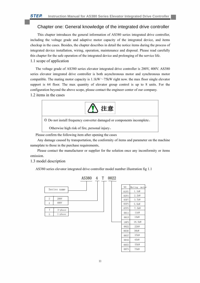
1.3 model description
AS380 series elevator integrated drive controller model number illustration fig 1.1
NO Mating motor
07P5 7.5kW
Series name
2 200V
4 400V
0011
0015
18P5
0022
11kW
15kW
18.5kW
22kW
T 3-phase
S 1-phase
01P5
03P7
05P5
1.1kW
3.7kW
5.5kW
2.2kW 02P2
AS380 4 T 0022
0030 30kW
0037
0045
0055
0075
37kW
45kW
55kW
75kW
Instruction Manual for AS380 Series Elevator Integrated Drive Controller
12
Fig 1.1 Model illustration of elevator integrated drive controller
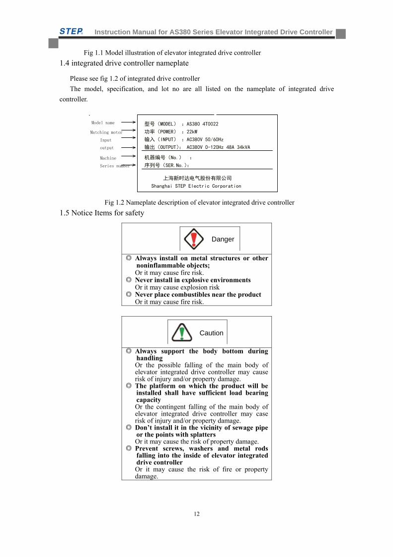
1.4 integrated drive controller nameplate
Please see fig 1.2 of integrated drive controller
The model, specification, and lot no are all listed on the nameplate of integrated drive
controller.
Fig 1.2 Nameplate description of elevator integrated drive controller
1.5 Notice Items for safety
Always install on metal structures or other
noninflammable objects; Or it may cause fire risk.
Never install in explosive environments Or it may cause explosion risk
Never place combustibles near the product Or it may cause fire risk.
Always support the body bottom during handling Or the possible falling of the main body of elevator integrated drive controller may cause risk of injury and/or property damage.
The platform on which the product will be installed shall have sufficient load bearing capacity Or the contingent falling of the main body of elevator integrated drive controller may case risk of injury and/or property damage.
Don’t install it in the vicinity of sewage pipe or the points with splatters Or it may cause the risk of property damage.
Prevent screws, washers and metal rods falling into the inside of elevator integrated drive controller Or it may cause the risk of fire or property damage.
Caution
Danger
上海新时达电气股份有限公司
Shanghai STEP Electric Corporation
型号(MODEL) :AS380 4T0022 功率(POWER) :22kW 输入(INPUT) :AC380V 50/60Hz 输出(OUTPUT): AC380V 0-120Hz 48A 34kVA
机器编号(No.) :
序列号(SER.No.):
Matching motor
Input
output
Machine
Series number
Model name
Instruction Manual for AS380 Series Elevator Integrated Drive Controller
13
Make sure it is disconnected from the mains prior to wiring Or it may cause risk of electric shock.
The wiring can only be performed by trained and qualified electricians Or it may cause risk of electric shock.
Always keep the iAStar-S8 elevated integrated drive controller properly grounded at its grounding terminal E Or it may cause risk of electric shock.
Avoid confusing main circuit input terminals and output terminals of elevator integrated drive controller Or it may cause risk of property damage and/or explosion.
Never make terminal + 1/ + 2 and - be shorted. or it may case risk of fire and explosion
Make sure the cover is placed in position prior to switching on Or it may cause risk of electric shock and/or explosion.
Don’t use soggy hands operating elevator integrated drive controller Or it may cause risk of electric shock
At completion of wiring the emergency stop safety circuit, carefully check and make sure all the wirings are correct Or it may case risk of hazard.
When switching on a elevator integrated drive controller which has been stored for more than 2 years, a voltage regulator is needed to supply it by increasing the voltage gradually Or it may cause risk of electric shock and explosion
v Avoid faulty operation when elevator
integrated drive controller is running Or it may cause risk of high-voltage electric shock.
After it is switched off, the inside of elevator integrated drive controller may remain dangerous high voltage for a certain period, don’t open the cover or touch connection terminals Or it may cause risk of high-voltage electric shock.
Danger
Danger
Danger
Instruction Manual for AS380 Series Elevator Integrated Drive Controller
14
Only trained, qualified and authorized person may be allowed to work on elevator integrated drive controller Or it may cause risk of electric shock or property damage.
Always remove watches, rings or other metal articles prior to working and always wear suitable clothes and use appropriate tools when working on elevator integrated drive controller Or it may cause risk of electric shock and explosion.
1.6 operation notice
Please notice the following points when using AS380 series integrated drive controller.
1.6.1 Brake resistor selection
Elevator feature potential energy load, four quadrants movements’ characteristic,
and the occurrence of power-generation by braking. Therefore, users should consider adding brake
component to the integrated drive controller. Otherwise, tripping may be caused with overvoltage
fault. AS380 series integrated drive controller is equipped with brake unit, so only external brake
resistor is required. The specification table 1.1 for external brake resistor of integrated drive
controller
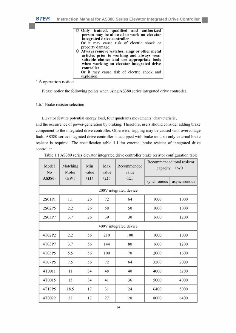
Table 1.1 AS380 series elevator integrated drive controller brake resistor configuration table
Model
No
AS380-
Matching
Motor
(kW)
Min
value
(Ω)
Max
value
(Ω)
Recommended
value
(Ω)
Recommended total resistor
capacity (W)
synchronous asynchronous
200V integrated device
2S01P1 1.1 26 72 64 1000 1000
2S02P5 2.2 26 58 50 1000 1000
2S03P7 3.7 26 39 30 1600 1200
400V integrated device
4T02P2 2.2 56 210 100 1000 1000
4T03P7 3.7 56 144 80 1600 1200
4T05P5 5.5 56 100 70 2000 1600
4T07P5 7.5 56 72 64 3200 2000
4T0011 11 34 48 40 4000 3200
4T0015 15 34 41 36 5000 4000
4T18P5 18.5 17 31 24 6400 5000
4T0022 22 17 27 20 8000 6400
Instruction Manual for AS380 Series Elevator Integrated Drive Controller
15
4T0030 30 11 20 15 10000 8000
4T0037 37 8 16 12 12000 10000
4T0045 45 5 10 9 18000 15000
4T0055 55 5 8 8 22000 18000
4T0075 75 5 6 6 30000 25000
1.6.2 Absorber at the output side prohibited
Since the output of integrated drive controller is impulse wave, installation of power
factor-improving capacitor or piezoresistor for lightning protection at output side will cause the
fault tripping or component damage of integrated drive controller.
The above issue must be taken full consideration in designing. If conducting used elevator
renovation, the capacitor or piezoresistor previously connected to the circuit output side must be
removed.
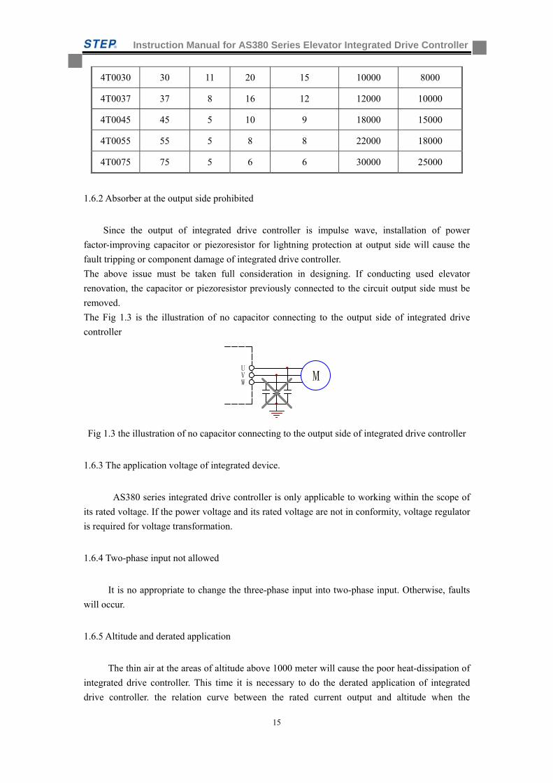
The Fig 1.3 is the illustration of no capacitor connecting to the output side of integrated drive
controller
VU
WM
Fig 1.3 the illustration of no capacitor connecting to the output side of integrated drive controller
1.6.3 The application voltage of integrated device.
AS380 series integrated drive controller is only applicable to working within the scope of
its rated voltage. If the power voltage and its rated voltage are not in conformity, voltage regulator
is required for voltage transformation.
1.6.4 Two-phase input not allowed
It is no appropriate to change the three-phase input into two-phase input. Otherwise, faults
will occur.
1.6.5 Altitude and derated application
The thin air at the areas of altitude above 1000 meter will cause the poor heat-dissipation of
integrated drive controller. This time it is necessary to do the derated application of integrated
drive controller. the relation curve between the rated current output and altitude when the
Instruction Manual for AS380 Series Elevator Integrated Drive Controller
16
integrated drive controller is in derated application is as below:
1000 2000 3000 4000(米)
100%
90%
80%
电流
Fig 1.4 the diagram about the relation between the rated output current and altitude
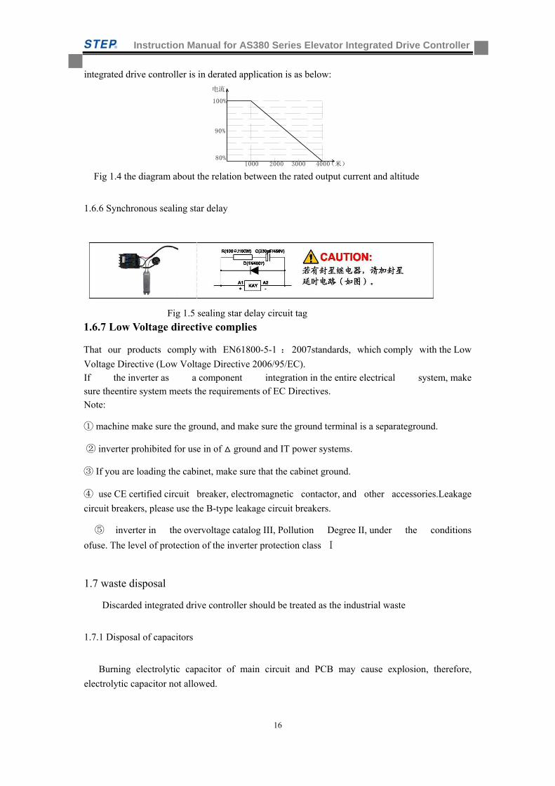
1.6.6 Synchronous sealing star delay
Fig 1.5 sealing star delay circuit tag
1.6.7 Low Voltage directive complies
That our products comply with EN61800-5-1 :2007standards, which comply with the Low
Voltage Directive (Low Voltage Directive 2006/95/EC). If the inverter as a component integration in the entire electrical system, make sure theentire system meets the requirements of EC Directives. Note:
① machine make sure the ground, and make sure the ground terminal is a separateground.
② inverter prohibited for use in of ground and IT power systems.
③ If you are loading the cabinet, make sure that the cabinet ground.
④ use CE certified circuit breaker, electromagnetic contactor, and other accessories.Leakage
circuit breakers, please use the B-type leakage circuit breakers.
⑤ inverter in the overvoltage catalog III, Pollution Degree II, under the conditions
ofuse. The level of protection of the inverter protection class Ⅰ
1.7 waste disposal
Discarded integrated drive controller should be treated as the industrial waste
1.7.1 Disposal of capacitors
Burning electrolytic capacitor of main circuit and PCB may cause explosion, therefore,
electrolytic capacitor not allowed.

Instruction Manual for AS380 Series Elevator Integrated Drive Controller
17
1.7.2 Disposal of plastic components
Several plastic components are in the integrated drive controller. Burning plastic components
may cause toxic gas, therefore, plastic components burning not allowed.\
Instruction Manual for AS380 Series Elevator Integrated Drive Controller
18
Chapter two: Model and Specification
This chapter introduces the model, specification, and installation dimension of AS380 series
integrated drive controller.
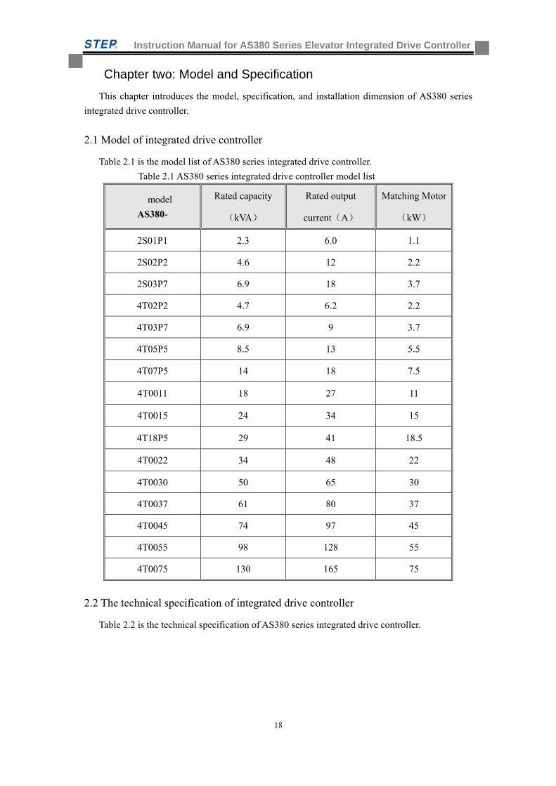
2.1 Model of integrated drive controller
Table 2.1 is the model list of AS380 series integrated drive controller.
Table 2.1 AS380 series integrated drive controller model list
model
AS380-
Rated capacity
(kVA)
Rated output
current(A)
Matching Motor
(kW)
2S01P1 2.3 6.0 1.1
2S02P2 4.6 12 2.2
2S03P7 6.9 18 3.7
4T02P2 4.7 6.2 2.2
4T03P7 6.9 9 3.7
4T05P5 8.5 13 5.5
4T07P5 14 18 7.5
4T0011 18 27 11
4T0015 24 34 15
4T18P5 29 41 18.5
4T0022 34 48 22
4T0030 50 65 30
4T0037 61 80 37
4T0045 74 97 45
4T0055 98 128 55
4T0075 130 165 75
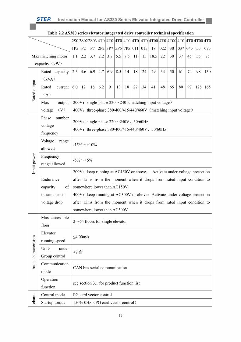
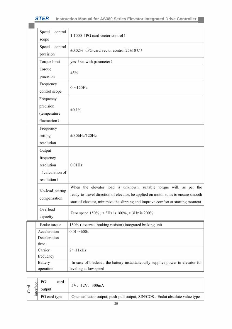
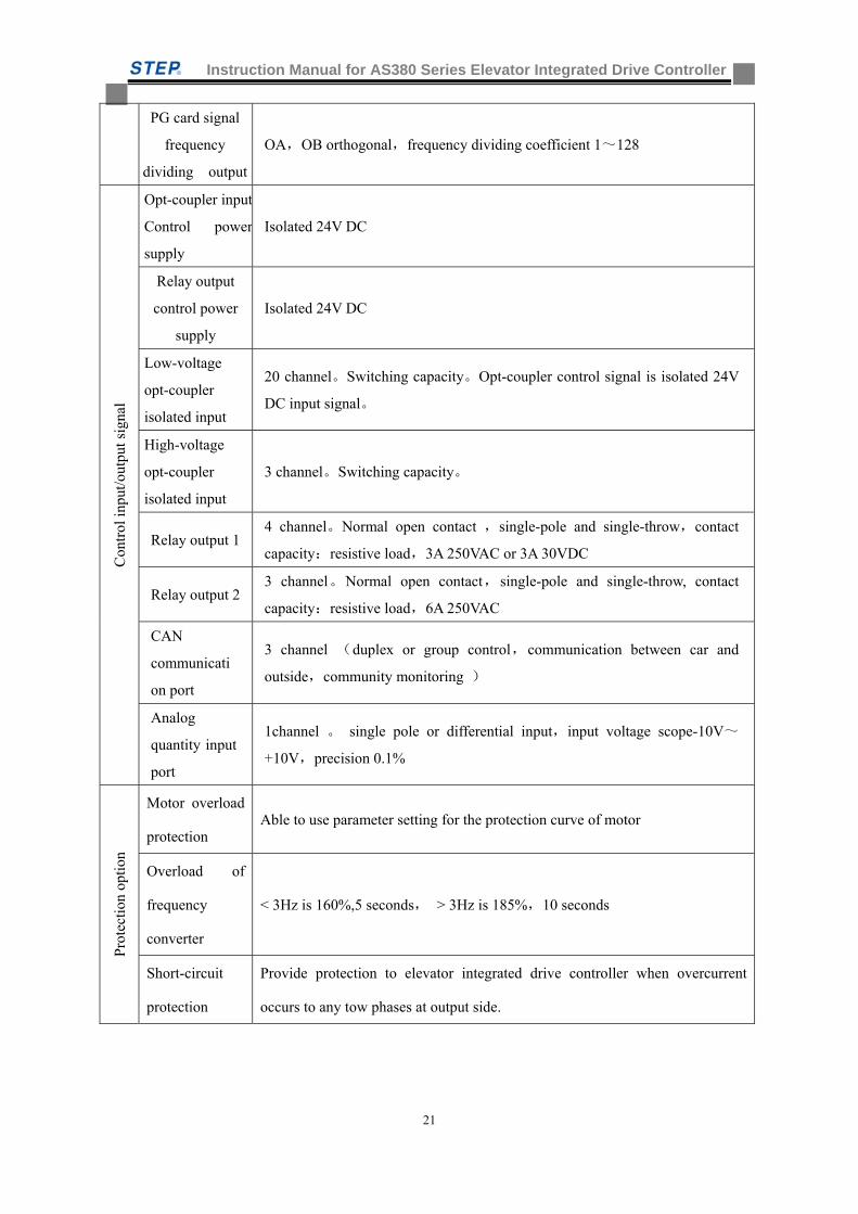
2.2 The technical specification of integrated drive controller
Table 2.2 is the technical specification of AS380 series integrated drive controller.
Instruction Manual for AS380 Series Elevator Integrated Drive Controller
19
Table 2.2 AS380 series elevator integrated drive controller technical specification
2S0
1P5
2S02
P2
2S03
P7
4T0
2P2
4T0
3P7
4T0
5P5
4T0
7P5
4T0
011
4T0
015
4T00
18
4T0
022
4T00
30
4T0
037
4T0
045
4T00
55
4T0
075
Max matching motor
capacity(kW)
1.1 2.2 3.7 2.2 3.7 5.5 7.5 11 15 18.5 22 30 37 45 55 75
Rat
ed o
utpu
t
Rated capacity
(kVA)
2.3 4.6 6.9 4.7 6.9 8.5 14 18 24 29 34 50 61 74 98 130
Rated current
(A)
6.0 12 18 6.2 9 13 18 27 34 41 48 65 80 97 128 165
Max output
voltage (V)
200V:single-phase 220~240(matching input voltage)
400V:three-phase 380/400/415/440/460V(matching input voltage)
Inpu
t pow
er
Phase number
voltage
frequency
200V:single-phase 220~240V、50/60Hz
400V:three-phase 380/400/415/440/460V、50/60Hz
Voltage range
allowed -15%~+10%
Frequency
range allowed -5%~+5%
Endurance
capacity of
instantaneous
voltage drop
200V:keep running at AC150V or above; Activate under-voltage protection
after 15ms from the moment when it drops from rated input condition to
somewhere lower than AC150V.
400V:keep running at AC300V or above;Activate under-voltage protection
after 15ms from the moment when it drops from rated input condition to
somewhere lower than AC300V.
basi
c ch
arac
teri
stic
s
Max accessible
floor 2~64 floors for single elevator
Elevator
running speed ≤4.00m/s
Units under
Group control ≤8 台
Communication
mode CAN bus serial communication
Operation
function see section 3.1 for product function list
char
a Control mode PG card vector control
Startup torque 150% 0Hz(PG card vector control)
Instruction Manual for AS380 Series Elevator Integrated Drive Controller
20
Speed control
scope 1:1000(PG card vector control)
Speed control
precision ±0.02%(PG card vector control 25±10)
Torque limit yes(set with parameter)
Torque
precision ±5%
Frequency
control scope 0~120Hz
Frequency
precision
(temperature
fluctuation)
±0.1%
Frequency
setting
resolution
±0.06Hz/120Hz
Output
frequency
resolution
(calculation of
resolution)
0.01Hz
No-load startup
compensation
When the elevator load is unknown, suitable torque will, as per the
ready-to-travel direction of elevator, be applied on motor so as to ensure smooth
start of elevator, minimize the slipping and improve comfort at starting moment
Overload
capacity Zero speed 150% , < 3Hz is 160%, > 3Hz is 200%
Car
d
inte
rfac
e PG card
output 5V、12V,300mA
PG card type Open collector output, push-pull output, SIN/COS、Endat absolute value type
Brake torque 150% ( external braking resistor),integrated braking unit
Acceleration
Deceleration
time
0.01~600s
Carrier
frequency
2~11kHz
Battery
operation
In case of blackout, the battery instantaneously supplies power to elevator for
leveling at low speed
Instruction Manual for AS380 Series Elevator Integrated Drive Controller
21
PG card signal
frequency
dividing output
OA,OB orthogonal,frequency dividing coefficient 1~128
Con
trol
inpu
t/ou
tput
sig
nal
Opt-coupler input
Control power
supply
Isolated 24V DC
Relay output
control power
supply
Isolated 24V DC
Low-voltage
opt-coupler
isolated input
20 channel。Switching capacity。Opt-coupler control signal is isolated 24V
DC input signal。
High-voltage
opt-coupler
isolated input
3 channel。Switching capacity。
Relay output 1 4 channel。Normal open contact ,single-pole and single-throw,contact
capacity:resistive load,3A 250VAC or 3A 30VDC
Relay output 2 3 channel。Normal open contact,single-pole and single-throw, contact
capacity:resistive load,6A 250VAC
CAN
communicati
on port
3 channel (duplex or group control,communication between car and
outside,community monitoring )
Analog
quantity input
port
1channel 。 single pole or differential input,input voltage scope-10V~
+10V,precision 0.1%
Pro
tect
ion
opti
on
Motor overload
protection Able to use parameter setting for the protection curve of motor
Overload of
frequency
converter
< 3Hz is 160%,5 seconds, > 3Hz is 185%,10 seconds
Short-circuit
protection
Provide protection to elevator integrated drive controller when overcurrent
occurs to any tow phases at output side.
Instruction Manual for AS380 Series Elevator Integrated Drive Controller
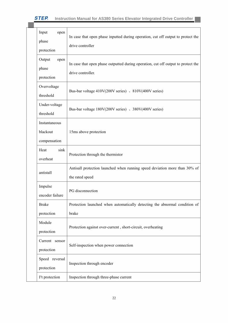
22
Input open
phase
protection
In case that open phase inputted during operation, cut off output to protect the
drive controller
Output open
phase
protection
In case that open phase outputted during operation, cut off output to protect the
drive controller.
Overvoltage
threshold Bus-bar voltage 410V(200V series) 、810V(400V series)
Under-voltage
threshold Bus-bar voltage 180V(200V series) 、380V(400V series)
Instantaneous
blackout
compensation
15ms above protection
Heat sink
overheat Protection through the thermistor
antistall Antisall protection launched when running speed deviation more than 30% of
the rated speed
Impulse
encoder failure PG disconnection
Brake
protection
Protection launched when automatically detecting the abnormal condition of
brake
Module
protection Protection against over-current , short-circuit, overheating
Current sensor
protection Self-inspection when power connection
Speed reversal
protection Inspection through encoder
I²t protection Inspection through three-phase current
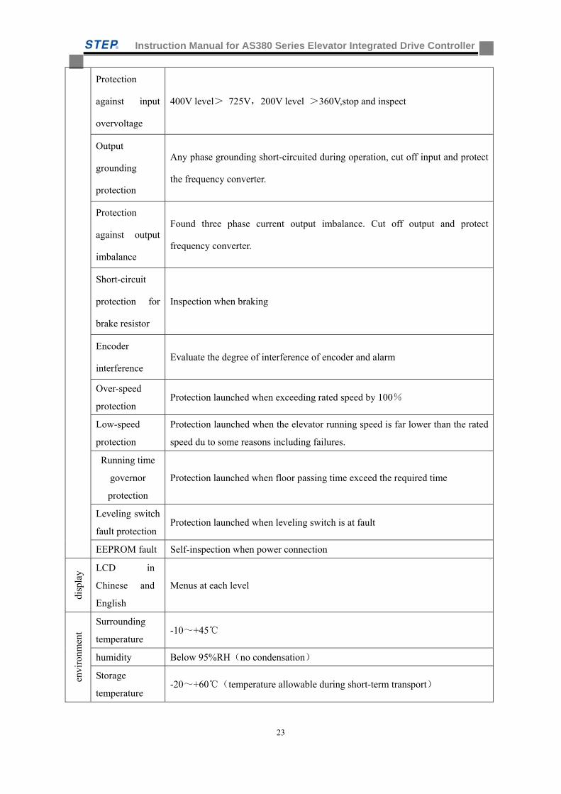
Instruction Manual for AS380 Series Elevator Integrated Drive Controller
23
Protection
against input
overvoltage
400V level> 725V,200V level >360V,stop and inspect
Output
grounding
protection
Any phase grounding short-circuited during operation, cut off input and protect
the frequency converter.
Protection
against output
imbalance
Found three phase current output imbalance. Cut off output and protect
frequency converter.
Short-circuit
protection for
brake resistor
Inspection when braking
Encoder
interference Evaluate the degree of interference of encoder and alarm
Over-speed
protection Protection launched when exceeding rated speed by 100%
Low-speed
protection
Protection launched when the elevator running speed is far lower than the rated
speed du to some reasons including failures.
Running time
governor
protection
Protection launched when floor passing time exceed the required time
Leveling switch
fault protection Protection launched when leveling switch is at fault
EEPROM fault Self-inspection when power connection
disp
lay LCD in
Chinese and
English
Menus at each level
envi
ronm
ent
Surrounding
temperature -10~+45
humidity Below 95%RH(no condensation)
Storage
temperature -20~+60(temperature allowable during short-term transport)
Instruction Manual for AS380 Series Elevator Integrated Drive Controller
24
Application
place indoor(no corrosive gas 、dust and the like)
altitude Below 1000m
stru
ctur
e
Protection
grade IP20
Cooling
mode Force air-cooling
Installation mode In-cabinet installation
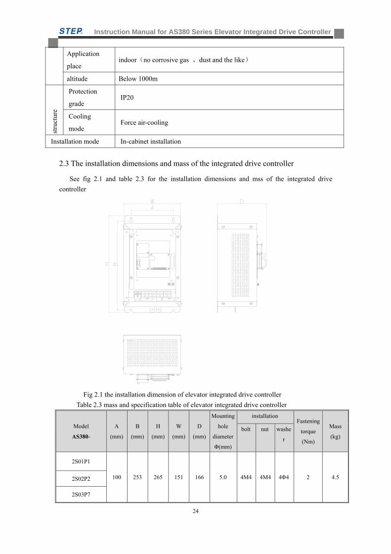
2.3 The installation dimensions and mass of the integrated drive controller
See fig 2.1 and table 2.3 for the installation dimensions and mss of the integrated drive
controller
Fig 2.1 the installation dimension of elevator integrated drive controller
Table 2.3 mass and specification table of elevator integrated drive controller
Model
AS380-
A
(mm)
B
(mm)
H
(mm)
W
(mm)
D
(mm)
Mounting
hole
diameter
Φ(mm)
installation Fastening
torque
(Nm)
Mass
(kg) bolt nut washe
r
2S01P1
100 253 265 151 166 5.0 4M4 4M4 4Φ4 2 4.5 2S02P2
2S03P7
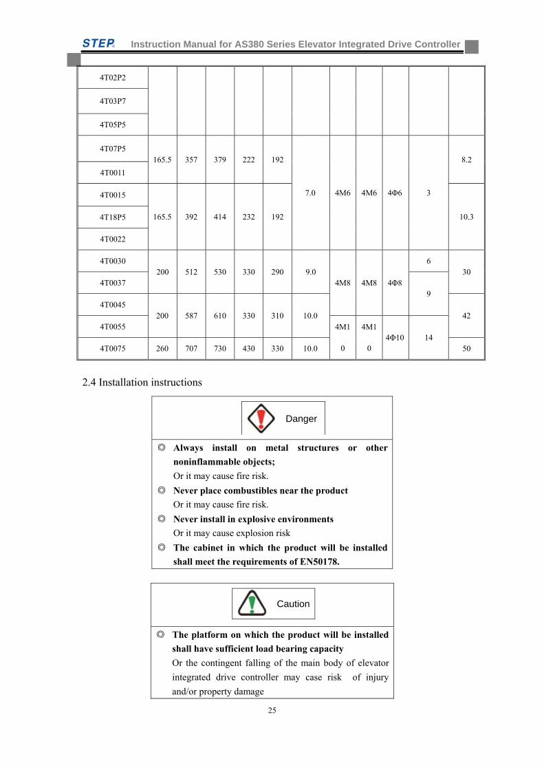
Instruction Manual for AS380 Series Elevator Integrated Drive Controller
25
4T02P2
4T03P7
4T05P5
4T07P5 165.5 357 379 222 192
7.0
4M6
4M6 4Φ6 3
8.2
4T0011
4T0015
165.5 392 414 232 192 10.3 4T18P5
4T0022
4T0030 200 512 530 330 290 9.0
4M8 4M8 4Φ8
6 30
4T0037 9
4T0045 200 587 610 330 310 10.0 42
4T0055 4M1
0
4M1
0 4Φ10 14
4T0075 260 707 730 430 330 10.0 50
2.4 Installation instructions
Always install on metal structures or other
noninflammable objects;
Or it may cause fire risk.
Never place combustibles near the product
Or it may cause fire risk.
Never install in explosive environments
Or it may cause explosion risk
The cabinet in which the product will be installed
shall meet the requirements of EN50178.
The platform on which the product will be installed
shall have sufficient load bearing capacity
Or the contingent falling of the main body of elevator
integrated drive controller may case risk of injury
and/or property damage
Caution
Danger
Instruction Manual for AS380 Series Elevator Integrated Drive Controller
26
Don’t install it in the vicinity of sewage pipe or the
points with splatters
Or it may cause risk of property damage.
Prevent screws, washers and metal rods falling into
the inside of elevator integrated drive controller
Or it may cause the risk of fire or property damage.
Never start a elevator integrated drive controller
which is damaged or components are not completed
mounted
Or it may cause risk of property damage.
Don’t install under direct sunlight
Or it may cause risk of overheat or resulting accidents;
2.4.1 Product installation location
The place where the elevator integrated drive controller will be installed shall meet such
conditions as:
a) Clean, without oil mist, dust or suspended matters which may fly into the fully enclosed
cabinet;
b) No possibility of metal powder, oil or water entering into the inside of elevator integrated
drive controller;
c) No timers and other combustibles are stored;
d) No radioactive substances are placed;
e) No hazardous gases or liquids are stored;
f) Vibration is as low as possible;
g) Not a salty atmosphere;
h) Not under direct sunlight;
i) Temperature rise is as low as possible;
when install the product in a enclosed cabinet, suitable cooling fans or air conditioners should be
provided to keep the ambient temperature under 40。
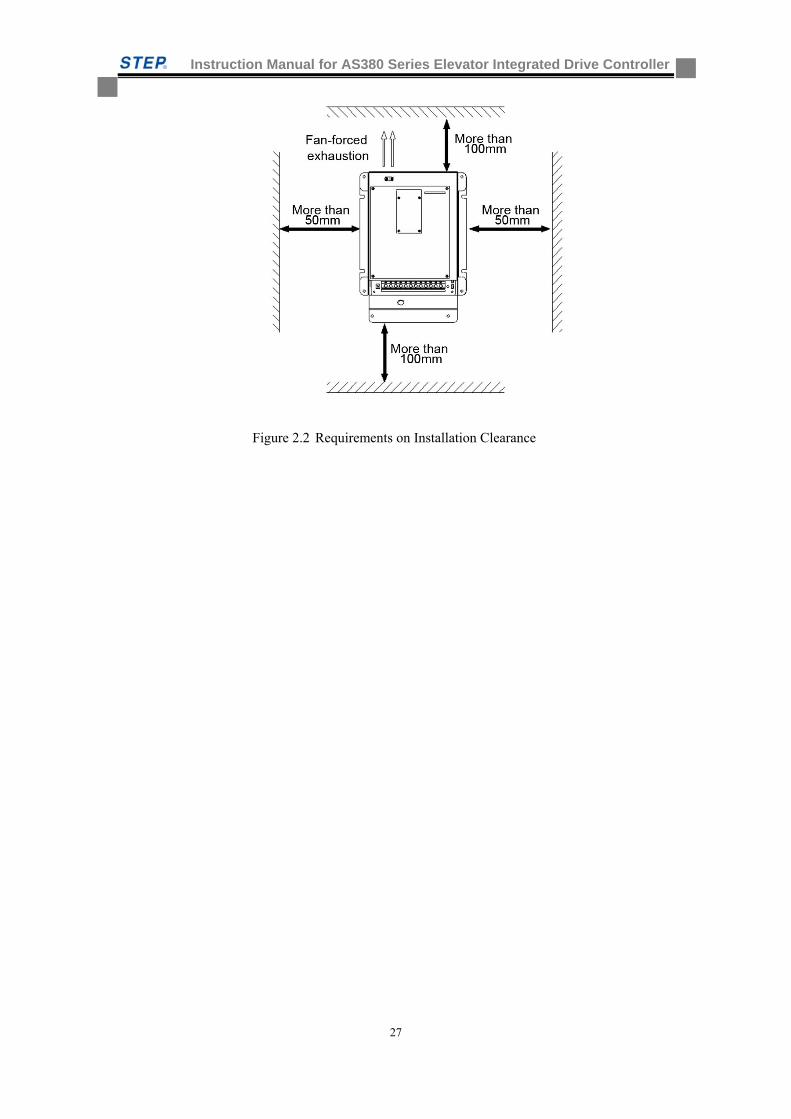
2.4.2 Product installation positioning and clearance requirements
To avoid impair the cooling effect of elevator integrated drive controller; this product shall be
installed at a well-ventilated place. In general, it is vertically installed with suitable clearances as
shown by Figure 2.2
Instruction Manual for AS380 Series Elevator Integrated Drive Controller
27
Figure 2.2 Requirements on Installation Clearance
Instruction Manual for AS380 Series Elevator Integrated Drive Controller
28
Chapter Three: product function
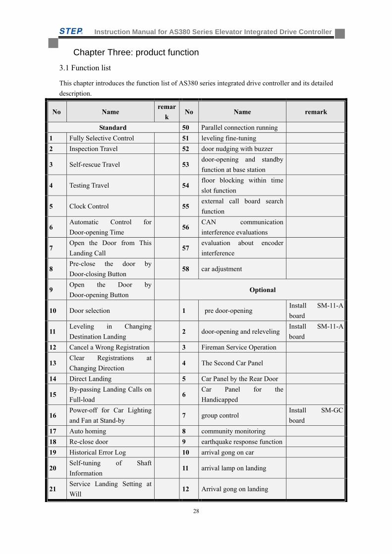
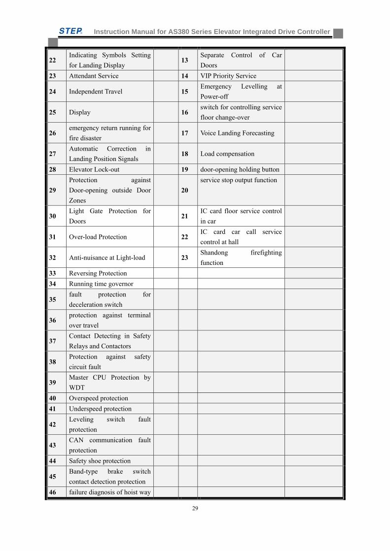
3.1 Function list
This chapter introduces the function list of AS380 series integrated drive controller and its detailed
description.
No Name remar
k No Name remark
Standard 50 Parallel connection running
1 Fully Selective Control 51 leveling fine-tuning
2 Inspection Travel 52 door nudging with buzzer
3 Self-rescue Travel 53 door-opening and standby
function at base station
4 Testing Travel 54 floor blocking within time
slot function
5 Clock Control 55 external call board search
function
6 Automatic Control for
Door-opening Time 56
CAN communication
interference evaluations
7 Open the Door from This
Landing Call 57
evaluation about encoder
interference
8 Pre-close the door by
Door-closing Button 58 car adjustment
9 Open the Door by
Door-opening Button Optional
10 Door selection 1 pre door-opening Install SM-11-A
board
11 Leveling in Changing
Destination Landing 2 door-opening and releveling
Install SM-11-A
board
12 Cancel a Wrong Registration 3 Fireman Service Operation
13 Clear Registrations at
Changing Direction 4 The Second Car Panel
14 Direct Landing 5 Car Panel by the Rear Door
15 By-passing Landing Calls on
Full-load 6
Car Panel for the
Handicapped
16 Power-off for Car Lighting
and Fan at Stand-by 7 group control
Install SM-GC
board
17 Auto homing 8 community monitoring
18 Re-close door 9 earthquake response function
19 Historical Error Log 10 arrival gong on car
20 Self-tuning of Shaft
Information 11 arrival lamp on landing
21 Service Landing Setting at
Will 12 Arrival gong on landing
Instruction Manual for AS380 Series Elevator Integrated Drive Controller
29
22 Indicating Symbols Setting
for Landing Display 13
Separate Control of Car
Doors
23 Attendant Service 14 VIP Priority Service
24 Independent Travel 15 Emergency Levelling at
Power-off
25 Display 16 switch for controlling service
floor change-over
26 emergency return running for
fire disaster 17 Voice Landing Forecasting
27 Automatic Correction in
Landing Position Signals 18 Load compensation
28 Elevator Lock-out 19 door-opening holding button
29
Protection against
Door-opening outside Door
Zones
20
service stop output function
30 Light Gate Protection for
Doors 21
IC card floor service control
in car
31 Over-load Protection 22 IC card car call service
control at hall
32 Anti-nuisance at Light-load 23 Shandong firefighting
function
33 Reversing Protection
34 Running time governor
35 fault protection for
deceleration switch
36 protection against terminal
over travel
37 Contact Detecting in Safety
Relays and Contactors
38 Protection against safety
circuit fault
39 Master CPU Protection by
WDT
40 Overspeed protection
41 Underspeed protection
42 Leveling switch fault
protection
43 CAN communication fault
protection
44 Safety shoe protection
45 Band-type brake switch
contact detection protection
46 failure diagnosis of hoist way
Instruction Manual for AS380 Series Elevator Integrated Drive Controller
30
self-study
47 motor thermal protection
48 Door lock fault protection
49 Door lock disconnection
protection
3.2 elevator operation function description and setting method
3.2.1 Standard function description
1. Fully Selective Control
When in automatic or attendant control, the elevator stops in response to the in-car registrations
while automatically follows landing calls up and down, i.e., a passenger can register his or her call
at any landing.
2.Inspection Travel
It is a function for field mechanics or engineers to carry out maintenance, inspection or testing
tasks. When operational conditions are satisfied, an authorized person can inch the car by pressing
and releasing the red button, he can move the car at inspection speed by continuously pushing
down the button and stop it by releasing the button.
3.Self-rescue Travel
When the elevator stays out of the leveling zone (NOT in inspection state), it will automatically
move to the leveling zone slowly to evacuate the passengers only if the safety requirements for the
start are met.
4.Testing Travel
It is a function designed for measuring the performance of a new elevator. By setting a given
parameter in testing travel on the Master Control board, a field engineer will put the elevator into
automatic operation. Both the total number of trips and the interval time between trips of the
testing travel can be determined by parameter setting.
5. Clock Control
With the built-in clock system by real time, the exact time at which a breakdown takes place can
be recorded in the Error Log. Besides, some clock control- related functions all use the clock time
as the standard one
6. Automatic Control for Door-opening Time
when the elevator travels in automatic state without attendant, the door closes automatically by a
delay after the car arrives at a landing with the door open.
7.Open the Door from This Landing
when the call button of this landing is pressed down, the car door opens automatically. If someone
keeps pushing on the button, the door remains open.
Instruction Manual for AS380 Series Elevator Integrated Drive Controller
31
8.Pre-close the Door by Door-closing Button
when the door is open in automatic state, the door can be closed immediately before the delay
elapses by pushing on the door-closing button.
9.Open the door by Door-opening Button
when the car stays within the door zone, a passenger in the car can open a closed door or make a
closing door reverse by pushing on the door-opening button.
10.Door Selection
you may set parameter to select different door machine, which includes such types as
opening-torque hold, closing-torque hold and opening/closing-torque holding.
11.Leveling on Changing Destination landing
if the door has been opening longer than the setting time without activating the door open limit
switch, the door will close and the elevator will travel to the next floor after the door is closed.
12 Cancel a Wrong Registration
if a passenger realizes that he or she has pushed down a wrong button in the car panel, he or she
can cancel the wrong registration by pushing the same button twice incessantly.
The registered signal will be canceled. This function can be activated by the parameter setting.
13.Clear Registrations at Changing Direction
when the elevator car arrives at the last landing and is about to reverse the direction, all the
registrations behind its present travel will be cancelled at once.
14.Direct landing
the control system decelerates the elevator according to distance principle. No creeping when
leveling.
15 full load by pass
When a full-loaded elevator car travels in automatic mode without attendant, the elevator will
NOT answer any calls from its passing landings, stopping at the landings by in-car registrations
only.
16 Power-off for Car Lighting and Fan at Stand-by
If a elevator in automatic mode stands by out of service over 3 minutes (default value of 3
minutes subject to change by parameter), receiving neither in-car nor landing calls, the car lighting
and fan will automatically stays off power until a call for the elevator to answer appears.
17. Auto Homing
When the elevator travels in automatic mode without attendant service while setting Auto Homing
in effect, the elevators which receives neither in-car nor landing calls will automatically return to
the main landing within a given period of time determined by parameter setting.
18.Re-close door
In order to prevent door-closing failure from the contingent failure of the door machine system
and possible door block by something, this function is therefore provided to re-close the door.
19.Fault history Log
The Fault history Log keeps the latest 20 fault records concerning the occurrence time, floors and
fault codes.
Instruction Manual for AS380 Series Elevator Integrated Drive Controller
32
20 hoist way landing data self-study
the hoist way self-study system should be activated before the elevator goes into service. The
system will study various kinds of data within the hoist way and save those running data
permanently.
21 Service Landing arbitrarily Setting
Using the handheld operator to set at will which floors the elevator serves and which floors the
elevator does NOT serve.
22 Indicating Symbols Setting for Landing Display
Using the handheld operator to set at will the varied display symbols or marks for each floors, for
instance, “B” for underground ONE.
23 Attendant Service
using the switch in the car operation panel, one can put the elevator into attendant service, under
which the automatic door closing is absent and the door can only be closed when attendant keep
pressing the door-closing button. Meanwhile the function can also allow attendant to choose
direction and by-passing.
24 Independent Travel
Independent Travel is an exclusive travel, during which the elevator overlooks all landing calls
and the automatic door-closing is absent. Other features are similar to Attendant Service.
25 Dot-matrix Landing Indicators
Dot-matrix Landing Indicators are used both in the car and on the landing, displaying such
information as the floor position, running direction, elevator status and etc
26 emergency elevator returning against fire
When encountering fire, passenger set the fire returning switch in position. Elevator
immediately cancels all the instruction and call and travel to firefighting station for door-opening
and stand-by.
27 Automatic Correction in Landing Position Signals
the traveling elevator system compare its own position signals at each terminal switch and the
leveling switch of each landing against those obtained by self-study and making automatic data
corrections accordingly.
28 Elevator Lock-in
setting the lock-in switches of elevator in automatic mode or with attendant, and clear up all the
registration call. The elevator only respond to the in-car instruction until no new instructions
registered. Then the elevator returns to the base station, turns off in-car lighting and fan after
opening the door automatically, lighten the door-opening button indicator, and automatically close
the door when 10 seconds time delay expired. Finally, the elevator stops running, and will be back
to operation when the lock-in switch reset.
29 Protection against Door-opening outside Door Zones
The door cannot open outside the door zone, which is preset by the system for safety concern.
30 Light Gate Protection for Doors
every elevator is equipped with a light gate door protection, whenever any object appears or stays
Instruction Manual for AS380 Series Elevator Integrated Drive Controller
33
between the closing doors, the light gate protection or safety contact plate will be activated to
reopen the doors. The light gate protection is not in effect when elevator is in fire-fighting mode.
31 Over-load Protection
With the over-load switch functioning, the door remains open with alarm buzzing on
32 Anti-nuisance at Light-load
when the elevator is in light-load mode, the in-car registrations have reached or exceeded the
setting value. The system will clear all the registrations.
33 Reversing Protection
when the system has detected an inconsistency between the elevator registered direction and travel
direction for a while, an emergency stop will be activated with alarm buzzing on.
34 Operation Time Limiter
If the elevator in operation has traveled incessantly for a longer time than the value preset by the
time limiter (max.45s) without leveling, all elevator operation will be stopped.
35 Deceleration switch failure protection
When encountering the deceleration switch failure, elevator land in emergency to avoid possible
top or bottom floor collision
36.Protection against terminal overtravels
both the uppermost and the lowest ends of the hoistway are mounted with limit switches and speed
retardation switch to prevent any elevator over-travels
37 Contact Detection protection of Safety Relay and Contactor
The system checks up the contact reliability of the safety relays and contactors. If any
inconformity between the contact movement and the working status of the coil is detected, all car
movements will be stopped.
38.Main Circuit Fault protection:
Emergency stop occurs once system receives the signals indicating failure of main circuit. This
function is also able to prevent running of a elevator at fault.
39 Master CPU Protection by WDT
The master control PCB is integrated with WDT protection. When any CPU or program problems
are detected, the WDT Circuit will make a forced cutoff at the output terminals of the Master
Control and reset the CPU.
40 Overspeed Protection:
This protection function is provided to avoid safety problems due to elevator running speed higher
than control limit.
41 Underspeed Protection:
This protection function is provided to avoid safety problems due to elevator running speed lower
than control limit.
42 Leveling Switch Fault Protection:
A protection functions to be activated in case of abnormal situations caused by failure of leveling
switch.
Instruction Manual for AS380 Series Elevator Integrated Drive Controller
34
43. CAN Communication Fault Protection:
It prevents possible danger in case of CAN communication failure and elevator keep running.
44. Safety contact pad Protection:
When the door is about to close and door safety contact pad is activated, the elevator will
automatically open the door or keep the door opening for the prevention of possible clamping
passengers.
45. Band-type Brake Switch Contact Detection Protection:
the system check the reliability of band-type brake through its switch. Protection will be launched
once the band-type brake is found not reliable.
46. Elevator hoist way self-study failure diagnosis:
Because the hoist way data is the basis for the control system running in quick car mode. Elevator
can not run properly without the correct hoist way data. Therefore, the hoist way self-study failure
diagnosis is set for hoist way self-study failure.
47. Motor Thermal Protection:
the protection aims to prevent the possible danger caused by motor overheating.
48. Door Switch Fault Protection:
The protection shall be activated to stop elevator once system detect abnormal condition of door
lock.
49. Door Lock disconnection Protection:
Elevator will stop once lock disconnection is found in operation.
50 Parallel connection running
the coordination of landing calls between two elevators is realized through CAN serial
communication bus-based data transfer between the two elevators. The running efficiency of the
elevators is improved.
51 leveling fin-tuning
Use the software to adjust the leveling switch position of each floor within a tiny range. So the
complicated procedure of adjusting leveling plug-in board can be avoided.
52 door nudging
Activate the door nudging function. If the elevator keep door opening and no door-closing signal
are sent due to light curtain or other reason, the elevator will be closed and acoustic warning will
alarmed.
53 base station doo-opening standby function
use parameter setting to choose the elevator door-opening and standby when it is in base station.
54 floor blocking within time slot fun
Conduct the specific blocking service to designated floor at specific time. The specific block
service means that user can choose to block outside call registration independently, blocking
Instruction Manual for AS380 Series Elevator Integrated Drive Controller
35
instruction registration independently, blocking instruction and outside instruction registration.
Meanwhile, user can also choose not to block.
55 External board search function
Use operator to check whether the external board at each floor work properly or not.
56 evaluations on CAN communication interference
Use the operator to check the communication quality of CAN
57 Evaluation on encoder interference
Use operator to check the interference of encoder signal.
58 car adjustment
Revolutionary elevator adjustment method is provided. Working staffs can adjust the elevator
directly inside the car, monitor the elevator running condition so as to make the adjustment of
elevator leveling, comfort and other function more user-friendly.
3.2.2 Optional function description
1. door pre-opening
The option enable leveling elevator to open door immediately upon arrival at the pre door-opening
zone. In this way the elevator operation is more efficient
2. door-opening and releveling
Due to the stretch of wire ropes in case of high-rise buildings, the parking car may move up and
down while passengers leave and board the car, which may lead to mal-levelling. Once this
situation is detected by the system, the control will make the car relevel at a slow speed with the
door open.
3.Fireman Service
The fireman switch is set on in case of fire, the elevator will immediately clear out all instruction
& call and return to firefighting base station. Then system switches to fireman service mode.
4 The auxiliary car operating Panel
The auxiliary car operating panel is available for installation when the main car operating panel is
installed. Passengers can use it to register instruction and operate the doors.
5 operating panel for the rear door
Rear door operating panel is recommended when elevator has both front and rear door. Passenger
can use the rear door operating panel to register instruction and operate the doors.
6 operating panel for the disable
Operating panel for the disabled is available for the disabled to operate the elevators.
7 group control operation
Use group control controller to coordinate landing calls of elevators in the bank. In this way the
running efficiency of elevator can be improved. And function such as peak service and distribution
waiting state are provided. The group control system can control up to 8 units
8 communities (building) monitoring
Control system link to the PCs in monitoring room through CAN communication line. Working
Instruction Manual for AS380 Series Elevator Integrated Drive Controller
36
staff can monitor the elevator position, running direction and fault condition and etc.
9 earthquake response function
Activate the earthquake function. if earthquake occur, the earthquake inspection device activated.
A contact signal from the device will be transferred to the control system. The control system will
instruct the running elevator to park at nearest floor and open the doors for passenger evacuation
as well as stop the elevator then.
10 car arrival gong
The Up/Down arrival gong installed at the top, bottom of the car will ring as the elevator
decelerate and level, alarming the passenger in car and hall that the elevator is leveling and about
to arrive.
11 arrival lamp at landing
Activate the function. The up/down arrival lamp installed at the hall of each floor will inform
passengers the upcoming arrival of the elevator.
12 arrival gong at landing
Activate the function. The up/down arrival gong at hall of each floor will inform passengers the
upcoming arrival of the elevator.
13 independent control of front and rear door
Passenger can make independent control of the front and rear door according to their own needs.
14 VIP priority service
A special service for the VIP passengers, the function enables the VIP passenger to arrival the
destination floor at fastest speed.
15 Emergency leveling when blackout
The building blackout causes the running elevator fail to reach the door zone and entrapment
occurs as the consequence. Under the above circumstance does the blackout emergency leveling
device activated. The elevator will be pushed at the low speed to the nearest door zone for
passenger evacuation.
16 service floor change-over by the switch control
Use the in-car switch to change the elevator service floor.
17 broadcasting function for upcoming floor
When install the floor broadcasting function to the system, the floor broadcaster will report the
upcoming floor during the leveling process and report the subsequent running direction of the
elevator at each time of door-closing.
18 weighing compensation
The load compensation value is given based on the car load data inspected by the weighing device.
In this way the elevator startup comfort will be improved.
19 door-opening holding buttons
Use the door holding button to enable the door-closing delay
20 out of service display
A display method to inform passenger that elevator is out of service.
21 IC card floor service control in car
Once this function is installed, a card reader is installed in the operating panel. Passenger must use
the card to register the instruction for authorized floors
22 IC card elevator call service control at hall
Once this function is installed, a card reader is installed at the call panel of each floor. Passenger

Instruction Manual for AS380 Series Elevator Integrated Drive Controller
37
must use the card to register the call signal for the corresponding floor.
23 Shangdong firefighting function,can be set by F35: 1)1)After open the in place at the fire base
station in fire return state,output fire instructions.2)In fireman state and elevator at base
station . output fire instructions,when elevator leave the fire base station, not output fire
instructions。
Instruction Manual for AS380 Series Elevator Integrated Drive Controller
38
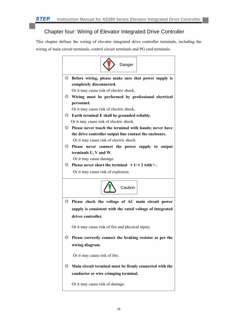
Chapter four: Wiring of Elevator Integrated Drive Controller
This chapter defines the wiring of elevator integrated drive controller terminals, including the
wiring of main circuit terminals, control circuit terminals and PG card terminals.
Danger
Before wiring, please make sure that power supply is
completely disconnected.
Or it may cause risk of electric shock.
Wiring must be performed by professional electrical
personnel.
Or it may cause risk of electric shock.
Earth terminal E shall be grounded reliably.
Or it may cause risk of electric shock.
Please never touch the terminal with hands; never have
the drive controller output line contact the enclosure.
Or it may cause risk of electric shock.
Please never connect the power supply to output
terminals U, V and W.
Or it may cause damage.
Please never short the terminal +1/ +2 with -.
Or it may cause risk of explosion.
Please check the voltage of AC main circuit power
supply is consistent with the rated voltage of integrated
driver controller.
Or it may cause risk of fire and physical injury.
Please correctly connect the braking resistor as per the
wiring diagram.
Or it may cause risk of fire.
Main circuit terminal must be firmly connected with the
conductor or wire crimping terminal.
Or it may cause risk of damage.
Caution
Instruction Manual for AS380 Series Elevator Integrated Drive Controller
39
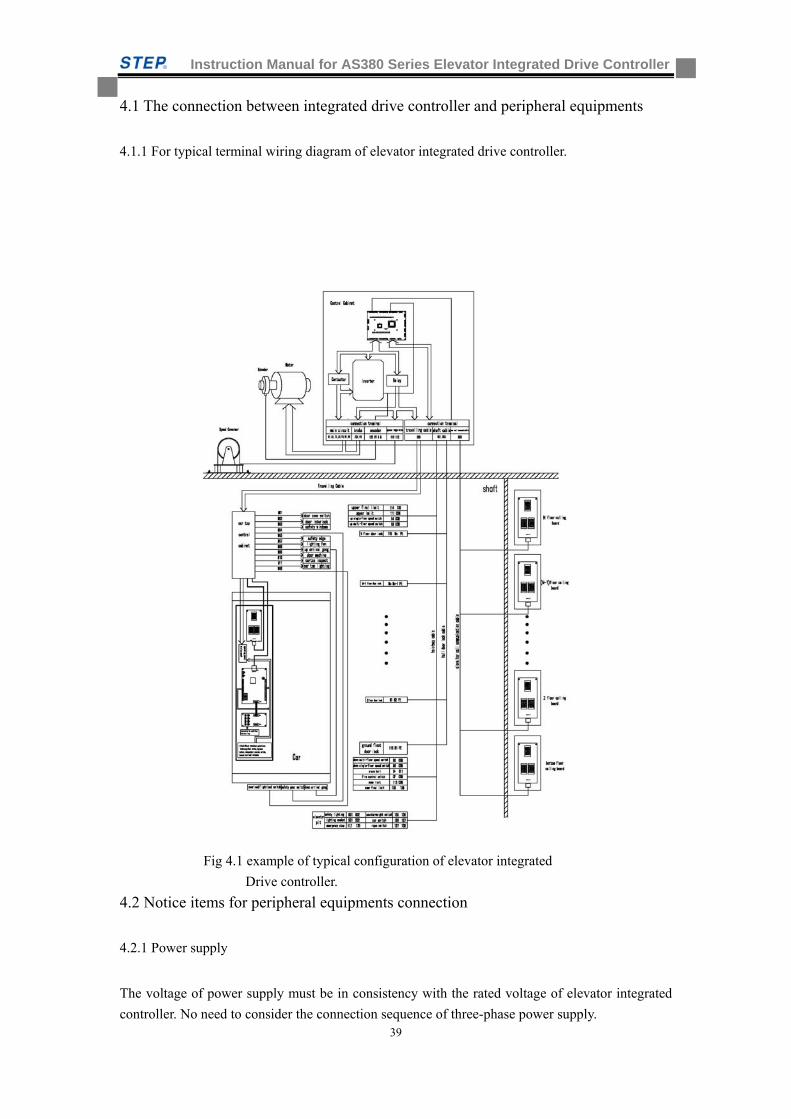
4.1 The connection between integrated drive controller and peripheral equipments
4.1.1 For typical terminal wiring diagram of elevator integrated drive controller.
Fig 4.1 example of typical configuration of elevator integrated
Drive controller.
4.2 Notice items for peripheral equipments connection
4.2.1 Power supply
The voltage of power supply must be in consistency with the rated voltage of elevator integrated
controller. No need to consider the connection sequence of three-phase power supply.
Instruction Manual for AS380 Series Elevator Integrated Drive Controller
40
4.2.2 Breaker
The breaker must be used between the power supply and input terminal of elevator integrated
drive controller. the capacity of breaker should be 1.5~2 times of the rated current of AS 380
series elevator integrated drive controller. The time behavior of overheating protection of elevator
integrated drive controller should be taken into full consideration for that of the breaker.
4.2.3 AC reactor at the input side
AC reactor at the input side can be used as option to improve the power factor of input power
supply and reduce ultra-harmonics current.
4.2.4 Interference filter at the input side
Specialized interference filter at the input side can be used as option to restrain power supply from
high frequency noise interference of elevator integrated drive controller.
4.2.5 Main circuit output contactor
This contactor is used for controlling the current flow of tractor. The contractor engages every
time before the elevator start up and release when the elevator stops. It is must-have safety device
installed between the drive device and tractor motor.
4.2.6 Interference filters at the output side.
Specialized interference filter at the input side can be used to restrain the power supply from high
frequency noise interference of elevator integrated drive controller.
4.2.7 AC reactor at output side
The AC reactor at the output side is used as option to restrain the radio-frequency interference of
elevator integrated drive controller.
When the wiring length between elevator integrated drive controller and motor is too long
(>20m), the AC reactor at output side can prevent the overflow of elevator integrated controller
caused by wire distributed capacitance.
4.2.8 DC reactor
DC reactor can be used as option for the improvement of power factor.
Instruction Manual for AS380 Series Elevator Integrated Drive Controller
41
4.3 The technical requirements for wire arrangement of peripheral equipments of the elevator integrated drive controller.
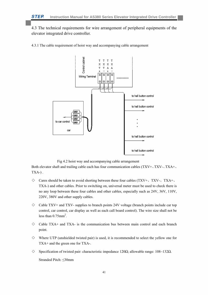
4.3.1 The cable requirement of hoist way and accompanying cable arrangement
Fig 4.2 hoist way and accompanying cable arrangement
Both elevator shaft and trailing cable each has four communication cables (TXV+、TXV-、TXA+、
TXA-) .
Cares should be taken to avoid shorting between these four cables (TXV+、TXV-、TXA+、
TXA-) and other cables. Prior to switching on, universal meter must be used to check there is
no any loop between these four cables and other cables, especially such as 24V, 36V, 110V,
220V, 380V and other supply cables.
Cable TXV+ and TXV- supplies to branch points 24V voltage (branch points include car top
control, car control, car display as well as each call board control). The wire size shall not be
less than 0.75mm2.
Cable TXA+ and TXA- is the communication bus between main control and each branch
point.
Where UTP (unshielded twisted pair) is used, it is recommended to select the yellow one for
TXA+ and the green one for TXA-.
Specification of twisted pair: characteristic impedance 120Ω; allowable range: 108~132Ω.
Stranded Pitch: ≤30mm
Instruction Manual for AS380 Series Elevator Integrated Drive Controller
42
Wire size: ≥0.75mm2
Communication line and power line must be wired respectively
Grounding of Elevator Shaft Cable and Trailing Cable
During wiring of shaft cable and trailing cable, please note to appropriately divide the strong
current line (includes door machine power supply, safety circuit, door lock circuit and illumination
circuit, etc.) and weak current line (includes communication cable, DC 0V, DC 24V, leveling dry
reed , terminal forced slowdown switch and terminal limit switch, etc.). The communication line
must be twisted pair with strand pitch between 20 and 30 mm. it is strongly recommended to use
shielded twisted pair with grounding protection.
Note: if strong current lines and weak current lines are arranged in parallel, mostly common in
trailing cables, the strong current lines shall be arranged on one side and the weak current line on
the other side. In addition, the strong current lines and weak current lines must be separated with
grounding line.
Note: The wiring rules mentioned above must be shown on design drawings, where the specific
purpose of each wire size must also be defined.
Note: whether it is shielded or not, twisted pair must be used.
4.3.2 Method of Wiring Between Call board and TXV+、TXV-、TXA+、TXA-
Branch Bus
Branches and bus shall be soundly wired in order to avoid excess voltage drop.
It is recommended to use the wiring methods shown by the following Figure 4.3:
Figure 4.3 Wiring between Branch and Bus
The Relation between TXV+、TXV-、TXA+、TXA- and Trailing Cable
TXV+、TXV-、TXA+、TXA- and other weak current signal cables (voltage not more than
24V) are allowed to share a same trailing cable. Other strong current signal cables (voltage
higher than 24V) shall be arranged at the other trailing cable.
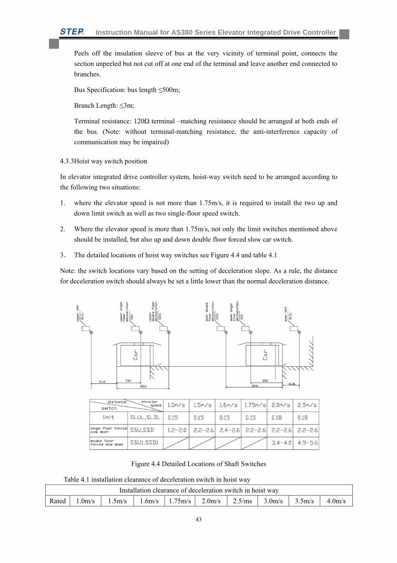
Instruction Manual for AS380 Series Elevator Integrated Drive Controller
43
Peels off the insulation sleeve of bus at the very vicinity of terminal point, connects the
section unpeeled but not cut off at one end of the terminal and leave another end connected to
branches.
Bus Specification: bus length ≤500m;
Branch Length: ≤3m;
Terminal resistance: 120Ω terminal –matching resistance should be arranged at both ends of
the bus. (Note: without terminal-matching resistance, the anti-interference capacity of
communication may be impaired)
4.3.3Hoist way switch position
In elevator integrated drive controller system, hoist-way switch need to be arranged according to
the following two situations:
1. where the elevator speed is not more than 1.75m/s, it is required to install the two up and
down limit switch as well as two single-floor speed switch.
2. Where the elevator speed is more than 1.75m/s, not only the limit switches mentioned above
should be installed, but also up and down double floor forced slow car switch.
3. The detailed locations of hoist way switches see Figure 4.4 and table 4.1
Note: the switch locations vary based on the setting of deceleration slope. As a rule, the distance
for deceleration switch should always be set a little lower than the normal deceleration distance.
Figure 4.4 Detailed Locations of Shaft Switches
Table 4.1 installation clearance of deceleration switch in hoist way
Installation clearance of deceleration switch in hoist way
Rated 1.0m/s 1.5m/s 1.6m/s 1.75m/s 2.0m/s 2.5/ms 3.0m/s 3.5m/s 4.0m/s
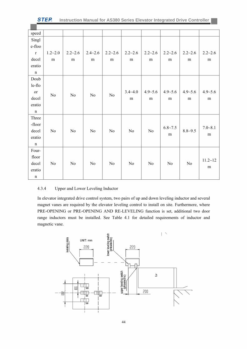
Instruction Manual for AS380 Series Elevator Integrated Drive Controller
44
speed
Singl
e-floo
r
decel
eratio
n
1.2~2.0
m
2.2~2.6
m
2.4~2.6
m
2.2~2.6
m
2.2~2.6
m
2.2~2.6
m
2.2~2.6
m
2.2~2.6
m
2.2~2.6
m
Doub
le-flo
or
decel
eratio
n
No No No No 3.4~4.0
m
4.9~5.6
m
4.9~5.6
m
4.9~5.6
m
4.9~5.6
m
Three
-floor
decel
eratio
n
No No No No No No 6.8~7.5
m 8.8~9.5
7.0~8.1
m
Four-
floor
decel
eratio
n
No No No No No No No No 11.2~12
m
4.3.4 Upper and Lower Leveling Inductor
In elevator integrated drive control system, two pairs of up and down leveling inductor and several
magnet vanes are required by the elevator leveling control to install on site. Furthermore, where
PRE-OPENING or PRE-OPENING AND RE-LEVELING function is set, additional two door
range inductors must be installed. See Table 4.1 for detailed requirements of inductor and
magnetic vane.
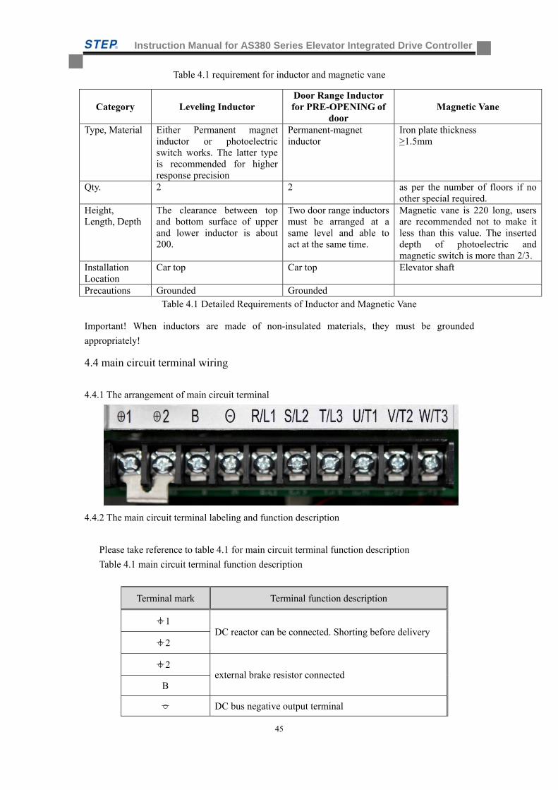
Instruction Manual for AS380 Series Elevator Integrated Drive Controller
45
Table 4.1 requirement for inductor and magnetic vane
Category Leveling Inductor Door Range Inductor for PRE-OPENING of
door Magnetic Vane
Type, Material Either Permanent magnet inductor or photoelectric switch works. The latter type is recommended for higher response precision
Permanent-magnet inductor
Iron plate thickness ≥1.5mm
Qty. 2 2 as per the number of floors if no other special required.
Height, Length, Depth
The clearance between top and bottom surface of upper and lower inductor is about 200.
Two door range inductors must be arranged at a same level and able to act at the same time.
Magnetic vane is 220 long, users are recommended not to make it less than this value. The inserted depth of photoelectric and magnetic switch is more than 2/3.
Installation Location
Car top Car top Elevator shaft
Precautions Grounded Grounded Table 4.1 Detailed Requirements of Inductor and Magnetic Vane
Important! When inductors are made of non-insulated materials, they must be grounded
appropriately!
4.4 main circuit terminal wiring
4.4.1 The arrangement of main circuit terminal
4.4.2 The main circuit terminal labeling and function description
Please take reference to table 4.1 for main circuit terminal function description
Table 4.1 main circuit terminal function description
Terminal mark Terminal function description
+1 DC reactor can be connected. Shorting before delivery
+2
+2 external brake resistor connected
B
- DC bus negative output terminal
Instruction Manual for AS380 Series Elevator Integrated Drive Controller
46
R/L1 Main circuit AC power input, three-phase input power
supply connected. S/L2
T/L3
U/T1 Integrated drive controller output, three phase
synchronous/asynchronous motor connected. V/T2
W/T3
4.4.3 Main circuit wire specification
The conductor is 600V copper-core plastic insulation conductor for power supply. See Table 4.2
for conductor specification and fastening torque.
Table 4.2 conductor specification and fastening torque
Model AS380- Connectable wire
specification(mm2)
Recommended wire
specification(mm2)
Fastening
torque(N.m)
2S01P1 2~6 2.5 1.5
2S02P2 2~6 4 1.5
2S03P7 2~6 4 1.5
4T02P2 2~6 4 1.5
4T03P7 2~6 4 1.5
4T05P5 2~6 4 1.5
4T07P5 4~8 6 2.5
4T0011 4~8 6 2.5
4T0015 4~8 6 2.5
4T18P5 8~16 16 4.0
4T0022 8~16 16 4.0
4T0030 14~25 25 9
4T0037 35~100 35 9
4T0045 35~100 50 9.0
4T0055 60~100 60 18.0
4T0075 80~125 80 18.0
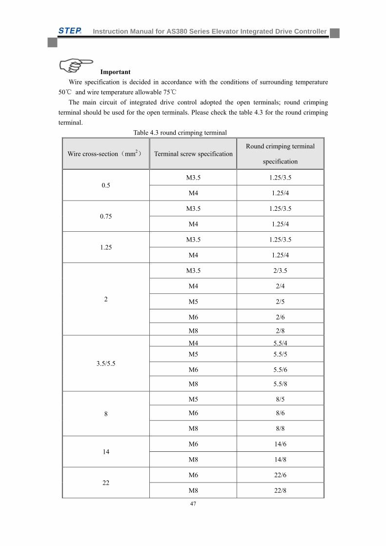
Instruction Manual for AS380 Series Elevator Integrated Drive Controller
47
Important
Wire specification is decided in accordance with the conditions of surrounding temperature
50 and wire temperature allowable 75
The main circuit of integrated drive control adopted the open terminals; round crimping
terminal should be used for the open terminals. Please check the table 4.3 for the round crimping
terminal.
Table 4.3 round crimping terminal
Wire cross-section(mm2) Terminal screw specificationRound crimping terminal
specification
0.5 M3.5 1.25/3.5
M4 1.25/4
0.75 M3.5 1.25/3.5
M4 1.25/4
1.25 M3.5 1.25/3.5
M4 1.25/4
2
M3.5 2/3.5
M4 2/4
M5 2/5
M6 2/6
M8 2/8
3.5/5.5
M4 5.5/4
M5 5.5/5
M6 5.5/6
M8 5.5/8
8
M5 8/5
M6 8/6
M8 8/8
14 M6 14/6
M8 14/8
22 M6 22/6
M8 22/8
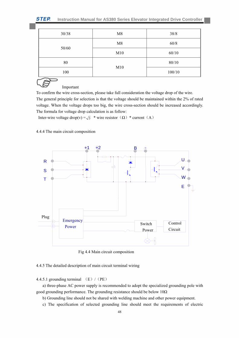
Instruction Manual for AS380 Series Elevator Integrated Drive Controller
48
30/38 M8 38/8
50/60 M8 60/8
M10 60/10
80 M10
80/10
100 100/10
Important To confirm the wire cross-section, please take full consideration the voltage drop of the wire.
The general principle for selection is that the voltage should be maintained within the 2% of rated
voltage. When the voltage drops too big, the wire cross-section should be increased accordingly.
The formula for voltage drop calculation is as follow:
Inter-wire voltage drop(v) = 3 * wire resistor(Ω)* current(A)
4.4.4 The main circuit composition
Fig 4.4 Main circuit composition
4.4.5 The detailed description of main circuit terminal wiring
4.4.5.1 grounding terminal (E)/(PE)
a) three-phase AC power supply is recommended to adopt the specialized grounding pole with
good grounding performance. The grounding resistance should be below 10Ω
b) Grounding line should not be shared with welding machine and other power equipment.
c) The specification of selected grounding line should meet the requirements of electric
+1
U
V
W
E
R
S
T
B -
Switch
Power
Control
Circuit
Emergency
Power
Plug
+2
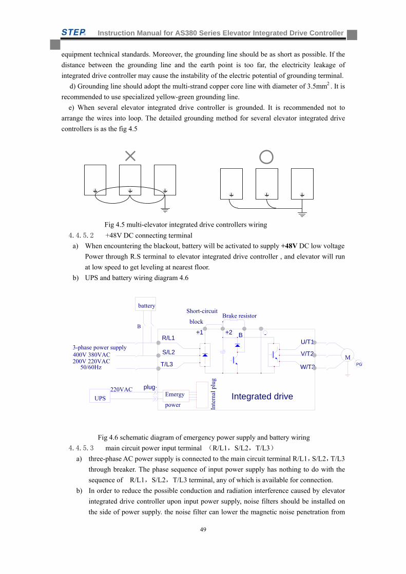
Instruction Manual for AS380 Series Elevator Integrated Drive Controller
49
equipment technical standards. Moreover, the grounding line should be as short as possible. If the
distance between the grounding line and the earth point is too far, the electricity leakage of
integrated drive controller may cause the instability of the electric potential of grounding terminal.
d) Grounding line should adopt the multi-strand copper core line with diameter of 3.5mm2 . It is
recommended to use specialized yellow-green grounding line.
e) When several elevator integrated drive controller is grounded. It is recommended not to
arrange the wires into loop. The detailed grounding method for several elevator integrated drive
controllers is as the fig 4.5
Fig 4.5 multi-elevator integrated drive controllers wiring
4.4.5.2 +48V DC connecting terminal
a) When encountering the blackout, battery will be activated to supply +48V DC low voltage
Power through R.S terminal to elevator integrated drive controller , and elevator will run
at low speed to get leveling at nearest floor.
b) UPS and battery wiring diagram 4.6
Fig 4.6 schematic diagram of emergency power supply and battery wiring
4.4.5.3 main circuit power input terminal (R/L1,S/L2,T/L3)
a) three-phase AC power supply is connected to the main circuit terminal R/L1,S/L2,T/L3
through breaker. The phase sequence of input power supply has nothing to do with the
sequence of R/L1,S/L2,T/L3 terminal, any of which is available for connection.
b) In order to reduce the possible conduction and radiation interference caused by elevator
integrated drive controller upon input power supply, noise filters should be installed on
the side of power supply. the noise filter can lower the magnetic noise penetration from
U/T1
V/T2
W/T3
R/L1
Emergy
power
plug·
+1
M400V 380VAC S/L2
PG
UPS
battery
Brake resistor
Inte
rnal
plu
g
+2
220VAC
B
3-phase power supply
Integrated drive
T/L3
-
Short-circuit
block B
50/60Hz200V 220VAC
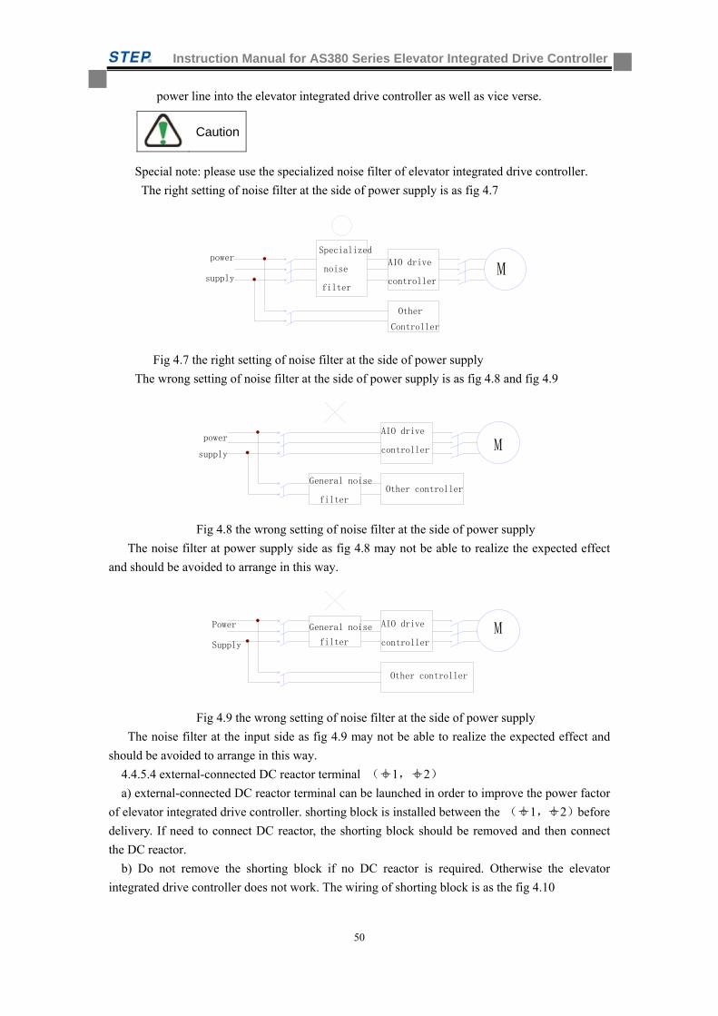
Instruction Manual for AS380 Series Elevator Integrated Drive Controller
50
power line into the elevator integrated drive controller as well as vice verse.
Special note: please use the specialized noise filter of elevator integrated drive controller.
The right setting of noise filter at the side of power supply is as fig 4.7
Fig 4.7 the right setting of noise filter at the side of power supply
The wrong setting of noise filter at the side of power supply is as fig 4.8 and fig 4.9
Fig 4.8 the wrong setting of noise filter at the side of power supply
The noise filter at power supply side as fig 4.8 may not be able to realize the expected effect
and should be avoided to arrange in this way.
Fig 4.9 the wrong setting of noise filter at the side of power supply
The noise filter at the input side as fig 4.9 may not be able to realize the expected effect and
should be avoided to arrange in this way.
4.4.5.4 external-connected DC reactor terminal ( +1, +2)
a) external-connected DC reactor terminal can be launched in order to improve the power factor
of elevator integrated drive controller. shorting block is installed between the ( +1,+2)before
delivery. If need to connect DC reactor, the shorting block should be removed and then connect
the DC reactor.
b) Do not remove the shorting block if no DC reactor is required. Otherwise the elevator
integrated drive controller does not work. The wiring of shorting block is as the fig 4.10
Other controller
General noisePower MSupply filter
AIO drive
controller
M
General noise
supply power
filter
AIO drive
controller
Other controller
AIO drive
controller
power Specialized
noise supply M
Other
filter
Controller
Caution
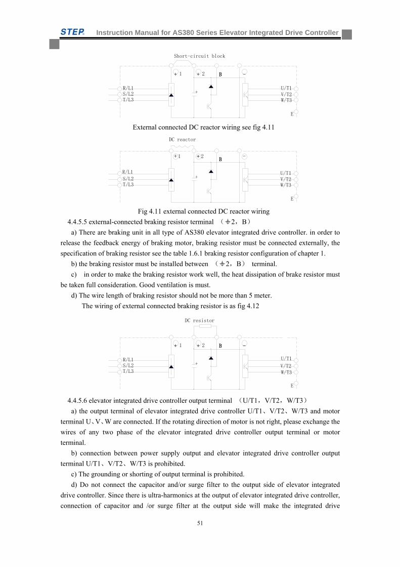
Instruction Manual for AS380 Series Elevator Integrated Drive Controller
51
External connected DC reactor wiring see fig 4.11
Fig 4.11 external connected DC reactor wiring
4.4.5.5 external-connected braking resistor terminal ( +2,B)
a) There are braking unit in all type of AS380 elevator integrated drive controller. in order to
release the feedback energy of braking motor, braking resistor must be connected externally, the
specification of braking resistor see the table 1.6.1 braking resistor configuration of chapter 1.
b) the braking resistor must be installed between ( +2,B) terminal.
c) in order to make the braking resistor work well, the heat dissipation of brake resistor must
be taken full consideration. Good ventilation is must.
d) The wire length of braking resistor should not be more than 5 meter.
The wiring of external connected braking resistor is as fig 4.12
4.4.5.6 elevator integrated drive controller output terminal (U/T1,V/T2,W/T3)
a) the output terminal of elevator integrated drive controller U/T1、V/T2、W/T3 and motor
terminal U、V、W are connected. If the rotating direction of motor is not right, please exchange the
wires of any two phase of the elevator integrated drive controller output terminal or motor
terminal.
b) connection between power supply output and elevator integrated drive controller output
terminal U/T1、V/T2、W/T3 is prohibited.
c) The grounding or shorting of output terminal is prohibited.
d) Do not connect the capacitor and/or surge filter to the output side of elevator integrated
drive controller. Since there is ultra-harmonics at the output of elevator integrated drive controller,
connection of capacitor and /or surge filter at the output side will make the integrated drive
+
BBB21 -++
E
W/T3V/T2
U/T1
DC resistor
T/L3 S/L2 R/L1
+
BBB21 -++
E
W/T3V/T2U/T1
T/L3 S/L2 R/L1
+
BBB21 -++
E
W/T3V/T2U/T1
Short-circuit block
T/L3 S/L2 R/L1
DC reactor
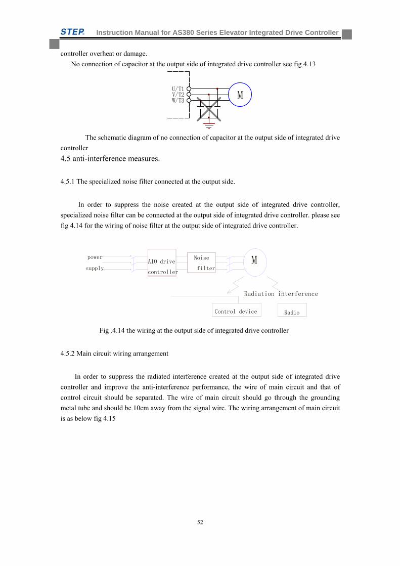
Instruction Manual for AS380 Series Elevator Integrated Drive Controller
52
controller overheat or damage.
No connection of capacitor at the output side of integrated drive controller see fig 4.13
V/T2U/T1
MW/T3
The schematic diagram of no connection of capacitor at the output side of integrated drive
controller
4.5 anti-interference measures.
4.5.1 The specialized noise filter connected at the output side.
In order to suppress the noise created at the output side of integrated drive controller,
specialized noise filter can be connected at the output side of integrated drive controller. please see
fig 4.14 for the wiring of noise filter at the output side of integrated drive controller.
Fig .4.14 the wiring at the output side of integrated drive controller
4.5.2 Main circuit wiring arrangement
In order to suppress the radiated interference created at the output side of integrated drive
controller and improve the anti-interference performance, the wire of main circuit and that of
control circuit should be separated. The wire of main circuit should go through the grounding
metal tube and should be 10cm away from the signal wire. The wiring arrangement of main circuit
is as below fig 4.15
Noise
filter
Control device Radio
Radiation interference
power
supply MAIO drive
controller
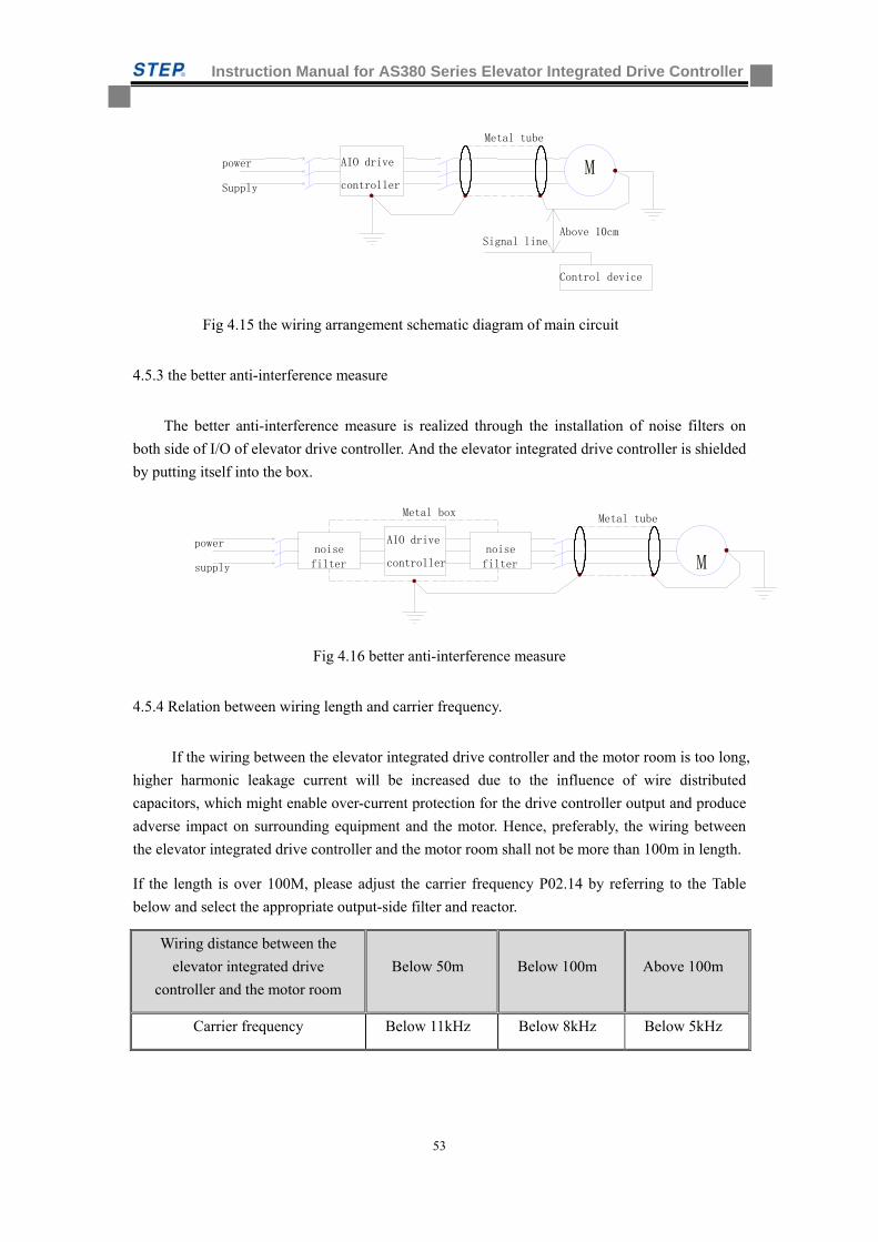
Instruction Manual for AS380 Series Elevator Integrated Drive Controller
53
Fig 4.15 the wiring arrangement schematic diagram of main circuit
4.5.3 the better anti-interference measure
The better anti-interference measure is realized through the installation of noise filters on
both side of I/O of elevator drive controller. And the elevator integrated drive controller is shielded
by putting itself into the box.
Fig 4.16 better anti-interference measure
4.5.4 Relation between wiring length and carrier frequency.
If the wiring between the elevator integrated drive controller and the motor room is too long,
higher harmonic leakage current will be increased due to the influence of wire distributed
capacitors, which might enable over-current protection for the drive controller output and produce
adverse impact on surrounding equipment and the motor. Hence, preferably, the wiring between
the elevator integrated drive controller and the motor room shall not be more than 100m in length.
If the length is over 100M, please adjust the carrier frequency P02.14 by referring to the Table
below and select the appropriate output-side filter and reactor.
Wiring distance between the
elevator integrated drive
controller and the motor room
Below 50m Below 100m Above 100m
Carrier frequency Below 11kHz Below 8kHz Below 5kHz
M
power
supply
Metal tube
noise filter
noisefilter
Metal box
AIO drive
controller
M
Metal tube
Supply
power
Above 10cm
Control device
Signal line
AIO drive
controller
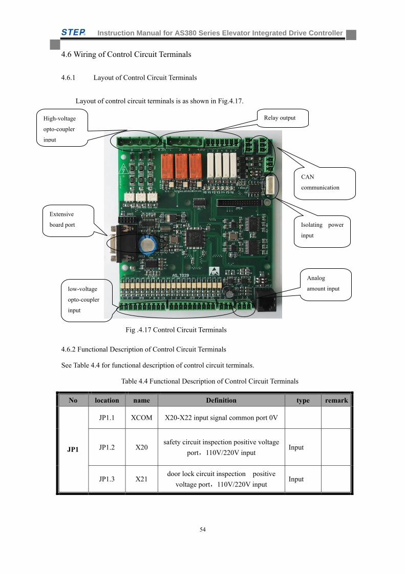
Instruction Manual for AS380 Series Elevator Integrated Drive Controller
54
4.6 Wiring of Control Circuit Terminals
4.6.1 Layout of Control Circuit Terminals
Layout of control circuit terminals is as shown in Fig.4.17.
Fig .4.17 Control Circuit Terminals
4.6.2 Functional Description of Control Circuit Terminals
See Table 4.4 for functional description of control circuit terminals.
Table 4.4 Functional Description of Control Circuit Terminals
No location name Definition type remark
JP1
JP1.1 XCOM X20-X22 input signal common port 0V
JP1.2 X20 safety circuit inspection positive voltage
port,110V/220V input Input
JP1.3 X21 door lock circuit inspection positive
voltage port,110V/220V input Input
CAN
communication
Isolating power
input
Analog
amount input low-voltage
opto-coupler
input
Extensive
board port
Relay output High-voltage
opto-coupler
input
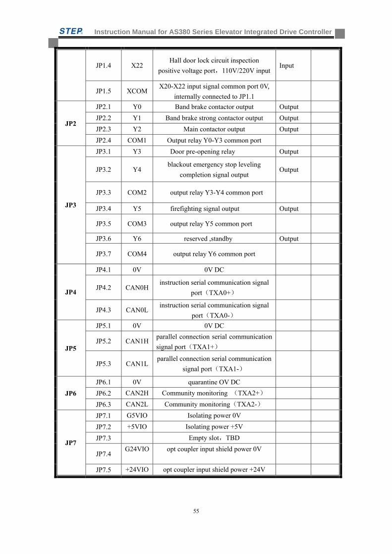
Instruction Manual for AS380 Series Elevator Integrated Drive Controller
55
JP1.4 X22 Hall door lock circuit inspection
positive voltage port,110V/220V inputInput
JP1.5 XCOM X20-X22 input signal common port 0V,
internally connected to JP1.1
JP2
JP2.1 Y0 Band brake contactor output Output
JP2.2 Y1 Band brake strong contactor output Output
JP2.3 Y2 Main contactor output Output
JP2.4 COM1 Output relay Y0-Y3 common port
JP3
JP3.1 Y3 Door pre-opening relay Output
JP3.2 Y4 blackout emergency stop leveling
completion signal output Output
JP3.3 COM2 output relay Y3-Y4 common port
JP3.4 Y5 firefighting signal output Output
JP3.5 COM3 output relay Y5 common port
JP3.6 Y6 reserved ,standby Output
JP3.7 COM4 output relay Y6 common port
JP4
JP4.1 0V 0V DC
JP4.2 CAN0H instruction serial communication signal
port(TXA0+)
JP4.3 CAN0L instruction serial communication signal
port(TXA0-)
JP5
JP5.1 0V 0V DC
JP5.2 CAN1H parallel connection serial communication
signal port(TXA1+)
JP5.3 CAN1L parallel connection serial communication
signal port(TXA1-)
JP6
JP6.1 0V quarantine OV DC
JP6.2 CAN2H Community monitoring (TXA2+)
JP6.3 CAN2L Community monitoring(TXA2-)
JP7
JP7.1 G5VIO Isolating power 0V
JP7.2 +5VIO Isolating power +5V
JP7.3 Empty slot,TBD
JP7.4 G24VIO opt coupler input shield power 0V
JP7.5 +24VIO opt coupler input shield power +24V
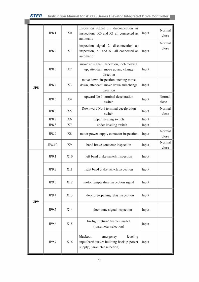
Instruction Manual for AS380 Series Elevator Integrated Drive Controller
56
JP8
JP8.1 X0 Inspection signal 1, disconnection as
inspection,X0 and X1 all connected as
automatic
Input Normal
close
JP8.2 X1
inspection signal 2, disconnection as
inspection, X0 and X1 all connected as
automatic
Input
Normal
close
JP8.3 X2
move up signal ,inspection, inch moving
up, attendant, move up and change
direction
Input
JP8.4 X3
move down, inspection, inching move
down, attendant, move down and change
direction
Input
JP8.5 X4 upward No 1 terminal deceleration
switch Input
Normal
close
JP8.6 X5 Downward No 1 terminal deceleration
switch Input
Normal
close
JP8.7 X6 upper leveling switch Input
JP8.8 X7 under leveling switch Input
JP8.9 X8 motor power supply contactor inspection Input Normal
close
JP8.10 X9 band brake contactor inspection Input Normal
close
JP9
JP9.1 X10 left band brake switch Inspection Input
JP9.2 X11 right band brake switch inspection Input
JP9.3 X12 motor temperature inspection signal Input
JP9.4 X13 door pre-opening relay inspection Input
JP9.5 X14 door zone signal inspection Input
JP9.6 X15 firefight return/ firemen switch
( parameter selection) Input
JP9.7 X16
blackout emergency leveling
input/earthquake/ building backup power
supply( parameter selection)
Input
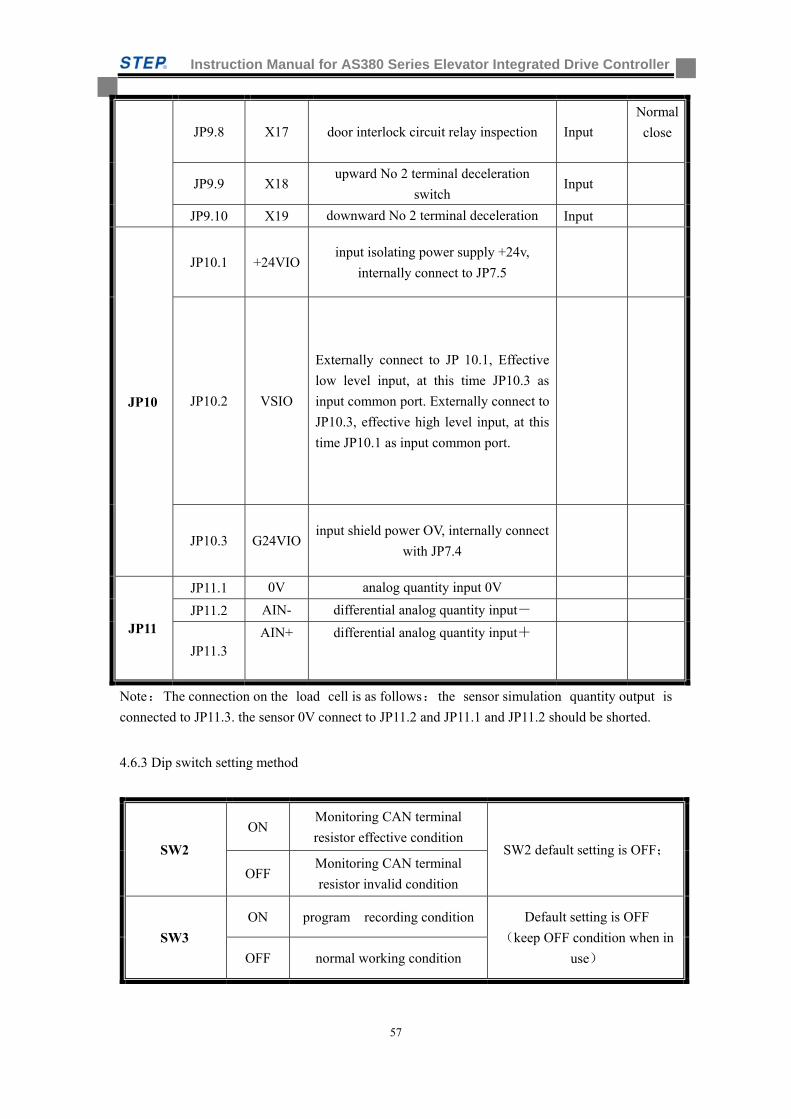
Instruction Manual for AS380 Series Elevator Integrated Drive Controller
57
JP9.8 X17 door interlock circuit relay inspection Input
Normal
close
JP9.9 X18 upward No 2 terminal deceleration
switch Input
JP9.10 X19 downward No 2 terminal deceleration Input
JP10
JP10.1 +24VIO input isolating power supply +24v,
internally connect to JP7.5
JP10.2 VSIO
Externally connect to JP 10.1, Effective
low level input, at this time JP10.3 as
input common port. Externally connect to
JP10.3, effective high level input, at this
time JP10.1 as input common port.
JP10.3 G24VIO input shield power OV, internally connect
with JP7.4
JP11
JP11.1 0V analog quantity input 0V
JP11.2 AIN- differential analog quantity input-
JP11.3 AIN+ differential analog quantity input+
Note:The connection on the load cell is as follows: the sensor simulation quantity output is
connected to JP11.3. the sensor 0V connect to JP11.2 and JP11.1 and JP11.2 should be shorted.
4.6.3 Dip switch setting method
SW2
ON Monitoring CAN terminal
resistor effective condition SW2 default setting is OFF;
OFF Monitoring CAN terminal
resistor invalid condition
SW3
ON program recording condition Default setting is OFF
(keep OFF condition when in
use) OFF normal working condition
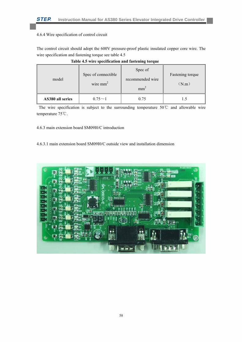
Instruction Manual for AS380 Series Elevator Integrated Drive Controller
58
4.6.4 Wire specification of control circuit
The control circuit should adopt the 600V pressure-proof plastic insulated copper core wire. The
wire specification and fastening torque see table 4.5
Table 4.5 wire specification and fastening torque
model Spec of connectible
wire mm2
Spec of
recommended wire
mm2
Fastening torque
(N.m)
AS380 all series 0.75~1 0.75 1.5
The wire specification is subject to the surrounding temperature 50 and allowable wire
temperature 75.
4.6.3 main extension board SM09I0/C introduction
4.6.3.1 main extension board SM09I0/C outside view and installation dimension
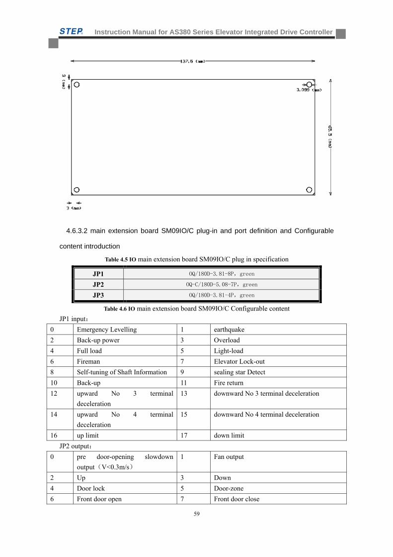
Instruction Manual for AS380 Series Elevator Integrated Drive Controller
59
4.6.3.2 main extension board SM09IO/C plug-in and port definition and Configurable
content introduction
Table 4.5 IO main extension board SM09IO/C plug in specification
Table 4.6 IO main extension board SM09IO/C Configurable content
JP1 input:
0 Emergency Levelling 1 earthquake
2 Back-up power 3 Overload
4 Full load 5 Light-load
6 Fireman 7 Elevator Lock-out
8 Self-tuning of Shaft Information 9 sealing star Detect
10 Back-up 11 Fire return
12 upward No 3 terminal
deceleration
13 downward No 3 terminal deceleration
14 upward No 4 terminal
deceleration
15 downward No 4 terminal deceleration
16 up limit 17 down limit
JP2 output:
0 pre door-opening slowdown
output(V<0.3m/s)
1 Fan output
2 Up 3 Down
4 Door lock 5 Door-zone
6 Front door open 7 Front door close
JP1 OQ/180D-3.81-8P,green
JP2 OQ-C/180D-5.08-7P,green
JP3 OQ/180D-3.81-4P,green
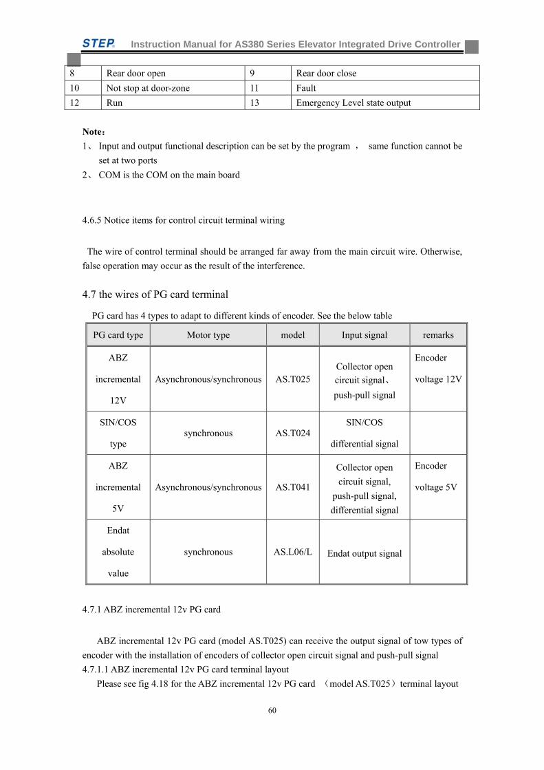
Instruction Manual for AS380 Series Elevator Integrated Drive Controller
60
8 Rear door open 9 Rear door close
10 Not stop at door-zone 11 Fault
12 Run 13 Emergency Level state output
Note:
1、 Input and output functional description can be set by the program , same function cannot be
set at two ports
2、 COM is the COM on the main board
4.6.5 Notice items for control circuit terminal wiring
The wire of control terminal should be arranged far away from the main circuit wire. Otherwise,
false operation may occur as the result of the interference.
4.7 the wires of PG card terminal
PG card has 4 types to adapt to different kinds of encoder. See the below table
PG card type Motor type model Input signal remarks
ABZ
incremental
12V
Asynchronous/synchronous AS.T025 Collector open
circuit signal、
push-pull signal
Encoder
voltage 12V
SIN/COS
type synchronous AS.T024
SIN/COS
differential signal
ABZ
incremental
5V
Asynchronous/synchronous AS.T041
Collector open
circuit signal,
push-pull signal,
differential signal
Encoder
voltage 5V
Endat
absolute
value
synchronous AS.L06/L Endat output signal
4.7.1 ABZ incremental 12v PG card
ABZ incremental 12v PG card (model AS.T025) can receive the output signal of tow types of
encoder with the installation of encoders of collector open circuit signal and push-pull signal
4.7.1.1 ABZ incremental 12v PG card terminal layout
Please see fig 4.18 for the ABZ incremental 12v PG card (model AS.T025)terminal layout
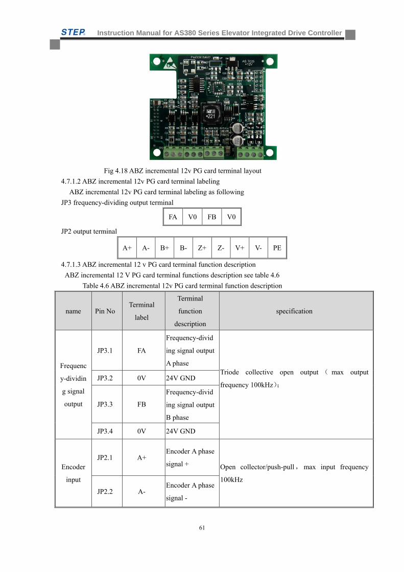
Instruction Manual for AS380 Series Elevator Integrated Drive Controller
61
Fig 4.18 ABZ incremental 12v PG card terminal layout
4.7.1.2 ABZ incremental 12v PG card terminal labeling
ABZ incremental 12v PG card terminal labeling as following
JP3 frequency-dividing output terminal
FA V0 FB V0
JP2 output terminal
A+ A- B+ B- Z+ Z- V+ V- PE
4.7.1.3 ABZ incremental 12 v PG card terminal function description
ABZ incremental 12 V PG card terminal functions description see table 4.6
Table 4.6 ABZ incremental 12v PG card terminal function description
name Pin No Terminal
label
Terminal
function
description
specification
Frequenc
y-dividin
g signal
output
JP3.1 FA
Frequency-divid
ing signal output
A phase Triode collective open output ( max output
frequency 100kHz);
JP3.2 0V 24V GND
JP3.3 FB
Frequency-divid
ing signal output
B phase
JP3.4 0V 24V GND
Encoder
input
JP2.1 A+ Encoder A phase
signal + Open collector/push-pull,max input frequency
100kHz
JP2.2 A- Encoder A phase
signal -
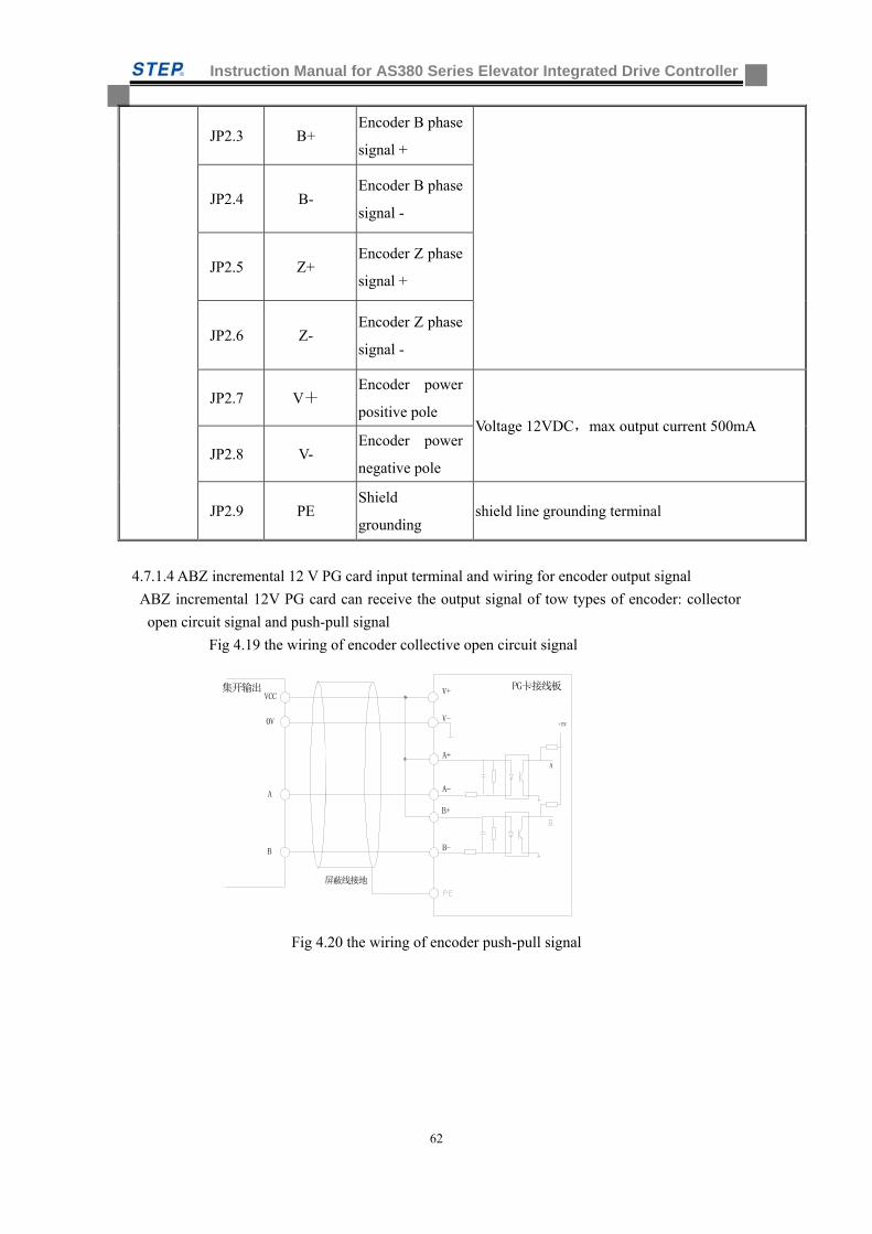
Instruction Manual for AS380 Series Elevator Integrated Drive Controller
62
JP2.3 B+ Encoder B phase
signal +
JP2.4 B- Encoder B phase
signal -
JP2.5 Z+ Encoder Z phase
signal +
JP2.6 Z- Encoder Z phase
signal -
JP2.7 V+ Encoder power
positive pole Voltage 12VDC,max output current 500mA
JP2.8 V- Encoder power
negative pole
JP2.9 PE Shield
grounding shield line grounding terminal
4.7.1.4 ABZ incremental 12 V PG card input terminal and wiring for encoder output signal
ABZ incremental 12V PG card can receive the output signal of tow types of encoder: collector
open circuit signal and push-pull signal
Fig 4.19 the wiring of encoder collective open circuit signal
集开输出VCC
0V
A
B
A-
B-
A+
B+
A
PG卡接线板
+5V
屏蔽线接地
V+
V-
Fig 4.20 the wiring of encoder push-pull signal
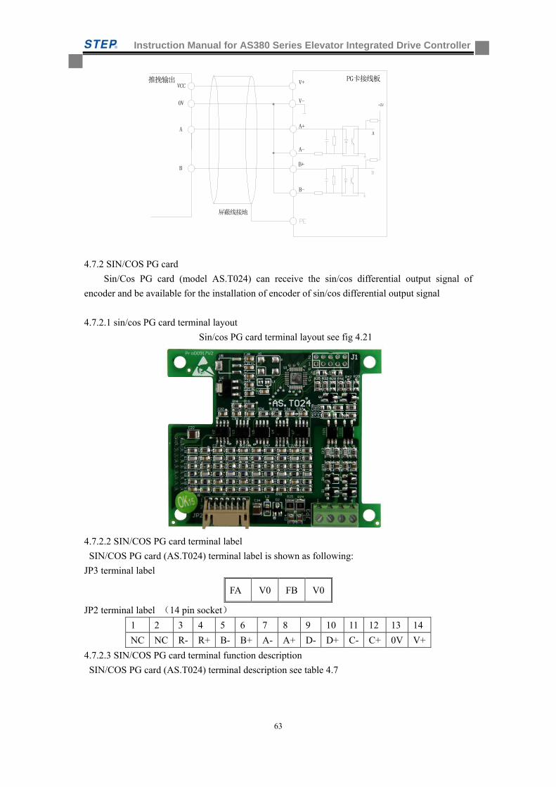
Instruction Manual for AS380 Series Elevator Integrated Drive Controller
63
推挽输出VCC
0V
A
B
A-
B-
A+
B+
A
PG卡接线板
+5V
屏蔽线接地
V+
V-
4.7.2 SIN/COS PG card
Sin/Cos PG card (model AS.T024) can receive the sin/cos differential output signal of
encoder and be available for the installation of encoder of sin/cos differential output signal
4.7.2.1 sin/cos PG card terminal layout
Sin/cos PG card terminal layout see fig 4.21
4.7.2.2 SIN/COS PG card terminal label
SIN/COS PG card (AS.T024) terminal label is shown as following:
JP3 terminal label
FA V0 FB V0
JP2 terminal label (14 pin socket)
1 2 3 4 5 6 7 8 9 10 11 12 13 14
NC NC R- R+ B- B+ A- A+ D- D+ C- C+ 0V V+
4.7.2.3 SIN/COS PG card terminal function description
SIN/COS PG card (AS.T024) terminal description see table 4.7
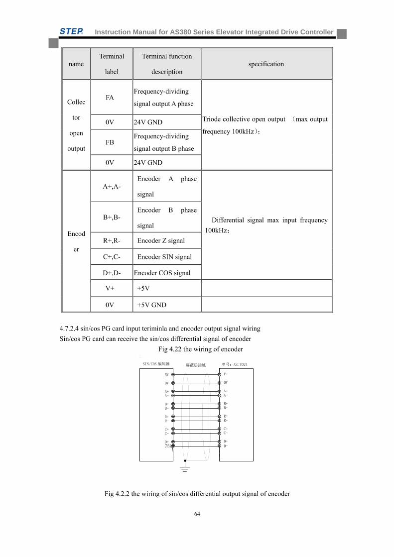
Instruction Manual for AS380 Series Elevator Integrated Drive Controller
64
name Terminal
label
Terminal function
description specification
Collec
tor
open
output
FA Frequency-dividing
signal output A phase
Triode collective open output (max output
frequency 100kHz); 0V 24V GND
FB Frequency-dividing
signal output B phase
0V 24V GND
Encod
er
A+,A- Encoder A phase
signal
Differential signal max input frequency
100kHz;
B+,B- Encoder B phase
signal
R+,R- Encoder Z signal
C+,C- Encoder SIN signal
D+,D- Encoder COS signal
V+ +5V
0V +5V GND
4.7.2.4 sin/cos PG card input teriminla and encoder output signal wiring
Sin/cos PG card can receive the sin/cos differential signal of encoder
Fig 4.22 the wiring of encoder
Fig 4.2.2 the wiring of sin/cos differential output signal of encoder
SIN/COS 编码器
5V
0V
A+
屏蔽层接地
A-
B+B-
R+R-
C+C-
D+75kW
V+
0V
A+A-
B+B-
R+R-
C+C-
D+D-
型号:AS.T024
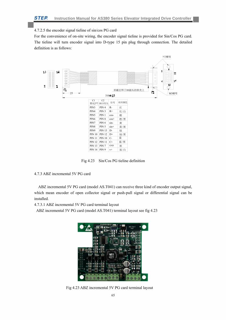
Instruction Manual for AS380 Series Elevator Integrated Drive Controller
65
4.7.2.5 the encoder signal tieline of sin/cos PG card
For the convenience of on-site wiring, the encoder signal tieline is provided for Sin/Cos PG card.
The tieline will turn encoder signal into D-type 15 pin plug through connection. The detailed
definition is as follows:
M3螺母
M3螺母
屏蔽层焊于DB插头的铁壳上
310
C1 塑壳2*7
C2 DB15母头
PIN3
PIN4
PIN5
PIN6
PIN7
PIN8
PIN9
PIN 10
PIN 11
PIN 12 PIN 11
PIN 10
PIN 12
PIN 13
PIN 5
PIN 6
PIN 8
PIN 1
PIN 3
PIN 4
PIN 13
PIN 14 PIN 9
PIN 7
25
对应颜色信号
红
红/白
橙
黄/黑
橙/黑
绿
绿/黑
黑
黑/白
黄
蓝/黑
蓝
cos-
cos+
sin-
sin+
D-
D+
C-
C+GND
v+
R-
R+
Fig 4.23 Sin/Cos PG tieline definition
4.7.3 ABZ incremental 5V PG card
ABZ incremental 5V PG card (model AS.T041) can receive three kind of encoder output signal,
which mean encoder of open collector signal or push-pull signal or differential signal can be
installed.
4.7.3.1 ABZ incremental 5V PG card terminal layout
ABZ incremental 5V PG card (model AS.T041) terminal layout see fig 4.23
Fig 4.23 ABZ incremental 5V PG card terminal layout
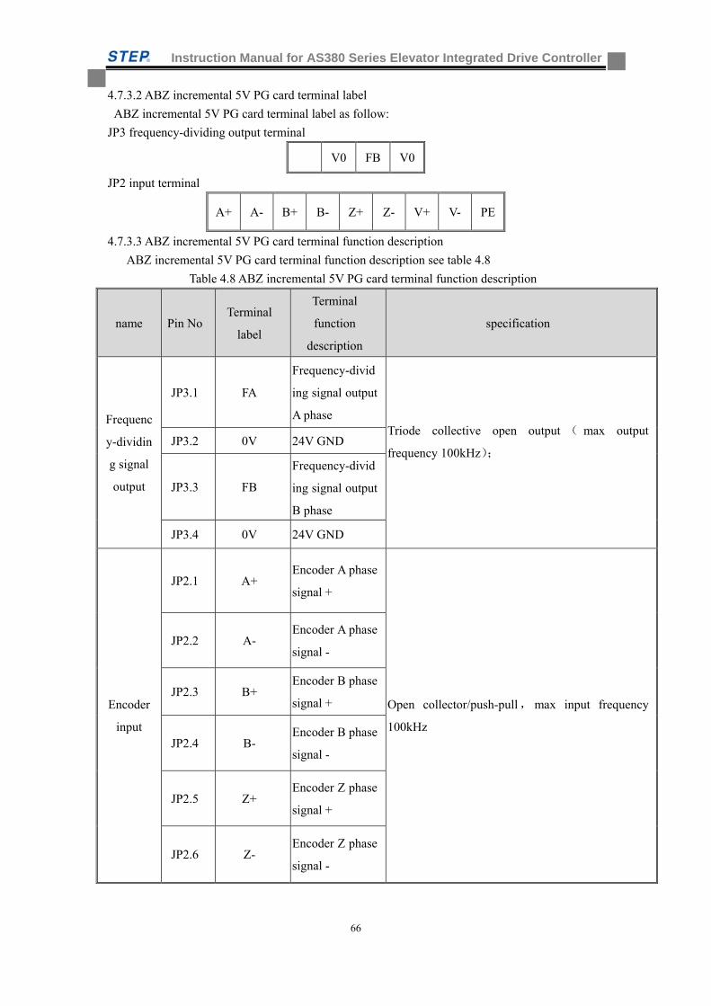
Instruction Manual for AS380 Series Elevator Integrated Drive Controller
66
4.7.3.2 ABZ incremental 5V PG card terminal label
ABZ incremental 5V PG card terminal label as follow:
JP3 frequency-dividing output terminal
V0 FB V0
JP2 input terminal
A+ A- B+ B- Z+ Z- V+ V- PE
4.7.3.3 ABZ incremental 5V PG card terminal function description
ABZ incremental 5V PG card terminal function description see table 4.8
Table 4.8 ABZ incremental 5V PG card terminal function description
name Pin No Terminal
label
Terminal
function
description
specification
Frequenc
y-dividin
g signal
output
JP3.1 FA
Frequency-divid
ing signal output
A phase Triode collective open output ( max output
frequency 100kHz);
JP3.2 0V 24V GND
JP3.3 FB
Frequency-divid
ing signal output
B phase
JP3.4 0V 24V GND
Encoder
input
JP2.1 A+ Encoder A phase
signal +
Open collector/push-pull,max input frequency
100kHz
JP2.2 A- Encoder A phase
signal -
JP2.3 B+ Encoder B phase
signal +
JP2.4 B- Encoder B phase
signal -
JP2.5 Z+ Encoder Z phase
signal +
JP2.6 Z- Encoder Z phase
signal -
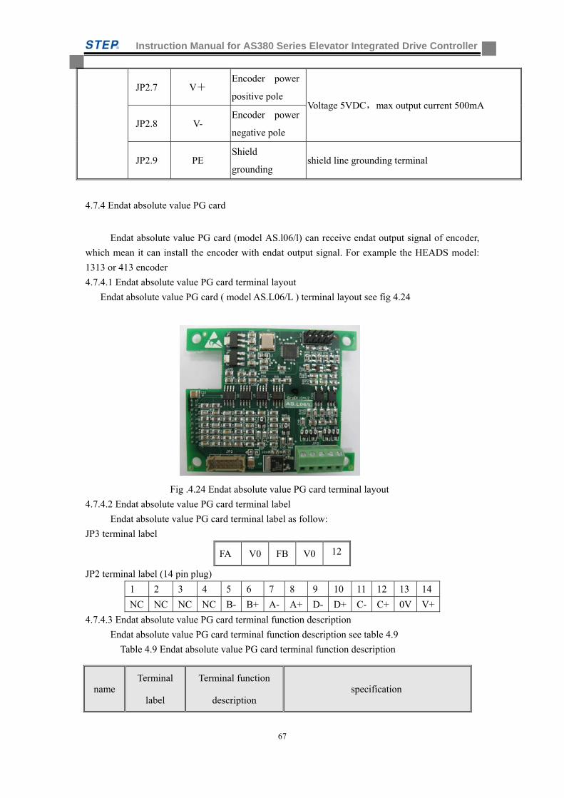
Instruction Manual for AS380 Series Elevator Integrated Drive Controller
67
JP2.7 V+ Encoder power
positive pole Voltage 5VDC,max output current 500mA
JP2.8 V- Encoder power
negative pole
JP2.9 PE Shield
grounding shield line grounding terminal
4.7.4 Endat absolute value PG card
Endat absolute value PG card (model AS.l06/l) can receive endat output signal of encoder,
which mean it can install the encoder with endat output signal. For example the HEADS model:
1313 or 413 encoder
4.7.4.1 Endat absolute value PG card terminal layout
Endat absolute value PG card ( model AS.L06/L ) terminal layout see fig 4.24
Fig .4.24 Endat absolute value PG card terminal layout
4.7.4.2 Endat absolute value PG card terminal label
Endat absolute value PG card terminal label as follow:
JP3 terminal label
FA V0 FB V0 12
JP2 terminal label (14 pin plug)
1 2 3 4 5 6 7 8 9 10 11 12 13 14
NC NC NC NC B- B+ A- A+ D- D+ C- C+ 0V V+
4.7.4.3 Endat absolute value PG card terminal function description
Endat absolute value PG card terminal function description see table 4.9
Table 4.9 Endat absolute value PG card terminal function description
name Terminal
label
Terminal function
description specification
Instruction Manual for AS380 Series Elevator Integrated Drive Controller
68
4.7.4.4 Endat absolute value PG card encoder signal tieline
For the convenience of on-site wiring, encoder signal tieline is provided for Endat absolute value
PG card. The tieline can turn encoder signal into D-type 15 pin plug through connection. The
detailed definition is as follow:
Collec
tor
open
signal
output
FA Frequency-dividing
signal output A phase
triode collective open output (max output
frequency 100khz) max output current
50mA,
0V GND
FB Frequency-dividing
signal output B phase
0V GND
+12V 12V power output
Encod
er
input
A+,A- Encoder A phase
signal
differential signal, max input frequency
100kHz
B+,B- Encoder B phase
signal
C+,C- Encoder clock signal
D+,D- Encoder data signal
V+ +5V
0V +5V 的 GND
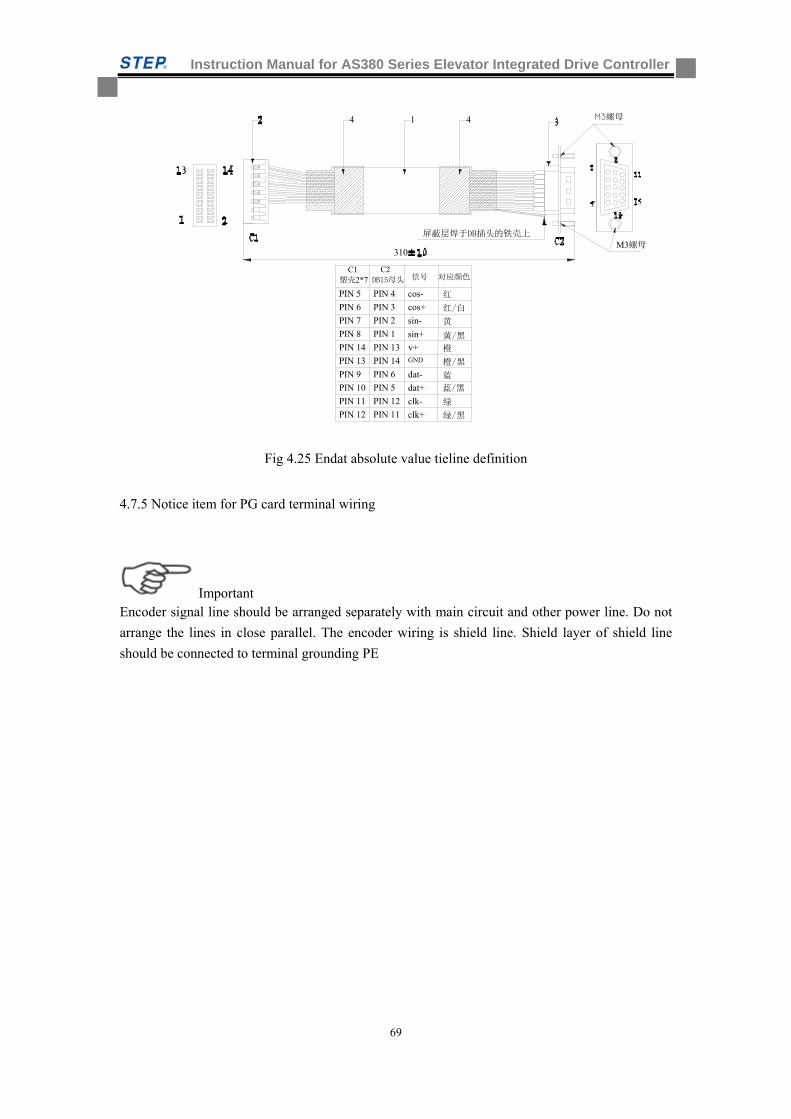
Instruction Manual for AS380 Series Elevator Integrated Drive Controller
69
M3螺母
M3螺母
屏蔽层焊于DB插头的铁壳上
310
1 44
C1 塑壳2*7
C2 DB15母头 信号
PIN 5
PIN 6
PIN 7
PIN 8
PIN 14
PIN 13
PIN 9
PIN 10
PIN 11
PIN 12 PIN 11
PIN 12
PIN 5
PIN 6
PIN 14
PIN 13
PIN 1
PIN 2
PIN 3
PIN 4 cos-
对应颜色
cos+
sin-
v+GND
dat-
dat+
clk-
clk+
sin+
红
黄
橙
红/白
黄/黑
橙/黑
蓝/黑
蓝
绿
绿/黑
Fig 4.25 Endat absolute value tieline definition
4.7.5 Notice item for PG card terminal wiring
Important Encoder signal line should be arranged separately with main circuit and other power line. Do not
arrange the lines in close parallel. The encoder wiring is shield line. Shield layer of shield line
should be connected to terminal grounding PE
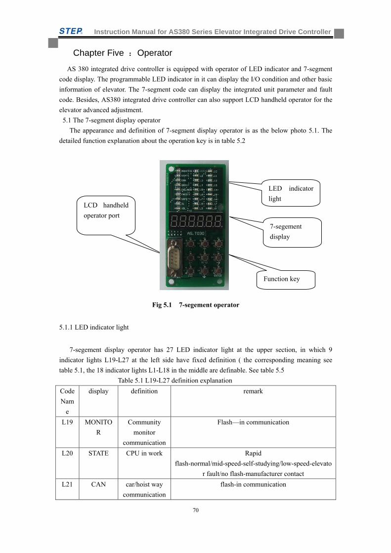
Instruction Manual for AS380 Series Elevator Integrated Drive Controller
70
Chapter Five :Operator
AS 380 integrated drive controller is equipped with operator of LED indicator and 7-segment
code display. The programmable LED indicator in it can display the I/O condition and other basic
information of elevator. The 7-segment code can display the integrated unit parameter and fault
code. Besides, AS380 integrated drive controller can also support LCD handheld operator for the
elevator advanced adjustment.
5.1 The 7-segment display operator
The appearance and definition of 7-segment display operator is as the below photo 5.1. The
detailed function explanation about the operation key is in table 5.2
Fig 5.1 7-segement operator
5.1.1 LED indicator light
7-segement display operator has 27 LED indicator light at the upper section, in which 9
indicator lights L19-L27 at the left side have fixed definition ( the corresponding meaning see
table 5.1, the 18 indicator lights L1-L18 in the middle are definable. See table 5.5
Table 5.1 L19-L27 definition explanation
Code
Nam
e
display definition remark
L19 MONITO
R
Community
monitor
communication
Flash—in communication
L20 STATE CPU in work Rapid
flash-normal/mid-speed-self-studying/low-speed-elevato
r fault/no flash-manufacturer contact
L21 CAN car/hoist way
communication
flash-in communication
LED indicator
light
7-segement
display
Function key
LCD handheld
operator port
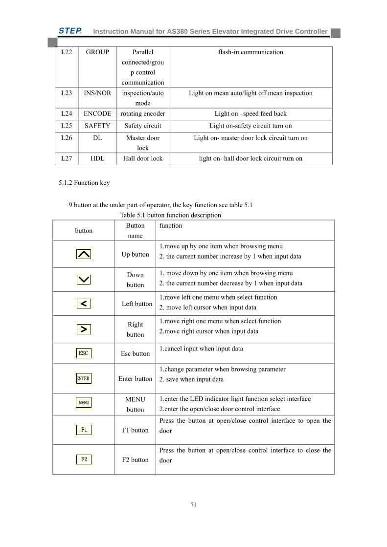
Instruction Manual for AS380 Series Elevator Integrated Drive Controller
71
L22 GROUP Parallel
connected/grou
p control
communication
flash-in communication
L23 INS/NOR inspection/auto
mode
Light on mean auto/light off mean inspection
L24 ENCODE rotating encoder Light on –speed feed back
L25 SAFETY Safety circuit Light on-safety circuit turn on
L26 DL Master door
lock
Light on- master door lock circuit turn on
L27 HDL Hall door lock light on- hall door lock circuit turn on
5.1.2 Function key
9 button at the under part of operator, the key function see table 5.1
Table 5.1 button function description
button Button
name
function
Up button
1.move up by one item when browsing menu
2. the current number increase by 1 when input data
Down
button
1. move down by one item when browsing menu
2. the current number decrease by 1 when input data
Left button
1.move left one menu when select function
2. move left cursor when input data
Right
button
1.move right one menu when select function
2.move right cursor when input data
ESC
Esc button 1.cancel input when input data
ENTER
Enter button
1.change parameter when browsing parameter
2. save when input data
MENU
button
1.enter the LED indicator light function select interface
2.enter the open/close door control interface
F1
F1 button
Press the button at open/close control interface to open the
door
F2
F2 button
Press the button at open/close control interface to close the
door
MENU
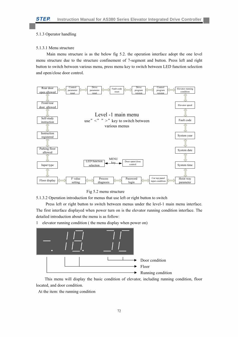
Instruction Manual for AS380 Series Elevator Integrated Drive Controller
72
5.1.3 Operator handling
5.1.3.1 Menu structure
Main menu structure is as the below fig 5.2. the operation interface adopt the one level
menu structure due to the structure confinement of 7-segment and button. Press left and right
button to switch between various menu, press menu key to switch between LED function selection
and open/close door control.
Instruction registered
Self-study instruction
Front/rear
door allowed
Fault code
System year
System date
System time
Hoist way parameter
Car top panel input condition
Password login
Process diagnosis
Level -1 main menuuse”<””>”key to switch between
various menus
F value setting
Control parameter
reset
LED function selection
Door open/close control
MENU key
Rear door open allowed
Drive parameter
reset
Floor display
Input type
Parking floor allowed
Elevator speed
Elevator running condition
Fault code reset
Drive program version
Control program version
Fig 5.2 menu structure
5.1.3.2 Operation introduction for menus that use left or right button to switch
Press left or right button to switch between menus under the level-1 main menu interface.
The first interface displayed when power turn on is the elevator running condition interface. The
detailed introduction about the menu is as follow:
1 elevator running condition ( the menu display when power on)
Door condition
Floor
Running condition
This menu will display the basic condition of elevator, including running condition, floor
located, and door condition.
At the item: the running condition
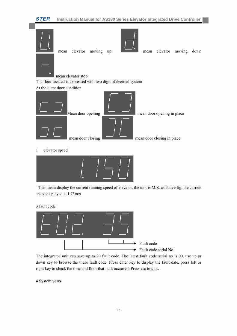
Instruction Manual for AS380 Series Elevator Integrated Drive Controller
73
mean elevator moving up mean elevator moving down
mean elevator stop The floor located is expressed with two digit of decimal system
At the item: door condition
Mean door opening mean door opening in place
mean door closing mean door closing in place
1 elevator speed
This menu display the current running speed of elevator, the unit is M/S. as above fig, the current
speed displayed is 1.75m/s
3 fault code
Fault code
Fault code serial No
The integrated unit can save up to 20 fault code. The latest fault code serial no is 00. use up or
down key to browse the these fault code. Press enter key to display the fault date, press left or
right key to check the time and floor that fault occurred. Press esc to quit.
4 System years
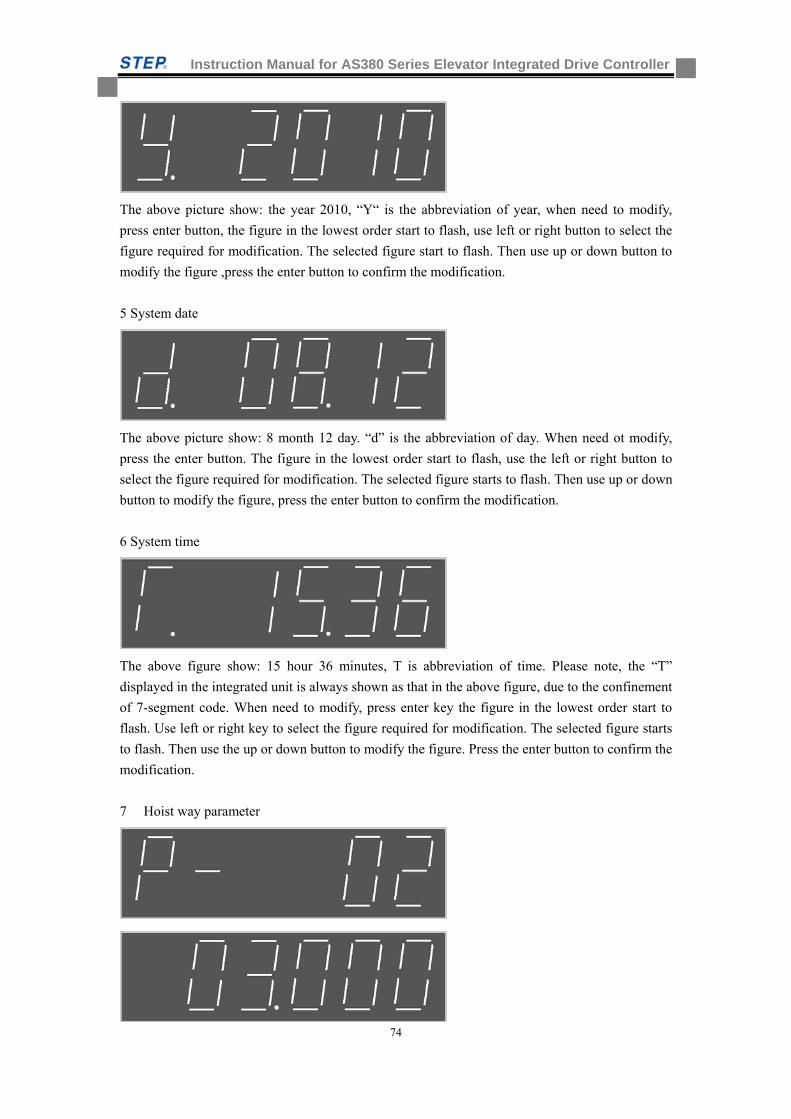
Instruction Manual for AS380 Series Elevator Integrated Drive Controller
74
The above picture show: the year 2010, “Y“ is the abbreviation of year, when need to modify,
press enter button, the figure in the lowest order start to flash, use left or right button to select the
figure required for modification. The selected figure start to flash. Then use up or down button to
modify the figure ,press the enter button to confirm the modification.
5 System date
The above picture show: 8 month 12 day. “d” is the abbreviation of day. When need ot modify,
press the enter button. The figure in the lowest order start to flash, use the left or right button to
select the figure required for modification. The selected figure starts to flash. Then use up or down
button to modify the figure, press the enter button to confirm the modification.
6 System time
The above figure show: 15 hour 36 minutes, T is abbreviation of time. Please note, the “T”
displayed in the integrated unit is always shown as that in the above figure, due to the confinement
of 7-segment code. When need to modify, press enter key the figure in the lowest order start to
flash. Use left or right key to select the figure required for modification. The selected figure starts
to flash. Then use the up or down button to modify the figure. Press the enter button to confirm the
modification.
7 Hoist way parameter
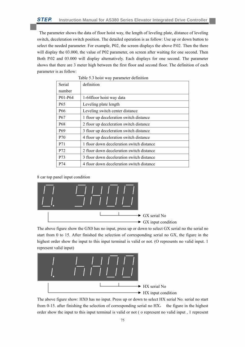
Instruction Manual for AS380 Series Elevator Integrated Drive Controller
75
The parameter shows the data of floor hoist way, the length of leveling plate, distance of leveling
switch, deceleration switch position. The detailed operation is as follow: Use up or down button to
select the needed parameter. For example, P02, the screen displays the above P.02. Then the there
will display the 03.000, the value of P02 parameter, on screen after waiting for one second. Then
Both P.02 and 03.000 will display alternatively. Each displays for one second. The parameter
shows that there are 3 meter high between the first floor and second floor. The definition of each
parameter is as follow:
Table 5.3 hoist way parameter definition
Serial
number
definition
P01-P64 1-64floor hoist way data
P65 Leveling plate length
P66 Leveling switch center distance
P67 1 floor up deceleration switch distance
P68 2 floor up deceleration switch distance
P69 3 floor up deceleration switch distance
P70 4 floor up deceleration switch distance
P71 1 floor down deceleration switch distance
P72 2 floor down deceleration switch distance
P73 3 floor down deceleration switch distance
P74 4 floor down deceleration switch distance
8 car top panel input condition
GX serial No
GX input condition
The above figure show the GX0 has no input, press up or down to select GX serial no the serial no
start from 0 to 15. After finished the selection of corresponding serial no GX, the figure in the
highest order show the input to this input terminal is valid or not. (O represents no valid input. 1
represent valid input)
HX serial No
HX input condition
The above figure show: HX0 has no input. Press up or down to select HX serial No. serial no start
from 0-15. after finishing the selection of corresponding serial no HX, the figure in the highest
order show the input to this input terminal is valid or not ( o represent no valid input , 1 represent
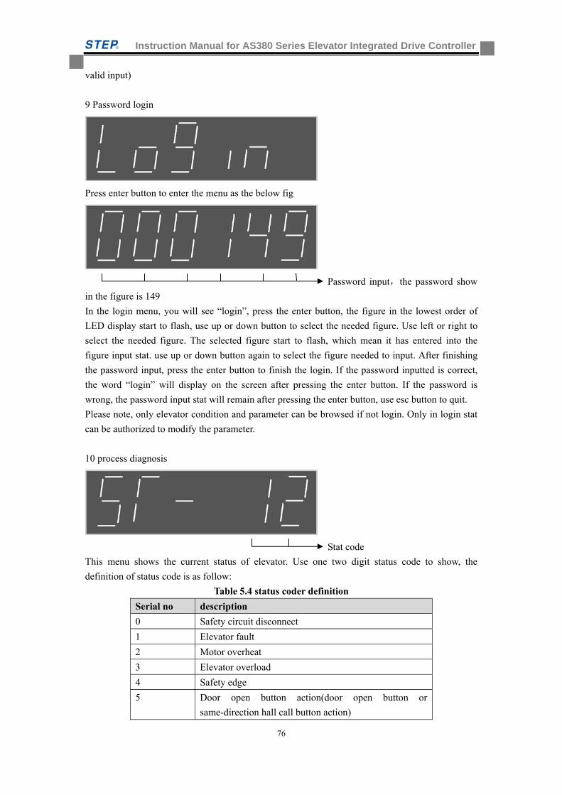
Instruction Manual for AS380 Series Elevator Integrated Drive Controller
76
valid input)
9 Password login
Press enter button to enter the menu as the below fig
Password input,the password show
in the figure is 149
In the login menu, you will see “login”, press the enter button, the figure in the lowest order of
LED display start to flash, use up or down button to select the needed figure. Use left or right to
select the needed figure. The selected figure start to flash, which mean it has entered into the
figure input stat. use up or down button again to select the figure needed to input. After finishing
the password input, press the enter button to finish the login. If the password inputted is correct,
the word “login” will display on the screen after pressing the enter button. If the password is
wrong, the password input stat will remain after pressing the enter button, use esc button to quit.
Please note, only elevator condition and parameter can be browsed if not login. Only in login stat
can be authorized to modify the parameter.
10 process diagnosis
Stat code
This menu shows the current status of elevator. Use one two digit status code to show, the
definition of status code is as follow:
Table 5.4 status coder definition
Serial no description
0 Safety circuit disconnect
1 Elevator fault
2 Motor overheat
3 Elevator overload
4 Safety edge
5 Door open button action(door open button or
same-direction hall call button action)
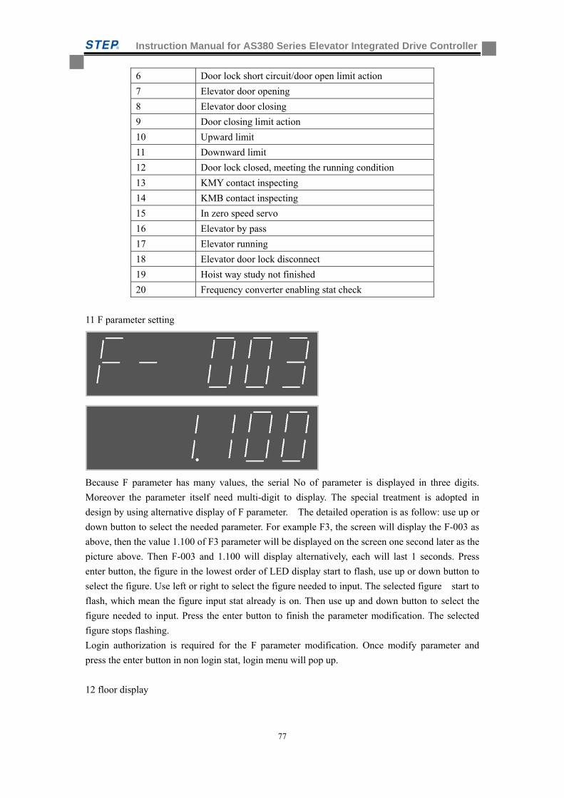
Instruction Manual for AS380 Series Elevator Integrated Drive Controller
77
6 Door lock short circuit/door open limit action
7 Elevator door opening
8 Elevator door closing
9 Door closing limit action
10 Upward limit
11 Downward limit
12 Door lock closed, meeting the running condition
13 KMY contact inspecting
14 KMB contact inspecting
15 In zero speed servo
16 Elevator by pass
17 Elevator running
18 Elevator door lock disconnect
19 Hoist way study not finished
20 Frequency converter enabling stat check
11 F parameter setting
Because F parameter has many values, the serial No of parameter is displayed in three digits.
Moreover the parameter itself need multi-digit to display. The special treatment is adopted in
design by using alternative display of F parameter. The detailed operation is as follow: use up or
down button to select the needed parameter. For example F3, the screen will display the F-003 as
above, then the value 1.100 of F3 parameter will be displayed on the screen one second later as the
picture above. Then F-003 and 1.100 will display alternatively, each will last 1 seconds. Press
enter button, the figure in the lowest order of LED display start to flash, use up or down button to
select the figure. Use left or right to select the figure needed to input. The selected figure start to
flash, which mean the figure input stat already is on. Then use up and down button to select the
figure needed to input. Press the enter button to finish the parameter modification. The selected
figure stops flashing.
Login authorization is required for the F parameter modification. Once modify parameter and
press the enter button in non login stat, login menu will pop up.
12 floor display
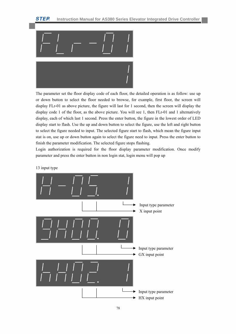
Instruction Manual for AS380 Series Elevator Integrated Drive Controller
78
The parameter set the floor display code of each floor, the detailed operation is as follow: use up
or down button to select the floor needed to browse, for example, first floor, the screen will
display FLr-01 as above picture, the figure will last for 1 second, then the screen will display the
display code 1 of the floor, as the above picture. You will see 1, then FLr-01 and 1 alternatively
display, each of which last 1 second. Press the enter button, the figure in the lowest order of LED
display start to flash. Use the up and down button to select the figure, use the left and right button
to select the figure needed to input. The selected figure start to flash, which mean the figure input
stat is on, use up or down button again to select the figure need to input. Press the enter button to
finish the parameter modification. The selected figure stops flashing.
Login authorization is required for the floor display parameter modification. Once modify
parameter and press the enter button in non login stat, login menu will pop up
13 input type
Input type parameter
X input point
Input type parameter
GX input point
Input type parameter
HX input point
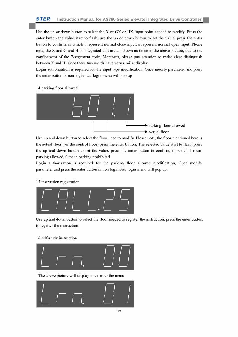
Instruction Manual for AS380 Series Elevator Integrated Drive Controller
79
Use the up or down button to select the X or GX or HX input point needed to modify. Press the
enter button the value start to flash, use the up or down button to set the value. press the enter
button to confirm, in which 1 represent normal close input, o represent normal open input. Please
note, the X and G and H of integrated unit are all shown as those in the above picture, due to the
confinement of the 7-segement code, Moreover, please pay attention to make clear distinguish
between X and H, since these two words have very similar display.
Login authorization is required for the input type modification. Once modify parameter and press
the enter button in non login stat, login menu will pop up
14 parking floor allowed
Parking floor allowed
Actual floor
Use up and down button to select the floor need to modify. Please note, the floor mentioned here is
the actual floor ( or the control floor) press the enter button. The selected value start to flash, press
the up and down button to set the value. press the enter button to confirm, in which 1 mean
parking allowed, 0 mean parking prohibited.
Login authorization is required for the parking floor allowed modification, Once modify
parameter and press the enter button in non login stat, login menu will pop up.
15 instruction registration
Use up and down button to select the floor needed to register the instruction, press the enter button,
to register the instruction.
16 self-study instruction
The above picture will display once enter the menu.
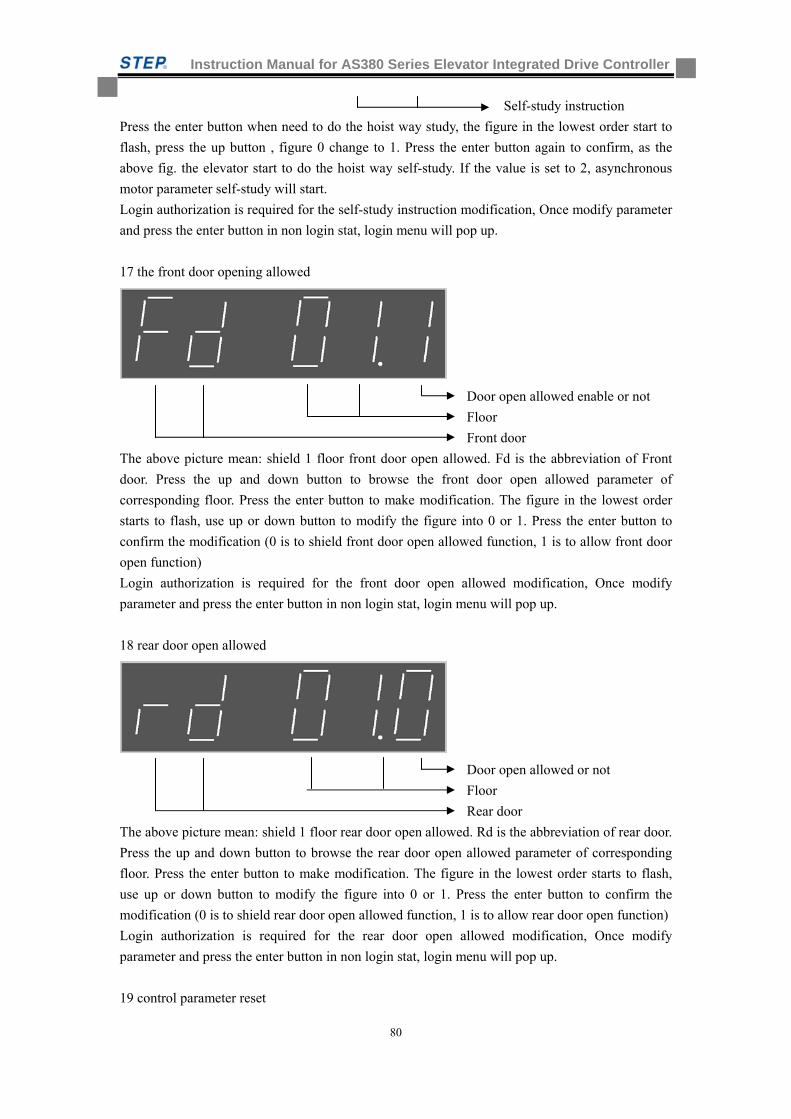
Instruction Manual for AS380 Series Elevator Integrated Drive Controller
80
Self-study instruction
Press the enter button when need to do the hoist way study, the figure in the lowest order start to
flash, press the up button , figure 0 change to 1. Press the enter button again to confirm, as the
above fig. the elevator start to do the hoist way self-study. If the value is set to 2, asynchronous
motor parameter self-study will start.
Login authorization is required for the self-study instruction modification, Once modify parameter
and press the enter button in non login stat, login menu will pop up.
17 the front door opening allowed
Door open allowed enable or not
Floor
Front door
The above picture mean: shield 1 floor front door open allowed. Fd is the abbreviation of Front
door. Press the up and down button to browse the front door open allowed parameter of
corresponding floor. Press the enter button to make modification. The figure in the lowest order
starts to flash, use up or down button to modify the figure into 0 or 1. Press the enter button to
confirm the modification (0 is to shield front door open allowed function, 1 is to allow front door
open function)
Login authorization is required for the front door open allowed modification, Once modify
parameter and press the enter button in non login stat, login menu will pop up.
18 rear door open allowed
Door open allowed or not
Floor
Rear door
The above picture mean: shield 1 floor rear door open allowed. Rd is the abbreviation of rear door.
Press the up and down button to browse the rear door open allowed parameter of corresponding
floor. Press the enter button to make modification. The figure in the lowest order starts to flash,
use up or down button to modify the figure into 0 or 1. Press the enter button to confirm the
modification (0 is to shield rear door open allowed function, 1 is to allow rear door open function)
Login authorization is required for the rear door open allowed modification, Once modify
parameter and press the enter button in non login stat, login menu will pop up.
19 control parameter reset
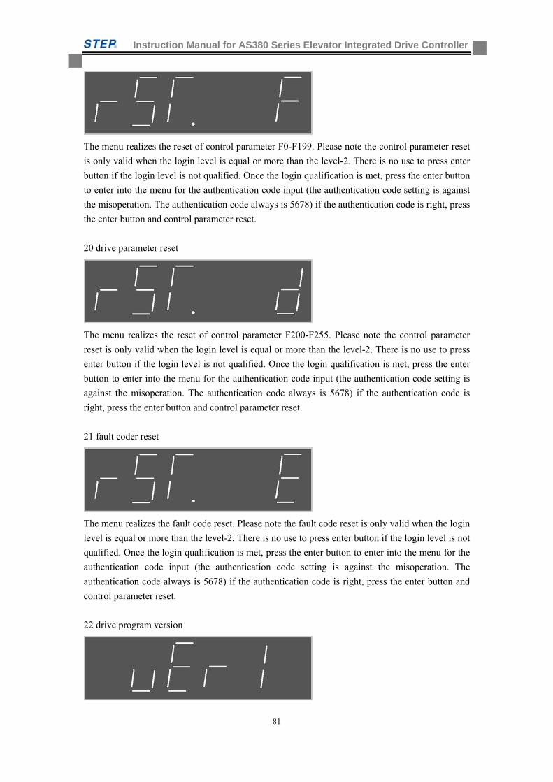
Instruction Manual for AS380 Series Elevator Integrated Drive Controller
81
The menu realizes the reset of control parameter F0-F199. Please note the control parameter reset
is only valid when the login level is equal or more than the level-2. There is no use to press enter
button if the login level is not qualified. Once the login qualification is met, press the enter button
to enter into the menu for the authentication code input (the authentication code setting is against
the misoperation. The authentication code always is 5678) if the authentication code is right, press
the enter button and control parameter reset.
20 drive parameter reset
The menu realizes the reset of control parameter F200-F255. Please note the control parameter
reset is only valid when the login level is equal or more than the level-2. There is no use to press
enter button if the login level is not qualified. Once the login qualification is met, press the enter
button to enter into the menu for the authentication code input (the authentication code setting is
against the misoperation. The authentication code always is 5678) if the authentication code is
right, press the enter button and control parameter reset.
21 fault coder reset
The menu realizes the fault code reset. Please note the fault code reset is only valid when the login
level is equal or more than the level-2. There is no use to press enter button if the login level is not
qualified. Once the login qualification is met, press the enter button to enter into the menu for the
authentication code input (the authentication code setting is against the misoperation. The
authentication code always is 5678) if the authentication code is right, press the enter button and
control parameter reset.
22 drive program version
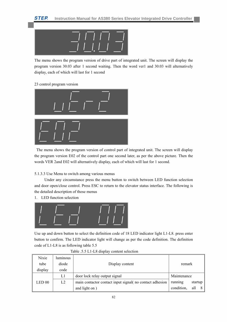
Instruction Manual for AS380 Series Elevator Integrated Drive Controller
82
The menu shows the program version of drive part of integrated unit. The screen will display the
program version 30.03 after 1 second waiting. Then the word ver1 and 30.03 will alternatively
display, each of which will last for 1 second
23 control program version
The menu shows the program version of control part of integrated unit. The screen will display
the program version E02 of the control part one second later, as per the above picture. Then the
words VER 2and E02 will alternatively display, each of which will last for 1 second.
5.1.3.3 Use Menu to switch among various menus
Under any circumstance press the menu button to switch between LED function selection
and door open/close control. Press ESC to return to the elevator status interface. The following is
the detailed description of those menus
1. LED function selection
Use up and down button to select the definition code of 18 LED indicator light L1-L8. press enter
button to confirm. The LED indicator light will change as per the code definition. The definition
code of L1-L8 is as following table 5.5
Table .5.5 L1-L8 display content selection
Nixie
tube
display
luminous
diode
code
Display content remark
LED 00
L1 door lock relay output signal Maintenance
running startup
condition, all 8
L2 main contactor contact input signal( no contact adhesion
and light on )
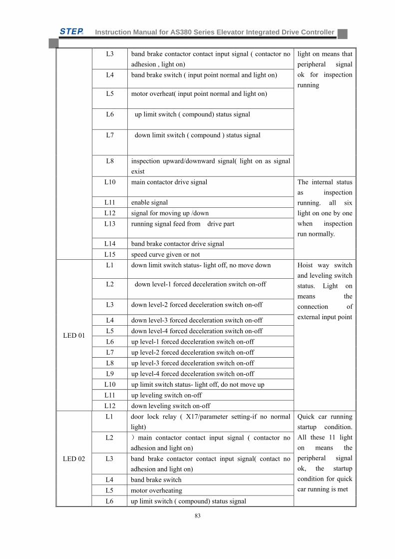
Instruction Manual for AS380 Series Elevator Integrated Drive Controller
83
L3 band brake contactor contact input signal ( contactor no
adhesion , light on)
light on means that
peripheral signal
ok for inspection
running
L4 band brake switch ( input point normal and light on)
L5 motor overheat( input point normal and light on)
L6 up limit switch ( compound) status signal
L7 down limit switch ( compound ) status signal
L8 inspection upward/downward signal( light on as signal
exist
L10 main contactor drive signal The internal status
as inspection
running. all six
light on one by one
when inspection
run normally.
L11 enable signal
L12 signal for moving up /down
L13 running signal feed from drive part
L14 band brake contactor drive signal
L15 speed curve given or not
LED 01
L1 down limit switch status- light off, no move down Hoist way switch
and leveling switch
status. Light on
means the
connection of
external input point
L2 down level-1 forced deceleration switch on-off
L3 down level-2 forced deceleration switch on-off
L4 down level-3 forced deceleration switch on-off
L5 down level-4 forced deceleration switch on-off
L6 up level-1 forced deceleration switch on-off
L7 up level-2 forced deceleration switch on-off
L8 up level-3 forced deceleration switch on-off
L9 up level-4 forced deceleration switch on-off
L10 up limit switch status- light off, do not move up
L11 up leveling switch on-off
L12 down leveling switch on-off
LED 02
L1 door lock relay ( X17/parameter setting-if no normal
light)
Quick car running
startup condition.
All these 11 light
on means the
peripheral signal
ok, the startup
condition for quick
car running is met
L2 )main contactor contact input signal ( contactor no
adhesion and light on)
L3 band brake contactor contact input signal( contact no
adhesion and light on)
L4 band brake switch
L5 motor overheating
L6 up limit switch ( compound) status signal
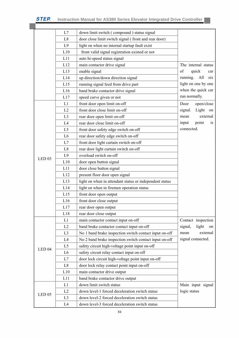
Instruction Manual for AS380 Series Elevator Integrated Drive Controller
84
L7 down limit switch ( compound ) status signal
L8 door close limit switch signal ( front and rear door)
L9 light on when no internal startup fault exist
L10 front valid signal registration existed or not
L11 auto hi-speed status signal
L12 main contactor drive signal The internal status
of quick car
running. All six
light on one by one
when the quick car
run normally.
L13 enable signal
L14 up direction/down direction signal
L15 running signal feed from drive part
L16 band brake contactor drive signal
L17 speed curve given or not
LED 03
L1 front door open limit on-off Door open/close
signal. Light on
mean external
input point is
connected.
L2 front door close limit on-off
L3 rear door open limit on-off
L4 rear door close limit on-off
L5 front door safety edge switch on-off
L6 rear door safety edge switch on-off
L7 front door light curtain switch on-off
L8 rear door light curtain switch on-off
L9 overload switch on-off
L10 door open button signal
L11 door close button signal
L12 present floor door open signal
L13 light on when in attendant status or independent status
L14 light on when in firemen operation status
L15 front door open output
L16 front door close output
L17 rear door open output
L18 rear door close output
LED 04
L1 main contactor contact input on-off Contact inspection
signal, light on
mean external
signal connected.
L2 band brake contactor contact input on-off
L3 No 1 band brake inspection switch contact input on-off
L4 No 2 band brake inspection switch contact input on-off
L5 safety circuit high-voltage point input on-off
L6 safety circuit relay contact input on-off
L7 door lock circuit high-voltage point input on-off
L8 door lock relay contact point input on-off
L10 main contactor drive output
L11 band brake contactor drive output
LED 05
L1 down limit switch status Main input signal
logic status L2 down level-1 forced deceleration switch status
L3 down level-2 forced deceleration switch status
L4 down level-3 forced deceleration switch status
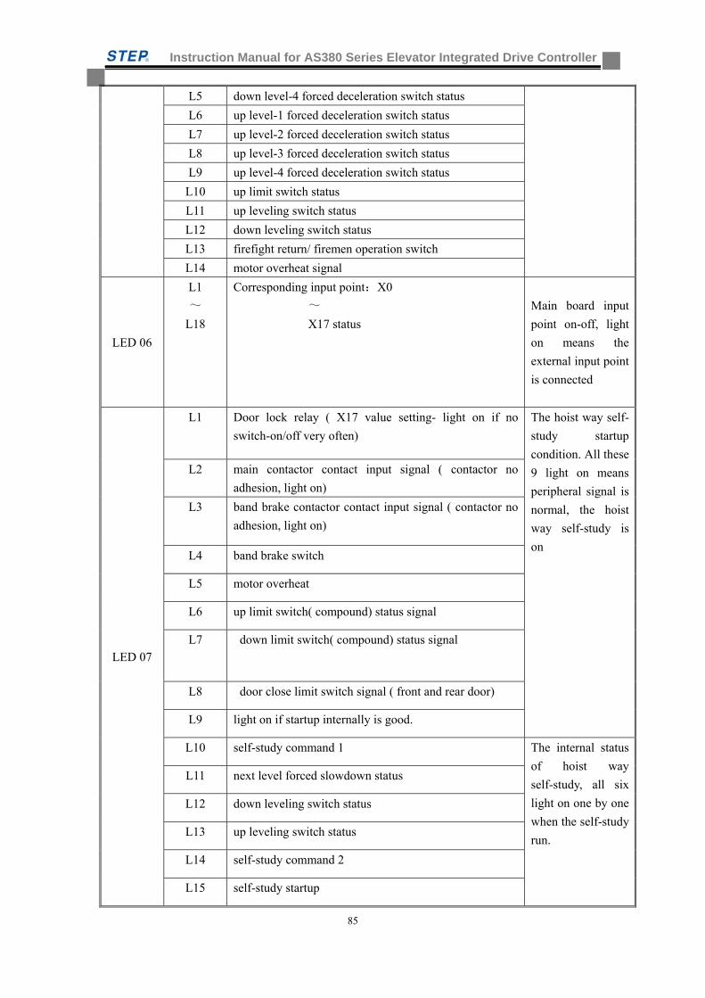
Instruction Manual for AS380 Series Elevator Integrated Drive Controller
85
L5 down level-4 forced deceleration switch status
L6 up level-1 forced deceleration switch status
L7 up level-2 forced deceleration switch status
L8 up level-3 forced deceleration switch status
L9 up level-4 forced deceleration switch status
L10 up limit switch status
L11 up leveling switch status
L12 down leveling switch status
L13 firefight return/ firemen operation switch
L14 motor overheat signal
LED 06
L1
~
L18
Corresponding input point:X0
~
X17 status
Main board input
point on-off, light
on means the
external input point
is connected
LED 07
L1 Door lock relay ( X17 value setting- light on if no
switch-on/off very often)
The hoist way self-
study startup
condition. All these
9 light on means
peripheral signal is
normal, the hoist
way self-study is
on
L2 main contactor contact input signal ( contactor no
adhesion, light on)
L3 band brake contactor contact input signal ( contactor no
adhesion, light on)
L4 band brake switch
L5 motor overheat
L6 up limit switch( compound) status signal
L7 down limit switch( compound) status signal
L8 door close limit switch signal ( front and rear door)
L9 light on if startup internally is good.
L10 self-study command 1 The internal status
of hoist way
self-study, all six
light on one by one
when the self-study
run.
L11 next level forced slowdown status
L12 down leveling switch status
L13 up leveling switch status
L14 self-study command 2
L15 self-study startup
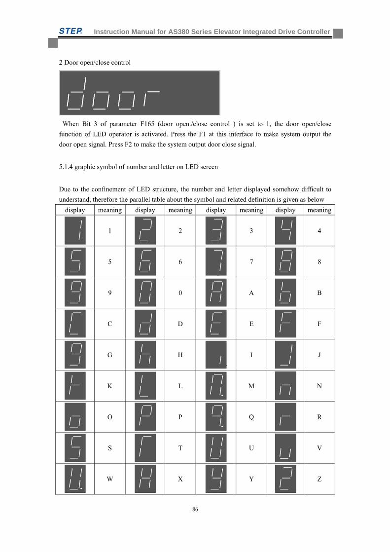
Instruction Manual for AS380 Series Elevator Integrated Drive Controller
86
2 Door open/close control
When Bit 3 of parameter F165 (door open./close control ) is set to 1, the door open/close
function of LED operator is activated. Press the F1 at this interface to make system output the
door open signal. Press F2 to make the system output door close signal.
5.1.4 graphic symbol of number and letter on LED screen
Due to the confinement of LED structure, the number and letter displayed somehow difficult to
understand, therefore the parallel table about the symbol and related definition is given as below
display meaning display meaning display meaning display meaning
1
2 3
4
5
6 7
8
9
0 A
B
C
D E
F
G
H I
J
K
L M
N
O
P Q
R
S
T U
V
W
X Y
Z
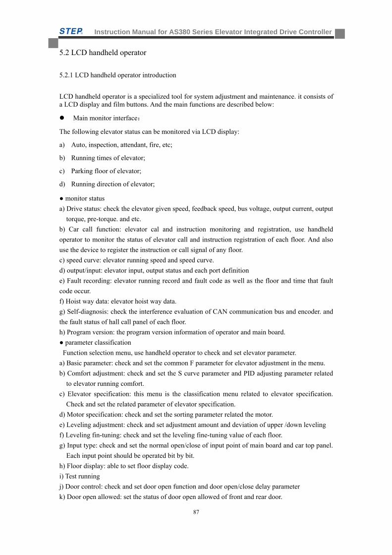
Instruction Manual for AS380 Series Elevator Integrated Drive Controller
87
5.2 LCD handheld operator
5.2.1 LCD handheld operator introduction
LCD handheld operator is a specialized tool for system adjustment and maintenance. it consists of a LCD display and film buttons. And the main functions are described below:
Main monitor interface:
The following elevator status can be monitored via LCD display:
a) Auto, inspection, attendant, fire, etc;
b) Running times of elevator;
c) Parking floor of elevator;
d) Running direction of elevator;
monitor status
a) Drive status: check the elevator given speed, feedback speed, bus voltage, output current, output
torque, pre-torque. and etc.
b) Car call function: elevator cal and instruction monitoring and registration, use handheld
operator to monitor the status of elevator call and instruction registration of each floor. And also
use the device to register the instruction or call signal of any floor.
c) speed curve: elevator running speed and speed curve.
d) output/input: elevator input, output status and each port definition
e) Fault recording: elevator running record and fault code as well as the floor and time that fault
code occur.
f) Hoist way data: elevator hoist way data.
g) Self-diagnosis: check the interference evaluation of CAN communication bus and encoder. and
the fault status of hall call panel of each floor.
h) Program version: the program version information of operator and main board.
parameter classification
Function selection menu, use handheld operator to check and set elevator parameter.
a) Basic parameter: check and set the common F parameter for elevator adjustment in the menu.
b) Comfort adjustment: check and set the S curve parameter and PID adjusting parameter related
to elevator running comfort.
c) Elevator specification: this menu is the classification menu related to elevator specification.
Check and set the related parameter of elevator specification.
d) Motor specification: check and set the sorting parameter related the motor.
e) Leveling adjustment: check and set adjustment amount and deviation of upper /down leveling
f) Leveling fin-tuning: check and set the leveling fine-tuning value of each floor.
g) Input type: check and set the normal open/close of input point of main board and car top panel.
Each input point should be operated bit by bit.
h) Floor display: able to set floor display code.
i) Test running
j) Door control: check and set door open function and door open/close delay parameter
k) Door open allowed: set the status of door open allowed of front and rear door.
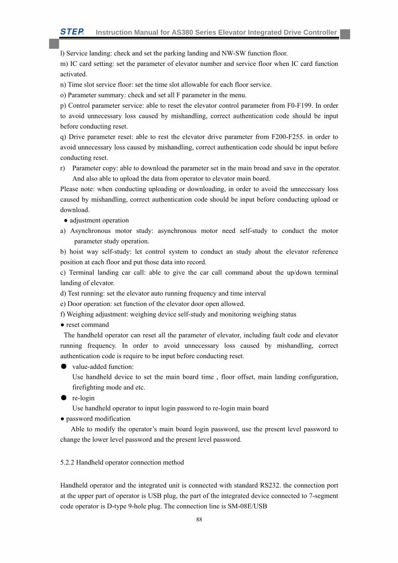
Instruction Manual for AS380 Series Elevator Integrated Drive Controller
88
l) Service landing: check and set the parking landing and NW-SW function floor.
m) IC card setting: set the parameter of elevator number and service floor when IC card function
activated.
n) Time slot service floor: set the time slot allowable for each floor service.
o) Parameter summary: check and set all F parameter in the menu.
p) Control parameter service: able to reset the elevator control parameter from F0-F199. In order
to avoid unnecessary loss caused by mishandling, correct authentication code should be input
before conducting reset.
q) Drive parameter reset: able to rest the elevator drive parameter from F200-F255. in order to
avoid unnecessary loss caused by mishandling, correct authentication code should be input before
conducting reset.
r) Parameter copy: able to download the parameter set in the main broad and save in the operator.
And also able to upload the data from operator to elevator main board.
Please note: when conducting uploading or downloading, in order to avoid the unnecessary loss
caused by mishandling, correct authentication code should be input before conducting upload or
download.
adjustment operation
a) Asynchronous motor study: asynchronous motor need self-study to conduct the motor
parameter study operation.
b) hoist way self-study: let control system to conduct an study about the elevator reference
position at each floor and put those data into record.
c) Terminal landing car call: able to give the car call command about the up/down terminal
landing of elevator.
d) Test running: set the elevator auto running frequency and time interval
e) Door operation: set function of the elevator door open allowed.
f) Weighing adjustment: weighing device self-study and monitoring weighing status
reset command
The handheld operator can reset all the parameter of elevator, including fault code and elevator
running frequency. In order to avoid unnecessary loss caused by mishandling, correct
authentication code is require to be input before conducting reset.
value-added function:
Use handheld device to set the main board time , floor offset, main landing configuration,
firefighting mode and etc.
re-login
Use handheld operator to input login password to re-login main board
password modification
Able to modify the operator’s main board login password, use the present level password to
change the lower level password and the present level password.
5.2.2 Handheld operator connection method
Handheld operator and the integrated unit is connected with standard RS232. the connection port
at the upper part of operator is USB plug, the part of the integrated device connected to 7-segment
code operator is D-type 9-hole plug. The connection line is SM-08E/USB
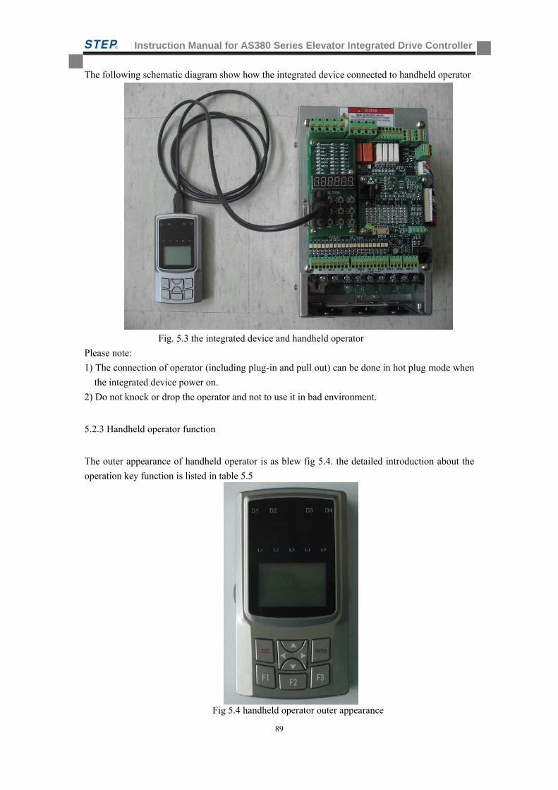
Instruction Manual for AS380 Series Elevator Integrated Drive Controller
89
The following schematic diagram show how the integrated device connected to handheld operator
Fig. 5.3 the integrated device and handheld operator
Please note:
1) The connection of operator (including plug-in and pull out) can be done in hot plug mode when
the integrated device power on.
2) Do not knock or drop the operator and not to use it in bad environment.
5.2.3 Handheld operator function
The outer appearance of handheld operator is as blew fig 5.4. the detailed introduction about the
operation key function is listed in table 5.5
Fig 5.4 handheld operator outer appearance
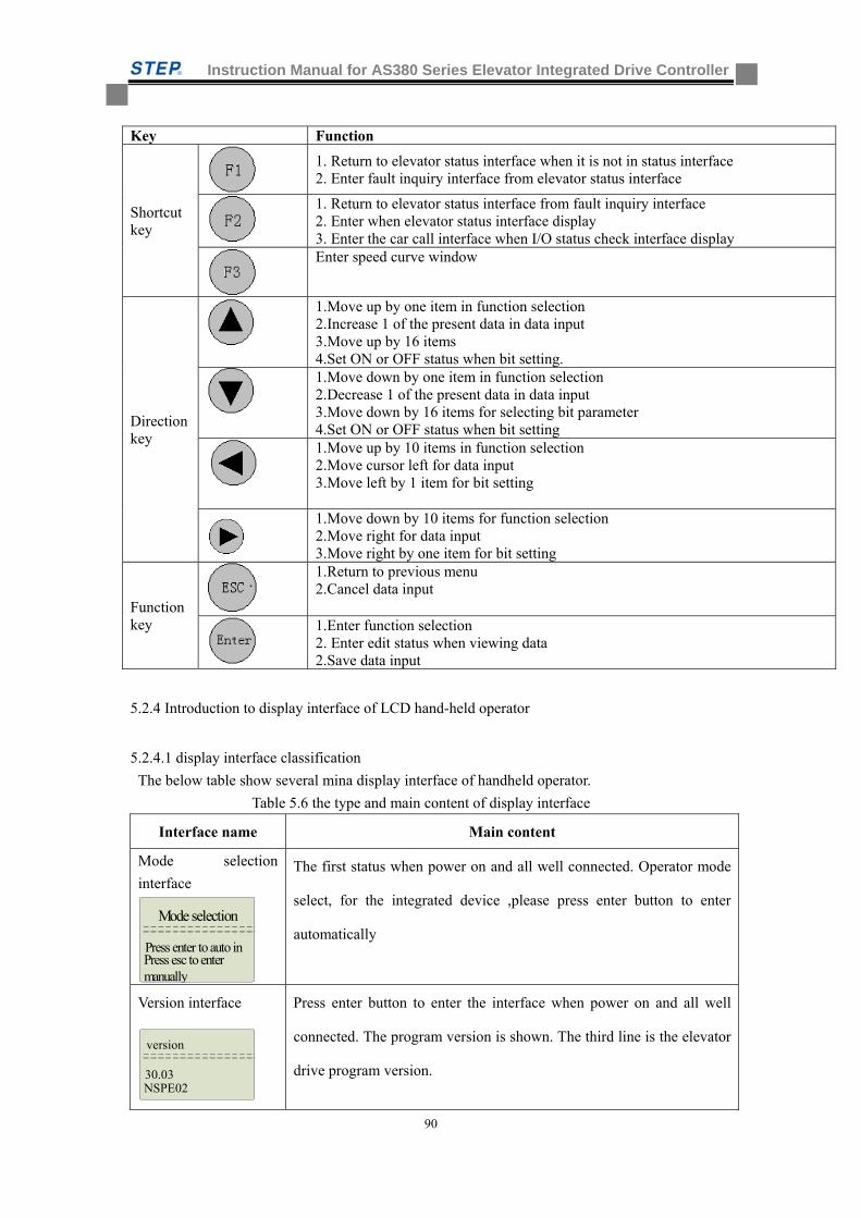
Instruction Manual for AS380 Series Elevator Integrated Drive Controller
90
Key Function
Shortcut key
1. Return to elevator status interface when it is not in status interface 2. Enter fault inquiry interface from elevator status interface
1. Return to elevator status interface from fault inquiry interface 2. Enter when elevator status interface display 3. Enter the car call interface when I/O status check interface display Enter speed curve window
Direction key
1.Move up by one item in function selection 2.Increase 1 of the present data in data input 3.Move up by 16 items 4.Set ON or OFF status when bit setting.
1.Move down by one item in function selection 2.Decrease 1 of the present data in data input 3.Move down by 16 items for selecting bit parameter 4.Set ON or OFF status when bit setting
1.Move up by 10 items in function selection 2.Move cursor left for data input 3.Move left by 1 item for bit setting
1.Move down by 10 items for function selection 2.Move right for data input 3.Move right by one item for bit setting
Function key
1.Return to previous menu 2.Cancel data input
1.Enter function selection 2. Enter edit status when viewing data 2.Save data input
5.2.4 Introduction to display interface of LCD hand-held operator
5.2.4.1 display interface classification
The below table show several mina display interface of handheld operator.
Table 5.6 the type and main content of display interface
Interface name Main content
Mode selection
interface
Mode selection
Press esc to enter manually
Press enter to auto in
The first status when power on and all well connected. Operator mode
select, for the integrated device ,please press enter button to enter
automatically
Version interface
version
NSPE02
30.03
Press enter button to enter the interface when power on and all well
connected. The program version is shown. The third line is the elevator
drive program version.
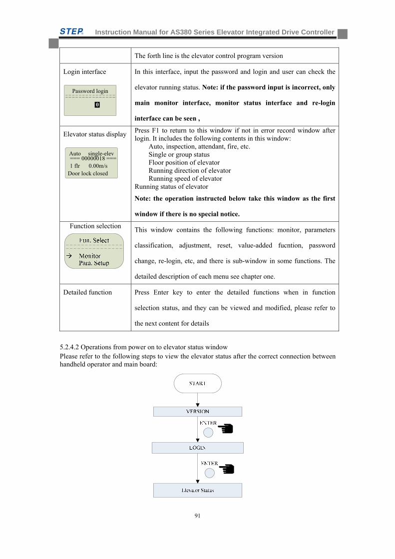
Instruction Manual for AS380 Series Elevator Integrated Drive Controller
91
The forth line is the elevator control program version
Login interface
Password login
0
In this interface, input the password and login and user can check the
elevator running status. Note: if the password input is incorrect, only
main monitor interface, monitor status interface and re-login
interface can be seen ,
Elevator status display
Auto single-elev
Door lock closed 1 flr 0.00m/s
=== 00000018 ===
Press F1 to return to this window if not in error record window after login. It includes the following contents in this window: Auto, inspection, attendant, fire, etc. Single or group status Floor position of elevator Running direction of elevator Running speed of elevator Running status of elevator
Note: the operation instructed below take this window as the first
window if there is no special notice.
Function selection
This window contains the following functions: monitor, parameters
classification, adjustment, reset, value-added fucntion, password
change, re-login, etc, and there is sub-window in some functions. The
detailed description of each menu see chapter one.
Detailed function Press Enter key to enter the detailed functions when in function
selection status, and they can be viewed and modified, please refer to
the next content for details
5.2.4.2 Operations from power on to elevator status window Please refer to the following steps to view the elevator status after the correct connection between handheld operator and main board:
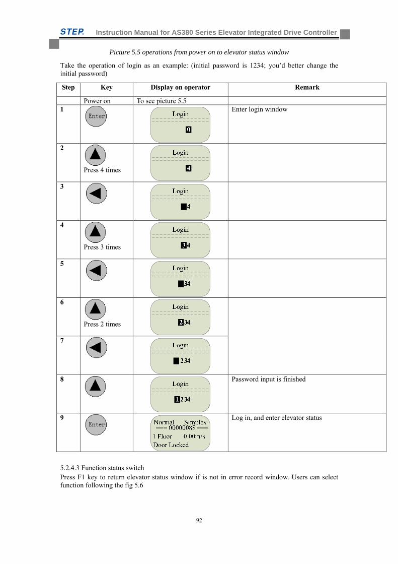
Instruction Manual for AS380 Series Elevator Integrated Drive Controller
92
Picture 5.5 operations from power on to elevator status window
Take the operation of login as an example: (initial password is 1234; you’d better change the initial password)
Step Key Display on operator Remark
Power on To see picture 5.5 1
Enter login window
2
Press 4 times
3
4
Press 3 times
5
6
Press 2 times
7
8
Password input is finished
9
Log in, and enter elevator status
5.2.4.3 Function status switch Press F1 key to return elevator status window if is not in error record window. Users can select function following the fig 5.6
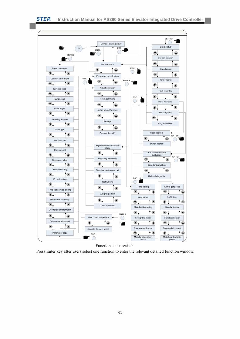
Instruction Manual for AS380 Series Elevator Integrated Drive Controller
93
ENTER
ENTER
ESC
ENTER
ESC
ESC
ESC
F1ENTER
ESC
Adjust operation
Parameter classifciation
Reset command
Value-added function
Basic parameter
Comfort adjustment
Elevator spec
Motor spec
Level adjust
Leveling fin-tune
Input type
Floor display
Door control
Door open allow
Service landing
IC card setting
Time slot service landing
Parameter summary
Control parameter reset
Parameter copy
Drive parameter reset
Drive status
Car call fucntion
Speed curve
Input /output
Fault recording
Hoist way data
Self-diagnosis
Program version
Floor position
Switch positon
Bus communication evaluation
Encoder evaluation
Hall call diagnosis
Main board to operator
Operator to main board
Asynchronous motor self-study
Hoist way self-study
Terminal landing car call
Test running
Door operation
Weighing adjust
ENTER
ENTER
ENTER
ESC
Time setting
Main landing settng
Firefighting mode
Group control mode
Main landing return delay
Arrival gong lead
Light time
Attendant mode
Call classification
Double-click cancel
Main board validity period
Floor offset
Monitor status
Re-login
Password modify
Elevator status display
Function status switch Press Enter key after users select one function to enter the relevant detailed function window.
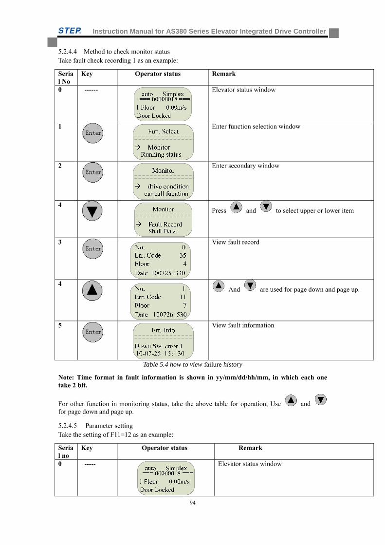
Instruction Manual for AS380 Series Elevator Integrated Drive Controller
94
5.2.4.4 Method to check monitor status Take fault check recording 1 as an example:
Serial No
Key Operator status Remark
0 ------ Elevator status window
1
Enter function selection window
2
Enter secondary window
4
Press and to select upper or lower item
3
View fault record
4
And are used for page down and page up.
5
View fault information
Table 5.4 how to view failure history
Note: Time format in fault information is shown in yy/mm/dd/hh/mm, in which each one take 2 bit.
For other function in monitoring status, take the above table for operation, Use and for page down and page up.
5.2.4.5 Parameter setting Take the setting of F11=12 as an example:
Serial no
Key Operator status Remark
0 ----- Elevator status window
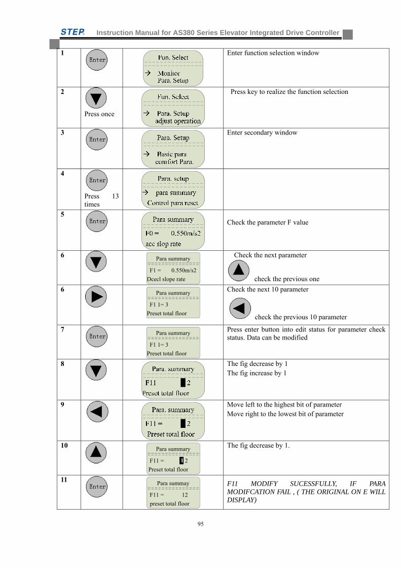
Instruction Manual for AS380 Series Elevator Integrated Drive Controller
95
1
Enter function selection window
2
Press once
Press key to realize the function selection
3
Enter secondary window
4
Press 13 times
5
Check the parameter F value
6
Para summary
Dcecl slope rate
F1 = 0.550m/s2
Check the next parameter
check the previous one
6
Para summary
Preset total floor
F1 1= 3
Check the next 10 parameter
check the previous 10 parameter
7
Para summary
Preset total floor
F1 1= 3
Press enter button into edit status for parameter check status. Data can be modified
8
The fig decrease by 1 The fig increase by 1
9
Move left to the highest bit of parameter Move right to the lowest bit of parameter
10
Para summary
Preset total floor
F11 = 21
The fig decrease by 1.
11
Para summay
preset total floor
F11 = 12
F11 MODIFY SUCESSFULLY, IF PARA MODIFCATION FAIL , ( THE ORIGINAL ON E WILL DISPLAY)
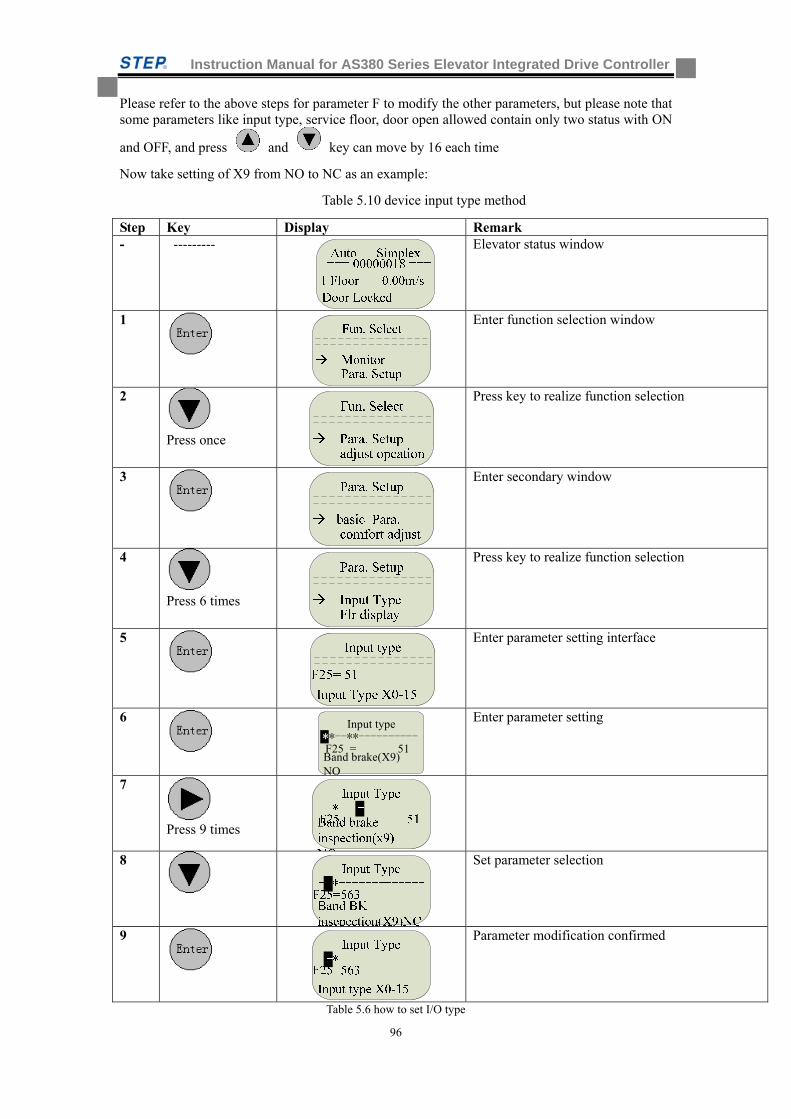
Instruction Manual for AS380 Series Elevator Integrated Drive Controller
96
Please refer to the above steps for parameter F to modify the other parameters, but please note that some parameters like input type, service floor, door open allowed contain only two status with ON
and OFF, and press and key can move by 16 each time
Now take setting of X9 from NO to NC as an example:
Table 5.10 device input type method
Step Key Display Remark - --------- Elevator status window
1
Enter function selection window
2
Press once
Press key to realize function selection
3
Enter secondary window
4
Press 6 times
Press key to realize function selection
5
Enter parameter setting interface
6
Input type
Band brake(X9) NO
F25 = 51**--**----------*
Enter parameter setting
7
Press 9 times
8
Set parameter selection
9
Parameter modification confirmed
Table 5.6 how to set I/O type
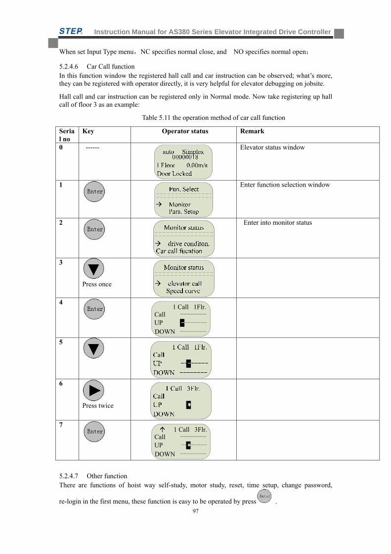
Instruction Manual for AS380 Series Elevator Integrated Drive Controller
97
When set Input Type menu,NC specifies normal close, and NO specifies normal open;
5.2.4.6 Car Call function In this function window the registered hall call and car instruction can be observed; what’s more, they can be registered with operator directly, it is very helpful for elevator debugging on jobsite.
Hall call and car instruction can be registered only in Normal mode. Now take registering up hall call of floor 3 as an example:
Table 5.11 the operation method of car call function
Serial no
Key Operator status Remark
0 ------ Elevator status window
1
Enter function selection window
2
Enter into monitor status
3
Press once
4
1 Call 1Flr.
DOWN --------
Call --------UP --------
5
6
Press twice
7
1 Call 3Flr.
DOWN --------
Call --------UP --------
5.2.4.7 Other function There are functions of hoist way self-study, motor study, reset, time setup, change password,
re-login in the first menu, these function is easy to be operated by press .
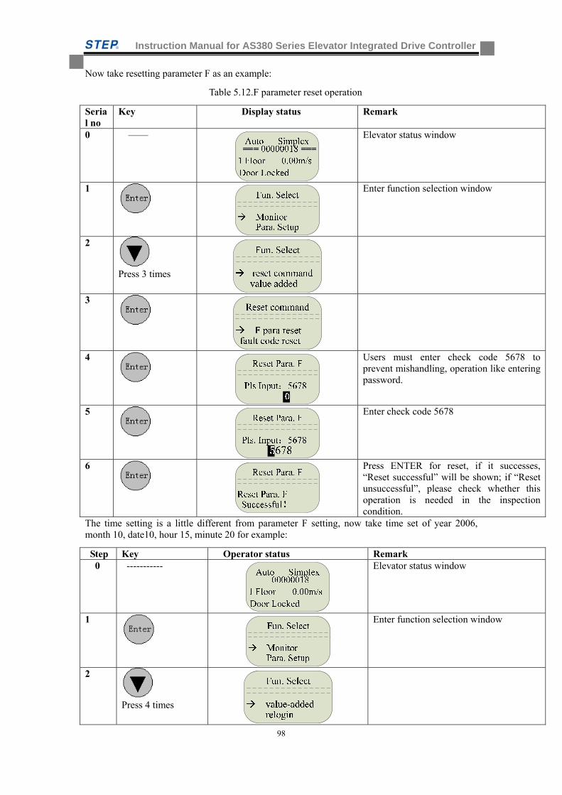
Instruction Manual for AS380 Series Elevator Integrated Drive Controller
98
Now take resetting parameter F as an example:
Table 5.12.F parameter reset operation
Serial no
Key Display status Remark
0 —— Elevator status window
1
Enter function selection window
2
Press 3 times
3
4
Users must enter check code 5678 to prevent mishandling, operation like entering password.
5
Enter check code 5678
6
Press ENTER for reset, if it successes, “Reset successful” will be shown; if “Reset unsuccessful”, please check whether this operation is needed in the inspection condition.
The time setting is a little different from parameter F setting, now take time set of year 2006, month 10, date10, hour 15, minute 20 for example:
Step Key Operator status Remark 0 ----------- Elevator status window
1
Enter function selection window
2
Press 4 times
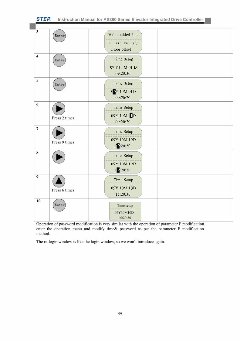
Instruction Manual for AS380 Series Elevator Integrated Drive Controller
99
3
4
5
6
Press 2 times
7
Press 9 times
8
9
Press 6 times
10
Time setup
15:20:30
09Y10M10D
Operation of password modification is very similar with the operation of parameter F modification. enter the operation menu and modify time& password as per the parameter F modification method.
The re-login window is like the login window, so we won’t introduce again.
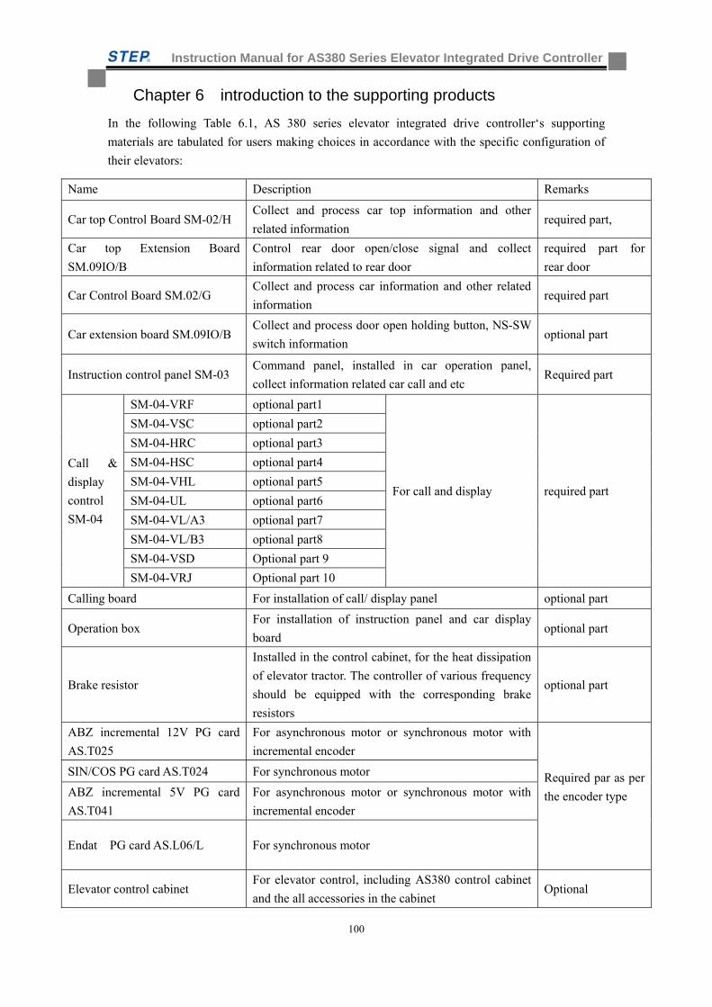
Instruction Manual for AS380 Series Elevator Integrated Drive Controller
100
Chapter 6 introduction to the supporting products
In the following Table 6.1, AS 380 series elevator integrated drive controller‘s supporting
materials are tabulated for users making choices in accordance with the specific configuration of
their elevators:
Name Description Remarks
Car top Control Board SM-02/H Collect and process car top information and other
related information required part,
Car top Extension Board
SM.09IO/B
Control rear door open/close signal and collect
information related to rear door
required part for
rear door
Car Control Board SM.02/G Collect and process car information and other related
information required part
Car extension board SM.09IO/B Collect and process door open holding button, NS-SW
switch information optional part
Instruction control panel SM-03 Command panel, installed in car operation panel,
collect information related car call and etc Required part
Call &
display
control
SM-04
SM-04-VRF optional part1
For call and display required part
SM-04-VSC optional part2
SM-04-HRC optional part3
SM-04-HSC optional part4
SM-04-VHL optional part5
SM-04-UL optional part6
SM-04-VL/A3 optional part7
SM-04-VL/B3 optional part8
SM-04-VSD Optional part 9
SM-04-VRJ Optional part 10
Calling board For installation of call/ display panel optional part
Operation box For installation of instruction panel and car display
board optional part
Brake resistor
Installed in the control cabinet, for the heat dissipation
of elevator tractor. The controller of various frequency
should be equipped with the corresponding brake
resistors
optional part
ABZ incremental 12V PG card
AS.T025
For asynchronous motor or synchronous motor with
incremental encoder
Required par as per
the encoder type
SIN/COS PG card AS.T024 For synchronous motor
ABZ incremental 5V PG card
AS.T041
For asynchronous motor or synchronous motor with
incremental encoder
Endat PG card AS.L06/L For synchronous motor
Elevator control cabinet For elevator control, including AS380 control cabinet
and the all accessories in the cabinet Optional
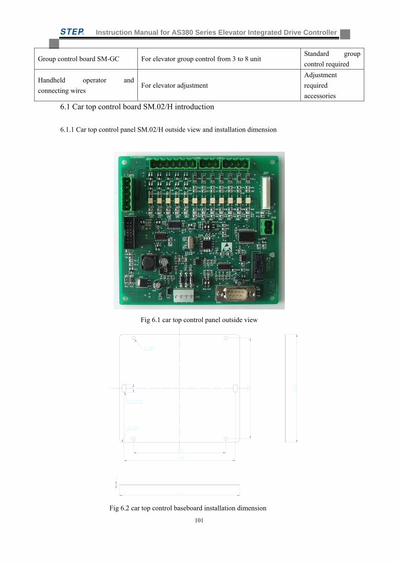
Instruction Manual for AS380 Series Elevator Integrated Drive Controller
101
Group control board SM-GC For elevator group control from 3 to 8 unit Standard group
control required
Handheld operator and
connecting wires For elevator adjustment
Adjustment
required
accessories
6.1 Car top control board SM.02/H introduction
6.1.1 Car top control panel SM.02/H outside view and installation dimension
Fig 6.1 car top control panel outside view
Fig 6.2 car top control baseboard installation dimension
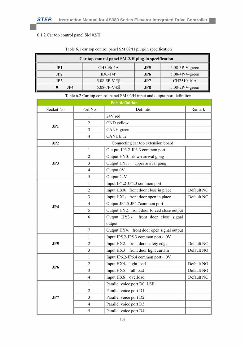
Instruction Manual for AS380 Series Elevator Integrated Drive Controller
102
6.1.2 Car top control panel SM 02/H
Table 6.1 car top control panel SM.02/H plug-in specification
Table 6.2 Car top control panel SM.02/H input and output port definition
Port definition
Socket No Port No Definition Remark
JP1
1 24V red
2 GND yellow
3 CANH green
4 CANL blue
JP2 Connecting car top extension board
JP3
1 Out put JP3.2-JP3.3 common port
2 Output HY0,down arrival gong
3 Output HY1, upper arrival gong
4 Output 0V
5 Output 24V
JP4
1 Input JP4.2-JP4.3 common port
2 Input HX0,front door close in place Default NC
3 Input HX1,front door open in place Default NC
4 Output JP4.5-JP4.7common port
5 Output HY2,front door forced close output
6 Output HY3, front door close signal
output
7 Output HY4, front door open signal output
JP5
1 Input JP5.2-JP5.3 common port,0V
2 Input HX2,front door safety edge Default NC
3 Input HX3,front door light curtain Default NO
JP6
1 Input JP6.2-JP6.4 common port,0V
2 Input HX4,light load Default NO
3 Input HX5,full load Default NO
4 Input HX6,overload Default NC
JP7
1 Parallel voice port D0, LSB
2 Parallel voice port D1
3 Parallel voice port D2
4 Parallel voice port D3
5 Parallel voice port D4
Car top control panel SM-2/H plug-in specification
插座号 型号 插座号 型号JP1 CH3.96-4A JP5 5.08-3P-V-green
JP2 IDC-14P JP6 5.08-4P-V-green
JP3 5.08-5P-V-绿 JP7 CH2510-10A
JP4 5.08-7P-V-绿 JP8 5.08-2P-V-green
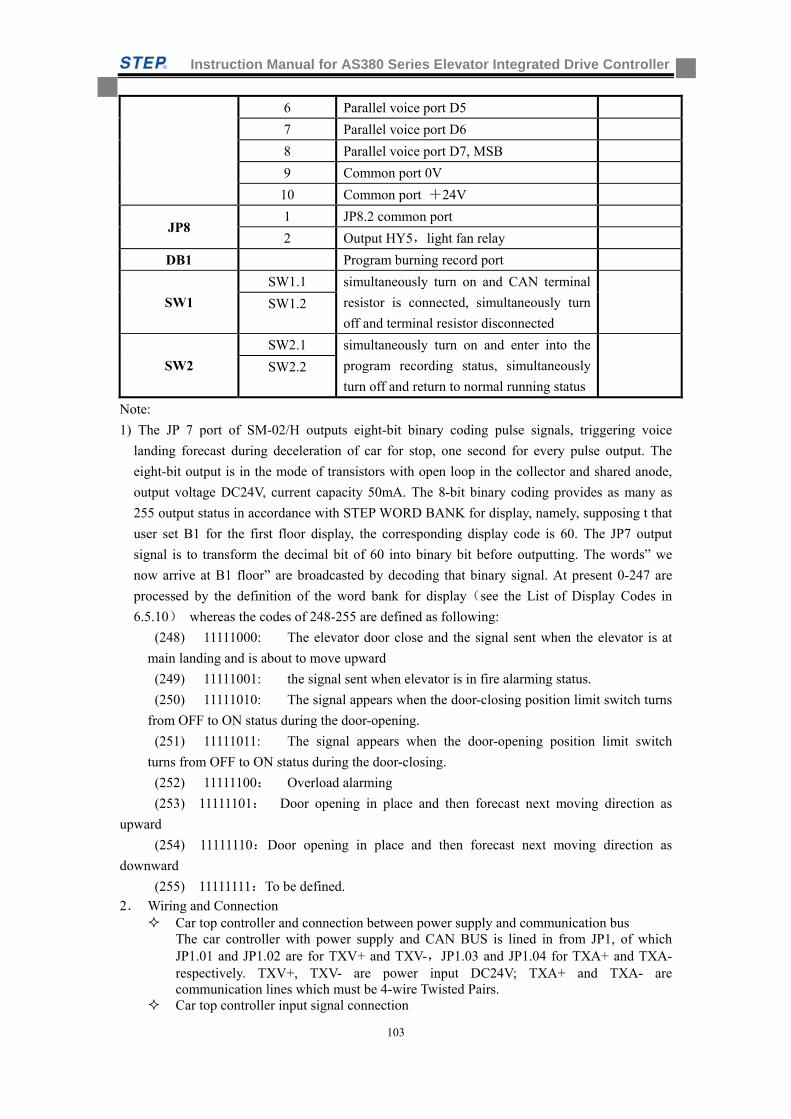
Instruction Manual for AS380 Series Elevator Integrated Drive Controller
103
6 Parallel voice port D5
7 Parallel voice port D6
8 Parallel voice port D7, MSB
9 Common port 0V
10 Common port +24V
JP8 1 JP8.2 common port
2 Output HY5,light fan relay
DB1 Program burning record port
SW1
SW1.1 simultaneously turn on and CAN terminal
resistor is connected, simultaneously turn
off and terminal resistor disconnected
SW1.2
SW2
SW2.1 simultaneously turn on and enter into the
program recording status, simultaneously
turn off and return to normal running status
SW2.2
Note:
1) The JP 7 port of SM-02/H outputs eight-bit binary coding pulse signals, triggering voice
landing forecast during deceleration of car for stop, one second for every pulse output. The
eight-bit output is in the mode of transistors with open loop in the collector and shared anode,
output voltage DC24V, current capacity 50mA. The 8-bit binary coding provides as many as
255 output status in accordance with STEP WORD BANK for display, namely, supposing t that
user set B1 for the first floor display, the corresponding display code is 60. The JP7 output
signal is to transform the decimal bit of 60 into binary bit before outputting. The words” we
now arrive at B1 floor” are broadcasted by decoding that binary signal. At present 0-247 are
processed by the definition of the word bank for display(see the List of Display Codes in
6.5.10) whereas the codes of 248-255 are defined as following:
(248) 11111000: The elevator door close and the signal sent when the elevator is at
main landing and is about to move upward
(249) 11111001: the signal sent when elevator is in fire alarming status.
(250) 11111010: The signal appears when the door-closing position limit switch turns
from OFF to ON status during the door-opening.
(251) 11111011: The signal appears when the door-opening position limit switch
turns from OFF to ON status during the door-closing.
(252) 11111100: Overload alarming
(253) 11111101: Door opening in place and then forecast next moving direction as
upward
(254) 11111110:Door opening in place and then forecast next moving direction as
downward
(255) 11111111:To be defined.
2. Wiring and Connection Car top controller and connection between power supply and communication bus
The car controller with power supply and CAN BUS is lined in from JP1, of which JP1.01 and JP1.02 are for TXV+ and TXV-,JP1.03 and JP1.04 for TXA+ and TXA- respectively. TXV+, TXV- are power input DC24V; TXA+ and TXA- are communication lines which must be 4-wire Twisted Pairs.
Car top controller input signal connection
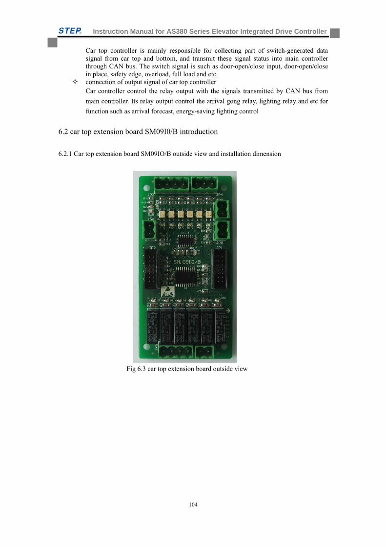
Instruction Manual for AS380 Series Elevator Integrated Drive Controller
104
Car top controller is mainly responsible for collecting part of switch-generated data signal from car top and bottom, and transmit these signal status into main controller through CAN bus. The switch signal is such as door-open/close input, door-open/close in place, safety edge, overload, full load and etc.
connection of output signal of car top controller Car controller control the relay output with the signals transmitted by CAN bus from
main controller. Its relay output control the arrival gong relay, lighting relay and etc for
function such as arrival forecast, energy-saving lighting control
6.2 car top extension board SM09I0/B introduction
6.2.1 Car top extension board SM09IO/B outside view and installation dimension
Fig 6.3 car top extension board outside view
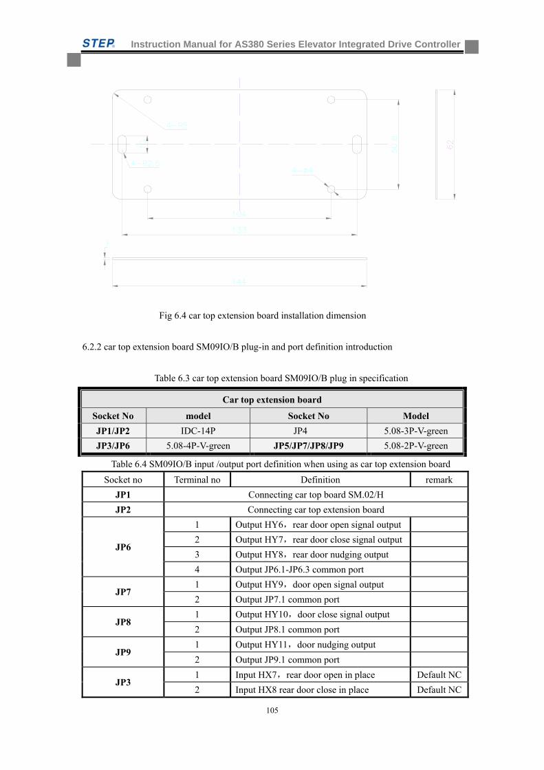
Instruction Manual for AS380 Series Elevator Integrated Drive Controller
105
Fig 6.4 car top extension board installation dimension
6.2.2 car top extension board SM09IO/B plug-in and port definition introduction
Table 6.3 car top extension board SM09IO/B plug in specification
Table 6.4 SM09IO/B input /output port definition when using as car top extension board
Socket no Terminal no Definition remark
JP1 Connecting car top board SM.02/H
JP2 Connecting car top extension board
JP6
1 Output HY6,rear door open signal output
2 Output HY7,rear door close signal output
3 Output HY8,rear door nudging output
4 Output JP6.1-JP6.3 common port
JP7 1 Output HY9,door open signal output
2 Output JP7.1 common port
JP8 1 Output HY10,door close signal output
2 Output JP8.1 common port
JP9 1 Output HY11,door nudging output
2 Output JP9.1 common port
JP3 1 Input HX7,rear door open in place Default NC
2 Input HX8 rear door close in place Default NC
Car top extension board
Socket No model Socket No Model
JP1/JP2 IDC-14P JP4 5.08-3P-V-green
JP3/JP6 5.08-4P-V-green JP5/JP7/JP8/JP9 5.08-2P-V-green
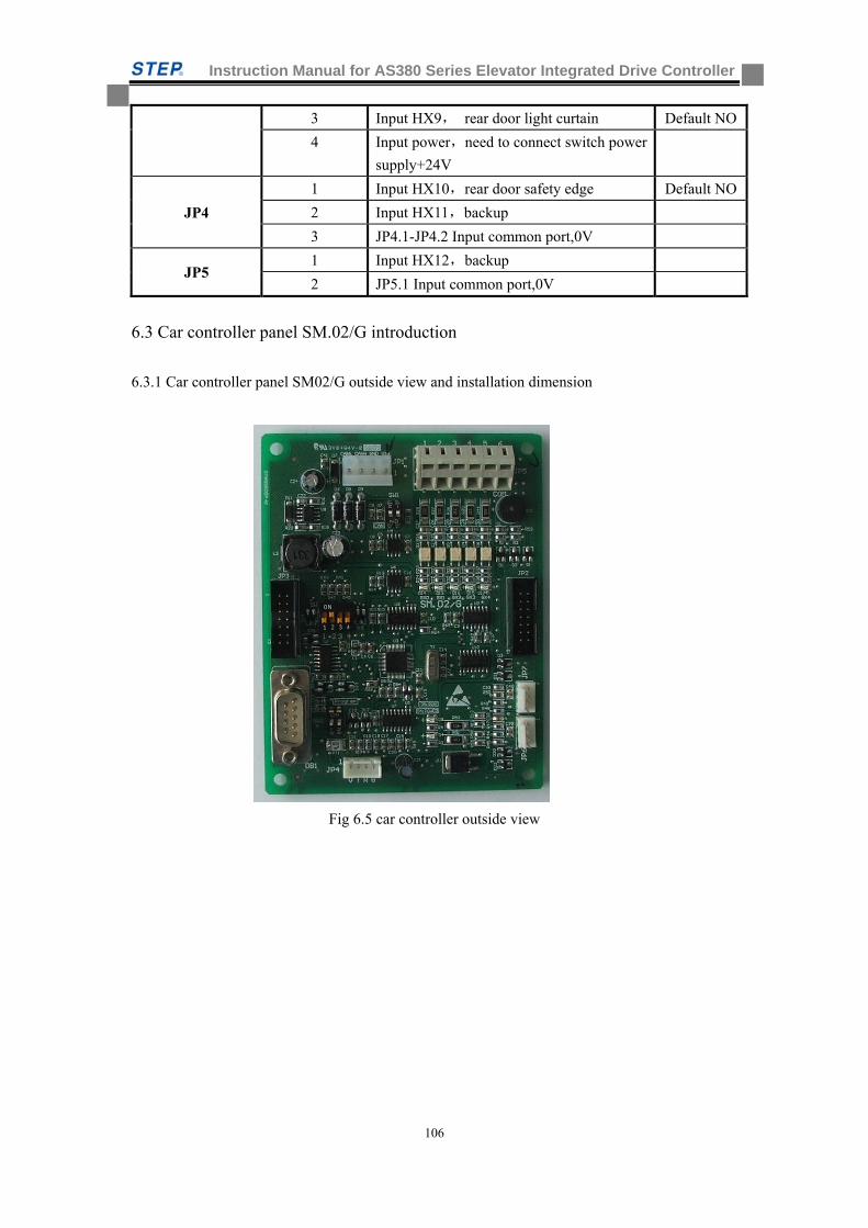
Instruction Manual for AS380 Series Elevator Integrated Drive Controller
106
3 Input HX9, rear door light curtain Default NO
4 Input power,need to connect switch power
supply+24V
JP4
1 Input HX10,rear door safety edge Default NO
2 Input HX11,backup
3 JP4.1-JP4.2 Input common port,0V
JP5 1 Input HX12,backup
2 JP5.1 Input common port,0V
6.3 Car controller panel SM.02/G introduction
6.3.1 Car controller panel SM02/G outside view and installation dimension
Fig 6.5 car controller outside view
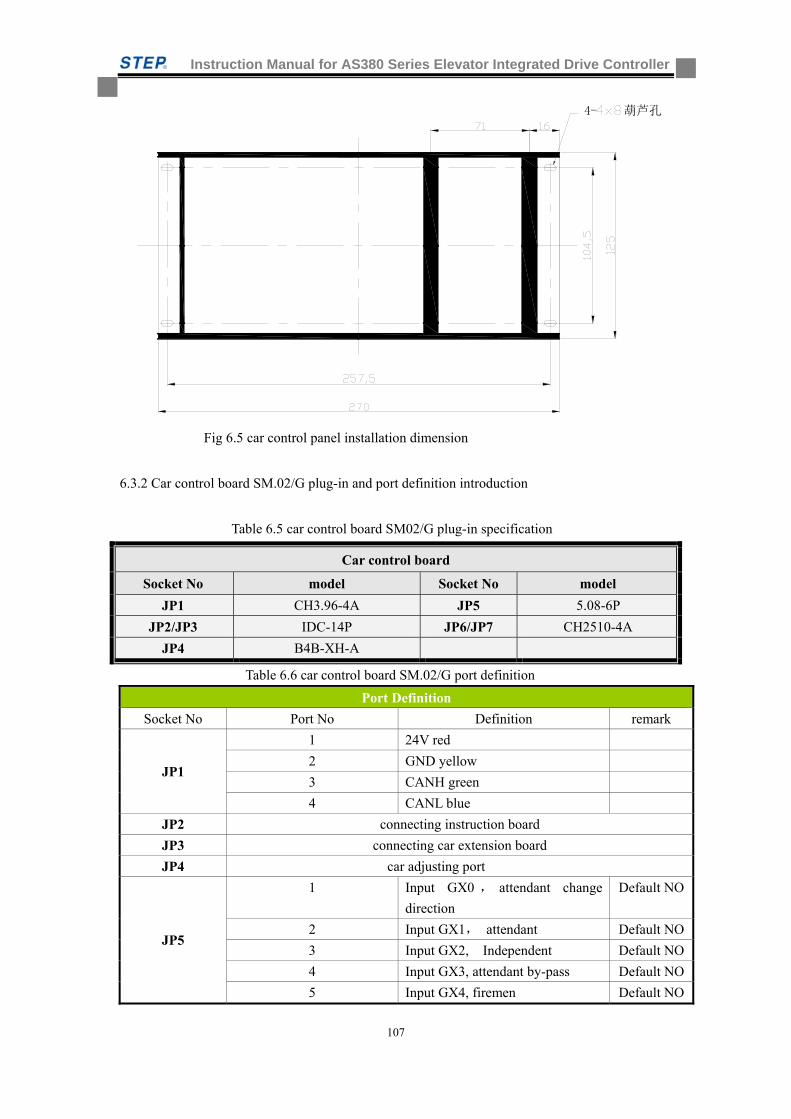
Instruction Manual for AS380 Series Elevator Integrated Drive Controller
107
4- 葫芦孔
Fig 6.5 car control panel installation dimension
6.3.2 Car control board SM.02/G plug-in and port definition introduction
Table 6.5 car control board SM02/G plug-in specification
Table 6.6 car control board SM.02/G port definition
Port Definition
Socket No Port No Definition remark
JP1
1 24V red
2 GND yellow
3 CANH green
4 CANL blue
JP2 connecting instruction board
JP3 connecting car extension board
JP4 car adjusting port
JP5
1 Input GX0 , attendant change
direction
Default NO
2 Input GX1, attendant Default NO
3 Input GX2, Independent Default NO
4 Input GX3, attendant by-pass Default NO
5 Input GX4, firemen Default NO
Car control board
Socket No model Socket No model
JP1 CH3.96-4A JP5 5.08-6P
JP2/JP3 IDC-14P JP6/JP7 CH2510-4A
JP4 B4B-XH-A
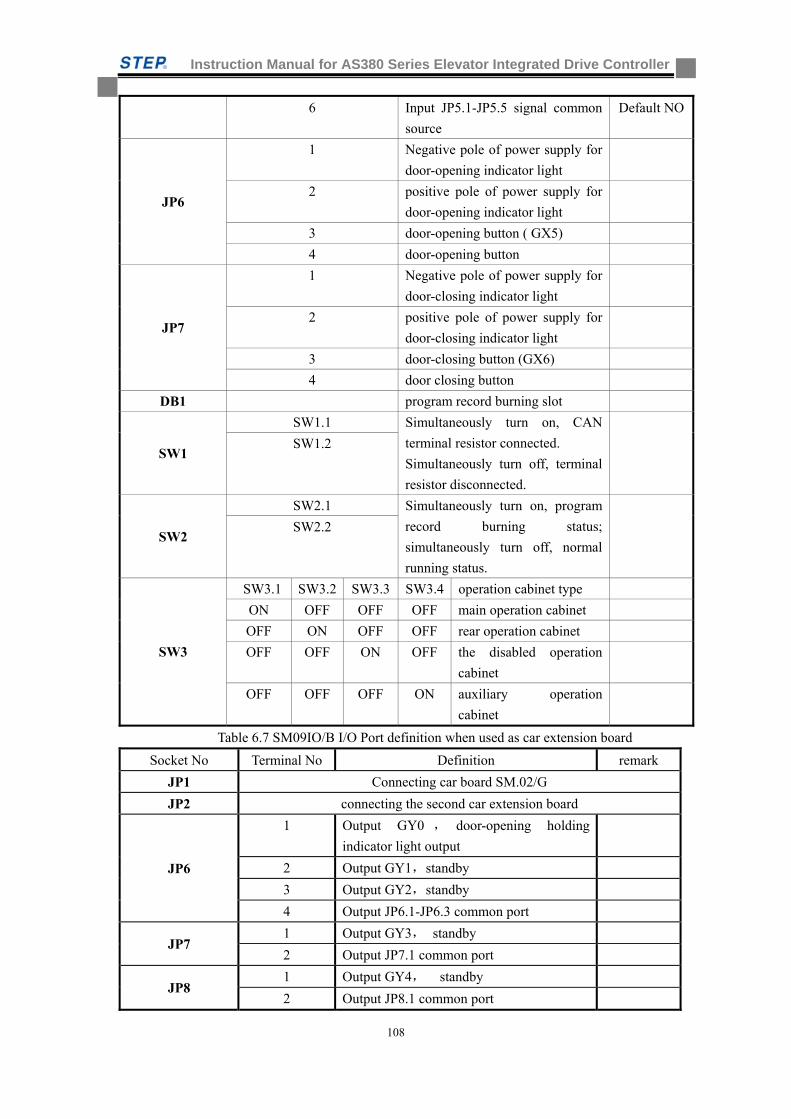
Instruction Manual for AS380 Series Elevator Integrated Drive Controller
108
6 Input JP5.1-JP5.5 signal common
source
Default NO
JP6
1 Negative pole of power supply for
door-opening indicator light
2 positive pole of power supply for
door-opening indicator light
3 door-opening button ( GX5)
4 door-opening button
JP7
1 Negative pole of power supply for
door-closing indicator light
2 positive pole of power supply for
door-closing indicator light
3 door-closing button (GX6)
4 door closing button
DB1 program record burning slot
SW1
SW1.1 Simultaneously turn on, CAN
terminal resistor connected.
Simultaneously turn off, terminal
resistor disconnected.
SW1.2
SW2
SW2.1 Simultaneously turn on, program
record burning status;
simultaneously turn off, normal
running status.
SW2.2
SW3
SW3.1 SW3.2 SW3.3 SW3.4 operation cabinet type
ON OFF OFF OFF main operation cabinet
OFF ON OFF OFF rear operation cabinet
OFF OFF ON OFF the disabled operation
cabinet
OFF OFF OFF ON auxiliary operation
cabinet
Table 6.7 SM09IO/B I/O Port definition when used as car extension board
Socket No Terminal No Definition remark
JP1 Connecting car board SM.02/G
JP2 connecting the second car extension board
JP6
1 Output GY0 , door-opening holding
indicator light output
2 Output GY1,standby
3 Output GY2,standby
4 Output JP6.1-JP6.3 common port
JP7 1 Output GY3, standby
2 Output JP7.1 common port
JP8 1 Output GY4, standby
2 Output JP8.1 common port
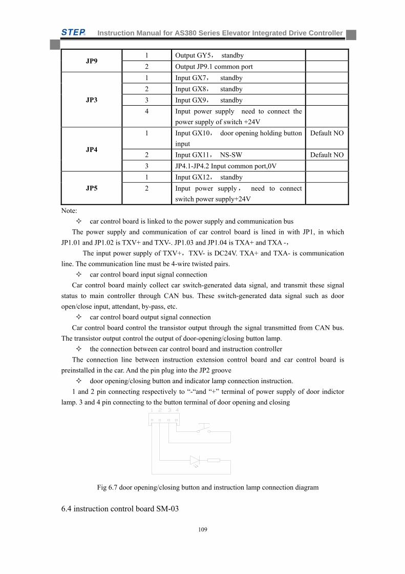
Instruction Manual for AS380 Series Elevator Integrated Drive Controller
109
JP9 1 Output GY5, standby
2 Output JP9.1 common port
JP3
1 Input GX7, standby
2 Input GX8, standby
3 Input GX9, standby
4 Input power supply need to connect the
power supply of switch +24V
JP4
1 Input GX10, door opening holding button
input
Default NO
2 Input GX11, NS-SW Default NO
3 JP4.1-JP4.2 Input common port,0V
JP5
1 Input GX12, standby
2 Input power supply, need to connect
switch power supply+24V
Note:
car control board is linked to the power supply and communication bus
The power supply and communication of car control board is lined in with JP1, in which
JP1.01 and JP1.02 is TXV+ and TXV-. JP1.03 and JP1.04 is TXA+ and TXA -,
The input power supply of TXV+,TXV- is DC24V. TXA+ and TXA- is communication
line. The communication line must be 4-wire twisted pairs.
car control board input signal connection
Car control board mainly collect car switch-generated data signal, and transmit these signal
status to main controller through CAN bus. These switch-generated data signal such as door
open/close input, attendant, by-pass, etc.
car control board output signal connection
Car control board control the transistor output through the signal transmitted from CAN bus.
The transistor output control the output of door-opening/closing button lamp.
the connection between car control board and instruction controller
The connection line between instruction extension control board and car control board is
preinstalled in the car. And the pin plug into the JP2 groove
door opening/closing button and indicator lamp connection instruction.
1 and 2 pin connecting respectively to “-“and “+” terminal of power supply of door indictor
lamp. 3 and 4 pin connecting to the button terminal of door opening and closing
Fig 6.7 door opening/closing button and instruction lamp connection diagram
6.4 instruction control board SM-03
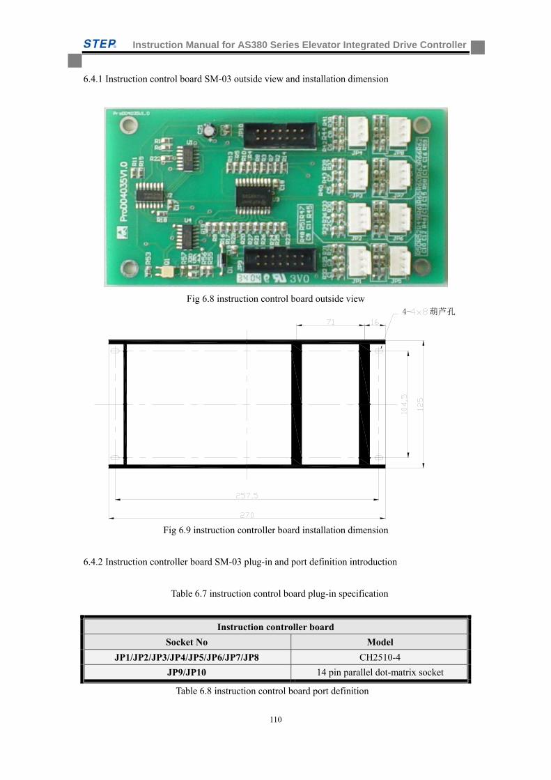
Instruction Manual for AS380 Series Elevator Integrated Drive Controller
110
6.4.1 Instruction control board SM-03 outside view and installation dimension
Fig 6.8 instruction control board outside view 4- 葫芦孔
Fig 6.9 instruction controller board installation dimension
6.4.2 Instruction controller board SM-03 plug-in and port definition introduction
Table 6.7 instruction control board plug-in specification
Table 6.8 instruction control board port definition
Instruction controller board
Socket No Model
JP1/JP2/JP3/JP4/JP5/JP6/JP7/JP8 CH2510-4
JP9/JP10 14 pin parallel dot-matrix socket
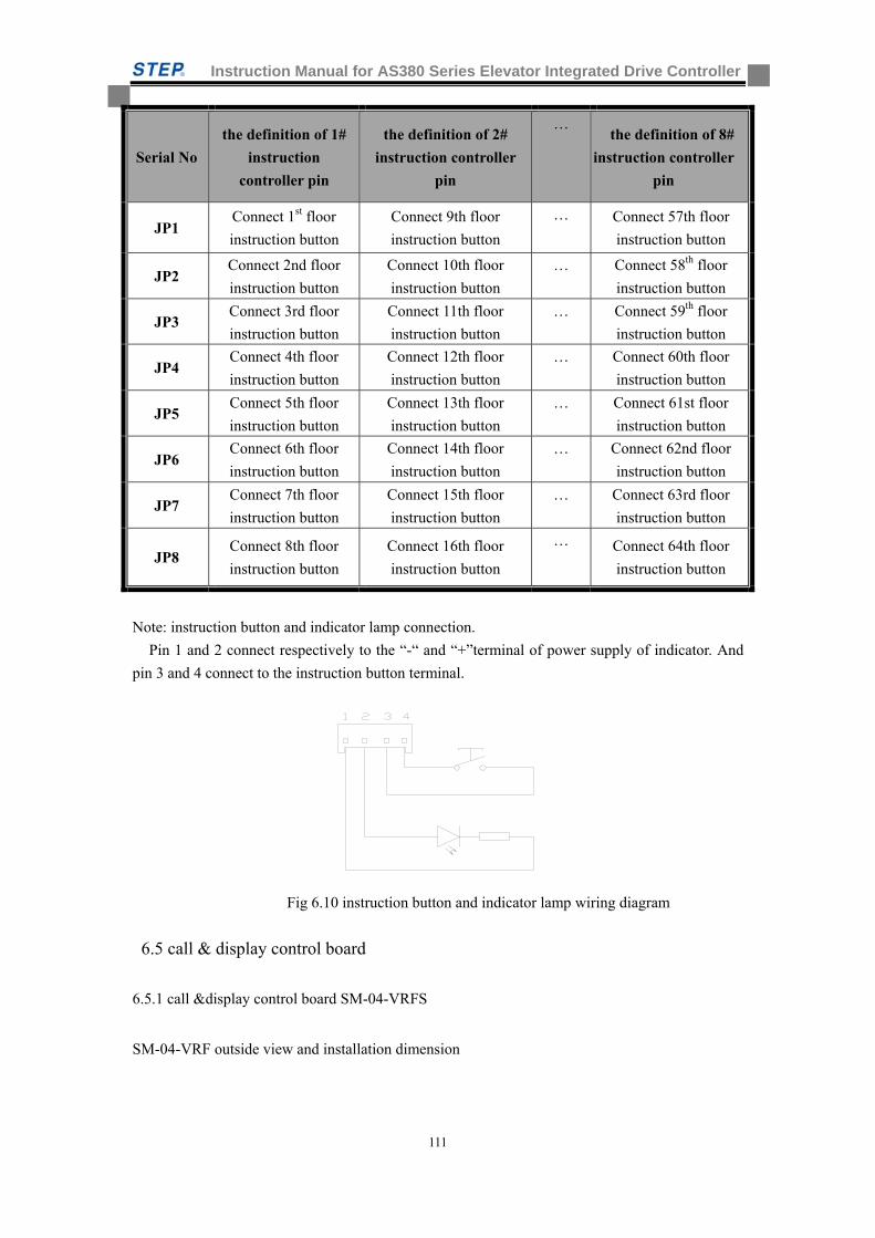
Instruction Manual for AS380 Series Elevator Integrated Drive Controller
111
Serial No
the definition of 1#
instruction
controller pin
the definition of 2#
instruction controller
pin
… the definition of 8#
instruction controller
pin
JP1 Connect 1st floor
instruction button
Connect 9th floor
instruction button
… Connect 57th floor
instruction button
JP2 Connect 2nd floor
instruction button
Connect 10th floor
instruction button
… Connect 58th floor
instruction button
JP3 Connect 3rd floor
instruction button
Connect 11th floor
instruction button
… Connect 59th floor
instruction button
JP4 Connect 4th floor
instruction button
Connect 12th floor
instruction button
… Connect 60th floor
instruction button
JP5 Connect 5th floor
instruction button
Connect 13th floor
instruction button
… Connect 61st floor
instruction button
JP6 Connect 6th floor
instruction button
Connect 14th floor
instruction button
… Connect 62nd floor
instruction button
JP7 Connect 7th floor
instruction button
Connect 15th floor
instruction button
… Connect 63rd floor
instruction button
JP8 Connect 8th floor
instruction button
Connect 16th floor
instruction button
… Connect 64th floor
instruction button
Note: instruction button and indicator lamp connection.
Pin 1 and 2 connect respectively to the “-“ and “+”terminal of power supply of indicator. And
pin 3 and 4 connect to the instruction button terminal.
Fig 6.10 instruction button and indicator lamp wiring diagram
6.5 call & display control board
6.5.1 call &display control board SM-04-VRFS
SM-04-VRF outside view and installation dimension
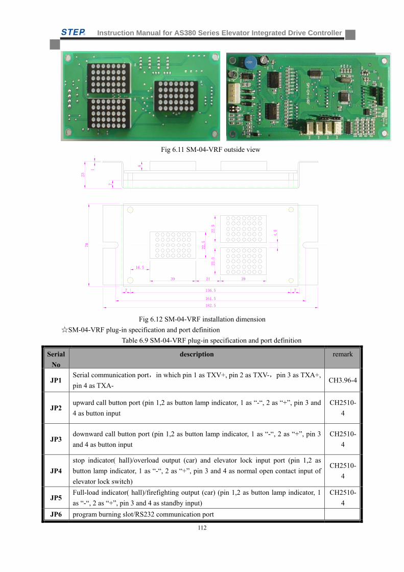
Instruction Manual for AS380 Series Elevator Integrated Drive Controller
112
Fig 6.11 SM-04-VRF outside view
7
23
1
182.5
8
161.5
22.5
39
70
21 394.522
.5
22.5
16.5
7 7136.5
Fig 6.12 SM-04-VRF installation dimension
SM-04-VRF plug-in specification and port definition
Table 6.9 SM-04-VRF plug-in specification and port definition
Serial
No
description remark
JP1 Serial communication port,in which pin 1 as TXV+, pin 2 as TXV-,pin 3 as TXA+,
pin 4 as TXA- CH3.96-4
JP2 upward call button port (pin 1,2 as button lamp indicator, 1 as “-“, 2 as “+”, pin 3 and
4 as button input
CH2510-
4
JP3 downward call button port (pin 1,2 as button lamp indicator, 1 as “-“, 2 as “+”, pin 3
and 4 as button input
CH2510-
4
JP4
stop indicator( hall)/overload output (car) and elevator lock input port (pin 1,2 as
button lamp indicator, 1 as “-“, 2 as “+”, pin 3 and 4 as normal open contact input of
elevator lock switch)
CH2510-
4
JP5 Full-load indicator( hall)/firefighting output (car) (pin 1,2 as button lamp indicator, 1
as “-“, 2 as “+”, pin 3 and 4 as standby input)
CH2510-
4
JP6 program burning slot/RS232 communication port
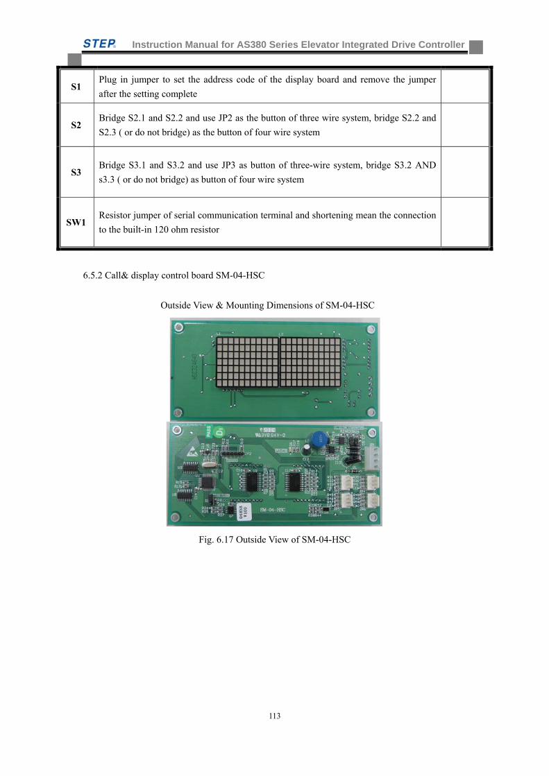
Instruction Manual for AS380 Series Elevator Integrated Drive Controller
113
S1 Plug in jumper to set the address code of the display board and remove the jumper
after the setting complete
S2 Bridge S2.1 and S2.2 and use JP2 as the button of three wire system, bridge S2.2 and
S2.3 ( or do not bridge) as the button of four wire system
S3 Bridge S3.1 and S3.2 and use JP3 as button of three-wire system, bridge S3.2 AND
s3.3 ( or do not bridge) as button of four wire system
SW1 Resistor jumper of serial communication terminal and shortening mean the connection
to the built-in 120 ohm resistor
6.5.2 Call& display control board SM-04-HSC
Outside View & Mounting Dimensions of SM-04-HSC
Fig. 6.17 Outside View of SM-04-HSC
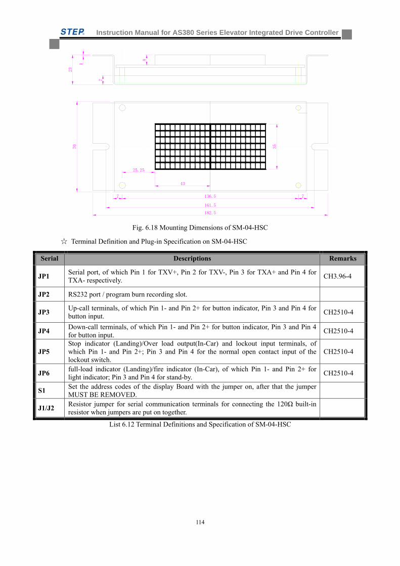
Instruction Manual for AS380 Series Elevator Integrated Drive Controller
114
7
23
1
182.5
161.5
70
7 7136.5
43
35
25.25
8
Fig. 6.18 Mounting Dimensions of SM-04-HSC
Terminal Definition and Plug-in Specification on SM-04-HSC
Serial Descriptions Remarks
JP1 Serial port, of which Pin 1 for TXV+, Pin 2 for TXV-, Pin 3 for TXA+ and Pin 4 for TXA- respectively.
CH3.96-4
JP2 RS232 port / program burn recording slot.
JP3 Up-call terminals, of which Pin 1- and Pin 2+ for button indicator, Pin 3 and Pin 4 for button input.
CH2510-4
JP4 Down-call terminals, of which Pin 1- and Pin 2+ for button indicator, Pin 3 and Pin 4 for button input.
CH2510-4
JP5 Stop indicator (Landing)/Over load output(In-Car) and lockout input terminals, of which Pin 1- and Pin 2+; Pin 3 and Pin 4 for the normal open contact input of the lockout switch.
CH2510-4
JP6 full-load indicator (Landing)/fire indicator (In-Car), of which Pin 1- and Pin 2+ for light indicator; Pin 3 and Pin 4 for stand-by.
CH2510-4
S1 Set the address codes of the display Board with the jumper on, after that the jumper MUST BE REMOVED.
J1/J2 Resistor jumper for serial communication terminals for connecting the 120Ω built-in resistor when jumpers are put on together.
List 6.12 Terminal Definitions and Specification of SM-04-HSC
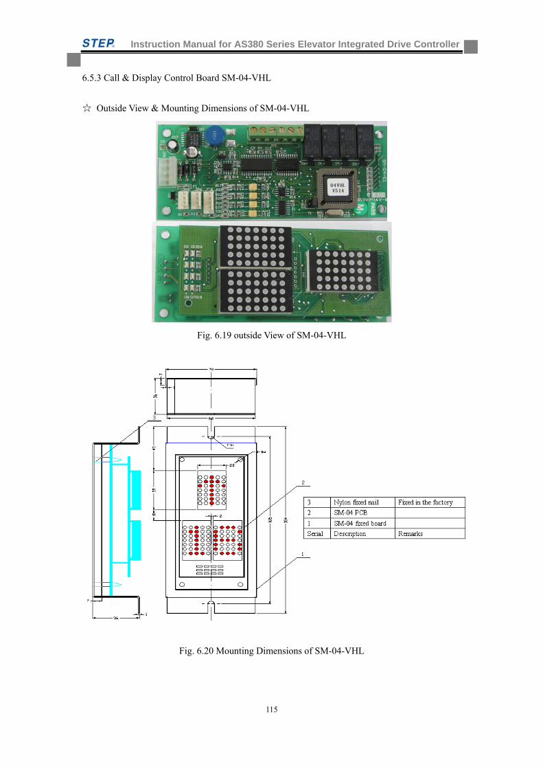
Instruction Manual for AS380 Series Elevator Integrated Drive Controller
115
6.5.3 Call & Display Control Board SM-04-VHL
Outside View & Mounting Dimensions of SM-04-VHL
Fig. 6.19 outside View of SM-04-VHL
Fig. 6.20 Mounting Dimensions of SM-04-VHL
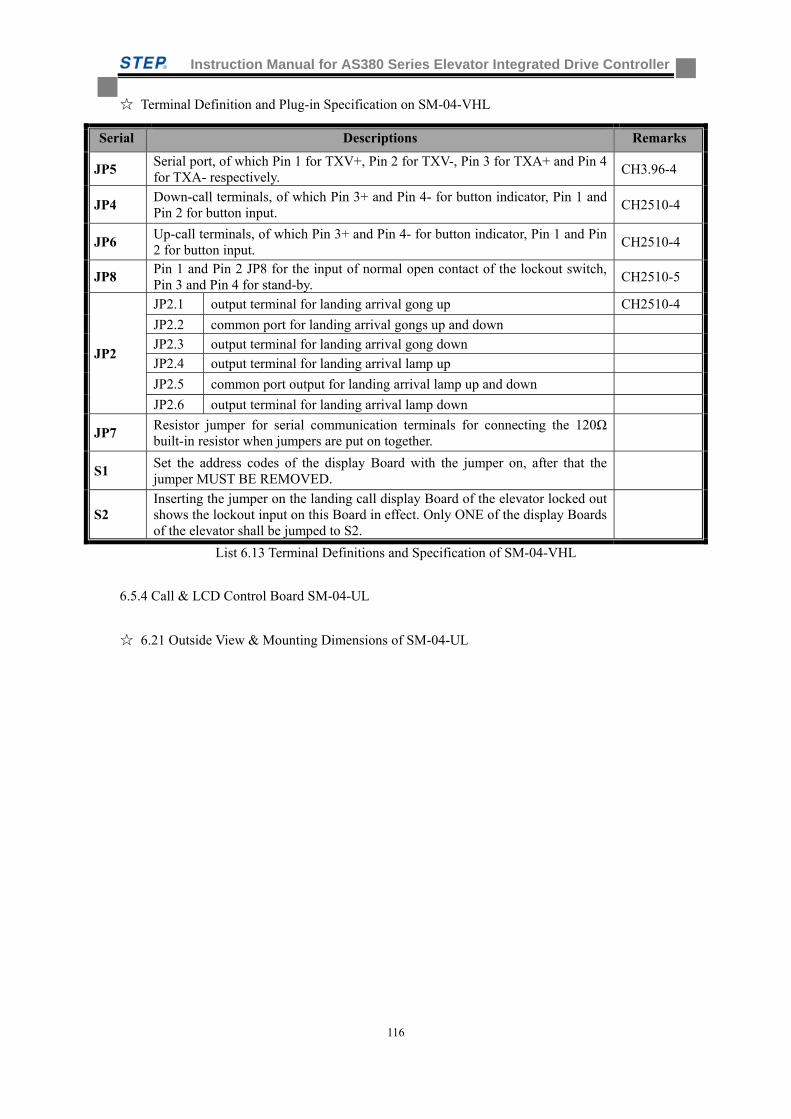
Instruction Manual for AS380 Series Elevator Integrated Drive Controller
116
Terminal Definition and Plug-in Specification on SM-04-VHL
Serial Descriptions Remarks
JP5 Serial port, of which Pin 1 for TXV+, Pin 2 for TXV-, Pin 3 for TXA+ and Pin 4 for TXA- respectively.
CH3.96-4
JP4 Down-call terminals, of which Pin 3+ and Pin 4- for button indicator, Pin 1 and Pin 2 for button input.
CH2510-4
JP6 Up-call terminals, of which Pin 3+ and Pin 4- for button indicator, Pin 1 and Pin 2 for button input.
CH2510-4
JP8 Pin 1 and Pin 2 JP8 for the input of normal open contact of the lockout switch, Pin 3 and Pin 4 for stand-by.
CH2510-5
JP2
JP2.1 output terminal for landing arrival gong up CH2510-4
JP2.2 common port for landing arrival gongs up and down
JP2.3 output terminal for landing arrival gong down
JP2.4 output terminal for landing arrival lamp up
JP2.5 common port output for landing arrival lamp up and down
JP2.6 output terminal for landing arrival lamp down
JP7 Resistor jumper for serial communication terminals for connecting the 120Ω built-in resistor when jumpers are put on together.
S1 Set the address codes of the display Board with the jumper on, after that the jumper MUST BE REMOVED.
S2 Inserting the jumper on the landing call display Board of the elevator locked out shows the lockout input on this Board in effect. Only ONE of the display Boards of the elevator shall be jumped to S2.
List 6.13 Terminal Definitions and Specification of SM-04-VHL
6.5.4 Call & LCD Control Board SM-04-UL
6.21 Outside View & Mounting Dimensions of SM-04-UL
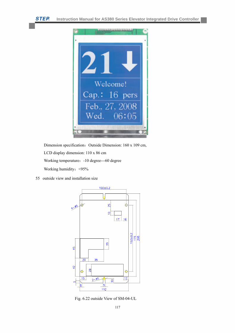
Instruction Manual for AS380 Series Elevator Integrated Drive Controller
117
Dimension specification:Outside Dimension: 160 x 109 cm,
LCD display dimension: 110 x 86 cm
Working temperature:-10 degree---60 degree
Working humidity:<95%
55 outside view and installation size
Fig. 6.22 outside View of SM-04-UL
Instruction Manual for AS380 Series Elevator Integrated Drive Controller
118
Terminal Definition and Plug-in Specification on SM-04-UL
Serial Descriptions Remarks
JP8 Serial port, of which Pin 1 for TXV+, Pin 2 for TXV-, Pin 3 for TXA+ and Pin 4 for TXA- respectively.
CH3.96-4
JP11 Down-call terminals, of which Pin 1 -and Pin 2 + for button indicator, Pin 3 and Pin 4 for button input.
CH2510-4
JP12 Up-call terminals, of which Pin 1- and Pin 2+ for button indicator, Pin 3 and Pin 4 for button input.
CH2510-4
JP10 Pin 3 and Pin 4 for the input of normal open contact of the lockout switch, Pin 1 and Pin 2 for stand-by.
CH2510-5
SW1 Resistor jumper for serial communication terminals for connecting the 120Ω built-in resistor when jumpers are put on together. Both ON for connection of CAN terminal resistor, both OFF for disconnection of it.
SW2 SW2.1 ON for setting number of passengers allowed boarding in car by pressing on up and down buttons, OFF for normal. SW2.2 ON for display in English, OFF for display in Chinese.
SW5
SW5.1 ON for setting address codes by pressing on up and down buttons, OFF for normal. SW5.2 ON for selecting time options by pressing on up button, for changing in time by pressing on down button, OFF for normal. Both SW2.1 and SW5.1 ON before power-on for adjusting display contrast by pressing on up and down buttons.
List 6.14 Terminal Definitions and Specification of SM-04-UL
Table 6-15 function description
Address Codes SW5.1 ON, press on up and down call buttons. Range of Codes 0 to 48 Time Setting SW5.2 ON, press on up call button to select time options, press on down call button to
make changes in time. Passengers Allowed for Entry in Car
SW2.1 ON, press on up and down call buttons to set the number of passengers allowed boarding in car.
Display Contrast Adjustment
in hardware Adjust the value of resistance in R53 by turning a screwdriver while watching the change in contrast. It allows for a wide range in adjustment.
in software Set both SW2.1 and SW5.1 ON before switch on power and adjust the display contrast by pressing on up and down call buttons, only good for fine adjustment.
Language Setting SW2.2 ON for display in English, OFF for display in Chinese.
6.5.5 Car Call & LCD Control Board SM-04-VL
Outside View & Mounting Dimensions of Landing call display Board SM-04-VL16/A
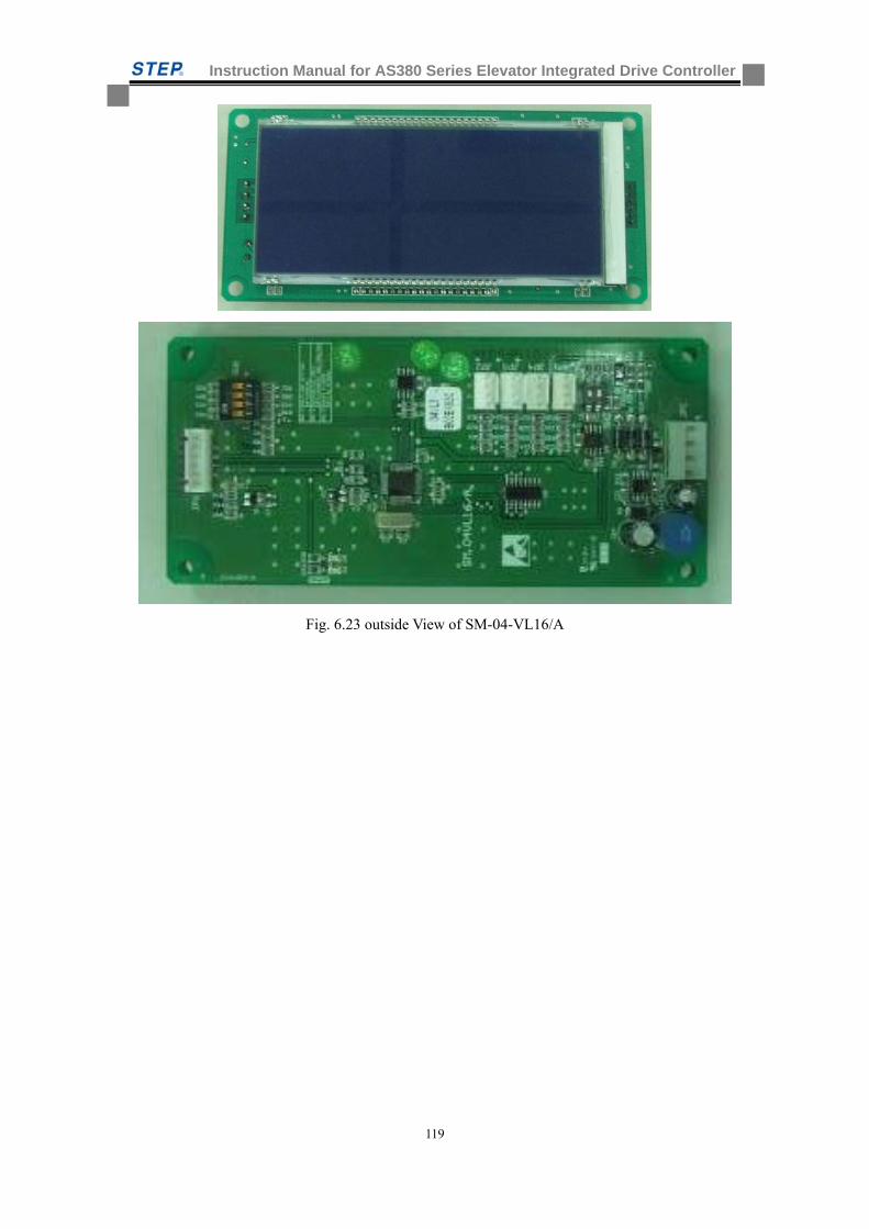
Instruction Manual for AS380 Series Elevator Integrated Drive Controller
119
Fig. 6.23 outside View of SM-04-VL16/A
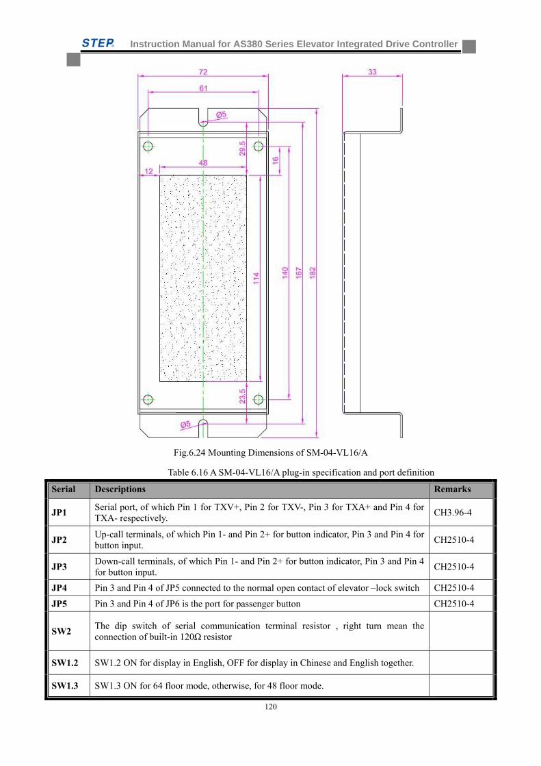
Instruction Manual for AS380 Series Elevator Integrated Drive Controller
120
Fig.6.24 Mounting Dimensions of SM-04-VL16/A
Table 6.16 A SM-04-VL16/A plug-in specification and port definition
Serial Descriptions Remarks
JP1 Serial port, of which Pin 1 for TXV+, Pin 2 for TXV-, Pin 3 for TXA+ and Pin 4 for TXA- respectively.
CH3.96-4
JP2 Up-call terminals, of which Pin 1- and Pin 2+ for button indicator, Pin 3 and Pin 4 for button input.
CH2510-4
JP3 Down-call terminals, of which Pin 1- and Pin 2+ for button indicator, Pin 3 and Pin 4 for button input.
CH2510-4
JP4 Pin 3 and Pin 4 of JP5 connected to the normal open contact of elevator –lock switch CH2510-4
JP5 Pin 3 and Pin 4 of JP6 is the port for passenger button CH2510-4
SW2 The dip switch of serial communication terminal resistor , right turn mean the connection of built-in 120Ω resistor
SW1.2 SW1.2 ON for display in English, OFF for display in Chinese and English together.
SW1.3 SW1.3 ON for 64 floor mode, otherwise, for 48 floor mode.
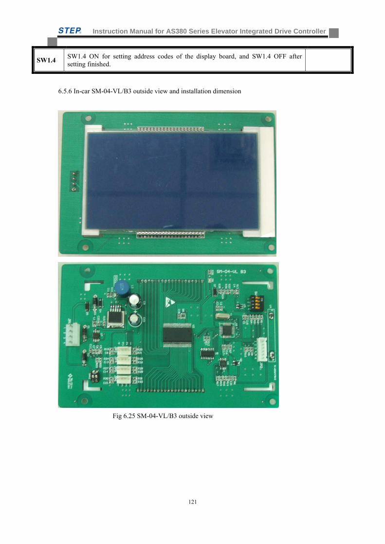
Instruction Manual for AS380 Series Elevator Integrated Drive Controller
121
SW1.4 SW1.4 ON for setting address codes of the display board, and SW1.4 OFF after setting finished.
6.5.6 In-car SM-04-VL/B3 outside view and installation dimension
Fig 6.25 SM-04-VL/B3 outside view
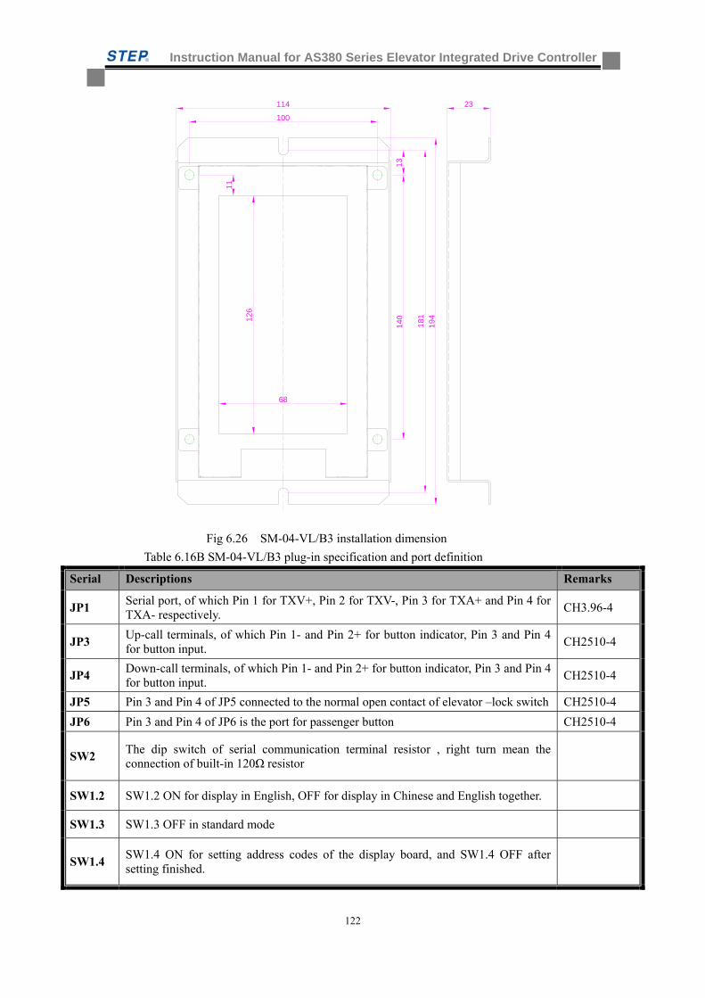
Instruction Manual for AS380 Series Elevator Integrated Drive Controller
122
140
194
100
114
181
23
126
68
11
13
Fig 6.26 SM-04-VL/B3 installation dimension
Table 6.16B SM-04-VL/B3 plug-in specification and port definition
Serial Descriptions Remarks
JP1 Serial port, of which Pin 1 for TXV+, Pin 2 for TXV-, Pin 3 for TXA+ and Pin 4 for TXA- respectively.
CH3.96-4
JP3 Up-call terminals, of which Pin 1- and Pin 2+ for button indicator, Pin 3 and Pin 4 for button input.
CH2510-4
JP4 Down-call terminals, of which Pin 1- and Pin 2+ for button indicator, Pin 3 and Pin 4 for button input.
CH2510-4
JP5 Pin 3 and Pin 4 of JP5 connected to the normal open contact of elevator –lock switch CH2510-4
JP6 Pin 3 and Pin 4 of JP6 is the port for passenger button CH2510-4
SW2 The dip switch of serial communication terminal resistor , right turn mean the connection of built-in 120Ω resistor
SW1.2 SW1.2 ON for display in English, OFF for display in Chinese and English together.
SW1.3 SW1.3 OFF in standard mode
SW1.4 SW1.4 ON for setting address codes of the display board, and SW1.4 OFF after setting finished.
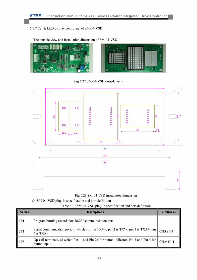
Instruction Manual for AS380 Series Elevator Integrated Drive Controller
123
6.5.7 Call& LED display control panel SM-04-VSD
The outside view and installation dimension of SM-04-VSD
Fig 6.27 SM-04-VSD outside view
28
237260
163
178
137
42
4213.9
2 4
1.3
36 58
6.3
Fig 6.28 SM-04-VSD installation dimension
SM-04-VSD plug-in specification and port definition
Table 6.17 SM-04-VSD plug-in specification and port definition
Serial Descriptions Remarks
JP1 Program burning record slot/ RS232 communication port
JP2 Serial communication port, in which pin 1 is TXV+, pin 2 is TXV-, pin 3 is TXA+, pin 4 is TXA-
CH3.96-4
JP3 Up-call terminals, of which Pin 1- and Pin 2+ for button indicator, Pin 3 and Pin 4 for button input.
CH2510-4
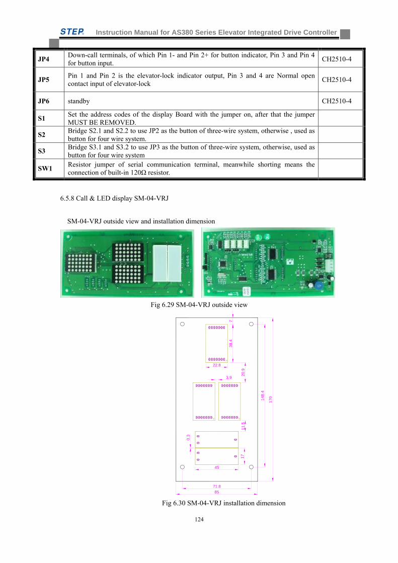
Instruction Manual for AS380 Series Elevator Integrated Drive Controller
124
JP4 Down-call terminals, of which Pin 1- and Pin 2+ for button indicator, Pin 3 and Pin 4 for button input.
CH2510-4
JP5 Pin 1 and Pin 2 is the elevator-lock indicator output, Pin 3 and 4 are Normal open contact input of elevator-lock
CH2510-4
JP6 standby CH2510-4
S1 Set the address codes of the display Board with the jumper on, after that the jumper MUST BE REMOVED.
S2 Bridge S2.1 and S2.2 to use JP2 as the button of three-wire system, otherwise , used as button for four wire system.
S3 Bridge S3.1 and S3.2 to use JP3 as the button of three-wire system, otherwise, used as button for four wire system
SW1 Resistor jumper of serial communication terminal, meanwhile shorting means the connection of built-in 120Ω resistor.
6.5.8 Call & LED display SM-04-VRJ
SM-04-VRJ outside view and installation dimension
Fig 6.29 SM-04-VRJ outside view
148.
4
71.8
170
85
39.4
22.8
45
1720
.911
.5
0.3
3.9
7
Fig 6.30 SM-04-VRJ installation dimension

Instruction Manual for AS380 Series Elevator Integrated Drive Controller
125
SM-04-VRJ plug-in specification and port definition
Table 6.18 SM-04-VRJ plug-in specification and port definition
Serial Descriptions Remarks
JP1 Serial port, of which Pin 1 for TXV+, Pin 2 for TXV-, Pin 3 for TXA+ and Pin 4 for TXA- respectively.
CH3.96-4
JP2 Down-call terminals, of which Pin 1 -and Pin 2 + for button indicator, Pin 3 and Pin 4 for button input.
CH2510-4
JP3 Up-call terminals, of which Pin 1- and Pin 2+ for button indicator, Pin 3 and Pin 4 for button input.
CH2510-4
JP4 Pin 3 and Pin 4 for the input of normal open contact of the lockout switch, Pin 1 and Pin 2 for stand-by.
CH2510-4
JP5 standby CH2510-4
JP6 Program burning record slot/ RS232 communication port
S1 Set the address codes of the display Board with the jumper on, after that the jumper MUST BE REMOVED.
S2 Bridge S2.1 and S2.2 to use JP2 as the button of three-wire system, otherwise, used as button for four wire system.
S3 Bridge S3.1 and S3.2 to use JP3 as the button of three-wire system, otherwise, used as button for four wire system
SW1 Resistor jumper of serial communication terminal, meanwhile shorting means the connection of built-in 120Ω resistor.
6.5.9 Miscellaneous (A List of Display Codes)
A list of performance displays
Displays in Car No Voice Forecast
Inspection Normal No
Special
symbol/otherwise
Re-leveling at power off Normal No
Special
symbol/otherwise
Independent Normal No
Special
symbol/otherwise
Fireman Normal No
Special
symbol/otherwise
Safety circuit off Normal No
Special
symbol/otherwise
Lockout Normal No
Special
symbol/otherwise
Breakdown Normal No
Special
symbol/otherwise
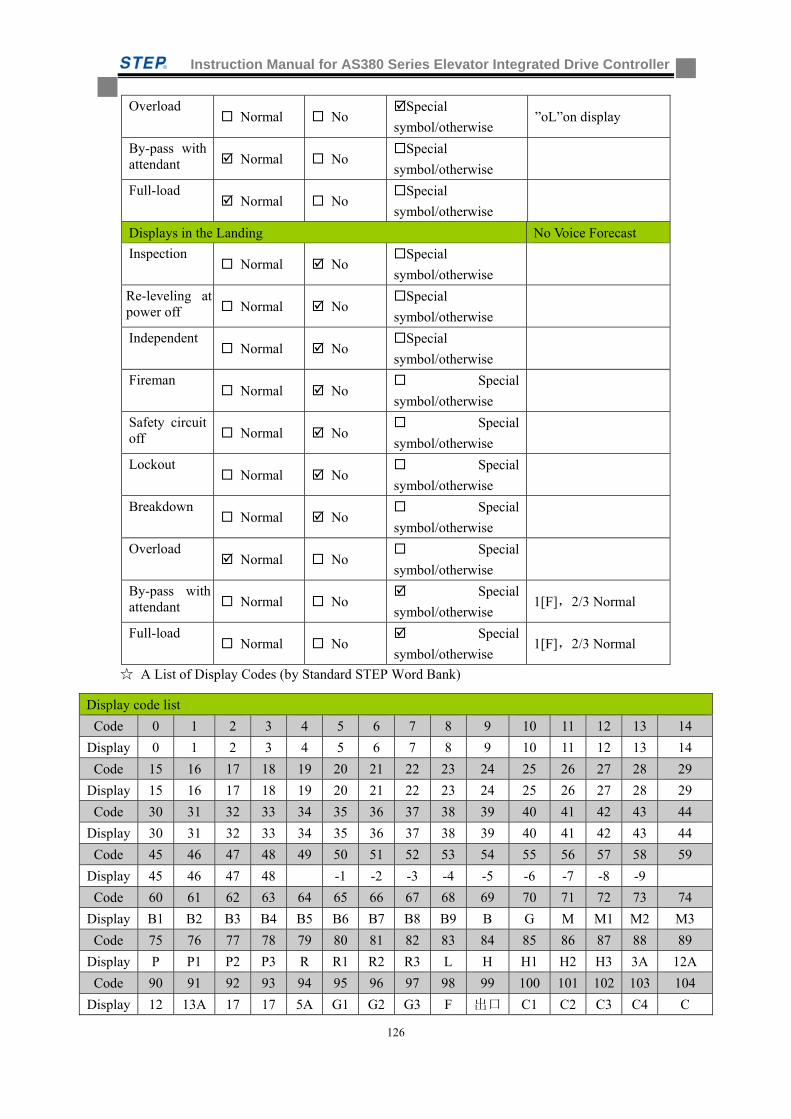
Instruction Manual for AS380 Series Elevator Integrated Drive Controller
126
Overload Normal No
Special
symbol/otherwise ”oL”on display
By-pass with attendant Normal No
Special
symbol/otherwise
Full-load Normal No
Special
symbol/otherwise
Displays in the Landing No Voice Forecast
Inspection Normal No
Special
symbol/otherwise
Re-leveling at power off Normal No
Special
symbol/otherwise
Independent Normal No
Special
symbol/otherwise
Fireman Normal No
Special
symbol/otherwise
Safety circuit off Normal No
Special
symbol/otherwise
Lockout Normal No
Special
symbol/otherwise
Breakdown Normal No
Special
symbol/otherwise
Overload Normal No
Special
symbol/otherwise
By-pass with attendant Normal No
Special
symbol/otherwise 1[F],2/3 Normal
Full-load Normal No
Special
symbol/otherwise 1[F],2/3 Normal
A List of Display Codes (by Standard STEP Word Bank)
Display code list
Code 0 1 2 3 4 5 6 7 8 9 10 11 12 13 14
Display 0 1 2 3 4 5 6 7 8 9 10 11 12 13 14
Code 15 16 17 18 19 20 21 22 23 24 25 26 27 28 29
Display 15 16 17 18 19 20 21 22 23 24 25 26 27 28 29
Code 30 31 32 33 34 35 36 37 38 39 40 41 42 43 44
Display 30 31 32 33 34 35 36 37 38 39 40 41 42 43 44
Code 45 46 47 48 49 50 51 52 53 54 55 56 57 58 59
Display 45 46 47 48 -1 -2 -3 -4 -5 -6 -7 -8 -9
Code 60 61 62 63 64 65 66 67 68 69 70 71 72 73 74
Display B1 B2 B3 B4 B5 B6 B7 B8 B9 B G M M1 M2 M3
Code 75 76 77 78 79 80 81 82 83 84 85 86 87 88 89
Display P P1 P2 P3 R R1 R2 R3 L H H1 H2 H3 3A 12A
Code 90 91 92 93 94 95 96 97 98 99 100 101 102 103 104
Display 12 13A 17 17 5A G1 G2 G3 F 出口 C1 C2 C3 C4 C
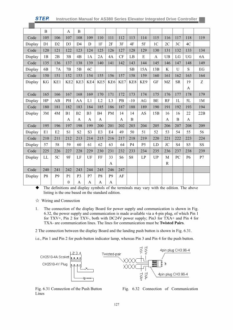
Instruction Manual for AS380 Series Elevator Integrated Drive Controller
127
B A B
Code 105 106 107 108 109 110 111 112 113 114 115 116 117 118 119
Display D1 D2 D3 D4 D 1F 2F 3F 4F 5F 1C 2C 3C 4C
Code 120 121 122 123 124 125 126 127 128 129 130 131 132 133 134
Display 1B 2B 3B 4B 1A 2A 4A CF LB E A UB LG UG 6A
Code 135 136 137 138 139 140 141 142 143 144 145 146 147 148 149
Display 6B 7A 7B 5B 6C SB 15A 13B K U S EG
Code 150 151 152 153 154 155 156 157 158 159 160 161 162 163 164
Display KG KE1 KE2 KE3 KE4 KE5 KE6 KE7 KE8 KE9 GF MZ SR 19
A
Z
Code 165 166 167 168 169 170 171 172 173 174 175 176 177 178 179
Display HP AB PH AA L1 L2 L3 PB -10 AG BE RF 1L 5L 1M
Code 180 181 182 183 184 185 186 187 188 189 190 191 192 193 194
Display 3M 4M B1
A
B2
A
B3
A
B4
A
PM 14
A
14
B
AS 15B 16
A
16
B
22
A
22B
Code 195 196 197 198 199 200 201 202 203 204 205 206 207 208 209
Display E1 E2 S1 S2 S3 E3 E4 49 50 51 52 53 54 55 56
Code 210 211 212 213 214 215 216 217 218 219 220 221 222 223 224
Display 57 58 59 60 61 62 63 64 P4 P5 LD JC S4 S5 SS
Code 225 226 227 228 229 230 231 232 233 234 235 236 237 238 239
Display LL 5C 9F LF UF FF 33
A
S6 S8 LP UP M
R
PC P6 P7
Code 240 241 242 243 244 245 246 247
Display P8 P9 P1
0
P3
A
P7
A
P8
A
P9
A
AF
The definitions and display symbols of the terminals may vary with the edition. The above listing is the one based on the standard edition.
Wiring and Connection
1. The connection of the display Board for power supply and communication is shown in Fig. 6.32, the power supply and communication is made available via a 4-pin plug, of which Pin 1 for TXV+, Pin 2 for TXV-, both with DC24V power supply; Pin3 for TXA+ and Pin 4 for TXA- are communication lines. The lines for communication must be Twisted Pairs.
2 The connection between the display Board and the landing push button is shown in Fig. 6.31.
i.e., Pin 1 and Pin 2 for push-button indicator lamp, whereas Pin 3 and Pin 4 for the push button.
Fig. 6.31 Connection of the Push Button Fig. 6.32 Connection of Communication Lines
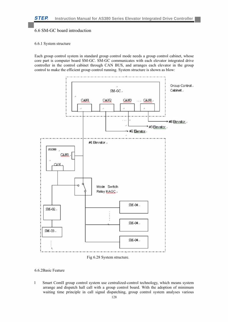
Instruction Manual for AS380 Series Elevator Integrated Drive Controller
128
6.6 SM-GC board introduction
6.6.1 System structure
Each group control system in standard group control mode needs a group control cabinet, whose core part is computer board SM-GC. SM-GC communicates with each elevator integrated drive controller in the control cabinet through CAN BUS, and arranges each elevator in the group control to make the efficient group control running. System structure is shown as blow:
Fig 6.28 System structure.
6.6.2Basic Feature
1 Smart ComII group control system use centralized-control technology, which means system arrange and dispatch hall call with a group control board. With the adoption of minimum waiting time principle in call signal dispatching, group control system analyses various
Instruction Manual for AS380 Series Elevator Integrated Drive Controller
129
situations including floor height, car call and hall call situation, elevator transcending situation and reverse direction situation to dispatch hall call to the elevator which can respond most quickly. Group control system can increase the efficiency of the elevator.
2 Smart ComII group control system can control up to 8 elevators at the same time; the max floor number of each elevator is 48.
3 Group control board use CAN BUS serial communication method to communicate with elevator control board, which assure the credible and hi-speed data transfer.
4 Group control system has back up protection function. If group control system has any problem, it will cutoff the power supply. The elevators in the group control system can run normally in single mode. When the group control system recover to normal, all the elevators in system will transfer to group control mode automatically.
5 Group control system can cutoff the fault elevator. If the system find the elevator which has received the hall call does not respond (such as door-closing), the system will cutoff this fault elevator and re-dispatch the hall call to assure the users not to wait a long time.
6 If elevator control board runs normally, the hall call is send to group control board from elevator control board. The group control system then send call registration signal to call controller through elevator control board to light the call button. If elevator control board is power off, the group control system will communicate with call controller directly to assure call controller still have effect in the system.
7 There are LEDs on the group control board; users can monitor the communication status between group control board and elevator control board through these LEDs. Input terminals in the group control board also have the corresponding LEDs to indicate the ON/OFF situation.
6.6.3Main Functions
1 Homing function: automatically homing function activation is required with related parameter setting. In group control system, if there is no elevator at home base and the elevator which can back to home immediately has no hall call and car call register, then the elevator will homing at once and standby with door closed. In this way can improve the home base carrying capacity. Homing function has two mode: in standard mode, only one elevator will return to home base automatically without time delay, in the mode of designating the number of elevator automatically homing, the number of elevator automatically homing is set up to four unit. Meanwhile, the homing time delay can also be set. In this mode, it is required to use the second setting software to set the homing elevator quantity and time delay, apart from using standard setting software for homing function activation.
2 Dispersion standby function: dispersion standby function activation is required with related parameter setting, it also has two modes. When all elevators in the system maintain standby status for one minute, group control system activate the dispersion standby function: a. if there is no elevator at home base and the floor below home base, system will send an elevator which can reach home base most easily to home base and standby with door closed. b. If there are more than two elevators running normally in the group control system and there is no elevator above central floor, the system will send an elevator which can reach home base most easily to the up standby floor with door closed. In the mode of designating the floor for elevator to standby, if all elevator maintain standby status for a certain period of time ( the time set by parameter ) and the floor designated for elevator to standby ( max set to four) has no elevator , the group control system will dispatch the easiest-reach elevator to the floor designated for elevator to standby with door closed. In this mode, it is required to use the second setting software to set the floors designated for standby and time delay for dispersion standby, apart from using standard setting software for dispersion standby function activation.
Instruction Manual for AS380 Series Elevator Integrated Drive Controller
130
3 Up peak service: When this function is chosen, system will start up peak service if the up running elevator from home base has more than three call register at up peak time(set by time relay or manual switch). At this time all elevators in the system will back to home base as soon as the completion of response to the hall call and car call. System will recover to normal, when the up peak time passed (set by time relay or manual switch).
4 Down peak service: When this function is chosen, system will start down peak service if the down running elevator to the home base has full car situation at down peak time (set by time relay or manual switch). At this time all elevators in the system will back to highest floor and standby with door closed as soon as the completion of response to the hall calls and car calls. System will recover to normal, if the down peak time passed or there is no full car situation for two minutes.
5 None service floor control function: SMART COMII group control system has preinstall two service floor schemes for user. User can use two switches to select (or use two time relay to select). When one of switch set to ON, system will run with the scheme which is set by users. If both switches are off, elevator will run in normal service floor mode. Each schemes need preset. Users can appoint which elevator to response hall call at which floors and they can also appoint elevator to response up call or down call at designated floor.
6 Standard group split function: When the group split mode parameter is set to 0 and the group split switch is set to ON, group control system split into two independent group control system in accordance with the preset value.(which elevators belong to group X, which elevators belong to group Y) When the switch is set to OFF, system is set to normal group control.
7 Partial incomplete split function: To cope with the inconsistency of bottom floors of elevators in the group control system, the group dividing mode parameter can be set to 1, and group should be divided in accordance with the reachable floor (Group Y for the elevator that can reach the lowest floor, Group X for elevator that can not reach the lowest floor). Turn on the group dividing switch and the group control system enters into the down-call incomplete split running mode. At this time, the passengers at the above floor, who want to get to the lowest floor, can register the down-call signal to elevator that can reach the lowest floor. The system with activation of incomplete split function will only dispatch the elevator that can reach the lowest floor to respond. If the down-call from the elevator that can not reach the lowest floor is registered, system will not activate the incomplete split function and dispatch the easiest reachable elevator to respond. For the up-call signal, group control system will not make any split. Meanwhile, to cope with the inconsistency of top floors of elevators in the group control system, the group dividing mode parameter can be set to 2, and group should be divided in accordance with the reachable floor (group Y for the elevator that can reach the top floor, Group X for elevator that can not reach the top floor). Turn on the group dividing switch and group control system enters into the up-call incomplete split running mode. At this time, the passengers at the below floor, who want to get to the top floor, can register the up-call signal to elevator that can reach the top floor. The system with activation of incomplete split function will only dispatch the elevator that can reach the top floor to respond. If the up-call from the elevator that can not reach the top floor is registered, system will not activate the incomplete split function and dispatch the easiest reachable elevator to respond. For the down-call signal, group control system will not make any split. The advantage of adoption of such function is to meet the needs of passengers that want to go to the certain floor while still maintain the running efficiency of group control system.
8 Signal elevator running under special circumstance, if the certain elevator in the group control system encounter difficult in communication with group control system. The elevator will automatically switch to signal elevator running mode.
9 Emergency power running mode:When there is a sudden power cut and need to use back up power, it is necessary for user to choose this function. Considering the back up power’s limited capacity, system will let the elevator back to home base one by one and standby with door open. After all the elevator returned to the home base, group control system will assign
Instruction Manual for AS380 Series Elevator Integrated Drive Controller
131
which elevators to continue operating and which elevators to standby with door closed in accordance with preset parameters. Therefore, backup power overload will never happen.
6.6.4 Call button signal input and call button lamp control
In normal situation, elevator control cabinet is power on, mode switch relay is closed, elevator
integrated drive controller is linked with SM-GC through communication line. SM-04 send the
button signal to the elevator integrated drive controller, and the elevator integrated drive controller
send the button signal to SM-GC through another CAN port (CAN 1) for button signal processing.
SM-GC send the processed button lighting signal to the elevator integrated drive controller and the
elevator integrated drive controller will send the lighting signal through CAN port to SM-04.
SM-04 finally control the button light on/off based on the received signal. If the control cabinet of
certain elevator is power off, the normal close contact of switch relay inside the control cabinet
will connect the CAN communication line of SM-GC and SM-04.SM-GC can directly
communicate with SM-04 of that elevator. It can directly receive the button contact signal sent by
that SM-04 and send lighting signal directly to SM-04.
6.6.5 Overall adjustment principle
In group control system, SM-GC process the hall call’s registration and cancellation. SM-GC will calculate the score for each elevator to response the hall call button and give hall call to the elevator which has highest score.
To minimize the user waiting time, group control system set the following principles
1、 Distance punish
According to the distance between the call button and the elevator, there is a punish score. Normally, one score for one floor, if the floor is higher than normal, the score could be two or three.
2、 Reverse direction punish
According to principle of same direction priority,set a reverse direction punish score while calculating punish score, the principle is show as follow:
a、 Down call above elevator or up call below elevator will get three to eight punish score according to the specific circumstance.
b、 If elevator is running upward and there is no car call or up hall call above, then give the down hall call below the elevator three punish score. In this way, if elevator is running downward and there is no car call or down hall call below, then give the up hall call above the elevator three punish score.
3、 Instruction or call punish
It will take an elevator some time to respond the registered instruction or call signal. If there is any instruction or call registered between the elevator and the new hall call, each instruction or same-direction call which is registered will get three punish score.
4、 Overpass punish
To increase efficiency of the elevator and prevent overpass among elevators, there is an overpass punish when calculate the score. Normally, when there are more than two elevators running in the same direction, the elevators which are not in the first position will get eight punish score to the forward hall call.
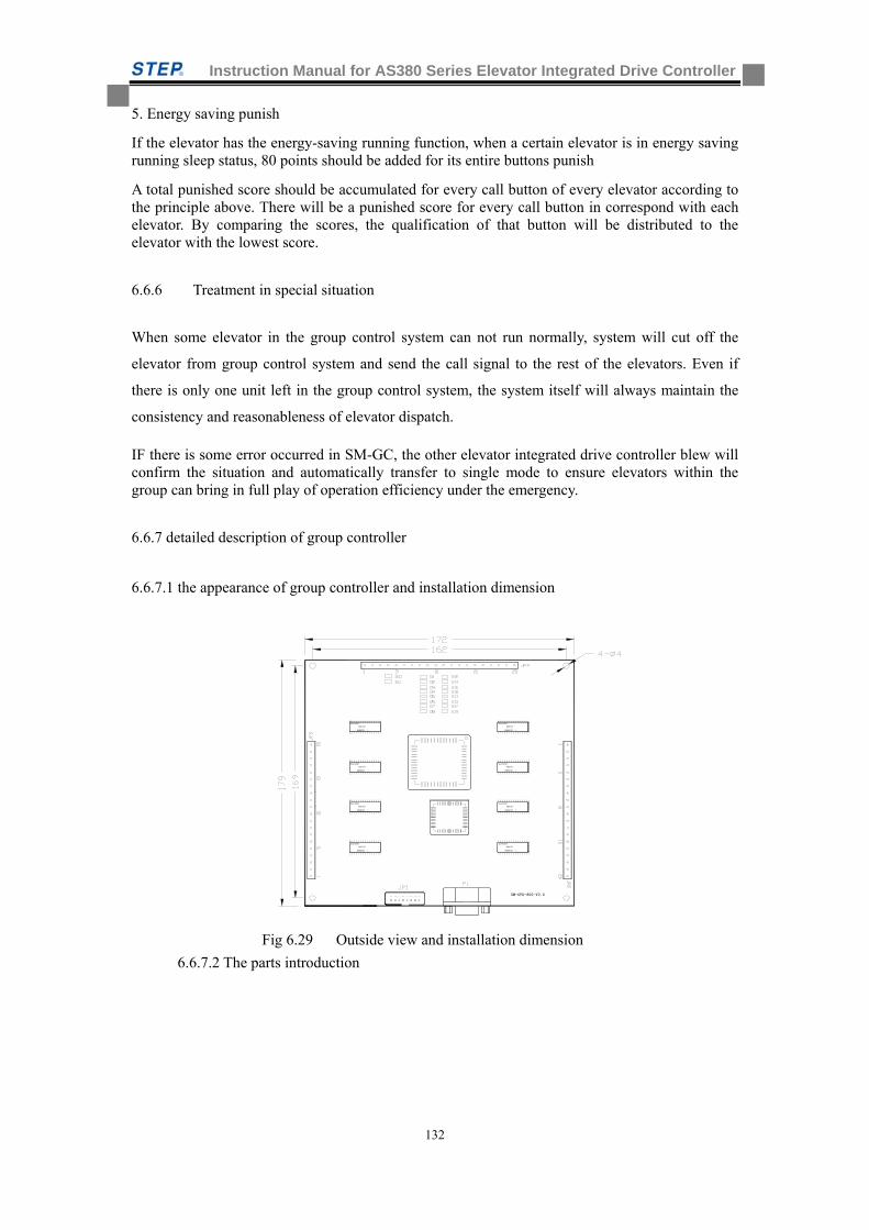
Instruction Manual for AS380 Series Elevator Integrated Drive Controller
132
5. Energy saving punish
If the elevator has the energy-saving running function, when a certain elevator is in energy saving running sleep status, 80 points should be added for its entire buttons punish
A total punished score should be accumulated for every call button of every elevator according to the principle above. There will be a punished score for every call button in correspond with each elevator. By comparing the scores, the qualification of that button will be distributed to the elevator with the lowest score.
6.6.6 Treatment in special situation
When some elevator in the group control system can not run normally, system will cut off the
elevator from group control system and send the call signal to the rest of the elevators. Even if
there is only one unit left in the group control system, the system itself will always maintain the
consistency and reasonableness of elevator dispatch.
IF there is some error occurred in SM-GC, the other elevator integrated drive controller blew will confirm the situation and automatically transfer to single mode to ensure elevators within the group can bring in full play of operation efficiency under the emergency.
6.6.7 detailed description of group controller
6.6.7.1 the appearance of group controller and installation dimension
Fig 6.29 Outside view and installation dimension
6.6.7.2 The parts introduction
SJAI000T
HSHO032 1
SJAI000T
HSHO032 1
KOV747
KOV747
SJAI000T
HSHO032 1
HSHO032 1
SJAI000T
KOV747
KOV747
SM-CPU-800-V2.0
HSHO032 1
SJAI000T
KOV747
KOV747
HSHO032 1
SJAI000T
HSHO032 1
SJAI000T
KOV747
HSHO032 1
SJAI000T
KOV747
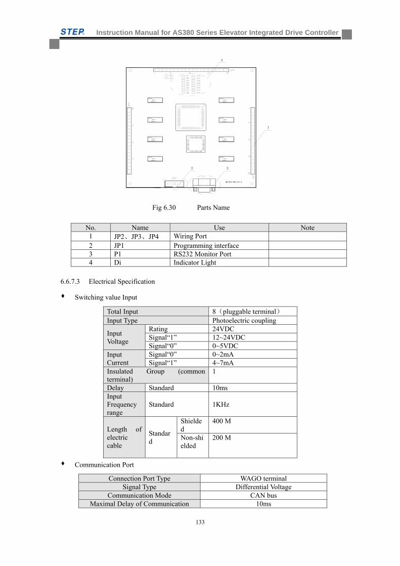
Instruction Manual for AS380 Series Elevator Integrated Drive Controller
133
Fig 6.30 Parts Name
No. Name Use Note 1 JP2、JP3、JP4 Wiring Port 2 JP1 Programming interface 3 P1 RS232 Monitor Port 4 Di Indicator Light
6.6.7.3 Electrical Specification
Switching value Input
Total Input 8(pluggable terminal) Input Type Photoelectric coupling
Input Voltage
Rating 24VDC Signal“1” 12~24VDC Signal“0” 0~5VDC
Input Current
Signal“0” 0~2mA Signal“1” 4~7mA
Insulated Group (common terminal)
1
Delay Standard 10ms Input Frequency range
Standard 1KHz
Length of electric cable
Standard
Shielded
400 M
Non-shielded
200 M
Communication Port
Connection Port Type WAGO terminal Signal Type Differential Voltage
Communication Mode CAN bus Maximal Delay of Communication 10ms
SM-CPU-800-V2.0
HSHO032 1
KOV747
KOV747
HSHO032 1
HSHO032 1
KOV747
KOV747
HSHO032 1
KOV747
HSHO032 1
SJAI000T
KOV747
HSHO032 1
SJAI000T
2
SJAI000T
SJAI000T
KOV747
HSHO032 1
SJAI000T
HSHO032 1
KOV747
SJAI000T
SJAI000T
SJAI000T
4
1
3
Instruction Manual for AS380 Series Elevator Integrated Drive Controller
134
6.6.7.4 Input and Output Interface Definition
The Definition of PortJP2
Pin Port Name
JP2-1 Void
JP2-2 TXA4- Communication signal negative terminal of elevator No.4 in the group control system
JP2-3 TXA4+ Communication signal positive terminal of elevator No.4 in the group control system
JP2-4 TXV4- Power supply negative terminal of elevator No.4 in the group control system
JP2-5 TXV4+ Power supply positive terminal of elevator No.4 in the group control system
JP2-6 Void
JP2-7 TXA3- Communication signal negative terminal of elevator No.3 in the group control system
JP2-8 TXA3+ Communication signal positive terminal of elevator No.3 in the group control system
JP2-9 TXV3- Power supply negative terminal of elevator No.3 in the group control system
JP2-10 TXV3+ Power supply positive terminal of elevator No.3 in the group control system
JP2-11 void
JP2-12 TXA2- Communication signal negative terminal of elevator No.2 in the group control system
JP2-13 TXA2+ Communication signal positive terminal of elevator No.2 in the group control system
JP2-14 TXV2- Power supply negative terminal of elevator No.2 in the group control system
JP2-15 TXV2+ Power supply positive terminal of elevator No.2 in the group control system
JP2-16 Void
JP2-17 TXA1- Communication signal negative terminal of elevator No.1 in the group control system
JP2-18 TXA1+ Communication signal positive terminal of elevator No.1 in the group control system
JP2-19 TXV1- Power supply negative terminal of elevator No.1 in the group control system
JP2-20 TXV1+ Power supply positive terminal of elevator No.1 in the group control system
Definition of Port JP3
Pin Port Name
JP3-1 Void
JP3-2 TXA4- Communication signal negative terminal of elevator No.8 in the group control system
JP3-3 TXA4+ Communication signal positive terminal of elevator No.8 in the group control system
JP3-4 TXV4- Power supply negative terminal of elevator No.8 in the group control system
JP3-5 TXV4+ Power supply positive terminal of elevator No.8 in the group control system
JP3-6 Void
JP3-7 TXA3- Communication signal negative terminal of elevator No.7 in the group control system
JP3-8 TXA3+ Communication signal positive terminal of elevator No.7 in the group control system
JP3-9 TXV3- Power supply negative terminal of elevator No.7 in the group control system
JP3-10 TXV3+ Power supply positive terminal of elevator No.7 in the group control system
JP3-11 Void
JP3-12 TXA2- Communication signal negative terminal of elevator No.6 in the group control system
JP3-13 TXA2+ Communication signal positive terminal of elevator No.6 in the group control system
JP3-14 TXV2- Power supply negative terminal of elevator No.6 in the group control system
JP3-15 TXV2+ Power supply positive terminal of elevator No.6 in the group control system
JP3-16 Void
JP3-17 TXA1- Communication signal negative terminal of elevator No.5 in the group control system
JP3-18 TXA1+ Communication signal positive terminal of elevator No.5 in the group control system
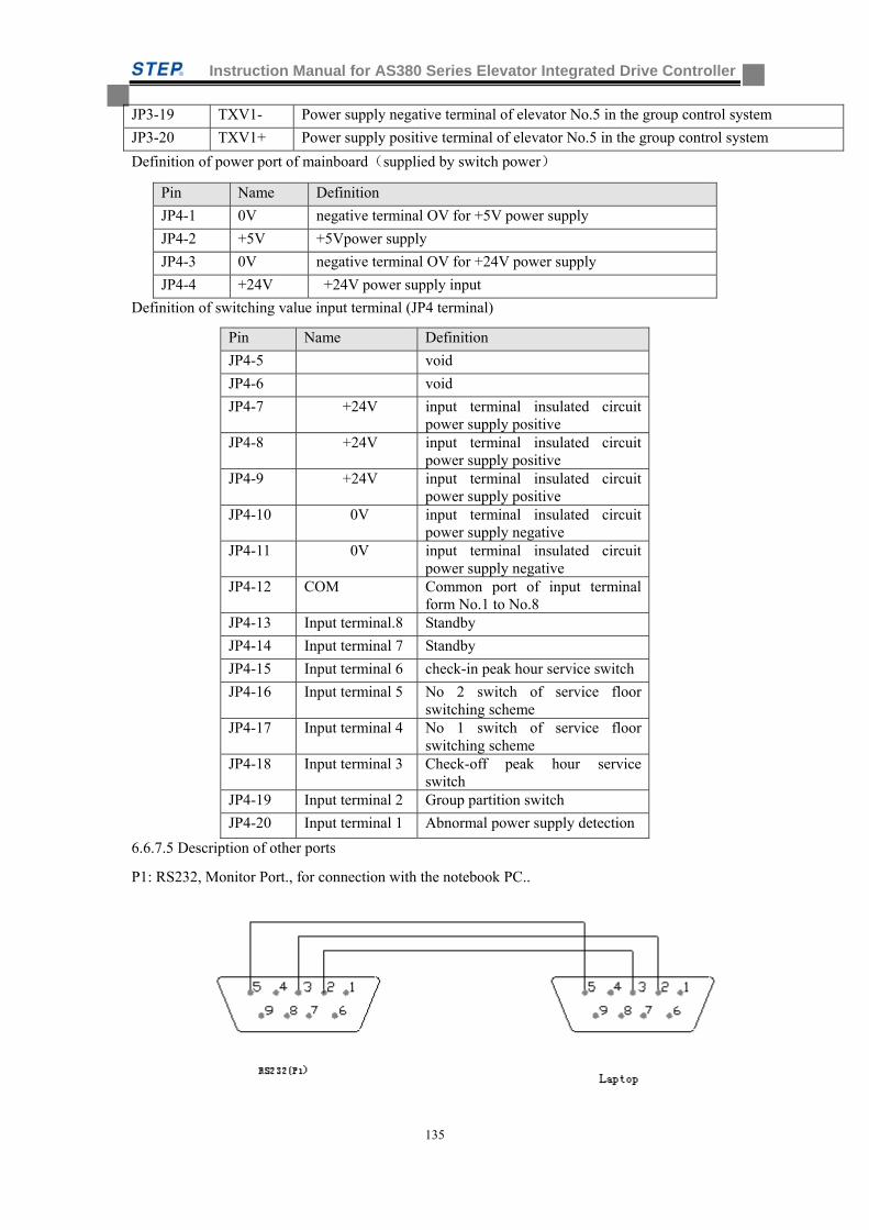
Instruction Manual for AS380 Series Elevator Integrated Drive Controller
135
JP3-19 TXV1- Power supply negative terminal of elevator No.5 in the group control system
JP3-20 TXV1+ Power supply positive terminal of elevator No.5 in the group control system
Definition of power port of mainboard(supplied by switch power)
Pin Name Definition
JP4-1 0V negative terminal OV for +5V power supply
JP4-2 +5V +5Vpower supply
JP4-3 0V negative terminal OV for +24V power supply
JP4-4 +24V +24V power supply input
Definition of switching value input terminal (JP4 terminal)
Pin Name Definition
JP4-5 void
JP4-6 void
JP4-7 +24V input terminal insulated circuit power supply positive
JP4-8 +24V input terminal insulated circuit power supply positive
JP4-9 +24V input terminal insulated circuit power supply positive
JP4-10 0V input terminal insulated circuit power supply negative
JP4-11 0V input terminal insulated circuit power supply negative
JP4-12 COM Common port of input terminal form No.1 to No.8
JP4-13 Input terminal.8 Standby
JP4-14 Input terminal 7 Standby
JP4-15 Input terminal 6 check-in peak hour service switch
JP4-16 Input terminal 5 No 2 switch of service floor switching scheme
JP4-17 Input terminal 4 No 1 switch of service floor switching scheme
JP4-18 Input terminal 3 Check-off peak hour service switch
JP4-19 Input terminal 2 Group partition switch
JP4-20 Input terminal 1 Abnormal power supply detection
6.6.7.5 Description of other ports
P1: RS232, Monitor Port., for connection with the notebook PC..
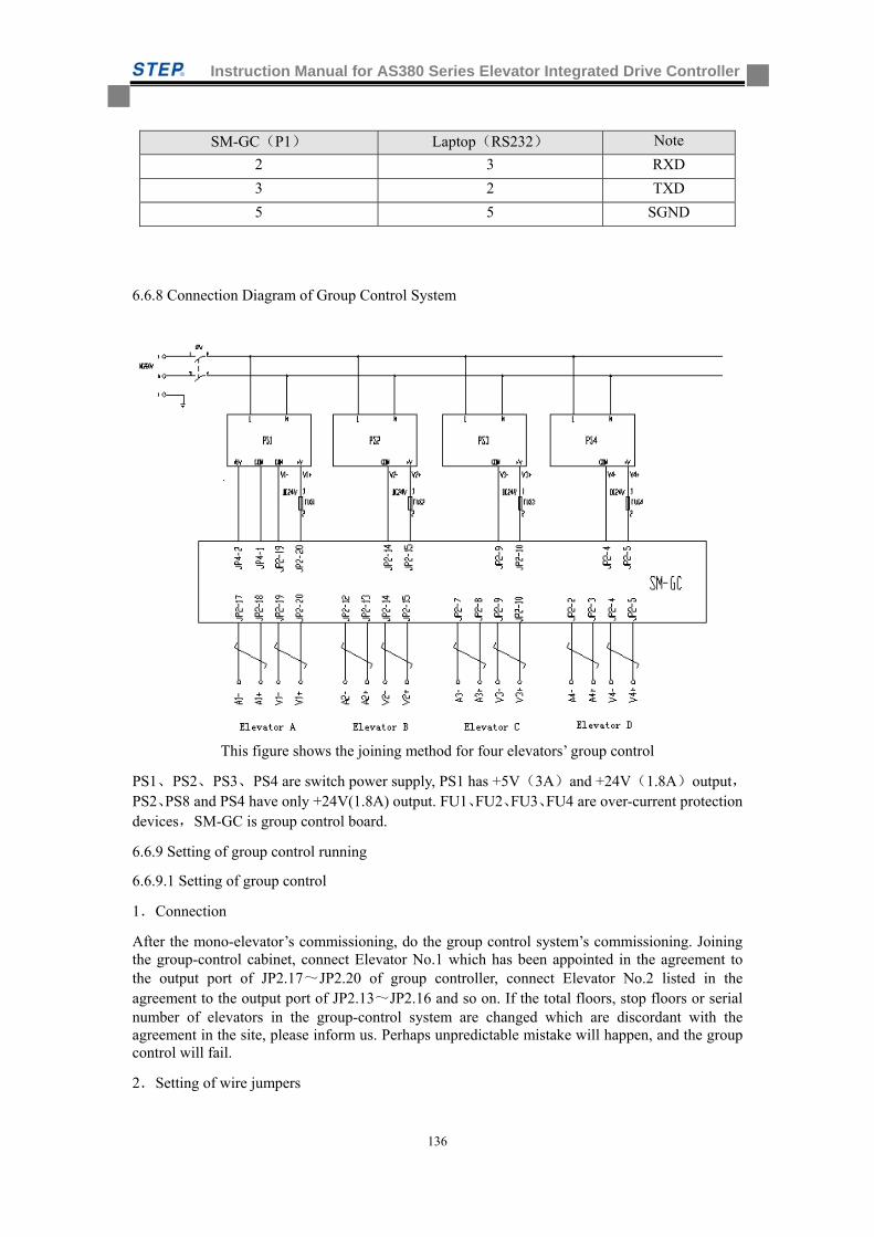
Instruction Manual for AS380 Series Elevator Integrated Drive Controller
136
6.6.8 Connection Diagram of Group Control System
This figure shows the joining method for four elevators’ group control
PS1、PS2、PS3、PS4 are switch power supply, PS1 has +5V(3A)and +24V(1.8A)output,PS2、PS8 and PS4 have only +24V(1.8A) output. FU1、FU2、FU3、FU4 are over-current protection devices,SM-GC is group control board.
6.6.9 Setting of group control running
6.6.9.1 Setting of group control
1.Connection
After the mono-elevator’s commissioning, do the group control system’s commissioning. Joining the group-control cabinet, connect Elevator No.1 which has been appointed in the agreement to the output port of JP2.17~JP2.20 of group controller, connect Elevator No.2 listed in the agreement to the output port of JP2.13~JP2.16 and so on. If the total floors, stop floors or serial number of elevators in the group-control system are changed which are discordant with the agreement in the site, please inform us. Perhaps unpredictable mistake will happen, and the group control will fail.
2.Setting of wire jumpers
SM-GC(P1) Laptop(RS232) Note
2 3 RXD
3 2 TXD
5 5 SGND
Instruction Manual for AS380 Series Elevator Integrated Drive Controller
137
Please connect ‘J1’in the control board with wire jumper before group controlling so as to bridge terminal resistor of two serial communication wire TXA+ , TXA-.
3.Measurement of resistance
After setting the wire jumpers, please use an universal meter to measure the value of the terminal resistance for the future commissioning.
The resistance value of JP5.4 and JP5.5 in the main control board is about 60ohm, if the value is not within this limit, please check the wire jumper is in position or not, the shielded cable is good and plug in the control board is reliable.
4.Manu Setting
Before debugging the group-control system, please make sure that each and every elevator is in normal state, then link to the group control system and start the system commissioning by setting Parameter “Group Mode” of all the elevators to 2 firstly.
6.7.10 Instruction for the group-control parameter setting programming
1. Basic instruction
This program is used for setting the parameter in the group-control CPU board. Connecting computer and group-control CPU board with standard RS232 communication wire set the parameter in computer. The DC5V power supply must be connected to the group control CPU board when in operation. Please take reference to the connection diagram of group control board for the wiring.
2. Installation of program
This program can run directly from CD without installation, or copy to the any folder in an pc for running. In the CD Rom we supplied for client, there are two files GROUPSET.EXE and MSCOMM32.OCX. GROUPSET.EXE is a setting file and MSCOMM32.OCX is a control file. If in your computer there is not file MSCOMM32.OCX, file GROUPSET.EXE is not able to run correctly.
Please do following steps to setup MSCOMM32.OCX:
Copy file Mscomm32.ocx form CD Rom to directory SYSTEM of Windows in your computer, open Run Dialog, click browsing button, select file Regsvr32.exe in the directory SYSTEM of Windows, click Open button, input MScomm32.ocx after Regsvr32.exe and click OK button, then run register program. After running the program a dialogue box displays, click OK button and restart the monitor program.
This program demands the display resolution of your computer to 1024*768
3. Running the setting program
Double click the file GROUPSET.EXE, the main interface of the program is displayed. click Set Button to enter the parameter-setting interface.
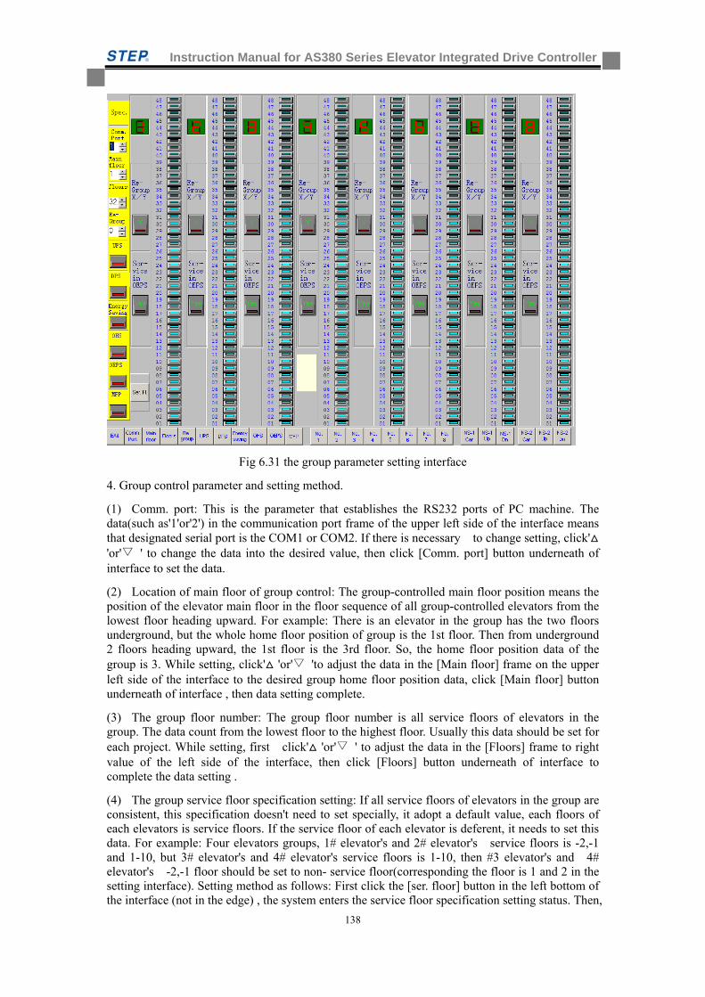
Instruction Manual for AS380 Series Elevator Integrated Drive Controller
138
Fig 6.31 the group parameter setting interface
4. Group control parameter and setting method.
(1) Comm. port: This is the parameter that establishes the RS232 ports of PC machine. The data(such as'1'or'2') in the communication port frame of the upper left side of the interface means that designated serial port is the COM1 or COM2. If there is necessary to change setting, click' 'or' ' to change the data into the desired value, then click [Comm. port] button underneath of interface to set the data.
(2) Location of main floor of group control: The group-controlled main floor position means the position of the elevator main floor in the floor sequence of all group-controlled elevators from the lowest floor heading upward. For example: There is an elevator in the group has the two floors underground, but the whole home floor position of group is the 1st floor. Then from underground 2 floors heading upward, the 1st floor is the 3rd floor. So, the home floor position data of the group is 3. While setting, click' 'or' 'to adjust the data in the [Main floor] frame on the upper left side of the interface to the desired group home floor position data, click [Main floor] button underneath of interface , then data setting complete.
(3) The group floor number: The group floor number is all service floors of elevators in the group. The data count from the lowest floor to the highest floor. Usually this data should be set for each project. While setting, first click' 'or' ' to adjust the data in the [Floors] frame to right value of the left side of the interface, then click [Floors] button underneath of interface to complete the data setting .
(4) The group service floor specification setting: If all service floors of elevators in the group are consistent, this specification doesn't need to set specially, it adopt a default value, each floors of each elevators is service floors. If the service floor of each elevator is deferent, it needs to set this data. For example: Four elevators groups, 1# elevator's and 2# elevator's service floors is -2,-1 and 1-10, but 3# elevator's and 4# elevator's service floors is 1-10, then #3 elevator's and 4# elevator's -2,-1 floor should be set to non- service floor(corresponding the floor is 1 and 2 in the setting interface). Setting method as follows: First click the [ser. floor] button in the left bottom of the interface (not in the edge) , the system enters the service floor specification setting status. Then,
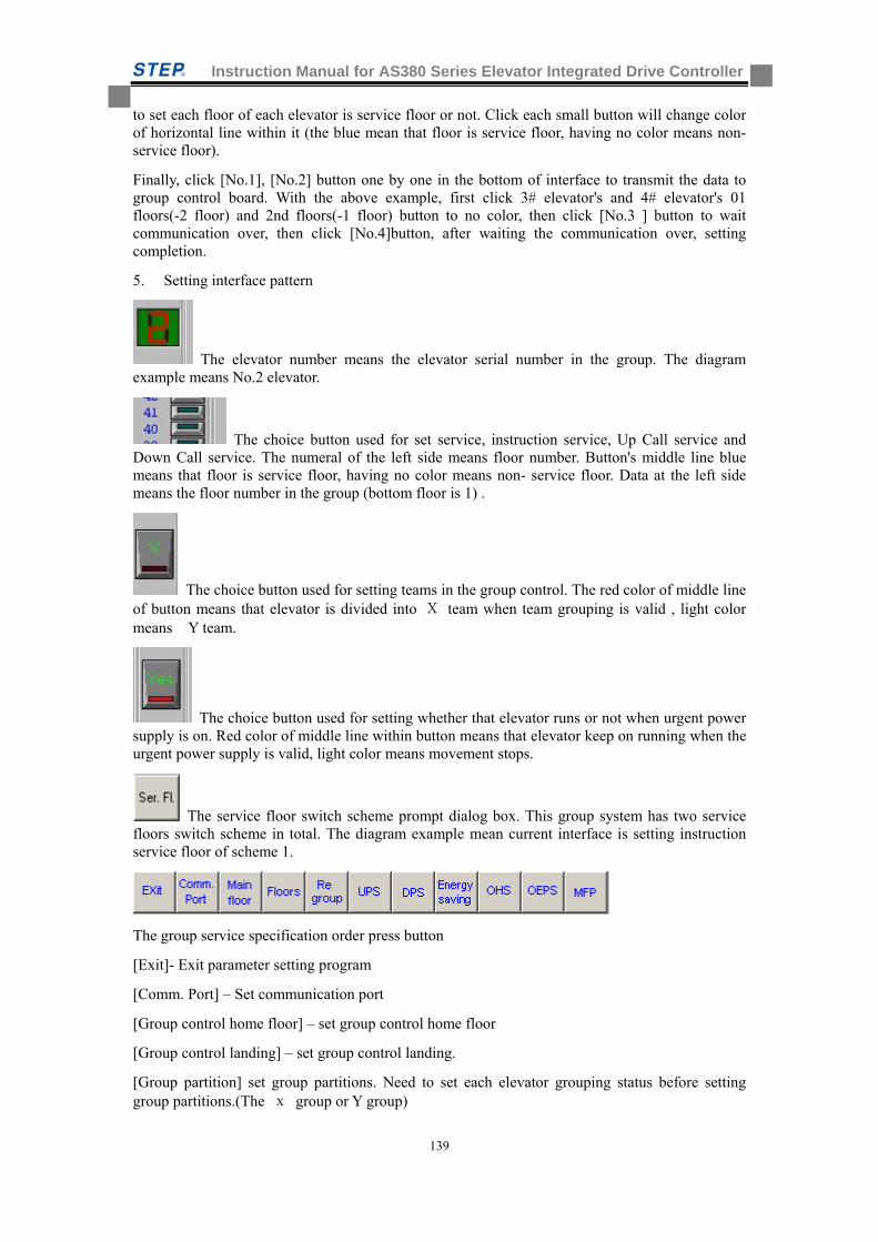
Instruction Manual for AS380 Series Elevator Integrated Drive Controller
139
to set each floor of each elevator is service floor or not. Click each small button will change color of horizontal line within it (the blue mean that floor is service floor, having no color means non- service floor).
Finally, click [No.1], [No.2] button one by one in the bottom of interface to transmit the data to group control board. With the above example, first click 3# elevator's and 4# elevator's 01 floors(-2 floor) and 2nd floors(-1 floor) button to no color, then click [No.3 ] button to wait communication over, then click [No.4]button, after waiting the communication over, setting completion.
5. Setting interface pattern
The elevator number means the elevator serial number in the group. The diagram example means No.2 elevator.
The choice button used for set service, instruction service, Up Call service and Down Call service. The numeral of the left side means floor number. Button's middle line blue means that floor is service floor, having no color means non- service floor. Data at the left side means the floor number in the group (bottom floor is 1) .
The choice button used for setting teams in the group control. The red color of middle line of button means that elevator is divided into X team when team grouping is valid , light color means Y team.
The choice button used for setting whether that elevator runs or not when urgent power supply is on. Red color of middle line within button means that elevator keep on running when the urgent power supply is valid, light color means movement stops.
The service floor switch scheme prompt dialog box. This group system has two service floors switch scheme in total. The diagram example mean current interface is setting instruction service floor of scheme 1.
The group service specification order press button
[Exit]- Exit parameter setting program
[Comm. Port] – Set communication port
[Group control home floor] – set group control home floor
[Group control landing] – set group control landing.
[Group partition] set group partitions. Need to set each elevator grouping status before setting group partitions.(The x group or Y group)
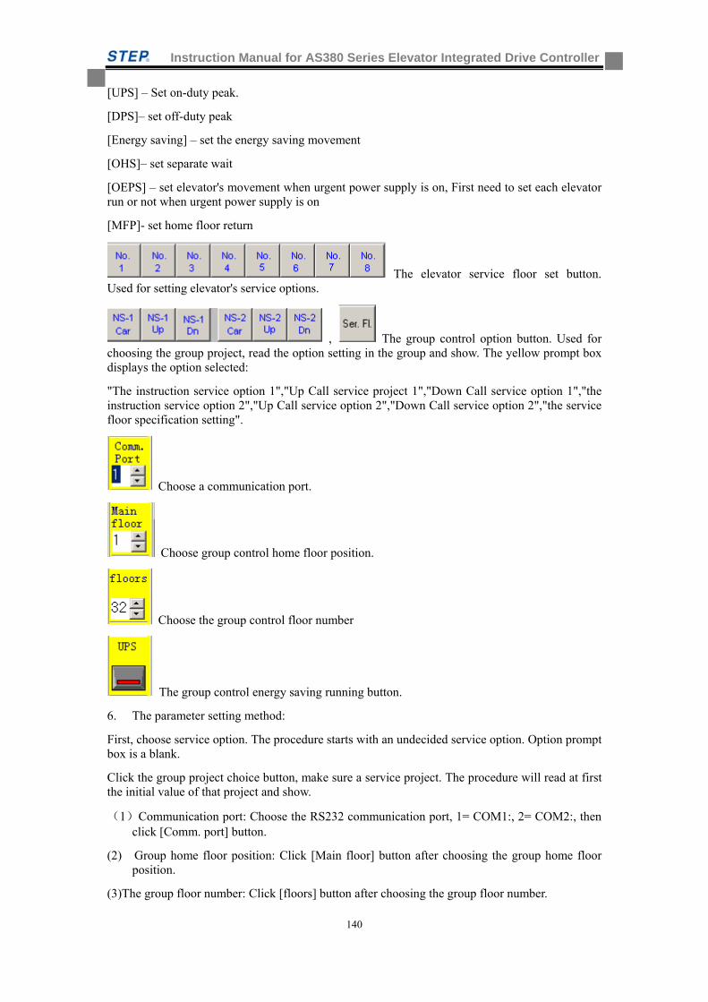
Instruction Manual for AS380 Series Elevator Integrated Drive Controller
140
[UPS] – Set on-duty peak.
[DPS]– set off-duty peak
[Energy saving] – set the energy saving movement
[OHS]– set separate wait
[OEPS] – set elevator's movement when urgent power supply is on, First need to set each elevator run or not when urgent power supply is on
[MFP]- set home floor return
The elevator service floor set button. Used for setting elevator's service options.
, The group control option button. Used for choosing the group project, read the option setting in the group and show. The yellow prompt box displays the option selected:
"The instruction service option 1","Up Call service project 1","Down Call service option 1","the instruction service option 2","Up Call service option 2","Down Call service option 2","the service floor specification setting".
Choose a communication port.
Choose group control home floor position.
Choose the group control floor number
The group control energy saving running button.
6. The parameter setting method:
First, choose service option. The procedure starts with an undecided service option. Option prompt box is a blank.
Click the group project choice button, make sure a service project. The procedure will read at first the initial value of that project and show.
(1)Communication port: Choose the RS232 communication port, 1= COM1:, 2= COM2:, then click [Comm. port] button.
(2) Group home floor position: Click [Main floor] button after choosing the group home floor position.
(3)The group floor number: Click [floors] button after choosing the group floor number.
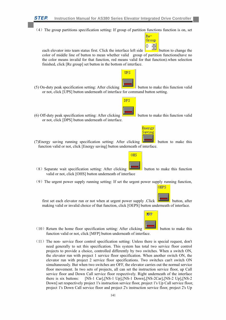
Instruction Manual for AS380 Series Elevator Integrated Drive Controller
141
(4)The group partitions specification setting: If group of partition functions function is on, set
each elevator into team status first. Click the interface left side button to change the color of middle line of button to mean whether valid group of partition functions(have no the color means invalid for that function, red means valid for that function).when selection finished, click [Re group] set button in the bottom of interface.
(5) On-duty peak specification setting: After clicking button to make this function valid or not, click [UPS] button underneath of interface for command button setting.
(6) Off-duty peak specification setting: After clicking button to make this function valid or not, click [DPS] button underneath of interface.
(7)Energy saving running specification setting: After clicking button to make this function valid or not, click [Energy saving] button underneath of interface.
(8)Separate wait specification setting: After clicking button to make this function valid or not, click [OHS] button underneath of interface
(9)The urgent power supply running setting: If set the urgent power supply running function,
first set each elevator run or not when at urgent power supply .Click button, after making valid or invalid choice of that function, click [OEPS] button underneath of interface.
(10)Return the home floor specification setting: After clicking button to make this function valid or not, click [MFP] button underneath of interface.
(11)The non- service floor control specification setting: Unless there is special request, don't need generally to set this specification. This system has total two service floor control projects to provide a choice, controlled differently by two switches. When a switch ON, the elevator run with project 1 service floor specification. When another switch ON, the elevator run with project 2 service floor specifications. Two switches can't switch ON simultaneously. But when two switches are OFF, the elevator carries out the normal service floor movement. In two sets of projects, all can set the instruction service floor, up Call service floor and Down Call service floor respectively. Right underneath of the interface there is six buttons: [NS-1 Car],[NS-1 Up],[NS-1 Down],[NS-2Car],[NS-2 Up],[NS-2 Down] set respectively project 1's instruction service floor, project 1's Up Call service floor, project 1's Down Call service floor and project 2's instruction service floor, project 2's Up
Instruction Manual for AS380 Series Elevator Integrated Drive Controller
142
Call service floor, project 2's Down Call service floor. Its setting method is same with (4) the group service floor specification setting.
(12) When group partition each elevator partition set: Usually this specification doesn't need setting, but if a group of partition functions exist, it has to carry out this setting. Click button in under [Re. group X/Y] in the frame of elevator in the interface to change middle line's color within button, it will change the elevator's partition, red color means to divide to the X set, having no color means to divide to the Y set. After that button is set, click [Re. group] button underneath the interface.
(13) Whether continued to run specification setting or not when urgent power supply is on: Usually this specification doesn't need to be set, but if have urgent power supply run function, have to carry on this setting. Click button underneath [OEPS] of elevator's frame in the interface, to change the color of middle line of button, the red mean this set elevator continues to run, having no color means stop running. After setting that button, click [OEPS] button underneath the interface.
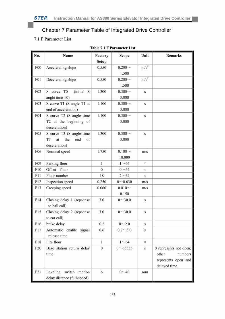
Instruction Manual for AS380 Series Elevator Integrated Drive Controller
143
Chapter 7 Parameter Table of Integrated Drive Controller
7.1 F Parameter List
Table 7.1 F Parameter List
No. Name Factory
Setup
Scope Unit Remarks
F00 Accelerating slope 0.550 0.200~
1.500
m/s2
F01 Decelerating slope 0.550 0.200~
1.500
m/s2
F02 S curve T0 (initial S
angle time T0)
1.300 0.300~
3.000
s
F03 S curve T1 (S angle T1 at
end of acceleration)
1.100 0.300~
3.000
s
F04 S curve T2 (S angle time
T2 at the beginning of
deceleration)
1.100 0.300~
3.000
s
F05 S curve T3 (S angle time
T3 at the end of
deceleration)
1.300 0.300~
3.000
s
F06 Nominal speed 1.750 0.100~
10.000
m/s
F09 Parking floor 1 1~64 ×
F10 Offset floor 0 0~64 ×
F11 Floor number 18 2~64 ×
F12 Inspection speed 0.250 0~0.630 m/s
F13 Creeping speed 0.060 0.010~
0.150
m/s
F14 Closing delay 1 (repsonse
to hall call)
3.0 0~30.0 s
F15 Closing delay 2 (repsonse
to car call)
3.0 0~30.0 s
F16 brake delay 0.2 0~2.0 s
F17 Automatic enable signal
release time
0.6 0.2~3.0 s
F18 Fire floor 1 1~64 ×
F20 Base station return delay
time
0 0~65535 s 0 represents not open;
other numbers
represents open and
delayed time.
F21 Leveling switch motion
delay distance (full-speed)
6 0~40 mm

Instruction Manual for AS380 Series Elevator Integrated Drive Controller
144
F22 Single and Duplex return
to base station
1 1~64 ×
F23 Group control mode 0 0~3 ×
F25 Input type 1 (normal open
or close setup for X0~
X15 input point)
819 0~65535
×
F26 Input type 2 (normal open
or close setup for X16~
X25 input point)
2 0~65535
×
F27 Elevator car board input
type (normal open or close
setup for GX0 ~ GX15
input point)
0 0~65535
×
F28 Car roof input type
(normal open or close
setup for HX0 ~ HX15
input point)
327 0~65535
×
F29 Service floor 1 (Set up if
1~16 floors are secure)
65535 0~65535 ×
F30 Service floor 2 (Set up if
17~32 floors are secure)
65535 0~65535 ×
F31 Service floor 3 (Set up if
33~48 floors are secure)
65535 0~65535 ×
F190 Service floor 4 (Set up if
49~64 floors are secure)
65535 0~65535 ×
F33 Auomatic operation
interval for test run
5 0~60 s
F34 Automatic operation times
for test run.
0 0~65535

Instruction Manual for AS380 Series Elevator Integrated Drive Controller
145
F35
Firefighting switch input
definition and firefighting
mode selection
0 0~65535 ×
Bit0: 0: ordinary
firefighting, 1:
Schindler fire mode
Bit1: 0: fireman
switch without lift car
board; 1: fireman
switch with lift car
board
Bit2: 0: ordinary
firefighting signal
display; 1: Shandong
firefighting signal
display
Bit3: 0: Motherboard
X15 input for
firefighting return; 1:
Motherboard X15
input for fireman
switch
F36 Band-type Brake switch
detection mode
0 0~2 ×
F40 Weight data bias 48 0~100 %
F41 Weighter study and
parameter setup
command.
0 0/1/2/
10/20/30
/40/50/
60
×
F43 Buzzing/flashing function
selection for attendant
status call
3 0~65535 × .
F44 Serial communication
address (255 for
non-monitor)
255 0~255 ×
F49 Emergency leveling
orientation mode
0 0~2
F50 Front door opening
permission 1 (opening
setup value for 1 ~ 16
floors)
65535 0~65535 ×
F51 Front door opening
permission 2 (opening
setup value for 17 ~ 32
floors)
65535 0~65535 ×

Instruction Manual for AS380 Series Elevator Integrated Drive Controller
146
F52 Front door opening
permission 3 (opening
setup value for 33 ~ 48
floors)
65535 0~65535 ×
F191 Front door opening
permission 4 (opening
setup value for 49 ~ 64
floors)
65535 0~65535 ×
F53 Rear door opening
permission 1 (opening
setup value for 1 ~ 16
floors)
0 0~65535 ×
F54 Rear door opening
permission 2 (opening
setup value for 17 ~ 32
floors)
0 0~65535 ×
F55 Rear door opening
permission 3 (opening
setup value for 33 ~ 48
floors)
0 0~65535 ×
F192 Rear door opening
permission 4 (opening
setup value for 49 ~ 64
floors)
0 0~65535 ×
F56 Up leveling adjustment (50
to refernece value)
50 0~240 mm
F57 Down leveling adjustment
(50 to refernece value)
50 0~240 mm
F59 Zero speed brake delay 0 0~10.00 0.01s
F61 Arrival distance by arrival
gong
1200 0~4000 mm
F62 Anti-slipping limit time 32 20~45 s
F65 Base electrode lock mode 0 0~1 × 0: No base lock, 1:
output contactor off,
immediate lock
F66 With or whithout upper
and lower limt
0 0-1 0:no
1:yes
F67 With or whithout
entension board
0 0-1 0:no
1:yes
F70 Light load uplink gain 100 0-300 %
F71 Light load lowlink gain 100 0-300 %
F72 Heavy load uplink gain 100 0-300 %
F73 Heavy load lowlink gain 100 0-300 %
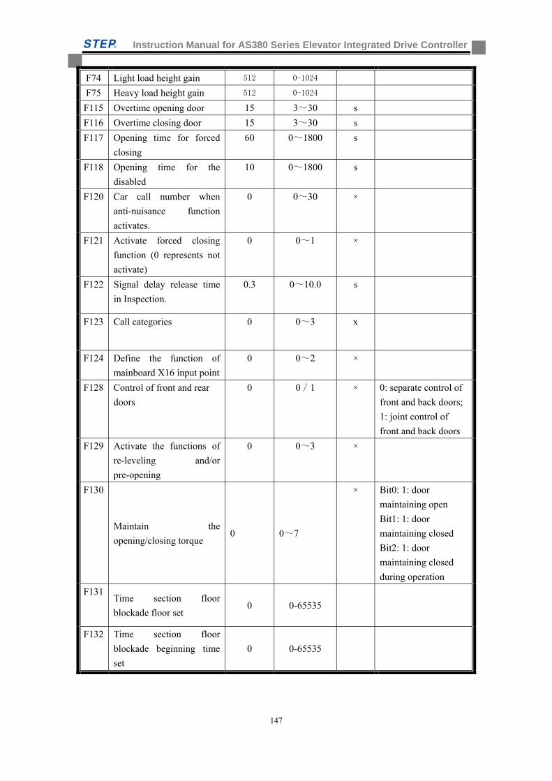
Instruction Manual for AS380 Series Elevator Integrated Drive Controller
147
F74 Light load height gain 512 0-1024
F75 Heavy load height gain 512 0-1024
F115 Overtime opening door 15 3~30 s
F116 Overtime closing door 15 3~30 s
F117 Opening time for forced
closing
60 0~1800 s
F118 Opening time for the
disabled
10 0~1800 s
F120 Car call number when
anti-nuisance function
activates.
0 0~30 ×
F121 Activate forced closing
function (0 represents not
activate)
0 0~1 ×
F122 Signal delay release time
in Inspection.
0.3 0~10.0 s
F123 Call categories 0 0~3 x
F124 Define the function of
mainboard X16 input point
0 0~2 ×
F128 Control of front and rear
doors
0 0/1 × 0: separate control of
front and back doors;
1: joint control of
front and back doors
F129 Activate the functions of
re-leveling and/or
pre-opening
0 0~3 ×
F130
Maintain the
opening/closing torque 0 0~7
× Bit0: 1: door
maintaining open
Bit1: 1: door
maintaining closed
Bit2: 1: door
maintaining closed
during operation
F131 Time section floor
blockade floor set 0 0-65535
F132 Time section floor
blockade beginning time
set
0 0-65535

Instruction Manual for AS380 Series Elevator Integrated Drive Controller
148
F133 Time section floor
blockade closure time set 0 0-65535
F137 Service floor 1 (Floor 1~
16) when NS-SW function
is set.
65535 0~65535 ×
F138 Service floor 2 (Floor 17~
32) when NS-SW function
is set.
65535 0~65535 ×
F139 Service floor 3 (Floor 33~
48) when NS-SW function
is set.
65535 0~65535 ×
F199 Service floor 4 (Floor 49~
64) when NS-SW function
is set.
65535 0~65535 ×
F141 Time of delay release of
the main contactor (after
enabled)
0.50 0.50~10.00 s
F145 Bus voltage gain 100 80~120 %
F146 Position error distance 180 180~1000 mm
F147
Protection of contact
detection 0 0~1
F152 Lighting delay (fans turned
off automatically, delay
lighting)
180 0~65535 S 0: do not turn off the
lights
F153 high-voltage input
detection with or without
hall door lock
1 0/1 × 0: No
1: Yes
F156 With or without lock relay
contact detection
1 0/1 × 0: No
1: Yes
F160 Whether the manual
removal of error
instruction activated
1 0/1 × 0: No
1: Yes
F161 The function of floor
blocking for a time slot 0 0~65535
× Bit0: 1: block
instruction
Bit1: 1: block upward
call
Bit2: 1: block
downward call

Instruction Manual for AS380 Series Elevator Integrated Drive Controller
149
F163 Choose whether the
back-up power continues
running after returning to
the base in case of single
elevator or parallel
connection
0 0/1
×
0: stop running
1: may continue
running
F164 Type of weighing device 99 0~99 × See the manual for
more detailed
explanation
F165 Special control of door
operation
0 0~65535 × Bit0: 1: door closed
during Ispection
Bit1: 1: door closed
during debug running
Bit2: 1: door opened
at the base station for
the elevator
Bit3: 1: whether to
open the door by LED
operator
F168 Elevator No. with IC card
service
0 0~65535 ×
F169 Selection of upward and
downward callus by IC
card
0 0~65535 ×
F170 IC card function in the car
corresponding to IC card
swiping need on Floor 1~
16
0 0~65535 ×
F171 IC card function in the car
corresponding to IC card
swiping need on Floor
17~32
0 0~65535 ×
F172 IC card function in the car
corresponding to IC card
swiping need on Floor
33~48
0 0~65535 ×
F175 Creeping speed at startup 0.006 0~0.100 m/s
F180 Speed gain 100.0 0~110.0 %
F181 Elevator No. at mutual
parallel connection mode
0 0~1 ×
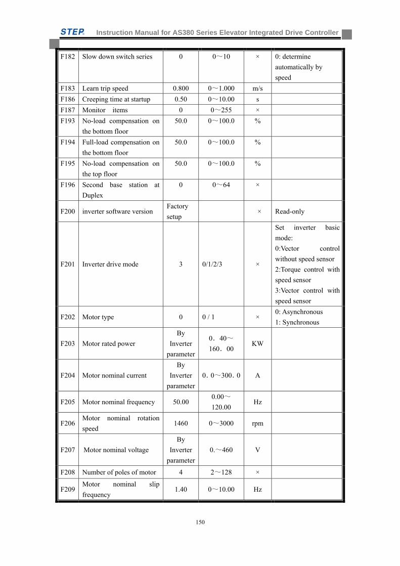
Instruction Manual for AS380 Series Elevator Integrated Drive Controller
150
F182 Slow down switch series 0 0~10 × 0: determine
automatically by
speed
F183 Learn trip speed 0.800 0~1.000 m/s
F186 Creeping time at startup 0.50 0~10.00 s
F187 Monitor items 0 0~255 ×
F193 No-load compensation on
the bottom floor
50.0 0~100.0 %
F194 Full-load compensation on
the bottom floor
50.0 0~100.0 %
F195 No-load compensation on
the top floor
50.0 0~100.0 %
F196 Second base station at
Duplex
0 0~64 ×
F200 inverter software version Factory
setup × Read-only
F201 Inverter drive mode 3 0/1/2/3 ×
Set inverter basic
mode:
0:Vector control
without speed sensor
2:Torque control with
speed sensor
3:Vector control with
speed sensor
F202 Motor type 0 0 / 1 × 0: Asynchronous
1: Synchronous
F203 Motor rated power
By
Inverter
parameter
0.40~
160.00 KW
F204 Motor nominal current
By
Inverter
parameter
0.0~300.0 A
F205 Motor nominal frequency 50.00 0.00~
120.00 Hz
F206 Motor nominal rotation
speed 1460 0~3000 rpm
F207 Motor nominal voltage
By
Inverter
parameter
0.~460 V
F208 Number of poles of motor 4 2~128 ×
F209 Motor nominal slip
frequency 1.40 0~10.00 Hz
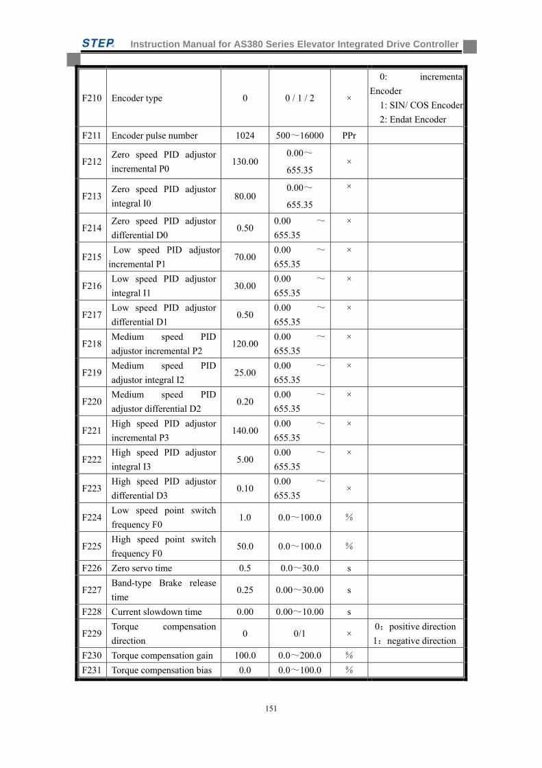
Instruction Manual for AS380 Series Elevator Integrated Drive Controller
151
F210 Encoder type 0 0 / 1 / 2 ×
0: incremental
Encoder
1: SIN/ COS Encoder
2: Endat Encoder
F211 Encoder pulse number 1024 500~16000 PPr
F212 Zero speed PID adjustor
incremental P0 130.00
0.00~
655.35 ×
F213 Zero speed PID adjustor
integral I0 80.00
0.00~
655.35
×
F214 Zero speed PID adjustor
differential D0 0.50
0.00 ~
655.35
×
F215 Low speed PID adjustor
incremental P1 70.00
0.00 ~
655.35
×
F216 Low speed PID adjustor
integral I1 30.00
0.00 ~
655.35
×
F217 Low speed PID adjustor
differential D1 0.50
0.00 ~
655.35
×
F218 Medium speed PID
adjustor incremental P2 120.00
0.00 ~
655.35
×
F219 Medium speed PID
adjustor integral I2 25.00
0.00 ~
655.35
×
F220 Medium speed PID
adjustor differential D2 0.20
0.00 ~
655.35
×
F221 High speed PID adjustor
incremental P3 140.00
0.00 ~
655.35
×
F222 High speed PID adjustor
integral I3 5.00
0.00 ~
655.35
×
F223 High speed PID adjustor
differential D3 0.10
0.00 ~
655.35 ×
F224 Low speed point switch
frequency F0 1.0 0.0~100.0 %
F225 High speed point switch
frequency F0 50.0 0.0~100.0 %
F226 Zero servo time 0.5 0.0~30.0 s
F227 Band-type Brake release
time 0.25 0.00~30.00 s
F228 Current slowdown time 0.00 0.00~10.00 s
F229 Torque compensation
direction 0 0/1 ×
0:positive direction
1:negative direction
F230 Torque compensation gain 100.0 0.0~200.0 %
F231 Torque compensation bias 0.0 0.0~100.0 %
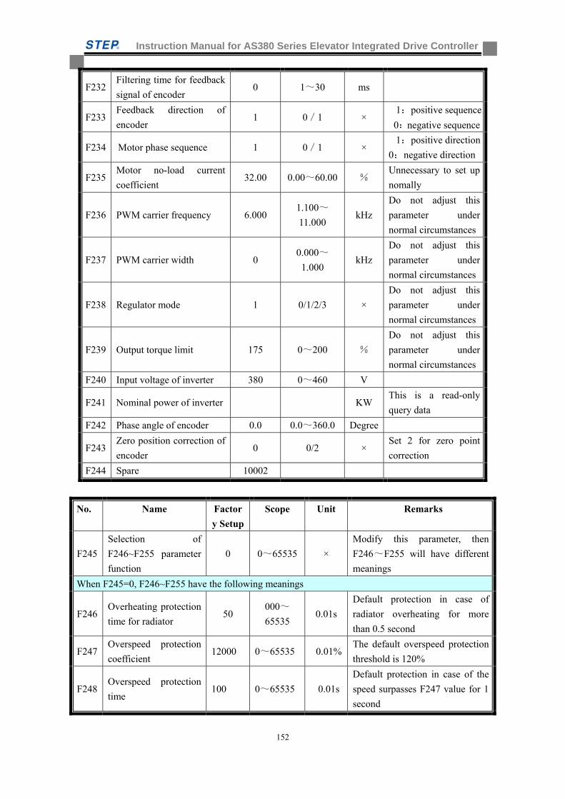
Instruction Manual for AS380 Series Elevator Integrated Drive Controller
152
F232 Filtering time for feedback
signal of encoder 0 1~30 ms
F233 Feedback direction of
encoder 1 0/1 ×
1:positive sequence
0:negative sequence
F234 Motor phase sequence 1 0/1 × 1:positive direction
0:negative direction
F235 Motor no-load current
coefficient 32.00 0.00~60.00 %
Unnecessary to set up
nomally
F236 PWM carrier frequency 6.000 1.100~
11.000 kHz
Do not adjust this
parameter under
normal circumstances
F237 PWM carrier width 0 0.000~
1.000 kHz
Do not adjust this
parameter under
normal circumstances
F238 Regulator mode 1 0/1/2/3 ×
Do not adjust this
parameter under
normal circumstances
F239 Output torque limit 175 0~200 %
Do not adjust this
parameter under
normal circumstances
F240 Input voltage of inverter 380 0~460 V
F241 Nominal power of inverter KW This is a read-only
query data
F242 Phase angle of encoder 0.0 0.0~360.0 Degree
F243 Zero position correction of
encoder 0 0/2 ×
Set 2 for zero point
correction
F244 Spare 10002
No. Name Factor
y Setup
Scope Unit Remarks
F245
Selection of
F246~F255 parameter
function
0 0~65535 ×
Modify this parameter, then
F246~F255 will have different
meanings
When F245=0, F246~F255 have the following meanings
F246 Overheating protection
time for radiator 50
000~
65535 0.01s
Default protection in case of
radiator overheating for more
than 0.5 second
F247 Overspeed protection
coefficient 12000 0~65535 0.01%
The default overspeed protection
threshold is 120%
F248 Overspeed protection
time 100 0~65535 0.01s
Default protection in case of the
speed surpasses F247 value for 1
second
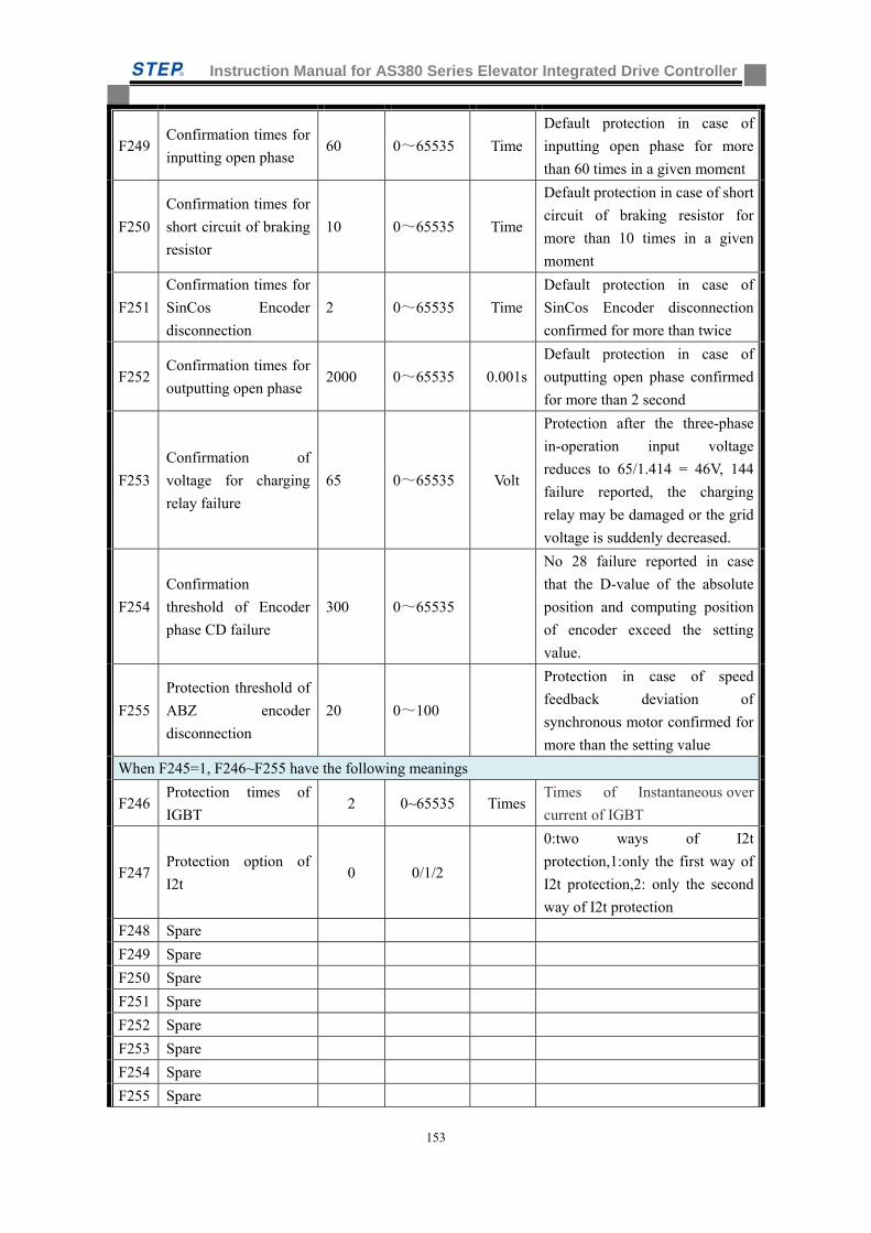
Instruction Manual for AS380 Series Elevator Integrated Drive Controller
153
F249 Confirmation times for
inputting open phase 60 0~65535 Time
Default protection in case of
inputting open phase for more
than 60 times in a given moment
F250
Confirmation times for
short circuit of braking
resistor
10 0~65535 Time
Default protection in case of short
circuit of braking resistor for
more than 10 times in a given
moment
F251
Confirmation times for
SinCos Encoder
disconnection
2 0~65535 Time
Default protection in case of
SinCos Encoder disconnection
confirmed for more than twice
F252 Confirmation times for
outputting open phase 2000 0~65535 0.001s
Default protection in case of
outputting open phase confirmed
for more than 2 second
F253
Confirmation of
voltage for charging
relay failure
65 0~65535 Volt
Protection after the three-phase
in-operation input voltage
reduces to 65/1.414 = 46V, 144
failure reported, the charging
relay may be damaged or the grid
voltage is suddenly decreased.
F254
Confirmation
threshold of Encoder
phase CD failure
300 0~65535
No 28 failure reported in case
that the D-value of the absolute
position and computing position
of encoder exceed the setting
value.
F255
Protection threshold of
ABZ encoder
disconnection
20 0~100
Protection in case of speed
feedback deviation of
synchronous motor confirmed for
more than the setting value
When F245=1, F246~F255 have the following meanings
F246 Protection times of
IGBT 2 0~65535 Times
Times of Instantaneous over
current of IGBT
F247 Protection option of
I2t 0 0/1/2
0:two ways of I2t
protection,1:only the first way of
I2t protection,2: only the second
way of I2t protection
F248 Spare
F249 Spare
F250 Spare
F251 Spare
F252 Spare
F253 Spare
F254 Spare
F255 Spare
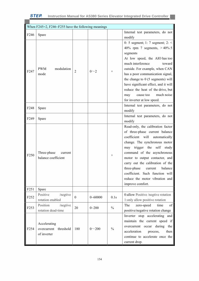
Instruction Manual for AS380 Series Elevator Integrated Drive Controller
154
When F245=2, F246~F255 have the following meanings
F246 Spare Internal test parameters, do not
modify
F247 PWM modulation
mode 2 0~2 ×
0: 5 segment; 1: 7 segment; 2: <
40% rpm 7 segments, > 40% 5
segments
At low speed, the AIO has too
much interference toward
outside. For example, when CAN
has a poor communication signal,
the change to 0 (5 segments) will
have significant effect, and it will
reduce the heat of the drive, but
may cause too much noise
for inverter at low speed.
F248 Spare Internal test parameters, do not
modify
F249 Spare Internal test parameters, do not
modify
F250 Three-phase current
balance coefficient ×
Read-only, the calibration factor
of three-phase current balance
coefficient will automatically
change. The synchronous motor
may trigger the self study
command of the asynchronous
motor to output contactor, and
carry out the calibration of the
three-phase current balance
coefficient. Such function will
reduce the motor vibration and
improve comfort.
F251 Spare
F252 Positive /negtive
rotation enabled 0 0~60000 0.1s
0:allow Positive /negtive rotation
1:only allow positive rotation
F253 Position /negtive
rotation dead-time 20 0~200 %
The zero-speed time of
positive/negative rotation change
F254
Accelerating
overcurrent threshold
of inverter
180 0~200 %
Inverter stop accelerating and
maintain the current speed if
overcurrent occur during the
acceleration process, then
continue to accelerate once the
current drop.

Instruction Manual for AS380 Series Elevator Integrated Drive Controller
155
F255
decelerating
overvoltage threshold
of inverter
750 0~800 V
Inverter stop decelerating and
maintain the current speed if bus
voltage is more than the setting
value during the deceleration
process, then continue to
decelerate once the voltage drop.
When F245=3, F246~F255 have the following meanings
F246 Current loop P 140 35~280 × Current loop Kp (no need to
modify)
F247 Current loop I 100 25~200 × Current loop Ki(no need to
modify)
F248 Current loop D 0 0~200 × Current loop Kd(no need to
modify)
F249 spare ×
F250 spare ×
F251 spare ×
F252 spare ×
F253 Spare
F254 Torque direction 0 0/1 0:positive 1:negtive
F255 Spare
When F245=4, F246~F255 have the following meanings
F246 Software version x Read-only
F247 ID No 0 X Read-only
F248 ID No 1 X Read-only
F249 ID No 2 x Read-only
F250 ID No 3 x Read-only
F251 ID No 4 X Read-only
F252 ID No 5 X Read-only
F253 Inverter rated current 0.1A Read-only
F254 Rated current of
inverter current sensor A Read-only
F255 Motor power
coefficient 200 50~400 %
Set the max power output,
generally do not need to change
When F245=5, F246~F255 have the following meanings
F246 Stator resistor 0.001
ohm
Stator resistor of asynchronous
motor
F247 Rotor resistor 0.001
ohm
Rotor resistor of asynchronous
motor
F248 Stator inductor 0.0001
H
Stator inductor of asynchronous
motor
F249 Rotor inductor 0.0001
H
Rotor inductor of asynchronous
motor
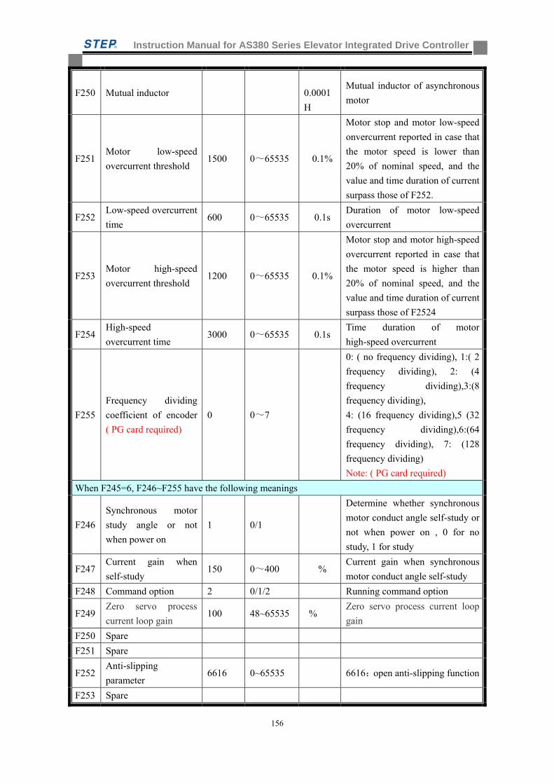
Instruction Manual for AS380 Series Elevator Integrated Drive Controller
156
F250 Mutual inductor
0.0001
H
Mutual inductor of asynchronous
motor
F251 Motor low-speed
overcurrent threshold 1500 0~65535 0.1%
Motor stop and motor low-speed
onvercurrent reported in case that
the motor speed is lower than
20% of nominal speed, and the
value and time duration of current
surpass those of F252.
F252 Low-speed overcurrent
time 600 0~65535 0.1s
Duration of motor low-speed
overcurrent
F253 Motor high-speed
overcurrent threshold 1200 0~65535 0.1%
Motor stop and motor high-speed
overcurrent reported in case that
the motor speed is higher than
20% of nominal speed, and the
value and time duration of current
surpass those of F2524
F254 High-speed
overcurrent time 3000 0~65535 0.1s
Time duration of motor
high-speed overcurrent
F255
Frequency dividing
coefficient of encoder
( PG card required)
0 0~7
0: ( no frequency dividing), 1:( 2
frequency dividing), 2: (4
frequency dividing),3:(8
frequency dividing),
4: (16 frequency dividing),5 (32
frequency dividing),6:(64
frequency dividing), 7: (128
frequency dividing)
Note: ( PG card required)
When F245=6, F246~F255 have the following meanings
F246
Synchronous motor
study angle or not
when power on
1 0/1
Determine whether synchronous
motor conduct angle self-study or
not when power on , 0 for no
study, 1 for study
F247 Current gain when
self-study 150 0~400 %
Current gain when synchronous
motor conduct angle self-study
F248 Command option 2 0/1/2 Running command option
F249 Zero servo process
current loop gain 100 48~65535 %
Zero servo process current loop
gain
F250 Spare
F251 Spare
F252 Anti-slipping
parameter 6616 0~65535 6616:open anti-slipping function
F253 Spare
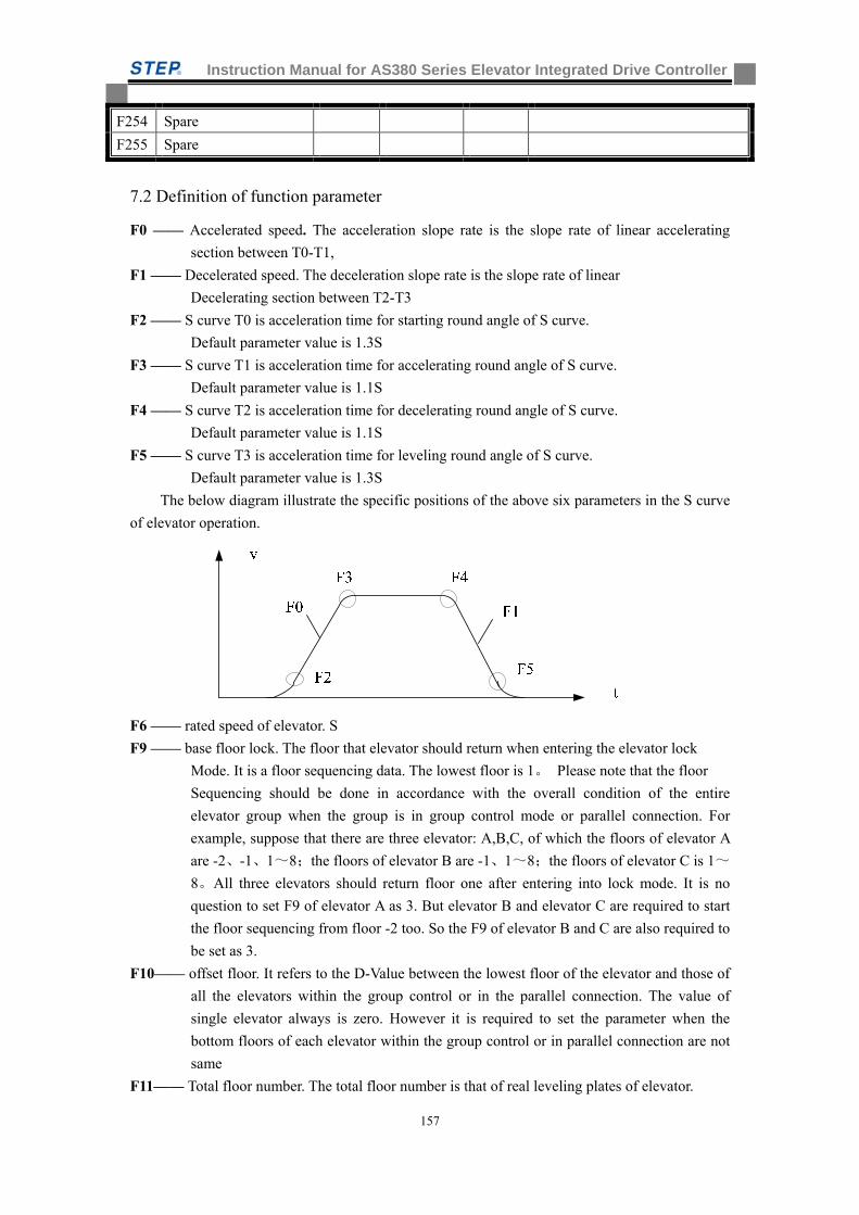
Instruction Manual for AS380 Series Elevator Integrated Drive Controller
157
F254 Spare
F255 Spare
7.2 Definition of function parameter
F0 —— Accelerated speed. The acceleration slope rate is the slope rate of linear accelerating
section between T0-T1,
F1 —— Decelerated speed. The deceleration slope rate is the slope rate of linear
Decelerating section between T2-T3
F2 —— S curve T0 is acceleration time for starting round angle of S curve.
Default parameter value is 1.3S
F3 —— S curve T1 is acceleration time for accelerating round angle of S curve.
Default parameter value is 1.1S
F4 —— S curve T2 is acceleration time for decelerating round angle of S curve.
Default parameter value is 1.1S
F5 —— S curve T3 is acceleration time for leveling round angle of S curve.
Default parameter value is 1.3S
The below diagram illustrate the specific positions of the above six parameters in the S curve
of elevator operation.
F6 —— rated speed of elevator. S
F9 —— base floor lock. The floor that elevator should return when entering the elevator lock
Mode. It is a floor sequencing data. The lowest floor is 1。 Please note that the floor
Sequencing should be done in accordance with the overall condition of the entire
elevator group when the group is in group control mode or parallel connection. For
example, suppose that there are three elevator: A,B,C, of which the floors of elevator A
are -2、-1、1~8;the floors of elevator B are -1、1~8;the floors of elevator C is 1~
8。All three elevators should return floor one after entering into lock mode. It is no
question to set F9 of elevator A as 3. But elevator B and elevator C are required to start
the floor sequencing from floor -2 too. So the F9 of elevator B and C are also required to
be set as 3.
F10—— offset floor. It refers to the D-Value between the lowest floor of the elevator and those of
all the elevators within the group control or in the parallel connection. The value of
single elevator always is zero. However it is required to set the parameter when the
bottom floors of each elevator within the group control or in parallel connection are not
same
F11—— Total floor number. The total floor number is that of real leveling plates of elevator.
Instruction Manual for AS380 Series Elevator Integrated Drive Controller
158
The following is the example explaining the setting method of parameter F10 and F11
Suppose that there are two elevators in parallel connection in a building. Elevator A
serves 15 floors above ground only while Elevator B serves 15 floors above ground and
2 floors underground.
For Elevator A, the total floor number is 15; offset floor is 2; the address of lowest floor
call and registration begin with 3.
For Elevator B, the total floor number is 17; offset floor is 0, the address of lowest floor
call and registration begin with 1.
Note: if the by-pass floors of elevators within the group control or in parallel
connection are different, it is required to artificially make the service floors by
installing the leveling plate to the by-pass floors of those elevators. In this way do
guarantee the same floor sequencing among the elevators within the group control
or in parallel connection.
Example as the following table
Table 7.2 example for F10 and F11 parameter setting
As show in the above table, Elevator B must install a leveling plate at the by-pass
position of second floor to keep its floor number as same as Elevator A.
For elevator A, the total floor number is 4; floor offset is 1; the address of first floor call and
registration begin with 2. Display setting: first floor=70; second floor=2;
Third floor=3; forth floor=4.
Parking floor: G (stand for the specific floor address) –yes (Parking allowed)
2-Yes; 3-Yes; 4-Yes.
For elevator B, the total floor number is 5; floor offset is 0; the address of floor -1 call and
registration begin with 1. The address of first floor is 2.
Display setting : floor -1 =50; floor 1=70;floor 2=2;floor 3=3; floor
4=4。
Parking floor: -1- Yes;G-Yes;2-No (parking not allowed, the call and
registration of floor address 3 of elevator B is invalid)
3-Yes;4-Yes。
F12—— inspection speed. The inspection speed range from 0 to 0.63m/s
Actual Floors
Actual Indicatio
n
Floors By
Elevator A
Fl. addres
s of
Elevator A
Set Indicationsfor Elevator
A
Floorsby
Elevator B
Fl. addres
s of Elevator B
Set Indication
s for Elevator B
4 4 4 5 4 4 5 4 3 3 3 4 3 3 4 3 2 2 2 3 2 by-pass 3 2 1 G 1 2 70 1 2 70 -1 -1 -1 1 50
A
B
Instruction Manual for AS380 Series Elevator Integrated Drive Controller
159
F13——releveling speed. It refer to the speed that elevator with the non-inspection status reach
the leveling zone in the process of automatically leveling searching, as well as the
running speed of releveling. The scope range from 0.01 to 0.15 m/s .the speed of
automatic leveling searching is inspection speed.
F14—— door-closing delay 1.
When the elevator responds to landing call, the door will keep opening within the
setting time duration. The door will close when the timing end. The function valid only
without attendant
F15—— door-closing delay 2.
When the elevator parks only with the registration call, the door will keep opening
within the setting time duration. The door will close when the timing end. The function
valid only without attendant
F16—— brake delay. The time delay from running signal dispatching to band-type brake
contactor release, when startup.
F17—— Running signal release delay when in automatic status. The time delay from band-type
brake contactor release to running signal signoff, when in automatic status.
F18—— Firefighting base station. The elevator will automatically return to default floor set by
the parameter when the firefighting switch is on.
F20—— Auto homing time delay. Auto homing function deactivated when F20=0.
Auto homing function activated when F20≠0.The parameter is the auto homing time
delay. When the elevator respond the last call or registration and no new call or
registration come after within the time delay set by F20,elevator automatically return to
the base station set by the parameter F22. the parameter is invalid in the group control
mode because that auto base station return setting and base station position are
controlled by group control system.
F21—— Leveling switch motion delay distance. The purpose of setting this parameter is to
compensate the distance deviation caused by leveling switch motion delay distance
when doing position correction. Since this distance deviation has something to do with
speed, the parameter may be adjusted a little bit higher when the elevator run at high
speed. Under current circumstance, the rated speed of the elevator shall be under 2.5m/s.
Default value is generally used since the above-mentioned deviation distance is
relatively minor.
F22—— single or duplex return to base station. The function valid only when F20 set to non-zero
F23—— Group control mode. Set each elevator to 3 when in single or duplex. Meanwhile, it is
required to use F181 to set the principle elevator and auxiliary elevators when in parallel
connection. All elevators within the group control are set 2.
F25—— mainboard input selection 1. Constant open/close setting for switch input point X0-X15
of mainboard. It is 16 bit data. The bottom bit for X0, The ceiling bit for X15. When any
point within that range is set as constant open, the corresponding bit should be set as
zero. When any point within that range is set as constant close, the corresponding bit
should be set as one. The parameter in operator is set point by point(one bit after
another)during the actual operation. Therefore there is no need to calculate the value.
F26—— mainboard input selection 2. Constant open/close setting for switch input point X16-X32
of mainboard. It is 16 bit data. The bottom bit for X16, the ceiling bit for X31. When
Instruction Manual for AS380 Series Elevator Integrated Drive Controller
160
any point within that range is set as constant open, the corresponding bit should be set as
zero. When any point within that range is set as constant close, the corresponding bit
should be set as one. The parameter in operator is set point by point(one bit after
another)during the actual operation. Therefore there is no need to calculate the value.
F27—— Car wall-mounted control board input selection. Constant open/close setting for switch
input point GX0-GX15 of car board. It is 16 bit data. The bottom bit for GX0, The
ceiling bit for GX15. When any point within that range is set as constant open, the
corresponding bit should be set as zero. When any point within that range is set as
constant close, the corresponding bit should be set as one. The parameter in operator is
set point by point(one bit after another)during the actual operation. Therefore there is
no need to calculate the value.
F28—— Car ceiling-mounted control board selection. Constant open/close setting for switch
input point HX0-HX15 of car ceiling. It is 16 bit data. The bottom bit for HX0, The
ceiling bit for HX15. When any point within that range is set as constant open, the
corresponding bit should be set as zero. When any point within that range is set as
constant close, the corresponding bit should be set as one. The parameter in operator is
set point by point(one bit after another)during the actual operation. Therefore there is
no need to calculate the value.
Note: supplementary explanation for input type setup.
HX6—— The overload switch must be constant close switch. If the constant open switch is
used, it will not work if the overload switch broken down or the overload circuit
disconnected. The failure to detect an overload situation would most likely to put the
elevator in service in danger.
So are the limit switches and terminal deceleration switches and etc. constant close
contact recommended. Otherwise potential safety hazard may occur to the elevator.
HX4—— NO-Load switch( input at this point means that the car is no-load. The action point
of the switch is the load of less than 100 KG
If this switch is not in use, the HX4 must be set as constant open.
Otherwise, the system will permanently identify the car as no-load. The following
consequence will occur. When the system in the elevator detect more than 5 call
registrations (according to the parameter setting of F120), the system mistakenly
identify the car as no-load. The system in the elevator indentifies so many call
registrations as the result of children making trouble. The system will activate
anti-nuisance function and cancel all the existing call registration in order to reduce
waste.
HX7—— door-opening limit switch for rear door, HX8 door-closing limit switch for
Rear door and HX10 safety edge for rear door
If there is no rear door for the elevator, HX7 set as constant open, HX8 as constant close,
HX10 as constant open. The setting of the elevator with rear door should be in
conformity with the actual condition.
F29—— Service floor 1, F29 value set whether the actual floor sequence from 1 to 16 is allowed
to park or not. It is 16 bit data. The bottom bit for the lowest floor, The ceiling bit for
16th floor. When any point within that range is set as one, the corresponding floor
should be set as service floor for parking. Vice versa, when any point within that range
Instruction Manual for AS380 Series Elevator Integrated Drive Controller
161
is set as zero, the corresponding floor should be set as non-service floor with no parking
allowed. The non-service floor with no parking allowed can not register call. The
parameter in operator is set floor by floor(one bit after another)during the actual
operation. Therefore there is no need to calculate the value.
F30—— service floor 2, F30 value set whether the actual floor sequence from 17th to 32nd is
allowed to park or not. It is 16 bit data. The bottom bit for the 17th floor, the ceiling bit
for 32nd floors. When any point within that range is set as one, the corresponding floor
should be set as service floor for parking. Vice versa, when any point within that range
is set as zero, the corresponding floor should be set as non-service floor with no parking
allowed. The non-service floor with no parking allowed can not register call. The
parameter in operator is set floor by floor(one bit after another)during the actual
operation. Therefore there is no need to calculate the value.
F31—— service floor 3, F31 value set whether the actual floor sequence from 33rd to 48th is
allowed to park or not. It is 16 bit data. The bottom bit for the 33rd floor, the ceiling bit
for 48th floors. When any point within that range is set as one, the corresponding floor
should be set as service floor for parking. Vice versa, when any point within that range
is set as zero, the corresponding floor should be set as non-service floor with no parking
allowed. The non-service floor with no parking allowed can not register call. The
parameter in operator is set floor by floor(one bit after another)during the actual
operation. Therefore there is no need to calculate the value.
F190——service floor 4, F190 value set whether the actual floor sequence from 49th to 64th is
allowed to park or not. It is 16 bit data. The bottom bit for the 49th floor, the ceiling bit
for 64th floors. When any point within that range is set as one, the corresponding floor
should be set as service floor for parking. Vice versa, when any point within that range
is set as zero, the corresponding floor should be set as non-service floor with no parking
allowed. The non-service floor with no parking allowed can not register call. The
parameter in operator is set floor by floor(one bit after another)during the actual
operation. Therefore there is no need to calculate the value.
the setting of service-floor (floor blocking) can also be controlled on group control panel
within group control. The floor sequence should be arranged in accordance with the
floor sequence of the whole elevator group if the group is in group control or parallel
connection.
F33—— the time interval between the running testing startup and auto running. The default value
is 5 seconds
F34—— the auto running times after running testing startup. The default value is 0, which means
the deactivation of running testing function in elevator.
Note: The two values of F33 and F34 is set for the elevator running test. Once the F33 and F34
are set, tester can use handheld operator or control wheel to register call and the elevator
will run automatically among the registered floor until the defined times set by F34
F35—— definition of firefighting switch input point and firefighting mode selection.
Among which:
Bit 0 set as 1: Schindler firefighting mode.
Bit 0 set as 0: common firefighting mode.
Bit 1 set as 1: activate firefighting switch input of car board.
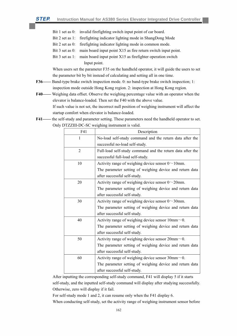
Instruction Manual for AS380 Series Elevator Integrated Drive Controller
162
Bit 1 set as 0: invalid firefighting switch input point of car board.
Bit 2 set as 1: firefighting indicator lighting mode in ShangDong Mode
Bit 2 set as 0: firefighting indicator lighting mode in common mode.
Bit 3 set as 0: main board input point X15 as fire return switch input point.
Bit 3 set as 1: main board input point X15 as firefighter operation switch
Input point.
When users set the parameter F35 on the handheld operator, it will guide the users to set
the parameter bit by bit instead of calculating and setting all in one time.
F36—— Band-type brake switch inspection mode. 0: no band-type brake switch inspection; 1:
inspection mode outside Hong Kong region. 2: inspection at Hong Kong region.
F40—— Weighing data offset. Observe the weighing percentage value with an operator when the
elevator is balance-loaded. Then set the F40 with the above value.
If such value is not set, the incorrect null position of weighing instrument will affect the
startup comfort when elevator is balance-loaded.
F41—— the self-study and parameter setting. These parameters need the handheld operator to set.
Only DTZZIII-DC-SC weighing instrument is valid.
F41 Description
1 No-load self-study command and the return data after the
successful no-load self-study.
2 Full-load self-study command and the return data after the
successful full-load self-study.
10 Activity range of weighing device sensor 0~10mm.
The parameter setting of weighing device and return data
after successful self-study.
20 Activity range of weighing device sensor 0~20mm.
The parameter setting of weighing device and return data
after successful self-study.
30 Activity range of weighing device sensor 0~30mm.
The parameter setting of weighing device and return data
after successful self-study.
40 Activity range of weighing device sensor 10mm~0.
The parameter setting of weighing device and return data
after successful self-study.
50 Activity range of weighing device sensor 20mm~0.
The parameter setting of weighing device and return data
after successful self-study.
60 Activity range of weighing device sensor 30mm~0.
The parameter setting of weighing device and return data
after successful self-study.
After inputting the corresponding self-study command, F41 will display 5 if it starts
self-study, and the inputted self-study command will display after studying successfully.
Otherwise, zero will display if it fail.
For self-study mode 1 and 2, it can resume only when the F41 display 6.
When conducting self-study, set the activity range of weighing instrument sensor before
Instruction Manual for AS380 Series Elevator Integrated Drive Controller
163
starting the mode 1 and mode 2 self studies.
F43—— landing call buzzing/flashing and door-closing standby option when in attendant status.
This parameter is only valid in attendant status.
Among which:
Bit0 set as 1, buzzing inside car when pressing call button
Bit0 set as 0, no buzzing inside car when pressing call button.
Bit1 set as 1, the corresponding inductor button inside car flash to the floor with call
registration.
Bit1 set as 0, no flashing inductor button in car
Bit2 set as 1, door-closing and standby allowed in attendant status.
Bit2 set as 0, door-closing and standby not allowed in attendant status
Bit3 set as 1, schindler attendant mode
Bit3 set as 0, common attendant mode
When users set the parameter F43 on the handheld operator, it will guide the users to set
the parameter bit by bit (function by function) instead of calculating and setting all in
one time.
F44——local address of serial communication, the value of elevator running or single elevator
monitoring is set to 255. If the port 485 community monitoring or port 232 remote
monitoring is applied to banks, every elevator in the bank can be set one of natural
number smaller than 255 for the main board identification by remote PC. Therefore
every elevator in the bank can have independent setting.
F49—— Emergency leveling orientation mode,
0: judge return leveling orientation through pretorque. If the pretorque is less than 0,
return leveling turns upward.
1: judge return leveling orientation through pretorque. If the pretorque is less than 0,
return leveling turns downward.
2: use weighing compensation value to judge the return leveling orientation.
F50—— front door opening allowed. 1. Setting whether the floor 1-16 (floor sequence) allowed
opening or not. The lowest position corresponds to the front door of the lowest floor.
The highest position corresponds to the front door of 16th floor counting from the lowest
floor.
F51—— front door opening allowed. 2. Setting whether the floor 17-32 (floor sequence) allowed
opening or not. The lowest position corresponds to the front door of the 17th floor. The
highest position corresponds to the front door of 32nd floor
F52—— front door opening allowed. 3. Setting whether the floor 33-48 (floor sequence) allowed
opening or not. The lowest position corresponds to the front door of the 33rd floor. The
highest position corresponds to the front door of 48th floor
F191——front door opening allowed. 4. Setting whether the floor 49-64 (floor sequence) allowed
opening or not. The lowest position corresponds to the front door of the 49th floor. The
highest position corresponds to the front door of 64th floor
F53—— rear door opening allowed. 1. Setting whether the floor 1-16 (floor sequence) allowed
opening or not. The lowest position corresponds to the rear door of the lowest floor. The
highest position corresponds to the rear door of 16th floor counting from the lowest
floor.

Instruction Manual for AS380 Series Elevator Integrated Drive Controller
164
F54—— rear door opening allowed. 2. Setting whether the floor 17-32 (floor sequence) allowed
opening or not. The lowest position corresponds to the rear door of the 17th floor. The
highest position corresponds to the rear door of 32nd floor
F55—— rear door opening allowed. 3. Setting whether the floor 33-48 (floor sequence) allowed
opening or not. The lowest position corresponds to the rear door of the 33rd floor. The
highest position corresponds to the rear door of 48th floor
F192——rear door opening allowed. 4. Setting whether the floor 49-64 (floor sequence) allowed
opening or not. The lowest position corresponds to the rear door of the 49th floor. The
highest position corresponds to the rear door of 64th floor
Note: For the above 8 parameters, any of which is set as zero, the front or rear door of the
corresponding floor will not open. If any of the above 8 parameters is set as 1, the front
or rear door of corresponding floor will open. For those in group control or parallel
connection, the floor sequence should be in conformity with that of the whole group.
When conducting the above 8 parameter setting, the parameter should be set layer by
layer (bit by bit) on the operator. Therefore, there is no need to calculate the overall
value.
F56—— Upper leveling precision adjustment
F57—— Down leveling precision adjustment
Upper leveling precision adjustment F56 and down leveling precision adjustment F57 is
only aimed at the condition that the precision deviations of every floor leveling are
same.
The specific adjustment method as following: lower F56 for over-leveling when moving
upward. Increase F56 for under-leveling when moving upward, while lower F57 for
over-leveling when moving downward, increase F57 for under-leveling when moving
downward. The setting scope of F56 and F57 ranges from 0 to 100. The default value is
50, which mean no leveling adjustment.
Note: both parameters F56 and F57 are the compensation adjustment for leveling precision.
Common leveling precision deviation within 15mm can be adjusted with F56 and F57.
If the deviation value is too large, it is recommended to adjust the items such as the
leveling switch installation position, drive parameter, hoistway data-study. If the
leveling precision deviation of each floor is not in conformity with each other, the
installation position of leveling plate of the corresponding floor should be adjusted.
F59—— zero-speed band-type brake delay, switch on band-type brake after F59 time upon the
zero speed reached.
F61—— distance between car and destination leveling position when arrival indicator and arrival
gong activated. The data can be used to adjust the time points given by arrival indicator
and arrival gong. The default is 1200, which mean the two signals will be given by car
at about 1.2m away from the destination floor leveling position.
F62—— time limit for anti-slippage operation, the default is 32. If the elevator fails to receive any
leveling signal within 32 seconds, it will stop service, reporting fault NO 25.( the value
is defined by GB7588-2003 as between 20~45 seconds)
F65—— base electrode lock mode, 0: No base electrode lock mode. 1: immediately turn off the
integrated system output once it detect cutoff of output contactor
F67——Without or with extension board
Instruction Manual for AS380 Series Elevator Integrated Drive Controller
165
F70——Light load uplink gain .Ranges from 0% to 300%. The default value is 100%.
F71——Light load lowlink gain.Ranges from 0% to 300%. The default value is 100%.
F72——Heavy load uplink gain. Ranges from 0% to 300%. The default value is 100%.
F73——Heavy load lowlink gain. Ranges from 0% to 300%. The default value is 100%.
F74——Light load height gain. Ranges from 0 to 1024. The default value is 512.
F75——Heavy load height gain. Ranges from 0 to 1024. The default value is 512.
Note 1:
The parameter F70~F75 is only valid when the F164 set as 0,3,4. Namely: the above
three parameter is only used when the weighing device DTZZ-III-DC-SC or switch of
light-load or full-load is used in elevator for startup preload compensation,
On detailed adjusting method of above three parameters, please take reference
to the section 8, 10 of chapter 8 ( the detailed introduction about adjusting method of
the elevator startup pre-load compensation function)
F115—— time limit for door-opening timeout. If the door-opening limit switch fail to work after
the ending of time set by F115 for door opening. The elevator will stop the door-opening
and turn to close the door. The default value is 15s. range from 3s~30s
F116——time limit for door-closing timeout. If the door-closing limit switch fail to work after the
ending of time set by F116 for door closing. The elevator will stop the door-closing and
turn to open the door. The default value is 15s. range from 3s~30s
F117——forced door closing or opening time duration. Force the door to close or open button
(hold button) the door-opening will maintain for the setting time after pressing the
button
F118—— the disable door-opening time duration, the door-opening time duration for the disable.
F120——Anti-nuisance function and instructions for threshold of judging anti-nuisance.
0: no anti-nuisance function. 1: activation of anti-nuisance function in line with the
action of light curtain: if the elevator park for three floors consecutively without the
activation of light curtain, then the mischief can be identified. All registered instruction
signal will be cleared away.
2-64: activate the anti-nuisance function based on non-empty-load switch and registered
instructions. If the non-empty-load is not activated (the load in car is little, close to
empty-load) but registered instructions are more than the value set by F120, mischief
can be identified by the system. The entire registered instruction signal will be cleared
away.
F121——activate the function of door nudging with buzzer.
0: no activation of the function, 1: activation of the function. When the function of door
nudging with buzzer activated under the circumstance of no presence of attendant, the
elevator door will be closed forcibly once the door keep opening as the result of
repetitive F117 time setting from door-opening button, ROHB function, light curtain
action and etc.
At the same time, the system will close the door forcibly while ignoring the signals from
door-opening button, ROHB function, and light curtain.
F122——Running signal release delay during inspection, the delay time from the disconnection
of band-type contactor output to the turnoff of frequency converter output.
Instruction Manual for AS380 Series Elevator Integrated Drive Controller
166
F123——call controller mode setting, this parameter is used to set the call mode of the call
controller and to define the address of call controller.
0: for the standard 04 program board, only call fro front door. The address 1~48
correspond to the floor 1~48 front door call.
For the customized 04 program board for 64 floors, front door call, rear door call, and
the disabled call all can be provided. The address of 1~64 correspond to the front
door call of the floors 1~64. The address of 65~128 correspond to that of rear door
call, 129~192 correspond to the disabled call.
1: only for standard 04 program board, front door call and rear door call
are provided. The address of 1~48 correspond to the front door call of the floor 1~
48.
2: only for standard 04 program board, front door call and the disabled call are provided.
The address of 1~48 corresponded to the front door call of the floor 1~48, 49~96
corresponded to the disabled door call of floor 1~48
3: only for standard 04 program board, the highest floor is 32nd. Front door call, rear
door call, the disabled call are provided. The address of 1~32 corresponded to the
front door call of the floor 1~32. 33~64 corresponded to the rear door call of the
floor 1~32, 65~96 corresponded to the disabled call of the floor 1~32.
F124——the function definition of X16 input point of main board
0: Input point of emergency leveling function under the circumstance of blackout.
1: action input point of earthquake device
2: input point for emergency power supply condition of the building emergency
power supply operation function.
F128—— control mode for front/ rear door. 0: the separate control of front door
and rear door. 1: integrated control of front door and rear door.
F129—— activate the pre-opening of door and re-leveling of door opening.
The range set from 0 to 3. 0: all deactivated. 1: only activate the pre-opening of door.
2: only activate the function of re-leveling of door-opening. 3 activated both two
functions mentioned above.
F130—— holding door-opening/closing torque. 0: no torque holding. 1: door-opening torque
holding, 2: door-closing torque holding, 3: door-opening/closing torque. 4: only
the door-closing torque holding during operation.
F131~F133 ——F131-F133 Time section floor blockade floor set related parameter. F131 is the floor setting, F132 is the beginning time setting, F133 is the closure time setting. Related parameter F161 is the turn-on time section floor function parameter.
The following is establishes the demonstration:
When F131 = 1, establishes F132 = 1000, F133 is 1200, then 1 building's blocking time is 10:00-12:00
When F131 = 1, establishes F132 = 2300, F133 is 800, then 1 building blocking time for evening 23:00 to second day of early morning 8:00
Adjusts F131 value and corresponding F132 and F133 may establish 64 floor time section blocking time, does not block the floor does not establish F132 and F133 then
F132 and the F133 time establishment's range of validity is 0-2359 expressing 0:00:23:59.
F137~F139,F199—non service floor setting of switch control. F137 set the value from the
Instruction Manual for AS380 Series Elevator Integrated Drive Controller
167
bottom floor to the 16th floor. The bottom bit corresponds to the bottom floor. The
highest bit corresponds to 16th floor. F138 set the value from 17th floor to 32nd
floor. The lowest bit corresponded to 17th floor. The highest floor corresponded to
32nd floor. F139 set the value from floor 33rd to floor 48th. The lowest bit
corresponded to 33rd floor. The highest floor corresponded to 48th floor. F199 set
the value from 49th floor to 64th floor. The lowest floor corresponded to floor 49th.
The highest floor corresponded to 64th floor. When the bit is set as 1, the
corresponding floor will be non-service floor during the switch validity. The
instructions and call signal from the floor can not be registered. The parameters
are under the control of a switch.
The parameters will be invalid when the switch deactivated. If setting the
parameters in group control or parallel connection, the floor sequence must be in
conformity with that of the whole group.
detailed setting method. Please take reference to the setting method of
F50-F52,F191.
F141—— delay release time of main contactor. The time delay range from the elimination of
running signal to main contactor release while the elevator stopped. The default is
0.5s.
F145—— busbar voltage gain. If it is found during the inspection that there is error between the
busbar voltage in display and that in actual inspection, set the parameter F145 to make
the above two data consistent. The default is 100%, which mean no adjustment.
F146—— position deviation distance. Do inspection on the deviation of leveling position when
stop the elevator. The parameter represents the allowed deviation distance.
F147—— contact inspection protection mode. 0: self-protection against fault after detecting the
contacts adhesion failure. Power cutoff or inspection reset is required. 1: stop the
elevator when detecting contact adhesion and keep running after the troubleshooting.
F152—— the delay time of auto shutdown of in-car lighting and fan. The system will
automatically shut down the in-car lighting and fan when idle time of elevator in
automatic mode reach the value set by the parameter. The default value is 3 minutes.
F153—— high-voltage input detection with or without hall door lock
1: high-voltage input detection with hall door lock.
0: high-voltage input detection without hall door lock.
The default value is 1.
F156—— detection on existence of door lock relay. 1: yes, 0: no
F160—— activation/deactivation of manually clearing away error instruction .
1: activation, 2: deactivation. When such function is activated, the wrong instruction
signal can be cleared away by pressing the button twice once the wrong instruction
signal is registered.
F161—— activation/deactivation of time slot floor blockade
1: activation, 0: deactivation.
F163—— the elevator continue to run or stop after homing while the signal or parallel backup
power supply is running. 0: the elevator stops after homing while backup power
supply is running.1: the elevator continues to run after homing while the backup
power supply is running.
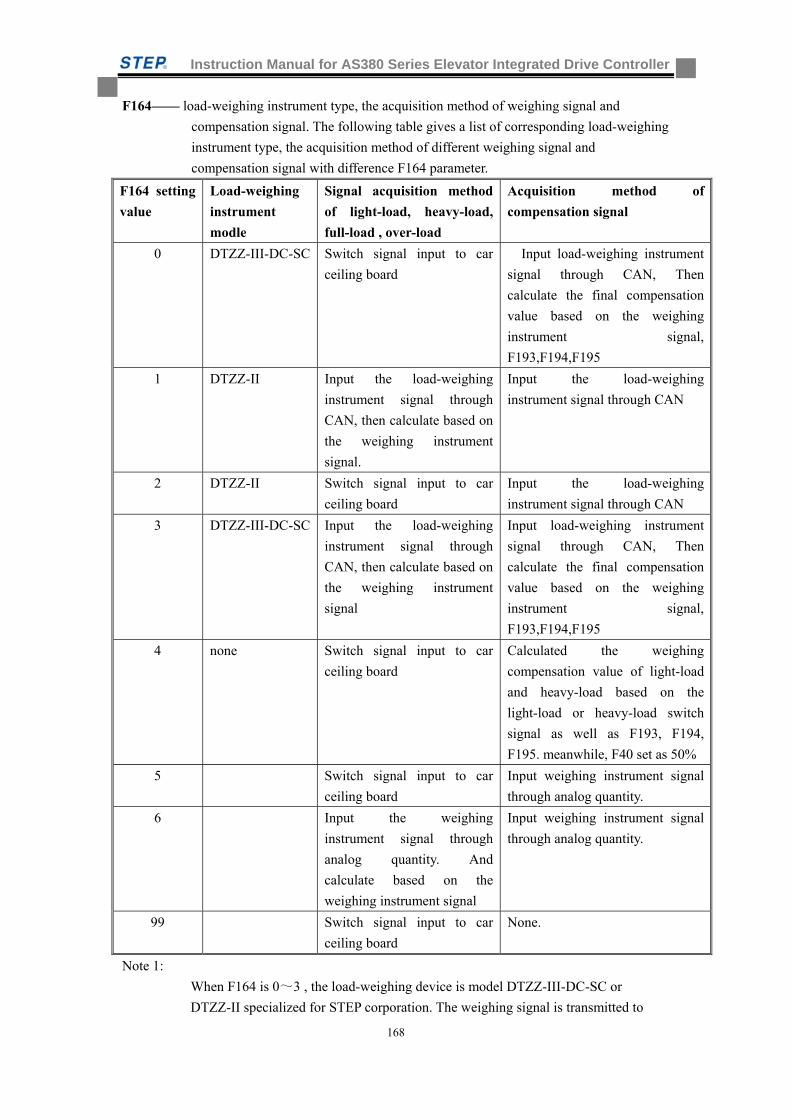
Instruction Manual for AS380 Series Elevator Integrated Drive Controller
168
F164—— load-weighing instrument type, the acquisition method of weighing signal and
compensation signal. The following table gives a list of corresponding load-weighing
instrument type, the acquisition method of different weighing signal and
compensation signal with difference F164 parameter.
F164 setting
value
Load-weighing
instrument
modle
Signal acquisition method
of light-load, heavy-load,
full-load , over-load
Acquisition method of
compensation signal
0 DTZZ-III-DC-SC Switch signal input to car
ceiling board
Input load-weighing instrument
signal through CAN, Then
calculate the final compensation
value based on the weighing
instrument signal,
F193,F194,F195
1 DTZZ-II Input the load-weighing
instrument signal through
CAN, then calculate based on
the weighing instrument
signal.
Input the load-weighing
instrument signal through CAN
2 DTZZ-II Switch signal input to car
ceiling board
Input the load-weighing
instrument signal through CAN
3 DTZZ-III-DC-SC Input the load-weighing
instrument signal through
CAN, then calculate based on
the weighing instrument
signal
Input load-weighing instrument
signal through CAN, Then
calculate the final compensation
value based on the weighing
instrument signal,
F193,F194,F195
4 none Switch signal input to car
ceiling board
Calculated the weighing
compensation value of light-load
and heavy-load based on the
light-load or heavy-load switch
signal as well as F193, F194,
F195. meanwhile, F40 set as 50%
5 Switch signal input to car
ceiling board
Input weighing instrument signal
through analog quantity.
6 Input the weighing
instrument signal through
analog quantity. And
calculate based on the
weighing instrument signal
Input weighing instrument signal
through analog quantity.
99 Switch signal input to car
ceiling board
None.
Note 1:
When F164 is 0~3 , the load-weighing device is model DTZZ-III-DC-SC or
DTZZ-II specialized for STEP corporation. The weighing signal is transmitted to
Instruction Manual for AS380 Series Elevator Integrated Drive Controller
169
main board through CAN. When F164 is 4, the elevator is without electronic
weighing device but mechanic weighing switch. When F164 is 5 and 6, the elevator
weighing device is other type device. The weighing signal is transmitted into analog
quantity input port through analog quantity of DC 0~10V.
Note 2:
When F164 is 0,2,4,,5, the over-load, full-load, light-load switch signal
is acquired through inputted switching value signal. When F164 is 1,3,6,
the over-load, full-load, light-load switch signal is calculated based on inputted
weighing signals.
Note 3:
When F164 is 0 and 3, the pre-load compensation value at startup is calculated based
on the data of weighing signal plus that of linear correction results of
F193,F194,F195 .When F164 is 4, make sure the car loading condition based on
light-load or heavy load switch signal before doing else. Then, calculate the pre-load
weighing compensation value of light-load and heavy-load based on the parameters
F193,F194,F195. When F164 is 1,2,5 and 6, use the weighing data obtained from
weighing device as the pre-loading weighing compensation value.
F165—— special control parameters for door operation. Bit 0: door operation allowed or not in
inspection. Bit1: door-opening allowed or not during the period of adjustment and
setting. Bit2: elevator standby with/without door-opening. Bit 3: door operation with
or without onboard LED operator.
F168—— elevator serial number with IC card service.
F169—— hall up/down IC card-based call. 0: down call, 1: up call.
F170—— when the in-car IC card instruction registration is on, the corresponding floor 1~16
require IC card-swiping selection. The corresponding bit 1 represents the need for IC
card-swiping registration. 0 represent no need for IC car-swiping.
F171—— when the in-car IC car instruction registration is on, the corresponding floor 17~32
require IC card-swiping selection.
F172—— when the in-car IC car instruction registration is on, the corresponding floor 33~48
require IC card-swiping selection.
F175—— creeping speed at startup. For the comfort adjustment at startup
When starting resistance of tractor is too much, the tractor will be adjusted
appropriately to the startup creeping speed. When creep speed at startup is set as 0. it
is in no use. This value should be used together with that of startup creeping duration
F186.
F180—— speed gain. Gain for the speed given peak. The range is from 0.0% to 110.0%
The default value is 1000. (Reading as 100.0%)
F181—— mutual parallel mode ( F23=3) of elevator number setting. The range is 0~1, the
main elevator setting is 0. The auxiliary elevator is 1.
F182—— the installation series of deceleration switch at hoistway.(Equal to the half
deceleration switch number) Setting 0 represent the deceleration switch series based
on rated speed (see table 4.1)
F183—— setting the running speed during the hositway self-study.
F186—— creeping duration at startup, for adjusting the startup comfort. It can be used together
Instruction Manual for AS380 Series Elevator Integrated Drive Controller
170
with startup creeping speed F175.
F187—— Monitoring items
The display position of running times in the main interface of operator can be set by
F187 to show various kinds of monitoring items. Take the 00000088 in the following
figure as example.
F187 set as 0: to display the running times of elevator
F187 set as 1: to display the interference evaluation. The meaning of the counting is to
record the interference situation of last time running.
The number can be updated only when the elevator stop. If there is no-interference,
the number should be 0. When the counting reaches 1000 great interference from
encoder should be identified. There is need to test the interference situation of
encoder.
F187 set as 2: to display the fault counter of CAN1(the CAN communication between
hoistway and car). The meaning of this counter: if the CAN communication is ok,
the value should be 0.If the counting reach 96, big problem for communication
should be identified. It is necessary to check the communication line.
F187 set as 3: to display the fault counter of CAN2 (the CAN communication in group
control or parallel connection). The meaning of this counter: if the CAN
communication is ok, the value should be 0.If the counting reach 96, big problem
for communication should be identified. It is necessary to check the communication
line.
F187 set as 4: to display the running speed of motor. The unit is rpm
F187 set as 5: to display the voltage of busbar. The unit is V
F187 set as 6: to display the output current, the unit is 0.01A
F187 set as 7: to display the output torque, the unit is ‰ ( rated load)
F187 set as 11: to display the pre-torque, the unit is ‰ ( rated load)
F187 set as 14: to display the weighing value.
F193—— No-load compensation value on the bottom floor when elevator start up with the
function of pre-load compensation. The value ranges from 0 to 1000.
1000 is 100.0%, which mean the given compensation is 100% rated torque.
F194—— full-load compensation value on the bottom floor when elevator start up with the
function of pre-load compensation. The value ranges from 0 to 1000.1000 is 100.0%,
which mean the given compensation is 100% rated torque.
F195—— No-load compensation value on the top floor when elevator start up with the function
of pre-load compensation. The value ranges from 0 to 1000.
1000 is 100.0%, which mean the given compensation is 100% rated torque.
Note 1:
The parameter F193~F195 is only valid when the F164 set as 0,3,4. Namely: the
above three parameter is only used when the weighing device DTZZ-III-DC-SC or
switch of light-load or full-load is used in elevator for startup preload compensation,
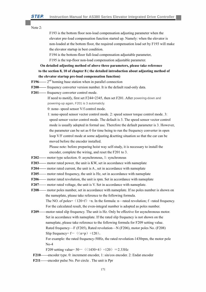
Instruction Manual for AS380 Series Elevator Integrated Drive Controller
171
Note 2:
F193 is the bottom floor non-load compensation adjusting parameter when the
elevator pre-load compensation function started up. Namely: when the elevator is
non-loaded at the bottom floor, the required compensation load set by F193 will make
the elevator startup in best condition.
F194 is the bottom-floor full-load compensation adjustable parameter,
F195 is the top-floor non-load compensation adjustable parameter.
On detailed adjusting method of above three parameters, please take reference
to the section 8, 10 of chapter 8 ( the detailed introduction about adjusting method of
the elevator startup pre-load compensation function)
F196—— 2nd homing base station when in parallel connection
F200—— frequency converter version number. It is the default read-only data.
F201—— frequency converter control mode.
If need to motify, first set F244=2345, then set F201. After powering-down and
powering-up again, F201 is 3 automaticly.
0: none- speed sensor V/f control mode.
1: none-speed sensor vector control mode. 2: speed sensor torque control mode. 3:
speed sensor vector control mode. The default is 3. The speed sensor vector control
mode is usually adopted in formal use. Therefore the default parameter is 3. However,
the parameter can be set as 0 for time being to run the frequency converter in open
loop V/F control mode at some adjusting &setting situation so that the car can be
moved before the encoder installed.
Please note: before preparing hoist way self-study, it is necessary to install the
encoder, complete the wiring, and reset the F201 to 3.
F202—— motor type selection. 0: asynchronous, 1: synchronous
F203—— motor rated power, the unit is KW, set in accordance with nameplate
F204—— motor rated current, the unit is A , set in accordance with nameplate
F205—— motor rated frequency, the unit is Hz, set in accordance with nameplate
F206—— motor rated revolution, the unit is rpm. Set in accordance with nameplate
F207—— motor rated voltage, the unit is V. Set in accordance with nameplate.
F208—— motor poles number, set in accordance with nameplate. If no poles number is shown on
the nameplate, please take reference to the following formula.
The NO. of poles=(120×f)÷n. In the formula: n—rated revolution; f –rated frequency.
For the calculated result, the even-integral number is adopted as poles number.
F209——motor rated slip frequency. The unit is Hz. Only be effective for asynchronous motor.
Set in accordance with nameplate. If the rated slip frequency is not shown on the
nameplate, please take reference to the following formula for F209 setting value.
Rated frequency—F (F205), Rated revolution—N (F206), motor poles No. (F208)
Slip frequency= f-((n×p)÷120)。
For example: the rated frequency-50Hz, the rated revolution-1430rpm, the motor pole
No-4
F209 setting value= 50-((1430×4)÷120)=2.33Hz
F210——encoder type. 0: increment encoder, 1: sin/cos encoder. 2: Endat encoder
F211——encoder pulse No. Per circle . The unit is Ppr
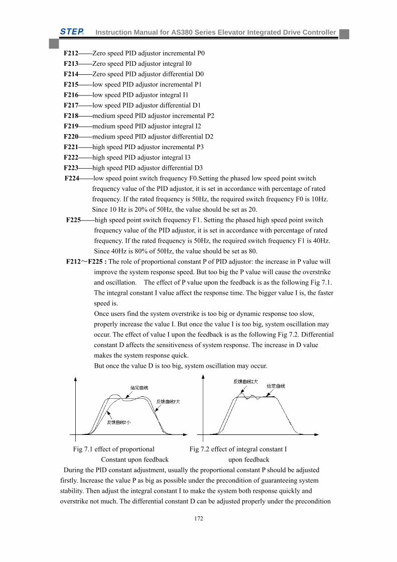
Instruction Manual for AS380 Series Elevator Integrated Drive Controller
172
F212——Zero speed PID adjustor incremental P0
F213——Zero speed PID adjustor integral I0
F214——Zero speed PID adjustor differential D0
F215——low speed PID adjustor incremental P1
F216——low speed PID adjustor integral I1
F217——low speed PID adjustor differential D1
F218——medium speed PID adjustor incremental P2
F219——medium speed PID adjustor integral I2
F220——medium speed PID adjustor differential D2
F221——high speed PID adjustor incremental P3
F222——high speed PID adjustor integral I3
F223——high speed PID adjustor differential D3
F224——low speed point switch frequency F0.Setting the phased low speed point switch
frequency value of the PID adjustor, it is set in accordance with percentage of rated
frequency. If the rated frequency is 50Hz, the required switch frequency F0 is 10Hz.
Since 10 Hz is 20% of 50Hz, the value should be set as 20.
F225——high speed point switch frequency F1. Setting the phased high speed point switch
frequency value of the PID adjustor, it is set in accordance with percentage of rated
frequency. If the rated frequency is 50Hz, the required switch frequency F1 is 40Hz.
Since 40Hz is 80% of 50Hz, the value should be set as 80.
F212~F225 : The role of proportional constant P of PID adjustor: the increase in P value will
improve the system response speed. But too big the P value will cause the overstrike
and oscillation. The effect of P value upon the feedback is as the following Fig 7.1.
The integral constant I value affect the response time. The bigger value I is, the faster
speed is.
Once users find the system overstrike is too big or dynamic response too slow,
properly increase the value I. But once the value I is too big, system oscillation may
occur. The effect of value I upon the feedback is as the following Fig 7.2. Differential
constant D affects the sensitiveness of system response. The increase in D value
makes the system response quick.
But once the value D is too big, system oscillation may occur.
Fig 7.1 effect of proportional Fig 7.2 effect of integral constant I
Constant upon feedback upon feedback
During the PID constant adjustment, usually the proportional constant P should be adjusted
firstly. Increase the value P as big as possible under the precondition of guaranteeing system
stability. Then adjust the integral constant I to make the system both response quickly and
overstrike not much. The differential constant D can be adjusted properly under the precondition
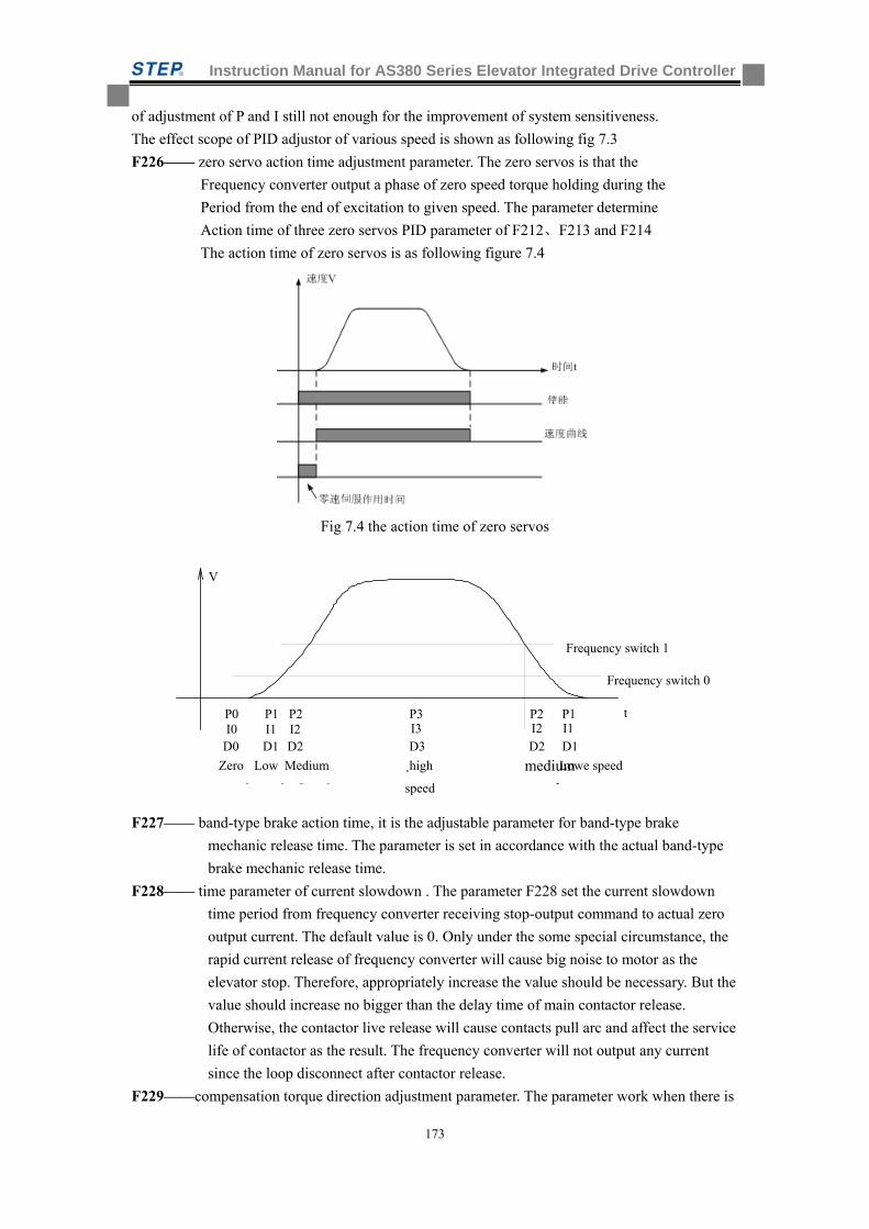
Instruction Manual for AS380 Series Elevator Integrated Drive Controller
173
of adjustment of P and I still not enough for the improvement of system sensitiveness.
The effect scope of PID adjustor of various speed is shown as following fig 7.3
F226—— zero servo action time adjustment parameter. The zero servos is that the
Frequency converter output a phase of zero speed torque holding during the
Period from the end of excitation to given speed. The parameter determine
Action time of three zero servos PID parameter of F212、F213 and F214
The action time of zero servos is as following figure 7.4
Fig 7.4 the action time of zero servos
F227—— band-type brake action time, it is the adjustable parameter for band-type brake
mechanic release time. The parameter is set in accordance with the actual band-type
brake mechanic release time.
F228—— time parameter of current slowdown . The parameter F228 set the current slowdown
time period from frequency converter receiving stop-output command to actual zero
output current. The default value is 0. Only under the some special circumstance, the
rapid current release of frequency converter will cause big noise to motor as the
elevator stop. Therefore, appropriately increase the value should be necessary. But the
value should increase no bigger than the delay time of main contactor release.
Otherwise, the contactor live release will cause contacts pull arc and affect the service
life of contactor as the result. The frequency converter will not output any current
since the loop disconnect after contactor release.
F229——compensation torque direction adjustment parameter. The parameter work when there is
V
P0 I0
P1 P2 P3 P1P2I1 I2 I3 I1I2
D0 D1 D1D2 D2D3
Frequency switch 1
Frequency switch 0
t
Zero
d
Low
d
Lowe speedMedium
S d
medium
d
¸high
speed
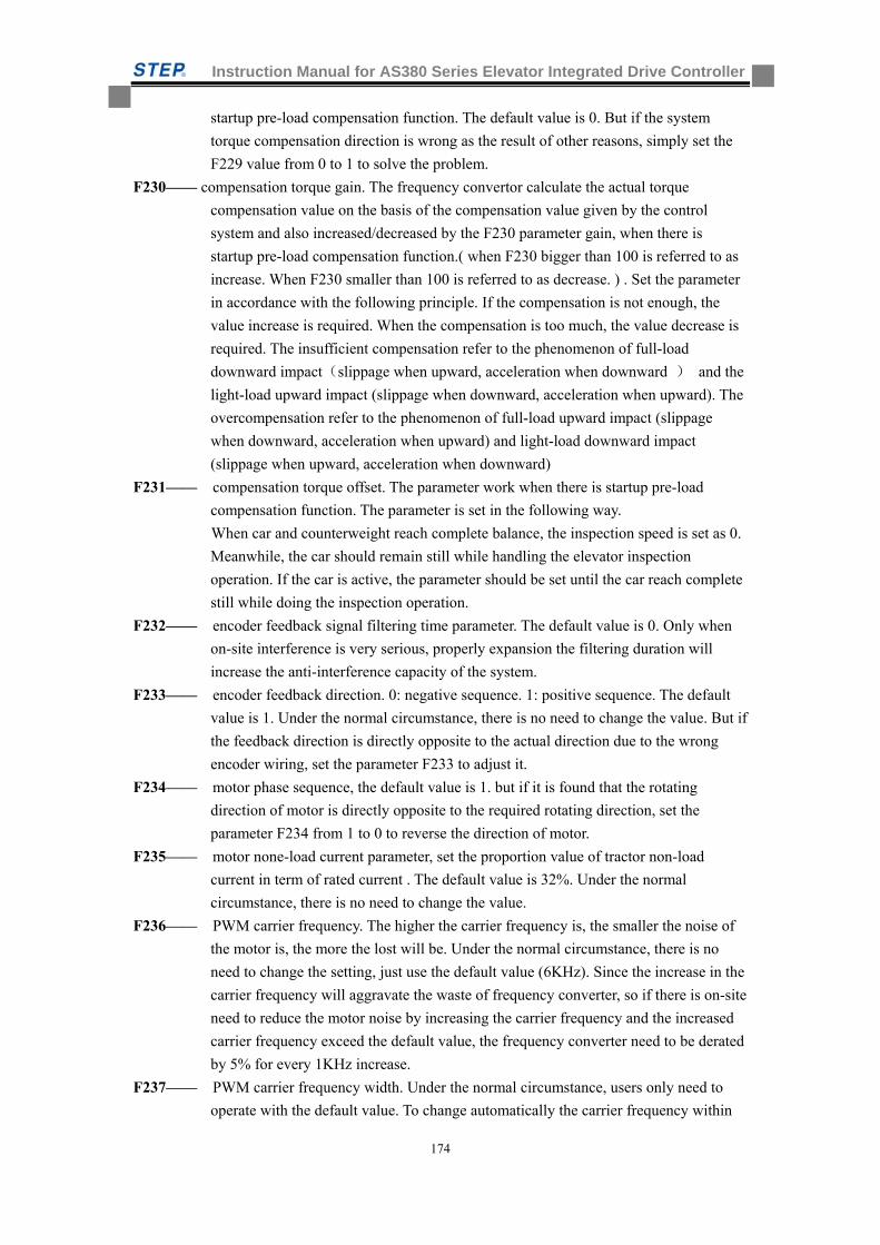
Instruction Manual for AS380 Series Elevator Integrated Drive Controller
174
startup pre-load compensation function. The default value is 0. But if the system
torque compensation direction is wrong as the result of other reasons, simply set the
F229 value from 0 to 1 to solve the problem.
F230—— compensation torque gain. The frequency convertor calculate the actual torque
compensation value on the basis of the compensation value given by the control
system and also increased/decreased by the F230 parameter gain, when there is
startup pre-load compensation function.( when F230 bigger than 100 is referred to as
increase. When F230 smaller than 100 is referred to as decrease. ) . Set the parameter
in accordance with the following principle. If the compensation is not enough, the
value increase is required. When the compensation is too much, the value decrease is
required. The insufficient compensation refer to the phenomenon of full-load
downward impact(slippage when upward, acceleration when downward ) and the
light-load upward impact (slippage when downward, acceleration when upward). The
overcompensation refer to the phenomenon of full-load upward impact (slippage
when downward, acceleration when upward) and light-load downward impact
(slippage when upward, acceleration when downward)
F231—— compensation torque offset. The parameter work when there is startup pre-load
compensation function. The parameter is set in the following way.
When car and counterweight reach complete balance, the inspection speed is set as 0.
Meanwhile, the car should remain still while handling the elevator inspection
operation. If the car is active, the parameter should be set until the car reach complete
still while doing the inspection operation.
F232—— encoder feedback signal filtering time parameter. The default value is 0. Only when
on-site interference is very serious, properly expansion the filtering duration will
increase the anti-interference capacity of the system.
F233—— encoder feedback direction. 0: negative sequence. 1: positive sequence. The default
value is 1. Under the normal circumstance, there is no need to change the value. But if
the feedback direction is directly opposite to the actual direction due to the wrong
encoder wiring, set the parameter F233 to adjust it.
F234—— motor phase sequence, the default value is 1. but if it is found that the rotating
direction of motor is directly opposite to the required rotating direction, set the
parameter F234 from 1 to 0 to reverse the direction of motor.
F235—— motor none-load current parameter, set the proportion value of tractor non-load
current in term of rated current . The default value is 32%. Under the normal
circumstance, there is no need to change the value.
F236—— PWM carrier frequency. The higher the carrier frequency is, the smaller the noise of
the motor is, the more the lost will be. Under the normal circumstance, there is no
need to change the setting, just use the default value (6KHz). Since the increase in the
carrier frequency will aggravate the waste of frequency converter, so if there is on-site
need to reduce the motor noise by increasing the carrier frequency and the increased
carrier frequency exceed the default value, the frequency converter need to be derated
by 5% for every 1KHz increase.
F237—— PWM carrier frequency width. Under the normal circumstance, users only need to
operate with the default value. To change automatically the carrier frequency within
Instruction Manual for AS380 Series Elevator Integrated Drive Controller
175
the width range so as to reduce the motor noise in some situation. For example, the
setting value of F236 is 6KHz, the setting value of F237 is 0.4KHz. the actual carrier
frequency of frequency converter change automatically within the scope of 5.8~
6.2KHz
F238—— adjustor mode. Generally the default value is 1. The standard adjustor mode
F239—— output torque limit. It set the limit value of output torque. It is percentage data of
rated torque. the default value is 175(175%)
F240—— rated voltage of frequency converter. Setting the output voltage of frequency
converter
F241—— rated power of frequency converter. It is default value. for the reference only,
Modification not allowed.
F242—— phase angle of encoder. It is the encoder phase angle data automatically acquired by
the system. For the reference only
F243—— zero position correction of encoder. 0: regular mode. 2: encoder zero position
correction. When the operation inspections are ok, synchronize the elevator to do the
encoder zero-position correction to realize the better control precision. The specific
method as follow: at first, set the inspection speed to 4 rpm. Then set the F243 to 2.
Press up-down button to run the elevator at low speed for 30 seconds. And then the
integrated control will stop. The F243 turn to 0 and the encoder zero-position
correction completed.
F245—— F246~F255 parameter function selection. Change the parameter will make the
definition of F246~F255 different. The range is 0~6. The default value is 0.
When F245=0
F246—— Overheating protection time for radiator. The integrated unit starts protection when the
radiator overheating time duration exceed the setting time.
F247—— Over-speed protection coefficient. The integrated unit launches the protection when
the following two conditions are met: 1) the motor rotating speed monitored by the
integrated unit exceed the protection coefficient set by the parameter.2)the motor
over-speed time duration exceed the over-speed protection time set by the parameter.
F248—— Over-speed protection time. Setting the protection time duration for the motor
over-speed
F249—— the confirming number of times of open phase input. At certain instant the open phase
input exceeds the number of times set by the parameter. Then the protection is
launched.
F250—— the confirming number of times of brake resistor short-circuit. At certain instant the
numbers of times of brake resistor short-circuit exceed that set by the parameter. The
protection is launched.
F251—— the confirming numbers of time of Sin/Cos encoder disconnection. At certain instant
the confirming numbers of time of Sin/Cos encoder disconnection exceed that set by
the parameter. The protection is launched.
F252—— confirming time of output open phase. The output open phase exceeds the time
duration set by the parameter. Then the protection launched.
F253—— Confirmation of voltage for charging relay failure. Protection after the three-phase
in-operation input voltage fall below the value set by the parameter and fault No 144
Instruction Manual for AS380 Series Elevator Integrated Drive Controller
176
reported. The charging relay may be damaged or the grid voltage is suddenly
decreased.
The Fault No 114 reported due to insufficient capacity of temporary power supply
adopted at the beginning of on-sit adjustment and setting. Meanwhile, it is impossible
to improve the capacity of power supply at the working place. Under such
circumstance, users can confirm that the charging relay of frequency converter is ok if
they can hear the sound of relay close and open inside of frequency converter when
the frequency convert is power-on or power-off. Then users can realize this kind of
the elevator running with the temporary power by changing the parameter of the
frequency converter. The detailed method is as follow:
Change the parameter F253 from default value 45 to 90. In this way the elevator can
run with low-capacity power supply. When the on-site installation is completed,
change the parameter value back to the default value of 45 when the normal power
supply is recovered.
F254—— encoder CD phase fault confirmation threshold. The default value is 300. When the
difference value between the encoder absolute position and calculation position
exceed the setting value, the No.28 fault reported.
When selecting not to do self-study with power on (F245=6, F246=0). The integrated
unite will automatically activate the encoder C/D phase inspection. If it is found that
C/D phase position is not correct, the setting threshold of F254 exceed, the integrated
unit will report No 98 default.
Please note the if value F245 (F245=6) change from 1 to 0 on the site, the No 98 fault
will reported, because C/D phase position is not inspected when F245=1(F245=6),and
disconnection or wrong connection does not matter. The fault inspection is only for
sincos encoder and Endata encoder.
F255—— ABZ encoder disconnection protection threshold. The default value is 20%. When the
synchronous motor adopted the ABZ encoder, the encoder disconnection is identified
once the feedback speed deviation exceeds the protection threshold. The No 12 fault
is reported with the frequency converter.
When F245=1
F246---- Times og Instantaneous overcurrent of IGBT
F247---- 0:two ways of I2t protection,1:only the first way of I2t protection,2: only the second way
of I2t protection
When F245=2
F247—— PWM adjustment mode. 0: 5 stages, 1: 7 stages, 2: <40%rpm 7stages, >40% 5 stages.
The integrated units at low-speed cause too much interference to outside. For example,
change to 0 (5 stages) for the improvement of CAN communication signal and for
heating reduction of frequency converter. But in this way will possible cause the loud
noise of frequency converter at low speed.
F250—— three phase current balance coefficient. This parameter is read-only parameter; it will
change automatically after doing the three-phase electricity balance coefficient
calibration. If it is synchronous motor, activation of synchronous motor self-study
command will close the output contactor and conduct the three-phase current
calibration. This function will reduce the motor vibration and improve the comfort.
Instruction Manual for AS380 Series Elevator Integrated Drive Controller
177
the detailed method of three-phase current sensor calibration is as following: first of
all, find the asynchronous motor self-study mode in the adjustment menu of the
portable operator, press the confirmation key and the integrated unit will output the
KMY closing command to make the contactor closed. Then the operator will display
“studying” for 30 seconds while conducting three-phase current sensor
self-calibration. The operator will display “study complete” when study successfully.
At this time set the F245 to 2, and obverse the F250 to be the value between 800 and
1200 (1000 not allowed). The default value of F250 is 1000. The value can not be
1000 after self-study. Otherwise, redo the self-study until the correct value is
obtained.
F252—— 0:allow Positive /negtive rotation 1:only allow positive rotation
F253—— The zero-speed time of positive/negative rotation change
F254—— accelerated over-current threshold of frequency converter. Acceleration will stop if
current exceed the setting value during the process of the acceleration. And current
speed is maintained. Acceleration will resume after the current drop.
F255—— decelerated over-voltage threshold of frequency converter. Deceleration will stop if
busbar voltage exceeds the setting value during the process of the deceleration. The
current speed is maintained. Deceleration will resume after the voltage drop.
When F245=3
F246—— the integral P of current loop PID adjuster, no adjustment needed.
F247—— the integral I of current loop PID adjuster, no adjustment needed.
F248—— the integral D of current loop PID adjuster, no adjustment needed.
F254—— Torque direction 0:positive 1:negative
When F245=4
F246—— Software version code. Read-only parameter
F247—— ID NO 0. Read-only parameter
F248—— ID NO 1. Read-only parameter
F249—— ID NO 2. Read-only parameter
F250—— ID NO 3. Read-only parameter
F251—— ID NO 4. Read-only parameter
F252—— ID NO 5. Read-only parameter
F253—— rated current of the integrated unit, read-only parameter.
F254—— rated current of the integrated unit current sensor, Read-only parameter.
F255—— Motor power coefficient Set the max power output, generally do not need to change
When F245=5
F246—— Stator resistor. The stator resistor of asynchronous motor
F247—— rotor resistance. Rotor resistance of asynchronous motor
F248—— Stator inductor. The stator inductor of asynchronous motor
F249—— rotor inductor. The rotor inductor of asynchronous motor
F250—— Mutual inductor. The mutual inductor of asynchronous motor
F251—— Motor low-speed over current threshold. When the motor speed is lower than the 20%
rated speed, motor stop and motor low-speed over current reported when the current
exceed the setting value and the over current time duration exceed that set by the
F252.
Instruction Manual for AS380 Series Elevator Integrated Drive Controller
178
F252—— Low-speed over current time. The duration of motor low-speed over current
F253—— Motor high-speed over current threshold. When the motor speed is higher than the
20% rated speed, motor stop and motor high-speed over current reported when the
current exceed the setting value and the over current time duration exceed that set by
the F254.
F254—— high-speed over current time. The time duration of motor high-speed over current
F255—— Frequency dividing coefficient of encoder. This parameter selects the frequency
dividing output coefficient of PG card, the default value is 0. It requires the PG card
with frequency dividing output function.
0: ( no frequency dividing), 1:( 2 frequency dividing), 2: (4 frequency dividing),3:(8
frequency dividing),4: (16 frequency dividing),5 (32 frequency dividing),6:(64
frequency dividing), 7: (128 frequency dividing)
When F245=6
F246—— self study selection or not when power on . The default is 1: self-study every time
when power on. If it changes to 0, never conduct another self-study when power on
once the self-study has been done. (Only for sincos encoder and Endata encoder) .user
can manually change the phase angel F242 data. If F242 value is 0, the integrated unit
will conduct self-study automatically. Please note: once F246 (F245=6) set as 0 and
main unit or rotary encoder has been replaced, F242 should be set as 0 to do a
self-study. Otherwise, the wrong phase angel will cause the vibration of motor.
F247—— current gain when conducting self-study. The default value is 150, which mean the
default phase self-study is done with 1.5 times rated current
When using special main unit (such as BOMA motor) on site, phase self-study is
required for several times. After the self-study is completed, there is the need to run
main unit once. The phase angle position obtained can be seen at F242. Change F242
to 0, the main unit can do the self-study even without power disconnection.
Comparing the F242 values obtained from self-study each time, increase the F247
( when F245=6) to redo the self-study until the deviation of self-study every time is
less than 10 if the variation range is more than +10~-10.
F247 (when F245=6) value should not be too high, otherwise the main unit running at
the first time after the self-study will cause noise. So it is ok to set the value below
300.
For BOMA main unit on site, the value should be set as 250 to do the self-study. Its
phase angle deviation is within 8.
F248—— command option. It is used to choose the running command.
F249—— Zero servo process current loop gain. Current loop gain in the zero servo process
F252—— set 6616,open anti-slipping function.
Cattier frequency(F236=4.000kHz)
Cancel 1 fault(F245=2,F246=64), The original is 0
Cancel 21 fault(F245=1,F246=40000), The original is 2
Cancel 27 fault(F245=1,F247=1), The original is 0
Every time it run, F252 minus 1,F252 greater than 6616 or less than or equal to 6606,then F252
is 0 automaticly 自;after power off and power on,F252 is 0Chapter 8 Elevator adjustment and
setting instructions
Instruction Manual for AS380 Series Elevator Integrated Drive Controller
179
This chapter provides the guide for operation of elevator. Following the operation procedures described in this chapter to complete the design, installation, wiring, parameter setting and commissioning of elevator quickly.
Important Notice:
Any users of our products are required to carefully read and understand this manual and the related equipment manuals of the system prior to starting system commissioning or putting it into operation in order to avoid accidentals losses.
Be sure to read and understand the instructions for System Parameter Setting in this manual prior to starting system commissioning or putting it into operation in order to avoid accident losses.
Site commissioning can not be started until all mechanical equipment, especially shaft equipments and devices are installed reliably (The equipment required in the machine room depends on the preparation of machine room).
Any equipment and devices required to be installed and commissioned before system commissioning shall be surely completed in a reliable manner.
Before commissioners starting its works, all the works must be confirmed by the related installation persons and commissioning director of mechanical system and other system or by the other persons designated to taking the related responsibilities.
Prior to system commissioning, the commissioner shall carefully check all the equipment and other devices related to the commissioning of electric system are all completely installed and commissioned appropriately.
Prior to system commissioning, the commissioner must carefully check there is not any existences of unsafe factors to human body and property (including potential and possible unsafe factors).
The commissioner must be of trained and qualified to execute commissioning of elevator control system.
In case that this manual can not satisfy your requirements, please contact us timely to get supporting in time.
Commissioner shall, before starting its work, check all the site conditions are ready to carry out system commissioning.
don’t remove the shell when power is on
Or it may cause risk of electric shock.
Do not reset alarm signals until operating signals are surely cut off
Or it may cause risk of injury.
Danger
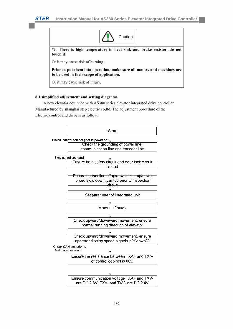
Instruction Manual for AS380 Series Elevator Integrated Drive Controller
180
There is high temperature in heat sink and brake resistor ,do not touch it
Or it may cause risk of burning.
Prior to put them into operation, make sure all motors and machines are to be used in their scope of application.
Or it may cause risk of injury.
8.1 simplified adjustment and setting diagrams
A new elevator equipped with AS380 series elevator integrated drive controller
Manufactured by shanghai step electric co,ltd. The adjustment procedure of the
Electric control and drive is as follow:
Caution
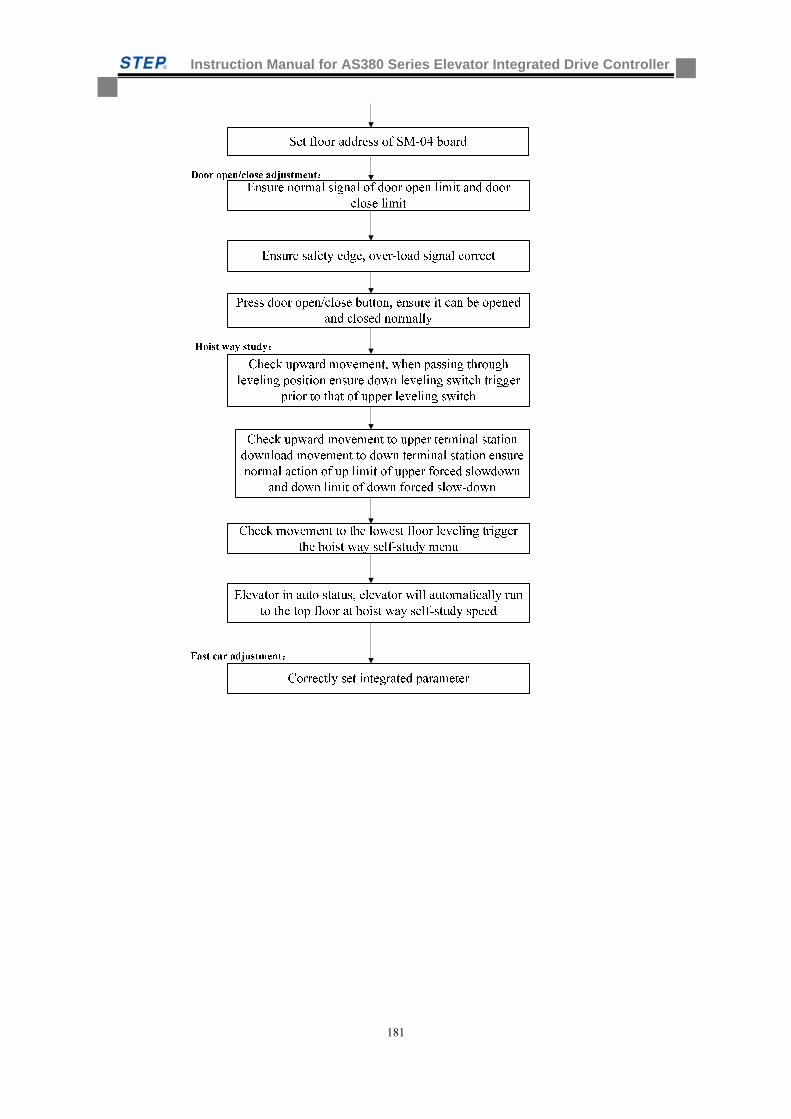
Instruction Manual for AS380 Series Elevator Integrated Drive Controller
181
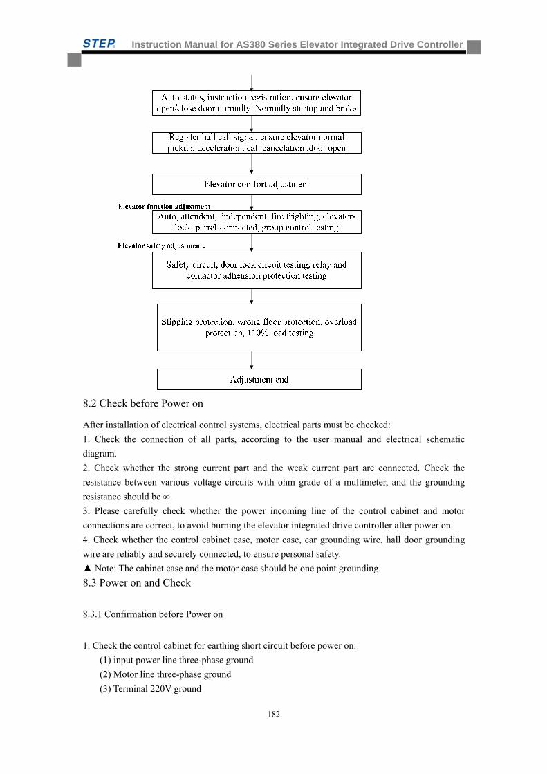
Instruction Manual for AS380 Series Elevator Integrated Drive Controller
182
8.2 Check before Power on
After installation of electrical control systems, electrical parts must be checked:
1. Check the connection of all parts, according to the user manual and electrical schematic
diagram.
2. Check whether the strong current part and the weak current part are connected. Check the
resistance between various voltage circuits with ohm grade of a multimeter, and the grounding
resistance should be ∞.
3. Please carefully check whether the power incoming line of the control cabinet and motor
connections are correct, to avoid burning the elevator integrated drive controller after power on.
4. Check whether the control cabinet case, motor case, car grounding wire, hall door grounding
wire are reliably and securely connected, to ensure personal safety.
Note: The cabinet case and the motor case should be one point grounding.
8.3 Power on and Check
8.3.1 Confirmation before Power on
1. Check the control cabinet for earthing short circuit before power on:
(1) input power line three-phase ground
(2) Motor line three-phase ground
(3) Terminal 220V ground
Instruction Manual for AS380 Series Elevator Integrated Drive Controller
183
(4) Communication line ground
(5) Encoder line ground
Please exclude all items above if short circuited.
2. Grounding check: (Make sure the following items are reliably grounded)
(1) Control cabinet ground
(2) Motor ground
(3) Lift car ground
(4) Door motor ground
(5) wire casing ground
(6) Encoder shield control cabinet ground
(7) Encoder shield motor terminal ground
Note: single terminal grounded for asynchronous motor encoder shield, both terminals
grounded for synchronous motor Encoder shield.
3. Check communication lines, encoder cable and power line wiring: (Please confirm whether the
site meets the following requirements, if not, please correct):
(1) Well communication line is twisted pair line and the twist distance <35cm
(2) Lift car communication line is twisted pair and the twist distance <35cm
(3) Group control communication line of parallel connection is a twisted pair line and the
twist distance<35cm (only parallel connection or group control elevator)
(4) Encoder lines and power lines go separate trunking
(5) Communication lines and power lines go separate trunking
(6) Group control communication lines of parallel connection and power lines go separate
trucking (only parallel connection or group control elevator)
8.3.2 Checks after Power on
1. Close the main power switch. If the green light on the phase sequence relay KAP is on, the phase position is correct. If the green light is not on, shut off the main power supply; swap any two-phase positions and then power on again. 2. Check all terminal voltage of the isolation transformer TCO in the control cabinet, and see whether they are within the nominal range. 3. In the premise of carrying out the above steps correctly, proceed with the following steps: (1) Close the fuse FUn (n = 1, 2, 3 ... ...); (2) Close the door open/close power control switch; open/close TPB is powered on, and the motherboard is electrified to run. Each terminal voltage of switching power supply is as follows:
Table 8.1 Terminal voltage of switching power supply
Terminal L~ N 24V~ COM
voltage 220±7%VAC 24.0±0.3VDC
(3) Reset the emergency stop switch of the control cabinet, connect safety loop, and the LED
lights corresponding to the motherboard input point are on.
(4) Check the following circuit:
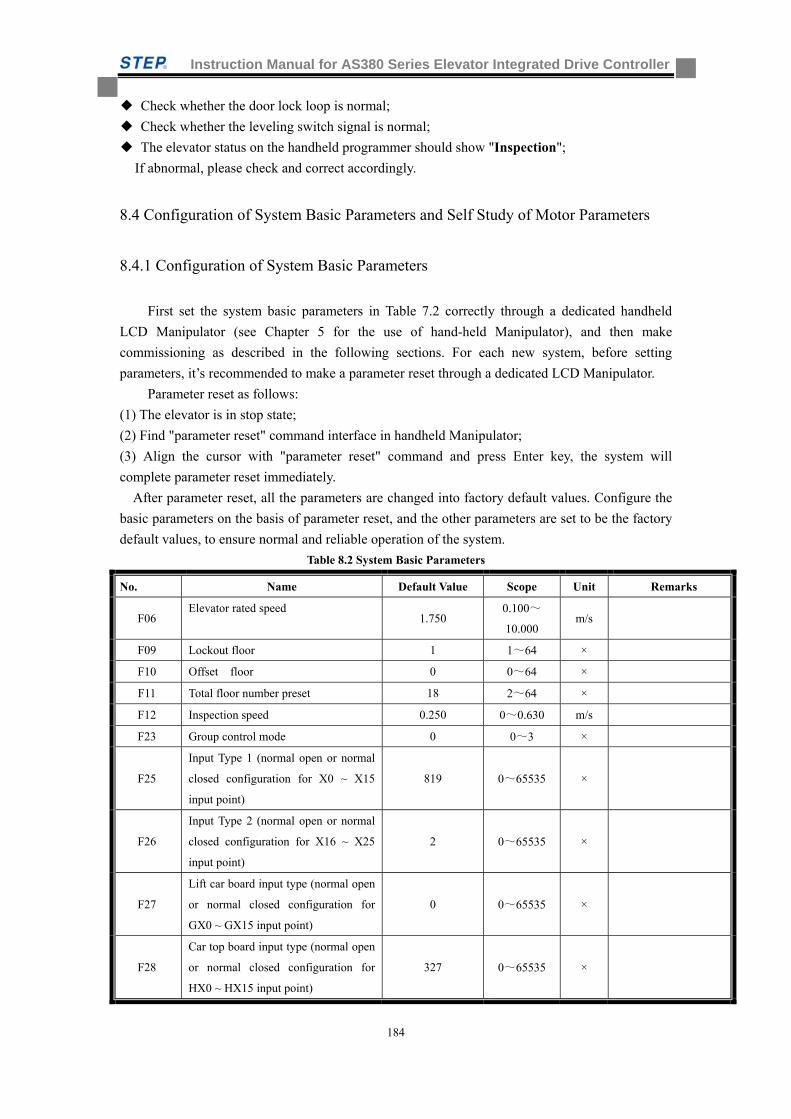
Instruction Manual for AS380 Series Elevator Integrated Drive Controller
184
Check whether the door lock loop is normal;
Check whether the leveling switch signal is normal;
The elevator status on the handheld programmer should show "Inspection";
If abnormal, please check and correct accordingly.
8.4 Configuration of System Basic Parameters and Self Study of Motor Parameters
8.4.1 Configuration of System Basic Parameters
First set the system basic parameters in Table 7.2 correctly through a dedicated handheld
LCD Manipulator (see Chapter 5 for the use of hand-held Manipulator), and then make
commissioning as described in the following sections. For each new system, before setting
parameters, it’s recommended to make a parameter reset through a dedicated LCD Manipulator.
Parameter reset as follows:
(1) The elevator is in stop state;
(2) Find "parameter reset" command interface in handheld Manipulator;
(3) Align the cursor with "parameter reset" command and press Enter key, the system will
complete parameter reset immediately.
After parameter reset, all the parameters are changed into factory default values. Configure the
basic parameters on the basis of parameter reset, and the other parameters are set to be the factory
default values, to ensure normal and reliable operation of the system.
Table 8.2 System Basic Parameters
No. Name Default Value Scope Unit Remarks
F06 Elevator rated speed
1.750 0.100~
10.000 m/s
F09 Lockout floor 1 1~64 ×
F10 Offset floor 0 0~64 ×
F11 Total floor number preset 18 2~64 ×
F12 Inspection speed 0.250 0~0.630 m/s
F23 Group control mode 0 0~3 ×
F25
Input Type 1 (normal open or normal
closed configuration for X0 ~ X15
input point)
819 0~65535 ×
F26
Input Type 2 (normal open or normal
closed configuration for X16 ~ X25
input point)
2 0~65535 ×
F27
Lift car board input type (normal open
or normal closed configuration for
GX0 ~ GX15 input point)
0 0~65535 ×
F28
Car top board input type (normal open
or normal closed configuration for
HX0 ~ HX15 input point)
327 0~65535 ×
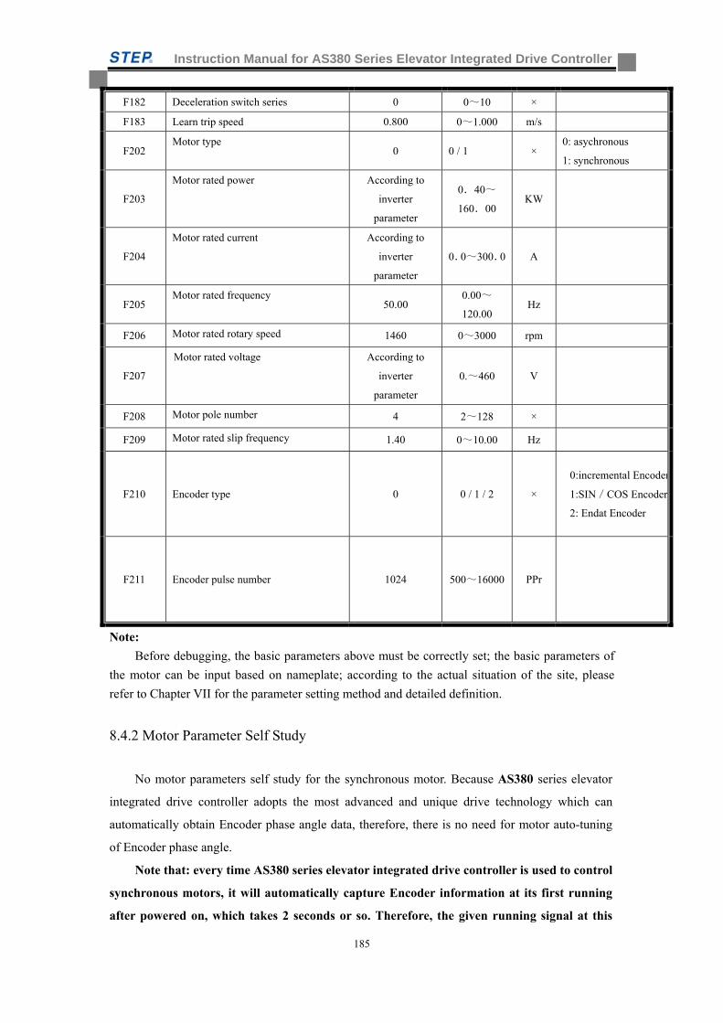
Instruction Manual for AS380 Series Elevator Integrated Drive Controller
185
F182 Deceleration switch series 0 0~10 ×
F183 Learn trip speed 0.800 0~1.000 m/s
F202 Motor type
0 0 / 1 × 0: asychronous
1: synchronous
F203
Motor rated power According to
inverter
parameter
0.40~
160.00 KW
F204
Motor rated current According to
inverter
parameter
0.0~300.0 A
F205 Motor rated frequency
50.00 0.00~
120.00 Hz
F206 Motor rated rotary speed 1460 0~3000 rpm
F207
Motor rated voltage According to
inverter
parameter
0.~460 V
F208 Motor pole number 4 2~128 ×
F209 Motor rated slip frequency 1.40 0~10.00 Hz
F210 Encoder type 0 0 / 1 / 2 ×
0:incremental Encoder
1:SIN/COS Encoder
2: Endat Encoder
F211 Encoder pulse number 1024 500~16000 PPr
Note:
Before debugging, the basic parameters above must be correctly set; the basic parameters of
the motor can be input based on nameplate; according to the actual situation of the site, please
refer to Chapter VII for the parameter setting method and detailed definition.
8.4.2 Motor Parameter Self Study
No motor parameters self study for the synchronous motor. Because AS380 series elevator
integrated drive controller adopts the most advanced and unique drive technology which can
automatically obtain Encoder phase angle data, therefore, there is no need for motor auto-tuning
of Encoder phase angle.
Note that: every time AS380 series elevator integrated drive controller is used to control
synchronous motors, it will automatically capture Encoder information at its first running
after powered on, which takes 2 seconds or so. Therefore, the given running signal at this
Instruction Manual for AS380 Series Elevator Integrated Drive Controller
186
time is slightly later than usual. Please do consider this detail in the design for this control
system, to avoid unnecessary failure.
For the induction motor, if the on-site motor parameters are confirmed to be very accurate, in
particular if the F209 (motor rated slip frequency) parameters are ensured to be accurate, the
following self study of motor internal characteristic parameters will not be necessary. However, if
the on-site motor parameters are not accurate enough, or with the purpose of ensuring excellent
operating characteristics of the system, self study can be carried out on site regarding the motor
internal operating parameters. Specific methods are as follows:
(1) The connections between AS380 series elevator integrated drive controller and motor,
between AIO and encoder have been correctly completed;
(2) Correctly power on for AIO;
(3) Confirm that the safety loop and lock loop are in a normal connected state;
(4) The Auto / Inspection (or emergency power operation) switch is in position of Inspection
(or emergency power operation):
(5) Select "induction motor self study" command by Seven-Segment Code Display
Manipulator or LCD handheld Manipulator, and then press the Enter key;
(6) AIO starts static self study: the main contactor between AIO and the motor will
automatically pull; AIO obtains internal characteristics parameters of the motor by applying
test current on the motor. But the brake contactor will not pull; neither will the motor rotate;
(7) The motor parameters complete their self study after 30 seconds, and the main contactor
releases automatically.
If the self study does not work, mainly check the following items:
(1) Whether the safety loop and the lock loop are connected. If not, the main contactor will
not pull, so it is impossible to complete the self study;
(2) Whether the Encoder wiring is correct, whether A, B phase is reversed;
(3) Whether the motor parameters are set correctly.
8.5 Test Run of Slow Car
8.5.1 Inspection Operation of Engine Room and Preparations for Express Car
1. Points to be confirmed by the engine room before slow car run
(1)Inspection (or emergency power operation) switch of the control cabinet to "Inspection"(or
emergency power operation) position, and car top Inspection switch to "normal " position;
(2)Safety loop and lock loop work properly. Remember not to have lock shorted;
(3)Encoder properly installed and wired correctly;
(4)After powered on, the elevator integrated drive controller displays normally and checks
whether its parameters are set correctly, and manual programming shows that the elevator is
in a status of "Inspection";
Instruction Manual for AS380 Series Elevator Integrated Drive Controller
187
(5)Connect the tractor brake line onto the terminal in the control cabinet correctly;
(6)The upper and lower slow down switches are correctly wired;
(7)Inspection priority circuit on the car top is correctly wired;
2. Operation of engine room slow car
After the engine room slow car meets the operating conditions, press the upward (downward)
button on the control cabinet, and the elevator should go upward (downward) at a preset
Inspection speed.
(1)Observe whether the elevator follows the right direction, when it goes up or down. If in the
wrong direction, first check whether the up and down buttons are correctly wired: JP8.3 of AIO
motherboard should be connected to upward button signal, JP8.4 should be connected to the
downward signal button. If correctly wired, change the F234 motor phase sequence parameters
(from 0 to 1or from 1 to 0).
(2)When the slow car goes upward or downward, if the motor displayed by AIO feedbacks an
unstable speed or gives a value with significant deviation, check the wiring between Encoder and
the motherboard: (1) whether the cable is properly used. If the Encoder is a differential signal, use
shielded twisted-pair cable; if not differential signal, use general shielded cable. (2) Whether the
alignment is reasonable. The Encoder cable and power lines should not go trunking together, and
must be strictly separated from each other (3) Check whether the shielding lines and net are
reliably grounded.
(3)Check whether the upper and lower leveling switches are correctly wired: when the elevator
goes up slowly, X7 (lower leveling switch) motion should be confirmed before passing through
the leveling floor, and X6 (upper leveling switch) motions after. In case of the opposite order, the
well cannot complete self study successfully. In that case, the wiring of the two switches to the
motherboard must be interchanged.
Note: Under many circumstances, slow running is not an Inspection operation, but an
emergency power operation. At this point, in the safety loop, the safety gear switch, limiter
switch, upward over speed protection switch, upper and lower terminal limit switch and
buffer reset switch are all shorted in the slow run mode, to which particular attention should
be paid. It is recommended that the engine room emergency operation should not last too
long in time and distance, and do not have the lift car run to the end position.
8.5.2 Car Top Inspection Operation
After engine room slow car functions normally, you can run the car top Inspection operations.
The Inspection speed may be adjusted appropriately lower in the first overhaul. After the operator
enters into the car top:
(1) First set immediately the car top Auto / Inspection switch to Inspection position, and confirm
that the upward and downward buttons in the control cabinet of the engine room do not
work at this moment.
(2) Press the upward and downward buttons by car top, and confirm that the button direction is
the same with the lift car running direction.
(3) The operator should operate on the car top the elevator for a test run of back and forth,
carefully observe the surrounding of the lift car and confirm that there is no obstruction for
the lift car in the entire well.
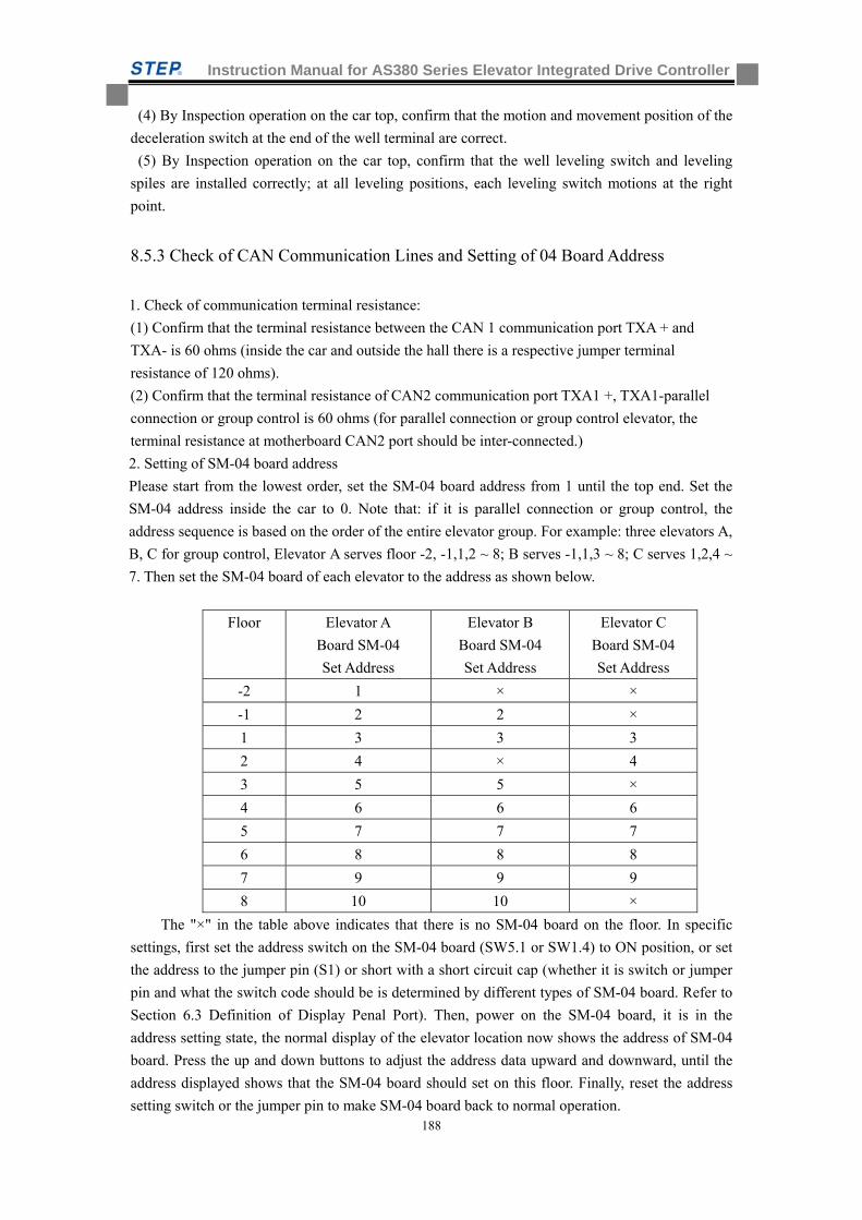
Instruction Manual for AS380 Series Elevator Integrated Drive Controller
188
(4) By Inspection operation on the car top, confirm that the motion and movement position of the
deceleration switch at the end of the well terminal are correct.
(5) By Inspection operation on the car top, confirm that the well leveling switch and leveling
spiles are installed correctly; at all leveling positions, each leveling switch motions at the right
point.
8.5.3 Check of CAN Communication Lines and Setting of 04 Board Address
1. Check of communication terminal resistance:
(1) Confirm that the terminal resistance between the CAN 1 communication port TXA + and
TXA- is 60 ohms (inside the car and outside the hall there is a respective jumper terminal
resistance of 120 ohms).
(2) Confirm that the terminal resistance of CAN2 communication port TXA1 +, TXA1-parallel
connection or group control is 60 ohms (for parallel connection or group control elevator, the
terminal resistance at motherboard CAN2 port should be inter-connected.)
2. Setting of SM-04 board address
Please start from the lowest order, set the SM-04 board address from 1 until the top end. Set the
SM-04 address inside the car to 0. Note that: if it is parallel connection or group control, the
address sequence is based on the order of the entire elevator group. For example: three elevators A,
B, C for group control, Elevator A serves floor -2, -1,1,2 ~ 8; B serves -1,1,3 ~ 8; C serves 1,2,4 ~
7. Then set the SM-04 board of each elevator to the address as shown below.
Floor Elevator A
Board SM-04
Set Address
Elevator B
Board SM-04
Set Address
Elevator C
Board SM-04
Set Address
-2 1 × ×
-1 2 2 ×
1 3 3 3
2 4 × 4
3 5 5 ×
4 6 6 6
5 7 7 7
6 8 8 8
7 9 9 9
8 10 10 ×
The "×" in the table above indicates that there is no SM-04 board on the floor. In specific
settings, first set the address switch on the SM-04 board (SW5.1 or SW1.4) to ON position, or set
the address to the jumper pin (S1) or short with a short circuit cap (whether it is switch or jumper
pin and what the switch code should be is determined by different types of SM-04 board. Refer to
Section 6.3 Definition of Display Penal Port). Then, power on the SM-04 board, it is in the
address setting state, the normal display of the elevator location now shows the address of SM-04
board. Press the up and down buttons to adjust the address data upward and downward, until the
address displayed shows that the SM-04 board should set on this floor. Finally, reset the address
setting switch or the jumper pin to make SM-04 board back to normal operation.
Instruction Manual for AS380 Series Elevator Integrated Drive Controller
189
8.5.4 Door Opening/Closing Adjustment
1. Set the elevator to Inspection status and leave the lift car at the leveling position;
2. Send in door machine power;
3. Move the car door manually, monitor on the handheld Manipulator whether the door closing in
place (HX0) signal and the door opening in place (HX1) signal work correctly;
4. Confirm the safety edge signal and the overload signal are not in action;
5. Confirm F165 parameter set to 0 (door operation allowed during the elevator Inspection);
6. Have the car door in complete open state;
7. Press close button to confirm that the elevator door may close correctly until close in place;
8. Then, press the button to open the door, make sure the elevator door may open correctly until
open in position.
8.6 hoist way Self Study
Running hoist way self study means the elevator runs at self study speed and records the
position of each floor and that of each switch in the well, as the floor location is the basis for the
normal brake and operation of the elevator and for the floor display. Therefore, before the express
car operates, it is mandatory to run well self study first.
8.6.1 Hoist way Self Study Method
1.Confirm the elevator complies with safe operating conditions.
2. Confirm that all switches within the well are correctly installed and wired, and the connection
of accompanying cables and outside cables is correct;
3.Have the elevator into Inspection (or emergency electric operating) state;
4.Enter into self study menu by hand-held programmer, follow the menu instructions, and find
well self study interface. Then move the cursor to well self study command and press Enter key;
5.Set the elevator into the automatic state, and the elevator runs down to the bottom level at s
Learn trip speed (set by F183) and then automatically goes up at self study speed, and begin well
self study. Well study is complete until the elevator arrives at the top leveling position and stops
automatically. The handheld Manipulator shows "self study completed" after the success of the
self study;
6.In the self study process, if the control system is abnormal, self study will stop and give the
corresponding fault number, and the handheld Manipulator shows "self study unsuccessful".
Main reasons for unsuccessful well self study include:
(1)The total story number set (F11) is inconsistent with the number of leveling spiles
installed in the well;
(2)The number of slow down switches installed is inconsistent with the data set by
parameter F182;
(3)The upper and lower leveling switch wiring reversed;
(4)The leveling switch and leveling spiles are installed in the position not accurate enough
to make leveling switch motion effectively and correctly when the leveling spile of each
floor inserts;
Instruction Manual for AS380 Series Elevator Integrated Drive Controller
190
(5)The set norm. Open / norm. closed input of leveling switch is inconsistent with the
actual one;
(6)Wrong motion or wrong installation position of slow down switch (when the lift car is
at the ground floor leveling position, the slow down switch on the lower single level
must motion, before the lift car goes upward to the leveling position of the second
bottom floor, the slow down switch on the lower single level must have been reset; when
the lift car is at the top floor leveling position, the slow down switch on the upper single
level must motion, before the lift car goes downward to the leveling position of the
second top floor, the slow down switch on the upper single level must have been reset).
(7)The set norm. open / norm. closed input of slow down switch is inconsistent with the
actual one;
(8)Encoder signal is interfered or Encoder has wiring error;
(9)Leveling switch signal interfered;
(10)Leveling switch failure or Encoder failure.
Note: in 2 levels / 2 stops self study, run the elevator to the lower limit after it enters
Inspection state. Proceed with normal self study after the upper leveling switch pulls away.
Note: Express car operation is only possible after well self study.
8.7 Express Car Operation
1.Test Run of Express Car
After slow car runs correctly, first make sure the elevator complies with safe operating
conditions. After well self study, proceed with express car test run. Specific steps are as follows:
1) Set the elevator in normal state.
2) Monitor the selected floor by hand-held programmer to select the floor where the elevator runs.
Test run is possible for single floor, double floor, multi floors and full trip.
3) Check whether the elevator can correctly close the door, start, accelerate, run, cut, decelerate,
stop, cancel and open.
4) In case of abnormal operation, follow the fault code (see Chapter IX) and operate accordingly.
2.Safety Test
1) Safety loop
Testing requirements: When the elevator stops, any of the safety switches motions. After safety
loop is disconnected, the elevator can not start; when the elevator is under inspection operation,
any of the safety switches motions. After safety loop is disconnected, the elevator takes an
emergency stop.
2) Door lock loop
Testing requirements: When the elevator stops, after any of the hall door locks is disconnected,
the elevator can not start; when the elevator is under Inspection operation, after any of the hall
door locks is disconnected, the elevator takes an emergency stop.
3) Safety loop relay adhesion protection (This function may not be tested if no safety loop relay)
Testing requirements: Press the emergency stop of control cabinet to disconnect the safety loop,
and then force the safety loop relay not to release by any means. The system should be protected
and not reset automatically;
4) Door lock loop relay adhesion protection (This function may not be tested if no door lock loop
Instruction Manual for AS380 Series Elevator Integrated Drive Controller
191
relay)
Testing requirements: Under door-open circumstances, force the door lock loop relay not to
release by any means. The system should be protected and not reset automatically;
5) Brake contactor adhesion protection
Testing requirements: Under stop circumstances, force the brake contactor not to release by
any means. The system should be protected and not reset automatically;
6) Output contactor normal adhesion protection
Testing requirements: Under stop circumstances, force the brake contactor not to release by
any means. The system should be protected and not reset automatically;
7) Skid protection function
Testing requirements: Move the elevator Inspection to the middle floor, remove the leveling
sensor lines from the control cabinet wiring terminal (assuming leveling floor signal is normal.
open), switch to normal, the elevator goes leveling at low speed, the system protected within 45
seconds and will not reset automatically;
8) Split-level protection
Testing requirements: (1) Move the elevator Inspected to the leveling position of middle floor,
and switch to Inspection or emergency power operation. If the slow down switch is normal closed
contact, disconnect the JP8.5 wiring at the upper single deceleration switch input on the
motherboard; but if it is norm. Open contact, short JP8.5 and JP10.3 (input COM terminal). And
thus create an intentional split-level fault, and then the system will display the top floor data. Then,
change the JP8.5 wiring at the upper single deceleration switch input back to normal, and switch
the elevator to normal state, register the bottom instructions, elevator express car goes down, make
sure the elevator can decelerate and level normally to the bottom floor and does not sink to the
bottom; (2) Move the elevator Inspected to the middle floor, and switch to Inspection or
emergency power operation. If the slow down switch is normal closed contact, disconnect the
JP8.6 wiring at the lower single deceleration switch input on the motherboard; but if it is norm.
open contact, short JP8.6 and JP10.3 (input COM terminal). And thus create an intentional
split-level fault, and then the system will display the bottom floor data. Then, change the JP8.6
wiring at the lower single deceleration switch input back to normal, and switch the elevator to
normal state, register the top instructions, elevator express car goes up, make sure the elevator can
decelerate and level normally to the top floor and does not rush to the top.
9) Overload function
Testing requirements; elevator overload switching, check the elevator should not be closed, the
buzzer sounds inside the car, and the overload indicator light on.
1 Elevator function testing
(1) automatic running
Testing requirement: register several instructions in the car and confirm: elevator can
normally close the door automatically, start, run at high speed, and automatically
decelerate at the nearest registered landing, stop and cancel registration (the instruction
canceled is in consistent with the landing the elevator stop) and open door.
Register several upper or down hall call signals, confirm: elevator can automatically
close the door, start, accelerate, run, cut, decelerate, stop, cancel and open.
(2) attendant running
Instruction Manual for AS380 Series Elevator Integrated Drive Controller
192
Testing requirement: turn the in-car switch to attendant status, and register several
instructions. Keep pressing door-closing button to close the elevator door (if user release
the door open/close button before door closing, the elevator will immediately turn from
door-closing motion into door-opening motion until the door completely open).
Automatically start after door close, run at high speed, and auto decelerate at nearest
registered landing, stop , correctly cancel instruction and auto open door. Register
several upper and down hall call signals ,keep pressing door-closing button until elevator
close door ( if use release the door open/close button before door closing, the elevator
will immediately turn from door-closing motion into door-opening motion until the door
completely open), auto start after door closed, run at high speed, and normally cut,
decelerate, cancel and open.
(3) independent running
testing requirement: turn the in-car switch to individual status, make sure no floor
showed on hall display board(or display floor No with words like “ out of service“
the call button does not work, register instruction in car, and keep pressing door closing
button until elevator door closed,( if user release the door button before door closed, the
elevator will immediately turn from door-closing motion into door-opening motion until
door complete open). Auto start after door closed, run at high speed, and auto decelerate
at nearest floor with instruction registered, and stop, cancel and auto open the door.
(4) Return at fire
Testing requirement: when elevator park at the certain floor other than firefighting return
base station (appointed by F18), turn the switch of base station return at fire into On
position, all registered instructions and call signals will be completely canceled without
any more registration allowed. The elevator will close door immediately, and return to
firefighting base station in express car mode and the elevator open door and be out of
service after auto door opening. When elevator run in the opposite direction of
firefighting base station in express car mode, turn the base station firefighting return
switch into On position. All registered instructions and call signals will be completely
canceled without any more registration allowed. The elevator will park at nearest station
without door open, and return to base station in express car mode and the elevator open
door and be out of service after auto door opening. When elevator run in the direction of
firefighting base station in express car mode, turn the base station firefighting return
switch into On position. All registered instructions and call signals will be completely
canceled without any more registration allowed. The elevator will bypass to the base
station with stop, and elevator open door and be out of service after auto door opening
until firefighting return switch reset and elevator return to normal running status.
(5) firemen operation (only firefighting ladder)
Testing requirement: turn the elevator firemen operation switch into on position, elevator
will immediately enter into emergency return for firefighting base station (appointed by
F18) status. The whole process and motion is complete same as that of the above fire
return. After elevator return to the firefighting base station, stop and open the door,
elevator enter into firemen operation status. At this time, there is no auto door opening or
closing motion automatically. When doing door closing operation in door complete
opening status, keep pressing door-closing button or instruction button, and elevator will
Instruction Manual for AS380 Series Elevator Integrated Drive Controller
193
turn form door closing motion to door opening motion until door completely open. If
closing door by keep pressing instruction button, the corresponding instruction signals
will be registered after door closed. Press the instruction button for other floor in door
closing status, the instruction signal will also be registered. After instruction signal
registered, the elevator will immediately start automatically, run at high speed, and slow
down at the registered floor and stop. Car stop enable all registered instruction signals to
be removed. When car stop with door closed, keep pressing door-opening button to
maintain door open until the door open in place. Once release the door-opening button in
the process of door opening, the elevator will immediately change from door opening
motion into door closing motion until the door is completely closed. The call button will
always out of function in the fireman operation mode. Only when the elevator park at the
firefighting base station, elevator doors open in place and firefighter switch reset, the
elevator can return to normal running status.
(6) group control in duplex (only for elevator in duplex or group control)
Testing requirement: register several hall call signals and confirm the control system will
allocate most recent or convenient elevator to respond registered call signals. When one
elevator responded a call, the same call signals of all elevators in the same floor will be
canceled at the same time. It is not allowed to have two or more than two elevator to
respond the same call signal, to ensure the down call signals of top floor registered
effectively, and enable the nearest or most convenient elevator to respond. When each
elevator in the group has inconsistent service floor, do the following test for the floors
that only some of elevators can park: move the elevator from it original floor to the floor
a little bit far, and move the elevators that can not park at the floor to park at the near
floor. When register call signal for the floor, ensure a nearest elevator in those for that
floor to respond immediately. If base station return function and standby elevator
disperse function is available, make sure that the parking floor location is conform to the
result of required return base station and elevator standby disperse
(7) elevator lock function
Testing requirement: suppose that elevator stop at the floor outside of elevator lock base
station or is running, turn the elevator lock key at base station to the position of elevator
lock. The elevator can erase all registered call signal and will not register any new call
signal. And landing display of the floor extinguishes or shows the words “out of service”.
The elevator will continue to respond instruction (before arrive base station, continue to
accept new instruction registration signal). After finish response of instruction signal,
automatically return to base station, stop car and open door, cut off in-car lighting and fan
power after door complete its opening, delay 10seconds and then close the door. The
elevator then is out of service.
8.8 Adjust Elevator Comfort
8.8.1 Factors Relating to Elevator Comfort in Operation
(1) Electrical factors:
① Operating curve parameters setting: acceleration, deceleration, S curve bend time, start
Instruction Manual for AS380 Series Elevator Integrated Drive Controller
194
brake delay, stop brake delay, etc.;
② Vector control PID parameters: proportional, integral and differential constants, etc.
(2) Mechanical factors: rail verticality, surface roughness, connection, guide shoe tension,
uniformity of steel wire rope tension, etc.
The coordination in the mechanical system is the most fundamental factor to determine the
comfort of the elevator operation; electrical parameters can only cooperate with the mechanical
system, and further improve the comfort. The electrical factor is adjusted by the serial
motherboard parameter and inverter parameter.
If there are problems in mechanical systems affecting the comfort, the serial motherboard
parameter and inverter parameter can only improve comfort, but cannot change the mechanical
defects fundamentally. The commissioning and related technical personnel should pay sufficient
attention to this.
8.8.2 Adjust Elevator Comfort
(I) Adjust Mechanical Factors
1) Slideway:
Slideway surface roughness
Slideway installation verticality
Connections between slideways
The slideway verticality and the parallelism between two slideways should be controlled
within the limits prescribed by the national standard (GB). If the error is too large, it will affect the
elevator comfort in high-speed operation, there will be jitter or oscillation, or the lift car shakes
from left to right in some positions.
The improper connections of slideway will add step feelings to the elevator operation in some
fixed positions.
2) Tension of Guide Shoe
In case the guide shoe is too tight, there will be step feeling, and it will generate brake
feeling at stop; when guide shoe is too loose, the lift car will give shaking feeling.
If the guide shoe is sliding, then a small space should be maintained between the guide
shoe and the slideway. Without the space or even guide shoe rubs the slideway surface, there
will be oscillation or step feeling when the elevator starts and stops.
When commissioning, shake the lift car with your feet from left to right on the car top. It
will be enough if the lift car has an obvious small displacement from left to right.
3) Uniformity of Steel Wire Rope Tension
If the steel wire rope tension is uneven, some ropes will be tight but some loose to cause
jitter or oscillation in the elevator operation, and thus will affect the start, high-speed
operation and stop.
In commissioning, the elevator can be stopped on the middle floor. Pull every steel wire
rope manually with the same force on the car top. If the pull distance is roughly the same, the
steel wire ropes are under the uniform tension; if not, ask the installer to adjust the tension of
steel wire ropes.
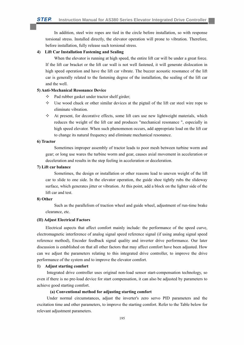
Instruction Manual for AS380 Series Elevator Integrated Drive Controller
195
In addition, steel wire ropes are tied in the circle before installation, so with response
torsional stress. Installed directly, the elevator operation will prone to vibration. Therefore,
before installation, fully release such torsional stress.
4) Lift Car Installation Fastening and Sealing
When the elevator is running at high speed, the entire lift car will be under a great force.
If the lift car bracket or the lift car wall is not well fastened, it will generate dislocation in
high speed operation and have the lift car vibrate. The buzzer acoustic resonance of the lift
car is generally related to the fastening degree of the installation, the sealing of the lift car
and the well.
5) Anti-Mechanical Resonance Device
Pad rubber gasket under tractor shelf girder;
Use wood chuck or other similar devices at the pigtail of the lift car steel wire rope to
eliminate vibration.
At present, for decorative effects, some lift cars use new lightweight materials, which
reduces the weight of the lift car and produces "mechanical resonance ", especially in
high speed elevator. When such phenomenon occurs, add appropriate load on the lift car
to change its natural frequency and eliminate mechanical resonance.
6) Tractor
Sometimes improper assembly of tractor leads to poor mesh between turbine worm and
gear; or long use wares the turbine worm and gear, causes axial movement in acceleration or
deceleration and results in the step feeling in acceleration or deceleration.
7) Lift car balance
Sometimes, the design or installation or other reasons lead to uneven weight of the lift
car to slide to one side. In the elevator operation, the guide shoe tightly rubs the slideway
surface, which generates jitter or vibration. At this point, add a block on the lighter side of the
lift car and test.
8) Other
Such as the parallelism of traction wheel and guide wheel, adjustment of run-time brake
clearance, etc.
(II) Adjust Electrical Factors
Electrical aspects that affect comfort mainly include: the performance of the speed curve,
electromagnetic interference of analog signal speed reference signal (if using analog signal speed
reference method), Encoder feedback signal quality and inverter drive performance. Our later
discussion is established on that all other factors that may affect comfort have been adjusted. How
can we adjust the parameters relating to this integrated drive controller, to improve the drive
performance of the system and to improve the elevator comfort.
1) Adjust starting comfort
Integrated drive controller uses original non-load sensor start-compensation technology, so
even if there is no pre-load device for start compensation, it can also be adjusted by parameters to
achieve good starting comfort.
(a) Conventional method for adjusting starting comfort
Under normal circumstances, adjust the inverter's zero servo PID parameters and the
excitation time and other parameters, to improve the starting comfort. Refer to the Table below for
relevant adjustment parameters.
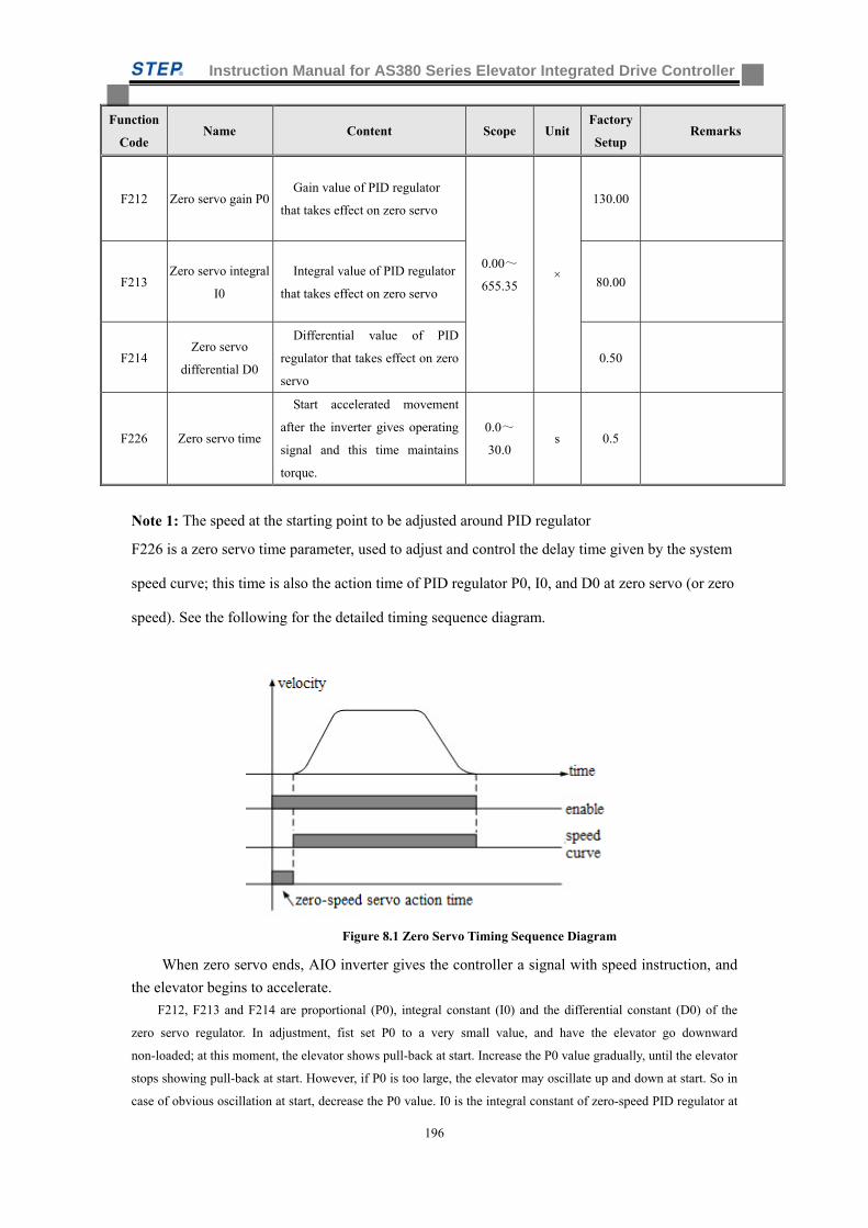
Instruction Manual for AS380 Series Elevator Integrated Drive Controller
196
Function
Code Name Content Scope Unit
Factory
Setup Remarks
F212 Zero servo gain P0 Gain value of PID regulator
that takes effect on zero servo
0.00~
655.35 ×
130.00
F213 Zero servo integral
I0
Integral value of PID regulator
that takes effect on zero servo 80.00
F214 Zero servo
differential D0
Differential value of PID
regulator that takes effect on zero
servo
0.50
F226 Zero servo time
Start accelerated movement
after the inverter gives operating
signal and this time maintains
torque.
0.0~
30.0 s 0.5
Note 1: The speed at the starting point to be adjusted around PID regulator
F226 is a zero servo time parameter, used to adjust and control the delay time given by the system
speed curve; this time is also the action time of PID regulator P0, I0, and D0 at zero servo (or zero
speed). See the following for the detailed timing sequence diagram.
Figure 8.1 Zero Servo Timing Sequence Diagram
When zero servo ends, AIO inverter gives the controller a signal with speed instruction, and
the elevator begins to accelerate.
F212, F213 and F214 are proportional (P0), integral constant (I0) and the differential constant (D0) of the
zero servo regulator. In adjustment, fist set P0 to a very small value, and have the elevator go downward
non-loaded; at this moment, the elevator shows pull-back at start. Increase the P0 value gradually, until the elevator
stops showing pull-back at start. However, if P0 is too large, the elevator may oscillate up and down at start. So in
case of obvious oscillation at start, decrease the P0 value. I0 is the integral constant of zero-speed PID regulator at
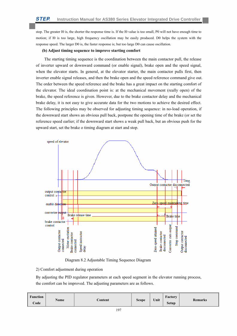
Instruction Manual for AS380 Series Elevator Integrated Drive Controller
197
stop. The greater I0 is, the shorter the response time is. If the I0 value is too small, P0 will not have enough time to
motion; if I0 is too large, high frequency oscillation may be easily produced. D0 helps the system with the
response speed. The larger D0 is, the faster response is; but too large D0 can cause oscillation.
(b) Adjust timing sequence to improve starting comfort
The starting timing sequence is the coordination between the main contactor pull, the release
of inverter upward or downward command (or enable signal), brake open and the speed signal,
when the elevator starts. In general, at the elevator starter, the main contactor pulls first, then
inverter enable signal releases, and then the brake open and the speed reference command give out.
The order between the speed reference and the brake has a great impact on the starting comfort of
the elevator. The ideal coordination point is: at the mechanical movement (really open) of the
brake, the speed reference is given. However, due to the brake contactor delay and the mechanical
brake delay, it is not easy to give accurate data for the two motions to achieve the desired effect.
The following principles may be observed for adjusting timing sequence: in no-load operation, if
the downward start shows an obvious pull back, postpone the opening time of the brake (or set the
reference speed earlier; if the downward start shows a weak pull back, but an obvious push for the
upward start, set the brake o timing diagram at start and stop.
Diagram 8.2 Adjustable Timing Sequence Diagram
2) Comfort adjustment during operation
By adjusting the PID regulator parameters at each speed segment in the elevator running process,
the comfort can be improved. The adjusting parameters are as follows.
Function
Code Name Content Scope Unit
Factory
Setup Remarks
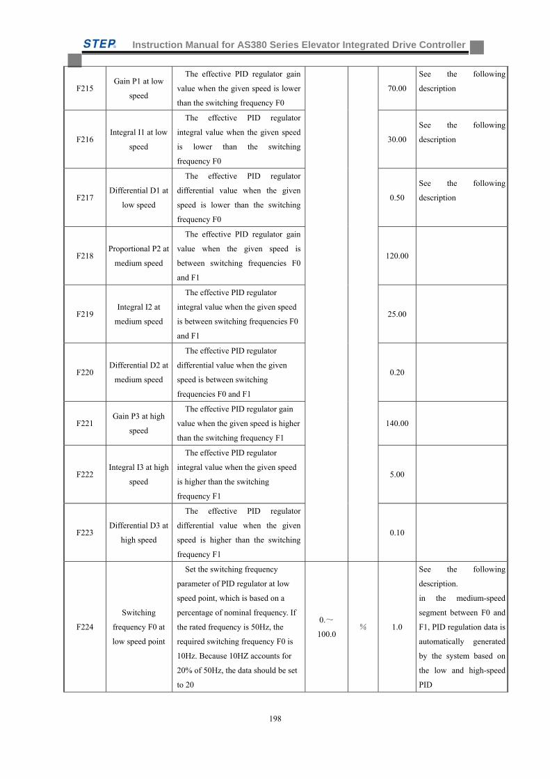
Instruction Manual for AS380 Series Elevator Integrated Drive Controller
198
F215 Gain P1 at low
speed
The effective PID regulator gain
value when the given speed is lower
than the switching frequency F0
70.00
See the following
description
F216 Integral I1 at low
speed
The effective PID regulator
integral value when the given speed
is lower than the switching
frequency F0
30.00
See the following
description
F217 Differential D1 at
low speed
The effective PID regulator
differential value when the given
speed is lower than the switching
frequency F0
0.50
See the following
description
F218 Proportional P2 at
medium speed
The effective PID regulator gain
value when the given speed is
between switching frequencies F0
and F1
120.00
F219 Integral I2 at
medium speed
The effective PID regulator
integral value when the given speed
is between switching frequencies F0
and F1
25.00
F220 Differential D2 at
medium speed
The effective PID regulator
differential value when the given
speed is between switching
frequencies F0 and F1
0.20
F221 Gain P3 at high
speed
The effective PID regulator gain
value when the given speed is higher
than the switching frequency F1
140.00
F222 Integral I3 at high
speed
The effective PID regulator
integral value when the given speed
is higher than the switching
frequency F1
5.00
F223 Differential D3 at
high speed
The effective PID regulator
differential value when the given
speed is higher than the switching
frequency F1
0.10
F224
Switching
frequency F0 at
low speed point
Set the switching frequency
parameter of PID regulator at low
speed point, which is based on a
percentage of nominal frequency. If
the rated frequency is 50Hz, the
required switching frequency F0 is
10Hz. Because 10HZ accounts for
20% of 50Hz, the data should be set
to 20
0.~
100.0 % 1.0
See the following
description.
in the medium-speed
segment between F0 and
F1, PID regulation data is
automatically generated
by the system based on
the low and high-speed
PID
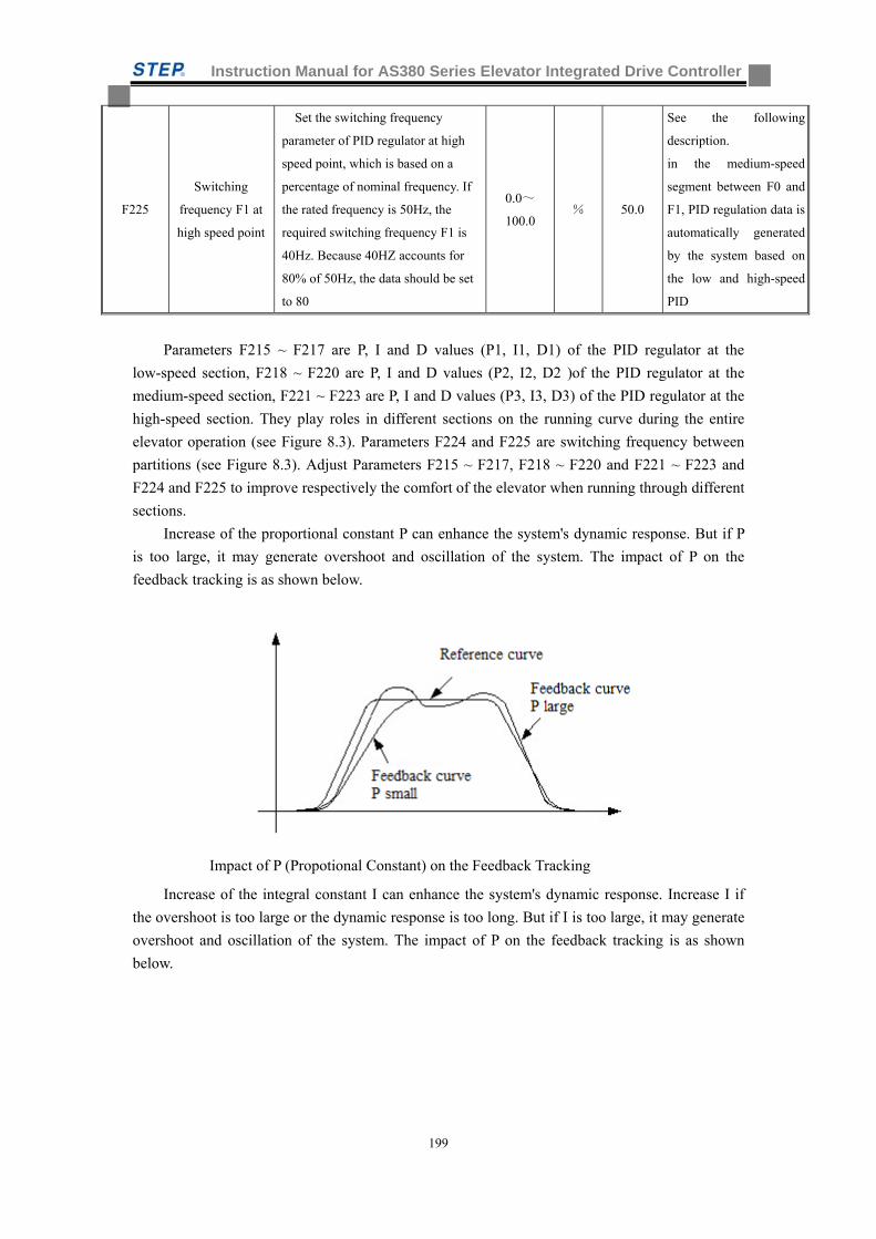
Instruction Manual for AS380 Series Elevator Integrated Drive Controller
199
F225
Switching
frequency F1 at
high speed point
Set the switching frequency
parameter of PID regulator at high
speed point, which is based on a
percentage of nominal frequency. If
the rated frequency is 50Hz, the
required switching frequency F1 is
40Hz. Because 40HZ accounts for
80% of 50Hz, the data should be set
to 80
0.0~
100.0 % 50.0
See the following
description.
in the medium-speed
segment between F0 and
F1, PID regulation data is
automatically generated
by the system based on
the low and high-speed
PID
Parameters F215 ~ F217 are P, I and D values (P1, I1, D1) of the PID regulator at the
low-speed section, F218 ~ F220 are P, I and D values (P2, I2, D2 )of the PID regulator at the
medium-speed section, F221 ~ F223 are P, I and D values (P3, I3, D3) of the PID regulator at the
high-speed section. They play roles in different sections on the running curve during the entire
elevator operation (see Figure 8.3). Parameters F224 and F225 are switching frequency between
partitions (see Figure 8.3). Adjust Parameters F215 ~ F217, F218 ~ F220 and F221 ~ F223 and
F224 and F225 to improve respectively the comfort of the elevator when running through different
sections.
Increase of the proportional constant P can enhance the system's dynamic response. But if P
is too large, it may generate overshoot and oscillation of the system. The impact of P on the
feedback tracking is as shown below.
Impact of P (Propotional Constant) on the Feedback Tracking
Increase of the integral constant I can enhance the system's dynamic response. Increase I if
the overshoot is too large or the dynamic response is too long. But if I is too large, it may generate
overshoot and oscillation of the system. The impact of P on the feedback tracking is as shown
below.
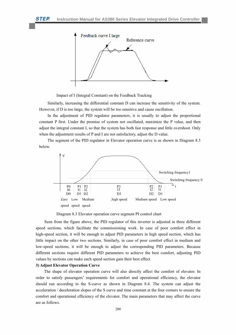
Instruction Manual for AS380 Series Elevator Integrated Drive Controller
200
Impact of I (Integral Constant) on the Feedback Tracking
Similarly, increasing the differential constant D can increase the sensitivity of the system.
However, if D is too large, the system will be too sensitive and cause oscillation.
In the adjustment of PID regulator parameters, it is usually to adjust the proportional
constant P first. Under the premise of system not oscillated, maximize the P value, and then
adjust the integral constant I, so that the system has both fast response and little overshoot. Only
when the adjustment results of P and I are not satisfactory, adjust the D value.
The segment of the PID regulator in Elevator operation curve is as shown in Diagram 8.3
below.
Diagram 8.3 Elevator operation curve segment PI control chart
Seen from the figure above, the PID regulator of this inverter is adjusted in three different
speed sections, which facilitate the commissioning work. In case of poor comfort effect in
high-speed section, it will be enough to adjust PID parameters in high speed section, which has
little impact on the other two sections. Similarly, in case of poor comfort effect in medium and
low-speed sections, it will be enough to adjust the corresponding PID parameters. Because
different sections require different PID parameters to achieve the best comfort, adjusting PID
values by sections can make each speed section gain their best effect.
3) Adjust Elevator Operation Curve
The shape of elevator operation curve will also directly affect the comfort of elevator. In
order to satisfy passengers’ requirements for comfort and operational efficiency, the elevator
should run according to the S-curve as shown in Diagram 8.4. The system can adjust the
acceleration / deceleration slopes of the S curve and time constant at the four corners to ensure the
comfort and operational efficiency of the elevator. The main parameters that may affect the curve
are as follows.
V
P0I0
P1 P2 P3 P1P2I1 I2 I3 I1I2
D0 D1 D1D2 D2D3
t
Low speedMedium speed
Switching frequency1
Switching frequency 0
Zero
speed
Low
speed
Medium
speed
¸high speed
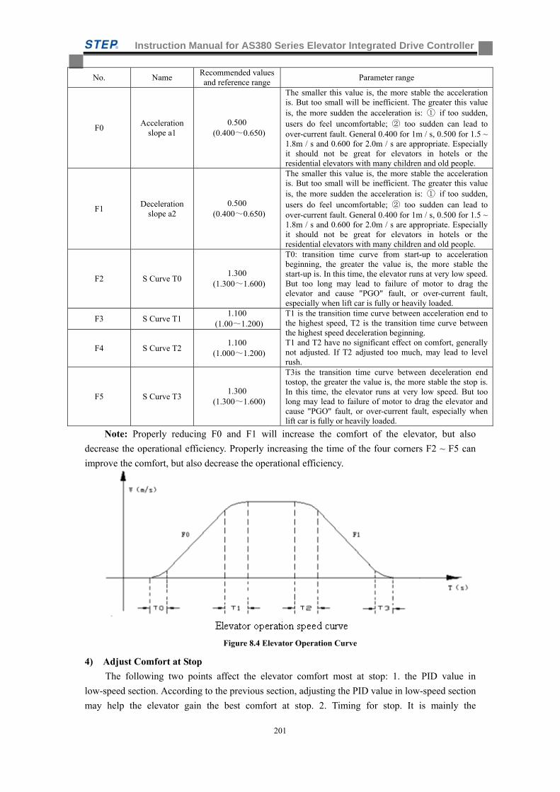
Instruction Manual for AS380 Series Elevator Integrated Drive Controller
201
No. Name Recommended values and reference range
Parameter range
F0 Acceleration
slope a1 0.500
(0.400~0.650)
The smaller this value is, the more stable the acceleration is. But too small will be inefficient. The greater this value is, the more sudden the acceleration is: ① if too sudden, users do feel uncomfortable; ② too sudden can lead to over-current fault. General 0.400 for 1m / s, 0.500 for 1.5 ~ 1.8m / s and 0.600 for 2.0m / s are appropriate. Especially it should not be great for elevators in hotels or the residential elevators with many children and old people.
F1 Deceleration
slope a2 0.500
(0.400~0.650)
The smaller this value is, the more stable the acceleration is. But too small will be inefficient. The greater this value is, the more sudden the acceleration is: ① if too sudden, users do feel uncomfortable; ② too sudden can lead to over-current fault. General 0.400 for 1m / s, 0.500 for 1.5 ~ 1.8m / s and 0.600 for 2.0m / s are appropriate. Especially it should not be great for elevators in hotels or the residential elevators with many children and old people.
F2 S Curve T0 1.300
(1.300~1.600)
T0: transition time curve from start-up to acceleration beginning, the greater the value is, the more stable the start-up is. In this time, the elevator runs at very low speed. But too long may lead to failure of motor to drag the elevator and cause "PGO" fault, or over-current fault, especially when lift car is fully or heavily loaded.
F3 S Curve T1 1.100
(1.00~1.200) T1 is the transition time curve between acceleration end to the highest speed, T2 is the transition time curve between the highest speed deceleration beginning. T1 and T2 have no significant effect on comfort, generally not adjusted. If T2 adjusted too much, may lead to level rush.
F4 S Curve T2 1.100
(1.000~1.200)
F5 S Curve T3 1.300
(1.300~1.600)
T3is the transition time curve between deceleration end tostop, the greater the value is, the more stable the stop is. In this time, the elevator runs at very low speed. But too long may lead to failure of motor to drag the elevator and cause "PGO" fault, or over-current fault, especially when lift car is fully or heavily loaded.
Note: Properly reducing F0 and F1 will increase the comfort of the elevator, but also
decrease the operational efficiency. Properly increasing the time of the four corners F2 ~ F5 can
improve the comfort, but also decrease the operational efficiency.
Figure 8.4 Elevator Operation Curve
4) Adjust Comfort at Stop
The following two points affect the elevator comfort most at stop: 1. the PID value in
low-speed section. According to the previous section, adjusting the PID value in low-speed section
may help the elevator gain the best comfort at stop. 2. Timing for stop. It is mainly the
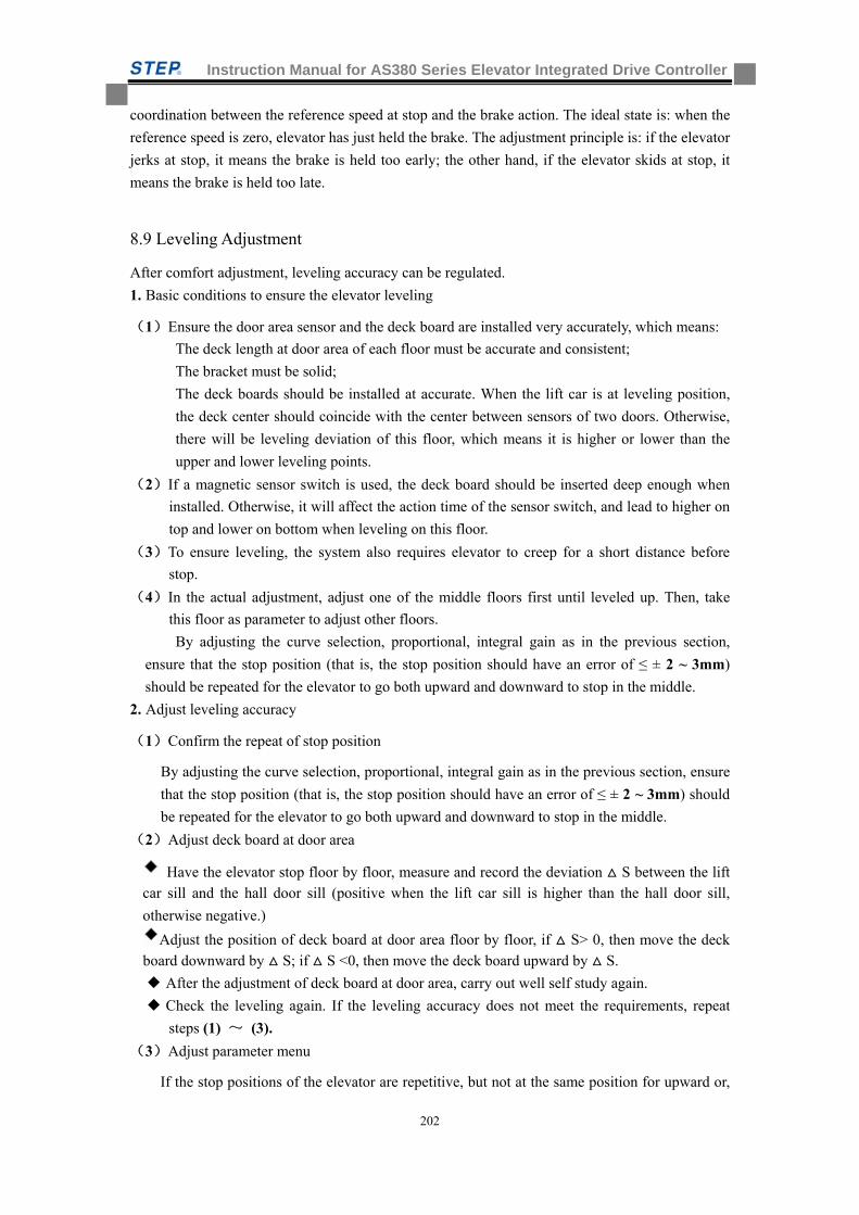
Instruction Manual for AS380 Series Elevator Integrated Drive Controller
202
coordination between the reference speed at stop and the brake action. The ideal state is: when the
reference speed is zero, elevator has just held the brake. The adjustment principle is: if the elevator
jerks at stop, it means the brake is held too early; the other hand, if the elevator skids at stop, it
means the brake is held too late.
8.9 Leveling Adjustment
After comfort adjustment, leveling accuracy can be regulated.
1. Basic conditions to ensure the elevator leveling
(1)Ensure the door area sensor and the deck board are installed very accurately, which means:
The deck length at door area of each floor must be accurate and consistent;
The bracket must be solid;
The deck boards should be installed at accurate. When the lift car is at leveling position,
the deck center should coincide with the center between sensors of two doors. Otherwise,
there will be leveling deviation of this floor, which means it is higher or lower than the
upper and lower leveling points.
(2)If a magnetic sensor switch is used, the deck board should be inserted deep enough when
installed. Otherwise, it will affect the action time of the sensor switch, and lead to higher on
top and lower on bottom when leveling on this floor.
(3)To ensure leveling, the system also requires elevator to creep for a short distance before
stop.
(4)In the actual adjustment, adjust one of the middle floors first until leveled up. Then, take
this floor as parameter to adjust other floors.
By adjusting the curve selection, proportional, integral gain as in the previous section,
ensure that the stop position (that is, the stop position should have an error of ≤ ± 2 ~ 3mm)
should be repeated for the elevator to go both upward and downward to stop in the middle.
2. Adjust leveling accuracy
(1)Confirm the repeat of stop position
By adjusting the curve selection, proportional, integral gain as in the previous section, ensure
that the stop position (that is, the stop position should have an error of ≤ ± 2 ~ 3mm) should
be repeated for the elevator to go both upward and downward to stop in the middle.
(2)Adjust deck board at door area
Have the elevator stop floor by floor, measure and record the deviation S between the lift car sill and the hall door sill (positive when the lift car sill is higher than the hall door sill,
otherwise negative.)
Adjust the position of deck board at door area floor by floor, if S> 0, then move the deck board downward by S; if S <0, then move the deck board upward by S.
After the adjustment of deck board at door area, carry out well self study again.
Check the leveling again. If the leveling accuracy does not meet the requirements, repeat
steps (1) ~ (3).
(3)Adjust parameter menu
If the stop positions of the elevator are repetitive, but not at the same position for upward or,
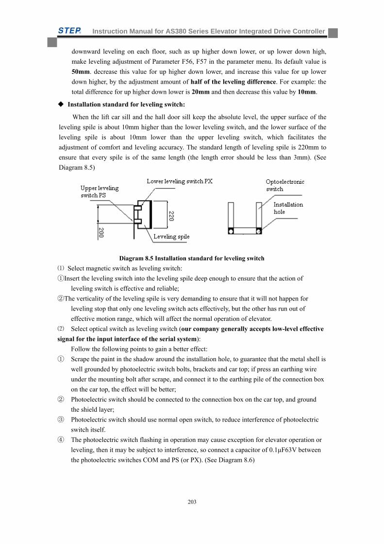
Instruction Manual for AS380 Series Elevator Integrated Drive Controller
203
downward leveling on each floor, such as up higher down lower, or up lower down high,
make leveling adjustment of Parameter F56, F57 in the parameter menu. Its default value is
50mm. decrease this value for up higher down lower, and increase this value for up lower
down higher, by the adjustment amount of half of the leveling difference. For example: the
total difference for up higher down lower is 20mm and then decrease this value by 10mm.
Installation standard for leveling switch:
When the lift car sill and the hall door sill keep the absolute level, the upper surface of the
leveling spile is about 10mm higher than the lower leveling switch, and the lower surface of the
leveling spile is about 10mm lower than the upper leveling switch, which facilitates the
adjustment of comfort and leveling accuracy. The standard length of leveling spile is 220mm to
ensure that every spile is of the same length (the length error should be less than 3mm). (See
Diagram 8.5)
Diagram 8.5 Installation standard for leveling switch
⑴ Select magnetic switch as leveling switch:
①Insert the leveling switch into the leveling spile deep enough to ensure that the action of
leveling switch is effective and reliable;
②The verticality of the leveling spile is very demanding to ensure that it will not happen for
leveling stop that only one leveling switch acts effectively, but the other has run out of
effective motion range, which will affect the normal operation of elevator.
⑵ Select optical switch as leveling switch (our company generally accepts low-level effective
signal for the input interface of the serial system): Follow the following points to gain a better effect:
① Scrape the paint in the shadow around the installation hole, to guarantee that the metal shell is
well grounded by photoelectric switch bolts, brackets and car top; if press an earthing wire
under the mounting bolt after scrape, and connect it to the earthing pile of the connection box
on the car top, the effect will be better;
② Photoelectric switch should be connected to the connection box on the car top, and ground
the shield layer;
③ Photoelectric switch should use normal open switch, to reduce interference of photoelectric
switch itself.
④ The photoelectric switch flashing in operation may cause exception for elevator operation or
leveling, then it may be subject to interference, so connect a capacitor of 0.1μF63V between
the photoelectric switches COM and PS (or PX). (See Diagram 8.6)
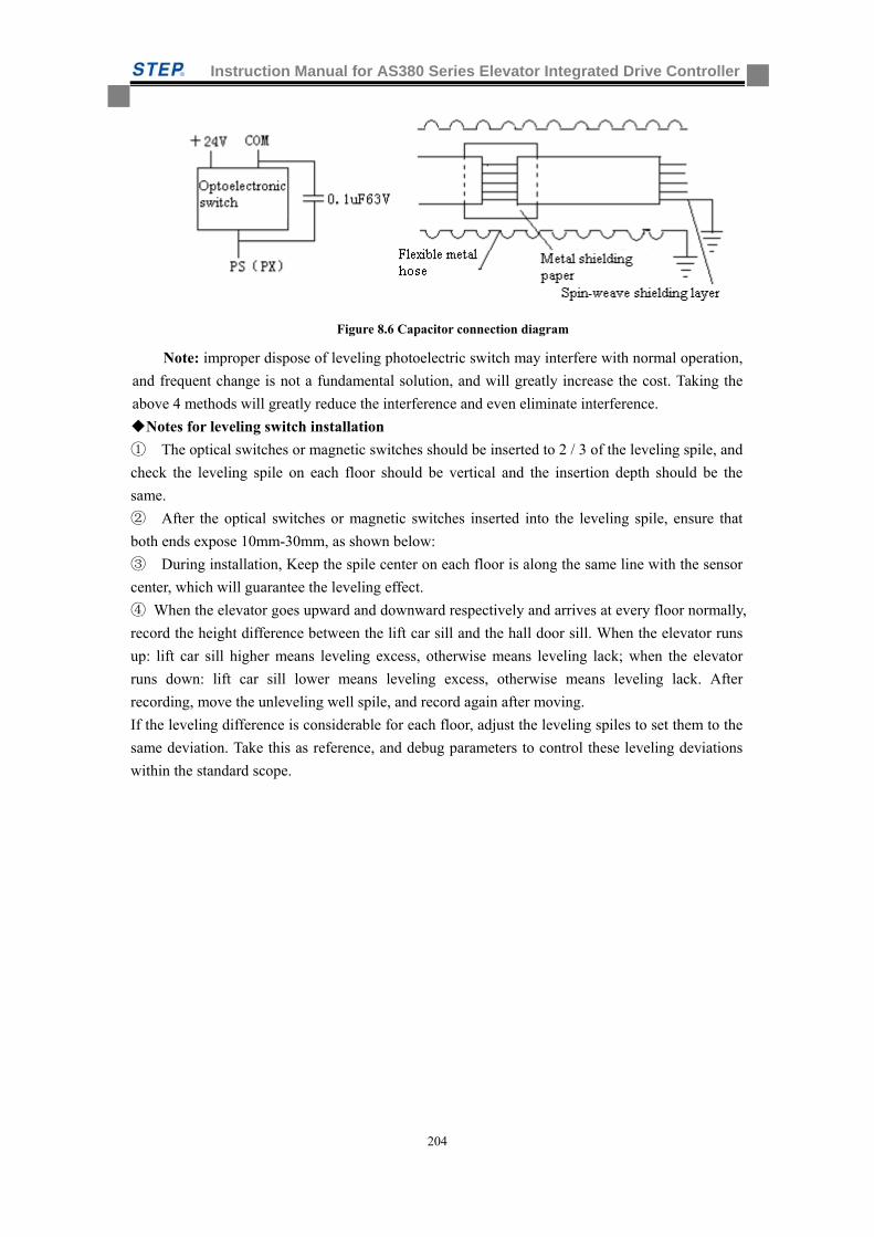
Instruction Manual for AS380 Series Elevator Integrated Drive Controller
204
Figure 8.6 Capacitor connection diagram
Note: improper dispose of leveling photoelectric switch may interfere with normal operation,
and frequent change is not a fundamental solution, and will greatly increase the cost. Taking the
above 4 methods will greatly reduce the interference and even eliminate interference.
Notes for leveling switch installation
① The optical switches or magnetic switches should be inserted to 2 / 3 of the leveling spile, and
check the leveling spile on each floor should be vertical and the insertion depth should be the
same.
② After the optical switches or magnetic switches inserted into the leveling spile, ensure that
both ends expose 10mm-30mm, as shown below:
③ During installation, Keep the spile center on each floor is along the same line with the sensor
center, which will guarantee the leveling effect.
④ When the elevator goes upward and downward respectively and arrives at every floor normally,
record the height difference between the lift car sill and the hall door sill. When the elevator runs
up: lift car sill higher means leveling excess, otherwise means leveling lack; when the elevator
runs down: lift car sill lower means leveling excess, otherwise means leveling lack. After
recording, move the unleveling well spile, and record again after moving.
If the leveling difference is considerable for each floor, adjust the leveling spiles to set them to the
same deviation. Take this as reference, and debug parameters to control these leveling deviations
within the standard scope.
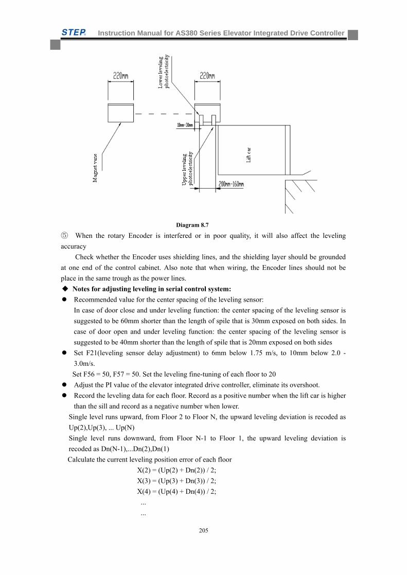
Instruction Manual for AS380 Series Elevator Integrated Drive Controller
205
Diagram 8.7
⑤ When the rotary Encoder is interfered or in poor quality, it will also affect the leveling
accuracy
Check whether the Encoder uses shielding lines, and the shielding layer should be grounded
at one end of the control cabinet. Also note that when wiring, the Encoder lines should not be
place in the same trough as the power lines.
Notes for adjusting leveling in serial control system:
Recommended value for the center spacing of the leveling sensor:
In case of door close and under leveling function: the center spacing of the leveling sensor is
suggested to be 60mm shorter than the length of spile that is 30mm exposed on both sides. In
case of door open and under leveling function: the center spacing of the leveling sensor is
suggested to be 40mm shorter than the length of spile that is 20mm exposed on both sides
Set F21(leveling sensor delay adjustment) to 6mm below 1.75 m/s, to 10mm below 2.0 -
3.0m/s.
Set F56 = 50, F57 = 50. Set the leveling fine-tuning of each floor to 20
Adjust the PI value of the elevator integrated drive controller, eliminate its overshoot.
Record the leveling data for each floor. Record as a positive number when the lift car is higher
than the sill and record as a negative number when lower.
Single level runs upward, from Floor 2 to Floor N, the upward leveling deviation is recoded as
Up(2),Up(3), ... Up(N)
Single level runs downward, from Floor N-1 to Floor 1, the upward leveling deviation is
recoded as Dn(N-1),...Dn(2),Dn(1)
Calculate the current leveling position error of each floor
X(2) = (Up(2) + Dn(2)) / 2;
X(3) = (Up(3) + Dn(3)) / 2;
X(4) = (Up(4) + Dn(4)) / 2;
...
...
Instruction Manual for AS380 Series Elevator Integrated Drive Controller
206
X (N-1) = (Up (N-1) + Dn (N-1)) / 2;
If the deviation of X(2)~X(N-1) exceeds 10 mm, please adjust spile , a positive X(n) means
the spile of this floor is too high; a negative X(n) means the spile of this floor is too low. If
the deviation is less than 10mm, adjust with leveling fine-tuning software.
After rough adjustment for spile, carry out well self study again, and record leveling data.
Single level runs upward, from Floor 2 to Floor N, the upward leveling deviation is recoded as
Up(2),Up(3), ... Up(N)
Single level runs downward, from Floor N-1 to Floor 1, the upward leveling deviation is
recoded as Dn(N-1),...Dn(2),Dn(1)
1) Calculate the current leveling position error of each floor
X(2) = (Up(2) + Dn(2)) / 2;
X(3) = (Up(3) + Dn(3)) / 2;
X(4) = (Up(4) + Dn(4)) / 2;
...
...
X(N-1) = (Up(N-1) + Dn(N-1)) / 2;
2) Calculate the current average offset XUp, XDn; end station is not included
Upward average offset XUp = (Up(2) + Up(3) + ... + Up(N-1)) / (N-2);
Downward average offset XDn = (Dn(2) + Dn(3) + ... + Dn(N-1)) / (N-2);
Central position pX = (XUp - XDn) / 2;
Note: XUp, XDn, pX are operations with symbols
3) Adjust F56, F57:
F56 = 50 - pX;
F57 = 50 - pX;
4) Adjust leveling fine-tuning, record the leveling fine-tuning data of the Nth floor to Ln
L(2) = 20 - X(2)
L(3) = 20 - X(3)
...
L(n) = 20 - X(n)
...
L(N-1) = 20 - X(N-1)
Calculate the leveling fine-tuning of the end station
Reasons why leveling cannot be adjusted:
There may be the following questions, please check in order:
1.The following parameters will lead to improper leveling adjustment if not reasonably
configured
Check F21 (leveling sensor delay adjustment), the factory value: 6 mm. Below 1.75m / s, it can
be set to 6mm when the elevator uses optical leveling sensor
It can be set to 10 mm when the high-speed elevator (3.0m / s or above) uses optical leveling
sensor
It can be set to 16 mm when the high-speed elevator (5.0m / s or above) uses optical leveling
sensor
F56 upward leveling adjustment, factory value: 50 mm
F57 downward leveling adjustment, factory value: 50 mm
Instruction Manual for AS380 Series Elevator Integrated Drive Controller
207
Leveling fine-tuning: set the leveling fine-tuning of each floor to factory default: 20 mm
2. Encoder interference
1) Encoder shielded wire is not grounded, or the signal lines and power lines are not
separated, or interfered by power lines. This problem is very serious on the synchronous motor
site. Sincos Encoder or resolver is small analog signal, more vulnerable to interference, which is
reflected by random irregular unleveling.
2) Check methods: record the well data (from the bottom to the top) after self study, re-start
well self study, compare the two self study data, with a corresponding position error of less than
3mm (usually identical or difference of + - 1mm), error of more than 3 mm can be regarded as
Encoder interfere or traction wheel skid.
3) Solutions:
a) Confirm that the motor ground wire has been connected from the motor to the control
cabinet
b) Confirm that the shielding line from Encoder to the inverter PG card has been
grounded at the inverter end. Check whether this grounding line has intermediate connection
terminal. If any, make sure both ends of the shielding lines are grounded. Note: the connection of
the synchronous motor Sincos Encoder!!!
c) Confirm that the shielding line from the inverter PG Card to the motherboard Encoder
has been grounded
d) Confirm the Encoder lines separated from power lines and braking resistor lines (cover
the Encoder lines with flexible conduit if in the same groove)
e) Confirm that the 0V of PG card is connected with the 0V of the motherboard (in
particular, in multi-speed A +, A-, B +, B-output)
f) Check whether connecting shaft of Encoder skids
3. Steel wire rope of traction wheel slips
1) Phenomenon: the leveling is not accurate in case of operation with no-load or full load, or
the upward leveling is inconsistent with downward leveling, half-load operation leveling is
accurate.
2) Check method: at any floor (assumed to be Floor 3), mark an aligning chalk line between
the steel wire rope and the traction wheel, run a single level back and forth layer (Floor 3 ->
Floor 4, Floor 4 to Floor 3), and back to Floor 3, check the error distance with the chalk mark
(required to be less than 5mm). This error distance is the slip error for a single level. The slip
error should be done twice respectively in no load and full load. All slip error greater than 5 mm
must be resolved.
3) Solution
a) There may be a 200Kg weight difference for the lift car before and after decoration.
Has the lift car decoration finished? Is the current balance coefficient correct? If not sure, set the
lift car to half loaded, is there still leveling error?
b) If it is impossible to resolve the slipping problem for high-speed elevator, there are
two solutions as follows:
1. Install Encoder on one side of the speed governor to feedback the position to the
motherboard
2. Use creeping to absorb slip error, set F24 = 2 (analog signal with creeping) or F24 = 0
(multi-speed operation)
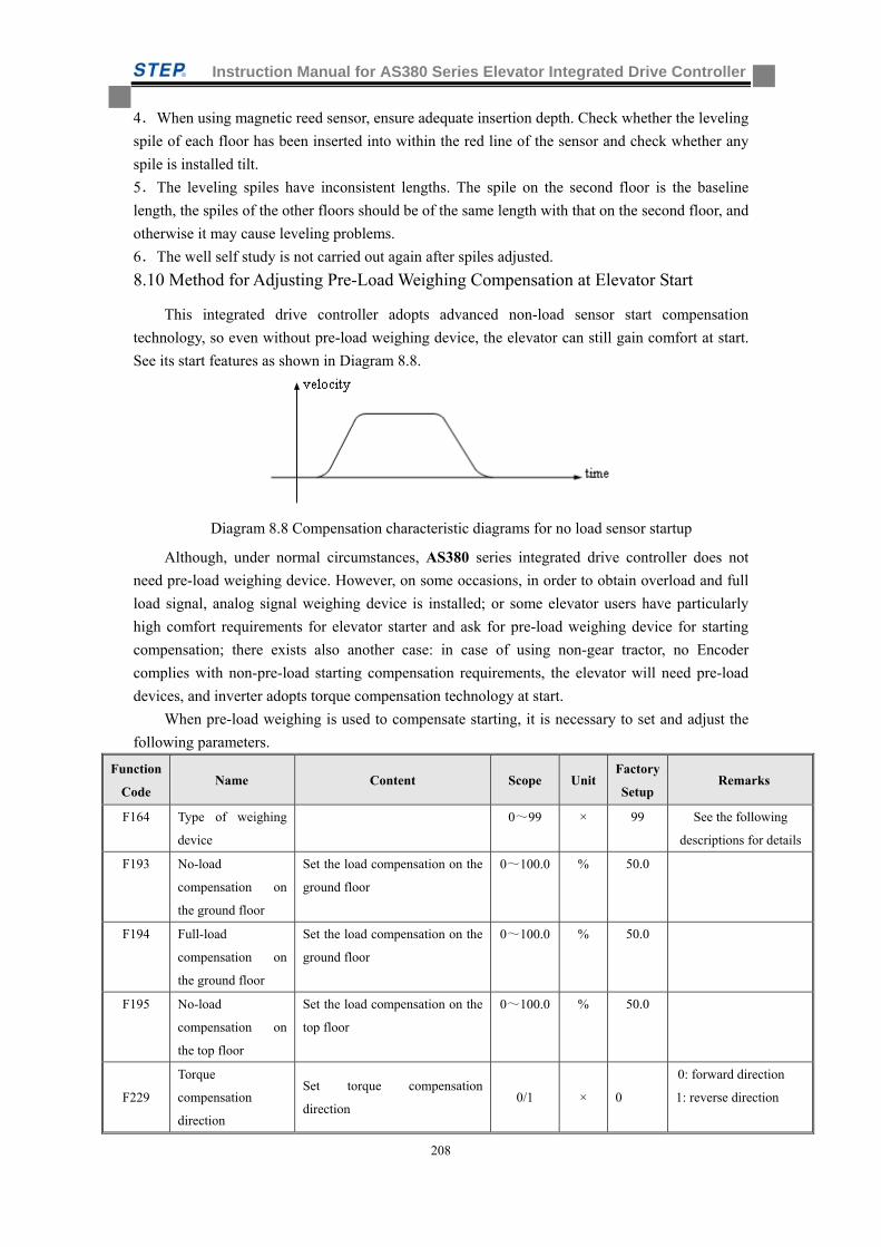
Instruction Manual for AS380 Series Elevator Integrated Drive Controller
208
4.When using magnetic reed sensor, ensure adequate insertion depth. Check whether the leveling
spile of each floor has been inserted into within the red line of the sensor and check whether any
spile is installed tilt.
5.The leveling spiles have inconsistent lengths. The spile on the second floor is the baseline
length, the spiles of the other floors should be of the same length with that on the second floor, and
otherwise it may cause leveling problems.
6.The well self study is not carried out again after spiles adjusted.
8.10 Method for Adjusting Pre-Load Weighing Compensation at Elevator Start
This integrated drive controller adopts advanced non-load sensor start compensation
technology, so even without pre-load weighing device, the elevator can still gain comfort at start.
See its start features as shown in Diagram 8.8.
Diagram 8.8 Compensation characteristic diagrams for no load sensor startup
Although, under normal circumstances, AS380 series integrated drive controller does not
need pre-load weighing device. However, on some occasions, in order to obtain overload and full
load signal, analog signal weighing device is installed; or some elevator users have particularly
high comfort requirements for elevator starter and ask for pre-load weighing device for starting
compensation; there exists also another case: in case of using non-gear tractor, no Encoder
complies with non-pre-load starting compensation requirements, the elevator will need pre-load
devices, and inverter adopts torque compensation technology at start.
When pre-load weighing is used to compensate starting, it is necessary to set and adjust the
following parameters.
Function
Code Name Content Scope Unit
Factory
Setup Remarks
F164 Type of weighing
device
0~99 × 99 See the following
descriptions for details
F193 No-load
compensation on
the ground floor
Set the load compensation on the
ground floor
0~100.0 % 50.0
F194 Full-load
compensation on
the ground floor
Set the load compensation on the
ground floor
0~100.0 % 50.0
F195 No-load
compensation on
the top floor
Set the load compensation on the
top floor
0~100.0 % 50.0
F229
Torque
compensation
direction
Set torque compensation
direction 0/1 × 0
0: forward direction
1: reverse direction
Instruction Manual for AS380 Series Elevator Integrated Drive Controller
209
F230 Torque
compensation gain Set torque compensation gain
0.0~
200.0 % 100.0
F231 Torque
compensation bias Set torque compensation bias
0.0~
100.0 % 0.0
Parameter F164 has the meanings as follows:
F164 set value Model of weighing
device
Acquisition method of light, heavy, full
and over load signal
Acquisition method of compensation
signal
0 DTZZ-III-DC-SC Input open/close signal to the car top
board
Input weighing device signal by CAN,
and then calculate the final
compensation value by weighing device
signal, F193, F194 and F195 parameters
1 DTZZ-II Input weighing device signal by CAN,
and then calculate the result by weighing
device signal
Input weighing device signal by CAN
2 DTZZ-II Input open/close signal to the car top
board
Input weighing device signal by CAN
3 DTZZ-III-DC-SC Input weighing device signal by CAN,
and then calculate the result by weighing
device signal
Input weighing device signal by CAN,
and then calculate the final
compensation value by weighing device
signal, F193, F194 and F195 parameters
4 None Input open/close signal to the car top
board
Calculate the weighing compensation
values at light load and heavy load by
light/heavy switch signal, F193, F194
and F195 parameters, and 40 is set to be
50% at this time.
5 Input open/close signal to the car top
board
Input weighing device signal by analog
signal
6 Input weighing device signal by analog
signal, and then calculate the result by
weighing device signal
Input weighing device signal by analog
signal
99 Input open/close signal to the car top
board
None
Different types of weighing devices correspond to three different adjustment methods: the
first is use of DTZZ-III-DC-SC weighing device (F164 set to 0 or 3); the second is Use of
non-DTZZ-III-DC-SC weighing device (F164 set to 1, 2, 5 or 6); the third is without weighing
device, a simple compensation by using light-load and heavy-load switch. The following three
sections make a detailed introduction on how to adjust the three parameters F193 ~ F195 or 229 ~
F231 in the three start compensating methods. In the absence of start compensation, the four
parameters F164, F193 ~ F195 do not need to be set, and their default value 0 will be ok; the three
parameters 229 ~ F231 can also use their default values.
Instruction Manual for AS380 Series Elevator Integrated Drive Controller
210
8.10.1 Use of DTZZ-III-DC-SC
Use of DTZZ-III-DC-SC weighing device (F164 set to 0 or 3) to compensate or adjust the start.
When DTZZ-III-DC-SC model weighing device is chosen, its weighing data is sent to the
control system in AS380 series AIO via CAN communications. Based on the values of the three
adjustment parameters F193 ~ F195, the control system calculates the final exact compensation
data to the inverter in AIO, and the inverter makes torque starting compensation directly based on
this data. Therefore, in this case, it is enough to adjust only the three parameters F193 ~ F195.
In adjustment, set DTZZ-III-DC-SC model weighing device via Parameter F41 and carry out
self study. The meaning of Parameter F41 is as follows:
F41 Value Meaning
1 No load self study command, the return data after the no load self study is successful
2 Full load self study command, the return data after the full load self study is
successful
10 When the activity of weighing device sensor ranges within 0 ~ 10mm , parameter set
command and the return data after successful self study
20 When the activity of weighing device sensor ranges within 0~20mm , parameter set
command and the return data after successful self study
30 When the activity of weighing device sensor ranges within 0~30mm , parameter set
command and the return data after successful self study
40 When the activity of weighing device sensor ranges within 10mm~0mm , parameter
set command and the return data after successful self study
50 When the activity of weighing device sensor ranges within 20mm~0mm , parameter
set command and the return data after successful self study
60 When the activity of weighing device sensor ranges within 30mm~0mm , parameter
set command and the return data after successful self study
Step 1, based on the actual activity scope of the device, set a correct data in 10~60 by F41;
Step 2, have lift car no-loaded, set F41 to 1, the weighing device carries out no-load self study.
After the self study completes successfully, F41 displays 1; Step 3, have lift car full-loaded, set
F41 to 2, the weighing device carries out full-load self study. After the self study completes
successfully, F41 displays 1. After these three steps, the self study of the weighing device ends.
Then, confirm whether the compensation direction is correct: if the increase of F194 may
reduce the downward impact oscillation of the lift car at start (slipping back when start upward or
rushing when start downward), it means the compensation direction is correct; otherwise, it means
the compensation direction is wrong. If wrong, change the value of Parameter F229 (from 0 to 1,
or from 1 to 0)
After confirming the compensation direction, you can adjust the three parameters F193~
F195. Firstly , run the full-load lift car to the leveling position of the bottom floor, leave the
elevator in Inspection status, set the Inspection speed (F12) to 0, adjust the value of F194 (bottom
full-load compensation) so that the lift car can maintain motionless when the Inspection starts.
During the adjustment, if the lift car moves downward at start, increase F194; if downward,
decrease F194, until the lift car does not motion when the Inspection starts. Then leave the lift car
no-loaded and stay at the leveling position of the bottom floor. Adjust the value of F193 (bottom
Instruction Manual for AS380 Series Elevator Integrated Drive Controller
211
no-load compensation) so that the lift car can maintain motionless when the Inspection starts.
During the adjustment, if the lift car moves downward at start, increase F193; if downward,
decrease F193, until the lift car does not motion when the Inspection starts. In the end, adjust
Parameter F195 (top no-load compensation) so that the non-load lift car can maintain at top
leveling position. Then set the inspection speed (F12) to 0, adjust the F195 (top floor non-load
compensation) value to make car maintain static at inspection start. During the adjustment, if the
lift car moves downward at start, increase F195; if downward, decrease F195, until the lift car
does not motion when the Inspection starts. After the adjustment completes, reset F12 Inspection
speed parameter back to normal data.
8.10.2 Use of non-DTZZ-III-DC-SC weighing device (F164 set to 1, 2, 5 or 6) to compensate or
adjust the start
When non-DTZZ-III-DC-SC model weighing device is chosen, its weighing data is sent to
the control system in AS380 series AIO via CAN communications or analog signal input port. The
control system sends this data directly to the inverter in AIO. Based on the adjustment of the three
adjustment parameters F229 ~ F231, the inverter calculates the final actual torque compensation
value and makes starting compensation. Therefore, in this case, it is necessary to adjust the three
parameters F229 ~ F231.
First, adjust the compensation offset parameter F231. Load the lift car to the balance load,
run the lift car to the middle position, and then confirm that the lift car is in complete balance with
its counterweight (after powered off, with the brake released, the lift car can remain completely
motionless). Set the Inspection speed F12 to 0, adjust the parameter F231 so that the elevator can
remain completely motionless in Inspection operation.
Then, confirm whether the compensation direction is correct: Leave the lift car stop
no-loaded at the leveling position of any floor in the middle, if the decrease of F230 (compensated
gain) may reduce the upward impact oscillation of the lift car at start (slipping back when start
downward or rushing when start upward), it means the compensation direction is correct;
otherwise, it means the compensation direction is wrong. If wrong, change the value of Parameter
F229 (from 0 to 1 or from 1 to 0)
After confirming the compensation direction, you can finally adjust compensation gain
parameter F230. Run the no-load lift car to the leveling position of the top floor, set the Inspection
speed (F12) to 0, adjust the compensation gain parameter F230 (if the lift car moves upward at
start, decrease this parameter; if downward, increase this parameter, until the lift car does not
motion when the Inspection starts.
8.10.3 Simple compensation by using light-load and heavy-load switch (F164 set to 4)
AS380 integrated elevator dedicated drive controller adopts pre-load starting compensation
with weighing device and another simple starting compensation: by using light-load and
heavy-load switch. With this starting compensation, Encoder can adopt 8192 pulse A, B, Z phase
incremental Encoder, and does not need accurate weighing devices but simply installs two
micro-switches on the car bottom. For synchronous gearless tractor elevator, high resolution SIN /
Instruction Manual for AS380 Series Elevator Integrated Drive Controller
212
COS Encoder is mandatory for a no weighing starting compensation mode. Compared with A, B,
Z phase incremental Encoder, SIN / COS Encoder is more expensive with more wiring and
weaker to interference. So, compared with no weighing starting compensation mode, the
light-load and heavy-load switch starting compensation is less expensive, with less wiring and
stronger to interference. Compared with pre-load starting compensation with analog signal input,
it is less expensive, easier to be installed and simpler for commissioning due to the absence of an
accurate weighing device. Therefore, we recommend the light-load and heavy-load switch starting
compensation mode to the customers who use the dedicated drive controller of AS380 integrated
elevator.
When the light-load and heavy-load switch starting compensation mode is adopted, it is
necessary to install a light-load and a heavy-load switch on the car bottom. We recommend that
the light-load switch motions when the lift car load is less than 25% of the rated load, while the
heavy-load switch motions when the lift car load is greater than 75% of the rated load. The
light-load switch can be connected to JP6-02 (HX4) of (SM-02H) on the car top board, while the
heavy-load switch can be connected to JP6-03 (HX5) terminal of (SM-02H) on the car top board.
In the adjustment, load the lift car with 12% of its rated load, leave it stop at the leveling position
on the bottom floor, set the Inspection speed to 0, adjust Parameter F193 (bottom no-load
compensation) so that the lift car can maintain motionless when the Inspection starts; then move
the lift car with 12% of the rated load to the leveling position on the top floor, set the Inspection
speed to 0, adjust Parameter F195 (top no-load compensation). Move the lift car to the leveling
position on the bottom floor, load it with 62% of the rated load, set the Inspection speed to 0,
adjust Parameter F194, so that the lift car can maintain motionless when the Inspection starts.
After the adjustment completes, reset F12 Inspection speed parameter back to normal data.
8.11 The adjustment of other function
If there is necessary, use parameter F setting to activate or commission other function. Please
take reference to the chapter 3.1 elevator operation function description and setting method for the
setting of required operation function activation and test whether the function work well or not
according to the function description.
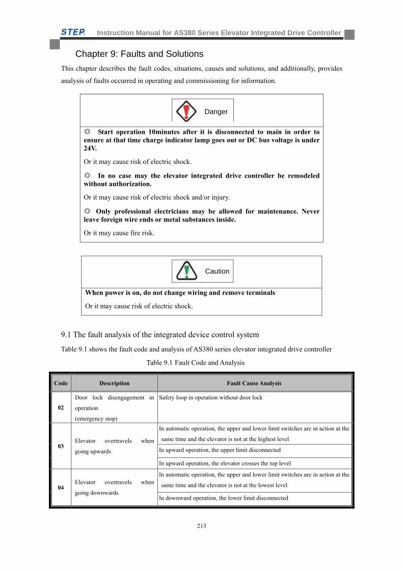
Instruction Manual for AS380 Series Elevator Integrated Drive Controller
213
Chapter 9: Faults and Solutions
This chapter describes the fault codes, situations, causes and solutions, and additionally, provides
analysis of faults occurred in operating and commissioning for information.
Start operation 10minutes after it is disconnected to main in order to ensure at that time charge indicator lamp goes out or DC bus voltage is under 24V.
Or it may cause risk of electric shock.
In no case may the elevator integrated drive controller be remodeled without authorization.
Or it may cause risk of electric shock and/or injury.
Only professional electricians may be allowed for maintenance. Never leave foreign wire ends or metal substances inside.
Or it may cause fire risk.
When power is on, do not change wiring and remove terminals
Or it may cause risk of electric shock.
9.1 The fault analysis of the integrated device control system
Table 9.1 shows the fault code and analysis of AS380 series elevator integrated drive controller
Table 9.1 Fault Code and Analysis
Code Description Fault Cause Analysis
02
Door lock disengagement in
operation
(emergency stop)
Safety loop in operation without door lock
03 Elevator overtravels when
going upwards
In automatic operation, the upper and lower limit switches are in action at the
same time and the elevator is not at the highest level
In upward operation, the upper limit disconnected
In upward operation, the elevator crosses the top level
04 Elevator overtravels when
going downwards
In automatic operation, the upper and lower limit switches are in action at the
same time and the elevator is not at the lowest level
In downward operation, the lower limit disconnected
Caution
Danger
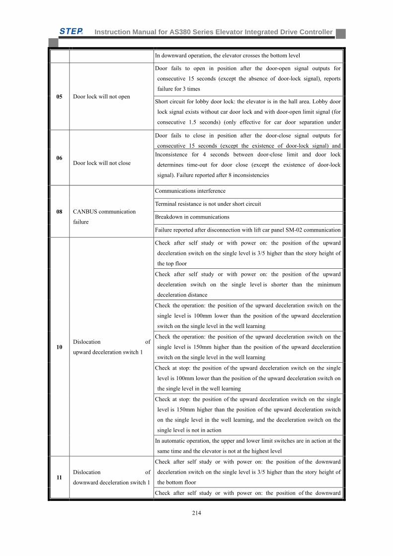
Instruction Manual for AS380 Series Elevator Integrated Drive Controller
214
In downward operation, the elevator crosses the bottom level
05 Door lock will not open
Door fails to open in position after the door-open signal outputs for
consecutive 15 seconds (except the absence of door-lock signal), reports
failure for 3 times
Short circuit for lobby door lock: the elevator is in the hall area. Lobby door
lock signal exists without car door lock and with door-open limit signal (for
consecutive 1.5 seconds) (only effective for car door separation under
06
Door lock will not close
Door fails to close in position after the door-close signal outputs for
consecutive 15 seconds (except the existence of door-lock signal) and
Inconsistence for 4 seconds between door-close limit and door lock
determines time-out for door close (except the existence of door-lock
signal). Failure reported after 8 inconsistencies
08
CANBUS communication
failure
Communications interference
Terminal resistance is not under short circuit
Breakdown in communications
Failure reported after disconnection with lift car panel SM-02 communication
10 Dislocation of
upward deceleration switch 1
Check after self study or with power on: the position of the upward
deceleration switch on the single level is 3/5 higher than the story height of
the top floor
Check after self study or with power on: the position of the upward
deceleration switch on the single level is shorter than the minimum
deceleration distance
Check the operation: the position of the upward deceleration switch on the
single level is 100mm lower than the position of the upward deceleration
switch on the single level in the well learning
Check the operation: the position of the upward deceleration switch on the
single level is 150mm higher than the position of the upward deceleration
switch on the single level in the well learning
Check at stop: the position of the upward deceleration switch on the single
level is 100mm lower than the position of the upward deceleration switch on
the single level in the well learning
Check at stop: the position of the upward deceleration switch on the single
level is 150mm higher than the position of the upward deceleration switch
on the single level in the well learning, and the deceleration switch on the
single level is not in action
In automatic operation, the upper and lower limit switches are in action at the
same time and the elevator is not at the highest level
11 Dislocation of
downward deceleration switch 1
Check after self study or with power on: the position of the downward
deceleration switch on the single level is 3/5 higher than the story height of
the bottom floor
Check after self study or with power on: the position of the downward
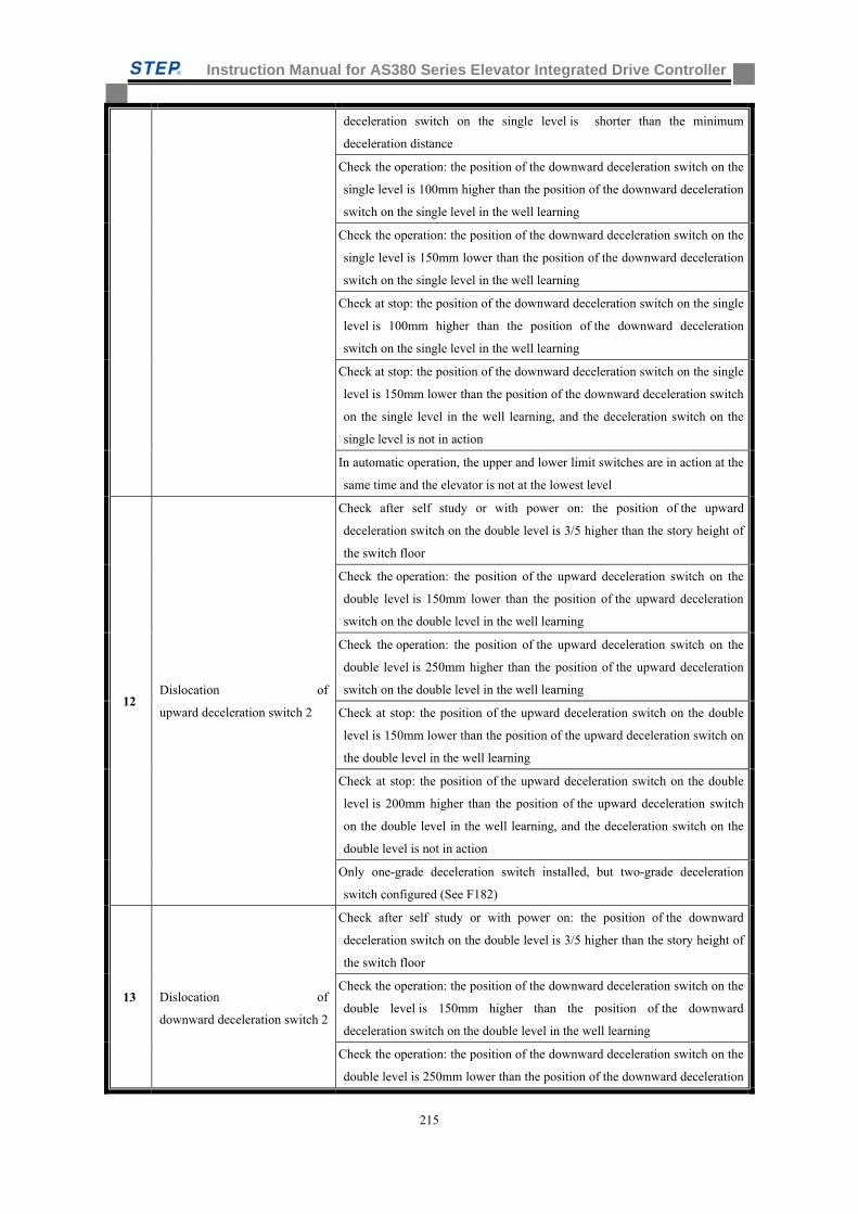
Instruction Manual for AS380 Series Elevator Integrated Drive Controller
215
deceleration switch on the single level is shorter than the minimum
deceleration distance
Check the operation: the position of the downward deceleration switch on the
single level is 100mm higher than the position of the downward deceleration
switch on the single level in the well learning
Check the operation: the position of the downward deceleration switch on the
single level is 150mm lower than the position of the downward deceleration
switch on the single level in the well learning
Check at stop: the position of the downward deceleration switch on the single
level is 100mm higher than the position of the downward deceleration
switch on the single level in the well learning
Check at stop: the position of the downward deceleration switch on the single
level is 150mm lower than the position of the downward deceleration switch
on the single level in the well learning, and the deceleration switch on the
single level is not in action
In automatic operation, the upper and lower limit switches are in action at the
same time and the elevator is not at the lowest level
12 Dislocation of
upward deceleration switch 2
Check after self study or with power on: the position of the upward
deceleration switch on the double level is 3/5 higher than the story height of
the switch floor
Check the operation: the position of the upward deceleration switch on the
double level is 150mm lower than the position of the upward deceleration
switch on the double level in the well learning
Check the operation: the position of the upward deceleration switch on the
double level is 250mm higher than the position of the upward deceleration
switch on the double level in the well learning
Check at stop: the position of the upward deceleration switch on the double
level is 150mm lower than the position of the upward deceleration switch on
the double level in the well learning
Check at stop: the position of the upward deceleration switch on the double
level is 200mm higher than the position of the upward deceleration switch
on the double level in the well learning, and the deceleration switch on the
double level is not in action
Only one-grade deceleration switch installed, but two-grade deceleration
switch configured (See F182)
13
Dislocation of
downward deceleration switch 2
Check after self study or with power on: the position of the downward
deceleration switch on the double level is 3/5 higher than the story height of
the switch floor
Check the operation: the position of the downward deceleration switch on the
double level is 150mm higher than the position of the downward
deceleration switch on the double level in the well learning
Check the operation: the position of the downward deceleration switch on the
double level is 250mm lower than the position of the downward deceleration
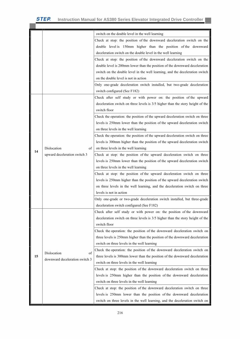
Instruction Manual for AS380 Series Elevator Integrated Drive Controller
216
switch on the double level in the well learning
Check at stop: the position of the downward deceleration switch on the
double level is 150mm higher than the position of the downward
deceleration switch on the double level in the well learning
Check at stop: the position of the downward deceleration switch on the
double level is 200mm lower than the position of the downward deceleration
switch on the double level in the well learning, and the deceleration switch
on the double level is not in action
Only one-grade deceleration switch installed, but two-grade deceleration
switch configured (See F182)
14 Dislocation of
upward deceleration switch 3
Check after self study or with power on: the position of the upward
deceleration switch on three levels is 3/5 higher than the story height of the
switch floor
Check the operation: the position of the upward deceleration switch on three
levels is 250mm lower than the position of the upward deceleration switch
on three levels in the well learning
Check the operation: the position of the upward deceleration switch on three
levels is 300mm higher than the position of the upward deceleration switch
on three levels in the well learning
Check at stop: the position of the upward deceleration switch on three
levels is 250mm lower than the position of the upward deceleration switch
on three levels in the well learning
Check at stop: the position of the upward deceleration switch on three
levels is 250mm higher than the position of the upward deceleration switch
on three levels in the well learning, and the deceleration switch on three
levels is not in action
Only one-grade or two-grade deceleration switch installed, but three-grade
deceleration switch configured (See F182)
15 Dislocation of
downward deceleration switch 3
Check after self study or with power on: the position of the downward
deceleration switch on three levels is 3/5 higher than the story height of the
switch floor
Check the operation: the position of the downward deceleration switch on
three levels is 250mm higher than the position of the downward deceleration
switch on three levels in the well learning
Check the operation: the position of the downward deceleration switch on
three levels is 300mm lower than the position of the downward deceleration
switch on three levels in the well learning
Check at stop: the position of the downward deceleration switch on three
levels is 250mm higher than the position of the downward deceleration
switch on three levels in the well learning
Check at stop: the position of the downward deceleration switch on three
levels is 250mm lower than the position of the downward deceleration
switch on three levels in the well learning, and the deceleration switch on
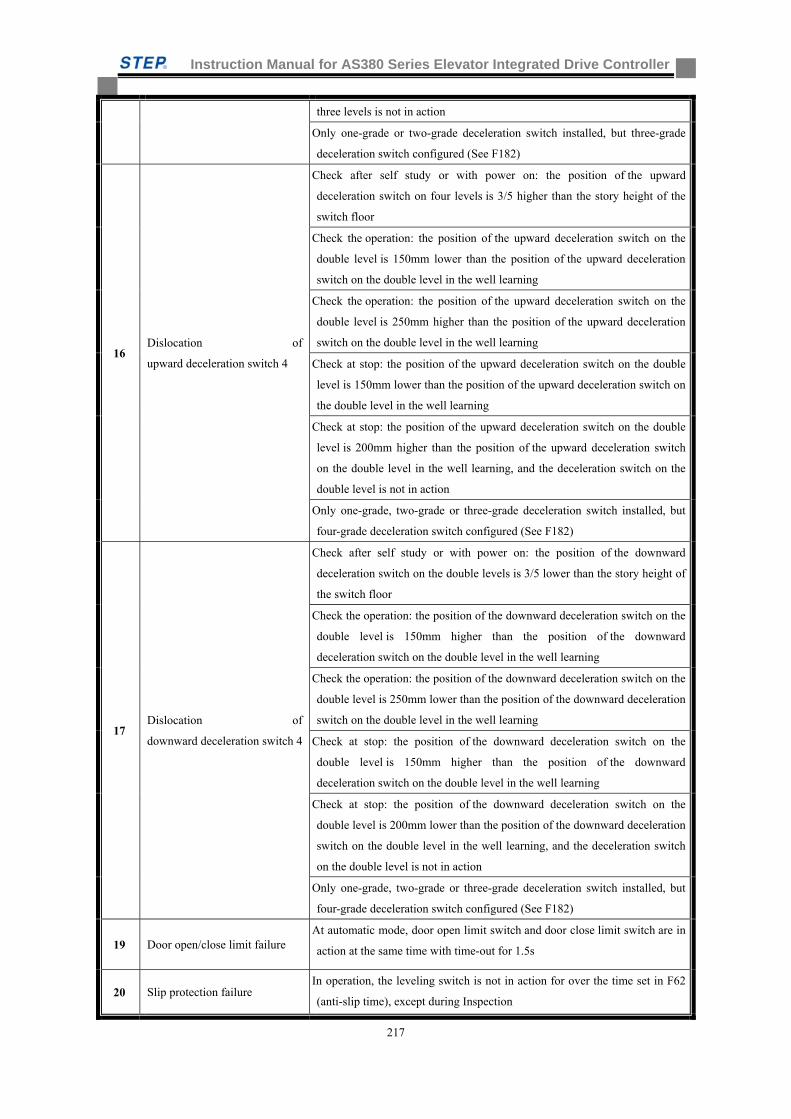
Instruction Manual for AS380 Series Elevator Integrated Drive Controller
217
three levels is not in action
Only one-grade or two-grade deceleration switch installed, but three-grade
deceleration switch configured (See F182)
16 Dislocation of
upward deceleration switch 4
Check after self study or with power on: the position of the upward
deceleration switch on four levels is 3/5 higher than the story height of the
switch floor
Check the operation: the position of the upward deceleration switch on the
double level is 150mm lower than the position of the upward deceleration
switch on the double level in the well learning
Check the operation: the position of the upward deceleration switch on the
double level is 250mm higher than the position of the upward deceleration
switch on the double level in the well learning
Check at stop: the position of the upward deceleration switch on the double
level is 150mm lower than the position of the upward deceleration switch on
the double level in the well learning
Check at stop: the position of the upward deceleration switch on the double
level is 200mm higher than the position of the upward deceleration switch
on the double level in the well learning, and the deceleration switch on the
double level is not in action
Only one-grade, two-grade or three-grade deceleration switch installed, but
four-grade deceleration switch configured (See F182)
17 Dislocation of
downward deceleration switch 4
Check after self study or with power on: the position of the downward
deceleration switch on the double levels is 3/5 lower than the story height of
the switch floor
Check the operation: the position of the downward deceleration switch on the
double level is 150mm higher than the position of the downward
deceleration switch on the double level in the well learning
Check the operation: the position of the downward deceleration switch on the
double level is 250mm lower than the position of the downward deceleration
switch on the double level in the well learning
Check at stop: the position of the downward deceleration switch on the
double level is 150mm higher than the position of the downward
deceleration switch on the double level in the well learning
Check at stop: the position of the downward deceleration switch on the
double level is 200mm lower than the position of the downward deceleration
switch on the double level in the well learning, and the deceleration switch
on the double level is not in action
Only one-grade, two-grade or three-grade deceleration switch installed, but
four-grade deceleration switch configured (See F182)
19 Door open/close limit failure At automatic mode, door open limit switch and door close limit switch are in
action at the same time with time-out for 1.5s
20 Slip protection failure In operation, the leveling switch is not in action for over the time set in F62
(anti-slip time), except during Inspection
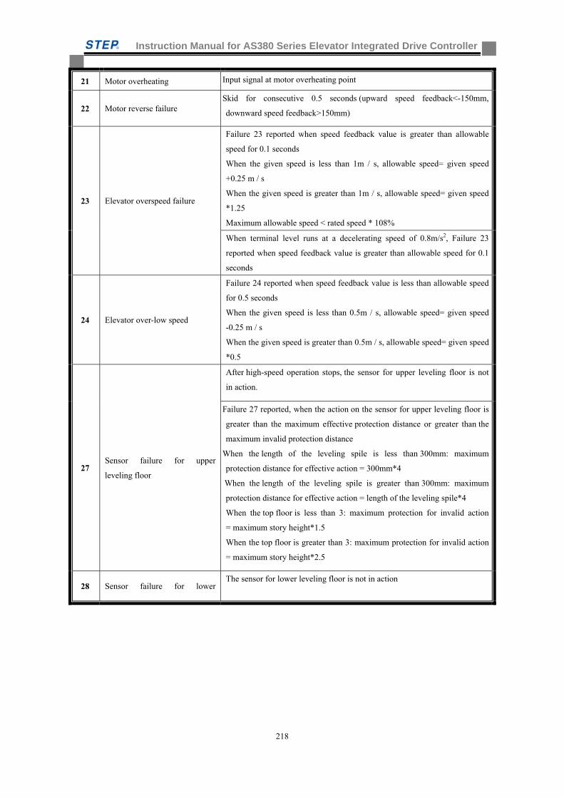
Instruction Manual for AS380 Series Elevator Integrated Drive Controller
218
21 Motor overheating Input signal at motor overheating point
22 Motor reverse failure Skid for consecutive 0.5 seconds (upward speed feedback<-150mm,
downward speed feedback>150mm)
23 Elevator overspeed failure
Failure 23 reported when speed feedback value is greater than allowable
speed for 0.1 seconds
When the given speed is less than 1m / s, allowable speed= given speed
+0.25 m / s
When the given speed is greater than 1m / s, allowable speed= given speed
*1.25
Maximum allowable speed < rated speed * 108%
When terminal level runs at a decelerating speed of 0.8m/s2, Failure 23
reported when speed feedback value is greater than allowable speed for 0.1
seconds
24 Elevator over-low speed
Failure 24 reported when speed feedback value is less than allowable speed
for 0.5 seconds
When the given speed is less than 0.5m / s, allowable speed= given speed
-0.25 m / s
When the given speed is greater than 0.5m / s, allowable speed= given speed
*0.5
27 Sensor failure for upper
leveling floor
After high-speed operation stops, the sensor for upper leveling floor is not
in action.
Failure 27 reported, when the action on the sensor for upper leveling floor is
greater than the maximum effective protection distance or greater than the
maximum invalid protection distance
When the length of the leveling spile is less than 300mm: maximum
protection distance for effective action = 300mm*4
When the length of the leveling spile is greater than 300mm: maximum
protection distance for effective action = length of the leveling spile*4
When the top floor is less than 3: maximum protection for invalid action
= maximum story height*1.5
When the top floor is greater than 3: maximum protection for invalid action
= maximum story height*2.5
28 Sensor failure for lower The sensor for lower leveling floor is not in action
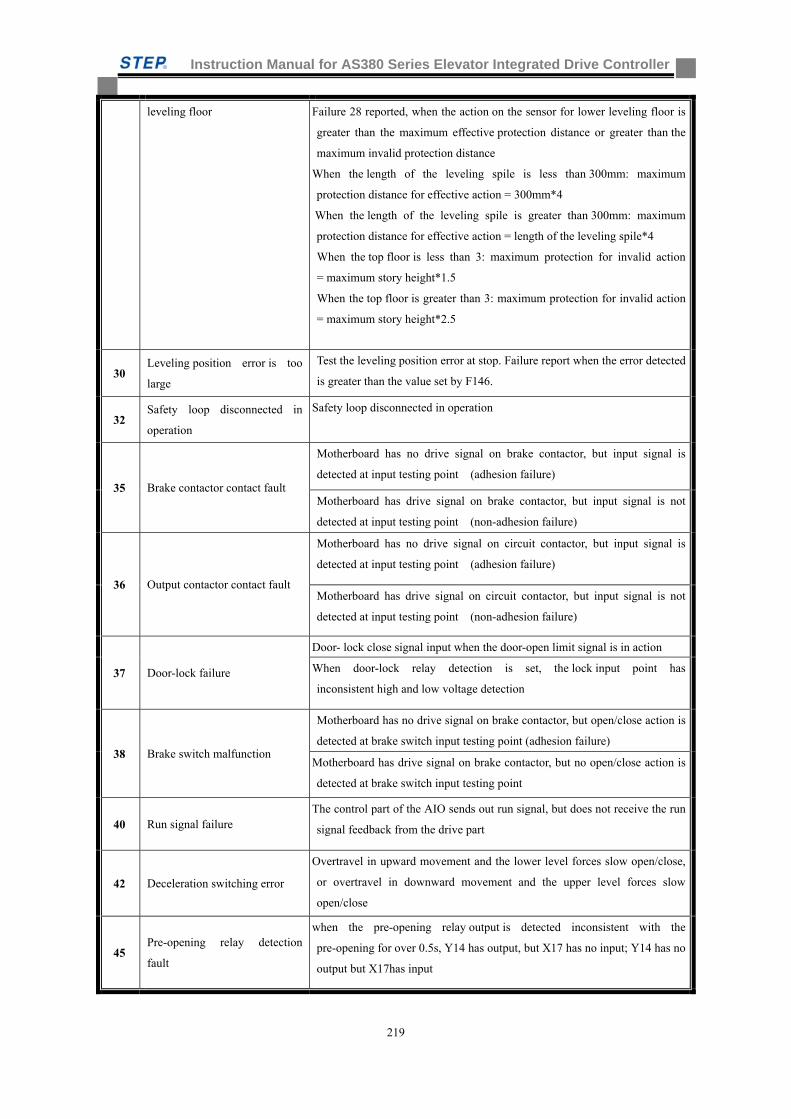
Instruction Manual for AS380 Series Elevator Integrated Drive Controller
219
leveling floor Failure 28 reported, when the action on the sensor for lower leveling floor is
greater than the maximum effective protection distance or greater than the
maximum invalid protection distance
When the length of the leveling spile is less than 300mm: maximum
protection distance for effective action = 300mm*4
When the length of the leveling spile is greater than 300mm: maximum
protection distance for effective action = length of the leveling spile*4
When the top floor is less than 3: maximum protection for invalid action
= maximum story height*1.5
When the top floor is greater than 3: maximum protection for invalid action
= maximum story height*2.5
30 Leveling position error is too
large
Test the leveling position error at stop. Failure report when the error detected
is greater than the value set by F146.
32 Safety loop disconnected in
operation
Safety loop disconnected in operation
35 Brake contactor contact fault
Motherboard has no drive signal on brake contactor, but input signal is
detected at input testing point (adhesion failure)
Motherboard has drive signal on brake contactor, but input signal is not
detected at input testing point (non-adhesion failure)
36 Output contactor contact fault
Motherboard has no drive signal on circuit contactor, but input signal is
detected at input testing point (adhesion failure)
Motherboard has drive signal on circuit contactor, but input signal is not
detected at input testing point (non-adhesion failure)
37 Door-lock failure
Door- lock close signal input when the door-open limit signal is in action
When door-lock relay detection is set, the lock input point has
inconsistent high and low voltage detection
38 Brake switch malfunction
Motherboard has no drive signal on brake contactor, but open/close action is
detected at brake switch input testing point (adhesion failure)
Motherboard has drive signal on brake contactor, but no open/close action is
detected at brake switch input testing point
40 Run signal failure The control part of the AIO sends out run signal, but does not receive the run
signal feedback from the drive part
42 Deceleration switching error
Overtravel in upward movement and the lower level forces slow open/close,
or overtravel in downward movement and the upper level forces slow
open/close
45 Pre-opening relay detection
fault
when the pre-opening relay output is detected inconsistent with the
pre-opening for over 0.5s, Y14 has output, but X17 has no input; Y14 has no
output but X17has input
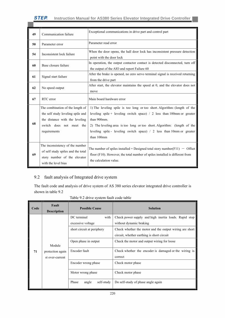
Instruction Manual for AS380 Series Elevator Integrated Drive Controller
220
49 Communication failure Exceptional communications in drive part and control part
50 Parameter error Parameter read error
54 Inconsistent lock failure When the door opens, the hall door lock has inconsistent pressure detection
point with the door lock
60 Base closure failure In operation, the output contactor contact is detected disconnected, turn off
the output of the AIO and report Failure 60
61 Signal start failure After the brake is opened, no zero servo terminal signal is received returning
from the drive part
62 No speed output After start, the elevator maintains the speed at 0, and the elevator does not
move
67 RTC error Main board hardware error
68
The combination of the length of
the self study leveling spile and
the distance with the leveling
switch does not meet the
requirements
1) The leveling spile is too long or too short. Algorithm: (length of the
leveling spile + leveling switch space) / 2 less than 100mm or greater
than 900mm.
2) The leveling area is too long or too short. Algorithm: (length of the
leveling spile - leveling switch space) / 2 less than 10mm or greater
than 100mm
69
The inconsistency of the number
of self study spiles and the total
story number of the elevator
with the level bias
The number of spiles installed = Designed total story number(F11) - Offset
floor (F10). However, the total number of spiles installed is different from
the calculation value.
9.2 fault analysis of Integrated drive system
The fault code and analysis of drive system of AS 380 series elevator integrated drive controller is
shown in table 9.2
Table 9.2 drive system fault code table
Code Fault
Description Possible Cause Solution
71
Module
protection again
st over-current
DC terminal with
excessive voltage
Check power supply and high inertia loads. Rapid stop
without dynamic braking
short circuit at periphery Check whether the motor and the output wiring are short
circuit, whether earthing is short circuit
Open phase in output Check the motor and output wiring for loose
Encoder fault Check whether the encoder is damaged or the wiring is
correct
Encoder wrong phase Check motor phase
Motor wrong phase Check motor phase
Phase angle self-study Do self-study of phase angle again
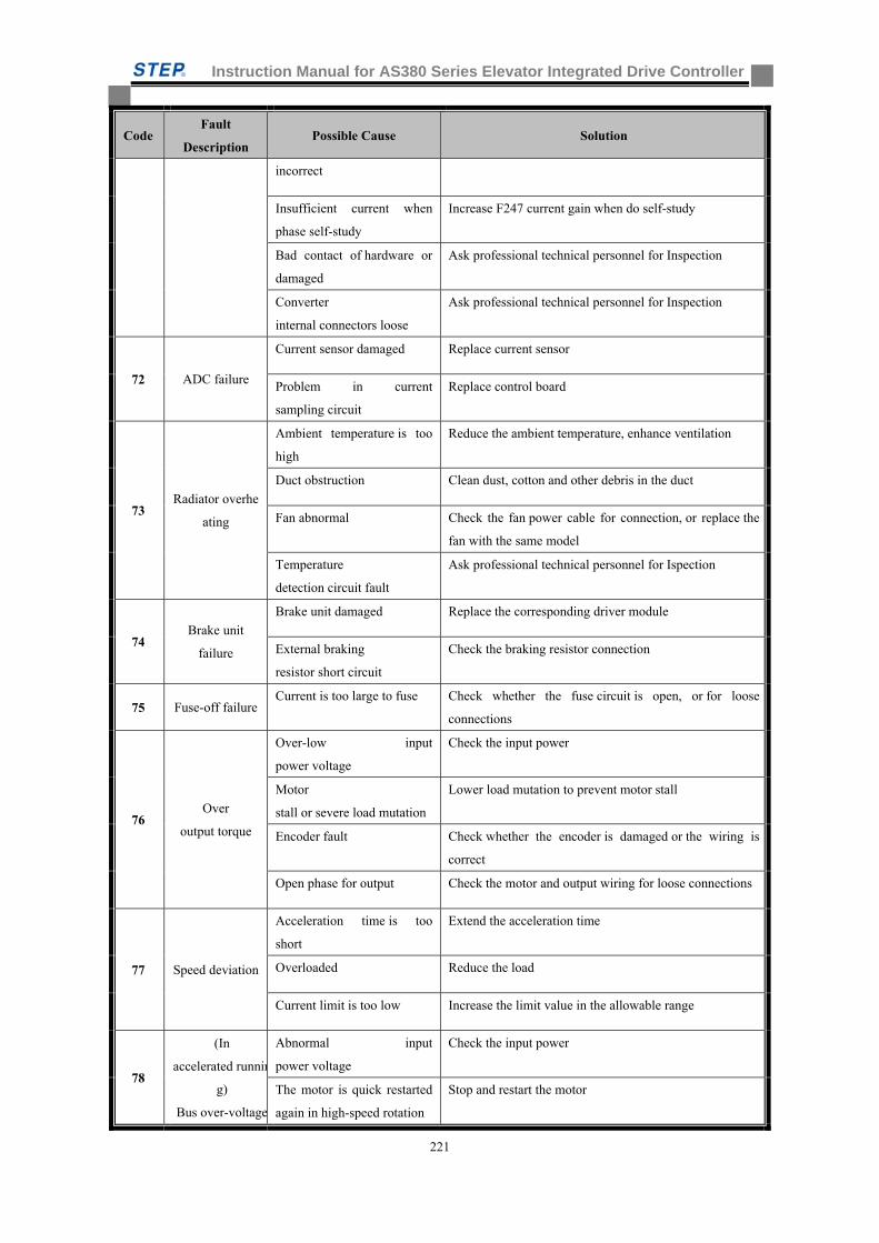
Instruction Manual for AS380 Series Elevator Integrated Drive Controller
221
Code Fault
Description Possible Cause Solution
incorrect
Insufficient current when
phase self-study
Increase F247 current gain when do self-study
Bad contact of hardware or
damaged
Ask professional technical personnel for Inspection
Converter
internal connectors loose
Ask professional technical personnel for Inspection
72 ADC failure
Current sensor damaged Replace current sensor
Problem in current
sampling circuit
Replace control board
73 Radiator overhe
ating
Ambient temperature is too
high
Reduce the ambient temperature, enhance ventilation
Duct obstruction Clean dust, cotton and other debris in the duct
Fan abnormal Check the fan power cable for connection, or replace the
fan with the same model
Temperature
detection circuit fault
Ask professional technical personnel for Ispection
74 Brake unit
failure
Brake unit damaged Replace the corresponding driver module
External braking
resistor short circuit
Check the braking resistor connection
75 Fuse-off failure Current is too large to fuse Check whether the fuse circuit is open, or for loose
connections
76 Over
output torque
Over-low input
power voltage
Check the input power
Motor
stall or severe load mutation
Lower load mutation to prevent motor stall
Encoder fault Check whether the encoder is damaged or the wiring is
correct
Open phase for output Check the motor and output wiring for loose connections
77 Speed deviation
Acceleration time is too
short
Extend the acceleration time
Overloaded Reduce the load
Current limit is too low Increase the limit value in the allowable range
78
(In
accelerated runnin
g)
Bus over-voltage
Abnormal input
power voltage
Check the input power
The motor is quick restarted
again in high-speed rotation
Stop and restart the motor
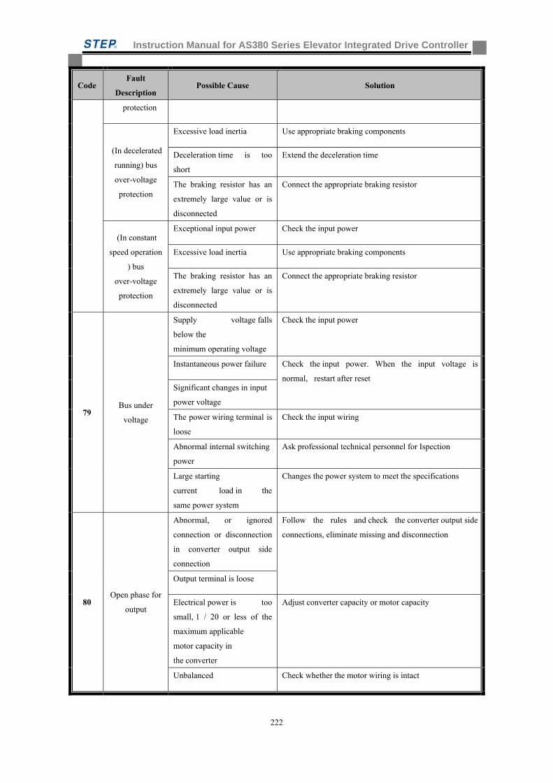
Instruction Manual for AS380 Series Elevator Integrated Drive Controller
222
Code Fault
Description Possible Cause Solution
protection
(In decelerated
running) bus
over-voltage
protection
Excessive load inertia Use appropriate braking components
Deceleration time is too
short
Extend the deceleration time
The braking resistor has an
extremely large value or is
disconnected
Connect the appropriate braking resistor
(In constant
speed operation
) bus
over-voltage
protection
Exceptional input power Check the input power
Excessive load inertia Use appropriate braking components
The braking resistor has an
extremely large value or is
disconnected
Connect the appropriate braking resistor
79 Bus under
voltage
Supply voltage falls
below the
minimum operating voltage
Check the input power
Instantaneous power failure Check the input power. When the input voltage is
normal, restart after reset Significant changes in input
power voltage
The power wiring terminal is
loose
Check the input wiring
Abnormal internal switching
power
Ask professional technical personnel for Ispection
Large starting
current load in the
same power system
Changes the power system to meet the specifications
80 Open phase for
output
Abnormal, or ignored
connection or disconnection
in converter output side
connection
Follow the rules and check the converter output side
connections, eliminate missing and disconnection
Output terminal is loose
Electrical power is too
small, 1 / 20 or less of the
maximum applicable
motor capacity in
the converter
Adjust converter capacity or motor capacity
Unbalanced Check whether the motor wiring is intact
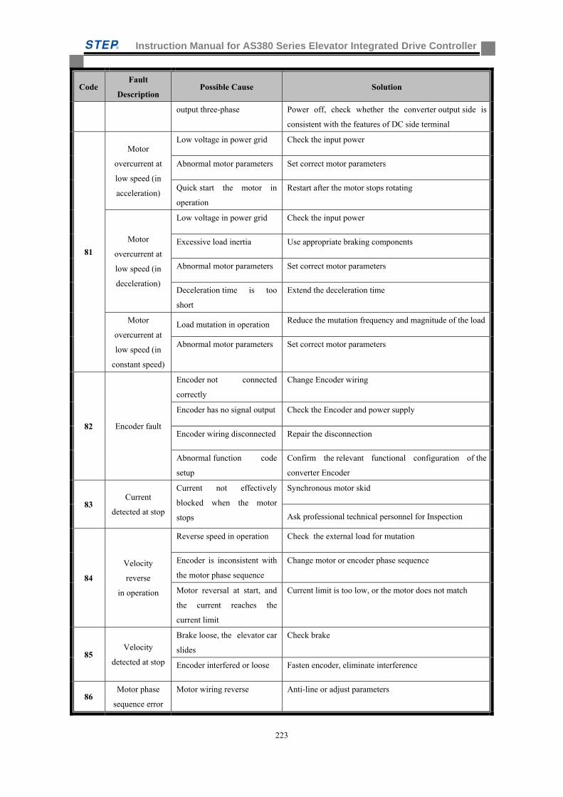
Instruction Manual for AS380 Series Elevator Integrated Drive Controller
223
Code Fault
Description Possible Cause Solution
output three-phase Power off, check whether the converter output side is
consistent with the features of DC side terminal
81
Motor
overcurrent at
low speed (in
acceleration)
Low voltage in power grid Check the input power
Abnormal motor parameters Set correct motor parameters
Quick start the motor in
operation
Restart after the motor stops rotating
Motor
overcurrent at
low speed (in
deceleration)
Low voltage in power grid Check the input power
Excessive load inertia Use appropriate braking components
Abnormal motor parameters Set correct motor parameters
Deceleration time is too
short
Extend the deceleration time
Motor
overcurrent at
low speed (in
constant speed)
Load mutation in operation Reduce the mutation frequency and magnitude of the load
Abnormal motor parameters Set correct motor parameters
82 Encoder fault
Encoder not connected
correctly
Change Encoder wiring
Encoder has no signal output Check the Encoder and power supply
Encoder wiring disconnected Repair the disconnection
Abnormal function code
setup
Confirm the relevant functional configuration of the
converter Encoder
83 Current
detected at stop
Current not effectively
blocked when the motor
stops
Synchronous motor skid
Ask professional technical personnel for Inspection
84
Velocity
reverse
in operation
Reverse speed in operation Check the external load for mutation
Encoder is inconsistent with
the motor phase sequence
Change motor or encoder phase sequence
Motor reversal at start, and
the current reaches the
current limit
Current limit is too low, or the motor does not match
85 Velocity
detected at stop
Brake loose, the elevator car
slides
Check brake
Encoder interfered or loose Fasten encoder, eliminate interference
86 Motor phase
sequence error
Motor wiring reverse Anti-line or adjust parameters
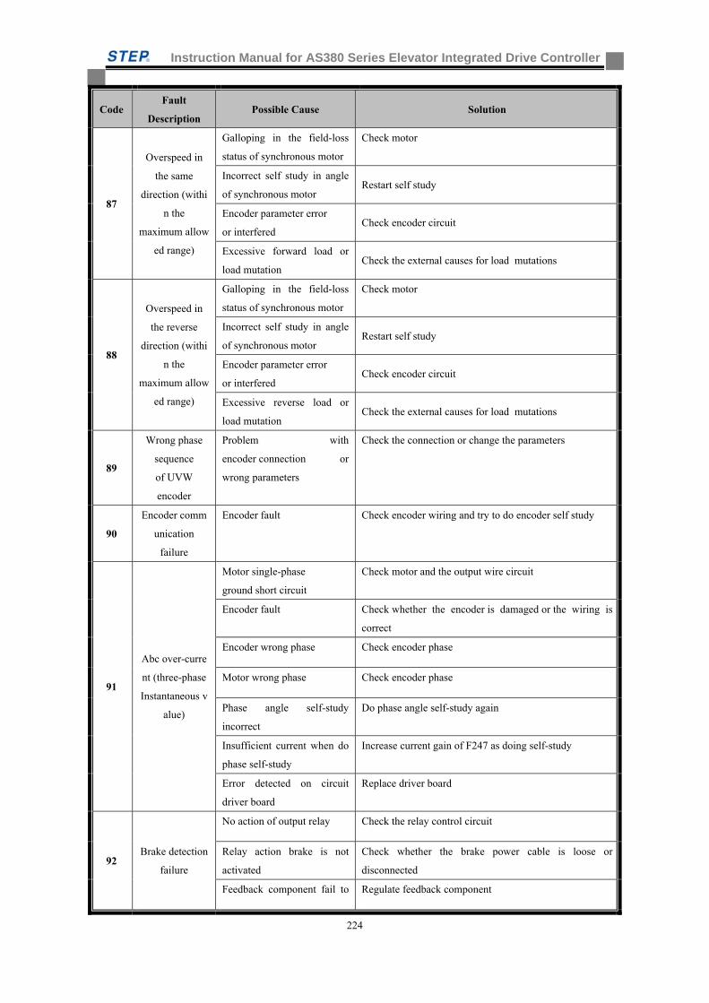
Instruction Manual for AS380 Series Elevator Integrated Drive Controller
224
Code Fault
Description Possible Cause Solution
87
Overspeed in
the same
direction (withi
n the
maximum allow
ed range)
Galloping in the field-loss
status of synchronous motor
Check motor
Incorrect self study in angle
of synchronous motor Restart self study
Encoder parameter error
or interfered Check encoder circuit
Excessive forward load or
load mutation Check the external causes for load mutations
88
Overspeed in
the reverse
direction (withi
n the
maximum allow
ed range)
Galloping in the field-loss
status of synchronous motor
Check motor
Incorrect self study in angle
of synchronous motor Restart self study
Encoder parameter error
or interfered Check encoder circuit
Excessive reverse load or
load mutation Check the external causes for load mutations
89
Wrong phase
sequence
of UVW
encoder
Problem with
encoder connection or
wrong parameters
Check the connection or change the parameters
90
Encoder comm
unication
failure
Encoder fault Check encoder wiring and try to do encoder self study
91
Abc over-curre
nt (three-phase
Instantaneous v
alue)
Motor single-phase
ground short circuit
Check motor and the output wire circuit
Encoder fault Check whether the encoder is damaged or the wiring is
correct
Encoder wrong phase Check encoder phase
Motor wrong phase Check encoder phase
Phase angle self-study
incorrect
Do phase angle self-study again
Insufficient current when do
phase self-study
Increase current gain of F247 as doing self-study
Error detected on circuit
driver board
Replace driver board
92 Brake detection
failure
No action of output relay Check the relay control circuit
Relay action brake is not
activated
Check whether the brake power cable is loose or
disconnected
Feedback component fail to Regulate feedback component
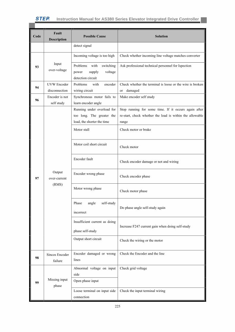
Instruction Manual for AS380 Series Elevator Integrated Drive Controller
225
Code Fault
Description Possible Cause Solution
detect signal
93 Input
over-voltage
Incoming voltage is too high Check whether incoming line voltage matches converter
Problems with switching
power supply voltage
detection circuit
Ask professional technical personnel for Ispection
94 UVW Encoder
disconnection
Problems with encoder
wiring circuit
Check whether the terminal is loose or the wire is broken
or damaged
96 Encoder is not
self study
Synchronous motor fails to
learn encoder angle
Make encoder self study
97
Output
over-current
(RMS)
Running under overload for
too long. The greater the
load, the shorter the time
Stop running for some time. If it occurs again after
re-start, check whether the load is within the allowable
range
Motor stall Check motor or brake
Motor coil short circuit Check motor
Encoder fault Check encoder damage or not and wiring
Encoder wrong phase Check encoder phase
Motor wrong phase Check motor phase
Phase angle self-study
incorrect Do phase angle self-study again
Insufficient current as doing
phase self-study Increase F247 current gain when doing self-study
Output short circuit Check the wiring or the motor
98 Sincos Encoder
failure
Encoder damaged or wrong
lines
Check the Encoder and the line
99 Missing input
phase
Abnormal voltage on input
side
Check grid voltage
Open phase input
Loose terminal on input side
connection
Check the input terminal wiring
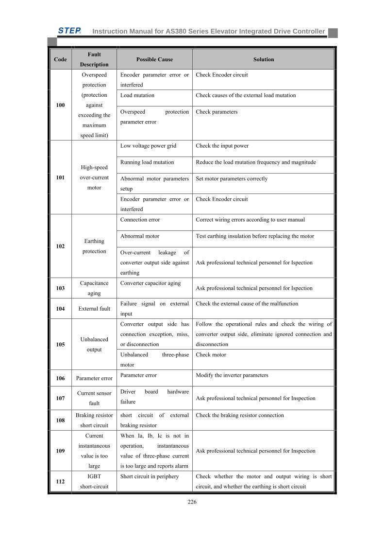
Instruction Manual for AS380 Series Elevator Integrated Drive Controller
226
Code Fault
Description Possible Cause Solution
100
Overspeed
protection
(protection
against
exceeding the
maximum
speed limit)
Encoder parameter error or
interfered
Check Encoder circuit
Load mutation Check causes of the external load mutation
Overspeed protection
parameter error
Check parameters
101
High-speed
over-current
motor
Low voltage power grid Check the input power
Running load mutation Reduce the load mutation frequency and magnitude
Abnormal motor parameters
setup
Set motor parameters correctly
Encoder parameter error or
interfered
Check Encoder circuit
102 Earthing
protection
Connection error Correct wiring errors according to user manual
Abnormal motor Test earthing insulation before replacing the motor
Over-current leakage of
converter output side against
earthing
Ask professional technical personnel for Ispection
103 Capacitance
aging
Converter capacitor aging Ask professional technical personnel for Ispection
104 External fault Failure signal on external
input
Check the external cause of the malfunction
105 Unbalanced
output
Converter output side has
connection exception, miss,
or disconnection
Follow the operational rules and check the wiring of
converter output side, eliminate ignored connection and
disconnection
Unbalanced three-phase
motor
Check motor
106 Parameter error Parameter error Modify the inverter parameters
107 Current sensor
fault
Driver board hardware
failure Ask professional technical personnel for Inspection
108 Braking resistor
short circuit
short circuit of external
braking resistor
Check the braking resistor connection
109
Current
instantaneous
value is too
large
When Ia, Ib, Ic is not in
operation, instantaneous
value of three-phase current
is too large and reports alarm
Ask professional technical personnel for Inspection
112 IGBT
short-circuit
Short circuit in periphery Check whether the motor and output wiring is short
circuit, and whether the earthing is short circuit
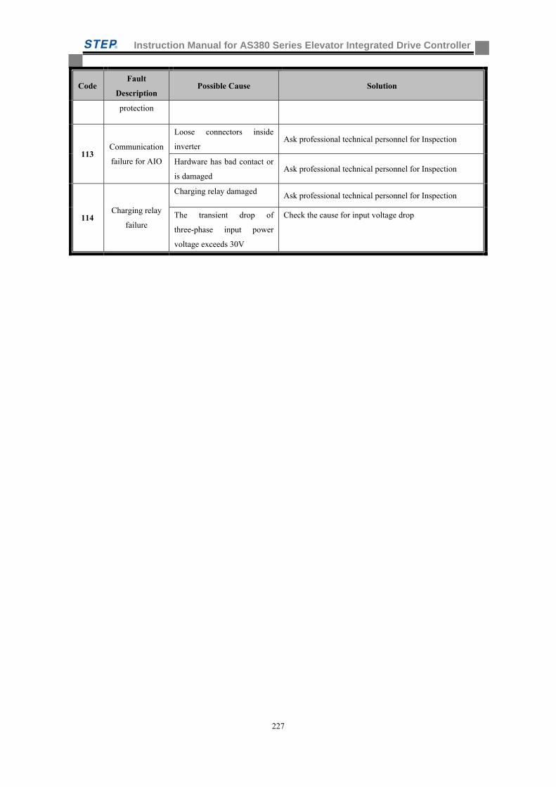
Instruction Manual for AS380 Series Elevator Integrated Drive Controller
227
Code Fault
Description Possible Cause Solution
protection
113 Communication
failure for AIO
Loose connectors inside
inverter Ask professional technical personnel for Inspection
Hardware has bad contact or
is damaged Ask professional technical personnel for Inspection
114 Charging relay
failure
Charging relay damaged Ask professional technical personnel for Inspection
The transient drop of
three-phase input power
voltage exceeds 30V
Check the cause for input voltage drop
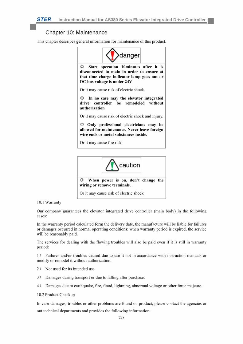
Instruction Manual for AS380 Series Elevator Integrated Drive Controller
228
Chapter 10: Maintenance
This chapter describes general information for maintenance of this product.
Start operation 10minutes after it is disconnected to main in order to ensure at that time charge indicator lamp goes out or DC bus voltage is under 24V
Or it may cause risk of electric shock.
In no case may the elevator integrated drive controller be remodeled without authorization
Or it may cause risk of electric shock and injury.
Only professional electricians may be allowed for maintenance. Never leave foreign wire ends or metal substances inside.
Or it may cause fire risk.
When power is on, don’t change the wiring or remove terminals.
Or it may cause risk of electric shock
10.1 Warranty
Our company guarantees the elevator integrated drive controller (main body) in the following cases:
In the warranty period calculated form the delivery date, the manufacture will be liable for failures or damages occurred in normal operating conditions; when warranty period is expired, the service will be reasonably paid.
The services for dealing with the flowing troubles will also be paid even if it is still in warranty period:
1) Failures and/or troubles caused due to use it not in accordance with instruction manuals or modify or remodel it without authorization.
2) Not used for its intended use.
3) Damages during transport or due to falling after purchase.
4) Damages due to earthquake, fire, flood, lightning, abnormal voltage or other force majeure.
10.2 Product Checkup
In case damages, troubles or other problems are found on product, please contact the agencies or
out technical departments and provides the following information:
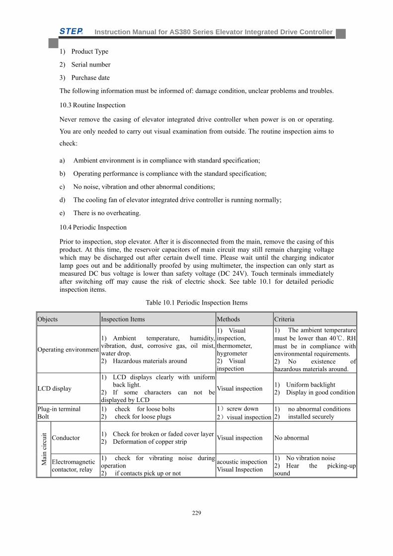
Instruction Manual for AS380 Series Elevator Integrated Drive Controller
229
1) Product Type
2) Serial number
3) Purchase date
The following information must be informed of: damage condition, unclear problems and troubles.
10.3 Routine Inspection
Never remove the casing of elevator integrated drive controller when power is on or operating.
You are only needed to carry out visual examination from outside. The routine inspection aims to
check:
a) Ambient environment is in compliance with standard specification;
b) Operating performance is compliance with the standard specification;
c) No noise, vibration and other abnormal conditions;
d) The cooling fan of elevator integrated drive controller is running normally;
e) There is no overheating.
10.4 Periodic Inspection
Prior to inspection, stop elevator. After it is disconnected from the main, remove the casing of this product. At this time, the reservoir capacitors of main circuit may still remain charging voltage which may be discharged out after certain dwell time. Please wait until the charging indicator lamp goes out and be additionally proofed by using multimeter, the inspection can only start as measured DC bus voltage is lower than safety voltage (DC 24V). Touch terminals immediately after switching off may cause the risk of electric shock. See table 10.1 for detailed periodic inspection items.
Table 10.1 Periodic Inspection Items
Objects Inspection Items Methods Criteria
Operating environment
1) Ambient temperature, humidity, vibration, dust, corrosive gas, oil mist, water drop. 2) Hazardous materials around
1) Visual inspection, thermometer, hygrometer 2) Visual inspection
1) The ambient temperature must be lower than 40. RH must be in compliance with environmental requirements. 2) No existence of hazardous materials around.
LCD display
1) LCD displays clearly with uniform back light.
2) If some characters can not be displayed by LCD
Visual inspection 1) Uniform backlight 2) Display in good condition
Plug-in terminal Bolt
1) check for loose bolts 2) check for loose plugs
1)screw down 2)visual inspection
1) no abnormal conditions2) installed securely
Mai
n ci
rcui
t
Conductor 1) Check for broken or faded cover layer 2) Deformation of copper strip
Visual inspection No abnormal
Electromagnetic contactor, relay
1) check for vibrating noise during operation 2) if contacts pick up or not
acoustic inspectionVisual Inspection
1) No vibration noise 2) Hear the picking-up sound
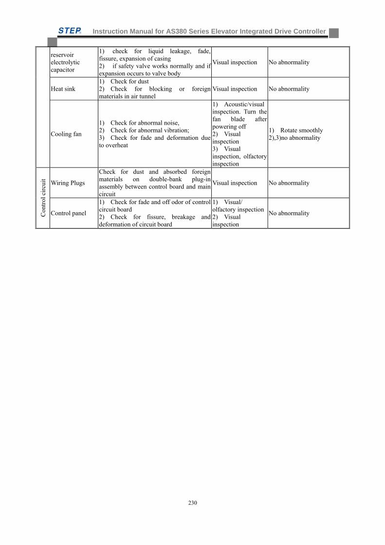
Instruction Manual for AS380 Series Elevator Integrated Drive Controller
230
reservoir electrolytic capacitor
1) check for liquid leakage, fade, fissure, expansion of casing 2) if safety valve works normally and if expansion occurs to valve body
Visual inspection No abnormality
Heat sink 1) Check for dust 2) Check for blocking or foreignmaterials in air tunnel
Visual inspection No abnormality
Cooling fan
1) Check for abnormal noise, 2) Check for abnormal vibration; 3) Check for fade and deformation due to overheat
1) Acoustic/visual inspection. Turn the fan blade after powering off 2) Visual inspection 3) Visual inspection, olfactory inspection
1) Rotate smoothly 2),3)no abnormality
Con
trol
cir
cuit Wiring Plugs
Check for dust and absorbed foreign materials on double-bank plug-in assembly between control board and main circuit
Visual inspection No abnormality
Control panel
1) Check for fade and off odor of control circuit board 2) Check for fissure, breakage and deformation of circuit board
1) Visual/ olfactory inspection2) Visual inspection
No abnormality
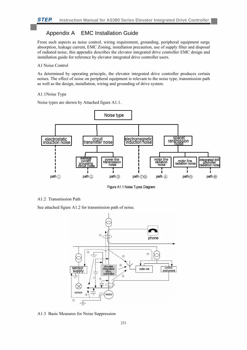
Instruction Manual for AS380 Series Elevator Integrated Drive Controller
231
Appendix A EMC Installation Guide
From such aspects as noise control, wiring requirement, grounding, peripheral equipment surge absorption, leakage current, EMC Zoning, installation precaution, use of supply filter and disposal of radiated noise, this appendix describes the elevator integrated drive controller EMC design and installation guide for reference by elevator integrated drive controller users.
A1 Noise Control
As determined by operating principle, the elevator integrated drive controller produces certain noises. The effect of noise on peripheral equipment is relevant to the noise type, transmission path as well as the design, installation, wiring and grounding of drive system.
A1.1 Noise Type
Noise types are shown by Attached figure A1.1.
A1.2 Transmission Path
See attached figure A1.2 for transmission path of noise.
A1.3 Basic Measures for Noise Suppression
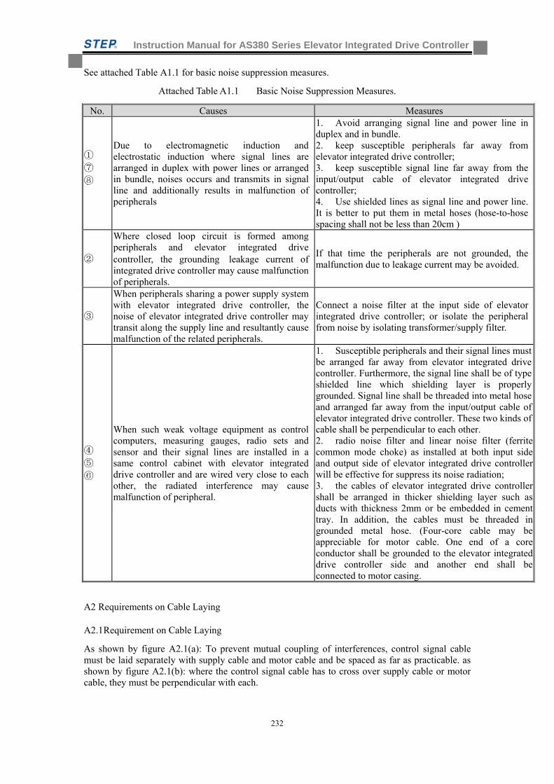
Instruction Manual for AS380 Series Elevator Integrated Drive Controller
232
See attached Table A1.1 for basic noise suppression measures.
Attached Table A1.1 Basic Noise Suppression Measures.
No. Causes Measures
① ⑦ ⑧
Due to electromagnetic induction and electrostatic induction where signal lines are arranged in duplex with power lines or arranged in bundle, noises occurs and transmits in signal line and additionally results in malfunction of peripherals
1. Avoid arranging signal line and power line in duplex and in bundle. 2. keep susceptible peripherals far away from elevator integrated drive controller; 3. keep susceptible signal line far away from the input/output cable of elevator integrated drive controller; 4. Use shielded lines as signal line and power line. It is better to put them in metal hoses (hose-to-hose spacing shall not be less than 20cm )
②
Where closed loop circuit is formed among peripherals and elevator integrated drive controller, the grounding leakage current of integrated drive controller may cause malfunction of peripherals.
If that time the peripherals are not grounded, the malfunction due to leakage current may be avoided.
③
When peripherals sharing a power supply system with elevator integrated drive controller, the noise of elevator integrated drive controller may transit along the supply line and resultantly cause malfunction of the related peripherals.
Connect a noise filter at the input side of elevator integrated drive controller; or isolate the peripheral from noise by isolating transformer/supply filter.
④ ⑤ ⑥
When such weak voltage equipment as control computers, measuring gauges, radio sets and sensor and their signal lines are installed in a same control cabinet with elevator integrated drive controller and are wired very close to each other, the radiated interference may cause malfunction of peripheral.
1. Susceptible peripherals and their signal lines must be arranged far away from elevator integrated drive controller. Furthermore, the signal line shall be of type shielded line which shielding layer is properly grounded. Signal line shall be threaded into metal hose and arranged far away from the input/output cable of elevator integrated drive controller. These two kinds of cable shall be perpendicular to each other. 2. radio noise filter and linear noise filter (ferrite common mode choke) as installed at both input side and output side of elevator integrated drive controller will be effective for suppress its noise radiation; 3. the cables of elevator integrated drive controller shall be arranged in thicker shielding layer such as ducts with thickness 2mm or be embedded in cement tray. In addition, the cables must be threaded in grounded metal hose. (Four-core cable may be appreciable for motor cable. One end of a core conductor shall be grounded to the elevator integrated drive controller side and another end shall be connected to motor casing.
A2 Requirements on Cable Laying
A2.1 Requirement on Cable Laying
As shown by figure A2.1(a): To prevent mutual coupling of interferences, control signal cable must be laid separately with supply cable and motor cable and be spaced as far as practicable. as shown by figure A2.1(b): where the control signal cable has to cross over supply cable or motor cable, they must be perpendicular with each.
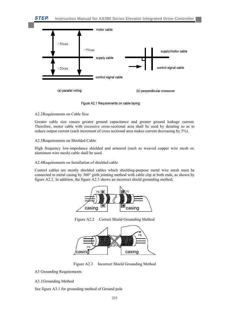
Instruction Manual for AS380 Series Elevator Integrated Drive Controller
233
A2.2 Requirements on Cable Size
Greater cable size causes greater ground capacitance and greater ground leakage current. Therefore, motor cable with excessive cross-sectional area shall be used by derating so as to reduce output current (each increment of cross sectional area makes current decreasing by 5%).
A2.3 Requirements on Shielded Cable
High frequency low-impedance shielded and armored (such as weaved copper wire mesh or, aluminum wire mesh) cable shall be used.
A2.4 Requirements on Installation of shielded cable
Control cables are mostly shielded cables which shielding-purpose metal wire mesh must be connected to metal casing by 360° girth jointing method with cable clip at both ends, as shown by figure A2.2. In addition, the figure A2.3 shows an incorrect shield grounding method.
Figure A2.2 Correct Shield Grounding Method
Figure A2.3 Incorrect Shield Grounding Method
A3 Grounding Requirements
A3.1 Grounding Method
See figure A3.1 for grounding method of Ground pole
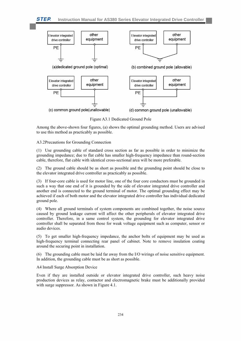
Instruction Manual for AS380 Series Elevator Integrated Drive Controller
234
Figure A3.1 Dedicated Ground Pole
Among the above-shown four figures, (a) shows the optimal grounding method. Users are advised to use this method as practicably as possible.
A3.2 Precautions for Grounding Connection
(1) Use grounding cable of standard cross section as far as possible in order to minimize the grounding impedance; due to flat cable has smaller high-frequency impedance than round-section cable, therefore, flat cable with identical cross-sectional area will be more preferable.
(2) The ground cable should be as short as possible and the grounding point should be close to the elevator integrated drive controller as practicably as possible.
(3) If four-core cable is used for motor line, one of the four core conductors must be grounded in such a way that one end of it is grounded by the side of elevator integrated drive controller and another end is connected to the ground terminal of motor. The optimal grounding effect may be achieved if each of both motor and the elevator integrated drive controller has individual dedicated ground pole.
(4) Where all ground terminals of system components are combined together, the noise source caused by ground leakage current will affect the other peripherals of elevator integrated drive controller. Therefore, in a same control system, the grounding for elevator integrated drive controller shall be separated from those for weak voltage equipment such as computer, sensor or audio devices.
(5) To get smaller high-frequency impedance, the anchor bolts of equipment may be used as high-frequency terminal connecting rear panel of cabinet. Note to remove insulation coating around the securing point in installation.
(6) The grounding cable must be laid far away from the I/O wirings of noise sensitive equipment. In addition, the grounding cable must be as short as possible.
A4 Install Surge Absorption Device
Even if they are installed outside or elevator integrated drive controller, such heavy noise production devices as relay, contactor and electromagnetic brake must be additionally provided with surge suppressor. As shown in Figure 4.1.
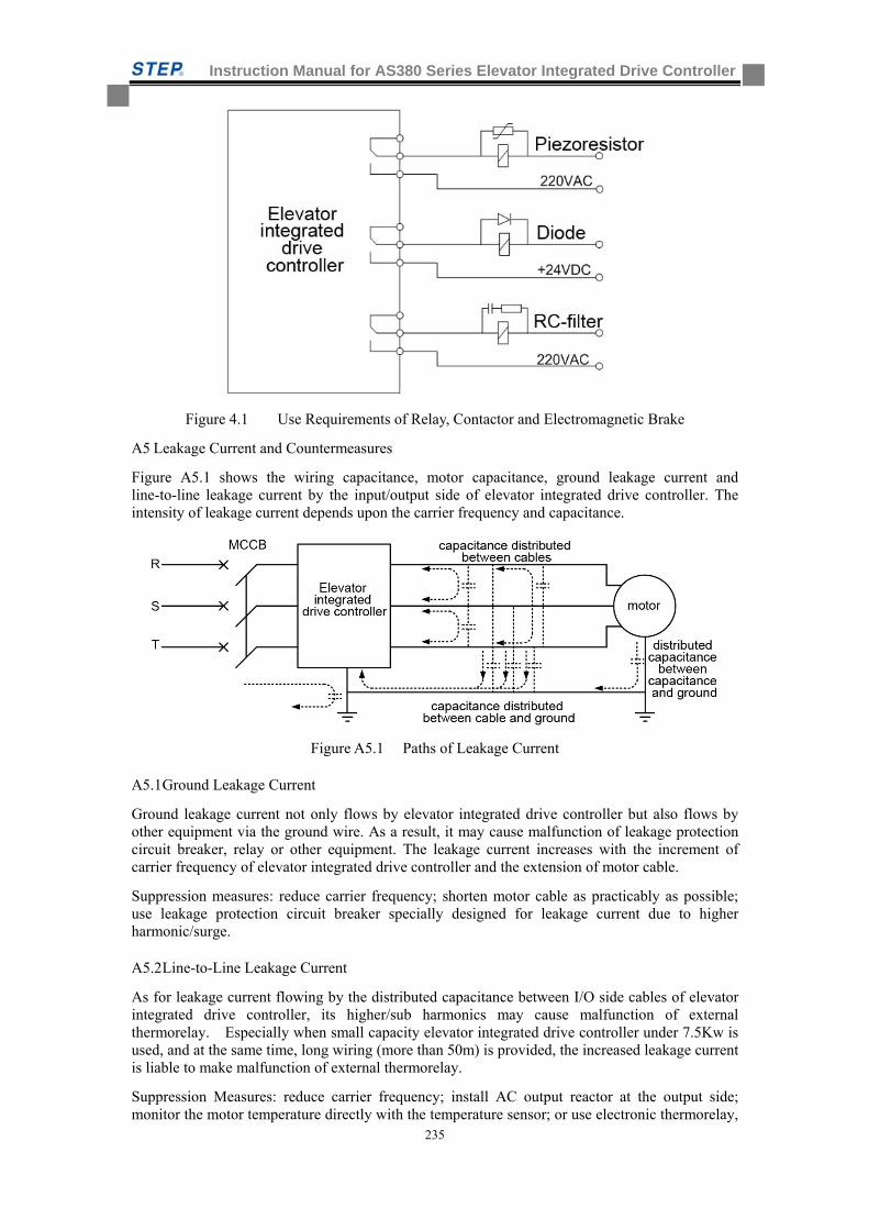
Instruction Manual for AS380 Series Elevator Integrated Drive Controller
235
Figure 4.1 Use Requirements of Relay, Contactor and Electromagnetic Brake
A5 Leakage Current and Countermeasures
Figure A5.1 shows the wiring capacitance, motor capacitance, ground leakage current and line-to-line leakage current by the input/output side of elevator integrated drive controller. The intensity of leakage current depends upon the carrier frequency and capacitance.
Figure A5.1 Paths of Leakage Current
A5.1 Ground Leakage Current
Ground leakage current not only flows by elevator integrated drive controller but also flows by other equipment via the ground wire. As a result, it may cause malfunction of leakage protection circuit breaker, relay or other equipment. The leakage current increases with the increment of carrier frequency of elevator integrated drive controller and the extension of motor cable.
Suppression measures: reduce carrier frequency; shorten motor cable as practicably as possible; use leakage protection circuit breaker specially designed for leakage current due to higher harmonic/surge.
A5.2 Line-to-Line Leakage Current
As for leakage current flowing by the distributed capacitance between I/O side cables of elevator integrated drive controller, its higher/sub harmonics may cause malfunction of external thermorelay. Especially when small capacity elevator integrated drive controller under 7.5Kw is used, and at the same time, long wiring (more than 50m) is provided, the increased leakage current is liable to make malfunction of external thermorelay.
Suppression Measures: reduce carrier frequency; install AC output reactor at the output side; monitor the motor temperature directly with the temperature sensor; or use electronic thermorelay,
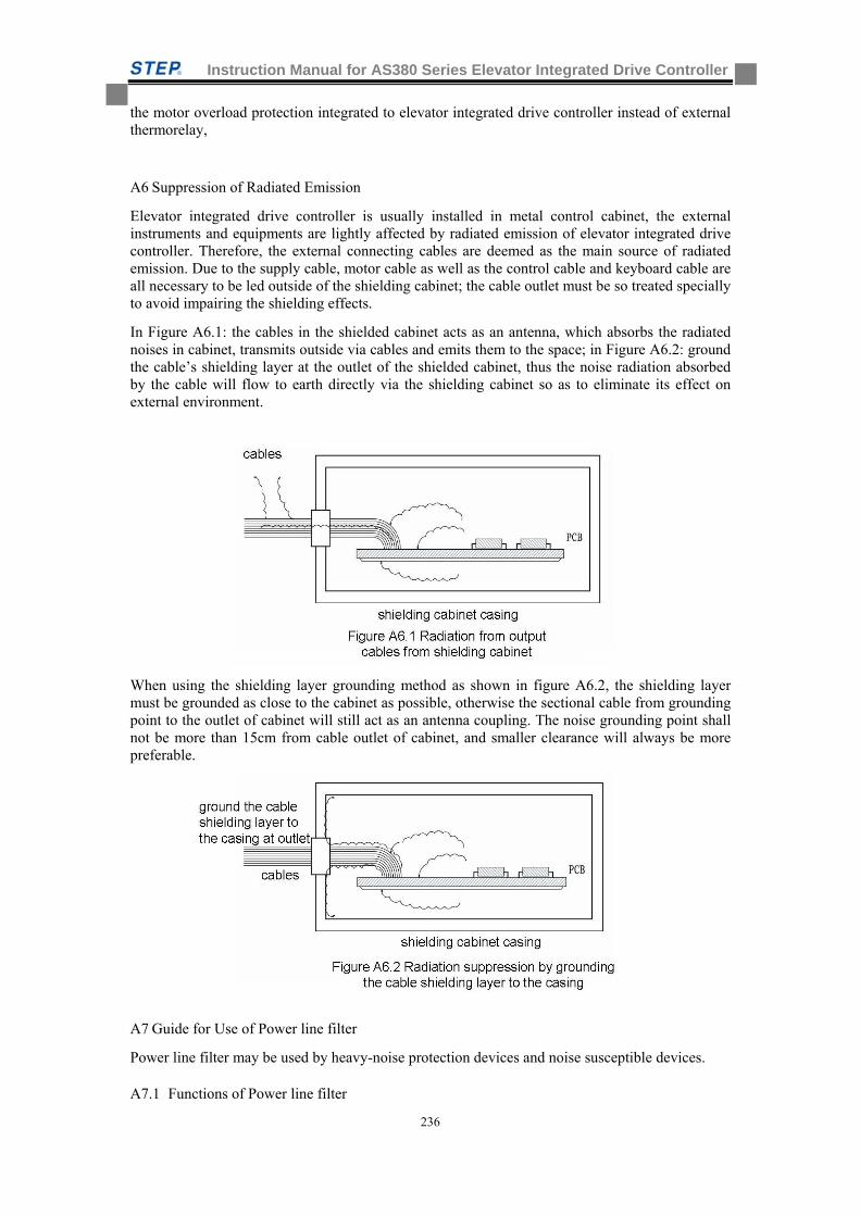
Instruction Manual for AS380 Series Elevator Integrated Drive Controller
236
the motor overload protection integrated to elevator integrated drive controller instead of external thermorelay,
A6 Suppression of Radiated Emission
Elevator integrated drive controller is usually installed in metal control cabinet, the external instruments and equipments are lightly affected by radiated emission of elevator integrated drive controller. Therefore, the external connecting cables are deemed as the main source of radiated emission. Due to the supply cable, motor cable as well as the control cable and keyboard cable are all necessary to be led outside of the shielding cabinet; the cable outlet must be so treated specially to avoid impairing the shielding effects.
In Figure A6.1: the cables in the shielded cabinet acts as an antenna, which absorbs the radiated noises in cabinet, transmits outside via cables and emits them to the space; in Figure A6.2: ground the cable’s shielding layer at the outlet of the shielded cabinet, thus the noise radiation absorbed by the cable will flow to earth directly via the shielding cabinet so as to eliminate its effect on external environment.
When using the shielding layer grounding method as shown in figure A6.2, the shielding layer must be grounded as close to the cabinet as possible, otherwise the sectional cable from grounding point to the outlet of cabinet will still act as an antenna coupling. The noise grounding point shall not be more than 15cm from cable outlet of cabinet, and smaller clearance will always be more preferable.
A7 Guide for Use of Power line filter
Power line filter may be used by heavy-noise protection devices and noise susceptible devices.
A7.1 Functions of Power line filter
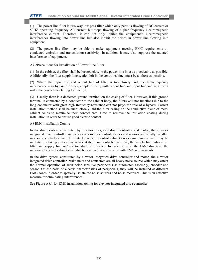
Instruction Manual for AS380 Series Elevator Integrated Drive Controller
237
(1) The power line filter is two-way low pass filter which only permits flowing of DC current or 50HZ operating frequency AC current but stops flowing of higher frequency electromagnetic interference current. Therefore, it can not only inhibit the equipment’s electromagnetic interferences flowing into power line but also inhibit the noises in power line flowing into equipment.
(2) The power line filter may be able to make equipment meeting EMC requirements on conducted emission and transmission sensitivity. In addition, it may also suppress the radiated interference of equipment.
A7.2 Precautions for Installation of Power Line Filter
(1) In the cabinet, the filter shall be located close to the power line inlet as practicably as possible. Additionally, the filter supply line section left in the control cabinet must be as short as possible.
(2) Where the input line and output line of filter is too closely laid, the high-frequency interference may bypass the filter, couple directly with output line and input line and as a result make the power filter failing to function.
(3) Usually there is a dedicated ground terminal on the casing of filter. However, if this ground terminal is connected by a conductor to the cabinet body, the filters will not functions due to the long conductor with great high-frequency resistance can not plays the role of a bypass. Correct installation method shall be such: closely laid the filter casing on the conductive plane of metal cabinet so as to maximize their contact area. Note to remove the insulation coating during installation in order to ensure good electric contact.
A8 EMC Installation Zoning
In the drive system constituted by elevator integrated drive controller and motor, the elevator integrated drive controller and peripherals such as control devices and sensors are usually installed in a same control cabinet. The interferences of control cabinet on external environment may be inhibited by taking suitable measures at the main contacts, therefore, the supply line radio noise filter and supply line AC reactor shall be installed. In order to meet the EMC directive, the interiors of control cabinet shall also be arranged in accordance with EMC requirements.
In the drive system constituted by elevator integrated drive controller and motor, the elevator integrated drive controller, brake units and contactors are all heavy noise source which may affect the normal operation of such noise sensitive peripherals as automated assembly, encoder and sensor. On the basis of electric characteristics of peripherals, they will be installed at different EMC zones in order to spatially isolate the noise sources and noise receivers. This is an effective measure for eliminating interferences.
See Figure A8.1 for EMC installation zoning for elevator integrated drive controller.
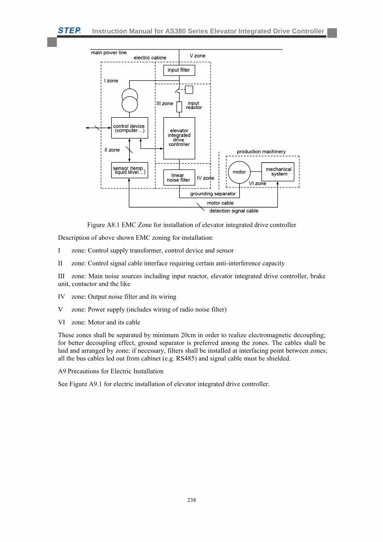
Instruction Manual for AS380 Series Elevator Integrated Drive Controller
238
Figure A8.1 EMC Zone for installation of elevator integrated drive controller
Description of above shown EMC zoning for installation:
I zone: Control supply transformer, control device and sensor
II zone: Control signal cable interface requiring certain anti-interference capacity
III zone: Main noise sources including input reactor, elevator integrated drive controller, brake unit, contactor and the like
IV zone: Output noise filter and its wiring
V zone: Power supply (includes wiring of radio noise filter)
VI zone: Motor and its cable
These zones shall be separated by minimum 20cm in order to realize electromagnetic decoupling; for better decoupling effect, ground separator is preferred among the zones. The cables shall be laid and arranged by zone; if necessary, filters shall be installed at interfacing point between zones; all the bus cables led out from cabinet (e.g. RS485) and signal cable must be shielded.
A9 Precautions for Electric Installation
See Figure A9.1 for electric installation of elevator integrated drive controller.
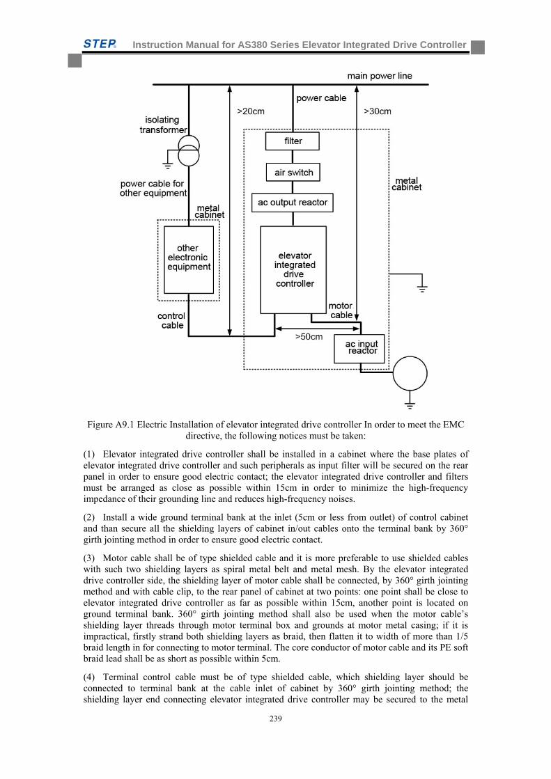
Instruction Manual for AS380 Series Elevator Integrated Drive Controller
239
Figure A9.1 Electric Installation of elevator integrated drive controller In order to meet the EMC directive, the following notices must be taken:
(1) Elevator integrated drive controller shall be installed in a cabinet where the base plates of elevator integrated drive controller and such peripherals as input filter will be secured on the rear panel in order to ensure good electric contact; the elevator integrated drive controller and filters must be arranged as close as possible within 15cm in order to minimize the high-frequency impedance of their grounding line and reduces high-frequency noises.
(2) Install a wide ground terminal bank at the inlet (5cm or less from outlet) of control cabinet and than secure all the shielding layers of cabinet in/out cables onto the terminal bank by 360° girth jointing method in order to ensure good electric contact.
(3) Motor cable shall be of type shielded cable and it is more preferable to use shielded cables with such two shielding layers as spiral metal belt and metal mesh. By the elevator integrated drive controller side, the shielding layer of motor cable shall be connected, by 360° girth jointing method and with cable clip, to the rear panel of cabinet at two points: one point shall be close to elevator integrated drive controller as far as possible within 15cm, another point is located on ground terminal bank. 360° girth jointing method shall also be used when the motor cable’s shielding layer threads through motor terminal box and grounds at motor metal casing; if it is impractical, firstly strand both shielding layers as braid, then flatten it to width of more than 1/5 braid length in for connecting to motor terminal. The core conductor of motor cable and its PE soft braid lead shall be as short as possible within 5cm.
(4) Terminal control cable must be of type shielded cable, which shielding layer should be connected to terminal bank at the cable inlet of cabinet by 360° girth jointing method; the shielding layer end connecting elevator integrated drive controller may be secured to the metal
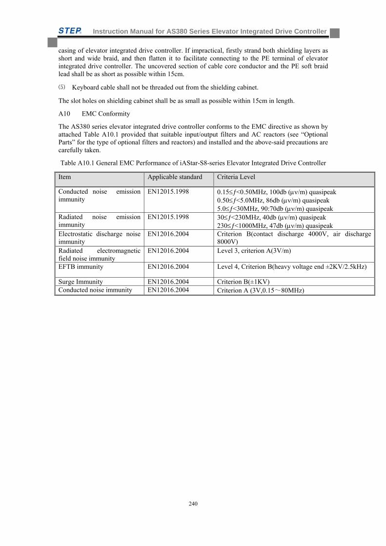
Instruction Manual for AS380 Series Elevator Integrated Drive Controller
240
casing of elevator integrated drive controller. If impractical, firstly strand both shielding layers as short and wide braid, and then flatten it to facilitate connecting to the PE terminal of elevator integrated drive controller. The uncovered section of cable core conductor and the PE soft braid lead shall be as short as possible within 15cm.
⑸ Keyboard cable shall not be threaded out from the shielding cabinet.
The slot holes on shielding cabinet shall be as small as possible within 15cm in length.
A10 EMC Conformity
The AS380 series elevator integrated drive controller conforms to the EMC directive as shown by attached Table A10.1 provided that suitable input/output filters and AC reactors (see “Optional Parts” for the type of optional filters and reactors) and installed and the above-said precautions are carefully taken.
Table A10.1 General EMC Performance of iAStar-S8-series Elevator Integrated Drive Controller
Item Applicable standard Criteria Level
Conducted noise emission immunity
EN12015.1998 0.15<0.50MHz, 100db (/m) quasipeak 0.50<5.0MHz, 86db (/m) quasipeak 5.0<30MHz, 90:70db (/m) quasipeak
Radiated noise emission immunity
EN12015.1998 30<230MHz, 40db (/m) quasipeak 230<1000MHz, 47db (/m) quasipeak
Electrostatic discharge noise immunity
EN12016.2004 Criterion B(contact discharge 4000V, air discharge 8000V)
Radiated electromagnetic field noise immunity
EN12016.2004 Level 3, criterion A(3V/m)
EFTB immunity EN12016.2004 Level 4, Criterion B(heavy voltage end ±2KV/2.5kHz)
Surge Immunity EN12016.2004 Criterion B(±1KV) Conducted noise immunity EN12016.2004 Criterion A (3V,0.15~80MHz)
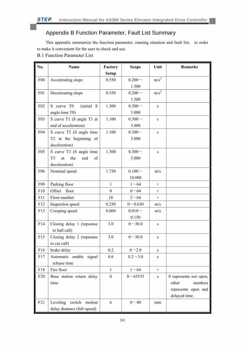
Instruction Manual for AS380 Series Elevator Integrated Drive Controller
241
Appendix B Function Parameter, Fault List Summary
This appendix summarize the function parameter, running situation and fault list, in order
to make it convenient for the user to check and use.
B.1 Function Parameter List
No. Name Factory
Setup
Scope Unit Remarks
F00 Accelerating slope 0.550 0.200~
1.500
m/s2
F01 Decelerating slope 0.550 0.200~
1.500
m/s2
F02 S curve T0 (initial S
angle time T0)
1.300 0.300~
3.000
s
F03 S curve T1 (S angle T1 at
end of acceleration)
1.100 0.300~
3.000
s
F04 S curve T2 (S angle time
T2 at the beginning of
deceleration)
1.100 0.300~
3.000
s
F05 S curve T3 (S angle time
T3 at the end of
deceleration)
1.300 0.300~
3.000
s
F06 Nominal speed 1.750 0.100~
10.000
m/s
F09 Parking floor 1 1~64 ×
F10 Offset floor 0 0~64 ×
F11 Floor number 18 2~64 ×
F12 Inspection speed 0.250 0~0.630 m/s
F13 Creeping speed 0.060 0.010~
0.150
m/s
F14 Closing delay 1 (repsonse
to hall call)
3.0 0~30.0 s
F15 Closing delay 2 (repsonse
to car call)
3.0 0~30.0 s
F16 brake delay 0.2 0~2.0 s
F17 Automatic enable signal
release time
0.6 0.2~3.0 s
F18 Fire floor 1 1~64 ×
F20 Base station return delay
time
0 0~65535 s 0 represents not open;
other numbers
represents open and
delayed time.
F21 Leveling switch motion
delay distance (full-speed)
6 0~40 mm
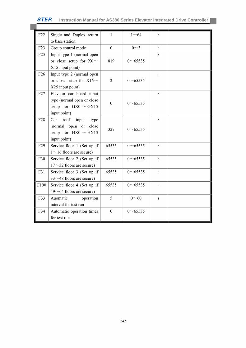
Instruction Manual for AS380 Series Elevator Integrated Drive Controller
242
F22 Single and Duplex return
to base station
1 1~64 ×
F23 Group control mode 0 0~3 ×
F25 Input type 1 (normal open
or close setup for X0~
X15 input point)
819 0~65535
×
F26 Input type 2 (normal open
or close setup for X16~
X25 input point)
2 0~65535
×
F27 Elevator car board input
type (normal open or close
setup for GX0 ~ GX15
input point)
0 0~65535
×
F28 Car roof input type
(normal open or close
setup for HX0 ~ HX15
input point)
327 0~65535
×
F29 Service floor 1 (Set up if
1~16 floors are secure)
65535 0~65535 ×
F30 Service floor 2 (Set up if
17~32 floors are secure)
65535 0~65535 ×
F31 Service floor 3 (Set up if
33~48 floors are secure)
65535 0~65535 ×
F190 Service floor 4 (Set up if
49~64 floors are secure)
65535 0~65535 ×
F33 Auomatic operation
interval for test run
5 0~60 s
F34 Automatic operation times
for test run.
0 0~65535
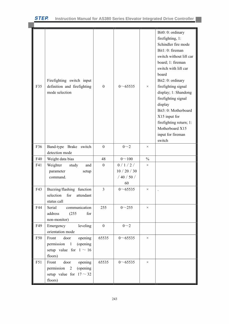
Instruction Manual for AS380 Series Elevator Integrated Drive Controller
243
F35
Firefighting switch input
definition and firefighting
mode selection
0 0~65535 ×
Bit0: 0: ordinary
firefighting, 1:
Schindler fire mode
Bit1: 0: fireman
switch without lift car
board; 1: fireman
switch with lift car
board
Bit2: 0: ordinary
firefighting signal
display; 1: Shandong
firefighting signal
display
Bit3: 0: Motherboard
X15 input for
firefighting return; 1:
Motherboard X15
input for fireman
switch
F36 Band-type Brake switch
detection mode
0 0~2 ×
F40 Weight data bias 48 0~100 %
F41 Weighter study and
parameter setup
command.
0 0/1/2/
10/20/30
/40/50/
60
×
F43 Buzzing/flashing function
selection for attendant
status call
3 0~65535 × .
F44 Serial communication
address (255 for
non-monitor)
255 0~255 ×
F49 Emergency leveling
orientation mode
0 0~2
F50 Front door opening
permission 1 (opening
setup value for 1 ~ 16
floors)
65535 0~65535 ×
F51 Front door opening
permission 2 (opening
setup value for 17 ~ 32
floors)
65535 0~65535 ×
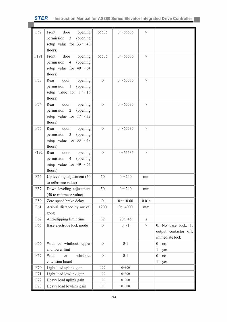
Instruction Manual for AS380 Series Elevator Integrated Drive Controller
244
F52 Front door opening
permission 3 (opening
setup value for 33 ~ 48
floors)
65535 0~65535 ×
F191 Front door opening
permission 4 (opening
setup value for 49 ~ 64
floors)
65535 0~65535 ×
F53 Rear door opening
permission 1 (opening
setup value for 1 ~ 16
floors)
0 0~65535 ×
F54 Rear door opening
permission 2 (opening
setup value for 17 ~ 32
floors)
0 0~65535 ×
F55 Rear door opening
permission 3 (opening
setup value for 33 ~ 48
floors)
0 0~65535 ×
F192 Rear door opening
permission 4 (opening
setup value for 49 ~ 64
floors)
0 0~65535 ×
F56 Up leveling adjustment (50
to refernece value)
50 0~240 mm
F57 Down leveling adjustment
(50 to refernece value)
50 0~240 mm
F59 Zero speed brake delay 0 0~10.00 0.01s
F61 Arrival distance by arrival
gong
1200 0~4000 mm
F62 Anti-slipping limit time 32 20~45 s
F65 Base electrode lock mode 0 0~1 × 0: No base lock, 1:
output contactor off,
immediate lock
F66 With or whithout upper
and lower limt
0 0-1 0:no
1:yes
F67 With or whithout
entension board
0 0-1 0:no
1:yes
F70 Light load uplink gain 100 0-300
F71 Light load lowlink gain 100 0-300
F72 Heavy load uplink gain 100 0-300
F73 Heavy load lowlink gain 100 0-300

Instruction Manual for AS380 Series Elevator Integrated Drive Controller
245
F74 Light load height gain 512 0-1024
F75 Heavy load height gain 512 0-1024
F115 Overtime opening door 15 3~30 s
F116 Overtime closing door 15 3~30 s
F117 Opening time for forced
closing
60 0~1800 s
F118 Opening time for the
disabled
10 0~1800 s
F120 Car call number when
anti-nuisance function
activates.
0 0~30 ×
F121 Activate forced closing
function (0 represents not
activate)
0 0~1 ×
F122 Signal delay release time
in Inspection.
0.3 0~10.0 s
F123 Call categories 0 0~3 x
F124 Define the function of
mainboard X16 input point
0 0~2 ×
F128 Control of front and rear
doors
0 0/1 × 0: separate control of
front and back doors;
1: joint control of
front and back doors
F129 Activate the functions of
re-leveling and/or
pre-opening
0 0~3 ×
F130
Maintain the
opening/closing torque 0 0~7
× Bit0: 1: door
maintaining open
Bit1: 1: door
maintaining closed
Bit2: 1: door
maintaining closed
during operation
F131 Time section floor
blockade floor set 0 0-65535
F132 Time section floor
blockade beginning time
set
0 0-65535
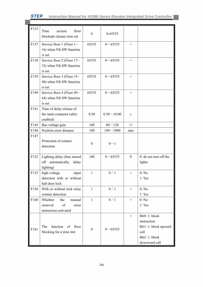
Instruction Manual for AS380 Series Elevator Integrated Drive Controller
246
F133 Time section floor
blockade closure time set 0 0-65535
F137 Service floor 1 (Floor 1~
16) when NS-SW function
is set.
65535 0~65535 ×
F138 Service floor 2 (Floor 17~
32) when NS-SW function
is set.
65535 0~65535 ×
F139 Service floor 3 (Floor 33~
48) when NS-SW function
is set.
65535 0~65535 ×
F199 Service floor 4 (Floor 49~
64) when NS-SW function
is set.
65535 0~65535 ×
F141 Time of delay release of
the main contactor (after
enabled)
0.50 0.50~10.00 s
F145 Bus voltage gain 100 80~120 %
F146 Position error distance 180 180~1000 mm
F147
Protection of contact
detection 0 0~1
F152 Lighting delay (fans turned
off automatically, delay
lighting)
180 0~65535 S 0: do not turn off the
lights
F153 high-voltage input
detection with or without
hall door lock
1 0/1 × 0: No
1: Yes
F156 With or without lock relay
contact detection
1 0/1 × 0: No
1: Yes
F160 Whether the manual
removal of error
instruction activated
1 0/1 × 0: No
1: Yes
F161 The function of floor
blocking for a time slot 0 0~65535
× Bit0: 1: block
instruction
Bit1: 1: block upward
call
Bit2: 1: block
downward call
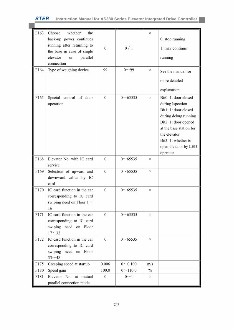
Instruction Manual for AS380 Series Elevator Integrated Drive Controller
247
F163 Choose whether the
back-up power continues
running after returning to
the base in case of single
elevator or parallel
connection
0 0/1
×
0: stop running
1: may continue
running
F164 Type of weighing device 99 0~99 × See the manual for
more detailed
explanation
F165 Special control of door
operation
0 0~65535 × Bit0: 1: door closed
during Ispection
Bit1: 1: door closed
during debug running
Bit2: 1: door opened
at the base station for
the elevator
Bit3: 1: whether to
open the door by LED
operator
F168 Elevator No. with IC card
service
0 0~65535 ×
F169 Selection of upward and
downward callus by IC
card
0 0~65535 ×
F170 IC card function in the car
corresponding to IC card
swiping need on Floor 1~
16
0 0~65535 ×
F171 IC card function in the car
corresponding to IC card
swiping need on Floor
17~32
0 0~65535 ×
F172 IC card function in the car
corresponding to IC card
swiping need on Floor
33~48
0 0~65535 ×
F175 Creeping speed at startup 0.006 0~0.100 m/s
F180 Speed gain 100.0 0~110.0 %
F181 Elevator No. at mutual
parallel connection mode
0 0~1 ×
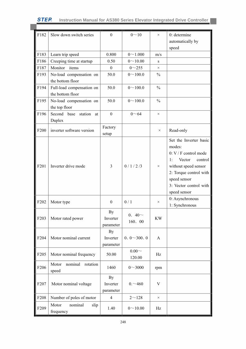
Instruction Manual for AS380 Series Elevator Integrated Drive Controller
248
F182 Slow down switch series 0 0~10 × 0: determine
automatically by
speed
F183 Learn trip speed 0.800 0~1.000 m/s
F186 Creeping time at startup 0.50 0~10.00 s
F187 Monitor items 0 0~255 ×
F193 No-load compensation on
the bottom floor
50.0 0~100.0 %
F194 Full-load compensation on
the bottom floor
50.0 0~100.0 %
F195 No-load compensation on
the top floor
50.0 0~100.0 %
F196 Second base station at
Duplex
0 0~64 ×
F200 inverter software version Factory
setup × Read-only
F201 Inverter drive mode 3 0 / 1 / 2 /3 ×
Set the Inverter basic
modes:
0: V / F control mode
1: Vector control
without speed sensor
2: Torque control with
speed sensor
3: Vector control with
speed sensor
F202 Motor type 0 0 / 1 × 0: Asynchronous
1: Synchronous
F203 Motor rated power
By
Inverter
parameter
0.40~
160.00 KW
F204 Motor nominal current
By
Inverter
parameter
0.0~300.0 A
F205 Motor nominal frequency 50.00 0.00~
120.00 Hz
F206 Motor nominal rotation
speed 1460 0~3000 rpm
F207 Motor nominal voltage
By
Inverter
parameter
0.~460 V
F208 Number of poles of motor 4 2~128 ×
F209 Motor nominal slip
frequency 1.40 0~10.00 Hz

Instruction Manual for AS380 Series Elevator Integrated Drive Controller
249
F210 Encoder type 0 0 / 1 / 2 ×
0: incremental
Encoder
1: SIN/ COS Encoder
2: Endat Encoder
F211 Encoder pulse number 1024 500~16000 PPr
F212 Zero speed PID adjustor
incremental P0 130.00
0.00~
655.35 ×
F213 Zero speed PID adjustor
integral I0 80.00
0.00~
655.35
×
F214 Zero speed PID adjustor
differential D0 0.50
0.00 ~
655.35
×
F215 Low speed PID adjustor
incremental P1 70.00
0.00 ~
655.35
×
F216 Low speed PID adjustor
integral I1 30.00
0.00 ~
655.35
×
F217 Low speed PID adjustor
differential D1 0.50
0.00 ~
655.35
×
F218 Medium speed PID
adjustor incremental P2 120.00
0.00 ~
655.35
×
F219 Medium speed PID
adjustor integral I2 25.00
0.00 ~
655.35
×
F220 Medium speed PID
adjustor differential D2 0.20
0.00 ~
655.35
×
F221 High speed PID adjustor
incremental P3 140.00
0.00 ~
655.35
×
F222 High speed PID adjustor
integral I3 5.00
0.00 ~
655.35
×
F223 High speed PID adjustor
differential D3 0.10
0.00 ~
655.35 ×
F224 Low speed point switch
frequency F0 1.0 0.0~100.0 %
F225 High speed point switch
frequency F0 50.0 0.0~100.0 %
F226 Zero servo time 0.5 0.0~30.0 s
F227 Band-type Brake release
time 0.25 0.00~30.00 s
F228 Current slowdown time 0.00 0.00~10.00 s
F229 Torque compensation
direction 0 0/1 ×
0:positive direction
1:negative direction
F230 Torque compensation gain 100.0 0.0~200.0 %
F231 Torque compensation bias 0.0 0.0~100.0 %
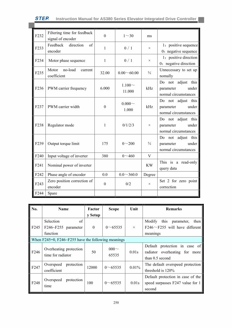
Instruction Manual for AS380 Series Elevator Integrated Drive Controller
250
F232 Filtering time for feedback
signal of encoder 0 1~30 ms
F233 Feedback direction of
encoder 1 0/1 ×
1:positive sequence
0:negative sequence
F234 Motor phase sequence 1 0/1 × 1:positive direction
0:negative direction
F235 Motor no-load current
coefficient 32.00 0.00~60.00 %
Unnecessary to set up
nomally
F236 PWM carrier frequency 6.000 1.100~
11.000 kHz
Do not adjust this
parameter under
normal circumstances
F237 PWM carrier width 0 0.000~
1.000 kHz
Do not adjust this
parameter under
normal circumstances
F238 Regulator mode 1 0/1/2/3 ×
Do not adjust this
parameter under
normal circumstances
F239 Output torque limit 175 0~200 %
Do not adjust this
parameter under
normal circumstances
F240 Input voltage of inverter 380 0~460 V
F241 Nominal power of inverter KW This is a read-only
query data
F242 Phase angle of encoder 0.0 0.0~360.0 Degree
F243 Zero position correction of
encoder 0 0/2 ×
Set 2 for zero point
correction
F244 Spare
No. Name Factor
y Setup
Scope Unit Remarks
F245
Selection of
F246~F255 parameter
function
0 0~65535 ×
Modify this parameter, then
F246~F255 will have different
meanings
When F245=0, F246~F255 have the following meanings
F246 Overheating protection
time for radiator 50
000~
65535 0.01s
Default protection in case of
radiator overheating for more
than 0.5 second
F247 Overspeed protection
coefficient 12000 0~65535 0.01%
The default overspeed protection
threshold is 120%
F248 Overspeed protection
time 100 0~65535 0.01s
Default protection in case of the
speed surpasses F247 value for 1
second

Instruction Manual for AS380 Series Elevator Integrated Drive Controller
251
F249 Confirmation times for
inputting open phase 35 0~65535 Time
Default protection in case of
inputting open phase for more
than 35 times in a given moment
F250
Confirmation times for
short circuit of braking
resistor
10 0~65535 Time
Default protection in case of short
circuit of braking resistor for
more than 10 times in a given
moment
F251
Confirmation times for
SinCos Encoder
disconnection
2 0~65535 Time
Default protection in case of
SinCos Encoder disconnection
confirmed for more than twice
F252 Confirmation times for
outputting open phase 2000 0~65535 0.001s
Default protection in case of
outputting open phase confirmed
for more than 2 second
F253
Confirmation of
voltage for charging
relay failure
65 0~65535 Volt
Protection after the three-phase
in-operation input voltage
reduces to 65/1.414 = 46V, 144
failure reported, the charging
relay may be damaged or the grid
voltage is suddenly decreased.
F254
Confirmation
threshold of Encoder
phase CD failure
300 0~65535
No 28 failure reported in case
that the D-value of the absolute
position and computing position
of encoder exceed the setting
value.
F255
Protection threshold of
ABZ encoder
disconnection
20 0~100
Protection in case of speed
feedback deviation of
synchronous motor confirmed for
more than the setting value
When F245=1, F246~F255 have the following meanings
F246 Protection times of
IGBT 2 0~65535 Times
Times of Instantaneous over
current of IGBT
F247 Protection option of
I2t 0 0/1/2
0:two ways of I2t
protection,1:only the first way of
I2t protection,2: only the second
way of I2t protection
F248 Spare
F249 Spare
F250 Spare
F251 Spare
F252 Spare
F253 Spare
F254 Spare
F255 Spare

Instruction Manual for AS380 Series Elevator Integrated Drive Controller
252
When F245=2, F246~F255 have the following meanings
F246 Spare Internal test parameters, do not
modify
F247 PWM modulation
mode 2 0~2 ×
0: 5 segment; 1: 7 segment; 2: <
40% rpm 7 segments, > 40% 5
segments
At low speed, the AIO has too
much interference toward
outside. For example, when CAN
has a poor communication signal,
the change to 0 (5 segments) will
have significant effect, and it will
reduce the heat of the drive, but
may cause too much noise
for inverter at low speed.
F248 Spare Internal test parameters, do not
modify
F249 Spare Internal test parameters, do not
modify
F250 Three-phase current
balance coefficient ×
Read-only, the calibration factor
of three-phase current balance
coefficient will automatically
change. The synchronous motor
may trigger the self study
command of the asynchronous
motor to output contactor, and
carry out the calibration of the
three-phase current balance
coefficient. Such function will
reduce the motor vibration and
improve comfort.
F251 Spare
F252 Positive /negtive
rotation enabled 0 0~60000 0.1s
0:allow Positive /negtive rotation
1:only allow positive rotation
F253 Position /negtive
rotation dead-time 20 0~200 %
The zero-speed time of
positive/negative rotation change
F254
Accelerating
overcurrent threshold
of inverter
180 0~200 %
Inverter stop accelerating and
maintain the current speed if
overcurrent occur during the
acceleration process, then
continue to accelerate once the
current drop.
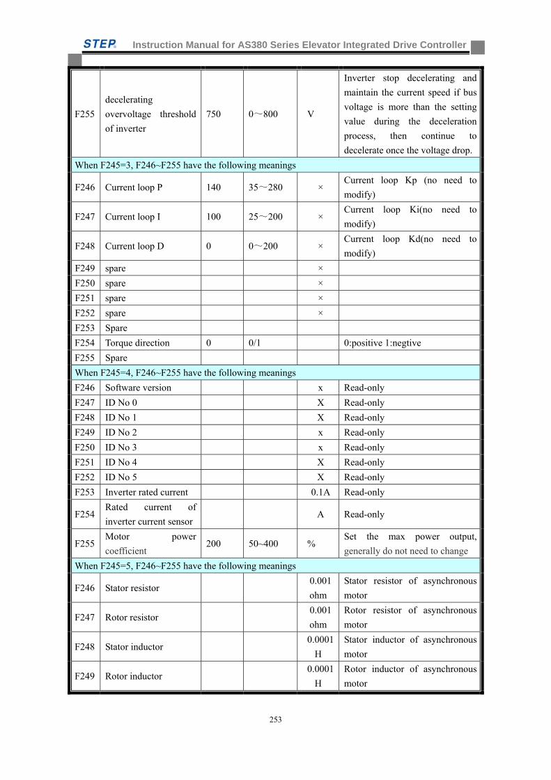
Instruction Manual for AS380 Series Elevator Integrated Drive Controller
253
F255
decelerating
overvoltage threshold
of inverter
750 0~800 V
Inverter stop decelerating and
maintain the current speed if bus
voltage is more than the setting
value during the deceleration
process, then continue to
decelerate once the voltage drop.
When F245=3, F246~F255 have the following meanings
F246 Current loop P 140 35~280 × Current loop Kp (no need to
modify)
F247 Current loop I 100 25~200 × Current loop Ki(no need to
modify)
F248 Current loop D 0 0~200 × Current loop Kd(no need to
modify)
F249 spare ×
F250 spare ×
F251 spare ×
F252 spare ×
F253 Spare
F254 Torque direction 0 0/1 0:positive 1:negtive
F255 Spare
When F245=4, F246~F255 have the following meanings
F246 Software version x Read-only
F247 ID No 0 X Read-only
F248 ID No 1 X Read-only
F249 ID No 2 x Read-only
F250 ID No 3 x Read-only
F251 ID No 4 X Read-only
F252 ID No 5 X Read-only
F253 Inverter rated current 0.1A Read-only
F254 Rated current of
inverter current sensor A Read-only
F255 Motor power
coefficient 200 50~400 %
Set the max power output,
generally do not need to change
When F245=5, F246~F255 have the following meanings
F246 Stator resistor 0.001
ohm
Stator resistor of asynchronous
motor
F247 Rotor resistor 0.001
ohm
Rotor resistor of asynchronous
motor
F248 Stator inductor 0.0001
H
Stator inductor of asynchronous
motor
F249 Rotor inductor 0.0001
H
Rotor inductor of asynchronous
motor
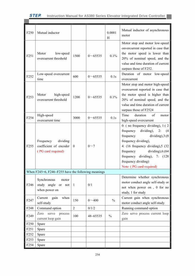
Instruction Manual for AS380 Series Elevator Integrated Drive Controller
254
F250 Mutual inductor
0.0001
H
Mutual inductor of asynchronous
motor
F251 Motor low-speed
overcurrent threshold 1500 0~65535 0.1%
Motor stop and motor low-speed
onvercurrent reported in case that
the motor speed is lower than
20% of nominal speed, and the
value and time duration of current
surpass those of F252.
F252 Low-speed overcurrent
time 600 0~65535 0.1s
Duration of motor low-speed
overcurrent
F253 Motor high-speed
overcurrent threshold 1200 0~65535 0.1%
Motor stop and motor high-speed
overcurrent reported in case that
the motor speed is higher than
20% of nominal speed, and the
value and time duration of current
surpass those of F2524
F254 High-speed
overcurrent time 3000 0~65535 0.1s
Time duration of motor
high-speed overcurrent
F255
Frequency dividing
coefficient of encoder
( PG card required)
0 0~7
0: ( no frequency dividing), 1:( 2
frequency dividing), 2: (4
frequency dividing),3:(8
frequency dividing),
4: (16 frequency dividing),5 (32
frequency dividing),6:(64
frequency dividing), 7: (128
frequency dividing)
Note: ( PG card required)
When F245=6, F246~F255 have the following meanings
F246
Synchronous motor
study angle or not
when power on
1 0/1
Determine whether synchronous
motor conduct angle self-study or
not when power on , 0 for no
study, 1 for study
F247 Current gain when
self-study 150 0~400 %
Current gain when synchronous
motor conduct angle self-study
F248 Command option 2 0/1/2 Running command option
F249 Zero servo process
current loop gain 100 48~65535 %
Zero servo process current loop
gain
F250 Spare
F251 Spare
F252 Spare
F253 Spare
F254 Spare
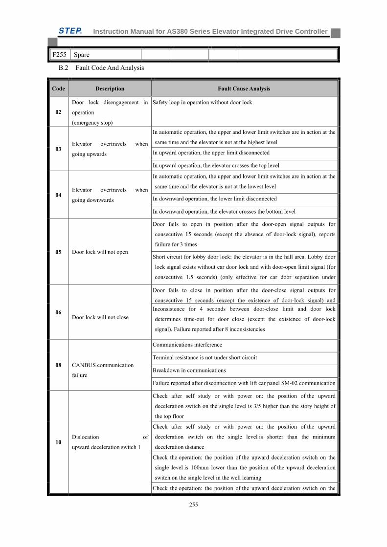
Instruction Manual for AS380 Series Elevator Integrated Drive Controller
255
F255 Spare
B.2 Fault Code And Analysis
Code Description Fault Cause Analysis
02
Door lock disengagement in
operation
(emergency stop)
Safety loop in operation without door lock
03 Elevator overtravels when
going upwards
In automatic operation, the upper and lower limit switches are in action at the
same time and the elevator is not at the highest level
In upward operation, the upper limit disconnected
In upward operation, the elevator crosses the top level
04 Elevator overtravels when
going downwards
In automatic operation, the upper and lower limit switches are in action at the
same time and the elevator is not at the lowest level
In downward operation, the lower limit disconnected
In downward operation, the elevator crosses the bottom level
05 Door lock will not open
Door fails to open in position after the door-open signal outputs for
consecutive 15 seconds (except the absence of door-lock signal), reports
failure for 3 times
Short circuit for lobby door lock: the elevator is in the hall area. Lobby door
lock signal exists without car door lock and with door-open limit signal (for
consecutive 1.5 seconds) (only effective for car door separation under
06
Door lock will not close
Door fails to close in position after the door-close signal outputs for
consecutive 15 seconds (except the existence of door-lock signal) and
Inconsistence for 4 seconds between door-close limit and door lock
determines time-out for door close (except the existence of door-lock
signal). Failure reported after 8 inconsistencies
08
CANBUS communication
failure
Communications interference
Terminal resistance is not under short circuit
Breakdown in communications
Failure reported after disconnection with lift car panel SM-02 communication
10 Dislocation of
upward deceleration switch 1
Check after self study or with power on: the position of the upward
deceleration switch on the single level is 3/5 higher than the story height of
the top floor
Check after self study or with power on: the position of the upward
deceleration switch on the single level is shorter than the minimum
deceleration distance
Check the operation: the position of the upward deceleration switch on the
single level is 100mm lower than the position of the upward deceleration
switch on the single level in the well learning
Check the operation: the position of the upward deceleration switch on the
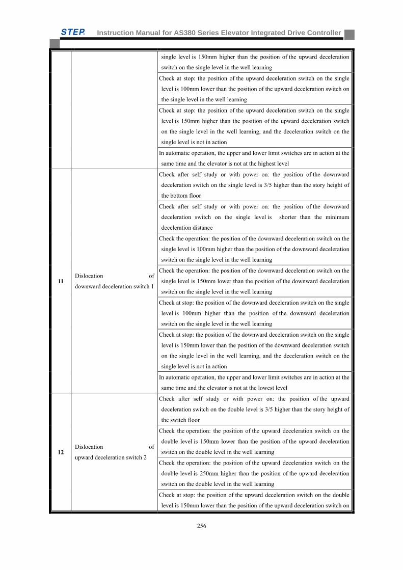
Instruction Manual for AS380 Series Elevator Integrated Drive Controller
256
single level is 150mm higher than the position of the upward deceleration
switch on the single level in the well learning
Check at stop: the position of the upward deceleration switch on the single
level is 100mm lower than the position of the upward deceleration switch on
the single level in the well learning
Check at stop: the position of the upward deceleration switch on the single
level is 150mm higher than the position of the upward deceleration switch
on the single level in the well learning, and the deceleration switch on the
single level is not in action
In automatic operation, the upper and lower limit switches are in action at the
same time and the elevator is not at the highest level
11 Dislocation of
downward deceleration switch 1
Check after self study or with power on: the position of the downward
deceleration switch on the single level is 3/5 higher than the story height of
the bottom floor
Check after self study or with power on: the position of the downward
deceleration switch on the single level is shorter than the minimum
deceleration distance
Check the operation: the position of the downward deceleration switch on the
single level is 100mm higher than the position of the downward deceleration
switch on the single level in the well learning
Check the operation: the position of the downward deceleration switch on the
single level is 150mm lower than the position of the downward deceleration
switch on the single level in the well learning
Check at stop: the position of the downward deceleration switch on the single
level is 100mm higher than the position of the downward deceleration
switch on the single level in the well learning
Check at stop: the position of the downward deceleration switch on the single
level is 150mm lower than the position of the downward deceleration switch
on the single level in the well learning, and the deceleration switch on the
single level is not in action
In automatic operation, the upper and lower limit switches are in action at the
same time and the elevator is not at the lowest level
12 Dislocation of
upward deceleration switch 2
Check after self study or with power on: the position of the upward
deceleration switch on the double level is 3/5 higher than the story height of
the switch floor
Check the operation: the position of the upward deceleration switch on the
double level is 150mm lower than the position of the upward deceleration
switch on the double level in the well learning
Check the operation: the position of the upward deceleration switch on the
double level is 250mm higher than the position of the upward deceleration
switch on the double level in the well learning
Check at stop: the position of the upward deceleration switch on the double
level is 150mm lower than the position of the upward deceleration switch on
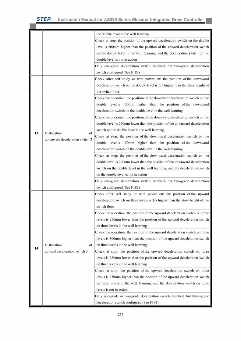
Instruction Manual for AS380 Series Elevator Integrated Drive Controller
257
the double level in the well learning
Check at stop: the position of the upward deceleration switch on the double
level is 200mm higher than the position of the upward deceleration switch
on the double level in the well learning, and the deceleration switch on the
double level is not in action
Only one-grade deceleration switch installed, but two-grade deceleration
switch configured (See F182)
13
Dislocation of
downward deceleration switch 2
Check after self study or with power on: the position of the downward
deceleration switch on the double level is 3/5 higher than the story height of
the switch floor
Check the operation: the position of the downward deceleration switch on the
double level is 150mm higher than the position of the downward
deceleration switch on the double level in the well learning
Check the operation: the position of the downward deceleration switch on the
double level is 250mm lower than the position of the downward deceleration
switch on the double level in the well learning
Check at stop: the position of the downward deceleration switch on the
double level is 150mm higher than the position of the downward
deceleration switch on the double level in the well learning
Check at stop: the position of the downward deceleration switch on the
double level is 200mm lower than the position of the downward deceleration
switch on the double level in the well learning, and the deceleration switch
on the double level is not in action
Only one-grade deceleration switch installed, but two-grade deceleration
switch configured (See F182)
14 Dislocation of
upward deceleration switch 3
Check after self study or with power on: the position of the upward
deceleration switch on three levels is 3/5 higher than the story height of the
switch floor
Check the operation: the position of the upward deceleration switch on three
levels is 250mm lower than the position of the upward deceleration switch
on three levels in the well learning
Check the operation: the position of the upward deceleration switch on three
levels is 300mm higher than the position of the upward deceleration switch
on three levels in the well learning
Check at stop: the position of the upward deceleration switch on three
levels is 250mm lower than the position of the upward deceleration switch
on three levels in the well learning
Check at stop: the position of the upward deceleration switch on three
levels is 250mm higher than the position of the upward deceleration switch
on three levels in the well learning, and the deceleration switch on three
levels is not in action
Only one-grade or two-grade deceleration switch installed, but three-grade
deceleration switch configured (See F182)
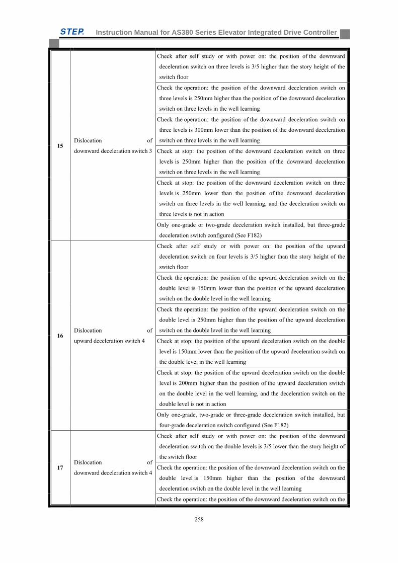
Instruction Manual for AS380 Series Elevator Integrated Drive Controller
258
15 Dislocation of
downward deceleration switch 3
Check after self study or with power on: the position of the downward
deceleration switch on three levels is 3/5 higher than the story height of the
switch floor
Check the operation: the position of the downward deceleration switch on
three levels is 250mm higher than the position of the downward deceleration
switch on three levels in the well learning
Check the operation: the position of the downward deceleration switch on
three levels is 300mm lower than the position of the downward deceleration
switch on three levels in the well learning
Check at stop: the position of the downward deceleration switch on three
levels is 250mm higher than the position of the downward deceleration
switch on three levels in the well learning
Check at stop: the position of the downward deceleration switch on three
levels is 250mm lower than the position of the downward deceleration
switch on three levels in the well learning, and the deceleration switch on
three levels is not in action
Only one-grade or two-grade deceleration switch installed, but three-grade
deceleration switch configured (See F182)
16 Dislocation of
upward deceleration switch 4
Check after self study or with power on: the position of the upward
deceleration switch on four levels is 3/5 higher than the story height of the
switch floor
Check the operation: the position of the upward deceleration switch on the
double level is 150mm lower than the position of the upward deceleration
switch on the double level in the well learning
Check the operation: the position of the upward deceleration switch on the
double level is 250mm higher than the position of the upward deceleration
switch on the double level in the well learning
Check at stop: the position of the upward deceleration switch on the double
level is 150mm lower than the position of the upward deceleration switch on
the double level in the well learning
Check at stop: the position of the upward deceleration switch on the double
level is 200mm higher than the position of the upward deceleration switch
on the double level in the well learning, and the deceleration switch on the
double level is not in action
Only one-grade, two-grade or three-grade deceleration switch installed, but
four-grade deceleration switch configured (See F182)
17 Dislocation of
downward deceleration switch 4
Check after self study or with power on: the position of the downward
deceleration switch on the double levels is 3/5 lower than the story height of
the switch floor
Check the operation: the position of the downward deceleration switch on the
double level is 150mm higher than the position of the downward
deceleration switch on the double level in the well learning
Check the operation: the position of the downward deceleration switch on the
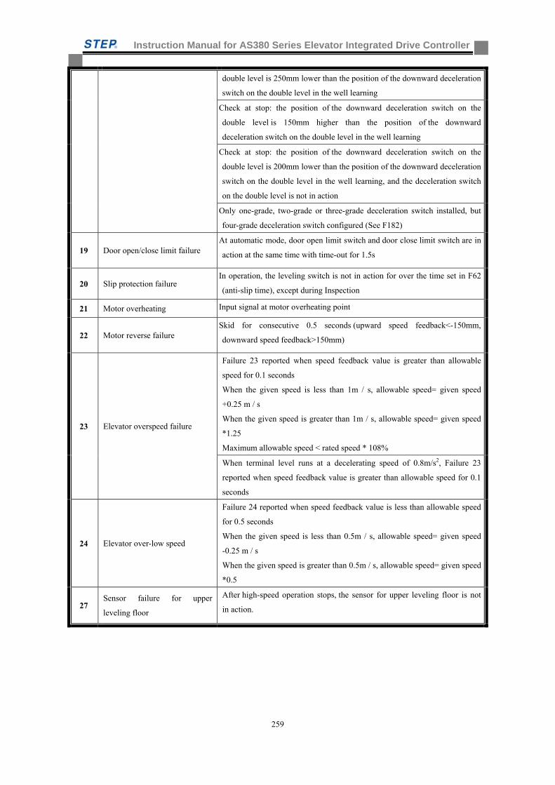
Instruction Manual for AS380 Series Elevator Integrated Drive Controller
259
double level is 250mm lower than the position of the downward deceleration
switch on the double level in the well learning
Check at stop: the position of the downward deceleration switch on the
double level is 150mm higher than the position of the downward
deceleration switch on the double level in the well learning
Check at stop: the position of the downward deceleration switch on the
double level is 200mm lower than the position of the downward deceleration
switch on the double level in the well learning, and the deceleration switch
on the double level is not in action
Only one-grade, two-grade or three-grade deceleration switch installed, but
four-grade deceleration switch configured (See F182)
19 Door open/close limit failure At automatic mode, door open limit switch and door close limit switch are in
action at the same time with time-out for 1.5s
20 Slip protection failure In operation, the leveling switch is not in action for over the time set in F62
(anti-slip time), except during Inspection
21 Motor overheating Input signal at motor overheating point
22 Motor reverse failure Skid for consecutive 0.5 seconds (upward speed feedback<-150mm,
downward speed feedback>150mm)
23 Elevator overspeed failure
Failure 23 reported when speed feedback value is greater than allowable
speed for 0.1 seconds
When the given speed is less than 1m / s, allowable speed= given speed
+0.25 m / s
When the given speed is greater than 1m / s, allowable speed= given speed
*1.25
Maximum allowable speed < rated speed * 108%
When terminal level runs at a decelerating speed of 0.8m/s2, Failure 23
reported when speed feedback value is greater than allowable speed for 0.1
seconds
24 Elevator over-low speed
Failure 24 reported when speed feedback value is less than allowable speed
for 0.5 seconds
When the given speed is less than 0.5m / s, allowable speed= given speed
-0.25 m / s
When the given speed is greater than 0.5m / s, allowable speed= given speed
*0.5
27 Sensor failure for upper
leveling floor
After high-speed operation stops, the sensor for upper leveling floor is not
in action.
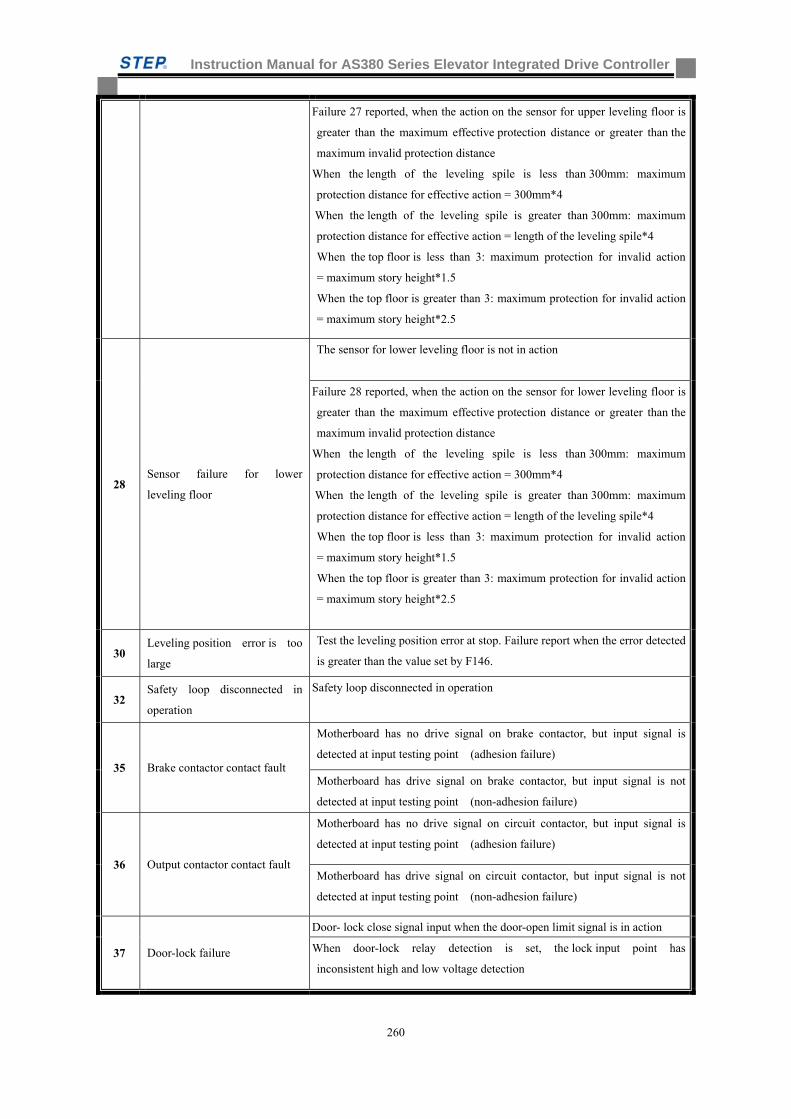
Instruction Manual for AS380 Series Elevator Integrated Drive Controller
260
Failure 27 reported, when the action on the sensor for upper leveling floor is
greater than the maximum effective protection distance or greater than the
maximum invalid protection distance
When the length of the leveling spile is less than 300mm: maximum
protection distance for effective action = 300mm*4
When the length of the leveling spile is greater than 300mm: maximum
protection distance for effective action = length of the leveling spile*4
When the top floor is less than 3: maximum protection for invalid action
= maximum story height*1.5
When the top floor is greater than 3: maximum protection for invalid action
= maximum story height*2.5
28 Sensor failure for lower
leveling floor
The sensor for lower leveling floor is not in action
Failure 28 reported, when the action on the sensor for lower leveling floor is
greater than the maximum effective protection distance or greater than the
maximum invalid protection distance
When the length of the leveling spile is less than 300mm: maximum
protection distance for effective action = 300mm*4
When the length of the leveling spile is greater than 300mm: maximum
protection distance for effective action = length of the leveling spile*4
When the top floor is less than 3: maximum protection for invalid action
= maximum story height*1.5
When the top floor is greater than 3: maximum protection for invalid action
= maximum story height*2.5
30 Leveling position error is too
large
Test the leveling position error at stop. Failure report when the error detected
is greater than the value set by F146.
32 Safety loop disconnected in
operation
Safety loop disconnected in operation
35 Brake contactor contact fault
Motherboard has no drive signal on brake contactor, but input signal is
detected at input testing point (adhesion failure)
Motherboard has drive signal on brake contactor, but input signal is not
detected at input testing point (non-adhesion failure)
36 Output contactor contact fault
Motherboard has no drive signal on circuit contactor, but input signal is
detected at input testing point (adhesion failure)
Motherboard has drive signal on circuit contactor, but input signal is not
detected at input testing point (non-adhesion failure)
37 Door-lock failure
Door- lock close signal input when the door-open limit signal is in action
When door-lock relay detection is set, the lock input point has
inconsistent high and low voltage detection
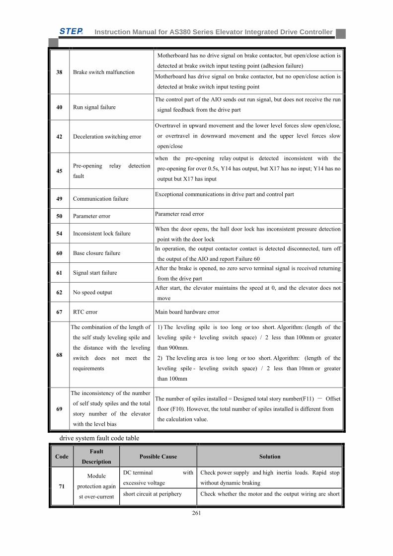
Instruction Manual for AS380 Series Elevator Integrated Drive Controller
261
38 Brake switch malfunction
Motherboard has no drive signal on brake contactor, but open/close action is
detected at brake switch input testing point (adhesion failure)
Motherboard has drive signal on brake contactor, but no open/close action is
detected at brake switch input testing point
40 Run signal failure The control part of the AIO sends out run signal, but does not receive the run
signal feedback from the drive part
42 Deceleration switching error
Overtravel in upward movement and the lower level forces slow open/close,
or overtravel in downward movement and the upper level forces slow
open/close
45 Pre-opening relay detection
fault
when the pre-opening relay output is detected inconsistent with the
pre-opening for over 0.5s, Y14 has output, but X17 has no input; Y14 has no
output but X17 has input
49 Communication failure Exceptional communications in drive part and control part
50 Parameter error Parameter read error
54 Inconsistent lock failure When the door opens, the hall door lock has inconsistent pressure detection
point with the door lock
60 Base closure failure In operation, the output contactor contact is detected disconnected, turn off
the output of the AIO and report Failure 60
61 Signal start failure After the brake is opened, no zero servo terminal signal is received returning
from the drive part
62 No speed output After start, the elevator maintains the speed at 0, and the elevator does not
move
67 RTC error Main board hardware error
68
The combination of the length of
the self study leveling spile and
the distance with the leveling
switch does not meet the
requirements
1) The leveling spile is too long or too short. Algorithm: (length of the
leveling spile + leveling switch space) / 2 less than 100mm or greater
than 900mm.
2) The leveling area is too long or too short. Algorithm: (length of the
leveling spile - leveling switch space) / 2 less than 10mm or greater
than 100mm
69
The inconsistency of the number
of self study spiles and the total
story number of the elevator
with the level bias
The number of spiles installed = Designed total story number(F11) - Offset
floor (F10). However, the total number of spiles installed is different from
the calculation value.
drive system fault code table
Code Fault
Description Possible Cause Solution
71
Module
protection again
st over-current
DC terminal with
excessive voltage
Check power supply and high inertia loads. Rapid stop
without dynamic braking
short circuit at periphery Check whether the motor and the output wiring are short
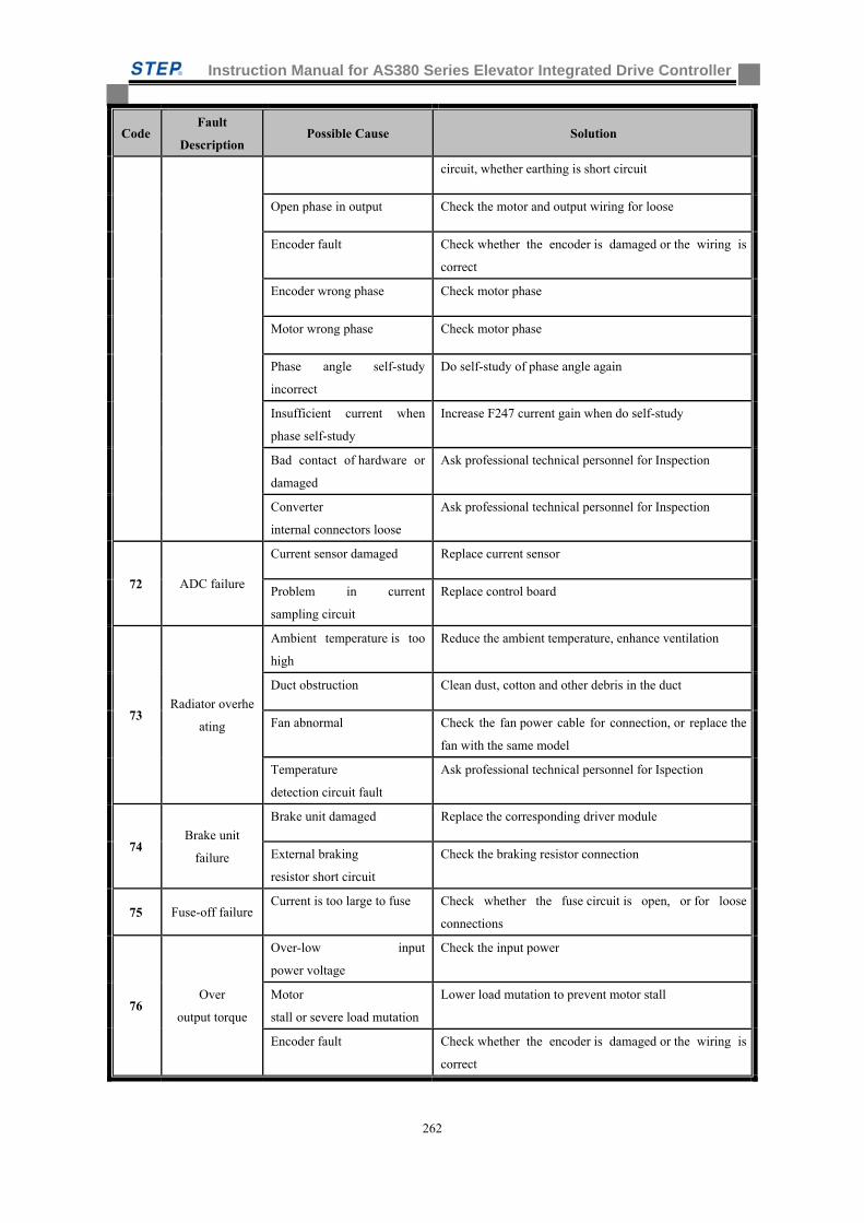
Instruction Manual for AS380 Series Elevator Integrated Drive Controller
262
Code Fault
Description Possible Cause Solution
circuit, whether earthing is short circuit
Open phase in output Check the motor and output wiring for loose
Encoder fault Check whether the encoder is damaged or the wiring is
correct
Encoder wrong phase Check motor phase
Motor wrong phase Check motor phase
Phase angle self-study
incorrect
Do self-study of phase angle again
Insufficient current when
phase self-study
Increase F247 current gain when do self-study
Bad contact of hardware or
damaged
Ask professional technical personnel for Inspection
Converter
internal connectors loose
Ask professional technical personnel for Inspection
72 ADC failure
Current sensor damaged Replace current sensor
Problem in current
sampling circuit
Replace control board
73 Radiator overhe
ating
Ambient temperature is too
high
Reduce the ambient temperature, enhance ventilation
Duct obstruction Clean dust, cotton and other debris in the duct
Fan abnormal Check the fan power cable for connection, or replace the
fan with the same model
Temperature
detection circuit fault
Ask professional technical personnel for Ispection
74 Brake unit
failure
Brake unit damaged Replace the corresponding driver module
External braking
resistor short circuit
Check the braking resistor connection
75 Fuse-off failure Current is too large to fuse Check whether the fuse circuit is open, or for loose
connections
76 Over
output torque
Over-low input
power voltage
Check the input power
Motor
stall or severe load mutation
Lower load mutation to prevent motor stall
Encoder fault Check whether the encoder is damaged or the wiring is
correct
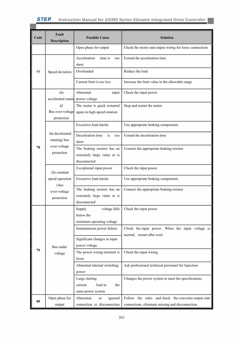
Instruction Manual for AS380 Series Elevator Integrated Drive Controller
263
Code Fault
Description Possible Cause Solution
Open phase for output Check the motor and output wiring for loose connections
77 Speed deviation
Acceleration time is too
short
Extend the acceleration time
Overloaded Reduce the load
Current limit is too low Increase the limit value in the allowable range
78
(In
accelerated runnin
g)
Bus over-voltage
protection
Abnormal input
power voltage
Check the input power
The motor is quick restarted
again in high-speed rotation
Stop and restart the motor
(In decelerated
running) bus
over-voltage
protection
Excessive load inertia Use appropriate braking components
Deceleration time is too
short
Extend the deceleration time
The braking resistor has an
extremely large value or is
disconnected
Connect the appropriate braking resistor
(In constant
speed operation
) bus
over-voltage
protection
Exceptional input power Check the input power
Excessive load inertia Use appropriate braking components
The braking resistor has an
extremely large value or is
disconnected
Connect the appropriate braking resistor
79 Bus under
voltage
Supply voltage falls
below the
minimum operating voltage
Check the input power
Instantaneous power failure Check the input power. When the input voltage is
normal, restart after reset Significant changes in input
power voltage
The power wiring terminal is
loose
Check the input wiring
Abnormal internal switching
power
Ask professional technical personnel for Ispection
Large starting
current load in the
same power system
Changes the power system to meet the specifications
80 Open phase for
output
Abnormal, or ignored
connection or disconnection
Follow the rules and check the converter output side
connections, eliminate missing and disconnection
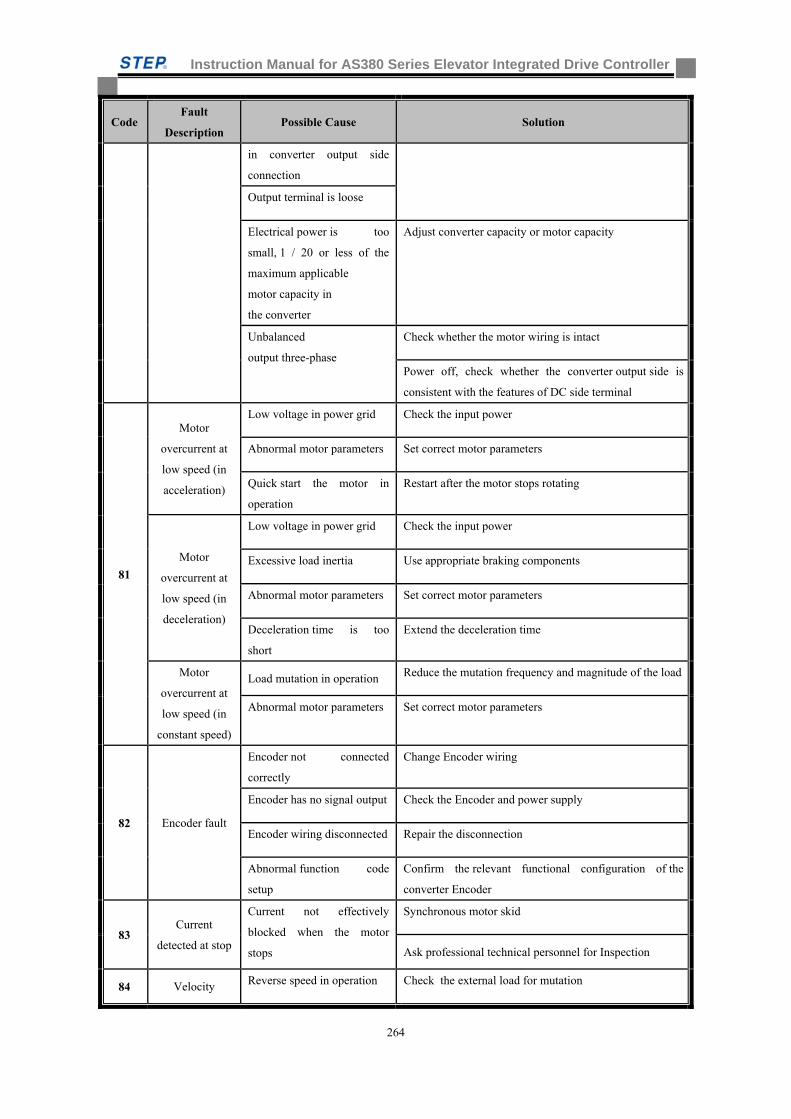
Instruction Manual for AS380 Series Elevator Integrated Drive Controller
264
Code Fault
Description Possible Cause Solution
in converter output side
connection
Output terminal is loose
Electrical power is too
small, 1 / 20 or less of the
maximum applicable
motor capacity in
the converter
Adjust converter capacity or motor capacity
Unbalanced
output three-phase
Check whether the motor wiring is intact
Power off, check whether the converter output side is
consistent with the features of DC side terminal
81
Motor
overcurrent at
low speed (in
acceleration)
Low voltage in power grid Check the input power
Abnormal motor parameters Set correct motor parameters
Quick start the motor in
operation
Restart after the motor stops rotating
Motor
overcurrent at
low speed (in
deceleration)
Low voltage in power grid Check the input power
Excessive load inertia Use appropriate braking components
Abnormal motor parameters Set correct motor parameters
Deceleration time is too
short
Extend the deceleration time
Motor
overcurrent at
low speed (in
constant speed)
Load mutation in operation Reduce the mutation frequency and magnitude of the load
Abnormal motor parameters Set correct motor parameters
82 Encoder fault
Encoder not connected
correctly
Change Encoder wiring
Encoder has no signal output Check the Encoder and power supply
Encoder wiring disconnected Repair the disconnection
Abnormal function code
setup
Confirm the relevant functional configuration of the
converter Encoder
83 Current
detected at stop
Current not effectively
blocked when the motor
stops
Synchronous motor skid
Ask professional technical personnel for Inspection
84 Velocity Reverse speed in operation Check the external load for mutation
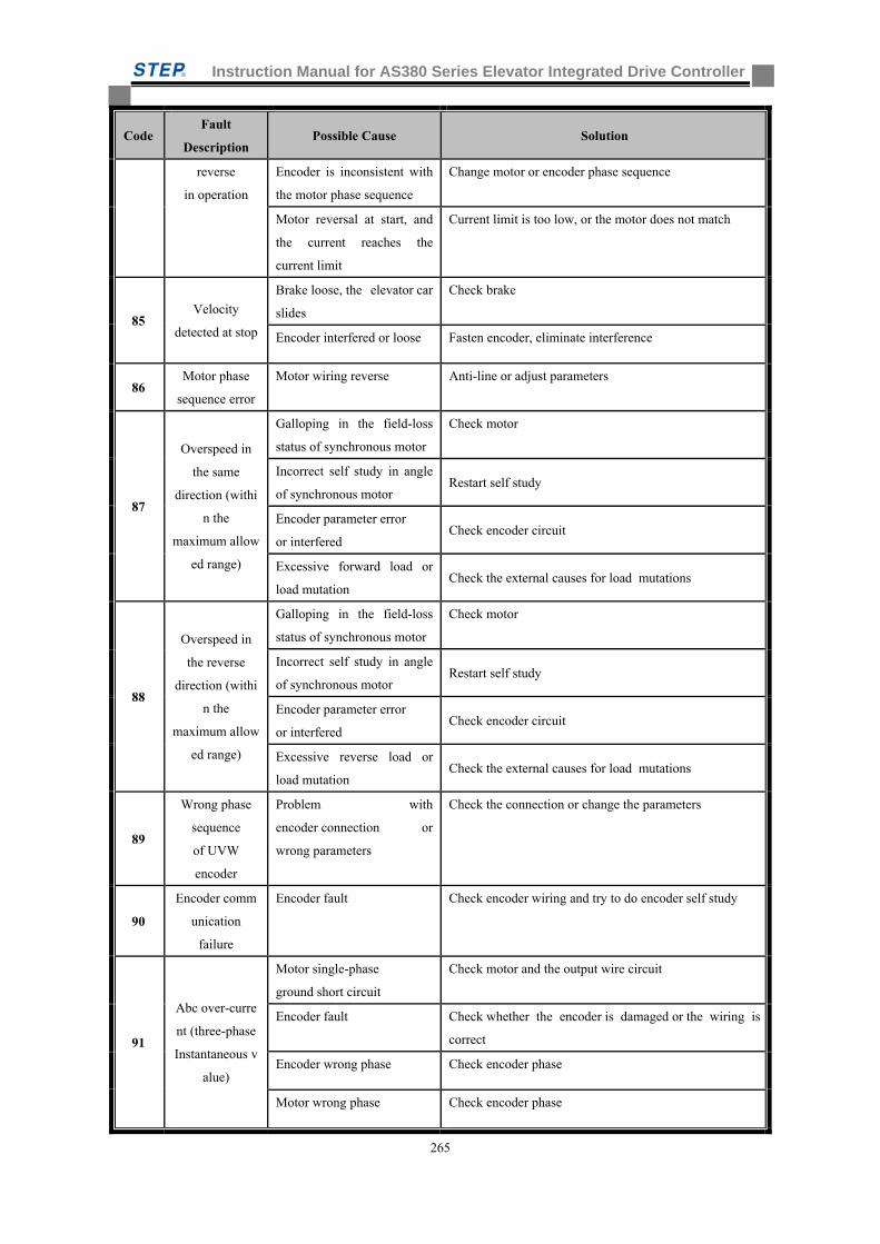
Instruction Manual for AS380 Series Elevator Integrated Drive Controller
265
Code Fault
Description Possible Cause Solution
reverse
in operation
Encoder is inconsistent with
the motor phase sequence
Change motor or encoder phase sequence
Motor reversal at start, and
the current reaches the
current limit
Current limit is too low, or the motor does not match
85 Velocity
detected at stop
Brake loose, the elevator car
slides
Check brake
Encoder interfered or loose Fasten encoder, eliminate interference
86 Motor phase
sequence error
Motor wiring reverse Anti-line or adjust parameters
87
Overspeed in
the same
direction (withi
n the
maximum allow
ed range)
Galloping in the field-loss
status of synchronous motor
Check motor
Incorrect self study in angle
of synchronous motor Restart self study
Encoder parameter error
or interfered Check encoder circuit
Excessive forward load or
load mutation Check the external causes for load mutations
88
Overspeed in
the reverse
direction (withi
n the
maximum allow
ed range)
Galloping in the field-loss
status of synchronous motor
Check motor
Incorrect self study in angle
of synchronous motor Restart self study
Encoder parameter error
or interfered Check encoder circuit
Excessive reverse load or
load mutation Check the external causes for load mutations
89
Wrong phase
sequence
of UVW
encoder
Problem with
encoder connection or
wrong parameters
Check the connection or change the parameters
90
Encoder comm
unication
failure
Encoder fault Check encoder wiring and try to do encoder self study
91
Abc over-curre
nt (three-phase
Instantaneous v
alue)
Motor single-phase
ground short circuit
Check motor and the output wire circuit
Encoder fault Check whether the encoder is damaged or the wiring is
correct
Encoder wrong phase Check encoder phase
Motor wrong phase Check encoder phase
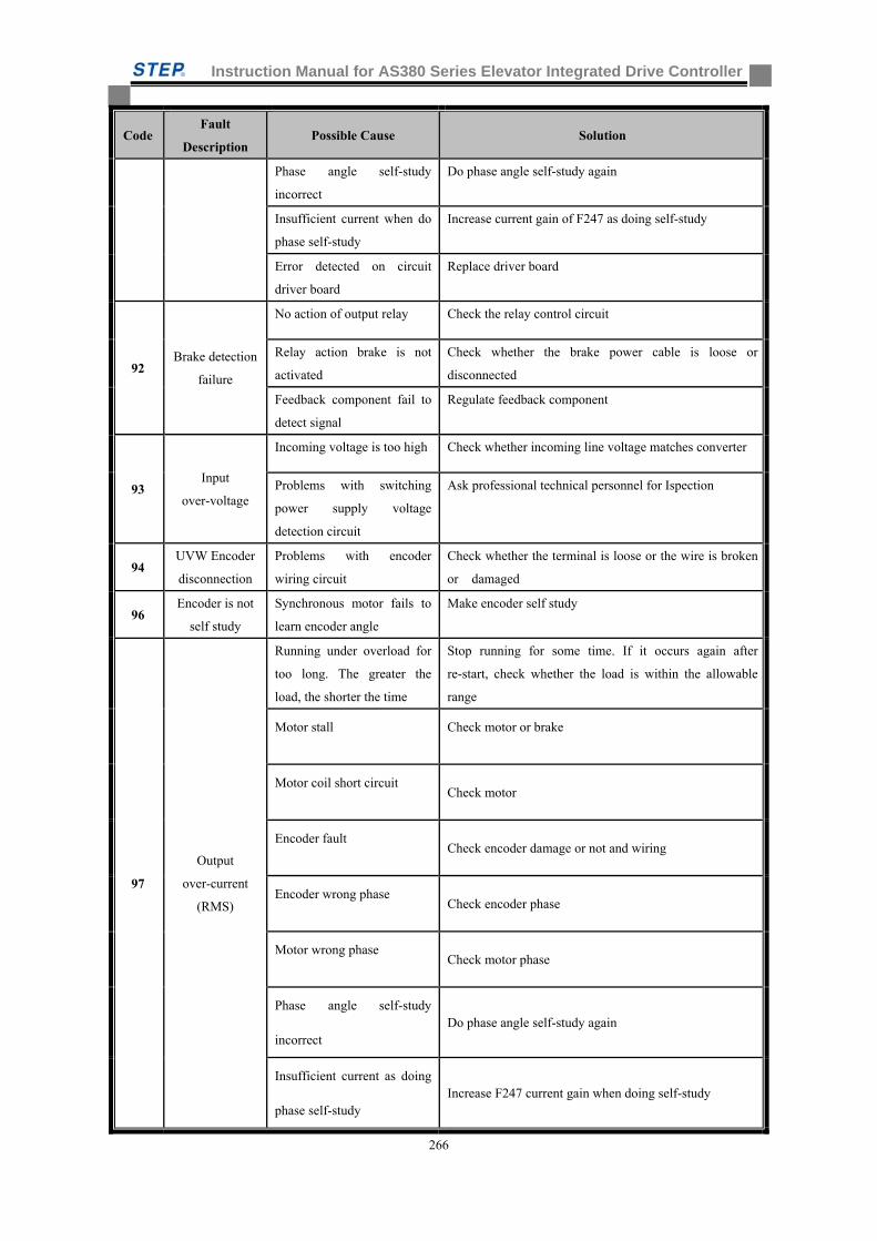
Instruction Manual for AS380 Series Elevator Integrated Drive Controller
266
Code Fault
Description Possible Cause Solution
Phase angle self-study
incorrect
Do phase angle self-study again
Insufficient current when do
phase self-study
Increase current gain of F247 as doing self-study
Error detected on circuit
driver board
Replace driver board
92 Brake detection
failure
No action of output relay Check the relay control circuit
Relay action brake is not
activated
Check whether the brake power cable is loose or
disconnected
Feedback component fail to
detect signal
Regulate feedback component
93 Input
over-voltage
Incoming voltage is too high Check whether incoming line voltage matches converter
Problems with switching
power supply voltage
detection circuit
Ask professional technical personnel for Ispection
94 UVW Encoder
disconnection
Problems with encoder
wiring circuit
Check whether the terminal is loose or the wire is broken
or damaged
96 Encoder is not
self study
Synchronous motor fails to
learn encoder angle
Make encoder self study
97
Output
over-current
(RMS)
Running under overload for
too long. The greater the
load, the shorter the time
Stop running for some time. If it occurs again after
re-start, check whether the load is within the allowable
range
Motor stall Check motor or brake
Motor coil short circuit Check motor
Encoder fault Check encoder damage or not and wiring
Encoder wrong phase Check encoder phase
Motor wrong phase Check motor phase
Phase angle self-study
incorrect Do phase angle self-study again
Insufficient current as doing
phase self-study Increase F247 current gain when doing self-study
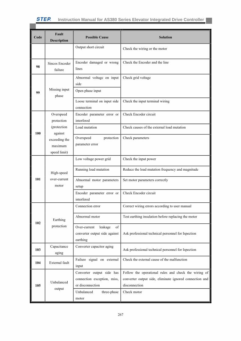
Instruction Manual for AS380 Series Elevator Integrated Drive Controller
267
Code Fault
Description Possible Cause Solution
Output short circuit Check the wiring or the motor
98 Sincos Encoder
failure
Encoder damaged or wrong
lines
Check the Encoder and the line
99 Missing input
phase
Abnormal voltage on input
side
Check grid voltage
Open phase input
Loose terminal on input side
connection
Check the input terminal wiring
100
Overspeed
protection
(protection
against
exceeding the
maximum
speed limit)
Encoder parameter error or
interfered
Check Encoder circuit
Load mutation Check causes of the external load mutation
Overspeed protection
parameter error
Check parameters
101
High-speed
over-current
motor
Low voltage power grid Check the input power
Running load mutation Reduce the load mutation frequency and magnitude
Abnormal motor parameters
setup
Set motor parameters correctly
Encoder parameter error or
interfered
Check Encoder circuit
102 Earthing
protection
Connection error Correct wiring errors according to user manual
Abnormal motor Test earthing insulation before replacing the motor
Over-current leakage of
converter output side against
earthing
Ask professional technical personnel for Ispection
103 Capacitance
aging
Converter capacitor aging Ask professional technical personnel for Ispection
104 External fault Failure signal on external
input
Check the external cause of the malfunction
105 Unbalanced
output
Converter output side has
connection exception, miss,
or disconnection
Follow the operational rules and check the wiring of
converter output side, eliminate ignored connection and
disconnection
Unbalanced three-phase
motor
Check motor
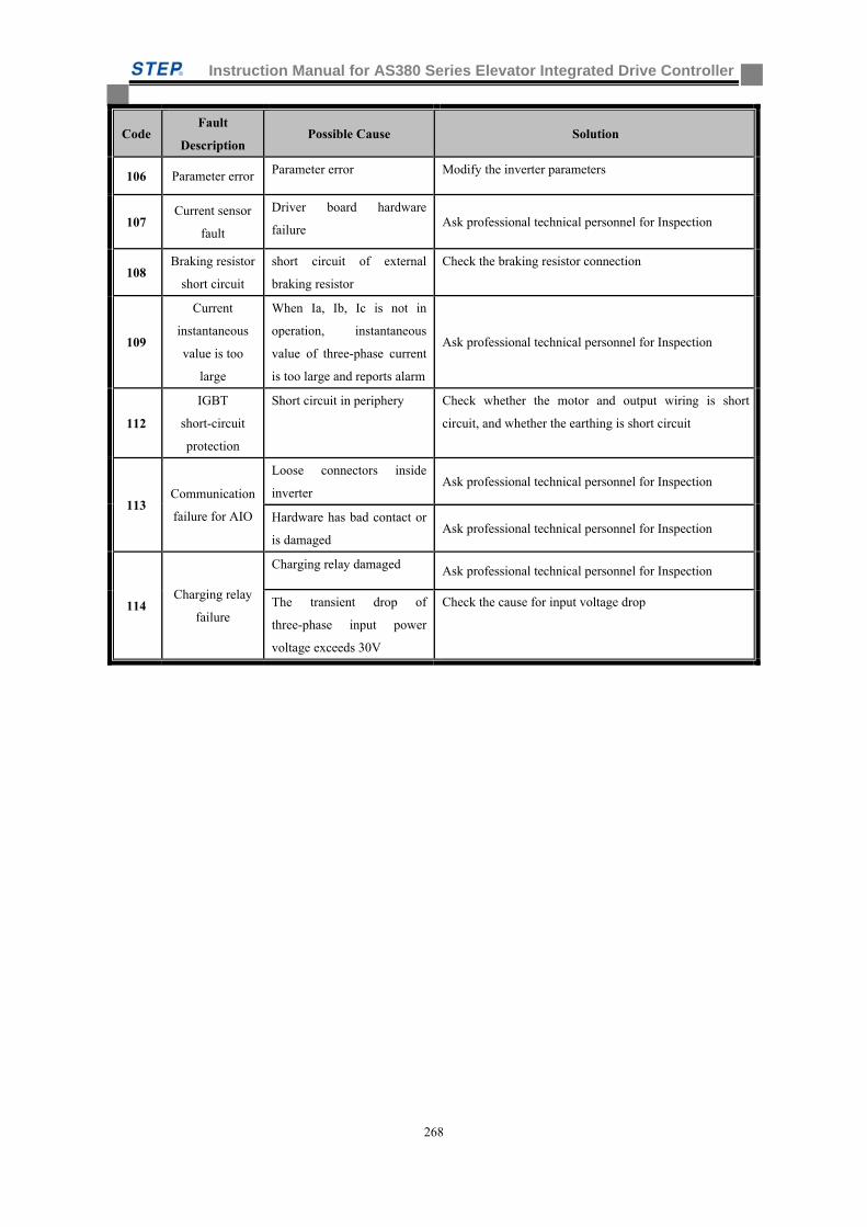
Instruction Manual for AS380 Series Elevator Integrated Drive Controller
268
Code Fault
Description Possible Cause Solution
106 Parameter error Parameter error Modify the inverter parameters
107 Current sensor
fault
Driver board hardware
failure Ask professional technical personnel for Inspection
108 Braking resistor
short circuit
short circuit of external
braking resistor
Check the braking resistor connection
109
Current
instantaneous
value is too
large
When Ia, Ib, Ic is not in
operation, instantaneous
value of three-phase current
is too large and reports alarm
Ask professional technical personnel for Inspection
112
IGBT
short-circuit
protection
Short circuit in periphery Check whether the motor and output wiring is short
circuit, and whether the earthing is short circuit
113 Communication
failure for AIO
Loose connectors inside
inverter Ask professional technical personnel for Inspection
Hardware has bad contact or
is damaged Ask professional technical personnel for Inspection
114 Charging relay
failure
Charging relay damaged Ask professional technical personnel for Inspection
The transient drop of
three-phase input power
voltage exceeds 30V
Check the cause for input voltage drop
Instruction Manual for AS380 Series Elevator Integrated Drive Controller
269
Appendix C Inverter complies with the standards
1. European Low Voltage directive
AS320 Series converter products complies with EN61800-5-1:2007 standards, which comply
with the Low Voltage Directive(Low Voltage Directive 2006/95/EC)。
The inverter also meet the following standards:
EN61800-5-1 : 2007:Adjustable speed electrical powerdrive systems –Part
5-1:Safetyrequirements –Electrical, thermal and energy
2. European EMC regulations
When you follow the recommendations in this manual for
installation, the AS320 seriesinverter product meets the following EMC standards:
EN12015.1998 Electromagnetic compatibility-Product family standard for lifts,
escalators and passenger conveyors-Emission.
EN12016.2004 Electromagnetic compatibility-Product family standard for lifts,
escalators and passenger conveyors-Immunity.
EN61800-3:2004: Power drive D of Part 3
3. ISO9001 Quality Management System
Shanghai Sigriner STEP Electric Co., Ltd will manage its quality management
system in accordance with the ISO9001 standards.
Instruction Manual for AS380 Series Elevator Integrated Drive Controller
270
Notice to customers
Dear customers:
RoHS is the English abbreviation of the Restriction of the use of certain hazardous substances in electrical and electronic equipment. EU implemented the RoHS on July 1, 2006, it regulates the limited use of six kinds of harmful materials during the electrical and electronic equipment products of recently putting on the market, such as lead, mercury, cadmium, sexavalence chromium, PBB, and PBDE etc..
On Feb 28, 2006, the seven ministries and commissions of Ministry of Information Industry of China, Development and Reform Commission, Department of Commerce, General Administration of Customs, State Administration for Industry and Commerce, State General Administration for Quality Supervision and Inspection and Quarantine, State Environmental Protection Administration jointly issued the Measures for Administration of the Pollution Control of Electronic Information Products which is the RoHS of Chinese version and make a compulsory implementation. On Feb 1, 2008, Measures for Administration of the Environmental Protection of Electronic Wastes Pollution which was issued by China Environmental Protection Administration began to be implemented which clearly regulated that the user of the electrical and electronic equipment product should offer or relegate the electronic waste to units (including individual business households) who had the corresponding scope of business listed in directory (including temporary directory) to demolish, utilize or dispose them.
The products of our company comply with the requirements of Measures for Administration of the Pollution Control of Electronic Information Products and RoHS on the part of electronic parts and components, PCB board, harness material, selecting and purchasing of structural element etc., it strictly controls the six kinds of harmful materials of lead, mercury, cadmium, sexavalence chromium, PBB, and PBDE. Also, during the production, PCB parts and components are welded in lead free product line using the lead free welding process.
The possible poisonous elements contained in the following components:
Components type Electronic component
Electronic printed
circuit board(PCB)
Sheet metal parts
Radiator Working of plastics
Wire
Possible poisonous elements
Six kinds of harmful materials of lead, mercury, cadmium, sexavalence chromium, PBB, and PBDE
1 Environmental impact analysis
During the usage, our company products will produce some heat to result in some harmful materials volatilizing very a little, however, it can not seriously affect the environment. While the electronic products are out of use at the end of the lifecycle and are discarded, the heavy metal and chemical poisonous material will seriously pollute the soil and water source.
2 Lifecycle of electronic products and equipments
Any electronic products and equipments have its service life and can be abandoned, even though it can be used, it also will be washed out by upgraded products. The lifecycle of our company electronic products and equipments are generally below 20 years.
3 Abandoned disposal methods of electronic products
Instruction Manual for AS380 Series Elevator Integrated Drive Controller
271
When the various electronic products are abandoned, if disposed improperly, they will pollute the environment. Our company requires the customer to establish the recycle system according to the national corresponding provisions, it can not be disposed as general domestic garbage or general industrial solid waste, and it shall be stored and utilized by environmental harmless method or unified recovered and disposed by authorized units strictly according to Measures for Administration of the Environmental Protection of Electronic Wastes Pollution issued by China Environmental Protection Administration. For any individual and unit without rights, to demolish, utilize or dispose electronic wastes is forbidden.
Please don’t discard the electronic wastes with common domestic garbage. Any proposal about disposal of electronic wastes, please contact local waste product disposal organization or environmental protection bureau.
Shanghai STEP Electric Corporation


![Voice outcomes post total laryngectomyeprints.leedsbeckett.ac.uk/3576/1/Voice Outcomes... · clinical use due to issues in providing consensus moduli [22]. However, the new finding](https://img.pdfslide.us/doc/110x75/5f534258870246510e5a9e69/voice-outcomes-post-total-outcomes-clinical-use-due-to-issues-in-providing.jpg)