Embed Size (px)
Citation preview
32
11. I/O CONFIGURATION AND END OF CYCLE FEEDBACK
During a spray cycle, an open collector circuit closes and remains closed while the valve is dispensing. Pin 3 and 4 can be as feedback signal to synchronize with other devices. Power from an external source is allowed to pass through the circuit to operate a 5 to 24 VDC load. Power consumption must not exceed 250 mA. The load could be a relay, solenoid, counter, LED, or any device that will operate within a 5 to 24 VDC range and a maximum of 250 mA.
Note: During the spray cycle, pin 3 will be grounded. Please make sure the external device (your machine that controls the controller) has the same ground as the controller.
7508-0260_A
Pin 7, 8, and 9 = Available
Chasis Ground
To initiate a dispense cycle with contact closure
When low pressure alarm is triggered, Pin 4 is grounded (-) When low pressure alarm is turned off, Pin 4 is not connected (opened)
End of Cycle Feedback During dispensing cycle, Pin 3 is grounded (-) End of dispensing cycle, Pin 3 is not connected (opened)
To initiate a dispense cycle with voltage Pin 1 (+)
Pin 2 (-)
Pin 3
Pin 4
Pin 5
Pin 6
Pin 5
TS560R SMART CONTROLLER FOR
SPRAY VALVES
User Guide
Copyright © OK International
2
CONTENTS Page Number
1. Safety ………………………………………………………………… 3
2. Symbol Definitions ……………………………………………….. 4
3. Specifications ……………………………………………….……….. 5
4. Features …………………………………………………………….. 5
5. To Control SprayValve…………………………………................. …. 6
5.1 Connecting the unit……..……………………………………… 6
5.1.1 Login …………………………………………………… 7
5.1.2 Pressure Calibration.…………………………………… . 7
5.2 Spraying ………………..……………………………............ 9
5.2.1 Pressure Adjustment ………………………………….. 9
5.2.2 To Change Pressure Unit Display …………..………... 9
5.2.3 Spray Time Setting ……………………………………... 10
5.2.4 Manual/Purge Cycle ……………………………………. 11
5.2.4 Automatic Cycle ……………………………………… 11
5.2.5 Teach Mode Setting …………………………………….. 12
5.2.6 To run in Continuous mode …………………………….. 12
5.3 Low Pressure Alarm Setting ……………………………….. 14
5.4 Stored Program in Memory Cell …………………………….. 15
5.4.1 To store dispense parameters …………………………… 15
5.4.2 To run in Single Sequence mode ……………………….. 15
5.4.3 To run in Continous Sequence mode …………………… 17
5.5 Cycle Counter ………………………………………………... 17
5.6 To Change Password ………………………………………….. 18
5.7 To Connect to Wi-Fi network ………………………………… 20
6. Internet of Thing (IoT) ………………………………………………... 22
7. Software Upgrade …………………………………………………….. 28
8. Troubleshooting …………………………………………………….. 30
9. Maintenance …………………………………………………………. 31
10. Warranty ……………………………………………………………... 31
11. I/O Configuration and End of Cycle Switch ………………………. 32
31
9. MAINTENANCE
The controller is designed and built to be relatively maintenance free. To assure trouble free operation, please follow below steps:
1. Make certain air supply is clean and dry. 2. Avoid connecting the unit to excessive moisture or solvent saturation 3. Avoid connecting air supply exceeding 100 psi (6.9 bars) 4. Use only Amyl Alcohol to clean outside surface of the main housing 5. Use only soft cloth to clean the display screen
10. LIMITED WARRANTY OK International warrants this product to the original purchaser for a period of 2 years from date of purchase to be free from material and workmanship defects but not normal wear-and-tear, abuse and faulty installation. Defective product or subassembly and components under warranty will be repaired or replaced (at OK International's option) free of charge. Customer with defective product under warranty must contact the nearest OK International office or distributor to secure a return authorization prior to shipping the product to the assigned OK International authorized service center. For nearest OK International office or distributor contact information, please visit www.techconsystems.com. OK International reserves the right to make engineering product changes without notice.
All returns must be issued with a Returns Authorization number, prior to return. Send warranty returns to:
Americas OK International
10800 Valley View Street Cypress, CA 90630 +1 714 230 2398
Europe OK International Eagle Close Chandler’s Ford Ind Est Eastleigh, Hampshire SO53 4NF United Kingdom +44 2380 489 100
Asia Dover (Shenzhen) Industrial Equipment Manufacturing Co., LTD. 4th Floor East, Electronic Building Yanxiang Industrial Zone, High Tech Road Guangmin New District Shenzhen, P.R.C +86 21 64952662
www.techconsystems.com
30
8. TROUBLESHOOTING
PROBLEM POSSIBLE CAUSE CORRECTIONDisplay does not light up
No power inputs
Check power cord connections
Turn on power
System will not actuate
Supplied pressure dropped below “Low Pressure” setting
Foot switch not plugged in or improperly plugged in
Defective foot switch Broken wire or loose
connection inside unit
Defective solenoid Defective PC board
Increase supplied pressure
Check foot switch
connection Foot switch needs to be
repaired or replaced Unplug power cord and
disconnect air supply. Remove cover and check for broken wires or loose connections
Replace solenoid Replace PC board
System will not pressurize
Insufficient air pressure Air hoses not plugged
in Regulator defective
Increase air supply pressure
Check connection Replace regulator
Inconsistent spray coverage
Air bubbles in material Activation time is too
low
De-air material Increase activation time
3
1. SAFETY
1.1 Intended Use: WARNING: Use of this equipment in ways other than those described in this User Guide may result in injury to persons or damage to property. Use this equipment only as described in this User Guide. OK International cannot be responsible for injuries or damages resulting from unintended applications of its equipment. Unintended uses may result form taking the following actions: Making changes to equipment that has not been recommended in the User
Guide Using incompatible or damaged replacement parts Using unapproved accessories or auxiliary equipment
1.2 Safety Precautions: Do not operate this unit in excess of maximum ratings/settings Always wear appropriate personal protective clothing or apparel The fluid may be toxic and/or hazardous. Refer to Material Safety Data Sheet
for proper handling and safety precautions Do not smoke or use open flame when flammable materials are being sprayed This equipment is for indoor use only
4
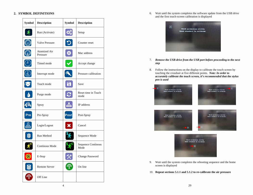
2. SYMBOL DEFINITIONS
Symbol Description Symbol Description
Run (Activate)
Setup
Valve Pressure
Counter reset
Atomized Air Pressure
Mac address
Timed mode
Accept change
Interrupt mode
Pressure calibration
Teach mode
Save
Purge mode
Reset time in Teach mode
Spray
IP address
Pre-Spray
Post-Spray
Login/Logout
Cancel
Run Method
Sequence Mode
Continous Mode
Sequence Continous Mode
E-Stop
Change Password
Remote Server
On line
Off Line
29
6. Wait until the system completes the software update from the USB drive and the first touch-screen calibration is displayed
7. Remove the USB drive from the USB port before proceeding to the next step
8. Follow the instructions on the display to calibrate the touch screen by touching the crosshair at five different points. Note: In order to accurately calibrate the touch screen, it’s recommended that the stylus pen is used
9. Wait until the system completes the rebooting sequence and the home screen is displayed
10. Repeat sections 5.1.1 and 5.1.2 to re-calibrate the air pressure
28
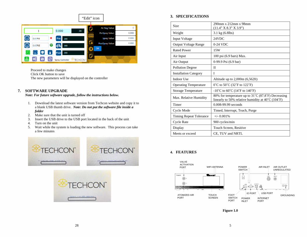
Proceed to make changes Click OK button to save The new parameters will be displayed on the controller 7. SOFTWARE UPGRADE
Note: For future software upgrade, follow the instructions below.
1. Download the latest software version from Techcon website and copy it to a blank USB thumb drive. Note: Do not put the software file inside a folder
2. Make sure that the unit is turned off 3. Insert the USB drive to the USB port located in the back of the unit 4. Turn on the unit 5. Wait while the system is loading the new software. This process can take
a few minutes
“Edit” icon
5
TOUCHSCREEN
ATOMIZED AIRPORT
VALVEACTIVATIONPORT WIFI ANTENNA POWER
SWITCHAIR INLET AIR OUTLET
UNREGULATED
FOOTSWITCHPORT
POWERINLET
IO PORT
INTERNETPORT
USB PORTGROUNDING
TS560R
3. SPECIFICATIONS
4. FEATURES
Figure 1.0
Size 290mm x 212mm x 98mm (11.4” X 8.3” X 3.9”)
Weight 3.1 kg (6.8lbs)
Input Voltage 24VDC
Output Voltage Range 0-24 VDC
Rated Power 15W
Air Input 100 psi (6.9 bars) Max.
Air Output 0-99.9 Psi (6.9 bar)
Pollution Degree II
Installation Category I
Indoor Use Altitude up to 2,000m (6,562ft)
Operating Temperature 0˚C to 50˚C (32˚F to 122˚F)
Storage Temperature -10˚C to 60˚C (14˚F to 140˚F)
Max. Relative Humidity 80% for temperature up to 31˚C (87.8˚F) Decreasing linearly to 50% relative humidity at 40˚C (104˚F)
Timer 0.008-99.99 seconds
Cycle Mode Timed, Interrupt, Teach, Purge
Timing Repeat Tolerance +/- 0.001%
Cycle Rate 900 cycles/min
Display Touch Screen, Resitive
Meets or exceed CE, TUV and NRTL
6
TS560R
1
5
2
3
6
4
VALVE AIR HOSE
ATOMIZED AIR HOSE
TO AIR SOURCE
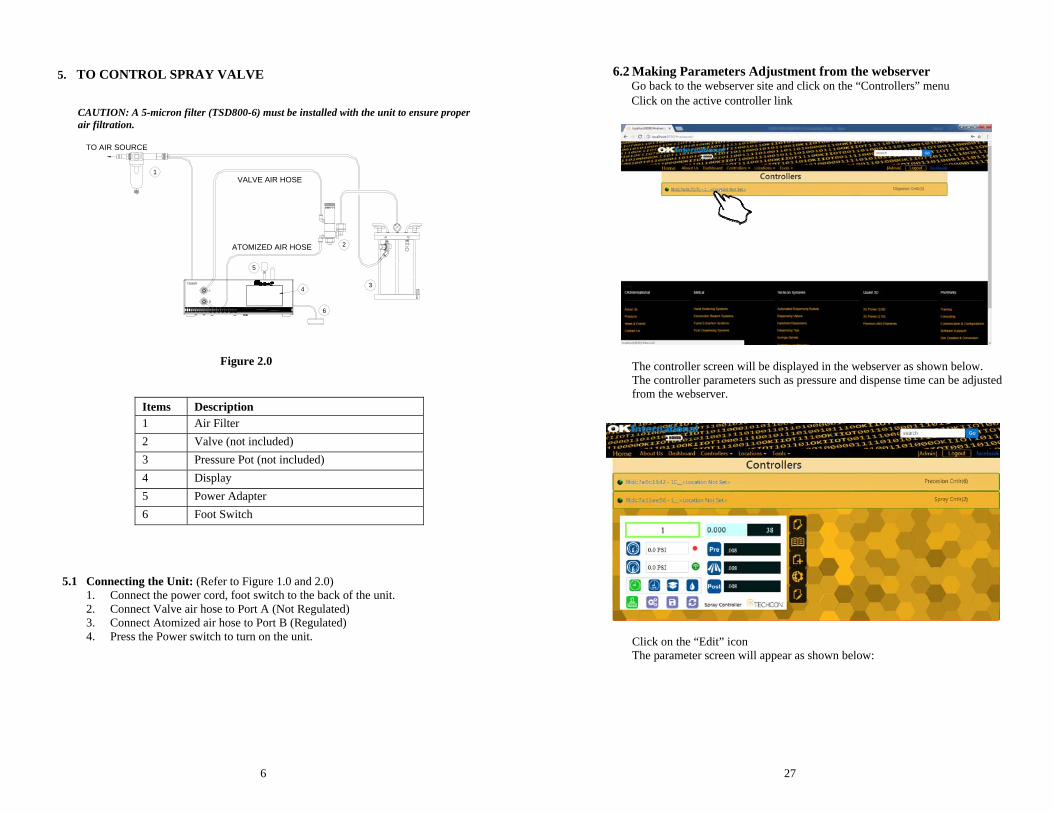
5. TO CONTROL SPRAY VALVE
CAUTION: A 5-micron filter (TSD800-6) must be installed with the unit to ensure proper air filtration.
Figure 2.0
5.1 Connecting the Unit: (Refer to Figure 1.0 and 2.0) 1. Connect the power cord, foot switch to the back of the unit. 2. Connect Valve air hose to Port A (Not Regulated) 3. Connect Atomized air hose to Port B (Regulated) 4. Press the Power switch to turn on the unit.
Items Description 1 Air Filter 2 Valve (not included) 3 Pressure Pot (not included) 4 Display 5 Power Adapter 6 Foot Switch
27
6.2 Making Parameters Adjustment from the webserver
Go back to the webserver site and click on the “Controllers” menu Click on the active controller link
The controller screen will be displayed in the webserver as shown below. The controller parameters such as pressure and dispense time can be adjusted from the webserver.
Click on the “Edit” icon The parameter screen will appear as shown below:
26
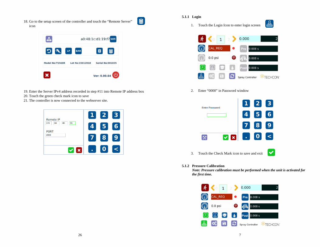
18. Go to the setup screen of the controller and touch the “Remote Server”
icon
19. Enter the Server IPv4 address recorded in step #11 into Remote IP address box 20. Touch the green check mark icon to save 21. The controller is now connected to the webserver site.
7
5.1.1 Login
1. Touch the Login Icon to enter login screen
2. Enter “0000” in Password window
3. Touch the Check Mark icon to save and exit
5.1.2 Pressure Calibration Note: Pressure calibration must be performed when the unit is activated for the first time.
8
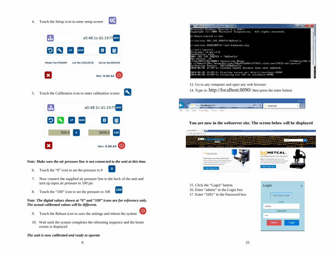
4. Touch the Setup icon to enter setup screen
5. Touch the Calibration icon to enter calibration screen
Note: Make sure the air pressure line is not connected to the unit at this time.
6. Touch the “0” icon to set the pressure to 0
7. Now connect the supplied air pressure line to the back of the unit and turn up input air pressure to 100 psi
8. Touch the “100” icon to set the pressure to 100
Note: The digital values shown at “0” and “100” icons are for reference only. The actual calibrated values will be different.
9. Touch the Reboot icon to save the settings and reboot the system
10. Wait until the system completes the rebooting sequence and the home screen is displayed
The unit is now calibrated and ready to operate
25
13. Go to any computer and open any web browser 14. Type in: http://localhost:8090/ then press the enter button
You are now in the webserver site. The screen below will be displayed
15. Click the “Login” button 16. Enter “admin” in the Login box 17. Enter “1001” in the Password box
24
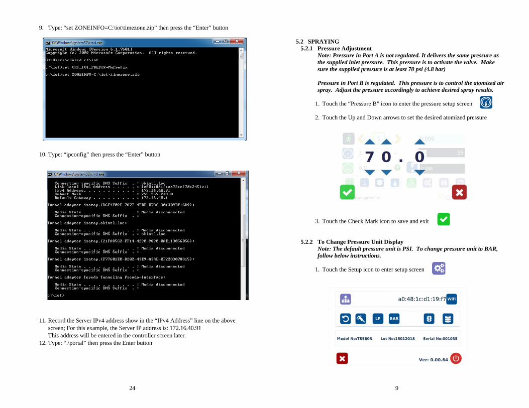
9. Type: “set ZONEINFO=C:\iot\timezone.zip” then press the “Enter” button
10. Type: “ipconfig” then press the “Enter” button
11. Record the Server IPv4 address show in the “IPv4 Address” line on the above
screen; For this example, the Server IP address is: 172.16.40.91 This address will be entered in the controller screen later.
12. Type: “.\portal” then press the Enter button
9
5.2 SPRAYING 5.2.1 Pressure Adjustment
Note: Pressure in Port A is not regulated. It delivers the same pressure as the supplied inlet pressure. This pressure is to activate the valve. Make sure the supplied pressure is at least 70 psi (4.8 bar) Pressure in Port B is regulated. This pressure is to control the atomized air spray. Adjust the pressure accordingly to achieve desired spray results.
1. Touch the “Pressure B” icon to enter the pressure setup screen
2. Touch the Up and Down arrows to set the desired atomized pressure
3. Touch the Check Mark icon to save and exit
5.2.2 To Change Pressure Unit Display Note: The default pressure unit is PSI. To change pressure unit to BAR, follow below instructions.
1. Touch the Setup icon to enter setup screen
10
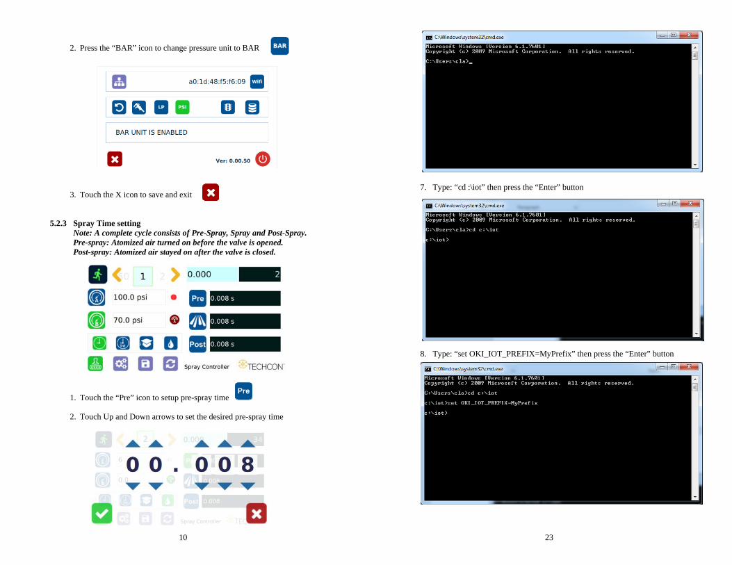
2. Press the “BAR” icon to change pressure unit to BAR
3. Touch the X icon to save and exit
5.2.3 Spray Time setting Note: A complete cycle consists of Pre-Spray, Spray and Post-Spray. Pre-spray: Atomized air turned on before the valve is opened. Post-spray: Atomized air stayed on after the valve is closed.
1. Touch the “Pre” icon to setup pre-spray time
2. Touch Up and Down arrows to set the desired pre-spray time
23
7. Type: “cd :\iot” then press the “Enter” button
8. Type: “set OKI_IOT_PREFIX=MyPrefix” then press the “Enter” button
22
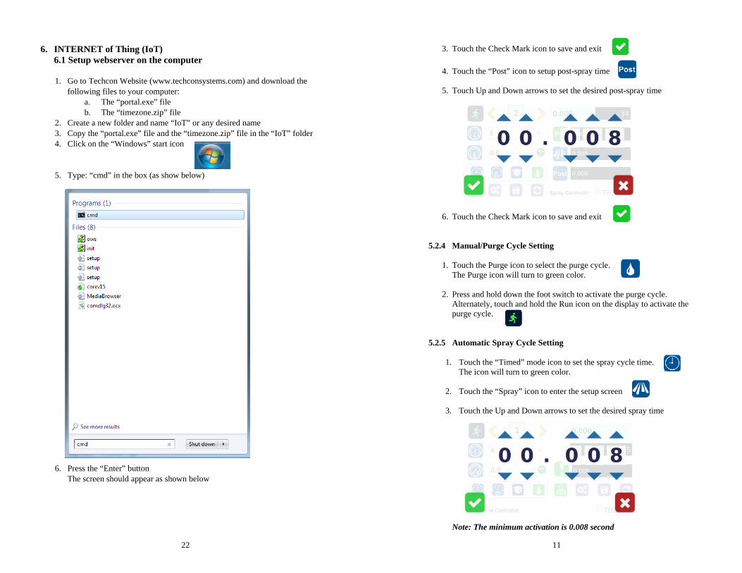
6. INTERNET of Thing (IoT)
6.1 Setup webserver on the computer 1. Go to Techcon Website (www.techconsystems.com) and download the
following files to your computer: a. The “portal.exe” file b. The “timezone.zip” file
2. Create a new folder and name “IoT” or any desired name 3. Copy the “portal.exe” file and the “timezone.zip” file in the “IoT” folder 4. Click on the “Windows” start icon
5. Type: “cmd” in the box (as show below)
6. Press the “Enter” button The screen should appear as shown below
11
3. Touch the Check Mark icon to save and exit
4. Touch the “Post” icon to setup post-spray time
5. Touch Up and Down arrows to set the desired post-spray time
6. Touch the Check Mark icon to save and exit
5.2.4 Manual/Purge Cycle Setting
1. Touch the Purge icon to select the purge cycle. The Purge icon will turn to green color.
2. Press and hold down the foot switch to activate the purge cycle. Alternately, touch and hold the Run icon on the display to activate the purge cycle.
5.2.5 Automatic Spray Cycle Setting
1. Touch the “Timed” mode icon to set the spray cycle time. The icon will turn to green color.
2. Touch the “Spray” icon to enter the setup screen
3. Touch the Up and Down arrows to set the desired spray time
Note: The minimum activation is 0.008 second
12
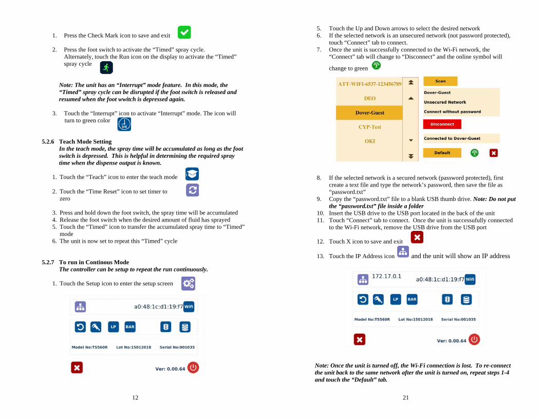
1. Press the Check Mark icon to save and exit
2. Press the foot switch to activate the “Timed” spray cycle.
Alternately, touch the Run icon on the display to activate the “Timed” spray cycle
Note: The unit has an “Interrupt” mode feature. In this mode, the “Timed” spray cycle can be disrupted if the foot switch is released and resumed when the foot wwitch is depressed again.
3. Touch the “Interrupt” icon to activate “Interrupt” mode. The icon will turn to green color
5.2.6 Teach Mode Setting In the teach mode, the spray time will be accumulated as long as the foot switch is depressed. This is helpful in determining the required spray time when the dispense output is known.
1. Touch the “Teach” icon to enter the teach mode
2. Touch the “Time Reset” icon to set timer to zero
3. Press and hold down the foot switch, the spray time will be accumulated 4. Release the foot switch when the desired amount of fluid has sprayed 5. Touch the “Timed” icon to transfer the accumulated spray time to “Timed”
mode 6. The unit is now set to repeat this “Timed” cycle
5.2.7 To run in Continous Mode The controller can be setup to repeat the run continuously.
1. Touch the Setup icon to enter the setup screen
21
5. Touch the Up and Down arrows to select the desired network 6. If the selected network is an unsecured network (not password protected),
touch “Connect” tab to connect. 7. Once the unit is successfully connected to the Wi-Fi network, the
“Connect” tab will change to “Disconnect” and the online symbol will
change to green
8. If the selected network is a secured network (password protected), first create a text file and type the network’s password, then save the file as “password.txt”
9. Copy the “password.txt” file to a blank USB thumb drive. Note: Do not put the “password.txt” file inside a folder
10. Insert the USB drive to the USB port located in the back of the unit 11. Touch “Connect” tab to connect. Once the unit is successufully connected
to the Wi-Fi network, remove the USB drive from the USB port
12. Touch X icon to save and exit
13. Touch the IP Address icon and the unit will show an IP address
Note: Once the unit is turned off, the Wi-Fi connection is lost. To re-connect the unit back to the same network after the unit is turned on, repeat steps 1-4 and touch the “Default” tab.
20
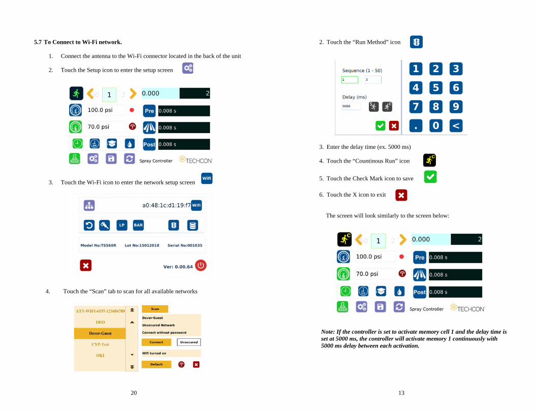
5.7 To Connect to Wi-Fi network.
1. Connect the antenna to the Wi-Fi connector located in the back of the unit
2. Touch the Setup icon to enter the setup screen
3. Touch the Wi-Fi icon to enter the network setup screen
4. Touch the “Scan” tab to scan for all available networks
13
2. Touch the “Run Method” icon
3. Enter the delay time (ex. 5000 ms)
4. Touch the “Countinous Run” icon
5. Touch the Check Mark icon to save
6. Touch the X icon to exit
The screen will look similarly to the screen below:
Note: If the controller is set to activate memory cell 1 and the delay time is set at 5000 ms, the controller will activate memory 1 continuously with 5000 ms delay between each activation.
14
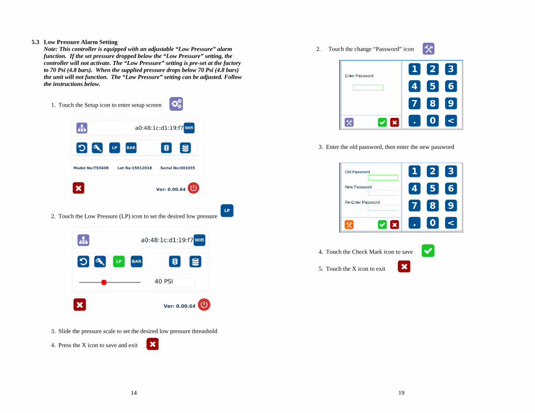
5.3 Low Pressure Alarm Setting Note: This controller is equipped with an adjustable “Low Pressure” alarm function. If the set pressure dropped below the “Low Pressure” setting, the controller will not activate. The “Low Pressure” setting is pre-set at the factory to 70 Psi (4.8 bars). When the supplied pressure drops below 70 Psi (4.8 bars) the unit will not function. The “Low Pressure” setting can be adjusted. Follow the instructions below.
1. Touch the Setup icon to enter setup screen
2. Touch the Low Pressure (LP) icon to set the desired low pressure
3. Slide the pressure scale to set the desired low pressure threashold
4. Press the X icon to save and exit
19
2. Touch the change “Password” icon
3. Enter the old password, then enter the new password
4. Touch the Check Mark icon to save
5. Touch the X icon to exit
18
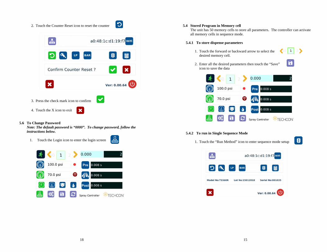
2. Touch the Counter Reset icon to reset the counter
3. Press the check mark icon to confirm
4. Touch the X icon to exit
5.6 To Change Password
Note: The default password is “0000”. To change password, follow the instructions below.
1. Touch the Login icon to enter the login screen
15
5.4 Stored Program in Memory cell The unit has 50 memory cells to store all parameters. The controller can activate all memory cells in sequence mode.
5.4.1 To store dispense parameters
1. Touch the forward or backward arrow to select the desired memory cell.
2. Enter all the desired parameters then touch the “Save” icon to save the data
5.4.2 To run in Single Sequence Mode
1. Touch the “Run Method” icon to enter sequence mode setup
16
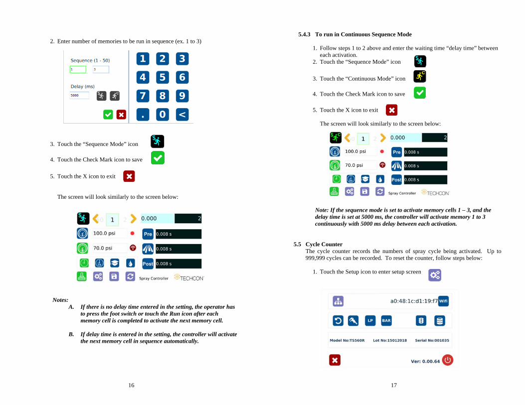
2. Enter number of memories to be run in sequence (ex. 1 to 3)
3. Touch the “Sequence Mode” icon
4. Touch the Check Mark icon to save
5. Touch the X icon to exit
The screen will look similarly to the screen below:
Notes:
A. If there is no delay time entered in the setting, the operator has to press the foot switch or touch the Run icon after each memory cell is completed to activate the next memory cell.
B. If delay time is entered in the setting, the controller will activate the next memory cell in sequence automatically.
17
5.4.3 To run in Continuous Sequence Mode
1. Follow steps 1 to 2 above and enter the waiting time “delay time” between
each activation. 2. Touch the “Sequence Mode” icon
3. Touch the “Continuous Mode” icon
4. Touch the Check Mark icon to save
5. Touch the X icon to exit
The screen will look similarly to the screen below:
Note: If the sequence mode is set to activate memory cells 1 – 3, and the delay time is set at 5000 ms, the controller will activate memory 1 to 3 continuously with 5000 ms delay between each activation.
5.5 Cycle Counter The cycle counter records the numbers of spray cycle being activated. Up to 999,999 cycles can be recorded. To reset the counter, follow steps below:
1. Touch the Setup icon to enter setup screen