Embed Size (px)
Citation preview
Zelio Control
EIO0000001300 09/2012
EIO
0000
0013
00.0
0
www.schneider-electric.com
Zelio ControlREG24 Temperature ControllerUser Guide
09/2012
Schneider Electric assumes no responsibility for any errors that may appear in this document. If you have any suggestions for improvements or amendments or have found errors in this publication, please notify us.
No part of this document may be reproduced in any form or by any means, electronic or mechanical, including photocopying, without express written permission of Schneider Electric.
All pertinent state, regional, and local safety regulations must be observed when installing and using this product. For reasons of safety and to help ensure compliance with documented system data, only the manufacturer should perform repairs to components.
When devices are used for applications with technical safety requirements, the relevant instructions must be followed.
Failure to use Schneider Electric software or approved software with our hardware products may result in injury, harm, or improper operating results.
Failure to observe this information can result in injury or equipment damage.
© 2012 Schneider Electric. All rights reserved.
2 EIO0000001300 09/2012
Table of Contents
Safety Information . . . . . . . . . . . . . . . . . . . . . . . . . . . . . . 5About the Book . . . . . . . . . . . . . . . . . . . . . . . . . . . . . . . . . 7
Part I REG24 Temperature Controller. . . . . . . . . . . . . . . . . 9Chapter 1 Introduction. . . . . . . . . . . . . . . . . . . . . . . . . . . . . . . . . . . . 11
Display and Controller References of REG24. . . . . . . . . . . . . . . . . . . . . . 12Main Characteristics . . . . . . . . . . . . . . . . . . . . . . . . . . . . . . . . . . . . . . . . . 15
Chapter 2 Hardware of REG24 . . . . . . . . . . . . . . . . . . . . . . . . . . . . . 17Electrical and Environmental Characteristics . . . . . . . . . . . . . . . . . . . . . . 18Dimensions and Installation of REG24 . . . . . . . . . . . . . . . . . . . . . . . . . . . 20Wiring of REG24 . . . . . . . . . . . . . . . . . . . . . . . . . . . . . . . . . . . . . . . . . . . . 27
Chapter 3 Configuration of REG24 . . . . . . . . . . . . . . . . . . . . . . . . . . 31How to Configure Using Front panel . . . . . . . . . . . . . . . . . . . . . . . . . . . . . 32Basic Operations . . . . . . . . . . . . . . . . . . . . . . . . . . . . . . . . . . . . . . . . . . . . 33Key Lock . . . . . . . . . . . . . . . . . . . . . . . . . . . . . . . . . . . . . . . . . . . . . . . . . . 35Setting the Temperature Controller . . . . . . . . . . . . . . . . . . . . . . . . . . . . . . 37Parameters List . . . . . . . . . . . . . . . . . . . . . . . . . . . . . . . . . . . . . . . . . . . . . 41
Chapter 4 Main Functions of REG24 . . . . . . . . . . . . . . . . . . . . . . . . 47ON/OFF Control . . . . . . . . . . . . . . . . . . . . . . . . . . . . . . . . . . . . . . . . . . . . 48Auto-tuning . . . . . . . . . . . . . . . . . . . . . . . . . . . . . . . . . . . . . . . . . . . . . . . . 50Self-Tuning . . . . . . . . . . . . . . . . . . . . . . . . . . . . . . . . . . . . . . . . . . . . . . . . 53Alarm Function . . . . . . . . . . . . . . . . . . . . . . . . . . . . . . . . . . . . . . . . . . . . . 55Ramp/Soak . . . . . . . . . . . . . . . . . . . . . . . . . . . . . . . . . . . . . . . . . . . . . . . . 63Other Function: Anti-reset windup (Ar) and Output Convergence Value (bAL) . . . . . . . . . . . . . . . . . . . . . . . . . . . . . . . . . . . . . . . . . . . . . . . . . . . . . 67
Part II Appendices . . . . . . . . . . . . . . . . . . . . . . . . . . . . . . . . . 69Chapter 5 REG24 Error Message . . . . . . . . . . . . . . . . . . . . . . . . . . . 71
Error Indications . . . . . . . . . . . . . . . . . . . . . . . . . . . . . . . . . . . . . . . . . . . . 71
Index . . . . . . . . . . . . . . . . . . . . . . . . . . . . . . . . . . . . . . . . . . . 73
EIO0000001300 09/2012 3

4 EIO0000001300 09/2012
§
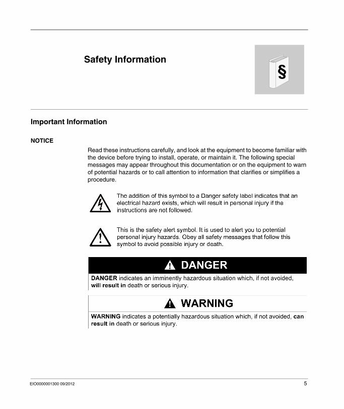
Safety InformationImportant Information
NOTICE
Read these instructions carefully, and look at the equipment to become familiar with the device before trying to install, operate, or maintain it. The following special messages may appear throughout this documentation or on the equipment to warn of potential hazards or to call attention to information that clarifies or simplifies a procedure.
EIO0000001300 09/2012 5
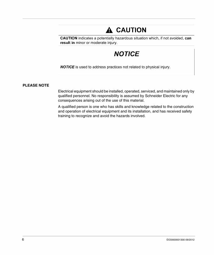
PLEASE NOTE
Electrical equipment should be installed, operated, serviced, and maintained only by qualified personnel. No responsibility is assumed by Schneider Electric for any consequences arising out of the use of this material.
A qualified person is one who has skills and knowledge related to the construction and operation of electrical equipment and its installation, and has received safety training to recognize and avoid the hazards involved.
6 EIO0000001300 09/2012
About the Book
At a Glance
Document Scope
This manual will acquaint you with the Temperature Controller REG24 tell you how to install them, describe changes you may make in configuration, review the operation.
The Temperature Controller is Single loop controller controlled devices performing the following enhanced functions:
PIDAuto-tuningFuzzy logicAlarmsRamps
There are 3 versions of Temperature Controllers, with different sizes and characteristics.
The product references in accordance with the sizes are:REG24P••••••: 24x48 mm (0.94x1.89 in.)REG48P••••••: 48x48 mm (1.89x1.89 in.) (Refer to Zelio Control, REG48/96 Temperature Controller User Guide (see Zelio Control, REG48/96 Temperature Controller, User Guide))REG96P••••••: 48x96 mm (1.89x3.78 in.) Refer to Zelio Control, REG48/96 Temperature Controller User Guide (see Zelio Control, REG48/96 Temperature Controller, User Guide))
Solution approach used:ControllersSensorsSolid state and electromechanical relays
EIO0000001300 09/2012 7
Validity Note
This document is valid for Temperature Controllers REG24
Registered Trademarks
Microsoft® and Windows® are registered trademarks of Microsoft Corporation.
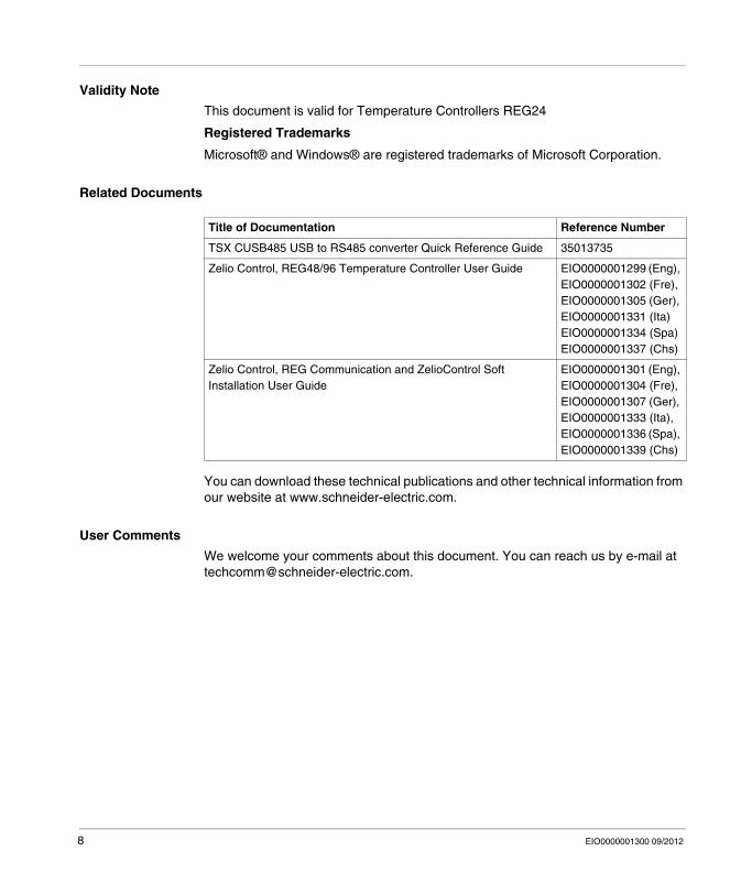
Related Documents
You can download these technical publications and other technical information from our website at www.schneider-electric.com.
User Comments
We welcome your comments about this document. You can reach us by e-mail at [email protected].
Title of Documentation Reference Number
TSX CUSB485 USB to RS485 converter Quick Reference Guide 35013735
Zelio Control, REG48/96 Temperature Controller User Guide EIO0000001299 (Eng), EIO0000001302 (Fre), EIO0000001305 (Ger), EIO0000001331 (Ita) EIO0000001334 (Spa) EIO0000001337 (Chs)
Zelio Control, REG Communication and ZelioControl Soft Installation User Guide
EIO0000001301 (Eng), EIO0000001304 (Fre), EIO0000001307 (Ger), EIO0000001333 (Ita), EIO0000001336 (Spa), EIO0000001339 (Chs)
8 EIO0000001300 09/2012
EIO0000001300 09/2012
I
Zelio Control
REG24 Temperature Controller
EIO0000001300 09/2012
REG24 Temperature Controller
What Is in This Part?
This part contains the following chapters:
Chapter Chapter Name Page
1 Introduction 11
2 Hardware of REG24 17
3 Configuration of REG24 31
4 Main Functions of REG24 47
9

REG24 Temperature Controller
10 EIO0000001300 09/2012
EIO0000001300 09/2012
1
Zelio Control
Introduction
EIO0000001300 09/2012
Introduction
What Is in This Chapter?
This chapter contains the following topics:
Topic Page
Display and Controller References of REG24 12
Main Characteristics 15
11
Introduction
Display and Controller References of REG24
Overview
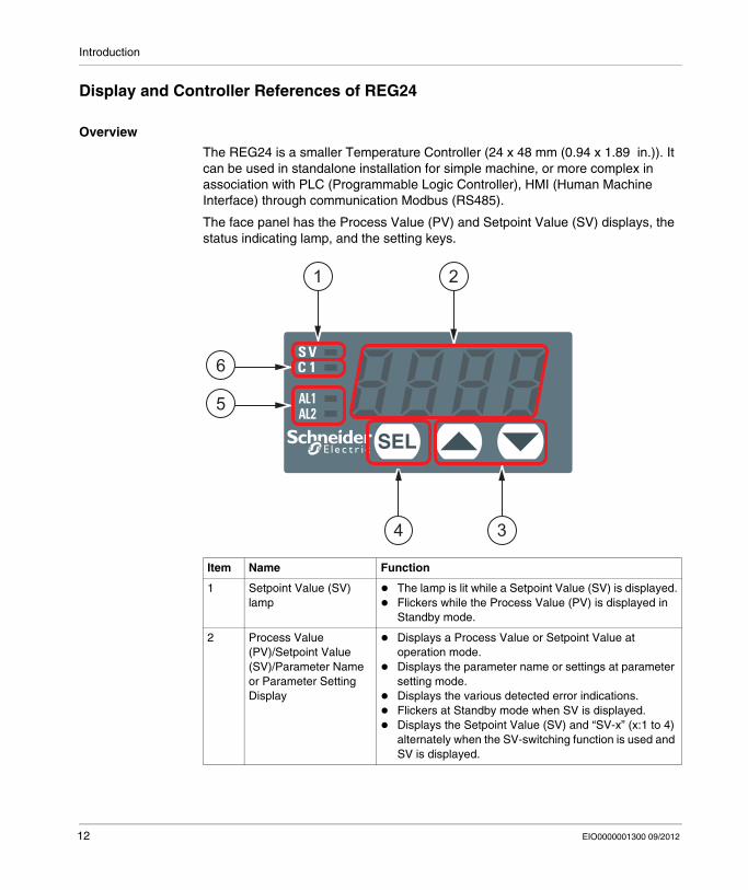
The REG24 is a smaller Temperature Controller (24 x 48 mm (0.94 x 1.89 in.)). It can be used in standalone installation for simple machine, or more complex in association with PLC (Programmable Logic Controller), HMI (Human Machine Interface) through communication Modbus (RS485).
The face panel has the Process Value (PV) and Setpoint Value (SV) displays, the status indicating lamp, and the setting keys.
Item Name Function
1 Setpoint Value (SV) lamp
The lamp is lit while a Setpoint Value (SV) is displayed.Flickers while the Process Value (PV) is displayed in Standby mode.
2 Process Value (PV)/Setpoint Value (SV)/Parameter Name or Parameter Setting Display
Displays a Process Value or Setpoint Value at operation mode.Displays the parameter name or settings at parameter setting mode.Displays the various detected error indications.Flickers at Standby mode when SV is displayed.Displays the Setpoint Value (SV) and “SV-x” (x:1 to 4) alternately when the SV-switching function is used and SV is displayed.
1 2
34
5
6
12 EIO0000001300 09/2012
Introduction
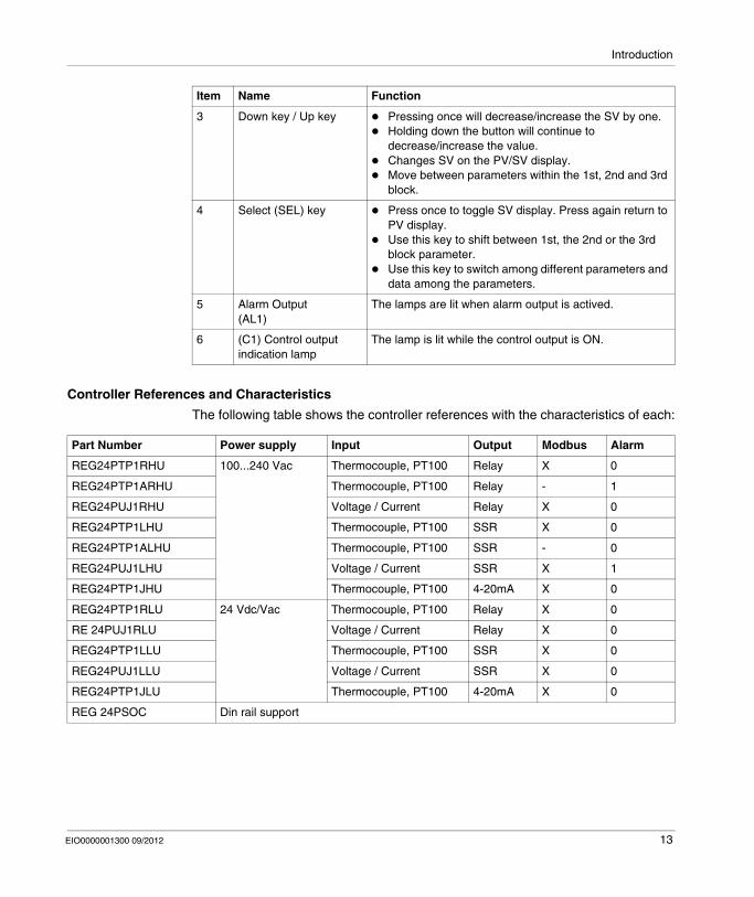
Controller References and Characteristics
The following table shows the controller references with the characteristics of each:
3 Down key / Up key Pressing once will decrease/increase the SV by one.Holding down the button will continue to decrease/increase the value.Changes SV on the PV/SV display. Move between parameters within the 1st, 2nd and 3rd block.
4 Select (SEL) key Press once to toggle SV display. Press again return to PV display.Use this key to shift between 1st, the 2nd or the 3rd block parameter.Use this key to switch among different parameters and data among the parameters.
5 Alarm Output(AL1)
The lamps are lit when alarm output is actived.
6 (C1) Control output indication lamp
The lamp is lit while the control output is ON.
Item Name Function
Part Number Power supply Input Output Modbus Alarm
REG24PTP1RHU 100...240 Vac Thermocouple, PT100 Relay X 0
REG24PTP1ARHU Thermocouple, PT100 Relay - 1
REG24PUJ1RHU Voltage / Current Relay X 0
REG24PTP1LHU Thermocouple, PT100 SSR X 0
REG24PTP1ALHU Thermocouple, PT100 SSR - 0
REG24PUJ1LHU Voltage / Current SSR X 1
REG24PTP1JHU Thermocouple, PT100 4-20mA X 0
REG24PTP1RLU 24 Vdc/Vac Thermocouple, PT100 Relay X 0
RE 24PUJ1RLU Voltage / Current Relay X 0
REG24PTP1LLU Thermocouple, PT100 SSR X 0
REG24PUJ1LLU Voltage / Current SSR X 0
REG24PTP1JLU Thermocouple, PT100 4-20mA X 0
REG 24PSOC Din rail support
EIO0000001300 09/2012 13
Introduction
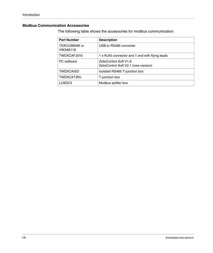
Modbus Communication Accessories
The following table shows the accessories for modbus communication:
Part Number Description
TSXCUSB485 or VW3A8118
USB to RS485 converter
TWDXCAFJ010 1 x RJ45 connector and 1 end with flying leads
PC software ZelioControl Soft V1.6ZelioControl Soft V2.1 (new version)
TWDXCAISO Isolated RS485 T-junction box
TWDXCAT3RJ T-junction box
LU9GC3 Modbus splitter box
14 EIO0000001300 09/2012
Introduction
Main Characteristics
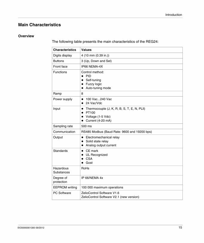
Overview
The following table presents the main characteristics of the REG24:
Characteristics Values
Digits display 4 (10 mm (0.39 in.))
Buttons 3 (Up, Down and Sel)
Front face IP66 NEMA-4X
Functions Control method:PIDSelf-tuningFuzzy logicAuto-tuning mode
Ramp 8
Power supply 100 Vac...240 Vac24 Vac/Vdc
Input Thermocouple (J, K, R, B, S, T, E, N, PLll)PT100Voltage (1-5 Vdc)Current (4-20 mA)
Sampling rate 500 ms
Communication RS485 Modbus (Baud Rate: 9600 and 19200 bps)
Output Electromechanical relaySolid state relayAnalog output current
Standards CE markUL RecognizedCSAGost
Hazardous Substances
RoHs
Degree of protection
IP 66/NEMA 4x
EEPROM writing 100 000 maximum operations
PC Software ZelioControl Software V1.6ZelioControl Software V2.1 (new version)
EIO0000001300 09/2012 15

Introduction
16 EIO0000001300 09/2012
EIO0000001300 09/2012
2
Zelio Control
Hardware of REG24
EIO0000001300 09/2012
Hardware of REG24
What Is in This Chapter?
This chapter contains the following topics:
Topic Page
Electrical and Environmental Characteristics 18
Dimensions and Installation of REG24 20
Wiring of REG24 27
17
Hardware of REG24
Electrical and Environmental Characteristics
Electrical Characteristics of REG24
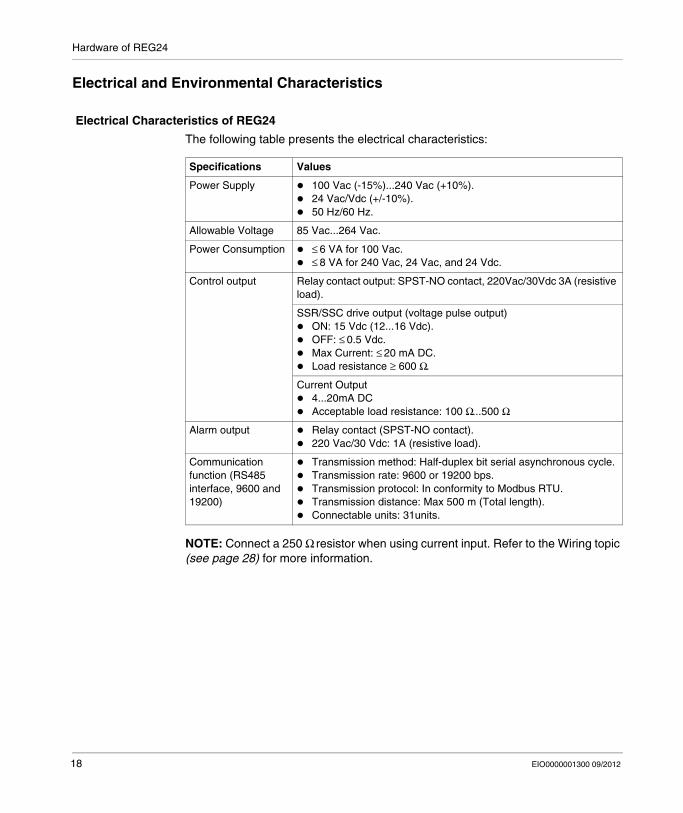
The following table presents the electrical characteristics:
NOTE: Connect a 250 Ω resistor when using current input. Refer to the Wiring topic (see page 28) for more information.
Specifications Values
Power Supply 100 Vac (-15%)...240 Vac (+10%).24 Vac/Vdc (+/-10%).50 Hz/60 Hz.
Allowable Voltage 85 Vac...264 Vac.
Power Consumption ≤ 6 VA for 100 Vac.≤ 8 VA for 240 Vac, 24 Vac, and 24 Vdc.
Control output Relay contact output: SPST-NO contact, 220Vac/30Vdc 3A (resistive load).
SSR/SSC drive output (voltage pulse output)ON: 15 Vdc (12...16 Vdc).OFF: ≤ 0.5 Vdc.Max Current: ≤ 20 mA DC. Load resistance ≥ 600 Ω.
Current Output4...20mA DCAcceptable load resistance: 100 Ω...500 Ω
Alarm output Relay contact (SPST-NO contact).220 Vac/30 Vdc: 1A (resistive load).
Communication function (RS485 interface, 9600 and 19200)
Transmission method: Half-duplex bit serial asynchronous cycle.Transmission rate: 9600 or 19200 bps.Transmission protocol: In conformity to Modbus RTU.Transmission distance: Max 500 m (Total length).Connectable units: 31units.
18 EIO0000001300 09/2012
Hardware of REG24
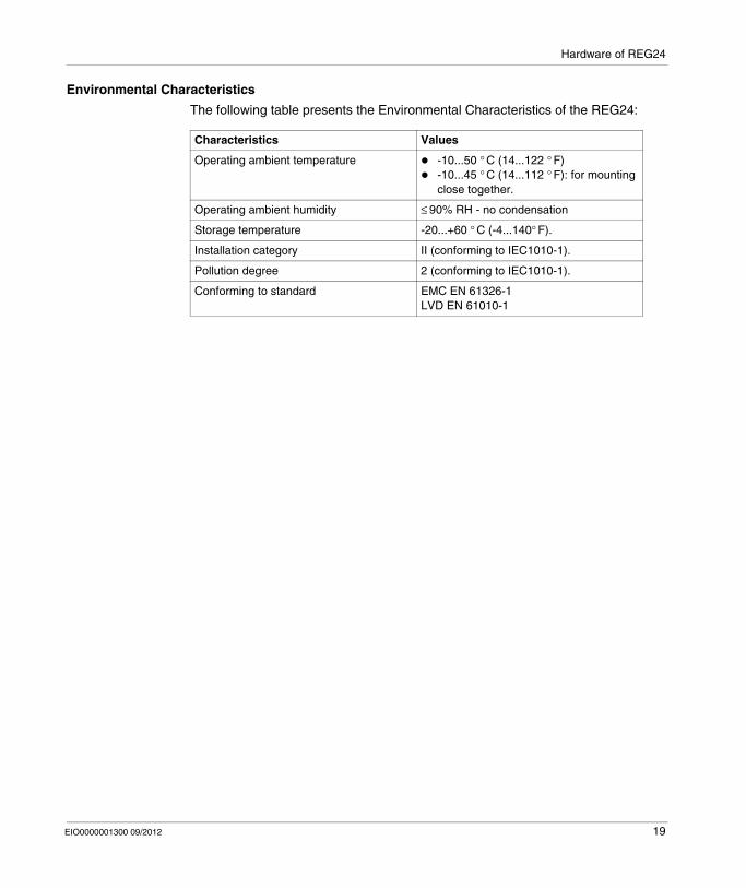
Environmental Characteristics
The following table presents the Environmental Characteristics of the REG24:
Characteristics Values
Operating ambient temperature -10...50 ° C (14...122 ° F)-10...45 ° C (14...112 ° F): for mounting close together.
Operating ambient humidity ≤ 90% RH - no condensation
Storage temperature -20...+60 ° C (-4...140° F).
Installation category II (conforming to IEC1010-1).
Pollution degree 2 (conforming to IEC1010-1).
Conforming to standard EMC EN 61326-1LVD EN 61010-1
EIO0000001300 09/2012 19
Hardware of REG24
Dimensions and Installation of REG24
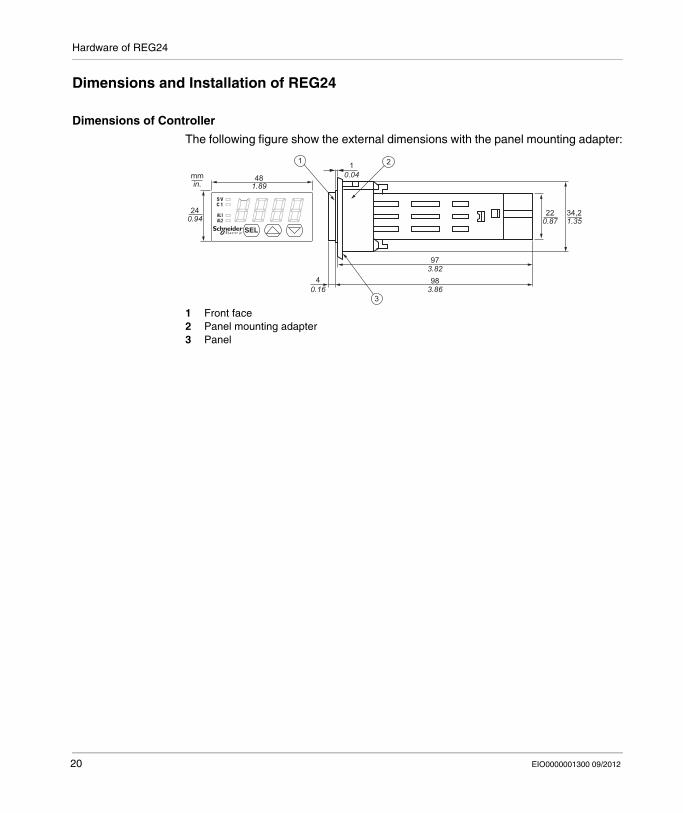
Dimensions of Controller
The following figure show the external dimensions with the panel mounting adapter:
1 Front face2 Panel mounting adapter3 Panel
10.04
40.16
481.89
97
983.82
3.86
mmin.
240.94
34,21.35
220.87
1 2
3
20 EIO0000001300 09/2012
Hardware of REG24
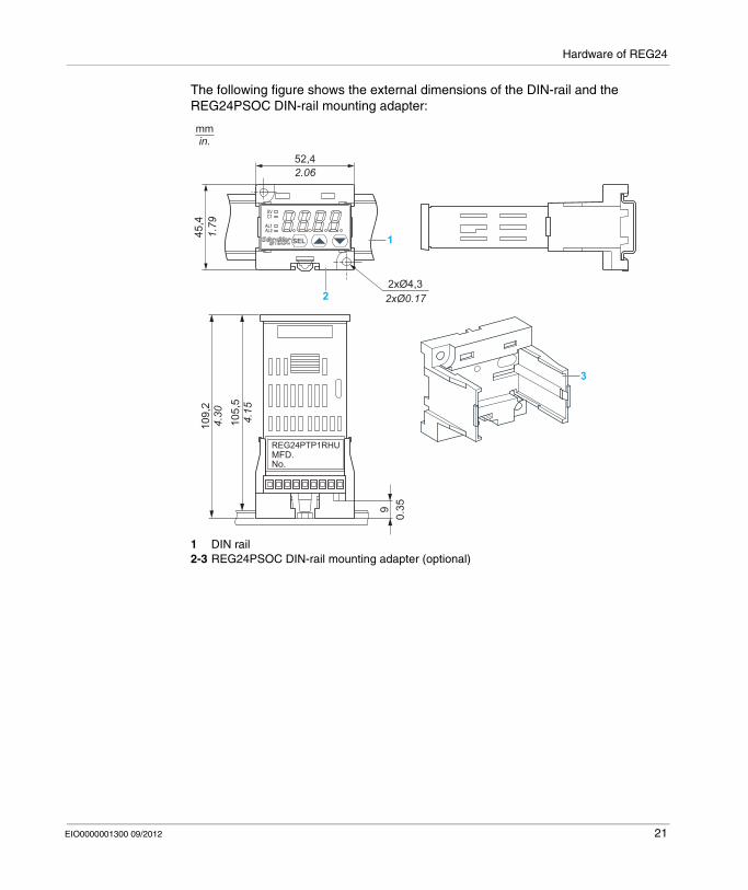
The following figure shows the external dimensions of the DIN-rail and the REG24PSOC DIN-rail mounting adapter:
1 DIN rail2-3 REG24PSOC DIN-rail mounting adapter (optional)
1
22xØ4,32xØ0.17
52,42.06
45,4
1.79
4.30
109,
2
4.15
105,
5
90.
35
REG24PTP1RHUMFD.No.
mmin.
3
EIO0000001300 09/2012 21
Hardware of REG24
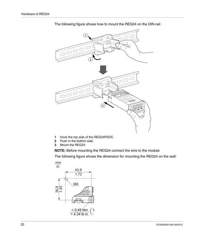
The following figure shows how to mount the REG24 on the DIN-rail:
1 Hook the top side of the REG24PSOC.2 Push in the bottom side.3 Mount the REG24.
NOTE: Before mounting the REG24 connect the wire to the module
The following figure shows the dimension for mounting the REG24 on the wall:
3
2
1
43,81.72
M4
36,8
1.45
< 0,49 Nm< 4.34 lb-in.
mmin.
22 EIO0000001300 09/2012
Hardware of REG24
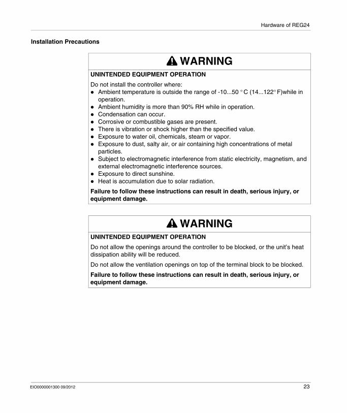
Installation Precautions
WARNINGUNINTENDED EQUIPMENT OPERATION
Do not install the controller where:Ambient temperature is outside the range of -10...50 ° C (14...122° F)while in operation.Ambient humidity is more than 90% RH while in operation.Condensation can occur.Corrosive or combustible gases are present.There is vibration or shock higher than the specified value.Exposure to water oil, chemicals, steam or vapor.Exposure to dust, salty air, or air containing high concentrations of metal particles.Subject to electromagnetic interference from static electricity, magnetism, and external electromagnetic interference sources.Exposure to direct sunshine.Heat is accumulation due to solar radiation.
Failure to follow these instructions can result in death, serious injury, or equipment damage.
WARNINGUNINTENDED EQUIPMENT OPERATION
Do not allow the openings around the controller to be blocked, or the unit’s heat dissipation ability will be reduced.
Do not allow the ventilation openings on top of the terminal block to be blocked.
Failure to follow these instructions can result in death, serious injury, or equipment damage.
EIO0000001300 09/2012 23
Hardware of REG24
NOTE: The front side of this controller conforms to NEMA 4X.
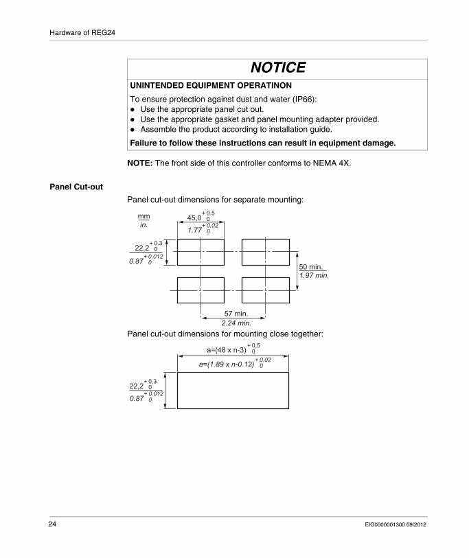
Panel Cut-out
Panel cut-out dimensions for separate mounting:
Panel cut-out dimensions for mounting close together:
NOTICEUNINTENDED EQUIPMENT OPERATINON
To ensure protection against dust and water (IP66):Use the appropriate panel cut out.Use the appropriate gasket and panel mounting adapter provided.Assemble the product according to installation guide.
Failure to follow these instructions can result in equipment damage.
57 min.2.24 min.
22.2
50 min.1.97 min.
+ 0.3 0
mmin.
45,0+ 0.5 0
1.77+ 0.02 0
0.87+ 0.012 0
22,2+ 0,3 0
a=(48 x n-3)+ 0,5 0
a=(1.89 x n-0.12)+ 0.02 0
0.87+ 0.012 0
24 EIO0000001300 09/2012
Hardware of REG24
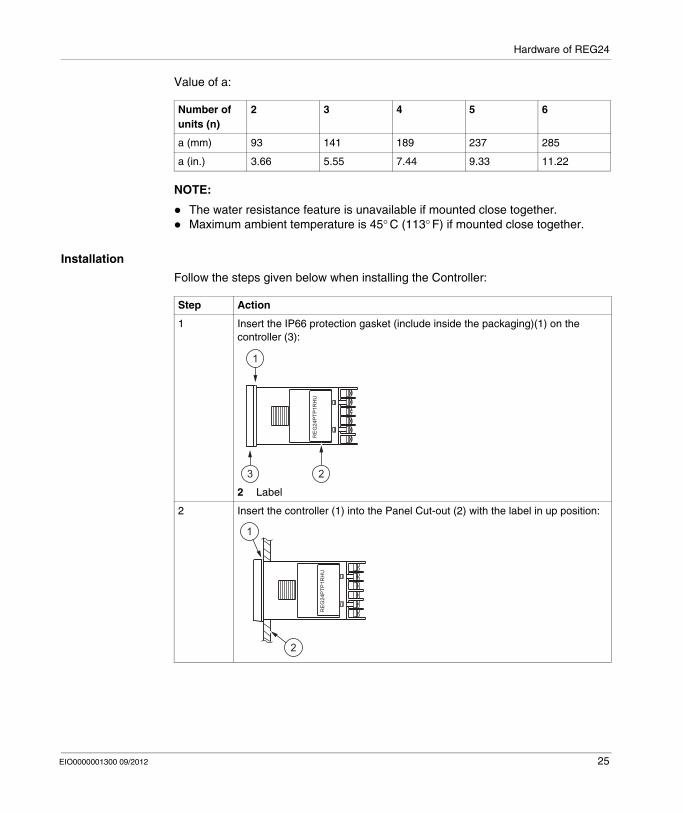
Value of a:
NOTE:
The water resistance feature is unavailable if mounted close together.Maximum ambient temperature is 45° C (113° F) if mounted close together.
Installation
Follow the steps given below when installing the Controller:
Number of units (n)
2 3 4 5 6
a (mm) 93 141 189 237 285
a (in.) 3.66 5.55 7.44 9.33 11.22
Step Action
1 Insert the IP66 protection gasket (include inside the packaging)(1) on the controller (3):
2 Label
2 Insert the controller (1) into the Panel Cut-out (2) with the label in up position:
RE
G24
PTP
1RH
U
1
23
RE
G24
PTP
1RH
U
1
2
EIO0000001300 09/2012 25
Hardware of REG24
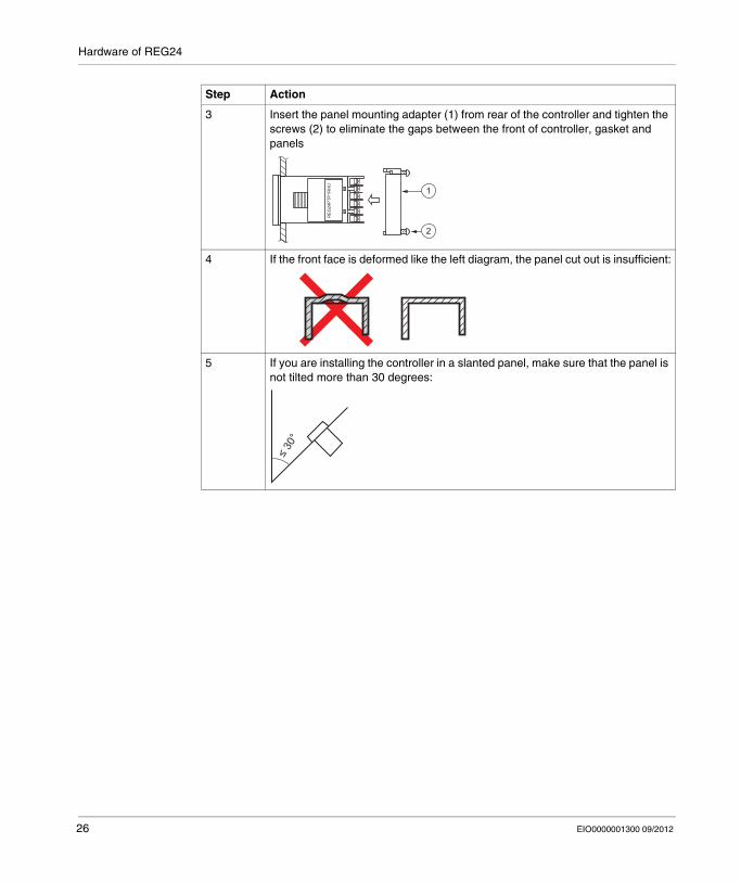
3 Insert the panel mounting adapter (1) from rear of the controller and tighten the screws (2) to eliminate the gaps between the front of controller, gasket and panels
4 If the front face is deformed like the left diagram, the panel cut out is insufficient:
5 If you are installing the controller in a slanted panel, make sure that the panel is not tilted more than 30 degrees:
Step Action
RE
G24
PTP
1RH
U
1
2
26 EIO0000001300 09/2012
Hardware of REG24
Wiring of REG24
Overview
Wiring Installation Instructions
For the thermocouple sensor type, use thermocouple compensation wires for wiring.For the RTD type, use a wiring material with a small lead wire resistance and no resistance differentials among three wires.Keep input lines away from power line and load line to avoid the influence from electromagnetic interference induced.For the input and output signal lines, be sure to use shielded wires and keep them properly segregated from each other.If an electromagnetic interference level is excessive in the power supply, the additional installation of an insulating transformer and the use of an electromagnetic interference filter are recommended.Use stranded power supply cable for the instrument.For the unit with an alarm against a burn-out in the heater, use the same power line for connection of the power supplies for the heater and the controller.A setup time is required for the contact output when the power is turned on. If the contact output is used as a signal for an external interlock circuit, use a delay relay at the same time.Use the auxiliary relay since the unit’s operational life is shortened if full capacity load is connected to the output relay. Use the SSR/SSC drive output type if the output operations occur frequently.
DANGERHAZARD OF ELECTRIC SHOCK, EXPLOSION OR ARC FLASH
Remove all power from the controller.Always use a properly rated voltage sensing device to confirm power is off.Use only the specified voltage when operating the controller.
Failure to follow these instructions will result in death or serious injury.
EIO0000001300 09/2012 27
Hardware of REG24
If an inductive load such as magnetic switches connected as a relay output load, use a protection module (Free wheel Diode or RC circuit or Varistor).Use a non-grounded sensor for resistance bulb or thermocouple of the SSR/SSC-driven output, output of 4...20 mA dc.
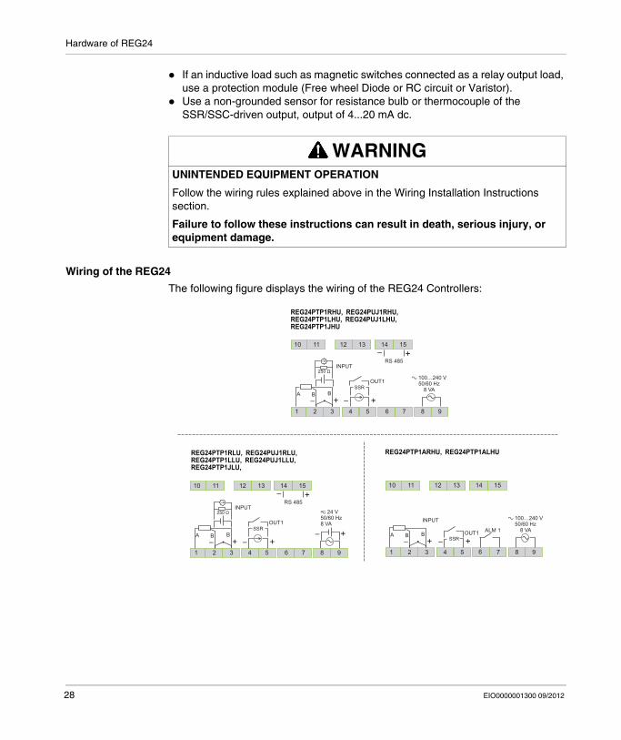
Wiring of the REG24
The following figure displays the wiring of the REG24 Controllers:
WARNINGUNINTENDED EQUIPMENT OPERATION
Follow the wiring rules explained above in the Wiring Installation Instructions section.
Failure to follow these instructions can result in death, serious injury, or equipment damage.
z 24 V50/60 Hz8 VA
REG24PTP1RHU, REG24PUJ1RHU,REG24PTP1LHU, REG24PUJ1LHU,REG24PTP1JHU
REG24PTP1RLU, REG24PUJ1RLU,REG24PTP1LLU, REG24PUJ1LLU,REG24PTP1JLU,
REG24PTP1ARHU, REG24PTP1ALHU
10 11 12 13 14 15
1 2 3 4 5+
+
– +–
–
6 7 8 9
RS 485
OUT1
INPUT
B BA
a 100…240 V50/60 Hz
8 VA
+–
10 11 12 13 14 15
1 2 3 4 5
+–
6 7 8 9
RS 485
a 100…240 V50/60 Hz
8 VA
7 8 9
ALM 1
6
10 11 12 13 14 15
1 2 3 4 5+–OUT1
+– +–
OUT1
INPUT
B BASSR
p
– – +–B BA
p
– –
INPUT
SSR
SSR
p
– –
28 EIO0000001300 09/2012
Hardware of REG24
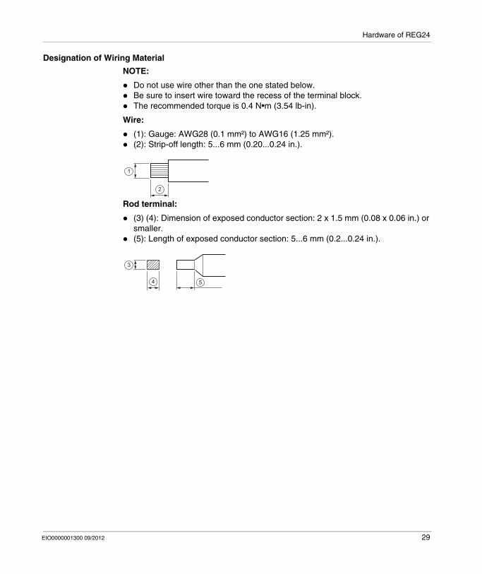
Designation of Wiring Material
NOTE:
Do not use wire other than the one stated below.Be sure to insert wire toward the recess of the terminal block.The recommended torque is 0.4 N•m (3.54 lb-in).
Wire:
(1): Gauge: AWG28 (0.1 mm²) to AWG16 (1.25 mm²).(2): Strip-off length: 5...6 mm (0.20...0.24 in.).
Rod terminal:
(3) (4): Dimension of exposed conductor section: 2 x 1.5 mm (0.08 x 0.06 in.) or smaller.(5): Length of exposed conductor section: 5...6 mm (0.2...0.24 in.).
1
2
3
4 5
EIO0000001300 09/2012 29

Hardware of REG24
30 EIO0000001300 09/2012
EIO0000001300 09/2012
3
Zelio Control
Configuration of REG24
EIO0000001300 09/2012
Configuration of REG24
What Is in This Chapter?
This chapter contains the following topics:
Topic Page
How to Configure Using Front panel 32
Basic Operations 33
Key Lock 35
Setting the Temperature Controller 37
Parameters List 41
31
Configuration of REG24
How to Configure Using Front panel
Overview
To configure the module you can use the Keys on the Panel or for more information refer to the Zelio Control, REG Communication and ZelioControl Soft Installation (see page 8).
NOTE: Some parameters are not displayed on the panel depending on different models or masking the parameters in purpose or depending on the selection of KeyLoc for modifiable parameters.
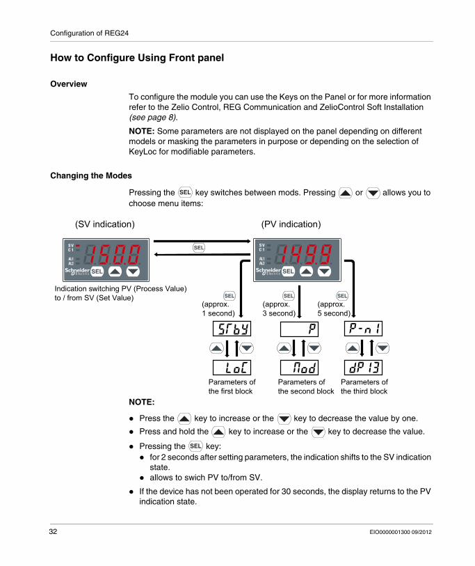
Changing the Modes
Pressing the key switches between mods. Pressing or allows you to choose menu items:
NOTE:
Press the key to increase or the key to decrease the value by one.
Press and hold the key to increase or the key to decrease the value.
Pressing the key:for 2 seconds after setting parameters, the indication shifts to the SV indication state.allows to swich PV to/from SV.
If the device has not been operated for 30 seconds, the display returns to the PV indication state.
(PV indication)(SV indication)
(approx.1 second)
Parameters ofthe first block
Parameters ofthe second block
Parameters ofthe third block
(approx.3 second)
(approx.5 second)
Indication switching PV (Process Value)to / from SV (Set Value)
32 EIO0000001300 09/2012
Configuration of REG24
Basic Operations
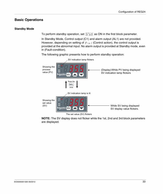
Standby Mode
To perform standby operation, set as ON in the first block parameter.
In Standby Mode, Control output (C1) and alarm output (AL1) are not provided. However, depending on setting of (Control action), the control output is provided at the abnormal input. No alarm output is provided at Standby mode, even in (Fault-condition).
The following graphic presents how to perform standby operation:
NOTE: The SV display does not flicker while the 1st, 2nd and 3rd block parameters are displayed.
(Display) While PV being displayedSV indication lamp flickers
While SV being displayedSV display value flickers.
Press the
SV indication lamp is lit
SV indication lamp flickers
The set value (SV) flickers
Showing the processvalue (PV)
Showing the set value(SV)
once
EIO0000001300 09/2012 33
Configuration of REG24
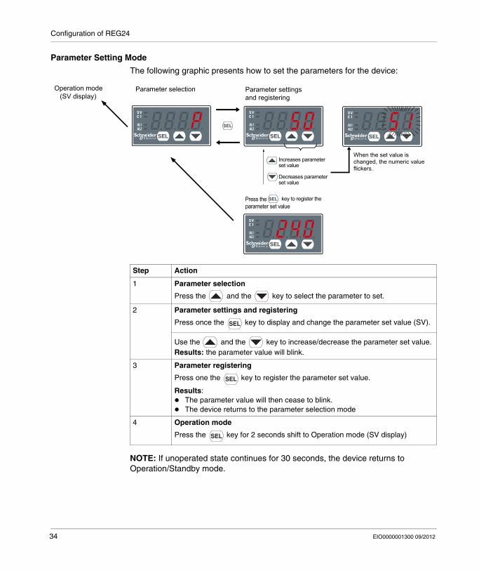
Parameter Setting Mode
The following graphic presents how to set the parameters for the device:
NOTE: If unoperated state continues for 30 seconds, the device returns to Operation/Standby mode.
Operation mode (SV display)
Parameter settingsand registering
Increases parameterset value
Decreases parameter
key to register the
set value
Parameter selection
Press theparameter set value
When the set value is changed, the numeric value flickers.
Step Action
1 Parameter selection
Press the and the key to select the parameter to set.
2 Parameter settings and registering
Press once the key to display and change the parameter set value (SV).
Use the and the key to increase/decrease the parameter set value.Results: the parameter value will blink.
3 Parameter registering
Press one the key to register the parameter set value.
Results:The parameter value will then cease to blink.The device returns to the parameter selection mode
4 Operation mode
Press the key for 2 seconds shift to Operation mode (SV display)
34 EIO0000001300 09/2012
Configuration of REG24
Key Lock
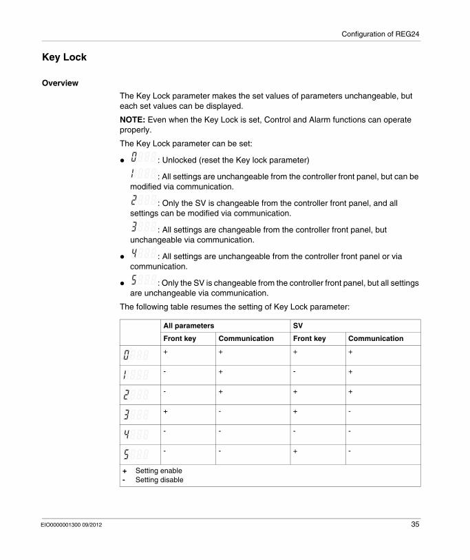
Overview
The Key Lock parameter makes the set values of parameters unchangeable, but each set values can be displayed.
NOTE: Even when the Key Lock is set, Control and Alarm functions can operate properly.
The Key Lock parameter can be set:
: Unlocked (reset the Key lock parameter)
: All settings are unchangeable from the controller front panel, but can be modified via communication.
: Only the SV is changeable from the controller front panel, and all settings can be modified via communication.
: All settings are changeable from the controller front panel, but unchangeable via communication.
: All settings are unchangeable from the controller front panel or via communication.
: Only the SV is changeable from the controller front panel, but all settings are unchangeable via communication.
The following table resumes the setting of Key Lock parameter:
All parameters SV
Front key Communication Front key Communication
+ + + +
- + - +
- + + +
+ - + -
- - - -
- - + -
+ Setting enable- Setting disable
EIO0000001300 09/2012 35
Configuration of REG24
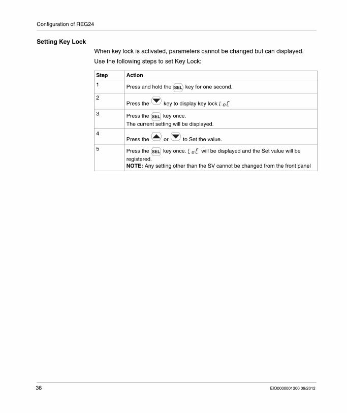
Setting Key Lock
When key lock is activated, parameters cannot be changed but can displayed.
Use the following steps to set Key Lock:
Step Action
1 Press and hold the key for one second.
2Press the key to display key lock
3 Press the key once.
The current setting will be displayed.
4Press the or to Set the value.
5 Press the key once. will be displayed and the Set value will be
registered.NOTE: Any setting other than the SV cannot be changed from the front panel
36 EIO0000001300 09/2012
Configuration of REG24
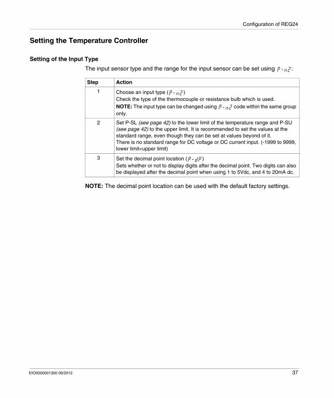
Setting the Temperature Controller
Setting of the Input Type
The input sensor type and the range for the input sensor can be set using :
NOTE: The decimal point location can be used with the default factory settings.
Step Action
1 Choose an input type ( )Check the type of the thermocouple or resistance bulb which is used.NOTE: The input type can be changed using code within the same group only.
2 Set P-SL (see page 42) to the lower limit of the temperature range and P-SU (see page 42) to the upper limit. It is recommended to set the values at the standard range, even though they can be set at values beyond of it.There is no standard range for DC voltage or DC current input. (-1999 to 9999, lower limit<upper limit)
3 Set the decimal point location ( )Sets whether or not to display digits after the decimal point. Two digits can also be displayed after the decimal point when using 1 to 5Vdc, and 4 to 20mA dc.
EIO0000001300 09/2012 37
Configuration of REG24
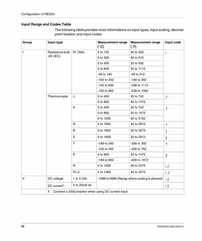
Input Range and Codes Table
The following table provides more informations on input types, input scaling, decimal point location and input codes:
Group Input type Measurement range [° C]
Measurement range [° F]
Input code
I Resistance bulb JIS (IEC)
Pt 100Ω 0 to 150 32 to 302
0 to 300 32 to 572
0 to 500 32 to 932
0 to 600 32 to 1112
-50 to 100 -58 to 212
-100 to 200 -148 to 392
-150 to 600 -238 to 1112
-150 to 850 -228 to 1562
Thermocouple J 0 to 400 32 to 752
0 to 800 32 to 1472
K 0 to 400 32 to 752
0 to 800 32 to 1472
0 to 1200 32 to 2192
R 0 to 1600 32 to 2912
B 0 to 1800 32 to 3272
S 0 to 1600 32 to 2912
T -199 to 200 -328 to 392
-150 to 400 -238 to 752
E 0 to 800 32 to 1472
-199 to 800 -328 to 1472
N 0 to 1300 32 to 2372
PL-2 0 to 1300 32 to 2372
II DC voltage 1 to 5 Vdc -1999 to 9999 (Range where scaling is allowed)
DC current1 4 to 20mA dc
1 Connect a 250Ω resistor when using DC current input.
38 EIO0000001300 09/2012
Configuration of REG24
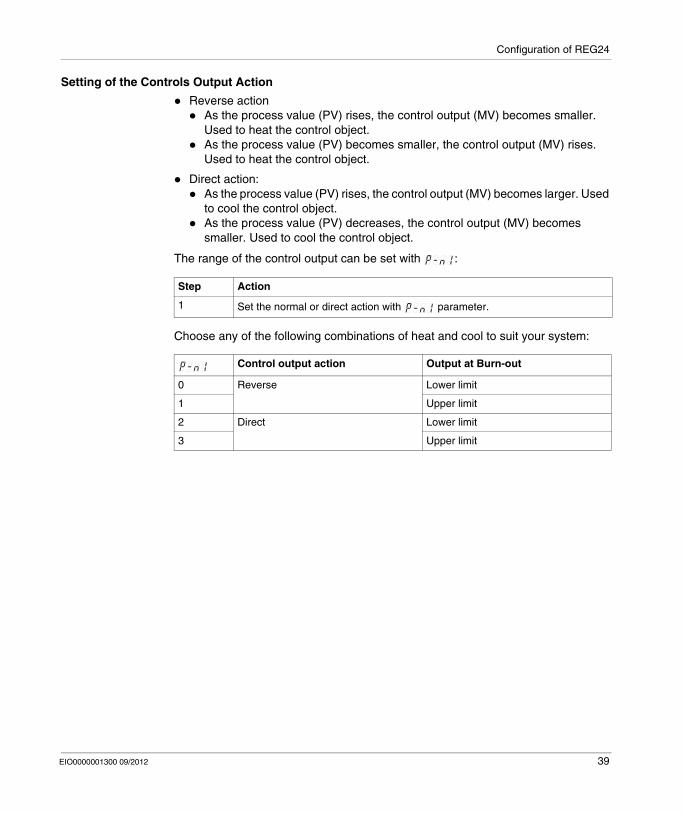
Setting of the Controls Output Action
Reverse actionAs the process value (PV) rises, the control output (MV) becomes smaller. Used to heat the control object.As the process value (PV) becomes smaller, the control output (MV) rises. Used to heat the control object.
Direct action:As the process value (PV) rises, the control output (MV) becomes larger. Used to cool the control object.As the process value (PV) decreases, the control output (MV) becomes smaller. Used to cool the control object.
The range of the control output can be set with :
Choose any of the following combinations of heat and cool to suit your system:
Step Action
1 Set the normal or direct action with parameter.
Control output action Output at Burn-out
0 Reverse Lower limit
1 Upper limit
2 Direct Lower limit
3 Upper limit
EIO0000001300 09/2012 39
Configuration of REG24
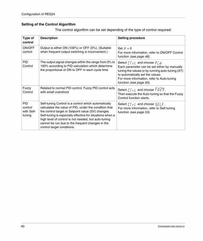
Setting of the Control Algorithm
The control algorithm can be set depending of the type of control required:
Type of control
Description Setting procedure
ON/OFF control
Output is either ON (100%) or OFF (0%). (Suitable when frequent output switching is inconvenient.)
Set = 0For more information, refer to ON/OFF Control function (see page 48).
PID Control
The output signal changes within the range from 0% to 100% according to PID calculation which determine the proportional of ON to OFF in each cycle time
Select and choose .Each parameter can be set either by manually tuning the values or by running auto-tuning (AT) to automatically set the values.For more information, refer to Auto-tuning function (see page 50).
Fuzzy Control
Related to normal PID control, Fuzzy PID control acts with small overshoot
Select and choose .Then execute the Auto-tuning so that the Fuzzy Control function starts.
PID control with Self-tuning
Self-tuning Control is a control which automatically calculates the value of PID, under the condition that the control target or Setpoint value (SV) changes.Self-tuning is especially effective for situations when a high level of control is not needed, but auto-tuning cannot be run due to the frequent changes in the control target conditions.
Select and choose .For more information, refer to Self-tuning function (see page 53).
40 EIO0000001300 09/2012
Configuration of REG24
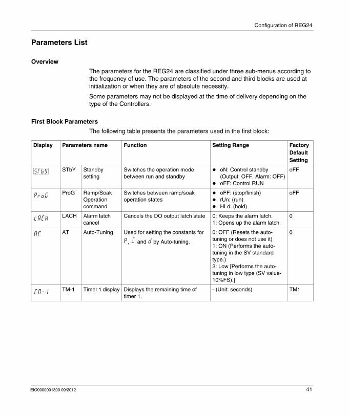
Parameters List
Overview
The parameters for the REG24 are classified under three sub-menus according to the frequency of use. The parameters of the second and third blocks are used at initialization or when they are of absolute necessity.
Some parameters may not be displayed at the time of delivery depending on the type of the Controllers.
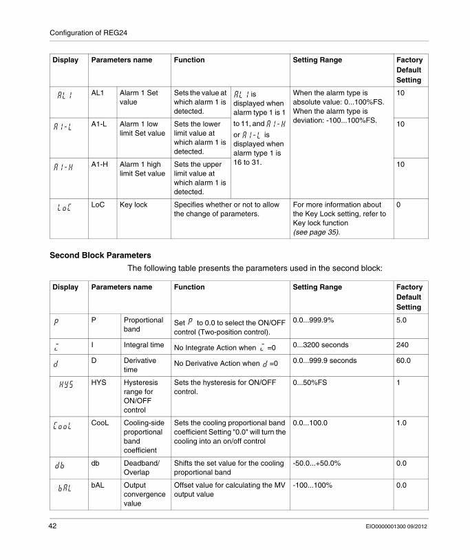
First Block Parameters
The following table presents the parameters used in the first block:
Display Parameters name Function Setting Range Factory Default Setting
STbY Standby setting
Switches the operation mode between run and standby
oN: Control standby (Output: OFF, Alarm: OFF)oFF: Control RUN
oFF
ProG Ramp/Soak Operation command
Switches between ramp/soak operation states
oFF: (stop/finish)rUn: (run)HLd: (hold)
oFF
LACH Alarm latch cancel
Cancels the DO output latch state 0: Keeps the alarm latch.1: Opens up the alarm latch.
0
AT Auto-Tuning Used for setting the constants for
, and by Auto-tuning.
0: OFF (Resets the auto-tuning or does not use it)1: ON (Performs the auto-tuning in the SV standard type.)2: Low [Performs the auto-tuning in low type (SV value-10%FS).]
0
TM-1 Timer 1 display Displays the remaining time of timer 1.
- (Unit: seconds) TM1
EIO0000001300 09/2012 41
Configuration of REG24
Second Block Parameters
The following table presents the parameters used in the second block:
AL1 Alarm 1 Set value
Sets the value at which alarm 1 is detected.
is displayed when alarm type 1 is 1
to 11, and
or is displayed when alarm type 1 is 16 to 31.
When the alarm type is absolute value: 0...100%FS.When the alarm type is deviation: -100...100%FS.
10
A1-L Alarm 1 low limit Set value
Sets the lower limit value at which alarm 1 is detected.
10
A1-H Alarm 1 high limit Set value
Sets the upper limit value at which alarm 1 is detected.
10
LoC Key lock Specifies whether or not to allow the change of parameters.
For more information about the Key Lock setting, refer to Key lock function (see page 35).
0
Display Parameters name Function Setting Range Factory Default Setting
Display Parameters name Function Setting Range Factory Default Setting
P Proportional band
Set to 0.0 to select the ON/OFF control (Two-position control).
0.0...999.9% 5.0
I Integral time No Integrate Action when =0 0...3200 seconds 240
D Derivative time
No Derivative Action when =0 0.0...999.9 seconds 60.0
HYS Hysteresis range for ON/OFF control
Sets the hysteresis for ON/OFF control.
0...50%FS 1
CooL Cooling-side proportional band coefficient
Sets the cooling proportional band coefficient Setting "0.0" will turn the cooling into an on/off control
0.0...100.0 1.0
db Deadband/ Overlap
Shifts the set value for the cooling proportional band
-50.0...+50.0% 0.0
bAL Output convergence value
Offset value for calculating the MV output value
-100...100% 0.0
42 EIO0000001300 09/2012
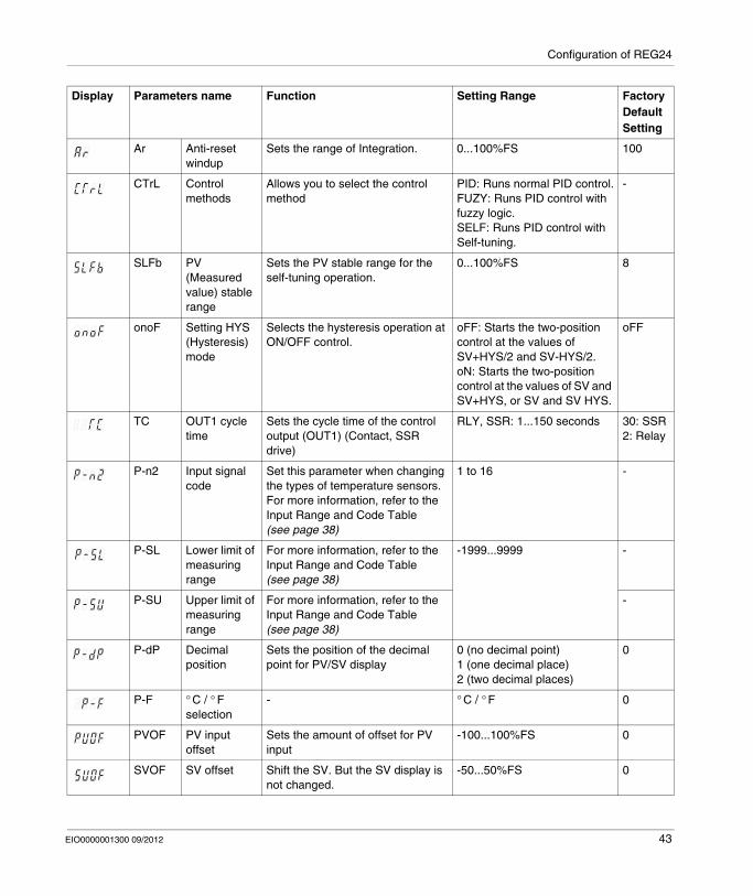
Configuration of REG24
Ar Anti-reset windup
Sets the range of Integration. 0...100%FS 100
CTrL Control methods
Allows you to select the control method
PID: Runs normal PID control.FUZY: Runs PID control with fuzzy logic.SELF: Runs PID control with Self-tuning.
-
SLFb PV (Measured value) stable range
Sets the PV stable range for the self-tuning operation.
0...100%FS 8
onoF Setting HYS (Hysteresis) mode
Selects the hysteresis operation at ON/OFF control.
oFF: Starts the two-position control at the values of SV+HYS/2 and SV-HYS/2.oN: Starts the two-position control at the values of SV and SV+HYS, or SV and SV HYS.
oFF
TC OUT1 cycle time
Sets the cycle time of the control output (OUT1) (Contact, SSR drive)
RLY, SSR: 1...150 seconds 30: SSR2: Relay
P-n2 Input signal code
Set this parameter when changing the types of temperature sensors.For more information, refer to the Input Range and Code Table (see page 38)
1 to 16 -
P-SL Lower limit of measuring range
For more information, refer to the Input Range and Code Table (see page 38)
-1999...9999 -
P-SU Upper limit of measuring range
For more information, refer to the Input Range and Code Table (see page 38)
-
P-dP Decimal position
Sets the position of the decimal point for PV/SV display
0 (no decimal point)1 (one decimal place)2 (two decimal places)
0
P-F ° C / ° F selection
- ° C / ° F 0
PVOF PV input offset
Sets the amount of offset for PV input
-100...100%FS 0
SVOF SV offset Shift the SV. But the SV display is not changed.
-50...50%FS 0
Display Parameters name Function Setting Range Factory Default Setting
EIO0000001300 09/2012 43
Configuration of REG24
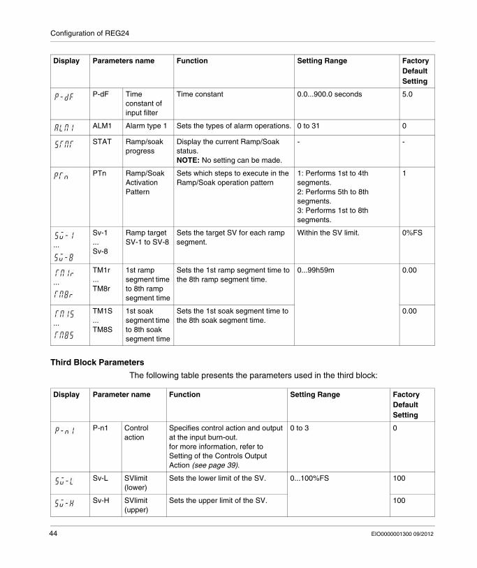
Third Block Parameters
The following table presents the parameters used in the third block:
P-dF Time constant of input filter
Time constant 0.0...900.0 seconds 5.0
ALM1 Alarm type 1 Sets the types of alarm operations. 0 to 31 0
STAT Ramp/soak progress
Display the current Ramp/Soak status. NOTE: No setting can be made.
- -
PTn Ramp/Soak Activation Pattern
Sets which steps to execute in the Ramp/Soak operation pattern
1: Performs 1st to 4th segments.2: Performs 5th to 8th segments.3: Performs 1st to 8th segments.
1
...
Sv-1...Sv-8
Ramp target SV-1 to SV-8
Sets the target SV for each ramp segment.
Within the SV limit. 0%FS
...
TM1r ...TM8r
1st ramp segment time to 8th ramp segment time
Sets the 1st ramp segment time to the 8th ramp segment time.
0...99h59m 0.00
...
TM1S...TM8S
1st soak segment time to 8th soak segment time
Sets the 1st soak segment time to the 8th soak segment time.
0.00
Display Parameters name Function Setting Range Factory Default Setting
Display Parameter name Function Setting Range Factory Default Setting
P-n1 Control action
Specifies control action and output at the input burn-out.for more information, refer to Setting of the Controls Output Action (see page 39).
0 to 3 0
Sv-L SVlimit (lower)
Sets the lower limit of the SV. 0...100%FS 100
Sv-H SVlimit (upper)
Sets the upper limit of the SV. 100
44 EIO0000001300 09/2012
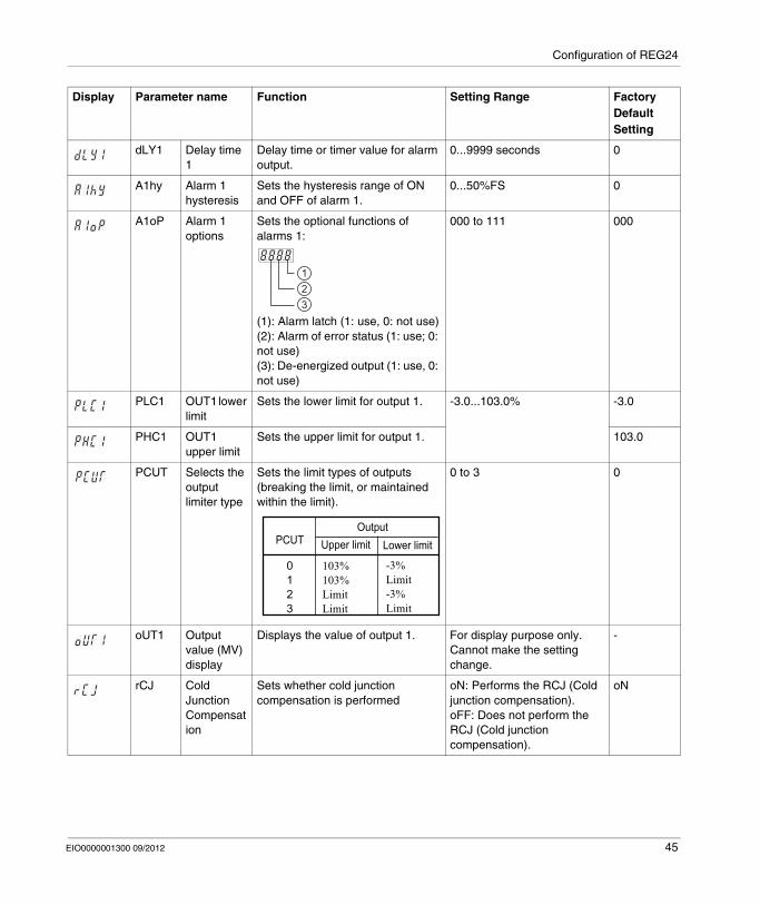
Configuration of REG24
dLY1 Delay time 1
Delay time or timer value for alarm output.
0...9999 seconds 0
A1hy Alarm 1 hysteresis
Sets the hysteresis range of ON and OFF of alarm 1.
0...50%FS 0
A1oP Alarm 1 options
Sets the optional functions of alarms 1:
(1): Alarm latch (1: use, 0: not use)(2): Alarm of error status (1: use; 0: not use)(3): De-energized output (1: use, 0: not use)
000 to 111 000
PLC1 OUT1 lower limit
Sets the lower limit for output 1. -3.0...103.0% -3.0
PHC1 OUT1 upper limit
Sets the upper limit for output 1. 103.0
PCUT Selects the output limiter type
Sets the limit types of outputs (breaking the limit, or maintained within the limit).
0 to 3 0
oUT1 Output value (MV) display
Displays the value of output 1. For display purpose only. Cannot make the setting change.
-
rCJ Cold Junction Compensation
Sets whether cold junction compensation is performed
oN: Performs the RCJ (Cold junction compensation).oFF: Does not perform the RCJ (Cold junction compensation).
oN
Display Parameter name Function Setting Range Factory Default Setting
123
PCUT
0123
103%103%LimitLimit
-3%Limit-3%Limit
OutputUpper limit Lower limit
EIO0000001300 09/2012 45
Configuration of REG24
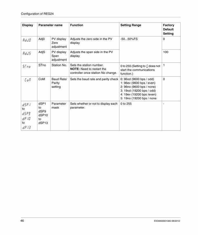
Adj0 PV display Zero adjustment
Adjusts the zero side in the PV display
-50...50%FS 0
AdjS PV display Span adjustment
Adjusts the span side in the PV display
100
STno Station No. Sets the station number.NOTE: Need to restart the controller once station No change.
0 to 255 (Setting to does not start the communications function.)
1
CoM Baud Rate/ Parity setting
Sets the baud rate and parity check 0: 96od (9600 bps / odd)1: 96ev (9600 bps / even)2: 96no (9600 bps / none)3: 19od (19200 bps / odd)4: 19ev (19200 bps /even)5: 19no (19200 bps / none
0
to
to
dSP1todSP9dSP10todSP13
Parameter mask
Sets whether or not to display each parameter.
0 to 255 -
Display Parameter name Function Setting Range Factory Default Setting
46 EIO0000001300 09/2012
EIO0000001300 09/2012
4
Zelio Control
Main Functions of REG24
EIO0000001300 09/2012
Main Functions of REG24
What Is in This Chapter?
This chapter contains the following topics:
Topic Page
ON/OFF Control 48
Auto-tuning 50
Self-Tuning 53
Alarm Function 55
Ramp/Soak 63
Other Function: Anti-reset windup (Ar) and Output Convergence Value (bAL) 67
47
Main Functions of REG24
ON/OFF Control
Overview
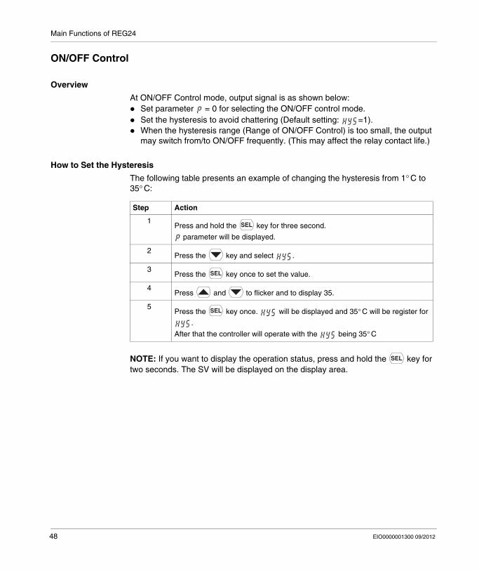
At ON/OFF Control mode, output signal is as shown below:Set parameter = 0 for selecting the ON/OFF control mode.Set the hysteresis to avoid chattering (Default setting: =1).When the hysteresis range (Range of ON/OFF Control) is too small, the output may switch from/to ON/OFF frequently. (This may affect the relay contact life.)
How to Set the Hysteresis
The following table presents an example of changing the hysteresis from 1° C to 35° C:
NOTE: If you want to display the operation status, press and hold the key for two seconds. The SV will be displayed on the display area.
Step Action
1Press and hold the key for three second.
parameter will be displayed.
2Press the key and select .
3Press the key once to set the value.
4Press and to flicker and to display 35.
5Press the key once. will be displayed and 35° C will be register for
.
After that the controller will operate with the being 35° C
48 EIO0000001300 09/2012
Main Functions of REG24
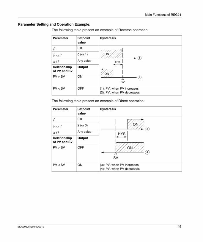
Parameter Setting and Operation Example:
The following table present an example of Reverse operation:
The following table present an example of Direct operation:
Parameter Setpoint value
Hysteresis
0.0
0 (or 1)
Any value
Relationship of PV and SV
Output
PV > SV ON
PV < SV OFF (1): PV, when PV increases(2): PV, when PV decreases
Parameter Setpoint value
Hysteresis
0.0
2 (or 3)
Any value
Relationship of PV and SV
Output
PV > SV OFF
PV < SV ON (3): PV, when PV increases(4): PV, when PV decreases
HYS
SV
1
2
ON
ON
HYS
SV
3
4
ON
ON
EIO0000001300 09/2012 49
Main Functions of REG24
Auto-tuning
Overview
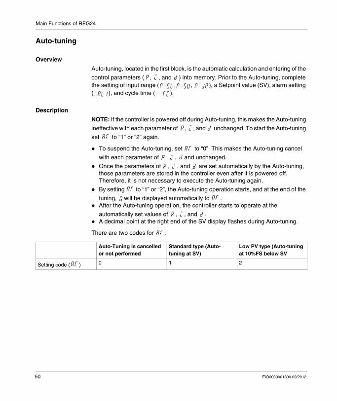
Auto-tuning, located in the first block, is the automatic calculation and entering of the
control parameters ( , , and ) into memory. Prior to the Auto-tuning, complete the setting of input range ( , , ), a Setpoint value (SV), alarm setting ( ), and cycle time ( ).
Description
NOTE: If the controller is powered off during Auto-tuning, this makes the Auto-tuning
ineffective with each parameter of , , and unchanged. To start the Auto-tuning
set to “1” or “2” again.
To suspend the Auto-tuning, set to “0”. This makes the Auto-tuning cancel
with each parameter of , , and unchanged.
Once the parameters of , , and are set automatically by the Auto-tuning, those parameters are stored in the controller even after it is powered off. Therefore, it is not necessary to execute the Auto-tuning again.
By setting to “1” or “2”, the Auto-tuning operation starts, and at the end of the
tuning, will be displayed automatically to .After the Auto-tuning operation, the controller starts to operate at the
automatically set values of , , and .A decimal point at the right end of the SV display flashes during Auto-tuning.
There are two codes for :
Auto-Tuning is cancelled or not performed
Standard type (Auto-tuning at SV)
Low PV type (Auto-tuning at 10%FS below SV
Setting code ( ) 0 1 2
50 EIO0000001300 09/2012
Main Functions of REG24
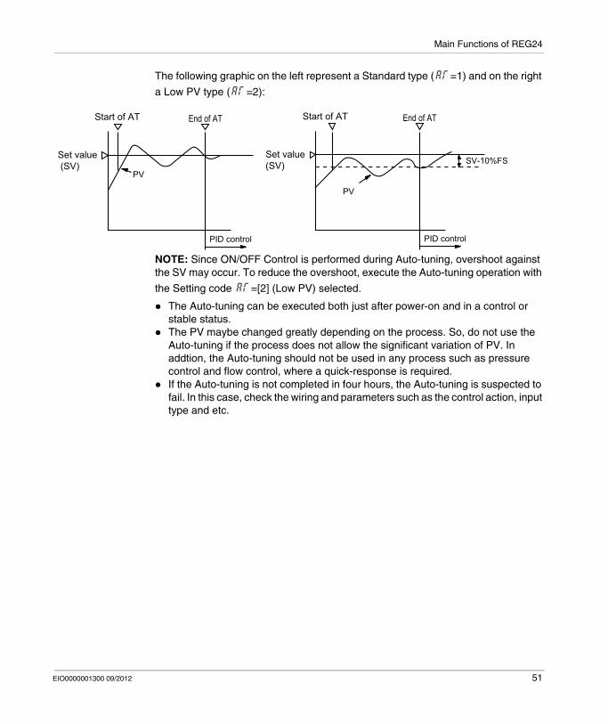
The following graphic on the left represent a Standard type ( =1) and on the right
a Low PV type ( =2):
NOTE: Since ON/OFF Control is performed during Auto-tuning, overshoot against the SV may occur. To reduce the overshoot, execute the Auto-tuning operation with
the Setting code =[2] (Low PV) selected.
The Auto-tuning can be executed both just after power-on and in a control or stable status.The PV maybe changed greatly depending on the process. So, do not use the Auto-tuning if the process does not allow the significant variation of PV. In addtion, the Auto-tuning should not be used in any process such as pressure control and flow control, where a quick-response is required.If the Auto-tuning is not completed in four hours, the Auto-tuning is suspected to fail. In this case, check the wiring and parameters such as the control action, input type and etc.
Start of AT End of AT
PV
PID control
Start of AT End of AT
PV
PID control
SV-10%FSSet value (SV)
Set value (SV)
EIO0000001300 09/2012 51
Main Functions of REG24
How to Set the Auto-tuning
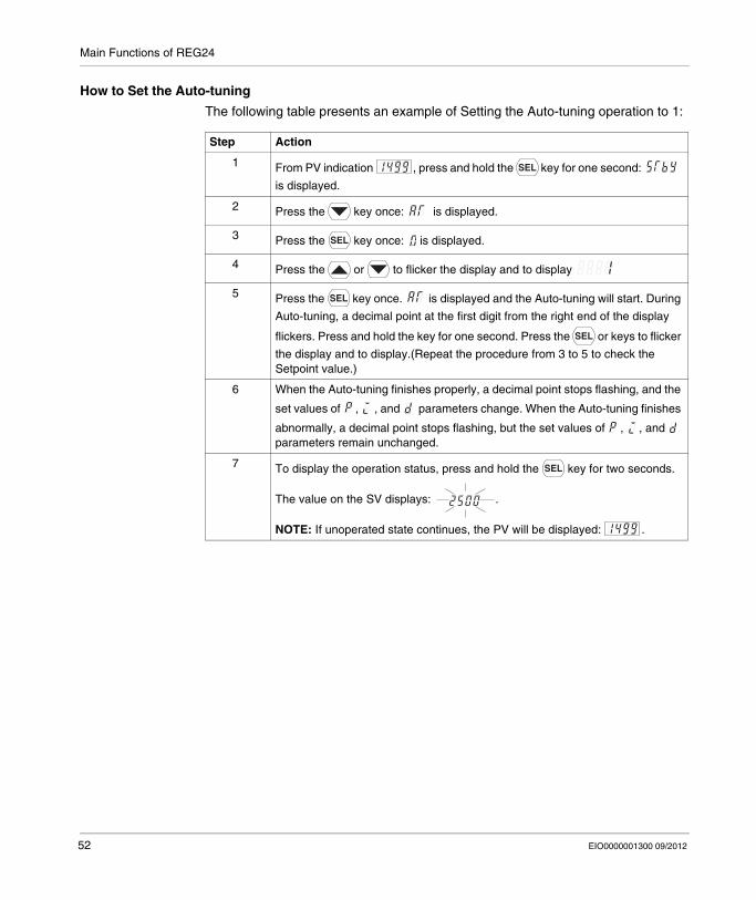
The following table presents an example of Setting the Auto-tuning operation to 1:
Step Action
1 From PV indication , press and hold the key for one second:
is displayed.
2 Press the key once: is displayed.
3 Press the key once: is displayed.
4 Press the or to flicker the display and to display
5 Press the key once. is displayed and the Auto-tuning will start. During
Auto-tuning, a decimal point at the first digit from the right end of the display
flickers. Press and hold the key for one second. Press the or keys to flicker
the display and to display.(Repeat the procedure from 3 to 5 to check the Setpoint value.)
6 When the Auto-tuning finishes properly, a decimal point stops flashing, and the
set values of , , and parameters change. When the Auto-tuning finishes
abnormally, a decimal point stops flashing, but the set values of , , and parameters remain unchanged.
7 To display the operation status, press and hold the key for two seconds.
The value on the SV displays: .
NOTE: If unoperated state continues, the PV will be displayed: .
52 EIO0000001300 09/2012
Main Functions of REG24
Self-Tuning
Overview
Self-tuning Control is a control which automatically calculates the value of PID, under the condition that the control target or Setpoint value (SV) changes. Self-tuning is especially effective for situations when a high level of control is not needed, but auto-tuning cannot be run due to frequent changes in the control target conditions.
Description
At power ON: changing a Setpoint value or the external disturbance, tuning is made automatically so that the PID parameters are re-optimized. It is useful where modification of PID parameters is required repeatable due to frequent change in process condition. If high controllability is important, select the PID or fuzzy control algorithm and use auto-tuning.
Self-tuning indication: . The point indicator at the lower right corner starts blinking until the PID parameters are re-optimized.Information
Turn on the power of the whole system. The controller should be turned on at the same time with the other equipment or even later. Otherwise, the self-tuning might not be performed successfully.Do not change the SV while the self-tuning is executing.Once PID parameters are optimized, the self-tuning is not executed at the next power on unless SV is changed.After the execution of self-tuning, if the controlability is not your expected level,
select PID or FUZZY at parameter, and then, start the auto-tuning.
Conditions Where Self-Tuning Can be Used
Self-tuning is executed by any of the following conditions:During temperature rise at power ON.During temperature rise at SV changing if necessary.When control is out of stable condition and is judged as being out of stable condition continuously.
Conditions Where Self-Tuning Cannot be Used
Self-tuning is not executed under the following conditions:During standby mode.During ON/OFF control.During auto-tuning.During ramp/soak operation.During input error.
When , , or is manually set.
EIO0000001300 09/2012 53
Main Functions of REG24
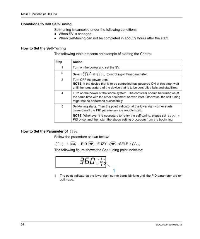
Conditions to Halt Self-Tuning
Self-tuning is canceled under the following conditions:When SV is changed.When Self-tuning can not be completed in about 9 hours after the start.
How to Set the Self-Tuning
The following table presents an example of starting the Control:
How to Set the Parameter of
Follow the procedure shown below:
→ →PID →FUZY→ → SELF→
The following figure shows the Self-tuning point indicator:
1 The point indicator at the lower right corner starts blinking until the PID parameter are re-optimized.
Step Action
1 Turn on the power and set the SV.
2 Select at (control algorithm) parameter.
3 Turn OFF the power once.NOTE: If the device that is to be controlled has powered ON at this step: wait until the temperature of the device that is to be controlled falls and stabilizes.
4 Turn on the power of the whole system. The controller should be turned on at the same time with the other equipment or even later. Otherwise, the self tuning might not be performed successfully.
5 Self-tuning starts. Then the point indicator at the lower right corner starts blinking until the PID parameters are re-optimized.
NOTE: Whenever it is necessary to re-try the self-tuning, please set = PID once, and then start the above setting procedure from the beginning.
1
54 EIO0000001300 09/2012
Main Functions of REG24
Alarm Function
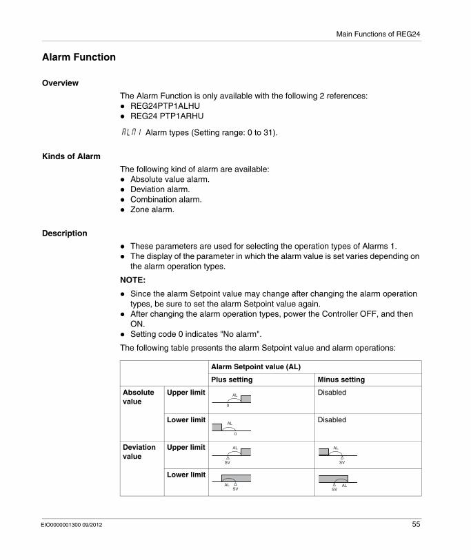
Overview
The Alarm Function is only available with the following 2 references:REG24PTP1ALHUREG24 PTP1ARHU
Alarm types (Setting range: 0 to 31).
Kinds of Alarm
The following kind of alarm are available:Absolute value alarm.Deviation alarm.Combination alarm.Zone alarm.
Description
These parameters are used for selecting the operation types of Alarms 1.The display of the parameter in which the alarm value is set varies depending on the alarm operation types.
NOTE:
Since the alarm Setpoint value may change after changing the alarm operation types, be sure to set the alarm Setpoint value again.After changing the alarm operation types, power the Controller OFF, and then ON.Setting code 0 indicates "No alarm".
The following table presents the alarm Setpoint value and alarm operations:
Alarm Setpoint value (AL)
Plus setting Minus setting
Absolute value
Upper limit Disabled
Lower limit Disabled
Deviation value
Upper limit
Lower limit
AL
0
AL
0
AL
SV
AL
SV
SVAL
SVAL
EIO0000001300 09/2012 55
Main Functions of REG24
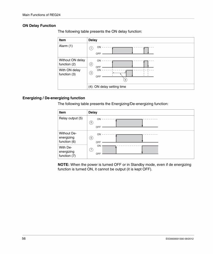
ON Delay Function
The following table presents the ON delay function:
Energizing / De-energizing function
The following table presents the Energizing/De-energizing function:
NOTE: When the power is turned OFF or in Standby mode, even if de energizing function is turned ON, it cannot be output (it is kept OFF).
Item Delay
Alarm (1)
Without ON delay function (2)
With ON delay function (3)
(4): ON delay setting time
ON
OFF
1
ON
OFFON
OFF
2
3
4
Item Delay
Relay output (5)
Without De-energizing function (6)
With De-energizing function (7)
ON
OFF
5
ON
OFFON
OFF
6
7
56 EIO0000001300 09/2012
Main Functions of REG24
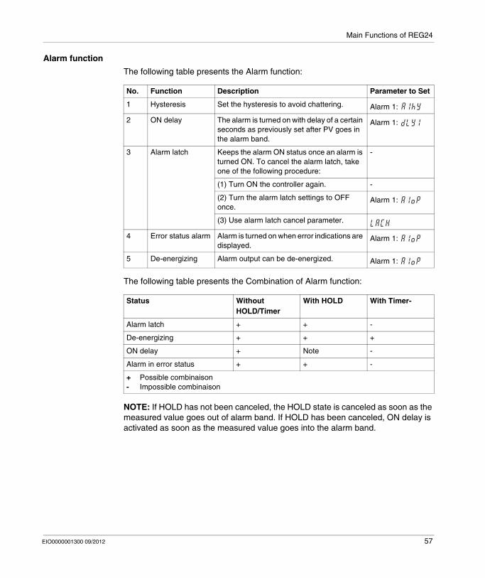
Alarm function
The following table presents the Alarm function:
The following table presents the Combination of Alarm function:
NOTE: If HOLD has not been canceled, the HOLD state is canceled as soon as the measured value goes out of alarm band. If HOLD has been canceled, ON delay is activated as soon as the measured value goes into the alarm band.
No. Function Description Parameter to Set
1 Hysteresis Set the hysteresis to avoid chattering. Alarm 1:
2 ON delay The alarm is turned on with delay of a certain seconds as previously set after PV goes in the alarm band.
Alarm 1:
3 Alarm latch Keeps the alarm ON status once an alarm is turned ON. To cancel the alarm latch, take one of the following procedure:
-
(1) Turn ON the controller again. -
(2) Turn the alarm latch settings to OFF once.
Alarm 1:
(3) Use alarm latch cancel parameter.
4 Error status alarm Alarm is turned on when error indications are displayed.
Alarm 1:
5 De-energizing Alarm output can be de-energized. Alarm 1:
Status Without HOLD/Timer
With HOLD With Timer-
Alarm latch + + -
De-energizing + + +
ON delay + Note -
Alarm in error status + + -
+ Possible combinaison- Impossible combinaison
EIO0000001300 09/2012 57
Main Functions of REG24
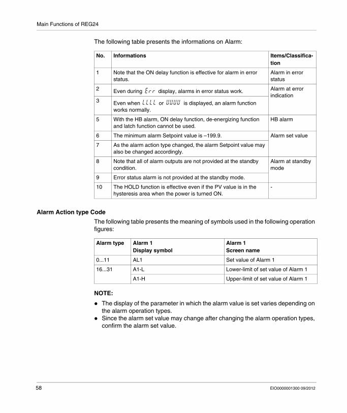
The following table presents the informations on Alarm:
Alarm Action type Code
The following table presents the meaning of symbols used in the following operation figures:
NOTE:
The display of the parameter in which the alarm value is set varies depending on the alarm operation types.Since the alarm set value may change after changing the alarm operation types, confirm the alarm set value.
No. Informations Items/Classifica-tion
1 Note that the ON delay function is effective for alarm in error status.
Alarm in error status
2 Even during display, alarms in error status work. Alarm at error indication
3 Even when or is displayed, an alarm function works normally.
5 With the HB alarm, ON delay function, de-energizing function and latch function cannot be used.
HB alarm
6 The minimum alarm Setpoint value is –199.9. Alarm set value
7 As the alarm action type changed, the alarm Setpoint value may also be changed accordingly.
8 Note that all of alarm outputs are not provided at the standby condition.
Alarm at standby mode
9 Error status alarm is not provided at the standby mode.
10 The HOLD function is effective even if the PV value is in the hysteresis area when the power is turned ON.
-
Alarm type Alarm 1Display symbol
Alarm 1Screen name
0...11 AL1 Set value of Alarm 1
16...31 A1-L Lower-limit of set value of Alarm 1
A1-H Upper-limit of set value of Alarm 1
58 EIO0000001300 09/2012
Main Functions of REG24
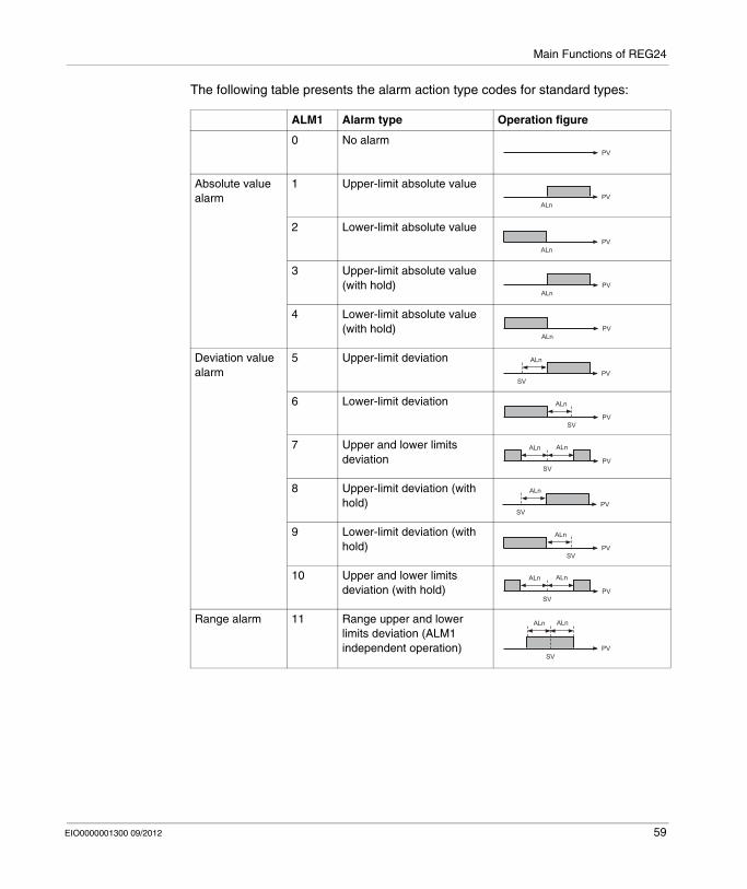
The following table presents the alarm action type codes for standard types:
ALM1 Alarm type Operation figure
0 No alarm
Absolute value alarm
1 Upper-limit absolute value
2 Lower-limit absolute value
3 Upper-limit absolute value (with hold)
4 Lower-limit absolute value (with hold)
Deviation value alarm
5 Upper-limit deviation
6 Lower-limit deviation
7 Upper and lower limits deviation
8 Upper-limit deviation (with hold)
9 Lower-limit deviation (with hold)
10 Upper and lower limits deviation (with hold)
Range alarm 11 Range upper and lower limits deviation (ALM1 independent operation)
PV
PVALn
PVALn
PVALn
PVALn
PV
ALn
SV
PV
ALn
SV
PV
ALnALn
SV
PV
ALn
SV
PV
ALn
SV
PV
ALnALn
SV
PV
ALn
SV
ALn
EIO0000001300 09/2012 59
Main Functions of REG24
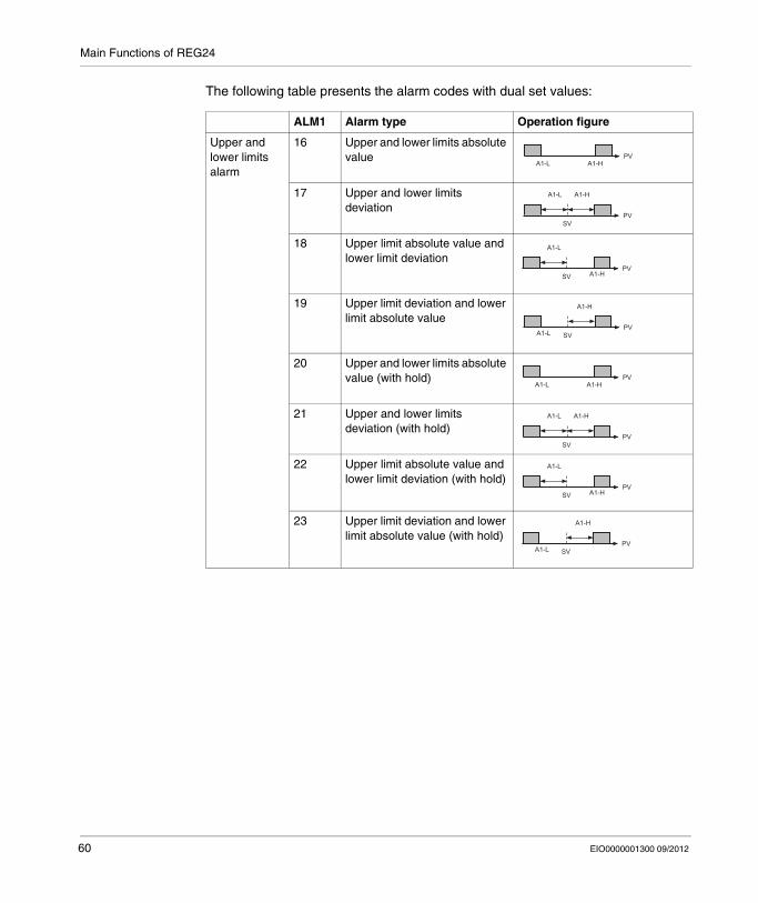
The following table presents the alarm codes with dual set values:
ALM1 Alarm type Operation figure
Upper and lower limits alarm
16 Upper and lower limits absolute value
17 Upper and lower limits deviation
18 Upper limit absolute value and lower limit deviation
19 Upper limit deviation and lower limit absolute value
20 Upper and lower limits absolute value (with hold)
21 Upper and lower limits deviation (with hold)
22 Upper limit absolute value and lower limit deviation (with hold)
23 Upper limit deviation and lower limit absolute value (with hold)
PVA1-L A1-H
PVSV
A1-L A1-H
PVSV
A1-L
A1-H
PVSV
A1-H
A1-L
PVA1-L A1-H
PVSV
A1-L A1-H
PVSV
A1-L
A1-H
PVSV
A1-H
A1-L
60 EIO0000001300 09/2012
Main Functions of REG24
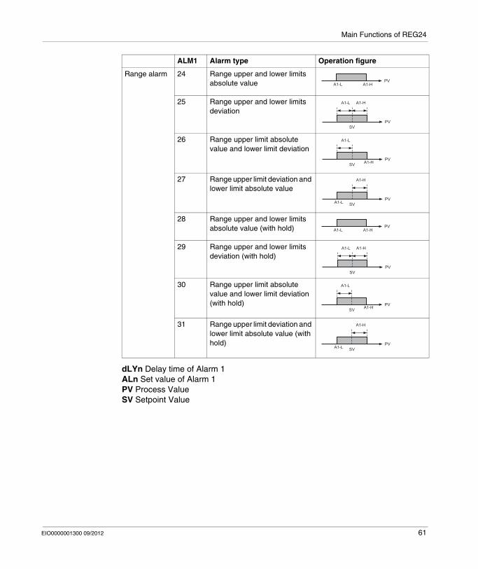
dLYn Delay time of Alarm 1ALn Set value of Alarm 1PV Process ValueSV Setpoint Value
Range alarm 24 Range upper and lower limits absolute value
25 Range upper and lower limits deviation
26 Range upper limit absolute value and lower limit deviation
27 Range upper limit deviation and lower limit absolute value
28 Range upper and lower limits absolute value (with hold)
29 Range upper and lower limits deviation (with hold)
30 Range upper limit absolute value and lower limit deviation (with hold)
31 Range upper limit deviation and lower limit absolute value (with hold)
ALM1 Alarm type Operation figure
PVA1-L A1-H
PVSV
A1-L A1-H
PVSV
A1-L
A1-H
PVSVA1-L
A1-H
PVA1-L A1-H
PVSV
A1-L A1-H
PVSV
A1-L
A1-H
PVSVA1-L
A1-H
EIO0000001300 09/2012 61
Main Functions of REG24
How to Cancel Alarm Latch
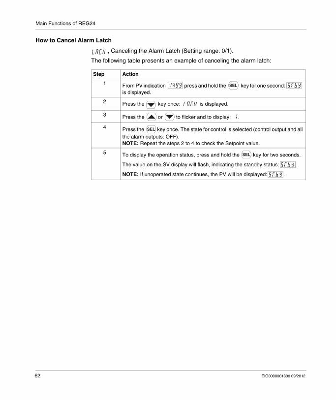
, Canceling the Alarm Latch (Setting range: 0/1).
The following table presents an example of canceling the alarm latch:
Step Action
1 From PV indication press and hold the key for one second: is displayed.
2 Press the key once: is displayed.
3 Press the or to flicker and to display: .
4 Press the key once. The state for control is selected (control output and all the alarm outputs: OFF). NOTE: Repeat the steps 2 to 4 to check the Setpoint value.
5 To display the operation status, press and hold the key for two seconds.
The value on the SV display will flash, indicating the standby status: .
NOTE: If unoperated state continues, the PV will be displayed: .
62 EIO0000001300 09/2012
Main Functions of REG24
Ramp/Soak
Overview
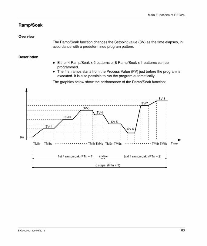
The Ramp/Soak function changes the Setpoint value (SV) as the time elapses, in accordance with a predetermined program pattern.
Description
Either 4 Ramp/Soak x 2 patterns or 8 Ramp/Soak x 1 patterns can be programmed.The first ramps starts from the Process Value (PV) just before the program is executed. It is also possible to run the program automatically.
The graphics below show the performance of the Ramp/Soak function:
SV-1
SV-2
SV-3SV-4
SV-5
SV-6
SV-7SV-8
TimeTM1r
PV
s8MTr8MTs5MTr5MTs4MTr4MTs1MT
k (PTn = 2)aos/pmar4dn2k (PTn = 1)aos/pmar4ts1
8 steps (PTn = 3)
and/orand/or
EIO0000001300 09/2012 63
Main Functions of REG24
Ramp/Soak Patterns
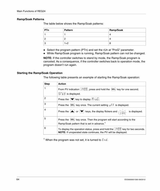
The table below shows the Ramp/Soak patterns:
Select the program pattern (PTn) and set the rUn at ”ProG” parameter.While Ramp/Soak program is running, Ramp/Soak pattern can not be changed.
NOTE: If the controller switches to stand by mode, the Ramp/Soak program is canceled. As a consequence, if the controller switches back to operation mode, the program doesn’t run again.
Starting the Ramp/Soak Operation
The following table presents an example of starting the Ramp/Soak operation:
1 When the program was not set, it is turned to .
PTn Pattern Ramp/Soak
1 1 4
2 2 4
3 1+2 8
Step Action
1 From PV indication , press and hold the key for one second;
is displayed.
2 Press the key to display .
3 Press the key once. The current setting is displayed.
4Press the or keys, the display flickers and is displayed.
5 Press the key once. Then the program will start according to the
Ramp/Soak pattern that is set in advance.1
6 To display the operation status, press and hold the key for two seconds.NOTE: If unoperated state continues, the PV will be displayed.
64 EIO0000001300 09/2012
Main Functions of REG24
Ramp/Soak Mode Setting Range 0 to 15
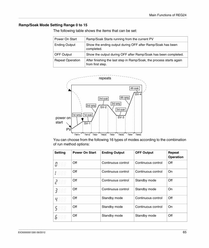
The following table shows the items that can be set:
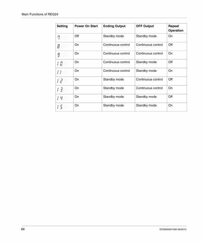
You can choose from the following 16 types of modes according to the combination of run method options:
Power On Start Ramp/Soak Starts running from the current PV
Ending Output Show the ending output during OFF after Ramp/Soak has been completed.
OFF Output Show the output during OFF after Ramp/Soak has been completed.
Repeat Operation After finishing the last step in Ramp/Soak, the process starts again from first step.
Setting Power On Start Ending Output OFF Output Repeat Operation
Off Continuous control Continuous control Off
Off Continuous control Continuous control On
Off Continuous control Standby mode Off
Off Continuous control Standby mode On
Off Standby mode Continuous control Off
Off Standby mode Continuous control On
Off Standby mode Standby mode Off
PV
SV-1
SV-2
SV-3
SV-4
1st ramppower on start
repeats
TM1r TM1S TM2r TM2S TM3r TM3S TM4r TM4S
2nd ramp
4th ramp
3rd ramp
2nd soak
3rd soak
4th soak
1st soak
EIO0000001300 09/2012 65
Main Functions of REG24
Off Standby mode Standby mode On
On Continuous control Continuous control Off
On Continuous control Continuous control On
On Continuous control Standby mode Off
On Continuous control Standby mode On
On Standby mode Continuous control Off
On Standby mode Continuous control On
On Standby mode Standby mode Off
On Standby mode Standby mode On
Setting Power On Start Ending Output OFF Output Repeat Operation
66 EIO0000001300 09/2012
Main Functions of REG24
Other Function: Anti-reset windup (Ar) and Output Convergence Value (bAL)
Overview
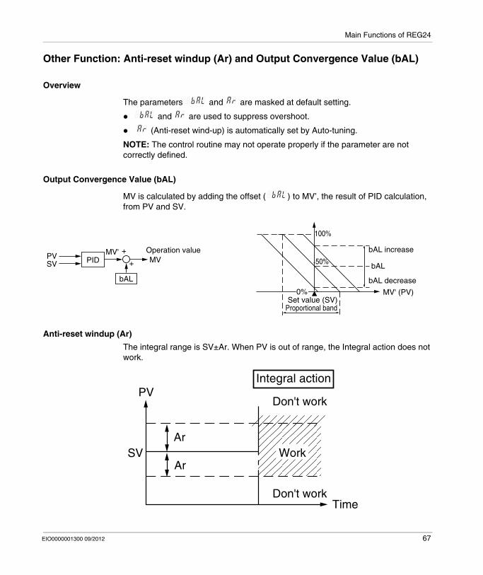
The parameters and are masked at default setting.
and are used to suppress overshoot.
(Anti-reset wind-up) is automatically set by Auto-tuning.
NOTE: The control routine may not operate properly if the parameter are not correctly defined.
Output Convergence Value (bAL)
MV is calculated by adding the offset ( ) to MV’, the result of PID calculation, from PV and SV.
Anti-reset windup (Ar)
The integral range is SV±Ar. When PV is out of range, the Integral action does not work.
bAL increase
bAL decrease
bAL50%
100%
PVSV PID
bAL
MV'MV
+
+
0%Set value (SV)
Operation value
Proportional band
MV' (PV)
Work
Time
Don't work
Integral action
Don't work
Ar
ArSV
PV
EIO0000001300 09/2012 67

Main Functions of REG24
68 EIO0000001300 09/2012

EIO0000001300 09/2012
II
Zelio Control
Appendices
EIO0000001300 09/2012
Appendices
69

Appendices
70 EIO0000001300 09/2012
EIO0000001300 09/2012
5
Zelio Control
REG24 Error Message
EIO0000001300 09/2012
REG24 Error Message
Error Indications
Display During Equipment Error
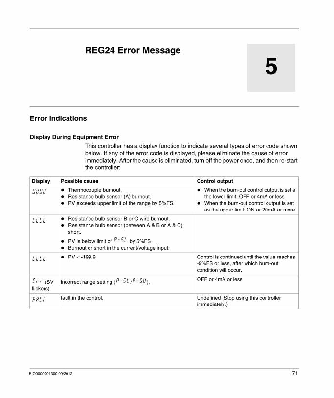
This controller has a display function to indicate several types of error code shown below. If any of the error code is displayed, please eliminate the cause of error immediately. After the cause is eliminated, turn off the power once, and then re-start the controller:
Display Possible cause Control output
Thermocouple burnout.Resistance bulb sensor (A) burnout.PV exceeds upper limit of the range by 5%FS.
When the burn-out control output is set a the lower limit: OFF or 4mA or lessWhen the burn-out control output is set as the upper limit: ON or 20mA or more
Resistance bulb sensor B or C wire burnout.Resistance bulb sensor (between A & B or A & C) short.
PV is below limit of by 5%FSBurnout or short in the current/voltage input.
PV < -199.9 Control is continued until the value reaches -5%FS or less, after which burn-out condition will occur.
(SV flickers)
incorrect range setting ( / ).OFF or 4mA or less
fault in the control. Undefined (Stop using this controller immediately.)
71

REG24 Error Message
72 EIO0000001300 09/2012
Zelio Control
Index
EIO0000001300 09/2012
CBA
IndexAAlarm Function of REG24, 55Auto-tuning (AT) of REG24, 50
BBasic Operations of REG24, 33
CConfiguration of REG24, 31
DDimensions and installation of REG24, 20Display and Controller References of REG24, 12
EElectrical Characteristics of REG24, 18Environmental Characteristics of REG24, 19
HHow to Configure REG24by Front Panel, 32
KKey Lock, 35
EIO0000001300 09/2012
MMain Characteristics of REG24, 15
OON/OFF Control of REG24, 48
PParameters List of REG24, 41
RRamp/Soak of REG24, 63
SSelf-Tuning of REG24, 53Setting the Temperature Controller, 37
WWiring of REG24, 27
73

Index
74 EIO0000001300 09/2012