Embed Size (px)
Citation preview

EUROPEAN LEADER
wood-cement blocks and floor slabs
Products catalogue
As by Guidelines of the Ministry of Public Works
PATENT No. 01287773

1
HD III block with insulation for external bearing walls, with high thermal insulation
HB block without polystyrene for internal bearing walls, increa-sing the thickness of the concrete increases the bearing capacity and acoustic insulation
For millennia, wood has been the most widely used raw material. This fact has contributed con-siderably to the development of wood-concrete formwork blocks that in many northern countries (Germany, Austria, Switzerland) have been suc-cessfully used for over 60 years. The wood is ground, then mineralized with the aid of the cement; this mix, via a block-making machine, is turned into solid blocks. In this way the porous structure, which is very important for the transpiration of the wall, is not destroyed. The formwork blocks are laid dry, thereby elimi-nating the various drawbacks caused by the use of mortar, subsequently filled with concrete, thus ensuring an excellent bearing structure. To facilitate the execution of the wall there is a series of special pieces such as the block to iso-late the floor slab, lintel for doors and windows,
which allow us to eliminate the cold bridges of our structure completely. This construction method with a single operation resolves the thermal insulation (utilizing double insulation with the wall of the block thicker to-ward the outside), the thermal inertia, noise and structure, taking full advantage of the characteri-stics of the concrete used for the filling. These characteristics provide excellent living comfort and a good percentage of savings on he-ating costs. By comparing the different construction mate-rials, the Isotex formwork block is the most com-plete and cost-effective method for making bea-ring walls.Additionally, thanks to its excellent workability, the material lends itself to making any type of construction.
Magnification of the wood mine-ralized with cement. The closed air pores are easily visible.
simple and complete construction system
Raw material: red firwood.
The first course is laid with mor-tar to level it.
Then all the other courses are laid dry.

2… with full respect for bio-building
Within Federal Germany, after passing the rela-tive tests, the formwork has been recognized as a biological material, and constant company and government controls ensure the best unchange-able quality. Besides the remarkable technical characteristi-cs, the Isotex formwork offers fast and easy in-stallation. You start by laying the first course with mortar so as to level it; the following courses are laid dry, and on reaching a height of approxi-mately 1.5 m the concrete is poured.
The remarkable lightness of the block, its dimen-sions (8 pieces per sq.m.), its easy workability (it can be cut with an ordinary saw) lets the operator make a wall effortlessly and fast. Considering the high cost of labour, the difficulty in finding skilled personnel, it is easy to deduce the benefits that can derive from using Isotex formworks from an economic and practical point of view.Isotex is perfectly on order according at the Gui-delines of Ministry of Public Works July 2011 cassonery blocks.
Building with 8 floors made entirely by utilizing the structu-re with concrete bearing walls obtained within the concrete blocks.
Social Housing Parma (2011-2012).
The concrete is cast every 6 courses in height. It must be vibrated.
Work of 110 dwellings made in 1985.

3
STANDARD BLOCKS
HB 20 HB 25/16 HB 30/19 HDIII 30/7 with graphiteKEY:
HB blocks without polystyrene: the first number is the thickness of the block, the second one the thickness of the concrete.
HD III blocks with insulation: the first number is the thickness of the block, the second one the thickness of the insulation.
Approximate permissible capacityR’cK ≥ 30 N/mm2 interp. h = 3,00 m
Thermal transmittance U of theplastered wall including wallliminaries W/m2 K
Thermal resistanceR (m2 K/W)
Acoustic insulation**(dB)(R’W) [D2mntw] RW [D2mntw]
•
•
•
•
110
46
310
34
0,79*
1,26*
[56****]
126
80
382
45
0,68*
1,47*
[55***]
151
85
445
35
0,34*
2,94*
[54***]
130
80
392
14
3
16
4,5
19
5,5
15
4
120
-
120
-
120
-
120
7
* The calculation of the thermal transmittance has been made according to the criteria of the UNI 10355 stan-dard and the EN ISO 6946 standard, using a three-di-mensional calculation program with finite elements va-lidated according to EN 10211/1 and on the basis of the thermal conductivity data obtained from experimental tests (see website).
PARTICULAR
PIECES
Thickness of block wall (cm)
Thickness of concrete (cm)
products range and ...
Concrete requirement I/ m2
Weight of blocks Kg/m2 (± 10%)
Weight of the wall filled withconcrete and not plastered Kg/m2
Fire rating Class REI (Loaded wall)
Thickness of polystyrene, graphite, cork (cm)
Blocks with corners as preferred (thicknesses25-30-33-38 cm)
Floor slab blockX = as preferredY = as preferredZ = x+y
Pillar block:33 cm section of concrete 25x38 cm38 cm section of concrete 30x38 cm44 cm section of concrete 33x39 cm
Half block forshoulder 44 cm
• For this block are not provide technical values as it does not meet current standards.
** Note: The test certificates can be requested from ISO-TEX or viewed on the WEBSITE. These are site testsvalues that have been processed according to the clues provided in the technical standards UNI EN ISO 140 and standards set UNI EN ISO 717.
X
Z

4
BLOCKS ON REQUESTSTANDAR BLOCKS
35
0,21*
4,76*
[54***]
130
88
400
27
0,28*
3,51*
[54***]
125
96
396
33
0,17*
5,73*
[54***]
122
136
410
32+32
0,56*
1,78*
[60****]
236
128
694
15+1515
4,5
16
5
15
5,5
120
14
120
12
120
18
120
-
15
4,5
15
4
HDIII 33/10 with graphite
35
0,27*
3,64*
[54**]
130
83
395
120
10
35
0,24*
4,16*
[54***]
130
88
400
120
14
*** Test performed in the laboratory with the standards UNI EN ISO 140-3:2006 and UNI EN ISO 717-1:2007
**** Test performed in the laboratory with the standards UNI EN ISO 140-3:2010 and UNI EN ISO 717-1:2007
FORMWORK BLOCKS ISOTEX COMPLY AT THE REQUIREMENT OF THE GUIDELINES APPROVED FROM THE MINISTRY OF PUBLIC WORK. (JULY 2011).
Pass block 30-33-38-44 cm Shoulder block 38-44 cm Corner block (UNI) 38-44 cmfor corner
Corner block (UNI) 30-33 cm for corners and shoulders
TECHNICAL PERFORMANCES
HDIII 38/14 HDIII 38/14 with graphite DIII 38/12 with cork DIII 44/18 with graphite HB 44/15-2

5hygrometric tests
EXCERPT OF CERTIFICATIONS THAT CAN BE FOUND IN FULL ON WEBSITE www.blocchiisotex.com

6fire rating tests with loaded walls and floors
EXCERPT OF CERTIFICATIONS THAT CAN BE FOUND IN FULL ON WEBSITE www.blocchiisotex.com
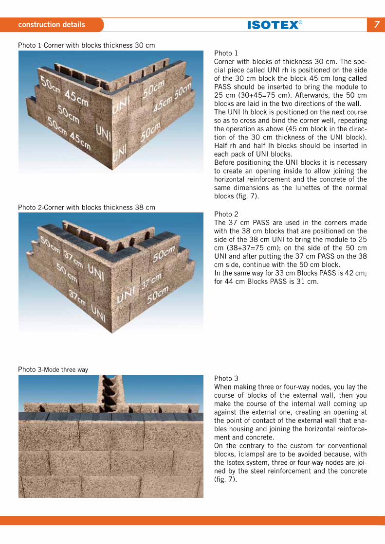
7construction details
Photo 1Corner with blocks of thickness 30 cm. The spe-cial piece called UNI rh is positioned on the side of the 30 cm block the block 45 cm long called PASS should be inserted to bring the module to 25 cm (30+45=75 cm). Afterwards, the 50 cm blocks are laid in the two directions of the wall.The UNI lh block is positioned on the next course so as to cross and bind the corner well, repeating the operation as above (45 cm block in the direc-tion of the 30 cm thickness of the UNI block). Half rh and half lh blocks should be inserted in each pack of UNI blocks.Before positioning the UNI blocks it is necessary to create an opening inside to allow joining the horizontal reinforcement and the concrete of the same dimensions as the lunettes of the normal blocks (fig. 7).
Photo 2The 37 cm PASS are used in the corners made with the 38 cm blocks that are positioned on the side of the 38 cm UNI to bring the module to 25 cm (38+37=75 cm); on the side of the 50 cm UNI and after putting the 37 cm PASS on the 38 cm side, continue with the 50 cm block.In the same way for 33 cm Blocks PASS is 42 cm; for 44 cm Blocks PASS is 31 cm.
Photo 3When making three or four-way nodes, you lay the course of blocks of the external wall, then you make the course of the internal wall coming up against the external one, creating an opening at the point of contact of the external wall that ena-bles housing and joining the horizontal reinforce-ment and concrete.On the contrary to the custom for conventional blocks, ìclampsî are to be avoided because, with the Isotex system, three or four-way nodes are joi-ned by the steel reinforcement and the concrete (fig. 7).
Photo 2-Corner with blocks thickness 38 cm
Photo 1-Corner with blocks thickness 30 cm
Photo 3-Mode three way

8
Examples of the standard reinforcement to be inserted in seismic zones, in any case, it must always be checkedby the designer of the structures.
construction details
FORMWORK BLOCKS ISOTEX COMPLY AT THE REQUIREMENT OF THE GUIDELINES APPROVED FROM THE MINISTRY OF PUBLIC WORK. (JULY 2011).
JUTTING REINFORCEMENTFOR JOINING
REINFORCED BELTAS PER STANDARDS AND BRACKETS
DIFFUSED VERTICALREINFORCEMENT
DIFFUSED HORIZONTALREINFORCEMENT
RESUMPTION FROMTHE FOUNDATION
MAGRONE
FOUNDATION
SUBSTRATE
20
0 C
M
50
CM
- - - - - - - -
20
0 C
M
FLOOR SLAB
RE
SU
MP
TIO
NS 50
CM
REINFORCEMENT OF WALL OF ISOTEX BLOCKSVERTICAL SECTION
Fig. 4 Fig. 5
Fig. 6 Fig. 73-WAY NODE REINFORCEMENT
HORIZONTAL SECTION
DIFFUSED HORIZONTAL REINFORCEMENT
DIFFUSED VERTICAL REINFORCEMENT
70 CM
HORIZONTAL REINFORCEMENT
HO
RIZ
ON
TAL
RE
INFO
RC
EM
EN
T
CORNER REINFORCEMENTHORIZONTAL SECTION
DIFFUSED VERTICAL REINFORCEMENT
DIFFUSED HORIZONTAL REINFORCEMENT
HORIZONTAL REINFORCEMENT VERTICAL
REINFORCEMENT100 CM
10
0 C
MH
OR
IZO
NTA
L R
EIN
FOR
CE
ME
NT
Stagger shoulders blocks with half shoulder are realized shoulders of doors and windows.
VERTICALREINFORCEMENT
VERTICALREINFORCEMENT
HORIZONTAL E
INFORCEMENT HORIZONTAL EINFORCEMENT
HD III 30/33
•HALF UNI(OBTAINED
FROM CUT UNI)
HD III 38 HD III 44
•SHOULDER
•HALF SHOULDER (OBTAINEDFROM CUT
SHOULDER)
•HALF SHOULDER (OBTAINEDFROM CUT
SHOULDER)
•SHOULDER•UNI

9instructions for laying blocks
When making the foundation it is necessary to in-sert the vertical reinforcement with a pitch of 25 cm (the pitch of the holes in the blocks) with a height of approximately 50 cm (fig. 6 page 8). The other possibility is to insert this vertical reinforcement with resins on the made foundation with the first course of blocks laid.The first course is laid on two layers of mortar posi-tioned only in correspondence with the walls of the blocks in order to be able to level it properly (it is recommended to use a spirit level);the layer of mortar on the entire width of the block is to be avoided. Mor-tar has definitely lower compression resistance than that of concrete *C 25/30. Position the corners flush and drop the plumb line. After setting the first course level, starting with the corner blocks (UNI), lay the following courses completely dry, taking care to slot the vertical and horizontal tapping properly, keeping the blocks tight to prevent noise and cold bridges.It is extremely important to stagger the next course of half block, using the special pieces as shown in photos 1-2-3-4 on pages 7-8 so as to obtain the gre-atest section of concrete inside the formworks and therefore have the wall capacity shown in the table on page 3-4.The blocks must always be laid with the lunette for joining the reinforcement and concrete upwards, the portion with insulation towards the outside, any cut-ting of the block necessary for making the wall to the size of the project must be done in the middle of the wall, keeping it in the same position on the following courses to prevent staggering the pillars inside the blocks with an ensuing reduction in capacity and dif-ficulty in filling the formworks with concrete. On each course the horizontal reinforcement will be inserted in the lunettes of the blocks (see details on page 8) up to a height of 6 courses, corresponding to 1.5 m.At this stage the walls will be filled completely with concrete, which can be done with a bucket or pump, taking care not to apply too much pressure that could shift the alignment of the blocks. The concrete must be rated S4-S5 (fluid and super-fluid) with a strength deriving from the calculation requirements and the particle size of the aggregate must be small (< 16 mm) so as to ensure the blocks are filled. It is es-sential to start filling the perimeter walls with con-crete remaining approximately one metre away from the corners and shoulders of doors and windows so that the concrete, passing through the lunettes of the blocks, applies less pressure and therefore does not move the formworks. On completing the perimeter walls you then pass on to fill the internal walls.In the first cast of 6 courses it is very important to
keep the level of concrete half way up the sixth course of blocks, insert the vertical reinforcement 2 m high at the same time as casting and vibrate this with a small needle to ensure the walls are filled complete-ly. If, when casting, the concrete on the block walls finishes it should be removed immediately so that, on hardening, it does not act as a shim; it is then possi-ble to continue to the height of the floor slab.The Guidelines standard requires inserting of 2 Ø 12 around doors and windows. The reinforcement must always be sized by the designer of the structures.
SOME RECOMMENDATIONS FOR CORRECTLY AP-PLING PLASTER AND COLOURED FINISHES ON WALLS MADE WITH “ISOTEX” FORMWORK BLOCKSAND FLOOR SLABS
The plaster must only be applied on dry surfaces. Therefore, do not do it on walls wet with rain, or due to insufficient ripening of the casting, or frost. Do not apply plaster with temperatures under 4°C as setting would be considerably slower and, as a result, the time for applying the finishes should be considerably modified. Proceed, a week in advance from applying the pla-ster, to close gaps greater than 2 cm between the blocks with mortar, so as to avoid considerable thick-nesses of plaster, such as to become potential points of cracking. The walls in the phase of construction must be made as vertical as possible and square; ap-plying thicknesses of plaster to be used as a means of straightening walls that are not vertical or are out of the perpendicular is not conceivable. A thickness greater than 2 cm leads to the formation of cracking; where it is necessary to apply thicknes-ses of plaster greater than 2 cm, it is fundamental for the application to be made in two layers, after ripe-ning for at least 28 days from the first layer. After these important preliminaries, we pass on to ap-ply the plaster, ready-mixed or conventional, conside-ring that the plaster, having the function of protecting the wall from the weather and from wear, must have as even a thickness as possible of 15 mm, moreover, bearing in mind that a lesser or greater thickness can facilitate cracking. It is important to put a fibreglass plaster net whe-re there are pillars, floor slab belts, flue liners and drains, making it protrude by approximately 10 cm on each side, inserting it half-way up the thickness of the plaster, therefore 7-8 mm from the base. The finish (fine or any other kind of mortar) must always be applied after a coat of adhesive with the plaster set, on average an interval is needed of at

10technical instructions
least 3-4 weeks; this time varies depending on the climatic conditions. For this type of finish (for the outside) that, to be suc-cessful, must be made with the undercoat (15 mm) fully ripened in order to avoid the formation of cracks, ISOTEX. not recommends the use of it precisely for the objective difficulty in checking the undercoat has fully ripened, and control that modality and time of application are fully respected. One solution more su-itable we can easily support, considering the positive experience had since 1995 on differents sites, consi-dering that in the last years most thermal performed blocks are used, causing in this way a bigger “stress” at the plaster, consists of applying a coloured finish top coat to thickness on the plaster undercoat (15 mm), after this has been levelled during application with a rule, after waiting 4-6 weeks since completing the undercoat, this solution does not require fine or any other kind of mortar. Remember, when the under-coat is applied and levelled off with the rule, to keep it as straight as possible and open with good solidity (not powdery). For the interiors it is recommended to leave an interval of 4-5 days between the base plaster and the fine mortar (or others) so that the base plaster has thoroughly dried before applying the fine mortar. ISOTEX. can supply information sheets on products for external finishes and their methods of application
PERMISSIBLE TOLERANCES OF BLOCKS
Length (b) and Width (d) +/-5mmHeight (G) +/-2mmHoles for concrete +5mm/-2mmHorizontal lunettes (e-f) +10mm/-3mm
ITEM OF SPECIFICATIONS
External and internal load-bearing walls made of for-mwork blocks Isotex in wood cement conglomerate having H-shaped conformation, density 510 kg +- 10% Kg/m3, dry-laid, staggered by half a block, ang cast in situ every 5/6 courses, with only one recess connection for concrete. The completed wall will be reinforced with steel bars both horizontally and ver-tically at a pitch of 25 cm and with casting concrete consistency of not less S4.Complete the range of blocks a number of particular pieces, such as: the shoulder block, corner block, flo-ors slab belt block, lintel block, pillar block.The blocks must have CE marking in accordance with ETA and the harmonized European standard EN 15498, the certifications of the thermal transmittan-ce values “U” according to European standard EN ISO 6496, UNI 10355 and EN 10211,characteristi-cs thermal dynamics and humidity according to DPR 59/09, acoustic tests according to UNI EN ISO 140 and UNI EN ISO 717, the evidence of fire resistence realized with charged walls according to EN 1365-1 and EN 13501-2 and certification of materials com-pliant with the requirements for green building issued by the departments concerned.
measurements in mm
The porous texture of the concrete, at the ribbing of the block joints, provides excellent diffusion of water vapour. The value of resistance to the passage of vapour in wood cement is µ = 5,9 (see certificate).
The arrangement of the concrete inside the blocks.
that anyhow must always ensure waterproofing for the wall. The plaster on the floor slabs has to be at least 15 mm thick, the plaster netting must be inserted half way up the thickness, the finish is applied after 4/5 days, 4/6 weeks for the painting. It should be noted that, ISOTEX srl, not being able to physically check compliance with the above-mentio-ned recommendations on a daily basis, for both the quality of the materials (plasters and coloured fini-shes) and the application times, cannot be held re-sponsible in any way for problems that may arise in the future. Regarding the features of S39 floor slab, which hasn’t concrete into the junction between the panels for termic reasons, but has joints that could cause, in these junction, the formation of micro-crazings. It’s re-commended as finish the employment of plasterboard panels along with a stream barrier.

11element in wood concrete for floor slab
The positive experience of over 60 years obtained with using wood-concrete blocks, ISOTEX has reali-zed a project that utilizes wood-concrete elements for the horizontal structures too. The goal, as we will see in the following documenta-tion, is to resolve, with a single operation, situations
such as completely eliminating all the relative noise and cold bridges for a construction, the fire rating, thermo-acoustic insulation, taking advantage in this sense of the greater inertia of this floor sla compa-red to several other solutions.
The bearing structure obtained inside the element, added to the overlapping of the floor slab (3 cm) on the wall, provides homogeneous insulation with complete elimination of the noise and cold bridges.
S39 for underground floor slabs and cover slabs Overlap of the floor slabs on the walls
PATENT No. 01287773

12structural use
DESIGN INSTRUCTIONS FORFLOOR SLAB OF THICKNESS S= 20 cm
Height of cast beam = 5 cm (0.016x2,500)
in factory and weight = 40 kg/sq.m.
Weight of panel produced in factory
= no. 4 x 20 = 80 + 40 = 120 kg/sq.m.
Volume of concrete for completion
= 0.02 + 0.015 (filling of elements
in wood) + 0.040 (concrete slab thickness
cm. 4) = 0.075 m3/sq.m.
Weight of concrete for completion
= 0.075 x 2,400 = 180 kg/sq.m.
Total own weight of completed floor slab
= 40 + 80 + 180 = 300 kg/sq.m
DESIGN INSTRUCTIONS FORFLOOR SLAB OF THICKNESS S= 25 cm
Height of cast beam = 5 cm (0,016x2.500)
in factory and weight = 40 kg/sq.m.
Weight of panel produced in factory
= no. 4 x 24 = 96 + 40 = 136 kg/sq.m.
Volume of concrete for completion
= 0.03 + 0.02 (filling of elements
in wood) + 0.040 (concrete slab thickness
cm. 4) = 0.09 m3/sq.m.
Weight of concrete for completion
= 0.09 x 2,400 = 216 kg/sq.m.
Total own weight of completed floor slab
= 40 + 96 + 216 = 352 kg/sq.m.
TOTAL BEARABLE LOAD BESIDES OWN WEIGHT TOTAL BEARABLE LOAD BESIDES OWN WEIGHT
The above table has been compiled on the basis of the usual criteria of resistance, considering mate-rials with the following characteristics:
concrete mix:......................C25/30 fyk = 25N/mm2
steeL:.................................B450c.
The above table has been compiled on the basis of the usual criteria of resistance, considering mate-rials with the following characteristics:
concrete mix:......................C25/30 fyk = 25N/mm2
steeL:.................................B450c.
S20 S25

13structural use
DESIGN INSTRUCTIONS FORFLOOR SLAB OF THICKNESS S = 25 cm + 5 cm
Height of cast beam = 5 cm (0.016x2,500)
in factory and weight = 40 kg/sq.m.
Weight of panel produced in factory
= no. 4 x 28 = 112 + 40 = 152 kg/sq.m.
Volume of concrete for completion
= 0.04 + 0.025 (filling of elements
in wood) + 0.040 (concrete slab thickness
cm. 4) = 0.105 m3/sq.m.
Weight of concrete for completion
= 0.105 x 2,400 = 252 kg/sq.m.
Total own weight of completed floor slab
=152 + 252 = 404 kg/sq.m.
DESIGN INSTRUCTIONS FORFLOOR SLAB OF THICKNESS S = 39 cm
Height of cast beam = 5 cm (0.016x2,500)
in factory and weight = 40 kg/sq.m.
Weight of panel produced in factory
=no. 4 x 39 = 156 + 40 = 196 kg/sq.m.
Volume of concrete for completion
= 0.03 (filling of elements in wood)
+ 0.040 (concrete slab thickness cm. 4)
= 0.07 m3/sq.m.
Weight of concrete for completion
= 0.07 x 2,400 = 168 kg/sq.m.
Total own weight of completed floor slab
= 40 + 156 + 168 = 364 kg/sq.m.
TOTAL BEARABLE LOAD BESIDES OWN WEIGHT TOTAL BEARABLE LOAD BESIDES OWN WEIGHT
The above table has been compiled on the basis of the usual criteria of resistance, considering mate-rials with the following characteristics:
concrete mix: ...................C25/30 fyk = 25N/mm2
steel:................................B450c.
The above table has been compiled on the basis of the usual criteria of resistance, considering mate-rials with the following characteristics:
concrete mix: ...................C25/30 fyk = 25N/mm2
steel:................................B450c.
Evaluations concerning the limits of deformability must be made on a case by case basis. If necessary the necessary precautions must be ta-ken to absorb the shearing forces (possibly adding brackets, eliminating hollow end tiles, etc…).
S25 + cm panel S39

14technical characteristics
VALUES OF THERMAL TRANSMITTANCE OF ISOTEX FLOOR SLABS
Key:R actual thermal resistance of the elementRlim thermal resistance limitRfin additional thermal resistance of any finishingR’ thermal resistance of floor slab finished with liminariesU’ thermal transmittance of floor slab finished with liminaries
* existing floor slabs calculated with (wood cement) = 0.11 W/mK ** new floor slabs calculated with (wood cement) = 0.103 W/mK
Thermal transmittance for floor slabs between floors Mass of Isotex floor slabs from 300 to 400 kg/m2
S 20*
S 25*
S 39 (8cm pse+grafite)**
R
0,846
0,921
3,407
Rlim
0,2
0,2
0,14
Rfin
0,542
0,542
0,542
R
1,588
1,663
4,089
U1 (W/m2K)
0,629723
0,601323
0,244557
Thermal transmittance of floor slabs for roofs Internal plaster + floor slab + concrete topping
R Rlim Rfin R U1 (W/m2K)
S 39 (8cm eps+graphite) ** 3,407024 0,14 - 3,547024 0,281926
S 39 (8cm eps+graphite) Winter Values Summer Values
PERIODIC THERMALTRASMITTENCE YlE [W/m2K] 0,003 0,003
ATTENUATION 0,011 0,012
LAG 25 h 36’ 25 h 28’
Additional thermal resistance of any finishing
thickness (cm) (W/mk) Rfin(m2K/W)
Lightened concrete substrate 8 0,28 0,286
Soundproofing 0,7 0,35 0,200
Concrete floor 1800 kg/m3 4 0,93 0,043
Ceramic floor 1,3 1 0,013
0,542
y
FLOOR SLABSFLOOR SLAB ELEMENT
THICKNESS AIRBORNE NOISE TESTS FOOTSTEP TESTS FIRE RATING
S20 (+ concrete bed)
S25 (+ concrete bed)
Rw=60 dB *
R1w=52 dB **
Ln, w2 53 dB with insulation*
Ln, w2 53 dB with insulation*
REI 240without plaster with loaded floor slab
* Floor packet with acoustic mat 8 mm thick**Floor slabs with concrete topping
REI 240without plaster with loaded floor slab

15For maximum living comfort
The “Isotex” floor slab enables making overhanging struc-tures, such as cornices and balconies, eliminating the cold bridge as a result.
The props supporting the panels can reach up to 1.80 m.
Intermediate and covering floor slabs Coibentation of the lateral side of the floor
FLOOR SLAB PROJECT
The lattice is made so as to assure the possibility of lifting and casting for completion in full safety, specifically:
1) in the lifting phase it is stressed by its own weight and considered suspended at two points set at L/4 from the ends;
2) in the casting phase it is considered set on supports at a centre distance of 170 cm and stressed by its own weight and by the weight of the fluid concrete. The supplementary reinforcement is inserted in the plant, in the quantity established by the planner of the struc-tures; it can be sized and tested with reference to the conclusive section. The cooperation between the completion casting and the beam cast in the plant is ensured by the lattice, which protrudes from the casting of the first phase by at least 4 cm; an adequate limitation of the tangential tensions of calculation makes it possible to avoid a specific reinforce-ment layout for shearing. There is the possibility of making transversal ribbing (per-pendicular to the framework of the floor slab); indeed, it is enough to contemplate using lowered hollow tile elements. For the operations of plastering, it is recommended to fol-low the directions given at pages 9 and 10 . The plaster
netting must be used, to be inserted approximately half way up the thickness of the undercoat, that must have as uniform a thickness as possible of 15 mm. In addition, it is necessary to wait 5-6 days between the undercoat and the finish of slaked lime or plaster.
Item Specifications floors slabs wood-cement ISOTEX
Floor slab “ISOTEX” on wood-cement conglomerate for horizontal or inclined structures with high thermal and acoustic insulation, made up of preassembled panels ele-ments of wood-cement, size 100 cm x (20-25-30-39), length up to mt. 6.5-7, with horizontal and vertical milling and elimination of thermal and acoustic bridges, comple-te with armor and cast concrete pack. The floor must be completed on site with supplementary armor extrados, ste-el net distribution and concrete cast for completion with collaborate 4-5cm slab. The floor panels Isotex have CE mark for the concrete beams in accordance with harmoni-zed European standard EN 15037-1, certifications of fire resistance (REI 240), thermal transmittance (DPR 59/09 and DM26 / 06/09), acoustic tests operates in accordance with the UNI EN ISO 140 and UNI EN ISO 717, structural testing, certification of materials comply with the require-ments for green building.

16Our documentation
Standards Catalogue
Free software for verifi-cation ISOTEX walls
Thermal Certifications
References Catalogue
Experimental tests andinterpretative report
Acustic Certifications

17certifications
EXCERPT OF CERTIFICATIONS THAT CAN BE FOUND IN FULL ON WEBSITE www.blocchi isotex.com
formwork blocks are in ISOTEXaccordance withUNI EN 15498
and european technical approval ETA 08/0023
The beams and blocks floor slab system ISOTEX
comply with the standardUNI EN 15037-1
MARKING CE EUROPEAN TECHNICAL APPROVEDETA 08/0023
MARKING CE FLOOR SLABSREQUIRED BY 01-01-2011
QUALITY CERTIFICATIONISO 9001:2008
BIO-BUILDING CERTIFICATION CREDITI LEED

18company
ALWAYS LOOKING FOR WINNING PERFORMANCES
Isotex is the major reality within the European scenario of wood-cement form-block manufacturing for the building industry, respecting the environ-ment and the new building standards.Over sixty year’s experience has led to achieving and consolidating leadership in the natural building material market.All this is thanks to a spirit distinguishing a successful brand at European le-vel: nothing is taken for granted, always looking for new ideas and horizons.
Center and productive plant

wood-cement blocks and floor slabs04/2015
Via D’Este, 5/7 - 5/842028 Poviglio (RE) ItalyTel. 0039 05229632Fax 0039 0522965500www.blocchiisotex.comsegreteria@[email protected]
UNI EN 15037-1UNI EN 15498ETA 08/0023
ISOTEX SRL


![Guidelines of Works Contracts [Compatibility Mode]](https://img.pdfslide.us/doc/110x75/577d23d81a28ab4e1e9aef64/guidelines-of-works-contracts-compatibility-mode.jpg)