Embed Size (px)
Citation preview
Progress in Engineering Application and Technology Vol. 1 No. 1 (2020) 173–190
© Universiti Tun Hussein Onn Malaysia Publisher’s Office
PEAT
Homepage: https://publisher.uthm.edu.my/periodicals/index.php/peat
e-ISSN : 0000-0000
*Corresponding author: [email protected] 2020 UTHM Publisher. All right reserved. publisher.uthm.edu.my/periodicals/index.php/peat
Artificial Intelligence Based Direct Torque
Control of Induction Motor Drive System
Sarinah Binti Alhamin1, Sim Sy Yi1,*, Chien Siong Kai1, Nor
Aira Zambri1, Farahiyah Mustafa1, Alvin Lim Meng Siang2 1 Faculty of Engineering Technology, Universiti Tun Hussein Onn Malaysia, 84600
Pagoh, Muar, Johor, Malaysia. 2 Faculty of Civil Engineering, Universiti Tun Hussein Onn Malaysia, 86400 Parit
Raja, Batu Pahat, Malaysia.
*Corresponding Author Designation DOI: https://doi.org/10.30880/peat.2020.01.01.020
Received 1 September 2020; Accepted 12 November 2020; Available online 02 December
2020
Abstract : In this project, a three-phase Induction motor (IM) under the direct torque
control (DTC) technique is studied. IM is known for its simple engines and its self-
starter feature but it always suffered a setback in the area of torque and speed control as it is a highly coupled nonlinear plant and proves to be most complex and expensive
speed drive. The application of direct torque control (DTC) is beneficial for fast
torque reaction in IM but provide high torque and ripples due to harmonic effects. Thus, the speed control of induction motor is important to achieve maximum torque
and efficiency. The aim of this study is to improve tracking performance of the
induction motor drive using artificial intelligence control system. A method for controlling induction motor drive is presented with Proportional-Integral (PI)
controller and Artificial Neural Networks (ANNs) for performance comparison.
MATLAB/SIMULINK software is used to develop a three-phase 2 pole-cage type
induction motor model. Also the performances of the two controllers have been verified in terms of its speed and torque responses. The ANN is trained so that the
speed of the drive tracks the reference speed. This study proved that the performance
and dynamics of the induction motor are enhanced using ANN controller as compared with PI controller.
Keywords: Neural Network , PI controller, Direct Torque Control
1. Introduction
Induction motors have much application in the industry because of their low maintenance and
robustness. In recent years, the control of the induction motor drive is an active research area and the
technology has further advances in this field and one of it is can be controlled with the help of PI
controller or articial intelligence based system such as Neural Network and Fuzzy with the use of direct
control technique.
Alhamin et al., Progress in Engineering Application and Technology Vol. 1 No. 1 (2020) p. 173-190
174
1.1 Direct Torque Control
DTC controls directly both the stator flux linkage and electromagnetic torque of the machine
simultaneously by the selection of optimum inverter switching modes. The use of a switching table for
voltage vector selection provides fast torque response, low inverter switching frequency and low
harmonic losses without the complex field orientation by restricting the flux and torque errors within
respective flux and torque hysteresis bands with the optimum selection being made. The DTC controller
abandons the stator current control philosophy by directly controls the flux itself and it consists of two
hysteresis comparators (flux and torque) to select the switching voltage vector in order to maintain flux
and torque between upper and lower limits. DTC has fast dynamic performance but provides high
ripples in torque due to the harmonics effect. Potential problems during start or low-speed operation
and during changes in torque command [1]. The DTC control technique is shown in Figure 1.
Figure 1: DTC Technique [1]
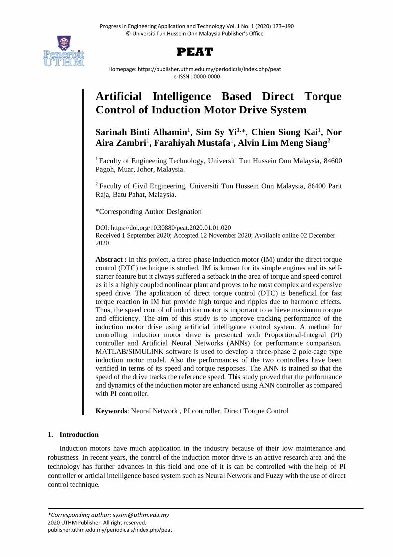
1.2 Proportional Integral Controller
The proportional integral (PI) controller is a feedback controller that drives the plant which is to be
controlled with a weighted sum of error and the integral of that value. Known to increase the order and
the type of the system by one. It also causes the steady state error to reduce to the zero, which is not the
case for proportional only control in general. Somehow, PI controller can never achieve perfect control,
that is, keep the speed of induction motor continuously at a desired set point value in the presence of
disturbance or set point change [2]. The basic block for PI controller is shown in Figure 2.
Figure 2: Basic PI system [4]
Alhamin et al., Progress in Engineering Application and Technology Vol. 1 No. 1 (2020) p. 173-190
175
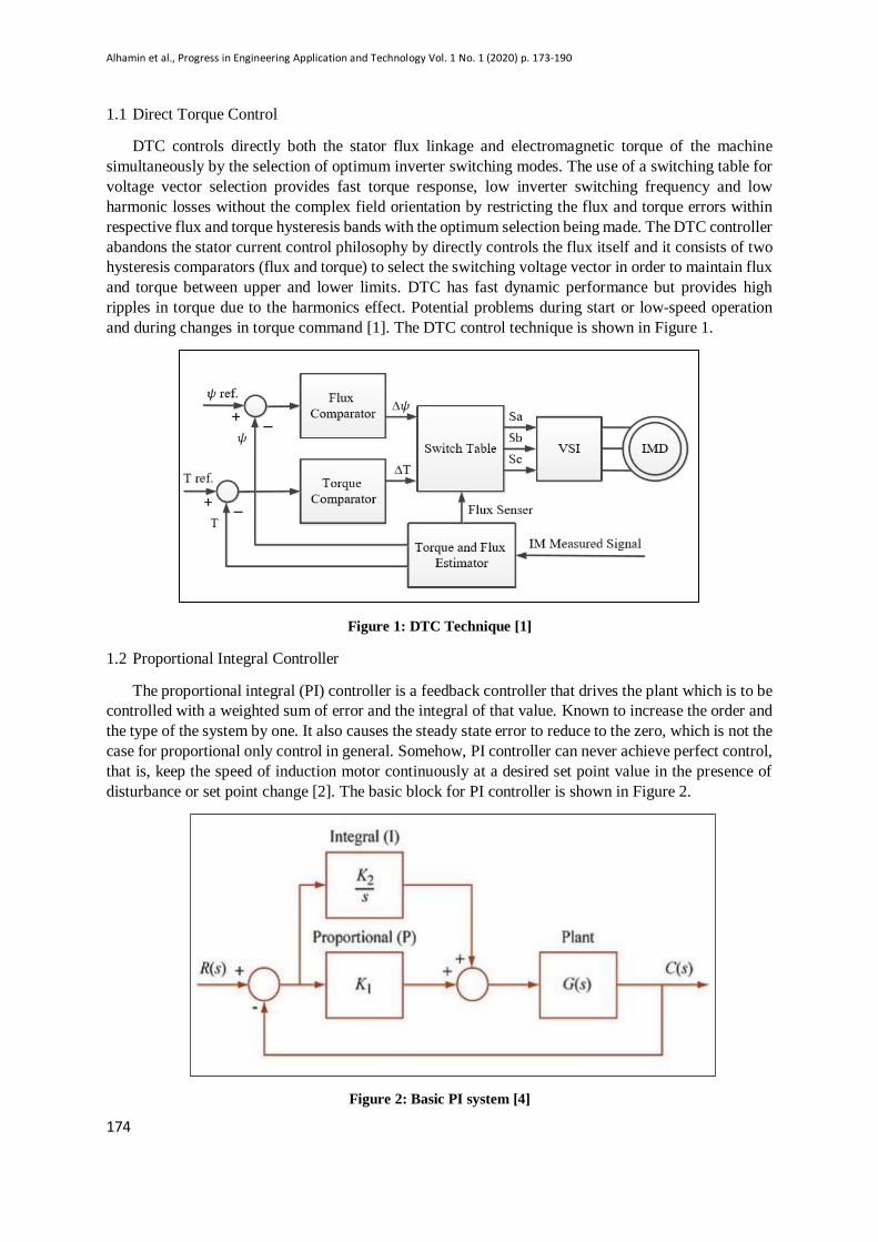
1.3 Artificial Neural Network (NN) Controller
NN is a mathematical model inspired by biological neural networks. It consists of an interconnected
group of artificial neurons, and it processes information using a connectionist approach to computation.
The control system for this drive is very similar to that of traditional control systems with a reference
input which is desired speed in, feedback (measured speed), the controller and the plant [10-11]. The
Controller is made of the artificial neurons connected in a network of 1 input layer, 3 hidden layers and
1output layer connected as a feed forward network and trained using the algorithm/coding. A sketch of
the neural network is shown in Figure 3. It has the special ability of learning which implies that it can
estimate the output of a system based on its experience on a set of previously trained data. Figure 4
shows the configuration topology used for the project known as an indirect scheme.
Figure 3: Neural Network Structure [5]
Figure 4: ANN Indirect scheme [9]
2. Research Methodology
This section will explain the methods used in developing and achieving the goals of this project.
This study is fully based on a mathematical block diagram built into Simulink MATLAB where
readings, graph and tabulation are taken and analyzed.
2.1 Simulink Model
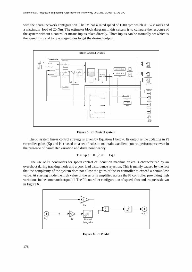
Figure 5 and 7 show the final design of the close-loop system based on the DTC scheme. Figure 5
is the PI control system where speed, torque and flux are controlled using the respective method. The
PI controller is shown in Figure 6. Meanwhile Figure 7 is the improved version where speed controller
of PI scheme is replaced by ANN controller. The PI controller for speed is replaced with ANN controller
to use as the input of the feedback system to the torque controller. This means that both speed and torque
controller has the ANN characteristic as input to the IM that made changes to the whole system response
Alhamin et al., Progress in Engineering Application and Technology Vol. 1 No. 1 (2020) p. 173-190
176
with the neural network configuration. The IM has a rated speed of 1500 rpm which is 157.8 rad/s and
a maximum load of 20 Nm. The estimator block diagram in this system is to compare the response of
the system without a controller means inputs taken directly. Three inputs can be manually set which is
the speed, flux and torque magnitudes to get the desired output.
Figure 5: PI Control system
The PI system linear control strategy is given by Equation 1 below. Its output is the updating in PI
controller gains (Kp and Ki) based on a set of rules to maintain excellent control performance even in
the presence of parameter variation and drive nonlinearity.
T = Kp e + Ki ∫e dt Eq.1
The use of PI controllers for speed control of induction machine drives is characterized by an
overshoot during tracking mode and a poor load disturbance rejection. This is mainly caused by the fact
that the complexity of the system does not allow the gains of the PI controller to exceed a certain low
value. At starting mode the high value of the error is amplified across the PI controller provoking high
variations in the command torque[4]. The PI controller configuration of speed, flux and troque is shown
in Figure 6.
Figure 6: PI Model
Alhamin et al., Progress in Engineering Application and Technology Vol. 1 No. 1 (2020) p. 173-190
177
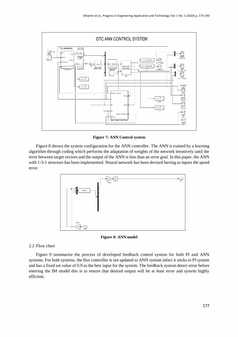
Figure 7: ANN Control system
Figure 8 shown the system configuration for the ANN controller. The ANN is trained by a learning
algorithm through coding which performs the adaptation of weights of the network iteratively until the
error between target vectors and the output of the ANN is less than an error goal. In this paper, the ANN
with 1-3-1 structure has been implemented. Neural network has been devised having as inputs the speed
error.
Figure 8: ANN model
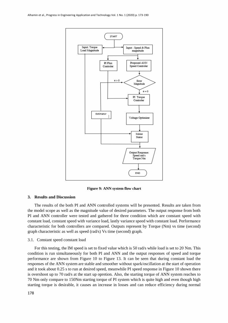
2.2 Flow chart
Figure 9 summarize the process of developed feedback control system for both PI and ANN
systems. For both systems, the flux controller is not updated to ANN system infact it sticks to PI system
and has a fixed set value of 0.9 as the best input for the system. The feedback system detect error before
entering the IM model this is to ensure that desired output will be at least error and system highly
efficient.
Alhamin et al., Progress in Engineering Application and Technology Vol. 1 No. 1 (2020) p. 173-190
178
Figure 9: ANN system flow chart
3. Results and Discussion
The results of the both PI and ANN controlled systems will be presented. Results are taken from
the model scope as well as the magnitude value of desired parameters. The output response from both
PI and ANN controller were tested and gathered for three condition which are constant speed with
constant load, constant speed with variance load, lastly variance speed with constant load. Performance
characteristic for both controllers are compared. Outputs represent by Torque (Nm) vs time (second)
graph characteristic as well as speed (rad/s) Vs time (second) graph.
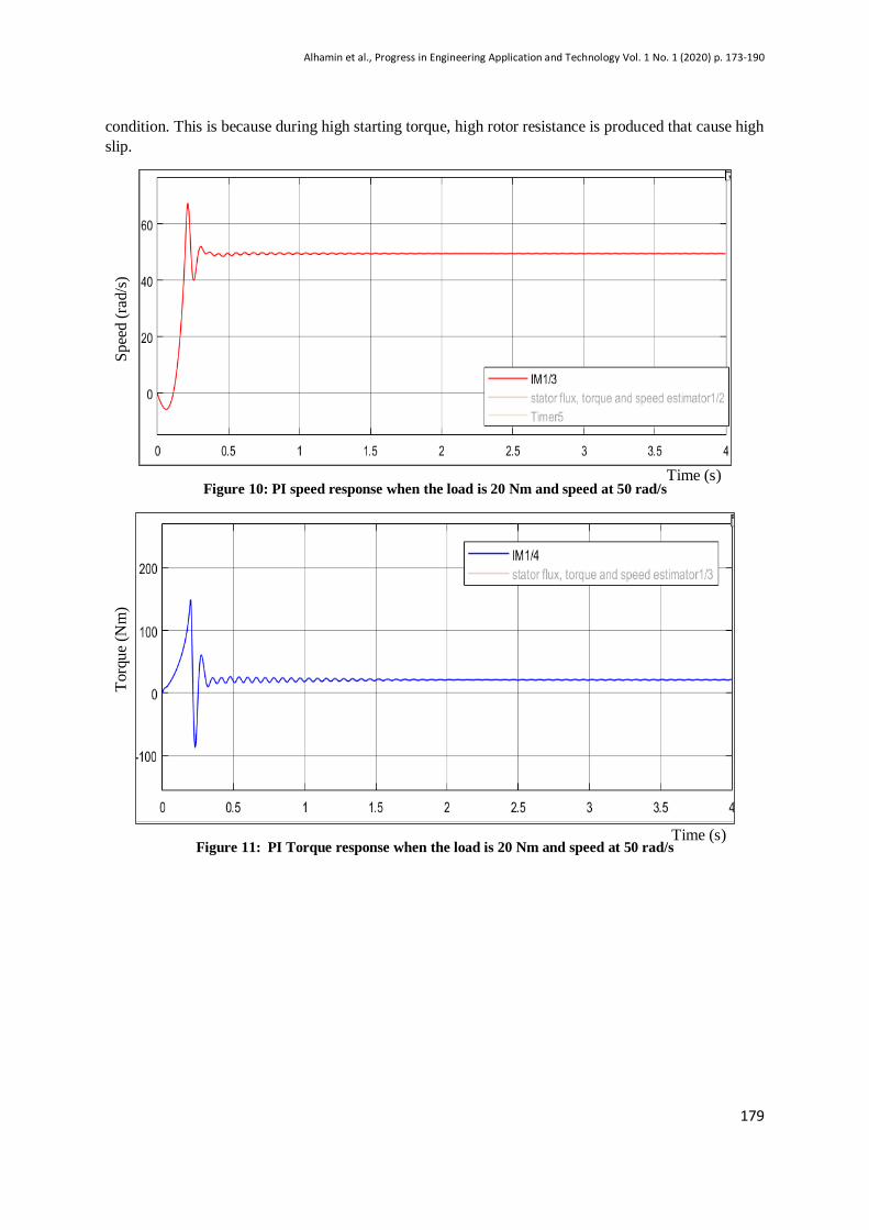
3.1. Constant speed constant load
For this testing, the IM speed is set to fixed value which is 50 rad/s while load is set to 20 Nm. This
condition is run simultaneously for both PI and ANN and the output responses of speed and torque
performance are shown from Figure 10 to Figure 13. It can be seen that during constant load the
responses of the ANN system are stable and smoother without spark/oscillation at the start of operation
and it took about 0.25 s to run at desired speed, meanwhile PI speed response in Figure 10 shown there
is overshoot up to 70 rad/s at the start up opretion. Also, the starting torque of ANN system reaches to
70 Nm only compare to 150Nm starting torque of PI system which is quite high and even though high
starting torque is desirable, it causes an increase in losses and can reduce efficiency during normal
Alhamin et al., Progress in Engineering Application and Technology Vol. 1 No. 1 (2020) p. 173-190
179
condition. This is because during high starting torque, high rotor resistance is produced that cause high
slip.
Figure 10: PI speed response when the load is 20 Nm and speed at 50 rad/s
Figure 11: PI Torque response when the load is 20 Nm and speed at 50 rad/s
Sp
eed (
rad/s
) T
orq
ue
(Nm
)
Time (s)
Time (s)
Alhamin et al., Progress in Engineering Application and Technology Vol. 1 No. 1 (2020) p. 173-190
180
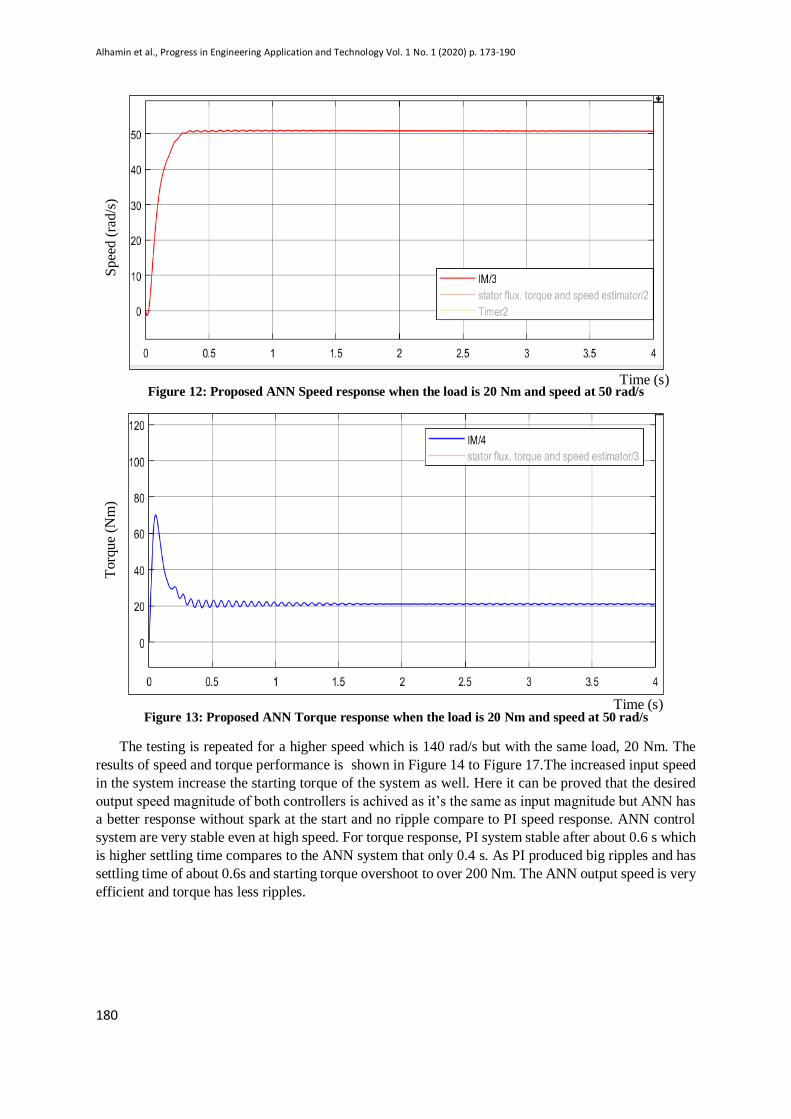
Figure 12: Proposed ANN Speed response when the load is 20 Nm and speed at 50 rad/s
Figure 13: Proposed ANN Torque response when the load is 20 Nm and speed at 50 rad/s
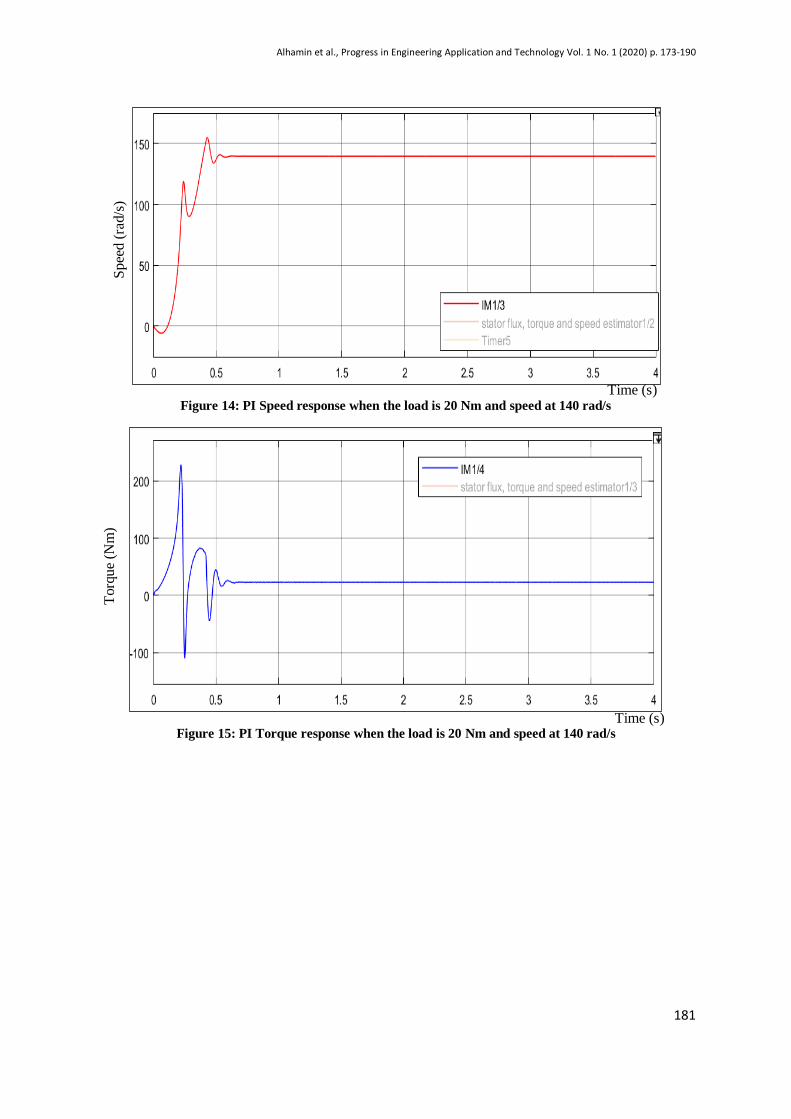
The testing is repeated for a higher speed which is 140 rad/s but with the same load, 20 Nm. The
results of speed and torque performance is shown in Figure 14 to Figure 17.The increased input speed
in the system increase the starting torque of the system as well. Here it can be proved that the desired
output speed magnitude of both controllers is achived as it’s the same as input magnitude but ANN has
a better response without spark at the start and no ripple compare to PI speed response. ANN control
system are very stable even at high speed. For torque response, PI system stable after about 0.6 s which
is higher settling time compares to the ANN system that only 0.4 s. As PI produced big ripples and has
settling time of about 0.6s and starting torque overshoot to over 200 Nm. The ANN output speed is very
efficient and torque has less ripples.
Time (s)
Sp
eed (
rad/s
) T
orq
ue
(Nm
)
Time (s)
Alhamin et al., Progress in Engineering Application and Technology Vol. 1 No. 1 (2020) p. 173-190
181
Figure 14: PI Speed response when the load is 20 Nm and speed at 140 rad/s
Figure 15: PI Torque response when the load is 20 Nm and speed at 140 rad/s
Sp
eed (
rad/s
)
Time (s)
Torq
ue
(Nm
)
Time (s)
Alhamin et al., Progress in Engineering Application and Technology Vol. 1 No. 1 (2020) p. 173-190
182
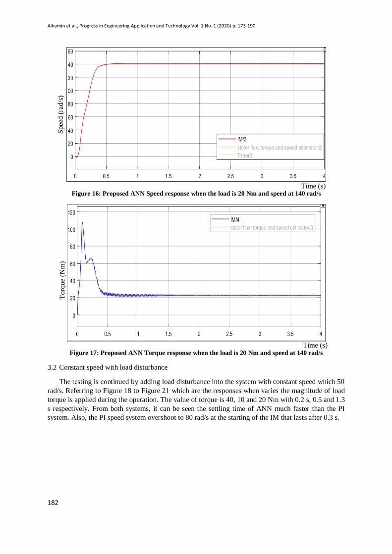
Figure 16: Proposed ANN Speed response when the load is 20 Nm and speed at 140 rad/s
Figure 17: Proposed ANN Torque response when the load is 20 Nm and speed at 140 rad/s
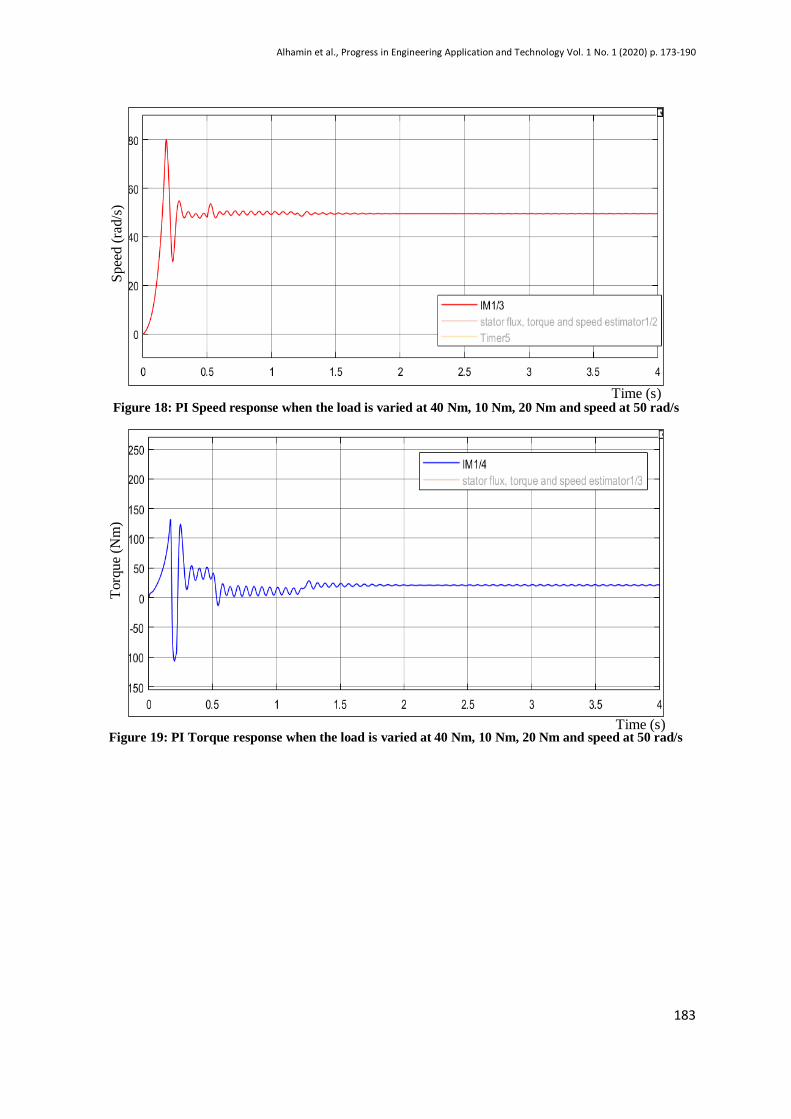
3.2 Constant speed with load disturbance
The testing is continued by adding load disturbance into the system with constant speed which 50
rad/s. Referring to Figure 18 to Figure 21 which are the responses when varies the magnitude of load
torque is applied during the operation. The value of torque is 40, 10 and 20 Nm with 0.2 s, 0.5 and 1.3
s respectively. From both systems, it can be seen the settling time of ANN much faster than the PI
system. Also, the PI speed system overshoot to 80 rad/s at the starting of the IM that lasts after 0.3 s.
Time (s)
Time (s)
Torq
ue
(Nm
) S
pee
d (
rad/s
)
Alhamin et al., Progress in Engineering Application and Technology Vol. 1 No. 1 (2020) p. 173-190
183
Figure 18: PI Speed response when the load is varied at 40 Nm, 10 Nm, 20 Nm and speed at 50 rad/s
Figure 19: PI Torque response when the load is varied at 40 Nm, 10 Nm, 20 Nm and speed at 50 rad/s
Sp
eed (
rad/s
) T
orq
ue
(Nm
)
Time (s)
Time (s)
Alhamin et al., Progress in Engineering Application and Technology Vol. 1 No. 1 (2020) p. 173-190
184
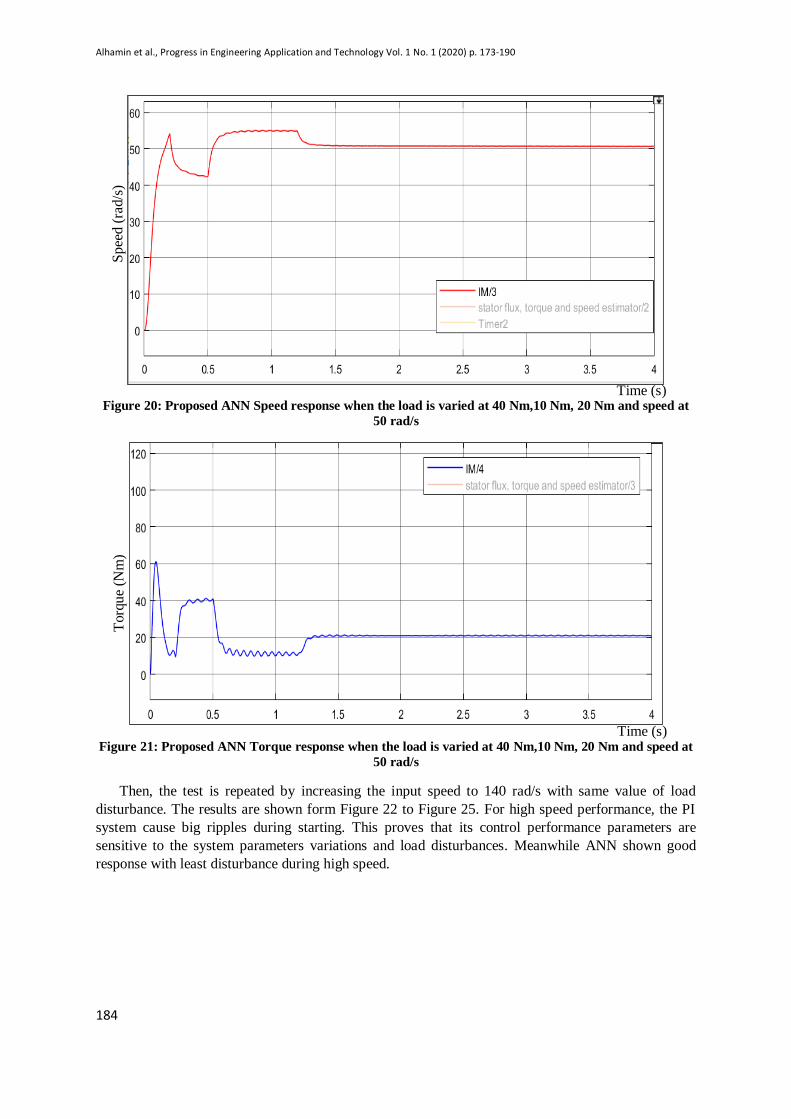
Figure 20: Proposed ANN Speed response when the load is varied at 40 Nm,10 Nm, 20 Nm and speed at
50 rad/s
Figure 21: Proposed ANN Torque response when the load is varied at 40 Nm,10 Nm, 20 Nm and speed at
50 rad/s
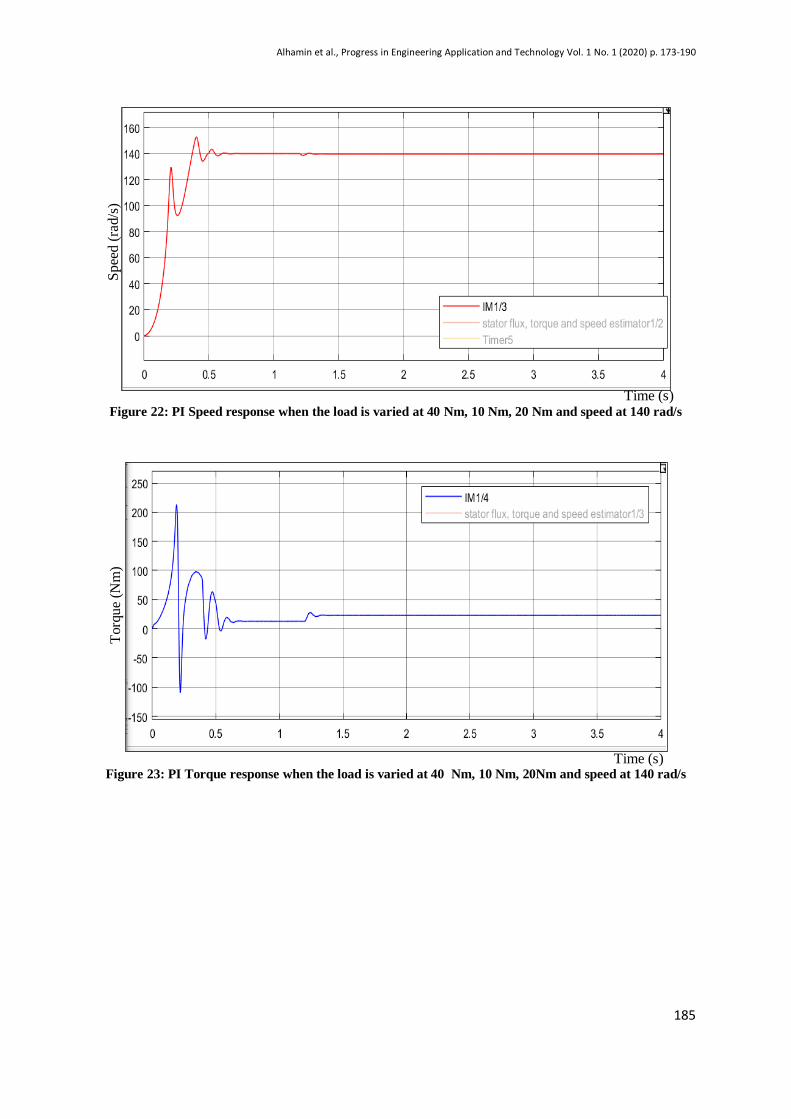
Then, the test is repeated by increasing the input speed to 140 rad/s with same value of load
disturbance. The results are shown form Figure 22 to Figure 25. For high speed performance, the PI
system cause big ripples during starting. This proves that its control performance parameters are
sensitive to the system parameters variations and load disturbances. Meanwhile ANN shown good
response with least disturbance during high speed.
Time (s)
Time (s)
Sp
eed (
rad/s
) T
orq
ue
(Nm
)
Alhamin et al., Progress in Engineering Application and Technology Vol. 1 No. 1 (2020) p. 173-190
185
Figure 22: PI Speed response when the load is varied at 40 Nm, 10 Nm, 20 Nm and speed at 140 rad/s
Figure 23: PI Torque response when the load is varied at 40 Nm, 10 Nm, 20Nm and speed at 140 rad/s
Sp
eed (
rad/s
) T
orq
ue
(Nm
)
Time (s)
Time (s)
Alhamin et al., Progress in Engineering Application and Technology Vol. 1 No. 1 (2020) p. 173-190
186
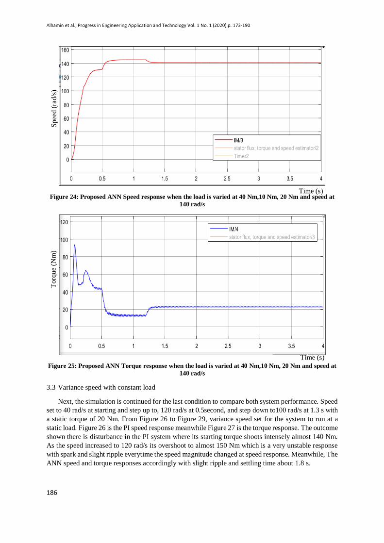
Figure 24: Proposed ANN Speed response when the load is varied at 40 Nm,10 Nm, 20 Nm and speed at
140 rad/s
Figure 25: Proposed ANN Torque response when the load is varied at 40 Nm,10 Nm, 20 Nm and speed at
140 rad/s
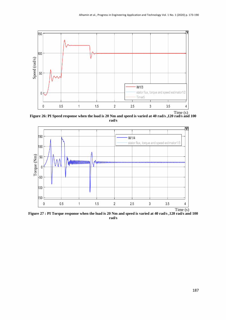
3.3 Variance speed with constant load
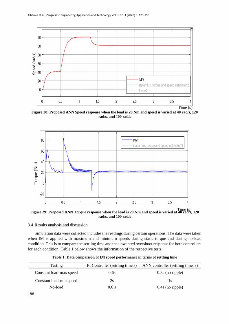
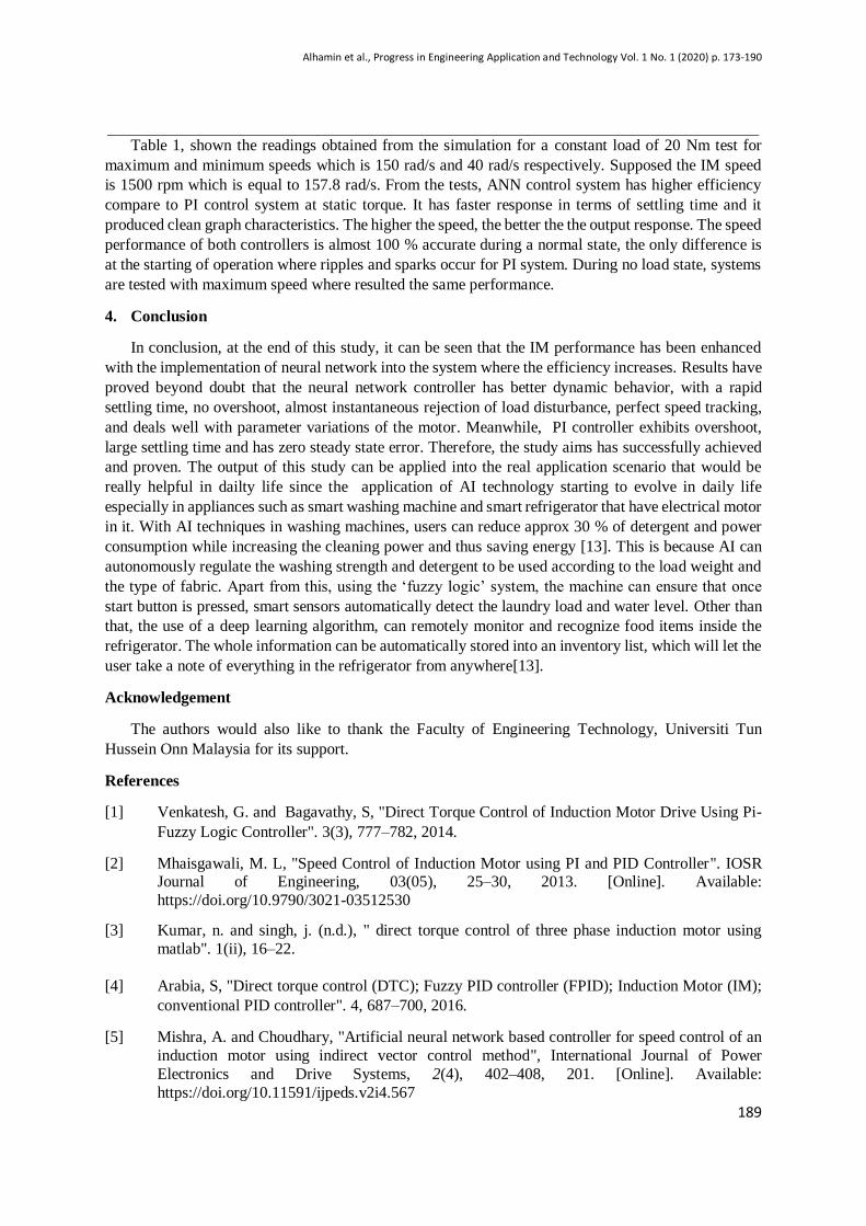
Next, the simulation is continued for the last condition to compare both system performance. Speed
set to 40 rad/s at starting and step up to, 120 rad/s at 0.5second, and step down to100 rad/s at 1.3 s with
a static torque of 20 Nm. From Figure 26 to Figure 29, variance speed set for the system to run at a
static load. Figure 26 is the PI speed response meanwhile Figure 27 is the torque response. The outcome
shown there is disturbance in the PI system where its starting torque shoots intensely almost 140 Nm.
As the speed increased to 120 rad/s its overshoot to almost 150 Nm which is a very unstable response
with spark and slight ripple everytime the speed magnitude changed at speed response. Meanwhile, The
ANN speed and torque responses accordingly with slight ripple and settling time about 1.8 s.
Torq
ue
(Nm
) S
pee
d (
rad/s
)
Time (s)
Time (s)
Alhamin et al., Progress in Engineering Application and Technology Vol. 1 No. 1 (2020) p. 173-190
187
Figure 26: PI Speed response when the load is 20 Nm and speed is varied at 40 rad/s ,120 rad/s and 100
rad/s
Figure 27 : PI Torque response when the load is 20 Nm and speed is varied at 40 rad/s ,120 rad/s and 100
rad/s
Torq
ue
(Nm
) S
pee
d (
rad/s
)
Time (s)
Time (s)
Alhamin et al., Progress in Engineering Application and Technology Vol. 1 No. 1 (2020) p. 173-190
188
Figure 28: Proposed ANN Speed response when the load is 20 Nm and speed is varied at 40 rad/s, 120
rad/s, and 100 rad/s
Figure 29: Proposed ANN Torque response when the load is 20 Nm and speed is varied at 40 rad/s, 120
rad/s, and 100 rad/s
3.4 Results analysis and discussion
Simulation data were collected includes the readings during certain operations. The data were taken
when IM is applied with maximum and minimum speeds during static torque and during no-load
condition. This is to compare the settling time and the unwanted overshoot response for both controllers
for each condition. Table 1 below shows the information of the respective tests.
Table 1: Data comparison of IM speed performance in terms of settling time
Testing PI Controller (settling time,s) ANN controller (settling time, s)
Constant load-max speed 0.6s 0.3s (no ripple)
Constant load-min speed 2s 1s
No-load 0.6 s 0.4s (no ripple)
Torq
ue
(Nm
) S
pee
d (
rad/s
)
Time (s)
Time (s)
Alhamin et al., Progress in Engineering Application and Technology Vol. 1 No. 1 (2020) p. 173-190
189
Table 1, shown the readings obtained from the simulation for a constant load of 20 Nm test for
maximum and minimum speeds which is 150 rad/s and 40 rad/s respectively. Supposed the IM speed
is 1500 rpm which is equal to 157.8 rad/s. From the tests, ANN control system has higher efficiency
compare to PI control system at static torque. It has faster response in terms of settling time and it
produced clean graph characteristics. The higher the speed, the better the the output response. The speed
performance of both controllers is almost 100 % accurate during a normal state, the only difference is
at the starting of operation where ripples and sparks occur for PI system. During no load state, systems
are tested with maximum speed where resulted the same performance.
4. Conclusion
In conclusion, at the end of this study, it can be seen that the IM performance has been enhanced
with the implementation of neural network into the system where the efficiency increases. Results have
proved beyond doubt that the neural network controller has better dynamic behavior, with a rapid
settling time, no overshoot, almost instantaneous rejection of load disturbance, perfect speed tracking,
and deals well with parameter variations of the motor. Meanwhile, PI controller exhibits overshoot,
large settling time and has zero steady state error. Therefore, the study aims has successfully achieved
and proven. The output of this study can be applied into the real application scenario that would be
really helpful in dailty life since the application of AI technology starting to evolve in daily life
especially in appliances such as smart washing machine and smart refrigerator that have electrical motor
in it. With AI techniques in washing machines, users can reduce approx 30 % of detergent and power
consumption while increasing the cleaning power and thus saving energy [13]. This is because AI can
autonomously regulate the washing strength and detergent to be used according to the load weight and
the type of fabric. Apart from this, using the ‘fuzzy logic’ system, the machine can ensure that once
start button is pressed, smart sensors automatically detect the laundry load and water level. Other than
that, the use of a deep learning algorithm, can remotely monitor and recognize food items inside the
refrigerator. The whole information can be automatically stored into an inventory list, which will let the
user take a note of everything in the refrigerator from anywhere[13].
Acknowledgement
The authors would also like to thank the Faculty of Engineering Technology, Universiti Tun
Hussein Onn Malaysia for its support.
References
[1] Venkatesh, G. and Bagavathy, S, "Direct Torque Control of Induction Motor Drive Using Pi-
Fuzzy Logic Controller". 3(3), 777–782, 2014.
[2] Mhaisgawali, M. L, "Speed Control of Induction Motor using PI and PID Controller". IOSR Journal of Engineering, 03(05), 25–30, 2013. [Online]. Available:
https://doi.org/10.9790/3021-03512530
[3] Kumar, n. and singh, j. (n.d.), " direct torque control of three phase induction motor using
matlab". 1(ii), 16–22.
[4] Arabia, S, "Direct torque control (DTC); Fuzzy PID controller (FPID); Induction Motor (IM);
conventional PID controller". 4, 687–700, 2016.
[5] Mishra, A. and Choudhary, "Artificial neural network based controller for speed control of an
induction motor using indirect vector control method", International Journal of Power
Electronics and Drive Systems, 2(4), 402–408, 201. [Online]. Available:
https://doi.org/10.11591/ijpeds.v2i4.567

Alhamin et al., Progress in Engineering Application and Technology Vol. 1 No. 1 (2020) p. 173-190
190
[6] Saidas, M. G. and Hima, T, " Steady state Direct Torque Control of induction motor by using
Anti- windup PI controller". 1336–1340, 2015.
[7] Stephen, C., Amudha, A., Balachander, K., Ramkumar, M. S., Emayavaramban, G., & Manoor,
I. R. V, "Direct Torque Control of Induction Motor Using SVM Techniques".(1), 196–202,
2019.
[8] Abdullah, A. N., Ali, M. H., and Ali, M. H, "Direct torque control of IM using PID controller"
10(1), 617–625, 2020. [Online]. Available: httpdoi.org/10.11591/ijece.v10i1.pp617-625
[9] B. O. Omijeh and D.C.Idoniboyeobu, "Artificial Neural Network Based Induction Motor Speed
Controller". International Journal of Electronics Communication and Computer Engineering,
Volume 6, Issue 1, ISSN (Online): 2249–071X, ISSN (Print): 2278–4209
[10] F.L. Lewis and Shuzhi Sam Ge ," Neural networks in feedback control system ", Mechanical
Engineer’s Handbook, 2015
[11] Omijeh B. O, "Circuit Analysis and Simulation (With Matlab and Tina Apps)", First Edition,
Joint Heirs Publications Nig. LTD, 2009.
[12] Mishra and Choudhary P.,"Artificial Neural Network Based Controller for Speed Control of an
Induction Motor Using Indirect Vector Method", International Journal of Power Electronics
and Drive System (IJPEDS), Vol.2, pp. 402-408, 2012
[13] Shubhada Khokale, " Digitizing Homes: Making Everyday Appliances Smarter with IoT and
AI". 2018. (Online): https://www.einfochips.com/blog/author/shubhada-khokale/
![Artificial Intelligence · Artificial Intelligence 2016-2017 Introduction [5] Artificial Brain: can machines think? Artificial Intelligence 2016-2017 Introduction [6] ... Deep Blue](https://img.pdfslide.us/doc/110x75/5f0538917e708231d411e192/artificial-intelligence-artificial-intelligence-2016-2017-introduction-5-artificial.jpg)