Embed Size (px)
Citation preview
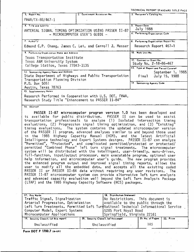
TECHNICAL REPORT ST ANDARD TITLE PAGE
1. Report No. 2. Govt"tnment Acces'lon No. 3. Rec,p,ent's Catalog No.
FHWA/TX-88/467-1 ~4-. ~T~,tl~e-an~d~S~ub-ti~Ile-------------~-------------------------+·5.~Re-p-or-t~Da-Ie--------------------
ARTERIAL SIGNAL TIMING OPTIMIZATION USING PASSER II-87 t-.,--=-Ju---:-l_y_1_9~88 __ ~:---___ ~ - MICROCOMPUTER USER'S GU I DE _ 6. Performing Organ,zalion Code
7. Author'.: B. Performing Organi zatian Report No.
Edmond C.P. Chang, James C. Lei, and Carroll J. Messer Research Report 467-1
9. Perform,ng D'Qanl zatlon Name and Addre ..
Texas Transportation Institute Texas A&M University System College Station, Texas 77843-3135
10. Work Unit No.
II. Contract or Grant No.
Study No. 2-18-86-467 13. Type 01 Report and Pe"ad Covered
----------------------------~ 12. Sponsoring Agency Name ond Address September 1, 1985 State Department of Highways and Public Transportation Final July 15, 1988
I Transportation Planning Division P.O. Box 5051 Austin, Texas 78763 15. Supplementary Notes
14. Sponsoring Agency Code
Research Performed in Cooperation with U.S. DOT, FHWA. Research Study Title "Enhancement to PASSER II-84"
16. Abstract
PASSER 11-87 microcomputer program version 1.0 has been developed and is available for public distribution. PASSER II can be used to assist transportation professionals to analyze (1) Isolated intersection timing evaluations, (2) Progression signal timing optimization, and (3) "Existing" timing evaluations. The system contains the updated microcomputer version of the PASSER II program, advanced analyses similar to and beyond those used in the 1985 Highway Capacity Manual (HCM), and the latest Artificial Intelligence technology and Expert Systems designs. PASSER 11-87 can analyze "Permi tted", "Protected", and comp 1 i cated permi tted/protected or protected/ permitted "Combi ned Phase" 1 eft turn signal treatments. The mi crocomputer system will be distributed with the intelligent, user-friendly, menu-driven, full-function, input/output processor, main executable program, optional user help information, and microcomputer user's guide. The new program provides the enhanced program output and improved signal timing reports, allows the user to modify all the embedded data, and accepts all the existing coded PASSER II or PASSER II-84 data without requi ri ng any user revi s ions. The PASSER 11-87 microcomputer system can provide alternative left turn analysis and advanced capacity evaluation well beyond the Left Turn Analysis Package (LTAP) and the 1985 Highway CapaCity Software (HCS) packages. _
17. Key Warda
Traffic Signal, Signalization Arterial Progression, Optimization Left Turn Treatments, Permitted Left Tur Computer Model, Expert Systems Microcomputer Applications
18. Distribution Stotement
No Restrictions. This document is available to the public through the National Technical Informational Service 5285 Port Royal Road Springfield, Virginia 22161
19. Security Clauil. (of this report) 20. Security Claufl. (of this poge) 21. No. of Pog.. 22. Price
Unc 1 ass ifi ed Unclassified 105
Form DOT F 1700.7 II-UI
E' ,,"

ARTERIAL SIGNAL TIMING OPTIMIZATION USING PASSER 11-87
- MICROCOMPUTER USER'S GUIDE -
By
Edmond Chin-Ping Chang, PhD., PEe Assistant Research Engineer
and
James Chiang-Kuo Lei Research Associate
and
Carroll J. Messer, PhD., PEe Research Engineer
Traffic Operations Program Texas Transportation Institute Texas AiM University System
College Station, Texas 77843-3135
Research Report Number 467-1
Research Study Number 2-18-86-467
Sponsored by
Texas State Department of Highways and Public Transportation
July 1988

S,.~.I
In It yd ml
oz Ib
ISp
Tbop fI DZ
'F
Approximat. Conv.raions to M.tric M •• urlS
Whl. Yell ....
IAChe.
tee' ,onI. mile.
..... inches Iquere , •• , square V., aquAr. rni I •• .u ••
ounce. pounds short ton.
12000 Ib)
te •• poons tabl •• poeM"
tlutd ounc ••
CUP' pln,a q..anl g.IIOftI cubic teet cubic yards
• ... ltifl' ~,
LENGTH
·2.~
30 0.9 1.1
AREA
6.5 0.09
0.' 2.1 0.4
MASS (w.i,ht,
28 0.4~
0.9
VOLUME
6 16 30 0.24 0.47 0.96 3.8 0.03 0.76
TEMPERATURE (SXlct,
fllhrenheit temperature
5/91olt .. subtracting
321
h fi.~
centimeters c_,unele,. ...... n kiiomelet'l
llqUMe c .... tlmet .... aqua,. me .... . aquwe ,... .... . aq...,. kilomet .... hectar ••
gr ..... kilograms tonne.
milliliters millilite,. milllli •• r.
lile ... litefs liters liten cubiC met •• cubIC meters
Celsius temperAtUfe
S,.hl
em em m 11m
9 kg
ml ml ml
'c
METRIC CONVERSION FACTORS
... -
. -
...
... -
., ..
.. .. -_ .. _--
;:
------
...
...
Sy.~.1
mm em m m 11m
g kg
'c
Apprui.ata Conv.rsion fr •• M.tric M .... r ..
Will. v.. K •••
mllllmete,S
cent .meters mete,s meters
kilometa"
LENGTH
0.04 0.4 3.3 1.1 0.6
AREA
_. cont....... 0.11 _.me.... 1.2
squIIfe kll..-.er. 0.' _ •• 110.000 ml) 2.5
MASS (w.itht,
gnms 0.035 kllogr_ 2.2 t..-. (1000 kg) 1.1
VOLUME
milllli.er. 0.03 .i'.... 2.1 liters 1.06 li'efS 0.21 cubiC mel... 36 cubtc me'._ 1.3
TEMPERATURE IlIlCt,
Celsius temper_lure
9/6(_ _32)
r. fi.~
Inches
Inches .... yMds mi) ••
...... inche. -y ..... aqu.. mil., I","
..-.. pounds short toni
fluid ounc •• pints quan. gallons cubtc f •• t cubic y.rds
Fa ... enheit
' ..... '.tUfe
OF
OF 32 9 .. 6 212
-4f~-L-r-L~I~~-L'lrL'-411_4~~-tI-L",~,_8~~,I~,~lTI~'_I~~rO~I-tI-LI~ .. lr~_O~",~,~,T;~~-1do _:g -20 0 20' J40 60 80 oC
S,.~.I
in in It yd mi
Oz
Ib
'F

ABSTRACT
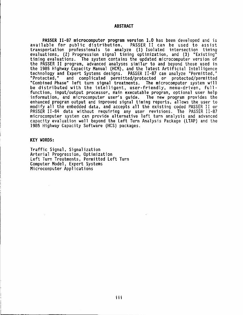
PASSER 11-87 microcomputer program version 1.0 has been developed and is available for public distribution. PASSER II can be used to assist transportation professionals to analyze (1) Isolated intersection timing evaluations, (2) Progression signal timing optimization, and (3) "Existingll timing evaluations. The system contains the updated microcomputer version of the PASSER II program, advanced analyses similar to and beyond those used in the 1985 Highway Capacity Manual (HCM) , and the latest Artificial Intelligence technology and Expert Systems deSigns. PASSER II-87 can analyze "Permitted, II "Protected," and complicated permitted/protected or protected/permitted "Combined Phase" 1 eft turn signal treatments. The mi crocomputer system will be distributed with the intelligent, user-friendly, menu-driven, fullfunction, input/output processor, main executable program, optional user help information, and microcomputer user's guide. The new program provides the enhanced program output and improved signal timing reports, allows the user to modify all the embedded data, and accepts all the existing coded PASSER II or PASSER 11-84 data without requiring any user revisions. The PASSER 11-87 microcomputer system can provide alternative left turn analysis and advanced capacity evaluation well beyond the Left Turn Analysis Package (LTAP) and the 1985 Highway Capacity Software (HCS) packages.
KEY WORDS:
Traffic Signal, Signalization Arterial Progression, Optimization Left Turn Treatments, Permitted Left Turn Computer Model, Expert Systems Microcomputer Applications
iii
SUMMARY
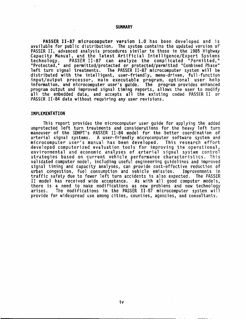
PASSER II -87 mi crocomputer versi on 1. 0 has been developed and is available for public distribution. The system contains the updated version of PASSER II, advanced analysis procedures similar to those in the 1985 Highway Capacity Manual, and the latest Artificial Intelligence/Expert Systems technology. PASSER 11-87 can analyze the complicated "Permitted," "Protected," and permitted/protected or protected/permitted "Combined Phase" 1 eft turn signal treatments. The PASSER II -87 mi crocomputer system will be distributed with the intelligent, user-friendly, menu-driven, full-function input/output processor, main executable program, optional user help information, and microcomputer user's guide. The program provides enhanced program output and improved signal timing reports, allows the user to modify all the embedded data, and accepts all the existing coded PASSER II or PASSER 11-84 data without requiring any user revisions.
IMPLEMENTATION
This report provides the microcomputer user guide for applying the added unprotected 1 eft turn treatments and cons i derat ions for the heavy 1 eft turn maneuver of the SDHPT's PASSER II-84 model for the better coordination of arteri a 1 signal systems. A user- fri endly mi crocomputer software system and microcomputer user's manual has been developed. This research effort developed computerized evaluation tools for improving the operational, environmental and economic analyses of arterial signal system control st ra teg i es based on current veh i cl e performance cha racteri st i cs. Th is validated computer model, including useful engineering guidelines and improved signal timing and capacity analyses, can provide cost-effective reduction of urban congestion, fuel consumption and vehicle emission. Improvements in traffic safety due to fewer left turn accidents is also expected. The PASSER II model has recei ved wi de acceptance. As with a 11 good computer models, there is a need to make modifications as new problems and new technology ari ses. The modifi cat ions in the PASSER II -87 mi crocomputer system wi 11 provide for widespread use among cities, counties, agencies, and consultants.
iv
DISCLAIMER
The PASSER 11-87 microcomputer program was developed under Texas State HP&R 2-18-86-467 study by the Texas Transportation Institute of Texas A&M University System. It was designed for use by traffic engineers and other transportation professionals. This program can be used to optimize or evaluate a single isolated signalized intersection or a coordinated arterial signal system of up to twenty (20) intersections. Care should be taken to make sure the program package, which includes the user's documentation, remains intact. If the package elements become separated, program effectiveness may be impaired severely.
Pl ease be advi sed that no warranty is made by the Texas Department of Highways and Public Transportation, the Federal Highway Administration, the Texas Transportation Institute, or Texas A&M University System as to the accuracy, completeness, reliability, usability, or suitability of the computer program and its associ ated data and documentat ion. No respons i bil ity is assumed by the above part i es for the incorrect results or damages resulting from its use.
PASSER II-87 software and related documentation are copyrighted. This software and documentation may not be copied or reproduced for commercial purposes. Modifications or alterations in the meaning, intent, applications, or operations of the software or documentation is absolutely prohibited unless prior approval has been obtained from Texas Transportation Institute (TTl).
TRADEMARK
PASSER (trademark application pending) is a mark of the Texas Transportation Institute (TTl). As such, any use of this mark must have prior written approval from TTl.
~COPYRIGHT 1988, Texas Transportation Institute, All Rights Reserved.
Use of the.PASSER mark,· software, or documentation in whole or part within the body of another work, except for bri ef citations, is prohi bited. Se 11 i ng or redistributing the PASSER mark, software, or documentation by any person or agency other than TTl and their authorized agents is prohibited.
v
TABLE OF CONTENTS
INTRODUCTION .....
System Features.
Program Implementation
Microcomputer System Highlights.
PASSER 11-87 MICROCOMPUTER ENVIRONMENT SYSTEM
PASSER 11-87 Input Data Requirements
Movement Designation. . Signal Phasing ..... . Phasing Selections .... .
PASSER 11-87 System Hierarchy.
Configuration Files .. . Batch Files ...... . Executable Files ......... . PASSER Input Data and Output Files. User Global System Help Information
GETTING STARTED WITH PASSER 11-87
System Preparation .
Program Installation
Input Data Coding Using the Floppy Disk System. Input Data Coding Using the Hard Disk System.
Starting The Traffic Data Input System
System Overvi ew . . . . . . Start System ....... . Date and Time . . . . . . . Basic Keyboard Instructions
PROGRAM EXECUTION
Main Menu.
Input Menu
New Traffic Data Input. Embedded Data Input Phaser Data Input
Edit Menu ....... .
vi
1
2
3
4
6
6
8 8 8
14
16 16 16 17 17
18
18
19
19 22
23
23 23 23 24
25
25
29
29 36 39
41
Data Input Assistant Functions.
Left Turn Bay . Traffic Volume. Volume Calculation .. Saturation Flow Rate .... Saturation Flow Calculation Minimum Phase Time .... Minimum Phase Calculation
Saving and Loading Data Sets
Running PASSER 11-87
Output Menu. .
Exiting the Input Preprocessor and Output Postprocessor.
ADDITIONAL CONSIDERATIONS . . . .
Left Turn Signal Treatments.
Left Turn Treatment Data Input Method
Phase Pattern Selection.
Effect on the Left Turn Phase Sequence. Summary of Operational Procedure.
Summary of Keyboard Commands .
43
44 44 44 46 46 51 51
53
53
. 54
57
59
59
59
63
67 68
68
Arterials with a Maximum of 20 Intersections 70
Summary of Operating Procedures. . . . . . . 70
Runni ng PASSER II -87 Through the PASSER II -87 System. . . . .. 71 Running PASSER 11-87 Through Cold Start With Data Modification. 72
Operational Efficiency
Use Subdirectory. . ..... Use BAT Files and the PATH Commands. Choose a DOS Shell Program. Routinely Backup and Purge.
CONCLUSIONS AND RECOMMENDATIONS
ACKNOWLEDGEMENTS.
REFERENCES.
APPENDIX A. APPENDIX B.
Example Input of PASSER 11-87 Program. Example Output of PASSER 11-87 Program
vi i
73
73 73 75 75
76
77
. . 78
80 84
LIST OF FIGURES
1. Functional structure of PASSER II-87 .... . 2. NEMA Numbering System ........... . 3. Alternative Phase Sequences in PASSER 11-87 . 4. Normal and Special Phasing Selection Table in
Microcomputer Environment System .... 5. Example of Signal Phasing Selection in PASSER 6. PASSER 11-87 System Hierarchy ...... . 7. PASSER II -87 DISCLAIMER SCREEN. . . . . . 8. PASSER 11-87 System Configuration Routine 9. PASSER 11-87 Microcomputer Menu Structure.
10. PASSER 11-87 MAIN MENU ......... . 11. PASSER 11-87 INPUT MENU ......... . 12. PASSER 11-87 Arterial Data Input Screen. 13. PASSER II -87 MOVEMENT INPUT SCREEN. . . . 14. PASSER 11-87 Signal Phase Sequence Screen . 15. PASSER 11-87 Arterial Link Geometry Screen .. 16. PASSER 11-87 Embedded Data Input Screen 17. PASSER 11-87 Phaser Data Input Screen 18. PASSER 11-87 EDIT MENU ....... . 19. Traffic Volume Input Assistant. .. . 20. Saturation Flow Input Assistant .. . 21. Minimum Phase Time Input Assistant .. 22. PASSER 11-87 OUTPUT MENU ...... . 23. PASSER 11-87 Printout Selection Menu .. . 24. Input Permissible Phasing for the Arterial 25. Permissive Arterial Phasing .... 26. Permissive Phasing for Cross Street 27. Basic Keyboard Instructions ..... 28. Recommended Subdirectory Structure.
LIST OF TABLES
PASSER 11-87
11-87
7 9
10
12 13 15 20 21 26 27 30 31 33 34 35 37 40 42 45 48 52 55 58 61 65 66 69 74
1. APPROXIMATE SATURATION FLOW RATES FOR GENERAL CONDITIONS IN TEXAS. . 47
viii
INTRODUCTION
PASSER 11-87, an acronym for the Erogression Analysis and ~ignal ~stem fvaluation Routine, is a powerful, easy-to-use, and user-friendly signal timing program for IBM PC/XT/AT or Intel compatible 8088/8086/80286/80386 based microcomputers that have PC DOS or MS DOS 2.1 or higher disk operating systems (DOS). The system operation does not require the use of 8087/80287 math co-processors. The program requires a microcomputer with a minimum of 512K RAM (Random Access Memory) and two 360KB double-sided double-density (OS DO) floppy drives, or one 1.2MB or 1.44MB double-sided high-density (OS HD) floppy disk drive, or a microcomputer system with a hard disk. The first diskette contains the input preprocessor and postprocessor, example data, configuration files, and batch files of the PASSER 11-87 analysis system. The other diskette contains the main program and optional help information of the PASSER 11-87 microcomputer system. However, it is highly recommended that the program be install ed and used on hard di sks for fast execution. The PASSER 11-87 microcomputer program system is distributed with the input preprocessor, output postprocessor, executable main program, optional user help information, and microcomputer user's manual.
PASSER 11-87 seeks to maximize arterial two-way progression and mlnlmlze signal delay by pursuing a series of arterial signal timing optimization processes. Signal timings are calculated to minimize the individual intersection delay based on traffic volumes, saturation flows, and minimum phase times for a given cycle length range. PASSER 11-87 can optimize Signal phasings ranging from two-phase operations to multiphase, variable sequence operations. In addition to the basic "Protected" or "Permitted" left turn phasing, PASSER 11-87 can further analyze the complicated permitted/protected or protected/permitted "Combined Phase" 1 eft turn sequences. Maximum progression efficiency is calculated for the arterial system, given travel speeds and link distances. Optimal phase sequence, phase split timing, and coordinated offsets for each intersection are provided in the solution. Also provided, as requested by the users, is the optimal time-space diagram. Up to twenty (20) signalized intersections can be included in one arterial progressive system. Signal phasing is described on a "Permitted" or "Allowed" phase movement basis. Up to four (4) possible arterial phasing sequences are allowed at anyone intersection. Each cross street can have one (1) of these four signal phase sequences.
A range of cycle lengths can be examined for the optimal progression operation in anyone run. PASSER 11-87 will select the cycle length that can provide the maximum progression efficiency. That is, the program will select the cycle that provides the largest percentage of the cycle for arterial progression. Delay-minimization guidelines are provided as program output for selecting a narrow range of cycle lengths which will yield delay efficient solutions. And last, the program automatically fine-tunes the coordinated progression offsets to further minimize delay to the arrival patterns of the arterial traffic flow. This system offset fine-tuning algorithm in PASSER 11-87 will typically result in a further reduction of 5-15% in delay to the arterial's progressive movements. This system delay reduction is accomplished through the offset fine-tuning algorithm without any loss of arterial progression.
1
As previ ously descri bed, PASSER II -87 is primaril y des i gned to develop timing plans that provide optimal arterial two-way progression. In addition, two other program features shoul d be noted at th is time. The program can develop the time-space diagrams that provide one-way progression in either direction along the arterial street. Also, PASSER II-87 may be used as a traffic planning or capacity analysis tool if volumes, saturation flows, intersection geometrics, and existing signal timings are known. This is because up to a maximum of 20 "isolated" intersections inst.ead of 20 coordinated intersections can be "timed" and "eval uated" simultaneously if desired. The system employs the most advanced highway capacity technology in the model formulation. Besides arterial progression, PASSER 11-87 can also be used to examine isolated intersections by quantifying the geometric, signal control, and traffic flow quality effects. A "Highway Capacity Manual" ana 1 ys is can be conducted in PASSER II -87 . However, the 1985 HCM uses an approximation technique, and PASSER 11-87 uses a more refined model for explicitly describing the left turn traffic maneuver.
SYSTEM FEATURES
PASSER II-87 is designed so that a traffic engineer who is not very familiar with a microcomputer can still effectively begin to use the system to solve his/her arterial signal timing and evaluation problems. The Texas Transportation Institute (TTl) and the Texas State Department of Highways and Public Transportation (SDHPT) have jointly developed the input/output processor (PASSETUP) which permits users to readily establish a traffic data input file. Therefore, it is not required to use the system editor, such as WordStar, WordPerfect, PE or other text editors, to create and modify the PASSER 11-87 data sets in the data input process.
PASSETUP, the mi crocomputer input/output processor, hel ps users input their data through an interactive CRT screen format. Data input guidel ines and a series of help menus are provided to assist users with data input. Rout i ne checki ng for data codi ng errors is provided. A data modifi cat ion facility also allows users to modify the data and provides a reference list of input guidel ines for convenient reference without having to exit the PASSER 11-87 system. After all data input is complete, PASSETUP collects the data, rearranges it into a standard 80-column card-image ASCII text data format, and then automatically stores it in a data file selected by the user for ready access or later modification.
PASSER 11-87 provides an exceptional list of output features. The output is headed by an echo listing of the system embedded data, the coded input data structured around arterial system parameters, and the intersection variables. The output of the optimized solution provides a listing of the optimal timings for the arterial street, optimal signal timing plans for each intersection, a series of level of service evaluations for each phase, the signal controller phase interval setting report, an optimal time-space diagram, and the optional packed data array debug printouts. The implementation of the optimal signal timings is greatly aided by the provision of a complete set of phase interval tables with respect to the system master intersection. This is a new system programming feature for applications on the microprocessor-based traffic actuated signal equipment.
2
PROGRAM IMPLEMENTATION
PASSER II-87 is a computer program that can be used for arterial progression signal timing optimization and intersection capacity analysis. It has a complete stand -alone user interface for mi crocomputer app 1 i cat ions. PASSER 11-87 is an engineering tool used to calculate the green timings, phase sequence, and coordinated offsets for multiphase arterial signal systems. The generated solutions produce minimal delay and provide good arterial progression for a given set of geometric and traffic conditions.
The program permi ts the eng i neer to interact wi th the overall sol ut ion process while relieving the engineer from the tedious and repetitive ca 1 cul at ions. Severa 1 program runs may be needed before the fi na 1 sol ut ion set can be produced. Eng i neeri ng judgment is frequently requ ired in the selection of traffic input parameters. Saturation flow for the basic protected movement is an important program input. The use of a local traffic study or the program's new capacity features is recommended. Some estimation regarding saturation flow rate is provided in the input coding instructions and may also be used where no other guidance is available. Interactions of left turn bay geometrics, existing volume loadings, and apparent volume-tocapacity ratios must be subjectively and judgmentally evaluated to estimate their individual and collective effects on intersection capacity and resulting saturation flow.
Cycle length selection is the single most important decision that must be made by users of PASSER 11-87 during arterial signal timing optimization. All intersect ions in the progress i ve system must operate on the same background cycle length. Due to the nature of the analysis capability of the PASSER 11-87 system, no double cycl ing is permitted. Judgmental tradeoffs may be made between quality of arterial progression and total arterial delay. PASSER 11-87 can automatically examine a range of cycle lengths and will select the cycle length providing the best progression. However, total arterial delay is highly dependent on the selection of cycle length. Consequently, the cycle range to be examined should be carefully selected if minimizing delay is an important objective. It is recommended that addit i ona 1 runs be made and examined using one reasonable cycle length, such as the "MAXIMUM CYCLE LENGTH" described below, which should be initially selected for the given data set.
One useful output of this initial program run would be a list of "minimum de 1 ay" cycle 1 engths for each intersect i on as if each were an i so 1 ated intersection. It is recommended that the "MAXIMIN CYCLE LENGTH," i.e., the maximum of the minimum delay cycle lengths, be included within the cycle length range examined. However, the range of cycle lengths should not exceed 10 seconds. The lower limit of the cycle length range should not be less than 90% of the maximin cycle. For example, assume that the maximin cycle is 94 seconds. 90% of 94 is 84.6 seconds. The recommended cycle range would be from 85-95 seconds. PASSER 11-87 should be run using this particular range of cycle lengths to determine optimal arterial progression with the user knowing that the total arterial system delay will be near the minimum value.
Excessively long minimum delay cycle lengths are suggestive of a capacity problem. Methods should be sought to increase the capacity of the critical intersection(s). For example, a series of traffic engineering improvements can be made to the facilities, such as added lanes, restriped pavement, restricted parking, etc., to improve the capacity of the intersections.
3
- --------------
In addition, excessively long cycle lengths tend to overflow left turn bays or back queues into the upstream intersections or driveways. These actions could further reduce signal capacity. The phase sequence selection process involves another series of traffic engineering judgments. In addition to considering the effects on coordinated arterial signal progression, several other factors should also be considered. These factors include the type of traffic signal control equipment, turning movement volumes, left turn bay storage capacity, and pedestrian signal timing requirements.
It is suggested that the first program runs be made separately for the AM peak, PM peak and Off-peak traffic conditions which will allow all the possible signal phase sequences to determine which phase sequences provide the best overall progression. The user may also wish to run a "preferred" set of phasing sequences for each time period in order to evaluate the relative loss in arterial progression that might occur when using only the preferred phase sequence choice at each intersection. If the arterial traffic control system permits only one phase sequence per intersection, then a final phase sequence must be selected for each intersection for all the AM, PM and Off-peak conditions. If the same phase sequence was selected for all three initial AM, PM and Off-peak runs, then it probably should be used in the final program runs. Finally, AM, PM and Off-peak program runs should be made after a thorough study of a 11 the previ ous runs has been made. Loca 1 experi ence and traffic control capabilities can determine whether the phase sequence used in the final timing plans is the same or different for each intersection.
PASSER 11-87 calculates phase green time requirements from volume data to develop optimum progression solutions. The program may, however, be used to develop an improved progression solution when the green times and cycle length are already known. The given cycle length is entered as is. The phase times for the movements, i. e., the green plus yellow and a 11-red, are entered as minimum phases. The user may enter actual volumes and saturation flows or dummy values. For example, the user may enter 1 for volume and 10 for saturation flow for each phase. The program will use the minimum phases as the actual greens. Phase selection by the program is made as appropriate.
Isolated timing and evaluation can also be performed through the PASSER 11-87 system. The traffic data coding system expedites the data entry process. All the arterial progression aspects are automatically deleted from the input data coding procedure. PASSER 11-87 is a program written by traffic engineers for traffic engineers. It only calculates; it does not engineer. It mayor may not detect your errors or ana lys is intentions. As one gains experience with the program, personal skill will improve, and the number of alternative solutions that can be considered will greatly increase.
MICROCOMPUTER SYSTEM HIGHLIGHTS
The PASSER 11-87 Microcomputer Environment System was developed by the Texas Transportation Institute (TTl) for the Texas Department of Highways and Public Transportation (SDHPT) to facilitate use of the microcomputer version of PASSER 11-87. The analysis system is designed for use on an IBM PC/XT/AT or compatible microcomputer. The new system has the following advantages over the existing PASSER 11-84 Microcomputer Program Version 3.0:
4
(1) Provides user-friendly, menu interface, and full-cursor movements.
(2) Accepts all existing PASSER 11-84 data without user modification.
(3) Allows user modification of all embedded data for analysis.
(4) Uses the graphical traffic movement input and provides the "ASSISTANT" function for helping users to prepare data for 1985 HeM type signalized intersection capacity analysis.
(5) Is capable of analyzing all the commonly available left turn signal treatments. These features include:
a. With or without a protected left turn bay. b. With or without a protected left turn phase. c. Combined phase analysis. This analysis includes the optional
"Protected plus Permitted" or the "Permitted plus Protected" left turn signal phasing schemes.
(6) Provides an input scheme for developing an evaluation of existing or user-selected arterial signal offsets.
(7) Reports all the embedded data used in the analysis.
(8) Provides an improved user-specified controller Phase Interval Setting (PIN) report, progression bandwidth coordinates, and an enhanced Time-Space diagram.
This "Microcomputer User's Guide" was written for those users who are already familiar with the PASSER II program and desire to use the PASSER 11-87 microcomputer program to analyze arterial signal system design problems. Any questions concerning how the PASSER II program operates or what type of data input it needs is specifically addressed in the "PASSER II User's Manual." Hopefully, the user will find the data input system to be easy to work with, but if one should have any unresolved questions, call the Texas Transportation Institute at (409) 845-9873 or TexAn 857-9873, or call the Texas SDHPT at (512) 465-8353 or TEXAn 258-8353. It will be appreciated if calls are placed only when this manual does not provide the needed information. Please consider that software support is in addition to the regular duties of the Texas Transportation Institute and the Texas SDHPT.
Please address all written correspondence to:
Texas Department of Highways and Public Transportation File D-18STO 11th and Brazos Streets Austin, Texas 78701
And questions concerning loading and obtaining of the disks to:
Texas Transportation or Technology Transfer
Texas A&M University College Station, Texas 77843 Phone: 1-800-824-7303
5
McTrans Center University of Florida 512 Well Hall Gainesville, Florida 32611 Phone: 904-392-0378

PASSER 11-87 MICROCOMPUTER ENVIRONMENT SYSTEM
The basic theory of the PASSER II was originally developed at the Texas Transportat ion Institute (TTl), Texas A&M Uni versity System for the Da 11 as Corridor Project sponsored by the Federal Highway Administration (FHWA), U.S. Department of Transportation. The PASSER II program was originally developed for applications on the mainframe computer systems of the Texas State Department of Highways and Public Transportation (SDHPT). PASSER 11-87 is the most recent and enhanced version of the PASSER II program.
PASSER 11-87 is a computer program that can analyze both the individual signalized intersections and arterial progression optimization. It was originally designed for high-type arterial streets with the separate protected left turn lanes and protected left turn phases. Also, it provides optimized timing plans for modern eight-phase controllers. The theory, model structure, methodo logy, and 1 ogi c of PASSER II -87 have been evaluated and documented. PASSER II has received widespread usage because of its abil ity to rapidly select multiple phase sequences for maximized arterial progression. PASSER 11-87 maximizes total two-way progression bandwidth efficiency. In the optimization process, it varies the Signal phasing and offset at each intersect i on wi th cycle and progress i on speed changes to fi nd the opt i ma 1 timing plan which both maximizes the arterial progression bands and minimizes the total arterial system delay.
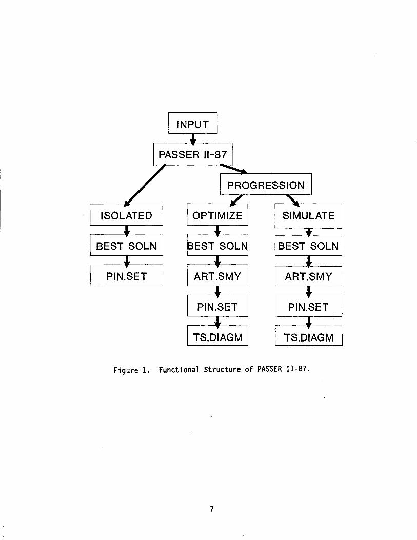
The PASSER 11-87 system is an engineering tool which combines the updated version of PASSER II-87, advanced analysis procedures similar to and beyond those in the 1985 Highway Capacity Manual (HCM), and the latest developments in mi crocomputer programmi ng technology. The funct i ona 1 structure of PASSER II-87 is illustrated in Figure 1. It can be used to assist transportation professionals to analyze (1) Isolated intersection timing evaluations, (2) Progression signal timing optimization, and (3) IIExisting Timing Evaluations ll or IISimulation Evaluation. 1I Much of the input data is similar to those input data required for other signal timing optimization programs. To analyze an isolated signalized intersection, traffic turning movements and intersection approach saturation flow rates are needed. Minimum phase times for each movement must also be provided. At present, the program assumes the isolated intersection evaluation if the input data pertain to only one intersection. On the other hand, this program assumes progression if the input data spec i fi ed include more than one signal i zed intersect ion in the arterial system.
PASSER 11-87 INPUT DATA REQUIREMENTS
Most input data required for the PASSER 11-87 microcomputer system are the same as those used in the mainframe version of PASSER 11-87. The user may input data from the mi crocomputer input processor or download the data files straight from the mainframe computer to execute the program. Since there are no input/output processors provided by the mainframe computer, it is then possible to create or modify the input data files on the microcomputer and upload the files to the mainframe for faster execution. The most important input data requirements are the National flectrical Manufacturers' Association (NEMA) phase movement designation, selection of signalization designation, and the phasing sequence inputs.
6
INPUT ,L. '"
PASSER 11-87 ....
/ -.......... PROGRESSION ./ "-~ ~ -
ISOLATED OPTIMIZE SIMULATE ~ J, .. .. ..
BEST SOLN BEST SOLN BEST SOLN ,L. ,L. , '" ..
PIN.SET ART.SMY ART.SMY ,L. J, .. ..
PIN.SET PIN.SET ,L. ,L. '" ..
TS.DIAGM TS.DIAGM
Figure 1. Functional Structure of PASSER 11-87.
7
Movement Designation
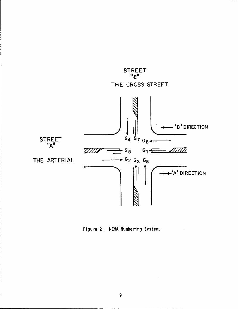
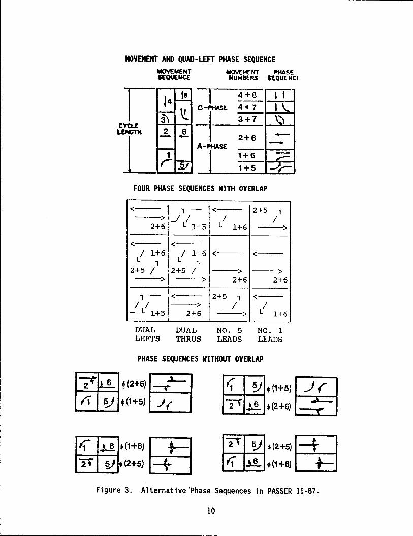
Intersection specific movement data are input according to the NEMA movement designations shown in Figure 2. In this figure, separated left turning movements are represented by the odd numbers, Movements 1, 3, 5, and 7. The "l eft turn protect i on II may be prov i ded either by a separate 1 eft turn 1 ane, 1 eft turn bay, or by a protected 1 eft turn signal phase. On the other hand, left turning volumes not protected by an exclusive left turn lane and left turn phase will be combined with traffic volumes in the adjacent through lanes. As illustrated in Figure 3, the main and cross street phases are generated by the combinations of the eight numbered movements, starting at the beginning of each signal phase. Movements 1, 2, 5 and 6 are used exclusively for the main street. Likewise, movements 3, 4, 7 and 8 are used only for the cross street. In this NEMA movement numbering scheme, PASSER II calculates the progression operation beginning at the start of the first phase for the arterial street. At those signalized intersections that have no protected left turn phases, left turn movements 1, 3, 5, and 7 are merged into the adjacent through movements. Traffic volumes for each through phase movement are normally the total traffic vo 1 umes for the through plus ri ght turns. A 1 so, it may be des i rab 1 e to provide some reduction in right turning volumes for considering the separate effects of right turning lanes or free right turn traffic movements.
It is highly recommended that all saturation flow adjustments for unprotected turns be made to the corresponding left turn phase movements using the "ASSISTANT" function. It is also recommended that no adjustment be made to the traffic volume for a more accurate estimate of the vehicular delay. PASSER 11-87 outputs the traffic volumes, saturation capacity flow, and minimum phase times that are required to satisfy the necessary pedestrian crossing and minimum protected green phase with respect to the NEMA movement phase designation.
Signal Phasing
PASSER 11-87 models a common, high-type, coordinated multiphase Signal phasing in a "quad-left" traffic signal control system. PASSER 11-87 input uses the minimum information to generate the possible left turn treatments as we 11 as all owab 1 e signal phase sequences. The input data was des i gned to simplify the user's input for analyzing the various possible left turn signal treatments and capacity evaluations. These range from the most simple twophase "Permitted Phase" and sophisticated "Protected Phase" operations, to the most complicated permitted/protected or protected/permitted "Combined Phase" 1 eft turn sequences. PASSER 11-87 provides for di fferent phase sequences to be displayed on each arterial street. In the analysis, there must be at least one (1) to the maximum of four (4) allowable phase sequences selected for the main street and only one (1) of the four possible phase sequences specified for the cross street. Phase sequences without overlap are also called "split phase.
Phasing Selections
The sequence of the numbered movements defines the phasing sequence for either the main or cross street phase movements. Four allowable phasing sequences are used in PASSER 11-87. As shown in Figure 3, these alternative arterial phasing sequences include four possible signal phasing selections.
8
STREET "A"
THE ARTERIAL
STREET .. e"
TH E CROSS STREET
II! · '8' DIRECTION
G4 G7 G6 4.---
~\\\\\?" --.! G 5 G1 ..---- A\\~
--... G2 G3 Ge
11 1 ~ 'A' DIRECTION
Figure 2. NEMA Numbering System.
9
MOVEMENT AND QUAD-LEFT PHASE SEQUENCE MQVEMEKT ~E NUMBERS SEOUENCI
la 1 4 + 8 I t
~~~ _c_-.J-PtiASEI __ :_:_~_I-_I.~~ I....~ 2+6
AaPHAS£ -1+6 -1+5
FOUR PHASE SEQUENCES WITH OVERLAP
< 1 - < 2+5 1 > ...JI LI I
2+6 L 1+5 1+6 >
< < LI 1+6 LI 1+6 < <
1 1 2+5 I 2+5 I > >
> > 2+6 2+6
1 - < 2+5 1 < I I > I LI - L 1+5 2+6 > 1+6
DUAL DUAL NO. 5 NO. 1 LEFTS THRUS LEADS LEADS
PHASE SEQUENCES WITHOUT OVERLAP
7~ f(2+6) -..~ (1 f?J ~ (1 +5) .) (
i1 II ~(1+6) I :: I 2t ~ ~ (2+5) -+ l21t~t(2+~ [±J
11 .1!-. (1 +6) CB Figure 3. Alternative "Phase Sequences in PASSER 11-87.
10
o Left-Turns First or Dual Lefts Leading or Dual Lefts Lead
o Through Movements or Dual Throughs Leading or Dual Thrus Lead
o Leading Green
o Lagging Green
or Leading Left Leading or NEMA No. 5 Lead
or Lagging Left Leading or NEMA No. 1 Lead
Figure 3 illustrates a typical "overlap" signal phasing sequence in PASSER II-87. Concurrent timing of the non-conflicting pairs of phases, s imil ar to the ri ng 1 and ri ng 2 concept in actuated control, are always assumed with overl apped ph as i ng. Consequently, three compound phases can be displayed within the street's phase sequence. When no overlap exists in the phase sequence, only two compound phases may arise, as shown in Figure 3. PASSER II -87 can maximi ze arteri a 1 progress i on by opt imi zi ng the phase sequence, cycle length, progression speeds, and coordinated offsets. A total of eight phasing sequences are possible for both the arterial and cross street directions in the PASSER II-87 system. Since no explicit investigation is carried out to optimize the cross street phase sequence, the user must input one and only one phase option for the cross street movements in PASSER 11-87.
The following study procedure is implemented in the PASSER 11-87 input preprocessor to identify the logical input selection for determining the proper signal phasing arrangements.
Step 1. Identify the existing movements;
Step 2. Identify the possible phasings;
Step 3. Describe the phase order for each phase;
Step 4. Describe the phase overlap for each phase; and
Step 5. Determine the phase code for each phase.
A. Normal Phase Selection - System generated phase.
B. Special Phase Selection - User selected phase.
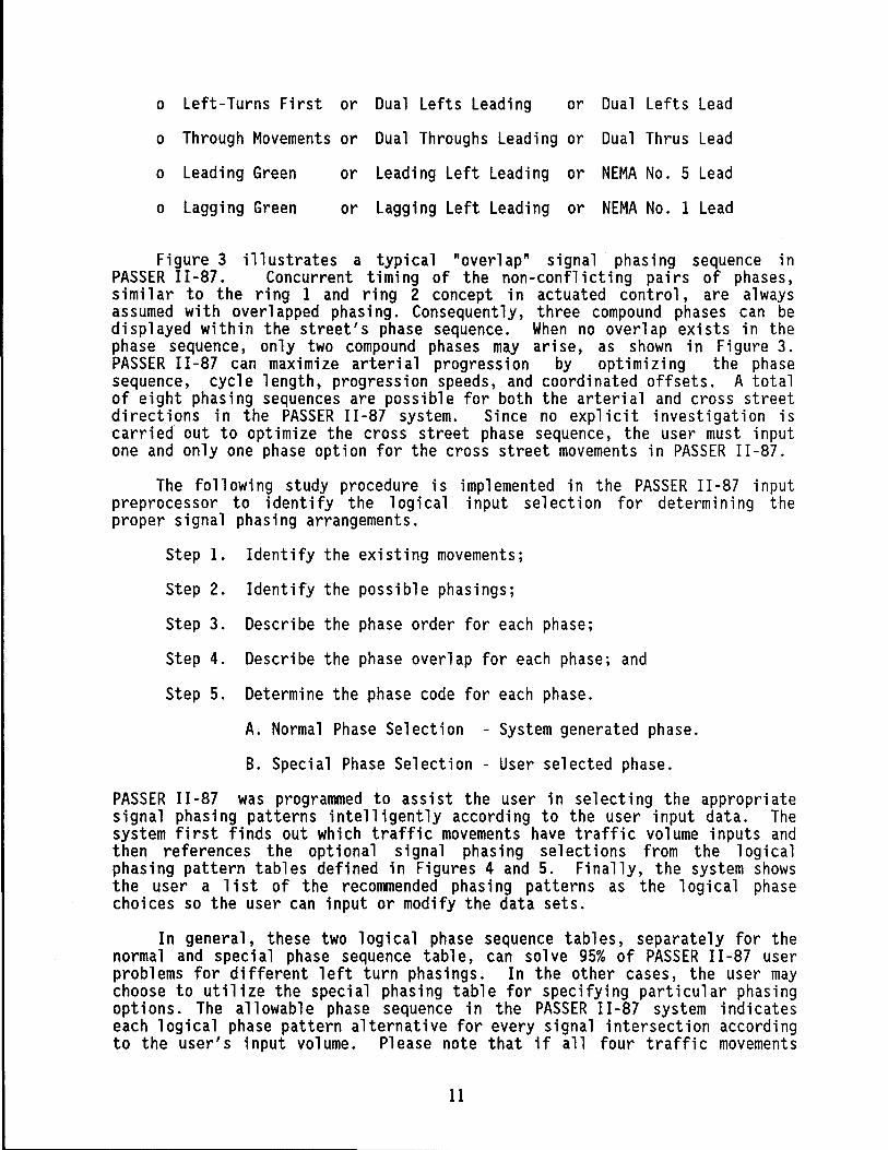
PASSER 11-87 was programmed to assist the user in selecting the appropriate signal phasing patterns intelligently according to the user input data. The system first finds out which traffic movements have traffic volume inputs and then references the optional signal phasing selections from the logical phasing pattern tables defined in Figures 4 and 5. Finally, the system shows the user a list of the recommended phasing patterns as the logical phase choices so the user can input or modify the data sets.
In general, these two logical phase sequence tables, separately for the normal and special phase sequence table, can solve 95% of PASSER II-87 user problems for different left turn phasings. In the other cases, the user may choose to utilize the special phasing table for specifying particular phasing options. The allowable phase sequence in the PASSER II-87 system indicates each logical phase pattern alternative for every signal intersection according to the user's input volume. Please note that if all four traffic movements
11
1
X
X X
X
X X X
X
3
X
X X
X
X X X
X
NORMAL PHASING
Movements 2 5
X X
X X
X X
X X
X X X
X X X X X
Movements 4 7
X X
X X
X X
X X
X X X
X X X X X
Arterial
Phasing Patterns 6 LT
---X ----X -X -X -
2 X -X 2 X -X 3
Cross Street
THH
-1 -1 ----1 --2 -2 3
U '} '5
1
2 2
1
2
2 3 3
Arterial
1 3
X
X X
X
SPECIAL PHASING
or Cross Street Special Phasing Patterns
Movements Phasing Patterns 2 5 6 LT THRU II '5 4 7 8 LT THRU '3 '7
- - 1 -X - 1 - -
X - - - 1 X - 1 - -
X - 1 1 -X 1 - 1 1
X X 1 1 - 1 X 1 1 } -
X X - 1 1 1 Phasing Patterns
RU n '7 X X
X -3
1 - 1 1 } 3 8 LT
---X --
1 -
X -X -X -
2 X -X 2 X -X 3
LEGEND:
Figure 4.
TH
-1 -}
1 ---1 2 -2 -2 3
X -1 2 3
X X X X X 1 X X X 3
X X X 1 X X X X 3
1 1 1 1
2 2
2 2
2 3 3
Movement has volume greater then zero Pattern not allowed Pattern allowed without overlap Pattern allowed with overlap Pattern allowed with or without overlap
3 }
3 3
N P ormal and Special Phasing Selection Table in ASSER 11-87 Microcomputer Environment System.
12
3 }
3 1 1 3 3 3
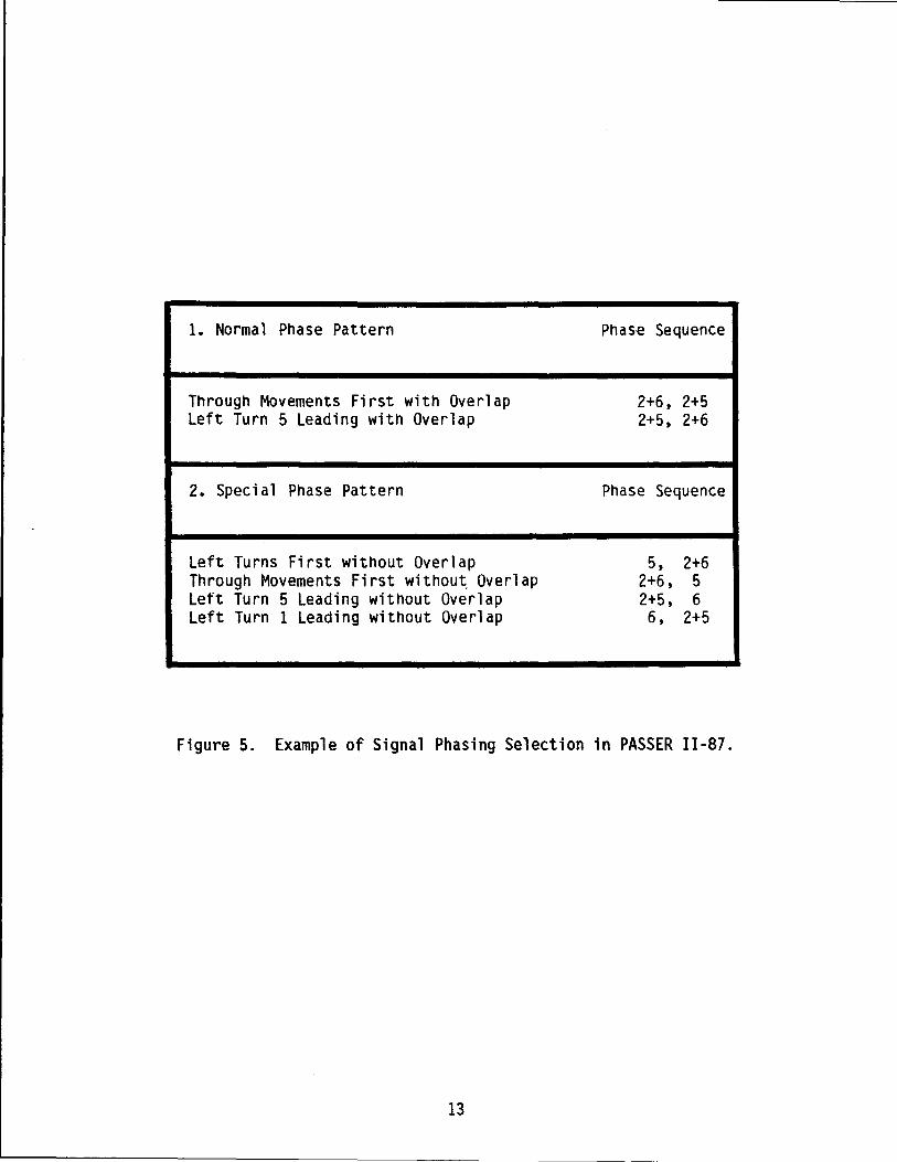
1. Normal Phase Pattern
Through Movements First with Overlap left Turn 5 leading with Overlap
2. Special Phase Pattern
left Turns First without Overlap Through Movements First withou~ Overlap left Turn 5 leading without Overlap left Turn 1 leading without Overlap
Phase Sequence
2+6, 2+5 2+5, 2+6
Phase Sequence
5, 2+6 2+6, 5 2+5, 6 6, 2+5
Figure 5. Example of Signal Phasing Selection in PASSER 11-87.
13
have nonzero volumes, only one of the two possible overlap phases will be shown for the patterns with overlap. The other overlap phase is available and will be chosen by PASSER II-87 only if the overlapped signal phase can be warranted by the corresponding traffic volume.
Figure 4 illustrates the possible phase selection from the logical phas i ng sel ect i on procedure defi ned in the PASSER II -87 mi crocomputer environment system. The vertical rows indicate the four major logical phase sequences allowed for both the arterial and cross street directions as indicated earlier. The horizontal columns illustrate the combination of fifteen (15) movement possibilities according to the existence of one, two, three, or four traffic movements at the particular intersection. As described earlier, a total of four (4) possible phase sequences are allowed for the arterial street travel directions. At the same time, only one (1) signal phase sequence is allowed for the cross street traffic movements.
In the example signalized intersection, suppose that the arterial left turn movement 5 has a protected left turn phase, but the opposing left turn movement or NEMA number 1 does not have a separately protected 1 eft turn phase. The three arterial traffic movements 2, 5 and 6 have nonzero volumes. In the normal phasing pattern table for selecting arterial Signal phasing, there are only two possible logical phase pattern choices that can be specified in the PASSER 11-87 microcomputer environment system. These sequences are the "Through Movement First" and "NEMA No. 5 Lead" in the normal traffic Signal phasing selection process.
In the protected left turn operation, the first logical choice is to use the "Through Movements First With Overlap." This option will give the user a phase sequence of combi ned movement 2+6 and then movement 2+5. The other choice will be the "NEMA Left Turn 5 Leading With Overlap." Specifying this option will give the user the selection of the opposite phase sequence, that is, movement 2+5 and then movement 2+6. In cases in which the user needs a more unusual phase sequence which has not been defined in this logical phasing selection table, the user can go to the special phase pattern table and obtain four more phase selection choices. As indicated in this particular example, there may be a total of six (6) alternative phasing options under the existing traffic volume combination that may be specified in PASSER II-87. These logical choices are the "Normal Phase Pattern" and "Special Phase Pattern" as indicated in Figure 5.
PASSER 11-87 SYSTEM HIERARCHY
The PASSER 11-87 system hierarchy, as illustrated in Figure 6, contains all the component files in the PASSER 11-87 microcomputer environment system. Due to the storage limits on a single 360 KB DO OS floppy disk, PASSER 11-87 is currently restricted to analyzing no more than twenty (20) signalized intersections in one arterial street system. However, systems with more than 20 signalized intersections can be analyzed by separating the arterial Signal system into smaller systems in the analysis.
There are a total of five (5) types of microcomputer system files used in the PASSER 11-87 system for the interactive analysis during the user-machine interface operation. The system includes the configuration files, batch files, executable files, and the basic input data and output files.
14
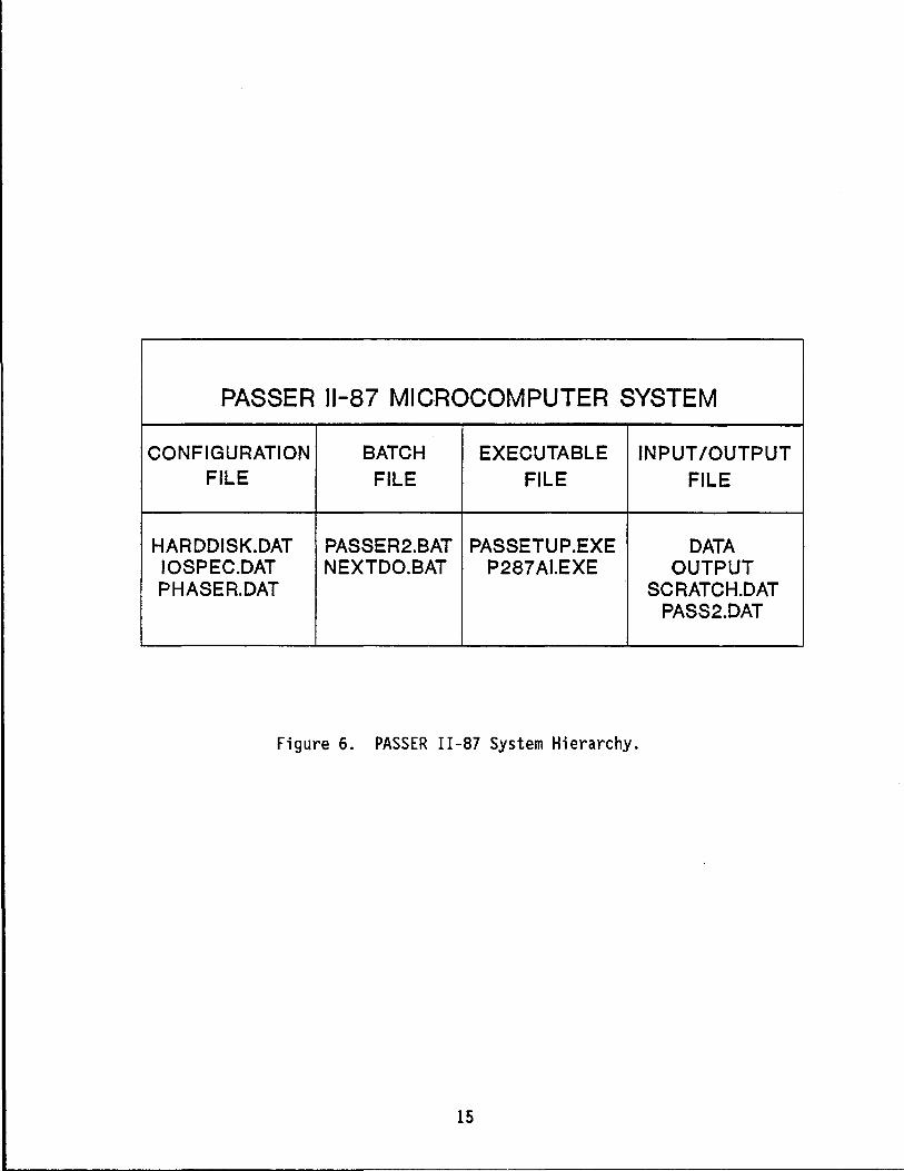
PASSER 11-87 MICROCOMPUTER SYSTEM
CONFIGURATION BATCH EXECUTABLE INPUT IOUTPUT FILE FILE FILE FILE
HARDDISK.OAT PASSER2.BAT PASSETUP.EXE DATA IOSPEC.DAT NEXTDO.BAT P287AI.EXE OUTPUT PHASER.DAT SCRATCH.OAT
PASS2.DAT
Figure 6. PASSER 11-87 System Hierarchy.
15
----- ------------------------------------------
Configuration Files
Three configuration files are provided in the PASSER II-87 system. These include the HARDDISK.DAT, IOSPEC.DAT and the PHASER.DAT files. The "HARDDISK.DAT" file stores the default input file path name for program file storage. These fil es are generated when the system is confi gured us i ng the program package for defining the default program storage, file storage, and input data for both hard disk and floppy disk systems.
HARDDISK.DAT - configures the default path for storing program files. This is a general i zed system confi gurat ion fil e for the program and defaul t data storage. It wi 11 be used duri ng both the floppy drive and hard disk operations.
IOSPEC.DAT - defines the path name and file name for storing user defined input data and output pri ntout fil es. Every time the user saves the data fil e under the specifi ed path name and fil e name, the program will update these file storage destinations along with the user's analysis.
PHASER.DAT - speci fi es the data format and different reference options of PASSER 11-87 Phase Interval Setting (PIN.SET) reports. The detailed elements of the input data for this particular analysis will be discussed in a later section.
Batch Files
The PASSER 11-87 microcomputer system uses two batch files to control the total system operation. The batch files assist the operating system by controlling PASSER 11-87 operation in a user-friendly manner. The batch files are used as an integral part of the PASSER 11-87 program system and must be present during installation and program analysis.
PASSER2. BAT - runs PASSER II -87 envi ronment program from input menu. The user will not have to control the program analysis to shift between the data input, program execut i on, and output operation.
NEXTDO.BAT - controls PASSER 11-87 program input and output operations.
Executable Files
The "PASSETUP. EXE" fil e is programed in the TURBO PASCAL vers ion 4.0 executable binary file format. Compiled PASSER 11-87 (P287AI.EXE) is contained in a linked Microsoft FORTRAN 77 object code. These two executable files must be present for successful PASSER 11-87 program execution.
PASSETUP.EXE - contains input/output menus and data editing routines. This input and output processor is programmed in the TURBO PASCAL structured programming format.
P287AI.EXE - This executable code is the actual compiled FORTRAN 77 version of PASSER 11-87 with all the necessary FORTRAN library calls.
16
PASSER Input Data and Output Files
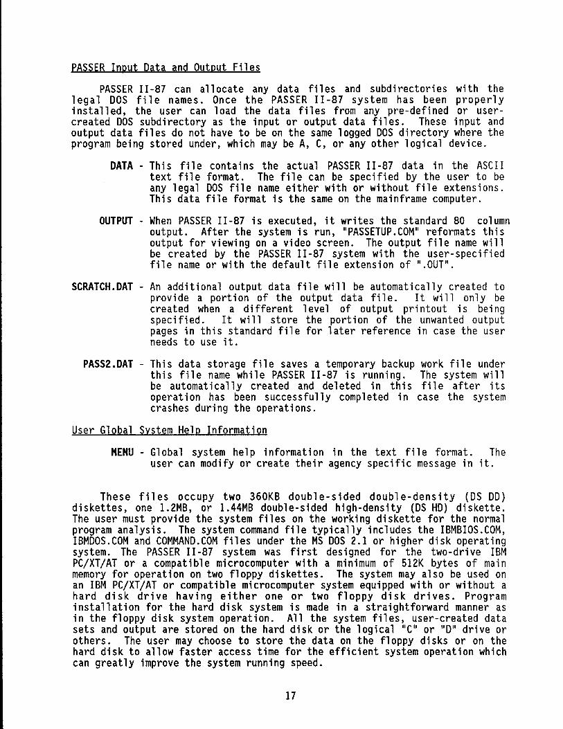
PASSER II -87 can allocate any data fil es and subdi rectori es with the 1 ega 1 DOS fil e names. Once the PASSER II -87 system has been properl y i nsta 11 ed, the user can load the data fi 1 es from any pre-defi ned or usercreated DOS subdirectory as the input or output data files. These input and output data files do not have to be on the same logged DOS directory where the program being stored under, which may be A, C, or any other logical device.
DATA - Th is fil e conta ins the actual PASSER II -87 data in the ASC II text file format. The file can be specified by the user to be any legal DOS file name either with or without file extensions. This data file format is the same on the mainframe computer.
OUTPUT - When PASSER 11-87 is executed, it writes the standard 80 column output. After the system is run, II PASSETUP . COM" reformats th is output for viewing on a video screen. The output file name will be created by the PASSER II -87 system with the user-specifi ed file name or with the default file extension of II.OUTII.
SCRATCH.DAT - An additional output data file will be automatically created to provi de aport i on of the output data fil e. It wi 11 only be created when a different level of output printout is being specified. It will store the portion of the unwanted output pages in this standard file for later reference in case the user needs to use it.
PASS2.DAT - This data storage file saves a temporary backup work file under thi s fil e name whil e PASSER II -87 is runni ng. The system wi 11 be automatically created and deleted in this file after its operation has been successfully completed in case the system crashes during the operations.
User Global System Help Information
MENU - Global system help information in the text file format. The user can modify or create their agency specific message in it.
These files occupy two 360KB double-sided double-density (OS DO) diskettes, one 1.2MB, or 1.44MB double-sided high-density (OS HD) diskette. The user must provide the system files on the working diskette for the normal program analysis. The system command file typically includes the IBMBIOS.COM, IBMDOS.COM and COMMAND.COM files under the MS DOS 2.1 or higher disk operating system. The PASSER II -87 system was fi rst designed for the two-dri ve IBM PC/XT/AT or a compatible microcomputer with a minimum of SI2K bytes of main memory for operation on two floppy diskettes. The system may also be used on an IBM PC/XT/AT or compatible microcomputer system equipped with or without a hard disk drive having either one or two floppy disk drives. Program installation for the hard disk system is made in a straightforward manner as in the floppy disk system operation. All the system files, user-created data sets and output are stored on the hard disk or the logical IIC II or 110 11 drive or others. The user may choose to store the data on the floppy disks or on the hard disk to allow faster access time for the efficient system operation which can greatly improve the system running speed.
17
GETTING STARTED WITH PASSER 11-87
To both first-time users and experienced users, the PASSER II-S7 system, including the input preprocessor, main program, output postprocessor, and the program output listing, will appear familiar, intelligent, and extremely userfriendly. However, first-time users and experienced users of the PASSER II-S4 may be faced wi th different types of operat i ona 1 probl ems when us i ng the PASSER II-S7 system.
Most first-time users of the PASSER II-S7 system will be faced with two general operational questions:
1. How do I load up the program on the microcomputers?
2. How do I get the program to perform the needed tasks?
These operational questions can be resolved by following the procedures stated in this manual which accompanies the PASSER II-S7 diskettes. Experienced users of PASSER II-S4 microcomputer systems may have questions concerning the new terminology used in the new input/output systems. The PASSER II-S7 microcomputer system has been designed to accept all the current input data fil es produced by PASSER II -S4 and provi de the necessary default input data adjustments when the user saves the data in the PASSER II-S7 system. Users may modify these default data as desired or use these recommended values as starting points. A very basic user's training guide is provided in the following sections to assist both the inexperienced as well as the experienced user in "getting this program to run." Detailed operating instructions are given which supplement those provided by the input preprocessor and output postprocessor. All users should be familiar with these instructions and guidelines before beginning serious program execution.
SYSTEM PREPARATION
The PASSER II-S7 program diskettes contain the entire PASSER II-S7 microcomputer system. Since the original distribution program is not configured for booting on MS DOS or PC DOS based microcomputers, it is recommended that the system be copied to a bootable disk, with operating system files, to serve as the working disk. The distributed diskettes can then be kept as the backup diskettes. The program disk is pre-configured for the IBM PC/XT/AT or compatible microcomputer system with two floppy disk drives. If you have a microcomputer system with a hard disk, please read a later section for instructions on setting up and using the system.
It is recommended for users to become famil i ar wi th thei r DOS manual before continuing. the following instructions will be brief, thus, if more explanation is needed, please refer to your DOS manual. First, format a bootable diskette and insert it in drive B. Now, insert the PASSER II-S7 distribution diskette number 1 into drive A and transfer the PASSER II-S7 system by typing in "COPY A:*.* B: /v". All the files will be copied to the B drive. However, the user must make sure that the COMMAND.COM file is on the newly formatted working diskette.
IS
,------------ --- -- ------
The next step is to remove the two diskettes and label the new diskette PASSER 11-87, Version 1. Then insert the number 2 PASSER 11-87 distribution diskette in drive A and a newly formatted diskette in drive B. Repeat the "COpy A:*.* B: /v and the required files will be copied to the B drive.
Remove the diskettes and label the new diskette PASSER II files. Use of the most recent Disk Operating System, or version 3.0 or higher, is highly recommended for ease of the analysis operation. After transferring the system to working diskettes, place the distribution diskettes in a safe place. After these steps have been taken, the PASSER I I -87 program is ready for system configuration and traffic data input.
Input Data Coding Using the Floppy Disk System
This section provides the step-by-step instructions for using the PASSER 11-87 model on the IBM PC/XT/AT or compatible microcomputer with two disk drives. If you have a system with a hard disk, please refer to the next sect ion whi ch i ncl udes the full instructi ons for operating the mi crocomputer version of PASSER 11-87. The input coding process is illustrated through coding a test arterial, as shown in the next section.
1. Insert the IBM System Diskette DOS 3.x or higher in Drive A, and then turn on the computer. After the light in Drive A goes off a message will appear on the screen to enter today' s date. Type in the date and hit return. The user will then be prompted to enter the time. Enter it and press return. A prompt A> will appear on the screen.
2. Remove the System Diskette from drive A and insert the diskette configurated previously with system files PASSER II-87 Version 1.0 in drive A. Insert diskette labelled PASSER II FILES in drive B. It is recommended to use the B drive for storing data and output files.
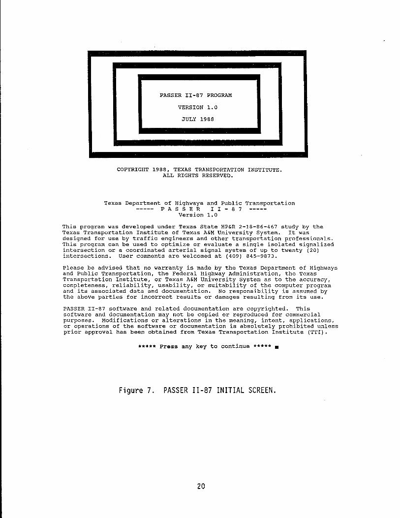
3. To run the program, type PASSER2 after the A> prompt and hit the <RETURN> key. The Disclaimer Screen will appear as shown in Figure 7.
4. Press any key and the PASSER 11-87 Confi gurat i on Routine screen will appear. The user may select from the choices shown in Figure 8.
Input Data Coding Using the Hard Disk System
The PASSER 11-87 program package comes preconfigured for use on a dual floppy drive system. Since the disk storage space on its logical A: disk is critical, this configuration restricts the use of the logical B: disk drive to only the user data input files. Since there is no B: drive in most hard disk systems, the program package may cause DOS errors or require the user to change the diskettes during the system operation. To make the PASSER II-87 system more flexible without compromising these operating system error checks, the microcomputer package has been provided wi th prei nsta 11 ed confi gurat ion routines. The user should install PASSER 11-87 on either the hard disk or the double-sided high-density type floppy disk when used in the IBM AT or 80386-based microcomputer systems.
19
PASSER II-87 PROGRAM
VERSION 1.0
JULY 1988
COPYRIGHT 1988, TEXAS TRANSPORTATION INSTITUTE. ALL RIGHTS RESERVED.
Texas Department of Highways and Public Transportation PAS S E R I I - 8 7
Version 1.0
This program was developed under Texas state HP&R 2-18-86-467 study by the Texas Transportation Institute of Texas A&M University System. It was designed for use by traffic engineers and other transportation professionals. This program can be used to optimize or evaluate a single isolated signalized intersection or a coordinated arterial signal system of up to twenty (20) intersections. User comments are welcomed at (409) 845-9873.
Please be advised that no warranty is made by the Texas Department of Highways and Public Transportation, the Federal Highway Administration, the Texas Transportation Institute, or Texas A&M University System as to the accuracy, completeness, reliability, usability, or suitability of the computer program and its associated data and documentation. No responsibility is assumed by the above parties for incorrect results or damages resulting from its use.
PASSER 1I-87 software and related documentation are copyrighted. This software and documentation may not be copied or reproduced for commercial purposes. Modifications or alterations in the meaning, intent, applications, or operations of the software or documentation is absolutely prohibited unless prior approval has been obtained from Texas Transportation Institute (TTl).
***** Press any key to continue ***** •
Figure 7. PASSER 11-87 INITIAL SCREEN.
20
Texas Department of Highways and Public Transportation PAS S E R I I - 8 7
Version 1.0
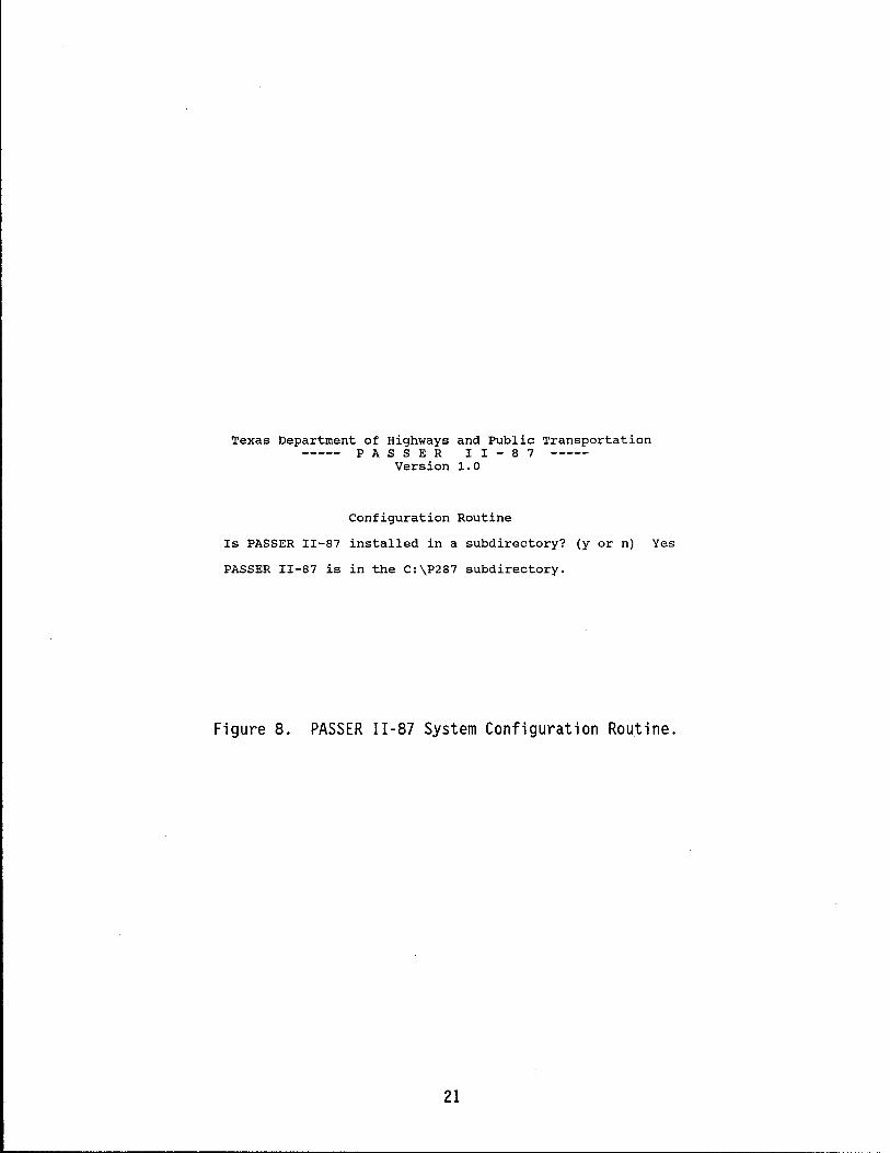
Configuration Routine
Is PASSER II-87 installed in a subdirectory? (y or n) Yes
PASSER II-87 is in the C:\P287 sUbdirectory.
Figure 8. PASSER 11-87 System Configuration Routine.
21
To install the PASSER 11-87 system on a hard disk machine or on a 1.2 MB or 1.44 MB floppy disk drive, the user should also consider the possible use of user-defined subdirectory structures for storing the PASSER 11-87 program by using the -MKDIR C:\P287- or -MD C:\P287-. Then, copy all files from both the distribution diskettes to this user hard disk directory by entering "COPY A:*.* C:\P287 /V·. This assumes that the A drive is a floppy disk drive and C is the hard disk as used in the IBM PC XT/AT or compatible microcomputer systems. Please refer to the DOS operating manual for operating the computer under different subdirectories.
When using PASSER 11-87 on a hard disk machine, the current subdirectory must be the one on which the PASSER 11-87 program files are stored, but data and output can be stored on or read from many different subdirectories or disk drives. At the C> prompt, enter -PASSER2·, and the system will display the disclaimer information. A configuration routine will then execute which will allow the user to specify any default subdirectory path for the program, together with input and output files on the floppy or hard disk microcomputer systems. When the user desires to store or read a data file, the user will be asked to define a path name to the file where the working files are stored. Each time the user wants to store the data sets, the system will also provide the user with the options for selecting a different subdirectory for optional data storage. If the subdirectory that the user selected for data storage has not been previously defined, the PASSER 11-87 system will help the user to create that part i cul ar subdi rectory. Otherwi se, the system will use the default subdirectory to store the user specified information.
If PASSER 11-87 must be moved by floppy disks from a hard disk system to other computer systems, the user must copy all the files listed previously to an empty floppy disk or disks in drive A. Then, enter "A:" to get the A> prompt. Next, enter "DEL HARDDISK.DAP and NDEL IOSPEC.DAP to convert the system default fil e storage path back to the floppy di sk system operation. The next time the user starts the system operation by typing in "PASSER2", the PASSER 11-87 system will be configurated according to user's instructions. If the user has a floppy disk system with high capacity drives, such as in the IBM AT or compatible 80286/80386 based microcomputers, the hard disk configuration should be used. In this case, the system can read and write all the data files from the default logged disk drive in the configuration file "HARDDISK.DAT". Please note, regardless of the file name, that the "HARDDISK.DAT" file will be generated for both the floppy disk based microcomputers as well as microcomputer systems equipped with hard disks.
STARTING THE TRAFFIC DATA INPUT SYSTEM
The following sections summarize the PASSER 11-87 system operation with the most basi c procedures. It ill ustrates to the users how to start the system, how to record the optional date and time, and the basic input/output keyboard instructions.
SYstem Overview
Two program di skettes are provided to use the input preprocessor and output postprocessor. The first one is the main diskette provided with the PASSER 11-87 program system which contains the input preprocessor and output
22
postprocessor program. The second diskette provides the main program and the optional help assistant menu of the PASSER II-87 system. It is highly recommended to use formatted bl ank di skettes to backup these program fil es before the users begi n to store the input data fi 1 es produced by the input preprocessor and output postprocessor and proceed with the analysis .
Start System
1. Insert input preprocessor and output postprocessor diskette in Drive A and data file diskette in Drive B.
2. Close drive doors.
3. Power up the system.
4. If system is already on, restart the system: press and hold down both the Ctrl and A It keys; then, press the Del key to restart the system.
Date and Time
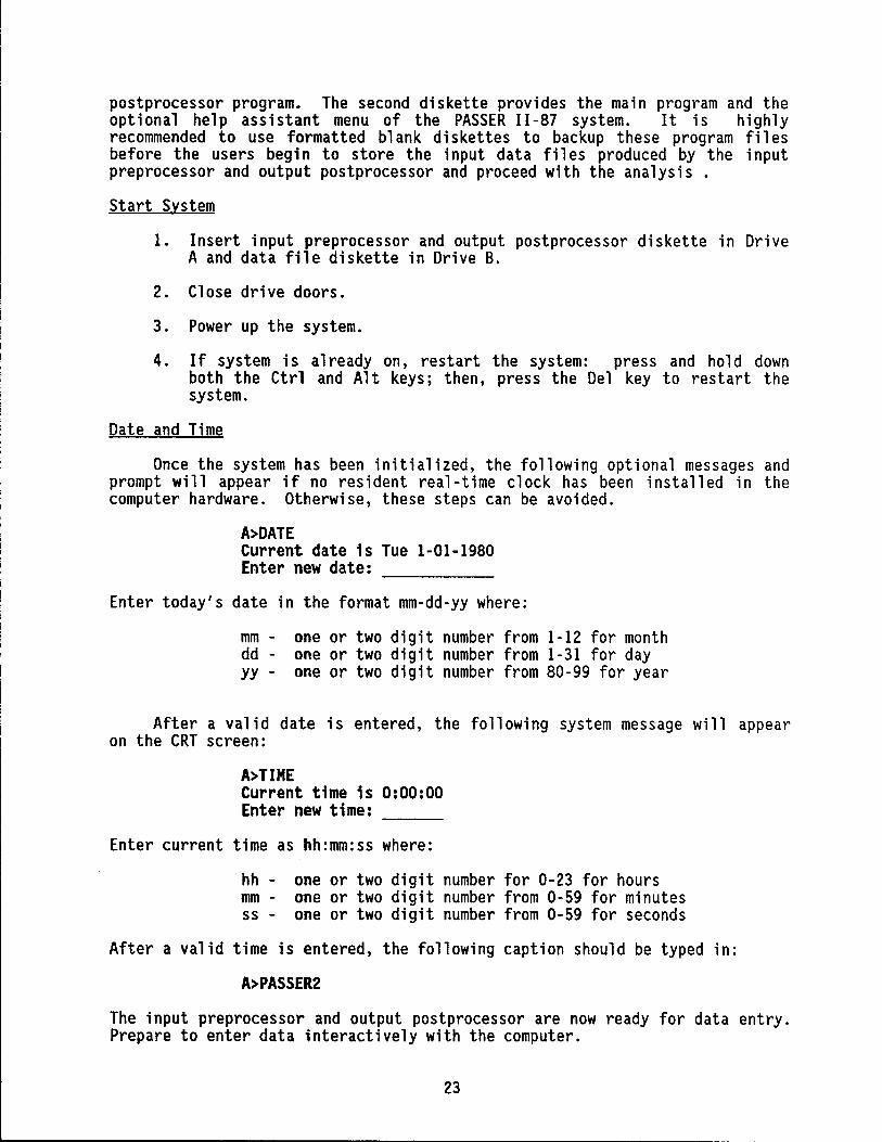
Once the system has been initialized, the following optional messages and prompt will appear if no resident real-time clock has been installed in the computer hardware. Otherwise, these steps can be avoided.
A>DATE Current date is Tue 1-01-1980 Enter new date: -----
Enter today's date in the format mm-dd-yy where:
mm - one or two digit number from 1-12 for month dd - one or two digit number from 1-31 for day yy - one or two digit number from 80-99 for year
After a valid date is entered, the following system message will appear on the CRT screen:
A>TIME Current time is 0:00:00 Enter new time: ---
Enter current time as hh:mm:ss where:
hh - one or two digit number for 0-23 for hours mm - one or two digit number from 0-59 for minutes ss - one or two digit number from 0-59 for seconds
After a valid time is entered, the following caption should be typed in:
A>PASSER2
The input preprocessor and output postprocessor are now ready for data entry. Prepare to enter data interactively with the computer.
23
Basic Keyboard Instructions
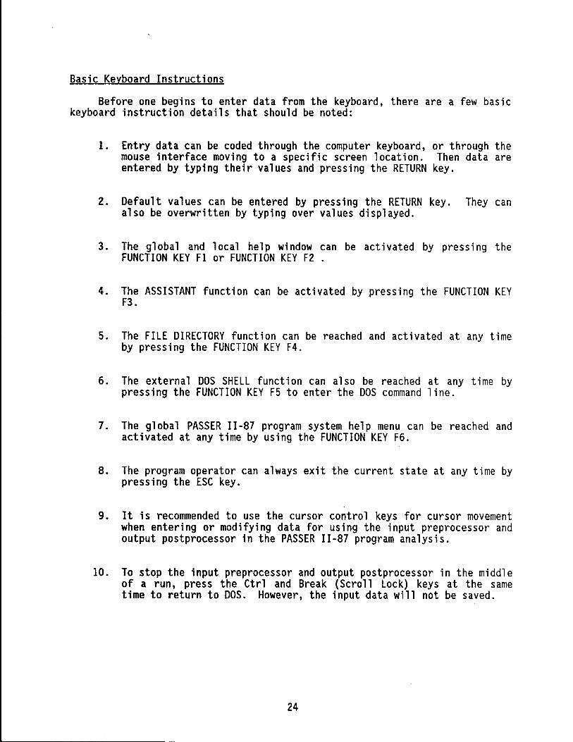
Before one begins to enter data from the keyboard, there are a few basic keyboard instruction details that should be noted:
1. Entry data can be coded through the computer keyboard, or through the mouse interface moving to a specific screen location. Then data are entered by typing their values and pressing the RETURN key.
2. Default values can be entered by pressing the RETURN key. They can also be overwritten by typing over values displayed.
3. The global and local help window can be activated by pressing the FUNCTION KEY Fl or FUNCTION KEY F2 .
4. The ASSISTANT function can be activated by pressing the FUNCTION KEY F3.
5. The FILE DIRECTORY function can be reached and activated at any time by pressing the FUNCTION KEY F4.
6. The external DOS SHELL function can also be reached at any time by pressing the FUNCTION KEY F5 to enter the DOS command line.
7. The global PASSER 11-87 program system help menu can be reached and activated at any time by using the FUNCTION KEY F6.
8. The program operator can always exit the current state at any time by pressing the ESC key.
9. It is recommended to use the cursor control keys for cursor movement when entering or modifying data for using the input preprocessor and output postprocessor in the PASSER 11-87 program analysis.
10. To stop the input preprocessor and output postprocessor in the middle of a run, press the Ctrl and Break (Scroll Lock) keys at the same time to return to DOS. However, the input data will not be saved.
24

-------------------------------~-
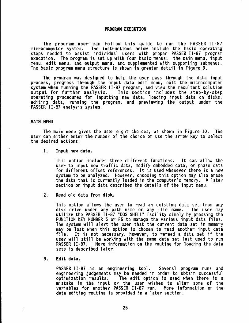
PROGRAM EXECUTION
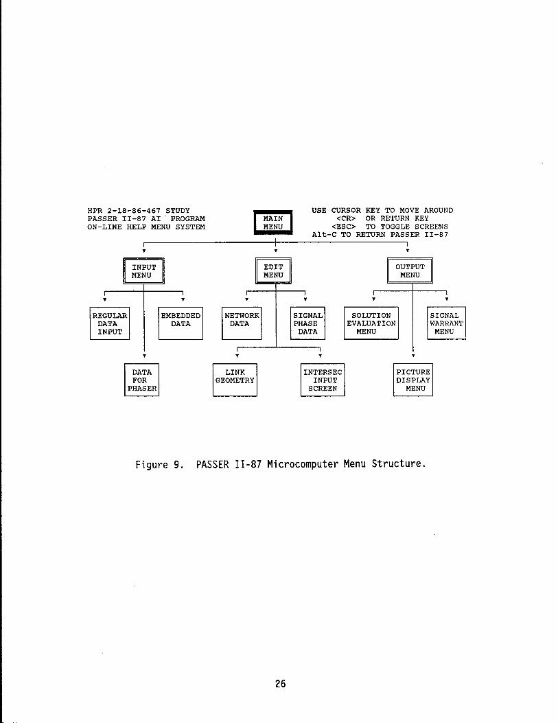
The program user can follow th is gu i de to run the PASSER II -87 microcomputer system. The instructions below include the basic operating steps needed to assist individual users with proper PASSER 11-87 program execution. The program is set up with four basic menus: the main menu, input menu,edit menu, and output menu, and supplemented with supporting submenus. The basic program menu structure is shown in greater detail in Figure 9.
The program was designed to help the user pass through the data input process, progress through the input data ed it menu, exit the mi crocomputer system when running the PASSER 11-87 program, and view the resultant solution output for further analysis. This section includes the step-by-step operating procedures for inputting new data, loading input data on disks, editing data, running the program, and previewing the output under the PASSER 11-87 analysis system.
MAIN MENU
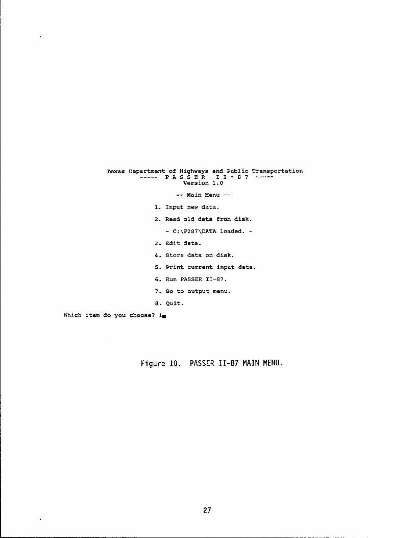
The main menu gives the user eight choices, as shown in Figure 10. The user can either enter the number of the choice or use the arrow key to select the desired actions.
1. Input new data.
This option includes three different functions. It can allow the user to input new traffic data, modify embedded data, or phase data for different offset references. It is used whenever there is a new system to be analyzed. However, choosing this option may also erase the data that is currently loaded in the computer's memory. A later section on input data describes the details of the input menu.
2. Read old data from disk.
This option allows the user to read an existing data set from any di sk dri ve under any path name or any fil e name. The user may utilize the PASSER II-87 "DOS SHELL" facility simply by pressing the FUNCTION KEY NUMBER 5 or F5 to manage the various input data files. The system will alert the user that the current data set in memory may be lost when thi s option is chosen to read another input data fi 1 e. It is not necessary, however, to reread a data set if the user will still be working with the same data set last used to run PASSER 11-87. More information on the routine for loading the data sets is described later.
3. Edit data.
PASSER 11-87 is an engineering tool. Several program runs and engineering judgements may be needed in order to obtain successful optimization results. The edit option is used when there is a mi stake in the input or the user wi shes to alter some of the vari abl es for another PASSER II -87 run. More i nformat i on on the data editing routine is provided in a later section.
25
HPR 2-18-86-467 STUDY PASSER 11-87 AI PROGRAM ON-LINE HELP MENU SYSTEM
,. ,.
REGULAR EMBEDDED DATA DATA INPUT
,.
DATA FOR
PHASER
,.
~ ~
I
NETWORK DATA
,.
LINK GEOMETRY
USE CURSOR KEY TO MOVE AROUND <CR> OR RETURN KEY
<ESC> TO TOGGLE SCREENS Alt-C TO RETURN PASSER 11-87
,.
,. ,. ,.
SIGNAL SOLUTION SIGNAL PHASE EVALUATION WARRANT
DATA MENU MENU
,. ,.
INTERSEC PICTURE INPUT DISPLAY
SCREEN MENU
Figure 9. PASSER 11-87 Microcomputer Menu Structure.
26
~~~~- ~-------~--
Texas Department of Highways and Public Transportation PAS S E R I I - 8 7
Version 1.0
Main Menu
1. Input new data.
2. Read old data from disk.
- C:\P287\DATA loaded. -
3. Edit data.
4. store data on disk.
5. Print current input data.
6. Run PASSER II-87.
7. Go to output menu.
8. Quit.
Which item do you choose? 1.
Figure 10. PASSER 11-87 MAIN MENU.
27
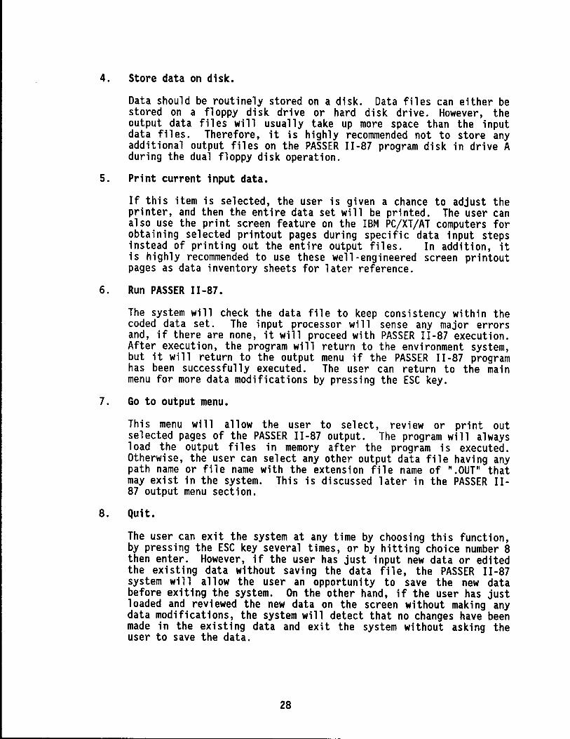
4. Store data on disk.
Data should be routinely stored on a disk. Data files can either be stored on a floppy disk drive or hard disk drive. However, the output data fil es will usua 11 y take up more space than the input data files. Therefore, it is highly recommended not to store any additional output files on the PASSER 11-87 program disk in drive A during the dual floppy disk operation.
5. Print current input data.
If this item is selected, the user is given a chance to adjust the printer, and then the entire data set will be printed. The user can also use the print screen feature on the IBM PC/XT/AT computers for obtaining selected printout pages during specific data input steps instead of printing out the entire output files. In addition, it ish i gh 1 y recommended to use these well-eng i neered screen pri ntout pages as data inventory sheets for later reference.
6. Run PASSER 11-87.
The system will check the data file to keep consistency within the coded data set. The input processor will sense any major errors and, if there are none, it will proceed with PASSER 11-87 execution. After execution, the program will return to the environment system, but it wi 11 return to the output menu if the PASSER I I -87 program has been successfully executed. The user can return to the main menu for more data modifications by pressing the ESC key.
7. Go to output menu.
This menu will allow the user to select, review or print out selected pages of the PASSER 11-87 output. The program will always load the output fil es in memory after the program is executed. Otherwise, the user can select any other output data file having any path name or file name with the extension file name of ".OUT" that may exist in the system. This is discussed later in the PASSER 11-87 output menu section.
8. Quit.
The user can exit the system at any time by choosing this function, by pressing the ESC key several times, or by hitting choice number 8 then enter. However, if the user has just input new data or edited the exi st i ng data wi thout savi ng the data fil e, the PASSER II -87 system will allow the user an opportunity to save the new data before exiting the system. On the other hand, if the user has just loaded and reviewed the new data on the screen without making any data modifications, the system will detect that no changes have been made in the exi st i ng data and exi t the system wi thout aski ng the user to save the data.
28
INPUT MENU
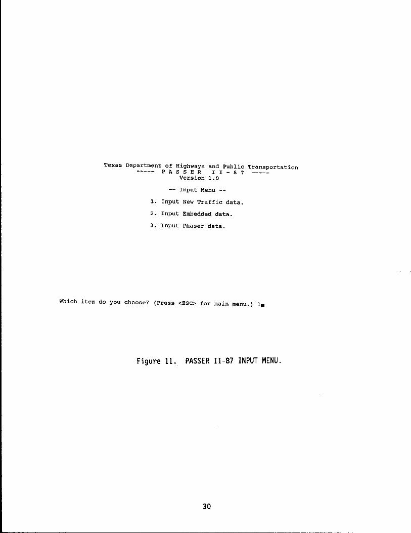
The new input menu has three (3) choices, as shown in Figure 11, that allow the user to input new traffic data, change embedded data for the whole system, and change phaser data to allow for various ways to reference signal timing parameters. When this desired choice is entered, the program will lead the user to input the data requ i red for PASSER I I -87 program execut ion. The input requires most of the same data as needed in the mainframe PASSER 11-87 program but in a slightly different order to ease the data entry process. If desired, the user can also download the PASSER 11-87 input data deck from the mainframe computer systems and read the existing data set for executing the PASSER 11-87 microcomputer environment system. The options in the input menu ask the user to enter the arterial system, geometric data, traffic volume, and signal control data for the arterial system as required in the original mainframe "Arterial Header Card," "Intersection Header Card," "Intersection Detail Card," new "Embedded Data Card," and new "Phaser Data File." After completing the data input, the user can either modify the input data, execute the program, or save the data files, as desired. On the other hand, the user may chose to input new data or add more intersections to the existing arterial signal system. The data edit routine may be selected to modify existing coded data or add further input data to the current data file. A new menu, the edit menu, appears to give the user eight (8) choices. If the user desires to return to the input menu to restart the new data input, this can be done by returning to the main menu and selecting the input new data option again by selecting the proper number.
New Traffic Data Input
The input rout i ne may be act i vated by enteri ng a "1" on the rna in menu. This same input routine will also be automatically activated when the user chooses to add new intersect ions to the exi st i ng system form the ed it menu. There are two restrictions which are built into the system that should be noted:
1. All traffic movement data must be entered and will be returned using the NEMA phasing numbers, shown previously in Figure 2, as defined in the new Traffic Control Systems Handbook.
2. If only one intersection is used in the input data, it will be analyzed in default as an isolated intersection. Otherwise, a progression solution run will be assumed.
The first section of the input new data menu corresponds to the Arterial Header Card as used in preparing the mainframe PASSER 11-87 input decks. If on 1 y one intersect ion is to be input, the user will be as ked for on 1 y one cycle length, since PASSER II-87 can only analyze one cycle length in an isolated operation at one time. The user will not be asked to provide i nformat i on about progress ion ope rat ions. The new data input is made by selecting Option 1 by typing 1 and hitting <RETURN>. The next message on the screen will be "Abandon existing input data? (y or n): Type y and <RETURN>. Then, the computer will run one-by-one through the arteri ali nput data as shown in Figure 12. The appropriate response should be typed in corresponding to the ARTERIAL HEADER information. After specifying the system information, the next step is to provi de the input data for each intersect ion, start i ng with Intersection number 1.
29
"-----------------------------------
Texas Department of Highways and Public Transportation PAS S E R I I - 8 7
Version 1.0
Input Menu --
1. Input New Traffic data.
2. Input Embedded data.
3. Input Phaser data.
Which item do you choose? (Press <ESC> for main menu.) 1.
Figure 11.. PASSER II-a7 INPUT MENU.
30
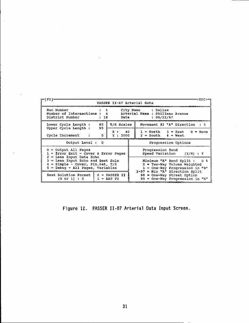
--- -- --- -------------------------
F(F2] <ESC>= PASSER II-87 Arterial Data
Run .Number : 1 city Name : Dallas Number of Intersections : 4 Arterial Name : Skillman Avenue District Number : 18 Date : 06/22/87
Lower Cycle Length : 85 T/S Scales Movement #2 "A" Direction : 3 Upper Cycle Length : 95
X : 40 1 = North 3 = East 0 = None Cycle Increment : 5 Y : 2000 2 = South 4 = West
Output Level : 0 Progression Options
0 = output All Pages Progression Band 1 = Error Exit - Cover & Error Pages Speed Variation (Y/N) : Y 2 = Less Input Data Echo 3 = Less Input Echo and Best Soln Minimum "A" Band split : 0 % 4 = Simple - Cover, Pin. Set, T/S 0 = Two-Way Volume Weighted 5 = Debug - All Pages, Variables 1 = One-Way Progression in "B"
2-97 = Min "A" Direction Split Best Solution Format I 0 = PASSER II 98 = One-Way Street option
(0 or 1) : 0 1 = AAP P2 99 = One-Way Progression in "A"
Figure 12. PASSER 11-87 Arterial Data Input Screen.
31
As the second part of data input, the system will ask for the name of each cross street as well as the traffic volume, saturation flow and minimum phase for each NEMA phase movement. A NEMA traffic movement display input screen will assist the user to input the basic traffic movement, saturation flow, and minimum phase according to their corresponding positions as shown in Figure 13. In addition, a series of user input ASSISTANT functions can be activated by pressing FUNCTION KEY NUMBER 3 or F3 to access the saturation flow calculations as in Chapter 9 of the 1985 Highway Manual (HCM). For every signalized intersection, the computer will ask the name of the cross street and then ask for the foll owi ng data for each movement: vol umes, saturation flows, and minimum phase times. The data for each movement are input interactively and the movements appear on the screen according to the NEMA numbering system. Figure 13 shows the data for all the movements input for intersection MOCKINGBIRD based on the data provided in the Intersection Data Form. It should be noted that if a zero has been chosen for the volume input, then the program will not require the user to input the remaining saturation flows and minimum phase times.
In the third part of the input data section, the program will ask the user to choose the appropriate signal phasing patterns to be analyzed by toggl ing either the ENTER or the RETURN key as shown in Figure 14. In the coding of the Arterial Phasing, the program displays on the screen all the possible phasing sequence combinations based on the input volumes. The PASSER 11-87 input/output processor system only uses those signal phase patterns which are logically compatible with the input traffic movement vol umes the user has just entered accordi ng to the system's default phase sequence function. The user may also ask the system to recommend the allowable phasing selections by pressing the FUNCTION KEY NUMBER 3 or F3. However, the user can also select some other phase sequences not defined by the normal phase sequence by choos i ng the speci a 1 phase opt ion. Fi gure 14 illustrates the phasing for Intersection number 1 (MOCKINGBIRD). The user must move the cursor to the desired phasing pattern and select by pressing <RETURN> to toggle "V" to each desired menu selection as shown in Figure 14. A maxi mum of four poss i b 1 e phas i ng sequences can be spec ifi ed. Pl ease note that if yes is the response to a "with overlap" question, the program assumes that the "without overlap" option is unacceptable. For coding the Cross Street Phasing, the program displays on the screen all the possible phasing arrangements for the cross street based on the input volumes. However, only one phasing pattern is allowed for the cross street. The program will allow the user to select the acceptable phasing pattern. The user should move the cursor to the allowable desired phasing pattern and press <RETURN> to select as shown in Figure 14. The coding of the signalized intersection will be repeated for each intersection. Please use the information described earlier to enter data for the remaining intersections of the arterial street system.
The fourth part of new input data wi 11 ask the user to provi de the geometry data for the intersection approaches or links of the arterial signal system as if they are filling up a data inventory table, as shown in Figure 15. It is used to input data on consecutive intersection spacing and progression design speed between intersections for each direction, as well as for any desirable queue clearance time, if this option is desired. As indicated, the system asks for distance and speed for each intersection for each direction. Then, the same link data will be generated as the default to the other travel direction. Note that the queue clearance option is not specified or used in this example.
32
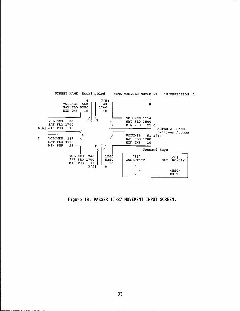
5[5]
2
STREET NAME Mockingbird NEMA VEHICLE MOVEMENT INTERSECTION 1
VOLUMES SAT FLO MIN PHS
VOLUMES SAT FLO MIN PHS
4 VOLUMES 568 SAT FLO 5250 MIN PHS 16
7[5] 43
1700 10 L
r / \ v 88 1700
10 1 /
> 287 \ 3500
21
l VOLUMES SAT FLO MIN PHS
240 1700
10
r 1 \ /
\ <
/
1560 5250
16 3[5] 8
N
VOLUMES 1114 SAT FLO 3500 MIN PHS 21 6
VOLUMES SAT FLO MIN PHS
ARTERIAL NAME Skillman Avenue
51 1[5] 1700
10
Command Keys
[F3] [F2] ASSISTANT BAY NO-BAY
> <ESC> v EXIT
Figure 13. PASSER 11-87 MOVEMENT INPUT SCREEN.
33
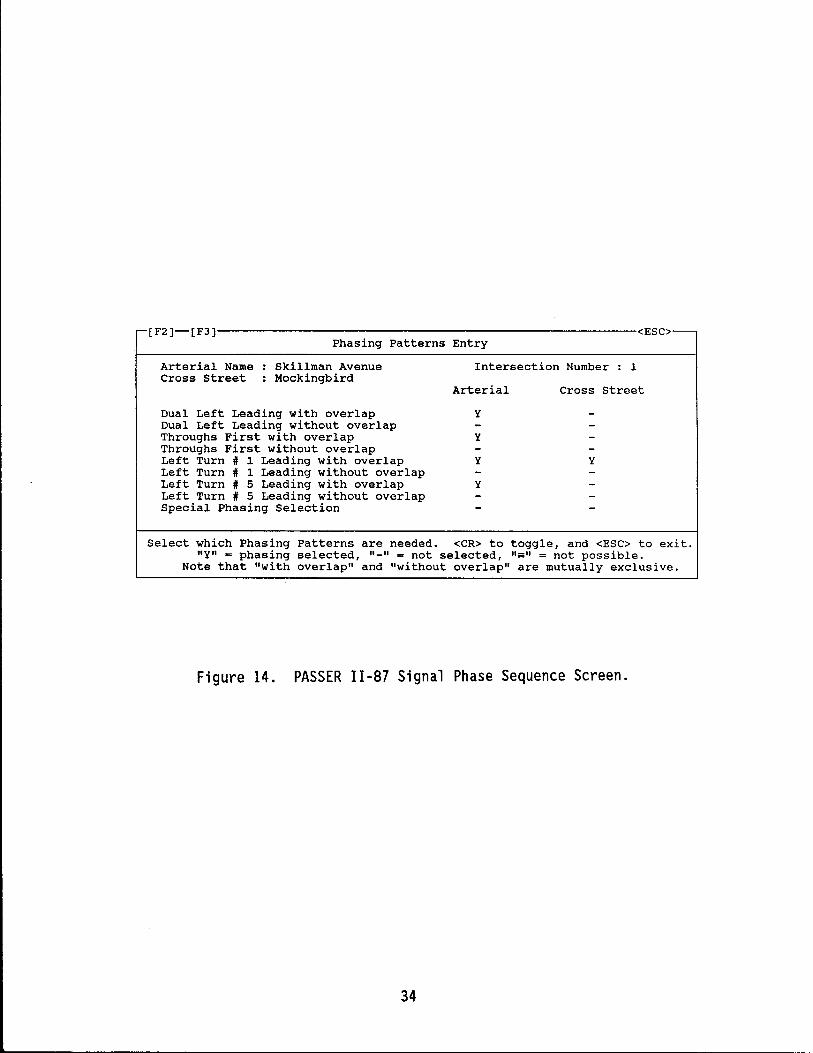
r-[F2)--[F3)------------------------------------------------------------<ESC>---Phasing Patterns Entry
Arterial Name Cross street
Skillman Avenue Mockingbird
Dual Left Leading with overlap Dual Left Leading without overlap Throughs First with overlap Throughs First without overlap Left Turn # 1 Leading with overlap Left Turn # 1 Leading without overlap Left Turn # 5 Leading with overlap Left Turn # 5 Leading without overlap special Phasing Selection
Intersection Number : 1
Arterial Cross street
y
y
y y
y
Select which Phasing Patterns are needed. <CR> to toggle, and <ESC> to exit. lIy" = phasing selected, "-" = not selected, "",," = not possible.
Note that "with overlap" and "without overlap" are mutually exclusive.
Figure 14. PASSER 11-87 Signal Phase Sequence Screen.
34
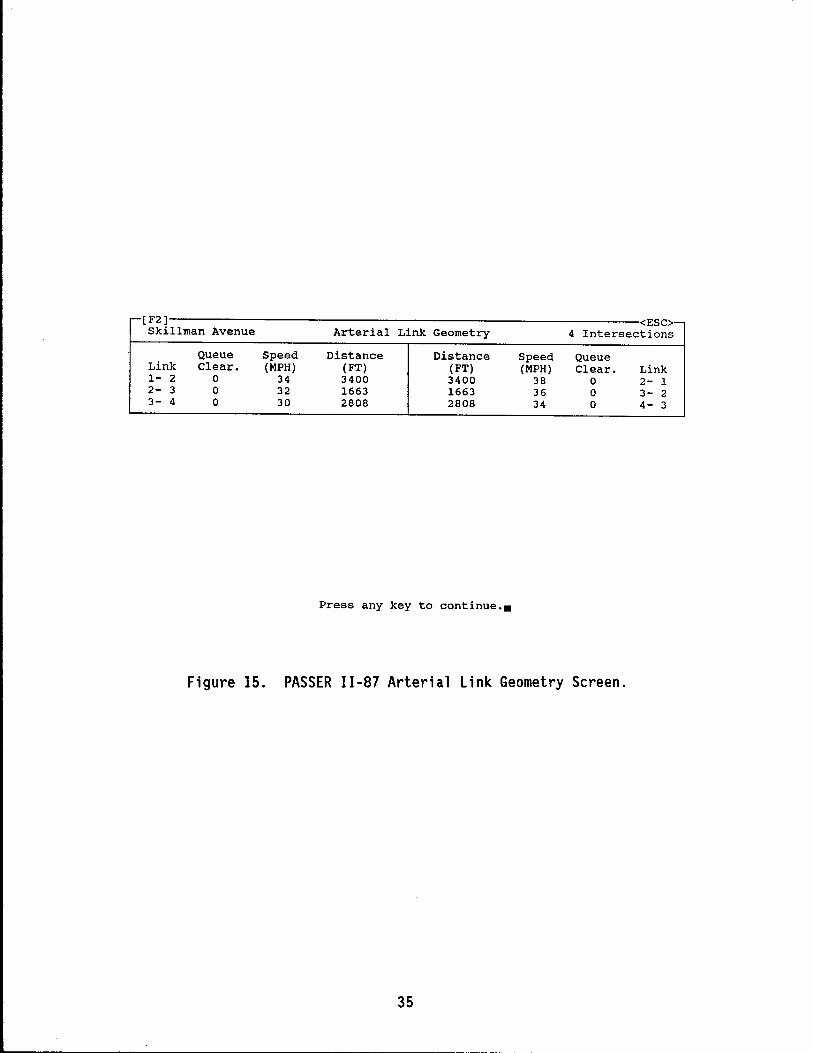
r-[F2) <ESC> Skillman Avenue Arterial Link Geometry 4 Intersections
Queue Speed Distance Distance Speed Queue Link Clear. (MPH) (FT) (FT) (MPH) Clear. Link 1- 2 0 34 3400 3400 38 0 2- 1 2- 3 0 32 1663 1663 36 0 3- 2 3- 4 0 30 2808 2808 34 0 4- 3
Press any key to continue ••
Figure 15. PASSER 11-87 Arterial Link Geometry Screen.
35
When the above data input steps are completed, the program will return to the main input menu shown in Figure 11. Selecting Item 5 will provide a printout of the coded input data to check against the data file being entered.
Embedded Data Input
In response to the expressed user desire to be able to modify embedded data used in PASSER II, new features have been added to the program to let users adjust all the embedded data. The default embedded data sets, as shown in Figure 16, have also been prepared for user information. Be aware that once the embedded data is changed, it will remain that way for subsequent data sets. These embedded data include traffic controller type, ideal saturation flow rate, analysis period, number of left turn sneakers, individual phase lost time, combined left turn phase reference, delay level-of-service evaluation, total delay adjustment factor, basic HCM delay criteria, permitted left turn models, and left turn model coefficients. The embedded data, as modified by the user, will also be printed out in the input data echo output.
TRAFFIC CONTROL TYPE The user has the choice of selecting either pretimed control (P) or actuated control (A) for the delay calculations of different signal timings. The selection of actuated control will provide an estimated 0.85 percent of the delay that would have been estimated for pretimed signal control, as suggested in the 1985 HCM. The default assumes pretimed signal control.
IDEAL SATURATION FLOW The default ideal saturation flow rate is 1800 vehicles per hour of effective phase per lane or vphgpl as used in the 1985 HCM. The default range in PASSER 11-87 is from 1500 to 2400 vphgpl.
ANALYSIS PERIOD The default time period for PASSER 11-87 analysiS is 15 minutes, the same value used in the 1985 HCM. The allowable range is from 15 to 300 minutes, or 0.25 to 5 hours.
NUMBER OF SNEAKERS The default value for the number of sneakers making left turns from a left turn lane following the yellow signal to red is 2.0 vehicles per yellow change to red. Its range is 1.0 to 3.0 vehicles.
PHASE LOST TIME The default value of all individual signal phase lost times is 4.0 seconds. It ranges from 3.0 to 5.0 seconds per phase.
LEFT TURN P + P REFERENCE For the different protected-plus-permitted "combined phase" left turn phase operations the user can choose either the "A" for approach-based or "R" for ring-based designation, as recommended by the Manual of Uniform Traffic Control Devices (MUTCD), or the experimental practice implemented in Dallas, respectively. In "A", the approach-based operation, the left turn permitted phase usually ends earlier than the "R" or the ring-based operation. The default is the "A" designation or approach-based.
LOS DELAY CRITERIA The user has the choice of using either the total delay evaluation (T) or stopped delay evaluation (S) as used in the 1985 HCM evaluation. The default level of service evaluation is the total delay evaluation as used in the existing PASSER II analysis.
36
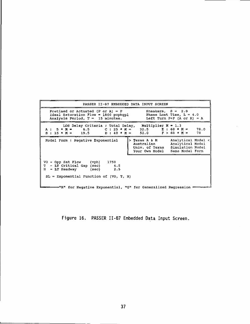
PASSER II-87 EMBEDDED DATA INPUT SCREEN
Pretimed or Actuated (P or A) = P Sneakers, S = 2.0 Ideal Saturation Flow = 1800 pcphgpl Phase Lost Time, L = 4.0 Analysis Period, T = 15 minutes. Left Turn P+P (A or R) = A
LOS Delay criteria A: 5 * M 6.5 B : 15 * M 19.5
==============================91 Total Delay,
C : 25 * M D : 40 * M
Multiplier M = 1.3 32.5 E 60 * M = 52.0 F > 60 * M =
78.0 78
Model Form Negative Exponential > Texas A & M Australian Univ. of Texas Your Own Model
Analytical Model < Analytical Model Simulation Model Same Model Form
VO - Opp Sat Flow (vph) T - LT Critical Gap (sec) H - LT Headway (sec)
1750 4.5 2.5
SL = Exponential Function of (VO, T, H)
1l=:==="N" for Negative Exponential, "G" for Generalized Regression =====!J
Figure 16. PASSER 11-87 Embedded Data Input Screen.
37
TOTAL DELAY MULTIPLIER PASSER 11-87 uses a default multiplier for converting the default stopped delay to total delay as recommended in the 1985 HCM. The default multiplier is either 1.3 for adjusting to total delay evaluation or 1.0 for using stopped delay evaluation. However, the user can also change this value, ranging from 1.0 to 1.3, if desired at some future date.
BASIC HCM DELAY CRITERIA The user has two ways to adjust the del ay threshold for the level-of-service evaluation to be used in the PASSER II -87 signal delay est i mat ion. At fi rst, one can change the multiplier of the stopped delay to the total delay to adjust all of the de 1 ay thresholds in the same magn i tude as descri bed in the total delay multiplier. In addition, one can also separately change the individual delay criteria. All the delay thresholds used in the evaluation will be output in the PASSER 11-87 embedded data report for detailed examination by the user. The basic delay thresholds for the default level-of-service evaluation are:
A (At) = 5 * Multiplier, range from 0 to 10.
B (Bt) = 15 * Multiplier, B > A and B < 90.
C (Ct) = 25 * Multiplier, C > Band C < 90.
0 (Ot) = 40 * Multiplier, o > C and 0 < 90.
E (Et) = 60 * Multiplier, E > 0 and E < 90.
F (Ft) > 60 * Multiplier, F = E.
PERMITTED LEFT TURN CAPACITY MODEL The user has two choi ces for designating the desired opposing traffic flow model used in permitted left turn capacity analysis,"N" for the Negative Exponential Model or "G" for the Generalized Regression Model. The default model is the Negative Exponential - Texas A&M Analytical Model. After the user selects the model, the program wi 11 automatically change the parameters for each mode 1 . If the user wants to use another model, one can select the preferred model form, collect the site specific traffic information, and input all the needed model coefficients.
The Negative Exponential Models include the following:
1. Texas A & M 2. Australian 3. Univ. of Texas 4. Your Own Model
Analytical Model Analytical Model Simulation Model Same Model with User specified coefficient.
The Generalized Regression Models include the following:
1. HCM-Signalized Analytical Model 2. HCM-Unsignalized Analytical Model 3. Univ. of Minn. Regression Model 4. Ohio State Univ. Regression Model 5. Your Own Model Same Model with User specified coefficient.
38
Phaser Data Input
The program provides the user with two default, alternative ways to specify the phase interval setting reports (PIN.SET) through the input screen as shown in Figure 17. Two sets of PIN.SET reports will be generated. All the help messages will be displayed on the bottom half of the screen. The default value for Master Intersection and Reference Intersection will be 1 or the first intersection of the arterial the system. The user can also change the offset reference from default intersection number 1 to any intersection in the current data set. Reference offset will be any value from 0 to the lower cycle length, and the default is O. The movement for reference can be chosen from 0, 2, and 6, and the default is "0" or the beginning of the arterial phase. For reference point, the user can select the beginning of the phase or the end of that part i cul ar phase. The default offset reference is at the beginning of main street green, or the "Barrier Point" for dual-ring controllers.
COMMENT LINE The user can request the program to use these comments in this particular data file to interpret the basic set of optimized PASSER 11-87 signal timing parameters. This comment line, made up of two lines with a maximum of 75 characters each, is provided for the user to place at the remark lines for every set of criteria used to interpret the signal timing solutions. The comment line will also be printed in the signal controller phase interval setting report (PIN.SET).
MASTER INTERSECTION The arterial's progression offset timing base is its "master" intersection, if not interconnected with a larger system. In PASSER II, a Master Intersection designation is used to refer to the zero offset coordination. The default master intersection is always set to be the first signalized intersection in the arterial street system.
REFERENCE INTERSECTION The reference intersection is the secondary offset reference point, used only if the arterial under analysis has its timing plan integrated (interlocked) into an existing coordinated timing plan. This is defined by the crossing arterial street at the "Reference Intersection." The designation of the Reference Intersection can supersede the speci ficat i on of the Master Intersect ion. The default reference intersection is also the first intersection in the signal system.
REFERENCE OFFSET This is the system reference offset for all relative offset calculations. PASSER II-87 will adjust all the optimum signal timing settings with respect to this particular reference offset point. The defaul t value of the reference offset is zero. The a 11 owab 1 e range is from zero to the entire cycle of the lower cycle length.
MOVMNT The "MOVMNT" or movement is specified for all relative offset calculations. The allowable traffic movements could be either at the beginning of the arterial phasing "0", the "NEMA 2," or the "NEMA 6" movements. The default is the start of the arterial phasing or "0".
REFERENCE POINT The reference point is the point to which all the reference offsets are referring and with which they are calculated. It can be at either the beginning or end of the selected referenced phase. The default is at the beginning of the arterial phasing.
39
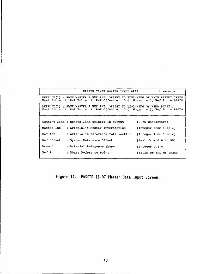
PASSER 11-87 PRASER INPUT DATA 2 Records
DEFAULT (1) : SAME MASTER & REF INT, OFFSET TO BEGINNING OF MAIN STREET GREEN Mast Int = 1, Ref Int = 1, Ref Offset = 0.0, Movmnt = 0, Ref Pnt = BEGIN
DEFAULT (2) : SAME MASTER & REF INT, OFFSET TO BEGINNING OF NEMA PHASE 2 Mast Int = 1, Ref Int = 1, Ref Offset = 0.0, Movmnt = 2, Ref Pnt = BEGIN
comment Line Remark line printed in output [0-75 Characters]
Master Int Arterial's Master Intersection [Integer from 1 to 4]
Ref Int Arterial's Reference Intersection [Integer from 1 to 4]
Ref Offset System Reference Offset [Real from 0.0 to 85]
Movmnt Arterial Reference Phase [Integer 0,2,6]
Ref Pnt Phase Reference Point [BEGIN or END of phase]
Figure 17. PASSER 11-87 Phaser Data Input Screen.
40
L......-______________________________ ~ __ ~ ___ _
EDIT MENU
The edit routine is chosen by entering a 3 on the main menu. A new data editing menu will appear which will give the user eight (8) choices of data to edit, as shown in Figure 18. If the user wants to return to the main menu for either modifying the embedded data, loading another data set, or storing the data set on the disk, the user can press the ESC key.
1. Edit general network data.
The data edit routine will modify the portion of the data which is on the Arterial Header Card or that pertains to the total arterial system for regul ar PASSER II input data . All the data can be changed except the total number of intersect ions. The number of intersections in the general network data must be changed by adding or deleting particular intersections in the arterial system of the existing coded data set.
2. Edit intersection movement data.
The user will be asked which intersection is to be edited and then the user can change the volumes, saturation flows and minimum phases for all intersection movements from a graphic intersection display. In addition, the analysis procedure similar to and beyond the 1985 HCM analysis can also be performed through the ASSISTANT function. The user must use this option to input the necessary data for coding or specifying the different types of left turn signal treatments of existing PASSER 11-87 data sets. On the other hand, current PASSER II-84 users can still take advantage of the graphical input data screen layout for coding the data input without having to use the ASSISTANT function at all. The arterial name and the intersection orientation direction will be displayed according to the user input in the arterial system data. It is highly recommended that the print screen capability of the IBM PC/XT/AT microcomputers be used to pri nt the screen for data inventory purposes. The details of the ASSISTANT function will be discussed in a later section.
3. Edit intersection phasing data.
The user will be asked which intersection is to be edited and then select the phasing sequences for both the arterial and the cross street. The system will display all the allowable signal phasing sequences for both the main street and cross street traffic movements. For which, the selection of Phasing Patterns are needed. As noted, three different symbols will be used in this intersection phasing input data screen. "Y" represents the phasing selected, "=" represents the phase sequences not all owed by the system, and "-" stands for the allowable phase sequence. ASSISTANT function F3 can display the "allowable" selection. The user can use the Return key <CR> to toggl e, and <ESC> to exi t. Note that "wi th overl ap" and "without overlap" are mutually exclusive. However, if normal phasing patterns are not enough, the user can toggle the "Special Phasing" and then select phasing patterns not defined in the "Allowable" phase selection tables.
41
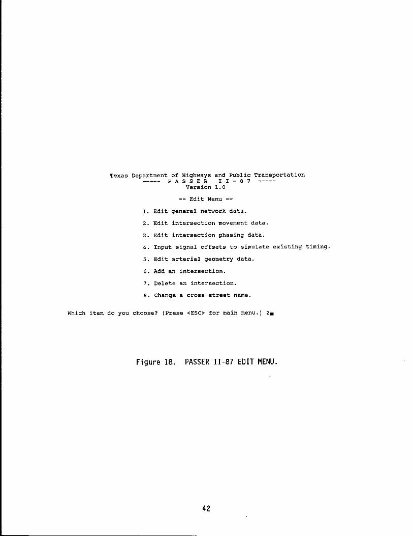
Texas Department of Highways and Public Transportation PAS S E R I I - 8 7
Version 1.0
-- Edit Menu --
1. Edit general network data.
2. Edit intersection movement data.
3. Edit intersection phasing data.
4. Input signal offsets to simulate existing timing.
5. Edit arterial geometry data.
6. Add an intersection.
7. Delete an intersection.
8. Change a cross street name.
Which item do you choose? (Press <ESC> for main menu.) 2.
Figure 18. PASSER 11-87 EDIT MENU.
42
4. Input signal offsets to simulate existing timing.
Each intersection may have the existing or different offset values during the simulation study. This menu selection will not only allow the user to input the existing offsets of each intersection to be evaluated but will also allow the user to select the optimization or simulation analysis. The user can store the existing offsets and still ask the program to perform the optimization run. The offsets, as input, will be adjusted to the lower cycle length input.
5. Edit arterial geometry data.
All of the intersection distance, travel speed, and queue clearance for those links in the system will be shown, and the user can change any of them. To specify which link is to be changed, the cursor should first be moved to the number of the intersection which starts the link and then the user can modify the data for that particular signalized intersection.
6. Add an intersection.
If the user wishes to add an intersection, this item should be sel ected. The user then sees ali st of cross street names. The number of the intersection which the new intersection comes before should be entered. A "I" should be selected if the user wants to add it at the beginning of the system. If the user has already reached the maximum number of intersections, no more can be added.
7. Delete an intersection.
The user can select the spec i fi c number of the signal i zed intersection to be deleted from a list of cross street names. However, if there is only one intersect i on currently in the data set, the user will not be allowed to delete it.
8. Change a cross street name.
Any of the cross street names can be changed using this routine as if using any word processor. The user simply selects the number of the part i cul ar intersect i on and changes the name by typi ng in the new name of the cross street.
DATA INPUT ASSISTANT FUNCTIONS
One new feature in PASSER 11-87 is the addition of the DATA INPUT ASS I STANT FUNCTION for ass i st i ng users to input the movement related information, such as the traffic movement volume (VOLUME), saturation flow rate (SAT FLO), and the minimum phase time (MIN PHS). Among them, the most practical enhancement of the PASSER 11-87 input/output processor is the programming ASSISTANT that allows users to calculate the saturation flow rate fo 11 owi ng anal ys is procedures s i mil ar to and beyond those used in the 1985 Hi ghway Capaci ty Manual (HCM) (~). The recommended sequence and usage of these different input data features, as used in the input data ASSISTANT function, are illustrated in Figures 19 through 21 and described as follows:
43
Left Turn Bay
The first problem that the user should resolve is whether there exists a left turn bay on each of the intersection approaches. As shown in Figure 11, the user shou1 d i dent i fy the presence or absence of a 1 eft turn bay or ded i cated 1 eft turn 1 ane by togg1 i ng the FUNCTION KEY 2 or F2 until the correct left turn treatment is displayed on that particular approach. The difference between the BAY and NO BAY conditions will be shown by the shading of the VOL SAT FLO and Min PHS for that movement or in the lower right hand of the command box.
Traffic Volume
The next action is to enter the traffic volumes for each approach to the intersection as shown in Figure 19. The use of the ASSISTANT function will allow the user to calculate the traffic volumes and adjust for the peak hour factors. When the peak left-turn volume is not greater than two vehicles per cycle, there is usually no need to provide a protected left-turn phase.
Volume Calculation
There are two distinct features in the PASSER 11-87 program for handling the vari ous 1 eft turn treatments for those cases wi th or without protected left turn bays. First, the program will provide the user with the capability to des ignate the protected 1 eft turn bay whil e i nputt i ng the correspondi ng left turn traffic movements. Then, the program will automatically generate the appropriate type of left turn signal treatments and prompt the user with the necessary actions in the ASSISTANT window according to the input data. Separate treatments have been made in the PASSER 11-87 program to account for the di fference in the 1 eft turn movements and the through traffi c movements with or without using the protected left turn bay.
LEFT TURN MOVEMENT (I, 3, 5, 7)
1. If the MIN PHS equals 0, then the program will assume the permitted green operation. No separate protected phase will be provided.
2. If the MIN PHS is greater than 0, then the program will ask "LEFT TURN PROTECTED ONLY?". If the answer is yes, then the program will provide a protected-only phase; otherwi se, the program wi 11 assume that a combi ned phase, havi ng a protected phase combi ned wi th a permitted phase, will be used in the analysis.
After this, the program will ask for LEFT TURN TRAFFIC. If there is a bay, then left turn volume will be stored individually. Otherwise, the system will add the left turn traffic volume into through movement volume but keep a separate count of the left turn traffic being input by the user. Therefore, the numbers of the left turn traffic will still be shown on the screen with reverse color. If there is a bay, the program will ask the user to input the PEAK HOUR FACTOR, with a default value of 1, and the final LEFT TURN TRAFFIC = LEFT TURN TRAFFIC/PEAK HOUR FACTOR.
As indicated in Figure 19, a unique number will be displayed in the brackets or "[ ]" to designate the particular left turn signal treatments to be used in the analysis. The same "Left Turn Signal Treatment" or the
44
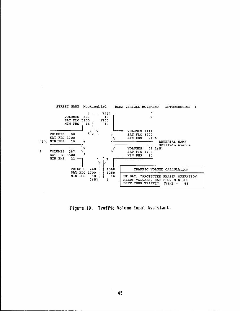
STREET NAME Mockingbird NEMA VEHICLE MOVEMENT INTERSECTION 1
4 7[5] VOLUMES 568 43
L N SAT FLO 5250 1700 MIN PHS 16 10
/ \ VOLUMES 1114 VOLUMES 88 v r SAT FLO 3500 SAT FLO 1700 \ MIN PHS 21 6
5[5] MIN "PHS 10 1 < ARTERIAL NAME I Skillman Avenue
> / VOLUMES 51 1[5] 2 VOLUMES 287 \ SAT FLO 1700
SAT FLO 3500 MIN PHS 10 MIN PHS 21
l r 1 \ I
VOLUMES 240 1560 TRAFFIC VOLUME CALCULATION SAT FLO 1700 5250 MIN PHS 10 16 LT BAY, "PROTECTED PHASE" OPERATION
3[5] 8 NEED: VOLUMES, SAT FLO, MIN PHS LEFT TURN TRAFFIC (VPH) = 88
Figure 19. Traffic Volume Input Assistant.
45
"NPP" values will also be displayed both in the Input Data Echo printout (INPUT.DTA) and the Best Solution printout (BEST.SOLN) of the PASSER 11-87. In particular, NPP identifies the different left turn signal treatments as input by the user and explained in the ASSISTANT window as:
NPP = 1 - without left turn bay, permitted NPP = 2 - without left turn bay, protected NPP = 3 - without left turn bay, protected/permitted NPP = 4 - with left turn bay, permitted NPP = 5 - with left turn bay, protected [org.default] NPP = 6 - with left turn bay, protected/permitted
The NPP value can also be calculated as:
NPP = 3 * (1 - BAY) + PERM + 2 * PROT + 3 * COMB
where BAY = 1 if it has no bay, else BAY = O. PERM = 1 if it uses permitted left turn, else PERM = O. PROT = 1 if it uses the protected only left turn, else PROT = o. COMB = 1 if it uses the combined phase operation, else COMB = o.
THROUGH MOVEMENTS (2, 4, 6, 8)
If the left turn movement has no bay, the program will ask for LEFT TURN TRAFFIC, RIGHT TURN TRAFFIC, and THROUGH TRAFFIC. The total traffic volume is the sum of these three. However, if the left turn movement has been input as a left turn bay, the program will ask for THROUGH TRAFFIC and RIGHT TURN TRAFFIC. The total traffic volume is the sum of these. It should be noted that the Right Turn traffic is not stored as an entry. Therefore, the effects on the calculations of SAT FLO rate will be lost when using the Assistant.
Saturation Flow Rate
The proper estimation of the SAT FLO (Saturation Flow Rate) is one of the most important pieces of information required in the PASSER 11-87 input. Reasonably accurate values should be established since the movement phase time is calculated based heavily on the movement's vo1ume-to-saturation flow ratio. Thus, saturation flow, in vehicles per hour of effective green, must have the same time unit as the traffic movement volume. The saturation flow rate in vehicles per hour of effective green can be obtained for each phase movement from the 1985 Highway Capacity Manual or by using the ASSISTANT feature described in the next section. The consistent use of the ASSISTANT function to determi ne saturat ion flow rates for both paired 1 eft turn and through traffic volumes is highly recommended.
An alternate approach to determining the movement's saturation flow is to assume that it is "n" times the saturation flow rate for one lane, where Un" is the number of lanes used by the specific traffic movement. . Approximate saturation flow rates per lane can also be obtained from Table 1.
Saturation Flow Calculation
When traffic volume equals 0 or the traffic volume does not exist for a particular movement, then saturation flow can be equal to o. Otherwise, the
46
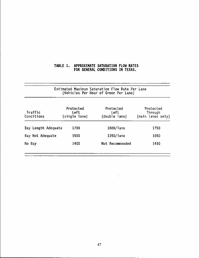
TABLE 1. APPROXIMATE SATURATION FLOW RATES FOR GENERAL CONDITIONS IN TEXAS.
Estimated Maximum Saturation Flow Rate Per Lane (Vehicles Per Hour of Green Per Lane)
Protected Protected Protected Traffic Left Left Through
Condit ions (single lane) (double lane) (main lanes only)
Bay Length Adequate 1700 1600/lane 1750
Bay Not Adequate 1500 1350/lane 1650
No Bay 1400 Not Recommended 1450
47
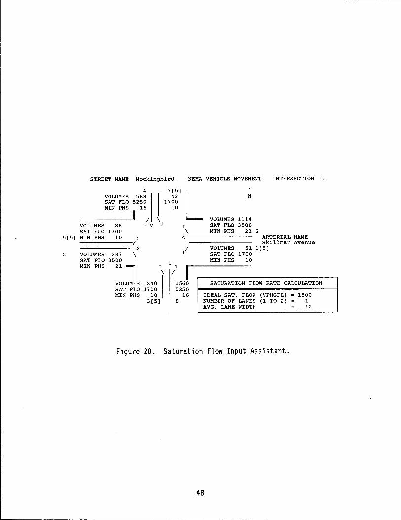
5[5]
2
STREET NAME Mockingbird NEMA VEHICLE MOVEMENT INTERSECTION 1
4 VOLUMES 568 SAT FLO 5250 MIN PHS 16
/ \
7[5] 43
1700 10 L
N
VOLUMES 1114 VOLUMES SAT FLO MIN PHS
VOLUMES SAT FLO MIN PHS
88 1700
10 1 /
> 287 \ 3500
21
l VOLUMES SAT FLO MIN PHS
v r \
<
/ r 1 \ /
240 1700
10 3[5]
1560 5250
16 8
SAT FLO 3500 MIN PHS 21 6
ARTERIAL NAME Skillman Avenue
VOLUMES 51 1[5] SAT FLO 1700 MIN PHS 10
SATURATION FLOW RATE CALCULATION
IDEAL SAT. FLOW (VPHGPL) 1800 NUMBER OF LANES (1 TO 2) 1 AVG. LANE WIDTH 12
Figure 20. Saturation Flow Input Assistant.
48
L.... _________________________________________ ~ __ ~_~ __ _
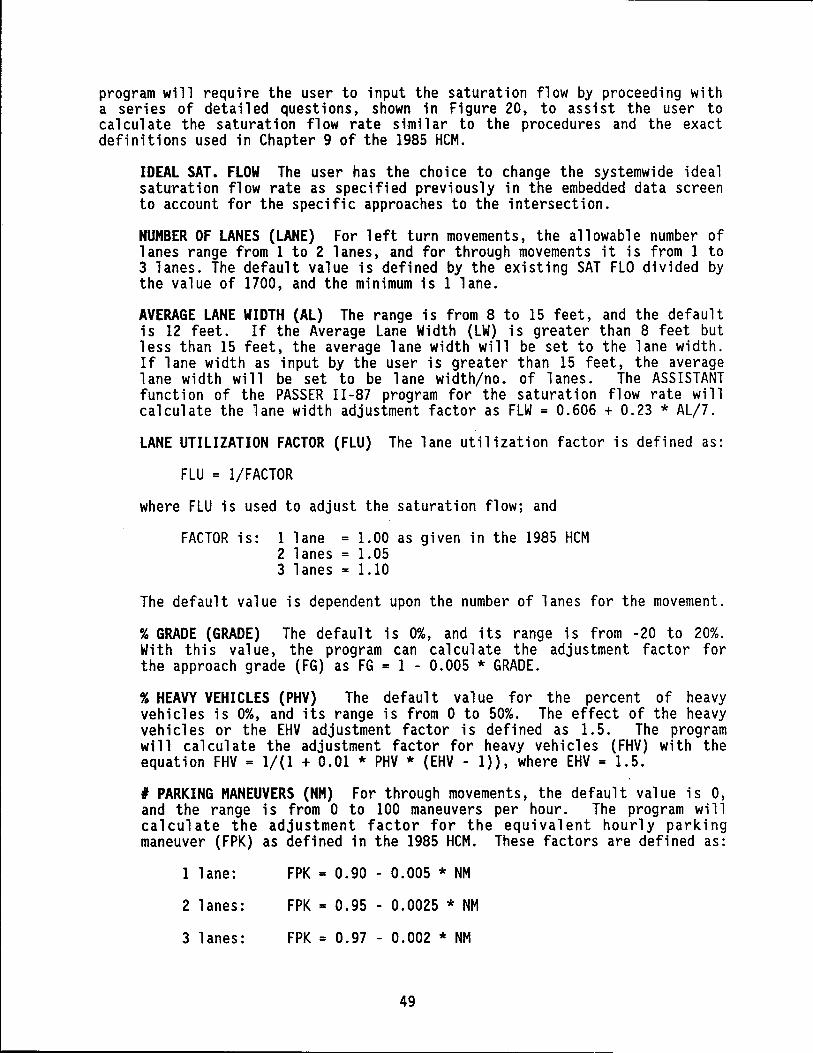
program will require the user to input the saturation flow by proceeding with a seri es of detailed quest ions, shown in Fi gure 20, to ass i st the user to ca 1 cul ate the saturation flow rate s i mil ar to the procedures and the exact definitions used in Chapter 9 of the 1985 HCM.
IDEAL SAT. FLOW The user has the choice to change the systemwide ideal saturation flow rate as specified previously in the embedded data screen to account for the specific approaches to the intersection.
NUMBER OF LANES (LANE) For left turn movements, the allowable number of lanes range from 1 to 2 lanes, and for through movements it is from 1 to 3 lanes. The default value is defined by the existing SAT FLO divided by the value of 1700, and the minimum is 1 lane.
AVERAGE LANE WIDTH (AL) The range is from 8 to 15 feet, and the default is 12 feet. If the Average Lane Width (LW) is greater than 8 feet but less than 15 feet, the average lane width will be set to the lane width. If lane width as input by the user is greater than 15 feet, the average lane width will be set to be lane width/no. of lanes. The ASSISTANT funct i on of the PASSER II -87 program for the saturation flow rate will calculate the lane width adjustment factor as FLW = 0.606 + 0.23 * AL/?
LANE UTILIZATION FACTOR (FLU) The lane utilization factor is defined as:
FLU = I/FACTOR
where FLU is used to adjust the saturation flow; and
FACTOR is: 1 lane = 1.00 as given in the 1985 HCM 2 1 anes = 1. 05 3 lanes = 1.10
The default value is dependent upon the number of lanes for the movement.
% GRADE (GRADE) The default is 0%, and its range is from -20 to 20%. With this value, the program can calculate the adjustment factor for the approach grade (FG) as FG = 1 - 0.005 * GRADE.
% HEAVY VEHICLES (PHV) The default value for the percent of heavy vehicles is 0%, and its range is from 0 to 50%. The effect of the heavy veh i c 1 es or the EHV adj ustment factor is defi ned as 1. 5. The program will calculate the adjustment factor for heavy vehicles (FHV) with the equation FHV = 1/(1 + 0.01 * PHV * (EHV - I)}, where EHV = 1.5.
I PARKING MANEUVERS (NM) For through movements, the default value is 0, and the range is from 0 to 100 maneuvers per hour. The program will calculate the adjustment factor for the equivalent hourly parking maneuver (FPK) as defined in the 1985 HCM. These factors are defined as:
1 1 ane:
2 lanes:
3 lanes:
FPK = 0.90 - 0.005 * NM
FPK = 0.95 - 0.0025 * NM
FPK = 0.97 - 0.002 * NM
49
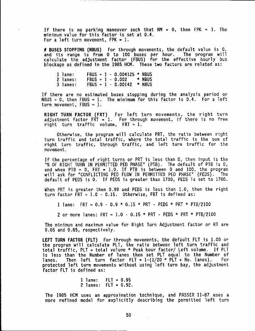
- ~- ~----~-~~----.------------------------------------
If there is no parking maneuver such that NM = 0, then FPK = 1. The minimum value for this factor is set at 0.4. For a left turn movement, FPK = 1.
I BUSES STOPPING (NBUS) For through movements, the default value is 0, and its range is from a to 100 buses per hour. The program will calculate the adjustment factor (FBUS) for the effective hourly bus blockage as defined in the 1985 HCM. These two factors are related as:
1 1 ane: 2 lanes: 3 lanes:
FBUS = 1 - 0.004125 * NBUS FBUS = 1 - 0.002 * NBUS FBUS = 1 - 0.00142 * NBUS
If there are no estimated buses stopping during the analysis period or NBUS = 0, then FBUS = 1. The minimum for this factor is 0.4. For a left turn movement, FBUS = 1.
For left turn movements, the right turn For through movement, if there is no free
FRT = 1.
RIGHT TURN FACTOR (FRT) adjustment factor FRT = 1. right turn traffic volume,
Otherwi se, the program will cal cul ate PRT, the ratio between ri ght turn traffi c and total traffi c, where the total traffi cis the sum of right turn traffic, through traffic, and left turn traffic for the movement.
If the percentage of right turns or PRT is less than 0, then input is the "I OF RIGHT TURN IN PERMITTED PED PHASE" (PTB). The default of PTB is 0, and when PTB = 0, FRT = 1. O. If PTB is between a and 100, the program will ask for "CONFLICTING PED FLOW IN PERMITTED PED PHASE" (PEDS). The default of PEDS is O. If PEDS is greater than 1700, PEDS is set to 1700.
When PRT is greater then 0.99 and PEDS is less than 1.0, then the right turn factor FRT = 1. a - 0.15. Otherwi se, FRT is defi ned as:
1 lane: FRT = 0.9 - 0.9 * 0.15 * PRT - PEDS * PRT * PTB/2IOO
2 or more lanes: FRT = 1.0 - 0.15 * PRT - PEDS * PRT * PTB/2IOO
The minimum and maximum value for Right Turn Adjustment factor or RT are 0.05 and 0.85, respectively.
LEFT TURN FACTOR (FLT) For through movements, the default FLT is 1.00 or the program will cal cul ate PL T, the ratio between 1 eft turn traffi c and total traffic, PLT = total volume * Peak hour factor/ Left volume. If PLT is 1 ess than the Number of 1 anes then set PL T equal to the Number of 1 anes. Then 1 eft turn factor FL T = 1- (1/20 * PL T + No. 1 anes) . For protected left turn movements without using left turn bay, the adjustment factor FLT is defined as:
1 lane: FLT = 0.95 2 lanes: FLT = 0.92.
The 1985 HCM uses an approximation technique, and PASSER II-87 uses a more refined model for explicitly describing the permitted left turn
50
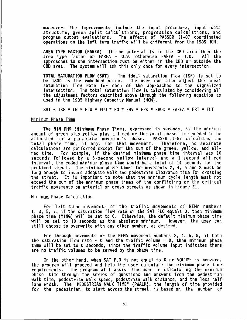
maneuver. The improvements include the input procedure, input data structure, green split calculations, progression calculations, and program output eva 1 uat ions. The effects of PASSER II -87 coordi nated operations on the left turn traffic will be different from the 1985 HCM.
AREA TYPE FACTOR (FAREA) If the arteri a1 is in the CBD area then the area type factor or FAREA = 0.9, otherwi se FAREA = 1. 0 . All the approaches to one intersection must be either in the CBD or outside the CBD area. The system will ask this only once for every intersection.
TOTAL SATURATION FLOW (SAT) The ideal saturation flow (ISF) is set to be 1800 as the embedded val ue. The user can also adjust the ideal saturation flow rate for each of the approaches to the signalized intersection. The total saturation flow is calculated by considering all the adjustment factors described above through the following equation as used in the 1985 Highway Capacity Manual (HCM).
SAT = ISF * LN * FLW * FLU * FG * FHV * FPK * FBUS * FAREA * FRT * FLT
Minimum Phase Time
The MIN PHS (Minimum Phase Time), expressed in seconds, is the mlnlmUm amount of green plus yellow plus all-red or the total phase time needed to be allocated for a part i cu1 ar movement I s phase. PASSER II -87 cal cul ates the total phase time, if any, for that movement. Therefore, no separate calculations are performed except for the sum of the green, yellow, and allred time. For example, if the desired minimum phase time interval was 10 seconds followed by a 3-second yellow interval and a I-second all-red interval, the coded minimum phase time would be a total of 14 seconds for the pretimed signal. The minimum phase times for movements 2, 4, 6 and 8 must be long enough to insure adequate walk and pedestrian clearance time for crossing the street. It is important to note that the minimum cycle length must not exceed the sum of the minimum phase times of the conflicting or the critical traffic movements on arterial or cross streets as shown in Figure 21.
Minimum Phase Calculation
For left turn movements or the traffic movements of NEMA numbers 1, 3, 5, 7, if the saturation flow rate or the SAT FLO equals 0, then minimum phase time (MING) will be set to O. Otherwise, the default minimum phase time will be set to 10 seconds as the absolute minimum. However, the user can still choose to overwrite with any other number, as desired.
For through movements or the NEMA movement numbers 2, 4, 6, 8, if both the saturation flow rate = 0 and the traffic volume = 0, then minimum phase time will be set to 0 seconds, since the traffic volume input indicates there are no traffic volumes to be served by the phase time.
On the other hand, when SAT FLO is not equal to 0 or VOLUME is nonzero, the program will proceed and help the user calculate the minimum phase time requirements. The program will assist the user in calculating the minimum phase time through the seri es of questions and answers from the pedestri an walk time, pedestrian walk speed, pedestrian walk distance, and the less half lane width. The "PEDESTRIAN WALK TIME" (PWALK), the length of time provided for the pedestrian to start across the street, is based on the number of
51
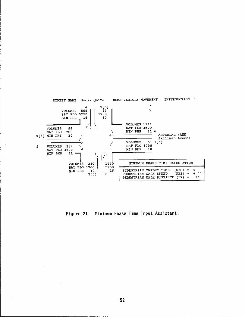
STREET NAME Mockingbird NEMA VEHICLE MOVEMENT INTERSECTION 1
4 7[5] VOLUMES 568 43
L N
SAT FLO 5250 1700 MIN PHS 16 10
/ \ VOLUMES 1114 VOLUMES 88 v r SAT FLO 3500 SAT FLO 1700 \ MIN PHS 21 6
5[5] MIN PHS 10 1 < ARTERIAL NAME
/ Skillman Avenue > / VOLUMES 51 1[5]
2 VOLUMES 287 \ SAT FLO 1700 SAT FLO 3500 MIN PHS 10 MIN PHS
21l r 1 \ /
VOLUMES 240 1560 MINIMUM PHASE TIME CALCULATION ~AT FLO 1700 5250 ~IN PHS 10 16 PEDESTRIAN "WALK" TIME (SEC) 4
3[5] 8 PEDESTRIAN WALK SPEED (FPS) 4.00 PEDESTRIAN WALK DISTANCE (FT) 75
Figure 21. Minimum Phase Time Input Assistant.
52
pedestrians counted during the traffic volume count. If there is a sufficiently high volume of pedestrians to justify the use of pedestrian "Walk" and "Don't Walk" signals, the "Walk" period should be 7 seconds or more in length. On the other hand, if the pedestrian volume is relatively high but not high enough to justify the installation of "Walk" and "Don't Walk" signals, a minimum of 5 seconds is used for this initial interval. And last, if there is only an occasional pedestrian, a minimum of 3 seconds may be used for the initial interval. The default pedestrian walk time is 4 seconds.
Next, the program will ask the user to input "PEDESTRIAN WALK SPEED" (PSPEED). The default value for the pedestrian walk speed is 4 feet per second, and its range is from 3 to 5 feet per second. Then, the user will be asked to input "PEDESTRIAN WALK DISTANCE" (POIST) and "LESS HALF LANE WIDTH" (HLW). The default value for POIST is 0 feet, and the default value for HLW is 6 feet or half of a typical lane width.
The minimum through movement phase time (MING) equation is MING = «PDIST - HLW)/PSPEED) + PWALK. The ASSISTANT will not recommend a value for minimum phase time or for a through movement of less than is 15 seconds. The values of the ASSISTANT function should only serve as recommended values.
The user may use this function to assist in the calculation of the traffic volume, saturation flow rate, and the minimum phase time. The use of the ASSISTANT function is not mandatory but it is recommended to provide online assistance for the engineering calculations. However, it is recommended that the use of the ASSISTANT function be consistent at least for the same intersection or the paired left and through traffic coming from the same approach to the intersection. The program will only recommend one possible value to be used. In the end, the user still needs to decide whether to use the recommended values or overwrite it with any other numbers.
SAVING AND LOADING DATA SETS
Both saving and loading data sets can be accomplished by selecting proper actions in the main menu. To save a data set, the user selects item 4 and is prompted for the default path name and fil e name. Si nce there exi sts only 1 i mi ted room on the A dri ve for program storage, all the input data sets should be stored on the B drive for the two disk drive operation. On the other hand, selecting number 2 on the main menu will allow the user to read an existing data set; the program will check if the existing data loaded has been changed or not. If it does, the program will ask the user if he wishes to abandon the old data. If the old data is kept, the program will not load in the new data set, the system will return to the main menu. It is preferable to load only data sets which were created by this system. However, PASSER 11-87 can also load the existing PASSER 11-84 data sets and mainframe data sets and insert the needed information when the data is saved.
RUNNING PASSER 11-87
After all data elements have been successfully entered, the system di rects the user to save the data before any other data can be loaded or before the program can be executed. Once PASSER I I -87 has been run, the output prepared for that run will be automatically reloaded into the system to be reviewed in the output menu. The only time the user needs to save a data set is when the user wants to run that problem later or load another data set
53
for further editing. The system remembers the last path name and file name used while saving or loading a data set. If no additional input is being made, it displays on the screen the last filename being used and automatically loads the data set when the system is restarted. The user may change the data fi 1 e to be used if des ired. When the user wants to exi t the system, the system will require the user to save the data file if no file save operation has been performed since the last modifications. Therefore, the contents and the filename will not be forgotten. The input menu allows the user to load files from other disks in order to modify or execute them in PASSER 11-87.
After the user chooses to run PASSER 11-87, the system checks for user data input errors to avoid any possible program run-time errors. First, left turn treatment and signal phase patterns are selected for volume input and inappropriate patterns will be deleted. Secondly, minimum phase times will automatically be set equal for those simultaneous movements in the phase sequences without overlap options. The larger green of the two phase movement will be used if unequal greens are specified. The sum of the critical phase minimum greens will also be checked to ensure that the sum will always be less than the lower cycle length as specified by the user. After the user chooses 6 on the main menu to run the program, the system wi 11 check the data for possible major data input errors which may cause PASSER 11-87 to malfunction. This check insures that:
1. The phase patterns selected correspond to the movement volumes. If the user input is not allowed according to the logical phase table, inappropriate patterns will be deleted from the user's input data.
2. The minimum phase times are set equal to those simultaneous movements in phase patterns without overlap. The larger green will be used if unequal greens were specified.
3. The sum of both the arterial and cross street critical phase minimum greens is less than the amount of the lower cycle length which is considered a FATAL ERROR.
4. Each arterial and cross street must be selected with at least one phase pattern selected. Otherwise, a FATAL ERROR may occur.
Errors 3 and 4 are fatal and will stop the user from running the PASSER 11-87 main program. Otherwise, the system will load the PASSER II program and run it. The run time version of PASSER 11-87 is very efficient without requ i ri ng the use of the 8087/80287/80387 math coprocessor. After PASSER II has been run, the program wi 11 then return to the output postprocessor of the PASSER 11-87 microcomputer system, and the output menu will be displayed again. The output menu is explained in the next section.
OUTPUT MENU
After the user runs PASSER II -87, the system will return to the output menu for the user to review the optimized Signal timing plan. Therefore,it is recommended that PASSER 11-87 always be run after changes have been made in the data set so that the current output can always be matched with the input data fi 1 e. After the program is executed, the system wi 11 return to the output menu as shown in Figure 22. If the user selects the output menu from the input menu before PASSER I I -87 is run, the output may be the fi 1 e 1 eft from the last time the program was run and may not correspond to the data that was entered. Therefore, the program shoul d always be run after changes have been made in the data so that the output will match the input data.
54
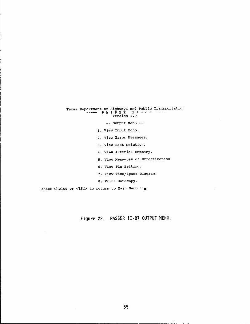
Texas Department of Highways and Public Transportation PAS S E R I I - 8 7
Version 1.0
output Menu
1- View Input Echo.
2. View Error Messages.
3. View Best Solution.
4. View Arterial Summary.
5. View Measures of Effectiveness.
6. View Pin setting.
7. View Time/space Diagram.
8. Print Hardcopy.
Enter choice or <ESC> to return to Main Menu :1.
Figure 22. PASSER 11-87 OUTPUT MENU.
55
An example printout from PASSER 11-87 is provided at the end of this manual. PASSER 11-87 provides an exceptional list of output features. For example, the user can specify the output level to be processed in the input menu and review or print specific portions of the program results from the output menu. The typi ca 1 output is headed by the echo pri ntout of arteri a 1 parameters (COVER), listing of system embedded data (EMBED. DATA) , intersection input (INPUT.DATA), and error report (ERROR.MSG). The optimized program solution output provides a listing of the optimal timing evaluation for the arterial street (ART.SUMY), optimal signal timing plans for each intersection (INT.SUMY), a series of level of service evaluations for each phase movement (BEST.SOLN), total arterial system performance (ART.MOE), two controll er phase interval setting report (PIN. SET), and optimal time-space diagram (TS.DIAGM) if requested. The implementation of the optimal timing plans in the open-type signal network can be greatly facilitated by using the controller phase interval tables to genterate coordinated offsets with respect to the system master intersection for mi croprocessor-based traffi c actuated signal equipment. The available output menu choices are:
1. View Input Echo.
Allows the user to view, page by page, an echo printout of the input data whi ch is generated by PASSER II -87 . Thi sport i on of the program output includes the echo printout of arterial parameters (COVER), listing of system embedded data (EMBED.DATA) , and intersection input (INPUT.DATA).
2. View Error Messages.
Allows the user to review the input data error report (ERROR.MSG).
3. View Best Solution.
Allows the user to vi ew the signal t i mi ng reports, intersect i on by intersection, and the best progression solution generated. This reports a series of level of service evaluations for each phase movement (BEST.SOLN).
4. View Arterial Summary.
The optimized program solution output provides a listing of the optimal timing evaluation for the arterial street (ART.SUMY) and optimal signal timing plans for each intersection (INT.SUMY). This output is not available when only one intersection is analyzed.
5. View Measures of Effectiveness.
Allows the user to review the program displaying the system-wide measures of effectiveness, including the bandwidth efficiency and the optimized cycle in total arterial system performance (ART.MOE).
6. View Pin Setting.
Allows the user to examine the two sets of controller phase interval setting reports generated to translate the optimized signal timing results to user-specified parameters in the controller phase
56
interval setting report (PIN.SET). The controller phase interval tables can greatly facilitate timing implementation in the open-type network.
7. View Time/Space Diagram.
Allows the user to examine the optimized timing plan graphically corresponding to the best progression solution for the arterial street under analysis, if the report (TS.DIAGM) is requested. Since there are only 80 columns of 24 lines available on each screen d i sp 1 ay, two act ions were made in PASSER II -87 . The progress i on bands were pushed and scales were adjusted so that the time-space diagram could provide the maximum viewing and the bands could start at the origin. Arterial and intersection names are illustrated as they are coded. Time reads from left to right on the horizontal axis. The distance scale reads from bottom to top with the accumulation distance measured on the left-hand side of the diagram. The progression bands are described by the different printer characters. In the PASSER 11-87 time-space diagram, a blank or " "indicates the red or the cross street phase; "===" is DUAL LEFTS (I+5), "XXX" is DUAL THRUS (2+6), "///" is LT 5 LEADS (2+5), "\\\" is LT 1 LEADS (1+6). The "A" Direction Progression Band goes up and to the right; the "B" Direction Progression Band comes down and to the right. The default coordinated progression offsets, expressed either in seconds or the % of cycle length, are with respect to the start of the arterial phases at intersection 1. Note that both the 1 eft and the through movement phases are expressed separately in the time-space diagram.
8. Print All Output.
All portions of PASSER 11-87 output, as shown in Figure 23, will be sent to the printer. The PASSER 11-87 program output will be produced in the form of 66 lines per page with 80 columns per line; no spec i a 1 pri nter is requ i red for the program pri ntout. The user can select portions of the program output by selectively turning off the part i cul ar port i on of the output not wanted by toggl i ng the RETURN key.
The user can also press the ESC key at any time to return to the main menu to compare the results of the PASSER 11-87 to the input data. The user may then return to the output menu by selecting the appropriate choice on the main menu. Data may be edited at will, but the changes in the input data will not be visible in the output until the PASSER 11-87 program is run again.
EXITING THE INPUT PREPROCESSOR AND OUTPUT POSTPROCESSOR
When all the input data have been entered and approved, the input preprocessor and output postprocessor will automatically save the data in a data file on the designated data diskette, for example, in the default drive B, or the alternative hard drive. The user can save the current data set into the file in order to use the data file later, and then exit the PASSER 11-87 system by selecting number 8 from the main menu.
57
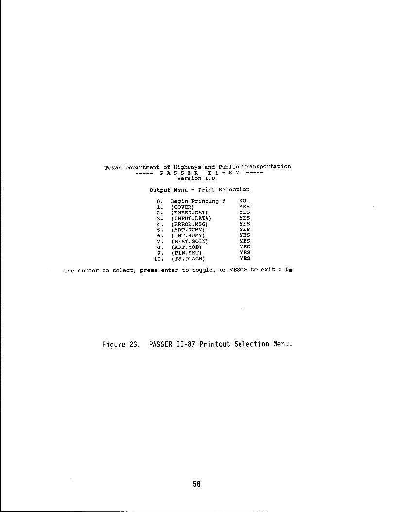
Texas Department of Highways and Public Transportation PAS S E R I I - 8 7
Version 1.0
output Menu - Print Selection
O. Begin Printing ? NO 1. (COVER) YES 2. (EMBED.DAT) YES 3. (INPUT. DATA) YES 4. (ERROR.MSG) YES 5. (ART.SUMY) YES 6. (INT.SUMY) YES 7. (BEST.SOLN) YES 8. (ART. MOE) YES 9. (PIN.SET) YES
10. (TS.DIAGM) YES
Use cursor to select, press enter to toggle, or <ESC> to exit o.
Figure 23. PASSER 11-87 Printout Selection Menu.
58
ADDITIONAL CONSIDERATIONS
Several of the most important topics concerning the use of the PASSER 11-87 program are discussed in the following section. These topics include left turn signal treatments, phase pattern selection, basic keyboard commands, optimization of arterial signal systems with up to 20 intersections, a summary of the operating procedures, and operational efficiency.
LEFT TURN SIGNAL TREATMENTS
In order to assist users in analyzing and evaluating the operational effects of different left turn traffic signal treatments under coordinated progression operations, PASSER 11-87 has been significantly enhanced with advanced methods beyond the 1985 HCM technology. These PASSER II -87 improvements include the enhancements made in the input procedure, input data structure, green split calculations, progression calculations, and output performance evaluations. In addition, compared with the approximation techniques used in the 1985 HCM, PASSER 11-87 uses a much more refined model for explicitly describing the left turn maneuvers and resulting capacity.
The PASSER 11-87 program uses a minimum amount of information to generate left turn treatments as well as to examine allowable signal phase sequences according to user traffic data. The input data was designed to simplify the user's input and still be able to provide the necessary user assistance for analyzing the various left turn signal treatments and capacity evaluations. These treatments include those with simple two-phase "Permitted Phase" and sophisticated "Protected Phase" operations as well as those with the most compl icated permitted/protected or protected/permitted "Combined Phase" left turn sequences. However, PASSER I I -87 wi 11 st ill assume the use of the default "Protected" phase operation, as used in the existing PASSER II-84 program, if a left turn bay is used. On the other hand, the new program will assume the use of the default "Permitted" phase when no left turn bay exists or if the user does not specify a particular left turn signal treatment being used in the analysis.
Left Turn Treatment Data Input Method
The PASSER II-87 left turn data input was basically designed to accept all available user information through the on-line help display screen to generate all the necessary data as well as provide user with instructions for solution analysis. User input will be examined and evaluated to generate the possible left turn treatments and to investigate the allowable signal phase sequence. However, the proper analysis of the different left turn signal operations requires that a large amount of information about left turn signal treatments be provided in the data "ASSISTANT" window for each approach to the signalized intersection. The PASSER 11-87 system was designed to utilize all input information in order to provide 1985 "Highway Capacity Manual" type analysis with the most flexible and simplified input data file structure for all possible left turn signal treatments. In addition, the system preserves the straightforward input data editing and modification functions now available in the existing PASSER 11-84 program, if the user wishes to do so.
59
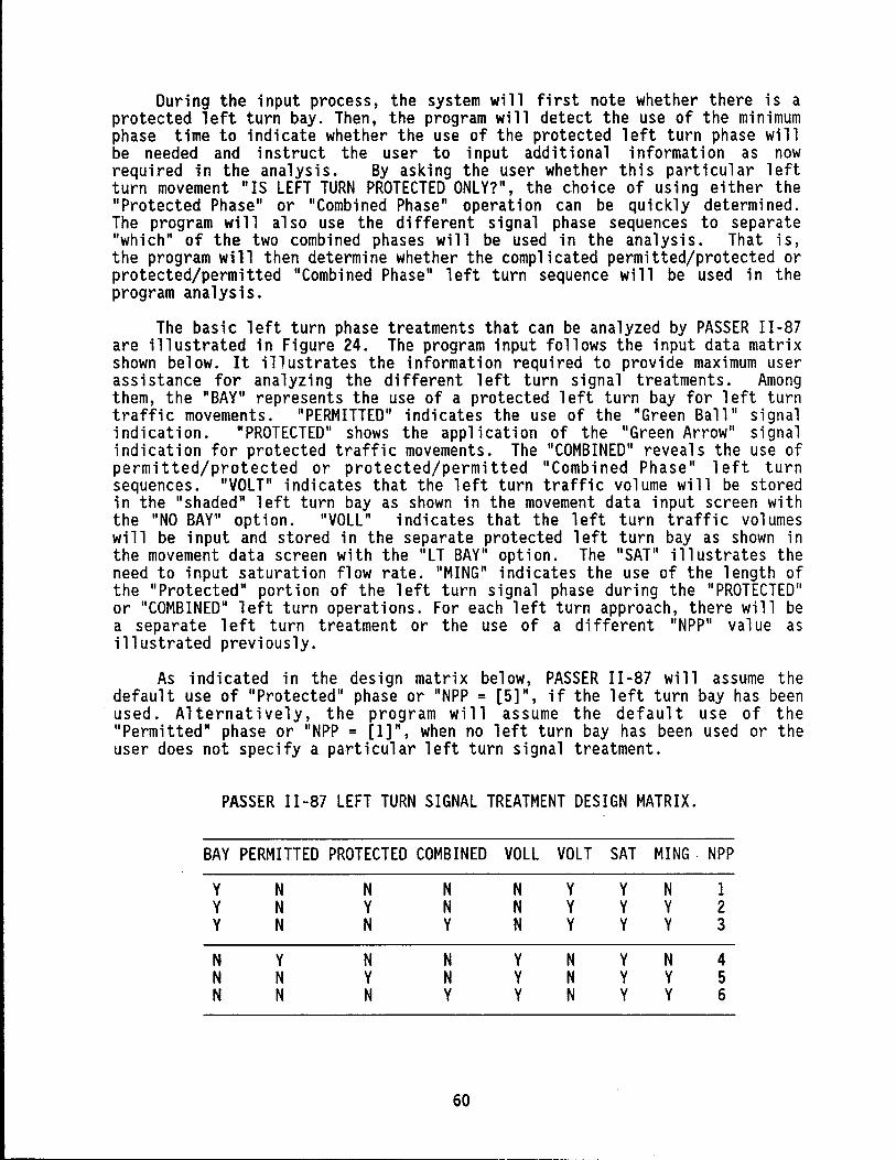
During the input process, the system will first note whether there is a protected left turn bay. Then, the program will detect the use of the minimum phase time to indicate whether the use of the protected left turn phase will be needed and instruct the user to input additional information as now required in the analysis. By asking the user whether this particular left turn movement "IS lEFT TURN PROTECTED ONLY?", the choice of using either the "Protected Phase" or "Combined Phase" operation can be quickly determined. The program will also use the different signal phase sequences to separate "which" of the two combined phases will be used in the analysis. That is, the program will then determine whether the complicated permitted/protected or protected/permitted "Combined Phase" left turn sequence will be used in the program analysis.
The basic left turn phase treatments that can be analyzed by PASSER 11-87 are illustrated in Figure 24. The program input follows the input data matrix shown below. It illustrates the information required to provide maximum user assistance for analyzing the different left turn signal treatments. Among them, the "BAY" represents the use of a protected left turn bay for left turn traffic movements. "PERMITTED" indicates the use of the "Green Ball" signal indication. "PROTECTED" shows the application of the "Green Arrow" signal indication for protected traffic movements. The "COMBINED" reveals the use of permitted/protected or protected/permi tted "Combi ned Phase" 1 eft turn sequences. "VOLT" indicates that the left turn traffic volume will be stored in the "shaded" left turn bay as shown in the movement data input screen with the "NO BAY" option. "VOll" indicates that the left turn traffic volumes will be input and stored in the separate protected left turn bay as shown in the movement data screen with the ''IT BAY" option. The "SAT" illustrates the need to input saturation flow rate. "MING" indicates the use of the length of the "Protected" portion of the left turn signal phase during the "PROTECTED" or "COMBINED" left turn operations. For each left turn approach, there will be a separate left turn treatment or the use of a different "NPP" value as illustrated previously.
As indicated in the design matrix below, PASSER II-87 will assume the default use of "Protected" phase or "NPP = [5]", if the left turn bay has been used. A 1 ternat i vel y, the program will as sume the defaul t use of the "Permitted" phase or "NPP = [1]", when no left turn bay has been used or the user does not specify a particular left turn signal treatment.
PASSER 11-87 lEFT TURN SIGNAL TREATMENT DESIGN MATRIX.
BAY PERMITTED PROTECTED COMBINED VOll VOLT SAT MING ' NPP
Y N N N N Y Y N 1 Y N Y N N Y Y Y 2 Y N N Y N Y Y Y 3
N Y N N Y N Y N 4 N N Y N Y N Y Y 5 N N N Y Y N Y Y 6
60
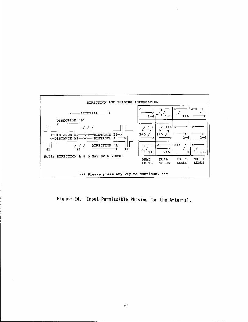
DIRECTION AND PHASING INFORMATION
<--ARTERIAL-->
DIRECTION 'B' <
J kISTANCE B2 / >~ / DISTANCE ;d \ L <-DISTANCE A2-><-DISTANCE A3->\
l I -/ / / DIRECTION ~ r #1 #2 > #3
NOTE: DIRECTION A & B MAY BE REVERSED
<-- 1--->...J /
2+6 L 1+5
<--/
L 1+6
<-/ 1+6
L 1 2+5 / -->
1 -/ /
- L 1+5
<--/ 1+6 <-
L 1 2+5 / --> --> 2+6
<-- 2+5 1 --> /
2+6 -->
2+5 1 /
-->
<--
--> 2+6
<--/
L 1+6
DUAL LEFTS
DUAL THRUS
NO. 5 NO. 1 LEADS LEADS
*** Please press any key to continue. ***
Figure 24. Input Permissible Phasing for the Arterial.
61
Six of the left turn signal phase treatments can be easily analyzed in PASSER II-87. As shown in Figure 21, a unique "NPP" number or "Left Turn Signal Treatment" will be assigned in the "[ ]" to designate the particular left turn treatments being used. These exact "NPP" values will also be displayed in the Input Data Echo, and a new line is provided in the Best Solution section which gives the Phase Direction. As in PASSER 11-84, PASSER II -87 will the default "Protected phase" or "NPP=[5] II if a 1 eft turn bay is used. Otherwise, the program will assume the default "Permitted phase" or II NPP= [1] II when no 1 eft turn bay is used or the user does not spec ify a particular left turn signal treatment. The "NPP" value represents the left turn signal treatment input by the user. It is explained in the input data ASSISTANT window as follows:
A. WITHOUT LEFT TURN BAY
1. NPP = [1] PERMITTED PHASE OPERATION
NO BAY, "PERMITTED PHASE" OPERATION NEED: VOLUMES, SATURATION FLOW
2. NPP = [2] PROTECTED PHASE OPERATION
NO BAY, "PROTECTED PHASE" OPERATION NEED: VOLUMES, SATURATION FLOW, MINIMUM GREEN TIME
3. NPP = [3] COMBINED PHASE OPERATION
NO BAY, "COMBINED PHASE" OPERATION NEED: VOLUMES, SATURATION FLOW, MINIMUM GREEN TIME
B. WITH LEFT TURN BAY
1. NPP = [4] PERMITTED PHASE OPERATION
l T BAY, "PERMITTED PHASE" OPERATION NEED: VOLUMES, SATURATION FLOW
2. NPP = [5] PROTECTED PHASE OPERATION
IT BAY, "PROTECTED PHASE" OPERATION. NEED: VOLUMES, SATURATION FLOW, MINIMUM GREEN TIME
3. NPP = [6] COMBINED PHASE OPERATION
IT BAY, "COMBINED PHASE" OPERATION NEED: VOLUMES, SATURATION FLOW, MINIMUM GREEN TIME
It is extremely important for the user to understand that some information about left turn signal treatments can not be automatically provided. The user must interact with the program through the ASSISTANT function to instruct the program what to do in order to choose the proper left turn signal treatments as well as perform the necessary saturation flow calculations. The consistent use of the program ASSISTANT function will only be required when different left turn signal treatments and the 1985 HCM type
62
capacity analysis are needed. The existing PASSER II-84 users can still use the interactive input to perform the regular program input if desired. However, the use of the ASSISTANT function as well as checking the proper "NPP" values in the "[ ]" is highly recommended. The system requires much information in order to perform the 1985 HCM type capacity analysis for evaluating the traffic signal timing results. The following instructions are provided expl icitly for the user to apply the necessary traffic data for coding the "PERMITTED," "PROTECTED," and "COMBINED" phase signal treatments in addition to the ASSISTANT function.
FOR CODING THE LEFT TURN BAY
Determi ne the phys i cal presence of a protected 1 eft turn bay and then identify this case by toggling the FUNCTION KEY 2 or F2 KEY.
The following three coding instructions can be displayed on the screen by hitting Fl when the intersection graphics is displayed.
FOR CODING THE "PERMITTED" PHASE
Activate the ASSISTANT function through the FUNCTION KEY 3 or the F3 KEY for left turn TRAFFIC VOLUME input. Answering "YES" to "LEFT TURN PERMITTED GREEN?" selects the permitted phase operation. Then proceed with the traffic volume input, noticing the words "PERMITTED PHASE" in the ASSISTANT window. Check the "NPP" value as either 11[1]" or "[4]" in the "[ ]" for the corresponding left turn traffic movement for the "NO BAY" and "LT BAY" cases.
FOR CODING THE "PROTECTED" PHASE
Activate the ASSISTANT function through FUNCTION KEY 3 or the F3 KEY. Answering "NO" to "LEFT TURN PERMITTED GREEN?" and "YES" to "LEFT TURN PROTECTED GREEN?" selects "PROTECTED PHASE" operation. Then proceed with the volume input, checking "PERMITTED PHASE" in the ASSISTANT window and the "NPP" value as either "[2]" or "[5]" in the "[ ]" for the "NO BAY" and "LT BAY" cases.
FOR CODING THE "COMBINED" PHASE
Activate the ASSISTANT function through FUNCTION KEY 3 or the F3 KEY. Answering "NO" to the question, "LEFT TURN PERMITTED GREEN?" and "NO" to the question "LEFT TURN PROTECTED ONLY?" selects "COMBINED PHASE" operation. Proceed with the traffic volume input by checking the words "COMBINED PHASE" in the ASSISTANT window. The indication of the "NPP" value as either "[3]" or "[6]" for the "NO BAY" and "LT BAY" cases, respectively, should be noticed.
PHASE PATTERN SELECTION
The PASSER II-87 environment system will assist the user in choosing allowable signal phasing pattern(s). The system first finds out which movements have had volumes entered for them and then references these choices to the logical phase sequence tables shown previously in Figure 4. It will then give the user a list of the phasing patterns which the table indicates
63
are applicable. The user can review the signal phase sequences recommended by the program by simply pressing the FUNCTION KEY 3 or F3 KEY. This will indicate the actual signal phase sequence the user has chosen for analysis.
The PASSER 11-87 program uses three logical signal phasing pattern tables, as shown in Figure 4, to help the user determine the different allowable phase sequences according to the traffic volume input by the user. The first two allowable signal phase tables are designed to determine the allowable phase sequences under the normal operation on the arterial and the cross street movements. These two tables should be sufficient for 90% of the PASSER 11-87 analysis requirements. Occasionally, however, the user will need the full range of phasing patterns available. In this case, the user can choose to use the special phasing table. This table will give the user the additional phasing patterns needed to achieve any possible phase sequence for the movements that have nonzero traffic volumes.
For example, assume that there is a signal i zed intersect i on where the left turn movement 5 has a protected phase but the opposing left turn, movement 1, does not have a protected phase. Therefore, movements 2, 5 and 6 have nonzero volumes. Looking at the normal phasing pattern table for arterial phasing, we find only two possible choices of phase patterns. The fi rst, through movements fi rst wi th overl ap or dual throughs wi th overl ap, provides a phase sequence of 2+6, 2+5. The other option, left turn 5 leading with overlap, will give the user the opposite sequence choice: 2+5, 2+6. If, however, a more unusual phase sequence is needed, the user can use the special phase pattern selection and be allowed the phase sequences for four more choi ces as shown below. The phase sequence wi 11 be shown for each of the allowable phase patterns. Please note that if all four movements have nonzero volumes, only one of the two possible overlap phases will be shown for patterns with overlap. The other overlap phase is also available and will be chosen by the PASSER 11-87 system if the traffic volume input w~rrants it.
Phase Pattern Phase Sequence
Left Turns First without Overlap
Through Movements First without Overlap
Left Turn 1 Leading without Overlap
Left Turn 5 Leading without Overlap
64
5, 2+6
2+6, 5
6, 2+5
2+5, 6
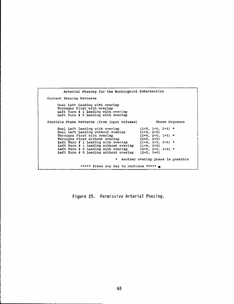
Arterial Phasing for the Mockingbird Intersection
Current Phasing Patterns
Dual Left Leading with overlap Throughs First with overlap Left Turn # 1 Leading with overlap Left Turn # 5 Leading with overlap
Possible Phase Patterns (from input volumes) Phase Sequence
Dual Left Leading with overlap Dual Left Leading without overlap Throughs First with overlap Throughs First without overlap Left Turn # 1 Leading with overlap Left Turn # 1 Leading without overlap Left Turn # 5 Leading with overlap Left Turn # 5 Leading without overlap
(1+5, (1+5, (2+6, (2+6, (1+6, (1+6, (2+5, (2+5,
1+6, 2+6) * 2+6) 2+5, 1+5) * 1+5) 1+5, 2+5) * 2+5) 2+6, 1+6) * 1+6)
* another overlap phase is possible
***** Press any key to continue ***** •
Figure 25. Permissive Arterial Phasing.
65
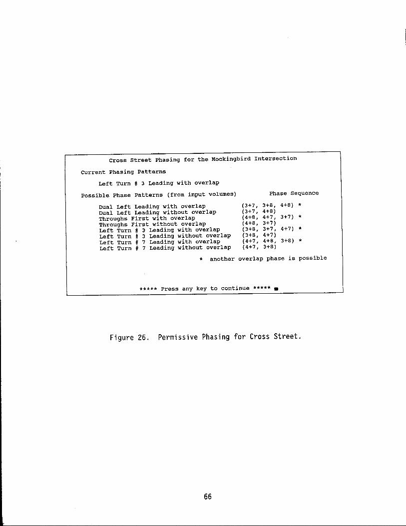
Cross street Phasing for the Mockingbird Intersection
Current Phasing Patterns
Left Turn # 3 Leading with overlap
possible Phase Patterns (from input volumes) Phase Sequence
Dual Left Leading with overlap Dual Left Leading without overlap Throughs First with overlap Throughs First without overlap Left Turn # 3- Leading with overlap Left Turn # 3 Leading without overlap Left Turn # 7 Leading with overlap Left Turn # 7 Leading without overlap
(3+7, (3+7, (4+8, (4+8, (3+8, (3+8, (4+7, (4+7,
3+8, 4+8) * 4+8) 4+7, 3+7) * 3+7) 3+7, 4+7) * 4+7) 4+8, 3+8) * 3+8)
* another overlap phase is possible
***** Press any key to continue ***** •
Figure 26. Permissive Phasing for Cross Street.
66
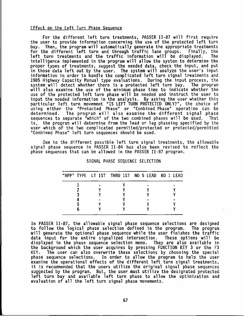
Effect on the Left Turn Phase Sequence
For the different left turn treatments, PASSER 11-87 will first require the user to provide information concerning the use of the protected left turn bay. Then, the program will automatically generate the appropriate treatments for the different left turn and through traffic lane groups. Finally, the left turn treatments and the traffic information will be displayed. The intelligence implemented in the program will allow the system to determine the proper types of treatments, suggest the needed data, check the input, and put in those data left out by the user. The system will analyze the user's input information in order to handle the complicated left turn signal treatments and 1985 Highway Capacity Manual type evaluations. During the input process, the system will detect whether there is a protected left turn bay. The program will also examine the use of the minimum phase time to indicate whether the use of the protected left turn phase will be needed and instruct the user to input the needed information in the analysis. By asking the user whether this part i cul ar 1 eft turn movement "IS LEFT TURN PROTECTED ONLY?", the choi ce of using either the "Protected Phase" or "Combined Phase" operation can be determined. The program will also examine the different signal phase sequences to separate "which" of the two combined phases will be used. That is, the program will determine from the lead or lag phaseing specified by the user which of the two complicated permitted/protected or protected/~ermitted "Combined Phase" left turn sequences should be used.
Due to the different possible left turn signal treatments, the allowable signa 1 phase sequence in PASSER II -84 has also been revi sed to refl ect the phase sequences that can be allowed in the PASSER 11-87 program.
SIGNAL PHASE SEQUENCE SELECTION
"NPP" TYPE LT 1ST THRU 1ST NO 5 LEAD NO 1 LEAD
1 Y 2 Y Y Y Y 3 Y Y Y Y 4 Y 5 Y Y Y Y 6 Y Y Y Y
In PASSER 11-87, the allowable signal phase sequence selections are designed to fo 11 ow the log i cal phase select ion defi ned in the program. The program will generate the optional phase sequence while the user finishes the traffic data input for the entire signalized intersection. These options will be displayed in the phase sequence selection menu. They are also available in the background which the user acquires by pressing FUNCTION KEY 3 or the F3 KEY. The user can also overwrite these selections by choosing the special phase sequence selections. In order to allow the program to help the user examine the operational effects of the different left turn signal treatments, it is recommended that the users utilize the original signal phase sequences suggested by the program. But, the user must utilize the designated protected left turn bay and available left turn phase to allow the optimization and evaluation of all the left turn signal phase movements.
67
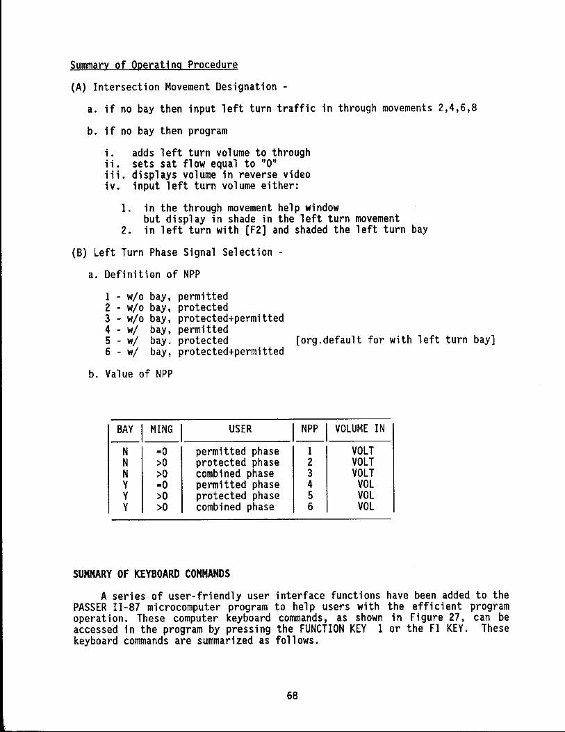
Summary of Operating Procedure
(A) Intersection Movement Designation -
a. if no bay then input left turn traffic in through movements 2,4,6,8
b. if no bay then program
i. adds left turn volume to through ii. sets sat flow equal to "0" iii. displays volume in reverse video iv. input left turn volume either:
1. in the through movement help window but display in shade in the left turn movement
2. in left turn with [F2] and shaded the left turn bay
(8) Left Turn Phase Signal Selection -
a. Definition of NPP
1 - wlo bay, permitted 2 - wlo bay, protected 3 - wlo bay, protected+permitted 4 - wi bay, permitted 5 - wi bay. protected [org.default for with left turn bay] 6 - wi bay, protected+permitted
b. Value of NPP
BAY I MING USER I~I VOLUME IN
N =0 permitted phase 1 VOLT N >0 protected phase 2 VOLT N >0 combined phase 3 VOLT Y =0 permitted phase 4 VOL Y >0 protected phase 5 VOL Y >0 combined phase 6 VOL
SUMMARY OF KEYBOARD COMMANDS
A series of user-friendly user interface functions have been added to the PASSER 11-87 microcomputer program to help users with the efficient program operat ion. These computer keyboard commands, as shown in Fi gure 27, can be accessed in the program by pressing the FUNCTION KEY 1 or the Fl KEY. These keyboard commands are summarized as follows.
68
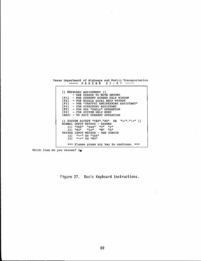
Texas Department of Highways and Public Transportation PAS S E R I I - 8 7
[[ KEYBOARD ASSIGNMENT )) - USE CURSOR TO MOVE AROUND
[F1) [F2) [F3) [F4) [FS) [F6] <ESC>
FOR CURRENT SCREEN HELP WINDOW FOR TOGGLE LOCAL HELP WINDOW FOR "TRAFFIC ENGINEERING ASSISTANT" FOR DIRECTORY ASSISTANT FOR DOS "SHELL" OPERATION FOR SYSTEM HELP MENU TO EXIT CURRENT OPERATION
[ [ SYSTEM ACCEPT "YES","NO" OR n<_",II_>" NORMAL INPUT METHOD - ANSWER
(1) "YES" "yes" "Y" "y" (2) "NO" "no" "N" "n"
KEYPAD INPUT METHOD - USE CURSOR (1) 11<_11 AS "YES" (2) 11_>11 AS "NO"
))
*** Please press any key to continue. *** Which item do you choose? 1.
Figure 27. Basic Keyboard Instructions.
69
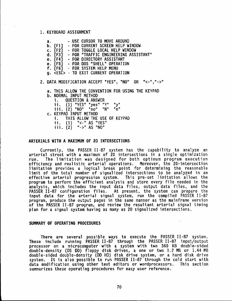
1. KEYBOARD ASSIGNMENT
a. - USE CURSOR TO MOVE AROUND b. [Fl] - FOR CURRENT SCREEN HELP WINDOW c. [F2] - FOR TOGGLE LOCAL HELP WINDOW d. [F3] - FOR "TRAFFIC ENGINEERING ASSISTANT" e. [F4] - FOR DIRECTORY ASSISTANT e. [F5] - FOR DOS "SHELL" OPERATION f. [F6] - FOR SYSTEM HELP MENU g. <ESC> - TO EXIT CURRENT OPERATION
2. DATA MODIFICATION ACCEPT "YES", "NO" OR "<-","->"
a. THIS ALLOW THE CONVENTION FOR USING THE KEYPAD b. NORMAL INPUT METHOD
i. QUESTION & ANSWER ii. (1) "YES" "yes" "Y" "y" iii. (2) "NO" "no" "N" "n"
c. KEYPAD INPUT METHOD i. THIS ALLOW THE USE OF KEYPAD 11. (1) "<_" AS "YES" iii. (2) "->" AS "NO"
ARTERIALS WITH A MAXIMUM OF 20 INTERSECTIONS
Currently, the PASSER 11-87 system has the capability to analyze an arterial street with a maximum of 20 intersections in a single optimization run. The 1 imitation was designed for both optimum program execution efficiency and realistic arterial operations. Moreover, the 20-intersection limitation provides a logical break point for determining the reasonable limit of the total number of signalized intersections to be analyzed in an effective arterial progression system. This pre-set limitation allows the program to perform the efficient analysis and store every file needed in the analysis, which includes the input data files, output data files, and the PASSER I I -87 confi gurat ion fi 1 es. At present, the system can prepare the input data for the arterial signal system, run the compiled PASSER II-87 program, produce the output pages in the same manner as the mainframe version of the PASSER 11-87 program, and review the resultant arterial signal timing plan for a signal system having as many as 20 signalized intersections.
SUMMARY OF OPERATING PROCEDURES
There are several possible ways to execute the PASSER 11-87 system. These include running PASSER 11-87 through the PASSER 11-87 input/output processor on a microcomputer with a system with two 360 KB double-sided double-density (OS DO) floppy disk drives, a one or two 1.2 MB or 1.44 MB double-sided double-density (DO HD) disk drive system, or a hard disk drive system. It is also possible to run PASSER 11-87 through the cold start with data modification using other text editors or wordprocessors. This section summarizes these operating procedures for easy user reference.
70
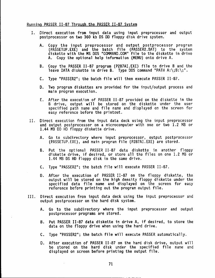
Running PASSER 11-87 Through the PASSER 11-87 System
1. Di rect execution from input data us i ng input preprocessor and output postprocessor on two 360 kb DS DD floppy disk drive system.
A. Copy the input preprocessor and output postprocessor program (PASSETUP.EXE) and the batch file (PASSER2.BAT) to the system diskette with the MS DOS "COMMAND. COM" file to the diskette in drive A. Copy the optional help information (MENU) onto drive A.
B. Copy the PASSER 11-87 program (P287AI.EXE) file to drive B and the leave DATA diskette in drive B. Type DOS command "PATH A:\;B:\;II.
C. Type" PASSER2"; the batch fil e will then execute PASSER II -87 .
D. Two program diskettes are provided for the input/output process and main program execution.
E. After the execution of PASSER 11-87 provided on the diskette in the B dri ve, output wi 11 be stored on the di skette under the user specified path name and file name and displayed on the screen for easy reference before the printout.
II. Direct execution from the input data deck using the input preprocessor and output postprocessor on a microcomputer with one or two 1.2 MB or 1.44 MB DD HD floppy diskette drive.
A. Go to subdirectory where input preprocessor, output postprocessor (PASSETUP.EXE), and main program file (P287AI.EXE) are stored.
B. Put the optional PASSER 11-87 data diskette in another floppy diskette drive, if desired, or store all the files on one 1.2 MB or 1.44 MB DS HD floppy disk in the same drive.
C. Type" PASSER2 11; the batch fil e will execute PASSER II -87 .
D. After the execution of PASSER II -87 on the floppy di skette, the output will be stored on the high density floppy diskette under the specified data file name and displayed on the screen for easy reference before printing out the program output file.
III. Direct execution from input data deck using the input preprocessor and output postprocessor on the hard disk system.
A. Go to the subdirectory where the input preprocessor and output postprocessor programs are stored.
B. Put PASSER 11-87 data diskette in drive A, if desired, to store the data on the floppy drive when using the hard drive.
C. Type "PASSER2"; the batch file will execute PASSER automatically.
D. After execution of PASSER 11-87 on the hard disk drive, output will be stored on the hard disk under the specified file name and displayed on screen before printing the output file.
71
------------------------------------------------
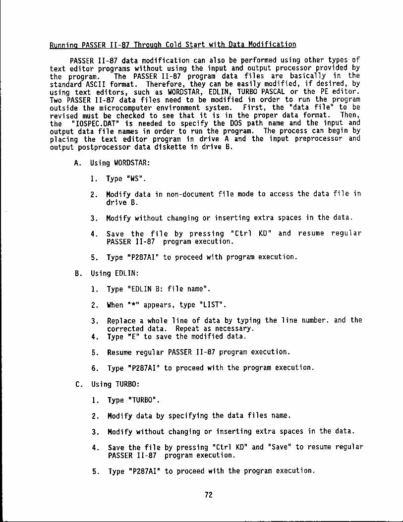
Running PASSER 11-87 Through Cold Start with Data Modification
PASSER 11-87 data modification can also be performed using other types of text editor programs without using the input and output processor provided by the program. The PASSER 11-87 program data files are basically in the standard ASCII format. Therefore, they can be easily modified, if desired, by using text editors, such as WORDSTAR, EDLIN, TURBO PASCAL or the PE editor. Two PASSER 11-87 data files need to be modified in order to run the program outside the microcomputer environment system. First, the "data file" to be revised must be checked to see that it is in the proper data format. Then, the II IOSPEC. DATil is needed to specify the DOS path name and the input and output data file names in order to run the program. The process can begin by placing the text editor program in drive A and the input preprocessor and output postprocessor data diskette in drive B.
A. Using WORDSTAR:
1. Type "WS".
2. Modify data in non-document file mode to access the data file in drive B.
3. Modify without changing or inserting extra spaces in the data.
4. Save the fi 1 e by press i ng "Ctrl KDII and resume regul ar PASSER 11-87 program execution.
5. Type IIp287AI" to proceed with program execution.
B. Using EDLIN:
1. Type IIEDLIN B: file name ll•
2. When "*" appears, type IILIST II .
3. Replace a whole line of data by typing the line number. and the corrected data. Repeat as necessary.
4. Type "E" to save the modified data.
5. Resume regular PASSER 11-87 program execution.
6. Type "P287AI II to proceed with the program execution.
C. Using TURBO:
1. Type "TURBO".
2. Modify data by specifying the data files name.
3. Modify without changing or inserting extra spaces in the data.
4. Save the file by pressing IICtrl KD" and "Save" to resume regular PASSER 11-87 program execution.
5. Type "P287AI" to proceed with the program execution.
72
D. Using PE:
1. Type "PE".
2. Modify data by specifying "Edit" or "E" at the command line.
3. Modify without changing or inserting extra spaces in the data.
4. Save the file by pressing "ESC" and "FILE" to resume regular PASSER 11-87 program execution.
5. Type "P287AI" to proceed with the program execution.
OPERATIONAL EFFICIENCY
To facilitate the speed and efficiency of the PASSER 11-87 program runs, the following actions are highly recommended for IBM PC/XT/AT or compatible microcomputers.
Use Subdirectories
The user may tap the power of DOS's tree-structured directory system to help the user manage the work. Subdirectories may be used to help the user setup the hard disk files just as filing folders do in paper files. It is recommended to create a separate subdi rectory to contain each app 1 i cat ion program and each work problem. The current directory is displayed with the DOS PROMPT $P$G command. Don't c 1 ut ter the root directory - th iss lows the DOS down and makes operation more complicated than necessary. In the root, there should be only the four essential DOS files: COMMAND.COM, ANSI.SYS, AUTOEXEC.BAT, CONFIG.SYS, and subdirectories. Additional subdirectories, as recommended in Figure 28, can be managed through three simple DOS commands, MKDIR, CHDIR, RMDIR, for efficiently creating, switching, and removing subdirectories. It is highly recommended to create the CONFIG.SYS file to use "DEVICE=ANSI.SYS, FILES-20, BUFFERS-40" to speed up program operation.
Use BAT Files and the PATH Commands
After using the subdirectory structure to organize the files stored on the hard dis k, it is also important to reta in the freedom to run other application programs for further data reduction and analysis. For example, it is recommended to create three standard subdirectories: \BAT for batch files, \DOS for the DOS programs, and \UTI L for preferred ut il i ty programs. Pl ace these three subdirectory names in the PATH of the AUTOEXEC.BAT file using the DOS command PATH = C:\BAT;C:\DOS;C:\UTIL; - so the user can run any app 1 i cat i on program in anyone of these subd i rectori es from anywhere on the hard disk. For those programs that are not in one of these standard subdirectories, the user can use small batch files located in C:\BAT to change among the different directories and run the different application programs.
73
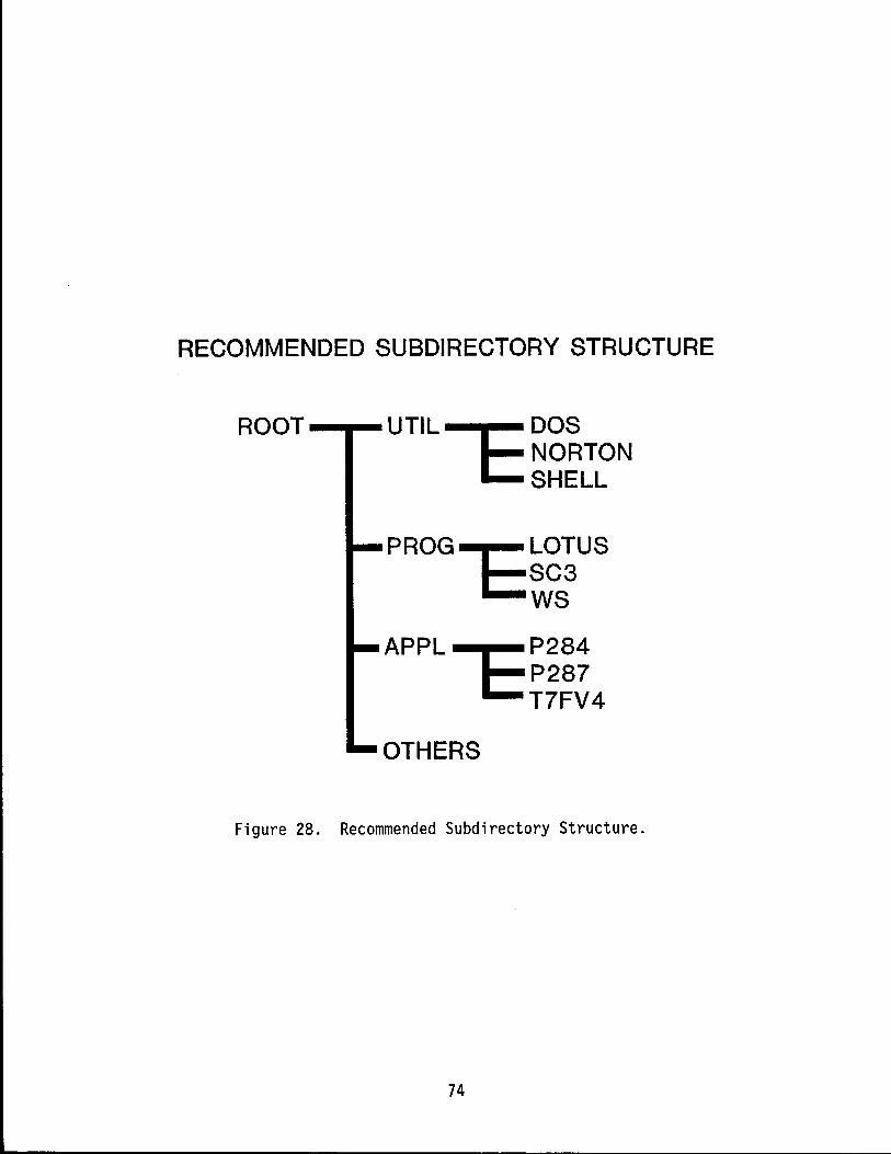
RECOMMENDED SUBDIRECTORY STRUCTURE
ROOT - .... UTIL ~ DOS NORTON SHELL
PROG -r:: LOTUS
E::SC3 WS
APPL -r:: P284
t:: P287 T7FV4
OTHERS
Figure 28. Recommended Subdirectory Structure.
74
Choose a DOS Shell Program
The normal DOS shell program is COMMAND. COM. Some new users often find it intimidating and uninstructive. Other experts wish it had abilities like file tagging, unerasing, and directory renaming. Many commercial software deve 1 opers, such as the computer software package developed by Peter Norton and others have developed different Utilities programs, such as XTREE, QDOS, NORTON UTILITY, WordPerfect SHELL, and other commercially available computer ut i 1 i ty programs. These programs can be very powerful in prepari ng the application program menu system and organizing the Disk Operating System (DOS). Many utility programs have gone through several improvements to incorporate many powerful new features, such as the fri endl y command "integrator" with menus and help screens, new speed benchmarks, and a visual file directory and subdirectory tree.
Routinely Backup and Purge
One of the most important tasks in working with computers or mi crocomputers is determi ni ng how and when to make the rout; ne backup and regular purge for saving and deleting data files and unwanted information. In order to maintain operational efficiency and have the most updated information readily available for reference, the user must design and prepare a regular backup system and purge plan for routine microcomputer file system maintenance on those electronically created data. Therefore, it is also necessary to provide routine system backup and file purge for the PASSER 11-87 application program. This will always keep all the original data files and the correspond i ng output fil es up to date for easy reference on the microcomputers and for efficient and file maintenance operations.
75

CONCLUSIONS AND RECOMMENDATIONS
PASSER 11-87 Microcomputer program Version 1.0 has been developed by TTl for the Texas SDHPT to fac i 1 i tate arteri a 1 signal des i gn and capac i ty evaluation. The system was developed for use on the IBM PC/XT/AT or compatible microcomputer. Efforts were made to improve the analysis, interpretation, and understanding of PASSER 11-87 for both arterial street and individual intersection analysis. The new system has many advantages over the eXisting PASSER 11-84 program currently being distributed. It provides a very user- fri endly, menu interface, full- screen cursor movement, and accepts all the existing coded PASSER II-84 data without requiring user modification. If desired, the user can freely modify any embedded data for analysis. In the end, the system will faithfully report all the data being appl ied in the analysis. PASSER II-87 has been enhanced tremendously to provide the graphical traffic input and the "ASSISTANT" function to help users with the 1985 HCM type capacity analysis. The system can analyze all the commonly available left turn signal treatments either with or without protected left turn phases or protected 1 eft turn bays and the "Combi ned Phase" ope rat ion. The new system provides an improved analysis scheme that allow the input of the existing or user-selected timing for arterial capacity evaluation. The PASSER 11-87 microcomputer system can provide alternative left turn analysis and advanced capacity evaluation well beyond the Left Turn Analysis Package (LTAP) and the 1985 Highway Capacity Software (HCS) packages.
This "Microcomputer User's Guide" was written to be distributed with the mi crocomputer program package. It was developed for those users who are already familiar with the PASSER II program and desire to use the PASSER 11-87 microcomputer program to analyze arterial signal system design problems. Any quest ions concern i ng how the PASSER II -87 program operates or what type of data input it needs will be best answered in the user' s manual. Pl ease address all wri tten correspondence or requests to the Texas Department of Highways and Public Transportation, File D-18STO (PASSER 11-87), 11th and Brazos Streets, Austin, Texas 78701.
76

ACKNOWLEDGEMENTS
The authors woul d 1 ike to express thei r appreci at i on to Messrs. Herman Haenel, Rene Garza, and Ray Derr (D-18STO) of the State Department of Highways and Publ ic Transportation for their consideration and assistance throughout the duration of this study.
77

REFERENCES
1. "ADDENDUM, PASSER version 3.0, Microcomputer Environment System-User Instructions." (September 1986). TSDHPT (Texas State Department of Highways and Public Transportation), Austin, Texas.
2. Akcelik, R. (October 1980). "Time-dependent Expressions for Delay, Stop Rate and Queue Length at Traffic Signals." Internal Report AIR 367-1. Australian Road Research Board, Vermont South, Victoria, Australia.
3. Chang, E. C., Marsden, B. G. and Derr, B. R. (January 1987). "Design of the PASSER Microcomputer Environmental System." Paper presented at the 1987 Annual Transportation Research Board Meeting, Washington, D.C.
4. Chang, E. C. and Messer, C. J. (August 1985). "Minimum Delay Optimization of a Maximum Bandwidth Solution to Arterial Signal Timing." Transportation Research Record 1005. Transportation Research Board, Washington, D.C., pp. 89-94.
5. Chang, E. C., Messer, C. J., and Marsden, B. G. (August 1985). "ReducedDelay Optimization and Other Enhancements in PASSER II-84 Program." Transportation Research Record 1005. Transportation Research Board, Washington, D.C., pp. 80-88.
6. Chang, E.C., Messer, C. J., and Marsden, B. G. (April 1984). "Analysis of Reduced-delay Optimization and Other Enhancements to PASSER 11-80 -PASSER -- Final Report." TTl Research Report 375-1F. Texas Transportation Institute, College Station, Texas.
7. Cohen, S. L. { 1983} . Timing Programs for Research Record 906. pp. 81-84.
"Concurrent Use of the MAXBAND and TRANSYT Signal Arterial Signal Optimization." Transportation
Transportation Research Board, Washington, D.C.,
8. "Highway Capacity Manual: Chapter 9 - Signalized Intersections." {1985}.
9.
Transportat ion Research Board Speci al Report 209. TRB {Transport at ion Research Board}, Washington, D.C.
Little, J. D. C., and Kelson, M. D. {April 1980}. Timing for Arterial Signal Systems." Volume 1. Operations Research Center, MIT, Cambridge, MA.
"Optimum Signal Summary Report.
10. Messer, C. J., Whitson, R. H., Dudek, C. L., and Romano, E. J. (1973). "A Variable Sequence Multiphase Progression Optimization Program." Highway Research Record 445. Transportation Research Board, Washington, D. C., pp. 24-33.
11. Messer, C. J., Fambro, D. B., and Anderson, D.A. (August 1975). "Effects of Design on Operational Performance of Signal Systems." TTl Research Report 203-2F. Texas Transportation Institute, College Station, Texas.
12. Rogness, R.O. {1982}. Research Record 881. pp. 42-52.
"Possible PASSER II Enhancements." Transportation Transportation Research Board, Washington, D. C.,
78
13. Wagner, F. A., Gerlough, D. L., and Barnes, F. C. (1967). "Improved Criteria for Traffic Signals at Individual Intersections." National Cooperative Highway Research Program Research Report 32, 1967.
14. Wallace, C. E. and Courage, K. G. (1982). "Arterial Progression - New Des i gn Approach." Transportat i on Research Record 881. Transportat ion Research Board, Washington, D. C., pp. 53-59.
79
APPENDIX A.
Example Input of PASSER 11-87 Program.
80

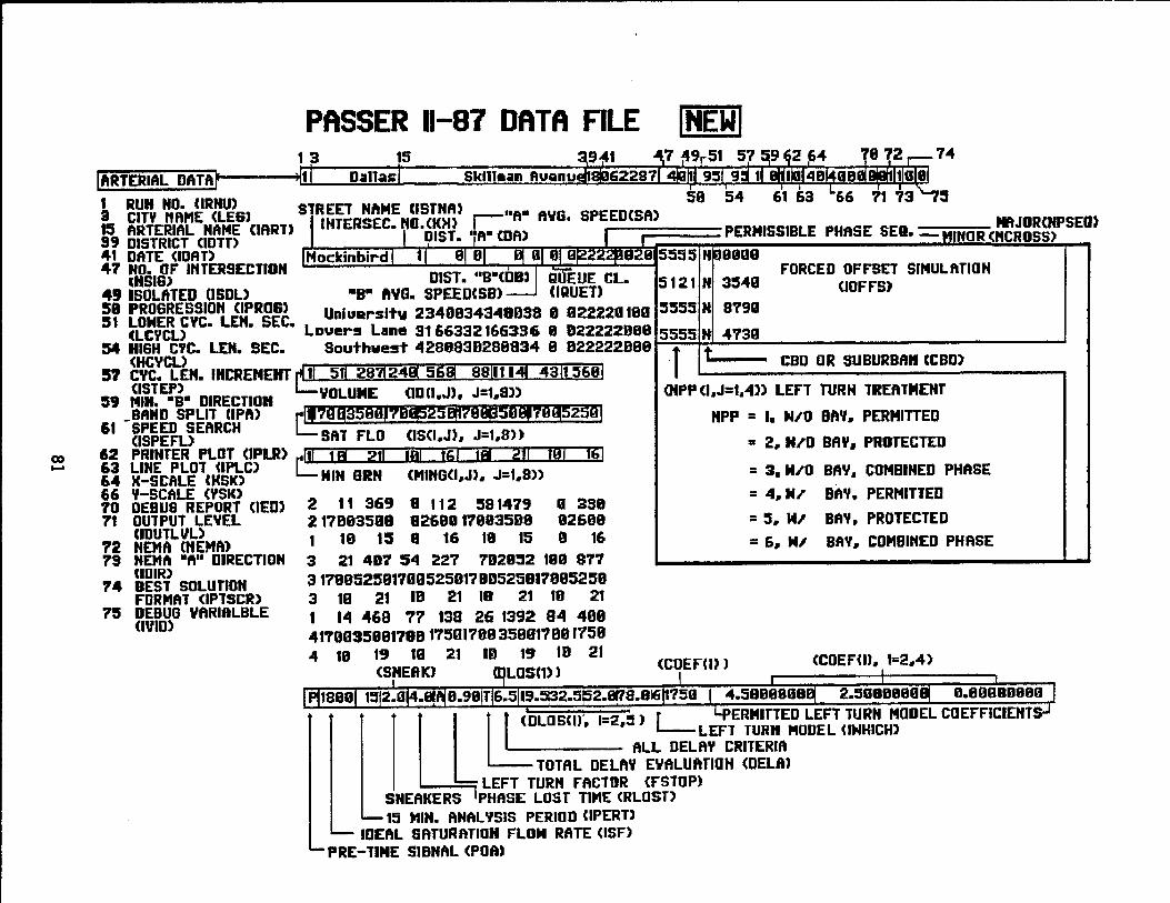
PASSER 11-87 DATA FILE 1 9 15
ARTERIAL DATA 1 D ... ll~Si 51<111 .... " Ruanu 5
L ~rT~ ~'k"~Rr..UJ&) STREET NAME CISTNA) II _
AYO. SPEEDCSft) 15 ARTERIAL NAME (IART) 99 DISTRICT (IDTD 41 DATE (IDAr>
·IINTERSEC. roo (K)I) r ft DIST. 'jft8 CDR)
NAJOR(NPSEO I I PERMISSIBLE PHASE SEll. -MINOR <"CROSS)
47 NO. OF INTERSECTION '"SIG)
49 ISOLATED (lSDL) 51 PROGRESSION (IPROS) :51 LONER CYC. LEN. SEC.
(LCYCL) 54 HIGH eyc. LEN. SEC.
IMockinbird 1 11 ·lJf 81 B! 01 01 8"''''''''828
DIST. "B-~~ QifEUE CL. -88 AVG. SPEED<SB) UQUETl
Uniuarslt ... 234083434803S " 022220180 Leuers Lane 3166332166336 8 022222088
Southwest 428883B288834 8 B22222888
5555 NI08008 FORCED OFFSET SIMULATION
5121 N 3:540 (IOFF'S)
:S:SS5 N B791
5555 N 4730
CBO OR SUBURBAII CCBD) <HCYCL> 57 eyc. LEN. IHCREMEHT rUt.
(ISTEP) C 1 t 1 511 281124i 5g§i 8811114 4311 :5681
:59 Mill. -B- DIRECTlOIi _BAND SPLIT CIPA)
61 SPEED SEARCH (ISPEFL>
VOLUME (10 n .J) • J=1.S)
IJ'1D ~§!jln'~'6i!j~!j ijt~lhESl'n'71~!j2~11 SAT FLO (IS(I.J) .. J=1 .. 8»
(NPP (I.J=1.4» LEFT TURN TREATMENT
NPP = I. NIO BAY. PERMITTED
62 PRINTER PLOT (IPLR) rUL 63 LINE PLOT ClPLC) L-64 H-SCAlE CKSK) 66 Y-SCALE ('1SK)
111 Iii 211 MIN aRN
101 i61 Ji 211 101 161 • 2 .. HI'D BAY. PROTECTED
(MIHG(I .. J). J=1.S» = 3. MI'O BAY. COMBINED PHASE
70 DEBUS REPORT (lED> 71 OUTPUT LEVEL
ClDUTL"L) '72 NEMA (HEMA) 7' NEM" 8ftll DIRECTION
ClDlR) 74 BEST SOLUTION
FORMAT (IPTSCR) '75 DEaUG VARlftLBLE
(IVIC>
2 11 369 8 112 ~8147' o :aS8 217093508 8269117893508 92608 1 19 15 8 16 19 15 9 16
3 21 407 504 227 7029~2 189 917 317895258170052591700525817885250 3 10 21 IB 21 18 21 18 21 1 ..... 469 77 138 26 1392 84 488 417903508178817501708358011001758 4 18 19 10 21 10 19 18 21
(SHEftKl mLOSm)
= 4. HI' BAY. PERMITTED
= ~ .. ... .1 BAY. PROTECTED
= 6 .. NJ' BAY .. COMBINED PHASE
(COEFm) (COEFUl. 1=2.4)
2.5080BBO 0.89980980
U ~(OU]5C1) 1=2:J) r ERMinED LEFT TURN MODEL COEFFICIEHT
• • '---LEFT TURn "OOEL UNHICH) ALL DELft? CRITERIA
TOTAL DELAY EVALUATIOH (DELft) LEFT TURN FACTOR (FSTOP)
SNEAKERS PHASE LOST TIME (RLOST> 15 MIH. ANAL 'iSIS PERla D (lPERn
IDEAL SATURATlOII FLOM RATE (ISF) PRE-TIME SIBNAL (POft)
)
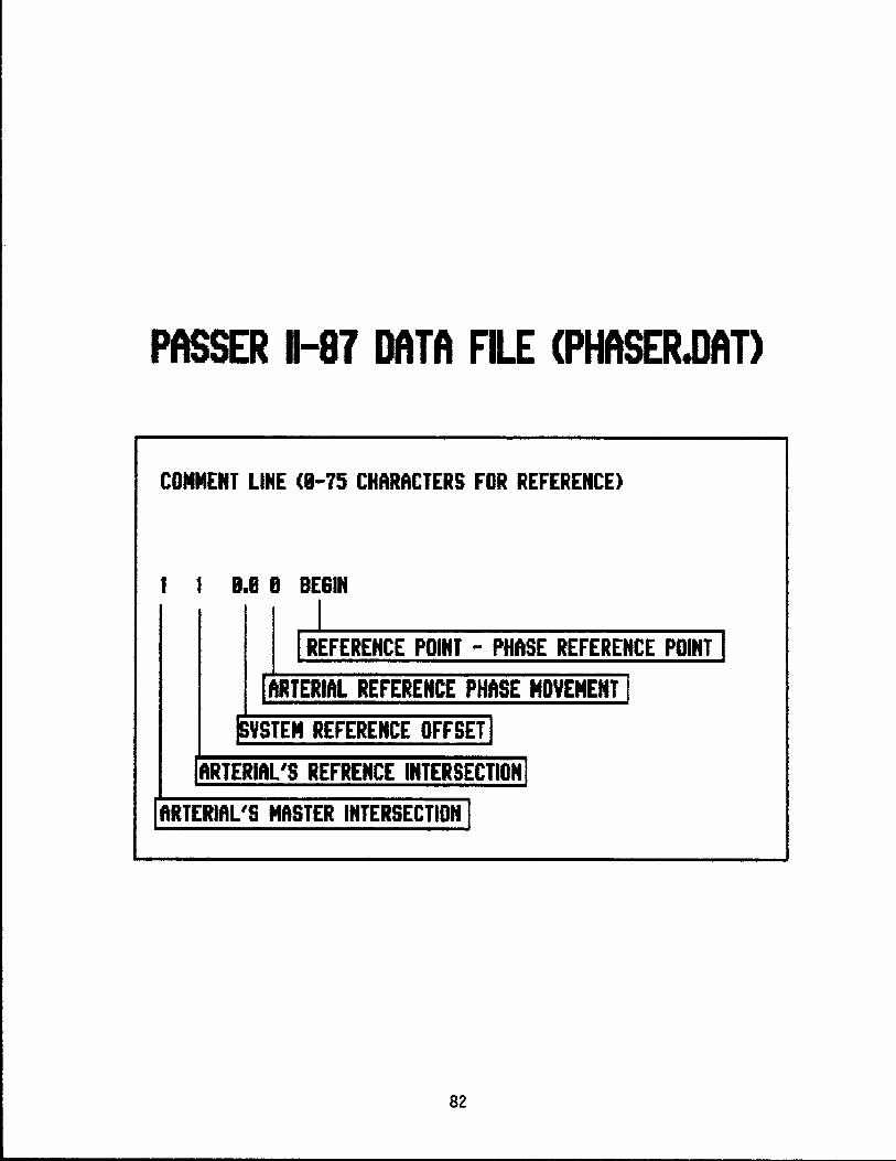
PASSER 11-87 DATA FILE (PHASER.DAT)
COMMENT LINE (8-75 CHARACTERS FOR REFERENCE)
1 1 8.8 B 8E61"
I I REFERENCE POINT - PHASE REFERENCE POINT I
I ARTERIAL REFERENCE PHASE MOVEMENT I ~YSTEM REFERENCE OFFSETJ
IARTERIAL'S REFRENCE INTERSECTION I I ARTERIAL'S MASTER INTERSECTION I
82
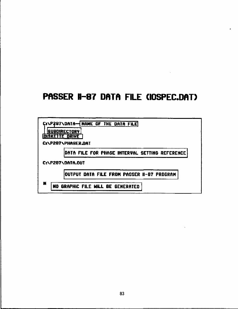
PASSER 11-87 DATA FILE (IOSPEC.DAT)
C.'P'87'DATA~ NAME OF THE DATA FILEt
ISUBDIRECTOR\, I UI19KETTE DRIVE I
C.'P28?'PHA8ER.DRT
IDATA FILE FOR PHASE INTERVAL SETTING REFERENCE I C:\.P297\.DATA.OUT
IOUTPUT DATA FILE FROM PASSER 11-81 PROGRAM I It I NO GRAPHIC FILE WILL BE GENERATED I
83
APPENDIX B.
Example Output of PASSER 11-87 Program.
84
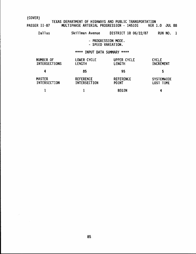
(COVER) TEXAS DEPARTMENT OF HIGHWAYS AND PUBLIC TRANSPORTATION
PASSER 11-87 MULTIPHASE ARTERIAL PROGRESSION - 145101 VER 1.0 JUL 88
Dall as Skillman Avenue DISTRICT 18 06/22/87 RUN NO. 1
- PROGRESSION'MODE. - SPEED VARIATION.
**** INPUT DATA SUMMARY ****
NUMBER OF LOWER CYCLE UPPER CYCLE CYCLE INTERSECTIONS LENGTH LENGTH INCREMENT
4 85 95 5
MASTER REFERENCE REFERENCE SYSTEMWIDE INTERSECTION INTERSECTION POINT LOST TIME
1 1 BEGIN 4
85
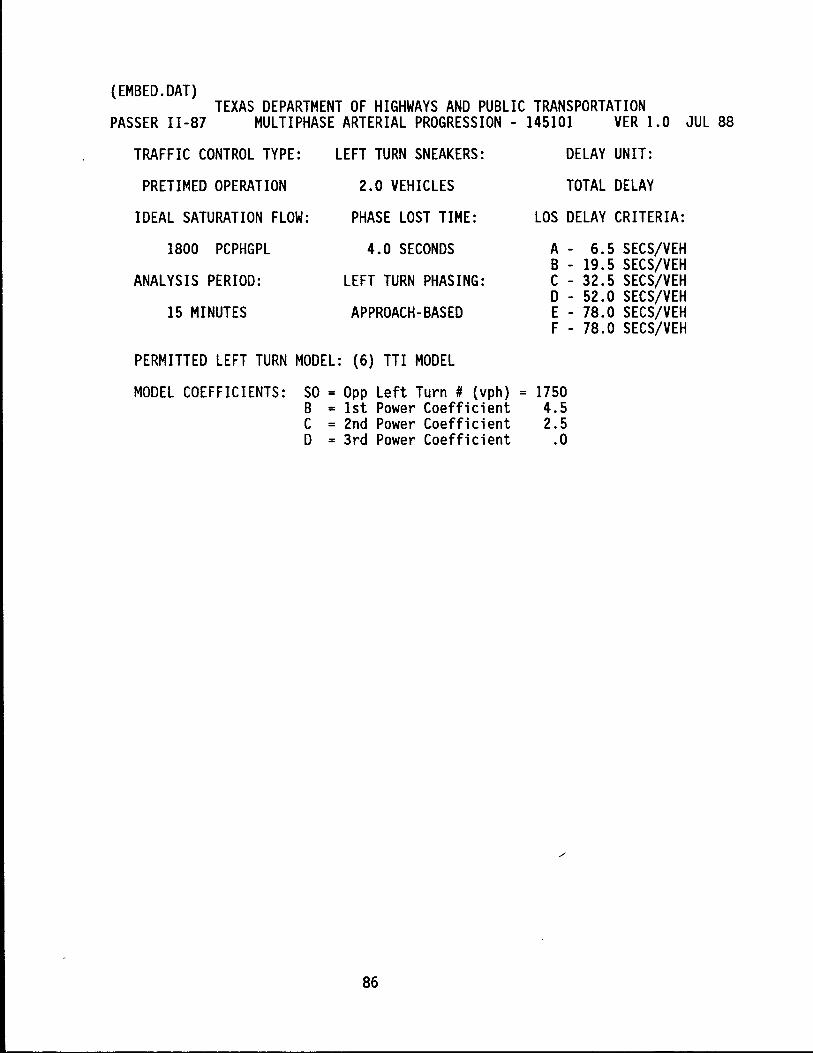
(EMBED. OAT) TEXAS DEPARTMENT OF HIGHWAYS AND PUBLIC TRANSPORTATION
PASSER 11-87 MULTIPHASE ARTERIAL PROGRESSION - 145101 VER 1.0 JUL 88
TRAFFIC CONTROL TYPE: LEFT TURN SNEAKERS: DELAY UNIT:
PRETIMED OPERATION 2.0 VEHICLES TOTAL DELAY
IDEAL SATURATION FLOW: PHASE LOST TIME: LOS DELAY CRITERIA:
1800 PCPHGPL 4.0 SECONDS A - 6.5 SECS/VEH B - 19.5 SECS/VEH
ANALYSIS PERIOD: LEFT TURN PHASING: C - 32.5 SECS/VEH o - 52.0 SECS/VEH
15 MINUTES APPROACH-BASED E - 78.0 SECS/VEH F - 78.0 SECS/VEH
PERMITTED LEFT TURN MODEL: (6) TTl MODEL
MODEL COEFFICIENTS: SO = Opp Left Turn # (vph) = 1750 B = 1st Power Coefficient 4.5 C = 2nd Power Coefficient 2.5 o = 3rd Power Coefficient .0
86
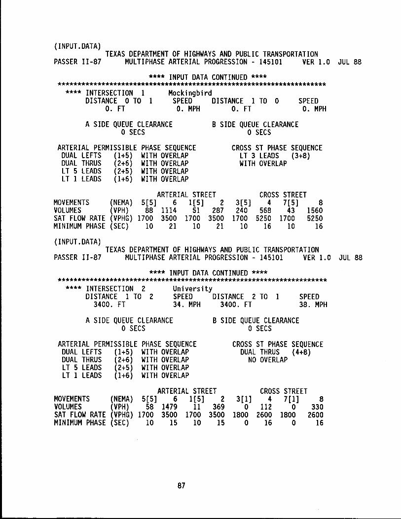
(INPUT.DATA) TEXAS DEPARTMENT OF HIGHWAYS AND PUBLIC TRANSPORTATION
PASSER 11-87 MULTIPHASE ARTERIAL PROGRESSION - 145101 VER 1.0 JUL 88
**** INPUT DATA CONTINUED **** ********************************************************************
Mockingbird **** INTERSECTION 1 DISTANCE 0 TO 1
o. FT SPEED DISTANCE 1 TO 0 SPEED
O. MPH O. MPH O. FT
A SIDE QUEUE CLEARANCE o SECS
B SIDE QUEUE CLEARANCE o SECS
ARTERIAL PERMISSIBLE PHASE SEQUENCE DUAL LEFTS (1+5) WITH OVERLAP DUAL THRUS (2+6) WITH OVERLAP LT 5 LEADS (2+5) WITH OVERLAP LT 1 LEADS (1+6) WITH OVERLAP
MOVEMENTS (NEMA) VOLUMES (VPH) SAT FLOW RATE (VPHG) MINIMUM PHASE (SEC)
(INPUT.DATA)
ARTERIAL STREET 5[5] 6 1[5] 2 88 1114 51 287
1700 3500 1700 3500 10 21 10 21
CROSS ST PHASE SEQUENCE LT 3 LEADS (3+8) WITH OVERLAP
3[5] 240
1700 10
CROSS STREET 4 7[5] 8
568 43 1560 5250 1700 5250
16 10 16
TEXAS DEPARTMENT OF HIGHWAYS AND PUBLIC TRANSPORTATION PASSER 11-87 MULTIPHASE ARTERIAL PROGRESSION - 145101 VER 1.0 JUL 88
**** INPUT DATA CONTINUED **** ********************************************************************
University **** INTERSECTION 2 DISTANCE 1 TO 2
3400. FT SPEED DISTANCE 2 TO 1 SPEED
38. MPH 34. MPH 3400. FT
A SIDE QUEUE CLEARANCE o SECS
B SIDE QUEUE CLEARANCE o SECS
ARTERIAL PERMISSIBLE PHASE SEQUENCE DUAL LEFTS (1+5) WITH OVERLAP DUAL THRUS (2+6) WITH OVERLAP LT 5 LEADS (2+5) WITH OVERLAP LT 1 LEADS (1+6) WITH OVERLAP
MOVEMENTS (NEMA) VOLUMES (VPH) SAT FLOW RATE (VPHG) MINIMUM PHASE (SEC)
ARTERIAL STREET 5[5] 6 1[5] 2
58 1479 11 369 1700 3500 1700 3500
10 15 10 15
87
CROSS ST PHASE SEQUENCE DUAL THRUS (4+8)
NO OVERLAP
3[1] o
1800 o
CROSS STREET 4 7[1] 8
112 0 330 2600 1800 2600
16 0 16
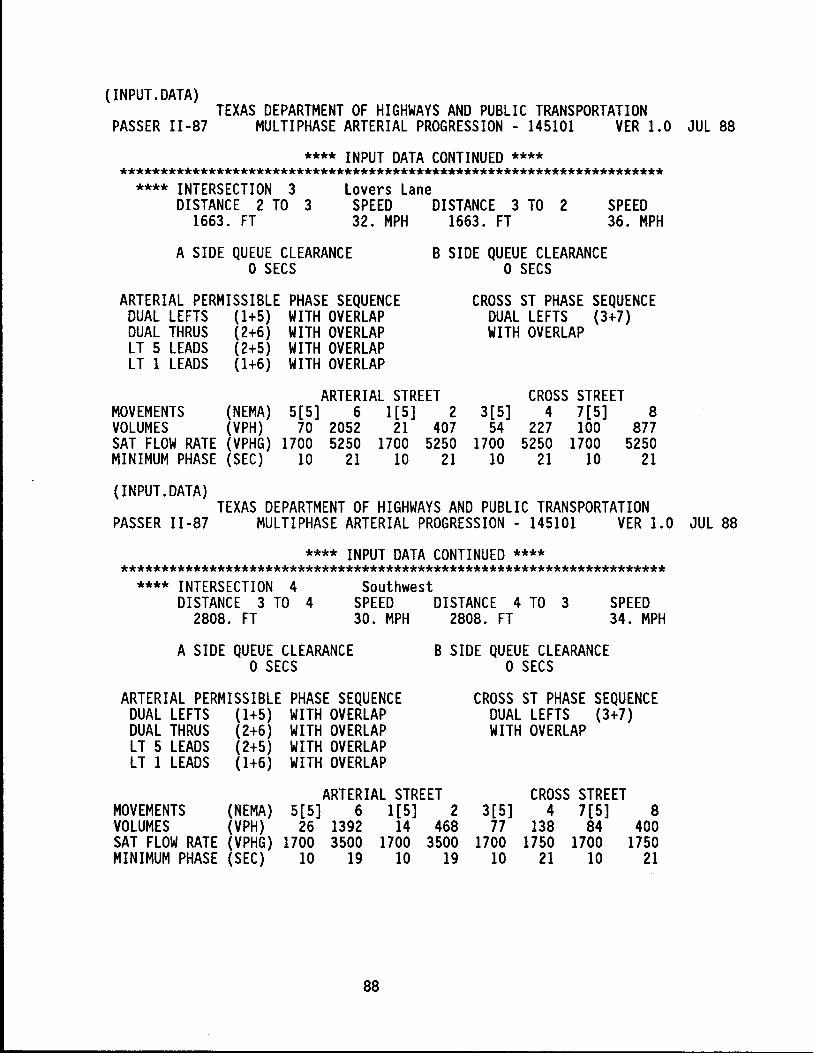
(INPUT.DATA) TEXAS DEPARTMENT OF HIGHWAYS AND PUBLIC TRANSPORTATION
PASSER 11-87 MULTIPHASE ARTERIAL PROGRESSION - 145101 VER 1.0 JUL 88
**** INPUT DATA CONTINUED **** ********************************************************************
Lovers Lane **** INTERSECTION 3 DISTANCE 2 TO 3
1663. FT SPEED DISTANCE 3 TO 2 SPEED
36. MPH 32. MPH 1663. FT
A SIDE QUEUE CLEARANCE o SECS
B SIDE QUEUE CLEARANCE o SECS
ARTERIAL PERMISSIBLE PHASE SEQUENCE DUAL LEFTS (1+5) WITH OVERLAP DUAL THRUS (2+6) WITH OVERLAP LT 5 LEADS (2+5) WITH OVERLAP LT 1 LEADS (1+6) WITH OVERLAP
MOVEMENTS (NEMA) VOLUMES (VPH) SAT FLOW RATE (VPHG) MINIMUM PHASE (SEC)
(INPUT.DATA)
ARTERIAL STREET 5[5] 6 1[5] 2
70 2052 21 407 1700 5250 1700 5250
10 21 10 21
CROSS ST PHASE SEQUENCE DUAL LEFTS (3+7) WITH OVERLAP
3[5] 54
1700 10
CROSS STREET 4 7 [5] 8
227 100 877 5250 1700 5250
21 10 21
TEXAS DEPARTMENT OF HIGHWAYS AND PUBLIC TRANSPORTATION PASSER 11-87 MULTIPHASE ARTERIAL PROGRESSION - 145101 VER 1.0 JUL 88
**** INPUT DATA CONTINUED **** ********************************************************************
Southwest **** INTERSECTION 4 DISTANCE 3 TO 4
2808. FT SPEED DISTANCE 4 TO 3 SPEED
34. MPH 30. MPH 2808. FT
A SIDE QUEUE CLEARANCE o SECS
B SIDE QUEUE CLEARANCE o SECS
ARTERIAL PERMISSIBLE PHASE SEQUENCE DUAL LEFTS (1+5) WITH OVERLAP DUAL THRUS (2+6) WITH OVERLAP LT 5 LEADS (2+5) WITH OVERLAP LT 1 LEADS (1+6) WITH OVERLAP
MOVEMENTS (NEMA) VOLUMES (VPH) SAT FLOW RATE (VPHG) MINIMUM PHASE (SEC)
ARTERIAL STREET 5[5] 6 1[5] 2
26 1392 14 468 1700 3500 1700 3500
10 19 10 19
88
CROSS ST PHASE SEQUENCE DUAL LEFTS (3+7) WITH OVERLAP
3[5] 77
1700 10
CROSS STREET 4 7[5] 8
138 84 400 1750 1700 1750
21 10 21
(ERROR.MSG) TEXAS DEPARTMENT OF HIGHWAYS AND PUBLIC TRANSPORTATION
PASSER 11-87 MULTIPHASE ARTERIAL PROGRESSION - 145101 VER 1.0 JUL 88
**** CODING ERROR MESSAGES ****
NO APPARENT CODING ERRORS
89
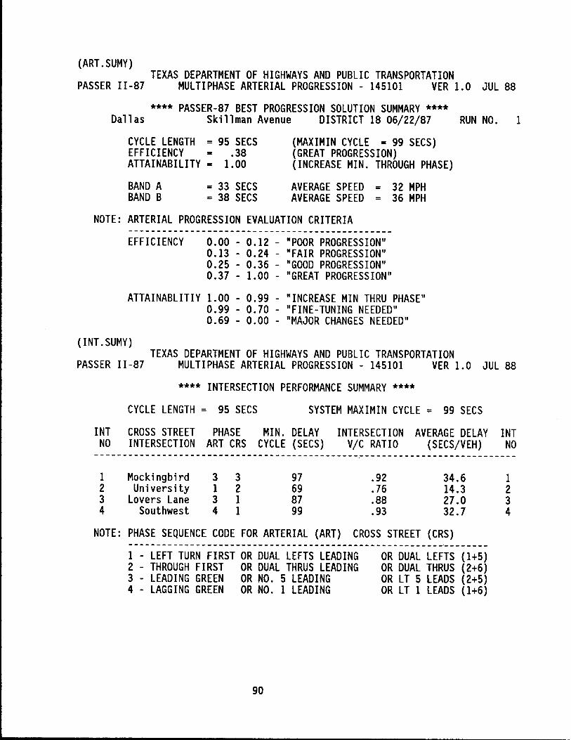
(ART.SUMY) TEXAS DEPARTMENT OF HIGHWAYS AND PUBLIC TRANSPORTATION
PASSER 11-87 MULTIPHASE ARTERIAL PROGRESSION - 145101 VER 1.0 JUL 88
**** PASSER-87 BEST PROGRESSION SOLUTION SUMMARY **** Dallas Skillman Avenue DISTRICT 18 06/22/87 RUN NO. 1
CYCLE LENGTH = 95 SECS EFFICIENCY = .38 ATTAINABILITY = 1.00
(MAXIMIN CYCLE = 99 SECS) (GREAT PROGRESSION) (INCREASE MIN. THROUGH PHASE)
BAND A BAND B
= 33 SECS = 38 SECS
AVERAGE SPEED = 32 MPH AVERAGE SPEED = 36 MPH
NOTE: ARTERIAL PROGRESSION EVALUATION CRITERIA
EFFICIENCY 0.00 - 0.12 - "POOR PROGRESSION" 0.13 - 0.24 - "FAIR PROGRESSION" 0.25 - 0.36 - "GOOD PROGRESSION" 0.37 - 1.00 - "GREAT PROGRESSION"
ATTAINABLITIY 1.00 - 0.99 - "INCREASE MIN THRU PHASE"
(INT.SUMY)
0.99 - 0.70 - "FINE-TUNING NEEDED" 0.69 - 0.00 - "MAJOR CHANGES NEEDED"
TEXAS DEPARTMENT OF HIGHWAYS AND PUBLIC TRANSPORTATION PASSER 11-87 MULTIPHASE ARTERIAL PROGRESSION - 145101 VER 1.0 JUL 88
**** INTERSECTION PERFORMANCE SUMMARY ****
CYCLE LENGTH = 95 SECS SYSTEM MAXIMIN CYCLE = 99 SECS
INT CROSS STREET PHASE MIN. DELAY INTERSECTION AVERAGE DELAY INT NO INTERSECTION ART CRS CYCLE (SECS) VIC RATIO (SECS/VEH) NO
1 2 3 4
NOTE:
Mockingbird 3 3 97 .92 34.6 University 1 2 69 .76 14.3
Lovers Lane 3 1 87 .88 27.0 Southwest 4 1 99 .93 32.7
PHASE SEQUENCE CODE FOR ARTERIAL (ART) CROSS STREET (CRS) ----------------------------------------------------------------1 - LEFT TURN FIRST OR DUAL LEFTS LEADING 2 - THROUGH FIRST OR DUAL THRUS LEADING 3 - LEADING GREEN OR NO. 5 LEADING 4 - LAGGING GREEN OR NO. 1 LEADING
90
OR DUAL LEFTS (1+5) OR DUAL THRUS (2+6) OR LT 5 LEADS (2+5) OR LT 1 LEADS (1+6)
1 2 3 4
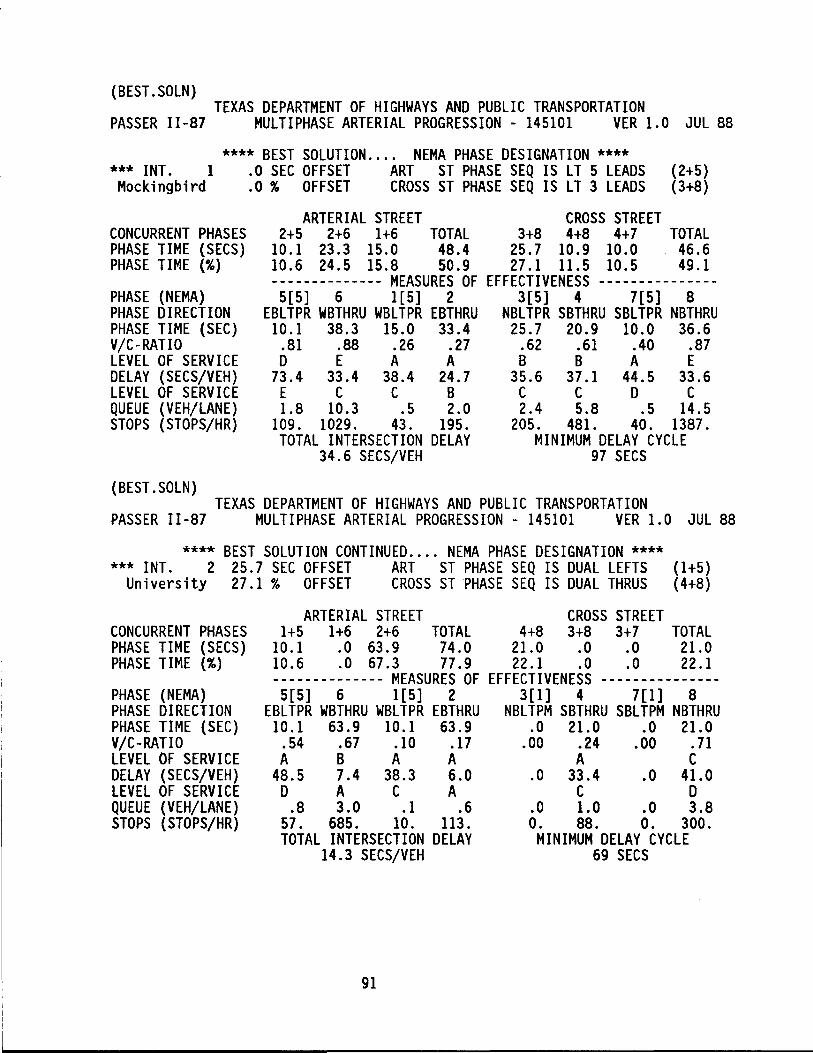
(BEST.SOLN) TEXAS DEPARTMENT OF HIGHWAYS AND PUBLIC TRANSPORTATION
PASSER 11-87 MULTIPHASE ARTERIAL PROGRESSION - 145101 VER 1.0 JUL 88
**** BEST SOLUTION .... NEMA PHASE DESIGNATION **** *** INT. 1 .0 SEC OFFSET ART ST PHASE SEQ IS LT 5 LEADS (2+5) Mockingbird .0 % OFFSET CROSS ST PHASE SEQ IS LT 3 LEADS (3+8)
CONCURRENT PHASES PHASE TIME (SECS) PHASE TIME (%)
PHASE (NEMA) PHASE DIRECTION PHASE TIME (SEC) V/C-RATIO LEVEL OF SERVICE DELAY (SECS/VEH) LEVEL OF SERVICE QUEUE (VEH/LANE) STOPS (STOPS/HR)
(BEST.SOLN)
ARTERIAL STREET CROSS STREET 2+5 2+6 1+6 TOTAL 3+8 4+8 4+7 TOTAL
10.1 23.3 15.0 48.4 25.7 10.9 10.0 46.6 10.6 24.5 15.8 50.9 27.1 11.5 10.5 49.1 -------------- MEASURES OF EFFECTIVENESS ---------------5[5] 6 1[5] 2 3[5] 4 7[5] 8
EBLTPR WBTHRU WBLTPR EBTHRU NBLTPR SBTHRU SBLTPR NBTHRU 10.1 38.3 15.0 33.4 25.7 20.9 10.0 36.6
.81 .88 .26 .27 .62 .61 .40 .87 D E A A B B A E
73.4 33.4 38.4 24.7 35.6 37.1 44.5 33.6 E C C B C CDC 1.8 10.3 .5 2.0 2.4 5.8 .5 14.5
109. 1029. 43. 195. 205. 481. 40. 1387. TOTAL INTERSECTION DELAY MINIMUM DELAY CYCLE
34.6 SECS/VEH 97 SECS
TEXAS DEPARTMENT OF HIGHWAYS AND PUBLIC TRANSPORTATION PASSER 11-87 MULTIPHASE ARTERIAL PROGRESSION - 145101 VER 1.0 JUL 88
**** BEST SOLUTION CONTINUED .... NEMA PHASE DESIGNATION **** *** INT. 2 25.7 SEC OFFSET ART ST PHASE SEQ IS DUAL LEFTS (1+5)
University 27.1 % OFFSET CROSS ST PHASE SEQ IS DUAL THRUS (4+8)
CONCURRENT PHASES PHASE TIME (SECS) PHASE TIME (%)
PHASE (NEMA) PHASE DIRECTION PHASE TIME (SEC) V/C-RATIO LEVEL OF SERVICE DELAY (SECS/VEH) LEVEL OF SERVICE QUEUE (VEH/lANE) STOPS (STOPS/HR)
ARTERIAL STREET CROSS STREET 1+5 1+6 2+6 TOTAL 4+8 3+8 3+7 TOTAL
10.1 .0 63.9 74.0 21.0 .0 .0 21.0 10.6 .0 67.3 77.9 22.1 .0 .0 22.1 -------------- MEASURES OF EFFECTIVENESS ---------------5[5] 6 1[5] 2 3[1] 4 7[1] 8
EBLTPR WBTHRU WBLTPR EBTHRU NBLTPM SBTHRU SBLTPM NBTHRU 10.1 63.9 10.1 63.9 .0 21.0 .0 21.0 .54 .67 .10 .17 .00 .24 .00 .71 A B A A A C
48.5 7.4 38.3 6.0 .0 33.4 .0 41.0 D A C A C D
.8 3.0 .1 .6 .0 1.0 .0 3.8 57. 685. 10. 113. O. 88. O. 300. TOTAL INTERSECTION DELAY MINIMUM DELAY CYCLE
14.3 SECS/VEH 69 SECS
91
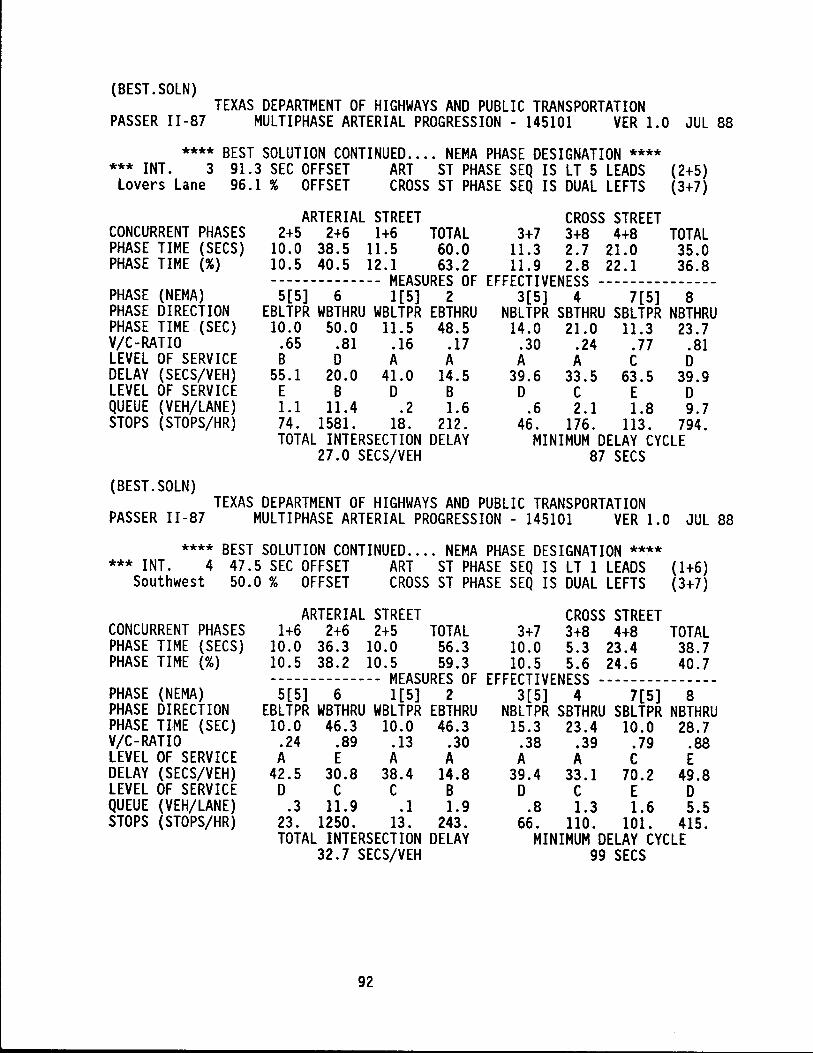
(BEST.SOLN) TEXAS DEPARTMENT OF HIGHWAYS AND PUBLIC TRANSPORTATION
PASSER 11-87 MULTIPHASE ARTERIAL PROGRESSION - 145101 VER 1.0 JUL 88
**** BEST SOLUTION CONTINUED .... NEMA PHASE DESIGNATION **** *** INT. 3 91.3 SEC OFFSET ART ST PHASE SEQ IS LT 5 LEADS (2+5)
Lovers Lane 96.1 % OFFSET CROSS ST PHASE SEQ IS DUAL LEFTS (3+7)
CONCURRENT PHASES PHASE TIME (SECS) PHASE TIME (%)
PHASE (NEMA) PHASE DIRECTION PHASE TIME (SEC) V/C-RATIO LEVEL OF SERVICE DELAY (SECS/VEH) LEVEL OF SERVICE QUEUE (VEH/LANE) STOPS (STOPS/HR)
(BEST.SOLN)
ARTERIAL STREET CROSS STREET 2+5 2+6 1+6 TOTAL 3+7 3+8 4+8 TOTAL
10.0 38.5 11.5 60.0 11.3 2.7 21.0 35.0 10.5 40.5 12.1 63.2 11.9 2.8 22.1 36.8 -------------- MEASURES OF EFFECTIVENESS ---------------5[5] 6 1[5] 2 3[5] 4 7[5] 8
EBLTPR WBTHRU WBLTPR EBTHRU NBLTPR SBTHRU SBLTPR NBTHRU 10.0 50.0 11.5 48.5 14.0 21.0 11.3 23.7
.65 .81 .16 .17 .30 .24 .77 .81 B D A A A A C D
55.1 20.0 41.0 14.5 39.6 33.5 63.5 39.9 E B D B D C E D 1.1 11.4 .2 1.6 .6 2.1 1.8 9.7 74. 1581. 18. 212. 46. 176. 113. 794. TOTAL INTERSECTION DELAY MINIMUM DELAY CYCLE
27.0 SECS/VEH 87 SECS
TEXAS DEPARTMENT OF HIGHWAYS AND PUBLIC TRANSPORTATION PASSER 11-87 MULTIPHASE ARTERIAL PROGRESSION - 145101 VER 1.0 JUL 88
**** BEST SOLUTION CONTINUED .... NEMA PHASE DESIGNATION **** *** INT. 4 47.5 SEC OFFSET ART ST PHASE SEQ IS LT 1 LEADS (1+6)
Southwest 50.0 % OFFSET CROSS ST PHASE SEQ IS DUAL LEFTS (3+7)
CONCURRENT PHASES PHASE TIME (SECS) PHASE TIME (%)
PHASE (NEMA) PHASE DIRECTION PHASE TIME (SEC) V/C-RATIO LEVEL OF SERVICE DELAY (SECS/VEH) LEVEL OF SERVICE QUEUE (VEH/LANE) STOPS (STOPS/HR)
ARTERIAL STREET CROSS STREET 1+6 2+6 2+5 TOTAL 3+7 3+8 4+8 TOTAL
10.0 36.3 10.0 56.3 10.0 5.3 23.4 38.7 10.5 38.2 10.5 59.3 10.5 5.6 24.6 40.7 -------------- MEASURES OF EFFECTIVENESS ---------------5[5] 6 1[5] 2 3[5] 4 7[5] 8
EBLTPR WBTHRU WBLTPR EBTHRU NBLTPR SBTHRU SBLTPR NBTHRU 10.0 46.3 10.0 46.3 15.3 23.4 10.0 28.7
.24 .89 .13 .30 .38 .39 .79 .88 A E A A A ACE
42.5 30.8 38.4 14.8 39.4 33.1 70.2 49.8 D C C B D C E D
.3 11.9 .1 1.9 .8 1.3 1.6 5.5 23. 1250. 13. 243. 66. 110. 101. 415. TOTAL INTERSECTION DELAY MINIMUM DELAY CYCLE
32.7 SECS/VEH 99 SECS
92
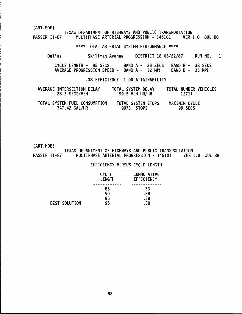
(ART.MOE) TEXAS DEPARTMENT OF HIGHWAYS AND PUBLIC TRANSPORTATION
PASSER 11-87 MULTIPHASE ARTERIAL PROGRESSION - 145101 VER 1.0 JUL 88
**** TOTAL ARTERIAL SYSTEM PERFORMANCE ****
Dallas Ski 11 man Avenue DISTRICT 18 06/22/87 RUN NO. 1
CYCLE LENGTH = 95 SECS BAND A = 33 SECS BAND B = 38 SECS AVERAGE PROGRESSION SPEED - BAND A = 32 MPH BAND B = 36 MPH
.38 EFFICIENCY 1.00 ATTAINABILITY
AVERAGE INTERSECTION DELAY TOTAL SYSTEM DELAY TOTAL NUMBER VEHICLES 28.2 SECS/VEH 99.5 VEH-HR/HR 12717.
TOTAL SYSTEM FUEL CONSUMPTION TOTAL SYSTEM STOPS MAXIMIN CYCLE 347.42 GAL/HR 9973. STOPS 99 SECS
(ART.MOE) TEXAS DEPARTMENT OF HIGHWAYS AND PUBLIC TRANSPORTATION
PASSER 11-87 MULTIPHASE ARTERIAL PROGRESSION - 145101 VER 1.0 JUL 88
BEST SOLUTION
EFFICIENCY VERSUS CYCLE LENGTH
CYCLE LENGTH
85 90 95 95
93
CUMMULATIVE EFFICIENCY
.33
.38
.38
.38
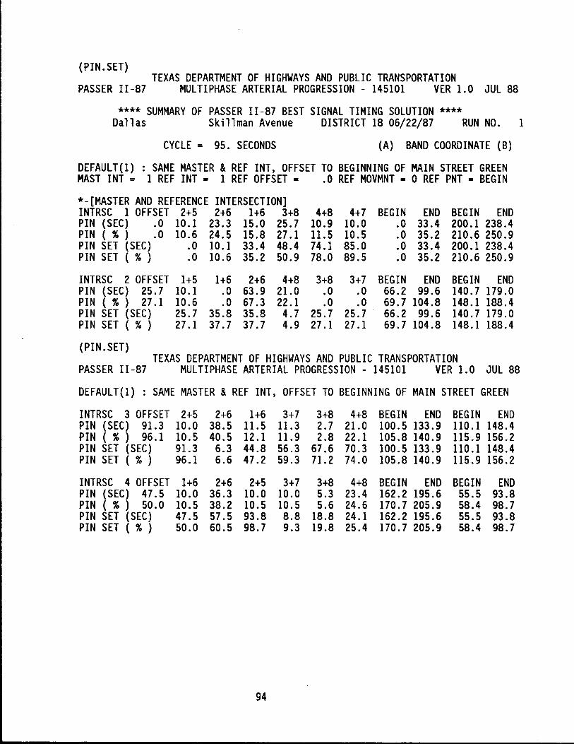
(PIN.SET) TEXAS DEPARTMENT OF HIGHWAYS AND PUBLIC TRANSPORTATION
PASSER 11-87 MULTIPHASE ARTERIAL PROGRESSION - 145101 VER 1.0 JUL 88
**** SUMMARY OF PASSER 11-87 BEST SIGNAL TIMING SOLUTION **** Dallas Skillman Avenue DISTRICT 18 06/22/87 RUN NO. 1
CYCLE = 95. SECONDS (A) BAND COORDINATE (B)
DEFAULT(l) : SAME MASTER & REF INT, OFFSET TO BEGINNING OF MAIN STREET GREEN MAST INT = 1 REF INT = 1 REF OFFSET = .0 REF MOVMNT = 0 REF PNT = BEGIN
*-[MASTER AND REFERENCE INTERSECTION] INTRSC 1 OFFSET 2+5 2+6 1+6 3+8 4+8 4+7 BEGIN END BEGIN END PIN (SEC) .0 10.1 23.3 15.0 25.7 10.9 10.0 .0 33.4 200.1 238.4 PIN ( % ) .0 10.6 24.5 15.8 27.1 11.5 10.5 .0 35.2 210.6 250.9 PIN SET (SEC) .0 10.1 33.4 48.4 74.1 85.0 .0 33.4 200.1 238.4 PIN SET ( % ) .0 10.6 35.2 50.9 78.0 89.5 .0 35.2 210.6 250.9
INTRSC 2 OFFSET 1+5 1+6 2+6 4+8 3+8 3+7 BEGIN END BEGIN END PIN (SEC) 25.7 10.1 .0 63.9 21.0 .0 .0 66.2 99.6 140.7 179.0 PIN ( % ) 27.1 10.6 .0 67.3 22.1 .0 .0 69.7 104.8 148.1 188.4 PIN SET (SEC) 25.7 35.8 35.8 4.7 25.7 25.7 66.2 99.6 140.7 179.0 PIN SET ( % ) 27.1 37.7 37.7 4.9 27.1 27.1 69.7 104.8 148.1 188.4
(PIN.SET) TEXAS DEPARTMENT OF HIGHWAYS AND PUBLIC TRANSPORTATION
PASSER 11-87 MULTIPHASE ARTERIAL PROGRESSION - 145101 VER 1.0 JUL 88
DEFAULT(l) : SAME MASTER & REF INT, OFFSET TO BEGINNING OF MAIN STREET GREEN
INTRSC 3 OFFSET 2+5 2+6 1+6 3+7 3+8 4+8 BEGIN END BEGIN END PIN (SEC) 91.3 10.0 38.5 11.5 11.3 2.7 21.0 100.5 133.9 110.1 148.4 PIN ( % ) 96.1 10.5 40.5 12.1 11.9 2.8 22.1 105.8 140.9 115.9 156.2 PIN SET (SEC) 91.3 6.3 44.8 56.3 67.6 70.3 100.5 133.9 110.1 148.4 PIN SET ( % ) 96.1 6.6 47.2 59.3 71.2 74.0 105.8 140.9 115.9 156.2
INTRSC 4 OFFSET 1+6 2+6 2+5 3+7 3+8 4+8 BEGIN END BEGIN END PIN (SEC) 47.5 10.0 36.3 10.0 10.0 5.3 23.4 162.2 195.6 55.5 93.8 PIN ( % ) 50.0 10.5 38.2 10.5 10.5 5.6 24.6 170.7 205.9 58.4 98.7 PIN SET (SEC) 47.5 57.5 93.8 8.8 18.8 24.1 162.2 195.6 55.5 93.8 PIN SET ( % ) 50.0 60.5 98.7 9.3 19.8 25.4 170.7 205.9 58.4 98.7
94
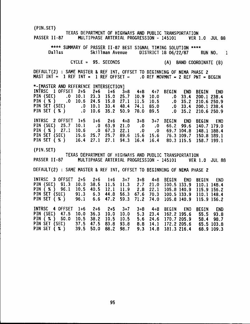
(PIN.SET) TEXAS DEPARTMENT OF HIGHWAYS AND PUBLIC TRANSPORTATION
PASSER 11-87 MULTIPHASE ARTERIAL PROGRESSION - 145101 VER 1.0 JUL 88
**** SUMMARY OF PASSER 11-87 BEST SIGNAL TIMING SOLUTION **** Dallas Skillman Avenue DISTRICT 18 06/22/87 RUN NO. 1
CYCLE = 95. SECONDS (A) BAND COORDINATE (B)
DEFAULT(2) : SAME MASTER & REF INT, OFFSET TO BEGINNING OF NEMA PHASE 2 MAST INT = 1 REF INT = 1 REF OFFSET = .0 REF MOVMNT = 2 REF PNT = BEGIN
*-[MASTER AND REFERENCE INTERSECTION] INTRSC 1 OFFSET 2+5 2+6 1+6 3+8 4+8 4+7 BEGIN END BEGIN END PIN (SEC) .0 10.1 23.3 15.0 25.7 10.9 10.0 .0 33.4 200.1 238.4 PIN ( % ) .0 10.6 24.5 15.8 27.1 11.5 10.5 .0 35.2 210.6 250.9 PIN SET (SEC) .0 10.1 33.4 48.4 74.1 85.0 .0 33.4 200.1 238.4 PIN SET ( % ) .0 10.6 35.2 50.9 78.0 89.5 .0 35.2 210.6 250.9
INTRSC 2 OFFSET 1+5 1+6 2+6 4+8 3+8 3+7 BEGIN END BEGIN END PIN (SEC) 25.7 10.1 .0 63.9 21.0 .0 .0 66.2 99.6 140.7 179.0 PIN ( % ) 27.1 10.6 .0 67.3 22.1 .0 .0 69.7 104.8 148.1 188.4 PIN SET (SEC) 15.6 25.7 25.7 89.6 15.6 15.6 76.3 109.7 150.8 189.1 PIN SET ( % ) 16.4 27.1 27.1 94.3 16.4 16.4 80.3 115.5 158.7 199.1
(PIN. SET) TEXAS DEPARTMENT OF HIGHWAYS AND PUBLIC TRANSPORTATION
PASSER II -87 MULTIPHASE ARTERIAL PROGRESSION - 145101 VER 1.0 JUL 88
DEFAULT(2) : SAME MASTER & REF INT, OFFSET TO BEGINNING OF NEMA PHASE 2
INTRSC 3 OFFSET 2+5 2+6 1+6 3+7 3+8 4+8 BEGIN END BEGIN END PIN (SEC) 91.3 10.0 38.5 11.5 11.3 2.7 21.0 100.5 133.9 110.1 148.4 PIN ( % ) 96.1 10.5 40.5 12.1 11.9 2.8 22.1 105.8 140.9 115.9 156.2 PIN SET (SEC) 91.3 6.3 44.8 56.3 67.6 70.3 100.5 133.9 110.1 148.4 PIN SET ( % ) 96.1 6.6 47.2 59.3 71.2 74.0 105.8 140.9 115.9 156.2
INTRSC 4 OFFSET 1+6 2+6 2+5 3+7 3+8 4+8 BEGIN END BEGIN END PIN (SEC) 47.5 10.0 36.3 10.0 10.0 5.3 23.4 162.2 195.6 55.5 93.8 PIN ( % ) 50.0 10.5 38.2 10.5 10.5 5.6 24.6 170.7 205.9 58.4 98.7 PIN SET (SEC) 37.5 47.5 83.8 93.8 8.8 14.1 172.2 205.6 65.5 103.8 PIN SET ( % ) 39.5 50.0 88.2 98.7 9.3 14.8 181.3 216.4 68.9 109.3
95
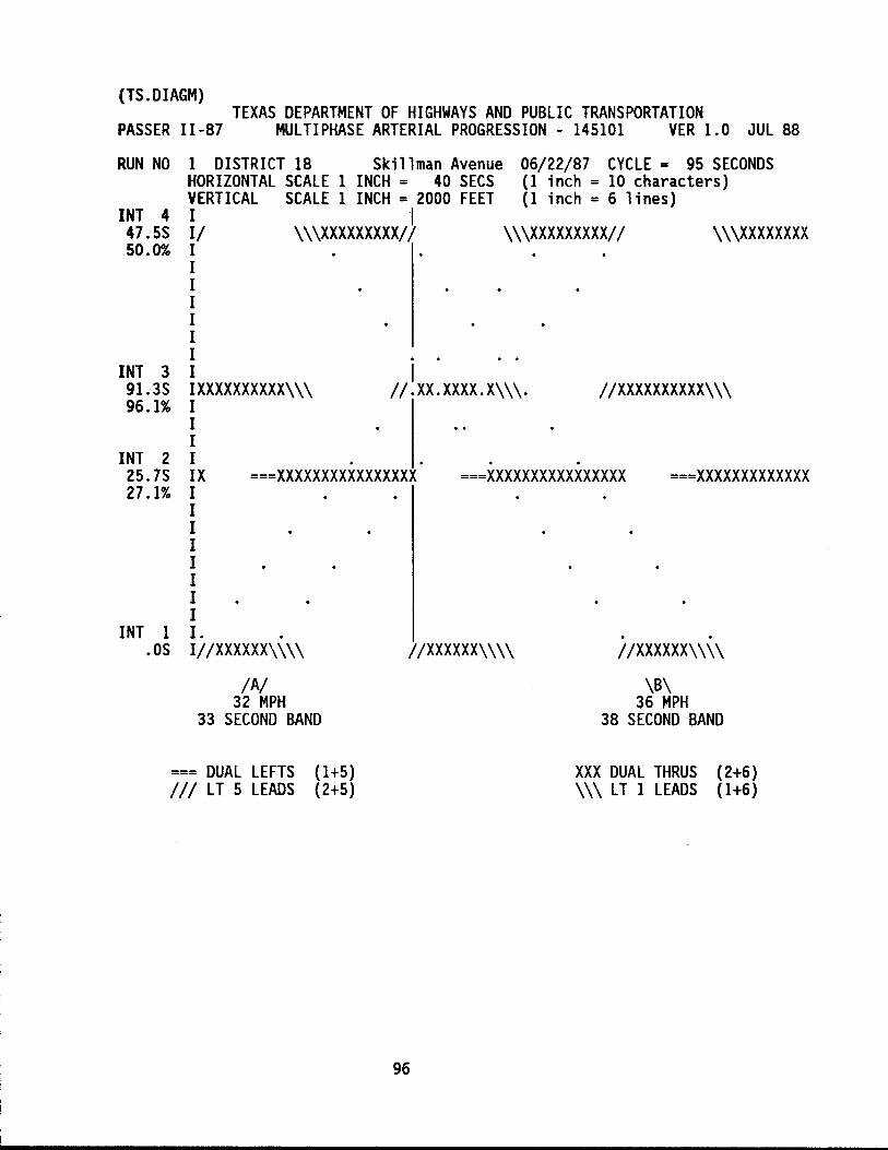
(TS.DIAGM) TEXAS DEPARTMENT OF HIGHWAYS AND PUBLIC TRANSPORTATION
PASSER 11-87 MULTIPHASE ARTERIAL PROGRESSION - 145101 VER 1.0 JUL 88
RUN NO
INT 4 47.5S 50.0%
INT 3 91.3S 96.1%
INT 2 25.7S 27.1%
INT 1 .OS
1 DISTRICT 18 Skillman Avenue HORIZONTAL SCALE 1 INCH = 40 SECS VERTICAL SCALE 1 INCH = 2000 FEET I I II \\\XXXXXXXXXII I I I I I I I
06/22/87 CYCLE = 95 SECONDS (1 inch = 10 characters) (1 inch = 6 lines)
\\\XXXXXXXXXII \\\XXXXXXXX
I IXXXXXXXXXX\\\ I
I II·XX.XXXX.X\\\. IIXXXXXXXXXX\\\
I I I IX I I I I I I I I
. ===XXXXXXXXXXXXXXXX
. . ===XXXXXXXXXXXXXXXX ===XXXXXXXXXXXXX
. . I. . IIIXXXXXX\\\\ IIXXXXXX\\\\ IIXXXXXX\\\\
IAI 32 MPH
33 SECOND BAND
\B\ 36 MPH
38 SECOND BAND
=== DUAL LEFTS (1+5) III LT 5 LEADS (2+5)
XXX DUAL THRUS (2+6) \\\ LT 1 LEADS (1+6)
96