Embed Size (px)
Citation preview

ARM HOW-TO GUIDE
Interfacing Keypad
with LPC2148 ARM
Join the Technical Community Today!
http://www.pantechsolutions.net
Contents at a Glance
ARM7 LPC2148 Primer Board ........................................... 3
Keypad ............................................................................ 3
Interfacing keypad ........................................................... 4
Interfacing keypad with LPC2148 ..................................... 6
Pin Assignment with LPC2148 .......................................... 6
Circuit Diagram to Interface keypad with LPC2148 ........... 7
Source Code .................................................................... 7
C Program to 4 X 4 matrix keypad using LPC2148 ............. 8
Testing the Keypad with LPC2148................................... 10
General Information ...................................................... 11
Join the Technical Community Today!
http://www.pantechsolutions.net
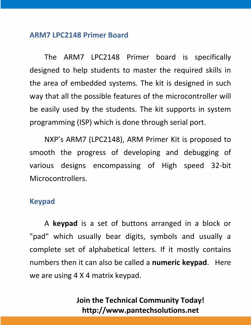
ARM7 LPC2148 Primer Board
The ARM7 LPC2148 Primer board is specifically
designed to help students to master the required skills in
the area of embedded systems. The kit is designed in such
way that all the possible features of the microcontroller will
be easily used by the students. The kit supports in system
programming (ISP) which is done through serial port.
NXP’s ARM7 (LPC2148), ARM Primer Kit is proposed to
smooth the progress of developing and debugging of
various designs encompassing of High speed 32-bit
Microcontrollers.
Keypad
A keypad is a set of buttons arranged in a block or
"pad" which usually bear digits, symbols and usually a
complete set of alphabetical letters. If it mostly contains
numbers then it can also be called a numeric keypad. Here
we are using 4 X 4 matrix keypad.
Join the Technical Community Today!
http://www.pantechsolutions.net
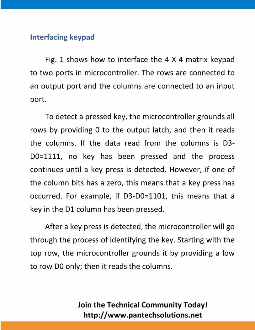
Interfacing keypad
Fig. 1 shows how to interface the 4 X 4 matrix keypad
to two ports in microcontroller. The rows are connected to
an output port and the columns are connected to an input
port.
To detect a pressed key, the microcontroller grounds all
rows by providing 0 to the output latch, and then it reads
the columns. If the data read from the columns is D3-
D0=1111, no key has been pressed and the process
continues until a key press is detected. However, if one of
the column bits has a zero, this means that a key press has
occurred. For example, if D3-D0=1101, this means that a
key in the D1 column has been pressed.
After a key press is detected, the microcontroller will go
through the process of identifying the key. Starting with the
top row, the microcontroller grounds it by providing a low
to row D0 only; then it reads the columns.
Join the Technical Community Today!
http://www.pantechsolutions.net
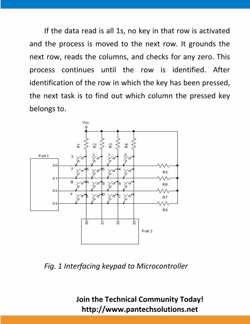
If the data read is all 1s, no key in that row is activated
and the process is moved to the next row. It grounds the
next row, reads the columns, and checks for any zero. This
process continues until the row is identified. After
identification of the row in which the key has been pressed,
the next task is to find out which column the pressed key
belongs to.
Fig. 1 Interfacing keypad to Microcontroller
Join the Technical Community Today!
http://www.pantechsolutions.net
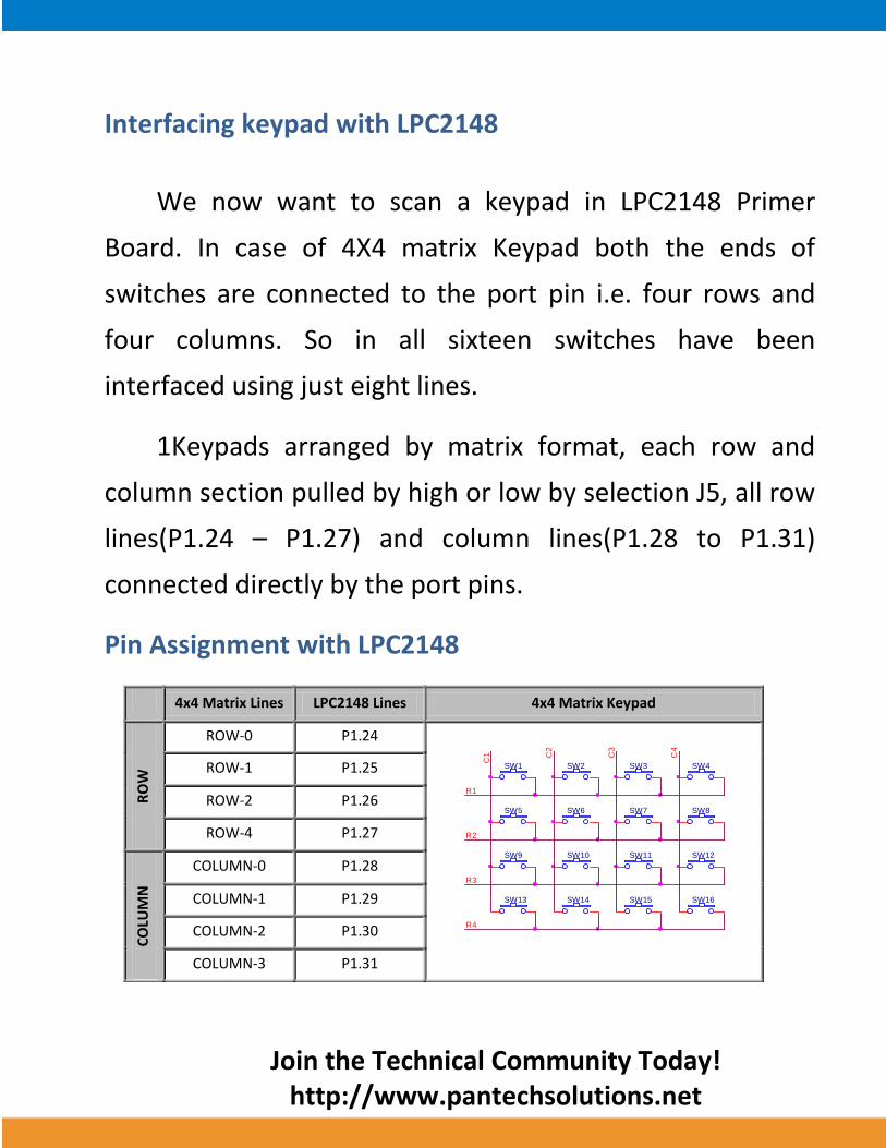
Interfacing keypad with LPC2148
We now want to scan a keypad in LPC2148 Primer
Board. In case of 4X4 matrix Keypad both the ends of
switches are connected to the port pin i.e. four rows and
four columns. So in all sixteen switches have been
interfaced using just eight lines.
1Keypads arranged by matrix format, each row and
column section pulled by high or low by selection J5, all row
lines(P1.24 – P1.27) and column lines(P1.28 to P1.31)
connected directly by the port pins.
Pin Assignment with LPC2148
4x4 Matrix Lines LPC2148 Lines 4x4 Matrix Keypad
RO
W
ROW-0 P1.24
ROW-1 P1.25
ROW-2 P1.26
ROW-4 P1.27
CO
LUM
N
COLUMN-0 P1.28
COLUMN-1 P1.29
COLUMN-2 P1.30
COLUMN-3 P1.31
R4
SW1
SW2
SW5
SW3
SW6
SW4
SW7 SW8
SW9 SW10 SW11 SW12
SW14SW13
C1
SW15
C4
SW16
C3
C2
R1
R3
R2
Join the Technical Community Today!
http://www.pantechsolutions.net
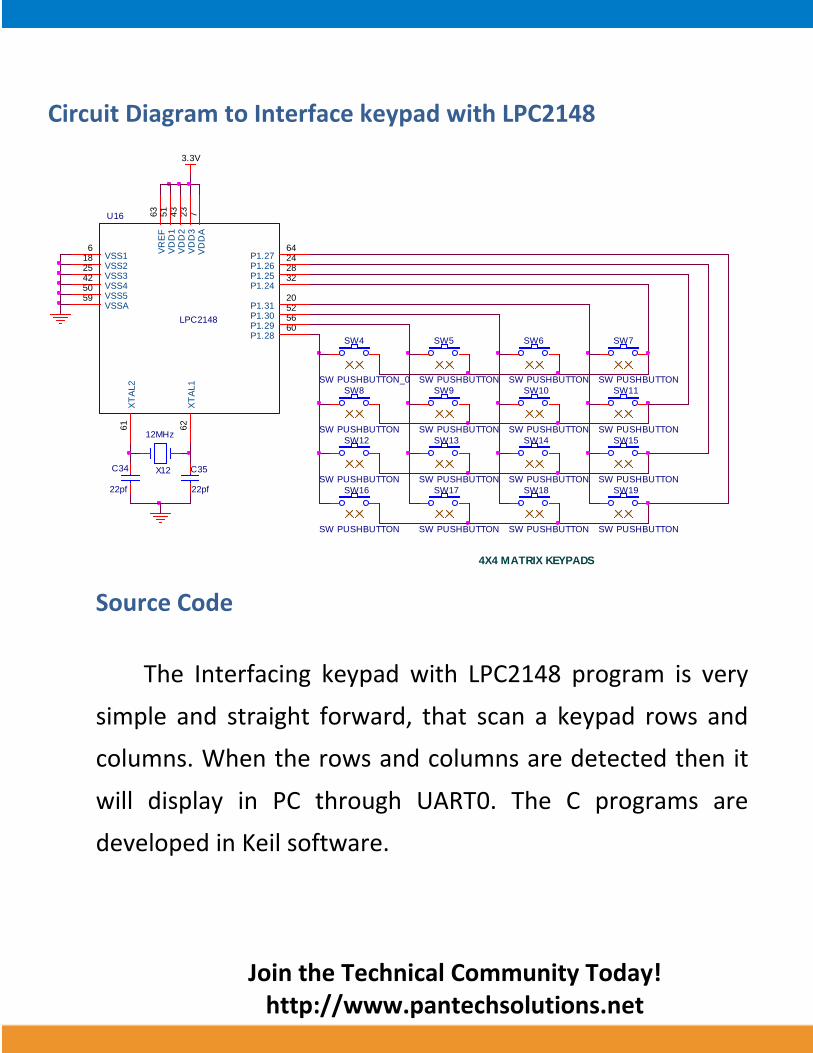
Circuit Diagram to Interface keypad with LPC2148
Source Code
The Interfacing keypad with LPC2148 program is very
simple and straight forward, that scan a keypad rows and
columns. When the rows and columns are detected then it
will display in PC through UART0. The C programs are
developed in Keil software.
C34
22pf
C35
22pf
3.3V
X12
12MHz
LPC2148
U16
VSS16 V
DD
A7
VSS218
VD
D3
23
VSS325
VD
D2
43
VSS442
VR
EF
63
XT
AL1
62
XT
AL2
61
VSSA59
VD
D1
51
VSS550 P1.24
32P1.2528P1.2624P1.2764
P1.2860P1.2956P1.3052P1.3120
SW5
SW PUSHBUTTON
SW6
SW PUSHBUTTON
SW7
SW PUSHBUTTON
SW9
SW PUSHBUTTON
SW8
SW PUSHBUTTON
SW10
SW PUSHBUTTON
SW11
SW PUSHBUTTON
SW12
SW PUSHBUTTON
SW13
SW PUSHBUTTON
SW14
SW PUSHBUTTON
SW15
SW PUSHBUTTON
SW17
SW PUSHBUTTON
SW16
SW PUSHBUTTON
SW18
SW PUSHBUTTON
SW19
SW PUSHBUTTON
4X4 MATRIX KEYPADS
SW4
SW PUSHBUTTON_0
Join the Technical Community Today!
http://www.pantechsolutions.net
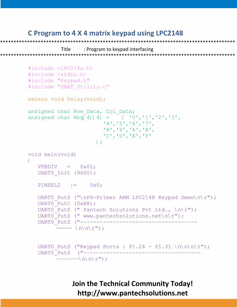
C Program to 4 X 4 matrix keypad using LPC2148 ***************************************************************************************
Title : Program to keypad interfacing ***************************************************************************************
#include <LPC214x.h>
#include <stdio.h>
#include "Keypad.h"
#include "UART_Utility.c"
extern void Delay(void);
unsigned char Row_Data, Col_Data;
unsigned char Msg[4][4] = { '0','1','2','3',
'4','5','6','7',
'8','9','A','B',
'C','D','E','F'
};
void main(void)
{
VPBDIV = 0x02;
UART0_Init (9600);
PINSEL2 |= 0x0;
UART0_PutS ("\nPS-Primer ARM LPC2148 Keypad Demo\n\r");
UART0_PutC (0xB8);
UART0_PutS (" Pantech Solutions Pvt Ltd., \n\r");
UART0_PutS (" www.pantechsolutions.net\n\r");
UART0_PutS ("------------------------------------
----- \n\n\r");
UART0_PutS ("Keypad Ports : P1.24 - P1.31 \n\n\n\r");
UART0_PutS ("~~~~~~~~~~~~~~~~~~~~~~~~~~~~~~~~~~~~
~~~~~~~\n\n\r");

Join the Technical Community Today!
http://www.pantechsolutions.net
while (1)
{
Delay();
Delay();
KeyScan(&IOPIN1,24,&Row_Data,&Col_Data);
UART0_PutS ("The Key You Pressed is : ");
if (Row_Data < 4 && Col_Data < 4)
{
U0THR = Msg[Row_Data][Col_Data];
Delay();
Delay();
U0THR = '\r';
}
}
}
void Delay(void)
{
unsigned int i,j;
for(i=0;i<35;i++)
for(j=0;j<1234;j++);
}
To compile the above C code you need the KEIL
software. They must be properly set up and a project with
correct settings must be created in order to compile the
code. To compile the above code, the C file must be added
to the project.

Join the Technical Community Today!
http://www.pantechsolutions.net
In Keil, you want to develop or debug the project
without any hardware setup. You must compile the code for
generating HEX file. In debugging Mode, you want to check
the port output without LPC2148 Primer Board.
The Flash Magic software is used to download the hex
file into your microcontroller IC LPC2148 through UART0.
Testing the Keypad with LPC2148
Give +3.3V power supply to LPC2148 Primer Board; the
serial cable is connected between the LPC2148 Primer
Board and PC. Open the Hyper Terminal screen, select
which port you are using and set the default settings. Now
the screen should show some text messages & it display
which key is pressed in keypad.
If you not reading any text from UART0, then you just
check the jumper connections & just check the serial cable
is working. And also check the keypad keys are properly
working or not. Otherwise you just check the code with
debugging mode in Keil.
Join the Technical Community Today!
http://www.pantechsolutions.net
If you want to see more details about debugging just
see the videos in below link.
How to Create & Debug a Project in Keil.
General Information
For proper working use the components of exact values
as shown in Circuit file. Wherever possible use new
components.
Solder everything in a clean way. A major problem
arises due to improper soldering, solder jumps and
loose joints.
Use the exact value crystal shown in schematic.
More instructions are available in following articles,
User Manual of LPC2148 Primer Board.
Tutorial of how to create & Debug a project in Keil.
Interfacing Switches with LPC2148.

Join the Technical Community Today!
http://www.pantechsolutions.net
Pantech solutions creates information packed technical
documents like this one every month. And our website is a rich
and trusted resource used by a vibrant online community of
more than 1,00,000 members from organization of all shapes
and sizes.
Did you enjoy the read?

Join the Technical Community Today!
http://www.pantechsolutions.net
What do we sell?
Our products range from Various Microcontroller
development boards, DSP Boards, FPGA/CPLD boards,
Communication Kits, Power electronics, Basic electronics,
Robotics, Sensors, Electronic components and much more . Our
goal is to make finding the parts and information you need
easier and affordable so you can create awesome projects and
training from Basic to Cutting edge technology.