Embed Size (px)
Citation preview

ARM HOW-TO GUIDE
Interfacing I2C-7SEG
with LPC2148 ARM

Join the Technical Community Today!
http://www.pantechsolutions.net
Contents at a Glance
ARM7 LPC2148 Primer Board ........................................... 3
I2C (Inter Integrated Circuit) ............................................ 3
Seven Segment Display .................................................... 4
Interfacing I2C - Seven Segment Display ........................... 4
Interfacing I2C – Seven Segment with LPC2148 ................ 6
Pin Assignment with LPC2148 .......................................... 6
Circuit Diagram to Interface I2C–7 seg with LPC2148 ........ 7
Source Code .................................................................... 7
C Program to I2C – 7 Segment Display using LPC2148 ....... 8
Testing the I2C – Seven segment with LPC2148 .............. 13
General Information ...................................................... 14

Join the Technical Community Today!
http://www.pantechsolutions.net
ARM7 LPC2148 Primer Board
The ARM7 LPC2148 Primer board is specifically
designed to help students to master the required skills in
the area of embedded systems. The kit is designed in such
way that all the possible features of the microcontroller will
be easily used by the students. The kit supports in system
programming (ISP) which is done through serial port.
NXP’s ARM7 (LPC2148), ARM Primer Kit is proposed to
smooth the progress of developing and debugging of
various designs encompassing of High speed 32-bit
Microcontrollers.
I2C (Inter Integrated Circuit)
The I2C (Inter-IC) bus is a bi-directional two-wire serial
bus that provides a communication link between integrated
circuits (ICs).I2C is a synchronous protocol that allows a
master device to initiate communication with a slave
device. Data is exchanged between these devices.

Join the Technical Community Today!
http://www.pantechsolutions.net
Seven Segment Display
A seven segment display is the most basic electronic
display device that can display digits from 0-9. The most
common configuration has an array of eight LEDs arranged
in a special pattern to display these digits. They are laid out
as a squared-off figure ‘8’. Every LED is assigned a name
from 'a' to 'h' and is identified by its name. Seven LEDs 'a' to
'g' are used to display the numerals while eighth LED 'h' is
used to display the dot/decimal.
Interfacing I2C - Seven Segment Display
Fig. 1 shows how to interface the seven segments with
microcontroller through I2C. I2C is a Master-Slave protocol.
I2C has a clock pulse along with the data. Normally, the
master device controls the clock line, SCL. This line dictates
the timing of all transfers on the I2C bus. No data will be
transferred unless the clock is manipulated. All slaves are
controlled by the same clock, SCL.

Join the Technical Community Today!
http://www.pantechsolutions.net
A seven segment is generally available in ten pin
package. While eight pins correspond to the eight LEDs, the
remaining two pins (at middle) are common and internally
shorted. These segments come in two configurations,
namely, Common cathode (CC) and Common anode (CA). In
CC configuration, the negative terminals of all LEDs are
connected to the common pins. The common is connected
to ground and a particular LED glows when its
corresponding pin is given high. In CA arrangement, the
common pin is given a high logic and the LED pins are given
low to display a number.
Fig. 1 Interfacing I2C - 7segment to Microcontroller

Join the Technical Community Today!
http://www.pantechsolutions.net
Interfacing I2C – Seven Segment with LPC2148
We now want to display a four digit number in LPC2148
Primer Board by using seven segment displays. The seven
segment display is connected with LPC2148 controller
through I2C.
In LPC2148 Primer Kit, 4 nos. of common anode seven
segment displays are controlled by I2C Enabled drivers. I2C
Lines serial clock SCL (P0.2), serial data SDA (P0.3)
connected to the I2C based 7-segment display driver. The
digit select lines are (MX1, MX2) controlled by the driver
chip. The 7-segmend display is powered from the 5V power
supply enabled by switch SW28.
Pin Assignment with LPC2148
7-S
EG D
isp
lay 7-SEG Driver LPC2148 LINES 7-SEG PWR Selection
SCL P0.2
SDA P0.3
Make switch SW28 to ‘7SEG’
label marking position
+5V
ONOFF
SW28
PWR ON/OFF
1234
8765
LCD7SEG
GLCDSM/RL

Join the Technical Community Today!
http://www.pantechsolutions.net
Circuit Diagram to Interface I2C–7 seg with LPC2148
Source Code
The Interfacing I2C – seven segment displays with
LPC2148 program is very simple and straight forward, that
display a four digit number in seven segment display by
using I2C.The C programs are developed in Keil software.
2_SEG22_SEG3
2_SEG0
2_SEG52_SEG4
2_SEG62_SEG7
U11
7 SEG DISP
E1 D2
CA
13
C4
DP5
B6 A7
CA
28
F9
G10
1_SEG11_SEG21_SEG3
1_SEG0
1_SEG51_SEG4
1_SEG61_SEG7
U8
7 SEG DISP
E1 D2
CA
13
C4
DP5
B6 A7
CA
28
F9
G10
U9
7 SEG DISP
E1 D2
CA
13
C4
DP5
B6 A7
CA
28
F9
G10
Q4BC847AL
23
1
1_SEG01_SEG11_SEG21_SEG3
C12 100n
U7
SAA1064
ADR1
CEXT2
P83
P74
P65
P56
P47
P38
P29
P110
MX111
VEE12
SCL24
SDA23
P1622
P1521
P1420
P1319
P1218
P1117
P1016
P915
MX214
VCC13
2_SEG72_SEG6
2_SEG42_SEG5
2_SEG22_SEG3
I2C 7-SEGMENT DISPLAY
2_SEG02_SEG1
R40
10k
R41
10k
3V3
C11
2.7nF
1_SEG41_SEG5
C36
22pf
C37
22pf
3.3V
X13
12MHz
LPC2148
U16
VSS16 V
DD
A7
VSS218
VD
D3
23
VSS325
VD
D2
43
VSS442
VR
EF
63
XT
AL1
62
XT
AL2
61
VSSA59
VD
D1
51
VSS550
P0.326
P0.222
1_SEG6
Q3BC847AL
23
1
2_SEG1
1_SEG7
2_SEG22_SEG3
2_SEG0
2_SEG52_SEG4
2_SEG62_SEG7
U10
7 SEG DISP
E1 D2
CA
13
C4
DP5
B6 A7
CA
28
F9
G10
2_SEG1

Join the Technical Community Today!
http://www.pantechsolutions.net
C Program to I2C – 7 Segment Display using LPC2148 ***************************************************************************************
Title : Program to I2C - Seven Segment display ***************************************************************************************
#include <LPC214x.h>
#include <stdio.h>
#define MAX 6
#define AA 2
#define SI 3
#define STO 4
#define STA 5
#define I2EN 6
void I2C_ISR(void)__irq;
void Wait (unsigned int);
void I2C_Init (void);
int I2C_Start (void);
int I2C_Write (unsigned char *Buff, unsigned int Count);
unsigned char Buff[] = {0x00,0x27,0x3F,0x06,0x5B,0x4F};
unsigned char index = 0;
void I2C_ISR(void)__irq
{
if (I2C0CONSET & 0x08)
{
switch (I2C0STAT)
{
case (0x08):
I2C0CONCLR = 1 << STA;
I2C0DAT = 0x70; //Slave Addr + W
break;

Join the Technical Community Today!
http://www.pantechsolutions.net
case (0x10):
I2C0CONCLR = 1 << STA; //Clear START Bit
I2C0DAT = 0x70;
break;
case (0x18):
I2C0CONCLR = 0x20; //Clear START Bit
I2C0DAT = Buff[index];
index++;
break;
case (0x20):
I2C0CONCLR = 0x20; //Clear START Bit
I2C0DAT = Buff[index];
index++;
break;
case (0x28):
I2C0CONCLR = 0x20; //Clear START Bit
if (index < MAX)
{
I2C0DAT = Buff[index];
index++;
}
else
{
index = 0;
I2C0CONSET = 0x10; //Send STOP Bit
}
break;

Join the Technical Community Today!
http://www.pantechsolutions.net
case (0x30):
I2C0CONCLR = 0x20; //Clear START Bit
if (index < MAX)
{
I2C0DAT = Buff[index];
index++;
}
else
{
index = 0;
I2C0CONSET = 0x10; //Send STOP Bit
I2C_Start();
}
break;
case (0x38):
I2C0CONSET = 0x20;
break;
}
}
I2C0CONCLR = 1 << SI;
VICVectAddr = 0x00;
}
void main()
{
unsigned int i;
VPBDIV = 0x02;
PINSEL0 = 0x00000055; // P0.3 - SDA0 & P0.2 - SCL0
U0LCR = 0x83;
U0DLL = 97;
U0DLM = 0x00;
U0LCR = 0x03;
Join the Technical Community Today!
http://www.pantechsolutions.net
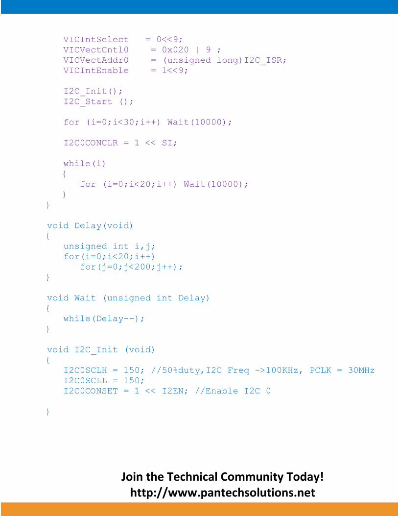
VICIntSelect = 0<<9;
VICVectCntl0 = 0x020 | 9 ;
VICVectAddr0 = (unsigned long)I2C_ISR;
VICIntEnable = 1<<9;
I2C_Init();
I2C_Start ();
for (i=0;i<30;i++) Wait(10000);
I2C0CONCLR = 1 << SI;
while(1)
{
for (i=0;i<20;i++) Wait(10000);
}
}
void Delay(void)
{
unsigned int i,j;
for(i=0;i<20;i++)
for(j=0;j<200;j++);
}
void Wait (unsigned int Delay)
{
while(Delay--);
}
void I2C_Init (void)
{
I2C0SCLH = 150; //50%duty,I2C Freq ->100KHz, PCLK = 30MHz
I2C0SCLL = 150;
I2C0CONSET = 1 << I2EN; //Enable I2C 0
}

Join the Technical Community Today!
http://www.pantechsolutions.net
int I2C_Start (void)
{
I2C0CONCLR = 1 << STO;
I2C0CONCLR = 1 << AA;
I2C0CONSET = 1 << STA;
return 0;
}
int I2C_Write (unsigned char *Buff, unsigned int Count)
{
while(Count--)
{
I2C0DAT = *Buff++;
}
return 0;
}
To compile the above C code you need the KEIL
software. They must be properly set up and a project with
correct settings must be created in order to compile the
code. To compile the above code, the C file must be added
to the project.
In Keil, you want to develop or debug the project
without any hardware setup. You must compile the code for
generating HEX file. In debugging Mode, you want to check
the port output without LPC2148 Primer Board.
The Flash Magic software is used to download the hex
file into your microcontroller IC LPC2148 through UART0.

Join the Technical Community Today!
http://www.pantechsolutions.net
Testing the I2C – Seven segment with LPC2148
Give +3.3V power supply to LPC2148 Primer Board; the
four seven segment display is connected with the LPC2148
Primer Board. First check the entire seven segments LED’s
are properly working or not.
Here we are display just 1234 in four seven segment.
The entire seven segments receive it through I2C & display
it in order.
If any data is not coming in seven segments, then you
just check the entire seven segments LED’s are working or
not. Change the seven segment driver IC & Check the I2C
connections. Check the four seven segments connections.
Otherwise you just check the code with debugging mode in
Keil. If you want to see more details about debugging just
see the videos in below link.
How to Create & Debug a Project in Keil.

Join the Technical Community Today!
http://www.pantechsolutions.net
General Information
For proper working use the components of exact values
as shown in Circuit file. Wherever possible use new
components.
Solder everything in a clean way. A major problem
arises due to improper soldering, solder jumps and
loose joints.
Use the exact value crystal shown in schematic.
More instructions are available in following articles,
Interfacing UART with LPC2148 Microcontroller.
Interfacing Keys with LPC2148 Microcontroller.
User Manual of LPC2148 Primer Board.
Tutorial of how to create & Debug a project in Keil.

Join the Technical Community Today!
http://www.pantechsolutions.net
Pantech solutions creates information packed technical
documents like this one every month. And our website is a rich
and trusted resource used by a vibrant online community of
more than 1,00,000 members from organization of all shapes
and sizes.
Did you enjoy the read?

Join the Technical Community Today!
http://www.pantechsolutions.net
What do we sell?
Our products range from Various Microcontroller
development boards, DSP Boards, FPGA/CPLD boards,
Communication Kits, Power electronics, Basic electronics,
Robotics, Sensors, Electronic components and much more . Our
goal is to make finding the parts and information you need
easier and affordable so you can create awesome projects and
training from Basic to Cutting edge technology.