Embed Size (px)
Citation preview
DAQNI-DAQ™ User Manualfor PC CompatiblesVersion 6.9Data Acquisition Software for the PC
NI-DAQ User Manual for PC Compatibles
October 2000 EditionPart Number 321644H-01

Worldwide Technical Support and Product Information
ni.com
National Instruments Corporate Headquarters
11500 North Mopac Expressway Austin, Texas 78759-3504 USA Tel: 512 794 0100
Worldwide Offices
Australia 03 9879 5166, Austria 0662 45 79 90 0, Belgium 02 757 00 20, Brazil 011 284 5011,Canada (Calgary) 403 274 9391, Canada (Ontario) 905 785 0085, Canada (Québec) 514 694 8521,China 0755 3904939, Denmark 45 76 26 00, Finland 09 725 725 11, France 01 48 14 24 24,Germany 089 741 31 30, Greece 30 1 42 96 427, Hong Kong 2645 3186, India 91805275406,Israel 03 6120092, Italy 02 413091, Japan 03 5472 2970, Korea 02 596 7456, Mexico (D.F.) 5 280 7625,Mexico (Monterrey) 8 357 7695, Netherlands 0348 433466, New Zealand 09 914 0488, Norway 32 27 73 00,Poland 0 22 528 94 06, Portugal 351 1 726 9011, Singapore 2265886, Spain 91 640 0085,Sweden 08 587 895 00, Switzerland 056 200 51 51, Taiwan 02 2528 7227, United Kingdom 01635 523545
For further support information, see the Technical Support Resources appendix. To comment on thedocumentation, send e-mail to [email protected]
© Copyright 1991, 2000 National Instruments Corporation. All rights reserved.
Important Information
WarrantyThe media on which you receive National Instruments software are warranted not to fail to execute programming instructions,due to defects in materials and workmanship, for a period of 90 days from date of shipment, as evidenced by receipts or otherdocumentation. National Instruments will, at its option, repair or replace software media that do not execute programminginstructions if National Instruments receives notice of such defects during the warranty period. National Instruments does notwarrant that the operation of the software shall be uninterrupted or error free.
A Return Material Authorization (RMA) number must be obtained from the factory and clearly marked on the outside ofthe package before any equipment will be accepted for warranty work. National Instruments will pay the shipping costs ofreturning to the owner parts which are covered by warranty.
National Instruments believes that the information in this document is accurate. The document has been carefully reviewedfor technical accuracy. In the event that technical or typographical errors exist, National Instruments reserves the right tomake changes to subsequent editions of this document without prior notice to holders of this edition. The reader should consultNational Instruments if errors are suspected. In no event shall National Instruments be liable for any damages arising out ofor related to this document or the information contained in it.
EXCEPT AS SPECIFIED HEREIN, NATIONAL INSTRUMENTS MAKES NO WARRANTIES, EXPRESS OR IMPLIED, AND SPECIFICALLY DISCLAIMS ANY
WARRANTY OF MERCHANTABILITY OR FITNESS FOR A PARTICULAR PURPOSE. CUSTOMER’S RIGHT TO RECOVER DAMAGES CAUSED BY FAULT OR
NEGLIGENCE ON THE PART OF NATIONAL INSTRUMENTS SHALL BE LIMITED TO THE AMOUNT THERETOFORE PAID BY THE CUSTOMER. NATIONAL
INSTRUMENTS WILL NOT BE LIABLE FOR DAMAGES RESULTING FROM LOSS OF DATA, PROFITS, USE OF PRODUCTS, OR INCIDENTAL OR
CONSEQUENTIAL DAMAGES, EVEN IF ADVISED OF THE POSSIBILITY THEREOF. This limitation of the liability of National Instruments willapply regardless of the form of action, whether in contract or tort, including negligence. Any action against National Instrumentsmust be brought within one year after the cause of action accrues. National Instruments shall not be liable for any delay inperformance due to causes beyond its reasonable control. The warranty provided herein does not cover damages, defects,malfunctions, or service failures caused by owner’s failure to follow the National Instruments installation, operation, ormaintenance instructions; owner’s modification of the product; owner’s abuse, misuse, or negligent acts; and power failure orsurges, fire, flood, accident, actions of third parties, or other events outside reasonable control.
CopyrightUnder the copyright laws, this publication may not be reproduced or transmitted in any form, electronic or mechanical, includingphotocopying, recording, storing in an information retrieval system, or translating, in whole or in part, without the prior writtenconsent of National Instruments Corporation.
TrademarksComponentWorks™, CVI™, DAQCard™, DAQ Designer™, DAQPad™, DAQ-PnP™, DAQ-STC™, LabVIEW™, NationalInstruments™, ni.com™, NI-DAQ™, PXI™, RTSI™, SCXI™, and VirtualBench™ are trademarks of National InstrumentsCorporation.
Product and company names mentioned herein are trademarks or trade names of their respective companies.
WARNING REGARDING USE OF NATIONAL INSTRUMENTS PRODUCTS(1) NATIONAL INSTRUMENTS PRODUCTS ARE NOT DESIGNED WITH COMPONENTS AND TESTING FOR A LEVELOF RELIABILITY SUITABLE FOR USE IN OR IN CONNECTION WITH SURGICAL IMPLANTS OR AS CRITICALCOMPONENTS IN ANY LIFE SUPPORT SYSTEMS WHOSE FAILURE TO PERFORM CAN REASONABLY BEEXPECTED TO CAUSE SIGNIFICANT INJURY TO A HUMAN.
(2) IN ANY APPLICATION, INCLUDING THE ABOVE, RELIABILITY OF OPERATION OF THE SOFTWARE PRODUCTSCAN BE IMPAIRED BY ADVERSE FACTORS, INCLUDING BUT NOT LIMITED TO FLUCTUATIONS IN ELECTRICALPOWER SUPPLY, COMPUTER HARDWARE MALFUNCTIONS, COMPUTER OPERATING SYSTEM SOFTWAREFITNESS, FITNESS OF COMPILERS AND DEVELOPMENT SOFTWARE USED TO DEVELOP AN APPLICATION,INSTALLATION ERRORS, SOFTWARE AND HARDWARE COMPATIBILITY PROBLEMS, MALFUNCTIONS ORFAILURES OF ELECTRONIC MONITORING OR CONTROL DEVICES, TRANSIENT FAILURES OF ELECTRONICSYSTEMS (HARDWARE AND/OR SOFTWARE), UNANTICIPATED USES OR MISUSES, OR ERRORS ON THE PART OFTHE USER OR APPLICATIONS DESIGNER (ADVERSE FACTORS SUCH AS THESE ARE HEREAFTERCOLLECTIVELY TERMED “SYSTEM FAILURES”). ANY APPLICATION WHERE A SYSTEM FAILURE WOULDCREATE A RISK OF HARM TO PROPERTY OR PERSONS (INCLUDING THE RISK OF BODILY INJURY AND DEATH)SHOULD NOT BE RELIANT SOLELY UPON ONE FORM OF ELECTRONIC SYSTEM DUE TO THE RISK OF SYSTEMFAILURE. TO AVOID DAMAGE, INJURY, OR DEATH, THE USER OR APPLICATION DESIGNER MUST TAKEREASONABLY PRUDENT STEPS TO PROTECT AGAINST SYSTEM FAILURES, INCLUDING BUT NOT LIMITED TOBACK-UP OR SHUT DOWN MECHANISMS. BECAUSE EACH END-USER SYSTEM IS CUSTOMIZED AND DIFFERSFROM NATIONAL INSTRUMENTS' TESTING PLATFORMS AND BECAUSE A USER OR APPLICATION DESIGNERMAY USE NATIONAL INSTRUMENTS PRODUCTS IN COMBINATION WITH OTHER PRODUCTS IN A MANNER NOTEVALUATED OR CONTEMPLATED BY NATIONAL INSTRUMENTS, THE USER OR APPLICATION DESIGNER ISULTIMATELY RESPONSIBLE FOR VERIFYING AND VALIDATING THE SUITABILITY OF NATIONALINSTRUMENTS PRODUCTS WHENEVER NATIONAL INSTRUMENTS PRODUCTS ARE INCORPORATED IN ASYSTEM OR APPLICATION, INCLUDING, WITHOUT LIMITATION, THE APPROPRIATE DESIGN, PROCESS ANDSAFETY LEVEL OF SUCH SYSTEM OR APPLICATION.
© National Instruments Corporation v NI-DAQ User Manual for PC Compatibles
Contents
About This ManualHow to Use the NI-DAQ Documentation Set ...............................................................xiConventions Used in This Manual.................................................................................xi
MIO and AI Device Terminology ...................................................................xv
Chapter 1Introduction to NI-DAQ
About the NI-DAQ Software for PC Compatibles ........................................................1-1How to Set Up Your DAQ System................................................................................1-2NI-DAQ Overview ........................................................................................................1-3
NI-DAQ Hardware Support ............................................................................1-4NI-DAQ Language Support ............................................................................1-7
Device Configuration.....................................................................................................1-7Using Measurement & Automation Explorer..................................................1-7
Chapter 2Fundamentals of Building Windows Applications
The NI-DAQ Libraries...................................................................................................2-1Creating a Windows Application Using Microsoft Visual C++....................................2-2
Developing an NI-DAQ Application...............................................................2-2Example Programs...........................................................................................2-2Special Considerations ....................................................................................2-3
Buffer Allocation ..............................................................................2-3String Passing....................................................................................2-3Parameter Passing .............................................................................2-3
Creating a Windows Application Using Microsoft Visual Basic ..................................2-4Developing an NI-DAQ Application...............................................................2-4Example Programs...........................................................................................2-5Special Considerations ....................................................................................2-5
Buffer Allocation ..............................................................................2-5String Passing....................................................................................2-6Parameter Passing .............................................................................2-6
Creating a Windows Application Using Borland C++ ..................................................2-7Developing an NI-DAQ Application...............................................................2-7Example Programs...........................................................................................2-7Special Considerations ....................................................................................2-8
Using Borland Delphi with NI-DAQ.............................................................................2-8NI-DAQ Examples ........................................................................................................2-9
Contents
NI-DAQ User Manual for PC Compatibles vi ni.com
Chapter 3Software Overview
Initialization and General-Configuration Functions...................................................... 3-2Software-Calibration and Device-Specific Functions ................................................... 3-3Event Message Functions .............................................................................................. 3-5
Event Messaging Application Tips ................................................................. 3-5NI-DAQ Events in Visual Basic for Windows ............................................... 3-6
ActiveX Controls for Visual Basic ................................................... 3-6General DAQ Event.......................................................................... 3-7Analog Trigger Event ....................................................................... 3-9Analog Alarm Event ......................................................................... 3-11
Analog Input Function Group ....................................................................................... 3-15One-Shot Analog Input Functions .................................................................. 3-16
Single-Channel Analog Input Functions .......................................... 3-16Data Acquisition Functions............................................................................. 3-20
High-Level Data Acquisition Functions........................................... 3-20Low-Level Data Acquisition Functions ........................................... 3-21Low-Level Double-Buffered Data Acquisition Functions ............... 3-23Data Acquisition Application Tips ................................................... 3-24Multirate Scanning ........................................................................... 3-32
Analog Output Function Group..................................................................................... 3-35One-Shot Analog Output Functions................................................................ 3-35
Analog Output Application Tips ...................................................... 3-36Waveform Generation Functions .................................................................... 3-39
High-Level Waveform Generation Functions .................................. 3-39Low-Level Waveform Generation Functions................................... 3-39Waveform Generation Application Tips .......................................... 3-41
Digital I/O Function Group ........................................................................................... 3-52DIO-24, 6025E, AT-MIO-16DE-10, DIO-96,
and Lab and 1200 Device Groups ................................................................ 3-55DIO-32F and 653X Device Groups................................................................. 3-55PCI-6115 and PCI-6120 Device Groups......................................................... 3-56Digital I/O Functions ...................................................................................... 3-57Group Digital I/O Functions ........................................................................... 3-58Double-Buffered Digital I/O Functions .......................................................... 3-59Digital Change Notification Functions ........................................................... 3-60Digital Filtering Function................................................................................ 3-60
Digital Change Notification Applications with 652X Devices......... 3-60Digital Change Detection Applications with 653X Devices ............ 3-61
Contents
© National Instruments Corporation vii NI-DAQ User Manual for PC Compatibles
Digital I/O Application Tips............................................................................3-62Handshaking Versus No-Handshaking Digital I/O...........................3-63Digital Port I/O Applications ............................................................3-63
Digital Line I/O Applications..........................................................................3-65Digital Group I/O Applications .......................................................................3-67Digital Group Block I/O Applications ............................................................3-69Digital Double-Buffered Group Block I/O Applications ................................3-71Pattern Generation I/O with the DIO-32F, 653X,
PCI-6115, and PCI-6120 Devices ................................................................3-74Double-Buffered I/O .......................................................................................3-75
Counter/Timer Function Group .....................................................................................3-76Counter/Timer Functions.................................................................................3-77
Counter/Timer Operation for the CTR Functions.............................3-78Programmable Frequency Output Operation ....................................3-81Counter/Timer Application Tips.......................................................3-82
Interval Counter/Timer Functions ...................................................................3-91Interval Counter/Timer Operation for the ICTR Functions ..............3-92Interval Counter/Timer Application Tips .........................................3-92
General-Purpose Counter/Timer Functions.....................................................3-93General-Purpose Counter/Timer Application Tips ...........................3-94
Clocks or Time Counters.................................................................................3-95Clock Resolution...............................................................................3-95Clock Synchronization......................................................................3-96Clock Accuracy.................................................................................3-98Example Clock in a Measurement System .......................................3-98Sample Use Cases .............................................................................3-99
RTSI Bus Trigger Functions ...........................................................................3-102RTSI Bus .........................................................................................................3-102E Series, DSA, 660X, and 671X RTSI Connections........................................3-103AT-AO-6/10 RTSI Connections......................................................................3-104DIO-32F RTSI Connections............................................................................3-104653X RTSI Connections ..................................................................................3-105RTSI Bus Application Tips .............................................................................3-106
SCXI Functions..............................................................................................................3-107SCXI Application Tips ....................................................................................3-112
Building Analog Input Applications in Multiplexed Mode ..............3-113Building Analog Input Applications in Parallel Mode .....................3-120SCXI Data Acquisition Rates ...........................................................3-124
Analog Output Applications............................................................................3-126Digital Applications.........................................................................................3-127
Contents
NI-DAQ User Manual for PC Compatibles viii ni.com
Chapter 4NI-DAQ Double Buffering
Overview ....................................................................................................................... 4-1Single-Buffered Versus Double-Buffered Data ............................................................ 4-1Double-Buffered Input Operations................................................................................ 4-2
Potential Setbacks ........................................................................................... 4-4Double-Buffered Output Operations ............................................................................. 4-6
Potential Setbacks ........................................................................................... 4-7Double-Buffered Functions ........................................................................................... 4-9
Double Buffer Configuration Functions ......................................................... 4-10Double Buffer Transfer Functions .................................................................. 4-10Double Buffer HalfReady Functions .............................................................. 4-11
Conclusion..................................................................................................................... 4-12
Chapter 5Transducer Conversion Functions
Function Descriptions.................................................................................................... 5-2RTD_Convert and RTD_Buf_Convert ........................................................... 5-2
Parameter Discussion ....................................................................... 5-2Using This Function ......................................................................... 5-3
Strain_Convert and Strain_Buf_Convert ........................................................ 5-4Parameter Discussion ....................................................................... 5-4Using This Function ......................................................................... 5-5
Thermistor_Convert and Thermistor_Buf_Convert........................................ 5-7Parameter Discussion ....................................................................... 5-7Using This Function ......................................................................... 5-8
Thermocouple_Convert and Thermocouple_Buf_Convert ............................ 5-9Parameter Discussion ....................................................................... 5-9Using This Function ......................................................................... 5-10
Appendix ATechnical Support Resources
Glossary
Index
© National Instruments Corporation ix NI-DAQ User Manual for PC Compatibles
About This Manual
The NI-DAQ User Manual for PC Compatibles is for users of the NI-DAQsoftware for PC compatibles version 6.9. NI-DAQ software is a powerfulapplication programming interface (API) between your data acquisition(DAQ) application and the National Instruments DAQ devices. Source codefor several example applications is included in this manual.
How to Use the NI-DAQ Documentation SetBegin by reading the NI-DAQ release notes and this manual. Chapter 1,Introduction to NI-DAQ, contains a flowchart that illustrates how to set upyour DAQ system using either NI-DAQ or other National Instrumentsapplication software.
When you are familiar with the material in this manual, you can begin touse the NI-DAQ Function Reference Online Help file, Nidaqpc.hlp, theWindows help file that contains detailed descriptions of the NI-DAQfunctions. Other documentation includes the DAQ Hardware OverviewGuide, and the DAQ provider help contained in Measurement &Automation Explorer.
For detailed hardware information, refer to the user manual included witheach device.
Conventions Used in This ManualThe following conventions are used in this manual.
» The » symbol leads you through nested menu items and dialog box optionsto a final action. The sequence File»Page Setup»Options directs you topull down the File menu, select the Page Setup item, and select Optionsfrom the last dialog box.
This icon denotes a note, which alerts you to important information.
1102/B/C modules Refers to the SCXI-1102, SCXI-1102B, and SCXI-1102C modules and theVXI-SC-1102, VXI-SC-1102B, and VXI-SC-1102C submodules.
12-bit device These MIO and AI devices are listed in Table 1.
About This Manual
NI-DAQ User Manual for PC Compatibles x ni.com
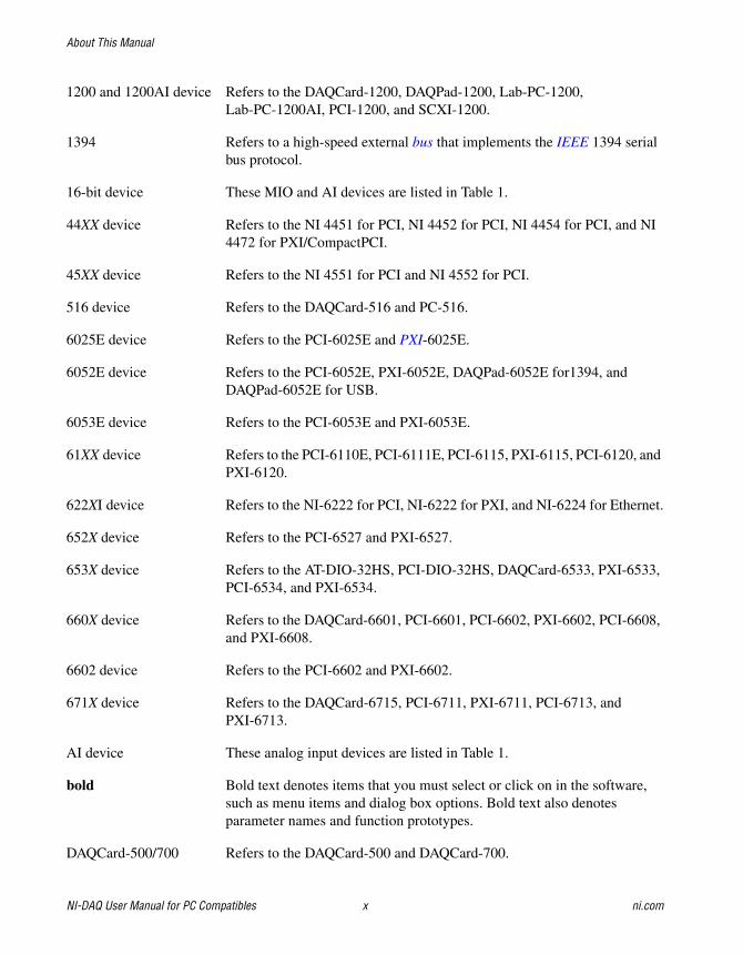
1200 and 1200AI device Refers to the DAQCard-1200, DAQPad-1200, Lab-PC-1200,Lab-PC-1200AI, PCI-1200, and SCXI-1200.
1394 Refers to a high-speed external bus that implements the IEEE 1394 serialbus protocol.
16-bit device These MIO and AI devices are listed in Table 1.
44XX device Refers to the NI 4451 for PCI, NI 4452 for PCI, NI 4454 for PCI, and NI4472 for PXI/CompactPCI.
45XX device Refers to the NI 4551 for PCI and NI 4552 for PCI.
516 device Refers to the DAQCard-516 and PC-516.
6025E device Refers to the PCI-6025E and PXI-6025E.
6052E device Refers to the PCI-6052E, PXI-6052E, DAQPad-6052E for1394, andDAQPad-6052E for USB.
6053E device Refers to the PCI-6053E and PXI-6053E.
61XX device Refers to the PCI-6110E, PCI-6111E, PCI-6115, PXI-6115, PCI-6120, andPXI-6120.
622XI device Refers to the NI-6222 for PCI, NI-6222 for PXI, and NI-6224 for Ethernet.
652X device Refers to the PCI-6527 and PXI-6527.
653X device Refers to the AT-DIO-32HS, PCI-DIO-32HS, DAQCard-6533, PXI-6533,PCI-6534, and PXI-6534.
660X device Refers to the DAQCard-6601, PCI-6601, PCI-6602, PXI-6602, PCI-6608,and PXI-6608.
6602 device Refers to the PCI-6602 and PXI-6602.
671X device Refers to the DAQCard-6715, PCI-6711, PXI-6711, PCI-6713, andPXI-6713.
AI device These analog input devices are listed in Table 1.
bold Bold text denotes items that you must select or click on in the software,such as menu items and dialog box options. Bold text also denotesparameter names and function prototypes.
DAQCard-500/700 Refers to the DAQCard-500 and DAQCard-700.
About This Manual
© National Instruments Corporation xi NI-DAQ User Manual for PC Compatibles
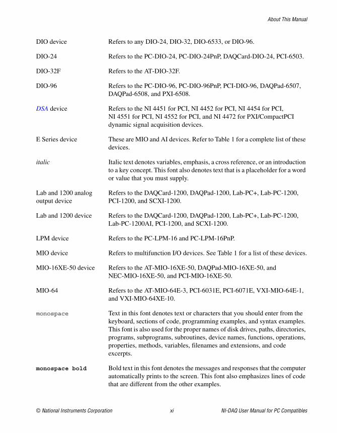
DIO device Refers to any DIO-24, DIO-32, DIO-6533, or DIO-96.
DIO-24 Refers to the PC-DIO-24, PC-DIO-24PnP, DAQCard-DIO-24, PCI-6503.
DIO-32F Refers to the AT-DIO-32F.
DIO-96 Refers to the PC-DIO-96, PC-DIO-96PnP, PCI-DIO-96, DAQPad-6507,DAQPad-6508, and PXI-6508.
DSA device Refers to the NI 4451 for PCI, NI 4452 for PCI, NI 4454 for PCI,NI 4551 for PCI, NI 4552 for PCI, and NI 4472 for PXI/CompactPCIdynamic signal acquisition devices.
E Series device These are MIO and AI devices. Refer to Table 1 for a complete list of thesedevices.
italic Italic text denotes variables, emphasis, a cross reference, or an introductionto a key concept. This font also denotes text that is a placeholder for a wordor value that you must supply.
Lab and 1200 analog Refers to the DAQCard-1200, DAQPad-1200, Lab-PC+, Lab-PC-1200,output device PCI-1200, and SCXI-1200.
Lab and 1200 device Refers to the DAQCard-1200, DAQPad-1200, Lab-PC+, Lab-PC-1200,Lab-PC-1200AI, PCI-1200, and SCXI-1200.
LPM device Refers to the PC-LPM-16 and PC-LPM-16PnP.
MIO device Refers to multifunction I/O devices. See Table 1 for a list of these devices.
MIO-16XE-50 device Refers to the AT-MIO-16XE-50, DAQPad-MIO-16XE-50, andNEC-MIO-16XE-50, and PCI-MIO-16XE-50.
MIO-64 Refers to the AT-MIO-64E-3, PCI-6031E, PCI-6071E, VXI-MIO-64E-1,and VXI-MIO-64XE-10.
monospace Text in this font denotes text or characters that you should enter from thekeyboard, sections of code, programming examples, and syntax examples.This font is also used for the proper names of disk drives, paths, directories,programs, subprograms, subroutines, device names, functions, operations,properties, methods, variables, filenames and extensions, and codeexcerpts.
monospace bold Bold text in this font denotes the messages and responses that the computerautomatically prints to the screen. This font also emphasizes lines of codethat are different from the other examples.
About This Manual
NI-DAQ User Manual for PC Compatibles xii ni.com
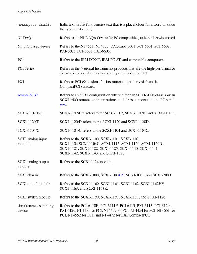
monospace italic Italic text in this font denotes text that is a placeholder for a word or valuethat you must supply.
NI-DAQ Refers to the NI-DAQ software for PC compatibles, unless otherwise noted.
NI-TIO based device Refers to the NI 4551, NI 4552, DAQCard-6601, PCI-6601, PCI-6602,PXI-6602, PCI-6608, PXI-6608.
PC Refers to the IBM PC/XT, IBM PC AT, and compatible computers.
PCI Series Refers to the National Instruments products that use the high-performanceexpansion bus architecture originally developed by Intel.
PXI Refers to PCI eXtensions for Instrumentation, derived from theCompactPCI standard.
remote SCXI Refers to an SCXI configuration where either an SCXI-2000 chassis or anSCXI-2400 remote communications module is connected to the PC serialport.
SCXI-1102/B/C SCXI-1102/B/C refers to the SCXI-1102, SCXI-1102B, and SCXI-1102C.
SCXI-1120/D SCXI-1120/D refers to the SCXI-1120 and SCXI-1120D.
SCXI-1104/C SCXI-1104/C refers to the SCXI-1104 and SCXI-1104C.
SCXI analog input Refers to the SCXI-1100, SCXI-1101, SCXI-1102,module SCXI-1104,SCXI-1104C, SCXI-1112, SCXI-1120, SCXI-1120D,
SCXI-1121, SCXI-1122, SCXI-1125, SCXI-1140, SCXI-1141,SCXI-1142, SCXI-1143, and SCXI-1520.
SCXI analog output Refers to the SCXI-1124 module.module
SCXI chassis Refers to the SCXI-1000, SCXI-1000DC, SCXI-1001, and SCXI-2000.
SCXI digital module Refers to the SCXI-1160, SCXI-1161, SCXI-1162, SCXI-1162HV,SCXI-1163, and SCXI-1163R.
SCXI switch module Refers to the SCXI-1190, SCXI-1191, SCXI-1127, and SCXI-1128.
simultaneous sampling Refers to the PCI-6110E, PCI-6111E, PCI-6115, PXI-6115, PCI-6120,device PXI-6120, NI 4451 for PCI, NI 4452 for PCI, NI 4454 for PCI, NI 4551 for
PCI, NI 4552 for PCI, and NI 4472 for PXI/CompactPCI.
About This Manual
© National Instruments Corporation xiii NI-DAQ User Manual for PC Compatibles
track-and-hold Refers to the SCXI-1140, SCXI-1520, SCXI-1530, and SCXI-1531.module
VXI-MIO device Refers to the VXI-MIO-64E-1 and VXI-MIO-64XE-10.
VXI-SC-1102/B/C Refers to the VXI-SC-1102, VXI-SC-1102B, and VXI-SC-1102C.
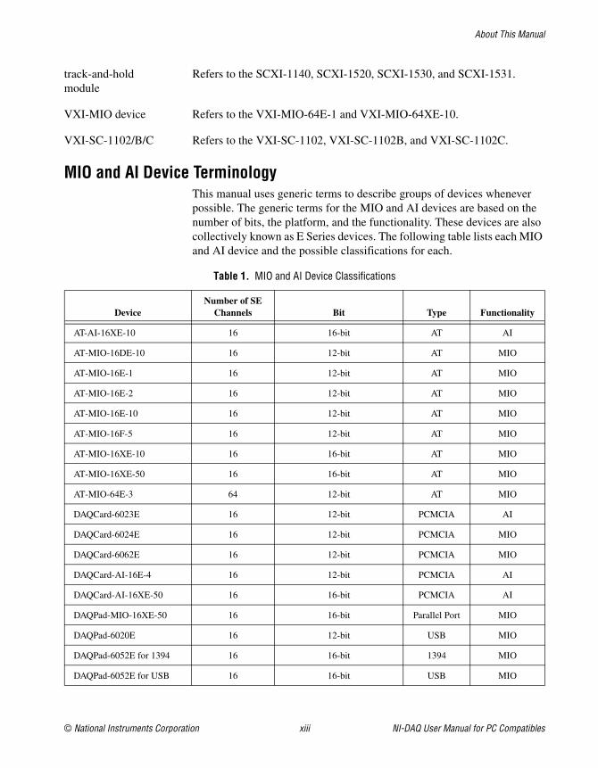
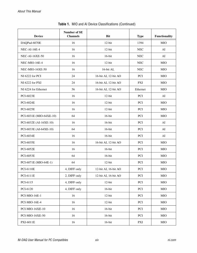
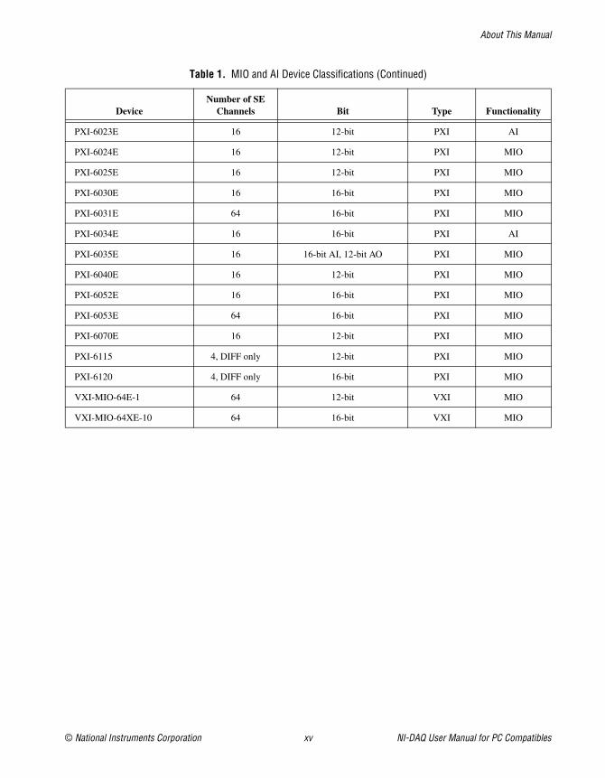
MIO and AI Device TerminologyThis manual uses generic terms to describe groups of devices wheneverpossible. The generic terms for the MIO and AI devices are based on thenumber of bits, the platform, and the functionality. These devices are alsocollectively known as E Series devices. The following table lists each MIOand AI device and the possible classifications for each.
Table 1. MIO and AI Device Classifications
DeviceNumber of SE
Channels Bit Type Functionality
AT-AI-16XE-10 16 16-bit AT AI
AT-MIO-16DE-10 16 12-bit AT MIO
AT-MIO-16E-1 16 12-bit AT MIO
AT-MIO-16E-2 16 12-bit AT MIO
AT-MIO-16E-10 16 12-bit AT MIO
AT-MIO-16F-5 16 12-bit AT MIO
AT-MIO-16XE-10 16 16-bit AT MIO
AT-MIO-16XE-50 16 16-bit AT MIO
AT-MIO-64E-3 64 12-bit AT MIO
DAQCard-6023E 16 12-bit PCMCIA AI
DAQCard-6024E 16 12-bit PCMCIA MIO
DAQCard-6062E 16 12-bit PCMCIA MIO
DAQCard-AI-16E-4 16 12-bit PCMCIA AI
DAQCard-AI-16XE-50 16 16-bit PCMCIA AI
DAQPad-MIO-16XE-50 16 16-bit Parallel Port MIO
DAQPad-6020E 16 12-bit USB MIO
DAQPad-6052E for 1394 16 16-bit 1394 MIO
DAQPad-6052E for USB 16 16-bit USB MIO
About This Manual
NI-DAQ User Manual for PC Compatibles xiv ni.com
DAQPad-6070E 16 12-bit 1394 MIO
NEC-AI-16E-4 16 12-bit NEC AI
NEC-AI-16XE-50 16 16-bit NEC AI
NEC-MIO-16E-4 16 12-bit NEC MIO
NEC-MIO-16XE-50 16 16-bit AI, NEC MIO
NI 6222 for PCI 24 16-bit AI, 12-bit AO PCI MIO
NI 6222 for PXI 24 16-bit AI, 12-bit AO PXI MIO
NI 6224 for Ethernet 56 16-bit AI, 12-bit AO Ethernet MIO
PCI-6023E 16 12-bit PCI AI
PCI-6024E 16 12-bit PCI MIO
PCI-6025E 16 12-bit PCI MIO
PCI-6031E (MIO-64XE-10) 64 16-bit PCI MIO
PCI-6032E (AI-16XE-10) 16 16-bit PCI AI
PCI-6033E (AI-64XE-10) 64 16-bit PCI AI
PCI-6034E 16 16-bit PCI AI
PCI-6035E 16 16-bit AI, 12-bit AO PCI MIO
PCI-6052E 16 16-bit PCI MIO
PCI-6053E 64 16-bit PCI MIO
PCI-6071E (MIO-64E-1) 64 12-bit PCI MIO
PCI-6110E 4, DIFF only 12-bit AI, 16-bit AO PCI MIO
PCI-6111E 2, DIFF only 12-bit AI, 16-bit AO PCI MIO
PCI-6115 4, DIFF only 12-bit PCI MIO
PCI-6120 4, DIFF only 16-bit PCI MIO
PCI-MIO-16E-1 16 12-bit PCI MIO
PCI-MIO-16E-4 16 12-bit PCI MIO
PCI-MIO-16XE-10 16 16-bit PCI MIO
PCI-MIO-16XE-50 16 16-bit PCI MIO
PXI-6011E 16 16-bit PXI MIO
Table 1. MIO and AI Device Classifications (Continued)
DeviceNumber of SE
Channels Bit Type Functionality
About This Manual
© National Instruments Corporation xv NI-DAQ User Manual for PC Compatibles
PXI-6023E 16 12-bit PXI AI
PXI-6024E 16 12-bit PXI MIO
PXI-6025E 16 12-bit PXI MIO
PXI-6030E 16 16-bit PXI MIO
PXI-6031E 64 16-bit PXI MIO
PXI-6034E 16 16-bit PXI AI
PXI-6035E 16 16-bit AI, 12-bit AO PXI MIO
PXI-6040E 16 12-bit PXI MIO
PXI-6052E 16 16-bit PXI MIO
PXI-6053E 64 16-bit PXI MIO
PXI-6070E 16 12-bit PXI MIO
PXI-6115 4, DIFF only 12-bit PXI MIO
PXI-6120 4, DIFF only 16-bit PXI MIO
VXI-MIO-64E-1 64 12-bit VXI MIO
VXI-MIO-64XE-10 64 16-bit VXI MIO
Table 1. MIO and AI Device Classifications (Continued)
DeviceNumber of SE
Channels Bit Type Functionality
© National Instruments Corporation 1-1 NI-DAQ User Manual for PC Compatibles
1Introduction to NI-DAQ
This chapter describes how to set up your DAQ system and configure yourDAQ devices.
About the NI-DAQ Software for PC CompatiblesThank you for buying a National Instruments DAQ device, which includesNI-DAQ software for PC compatibles. NI-DAQ is a set of functions thatcontrol all of the National Instruments plug-in DAQ devices for analog I/O,digital I/O, timing I/O, SCXI signal conditioning, and RTSI multiboardsynchronization.
NI-DAQ has both high-level DAQ I/O functions for maximum easeof use, and low-level DAQ I/O functions for maximum flexibility andperformance. Examples of high-level functions are streaming data todisk or acquiring a certain number of data points. Examples of low-levelfunctions are writing directly to the DAQ device registers or calibratingthe analog inputs. NI-DAQ does not sacrifice the performance ofNational Instruments DAQ devices because it lets multiple devicesoperate at their peak performance.
NI-DAQ includes a Buffer and Data Manager that uses sophisticatedtechniques for handling and managing data acquisition buffers so that youcan acquire and process data simultaneously. NI-DAQ can transfer datausing DMA, interrupts, or software polling. NI-DAQ can use DMA totransfer data into memory above 16 MB even on ISA bus computers.
With the NI-DAQ Resource Manager, you can use several functionsand several devices simultaneously. The Resource Manager preventsmultiboard contention over DMA channels, interrupt levels, andRTSI channels.
Chapter 1 Introduction to NI-DAQ
NI-DAQ User Manual for PC Compatibles 1-2 ni.com
NI-DAQ can send event-driven messages to Windows or Windows NTapplications each time a user-specified event occurs. Thus, polling iseliminated and you can develop event-driven DAQ applications. Someexamples of NI-DAQ user events are:
• When a specified number of analog samples has been acquired
• When the analog level and slope of a signal match specified levels
• When the signal is inside or outside a voltage band
• When a specified digital I/O pattern is matched
• When a rising or falling edge occurred on a timing I/O line
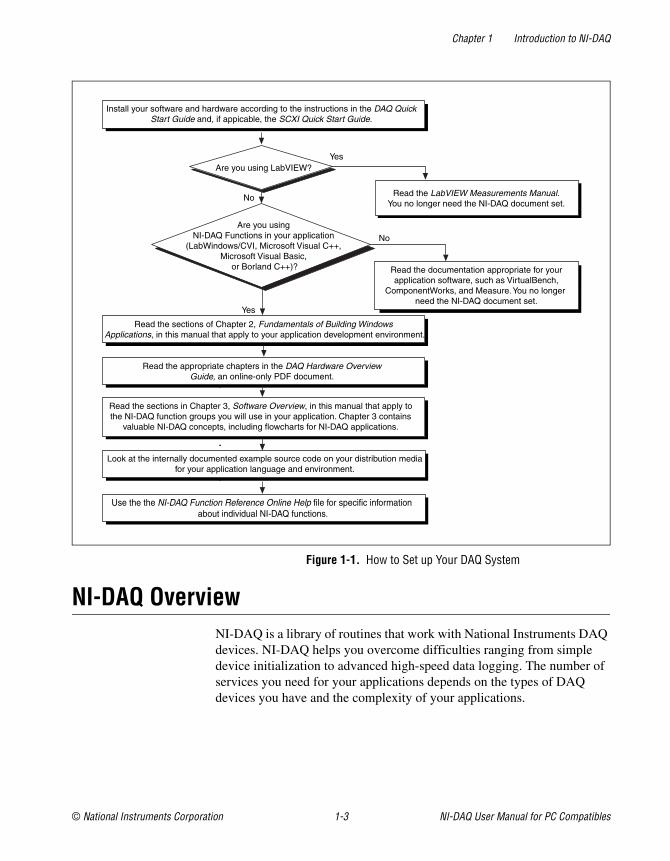
How to Set Up Your DAQ SystemAfter you have installed your software and hardware and configured yourhardware, see Figure 1-1 to begin using NI-DAQ in your applicationprograms.
If you are accessing the NI-DAQ device drivers through LabVIEW, readthe NI-DAQ release notes and then use your LabVIEW Online Reference tohelp you get started using the data acquisition VIs in LabVIEW.
Chapter 1 Introduction to NI-DAQ
© National Instruments Corporation 1-3 NI-DAQ User Manual for PC Compatibles
Figure 1-1. How to Set up Your DAQ System
NI-DAQ OverviewNI-DAQ is a library of routines that work with National Instruments DAQdevices. NI-DAQ helps you overcome difficulties ranging from simpledevice initialization to advanced high-speed data logging. The number ofservices you need for your applications depends on the types of DAQdevices you have and the complexity of your applications.
No
No
YesAre you using LabVIEW?
Read the sections of Chapter 2, Fundamentals of Building WindowsApplications, in this manual that apply to your application development environment.
Read the appropriate chapters in the DAQ Hardware OverviewGuide, an online-only PDF document.
Read the sections in Chapter 3, Software Overview, in this manual that apply tothe NI-DAQ function groups you will use in your application. Chapter 3 contains
valuable NI-DAQ concepts, including flowcharts for NI-DAQ applications.
Read the LabVIEW Measurements Manual.You no longer need the NI-DAQ document set.
Look at the internally documented example source code on your distribution mediafor your application language and environment.
Use the the NI-DAQ Function Reference Online Help file for specific information about individual NI-DAQ functions.
Are you usingNI-DAQ Functions in your application
(LabWindows/CVI, Microsoft Visual C++,Microsoft Visual Basic,
or Borland C++)?
Yes
Read the documentation appropriate for yourapplication software, such as VirtualBench,
ComponentWorks, and Measure. You no longer need the NI-DAQ document set.
Install your software and hardware according to the instructions in the DAQ QuickStart Guide and, if appicable, the SCXI Quick Start Guide.
Chapter 1 Introduction to NI-DAQ
NI-DAQ User Manual for PC Compatibles 1-4 ni.com
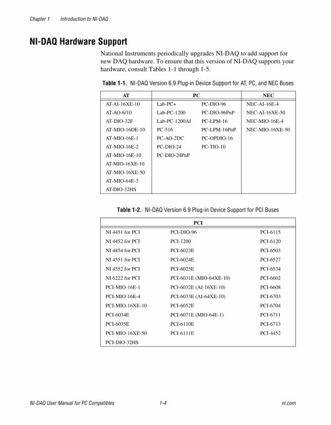
NI-DAQ Hardware SupportNational Instruments periodically upgrades NI-DAQ to add support fornew DAQ hardware. To ensure that this version of NI-DAQ supports yourhardware, consult Tables 1-1 through 1-5.
.Table 1-1. NI-DAQ Version 6.9 Plug-in Device Support for AT, PC, and NEC Buses
AT PC NEC
AT-AI-16XE-10 Lab-PC+ PC-DIO-96 NEC-AI-16E-4
AT-AO-6/10 Lab-PC-1200 PC-DIO-96PnP NEC-AI-16XE-50
AT-DIO-32F Lab-PC-1200AI PC-LPM-16 NEC-MIO-16E-4
AT-MIO-16DE-10 PC-516 PC-LPM-16PnP NEC-MIO-16XE-50
AT-MIO-16E-1 PC-AO-2DC PC-OPDIO-16
AT-MIO-16E-2 PC-DIO-24 PC-TIO-10
AT-MIO-16E-10 PC-DIO-24PnP
AT-MIO-16XE-10
AT-MIO-16XE-50
AT-MIO-64E-3
AT-DIO-32HS
Table 1-2. NI-DAQ Version 6.9 Plug-in Device Support for PCI Buses
PCI
NI 4451 for PCI PCI-DIO-96 PCI-6115
NI 4452 for PCI PCI-1200 PCI-6120
NI 4454 for PCI PCI-6023E PCI-6503
NI 4551 for PCI PCI-6024E PCI-6527
NI 4552 for PCI PCI-6025E PCI-6534
NI 6222 for PCI PCI-6031E (MIO-64XE-10) PCI-6602
PCI-MIO-16E-1 PCI-6032E (AI-16XE-10) PCI-6608
PCI-MIO-16E-4 PCI-6033E (AI-64XE-10) PCI-6703
PCI-MIO-16XE-10 PCI-6052E PCI-6704
PCI-6034E PCI-6071E (MIO-64E-1) PCI-6711
PCI-6035E PCI-6110E PCI-6713
PCI-MIO-16XE-50 PCI-6111E PCI-4452
PCI-DIO-32HS
Chapter 1 Introduction to NI-DAQ
© National Instruments Corporation 1-5 NI-DAQ User Manual for PC Compatibles
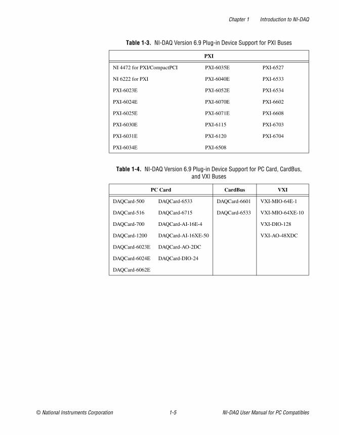
Table 1-3. NI-DAQ Version 6.9 Plug-in Device Support for PXI Buses
PXI
NI 4472 for PXI/CompactPCI PXI-6035E PXI-6527
NI 6222 for PXI PXI-6040E PXI-6533
PXI-6023E PXI-6052E PXI-6534
PXI-6024E PXI-6070E PXI-6602
PXI-6025E PXI-6071E PXI-6608
PXI-6030E PXI-6115 PXI-6703
PXI-6031E PXI-6120 PXI-6704
PXI-6034E PXI-6508
Table 1-4. NI-DAQ Version 6.9 Plug-in Device Support for PC Card, CardBus,and VXI Buses
PC Card CardBus VXI
DAQCard-500 DAQCard-6533 DAQCard-6601 VXI-MIO-64E-1
DAQCard-516 DAQCard-6715 DAQCard-6533 VXI-MIO-64XE-10
DAQCard-700 DAQCard-AI-16E-4 VXI-DIO-128
DAQCard-1200 DAQCard-AI-16XE-50 VXI-AO-48XDC
DAQCard-6023E DAQCard-AO-2DC
DAQCard-6024E DAQCard-DIO-24
DAQCard-6062E
Chapter 1 Introduction to NI-DAQ
NI-DAQ User Manual for PC Compatibles 1-6 ni.com
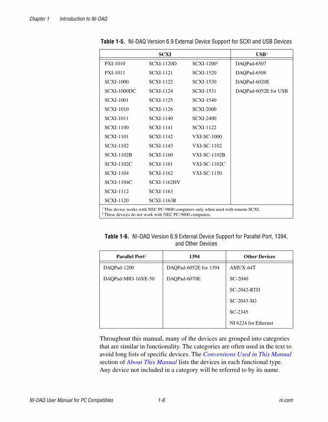
Throughout this manual, many of the devices are grouped into categoriesthat are similar in functionality. The categories are often used in the text toavoid long lists of specific devices. The Conventions Used in This Manualsection of About This Manual lists the devices in each functional type.Any device not included in a category will be referred to by its name.
Table 1-5. NI-DAQ Version 6.9 External Device Support for SCXI and USB Devices
SCXI USB2
PXI-1010 SCXI-1120D SCXI-12001 DAQPad-6507
PXI-1011 SCXI-1121 SCXI-1520 DAQPad-6508
SCXI-1000 SCXI-1122 SCXI-1530 DAQPad-6020E
SCXI-1000DC SCXI-1124 SCXI-1531 DAQPad-6052E for USB
SCXI-1001 SCXI-1125 SCXI-1540
SCXI-1010 SCXI-1126 SCXI-2000
SCXI-1011 SCXI-1140 SCXI-2400
SCXI-1100 SCXI-1141 SCXI-1122
SCXI-1101 SCXI-1142 VXI-SC-1000
SCXI-1102 SCXI-1143 VXI-SC-1102
SCXI-1102B SCXI-1160 VXI-SC-1102B
SCXI-1102C SCXI-1161 VXI-SC-1102C
SCXI-1104 SCXI-1162 VXI-SC-1150
SCXI-1104C SCXI-1162HV
SCXI-1112 SCXI-1163
SCXI-1120 SCXI-1163R
1 This device works with NEC PC-9800 computers only when used with remote SCXI.2 These devices do not work with NEC PC-9800 computers.
Table 1-6. NI-DAQ Version 6.9 External Device Support for Parallel Port, 1394,and Other Devices
Parallel Port2 1394 Other Devices
DAQPad-1200 DAQPad-6052E for 1394 AMUX-64T
DAQPad-MIO-16XE-50 DAQPad-6070E SC-2040
SC-2042-RTD
SC-2043-SG
SC-2345
NI 6224 for Ethernet
Chapter 1 Introduction to NI-DAQ
© National Instruments Corporation 1-7 NI-DAQ User Manual for PC Compatibles
NI-DAQ Language SupportNI-DAQ supplies header files, examples, and instructions on how to usean Integrated Development Environment (IDE) for one of the followinglanguages under Windows 2000/NT/98/95:
• Microsoft Visual C++ 4.X, 5.0, or 6.0
• Visual Basic 4.0 (32-bit), 5.0, or 6.0
• Borland C++ 5.X
NI-DAQ also provides an NI-DAQ function prototype file for use withBorland Delphi 2 (32-bit), 3, and 4.
Most of the files on the release media are compressed. Always run theNI-DAQ installation utilities to extract the files you want. For a briefdescription of the directories produced by the install programs andthe names and purposes of the uncompressed files, consult the NI-DAQReadme File (Start»Programs»National Instruments DAQ»NI-DAQReadme File).
Device ConfigurationBefore you begin your NI-DAQ application development, you mustconfigure your National Instruments DAQ devices, which can be plug-indevices, PC cards (PCMCIA), or external devices you connect to theparallel port of your computer. NI-DAQ needs the device configurationinformation to program your hardware properly.
Using Measurement & Automation ExplorerMeasurement & Automation Explorer is a Windows-based application thatyou use to configure and view National Instruments DAQ device settingsunder Windows 2000/NT/98/95.
Note To use Measurement & Automation Explorer, quit any applications that areperforming DAQ operations.
Double-click the Measurement & Automation icon on your desktop torun Measurement & Automation Explorer. Refer to the Measurement &Automation Explorer online help for more information and detailedinstructions.
© National Instruments Corporation 2-1 NI-DAQ User Manual for PC Compatibles
2Fundamentals of BuildingWindows Applications
This chapter describes the fundamentals of creating NI-DAQ applicationsin Windows 2000/NT/98/95.
The following section contains general information about buildingNI-DAQ applications, describes the nature of the NI-DAQ files usedin building NI-DAQ applications, and explains the basics of makingapplications using the following tools:
• Borland C++ for Windows
• Microsoft Visual C++
• Microsoft Visual Basic
If you are not using the tools listed, consult your development toolreference manual for details on creating applications that call DLLs.
The NI-DAQ LibrariesThe NI-DAQ for Windows function libraries are DLLs, which means thatNI-DAQ routines are not linked into the executable files of applications.Only the information about the NI-DAQ routines in the NI-DAQ importlibraries is stored in the executable files.
Note Use the 32-bit nidaq32.dll. If you are programming in C or C++, link in theappropriate import library. See the following sections for language-specific details.
Using function prototypes is a good programming practice. That iswhy NI-DAQ is packaged with function prototype files for differentWindows development tools. The installation utility copies the appropriateprototype files for the development tools you choose. If you are not usingany of the development tools that NI-DAQ works with, you must createyour own function prototype file.
Chapter 2 Fundamentals of Building Windows Applications
NI-DAQ User Manual for PC Compatibles 2-2 ni.com
Creating a Windows Application UsingMicrosoft Visual C++
This section assumes that you will be using the Microsoft Visual C++Integrated Development Environment (IDE) to manage your codedevelopment, and that you are familiar with the IDE.
Developing an NI-DAQ ApplicationTo develop an NI-DAQ application, follow these general steps:
1. Open an existing or new Visual C++ project to manage yourapplication code.
2. Create files of type .c (C source code) or .cpp (C++ source code)and add them to the project. Make sure you include the NI-DAQheader file, nidaq.h, as such in your source code files:
#include "nidaq.h"
You may also want to include nidaqcns.h and nidaqerr.h.Optionally, you can include other files (for example, .rc, .def) thatyou have created for graphical user interface (GUI) applications.
3. Specify the directory which contains the NI-DAQ header files underthe preprocessor»include directory settings in your compiler. (ForVisual C++ 4.X, this is under Build»Settings»C/C++. For Visual C++5.0/6.0, this is under Project»Settings»C/C++.) The NI-DAQ headerfiles are located in the .\Include directory under your NI-DAQdirectory.
4. Add the NI-DAQ import library nidaq32.lib to the project. TheNI-DAQ import library files are located in the .\Lib directory underyour NI-DAQ directory.
5. Build your application.
Example ProgramsYou can find some example programs and project files in.\Examples\VisualC directory under your NI-DAQ directory.
To load an example program, use one of the generic makefiles withthe.mak extension.
To load an example project with Visual C++ 4.X or later, select the menuoption File»Open Project Workspace, and select List Files of Type to beMakefiles. Then select the.mak file of your choice.
Chapter 2 Fundamentals of Building Windows Applications
© National Instruments Corporation 2-3 NI-DAQ User Manual for PC Compatibles
Refer to the NI-DAQ Examples Help (Start»Programs»NationalInstruments DAQ»NI-DAQ Examples Help) for additional informationregarding NI-DAQ examples.
Special Considerations
Buffer AllocationTo allocate memory, you can use the Windows API functionGlobalAlloc(). After allocation, lock memory with GlobalLock()
to use a buffer of memory. You can use the memory handle returned byGlobalLock()in place of the buffer parameter in NI-DAQ API functionsthat accept buffers (Align_DMA_Buffer, DAQ_DB_Transfer, DAQ_Monitor, DAQ_Op, DAQ_Start, DIG_Block_In, DIG_Block_Out,DIG_DB_Transfer, GPCTR_Config_Buffer, GPCTR_Read_Buffer,Lab_ISCAN_Op, Lab_ISCAN_Start, SCAN_Op, SCAN_Start,SCAN_Sequence_Demux, WFM_DB_Transfer, WFM_Load, WFM_Op).After using the memory, unlock memory with GlobalUnlock() and freeit with GlobalFree().
Note If you allocate memory from GlobalAlloc(), you must call GlobalLock() onthe memory object before passing it to NI-DAQ.
String PassingTo pass strings, pass a pointer to the first element of the character array.Be sure that the string is null-terminated.
Parameter PassingBy default, C passes parameters by value. Remember to pass pointers tovariables when you need to pass by address.
Chapter 2 Fundamentals of Building Windows Applications
NI-DAQ User Manual for PC Compatibles 2-4 ni.com
Creating a Windows Application Using MicrosoftVisual Basic
This section assumes that you will be using the Microsoft Visual BasicIDE to manage your code development, and that you are familiar withthe IDE.
Developing an NI-DAQ ApplicationTo develop an NI-DAQ application, follow these general steps:
1. Open an existing or new Visual Basic project to manage yourapplication code.
2. Create files of type.frm (form definition and event handling code),.bas (Visual Basic generic code module), or .cls (Visual Basic classmodule) and add them to the project.
3. Include the NI-DAQ include file for Visual Basic, nidaq32.bas,into your project. You may also want to include nidaqcns.inc andnidaqerr.inc. The NI-DAQ include files for Visual Basic arelocated in the .\Include directory under your NI-DAQ directory.For Visual Basic 5.0/6.0, you can select the Project»Add Modulemenu option, click on the Existing tab, then select the module of yourchoice.
Alternatively, you can add a reference to the National Instruments DataAcquisition Type Library, which is part of the NI-DAQ DLL. In VisualBasic 5.0/6.0, select the Project»References menu option, and checkNational Instruments Data Acquisition Library. If you do not see itlisted there, click on the Browse button and locate nidaq32.dll inyour \Windows\system or \Windows\system32 directory.
4. Run your application by clicking the Run button.
Note In Visual Basic, function declarations have scope globally throughout the project.In other words, you can define your prototypes in any module. The functions will berecognized even in other modules.
For information on using the NI-DAQ Visual Basic Custom Controls, see the NI-DAQEvents in Visual Basic for Windows section in Chapter 3, Software Overview.
Please also refer to the Programming Language Considerations topic in the NI-DAQFunction Reference Online Help file for more information on using the NI-DAQ functionsin Visual Basic for Windows.
Chapter 2 Fundamentals of Building Windows Applications
© National Instruments Corporation 2-5 NI-DAQ User Manual for PC Compatibles
Example ProgramsYou can find some example programs and project files in.\Examples\VBasic directory under your NI-DAQ directory.
To load an example program, use one of the Visual Basic project files withthe.vbp extension. These are Visual Basic 4.0 projects, which you canopen only with Visual Basic 4.0 or later.
To load an example project with Visual Basic 4.0 or later, select the menuoption File»Open Project, then select the.vbp file of your choice.
Refer to the NI-DAQ Examples Help (Start»Programs»NationalInstruments DAQ»NI-DAQ Examples Help) for additional informationregarding NI-DAQ examples.
Special Considerations
Buffer AllocationVisual Basic 4.0 is quite restrictive when allocating memory. Youallocate memory by declaring an array of the data type with which youwant to work. Visual Basic uses dynamic memory allocation so you canredimension an array to a variable size during run time. However, arraysare restricted to being less than 64 KB in total size (this translates to about32,767 (16-bit) integers, 16,384 (32-bit) long integers, or 8,191 doubles).
To break the 64 KB buffer size barrier, you can use the Windows APIfunctions GlobalAlloc() to allocate buffers larger than 64 KB. Afterallocation, you must lock memory with GlobalLock()to use a buffer ofmemory. You can use the memory handle returned by GlobalLock() inplace of the buffer parameter in NI-DAQ API functions that accept buffers(Align_DMA_Buffer, DAQ_DB_Transfer, DAQ_Monitor, DAQ_Op,DAQ_Start, DIG_Block_In, DIG_Block_Out, DIG_DB_Transfer,GPCTR_Config_Buffer, GPCTR_Read_Buffer, Lab_ISCAN_Op,Lab_ISCAN_Start, SCAN_Op, SCAN_Start, SCAN_Sequence_Demux,WFM_DB_Transfer, WFM_Load, WFM_Op). The NI-DAQ header filedeclares the buffer parameter “As Any.” After using the memory, you mustunlock memory with GlobalUnlock()and free it with GlobalFree().
Note If you allocate memory from GlobalAlloc(), you must call GlobalLock on thememory object before passing it to NI-DAQ.
Chapter 2 Fundamentals of Building Windows Applications
NI-DAQ User Manual for PC Compatibles 2-6 ni.com
The following paragraph illustrates declarations of functions.
For Visual Basic 4.0 or later, 32-bit:
Declare Function GlobalAlloc Lib "kernel32" Alias "GlobalAlloc" (ByVal wFlags As Long, ByVal dwBytes As Long) As Long
Declare Function GlobalFree Lib "kernel32" Alias "GlobalFree" (ByVal hMem As Long) As Long
Declare Function GlobalLock Lib "kernel32" Alias "GlobalLock" (ByVal hMem As Long) As Long
Declare Function GlobalReAlloc Lib "kernel32" Alias "GlobalReAlloc" (ByVal hMem As Long, ByVal dwBytes As Long, ByVal wFlags As Long) As Long
Declare Function GlobalUnlock Lib "kernel32" Alias "GlobalUnlock" (ByVal hMem As Long) As Long
String PassingIn Visual Basic, variables of data type String need no specialmodifications to be passed to NI-DAQ for Windows functions. VisualBasic automatically appends a null character to the end of a string beforepassing it (by reference, because strings cannot be passed by value inVisual Basic) to a procedure or function.
Parameter PassingBy default, Visual Basic passes parameters by reference. Prepend theByVal keyword if you need to pass by value.
Chapter 2 Fundamentals of Building Windows Applications
© National Instruments Corporation 2-7 NI-DAQ User Manual for PC Compatibles
Creating a Windows Application Using Borland C++This section assumes that you will be using the Borland C++ IDE tomanage your code development, and that you are familiar with the IDE.
Developing an NI-DAQ ApplicationTo develop an NI-DAQ application, follow these general steps:
1. Open an existing or new Borland C++ project to manage yourapplication code.
2. Create files of type.c (C source code) or.cpp (C++ source code) andadd them to the project.
• Make sure you include the NI-DAQ header file, nidaq.h, as suchin your source code files:
#include "nidaq.h"
• You may also want to include nidaqcns.h and nidaqerr.h.
• Optionally, you can include other files (for example,.rc,.def)for GUI applications.
3. Specify the directory that contains the NI-DAQ header and importlibrary files under the source directories (Include, Libary) settingsof your compiler. For Borland C++ 5.0, this directory is underOptions»Projects»Directories. The NI-DAQ header files are locatedin the.\Include directory under your NI-DAQ directory, and theimport library files are located in the.\Lib directory under yourNI-DAQ directory.
4. Add the NI-DAQ import library, nidaq32.lib, to the project.
5. Build your application.
Example ProgramsYou can find some example programs and project files in.\Examples\BorlandC directory under your NI-DAQ directory.
To build an example program, run one of the batch files with the.bat extension from a DOS prompt. You will have to modify the batch file toset one of the environmental variables to point to your Borland C++ IDEdirectory. If you open one of the batch files with a text editor, you will seethe following line:
set BorlandDir=e:\apps\bc5
Chapter 2 Fundamentals of Building Windows Applications
NI-DAQ User Manual for PC Compatibles 2-8 ni.com
Change the right hand side of the equal sign to indicate your Borland C++IDE directory. For help on the usage of the batch file, type<batchfile.bat> /? from a DOS prompt, where <batchfile.bat> is the file name of batch file you want to run (for example,AIonePoint.bat).
To create your own example project with Borland C++ 5.0 or later using theprovided example files, follow the steps mentioned above in Developingan NI-DAQ Application. In place of nidaq.h, make sure you includenidaqex.h. Also, make sure you include the import librarynidex32b.lib into your project in addition to nidaq32b.lib.
Refer to the NI-DAQ Examples Help (Start»Programs»NationalInstruments DAQ»NI-DAQ Examples Help) for additional informationregarding NI-DAQ examples.
Special ConsiderationsRefer to Special Considerations in the Creating a Windows ApplicationUsing Microsoft Visual C++ section.
Using Borland Delphi with NI-DAQThe NI-DAQ installer installs a prototype file for use with BorlandDelphi 2.0 or later, which is stored in the .\Include directory inyour NI-DAQ directory. To use this prototype file, include the filenidaq.pas into your Borland Delphi project, and be sure to includethis line in your Delphi source code:
uses NIDAQ;
Note There are no examples written with the NI-DAQ API for Borland Delphi. Forexamples on NI-DAQ function flow, refer to the examples of other languages and theflowchart in Chapter 3, Software Overview. Refer to the note at the end of the NI-DAQExamples section of this chapter for information on examples using ComponentWorksActiveX controls.
Chapter 2 Fundamentals of Building Windows Applications
© National Instruments Corporation 2-9 NI-DAQ User Manual for PC Compatibles
NI-DAQ ExamplesThe NI-DAQ installer installs a suite of concisely written examples in thefollowing application development environments:
• LabWindows/CVI 5.0.x
• Microsoft Visual C++ 2.x (32-bit) or later
• Microsoft Visual Basic 4.0 (32-bit) or later
• Borland C++ 5.0
These examples illustrate how to use NI-DAQ functions to perform a singletask. All examples are devoid of any code to extract values from GUIobjects so that you can focus on how the code flow is formed. In addition,most parameters are hardcoded at the top of the routine so that if you decideto change them, you can simply change the assignment.
The examples correspond to the function flowcharts that you will see inChapter 3, Software Overview. If a task and a flowchart in the followingchapter suits your data acquisition needs, you should find a correspondingexample to get you started.
Each example consists of the following files:
• An appropriate project file for the programming language (except forBorland C++, where .bat files are included to help build theexecutable)
• A single source code file to illustrate the task at hand
• A library of NI-DAQ example utility functions (for buffer creation,waveform plotting, error checking, and implementing a delay)
Note None of the examples are installed in their executable (.exe) format. To run them,you first must build them or load them into the IDE for the appropriate programminglanguage.
The examples are stored in the hierarchy shown below for each language:
.\AI Analog Input examples
.\AO Analog Output examples
.\DI Digital Input examples
.\DO Digital Output examples
.\CTR Counter/timer examples
.\SCXI SCXI examples
.\CALIB Calibration examples
Chapter 2 Fundamentals of Building Windows Applications
NI-DAQ User Manual for PC Compatibles 2-10 ni.com
The project files have the same file name (not including extension) as thesource code files. The following types are installed:
• LabWindows/CVI:
.prj (project file), .c (source file)
• Visual C++:
.mak (generic make file), .c (source file)
• Visual Basic:
.vbp (project file, for Visual Basic 4.0 [32-bit] or later),
.frm (form module)
• Borland C++:
.bat (Batchfile), .c (source file)
For more information about each example, how to compile examples,and details on the NI-DAQ Example Utility functions, please refer tothe NI-DAQ Examples Online Help file. To open this file, go toStart»Programs»National Instruments DAQ»NI-DAQ ExamplesHelp. You will have this file only if you installed support forLabWindows/CVI, Visual C++, Visual Basic, or Borland C++ examples.
In addition to examples using the NI-DAQ API, you can install and useexamples using the ComponentWorks DAQ controls.
Run the NI-DAQ Setup Utility (Start»Programs»National InstrumentsDAQ»NI-DAQ Setup) and choose either of the following:
• Microsoft Visual Basic (under Details, select ComponentWorksActiveX Controls and ComponentWorks DAQ Visual BasicExamples)
• Borland Delphi (under Details, select ComponentWorks ActiveXControls and ComponentWorks DAQ Borland Delphi Examples)
These examples will be installed in the .\Examples\Visual Basic and.\Examples\Borland Delphi directories, respectively, under yourNI-DAQ directory.
© National Instruments Corporation 3-1 NI-DAQ User Manual for PC Compatibles
3Software Overview
This chapter describes the function classes in NI-DAQ and brieflydescribes each function.
NI-DAQ functions are grouped according to the following classes:
• Initialization and general-configuration
• Software-calibration and device-specific
• Event message
• Analog input function group
– One-shot analog input
• Single-channel analog input
– Data acquisition
• High-level data acquisition
• Low-level data acquisition
• Low-level double-buffered data acquisition
• Analog output function group
– One-shot analog output
– Waveform generation
• High-level waveform generation
• Low-level waveform generation
• Digital I/O function group
– Digital I/O
– Group digital I/O
• Double-buffered digital I/O
– Change Notification
– Filtering
• Counter/Timer function group
– Counter/timer
– Interval counter/timer
– General-purpose counter/timer
Chapter 3 Software Overview
NI-DAQ User Manual for PC Compatibles 3-2 ni.com
• RTSI bus trigger
• SCXI
• Transducer conversion
Initialization and General-Configuration FunctionsUse these general functions for initializing and configuring your hardwareand software.
Refer to the NI-DAQ Function Reference Online Help file to determinewhich functions your device supports.
Align_DMA_Buffer Aligns the data in a DMA buffer to avoidcrossing a physical page boundary. Thisfunction is for use with DMA waveformgeneration and digital I/O patterngeneration.
Get_DAQ_Device_Info Retrieves parameters pertaining to thedevice operation.
Get_NI_DAQ_Version Returns the version number of the NI-DAQlibrary.
Init_DA_Brds Initializes the hardware and software statesof a National Instruments DAQ device toits default state and then returns a numericdevice code that corresponds to the type ofdevice initialized. Any operation that thedevice is performing is halted. NI-DAQautomatically calls this function; yourapplication does not have to call itexplicitly. This function is useful forreinitializing the device hardware, forreinitializing the NI-DAQ software, andfor determining which device has beenassigned to a particular slot number.
Chapter 3 Software Overview
© National Instruments Corporation 3-3 NI-DAQ User Manual for PC Compatibles
Set_DAQ_Device_Info Selects parameters pertaining to the deviceoperation.
Timeout_Config Establishes a timeout limit that is used bythe synchronous functions to ensure thatthese functions eventually return control toyour application. Examples of synchronousfunctions are DAQ_Op,DAQ_DB_Transfer, andWFM_from_Disk.
Software-Calibration and Device-Specific FunctionsEach of these software-calibration and configuration functions is specificto only one type of device or class of devices.
Refer to the NI-DAQ Function Reference Online Help file to determinewhich functions your device supports.
AO_Calibrate Loads a set of calibration constants intothe calibration DACs or copies a set ofcalibration constants from one of fourEEPROM areas to EEPROM area 1. Youcan load an existing set of calibrationconstants into the calibration DACs froma storage area in the onboard EEPROM.You can copy EEPROM storage areas2 through 5 (EEPROM area 5 contains thefactory-calibration constants) to storagearea 1. NI-DAQ automatically loads thecalibration constants stored in EEPROMarea 1 the first time a function pertaining tothe AT-AO-6/10 is called.
Calibrate_1200 Calibrates the gain and offset values forthe 1200/AI devices ADCs and DACs. Youcan perform a new calibration or use anexisting set of calibration constants bycopying the constants from their storagelocation in the onboard EEPROM. You canstore up to six sets of calibration constants.
Chapter 3 Software Overview
NI-DAQ User Manual for PC Compatibles 3-4 ni.com
NI-DAQ automatically loads thecalibration constants stored in EEPROMuser area 5 the first time you call a functionpertaining to the device.
Calibrate_TIO Use the function to calibrate the crystaloscillator on your timing I/O 660X device.
Calibrate_DSA Use this function to calibrate yourDSA device.
Calibrate_E_Series Use this function to calibrate your E Seriesdevice or 671X device and to select a setof calibration constants for NI-DAQ to use.
Configure_HW_Analog_Trigger
Configures the hardware analog triggeravailable on your E Series device.
LPM16_Calibrate Calibrates the LPM device converter.The function calculates the correct offsetvoltage for the voltage comparator, adjustspositive linearity and full-scale errors toless than ±0.5 LSB each, and adjusts zeroerror to less than ±1 LSB.
MIO_Config Turns dithering on and off. For theMIO-64, this function also lets you specifywhether to use AMUX-64T channels oronboard channels.
SCXI_Calibrate Performs a self-calibration (or internalcalibration) for certain SCXI modules.
Select_Signal Selects the source and polarity of certainsignals used by the E Series and DSAdevices. You typically need to use thisfunction to externally control timing, touse the RTSI bus, or to configure one ofthe I/O connector PFI pins.
Chapter 3 Software Overview
© National Instruments Corporation 3-5 NI-DAQ User Manual for PC Compatibles
Event Message FunctionsNI-DAQ Event Message functions are an efficient way to monitor yourbackground data acquisition processes, without dedicating your foregroundprocess for status checking.
The NI-DAQ Event Message dispatcher notifies your application when auser-specified DAQ event occurs. Using event messaging eliminatescontinuous polling of data acquisition processes.
Config_Alarm_Deadband Specify alarm on/off condition for dataacquisition event messaging.
Config_ATrig_Event_Message
Specify analog input trigger level and slopefor data acquisition event messaging.
Config_DAQ_Event_Message
Specify analog input, analog output, digitalinput, or digital output trigger condition forevent messaging.
Event Messaging Application TipsTo receive notification from the NI-DAQ data acquisition process incase of special events, you can call Config_Alarm_Deadband,Config_ATrig_Event_Message, or Config_DAQ_Event_Messageto specify an event in which you are interested. If you are interested in morethan one event, you can call any of those three functions again for eachevent.
After you have configured all event messages, you can begin your dataacquisition by calling SCAN_Start, DIG_Block_In, and so on.
When any of the events you specified occur, NI-DAQ notifies yourapplication.
Event notification can be done through user-defined callbacks and/or theWindows Message queue. When a user-specified event occurs, NI-DAQcalls the user-defined callback (if defined) and/or puts a message into theWindows Message queue, if you specified a window handle. Yourapplication receives the message when it calls the WindowsGetMessage API.
Chapter 3 Software Overview
NI-DAQ User Manual for PC Compatibles 3-6 ni.com
After your application receives an event message, it can carry out theappropriate task, such as updating the screen or saving data to disk.
To restart your data acquisition process after it completes, you do not needto call the message configuration calls again. They remain defined as longas your application does not explicitly remove them or callInit_DA_Brds.
To add or remove a message, first clear your data acquisition process.Then, call one of the three event message configuration functions.
NI-DAQ Events in Visual Basic for Windows
ActiveX Controls for Visual BasicUnlike standard control-flow programming languages, event occurrencesdrive Visual Basic code. You interact with outside events through theproperties and procedures of a control. For any given control, there is aset of procedures called event procedures that affect that control.For example, a command button named Run has a procedure calledRun_Click() that is called when you click on the Run button. If youwant something to run when you click the Run button, enter code in theRun_Click() procedure. When a program starts executing, Visual Basiclooks for events related to controls and calls control procedures asnecessary. You do not write an event loop.
There are three NI-DAQ ActiveX controls for Visual Basic applications:
• General Data Acquisition Event (daqevent.ocx)
• Analog Trigger Event (atrigev.ocx)
• Analog Alarm Event (alarmev.ocx)
The NI-DAQ installer places all of these ActiveX controls in the NIDAQsubdirectory of your Windows 2000/NT/98/95 directory under the filenames shown.
Chapter 3 Software Overview
© National Instruments Corporation 3-7 NI-DAQ User Manual for PC Compatibles
These three ActiveX controls actually call the NI-DAQConfig_DAQ_Event_Message, Config_ATrig_Event_Message andConfig_Alarm_Deadband functions. Visual Basic applications cannotreceive Windows messages, but if you use NI-DAQ ActiveX controlsshown previously in this section, your Visual Basic application can receiveNI-DAQ messages.
Note You can use the OCXs in Visual Basic, version 4.0 (32-bit) or later.
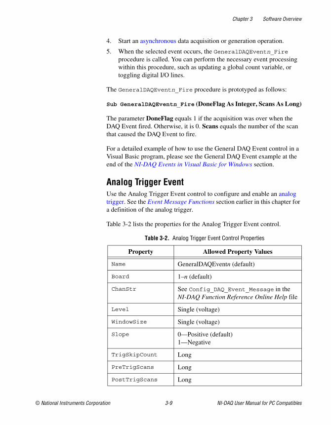
General DAQ EventYou use the General DAQ Event control to configure and enable a singledata acquisition event. See the Event Message Functions section earlier inthis chapter for a complete description of NI-DAQ events. Table 3-1 liststhe properties for the General DAQ Event control.
Note An n represents a generic number and is not the same value in every occurrence.
Table 3-1. General DAQ Event Control Properties
Property Allowed Property Values
Name GeneralDAQEventn (default)
Board 1–n (default)
ChanStr See Config_DAQ_Event_Message in theNI-DAQ Function Reference Online Help file.
DAQEvent 0—Acquired or generated n scans1—Every n scans2—Completed operation or stopped by error3—Voltage out of bounds4—Voltage within bounds5—Analog positive slope triggering6—Analog negative slope triggering7—Digital pattern not matched8—Digital pattern matched9—Counter pulse event
DAQTrigVal0 Long
DAQTrigVal1 Long
TrigSkipCount Long
Chapter 3 Software Overview
NI-DAQ User Manual for PC Compatibles 3-8 ni.com
Some General DAQ Events can be implemented only by a select groupof National Instruments DAQ devices. Also, some General DAQ Eventsrequire that you set the asynchronous data acquisition or generationoperation to use interrupts. For more information on the differenttypes of General DAQ Events, refer to the description for theConfig_DAQ_Event_Message function in the NI-DAQ FunctionReference Online Help file.
Set each of these properties as follows:
GeneralDAQEventn.property name = property value
For example, to set the ChanStr property to Analog Input channel 0 forGeneralDAQEvent 1:
GeneralDAQEvent1.ChanStr = "AI0"
Set up your program flow like this:
1. Set the properties of the General DAQ Event control. Then, configurethe acquisition or generation operations using the appropriate NI-DAQfunctions.
2. Set the Enabled property of the General DAQ Event controlto 1 (True).
3. Invoke the GeneralDAQEventn.Refresh method to set theDAQ Event in the NI-DAQ driver. Each subsequent use ofGeneralDAQEventn.Refresh deletes the old DAQ Event andsets a new one with the current set of properties.
PreTrigScans Long
PostTrigScans Long
Index N/A
Tag N/A
Enabled 0—False (default)1—True
Table 3-1. General DAQ Event Control Properties (Continued)
Property Allowed Property Values
Chapter 3 Software Overview
© National Instruments Corporation 3-9 NI-DAQ User Manual for PC Compatibles
4. Start an asynchronous data acquisition or generation operation.
5. When the selected event occurs, the GeneralDAQEventn_Fireprocedure is called. You can perform the necessary event processingwithin this procedure, such as updating a global count variable, ortoggling digital I/O lines.
The GeneralDAQEventn_Fire procedure is prototyped as follows:
Sub GeneralDAQEventn_Fire (DoneFlag As Integer, Scans As Long)
The parameter DoneFlag equals 1 if the acquisition was over when theDAQ Event fired. Otherwise, it is 0. Scans equals the number of the scanthat caused the DAQ Event to fire.
For a detailed example of how to use the General DAQ Event control in aVisual Basic program, please see the General DAQ Event example at theend of the NI-DAQ Events in Visual Basic for Windows section.
Analog Trigger EventUse the Analog Trigger Event control to configure and enable an analogtrigger. See the Event Message Functions section earlier in this chapter fora definition of the analog trigger.
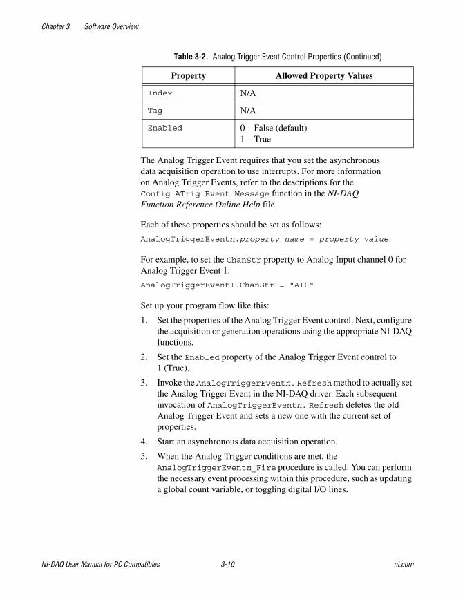
Table 3-2 lists the properties for the Analog Trigger Event control.
Table 3-2. Analog Trigger Event Control Properties
Property Allowed Property Values
Name GeneralDAQEventn (default)
Board 1–n (default)
ChanStr See Config_DAQ_Event_Message in theNI-DAQ Function Reference Online Help file
Level Single (voltage)
WindowSize Single (voltage)
Slope 0—Positive (default)1—Negative
TrigSkipCount Long
PreTrigScans Long
PostTrigScans Long
Chapter 3 Software Overview
NI-DAQ User Manual for PC Compatibles 3-10 ni.com
The Analog Trigger Event requires that you set the asynchronousdata acquisition operation to use interrupts. For more informationon Analog Trigger Events, refer to the descriptions for theConfig_ATrig_Event_Message function in the NI-DAQFunction Reference Online Help file.
Each of these properties should be set as follows:
AnalogTriggerEventn.property name = property value
For example, to set the ChanStr property to Analog Input channel 0 forAnalog Trigger Event 1:
AnalogTriggerEvent1.ChanStr = "AI0"
Set up your program flow like this:
1. Set the properties of the Analog Trigger Event control. Next, configurethe acquisition or generation operations using the appropriate NI-DAQfunctions.
2. Set the Enabled property of the Analog Trigger Event control to1 (True).
3. Invoke the AnalogTriggerEventn. Refreshmethod to actually setthe Analog Trigger Event in the NI-DAQ driver. Each subsequentinvocation of AnalogTriggerEventn. Refresh deletes the oldAnalog Trigger Event and sets a new one with the current set ofproperties.
4. Start an asynchronous data acquisition operation.
5. When the Analog Trigger conditions are met, theAnalogTriggerEventn_Fire procedure is called. You can performthe necessary event processing within this procedure, such as updatinga global count variable, or toggling digital I/O lines.
Index N/A
Tag N/A
Enabled 0—False (default)1—True
Table 3-2. Analog Trigger Event Control Properties (Continued)
Property Allowed Property Values
Chapter 3 Software Overview
© National Instruments Corporation 3-11 NI-DAQ User Manual for PC Compatibles
The AnalogTriggerEventn_Fire procedure is prototyped as follows:
Sub AnalogTriggerEventn_Fire (DoneFlag As Integer,Scans As Long)
The parameter DoneFlag equals 1 if the acquisition was over when theAnalog Trigger Event fired. Otherwise, it is 0. Scans equals the number ofthe scan that caused the Analog Trigger Event to fire.
Analog Alarm EventUse the Analog Alarm Event control to configure and enable an analogtrigger. See the Event Message Functions section earlier in this chapter fora definition of the analog trigger.
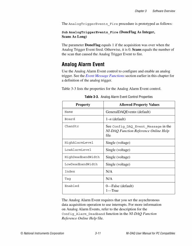
Table 3-3 lists the properties for the Analog Alarm Event control.
The Analog Alarm Event requires that you set the asynchronousdata acquisition operation to use interrupts. For more informationon Analog Alarm Events, refer to the description for theConfig_Alarm_Deadband function in the NI-DAQ FunctionReference Online Help file.
Table 3-3. Analog Alarm Event Control Properties
Property Allowed Property Values
Name GeneralDAQEventn (default)
Board 1–n (default)
ChanStr See Config_DAQ_Event_Message in theNI-DAQ Function Reference Online Helpfile
HighAlarmLevel Single (voltage)
LowAlarmLevel Single (voltage)
HighDeadbandWidth Single (voltage)
LowDeadbandWidth Single (voltage)
Index N/A
Tag N/A
Enabled 0—False (default)1—True
Chapter 3 Software Overview
NI-DAQ User Manual for PC Compatibles 3-12 ni.com
Each of these properties should be set as follows:
AnalogAlarmEventn.property name = property value
For instance, to set the ChanStr property to Analog Input channel 0 forAnalog Alarm Event 1:
AnalogAlarmEvent1.ChanStr = "AI0"
Set up your program flow like this:
1. Set the properties of the Analog Alarm Event control. Next configurethe acquisition or generation operations using the appropriate NI-DAQfunctions.
2. Set the Enabled property of the Analog Alarm Event control to1 (True).
3. Invoke the AnalogAlarmEventn.Refreshmethod to set the AnalogAlarm Event in the NI-DAQ driver. Each subsequent invocation ofAnalogAlarmEventn.Refresh deletes the old Analog Alarm Eventand sets a new one with the current set of properties.
4. Start an asynchronous data acquisition operation.
5. Call any one of the four following procedures:
• AnalogAlarm_HighAlarmOn
• AnalogAlarm_HighAlarmOff
• AnalogAlarm_LowAlarmOn
• AnalogAlarm_LowAlarmOff
You can perform necessary event processing within this procedure,such as updating a global count variable or toggling digital I/O lines.
The four Analog Alarm procedures are prototyped as follows:
Sub AnalogAlarmn_HighAlarmOn (DoneFlag As Integer,Scans As Long)
Sub AnalogAlarmn_HighAlarmOff (DoneFlag As Integer,Scans As Long)
Sub AnalogAlarmn_LowAlarmOn (DoneFlag As Integer,Scans As Long)
Sub AnalogAlarmn_LowAlarmOff (DoneFlag As Integer,Scans As Long)
Chapter 3 Software Overview
© National Instruments Corporation 3-13 NI-DAQ User Manual for PC Compatibles
The parameter DoneFlag equals 1 if the acquisition was over when theAnalog Alarm Event fired. Otherwise, it is 0. Scans equals the number ofthe scan that caused the Analog Alarm Event to fire.
Using Multiple ControlsIn general, a program might contain any number of General DAQ Event,Analog Trigger Event, and Analog Alarm Event controls. Just like regularVisual Basic controls, there are two ways you can place multiple controlson a Visual Basic form:
• You can create control arrays by copying and pasting a control thatalready exists on the form. Each individual element in the control arrayis then distinguished by the Index property, and the event proceduresis an extra parameter Index as Integer. The first element hasIndex = 0, the second element has Index = 1, and so on. You haveonly one procedure for each type of event custom control; however,you can determine which control array element caused the event tooccur by examining the Index property.
• You can place multiple controls from the Visual Basic Tool Box ontothe form. Each individual custom control of the same type is thendistinguished by the number after the name of the custom control,such as GeneralDAQEvent1, GeneralDAQEvent2, and so on.Consequently, you can have separate procedures for each customcontrol, such as GeneralDAQEvent1_Fire, GeneralDAQEvent2_Fire, and so on.
General DAQ Event ExampleThe following steps provide an outline of how to use the General DAQEvent control in a Visual Basic program. A working knowledge of VisualBasic is assumed; otherwise, this example is complete, except for errorchecking:
1. To use the GeneralDAQEvent control, you must first include the propercontrol into your project.
• If you are using Visual Basic 4.0 (32-bit), select theTools»Custom Controls option, and select the NationalInstruments GeneralDAQEvent custom control.
• If you are using Visual Basic 5.0, select theProject»Components option, and select the NationalInstruments GeneralDAQEvent custom control. In eitherversion, if you do not find the custom control listed, click on theBrowse button and find the custom control in the NI-DAQsubdirectory under your Windows directory.
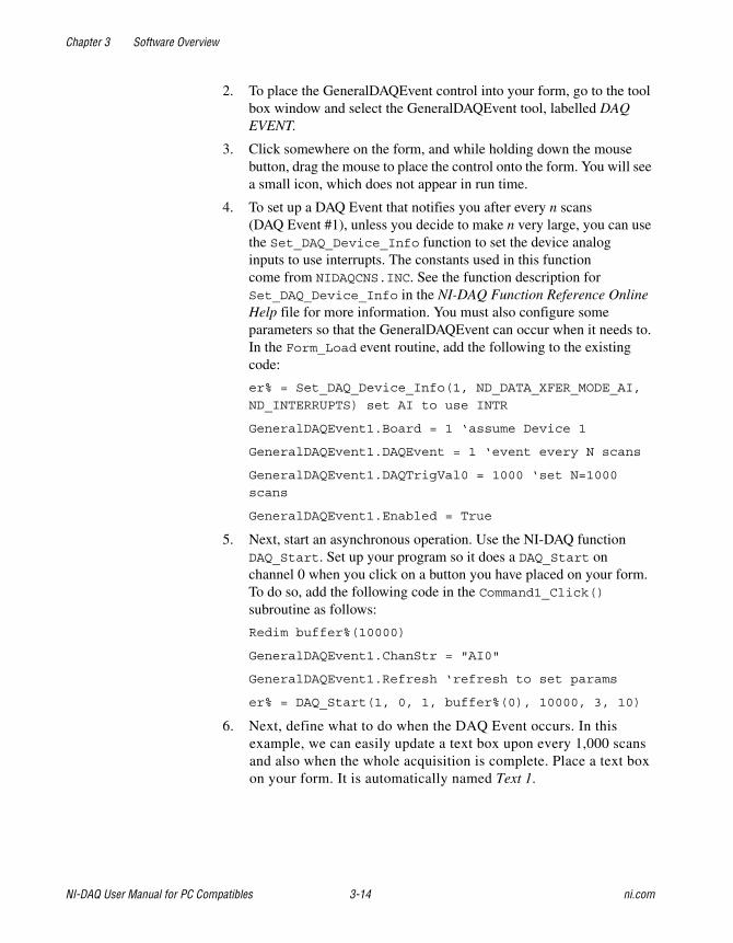
Chapter 3 Software Overview
NI-DAQ User Manual for PC Compatibles 3-14 ni.com
2. To place the GeneralDAQEvent control into your form, go to the toolbox window and select the GeneralDAQEvent tool, labelled DAQEVENT.
3. Click somewhere on the form, and while holding down the mousebutton, drag the mouse to place the control onto the form. You will seea small icon, which does not appear in run time.
4. To set up a DAQ Event that notifies you after every n scans(DAQ Event #1), unless you decide to make n very large, you can usethe Set_DAQ_Device_Info function to set the device analoginputs to use interrupts. The constants used in this functioncome from NIDAQCNS.INC. See the function description forSet_DAQ_Device_Info in the NI-DAQ Function Reference OnlineHelp file for more information. You must also configure someparameters so that the GeneralDAQEvent can occur when it needs to.In the Form_Load event routine, add the following to the existingcode:
er% = Set_DAQ_Device_Info(1, ND_DATA_XFER_MODE_AI,
ND_INTERRUPTS) set AI to use INTR
GeneralDAQEvent1.Board = 1 ‘assume Device 1
GeneralDAQEvent1.DAQEvent = 1 ‘event every N scans
GeneralDAQEvent1.DAQTrigVal0 = 1000 ‘set N=1000
scans
GeneralDAQEvent1.Enabled = True
5. Next, start an asynchronous operation. Use the NI-DAQ functionDAQ_Start. Set up your program so it does a DAQ_Start onchannel 0 when you click on a button you have placed on your form.To do so, add the following code in the Command1_Click()subroutine as follows:
Redim buffer%(10000)
GeneralDAQEvent1.ChanStr = "AI0"
GeneralDAQEvent1.Refresh ‘refresh to set params
er% = DAQ_Start(1, 0, 1, buffer%(0), 10000, 3, 10)
6. Next, define what to do when the DAQ Event occurs. In thisexample, we can easily update a text box upon every 1,000 scansand also when the whole acquisition is complete. Place a text boxon your form. It is automatically named Text 1.
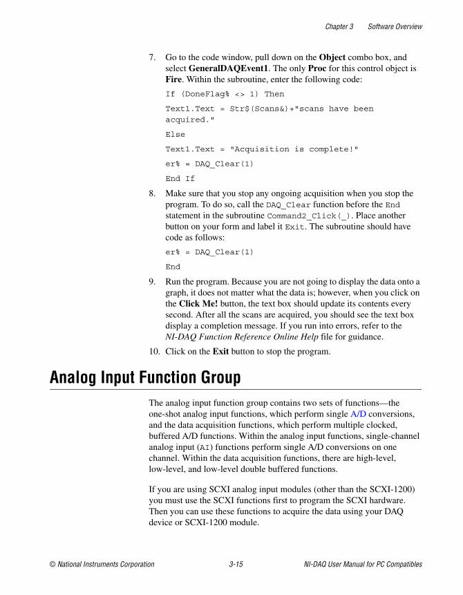
Chapter 3 Software Overview
© National Instruments Corporation 3-15 NI-DAQ User Manual for PC Compatibles
7. Go to the code window, pull down on the Object combo box, andselect GeneralDAQEvent1. The only Proc for this control object isFire. Within the subroutine, enter the following code:
If (DoneFlag% <> 1) Then
Text1.Text = Str$(Scans&)+"scans have been
acquired."
Else
Text1.Text = "Acquisition is complete!"
er% = DAQ_Clear(1)
End If
8. Make sure that you stop any ongoing acquisition when you stop theprogram. To do so, call the DAQ_Clear function before the Endstatement in the subroutine Command2_Click(_). Place anotherbutton on your form and label it Exit. The subroutine should havecode as follows:
er% = DAQ_Clear(1)
End
9. Run the program. Because you are not going to display the data onto agraph, it does not matter what the data is; however, when you click onthe Click Me! button, the text box should update its contents everysecond. After all the scans are acquired, you should see the text boxdisplay a completion message. If you run into errors, refer to theNI-DAQ Function Reference Online Help file for guidance.
10. Click on the Exit button to stop the program.
Analog Input Function GroupThe analog input function group contains two sets of functions—theone-shot analog input functions, which perform single A/D conversions,and the data acquisition functions, which perform multiple clocked,buffered A/D functions. Within the analog input functions, single-channelanalog input (AI) functions perform single A/D conversions on onechannel. Within the data acquisition functions, there are high-level,low-level, and low-level double buffered functions.
If you are using SCXI analog input modules (other than the SCXI-1200)you must use the SCXI functions first to program the SCXI hardware.Then you can use these functions to acquire the data using your DAQdevice or SCXI-1200 module.
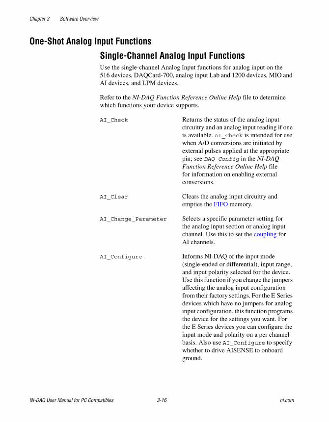
Chapter 3 Software Overview
NI-DAQ User Manual for PC Compatibles 3-16 ni.com
One-Shot Analog Input Functions
Single-Channel Analog Input FunctionsUse the single-channel Analog Input functions for analog input on the516 devices, DAQCard-700, analog input Lab and 1200 devices, MIO andAI devices, and LPM devices.
Refer to the NI-DAQ Function Reference Online Help file to determinewhich functions your device supports.
AI_Check Returns the status of the analog inputcircuitry and an analog input reading if oneis available. AI_Check is intended for usewhen A/D conversions are initiated byexternal pulses applied at the appropriatepin; see DAQ_Config in the NI-DAQFunction Reference Online Help filefor information on enabling externalconversions.
AI_Clear Clears the analog input circuitry andempties the FIFO memory.
AI_Change_Parameter Selects a specific parameter setting forthe analog input section or analog inputchannel. Use this to set the coupling forAI channels.
AI_Configure Informs NI-DAQ of the input mode(single-ended or differential), input range,and input polarity selected for the device.Use this function if you change the jumpersaffecting the analog input configurationfrom their factory settings. For the E Seriesdevices which have no jumpers for analoginput configuration, this function programsthe device for the settings you want. Forthe E Series devices you can configure theinput mode and polarity on a per channelbasis. Also use AI_Configure to specifywhether to drive AISENSE to onboardground.
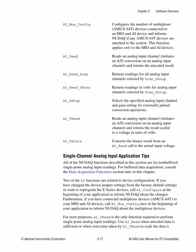
Chapter 3 Software Overview
© National Instruments Corporation 3-17 NI-DAQ User Manual for PC Compatibles
AI_Mux_Config Configures the number of multiplexer(AMUX-64T) devices connected toan MIO and AI device and informsNI-DAQ if any AMUX-64T devices areattached to the system. This functionapplies only to the MIO and AI devices.
AI_Read Reads an analog input channel (initiatesan A/D conversion on an analog inputchannel) and returns the unscaled result.
AI_Read_Scan Returns readings for all analog inputchannels selected by Scan_Setup.
AI_Read_VScan Returns readings in volts for analog inputchannels selected by Scan_Setup.
AI_Setup Selects the specified analog input channeland gain setting for externally pulsedconversion operations.
AI_VRead Reads an analog input channel (initiatesan A/D conversion on an analog inputchannel) and returns the result scaledto a voltage in units of volts.
AI_VScale Converts the binary result from anAI_Read call to the actual input voltage.
Single-Channel Analog Input Application TipsAll of the NI-DAQ functions described in this section are for nonbufferedsingle-point analog input readings. For buffered data acquisition, consultthe Data Acquisition Functions section later in this chapter.
Two of the AI functions are related to device configuration. If youhave changed the device jumper settings from the factory-default settingsor want to reprogram the E Series devices, call AI_Configure at thebeginning of your application to inform NI-DAQ about the changes.Furthermore, if you have connected multiplexer devices (AMUX-64T) toyour MIO and AI devices, call AI_Mux_Config once at the beginning ofyour application to inform NI-DAQ about the multiplexer devices.
For most purposes, AI_VRead is the only function required to performsingle-point analog input readings. Use AI_Read when unscaled data issufficient or when extra time taken by AI_VRead to scale the data is
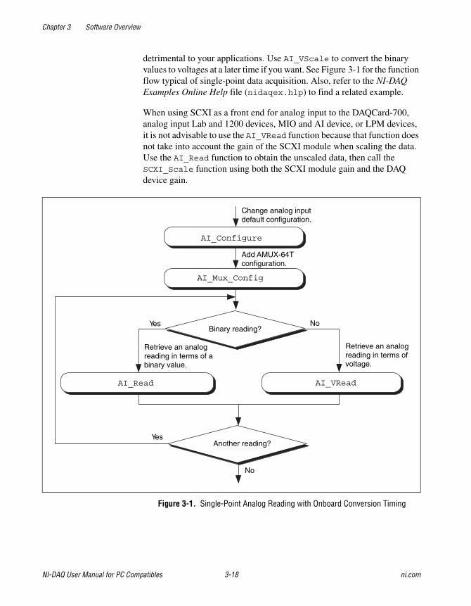
Chapter 3 Software Overview
NI-DAQ User Manual for PC Compatibles 3-18 ni.com
detrimental to your applications. Use AI_VScale to convert the binaryvalues to voltages at a later time if you want. See Figure 3-1 for the functionflow typical of single-point data acquisition. Also, refer to the NI-DAQExamples Online Help file (nidaqex.hlp) to find a related example.
When using SCXI as a front end for analog input to the DAQCard-700,analog input Lab and 1200 devices, MIO and AI device, or LPM devices,it is not advisable to use the AI_VRead function because that function doesnot take into account the gain of the SCXI module when scaling the data.Use the AI_Read function to obtain the unscaled data, then call theSCXI_Scale function using both the SCXI module gain and the DAQdevice gain.
Figure 3-1. Single-Point Analog Reading with Onboard Conversion Timing
No
Yes
Yes
No
Another reading?
AI_VReadAI_Read
Binary reading?
AI_Mux_Config
AI_Configure
Retrieve an analogreading in terms of abinary value.
Retrieve an analogreading in terms ofvoltage.
Add AMUX-64Tconfiguration.
Change analog inputdefault configuration.
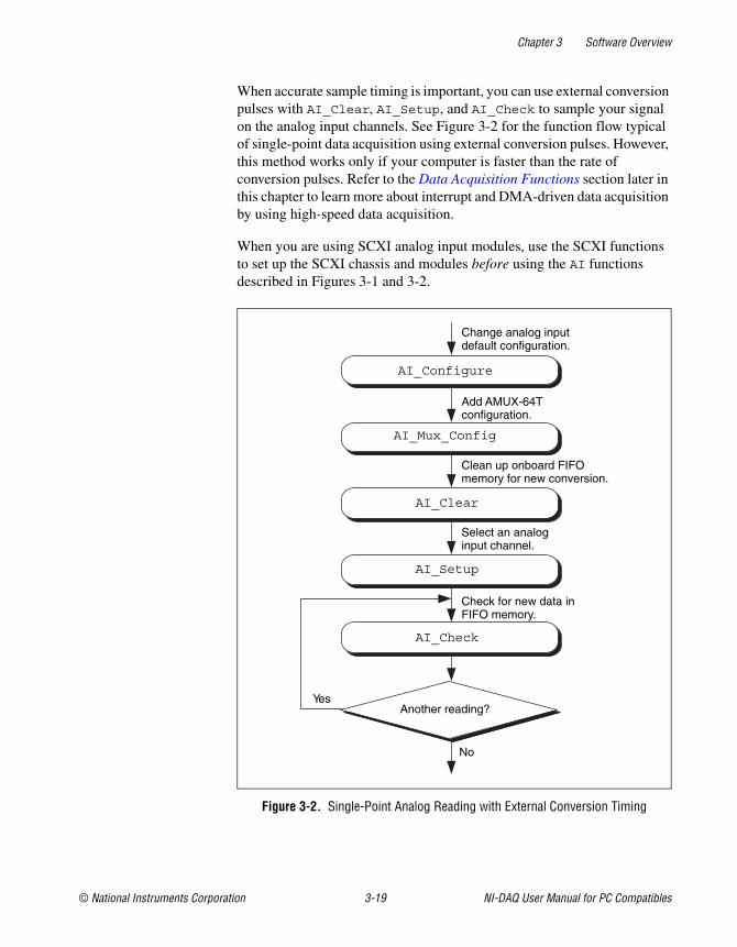
Chapter 3 Software Overview
© National Instruments Corporation 3-19 NI-DAQ User Manual for PC Compatibles
When accurate sample timing is important, you can use external conversionpulses with AI_Clear, AI_Setup, and AI_Check to sample your signalon the analog input channels. See Figure 3-2 for the function flow typicalof single-point data acquisition using external conversion pulses. However,this method works only if your computer is faster than the rate ofconversion pulses. Refer to the Data Acquisition Functions section later inthis chapter to learn more about interrupt and DMA-driven data acquisitionby using high-speed data acquisition.
When you are using SCXI analog input modules, use the SCXI functionsto set up the SCXI chassis and modules before using the AI functionsdescribed in Figures 3-1 and 3-2.
Figure 3-2. Single-Point Analog Reading with External Conversion Timing
Yes
No
Another reading?
AI_Clear
AI_Mux_Config
AI_Configure
AI_Check
AI_Setup
Change analog inputdefault configuration.
Add AMUX-64Tconfiguration.
Clean up onboard FIFOmemory for new conversion.
Select an analoginput channel.
Check for new data inFIFO memory.
Chapter 3 Software Overview
NI-DAQ User Manual for PC Compatibles 3-20 ni.com
Data Acquisition Functions
High-Level Data Acquisition FunctionsThese high-level data acquisition functions are synchronous calls thatacquire data and return when data acquisition is complete.
Refer to the NI-DAQ Function Reference Online Help file to determinewhich functions your device supports.
DAQ_Op Performs a synchronous, single-channeldata acquisition operation. DAQ_Op doesnot return until NI-DAQ has acquired allthe data or an acquisition error hasoccurred.
DAQ_to_Disk Performs a synchronous, single-channeldata acquisition operation and saves theacquired data in a disk file. DAQ_to_Diskdoes not return until NI-DAQ has acquiredand saved all the data or an acquisitionerror has occurred.
Lab_ISCAN_Op Performs a synchronous, multiple-channelscanned data acquisition operation.Lab_ISCAN_Op does not return untilNI-DAQ has acquired all the data or anacquisition error has occurred.
Lab_ISCAN_to_Disk Performs a synchronous, multiple-channelscanned data acquisition operation andsimultaneously saves the acquired data in adisk file. Lab_ISCAN_to_Disk does notreturn until NI-DAQ has acquired all thedata and saved all the data or an acquisitionerror has occurred.
Chapter 3 Software Overview
© National Instruments Corporation 3-21 NI-DAQ User Manual for PC Compatibles
SCAN_Op Performs a synchronous, multiple-channelscanned data acquisition operation.SCAN_Op does not return until NI-DAQ hasacquired all the data or an acquisition errorhas occurred.
SCAN_to_Disk Performs a synchronous, multiple-channelscanned data acquisition operation andsimultaneously saves the acquired data in adisk file. SCAN_to_Disk does not returnuntil NI-DAQ has acquired all the data andsaved it or until an acquisition error hasoccurred.
Low-Level Data Acquisition FunctionsThese functions are low-level primitives used for setting up, starting, andmonitoring asynchronous data acquisition operations.
Refer to the NI-DAQ Function Reference Online Help file to determinewhich functions your device supports.
DAQ_Check Checks if the current data acquisitionoperation is complete and returns the statusand the number of samples acquired to thatpoint.
DAQ_Clear Cancels the current data acquisitionoperation (both single-channel andmultiple-channel scanned) and reinitializesthe data acquisition circuitry.
DAQ_Config Stores configuration information forsubsequent data acquisition operations.
DAQ_Monitor Returns data from an asynchronousdata acquisition in progress. During amultiple-channel acquisition, you can callDAQ_Monitor to retrieve data from asingle channel or from all channels beingscanned. Using the oldest/newest mode,you can specify whether DAQ_Monitorreturns sequential (oldest) blocks of data,or the most recently acquired (newest)blocks of data.
Chapter 3 Software Overview
NI-DAQ User Manual for PC Compatibles 3-22 ni.com
DAQ_Rate Converts a data acquisition rate into thetimebase and sample-interval valuesneeded to produce the rate you want.
DAQ_Set_Clock Sets the scan rate for a group of channels.
DAQ_Start Initiates an asynchronous, single-channeldata acquisition operation and stores itsinput in an array.
DAQ_StopTrigger_Config Enables the pretrigger mode of dataacquisition and indicates the number ofdata points to acquire after you apply thestop trigger pulse at the appropriatePFI pin.
DAQ_VScale Converts the values of an array of acquiredbinary data and the gain setting for that datato actual input voltages measured.
Lab_ISCAN_Check Checks if the current scan data acquisitionoperation begun by theLab_ISCAN_Start function is completeand returns the status, the number ofsamples acquired to that point, and thescanning order of the channels in the dataarray.
Lab_ISCAN_Start Initiates a multiple-channel scanned dataacquisition operation and stores its input inan array.
SCAN_Demux Rearranges, or demultiplexes, dataacquired by a SCAN operation intorow-major order (that is, each row of thearray holding the data corresponds to ascanned channel) for easier access byC applications. SCAN_Demux does notneed to be called by BASIC applications torearrange two-dimensional arrays becausethese arrays are accessed in column-majororder.
SCAN_Sequence_Demux Rearranges the data produced by amultirate acquisition so that all the data
Chapter 3 Software Overview
© National Instruments Corporation 3-23 NI-DAQ User Manual for PC Compatibles
from each channel is stored in adjacentelements of your buffer.
SCAN_Sequence_Retrieve Returns the scan sequence created byNI-DAQ as a result of a previous call toSCAN_Sequence_Setup.
SCAN_Sequence_Setup Initializes the device for a multiratescanned data acquisition operation.Initialization includes selecting thechannels to be scanned, assigning gains tothese channels, and assigning differentsampling rates to each channel by dividingdown the base scan rate.
SCAN_Setup Initializes circuitry for a scanned dataacquisition operation. Initializationincludes storing a table of the channelsequence and gain setting for each channelto be digitized.
SCAN_Start Initiates a multiple-channel scanned dataacquisition operation, with or withoutinterval scanning, and stores its input in anarray.
Low-Level Double-Buffered Data AcquisitionFunctionsThese functions are low-level primitives used for setting up and monitoringasynchronous double-buffered data acquisition operations.
Refer to the NI-DAQ Function Reference Online Help file to determinewhich functions your device supports.
DAQ_DB_Config Enables or disables double-buffered dataacquisition operations.
Chapter 3 Software Overview
NI-DAQ User Manual for PC Compatibles 3-24 ni.com
DAQ_DB_HalfReady Checks if the next half buffer of data isavailable during a double-buffered dataacquisition.
DAQ_DB_Transfer Transfers half of the data from the bufferbeing used for double-buffered dataacquisition to another buffer, which ispassed to the function. This function waitsuntil the data to be transferred is availablebefore returning. You can executeDAQ_DB_Transfer repeatedly to returnsequential half buffers of the data.
Data Acquisition Application TipsLab and 1200 Device Counter/Timer SignalsFor the Lab and 1200 devices, counter A2 produces the total sampleinterval for data acquisition timing. However, if the total sample intervalis greater than 65,535 µs, counter B0 generates the clock for a slowertimebase, which counter A2 uses for the total sample interval. Thus, theICTR_Setup and ICTR_Reset functions cannot use counter B0 for theduration of the data acquisition operation.
In addition, the Waveform Generation functions cannot use counter B0if the total update interval for waveform generation is also greaterthan 65,535 µs and counter B0 must produce a timebase for waveformgeneration different from the timebase counter B0 produced for dataacquisition. If waveform generation is not in progress, counter B0 isavailable for data acquisition if you have made no ICTR_Setup callon counter B0 since startup, or if you have made an ICTR_Reset call oncounter B0. If waveform generation is in progress and is using counter B0to obtain the timebase required to produce the total update interval,counter B0 is only available for data acquisition if this timebase is thesame as that required by the Data Acquisition functions to produce the totalsample interval. In this case, counter B0 provides the same timebase fordata acquisition and waveform generation.
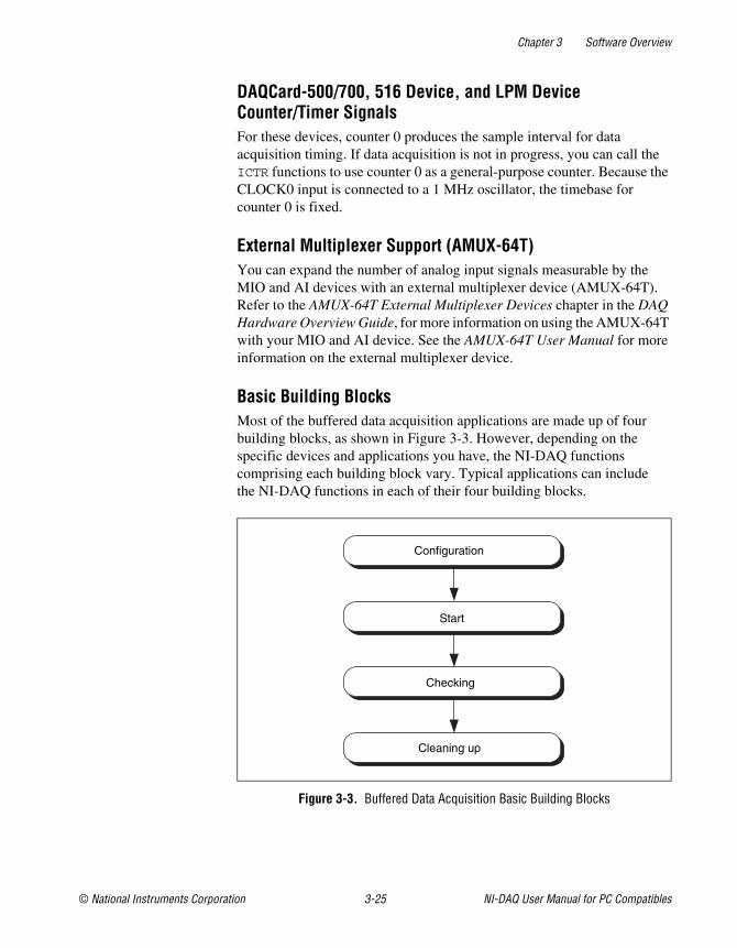
Chapter 3 Software Overview
© National Instruments Corporation 3-25 NI-DAQ User Manual for PC Compatibles
DAQCard-500/700, 516 Device, and LPM DeviceCounter/Timer SignalsFor these devices, counter 0 produces the sample interval for dataacquisition timing. If data acquisition is not in progress, you can call theICTR functions to use counter 0 as a general-purpose counter. Because theCLOCK0 input is connected to a 1 MHz oscillator, the timebase forcounter 0 is fixed.
External Multiplexer Support (AMUX-64T)You can expand the number of analog input signals measurable by theMIO and AI devices with an external multiplexer device (AMUX-64T).Refer to the AMUX-64T External Multiplexer Devices chapter in the DAQHardware Overview Guide, for more information on using the AMUX-64Twith your MIO and AI device. See the AMUX-64T User Manual for moreinformation on the external multiplexer device.
Basic Building BlocksMost of the buffered data acquisition applications are made up of fourbuilding blocks, as shown in Figure 3-3. However, depending on thespecific devices and applications you have, the NI-DAQ functionscomprising each building block vary. Typical applications can includethe NI-DAQ functions in each of their four building blocks.
Figure 3-3. Buffered Data Acquisition Basic Building Blocks
Configuration
Start
Checking
Cleaning up
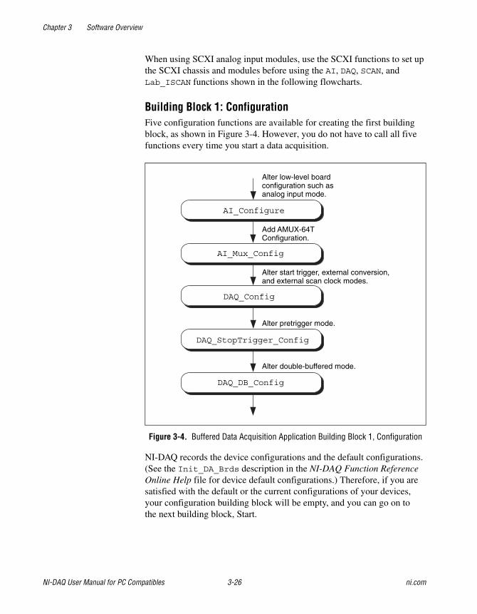
Chapter 3 Software Overview
NI-DAQ User Manual for PC Compatibles 3-26 ni.com
When using SCXI analog input modules, use the SCXI functions to set upthe SCXI chassis and modules before using the AI, DAQ, SCAN, andLab_ISCAN functions shown in the following flowcharts.
Building Block 1: ConfigurationFive configuration functions are available for creating the first buildingblock, as shown in Figure 3-4. However, you do not have to call all fivefunctions every time you start a data acquisition.
Figure 3-4. Buffered Data Acquisition Application Building Block 1, Configuration
NI-DAQ records the device configurations and the default configurations.(See the Init_DA_Brds description in the NI-DAQ Function ReferenceOnline Help file for device default configurations.) Therefore, if you aresatisfied with the default or the current configurations of your devices,your configuration building block will be empty, and you can go on tothe next building block, Start.
DAQ_Config
AI_Mux_Config
AI_Configure
DAQ_DB_Config
DAQ_StopTrigger_Config
Alter double-buffered mode.
Alter pretrigger mode.
Alter start trigger, external conversion,and external scan clock modes.
Add AMUX-64TConfiguration.
Alter low-level boardconfiguration such asanalog input mode.
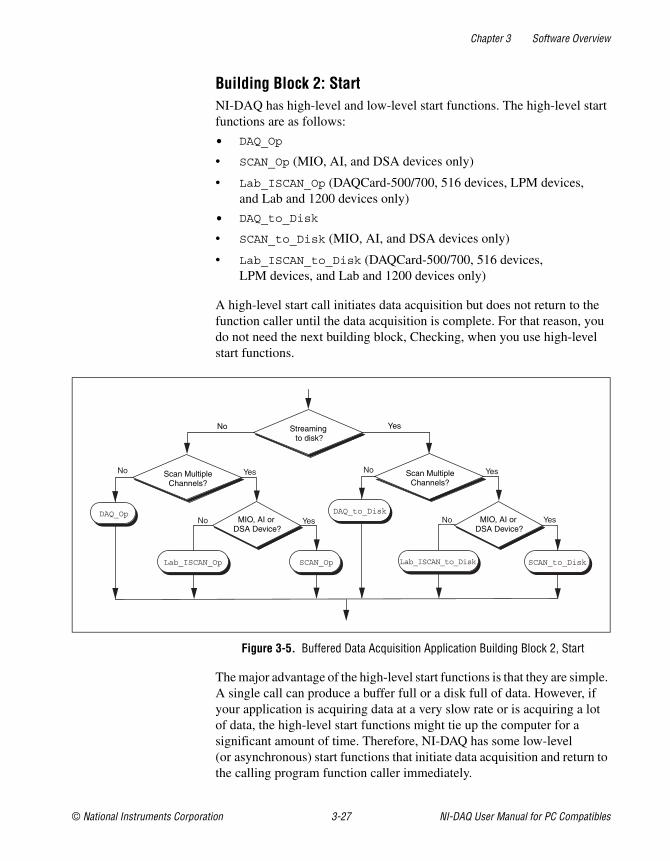
Chapter 3 Software Overview
© National Instruments Corporation 3-27 NI-DAQ User Manual for PC Compatibles
Building Block 2: StartNI-DAQ has high-level and low-level start functions. The high-level startfunctions are as follows:
• DAQ_Op
• SCAN_Op (MIO, AI, and DSA devices only)
• Lab_ISCAN_Op (DAQCard-500/700, 516 devices, LPM devices,and Lab and 1200 devices only)
• DAQ_to_Disk
• SCAN_to_Disk (MIO, AI, and DSA devices only)
• Lab_ISCAN_to_Disk (DAQCard-500/700, 516 devices,LPM devices, and Lab and 1200 devices only)
A high-level start call initiates data acquisition but does not return to thefunction caller until the data acquisition is complete. For that reason, youdo not need the next building block, Checking, when you use high-levelstart functions.
Figure 3-5. Buffered Data Acquisition Application Building Block 2, Start
The major advantage of the high-level start functions is that they are simple.A single call can produce a buffer full or a disk full of data. However, ifyour application is acquiring data at a very slow rate or is acquiring a lotof data, the high-level start functions might tie up the computer for asignificant amount of time. Therefore, NI-DAQ has some low-level(or asynchronous) start functions that initiate data acquisition and return tothe calling program function caller immediately.
No YesStreamingto disk?
Scan MultipleChannels?
DAQ_Op
Lab_ISCAN_Op SCAN_Op
No
No
Yes
Yes
Scan MultipleChannels?
DAQ_to_Disk
Lab_ISCAN_to_Disk SCAN_to_Disk
No
No
Yes
YesMIO, AI orDSA Device?
MIO, AI orDSA Device?
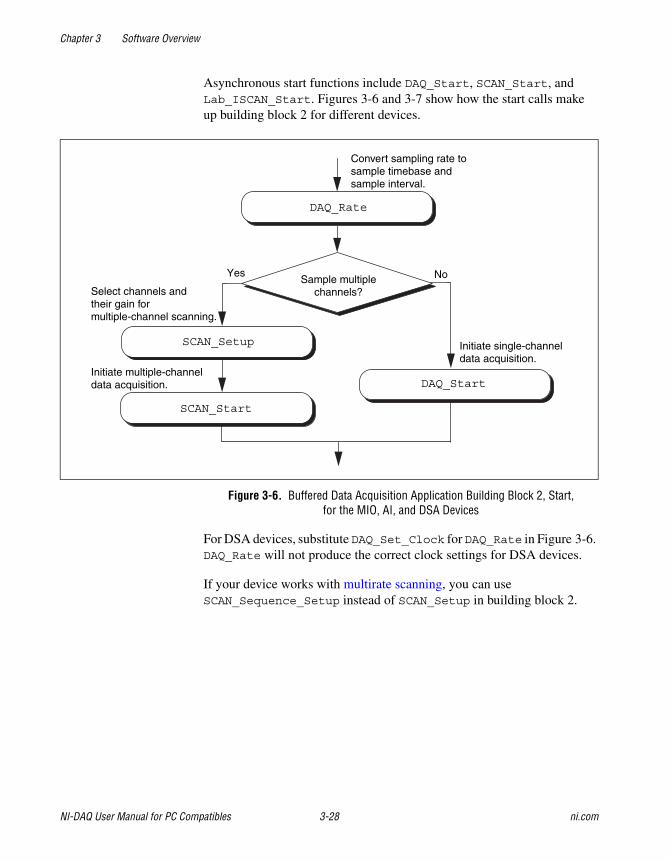
Chapter 3 Software Overview
NI-DAQ User Manual for PC Compatibles 3-28 ni.com
Asynchronous start functions include DAQ_Start, SCAN_Start, andLab_ISCAN_Start. Figures 3-6 and 3-7 show how the start calls makeup building block 2 for different devices.
Figure 3-6. Buffered Data Acquisition Application Building Block 2, Start,for the MIO, AI, and DSA Devices
For DSA devices, substitute DAQ_Set_Clock for DAQ_Rate in Figure 3-6.DAQ_Rate will not produce the correct clock settings for DSA devices.
If your device works with multirate scanning, you can useSCAN_Sequence_Setup instead of SCAN_Setup in building block 2.
DAQ_Rate
Convert sampling rate tosample timebase andsample interval.
SCAN_Setup Initiate single-channeldata acquisition.
No
SCAN_Start
DAQ_StartInitiate multiple-channeldata acquisition.
YesSample multiple
channels?Select channels andtheir gain formultiple-channel scanning.
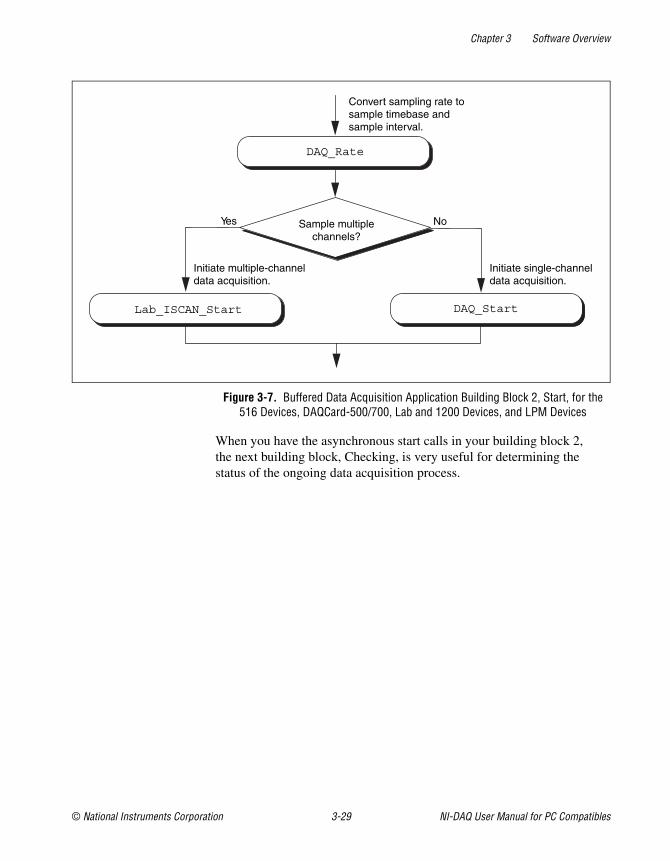
Chapter 3 Software Overview
© National Instruments Corporation 3-29 NI-DAQ User Manual for PC Compatibles
Figure 3-7. Buffered Data Acquisition Application Building Block 2, Start, for the516 Devices, DAQCard-500/700, Lab and 1200 Devices, and LPM Devices
When you have the asynchronous start calls in your building block 2,the next building block, Checking, is very useful for determining thestatus of the ongoing data acquisition process.
DAQ_Rate
Convert sampling rate tosample timebase andsample interval.
Lab_ISCAN_Start
Sample multiplechannels?
NoYes
Initiate multiple-channeldata acquisition.
Initiate single-channeldata acquisition.
DAQ_Start
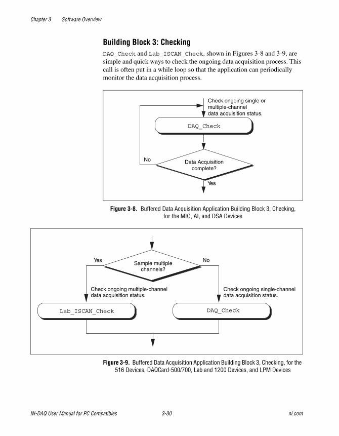
Chapter 3 Software Overview
NI-DAQ User Manual for PC Compatibles 3-30 ni.com
Building Block 3: CheckingDAQ_Check and Lab_ISCAN_Check, shown in Figures 3-8 and 3-9, aresimple and quick ways to check the ongoing data acquisition process. Thiscall is often put in a while loop so that the application can periodicallymonitor the data acquisition process.
Figure 3-8. Buffered Data Acquisition Application Building Block 3, Checking,for the MIO, AI, and DSA Devices
Figure 3-9. Buffered Data Acquisition Application Building Block 3, Checking, for the516 Devices, DAQCard-500/700, Lab and 1200 Devices, and LPM Devices
Check ongoing single ormultiple-channeldata acquisition status.
Data Acquisitioncomplete?
No
Yes
DAQ_Check
Lab_ISCAN_Check
Sample multiplechannels?
NoYes
Check ongoing multiple-channeldata acquisition status.
Check ongoing single-channeldata acquisition status.
DAQ_Check
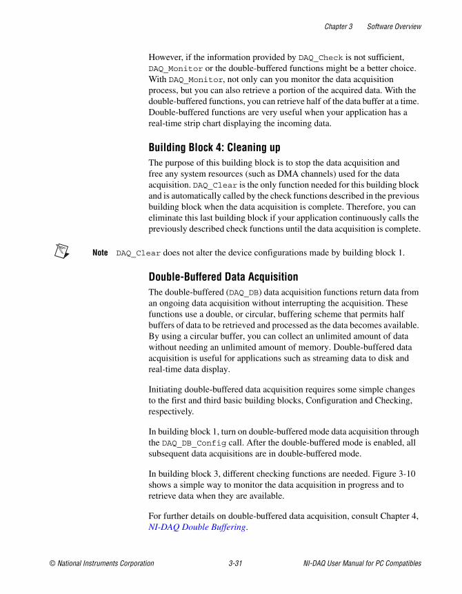
Chapter 3 Software Overview
© National Instruments Corporation 3-31 NI-DAQ User Manual for PC Compatibles
However, if the information provided by DAQ_Check is not sufficient,DAQ_Monitor or the double-buffered functions might be a better choice.With DAQ_Monitor, not only can you monitor the data acquisitionprocess, but you can also retrieve a portion of the acquired data. With thedouble-buffered functions, you can retrieve half of the data buffer at a time.Double-buffered functions are very useful when your application has areal-time strip chart displaying the incoming data.
Building Block 4: Cleaning upThe purpose of this building block is to stop the data acquisition andfree any system resources (such as DMA channels) used for the dataacquisition. DAQ_Clear is the only function needed for this building blockand is automatically called by the check functions described in the previousbuilding block when the data acquisition is complete. Therefore, you caneliminate this last building block if your application continuously calls thepreviously described check functions until the data acquisition is complete.
Note DAQ_Clear does not alter the device configurations made by building block 1.
Double-Buffered Data AcquisitionThe double-buffered (DAQ_DB) data acquisition functions return data froman ongoing data acquisition without interrupting the acquisition. Thesefunctions use a double, or circular, buffering scheme that permits halfbuffers of data to be retrieved and processed as the data becomes available.By using a circular buffer, you can collect an unlimited amount of datawithout needing an unlimited amount of memory. Double-buffered dataacquisition is useful for applications such as streaming data to disk andreal-time data display.
Initiating double-buffered data acquisition requires some simple changesto the first and third basic building blocks, Configuration and Checking,respectively.
In building block 1, turn on double-buffered mode data acquisition throughthe DAQ_DB_Config call. After the double-buffered mode is enabled, allsubsequent data acquisitions are in double-buffered mode.
In building block 3, different checking functions are needed. Figure 3-10shows a simple way to monitor the data acquisition in progress and toretrieve data when they are available.
For further details on double-buffered data acquisition, consult Chapter 4,NI-DAQ Double Buffering.
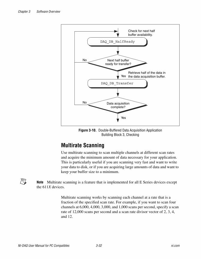
Chapter 3 Software Overview
NI-DAQ User Manual for PC Compatibles 3-32 ni.com
Figure 3-10. Double-Buffered Data Acquisition ApplicationBuilding Block 3, Checking
Multirate ScanningUse multirate scanning to scan multiple channels at different scan ratesand acquire the minimum amount of data necessary for your application.This is particularly useful if you are scanning very fast and want to writeyour data to disk, or if you are acquiring large amounts of data and want tokeep your buffer size to a minimum.
Note Multirate scanning is a feature that is implemented for all E Series devices exceptthe 611X devices.
Multirate scanning works by scanning each channel at a rate that is afraction of the specified scan rate. For example, if you want to scan fourchannels at 6,000, 4,000, 3,000, and 1,000 scans per second, specify a scanrate of 12,000 scans per second and a scan rate divisor vector of 2, 3, 4,and 12.
No
Yes
Yes
No Next half bufferready for transfer?
DAQ_DB_HalfReady
DAQ_DB_Transfer
Data acquisitioncomplete?
Retrieve half of the data inthe data acquisition buffer.
Check for next halfbuffer availability.
Chapter 3 Software Overview
© National Instruments Corporation 3-33 NI-DAQ User Manual for PC Compatibles
NI-DAQ includes three functions for multirate scanning:
• SCAN_Sequence_Setup
• SCAN_Sequence_Retrieve
• SCAN_Sequence_Demux
Use SCAN_Sequence_Setup to identify the channels to scan, theirgains, and their scan rate divisors. After the data is acquired, useSCAN_Sequence_Retrieve and SCAN_Sequence_Demux to arrangethe data into a more convenient format.
Figure 3-11 shows how to use the multirate scanning functions inconjunction with other NI-DAQ functions.
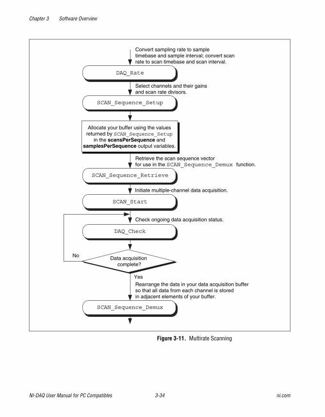
Chapter 3 Software Overview
NI-DAQ User Manual for PC Compatibles 3-34 ni.com
Figure 3-11. Multirate Scanning
Retrieve the scan sequence vectorfor use in the SCAN_Sequence_Demux function.
Allocate your buffer using the valuesreturned by SCAN_Sequence_Setup
in the scansPerSequence andsamplesPerSequence output variables.
DAQ_Rate
SCAN_Sequence_Setup
SCAN_Start
DAQ_Check
SCAN_Sequence_Retrieve
SCAN_Sequence_Demux
Data acquisitioncomplete?
Yes
No
Convert sampling rate to sampletimebase and sample interval; convert scanrate to scan timebase and scan interval.
Select channels and their gainsand scan rate divisors.
Initiate multiple-channel data acquisition.
Check ongoing data acquisition status.
Rearrange the data in your data acquisition bufferso that all data from each channel is storedin adjacent elements of your buffer.
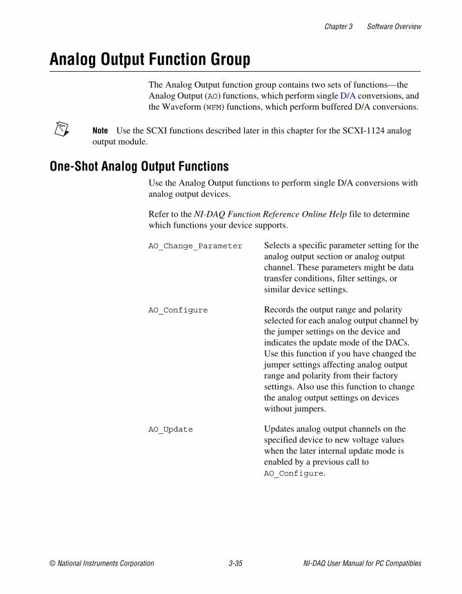
Chapter 3 Software Overview
© National Instruments Corporation 3-35 NI-DAQ User Manual for PC Compatibles
Analog Output Function GroupThe Analog Output function group contains two sets of functions—theAnalog Output (AO) functions, which perform single D/A conversions, andthe Waveform (WFM) functions, which perform buffered D/A conversions.
Note Use the SCXI functions described later in this chapter for the SCXI-1124 analogoutput module.
One-Shot Analog Output FunctionsUse the Analog Output functions to perform single D/A conversions withanalog output devices.
Refer to the NI-DAQ Function Reference Online Help file to determinewhich functions your device supports.
AO_Change_Parameter Selects a specific parameter setting for theanalog output section or analog outputchannel. These parameters might be datatransfer conditions, filter settings, orsimilar device settings.
AO_Configure Records the output range and polarityselected for each analog output channel bythe jumper settings on the device andindicates the update mode of the DACs.Use this function if you have changed thejumper settings affecting analog outputrange and polarity from their factorysettings. Also use this function to changethe analog output settings on deviceswithout jumpers.
AO_Update Updates analog output channels on thespecified device to new voltage valueswhen the later internal update mode isenabled by a previous call toAO_Configure.
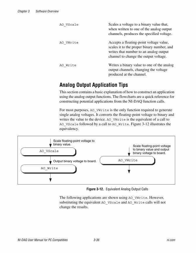
Chapter 3 Software Overview
NI-DAQ User Manual for PC Compatibles 3-36 ni.com
AO_VScale Scales a voltage to a binary value that,when written to one of the analog outputchannels, produces the specified voltage.
AO_VWrite Accepts a floating-point voltage value,scales it to the proper binary number, andwrites that number to an analog outputchannel to change the output voltage.
AO_Write Writes a binary value to one of the analogoutput channels, changing the voltageproduced at the channel.
Analog Output Application TipsThis section contains a basic explanation of how to construct an applicationusing the analog output functions. The flowcharts are a quick reference forconstructing potential applications from the NI-DAQ function calls.
For most purposes, AO_VWrite is the only function required to generatesingle analog voltages. It converts the floating-point voltage to binary andwrites the value to the device. AO_VWrite is the equivalent of a call toAO_VScale followed by a call to AO_Write. Figure 3-12 illustrates theequivalency.
Figure 3-12. Equivalent Analog Output Calls
The following applications are shown using AO_VWrite. However,substituting the equivalent AO_VScale and AO_Write calls will notchange the results.
AO_VWrite
AO_Write
AO_VScale
Scale floating-point voltage tobinary value.
Output binary voltage to board.
Scale floating-point voltageto binary value and outputbinary voltage to board.
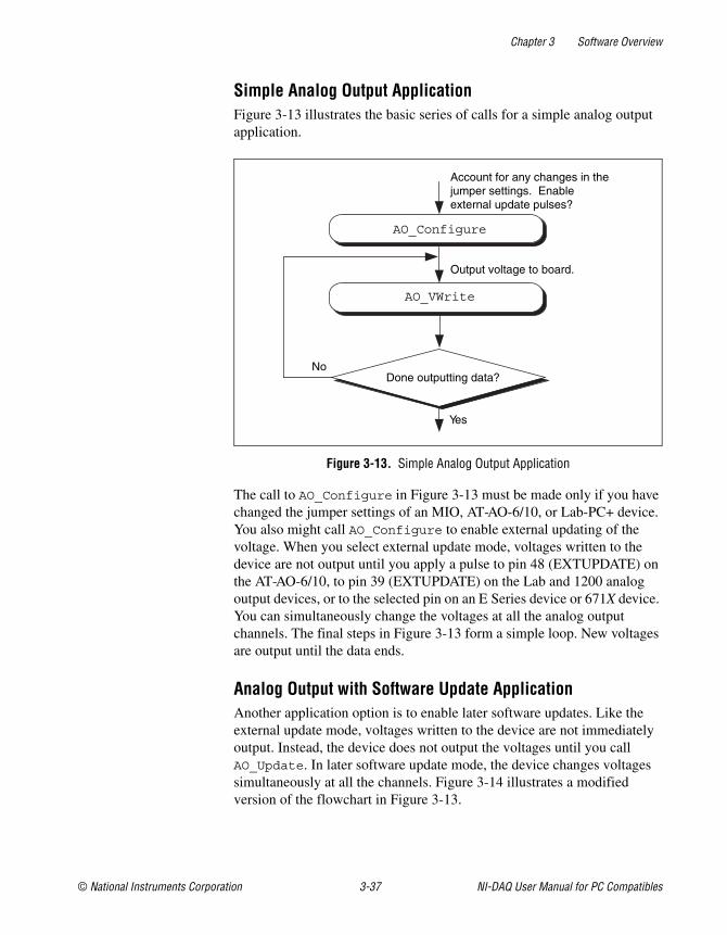
Chapter 3 Software Overview
© National Instruments Corporation 3-37 NI-DAQ User Manual for PC Compatibles
Simple Analog Output ApplicationFigure 3-13 illustrates the basic series of calls for a simple analog outputapplication.
Figure 3-13. Simple Analog Output Application
The call to AO_Configure in Figure 3-13 must be made only if you havechanged the jumper settings of an MIO, AT-AO-6/10, or Lab-PC+ device.You also might call AO_Configure to enable external updating of thevoltage. When you select external update mode, voltages written to thedevice are not output until you apply a pulse to pin 48 (EXTUPDATE) onthe AT-AO-6/10, to pin 39 (EXTUPDATE) on the Lab and 1200 analogoutput devices, or to the selected pin on an E Series device or 671X device.You can simultaneously change the voltages at all the analog outputchannels. The final steps in Figure 3-13 form a simple loop. New voltagesare output until the data ends.
Analog Output with Software Update ApplicationAnother application option is to enable later software updates. Like theexternal update mode, voltages written to the device are not immediatelyoutput. Instead, the device does not output the voltages until you callAO_Update. In later software update mode, the device changes voltagessimultaneously at all the channels. Figure 3-14 illustrates a modifiedversion of the flowchart in Figure 3-13.
No
Yes
Done outputting data?
AO_VWrite
Account for any changes in thejumper settings. Enableexternal update pulses?
Output voltage to board.
AO_Configure
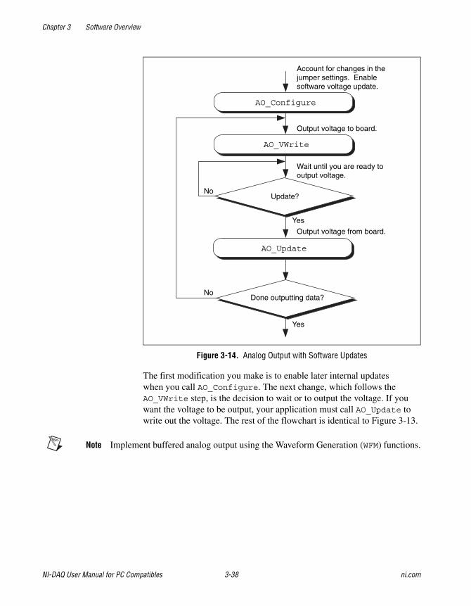
Chapter 3 Software Overview
NI-DAQ User Manual for PC Compatibles 3-38 ni.com
Figure 3-14. Analog Output with Software Updates
The first modification you make is to enable later internal updateswhen you call AO_Configure. The next change, which follows theAO_VWrite step, is the decision to wait or to output the voltage. If youwant the voltage to be output, your application must call AO_Update towrite out the voltage. The rest of the flowchart is identical to Figure 3-13.
Note Implement buffered analog output using the Waveform Generation (WFM) functions.
Update?
AO_VWrite
AO_Update
Done outputting data?
Output voltage from board.
Wait until you are ready tooutput voltage.
Output voltage to board.
Account for changes in thejumper settings. Enablesoftware voltage update.
No
No
Yes
Yes
AO_Configure
Chapter 3 Software Overview
© National Instruments Corporation 3-39 NI-DAQ User Manual for PC Compatibles
Waveform Generation FunctionsUse the Waveform Generation (WFM) functions to perform buffered analogoutput operations with the MIO devices, 671X devices, AT-AO-6/10devices, and Lab and 1200 analog output devices.
Refer to the NI-DAQ Function Reference Online Help file to determinewhich functions your device supports.
High-Level Waveform Generation FunctionsThe following high-level Waveform Generation functions accomplish witha single call tasks that require several low-level calls to accomplish:
WFM_from_Disk Assigns a disk file to one or more analogoutput channels, selects the rate and thenumber of times the data in the file is to begenerated, and starts the generation.WFM_from_Disk always waits forcompletion before returning, unless youcall Timeout_Config.
WFM_Op Assigns a waveform buffer to one or moreanalog output channels, selects the rate andthe number of times the data in the buffer isto be generated, and starts the generation. Ifthe number of buffer generations is finite,WFM_Op waits for completion beforereturning, unless you callTimeout_Config.
Low-Level Waveform Generation FunctionsLow-level Waveform Generation functions are for setting up, starting, andcontrolling synchronous waveform generation operations:
WFM_Chan_Control Temporarily halts or restarts waveformgeneration for a single analog outputchannel.
WFM_Check Returns status information concerning awaveform generation operation.
WFM_ClockRate Sets an update rate and a delay rate for agroup of analog output channels.
Chapter 3 Software Overview
NI-DAQ User Manual for PC Compatibles 3-40 ni.com
WFM_DB_Config Enables and disables the double-bufferedmode of waveform generation.
WFM_DB_HalfReady Checks if the next half buffer for one ormore channels is available for new dataduring a double-buffered waveformgeneration operation. You can useWFM_DB_HalfReady to avoid the waitingperiod possible with the double-bufferedtransfer functions.
WFM_DB_Transfer Transfers new data into one or morewaveform buffers (selected in WFM_Load)as waveform generation is in progress.WFM_DB_Transfer waits until NI-DAQcan transfer the data from the buffer to thewaveform buffer.
WFM_Group_Control Controls waveform generation for a groupof analog output channels.
WFM_Group_Setup Assigns one or more analog outputchannels to a waveform generation group.A call to WFM_Group_Setup is requiredonly for the AT-AO-6/10. By default, allanalog output channels for the Lab and1200 analog output, 671X devices, andMIO devices are in group 1.
WFM_Load Assigns a waveform buffer to one or moreanalog output channels and indicates thenumber of waveform cycles to generate.For the 671X devices, E Series devices, andAT-AO-6/10, this function also enables ordisables FIFO mode waveform generation.
WFM_Rate Converts a waveform generation updaterate into the timebase and update-intervalvalues needed to produce the rate you want.
Chapter 3 Software Overview
© National Instruments Corporation 3-41 NI-DAQ User Manual for PC Compatibles
WFM_Scale Translates an array of floating-point valuesthat represent voltages into an array ofbinary values that produce those voltages.The function uses the current analog outputconfiguration settings to perform theconversions.
WFM_Set_Clock Sets an update rate for a group of channels.
Waveform Generation Application TipsThis section outlines a basic explanation of constructing an applicationwith the Waveform Generation functions. The flowcharts are a quickreference for constructing potential applications from the NI-DAQ functioncalls.
Basic Waveform Generation ApplicationsA basic waveform application outputs a series of voltages to an analogoutput channel. Figure 3-15 illustrates the ordinary series of calls for abasic waveform application.
The first step of Figure 3-15 calls WFM_Scale. The WFM_Scale functionconverts floating-point voltages to integer values, thus producing thevoltages (DAC values) you want.
You have two options available for starting a waveform generation.The first option is to call the high-level function WFM_Op. The WFM_Opfunction immediately begins the waveform generation after you call it.If the number of iterations is nonzero, WFM_Op does not return until thewaveform generation is done and all cleanup work is complete. Settingthe iterations equal to 0 signals NI-DAQ to place the waveform generationin continuous double-buffered mode. In continuous double-buffered mode,waveform generation occurs in the background, and the WFM_Op functionreturns immediately to your application. See the Double-BufferedWaveform Generation Applications section later in this chapter for moreinformation.
The second option to start a waveform generation is to call the followingsequence of functions:
1. WFM_Group_Setup (required only for the AT-AO-6/10) to assign oneor more analog output channels to a group.
2. WFM_Load to assign a waveform buffer to one or more analog outputchannels.
Chapter 3 Software Overview
NI-DAQ User Manual for PC Compatibles 3-42 ni.com
3. WFM_Rate to convert a data output rate to a timebase and an updateinterval that generates the rate you want. WFM_Rate only supportssome devices. Because it does not have a device number parameter,it cannot return an error if you use it with a non-supported device.See the NI-DAQ Function Reference Online Help file for supporteddevices.
4. WFM_ClockRate or WFM_Set_Clock to set the update rate (see theNI-DAQ Function Reference Online Help file to find out whichfunction supports your device).
5. WFM_Group_Control (with operation=START) to start the waveformgeneration in the background and return to your application after thewaveform generation has begun.
The next step in Figure 3-15 shows how the call to WFM_Check.WFM_Check retrieves the current status of the waveform generation. Yourapplication uses this information to determine if the generation is completeor should be stopped.
The final step is to call WFM_Group_Control (operation=CLEAR).The CLEAR operation performs all of the necessary cleanup work after awaveform generation. Additionally, CLEAR halts any ongoing waveformgeneration.
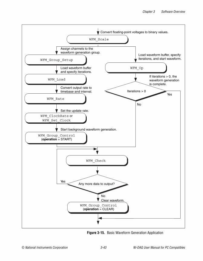
Chapter 3 Software Overview
© National Instruments Corporation 3-43 NI-DAQ User Manual for PC Compatibles
Figure 3-15. Basic Waveform Generation Application
WFM_Load
WFM_Group_Setup
WFM_Group_Control(operation = CLEAR)
WFM_Scale
Iterations > 0
WFM_Op
WFM_Rate
WFM_Group_Control(operation = START)
Convert floating-point voltages to binary values.
Load waveform buffer, specifyiterations, and start waveform.
If iterations > 0, thewaveform generationis complete.
Yes
No
Any more data to output?
No
Yes
Clear waveform.
Start background waveform generation.
Set the update rate.
Convert output rate totimebase and interval.
Load waveform bufferand specify iterations.
Assign channels to thewaveform generation group.
WFM_ClockRate orWFM_Set_Clock
WFM_Check
Chapter 3 Software Overview
NI-DAQ User Manual for PC Compatibles 3-44 ni.com
Basic Waveform Generation with PausesThe application skeleton described in this section is nearly identical tothe basic waveform generation application skeleton. The difference is thatthe description in this section includes the pause and resume operations.Figure 3-16 illustrates the ordinary series of calls for a basic waveformapplication with pauses.
The first step of Figure 3-16 calls WFM_Group_Setup. TheWFM_Group_Setup function assigns one or more analog output channelsto a group.
The second step is to assign a buffer to the analog output channels using thecalls WFM_Scale and WFM_Load. The WFM_Scale function convertsfloating-point voltages to integer values that produce the voltages you want.The WFM_Load function assigns a waveform buffer to one or more analogoutput channels.
The next step is to assign an update rate to the group of channels using thecalls WFM_Rate and WFM_ClockRate. The WFM_Rate function converts adata output rate to a timebase and an update interval that generates the rateyou want. The WFM_ClockRate function assigns a timebase, updateinterval, and delay interval to a group of analog output channels.
Notice that there are restrictions for using the WFM_ClockRate function tospecify delay rate. Refer to the WFM_ClockRate function description in theNI-DAQ Function Reference Online Help file for further details.
Your application is now ready to start a waveform generation. CallWFM_Group_Control (operation=START) to start the waveformgeneration in the background. WFM_Group_Control will return to yourapplication after the waveform generation begins.
The next step in Figure 3-16 is an application decision to pause thewaveform generation. The application uses a number of conditions formaking this decision, including status information returned byWFM_Check.
Pause the waveform generation by calling WFM_Group_Control
(operation=PAUSE). PAUSE stops the waveform generation and maintainsthe current waveform voltage at the channel output.
Chapter 3 Software Overview
© National Instruments Corporation 3-45 NI-DAQ User Manual for PC Compatibles
Resume the waveform generation by calling WFM_Group_Control
(operation=RESUME). RESUME restarts the waveform generation at the datapoint where it was paused. The output rate and the data buffer areunchanged.
The final step is to call WFM_Group_Control (operation=CLEAR).CLEAR performs all the necessary cleanup work after a waveformgeneration. Additionally, CLEAR halts any ongoing waveform generation.
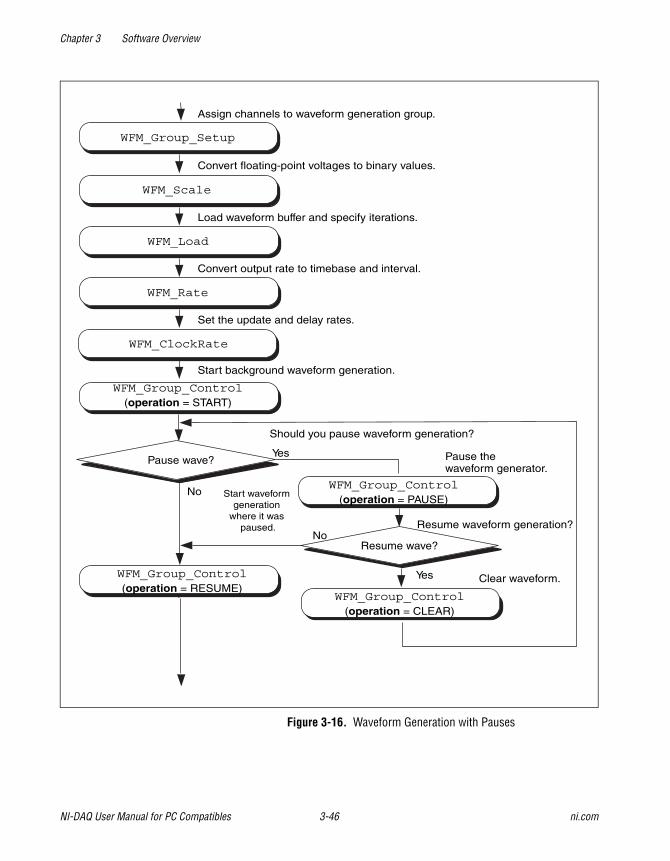
Chapter 3 Software Overview
NI-DAQ User Manual for PC Compatibles 3-46 ni.com
Figure 3-16. Waveform Generation with Pauses
WFM_Group_Control(operation = START)
WFM_ClockRate
Pause wave?
WFM_Group_Control(operation = PAUSE)
WFM_Rate
WFM_Load
Resume wave?
WFM_Scale
WFM_Group_Setup
WFM_Group_Control(operation = RESUME)
WFM_Group_Control(operation = CLEAR)
Assign channels to waveform generation group.
Convert floating-point voltages to binary values.
Load waveform buffer and specify iterations.
Convert output rate to timebase and interval.
Set the update and delay rates.
Start background waveform generation.
Should you pause waveform generation?
Yes
No Start waveformgeneration
where it waspaused.
Pause thewaveform generator.
Resume waveform generation?No
Yes Clear waveform.
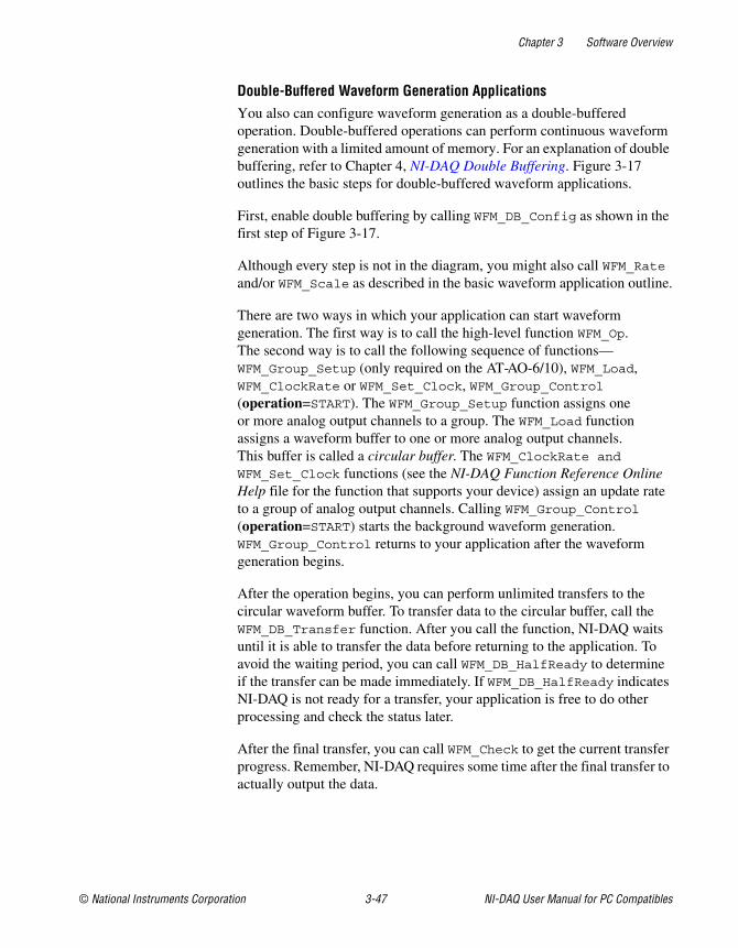
Chapter 3 Software Overview
© National Instruments Corporation 3-47 NI-DAQ User Manual for PC Compatibles
Double-Buffered Waveform Generation ApplicationsYou also can configure waveform generation as a double-bufferedoperation. Double-buffered operations can perform continuous waveformgeneration with a limited amount of memory. For an explanation of doublebuffering, refer to Chapter 4, NI-DAQ Double Buffering. Figure 3-17outlines the basic steps for double-buffered waveform applications.
First, enable double buffering by calling WFM_DB_Config as shown in thefirst step of Figure 3-17.
Although every step is not in the diagram, you might also call WFM_Rateand/or WFM_Scale as described in the basic waveform application outline.
There are two ways in which your application can start waveformgeneration. The first way is to call the high-level function WFM_Op.The second way is to call the following sequence of functions—WFM_Group_Setup (only required on the AT-AO-6/10), WFM_Load,WFM_ClockRate or WFM_Set_Clock, WFM_Group_Control(operation=START). The WFM_Group_Setup function assigns oneor more analog output channels to a group. The WFM_Load functionassigns a waveform buffer to one or more analog output channels.This buffer is called a circular buffer. The WFM_ClockRate and WFM_Set_Clock functions (see the NI-DAQ Function Reference OnlineHelp file for the function that supports your device) assign an update rateto a group of analog output channels. Calling WFM_Group_Control
(operation=START) starts the background waveform generation.WFM_Group_Control returns to your application after the waveformgeneration begins.
After the operation begins, you can perform unlimited transfers to thecircular waveform buffer. To transfer data to the circular buffer, call theWFM_DB_Transfer function. After you call the function, NI-DAQ waitsuntil it is able to transfer the data before returning to the application. Toavoid the waiting period, you can call WFM_DB_HalfReady to determineif the transfer can be made immediately. If WFM_DB_HalfReady indicatesNI-DAQ is not ready for a transfer, your application is free to do otherprocessing and check the status later.
After the final transfer, you can call WFM_Check to get the current transferprogress. Remember, NI-DAQ requires some time after the final transfer toactually output the data.
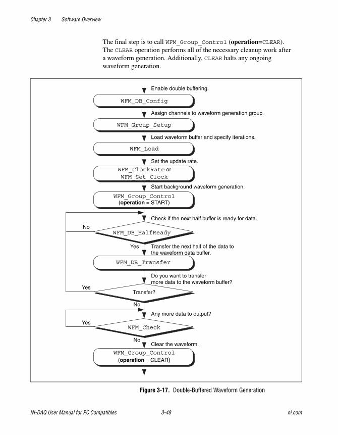
Chapter 3 Software Overview
NI-DAQ User Manual for PC Compatibles 3-48 ni.com
The final step is to call WFM_Group_Control (operation=CLEAR).The CLEAR operation performs all of the necessary cleanup work aftera waveform generation. Additionally, CLEAR halts any ongoingwaveform generation.
Figure 3-17. Double-Buffered Waveform Generation
Enable double buffering.
Assign channels to waveform generation group.
Load waveform buffer and specify iterations.
Set the update rate.
Start background waveform generation.
Check if the next half buffer is ready for data.
Transfer the next half of the data tothe waveform data buffer.
Do you want to transfermore data to the waveform buffer?
Clear the waveform.
WFM_DB_Config
WFM_Group_Setup
WFM_Load
WFM_Group_Control(operation = START)
WFM_DB_HalfReady
WFM_DB_Transfer
Transfer?
WFM_Check
WFM_Group_Control(operation = CLEAR)
No
No
Yes
Yes
Yes
No
Any more data to output?
WFM_ClockRate orWFM_Set_Clock
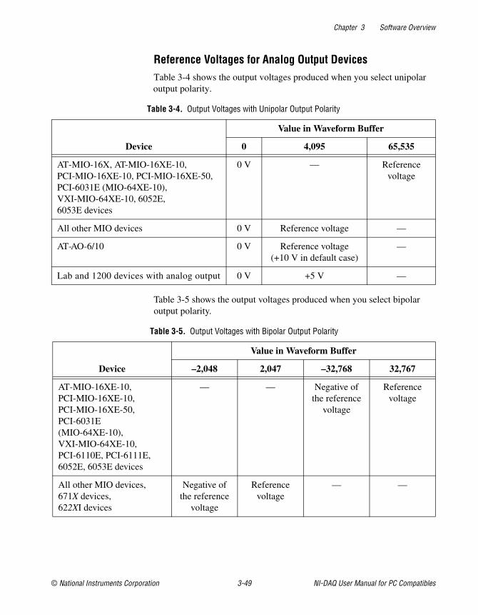
Chapter 3 Software Overview
© National Instruments Corporation 3-49 NI-DAQ User Manual for PC Compatibles
Reference Voltages for Analog Output DevicesTable 3-4 shows the output voltages produced when you select unipolaroutput polarity.
Table 3-5 shows the output voltages produced when you select bipolaroutput polarity.
Table 3-4. Output Voltages with Unipolar Output Polarity
Device
Value in Waveform Buffer
0 4,095 65,535
AT-MIO-16X, AT-MIO-16XE-10,PCI-MIO-16XE-10, PCI-MIO-16XE-50,PCI-6031E (MIO-64XE-10),VXI-MIO-64XE-10, 6052E,6053E devices
0 V — Referencevoltage
All other MIO devices 0 V Reference voltage —
AT-AO-6/10 0 V Reference voltage(+10 V in default case)
—
Lab and 1200 devices with analog output 0 V +5 V —
Table 3-5. Output Voltages with Bipolar Output Polarity
Device
Value in Waveform Buffer
–2,048 2,047 –32,768 32,767
AT-MIO-16XE-10,PCI-MIO-16XE-10,PCI-MIO-16XE-50,PCI-6031E(MIO-64XE-10),VXI-MIO-64XE-10,PCI-6110E, PCI-6111E,6052E, 6053E devices
— — Negative ofthe reference
voltage
Referencevoltage
All other MIO devices,671X devices,622XI devices
Negative ofthe reference
voltage
Referencevoltage
— —
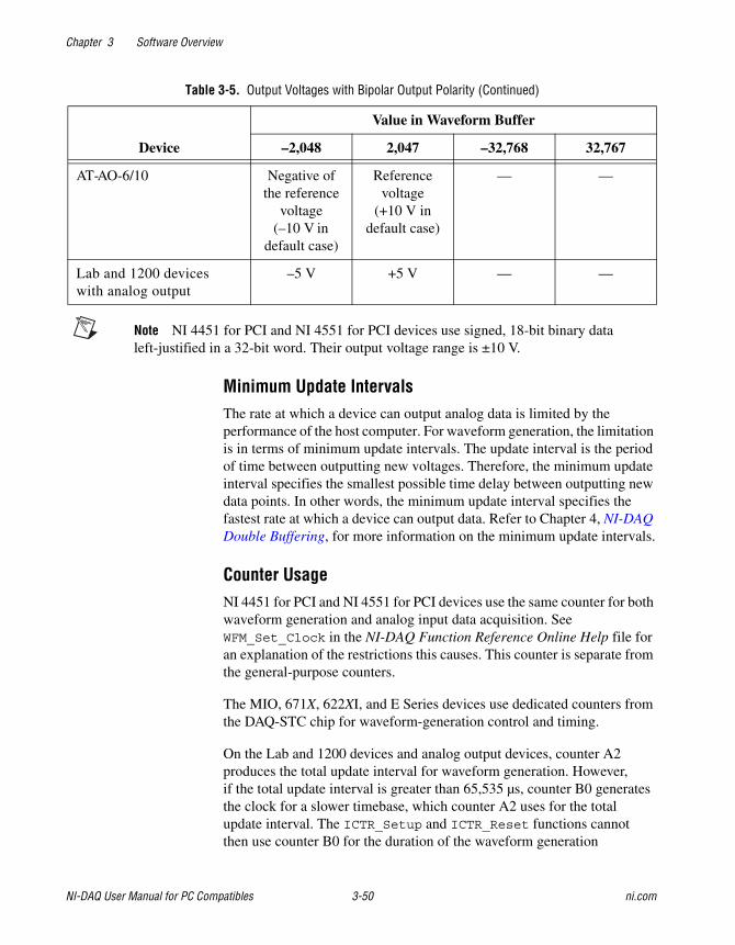
Chapter 3 Software Overview
NI-DAQ User Manual for PC Compatibles 3-50 ni.com
Note NI 4451 for PCI and NI 4551 for PCI devices use signed, 18-bit binary dataleft-justified in a 32-bit word. Their output voltage range is ±10 V.
Minimum Update IntervalsThe rate at which a device can output analog data is limited by theperformance of the host computer. For waveform generation, the limitationis in terms of minimum update intervals. The update interval is the periodof time between outputting new voltages. Therefore, the minimum updateinterval specifies the smallest possible time delay between outputting newdata points. In other words, the minimum update interval specifies thefastest rate at which a device can output data. Refer to Chapter 4, NI-DAQDouble Buffering, for more information on the minimum update intervals.
Counter UsageNI 4451 for PCI and NI 4551 for PCI devices use the same counter for bothwaveform generation and analog input data acquisition. SeeWFM_Set_Clock in the NI-DAQ Function Reference Online Help file foran explanation of the restrictions this causes. This counter is separate fromthe general-purpose counters.
The MIO, 671X, 622XI, and E Series devices use dedicated counters fromthe DAQ-STC chip for waveform-generation control and timing.
On the Lab and 1200 devices and analog output devices, counter A2produces the total update interval for waveform generation. However,if the total update interval is greater than 65,535 µs, counter B0 generatesthe clock for a slower timebase, which counter A2 uses for the totalupdate interval. The ICTR_Setup and ICTR_Reset functions cannotthen use counter B0 for the duration of the waveform generation
AT-AO-6/10 Negative ofthe reference
voltage(–10 V in
default case)
Referencevoltage
(+10 V indefault case)
— —
Lab and 1200 deviceswith analog output
–5 V +5 V — —
Table 3-5. Output Voltages with Bipolar Output Polarity (Continued)
Device
Value in Waveform Buffer
–2,048 2,047 –32,768 32,767
Chapter 3 Software Overview
© National Instruments Corporation 3-51 NI-DAQ User Manual for PC Compatibles
operation. In addition, the data acquisition functions DAQ_Start andLab_ISCAN_Start cannot use counter B0 if the total sample interval fordata acquisition is also greater than 65,535 µs, unless the timebase requiredfor data acquisition is the same as the timebase counter B0 produces forwaveform generation. If data acquisition is not in progress, counter B0 isavailable for waveform generation if ICTR_Setup has not been calledon counter B0 since startup, or an CTR_Reset call has been made oncounter B0. If data acquisition is in progress and is using counter B0to produce the sample timebase, counter B0 is available for waveformgeneration only if this timebase is the same as required by the WaveformGeneration functions to produce the total update interval. In this case,counter B0 produces the same timebase for data acquisition and waveformgeneration.
On the AT-AO-6/10, counter 0 produces the total update interval forgroup 1 waveform generation, and counter 1 produces the total updateinterval for group 2 waveform generation. However, if the total updateinterval is greater than 65,535 µs for either group 1 or 2, counter 2 is usedby counter 0 (group 1) or counter 1 (group 2) to produce the total updateinterval. If either group is using counter 2 to produce the sample timebase,counter 2 is available to the other group only if the timebase is the sameas the timebase required by the Waveform Generation functions to producethe total update interval. In this case, counter 2 produces the same timebasefor both waveform generation groups.
FIFO Lag Effect on the MIO, E Series, AT-AO-6/10,NI 4451 for PCI, NI 4551 for PCI, 622XI, and 671X DevicesGroup 1 analog output channels use an onboard FIFO to output data valuesto the DACs. NI-DAQ continuously writes values to the FIFO as long asthe FIFO is not full. NI-DAQ transfers data values from the FIFO to theDACs at regular intervals using an onboard or external clock. You see a lageffect for group 1 channels because of the FIFO buffering. That is, a valuewritten to the FIFO is not output to the DAC until all of the data valuescurrently in the FIFO have been output to the DACs. This time lag isdependent upon the update rate (specified in WFM_ClockRate). Refer toyour device user manual for a more detailed discussion of theonboard FIFO.
Chapter 3 Software Overview
NI-DAQ User Manual for PC Compatibles 3-52 ni.com
Three functions are affected by the FIFO lag effect—WFM_Chan_Control,WFM_Check, and double-buffered waveform generation.
• WFM_Chan_Control—When you execute operation=PAUSE for agroup 1 channel, the effective pause does not occur until the FIFO hasfinished writing all of the data remaining in the FIFO for the specifiedchannel. The same is true for the RESUME operation on a group 1channel; NI-DAQ cannot place data for the specified channel into theFIFO until the FIFO is empty.
• WFM_Check—The values returned in pointsDone and itersDoneindicate the number of points that NI-DAQ has written to the FIFO forthe specified channel. A time lag occurs from the point when NI-DAQwrites the data to the FIFO when NI-DAQ outputs the data to the DAC.
• When you use double-buffered waveform generation with group 1,make sure the total number of points for all of the group 1 channels(specified in the count parameter in WFM_Load) is at least twice thesize of the FIFO. Refer to your device user manual for information onthe analog output FIFO size.
• For 61XX devices with onboard memory, data is transferredto the memory in blocks of 32 bytes. Therefore, when you usedouble-buffered waveform generation that does not end in a 32-bytesample boundary, the last few points will not be output.
With PCI E Series, 622XI devices, and 671X devices in NI-DAQ 5.1 andlater, you can reduce or even eliminate the FIFO lag effect by specifying theFIFO condition NI-DAQ uses to determine when to put more data into theFIFO. Refer to the AO_Change_Parameter function in NI-DAQ FunctionReference Online Help file for details.
Externally Triggering Your Waveform Generation OperationYou can initiate a waveform generation operation from an externaltrigger signal in much the same manner as for analog input. See theSelect_Signal function in the NI-DAQ Function Reference OnlineHelp file.
Digital I/O Function GroupThe Digital I/O function group contains three sets of functions—the DigitalI/O (DIG) functions, the Group Digital I/O (DIG_Block, DIG_Grp, andDIG_SCAN) functions, and the double-buffered Digital I/O (DIG_DB)functions. Refer to the NI-DAQ Functions Listed by Hardware Product
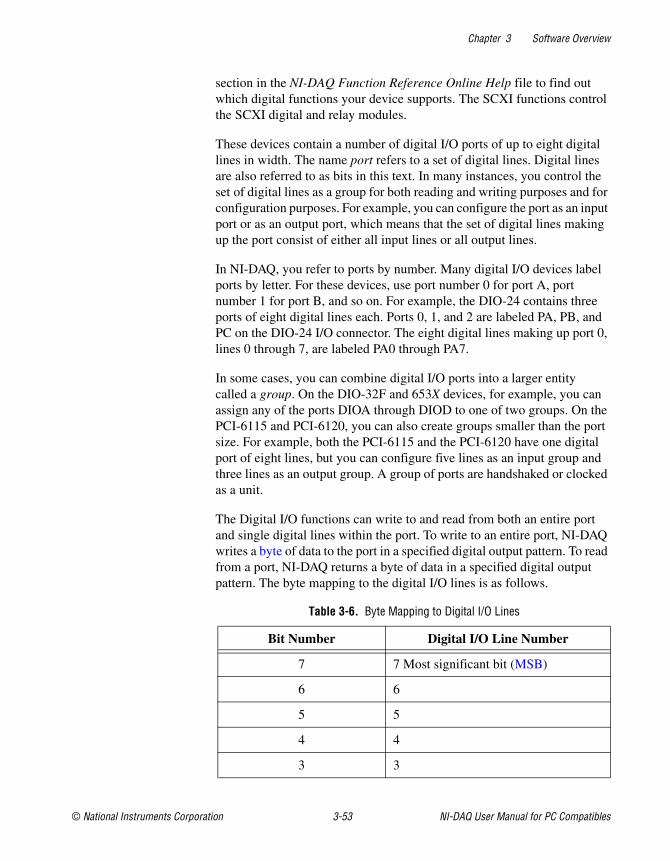
Chapter 3 Software Overview
© National Instruments Corporation 3-53 NI-DAQ User Manual for PC Compatibles
section in the NI-DAQ Function Reference Online Help file to find outwhich digital functions your device supports. The SCXI functions controlthe SCXI digital and relay modules.
These devices contain a number of digital I/O ports of up to eight digitallines in width. The name port refers to a set of digital lines. Digital linesare also referred to as bits in this text. In many instances, you control theset of digital lines as a group for both reading and writing purposes and forconfiguration purposes. For example, you can configure the port as an inputport or as an output port, which means that the set of digital lines makingup the port consist of either all input lines or all output lines.
In NI-DAQ, you refer to ports by number. Many digital I/O devices labelports by letter. For these devices, use port number 0 for port A, portnumber 1 for port B, and so on. For example, the DIO-24 contains threeports of eight digital lines each. Ports 0, 1, and 2 are labeled PA, PB, andPC on the DIO-24 I/O connector. The eight digital lines making up port 0,lines 0 through 7, are labeled PA0 through PA7.
In some cases, you can combine digital I/O ports into a larger entitycalled a group. On the DIO-32F and 653X devices, for example, you canassign any of the ports DIOA through DIOD to one of two groups. On thePCI-6115 and PCI-6120, you can also create groups smaller than the portsize. For example, both the PCI-6115 and the PCI-6120 have one digitalport of eight lines, but you can configure five lines as an input group andthree lines as an output group. A group of ports are handshaked or clockedas a unit.
The Digital I/O functions can write to and read from both an entire portand single digital lines within the port. To write to an entire port, NI-DAQwrites a byte of data to the port in a specified digital output pattern. To readfrom a port, NI-DAQ returns a byte of data in a specified digital outputpattern. The byte mapping to the digital I/O lines is as follows.
Table 3-6. Byte Mapping to Digital I/O Lines
Bit Number Digital I/O Line Number
7 7 Most significant bit (MSB)
6 6
5 5
4 4
3 3
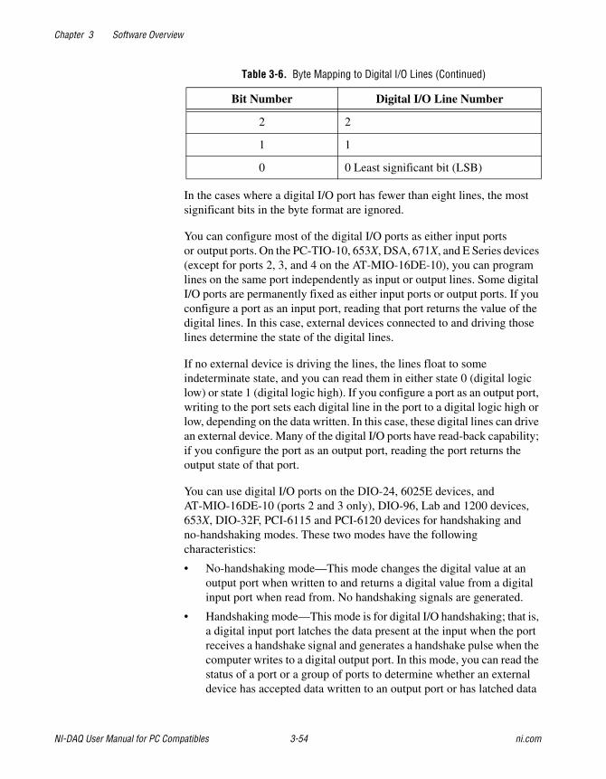
Chapter 3 Software Overview
NI-DAQ User Manual for PC Compatibles 3-54 ni.com
In the cases where a digital I/O port has fewer than eight lines, the mostsignificant bits in the byte format are ignored.
You can configure most of the digital I/O ports as either input portsor output ports. On the PC-TIO-10, 653X, DSA, 671X, and E Series devices(except for ports 2, 3, and 4 on the AT-MIO-16DE-10), you can programlines on the same port independently as input or output lines. Some digitalI/O ports are permanently fixed as either input ports or output ports. If youconfigure a port as an input port, reading that port returns the value of thedigital lines. In this case, external devices connected to and driving thoselines determine the state of the digital lines.
If no external device is driving the lines, the lines float to someindeterminate state, and you can read them in either state 0 (digital logiclow) or state 1 (digital logic high). If you configure a port as an output port,writing to the port sets each digital line in the port to a digital logic high orlow, depending on the data written. In this case, these digital lines can drivean external device. Many of the digital I/O ports have read-back capability;if you configure the port as an output port, reading the port returns theoutput state of that port.
You can use digital I/O ports on the DIO-24, 6025E devices, andAT-MIO-16DE-10 (ports 2 and 3 only), DIO-96, Lab and 1200 devices,653X, DIO-32F, PCI-6115 and PCI-6120 devices for handshaking andno-handshaking modes. These two modes have the followingcharacteristics:
• No-handshaking mode—This mode changes the digital value at anoutput port when written to and returns a digital value from a digitalinput port when read from. No handshaking signals are generated.
• Handshaking mode—This mode is for digital I/O handshaking; that is,a digital input port latches the data present at the input when the portreceives a handshake signal and generates a handshake pulse when thecomputer writes to a digital output port. In this mode, you can read thestatus of a port or a group of ports to determine whether an externaldevice has accepted data written to an output port or has latched data
2 2
1 1
0 0 Least significant bit (LSB)
Table 3-6. Byte Mapping to Digital I/O Lines (Continued)
Bit Number Digital I/O Line Number
Chapter 3 Software Overview
© National Instruments Corporation 3-55 NI-DAQ User Manual for PC Compatibles
into an input port. The handshaking mode for the PCI 6115 and thePCI-6120 is slightly different and is more appropriately called aclocking mode. In the clocking mode, no two-way handshaking signalsare generated. Instead, data is latched in or latched out when a pulsefrom a clock signal is detected.
Note On the 653X, DIO-32F, PCI-6115, and PCI-6120 devices, you must assign ports toa group before you can use handshaking mode.
Process control applications, such as controlling or monitoring relays,often use the no-handshaking mode. Communications applications, such astransferring data between two computers, often use the handshaking mode.
DIO-24, 6025E, AT-MIO-16DE-10, DIO-96, and Lab and1200 Device Groups
You can group together any combination of ports 0, 1, 3, 4, 6, 7, 9, and 10on the DIO-96, ports 0 and 1 on the DIO-24 and Lab and 1200 devices,and ports 2 and 3 on the 6025E devices and AT-MIO-16DE-10 to make uplarger ports. For example, with the DIO-96 you can program ports 0, 3, 9,and 10 to make up a 32-bit handshaking port, or program all eight ports tomake up a 64-bit handshaking port. See Digital I/O Application Tips laterin this chapter and the DIG_SCAN_Setup function description in theNI-DAQ Function Reference Online Help file for more details.
DIO-32F and 653X Device GroupsOn the DIO-32F and 653X devices, you can assign ports 0 through 3(referring to ports DIOA through DIOD) to one of two groups forhandshaking. These groups are referred to as group 1 and group 2. Group 1uses handshake lines REQ1 and ACK1. Group 2 uses handshake linesREQ2 and ACK2. The group senses the REQ line. An active REQ signal isan indication that the group must perform a read or write. The group drivesthe ACK line. After the group has performed a read or write, it drives theACK line to its active state. Refer to your device user manual for moreinformation on the handshaking signals.
A group can be 8, 16, or 32 bits wide. An 8-bit group can be port 0, 1, 2,or 3. A 16-bit group can be ports 0 and 1 or ports 2 and 3. A 32-bit groupis all four ports.
After you have assigned ports to a group, the group acts as a single entitycontrolling 8, 16, or 32 digital lines simultaneously. The DIO-32F has
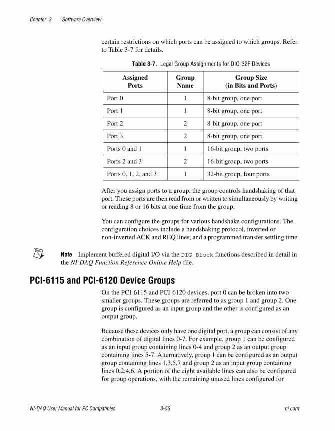
Chapter 3 Software Overview
NI-DAQ User Manual for PC Compatibles 3-56 ni.com
certain restrictions on which ports can be assigned to which groups. Referto Table 3-7 for details.
After you assign ports to a group, the group controls handshaking of thatport. These ports are then read from or written to simultaneously by writingor reading 8 or 16 bits at one time from the group.
You can configure the groups for various handshake configurations. Theconfiguration choices include a handshaking protocol, inverted ornon-inverted ACK and REQ lines, and a programmed transfer settling time.
Note Implement buffered digital I/O via the DIG_Block functions described in detail inthe NI-DAQ Function Reference Online Help file.
PCI-6115 and PCI-6120 Device GroupsOn the PCI-6115 and PCI-6120 devices, port 0 can be broken into twosmaller groups. These groups are referred to as group 1 and group 2. Onegroup is configured as an input group and the other is configured as anoutput group.
Because these devices only have one digital port, a group can consist of anycombination of digital lines 0-7. For example, group 1 can be configuredas an input group containing lines 0-4 and group 2 as an output groupcontaining lines 5-7. Alternatively, group 1 can be configured as an outputgroup containing lines 1,3,5,7 and group 2 as an input group containinglines 0,2,4,6. A portion of the eight available lines can also be configuredfor group operations, with the remaining unused lines configured for
Table 3-7. Legal Group Assignments for DIO-32F Devices
AssignedPorts
GroupName
Group Size(in Bits and Ports)
Port 0 1 8-bit group, one port
Port 1 1 8-bit group, one port
Port 2 2 8-bit group, one port
Port 3 2 8-bit group, one port
Ports 0 and 1 1 16-bit group, two ports
Ports 2 and 3 2 16-bit group, two ports
Ports 0, 1, 2, and 3 1 32-bit group, four ports
Chapter 3 Software Overview
© National Instruments Corporation 3-57 NI-DAQ User Manual for PC Compatibles
immediate digital operations. However, both groups cannot be configuredfor input or output at the same time.
Although a group can consist of non-contiguous lines, there is no logicalgrouping of the lines, and an 8-bit value is still passed from the inputfunction or returned from the output function. For example, if a group isconfigured for output with lines 0,1,2,4, and the group is to be written withall ones, the hex value of 0x17 is passed to the function instead of 0xF.
Group operations are buffered operations only, which means immediatedigital operations are not possible with these devices using handshaking.Because all group operations are buffered, there is no support for a statusoperation indicating when an input operation has been latched to or anoutput operation latched from the digital lines. Instead, group operationsare done from a buffer. In the case of digital output operations, values arewritten to a buffer and latched onto the digital lines when the appropriateedge from a clock signal is detected. For digital input operations, values arelatched from the digital lines to the buffer when the appropriate edge of theclock signal is detected. Either a rising edge or a falling edge of the clocksignal can be specified for latching the values. The clock source can be atiming signal used internally or generated external to the board, and it mustbe routed to one of the RTSI lines.
Digital I/O FunctionsThe digital I/O (DIG) functions perform nonhandshaked digital line andport I/O.
Refer to the NI-DAQ Function Reference Online Help file to determinewhich functions your device supports.
DIG_In_Line Returns the digital logic state of thespecified digital input line in thespecified port.
DIG_In_Prt Returns digital input data from thespecified digital I/O port.
DIG_Line_Config Configures the specified line on a specifiedport for direction (input or output).
DIG_Out_Line Sets or clears the specified digital outputline in the specified digital port.
Chapter 3 Software Overview
NI-DAQ User Manual for PC Compatibles 3-58 ni.com
DIG_Out_Prt Writes digital output data to the specifieddigital port.
DIG_Prt_Config Configures the specified port for direction(input or output).
DIG_Prt_Status Returns a status word indicatingthe handshake status of the specified port.
Group Digital I/O FunctionsThe Group Digital I/O (DIG_Block, DIG_Grp, and DIG_SCAN) functionsperform handshaked I/O on groups of ports.
Refer to the NI-DAQ Function Reference Online Help file to determinewhich functions your device supports.
DIG_Block_Check Returns the number of items remaining tobe transferred after a DIG_Block_In orDIG_Block_Out call.
DIG_Block_Clear Halts any ongoing asynchronous transfer,allowing another transfer to be initiated.
DIG_Block_In Initiates an asynchronous data transferfrom the specified group to memory.
DIG_Block_Out Initiates an asynchronous data transferfrom memory to the specified group.
DIG_Block_PG_Config Enables or disables the pattern generationmode of buffered digital I/O.
DIG_Grp_Config Configures the specified group for portassignment, direction (input or output),and size.
DIG_Grp_Mode Configures the specified group forhandshake signal modes.
DIG_Grp_Status Returns a status word indicating thehandshake status of the specified group.
DIG_In_Grp Reads digital input data from the specifieddigital group.
Chapter 3 Software Overview
© National Instruments Corporation 3-59 NI-DAQ User Manual for PC Compatibles
DIG_Out_Grp Writes digital output data to the specifieddigital group.
DIG_SCAN_Setup Configures the specified group for portassignment, direction (input or output),and size.
DIG_Trigger_Config Enables or disables the trigger mode ofbuffered digital I/O to indicate when tostart and stop the data acquisition.
Double-Buffered Digital I/O FunctionsThe double-buffered digital I/O (DIG_DB) functions performdouble-buffered operations during Group Digital I/O operations.
Refer to the NI-DAQ Function Reference Online Help file to determinewhich functions your device supports.
DIG_DB_Config Enables or disables double-buffereddigital transfer operations and sets thedouble-buffered options.
DIG_DB_HalfReady Checks whether the next half buffer of datais available during a double-buffereddigital block operation. You can useDIG_DB_HalfReady to avoid the possiblewaiting period that can occur becauseDIG_DB_Transfer waits until the datacan be transferred before returning.
DIG_DB_Transfer For an input operation,DIG_DB_Transfer waits until NI-DAQcan transfer half the data from the bufferbeing used for double-buffered digitalblock input to another buffer, which ispassed to the function. For an outputoperation, DIG_DB_Transfer waitsuntil NI-DAQ can transfer the data fromthe buffer passed to the function to thebuffer being used for double-buffereddigital block output. You can executeDIG_DB_Transfer repeatedly to reador write sequential half buffers of data.
Chapter 3 Software Overview
NI-DAQ User Manual for PC Compatibles 3-60 ni.com
Digital Change Notification FunctionsThe Digital Change Notification functions provide messaging for linesand ports on the 652X devices. For other boards such as the DIO-24, theConfig_DAQ_Event_Message function handles event messaging.
DIG_Change_Message_Config
Configures 652X devices to detect rising orfalling edges on input lines and to notifyyou by generating a message.
DIG_Change_Message_ControlControls the change notification operationof the digital input lines on 652X devices.
Digital Filtering FunctionThe Digital Filtering function provides signal conditioning to filter theinputs of 652X devices.
DIG_Filter_Config Configures filtering for the input lines on652X devices.
Digital Change Notification Applications with652X DevicesDigital change notification applications automatically detect changes oninput lines and notify you or your software by message. These applicationsmay use digital filtering to eliminate signals that may trigger unwantedchange notification. Digital filtering can be used alone to condition anddebounce input data.
Figure 3-18 illustrates the series of calls needed for change notification onthe input data. Figure 3-19 illustrates the series of calls needed for filteringthe input data without change notification. Only 652X devices can executechange notification and filtering applications using these functions.
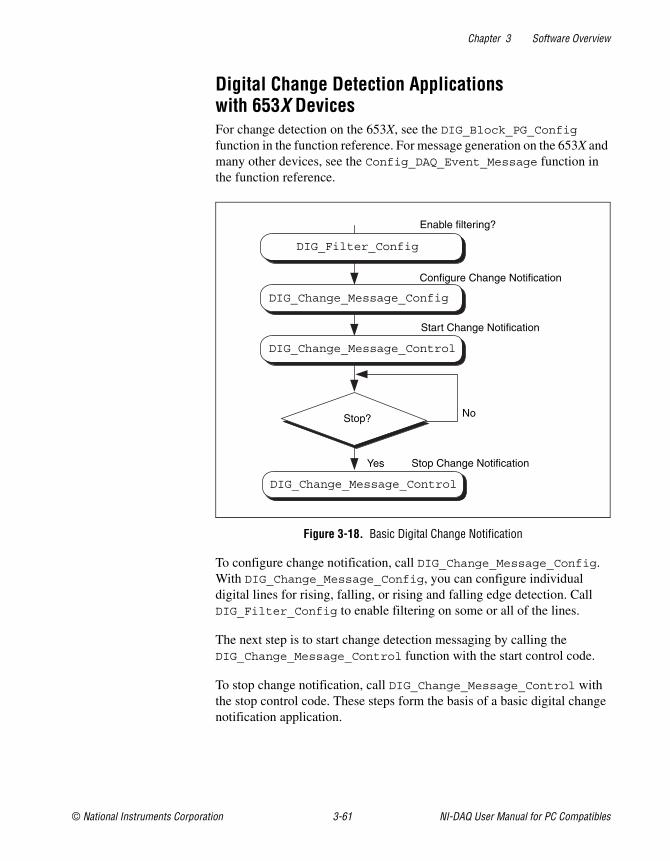
Chapter 3 Software Overview
© National Instruments Corporation 3-61 NI-DAQ User Manual for PC Compatibles
Digital Change Detection Applicationswith 653X DevicesFor change detection on the 653X, see the DIG_Block_PG_Configfunction in the function reference. For message generation on the 653X andmany other devices, see the Config_DAQ_Event_Message function inthe function reference.
Figure 3-18. Basic Digital Change Notification
To configure change notification, call DIG_Change_Message_Config.With DIG_Change_Message_Config, you can configure individualdigital lines for rising, falling, or rising and falling edge detection. CallDIG_Filter_Config to enable filtering on some or all of the lines.
The next step is to start change detection messaging by calling theDIG_Change_Message_Control function with the start control code.
To stop change notification, call DIG_Change_Message_Control withthe stop control code. These steps form the basis of a basic digital changenotification application.
Enable filtering?
Yes
No
Configure Change Notification
Stop?
DIG_Change_Message_Control
DIG_Change_Message_Control
DIG_Change_Message_Config
DIG_Filter_Config
Stop Change Notification
Start Change Notification
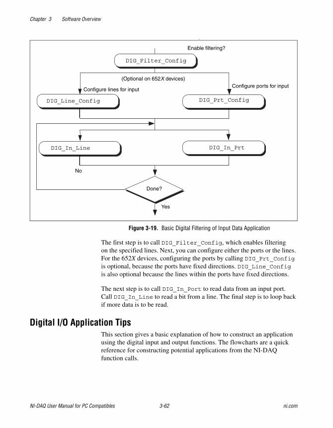
Chapter 3 Software Overview
NI-DAQ User Manual for PC Compatibles 3-62 ni.com
F
Figure 3-19. Basic Digital Filtering of Input Data Application
The first step is to call DIG_Filter_Config, which enables filteringon the specified lines. Next, you can configure either the ports or the lines.For the 652X devices, configuring the ports by calling DIG_Prt_Config
is optional, because the ports have fixed directions. DIG_Line_Configis also optional because the lines within the ports have fixed directions.
The next step is to call DIG_In_Port to read data from an input port.Call DIG_In_Line to read a bit from a line. The final step is to loop backif more data is to be read.
Digital I/O Application TipsThis section gives a basic explanation of how to construct an applicationusing the digital input and output functions. The flowcharts are a quickreference for constructing potential applications from the NI-DAQfunction calls.
Enable filtering?
Yes
No
Configure lines for input
Done?
DIG_Line_Config
(Optional on 652X devices)Configure ports for input
DIG_Prt_Config
DIG_In_Line DIG_In_Prt
DIG_Filter_Config
Chapter 3 Software Overview
© National Instruments Corporation 3-63 NI-DAQ User Manual for PC Compatibles
Handshaking Versus No-Handshaking Digital I/ODigital ports can output or input digital data in two ways. The first is toimmediately read or write data to or from the port. This type of digital I/Ois called no-handshaking mode. The second method is to coordinate digitaldata transfers with another digital port. The second method is called digitalI/O with handshaking. With handshaking, you use dedicated transmissionlines to ensure that data on the receiving end is not overwritten with newdata before it is read from the input port.
NI-DAQ supports both handshaking and no-handshaking modes. Theapplication outlines within this section explain the use of both modeswhere they apply.
Digital Port I/O ApplicationsDigital port I/O applications use individual digital ports to input or outputdigital data. In addition, the applications input or output data points onan individual basis.
You can configure individual port transfers for handshaking orno-handshaking. All AT and PC devices with digital I/O ports canuse no-handshaking digital port I/O. DIO-24, 6025E devices,AT-MIO-16DE-10, DIO-96, and Lab and 1200 devices can alsoexecute handshaking digital I/O for using the port I/O functions.
Figure 3-20 illustrates the series of calls for digital port I/O applicationswith handshaking. Figure 3-21 illustrates the series of calls for digital portI/O applications without handshaking.

Chapter 3 Software Overview
NI-DAQ User Manual for PC Compatibles 3-64 ni.com
Figure 3-20. Basic Port Input or Output Application with Handshaking
Figure 3-21. Basic Port Input or Output Application without Handshaking
Configure ports for input oroutput. Enable optional handshaking?
Check for port ready ifhandshaking is enabled.
DIG_Prt_Config
DIG_Prt_Status
DIG_Out_PrtDIG_In_Prt
Done?No
Yes
Ready
Not Ready
Output data to port.Input data from port.
Done?
DIG_Out_Prt
DIG_Prt_Config
Output data to port.Input data from port.
DIG_In_Prt
Yes
No
Chapter 3 Software Overview
© National Instruments Corporation 3-65 NI-DAQ User Manual for PC Compatibles
The first step is to call DIG_Prt_Config, with which you configurethe individual digital ports for input or output and enable handshaking.
If handshaking is disabled, do not check the port status (step 2 ofFigure 3-21). If handshaking is enabled, call DIG_PRT_Status todetermine if an output port is ready to output a new data point, or if an inputport has latched new data.
The third step is to input or output the data point. Call DIG_In_Prt to readdata from an input port. Call DIG_Out_Prt to write data to an output port.
The final step is to loop back if more data is to be input or output. Thesefour steps form the basis of a simple digital port I/O application.
Digital Line I/O ApplicationsDigital line I/O applications are similar to digital port I/O applications,except that digital line I/O applications input or output data on a bit-by-bitbasis rather than by port. The digital line I/O can only transfer data inno-handshaking mode.

Chapter 3 Software Overview
NI-DAQ User Manual for PC Compatibles 3-66 ni.com
Figure 3-22 is a flowchart outlining the basic line I/O application.
Figure 3-22. Basic Line Input or Output Application
First, configure the digital lines for input or output. You can program653X devices, PC-TIO-10, PCI-6703, PCI-6704, PXI-6703, PXI-6704,622XI, 671X, and E Series devices on an individual line basis. To dothis, call DIG_Line_Config. You must configure all other devices ona port-by-port basis. As a result, you must configure all lines within a portfor the same direction. Call DIG_Prt_Config to configure a port for inputor output. For the 652X devices it is not necessary to configure a port orline since the line direction is preconfigured.
The next step is to call DIG_In_Line or DIG_Out_Line to output or inputa bit from or to the line. The final step is to loop back until NI-DAQ hastransferred all of the data.
Done?
DIG_Out_Line
DIG_Line_Config DIG_Prt_Config
Output data to line.
Configure ports for input or output.Configure lines for input or output.
Input data from line.
DIG_In_Line
Yes
No
Yes No
TIO, DSA, 62XX, 652X,PCI/PXI–6703/6704, DIO 6533 (DIO-32HS),
VXI-AO-48XDC, or E Seriesdevice?
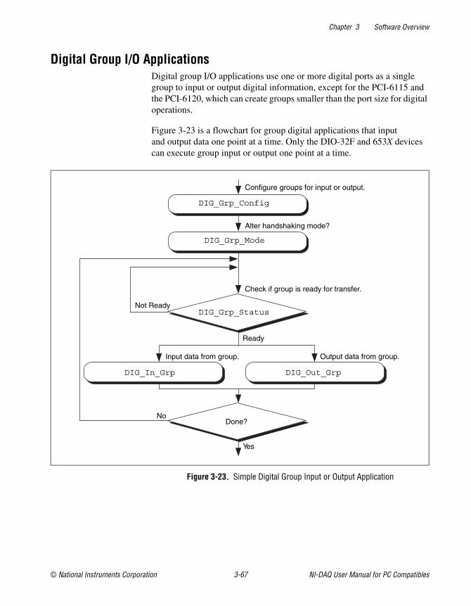
Chapter 3 Software Overview
© National Instruments Corporation 3-67 NI-DAQ User Manual for PC Compatibles
Digital Group I/O ApplicationsDigital group I/O applications use one or more digital ports as a singlegroup to input or output digital information, except for the PCI-6115 andthe PCI-6120, which can create groups smaller than the port size for digitaloperations.
Figure 3-23 is a flowchart for group digital applications that inputand output data one point at a time. Only the DIO-32F and 653X devicescan execute group input or output one point at a time.
Figure 3-23. Simple Digital Group Input or Output Application
No
Yes
Done?
DIG_Out_Grp
DIG_Grp_Mode
DIG_Grp_Config
Output data from group.Input data from group.
DIG_In_Grp
DIG_Grp_StatusNot Ready
Ready
Check if group is ready for transfer.
Alter handshaking mode?
Configure groups for input or output.
Chapter 3 Software Overview
NI-DAQ User Manual for PC Compatibles 3-68 ni.com
At the start of your application, call DIG_Grp_Config to configurethe individual digital ports as a group. After the ports are grouped, callDIG_Grp_Mode (step 2 of Figure 3-23) to alter the handshaking mode ofthe DIO-32F and 653X devices. The various handshaking modes and thedefault settings are explained in the DIG_Grp_Mode function description.
The next step in your application is to check if the port is ready for a transfer(step 3 of Figure 3-23). To do this, call DIG_Grp_Status. If the groupstatus indicates it is ready, call DIG_Out_Grp or DIG_In_Grp to transferthe data to or from the group.
The final step of the flowchart is to loop back until all of the data has beeninput or output.
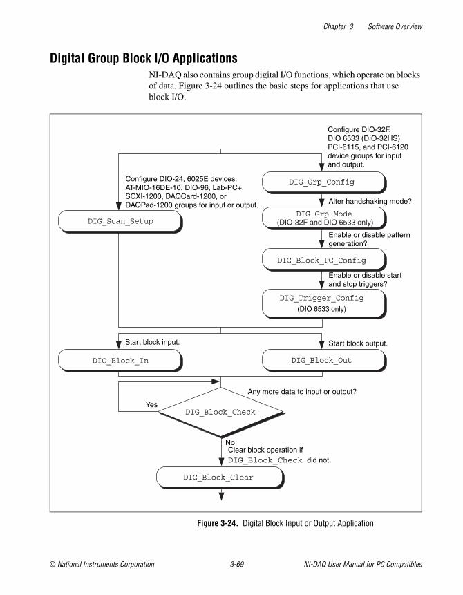
Chapter 3 Software Overview
© National Instruments Corporation 3-69 NI-DAQ User Manual for PC Compatibles
Digital Group Block I/O ApplicationsNI-DAQ also contains group digital I/O functions, which operate on blocksof data. Figure 3-24 outlines the basic steps for applications that useblock I/O.
Figure 3-24. Digital Block Input or Output Application
DIG_Block_PG_Config
DIG_Grp_Mode
DIG_Grp_Config
DIG_Scan_Setup
DIG_Block_In DIG_Block_Out
DIG_Block_Check
DIG_Block_Clear
Configure DIO-32F,DIO 6533 (DIO-32HS),PCI-6115, and PCI-6120device groups for inputand output.
Alter handshaking mode?
Enable or disable patterngeneration?
Enable or disable startand stop triggers?
Start block output.
Any more data to input or output?
Clear block operation ifDIG_Block_Check did not.
No
Yes
Start block input.
Configure DIO-24, 6025E devices,AT-MIO-16DE-10, DIO-96, Lab-PC+,SCXI-1200, DAQCard-1200, orDAQPad-1200 groups for input or output.
DIG_Trigger_Config
(DIO 6533 only)
(DIO-32F and DIO 6533 only)
Chapter 3 Software Overview
NI-DAQ User Manual for PC Compatibles 3-70 ni.com
Note The DIO-32F, 653X, DIO-24, 6025E devices, AT-MIO-16DE-10, DIO-96, and Laband 1200 devices all can perform group block operations. However, the DIO-24, 6025Edevices, AT-MIO-16DE-10, DIO-96, and Lab and 1200 devices have special wiringrequirements for groups larger than one port. The wiring for both the input and output casesfor these devices is explained in the DIG_SCAN_Setup function description. No additionalwiring is necessary for the DIO-32F and 653X devices.
The first step for a group block I/O application is to call DIG_Grp_Configor DIG_SCAN_Setup to configure individual ports as a group. CallDIG_Grp_Config if you have a DIO-32F, 653X, PCI-6115, or a PCI-6120device. Call DIG_SCAN_Setup for all other devices. The DIO-32F isrestricted to group sizes of two and four ports for block I/O.
If you are using a DIO-32F or 653X device, you can alter the handshakingmode of the group by calling DIG_Grp_Mode. For the DIO-32F, 653X,PCI-6115, and PCI-6120, you can perform digital pattern generation bycalling DIG_Block_PG_Config, as shown in Figure 3-24. Patterngeneration is simply reading in or writing out digital data at a fixed rate.This is the digital equivalent of analog waveform generation. To enablepattern generation, call DIG_Block_PG_Config as shown in Figure 3-24.You cannot handshake with pattern generation, so do not connect anyhandshaking lines. Refer to the explanation of pattern generation laterin this chapter for more information.
The next step for your application, as illustrated in Figure , is to callDIG_Block_In or DIG_Block_Out to start the data transfer.
After you start the operation, you can call DIG_Block_Check to get thecurrent progress of the transfer. If the block operation completes prior toa DIG_Block_Check call, DIG_Block_Check automatically callsDIG_Block_Clear, which performs cleanup work.
The final step of a digital block operation is to call DIG_Block_Clear.DIG_Block_Clear performs the necessary cleanup work after adigital block operation. You must call this function explicitly ifDIG_Block_Check did not already call DIG_Block_Clear.
Note DIG_Block_Clear halts any ongoing block operation. Therefore, callDIG_Block_Clear only if you are certain the block operation has completed oryou want to stop the current operation.
Chapter 3 Software Overview
© National Instruments Corporation 3-71 NI-DAQ User Manual for PC Compatibles
Digital Double-Buffered Group Block I/O ApplicationsYou also can configure group block operations as double-bufferedoperations for DIO-32 devices. With double-buffered operations, you cando continuous input or output with a limited amount of memory. See theDouble-Buffered I/O section later in this chapter for an explanation ofdouble buffering. Figure 3-25 outlines the basic steps for digitaldouble-buffered group block I/O applications.
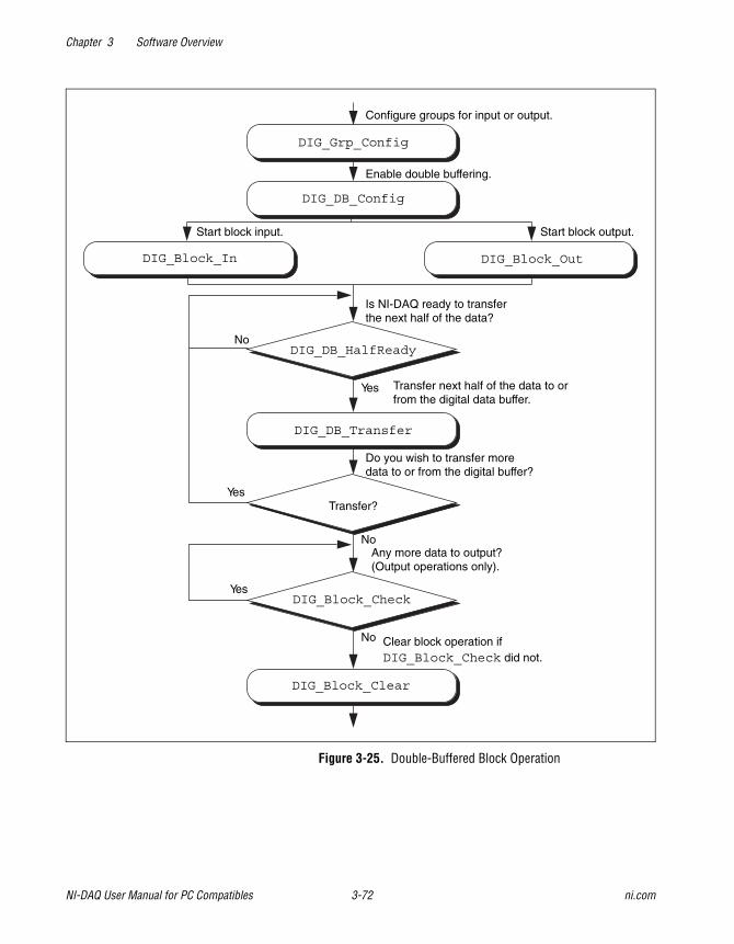
Chapter 3 Software Overview
NI-DAQ User Manual for PC Compatibles 3-72 ni.com
Figure 3-25. Double-Buffered Block Operation
DIG_Grp_Config
DIG_Block_In DIG_Block_Out
Any more data to output?(Output operations only).
No
Yes
Clear block operation ifDIG_Block_Check did not.
DIG_Block_Clear
DIG_Block_Check
No
Configure groups for input or output.
Enable double buffering.
Start block input. Start block output.
DIG_DB_HalfReady
DIG_DB_Transfer
Transfer?Yes
No
Yes
Is NI-DAQ ready to transferthe next half of the data?
Transfer next half of the data to orfrom the digital data buffer.
Do you wish to transfer moredata to or from the digital buffer?
DIG_DB_Config
Chapter 3 Software Overview
© National Instruments Corporation 3-73 NI-DAQ User Manual for PC Compatibles
The first step for an application is to call DIG_Grp_Config to configureindividual ports as a group. Although the steps have been left out of thediagram, you can alter the handshaking mode and enable pattern generationas shown in Figure 3-24, and explained in the Digital Group Block I/OApplications section earlier in this chapter. Next, enable double bufferingby calling DIG_DB_Config (second step of Figure 3-25). To start thedigital block input or output, call DIG_Block_In or DIG_Block_Out.
After the operation has started, you can perform unlimited transfers to orfrom the circular buffer. Input operations transfer new data from the digitalbuffer for storage or processing. Output operations transfer new data to thedigital buffer for output.
To transfer to or from the circular buffer, call the DIG_DB_Transferfunction. After you call the function, NI-DAQ waits until it can transferthe data before returning to the application. To avoid the waiting period,call DIG_DB_HalfReady to determine if NI-DAQ can make the transferimmediately. If DIG_DB_HalfReady indicates that NI-DAQ is not readyfor a transfer, your application can do other processing and check the statuslater.
After the final transfer, you can call DIG_Block_Check to get the currentprogress of the transfer. For example, if you are using double-bufferedoutput, NI-DAQ requires some time after the final transfer to actuallyoutput the data. In addition, if NI-DAQ completes the block operation priorto a DIG_Block_Check call, DIG_Block_Check automatically callsDIG_Block_Clear to perform cleanup work.
The final step of a double-buffered block operation is to callDIG_Block_Clear, which performs the necessary cleanup work aftera digital block operation. You must explicitly call this function ifDIG_Block_Check did not already call it.
Note DIG_Block_Clear halts any ongoing block operation. Therefore,call DIG_Block_Clear only if you are certain the block operation is complete or ifyou want to stop the current operation.
Chapter 3 Software Overview
NI-DAQ User Manual for PC Compatibles 3-74 ni.com
Pattern Generation I/O with the DIO-32F, 653X, PCI-6115,and PCI-6120 Devices
Use pattern generation for clocked digital I/O when you have a groupthat is written to or read from based on the output of a counter. TheDIG_Block_PG_Config function enables the pattern generationmode of digital I/O. When pattern generation is enabled, a subsequentDIG_Block_In or DIG_Block_Out call automatically uses this mode.Each group for the DIO-32F and 653X devices has its own onboard counterso that each can simultaneously run in this mode at different rates. Use anexternal counter by connecting its output to the appropriate REQ pin at theI/O connector. For an input group, pattern generation is analogous to adata acquisition operation, but instead of reading analog input channels,NI-DAQ reads the digital ports. For an output group, pattern generation isanalogous to waveform generation, but instead of writing voltages to theanalog output channels, NI-DAQ writes digital patterns to the digital ports.
The DIO-32F, 653X, PCI-6115, and PCI-6120 use DMA to service patterngeneration. However, certain buffers require NI-DAQ to reprogramthe DMA controller during the pattern generation. The extra time neededto reprogram increases the minimum request interval (thus decreasing themaximum rate unless you use dual DMA). Refer to Chapter 4, NI-DAQDouble Buffering, for more information.
Note For the AT-DIO-32F, DIG_Block_In and DIG_Block_Out return a warning if it isnecessary to reprogram the DMA controller. Also, page boundaries in a buffer that is to beused for 32-bit digital pattern generation cause unpredictable results for AT bus computerusers, regardless of the request interval used.
For the DIO-32F, another option is to use the utility functionAlign_DMA_Buffer to avoid the negative effects of page boundaries inthe following cases:
• When using digital I/O pattern generation at small request intervalsfor buffers with page boundaries
• When using 32-bit digital I/O pattern generation at any speed
To use Align_DMA_Buffer, however, you must allocate a buffer that islarger than the sample count to make room for Align_DMA_Buffer tomove the data around. When the buffer is aligned, make the normal callsto DIG_Block_In and DIG_Block_Out. A call to DIG_Block_Clear
(either directly or indirectly through DIG_Block_Check) unaligns thedata buffer if the data buffer was previously aligned by a call to
Chapter 3 Software Overview
© National Instruments Corporation 3-75 NI-DAQ User Manual for PC Compatibles
Align_DMA_Buffer. To use the Align_DMA_Buffer utility function,follow these steps:
1. Allocate a buffer twice as large as the number of data samples you aregenerating.
2. If you are using digital output, build your digital pattern in the buffer.
3. Call DIG_Grp_Config for port assignment.
4. Call DIG_Block_PG_Config to enable pattern generation.
5. Call Align_DMA_Buffer, as described in the NI-DAQ FunctionReference Online Help file.
6. Call DIG_Block_In or DIG_Block_Out with the aligned buffer toinitiate the process.
7. Call DIG_Block_Clear after the pattern generation completes.
8. Because DIG_Block_Clear unaligns the buffer, you can access thedigital input pattern generation as you can with an unaligned buffer.To use the same buffer again for digital output pattern generation,you must call Align_DMA_Buffer again.
Double-Buffered I/OWith the double-buffered (DIG_DB) digital I/O functions, you can inputor output unlimited digital data without requiring unlimited memory.Double-buffered digital I/O is useful for applications such as streamingdata to disk and sending long data streams as output to external devices.For an explanation of double-buffering, refer to Chapter 4, NI-DAQDouble Buffering.
Digital double-buffered output operations have two options. The firstoption is to stop the digital block operation if old data is ever encountered.This occurs if the DIG_DB_Transfer function calls are not keeping pacewith the data input or output rate; that is, new data is not transferred toor from the circular buffer quickly enough. For digital input, this optionprevents the loss of incoming data. For digital output, this option preventserroneous data from being transferred to an external device. If the group isconfigured for handshaking, an old data stop is only a pause and a call toone of the transfer functions resumes the digital operation. If the group isconfigured for pattern generation, an old data stop forces you to clear andrestart the block operation.
The second option, available only to output groups, is the ability to transferdata that is less than half the circular buffer size to the circular buffer. Thisoption is useful when long digital data streams are being output, but the sizeof the data stream is not evenly divisible by the size of half of the circular
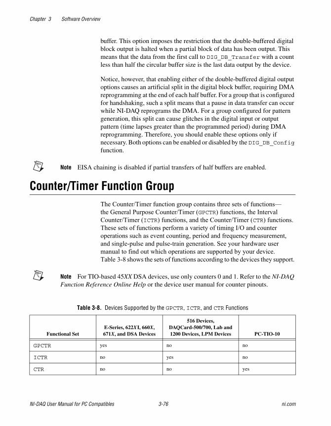
Chapter 3 Software Overview
NI-DAQ User Manual for PC Compatibles 3-76 ni.com
buffer. This option imposes the restriction that the double-buffered digitalblock output is halted when a partial block of data has been output. Thismeans that the data from the first call to DIG_DB_Transfer with a countless than half the circular buffer size is the last data output by the device.
Notice, however, that enabling either of the double-buffered digital outputoptions causes an artificial split in the digital block buffer, requiring DMAreprogramming at the end of each half buffer. For a group that is configuredfor handshaking, such a split means that a pause in data transfer can occurwhile NI-DAQ reprograms the DMA. For a group configured for patterngeneration, this split can cause glitches in the digital input or outputpattern (time lapses greater than the programmed period) during DMAreprogramming. Therefore, you should enable these options only ifnecessary. Both options can be enabled or disabled by the DIG_DB_Configfunction.
Note EISA chaining is disabled if partial transfers of half buffers are enabled.
Counter/Timer Function GroupThe Counter/Timer function group contains three sets of functions—the General Purpose Counter/Timer (GPCTR) functions, the Interval Counter/Timer (ICTR) functions, and the Counter/Timer (CTR) functions. These sets of functions perform a variety of timing I/O and counter operations such as event counting, period and frequency measurement, and single-pulse and pulse-train generation. See your hardware user manual to find out which operations are supported by your device. Table 3-8 shows the sets of functions according to the devices they support.
Note For TIO-based 45XX DSA devices, use only counters 0 and 1. Refer to the NI-DAQFunction Reference Online Help or the device user manual for counter pinouts.
Table 3-8. Devices Supported by the GPCTR, ICTR, and CTR Functions
Functional SetE-Series, 622XI, 660X,671X, and DSA Devices
516 Devices,DAQCard-500/700, Lab and1200 Devices, LPM Devices PC-TIO-10
GPCTR yes no no
ICTR no yes no
CTR no no yes
Chapter 3 Software Overview
© National Instruments Corporation 3-77 NI-DAQ User Manual for PC Compatibles
Counter/Timer FunctionsThe Counter/Timer (CTR) functions perform counting timing I/O andtiming counter operations on the Am9513-based MIO devices and thePC-TIO-10:
CTR_Config Specifies the counting configuration to usefor a counter.
CTR_EvCount Configures the specified counter for anevent-counting operation and starts thecounter.
CTR_EvRead Reads the current counter total withoutdisturbing the counting process and returnsthe count and overflow conditions.
CTR_FOUT_Config Disables or enables and sets the frequencyof the 4-bit programmable frequencyoutput.
CTR_Period Configures the specified counter for periodor pulse-width measurement.
CTR_Pulse Causes the specified counter to generate aspecified pulse-programmable delay andpulse width.
CTR_Rate Converts frequency and duty-cyclevalues of a square wave you want into thetimebase and period parameters needed forinput to the CTR_Square function thatproduces the square wave.
CTR_Reset Turns off the specified counter operationand places the counter output drivers in theselected output state.
CTR_Restart Restarts the specified counter operation.
CTR_Simul_Op Configures and simultaneously starts andstops multiple counters.
CTR_Square Causes the specified counter to generate acontinuous square wave output of specifiedduty cycle and frequency.
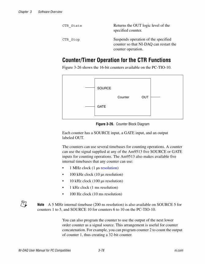
Chapter 3 Software Overview
NI-DAQ User Manual for PC Compatibles 3-78 ni.com
CTR_State Returns the OUT logic level of thespecified counter.
CTR_Stop Suspends operation of the specifiedcounter so that NI-DAQ can restart thecounter operation.
Counter/Timer Operation for the CTR FunctionsFigure 3-26 shows the 16-bit counters available on the PC-TIO-10.
Figure 3-26. Counter Block Diagram
Each counter has a SOURCE input, a GATE input, and an outputlabeled OUT.
The counters can use several timebases for counting operations. A countercan use the signal supplied at any of the Am9513 five SOURCE or GATEinputs for counting operations. The Am9513 also makes available fiveinternal timebases that any counter can use:
• 1 MHz clock (1 µs resolution)
• 100 kHz clock (10 µs resolution)
• 10 kHz clock (100 µs resolution)
• 1 kHz clock (1 ms resolution)
• 100 Hz clock (10 ms resolution)
Note A 5 MHz internal timebase (200 ns resolution) is also available on SOURCE 5 forcounters 1 to 5, and SOURCE 10 for counters 6 to 10 on the PC-TIO-10.
You can also program the counter to use the output of the next lowerorder counter as a signal source. This arrangement is useful for counterconcatenation. For example, you can program counter 2 to count the outputof counter 1, thus creating a 32-bit counter.
GATE
SOURCE
Counter OUT
Chapter 3 Software Overview
© National Instruments Corporation 3-79 NI-DAQ User Manual for PC Compatibles
You can configure a counter to count either falling or rising edges of theselected internal timebase, SOURCE input, GATE input, or next lowerorder counter signal.
You can use the counter GATE input to gate counting operations. After yousoftware-configure a counter for an operation, a signal at the GATE inputcan start and stop the counter operation. There are nine gating modesavailable in the Am9513:
• No Gating—Counter is started and stopped by software.
• High-Level Gating—Counter is active when its gate input is athigh-logic state. The counter is suspended when its gate input isat low-logic state.
• Low-Level Gating—Counter is active when its gate input is atlow-logic state. The counter is suspended when its gate input isat high-logic state.
• Rising Edge Gating—Counter starts counting when it receives alow-to-high edge at its gate input.
• Falling Edge Gating—Counter starts counting when it receives ahigh-to-low edge at its gate input.
• High Terminal Count Gating—Counter is active when the next lowerorder counter reaches terminal count (TC) and generates a TC pulse.
• High-Level Gate N+1 Gating—Counter is active when the gate inputof the next higher-order counter is at high-logic state. Otherwise, thecounter is suspended.
• High-Level Gate N–1 Gating—Counter is active when the gate inputof the next lower order counter is at high-logic state. Otherwise, thecounter is suspended.
• Special Gating—The gate input selects the reload source but does notstart counting. The counter uses the value stored in its internal Holdregister when the gate input is high, and uses the value stored in itsinternal Load register when the gate input is low.
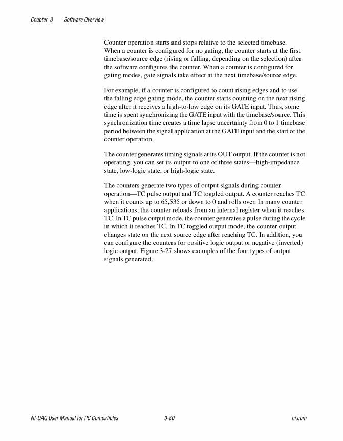
Chapter 3 Software Overview
NI-DAQ User Manual for PC Compatibles 3-80 ni.com
Counter operation starts and stops relative to the selected timebase.When a counter is configured for no gating, the counter starts at the firsttimebase/source edge (rising or falling, depending on the selection) afterthe software configures the counter. When a counter is configured forgating modes, gate signals take effect at the next timebase/source edge.
For example, if a counter is configured to count rising edges and to usethe falling edge gating mode, the counter starts counting on the next risingedge after it receives a high-to-low edge on its GATE input. Thus, sometime is spent synchronizing the GATE input with the timebase/source. Thissynchronization time creates a time lapse uncertainty from 0 to 1 timebaseperiod between the signal application at the GATE input and the start of thecounter operation.
The counter generates timing signals at its OUT output. If the counter is notoperating, you can set its output to one of three states—high-impedancestate, low-logic state, or high-logic state.
The counters generate two types of output signals during counteroperation—TC pulse output and TC toggled output. A counter reaches TCwhen it counts up to 65,535 or down to 0 and rolls over. In many counterapplications, the counter reloads from an internal register when it reachesTC. In TC pulse output mode, the counter generates a pulse during the cyclein which it reaches TC. In TC toggled output mode, the counter outputchanges state on the next source edge after reaching TC. In addition, youcan configure the counters for positive logic output or negative (inverted)logic output. Figure 3-27 shows examples of the four types of outputsignals generated.
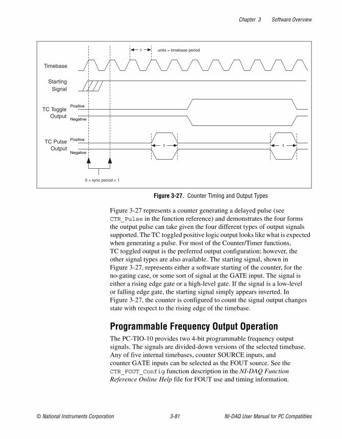
Chapter 3 Software Overview
© National Instruments Corporation 3-81 NI-DAQ User Manual for PC Compatibles
Figure 3-27. Counter Timing and Output Types
Figure 3-27 represents a counter generating a delayed pulse (seeCTR_Pulse in the function reference) and demonstrates the four formsthe output pulse can take given the four different types of output signalssupported. The TC toggled positive logic output looks like what is expectedwhen generating a pulse. For most of the Counter/Timer functions,TC toggled output is the preferred output configuration; however, theother signal types are also available. The starting signal, shown inFigure 3-27, represents either a software starting of the counter, for theno-gating case, or some sort of signal at the GATE input. The signal iseither a rising edge gate or a high-level gate. If the signal is a low-levelor falling edge gate, the starting signal simply appears inverted. InFigure 3-27, the counter is configured to count the signal output changesstate with respect to the rising edge of the timebase.
Programmable Frequency Output OperationThe PC-TIO-10 provides two 4-bit programmable frequency outputsignals. The signals are divided-down versions of the selected timebase.Any of five internal timebases, counter SOURCE inputs, andcounter GATE inputs can be selected as the FOUT source. See theCTR_FOUT_Config function description in the NI-DAQ FunctionReference Online Help file for FOUT use and timing information.
0 < sync period < 1
1
Timebase
StartingSignal
TC ToggleOutput
TC PulseOutput
units = timebase period
Positive
Negative
Positive
Negative
1 1
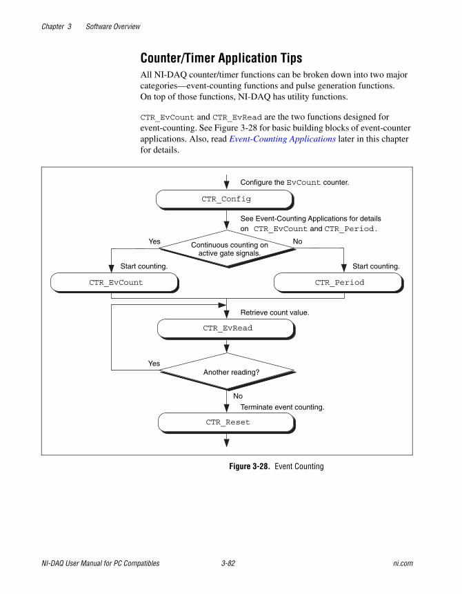
Chapter 3 Software Overview
NI-DAQ User Manual for PC Compatibles 3-82 ni.com
Counter/Timer Application TipsAll NI-DAQ counter/timer functions can be broken down into two majorcategories—event-counting functions and pulse generation functions.On top of those functions, NI-DAQ has utility functions.
CTR_EvCount and CTR_EvRead are the two functions designed forevent-counting. See Figure 3-28 for basic building blocks of event-counterapplications. Also, read Event-Counting Applications later in this chapterfor details.
Figure 3-28. Event Counting
CTR_Config
CTR_EvCount CTR_Period
CTR_EvRead
CTR_Reset
Another reading?
Continuous counting onactive gate signals.
Configure the EvCount counter.
See Event-Counting Applications for detailson CTR_EvCount and CTR_Period.
NoYes
Start counting. Start counting.
Retrieve count value.
No
Yes
Terminate event counting.
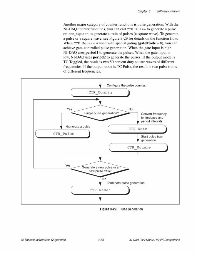
Chapter 3 Software Overview
© National Instruments Corporation 3-83 NI-DAQ User Manual for PC Compatibles
Another major category of counter functions is pulse generation. With theNI-DAQ counter functions, you can call CTR_Pulse to generate a pulseor CTR_Square to generate a train of pulses (a square wave). To generatea pulse or a square wave, see Figure 3-29 for details on the function flow.When CTR_Square is used with special gating (gateMode = 8), you canachieve gate-controlled pulse generation. When the gate input is high,NI-DAQ uses period1 to generate the pulses. When the gate input islow, NI-DAQ uses period2 to generate the pulses. If the output mode isTC Toggled, the result is two 50 percent duty square waves of differentfrequencies. If the output mode is TC Pulse, the result is two pulse trainsof different frequencies.
Figure 3-29. Pulse Generation
CTR_Config
CTR_PulseCTR_Rate
CTR_Reset
Generate a new pulse or anew pulse train?
Single pulse generation?NoYes
Generate a pulse
Convert frequencyto timebase andperiod intervals.
No
Yes
Terminate pulse generation.
CTR_Square
Start pulse traingeneration.
Configure the pulse counter.
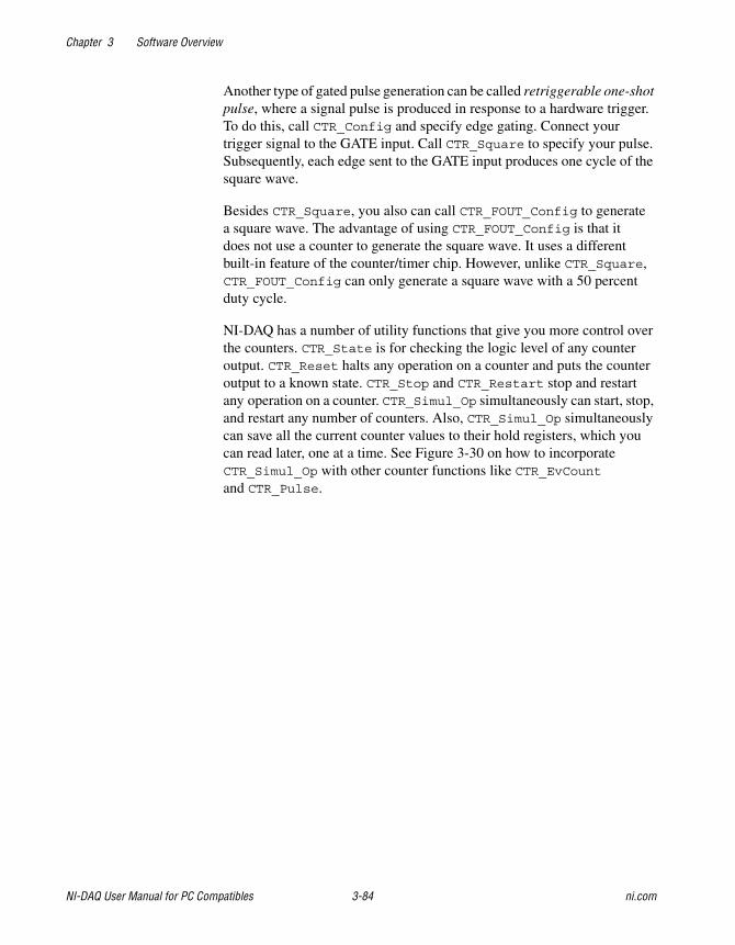
Chapter 3 Software Overview
NI-DAQ User Manual for PC Compatibles 3-84 ni.com
Another type of gated pulse generation can be called retriggerable one-shotpulse, where a signal pulse is produced in response to a hardware trigger.To do this, call CTR_Config and specify edge gating. Connect yourtrigger signal to the GATE input. Call CTR_Square to specify your pulse.Subsequently, each edge sent to the GATE input produces one cycle of thesquare wave.
Besides CTR_Square, you also can call CTR_FOUT_Config to generatea square wave. The advantage of using CTR_FOUT_Config is that itdoes not use a counter to generate the square wave. It uses a differentbuilt-in feature of the counter/timer chip. However, unlike CTR_Square,CTR_FOUT_Config can only generate a square wave with a 50 percentduty cycle.
NI-DAQ has a number of utility functions that give you more control overthe counters. CTR_State is for checking the logic level of any counteroutput. CTR_Reset halts any operation on a counter and puts the counteroutput to a known state. CTR_Stop and CTR_Restart stop and restartany operation on a counter. CTR_Simul_Op simultaneously can start, stop,and restart any number of counters. Also, CTR_Simul_Op simultaneouslycan save all the current counter values to their hold registers, which youcan read later, one at a time. See Figure 3-30 on how to incorporateCTR_Simul_Op with other counter functions like CTR_EvCountand CTR_Pulse.
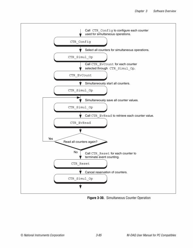
Chapter 3 Software Overview
© National Instruments Corporation 3-85 NI-DAQ User Manual for PC Compatibles
Figure 3-30. Simultaneous Counter Operation
CTR_Config
CTR_Simul_Op
CTR_EvCount
CTR_Simul_Op
CTR_Simul_Op
CTR_EvRead
Read all counters again?Yes
No
CTR_Reset
Call CTR_Config to configure each counterused for simultaneous operations.
Select all counters for simultaneous operations.
Call CTR_EvCount for each counterselected through CTR_Simul_Op.
Simultaneously start all counters.
Simultaneously save all counter values.
Call CTR_EvRead to retrieve each counter value.
Call CTR_Reset for each counter toterminate event counting.
CTR_Simul_Op
Cancel reservation of counters.
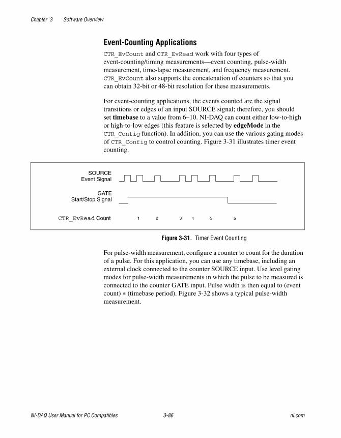
Chapter 3 Software Overview
NI-DAQ User Manual for PC Compatibles 3-86 ni.com
Event-Counting ApplicationsCTR_EvCount and CTR_EvRead work with four types ofevent-counting/timing measurements—event counting, pulse-widthmeasurement, time-lapse measurement, and frequency measurement.CTR_EvCount also supports the concatenation of counters so that youcan obtain 32-bit or 48-bit resolution for these measurements.
For event-counting applications, the events counted are the signaltransitions or edges of an input SOURCE signal; therefore, you shouldset timebase to a value from 6–10. NI-DAQ can count either low-to-highor high-to-low edges (this feature is selected by edgeMode in theCTR_Config function). In addition, you can use the various gating modesof CTR_Config to control counting. Figure 3-31 illustrates timer eventcounting.
Figure 3-31. Timer Event Counting
For pulse-width measurement, configure a counter to count for the durationof a pulse. For this application, you can use any timebase, including anexternal clock connected to the counter SOURCE input. Use level gatingmodes for pulse-width measurements in which the pulse to be measured isconnected to the counter GATE input. Pulse width is then equal to (eventcount) * (timebase period). Figure 3-32 shows a typical pulse-widthmeasurement.
1 2 3 4 5 5
SOURCEEvent Signal
GATEStart/Stop Signal
CTR_EvRead Count
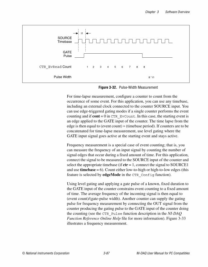
Chapter 3 Software Overview
© National Instruments Corporation 3-87 NI-DAQ User Manual for PC Compatibles
Figure 3-32. Pulse-Width Measurement
For time-lapse measurement, configure a counter to count from theoccurrence of some event. For this application, you can use any timebase,including an external clock connected to the counter SOURCE input. Youcan use edge-triggered gating modes if a single counter performs the eventcounting and if cont = 0 in CTR_EvCount. In this case, the starting event isan edge applied to the GATE input of the counter. The time lapse from theedge is then equal to (event count) * (timebase period). If counters are to beconcatenated for time-lapse measurement, use level gating where theGATE input signal goes active at the starting event and stays active.
Frequency measurement is a special case of event counting; that is, youcan measure the frequency of an input signal by counting the number ofsignal edges that occur during a fixed amount of time. For this application,connect the signal to be measured to the SOURCE input of the counter andselect the appropriate timebase (if ctr = 1, connect the signal to SOURCE1and use timebase = 6). Count either low-to-high or high-to-low edges (thisfeature is selected by edgeMode in the CTR_Config function).
Using level gating and applying a gate pulse of a known, fixed duration tothe GATE input of the counter constrains event counting to a fixed amountof time. The average frequency of the incoming signal is then equal to(event count)/(gate-pulse width). Another counter can supply the gatingpulse for frequency measurement by connecting the OUT signal from thecounter producing the gating pulse to the GATE input of the counter doingthe counting (see the CTR_Pulse function description in the NI-DAQFunction Reference Online Help file for more information). Figure 3-33illustrates a frequency measurement.
SOURCETimebase
GATEPulse
CTR_EvRead Count
Pulse Width
1 2 3 4 5 6 7 8 8
8 * t1
t1
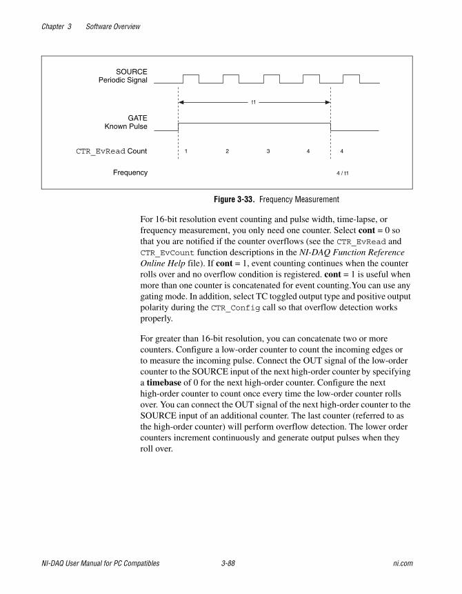
Chapter 3 Software Overview
NI-DAQ User Manual for PC Compatibles 3-88 ni.com
Figure 3-33. Frequency Measurement
For 16-bit resolution event counting and pulse width, time-lapse, orfrequency measurement, you only need one counter. Select cont = 0 sothat you are notified if the counter overflows (see the CTR_EvRead andCTR_EvCount function descriptions in the NI-DAQ Function ReferenceOnline Help file). If cont = 1, event counting continues when the counterrolls over and no overflow condition is registered. cont = 1 is useful whenmore than one counter is concatenated for event counting.You can use anygating mode. In addition, select TC toggled output type and positive outputpolarity during the CTR_Config call so that overflow detection worksproperly.
For greater than 16-bit resolution, you can concatenate two or morecounters. Configure a low-order counter to count the incoming edges orto measure the incoming pulse. Connect the OUT signal of the low-ordercounter to the SOURCE input of the next high-order counter by specifyinga timebase of 0 for the next high-order counter. Configure the nexthigh-order counter to count once every time the low-order counter rollsover. You can connect the OUT signal of the next high-order counter to theSOURCE input of an additional counter. The last counter (referred to asthe high-order counter) will perform overflow detection. The lower ordercounters increment continuously and generate output pulses when theyroll over.
SOURCEPeriodic Signal
GATEKnown Pulse
CTR_EvRead Count
Frequency
1 2 3 4 4
4 / t1
t1
Chapter 3 Software Overview
© National Instruments Corporation 3-89 NI-DAQ User Manual for PC Compatibles
For 32-bit counting, use two counters. For 48-bit counting, use threecounters, and so on. The counter configurations for concatenated eventcounting are as follows:
• Low-order counter configuration
gateMode—either level gating or no gating
edgeMode—any value
outType—TC pulse output type
outPolarity—positive polarity
timebase—any value
cont = 1—continuous counting
• Intermediate counter configuration
edgeMode—count rising edges (indicates that the low-order counterrolled over)
gateMode—no gating
outType—TC pulse output type
outPolarity—positive polarity
timebase = 0—counts lower order counter output
cont = 1—continuous counting
• High-order counter configuration
edgeMode—count rising edges (indicates that the low-order counterrolled over)
gateMode—no gating
outType—TC-toggled output type (for proper overflow detection)
outPolarity—positive polarity
timebase = 0—counts lower order counter output
cont = 0—counter stops on overflow
Period and Continuous Pulse-Width MeasurementApplicationsWith the proper use of CTR_Config, CTR_Period, and CTR_EvRead,you can configure a counter to make period or continuous pulse-widthmeasurements.
To make a period measurement, call CTR_Config with gateMode setto either rising or falling edge-triggered gating (3 or 4). With risingedge-triggered gating, a counter can measure the time interval
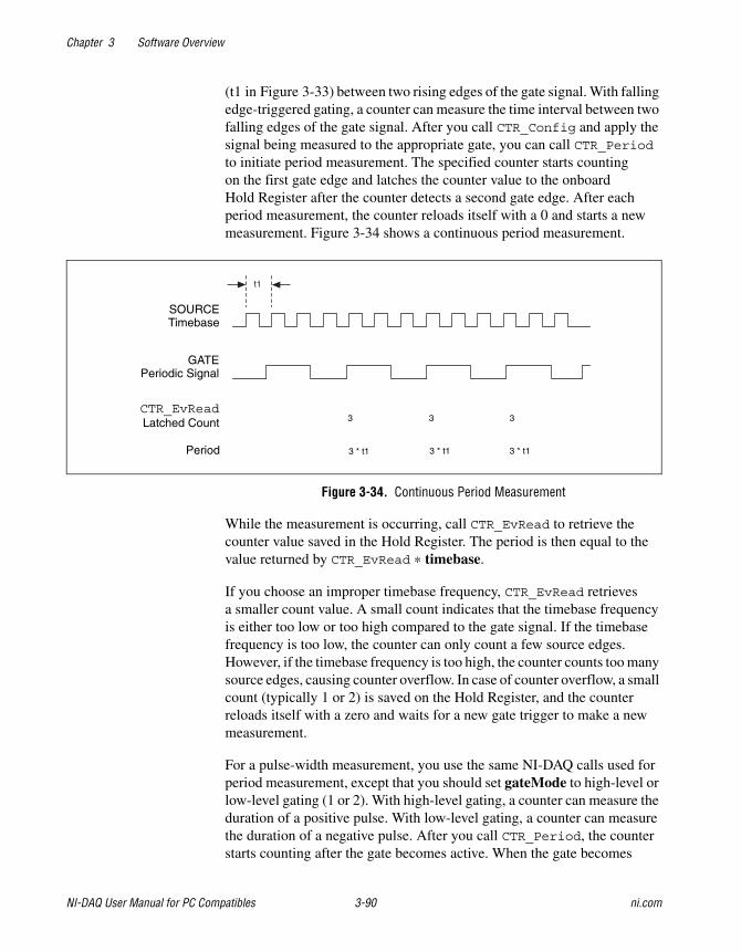
Chapter 3 Software Overview
NI-DAQ User Manual for PC Compatibles 3-90 ni.com
(t1 in Figure 3-33) between two rising edges of the gate signal. With fallingedge-triggered gating, a counter can measure the time interval between twofalling edges of the gate signal. After you call CTR_Config and apply thesignal being measured to the appropriate gate, you can call CTR_Periodto initiate period measurement. The specified counter starts countingon the first gate edge and latches the counter value to the onboardHold Register after the counter detects a second gate edge. After eachperiod measurement, the counter reloads itself with a 0 and starts a newmeasurement. Figure 3-34 shows a continuous period measurement.
Figure 3-34. Continuous Period Measurement
While the measurement is occurring, call CTR_EvRead to retrieve thecounter value saved in the Hold Register. The period is then equal to thevalue returned by CTR_EvRead * timebase.
If you choose an improper timebase frequency, CTR_EvRead retrievesa smaller count value. A small count indicates that the timebase frequencyis either too low or too high compared to the gate signal. If the timebasefrequency is too low, the counter can only count a few source edges.However, if the timebase frequency is too high, the counter counts too manysource edges, causing counter overflow. In case of counter overflow, a smallcount (typically 1 or 2) is saved on the Hold Register, and the counterreloads itself with a zero and waits for a new gate trigger to make a newmeasurement.
For a pulse-width measurement, you use the same NI-DAQ calls used forperiod measurement, except that you should set gateMode to high-level orlow-level gating (1 or 2). With high-level gating, a counter can measure theduration of a positive pulse. With low-level gating, a counter can measurethe duration of a negative pulse. After you call CTR_Period, the counterstarts counting after the gate becomes active. When the gate becomes
SOURCETimebase
GATEPeriodic Signal
CTR_EvReadLatched Count
Period
3
3 * t1
t1
3 3
3 * t13 * t1
Chapter 3 Software Overview
© National Instruments Corporation 3-91 NI-DAQ User Manual for PC Compatibles
inactive, the counter value latches to the Hold Register. You then can callCTR_EvRead to retrieve the saved value. Pulse width is then equal to thevalue returned by CTR_EvRead * timebase. When the counter value islatched to the Hold Register, the counter reloads itself with a zero andwaits for the gate to go active to begin a new measurement.
For measuring pulse width, you need a rough estimate of the duration ofthe pulse being measured. When you configure a counter to measure pulsewidth, the counter continues counting in case of overflow. No counter valueis latched to the Hold Register until the gate signal becomes inactive.To detect the counter overflow, feed the output of the pulse-widthmeasurement counter to the source input of an event-counting counter.If the event-counting counter value is not zero after the pulse-widthmeasurement, the pulse-width measurement is not correct.
Interval Counter/Timer FunctionsThe Interval Counter/Timer functions perform interval timing I/O andcounter operations on the 516 devices, DAQCard-500/700, Lab and1200 devices, and LPM devices.
Refer to the NI-DAQ Function Reference Online Help file to determinewhich functions your device supports.
ICTR_Read Returns the current contents of the selected counterwithout disturbing the counting process and returnsthe count.
ICTR_Reset Sets the output of the selected counter to thespecified state.
ICTR_Setup Configures the assigned counter to operate in thespecified mode.
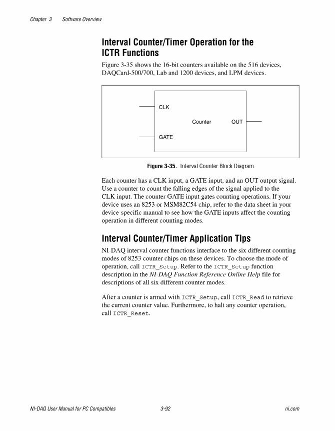
Chapter 3 Software Overview
NI-DAQ User Manual for PC Compatibles 3-92 ni.com
Interval Counter/Timer Operation for theICTR FunctionsFigure 3-35 shows the 16-bit counters available on the 516 devices,DAQCard-500/700, Lab and 1200 devices, and LPM devices.
Figure 3-35. Interval Counter Block Diagram
Each counter has a CLK input, a GATE input, and an OUT output signal.Use a counter to count the falling edges of the signal applied to theCLK input. The counter GATE input gates counting operations. If yourdevice uses an 8253 or MSM82C54 chip, refer to the data sheet in yourdevice-specific manual to see how the GATE inputs affect the countingoperation in different counting modes.
Interval Counter/Timer Application TipsNI-DAQ interval counter functions interface to the six different countingmodes of 8253 counter chips on these devices. To choose the mode ofoperation, call ICTR_Setup. Refer to the ICTR_Setup functiondescription in the NI-DAQ Function Reference Online Help file fordescriptions of all six different counter modes.
After a counter is armed with ICTR_Setup, call ICTR_Read to retrievethe current counter value. Furthermore, to halt any counter operation,call ICTR_Reset.
GATE
CLK
Counter OUT
Chapter 3 Software Overview
© National Instruments Corporation 3-93 NI-DAQ User Manual for PC Compatibles
General-Purpose Counter/Timer FunctionsUse the General-Purpose Counter/Timer (GPCTR) functions with theE Series, 622XI, 660X, 671X, NI-TIO based, and DSA devices. Refer to theGPCTR functions in the NI-DAQ Function Reference Online Help file for adetailed description of how to use the GPCTR functions for a variety ofapplications.
GPCTR_Change_Parameter Customizes the counter operation to fitthe requirements of your application byselecting a specific parameter setting.
GPCTR_Config_Buffer Assigns the buffer that NI-DAQ uses fora buffered counter operation.
GPCTR_Control Controls the operation of thegeneral-purpose counter.
GPCTR_Read_Buffer Transfers data from the previouslyassigned buffer during an asynchronouscounter operation.
GPCTR_Set_Application Selects the application for which you usethe general-purpose counter. The functiondescription in the NI-DAQ FunctionReference Online Help file containsmany application tips.
GPCTR_Watch Monitors the state of the general-purposecounter and its operation.
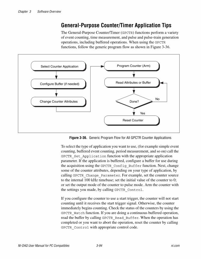
Chapter 3 Software Overview
NI-DAQ User Manual for PC Compatibles 3-94 ni.com
General-Purpose Counter/Timer Application TipsThe General-Purpose Counter/Timer (GPCTR) functions perform a varietyof event counting, time measurement, and pulse and pulse-train generationoperations, including buffered operations. When using the GPCTR functions, follow the generic program flow as shown in Figure 3-36.
Figure 3-36. Generic Program Flow for All GPCTR Counter Applications
To select the type of application you want to use, (for example simple eventcounting, buffered event counting, period measurement, and so on) call theGPCTR_Set_Application function with the appropriate applicationparameter. If the application is buffered, configure a buffer for use duringthe acquisition using the GPCTR_Config_Buffer function. Next, changesome of the counter attributes, depending on your type of application, bycalling GPCTR_Change_Parameter. For example, set the counter sourceto the internal 100 kHz timebase; set the initial value of the counter to 0;or set the output mode of the counter to pulse mode. Arm the counter withthe settings you made, by calling GPCTR_Control.
If you configure the counter to use a start trigger, the counter will not startcounting until it receives the start trigger signal. Otherwise, the counterimmediately begins counting. Check the status of the counters by using theGPCTR_Watch function. If you are doing a continuous buffered operation,read the buffer by calling GPCTR_Read_Buffer. When the operation hascompleted or you want to abort the operation, reset the counter by callingGPCTR_Control with appropriate control code.
Done?No
Read Attributes or BufferConfigure Buffer (if needed)
Select Counter Application Program Counter (Arm)
Change Counter Attributes
Reset Counter
Yes
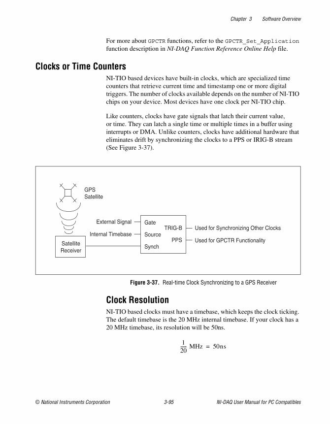
Chapter 3 Software Overview
© National Instruments Corporation 3-95 NI-DAQ User Manual for PC Compatibles
For more about GPCTR functions, refer to the GPCTR_Set_Applicationfunction description in NI-DAQ Function Reference Online Help file.
Clocks or Time CountersNI-TIO based devices have built-in clocks, which are specialized timecounters that retrieve current time and timestamp one or more digitaltriggers. The number of clocks available depends on the number of NI-TIOchips on your device. Most devices have one clock per NI-TIO chip.
Like counters, clocks have gate signals that latch their current value,or time. They can latch a single time or multiple times in a buffer usinginterrupts or DMA. Unlike counters, clocks have additional hardware thateliminates drift by synchronizing the clocks to a PPS or IRIG-B stream(See Figure 3-37).
Figure 3-37. Real-time Clock Synchronizing to a GPS Receiver
Clock ResolutionNI-TIO based clocks must have a timebase, which keeps the clock ticking.The default timebase is the 20 MHz internal timebase. If your clock has a20 MHz timebase, its resolution will be 50ns.
GateExternal SignalUsed for Synchronizing Other Clocks
Used for GPCTR Functionality
GPSSatellite
Internal Timebase Source
SynchSatelliteReceiver
TRIG-B
PPS
120------ MHz 50ns=
Chapter 3 Software Overview
NI-DAQ User Manual for PC Compatibles 3-96 ni.com
Clock SynchronizationClocks can be synchronized using an external source. Currently, there aretwo supported types of synchronization—Pulse Per Second (PPS), andIRIG B.
Pulse Per SecondPPS, the simplest type of synchronization, is a very accurate 1 Hz signal.Depending on your satellite receiver, the accuracy of this signal can varyfrom 300 to 100 ns. The disadvantage of PPS is that no absolute timinginformation is encoded in the pulse, so you must set the initial time of theclock. After that, the PPS keeps the subsecond counters synchronized.The initial time for NI-TIO clocks is specified in seconds from 12:00 a.m.,January 1 of the current year. You can think of this as Julian seconds if itis easier. Most GPS receivers produce a PPS stream.
You must allow for a window of error when using PPS. When you receivethe time from the receiver, you must set the clock up within 1 second. Ifyou wait any longer, your clock will be off by 1 or more seconds. TheSetUpClockUsingPPS section shows pseudocode for ensuring that yourclock has been set safely.
SetUpClockUsingPPSComment: Get the latest time from the RS-232 port of the
receiver. It has a Comment: resolution of one second.
initialTime = Satellite Receiver Time
lastTime = initialTime
Comment: This is for initialization.
While (initialTime = lastTime)
Comment: Get the latest time.
lastTime = Satellite Receiver Time
Comment: We now are at the beginning of the next second.
Comment: This will minimize the chance of taking too long
Comment: to program the clock.
GPCTR_Control(deviceNumber, ND_CLOCK_x, ND_RESET)
GPCTR_Set_Application(deviceNumber, ND_CLOCK_x,
ND_SIMPLE_TIME_MSR)
Chapter 3 Software Overview
© National Instruments Corporation 3-97 NI-DAQ User Manual for PC Compatibles
GPCTR_Change_Parameter(deviceNumber, ND_CLOCK_x,
ND_SYNCHRONIZATION_METHOD, ND_PULSE_PER_SECOND)
GPCTR_Change_Parameter(deviceNumber, ND_CLOCK_x,
ND_SECONDS,lastTime)
GPCTR_Control(deviceNumber, ND_CLOCK_x, ND_PROGRAM)
Comment: We have programmed the clock. Now we need to
Comment: make sure that the Comment: programming was
Comment: really successful.
timeAfterProgramming = Satellite Receiver Time
if (timeAfterProgramming = lastTime)
Comment: We were successful in programming the clock in
Comment: time!
else
Comment: We didn't make it in time. Try again…
IRIGThe Inter Range Instrumentation Group (IRIG) defines a series oftime-code protocols, which transmit a series of data frames that providetiming information in the binary data of the frame as well as at the start offrame time. The clock synchronization uses a subset of the IRIG-B protocolfor synchronization. The IRIG-B frame consists of 100 bits, each of whichis pulse-width modulated for 10 ms. The resulting data stream repeats onceper second with the beginning of the frame marking the 1 second epoch(See Figure 3-38).

Chapter 3 Software Overview
NI-DAQ User Manual for PC Compatibles 3-98 ni.com
Figure 3-38. IRIG-B Transmission Frame
Clock AccuracyClock accuracy depends on the resolution of the clock source and theaccuracy of the synchronization pulse. The source of your IRIG-B streamdetermines the accuracy of the synchronization pulse. You can calculatethe clock accuracy by adding the resolution of the clock source and theaccuracy of the synchronization pulse, both in nanoseconds. For example,if you have a 50ns resolution and a 100ns synchronization pulse accuracy,your clock accuracy is as follows:
Example Clock in a Measurement SystemThe block diagram in Figure 3-39 illustrates a system in which all the clockcapabilities of the TIO can be exploited. The chassis has its TIO board,6602, synchronized to a GPS, but the other modules are not clock-capable.Each of the other modules is programmed to assert a PXI trigger when itreceives an event. The TIO board is set up to time stamp the triggers of theother modules as well as to save the clock value on the first time stamp.With the system configured, you can determine the precise relationshipof all triggers throughout the system to correlate the data. If you clonethe system, you can correlate all the data from the individual systemsas a whole.
50ns 100ns+ 150ns=
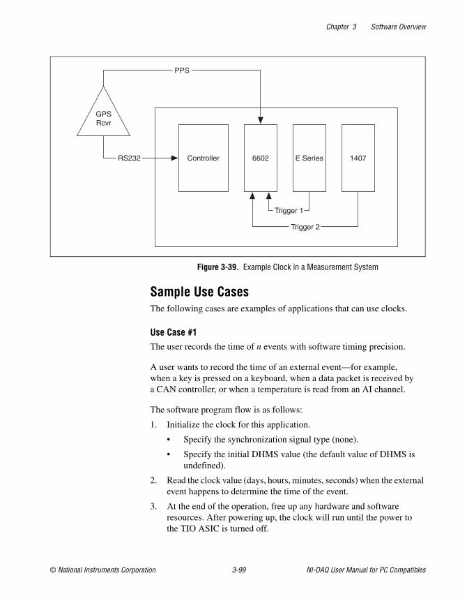
Chapter 3 Software Overview
© National Instruments Corporation 3-99 NI-DAQ User Manual for PC Compatibles
Figure 3-39. Example Clock in a Measurement System
Sample Use CasesThe following cases are examples of applications that can use clocks.
Use Case #1The user records the time of n events with software timing precision.
A user wants to record the time of an external event—for example,when a key is pressed on a keyboard, when a data packet is received bya CAN controller, or when a temperature is read from an AI channel.
The software program flow is as follows:
1. Initialize the clock for this application.
• Specify the synchronization signal type (none).
• Specify the initial DHMS value (the default value of DHMS isundefined).
2. Read the clock value (days, hours, minutes, seconds) when the externalevent happens to determine the time of the event.
3. At the end of the operation, free up any hardware and softwareresources. After powering up, the clock will run until the power tothe TIO ASIC is turned off.
Controller 6602 E Series 1407
Trigger 1
Trigger 2
GPSRcvr
RS232
PPS
Chapter 3 Software Overview
NI-DAQ User Manual for PC Compatibles 3-100 ni.com
Use Case #2The user records the time of a single event on two physically distributeddata acquisition systems with hardware timing precision.
A user wants to record how a lightning strike at a power grid in city Atravels to a grid station in city B. The lightning sensors in both citiesproduce a TTL pulse upon receiving the lightning bolt in city A.
Another user wants to correlate buffered analog input measurements acrossdistributed data acquisition systems. He connects a GPS receiver to anNI-TIO device on each system and connects the scan clock to the gate inputof the clock. The first active edge on the scan clock on each system willrecord the global time that sample was taken. The user can use the samplerate on each system to calculate the absolute time each sample was taken,assuming sample rates remain constant throughout the experiment.
The software program flow is as follows:
1. Initialize the clock for this application.
• Specify the synchronization signal source (PFI line, RTSI line).
• Specify the synchronization method.
– If source is PPS, read the current time from the GPS receivervia a serial port and set it as the initial DHMS value of theclock, or choose any arbitrary value. Initialization will takeabout 2 seconds.
– If source is IRIG-B, simply wait for 2 seconds afterprogramming the hardware. The clock will automaticallysynchronize to the GPS signal.
• Specify gate signal source and polarity.
• Clock value automatically latches upon receiving the first pulseon its gate input.
2. Poll the armed attribute of the clock until it is disarmed (when theexternal event happens). The clock is always armed in hardware, butthe software abstraction of the clock will be unarmed after it latchesthe first point.
3. Read the clock value (days, hours, minutes, seconds) to determine thetime of the external event.
4. At the end of the operation, free up any hardware and softwareresources. After powering up, the clock will run until the power tothe TIO ASIC is turned off.
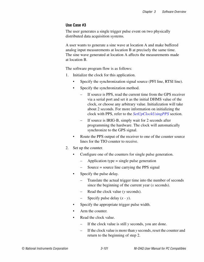
Chapter 3 Software Overview
© National Instruments Corporation 3-101 NI-DAQ User Manual for PC Compatibles
Use Case #3The user generates a single trigger pulse event on two physicallydistributed data acquisition systems.
A user wants to generate a sine wave at location A and make bufferedanalog input measurements at location B at precisely the same time.The sine wave generated at location A affects the measurements madeat location B.
The software program flow is as follows:
1. Initialize the clock for this application.
• Specify the synchronization signal source (PFI line, RTSI line).
• Specify the synchronization method.
– If source is PPS, read the current time from the GPS receivervia a serial port and set it as the initial DHMS value of theclock, or choose any arbitrary value. Initialization will takeabout 2 seconds. For more information on initializing theclock with PPS, refer to the SetUpClockUsingPPS section.
– If source is IRIG-B, simply wait for 2 seconds afterprogramming the hardware. The clock will automaticallysynchronize to the GPS signal.
• Route the PPS output of the receiver to one of the counter sourcelines for the TIO counter to receive.
2. Set up the counter.
• Configure one of the counters for single pulse generation.
– Application type = single pulse generation
– Source = source line carrying the PPS signal
• Specify the pulse delay.
– Translate the actual trigger time into the number of secondssince the beginning of the current year (x seconds).
– Read the clock value (y seconds).
– Specify pulse delay (x - y).
• Specify the appropriate trigger pulse width.
• Arm the counter.
• Read the clock value.
– If the clock value is still y seconds, you are done.
– If the clock value is more than y seconds, reset the counter andreturn to the beginning of step 2.
Chapter 3 Software Overview
NI-DAQ User Manual for PC Compatibles 3-102 ni.com
• Configure analog input (analog output) operation to trigger uponreceiving a pulse on the counter output.
• Counter produces a pulse when the clock value reaches the desiredtime interval.
3. Poll the armed attribute of the counter until it is disarmed, when thecounter has generated the trigger pulse.
4. At the end of the operation, free up any hardware and softwareresources. After powering up, the clock will run until the power tothe TIO ASIC is turned off.
RTSI Bus Trigger FunctionsThe Real-Time System Integration (RTSI) Bus Trigger functions connectand disconnect signals over the RTSI bus trigger lines.
Refer to the NI-DAQ Function Reference Online Help file to determinewhich functions your device supports.
RTSI_Clear Disconnects all RTSI bus trigger lines fromsignals on the specified device.
RTSI_Clock Connects or disconnects the system clock fromthe RTSI bus.
RTSI_Conn Connects a device signal to the specified RTSIbus trigger line.
RTSI_DisConn Disconnects a device signal from the specifiedRTSI bus trigger line.
Select_Signal Connects or disconnects a device signal to aRTSI bus trigger line.
Refer to the NI-DAQ Function Reference Online Help file to determine ifyour device supports RTSI.
RTSI BusThe RTSI bus is implemented via a 34-pin ribbon cable connector onthe AT, NEC, PCI E Series, PCI-DSA, and 671X devices. The RTSI busis implemented on VXI-DAQ devices using the VXIbus trigger lines.On PXI DAQ and DSA devices, the RTSI bus is implemented usingPXI trigger bus lines. On 1394 E Series DAQ devices, the RTSI bus isimplemented with a 15-pin mini-DSUB connector. The RTSI bus has a
Chapter 3 Software Overview
© National Instruments Corporation 3-103 NI-DAQ User Manual for PC Compatibles
7-wire trigger bus. Each device that works with a RTSI bus interfacecontains a number of useful signals that can be driven onto, or receivedfrom, the trigger lines. Each device is equipped with a switch with whichan onboard signal is connected to any one of the RTSI bus trigger linesthrough software control. By programming one device to drive a particulartrigger line and another device to receive from the same trigger line, youcan hardware connect the two devices. Use the RTSI Bus Trigger functionsdescribed in this chapter for this type of programmable signalinterconnection between devices.
Through the RTSI bus, you can trigger one device from another device,share clocks and signals between devices, and synchronize devices to thesame signals. The RTSI bus also can connect signals on a single device.
To specify the signals on each device that you can connect to the RTSI bustrigger lines, each device signal is assigned a signal code number. Make allreferences to that signal by using the signal code number in the RTSI bustrigger function calls. The signal codes for each device that can use theRTSI bus trigger lines are outlined later in this section.
Each signal listed in this chapter also has a signal direction. If a signal islisted with a source direction, that signal can drive the trigger lines. If asignal is listed with a receiver direction, that signal must be received fromthe trigger lines. A bidirectional signal direction means that the signal canact as either a source or a receiver, depending on the application.
E Series, DSA, 660X, and 671X RTSI ConnectionsFor information regarding signals on the E Series, DSA, 660X, and671X devices that you can connect to the RTSI bus, refer to theSelect_Signal function description in the NI-DAQ Function ReferenceOnline Help file.
Note If you have a PXI-DSA board in slot 2 (star trigger controller slot), do not drive anysignals on RTSI 6 from other modules in the chassis. You can use other RTSI lines.
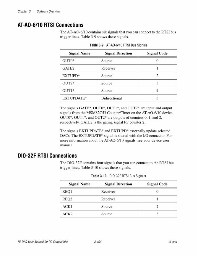
Chapter 3 Software Overview
NI-DAQ User Manual for PC Compatibles 3-104 ni.com
AT-AO-6/10 RTSI ConnectionsThe AT-AO-6/10 contains six signals that you can connect to the RTSI bustrigger lines. Table 3-9 shows these signals.
The signals GATE2, OUT0*, OUT1*, and OUT2* are input and outputsignals from the MSM82C53 Counter/Timer on the AT-AO-6/10 device.OUT0*, OUT1*, and OUT2* are outputs of counters 0, 1, and 2,respectively. GATE2 is the gating signal for counter 2.
The signals EXTUPDATE* and EXTUPD* externally update selectedDACs. The EXTUPDATE* signal is shared with the I/O connector. Formore information about the AT-AO-6/10 signals, see your device usermanual.
DIO-32F RTSI ConnectionsThe DIO-32F contains four signals that you can connect to the RTSI bustrigger lines. Table 3-10 shows these signals.
Table 3-9. AT-AO-6/10 RTSI Bus Signals
Signal Name Signal Direction Signal Code
OUT0* Source 0
GATE2 Receiver 1
EXTUPD* Source 2
OUT2* Source 3
OUT1* Source 4
EXTUPDATE* Bidirectional 5
Table 3-10. DIO-32F RTSI Bus Signals
Signal Name Signal Direction Signal Code
REQ1 Receiver 0
REQ2 Receiver 1
ACK1 Source 2
ACK2 Source 3
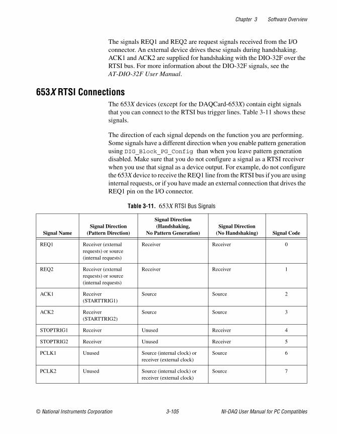
Chapter 3 Software Overview
© National Instruments Corporation 3-105 NI-DAQ User Manual for PC Compatibles
The signals REQ1 and REQ2 are request signals received from the I/Oconnector. An external device drives these signals during handshaking.ACK1 and ACK2 are supplied for handshaking with the DIO-32F over theRTSI bus. For more information about the DIO-32F signals, see theAT-DIO-32F User Manual.
653X RTSI ConnectionsThe 653X devices (except for the DAQCard-653X) contain eight signalsthat you can connect to the RTSI bus trigger lines. Table 3-11 shows thesesignals.
The direction of each signal depends on the function you are performing.Some signals have a different direction when you enable pattern generationusing DIG_Block_PG_Config than when you leave pattern generationdisabled. Make sure that you do not configure a signal as a RTSI receiverwhen you use that signal as a device output. For example, do not configurethe 653X device to receive the REQ1 line from the RTSI bus if you are usinginternal requests, or if you have made an external connection that drives theREQ1 pin on the I/O connector.
Table 3-11. 653X RTSI Bus Signals
Signal NameSignal Direction
(Pattern Direction)
Signal Direction(Handshaking,
No Pattern Generation)Signal Direction
(No Handshaking) Signal Code
REQ1 Receiver (externalrequests) or source(internal requests)
Receiver Receiver 0
REQ2 Receiver (externalrequests) or source(internal requests)
Receiver Receiver 1
ACK1 Receiver(STARTTRIG1)
Source Source 2
ACK2 Receiver(STARTTRIG2)
Source Source 3
STOPTRIG1 Receiver Unused Receiver 4
STOPTRIG2 Receiver Unused Receiver 5
PCLK1 Unused Source (internal clock) orreceiver (external clock)
Source 6
PCLK2 Unused Source (internal clock) orreceiver (external clock)
Source 7
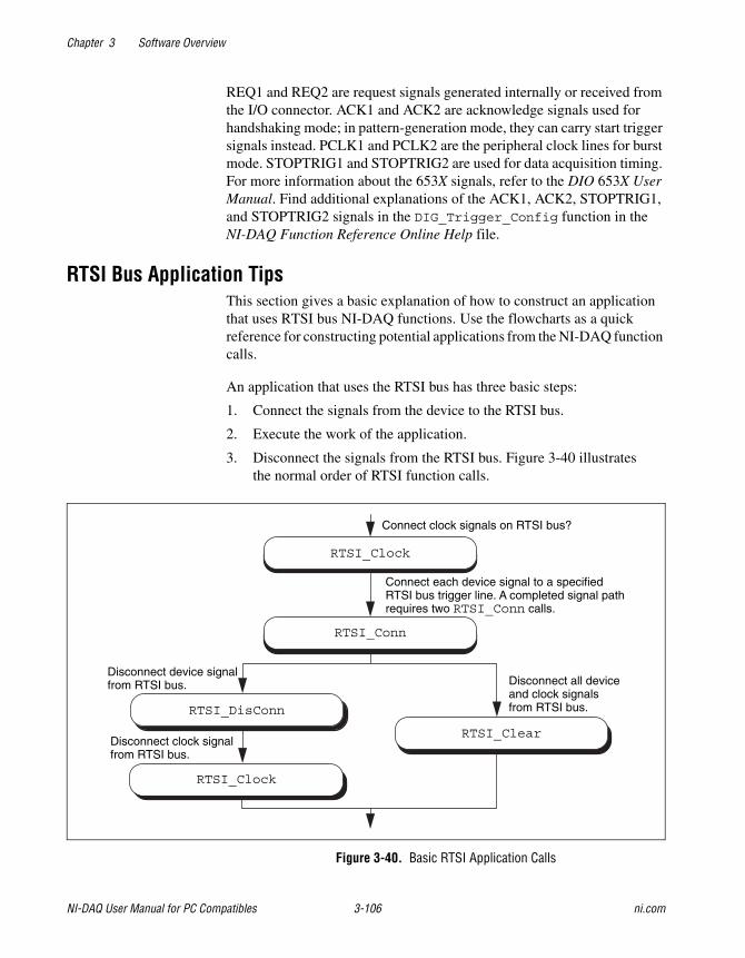
Chapter 3 Software Overview
NI-DAQ User Manual for PC Compatibles 3-106 ni.com
REQ1 and REQ2 are request signals generated internally or received fromthe I/O connector. ACK1 and ACK2 are acknowledge signals used forhandshaking mode; in pattern-generation mode, they can carry start triggersignals instead. PCLK1 and PCLK2 are the peripheral clock lines for burstmode. STOPTRIG1 and STOPTRIG2 are used for data acquisition timing.For more information about the 653X signals, refer to the DIO 653X UserManual. Find additional explanations of the ACK1, ACK2, STOPTRIG1,and STOPTRIG2 signals in the DIG_Trigger_Config function in theNI-DAQ Function Reference Online Help file.
RTSI Bus Application TipsThis section gives a basic explanation of how to construct an applicationthat uses RTSI bus NI-DAQ functions. Use the flowcharts as a quickreference for constructing potential applications from the NI-DAQ functioncalls.
An application that uses the RTSI bus has three basic steps:
1. Connect the signals from the device to the RTSI bus.
2. Execute the work of the application.
3. Disconnect the signals from the RTSI bus. Figure 3-40 illustratesthe normal order of RTSI function calls.
Figure 3-40. Basic RTSI Application Calls
Connect clock signals on RTSI bus?
RTSI_Clock
RTSI_Conn
Disconnect all deviceand clock signalsfrom RTSI bus.
RTSI_Clear
Disconnect device signalfrom RTSI bus.
Disconnect clock signalfrom RTSI bus.
RTSI_DisConn
RTSI_Clock
Connect each device signal to a specifiedRTSI bus trigger line. A completed signal pathrequires two RTSI_Conn calls.
Chapter 3 Software Overview
© National Instruments Corporation 3-107 NI-DAQ User Manual for PC Compatibles
Call RTSI_Clock/RTSI_Conn to connect the signals. Each completedsignal path requires RTSI_Conn calls. The first call specifies the devicesignal to transmit onto a RTSI bus trigger line. The second call specifiesthe device signal that receives a RTSI bus trigger line. After the signalsare connected, you are ready to do the actual work of your application.
After you finish with the RTSI bus, disconnect the device from the bus.To do this, call RTSI_DisConn/RTSI_Clock for each connection made.Alternatively, call RTSI_Clear to sever all connections from your deviceto the RTSI bus.
SCXI FunctionsRefer to the NI-DAQ Function Reference Online Help file to determinewhich functions your device supports.
SCXI_AO_Write Sets the DAC channel on theSCXI-1124 module to the specifiedvoltage or current output value. Youalso can use this function to write abinary value directly to the DACchannel, or to translate a voltage orcurrent value to the correspondingbinary value.
SCXI_Cal_Constants Calculates calibration constants for theparticular channel and range or gainusing measured voltage/binary pairs.You can use this function with anySCXI analog input or analog outputmodule. The constants can be storedand retrieved from NI-DAQ memory orthe module EEPROM (if your modulehas an EEPROM). The driver uses thecalibration constants to scale analoginput data more accurately when youuse the SCXI_Scale function andoutput data when you useSCXI_AO_Write.
SCXI_Calibrate Provides a single call calibration for theSCXI-1112, SCXI-1125, SCXI-1520,and SCXI-1540 modules. With theSCXI-1112 and SCXI-1125, calling

Chapter 3 Software Overview
NI-DAQ User Manual for PC Compatibles 3-108 ni.com
this function calibrates individualchannels. However, with theSCXI-1540, calling this functioncalibrates every channel. You alsouse this function to update the actualonboard reference voltage value onthe SCXI-1125 EEPROM and to copycalibration constants to the module’sdefault EEPROM load area fromanother EEPROM area or fromNI-DAQ memory.
SCXI_Calibrate_Setup Grounds the amplifier inputs of anSCXI-1100, SCXI-1101, SCXI-1122,or SCXI-1141, SCXI-1142, orSCXI-1143 so that you can determinethe amplifier offset. You also can usethis function to switch a shunt resistoracross your bridge circuit to test thecircuit. This function supports shuntcalibration for the SCXI-1122 moduleor the SCXI-1121 module with theSCXI-1321 terminal block. It alsosupports shunt calibration for theSCXI-1520 module with theSCXI-1314 terminal block.
SCXI_Change_Chan Selects a new channel of a multiplexedmodule that has previously been set upfor a single-channel operation using theSCXI_Single_Chan_Setup function.
SCXI_Configure_Connection Sets the connection type parameter toa specified type on a given channel orall channels on the SCXI-1520 andSCXI-1540 modules. This functionalso allows programmatic control ofexternal synchronization.
SCXI_Configure_Filter Sets the specified channel to theassigned filter setting on any SCXImodule with programmable filtersettings.
Chapter 3 Software Overview
© National Instruments Corporation 3-109 NI-DAQ User Manual for PC Compatibles
SCXI_Get_Chassis_Info Returns chassis configurationinformation.
SCXI_Get_Module_Info Returns configuration information forthe assigned SCXI chassis slot number.
SCXI_Get_State Gets the state of a single channel or anentire port on any digital or relaymodule.
SCXI_Get_Status Reads the data in the status registeron the specified module. You can usethis function with the SCXI-1160 orSCXI-1122 to determine if the relayshave finished switching, with theSCXI-1124 to determine if the DACshave settled, with the SCXI-1126 todetermine if the module has settledafter changing any of its programmablefunctions (ranges, filter settings,threshold, or hysteresis), or with theSCXI-1102/B/C to determine if themodule has settled after changinggains.
SCXI_Load_Config Loads the SCXI chassis configurationinformation that you established in theMeasurement & Automation Explorer.Sets the software states of the chassisand modules present to their defaultstates. No changes are made to thehardware states of the SCXI chassisor modules.
SCXI_ModuleID_Read Reads the Module ID register ofthe SCXI module in a given slot.The principal differencebetween this function andSCXI_Get_Module_Info isthat SCXI_ModuleID_Read doesa hardware read of the module. Youcan use this function to verify thatyour SCXI system is configuredand communicating properly.
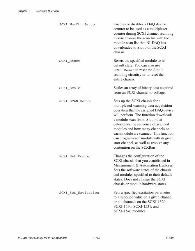
Chapter 3 Software Overview
NI-DAQ User Manual for PC Compatibles 3-110 ni.com
SCXI_MuxCtr_Setup Enables or disables a DAQ devicecounter to be used as a multiplexercounter during SCXI channel scanningto synchronize the scan list with themodule scan list that NI-DAQ hasdownloaded to Slot 0 of the SCXIchassis.
SCXI_Reset Resets the specified module to itsdefault state. You can also useSCXI_Reset to reset the Slot 0scanning circuitry or to reset theentire chassis.
SCXI_Scale Scales an array of binary data acquiredfrom an SCXI channel to voltage.
SCXI_SCAN_Setup Sets up the SCXI chassis for amultiplexed scanning data acquisitionoperation that the assigned DAQ devicewill perform. The function downloadsa module scan list to Slot 0 thatdetermines the sequence of scannedmodules and how many channels oneach module are scanned. This functioncan program each module with its givenstart channel, as well as resolve anycontention on the SCXIbus.
SCXI_Set_Config Changes the configuration of theSCXI chassis that you established inMeasurement & Automation Explorer.Sets the software states of the chassisand modules specified to their defaultstates. Does not change the SCXIchassis or module hardware states.
SCXI_Set_Excitation Sets a specified excitation parameterto a supplied value on a given channelor all channels on the SCXI-1520,SCXI-1530, SCXI-1531, andSCXI-1540 modules.
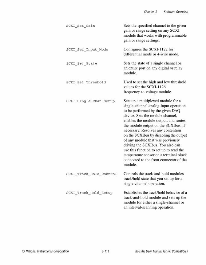
Chapter 3 Software Overview
© National Instruments Corporation 3-111 NI-DAQ User Manual for PC Compatibles
SCXI_Set_Gain Sets the specified channel to the givengain or range setting on any SCXImodule that works with programmablegain or range settings.
SCXI_Set_Input_Mode Configures the SCXI-1122 fordifferential mode or 4-wire mode.
SCXI_Set_State Sets the state of a single channel oran entire port on any digital or relaymodule.
SCXI_Set_Threshold Used to set the high and low thresholdvalues for the SCXI-1126frequency-to-voltage module.
SCXI_Single_Chan_Setup Sets up a multiplexed module for asingle-channel analog-input operationto be performed by the given DAQdevice. Sets the module channel,enables the module output, and routesthe module output on the SCXIbus, ifnecessary. Resolves any contentionon the SCXIbus by disabling the outputof any module that was previouslydriving the SCXIbus. You also canuse this function to set up to read thetemperature sensor on a terminal blockconnected to the front connector of themodule.
SCXI_Track_Hold_Control Controls the track-and-hold modulestrack/hold state that you set up for asingle-channel operation.
SCXI_Track_Hold_Setup Establishes the track/hold behavior of atrack-and-hold module and sets up themodule for either a single-channel oran interval-scanning operation.

Chapter 3 Software Overview
NI-DAQ User Manual for PC Compatibles 3-112 ni.com
SCXI Application TipsThere are three categories of SCXI applications—analog inputapplications, analog output applications, and digital applications.
Figure 3-41 shows the basic structure of an SCXI application.
Figure 3-41. General SCXIbus Application
The figures in the following sections show the detailed call sequencesfor different types of SCXI operations. In effect, each of the remainingflowcharts in this section is an enlargement of the Analog Input Operations,the Analog Output Operations, or the Digital Operations node inFigure 3-41. Please refer to the function descriptions in the NI-DAQFunction Reference Online Help file for detailed information abouteach function used in the flowcharts.
You can divide the SCXI analog input applications further into twocategories—single-channel applications and channel-scanning
Load SCXI configuration that was entered in theMeasurement & Automation Explorer and initializesoftware defaults.
SCXI_Load_Config
SCXI_Reset
SCXI_Reset
Analog Input Operations Digital Operations
Done?
Yes
No
Reset the chassis and modules totheir default hardware settings.
Reset the chassis and modules totheir default hardware settings.
Analog Output Operations
Chapter 3 Software Overview
© National Instruments Corporation 3-113 NI-DAQ User Manual for PC Compatibles
applications. The distinction between the two categories is simple—single-channel applications do not involve automatic channel switchingby the hardware during an analog input process; channel-scanningapplications do.
After you have set up the SCXI system, single-channel applications usethe AI or the DAQ class of functions described earlier in this chapter toacquire the input data. To acquire data from more than one channel, youneed multiple AI or DAQ function calls, and you might need explicit SCXIfunction calls to change the selected SCXI channel; this specific type ofsingle-channel application is called software scanning.
After you have set up the SCXI system, channel-scanning applications usethe SCAN and Lab_ISCAN classes of functions described earlier in thischapter to acquire the input data.
Building Analog Input Applications inMultiplexed ModeMultiplexed applications require the use of SCXI functions to selectthe multiplexed channels, select the programmable module features,route signals on the SCXIbus, and program Slot 0. After you have setup the SCXI chassis and modules, you can use the AI, DAQ, SCAN, andLab_ISCAN functions to acquire the data either with a plug-in DAQ deviceor the SCXI-1200. The channel parameter that is passed to each of thesefunctions is almost always 0 because the multiplexed output of a moduleis connected by default to analog input channel 0 of the DAQ device orSCXI-1200. If you are using a PXI DAQ device with an internal connectionto the PXI-1010 or PXI-1011 SCXIbus, then ND_PXI_SC is the channelparameter. When you use multiple chassis, the modules in each chassis aremultiplexed to a separate analog input channel. In that case, the channelparameters of the AI, DAQ, SCAN, and Lab_ISCAN functions should be theDAQ device channel that corresponds to the chassis you want for theoperation. You cannot use the SCXI-1200 with multiple chassis.
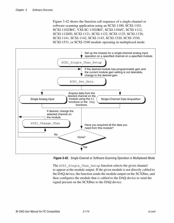
Chapter 3 Software Overview
NI-DAQ User Manual for PC Compatibles 3-114 ni.com
Figure 3-42 shows the function call sequence of a single-channel orsoftware-scanning application using an SCXI-1100, SCXI-1101,SCXI-1102/B/C, VXI-SC-1102/B/C, SCXI-1104/C, SCXI-1112,SCXI-1120/D, SCXI-1121, SCXI-1122, SCXI-1125, SCXI-1126,SCXI-1141, SCXI-1142, SCXI-1143, SCXI-1520, SCXI-1530,SCXI-1531, or SCXI-1540 module operating in multiplexed mode.
Figure 3-42. Single-Channel or Software-Scanning Operation in Multiplexed Mode
The SCXI_Single_Chan_Setup function selects the given channelto appear at the module output. If the given module is not directly cabled tothe DAQ device, the function sends the module output on the SCXIbus, andthen configures the module that is cabled to the DAQ device to send thesignal present on the SCXIbus to the DAQ device.
SCXI_Change_Chan
SCXI_Single_Chan_Setup
Done?
SCXI_Set_Gain
Have you acquired all the data youneed from this module?
Yes
No
If desired, change theselected channel onthe module.
Acquire data from thedesired channel on themodule using the AIfunctions or the DAQ
functions.
Single Analog Input Single-Channel Data Acquisition
If the desired module has programmable gain andthe current module gain setting is not desirable,change to the desired gain.
Set up the chassis for a single-channel analog inputoperation on a specified channel on a specified module.
Chapter 3 Software Overview
© National Instruments Corporation 3-115 NI-DAQ User Manual for PC Compatibles
The SCXI_Set_Gain function changes the gain or range of theSCXI-1100, SCXI-1102/B/C, VXI-SC-1102/B/C, SCXI-1122,SCXI-1125, SCXI-1126, SCXI-1141, SCXI-1142, SCXI-1143,SCXI-1520, SCXI-1530, SCXI-1531, or SCXI-1540 module. The modulemaintains this gain or range setting until you call the function again tochange it. You can also do any other module-specific programming at thispoint, such as SCXI_Configure_Filter or SCXI_Set_Input_Mode.
To achieve software scanning, select a different channel on the moduleusing the SCXI_Change_Chan function after acquiring data from thechannel you want with the AI or DAQ functions. If you want a channel ona different module, call the SCXI_Single_Chan_Setup function againto enable the appropriate module outputs and manage the SCXIbus signalrouting.
Figure 3-43 shows the function call sequence of a single channel orsoftware-scanning application using a Simultaneous Sample and Hold(SSH) module in multiplexed mode.
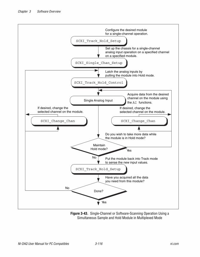
Chapter 3 Software Overview
NI-DAQ User Manual for PC Compatibles 3-116 ni.com
Figure 3-43. Single-Channel or Software-Scanning Operation Using aSimultaneous Sample and Hold Module in Multiplexed Mode
Single Analog Input
Yes
No
Have you acquired all the datayou need from this module?
Acquire data from the desiredchannel on the module usingthe AI functions.
SCXI_Track_Hold_Control
SCXI_Track_Hold_Setup
SCXI_Track_Hold_Setup
MaintainHold mode?
Done?
Do you wish to take more data whilethe module is in Hold mode?
If desired, change theselected channel on the module.
Yes
No
Put the module back into Track modeto sense the new input values.
If desired, change theselected channel on the module.
SCXI_Change_Chan SCXI_Change_Chan
Configure the desired modulefor a single-channel operation.
Set up the chassis for a single-channelanalog input operation on a specified channelon a specified module.
Latch the analog inputs byputting the module into Hold mode.
SCXI_Single_Chan_Setup
Chapter 3 Software Overview
© National Instruments Corporation 3-117 NI-DAQ User Manual for PC Compatibles
Notice the similarities between Figure 3-43 and Figure 3-44,which shows the corresponding application in parallel mode. TheSCXI_Track_Hold_Setup calls and the SCXI_Track_Hold_Controlcalls are the same. In multiplexed mode, however, anSCXI_Single_Chan_Setup call is required to select themultiplexed channel and appropriately route the output to the DAQ deviceor SCXI-1200 module. The SCXI_Change_Chan call can change thechannel on the module either while the module is in hold mode or afterthe module has been returned to track mode.
Figure 3-43 shows the function call sequence of a channel-scanningapplication in multiplexed mode. Remember that only the MIO andAI devices, the Lab-PC+, the SCXI-1200, and the DAQCard-1200work with channel scanning in multiplexed mode. You can use anycombination of module types in a scanning operation. If any track-and-holdmodules are to be scanned, use interval scanning; if you are using a plug-inDAQ device, the module directly connected to the DAQ device must beone of the SSH modules.
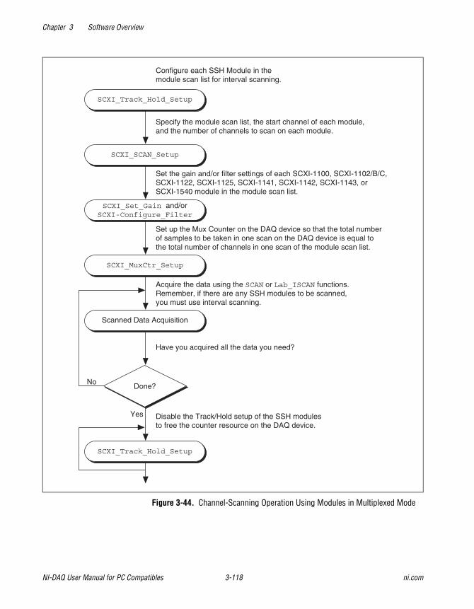
Chapter 3 Software Overview
NI-DAQ User Manual for PC Compatibles 3-118 ni.com
Figure 3-44. Channel-Scanning Operation Using Modules in Multiplexed Mode
SCXI_Track_Hold_Setup
SCXI_SCAN_Setup
SCXI_Set_Gain and/orSCXI-Configure_Filter
SCXI_MuxCtr_Setup
Scanned Data Acquisition
SCXI_Track_Hold_Setup
Done?
Configure each SSH Module in themodule scan list for interval scanning.
Specify the module scan list, the start channel of each module,and the number of channels to scan on each module.
Set the gain and/or filter settings of each SCXI-1100, SCXI-1102/B/C,SCXI-1122, SCXI-1125, SCXI-1141, SCXI-1142, SCXI-1143, orSCXI-1540 module in the module scan list.
Set up the Mux Counter on the DAQ device so that the total numberof samples to be taken in one scan on the DAQ device is equal tothe total number of channels in one scan of the module scan list.
Acquire the data using the SCAN or Lab_ISCAN functions.Remember, if there are any SSH modules to be scanned,you must use interval scanning.
Have you acquired all the data you need?
Disable the Track/Hold setup of the SSH modulesto free the counter resource on the DAQ device.
Yes
No
Chapter 3 Software Overview
© National Instruments Corporation 3-119 NI-DAQ User Manual for PC Compatibles
If any of the modules to be scanned are SSH modules, you must establishthe Track/Hold setup of each one. To synchronize multiple SSH modules,you can configure the module that is receiving the Track/Hold controlsignal to send the Track/Hold signal on the SCXIbus so that any other SSHmodule can use it. The Track/Hold signal can be from either the DAQdevice counter or an external source.
The SCXI_SCAN_Setup call establishes the module scan list, whichNI-DAQ downloads to Slot 0. Each module is programmed for automaticscanning starting at its given start channel. If you need the SCXIbus duringthe scan to route the outputs of multiple modules, this function resolves anycontention. If you are using an SCXI-1200, you can include the SCXI-1200in the module scan list.
In many of the data acquisition function descriptions in the NI-DAQFunction Reference Online Help file, the count parameter descriptionsspecify that count must be an integer multiple of the total number ofchannels scanned. In channel-scanning acquisitions in multiplexed mode,the total number of channels scanned is the sum of all the elements in thenumChans array in the SCXI_SCAN_Setup function call.
If any of the modules in the module scan list are SCXI-1100,SCXI-1102/B/C, VXI-SC-1102/B/C, SCXI-1122, SCXI-1125,SCXI-1126, SCXI-1141, SCXI-1142, SCXI-1143, SCXI-1520,SCXI-1530, SCXI-1531, or SCXI-1540 modules, you can useSCXI_Set_Gain to change the gain or range setting on each module.You also can use the SCXI_Configure_Filter function for theSCXI-1122, SCXI-1125, SCXI-1126, SCXI-1141, SCXI-1142, andSCXI-1143, SCXI-1530, SCXI-1531, and the SCXI_Set_Input_Modefunction for the SCXI-1122.
The SCXI_MuxCtr_Setup call synchronizes the module scan list with theDAQ device or SCXI-1200 scan list. In most cases (especially when usinginterval scanning), it is best to ensure that the number of samples NI-DAQtakes in one pass through the module scan list is the same as the numberof samples NI-DAQ takes in one pass through the DAQ device scan list.Please refer to the SCXI_MuxCtr_Setup function description in theNI-DAQ Function Reference Online Help file.
After you have set up the SCXI chassis and modules, you can perform morethan one channel-scanning operation using the SCAN or Lab_ISCANfunctions without reconfiguring the SCXI chassis or modules.
Chapter 3 Software Overview
NI-DAQ User Manual for PC Compatibles 3-120 ni.com
When you are using the SCXI-1200 to acquire the data, pass channel 0 tothe Lab_ISCAN functions; the SCXI Slot 0 takes care of all the channelswitching.
Building Analog Input Applications in Parallel ModeWhen you operate the SCXI-1120/D, SCXI-1121, SCXI-1125,SCXI-1126, SCXI-1141, SCXI-1142, and SCXI-1143 modules in parallelmode, you need no further SCXI function calls beyond those shown inFigure 3-43 to set up the modules for analog input operations. After youhave initialized and reset the SCXI chassis and modules, you can use theAI, DAQ, SCAN, or Lab_ISCAN functions with the DAQ device. Rememberthat the channel and gain parameters of the AI, DAQ, SCAN, andLab_ISCAN functions refer to the DAQ device channels and gains.
For example, to acquire a single reading from channel 0 on the module,call the AI_Read function with the channel parameter set to 0. Thegain parameter refers to the DAQ device gain. You then can use theSCXI_Scale function to convert the binary reading to a voltage. TheAI_VRead function call is not generally useful in SCXI applicationsbecause it does not take into account the gain applied at the SCXI modulewhen scaling the binary reading.
To build a channel-scanning application using the SCXI-1120/D,SCXI-1121, SCXI-1125, SCXI-1126, SCXI-1141, SCXI-1142, orSCXI-1143 in parallel mode, use the SCAN and Lab_ISCAN functions toscan the channels on the DAQ device that correspond to channels on themodule you want. For example, to scan channels 0, 1, and 3 on the moduleusing an MIO-16 device, call the SCAN_Op function with the channelvector set to 0, 1, 3. The gain vector should contain the MIO and AIdevice channel gains. After the data is acquired, you can demultiplexit and send the data for each channel to the DAQ_VScale function.Remember to pass the total gain to the DAQ_VScale function to obtainthe voltage read at the module input.
In many of the data acquisition function descriptions in the NI-DAQFunction Reference Online Help file, the count parameter descriptionsspecify that count must be an integer multiple of the total number ofchannels scanned. In channel-scanning acquisitions in parallel mode,the total number of channels scanned is the numChans parameter inthe SCAN_Setup, SCAN_Op, SCAN_to_Disk, Lab_ISCAN_Start, Lab_ISCAN_Op, or Lab_ISCAN_to_Disk function calls.
Chapter 3 Software Overview
© National Instruments Corporation 3-121 NI-DAQ User Manual for PC Compatibles
When you use the SCXI-1200 module in parallel mode, you simply use theAI, DAQ, or Lab_ISCAN functions described earlier in this chapter withthe logical device number you assigned in Measurement & AutomationExplorer. You cannot use the SCXI-1200 to read channels from otheranalog input modules that are configured for parallel mode.
The SCXI-1100, SCXI-1101, SCXI-1102/B/C, VXI-SC-1102/B/C,SCXI-1104/C, SCXI-1112, SCXI-1122, and SCXI-1540 operate inmultiplexed mode only.
The SCXI-1140, SCXI-1520, SCXI-1530, and SCXI-1531 modulesrequire the use of SCXI functions to configure and control the Track/Holdstate of the module before you can use the AI, DAQ, SCAN, and Lab_ISCANfunctions to acquire the data. Figure 3-45 shows the function call sequenceof a single-channel (or software-scanning) operation using these modulesin parallel mode.
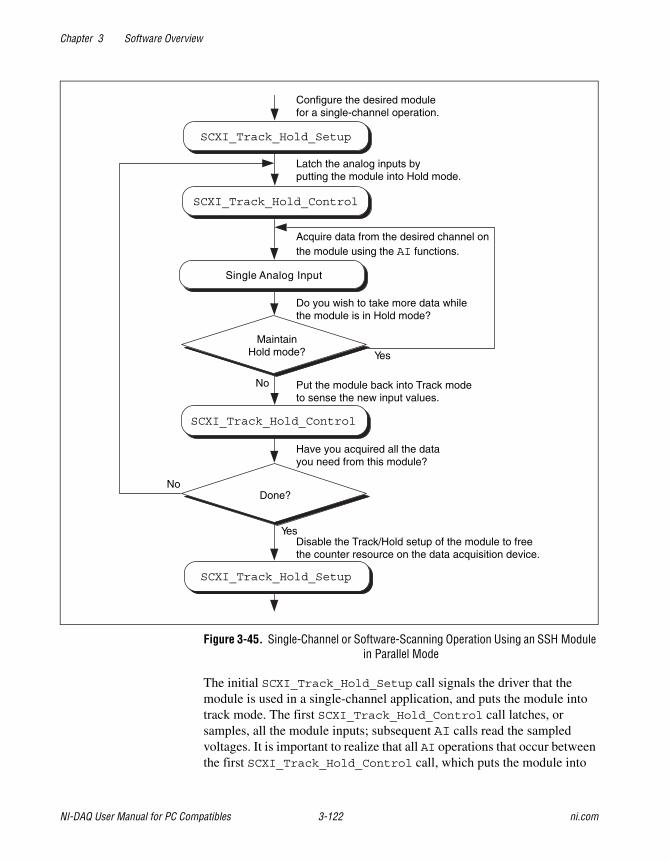
Chapter 3 Software Overview
NI-DAQ User Manual for PC Compatibles 3-122 ni.com
Figure 3-45. Single-Channel or Software-Scanning Operation Using an SSH Modulein Parallel Mode
The initial SCXI_Track_Hold_Setup call signals the driver that themodule is used in a single-channel application, and puts the module intotrack mode. The first SCXI_Track_Hold_Control call latches, orsamples, all the module inputs; subsequent AI calls read the sampledvoltages. It is important to realize that all AI operations that occur betweenthe first SCXI_Track_Hold_Control call, which puts the module into
Single Analog Input
Yes
No
Have you acquired all the datayou need from this module?
Acquire data from the desired channel onthe module using the AI functions.
SCXI_Track_Hold_Control
SCXI_Track_Hold_Control
MaintainHold mode?
Done?
SCXI_Track_Hold_Setup
Do you wish to take more data whilethe module is in Hold mode?
Yes
No
Put the module back into Track modeto sense the new input values.
Configure the desired modulefor a single-channel operation.
Latch the analog inputs byputting the module into Hold mode.
SCXI_Track_Hold_Setup
Disable the Track/Hold setup of the module to freethe counter resource on the data acquisition device.
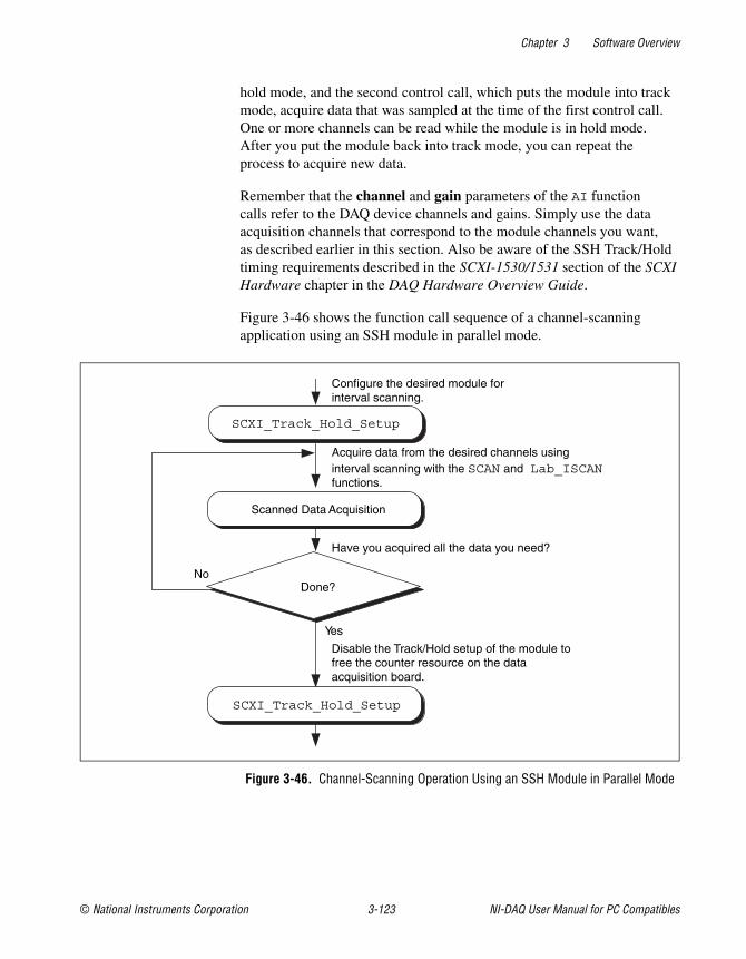
Chapter 3 Software Overview
© National Instruments Corporation 3-123 NI-DAQ User Manual for PC Compatibles
hold mode, and the second control call, which puts the module into trackmode, acquire data that was sampled at the time of the first control call.One or more channels can be read while the module is in hold mode.After you put the module back into track mode, you can repeat theprocess to acquire new data.
Remember that the channel and gain parameters of the AI functioncalls refer to the DAQ device channels and gains. Simply use the dataacquisition channels that correspond to the module channels you want,as described earlier in this section. Also be aware of the SSH Track/Holdtiming requirements described in the SCXI-1530/1531 section of the SCXIHardware chapter in the DAQ Hardware Overview Guide.
Figure 3-46 shows the function call sequence of a channel-scanningapplication using an SSH module in parallel mode.
Figure 3-46. Channel-Scanning Operation Using an SSH Module in Parallel Mode
SCXI_Track_Hold_Setup
Acquire data from the desired channels usinginterval scanning with the SCAN and Lab_ISCANfunctions.
Yes
Have you acquired all the data you need?
No
Configure the desired module forinterval scanning.
Disable the Track/Hold setup of the module tofree the counter resource on the dataacquisition board.
Scanned Data Acquisition
Done?
SCXI_Track_Hold_Setup
Chapter 3 Software Overview
NI-DAQ User Manual for PC Compatibles 3-124 ni.com
The call sequence is much simpler because the scan interval timerautomatically controls the Track/Hold state of the module during theinterval-scanning operation. Remember that only the MIO and AI devices,Lab-PC+, PCI-1200, SCXI-1200, and DAQCard-1200 devices work withchannel-scanning using tan SSH module.
SCXI Data Acquisition RatesThe settling time of the SCXI modules can affect the maximum dataacquisition rates that your DAQ device can achieve. The settling times ofthe different SCXI modules at each gain setting are listed in Table 3-12 forthree different DAQ devices.
The maximum data acquisition rate you can use will be the inverse of thesettling time for your SCXI module and DAQ device. For example, if thesettling time is listed as 7 µs, your maximum data acquisition rate will be1/7 µs = 143 kS/s.
If you are using a DAQ device with a maximum acquisition rate fasterthan the AT-MIO-16E-2 (such as the PCI-MIO-16E-1), you should use thesettling times and corresponding maximum acquisition rates listed for theAT-MIO-16E-2.
If you are using a DAQ device with a maximum acquisition rate slower than200 kS/s (such as the PCI-6032E), you should add 1 µs to the settling timeof your DAQ device. The maximum acquisition rate for the PCI-6032Ewould be 1/(10 µs + 1 µs) = 90.9 kS/s.
If you are using a DAQ device faster than 200 kS/s but slower than theAT-MIO-16E-2 (such as an AT-MIO-64E-3), you can interpolate betweenthe settling times listed for these devices to calculate an appropriate settlingtime and corresponding maximum data acquisition rate.
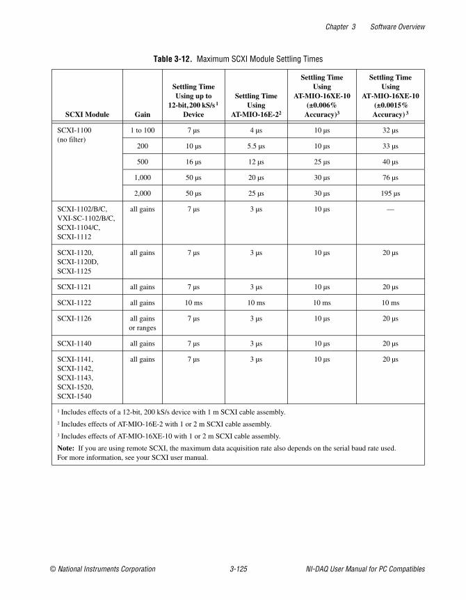
Chapter 3 Software Overview
© National Instruments Corporation 3-125 NI-DAQ User Manual for PC Compatibles
Table 3-12. Maximum SCXI Module Settling Times
SCXI Module Gain
Settling TimeUsing up to
12-bit,200 kS/s 1
Device
Settling TimeUsing
AT-MIO-16E-22
Settling TimeUsing
AT-MIO-16XE-10(±0.006%
Accuracy)3
Settling TimeUsing
AT-MIO-16XE-10(±0.0015%Accuracy) 3
SCXI-1100(no filter)
1 to 100 7 µs 4 µs 10 µs 32 µs
200 10 µs 5.5 µs 10 µs 33 µs
500 16 µs 12 µs 25 µs 40 µs
1,000 50 µs 20 µs 30 µs 76 µs
2,000 50 µs 25 µs 30 µs 195 µs
SCXI-1102/B/C,VXI-SC-1102/B/C,SCXI-1104/C,SCXI-1112
all gains 7 µs 3 µs 10 µs —
SCXI-1120,SCXI-1120D,SCXI-1125
all gains 7 µs 3 µs 10 µs 20 µs
SCXI-1121 all gains 7 µs 3 µs 10 µs 20 µs
SCXI-1122 all gains 10 ms 10 ms 10 ms 10 ms
SCXI-1126 all gainsor ranges
7 µs 3 µs 10 µs 20 µs
SCXI-1140 all gains 7 µs 3 µs 10 µs 20 µs
SCXI-1141,SCXI-1142,SCXI-1143,SCXI-1520,SCXI-1540
all gains 7 µs 3 µs 10 µs 20 µs
1 Includes effects of a 12-bit, 200 kS/s device with 1 m SCXI cable assembly.2 Includes effects of AT-MIO-16E-2 with 1 or 2 m SCXI cable assembly.3 Includes effects of AT-MIO-16XE-10 with 1 or 2 m SCXI cable assembly.
Note: If you are using remote SCXI, the maximum data acquisition rate also depends on the serial baud rate used.For more information, see your SCXI user manual.
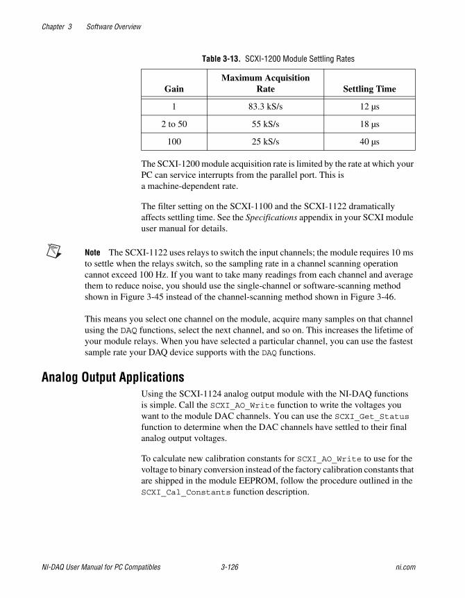
Chapter 3 Software Overview
NI-DAQ User Manual for PC Compatibles 3-126 ni.com
The SCXI-1200 module acquisition rate is limited by the rate at which yourPC can service interrupts from the parallel port. This isa machine-dependent rate.
The filter setting on the SCXI-1100 and the SCXI-1122 dramaticallyaffects settling time. See the Specifications appendix in your SCXI moduleuser manual for details.
Note The SCXI-1122 uses relays to switch the input channels; the module requires 10 msto settle when the relays switch, so the sampling rate in a channel scanning operationcannot exceed 100 Hz. If you want to take many readings from each channel and averagethem to reduce noise, you should use the single-channel or software-scanning methodshown in Figure 3-45 instead of the channel-scanning method shown in Figure 3-46.
This means you select one channel on the module, acquire many samples on that channelusing the DAQ functions, select the next channel, and so on. This increases the lifetime ofyour module relays. When you have selected a particular channel, you can use the fastestsample rate your DAQ device supports with the DAQ functions.
Analog Output ApplicationsUsing the SCXI-1124 analog output module with the NI-DAQ functionsis simple. Call the SCXI_AO_Write function to write the voltages youwant to the module DAC channels. You can use the SCXI_Get_Statusfunction to determine when the DAC channels have settled to their finalanalog output voltages.
To calculate new calibration constants for SCXI_AO_Write to use for thevoltage to binary conversion instead of the factory calibration constants thatare shipped in the module EEPROM, follow the procedure outlined in theSCXI_Cal_Constants function description.
Table 3-13. SCXI-1200 Module Settling Rates
GainMaximum Acquisition
Rate Settling Time
1 83.3 kS/s 12 µs
2 to 50 55 kS/s 18 µs
100 25 kS/s 40 µs
Chapter 3 Software Overview
© National Instruments Corporation 3-127 NI-DAQ User Manual for PC Compatibles
Digital ApplicationsIf you configured your digital or relay modules for multiplexed mode,use the SCXI_Set_State and SCXI_Get_State functions to accessyour digital or relay channels.
If you are using the SCXI-1160 module, you might want to use theSCXI_Get_Status function after calling the SCXI_Set_State function.SCXI_Get_Status tells you when the SCXI-1160 relays have finishedswitching.
If you are using the SCXI-1162/HV module, SCXI_Get_State readsthe module input channels. For the other digital and relay modules,SCXI_Get_State returns a software copy of the current state that NI-DAQmaintains. However, if you are using the SCXI-1163/R in parallel mode,SCXI_Get_State reads the hardware states.
If you are using the SCXI-1162/HV or SCXI-1163/R in parallel mode,you can use the SCXI functions as described above, or you can call theDIG_In_Prt and DIG_Out_Prt functions using the correct DAQ deviceport numbers that correspond to the SCXI module channels. The respectivechapters on the DIO-96, DIO-24, AT-MIO-16DE1-10, 6025E, andDIO-32F and 653Xs devices in the DAQ Hardware Overview Guide listthe onboard port numbers used for each device type if the SCXI-1162/HVor SCXI-1163/R is configured for parallel mode. The MIO and AI devices,Lab-PC+, and SCXI-1200 cannot use the SCXI-1162/HV or theSCXI-1163/R in parallel mode.
© National Instruments Corporation 4-1 NI-DAQ User Manual for PC Compatibles
4NI-DAQ Double Buffering
This chapter describes using double-buffered data acquisitions withNI-DAQ. This chapter applies to counter operations. However, you canread samples of any size.
OverviewConventional data acquisition software techniques, such as single-buffereddata acquisition, work well for most applications. However, moresophisticated applications involving larger amounts of data at higherrates require more advanced techniques for managing the data. One suchtechnique is double buffering. National Instruments uses double-bufferingtechniques in its driver software for continuous, uninterrupted input oroutput of large amounts of data.
This chapter discusses the fundamentals of double buffering, includingspecific information on how the NI-DAQ double-buffered functions work.
Note Input and output refer to both digital and analog operations in this chapter.
Single-Buffered Versus Double-Buffered DataThe most common method of data buffering found in conventional driversoftware is single buffering. In single-buffered input operations, a fixednumber of samples are acquired at a specified rate and transferred intocomputer memory. After the memory buffer stores the data, the computercan analyze, display, or store the data to the hard disk for later processing.Single-buffered output operations output a fixed number of samples fromcomputer memory at a specified rate. After outputting data, the buffercan be updated with new or freed data.
Single-buffered operations are relatively simple to implement, can usuallytake advantage of the full hardware speed of the DAQ device, and are veryuseful for many applications. The major disadvantage of single-bufferedoperations is that the amount of data that can be input or output is limitedto the amount of free memory available in the computer.
Chapter 4 NI-DAQ Double Buffering
NI-DAQ User Manual for PC Compatibles 4-2 ni.com
In double-buffered input operations, the data buffer is configured as acircular buffer. For input operations, the DAQ device fills the circularbuffer with data. When the end of the buffer is reached, the device returnsto the beginning of the buffer and fills it with data again. This processcontinues indefinitely until it is interrupted by a hardware error or clearedby a function call.
Double-buffered output operations also use a circular buffer. In this case,however, the DAQ device retrieves data from the circular buffer for output.When the end of the buffer is reached, the device begins retrieving datafrom the beginning of the buffer again.
Unlike single-buffered operations, double-buffered operations reusethe same buffer and are therefore able to input or output an infinite numberof data points without requiring an infinite amount of memory. However,for double buffering to be useful, there must be a means by which to accessthe data for updating, storing, and processing. The next two sectionsexplain how to access the data for double-buffered input and outputoperations.
Double-Buffered Input OperationsThe data buffer for double-buffered input operations is configured asa circular buffer. In addition, NI-DAQ logically divides the buffer into twoequal halves (no actual division exists in the buffer). By dividing the bufferinto two halves, NI-DAQ can coordinate user access to the data buffer withthe DAQ device. The coordination scheme is simple—NI-DAQ copies datafrom the circular buffer in sequential halves to a transfer buffer you create.You can process or store the data in the transfer buffer however you choose.
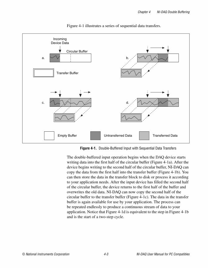
Chapter 4 NI-DAQ Double Buffering
© National Instruments Corporation 4-3 NI-DAQ User Manual for PC Compatibles
Figure 4-1 illustrates a series of sequential data transfers.
Figure 4-1. Double-Buffered Input with Sequential Data Transfers
The double-buffered input operation begins when the DAQ device startswriting data into the first half of the circular buffer (Figure 4-1a). After thedevice begins writing to the second half of the circular buffer, NI-DAQ cancopy the data from the first half into the transfer buffer (Figure 4-1b). Youcan then store the data in the transfer block to disk or process it accordingto your application needs. After the input device has filled the second halfof the circular buffer, the device returns to the first half of the buffer andoverwrites the old data. NI-DAQ can now copy the second half of thecircular buffer to the transfer buffer (Figure 4-1c). The data in the transferbuffer is again available for use by your application. The process canbe repeated endlessly to produce a continuous stream of data to yourapplication. Notice that Figure 4-1d is equivalent to the step in Figure 4-1band is the start of a two-step cycle.
IncomingDevice Data
Circular Buffer
Transfer Buffer
Empty Buffer Untransferred Data Transferred Data
a. b.
c. d.
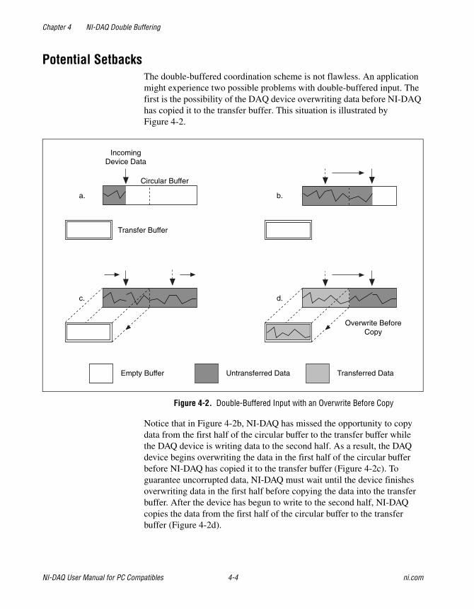
Chapter 4 NI-DAQ Double Buffering
NI-DAQ User Manual for PC Compatibles 4-4 ni.com
Potential SetbacksThe double-buffered coordination scheme is not flawless. An applicationmight experience two possible problems with double-buffered input. Thefirst is the possibility of the DAQ device overwriting data before NI-DAQhas copied it to the transfer buffer. This situation is illustrated byFigure 4-2.
Figure 4-2. Double-Buffered Input with an Overwrite Before Copy
Notice that in Figure 4-2b, NI-DAQ has missed the opportunity to copydata from the first half of the circular buffer to the transfer buffer whilethe DAQ device is writing data to the second half. As a result, the DAQdevice begins overwriting the data in the first half of the circular bufferbefore NI-DAQ has copied it to the transfer buffer (Figure 4-2c). Toguarantee uncorrupted data, NI-DAQ must wait until the device finishesoverwriting data in the first half before copying the data into the transferbuffer. After the device has begun to write to the second half, NI-DAQcopies the data from the first half of the circular buffer to the transferbuffer (Figure 4-2d).
IncomingDevice Data
Overwrite BeforeCopy
Circular Buffer
Transfer Buffer
Empty Buffer Untransferred Data Transferred Data
a. b.
c. d.
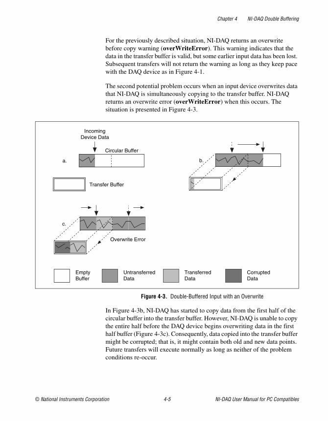
Chapter 4 NI-DAQ Double Buffering
© National Instruments Corporation 4-5 NI-DAQ User Manual for PC Compatibles
For the previously described situation, NI-DAQ returns an overwritebefore copy warning (overWriteError). This warning indicates that thedata in the transfer buffer is valid, but some earlier input data has been lost.Subsequent transfers will not return the warning as long as they keep pacewith the DAQ device as in Figure 4-1.
The second potential problem occurs when an input device overwrites datathat NI-DAQ is simultaneously copying to the transfer buffer. NI-DAQreturns an overwrite error (overWriteError) when this occurs. Thesituation is presented in Figure 4-3.
Figure 4-3. Double-Buffered Input with an Overwrite
In Figure 4-3b, NI-DAQ has started to copy data from the first half of thecircular buffer into the transfer buffer. However, NI-DAQ is unable to copythe entire half before the DAQ device begins overwriting data in the firsthalf buffer (Figure 4-3c). Consequently, data copied into the transfer buffermight be corrupted; that is, it might contain both old and new data points.Future transfers will execute normally as long as neither of the problemconditions re-occur.
IncomingDevice Data
Circular Buffer
Transfer Buffer
EmptyBuffer
UntransferredData
TransferredData
CorruptedData
a. b.
c.
Overwrite Error
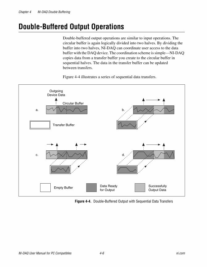
Chapter 4 NI-DAQ Double Buffering
NI-DAQ User Manual for PC Compatibles 4-6 ni.com
Double-Buffered Output OperationsDouble-buffered output operations are similar to input operations. Thecircular buffer is again logically divided into two halves. By dividing thebuffer into two halves, NI-DAQ can coordinate user access to the databuffer with the DAQ device. The coordination scheme is simple—NI-DAQcopies data from a transfer buffer you create to the circular buffer insequential halves. The data in the transfer buffer can be updatedbetween transfers.
Figure 4-4 illustrates a series of sequential data transfers.
Figure 4-4. Double-Buffered Output with Sequential Data Transfers
OutgoingDevice Data
Circular Buffer
Transfer Buffer
Empty Buffer Data Readyfor Output
SuccessfullyOutput Data
a.
c. d.
b.
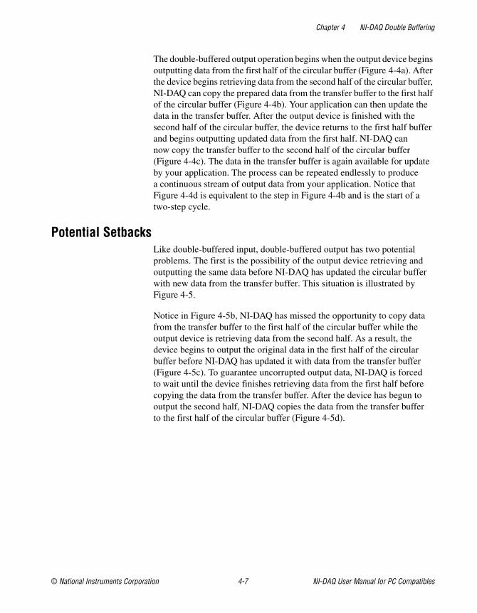
Chapter 4 NI-DAQ Double Buffering
© National Instruments Corporation 4-7 NI-DAQ User Manual for PC Compatibles
The double-buffered output operation begins when the output device beginsoutputting data from the first half of the circular buffer (Figure 4-4a). Afterthe device begins retrieving data from the second half of the circular buffer,NI-DAQ can copy the prepared data from the transfer buffer to the first halfof the circular buffer (Figure 4-4b). Your application can then update thedata in the transfer buffer. After the output device is finished with thesecond half of the circular buffer, the device returns to the first half bufferand begins outputting updated data from the first half. NI-DAQ cannow copy the transfer buffer to the second half of the circular buffer(Figure 4-4c). The data in the transfer buffer is again available for updateby your application. The process can be repeated endlessly to producea continuous stream of output data from your application. Notice thatFigure 4-4d is equivalent to the step in Figure 4-4b and is the start of atwo-step cycle.
Potential SetbacksLike double-buffered input, double-buffered output has two potentialproblems. The first is the possibility of the output device retrieving andoutputting the same data before NI-DAQ has updated the circular bufferwith new data from the transfer buffer. This situation is illustrated byFigure 4-5.
Notice in Figure 4-5b, NI-DAQ has missed the opportunity to copy datafrom the transfer buffer to the first half of the circular buffer while theoutput device is retrieving data from the second half. As a result, thedevice begins to output the original data in the first half of the circularbuffer before NI-DAQ has updated it with data from the transfer buffer(Figure 4-5c). To guarantee uncorrupted output data, NI-DAQ is forcedto wait until the device finishes retrieving data from the first half beforecopying the data from the transfer buffer. After the device has begun tooutput the second half, NI-DAQ copies the data from the transfer bufferto the first half of the circular buffer (Figure 4-5d).
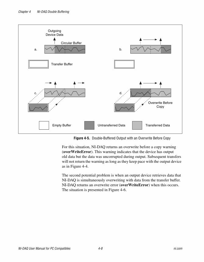
Chapter 4 NI-DAQ Double Buffering
NI-DAQ User Manual for PC Compatibles 4-8 ni.com
Figure 4-5. Double-Buffered Output with an Overwrite Before Copy
For this situation, NI-DAQ returns an overwrite before a copy warning(overWriteError). This warning indicates that the device has outputold data but the data was uncorrupted during output. Subsequent transferswill not return the warning as long as they keep pace with the output deviceas in Figure 4-4.
The second potential problem is when an output device retrieves data thatNI-DAQ is simultaneously overwriting with data from the transfer buffer.NI-DAQ returns an overwrite error (overWriteError) when this occurs.The situation is presented in Figure 4-6.
OutgoingDevice Data
Circular Buffer
Transfer Buffer
Empty Buffer Untransferred Data Transferred Data
a.
c. d.
b.
Overwrite BeforeCopy
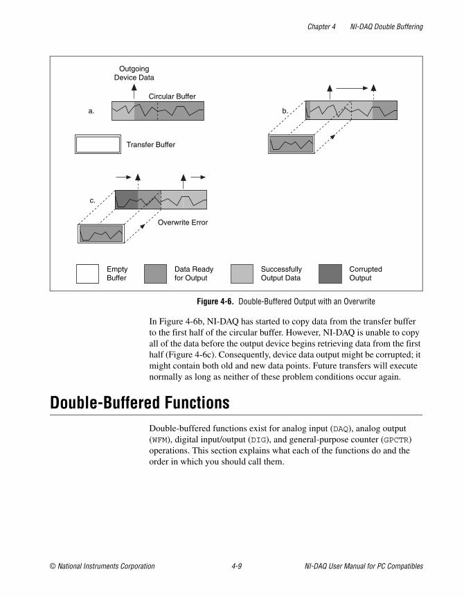
Chapter 4 NI-DAQ Double Buffering
© National Instruments Corporation 4-9 NI-DAQ User Manual for PC Compatibles
Figure 4-6. Double-Buffered Output with an Overwrite
In Figure 4-6b, NI-DAQ has started to copy data from the transfer bufferto the first half of the circular buffer. However, NI-DAQ is unable to copyall of the data before the output device begins retrieving data from the firsthalf (Figure 4-6c). Consequently, device data output might be corrupted; itmight contain both old and new data points. Future transfers will executenormally as long as neither of these problem conditions occur again.
Double-Buffered FunctionsDouble-buffered functions exist for analog input (DAQ), analog output(WFM), digital input/output (DIG), and general-purpose counter (GPCTR)operations. This section explains what each of the functions do and theorder in which you should call them.
OutgoingDevice Data
Circular Buffer
Transfer Buffer
EmptyBuffer
Data Readyfor Output
SuccessfullyOutput Data
CorruptedOutput
a. b.
c.
Overwrite Error
Chapter 4 NI-DAQ Double Buffering
NI-DAQ User Manual for PC Compatibles 4-10 ni.com
Double Buffer Configuration FunctionsThe Double Buffer Configuration functions enable and disable doublebuffering for input and output operations, and you can selectdouble-buffering options if any are available.
The configuration functions are as follows:
• DAQ_DB_Config
• WFM_DB_Config
• DIG_DB_Config
• GPCTR_Change_Parameter
For analog input operations, call DAQ_DB_Config prior to callingDAQ_Start, or a SCAN_Start to enable or disable double buffering.
For waveform operations, call WFM_DB_Config prior to calling WFM_Loadto enable or disable double buffering.
For digital block input and output operations, call DIG_DB_Config priorto calling DIG_Block_In, or DIG_Block_Out to enable or disable doublebuffering.
For counter operations, before calling GPCTR_Control to start yourcounter, call GPCTR_Change_Parameter to enable or disable continuousbuffering (with ND_Double). Counters transfer their data continuously,not in half buffers.
Double Buffer Transfer FunctionsAfter a double-buffered operation begins, the Double Buffer Transferfunctions transfer data to or from a circular buffer. The direction of thetransfer depends on the direction of the double-buffered operations. Alongwith copying data, the Double Buffer Transfer functions also check forpossible errors during the transfer.
For input operations, DB_Transfer copies data from alternating halvesof the circular input buffer to the transfer buffer. For output operations,DB_Transfer copies data from the buffer passed to the function toalternating halves of the circular output buffer. The function mightreturn an overwrite before a copy warning or an overwrite error(overWriteError) if a problem occurs during the transfer.
Note Waveform transfer functions do not detect overwrite before copy or overwrite errors.
Chapter 4 NI-DAQ Double Buffering
© National Instruments Corporation 4-11 NI-DAQ User Manual for PC Compatibles
The DB_Transfer functions for DAQ, WFM, DIG, and GPCTR aresynchronous for both input and output operations. In other words, whenyour application calls these functions, NI-DAQ does not return control toyour application until the transfer is complete. As a result, your applicationmight crash if NI-DAQ cannot complete the transfer. To avoid this situation,call the Timeout_Config function for DAQ, WFM, DIG, and GPCTR prior tostarting a double-buffered operation. The timeout configuration functionsets the maximum time allocated to complete a synchronous function callfor a device. For counter operations, the transfer function takes timeout asone of the parameters, so you do need to call Timeout_Config prior tocalling the transfer function.
The transfer functions are as follows:
• DAQ_DB_Transfer
• WFM_DB_Transfer
• DIG_DB_Transfer
• GPCTR_Read_Buffer
For analog input operations, call DAQ_DB_Transfer after starting adouble-buffered analog acquisition to perform a double-buffered transfer.
For waveform operations, call WFM_DB_Transfer after starting adouble-buffered waveform generation to perform a double-bufferedtransfer.
For digital block input and output operations, call DIG_DB_Transfer afterstarting a double-buffered digital operation to perform a double-bufferedtransfer.
For counter operations call GPCTR_Read_Buffer after starting theoperation to transfer a specified portion of the double buffer.
Double Buffer HalfReady FunctionsWith the Double Buffer HalfReady functions, applications can avoid thedelay possible when calling the double buffer transfer function. When youcall either of the transfer functions, NI-DAQ waits until the transfer to orfrom the circular buffer can be made; that is, the DAQ device is operatingon the opposite half of the circular buffer.
The Double Buffer HalfReady functions check if a double buffer transfercan be completed immediately. If the call to Double Buffer HalfReadyindicates a transfer cannot be made, your application can do other workand try again later.
Chapter 4 NI-DAQ Double Buffering
NI-DAQ User Manual for PC Compatibles 4-12 ni.com
The HalfReady functions are as follows:
• DAQ_DB_HalfReady
• WFM_DB_HalfReady
• DIG_DB_HalfReady
• GPCTR_Read_Buffer
For analog input operations, call DAQ_DB_HalfReady, afterstarting a double-buffered analog acquisition but prior to callingDAQ_DB_Transfer, to check the transfer status of the operation.
For analog output problems, call WFM_DB_HalfReady, afterstarting a double-buffered waveform generation but prior to callingWFM_DB_Transfer, to check the transfer status of the operation.
For digital block input and output operations, call DIG_DB_HalfReady,after starting a double-buffered digital operation but prior to callingDIG_DB_Transfer, to check the transfer status of the operation.
For counter operations, call GPCTR_Read_Buffer after callingGPCTR_Control with a timeOut of 0, to check the transfer status of theoperation. Counters actually transfer their data in a continuous manner,not a double-buffered manner.
ConclusionDouble buffering is a data acquisition software technique for continuouslyinputting or outputting large amounts of data with limited available systemmemory. However, double buffering might not be practical for high-speedinput or output applications. The throughput of a double-bufferedoperation is typically limited by the ability of the CPU to process the datawithin a given period of time. Specifically, data must be processed by theapplication at least as fast as the rate at which the device is writing orreading data. For many applications, this requirement depends on thespeed and efficiency of the computer system and programming language.
© National Instruments Corporation 5-1 NI-DAQ User Manual for PC Compatibles
5Transducer ConversionFunctions
This chapter describes the NI-DAQ Transducer Conversion functions.NI-DAQ includes source code for these functions.
The Transducer Conversion functions convert analog input voltages readfrom thermocouples, RTDs, thermistors, and strain gauges intotemperature or strain units:
RTD_Convert Supplied single-voltage andvoltage-buffer routines convert voltagesread from an RTD into resistance andthen into temperature in units for Celsius,Fahrenheit, Kelvin, or Rankine.
Strain_Convert Supplied single-voltage andvoltage-buffer routines convert voltagesread from a strain gauge into measuredstrain using the appropriate formula forthe strain gauge bridge configurationused.
Thermistor_Convert Supplied single-voltage andvoltage-buffer routines convert voltagesread from thermistors into temperature.
Thermocouple_Convert Supplied single-voltage andvoltage-buffer routines convert voltagesread from B-, E-, J-, K-, N-, R-, S-, orT-type thermocouples into temperature inCelsius, Fahrenheit, Kelvin, or Rankine.
NI-DAQ installs the source files for these functions in the same directoriesas the example programs. You can cut and paste, include, or merge theseconversion routines into your application source files in order to call theroutines in your application.
Chapter 5 Transducer Conversion Functions
NI-DAQ User Manual for PC Compatibles 5-2 ni.com
The conversion routines are included in NI-DAQ as source files rather thandriver function calls so that you have complete access to the conversionformulas. You can edit the conversion formulas or replace them with yourown to meet your application’s specific accuracy requirements. Commentsin the conversion source code simplify the process of making onlynecessary changes.
A header file for each language (convert.h for C/C++, convert.basfor Visual Basic) contains the constant definitions used in the conversionroutines. Include or merge this header file into your application program.
The transducer conversion routine descriptions apply to all languages.
Function Descriptions
RTD_Convert and RTD_Buf_ConvertThese functions convert a voltage or voltage buffer that NI-DAQ readsfrom an RTD into temperature.
Parameter DiscussionThe convType integer indicates whether to use the given conversionformula, or to use a user-defined formula that you have put into the routine.
0: The given conversion formula.
–1: Use a user-defined formula that has been added to the routine.
Iex is the excitation current in amps that was used with the RTD. If a 0 ispassed in Iex, a default excitation current of 150 × 10-6A (150 mA) isassumed.
Ro is the RTD resistance in ohms at 0 °C.
A and B are the coefficients of the Callendar Van-Düsen equation that fityour RTD.
The TempScale integer indicates which temperature units you want yourreturn values to be. Constant definitions for each temperature scale aregiven in the conversion header file.
1: Celsius
2: Fahrenheit
3: Kelvin
4: Rankine
Chapter 5 Transducer Conversion Functions
© National Instruments Corporation 5-3 NI-DAQ User Manual for PC Compatibles
The RTD_Convert routine has two remaining parameters—RTDVolts isthe voltage that NI-DAQ read from the RTD, and RTDTemp is the returntemperature value.
The RTD_Buf_Convert routine has three remaining parameters—numPtsis the number of voltage points to convert, RTDVoltBuf is the array thatcontains the voltages that NI-DAQ read from the RTD, and RTDTempBufis the return array that contains the temperatures.
Using This FunctionThe conversion routines first find the RTD resistance by dividingRTDVolts (or each element of RTDVoltBuf) by Iex. The functionconverts that resistance to a temperature using a solution to the CallendarVan-Düsen equation for RTDs:
Rt = R0[1 + At + Bt2 + C(t–100)t3]
For temperatures above 0 °C, the C coefficient is 0 and the equation reducesto a quadratic equation for which we have found the appropriate root. Thus,these conversion routines are accurate only for temperatures above 0 °C.
Your RTD documentation should give you R0 and the A and B coefficientsfor the Callendar Van-Düsen equation. The most common RTDs are 100 Ωplatinum RTDs that either follow the European temperature curve (alsoknown as the DIN 43760 standard) or the American curve. The values forA and B are as follows:
• European Curve (DIN 43760):
A = 3.90802 × 10⁻³
B = –5.80195 × 10⁻⁷
(α = 3.85 × 10⁻³; ∂ = 1.492)
• American Curve:
A = 3.9784 × 10⁻³
B = –5.8408 × 10⁻⁷
(α = 3.92 × 10⁻³; ∂ = 1.492)
Chapter 5 Transducer Conversion Functions
NI-DAQ User Manual for PC Compatibles 5-4 ni.com
Some RTD documentation contains values for α and ∂, from which you cancalculate A and B using the following equations:
where α is the temperature coefficient at T = 0 °C.
C = –α ß/1,000,000
where ß is a characteristic of your RTD similar to the α and ∂ equationcoefficients.
Strain_Convert and Strain_Buf_ConvertThese functions convert a voltage or voltage buffer that NI-DAQ read froma strain gauge to units of strain.
Parameter DiscussionThe bridgeConfig integer indicates in what type of bridge configurationthe strain gauge is mounted. Figure 5-1 shows all the different bridgeconfigurations and the corresponding values that you should pass inbridgeConfig.
Vex is the excitation voltage (in volts) that you used. If the value of Vexis 0, a default excitation voltage of 3.333 V is assumed. The SCXI-1121module provides excitation voltages of 10 V and 3.333 V. The SCXI-1122module provides an excitation voltage of 3.333 V.
GF is the gauge factor of the strain gauge.
v is Poisson’s Ratio (needed only in certain bridge configurations).
Rg is the strain gauge nominal value in ohms.
RL is the lead resistance in ohms. In many cases, the lead resistance isnegligible and you can pass a value of 0 for RL to the routine. Otherwise,you can measure RL to be more accurate.
Vinit is the unstrained voltage of the strain gauge in volts after it is mountedin its bridge configuration. Read this voltage at the beginning of yourapplication and save it to pass to the strain gauge conversion routines.
A α 1 ∂ 100⁄+( )=
B α∂ 10 000 1002, ,( )⁄–=
Chapter 5 Transducer Conversion Functions
© National Instruments Corporation 5-5 NI-DAQ User Manual for PC Compatibles
The Strain_Convert routine has two remaining parameters—strainVolts is the voltage that NI-DAQ read from the strain gauge,and strainVal is the return strain value.
The Strain_Buf_Convert routine has three remainingparameters—numPts is the number of voltage points to convert,strainVoltBuf is the array that contains the voltages that NI-DAQ readfrom the strain gauge, and strainValBuf is the return array that containsthe strain values.
Using This FunctionThe conversion formula used is based solely on the bridge configuration.Figure 5-1 shows the seven bridge configurations supported and thecorresponding formulas. For all bridge configurations, NI-DAQ usesthe following formula to obtain Vr:
Vr = (strainVolts – Vinit) / Vex
In the circuit diagrams shown in Figure 5-1, Vout is the voltage you measureand pass to the Strain_Convert function as the strainVolts parameter.In the quarter-bridge and half-bridge configurations, R1 and R2 are dummyresistors that are not directly incorporated into the conversion formula.The SCXI-1121 and SCXI-1122 modules provide R1 and R2 for abridge-completion network, if needed. Refer to your Getting Startedwith SCXI manual for more information on bridge-completion networksand voltage excitation.
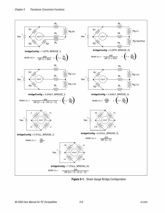
Chapter 5 Transducer Conversion Functions
NI-DAQ User Manual for PC Compatibles 5-6 ni.com
Figure 5-1. Strain Gauge Bridge Configuration
bridgeConfig = 7 (FULL_BRIDGE_III)
strain (ε) = -2VrGF [(v + 1) - Vr (v - 1)]
bridgeConfig = 3 (HALF_BRIDGE_I)
-4VrGF [(1 + v) - 2Vr (v - 1)]
strain (ε) = • ( )1 + RLRg
Vex VOUT- +
-
+Rg (+ε)
Rg (-vε)
RL
RL
R1
R2
RL
bridgeConfig = 4 (HALF_BRIDGE_II)
strain (ε) = -2VrGF • ( )1 + RL
Rg
Vex VOUT- +
-
+Rg (+ε)
Rg (-ε)
RL
RL
R1
R2
RL
bridgeConfig = 5 (FULL_BRIDGE_I)
strain (ε) = -VrGF
Vex
-ε
-ε
+ε
+ε
VOUT- +
-
+
Vex
-vε
-vε
+ε
+ε
VOUT- +
-
+
bridgeConfig = 6 (FULL_BRIDGE_II)
strain (ε) = -2VrGF (v + 1)
Vex
-vε
-ε
+ε
+vε
VOUT- +
-
+
RL
Vex VOUT- +
-
+
R1
R2 R3
Rg (e)
RL
RL
strain (ε) = • ( )1 + RLRg
-4VrGF (1 + 2Vr)
bridgeConfig = 1 (QTR_BRIDGE_I)
RL
Vex VOUT- +
-
+Rg (ε)
Rg (dummy)
RL
RL
R1
R2
strain (ε) = • ( )1 + RLRg
-4VrGF (1 + 2Vr)
bridgeConfig = 2 (QTR_BRIDGE_II)
Chapter 5 Transducer Conversion Functions
© National Instruments Corporation 5-7 NI-DAQ User Manual for PC Compatibles
Thermistor_Convert and Thermistor_Buf_ConvertThese functions convert a voltage or voltage buffer read from a thermistorinto temperature. Some SCXI terminal blocks have onboard thermistorsthat you can use to do cold-junction compensation.
Parameter DiscussionVref is the voltage reference you apply across the thermistor circuit(see Figure 5-2) in volts. The thermistor on the SCXI terminal blocks hasa Vref of 2.5 V.
R1 is the value of the resistor in series with your thermistor (see Figure 5-2)in ohms. The thermistor on the SCXI terminal blocks has an R1 value of5,000 Ω.
The TempScale integer indicates in which temperature unit you wantyour return values to be. Constant definitions for each temperature scaleare assigned in the conversion header file.
1: Celsius
2: Fahrenheit
3: Kelvin
4: Rankine
The Thermistor_Convert function has two remainingparameters—Volts is the voltage that you read from the thermistor,and Temperature is the return temperature value assigned in unitsdetermined by TempScale.
The Thermistor_Buf_Convert function has three remainingparameters—numPts is the number of voltage points to convert, VoltBufis the array of voltages that you read from the thermistor, and TempBuf isthe return array of temperature values assigned in units determined byTempScale.
Chapter 5 Transducer Conversion Functions
NI-DAQ User Manual for PC Compatibles 5-8 ni.com
Using This FunctionThe following equation expresses the relationship between Volts and Rt,the thermistor resistance (see Figure 5-2).
Volts = Vref ( Rt / (R1 + Rt))
Solving the previous equation for Rt, we have:
Rt = R1 ( Volts / (Vref – Volts))
After this function calculates Rt, the function uses the following equationto convert Rt, the thermistor resistance, to temperature in Kelvin. Thefunction then converts the temperature to the temperature scale you want,if necessary.
T = 1 / ( a + b(ln Rt) + c(ln Rt)^3)
The values used for a, b, and c are given below. If you are using a thermistorwith different values for a, b, and c (consult your thermistor data sheet),you can edit the thermistor conversion routine to use your own a, b, andc values.
a = 1.295361E–3
The following equation expresses the relationship between Volts and Rt,the thermistor resistance (see Figure 5-2).
Volts = Vref ( Rt / (R1 + Rt))
Solving the previous equation for Rt, you have:
Rt = R1 ( Volts / (Vref – Volts))
When you calculate Rt, you use the following equation to convert Rt,the thermistor resistance, to temperature in Kelvin. Then convert thetemperature to the temperature scale you want, if necessary.
T = 1 / ( a + b(ln Rt) + c(ln Rt)^3)
The values used for a, b, and c are shown below. These values are correctfor the thermistors provided on the SCXI terminal blocks. If you are usinga thermistor with different values for a, b, and c (consult you thermistor
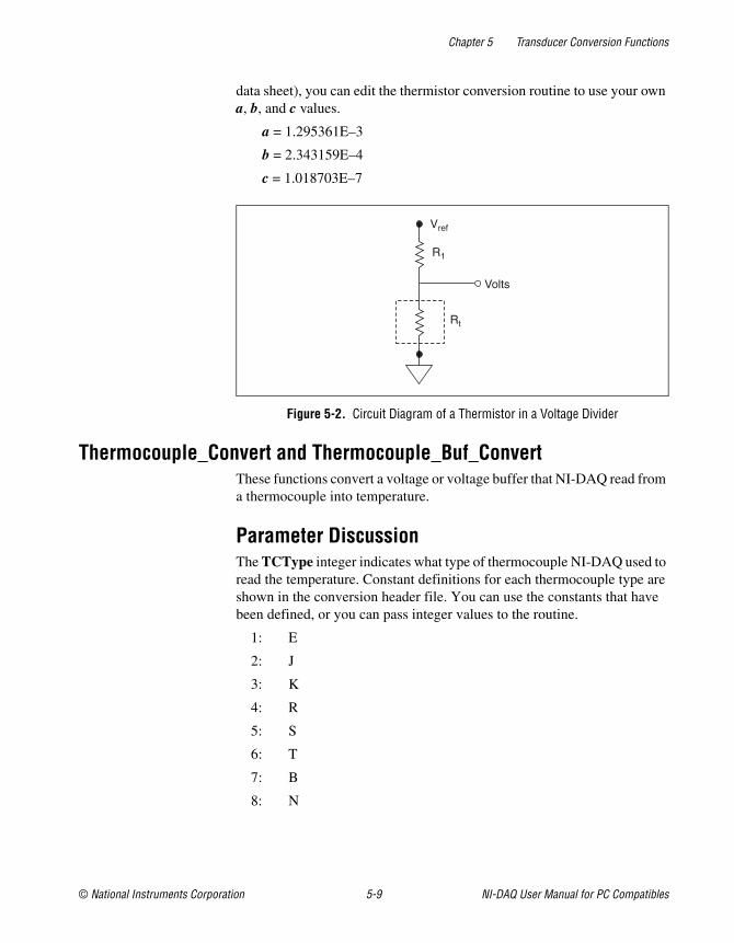
Chapter 5 Transducer Conversion Functions
© National Instruments Corporation 5-9 NI-DAQ User Manual for PC Compatibles
data sheet), you can edit the thermistor conversion routine to use your owna, b, and c values.
a = 1.295361E–3
b = 2.343159E–4
c = 1.018703E–7
Figure 5-2. Circuit Diagram of a Thermistor in a Voltage Divider
Thermocouple_Convert and Thermocouple_Buf_ConvertThese functions convert a voltage or voltage buffer that NI-DAQ read froma thermocouple into temperature.
Parameter DiscussionThe TCType integer indicates what type of thermocouple NI-DAQ used toread the temperature. Constant definitions for each thermocouple type areshown in the conversion header file. You can use the constants that havebeen defined, or you can pass integer values to the routine.
1: E
2: J
3: K
4: R
5: S
6: T
7: B
8: N
Rt
R1
Vref
Volts
Chapter 5 Transducer Conversion Functions
NI-DAQ User Manual for PC Compatibles 5-10 ni.com
CJCTemp is the temperature in Celsius that NI-DAQ uses forcold-junction compensation of the thermocouple temperature. If you areusing SCXI, most likely this is the temperature that NI-DAQ read from thetemperature sensor on the SCXI terminal block. The AMUX-64T also hasa temperature sensor that you can use for this purpose.
The TempScale integer indicates in which temperature unit you want yourreturn values to be. Constant definitions for each temperature scale areshown in the conversion header file.
1: Celsius
2: Fahrenheit
3: Kelvin
4: Rankine
The Thermocouple_Convert routine has two remainingparameters—TCVolts is the voltage that NI-DAQ read from thethermocouple, and TCTemp is the return temperature value.
The Thermocouple_Buf_Convert routine has three remainingparameters—numPts is the number of voltage points to convert,TCVoltBuf is the array that contains the voltages that NI-DAQ readfrom the thermocouple, and TCTempBuf is the return array that containsthe temperatures.
Using This FunctionThese routines convert TCVolts (or each element of TCVoltBuf) into acorresponding temperature after performing the necessary cold-junctioncompensation. Cold-junction compensation is done by convertingCJCTemp into an equivalent thermocouple voltage and adding it toTCVolts. The actual temperature-to-voltage conversion is done bychoosing the appropriate reference equation that characterizes the correcttemperature subrange for the specific TCType. The valid temperaturerange for a given TCType is divided into several subranges with eachsubrange characterized by a reference equation. The computed voltageis then added to TCVolts to perform the cold-junction correction. Theconversion of TCVolts into a corresponding temperature is done by usinginverse equations that are specified for a given TCType for differentsubranges. These inverse equations have an error tolerance as shown inTable 5-1. All the reference equations and inverse equations used inthese routines are from NIST Monograph 175.
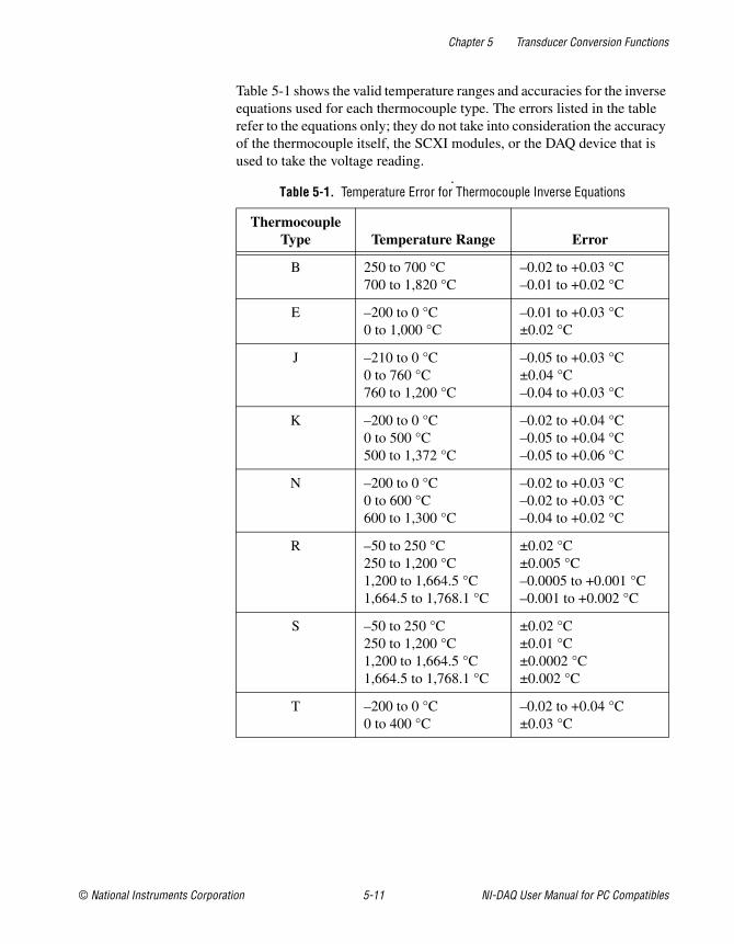
Chapter 5 Transducer Conversion Functions
© National Instruments Corporation 5-11 NI-DAQ User Manual for PC Compatibles
Table 5-1 shows the valid temperature ranges and accuracies for the inverseequations used for each thermocouple type. The errors listed in the tablerefer to the equations only; they do not take into consideration the accuracyof the thermocouple itself, the SCXI modules, or the DAQ device that isused to take the voltage reading.
.Table 5-1. Temperature Error for Thermocouple Inverse Equations
ThermocoupleType Temperature Range Error
B 250 to 700 °C700 to 1,820 °C
–0.02 to +0.03 °C–0.01 to +0.02 °C
E –200 to 0 °C0 to 1,000 °C
–0.01 to +0.03 °C±0.02 °C
J –210 to 0 °C0 to 760 °C760 to 1,200 °C
–0.05 to +0.03 °C±0.04 °C–0.04 to +0.03 °C
K –200 to 0 °C0 to 500 °C500 to 1,372 °C
–0.02 to +0.04 °C–0.05 to +0.04 °C–0.05 to +0.06 °C
N –200 to 0 °C0 to 600 °C600 to 1,300 °C
–0.02 to +0.03 °C–0.02 to +0.03 °C–0.04 to +0.02 °C
R –50 to 250 °C250 to 1,200 °C1,200 to 1,664.5 °C1,664.5 to 1,768.1 °C
±0.02 °C±0.005 °C–0.0005 to +0.001 °C–0.001 to +0.002 °C
S –50 to 250 °C250 to 1,200 °C1,200 to 1,664.5 °C1,664.5 to 1,768.1 °C
±0.02 °C±0.01 °C±0.0002 °C±0.002 °C
T –200 to 0 °C0 to 400 °C
–0.02 to +0.04 °C±0.03 °C
© National Instruments Corporation A-1 NI-DAQ User Manual for PC Compatibles
ATechnical Support Resources
Web SupportNational Instruments Web support is your first stop for help in solvinginstallation, configuration, and application problems and questions. Onlineproblem-solving and diagnostic resources include frequently askedquestions, knowledge bases, product-specific troubleshooting wizards,manuals, drivers, software updates, and more. Web support is availablethrough the Technical Support section of ni.com
NI Developer ZoneThe NI Developer Zone at zone.ni.com is the essential resource forbuilding measurement and automation systems. At the NI Developer Zone,you can easily access the latest example programs, system configurators,tutorials, technical news, as well as a community of developers ready toshare their own techniques.
Customer EducationNational Instruments provides a number of alternatives to satisfy yourtraining needs, from self-paced tutorials, videos, and interactive CDs toinstructor-led hands-on courses at locations around the world. Visit theCustomer Education section of ni.com for online course schedules,syllabi, training centers, and class registration.
System IntegrationIf you have time constraints, limited in-house technical resources, or otherdilemmas, you may prefer to employ consulting or system integrationservices. You can rely on the expertise available through our worldwidenetwork of Alliance Program members. To find out more about ourAlliance system integration solutions, visit the System Integration sectionof ni.com
Appendix A Technical Support Resources
NI-DAQ User Manual for PC Compatibles A-2 ni.com
Worldwide SupportNational Instruments has offices located around the world to help addressyour support needs. You can access our branch office Web sites from theWorldwide Offices section of ni.com. Branch office web sites provideup-to-date contact information, support phone numbers, e-mail addresses,and current events.
If you have searched the technical support resources on our Web site andstill cannot find the answers you need, contact your local office or NationalInstruments corporate. Phone numbers for our worldwide offices are listedat the front of this manual.
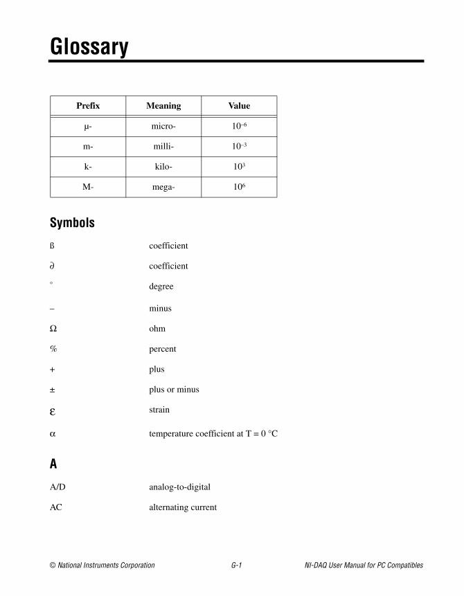
© National Instruments Corporation G-1 NI-DAQ User Manual for PC Compatibles
Glossary
Prefix Meaning Value
µ- micro- 10–6
m- milli- 10–3
k- kilo- 103
M- mega- 106
Symbols
ß coefficient
∂ coefficient
° degree
– minus
Ω ohm
% percent
+ plus
± plus or minus
ε strain
α temperature coefficient at T = 0 °C
A
A/D analog-to-digital
AC alternating current
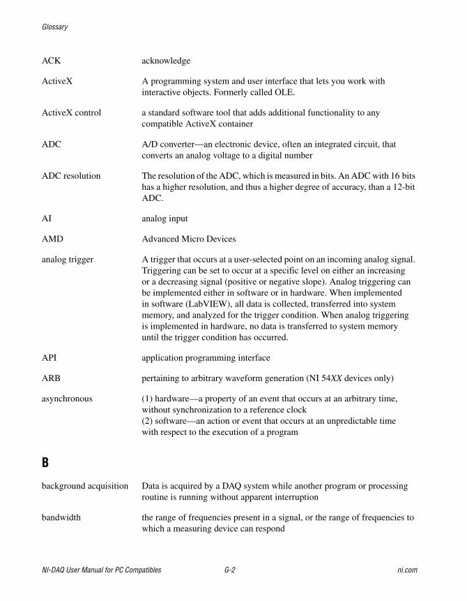
Glossary
NI-DAQ User Manual for PC Compatibles G-2 ni.com
ACK acknowledge
ActiveX A programming system and user interface that lets you work withinteractive objects. Formerly called OLE.
ActiveX control a standard software tool that adds additional functionality to anycompatible ActiveX container
ADC A/D converter—an electronic device, often an integrated circuit, thatconverts an analog voltage to a digital number
ADC resolution The resolution of the ADC, which is measured in bits. An ADC with 16 bitshas a higher resolution, and thus a higher degree of accuracy, than a 12-bitADC.
AI analog input
AMD Advanced Micro Devices
analog trigger A trigger that occurs at a user-selected point on an incoming analog signal.Triggering can be set to occur at a specific level on either an increasingor a decreasing signal (positive or negative slope). Analog triggering canbe implemented either in software or in hardware. When implementedin software (LabVIEW), all data is collected, transferred into systemmemory, and analyzed for the trigger condition. When analog triggeringis implemented in hardware, no data is transferred to system memoryuntil the trigger condition has occurred.
API application programming interface
ARB pertaining to arbitrary waveform generation (NI 54XX devices only)
asynchronous (1) hardware—a property of an event that occurs at an arbitrary time,without synchronization to a reference clock(2) software—an action or event that occurs at an unpredictable timewith respect to the execution of a program
B
background acquisition Data is acquired by a DAQ system while another program or processingroutine is running without apparent interruption
bandwidth the range of frequencies present in a signal, or the range of frequencies towhich a measuring device can respond
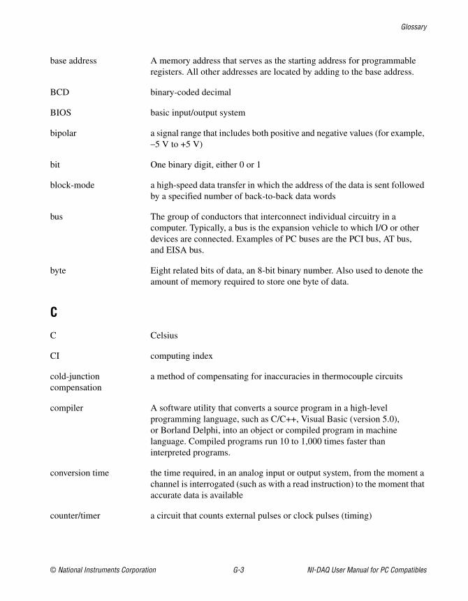
Glossary
© National Instruments Corporation G-3 NI-DAQ User Manual for PC Compatibles
base address A memory address that serves as the starting address for programmableregisters. All other addresses are located by adding to the base address.
BCD binary-coded decimal
BIOS basic input/output system
bipolar a signal range that includes both positive and negative values (for example,–5 V to +5 V)
bit One binary digit, either 0 or 1
block-mode a high-speed data transfer in which the address of the data is sent followedby a specified number of back-to-back data words
bus The group of conductors that interconnect individual circuitry in acomputer. Typically, a bus is the expansion vehicle to which I/O or otherdevices are connected. Examples of PC buses are the PCI bus, AT bus,and EISA bus.
byte Eight related bits of data, an 8-bit binary number. Also used to denote theamount of memory required to store one byte of data.
C
C Celsius
CI computing index
cold-junctioncompensation
a method of compensating for inaccuracies in thermocouple circuits
compiler A software utility that converts a source program in a high-levelprogramming language, such as C/C++, Visual Basic (version 5.0),or Borland Delphi, into an object or compiled program in machinelanguage. Compiled programs run 10 to 1,000 times faster thaninterpreted programs.
conversion time the time required, in an analog input or output system, from the moment achannel is interrogated (such as with a read instruction) to the moment thataccurate data is available
counter/timer a circuit that counts external pulses or clock pulses (timing)
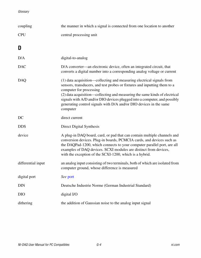
Glossary
NI-DAQ User Manual for PC Compatibles G-4 ni.com
coupling the manner in which a signal is connected from one location to another
CPU central processing unit
D
D/A digital-to-analog
DAC D/A converter—an electronic device, often an integrated circuit, thatconverts a digital number into a corresponding analog voltage or current
DAQ (1) data acquisition—collecting and measuring electrical signals fromsensors, transducers, and test probes or fixtures and inputting them to acomputer for processing(2) data acquisition—collecting and measuring the same kinds of electricalsignals with A/D and/or DIO devices plugged into a computer, and possiblygenerating control signals with D/A and/or DIO devices in the samecomputer
DC direct current
DDS Direct Digital Synthesis
device A plug-in DAQ board, card, or pad that can contain multiple channels andconversion devices. Plug-in boards, PCMCIA cards, and devices such asthe DAQPad-1200, which connects to your computer parallel port, are allexamples of DAQ devices. SCXI modules are distinct from devices,with the exception of the SCXI-1200, which is a hybrid.
differential input an analog input consisting of two terminals, both of which are isolated fromcomputer ground, whose difference is measured
digital port See port
DIN Deutsche Industrie Norme (German Industrial Standard)
DIO digital I/O
dithering the addition of Gaussian noise to the analog input signal
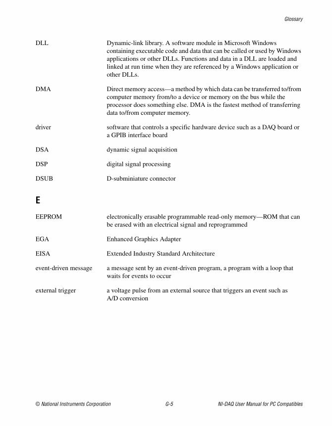
Glossary
© National Instruments Corporation G-5 NI-DAQ User Manual for PC Compatibles
DLL Dynamic-link library. A software module in Microsoft Windowscontaining executable code and data that can be called or used by Windowsapplications or other DLLs. Functions and data in a DLL are loaded andlinked at run time when they are referenced by a Windows application orother DLLs.
DMA Direct memory access—a method by which data can be transferred to/fromcomputer memory from/to a device or memory on the bus while theprocessor does something else. DMA is the fastest method of transferringdata to/from computer memory.
driver software that controls a specific hardware device such as a DAQ board ora GPIB interface board
DSA dynamic signal acquisition
DSP digital signal processing
DSUB D-subminiature connector
E
EEPROM electronically erasable programmable read-only memory—ROM that canbe erased with an electrical signal and reprogrammed
EGA Enhanced Graphics Adapter
EISA Extended Industry Standard Architecture
event-driven message a message sent by an event-driven program, a program with a loop thatwaits for events to occur
external trigger a voltage pulse from an external source that triggers an event such asA/D conversion
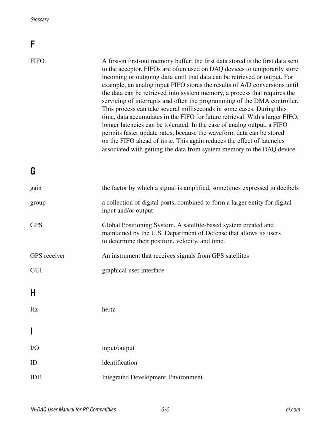
Glossary
NI-DAQ User Manual for PC Compatibles G-6 ni.com
F
FIFO A first-in first-out memory buffer; the first data stored is the first data sentto the acceptor. FIFOs are often used on DAQ devices to temporarily storeincoming or outgoing data until that data can be retrieved or output. Forexample, an analog input FIFO stores the results of A/D conversions untilthe data can be retrieved into system memory, a process that requires theservicing of interrupts and often the programming of the DMA controller.This process can take several milliseconds in some cases. During thistime, data accumulates in the FIFO for future retrieval. With a larger FIFO,longer latencies can be tolerated. In the case of analog output, a FIFOpermits faster update rates, because the waveform data can be storedon the FIFO ahead of time. This again reduces the effect of latenciesassociated with getting the data from system memory to the DAQ device.
G
gain the factor by which a signal is amplified, sometimes expressed in decibels
group a collection of digital ports, combined to form a larger entity for digitalinput and/or output
GPS Global Positioning System. A satellite-based system created andmaintained by the U.S. Department of Defense that allows its usersto determine their position, velocity, and time.
GPS receiver An instrument that receives signals from GPS satellites
GUI graphical user interface
H
Hz hertz
I
I/O input/output
ID identification
IDE Integrated Development Environment
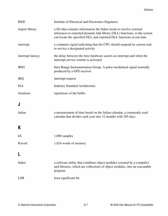
Glossary
© National Instruments Corporation G-7 NI-DAQ User Manual for PC Compatibles
IEEE Institute of Electrical and Electronics Engineers
import library a file that contains information the linker needs to resolve externalreferences to exported dynamic link library (DLL) functions, so the systemcan locate the specified DLL and exported DLL functions at run time
interrupt a computer signal indicating that the CPU should suspend its current taskto service a designated activity
interrupt latency the delay between the time hardware asserts an interrupt and when theinterrupt service routine is activated
IRIG Inter Range Instrumentation Group. A pulse-modulated signal normallyproduced by a GPS receiver.
IRQ interrupt request
ISA Industry Standard Architecture
iterations repetitions of the buffer
J
Julian a measurement of time based on the Julian calendar, a commonly usedcalendar that divides each year into 12 months with 365 days
K
kS 1,000 samples
Kword 1,024 words of memory
L
linker a software utility that combines object modules (created by a compiler)and libraries, which are collections of object modules, into an executableprogram
LSB least significant bit
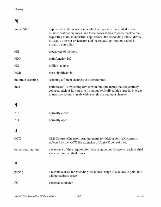
Glossary
NI-DAQ User Manual for PC Compatibles G-8 ni.com
M
master/slave Type of network connection in which a request is transmitted to oneor more destination nodes, and those nodes send a response back to therequesting node. In industrial applications, the responding (slave) deviceis usually a sensor or actuator, and the requesting (master) device isusually a controller.
MB megabytes of memory
MIO multifunction I/O
MS million samples
MSB most significant bit
multirate scanning scanning different channels at different rates
mux multiplexer—a switching device with multiple inputs that sequentiallyconnects each of its inputs to its output, typically at high speeds, in orderto measure several signals with a single analog input channel
N
NC normally closed
NO normally open
O
OCX OLE Control eXtension. Another name for OLE or ActiveX controls,reflected by the .OCX file extension of ActiveX control files.
output settling time the amount of time required for the analog output voltage to reach its finalvalue within specified limits
P
paging a technique used for extending the address range of a device to point intoa larger address space
PC personal computer
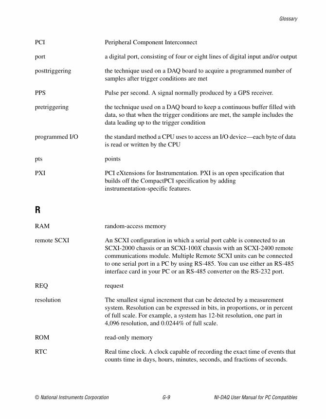
Glossary
© National Instruments Corporation G-9 NI-DAQ User Manual for PC Compatibles
PCI Peripheral Component Interconnect
port a digital port, consisting of four or eight lines of digital input and/or output
posttriggering the technique used on a DAQ board to acquire a programmed number ofsamples after trigger conditions are met
PPS Pulse per second. A signal normally produced by a GPS receiver.
pretriggering the technique used on a DAQ board to keep a continuous buffer filled withdata, so that when the trigger conditions are met, the sample includes thedata leading up to the trigger condition
programmed I/O the standard method a CPU uses to access an I/O device—each byte of datais read or written by the CPU
pts points
PXI PCI eXtensions for Instrumentation. PXI is an open specification thatbuilds off the CompactPCI specification by addinginstrumentation-specific features.
R
RAM random-access memory
remote SCXI An SCXI configuration in which a serial port cable is connected to anSCXI-2000 chassis or an SCXI-100X chassis with an SCXI-2400 remotecommunications module. Multiple Remote SCXI units can be connectedto one serial port in a PC by using RS-485. You can use either an RS-485interface card in your PC or an RS-485 converter on the RS-232 port.
REQ request
resolution The smallest signal increment that can be detected by a measurementsystem. Resolution can be expressed in bits, in proportions, or in percentof full scale. For example, a system has 12-bit resolution, one part in4,096 resolution, and 0.0244% of full scale.
ROM read-only memory
RTC Real time clock. A clock capable of recording the exact time of events thatcounts time in days, hours, minutes, seconds, and fractions of seconds.
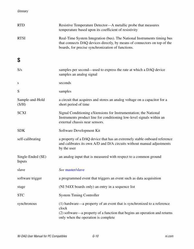
Glossary
NI-DAQ User Manual for PC Compatibles G-10 ni.com
RTD Resistive Temperature Detector—A metallic probe that measurestemperature based upon its coefficient of resistivity
RTSI Real-Time System Integration (bus). The National Instruments timing busthat connects DAQ devices directly, by means of connectors on top of theboards, for precise synchronization of functions.
S
S/s samples per second—used to express the rate at which a DAQ devicesamples an analog signal
s seconds
S samples
Sample-and-Hold(S/H)
a circuit that acquires and stores an analog voltage on a capacitor for ashort period of time
SCXI Signal Conditioning eXtensions for Instrumentation; the NationalInstruments product line for conditioning low-level signals within anexternal chassis near sensors.
SDK Software Development Kit
self-calibrating a property of a DAQ device that has an extremely stable onboard referenceand calibrates its own A/D and D/A circuits without manual adjustmentsby the user
Single-Ended (SE)Inputs
an analog input that is measured with respect to a common ground
slave See master/slave
software trigger a programmed event that triggers an event such as data acquisition
stage (NI 54XX boards only) an entry in a sequence list
STC System Timing Controller
synchronous (1) hardware—a property of an event that is synchronized to a referenceclock(2) software—a property of a function that begins an operation and returnsonly when the operation is complete
Glossary
© National Instruments Corporation G-11 NI-DAQ User Manual for PC Compatibles
T
TC terminal count
throughput rate the data, measured in bytes/s, for a given continuous operation, calculatedto include software overhead
transfer rate the rate, measured in bytes/s, at which data is moved from source todestination after software initialization and set up operations; the maximumrate at which the hardware can operate
TSR Terminate-and-Stay Resident
U
unipolar a signal range that is always positive (for example, 0 to +10 V)
USB universal serial bus
V
V volt
VDC volts direct current
VPICD Virtual Programmable Interrupt Controller Device
VXI VMEbus eXtensions for Instrumentation
© National Instruments Corporation I-1 NI-DAQ User Manual for PC Compatibles
Index
Numbers1200 series devices. See Lab and
1200 series devices.4451and 4551 devices
counter usage, 3-50FIFO lag effect, 3-51 to 3-52
6025E groups of ports, 3-556115 and 6120 devices. See PCI-6115 and
PCI-6120 devices.622XI devices
counter usage, 3-50FIFO lag effect, 3-51 to 3-52
652X devicesdigital change detection applications, 3-60digital change notification
applications, 3-60653X devices
digital change detectionapplications, 3-61 to 3-62
groups of ports, 3-55 to 3-56pattern generation, 3-74 to 3-75RTSI connections, 3-105 to 3-106
660X devices, RTSI connections, 3-103671X devices
counter usage, 3-50FIFO lag effect, 3-51 to 3-52RTSI connections, 3-103
AACK1 signal
653X RTSI connections (table), 3-105DIO-32F RTSI connections (table), 3-104
ACK2 signal653X RTSI connections (table), 3-105DIO-32F RTSI connections (table), 3-104
ActiveX controls for Visual Basic, 3-6 to 3-7
AI device terminology (table), xv-xviiAI_Change_Parameter function, 3-16AI_Check function, 3-16AI_Clear function, 3-16AI_Configure function, 3-16AI_Mux_Config function, 3-17AI_Read function, 3-17AI_Read_Scan function, 3-17AI_Read_VScan function, 3-17AI_Setup function, 3-17AI_VRead function, 3-17AI_VScale function, 3-17Align_DMA_Buffer function, 3-2Am9513-based devices
gating modes, 3-79timebases, 3-78
AMUX-64T external multiplexer support, 3-25Analog Alarm Event control, 3-11 to 3-13
properties (table), 3-11setting program flow, 3-12 to 3-13setting properties, 3-12
analog input application tips. See dataacquisition application tips.
analog input functions. See data acquisitionfunctions; one-shot analog input functions.
analog output application tips, 3-36 to 3-38equivalent analog output calls (figure), 3-36SCXI applications, 3-126simple application, 3-37software update application, 3-37 to 3-38
analog output devices, reference voltages for(tables), 3-49 to 3-50
analog output functions, 3-35 to 3-36. See alsowaveform generation functions.
AO_Change_Parameter, 3-35AO_Configure, 3-35AO_Update, 3-35
Index
NI-DAQ User Manual for PC Compatibles I-2 ni.com
AO_VScale, 3-36AO_VWrite, 3-36AO_Write, 3-36
Analog Trigger Event control, 3-9 to 3-11properties (table), 3-9 to 3-10setting properties, 3-10 to 3-11
AO_Calibrate function, 3-3AO_Change_Parameter function, 3-35AO_Configure function, 3-35AO_Update function, 3-35AO_VScale function, 3-36AO_VWrite function, 3-36AO_Write function, 3-36applications for Windows. See building
Windows applications.AT-AO-6/10
counter usage in waveformgeneration, 3-51
FIFO lag effect, 3-51 to 3-52reference voltages for waveform
generation (tables), 3-50RTSI bus connections, 3-104
AT-DIO-32F. See DIO-32F.AT-MIO-16DE-10, groups of ports, 3-55
BBorland C++ Windows
applications, 2-7 to 2-8Borland Delphi, 2-8buffer allocation in Windows applications
Microsoft Visual Basic, 2-5 to 2-6Microsoft Visual C++, 2-3
building Windows applications, 2-1 to 2-10Borland C++, 2-7 to 2-8Microsoft Visual Basic, 2-4 to 2-6Microsoft Visual C++, 2-2 to 2-3NI-DAQ examples, 2-9 to 2-10NI-DAQ libraries, 2-1
CCalibrate_1200 function, 3-3 to 3-4Calibrate_DSA function, 3-4Calibrate_E_Series function, 3-4Calibrate_TIO function, 3-4calibration functions. See software-calibration
and device-specific functions.clocks or time counters for NI-TIO
devices, 3-95 to 3-102accuracy, 3-98clock resolution, 3-95example clock in measurement
system, 3-98 to 3-99sample use cases, 3-99 to 3-102synchronization, 3-96 to 3-97
IRIG (Inter Range InstrumentationGroup) protocols, 3-97 to 3-98
pulse per second, 3-96 to 3-97real-time clock
synchronizing to GPS receiver(figure), 3-95
sample code for setting up clockusing PPS, 3-96 to 3-97
concatenated event counting, 3-88 to 3-89Config_Alarm_Deadband function, 3-5Config_ATrig_Event_Message function, 3-5Config_DAQ_Event_Message function, 3-5configuration
NI-DAQ hardware support(tables), 1-4 to 1-6
using Measurement & AutomationExplorer, 1-7
configuration functions. See also initializationand general-configuration functions.
AI_Change_Parameter, 3-16AI_Configure, 3-16AI_Mux_Config, 3-17AI_Setup, 3-17AO_Configure, 3-35Config_Alarm_Deadband, 3-5Config_ATrig_Event_Message, 3-5
Index
© National Instruments Corporation I-3 NI-DAQ User Manual for PC Compatibles
Config_DAQ_Event_Message, 3-5Configure_HW_Analog_Trigger, 3-4CTR_Config, 3-77CTR_FOUT_Config, 3-77DAQ_Config, 3-21DAQ_DB_Config, 3-23, 4-10DAQ_StopTrigger_Config, 3-22DIG_Block_PG_Config, 3-58DIG_Change_Message_Config, 3-60DIG_DB_Config, 3-59, 4-10DIG_Filter_Config, 3-60DIG_Grp_Config, 3-58DIG_Line_Config, 3-57DIG_Prt_Config, 3-58DIG_SCAN_Setup, 3-59DIG_Trigger_Config, 3-59GPCTR_Change_Parameter, 3-93, 4-10MIO_Config, 3-4SCXI_Configure_Connection, 3-108SCXI_Configure_Filter, 3-108SCXI_Load_Config, 3-109SCXI_MuxCtr_Setup, 3-110SCXI_SCAN_Setup, 3-110SCXI_Set_Config, 3-110SCXI_Set_Excitation, 3-110SCXI_Set_Gain, 3-111SCXI_Set_Input_Mode, 3-111SCXI_Set_State, 3-111SCXI_Set_Threshold, 3-111SCXI_Single_Chan_Setup, 3-111SCXI_Track_Hold_Setup, 3-111Timeout_Config, 3-3WFM_DB_Config, 3-40, 4-10WFM_Group_Setup, 3-40
Configure_HW_Analog_Trigger function, 3-4conventions used in manual, xi-xviicounter/timer application tips, 3-82 to 3-91.
See also counter/timer functions;counter/timer operation.
concatenated event counting, 3-88 to 3-89event counting, 3-86 to 3-89
event counting flow chart (figure), 3-82event-counting functions, 3-82frequency measurement, 3-87 to 3-88general-purpose counter/timer
functions, 3-94 to 3-95interval counter/timer functions, 3-92period and continuous pulse-width
measurement, 3-89 to 3-91pulse generation flow chart (figure), 3-83pulse width measurement, 3-86 to 3-87pulse-generation functions, 3-83 to 3-84simultaneous counter operations
(figure), 3-85time-lapse measurement, 3-87timer event counting (figure), 3-86utility functions, 3-84
counter/timer functions, 3-76 to 3-78. See alsocounter/timer application tips; counter/timeroperation.
CTR_Config, 3-77CTR_EvCount, 3-77CTR_EvRead, 3-77CTR_FOUT_Config, 3-77CTR_Period, 3-77CTR_Pulse, 3-77CTR_Rate, 3-77CTR_Reset, 3-77CTR_Restart, 3-77CTR_Simul_Op, 3-77CTR_Square, 3-77CTR_State, 3-78CTR_Stop, 3-78device support (table), 3-76general-purpose counter/timer functions
application tips, 3-94 to 3-95GPCTR_Change_Parameter,
3-93, 4-10GPCTR_Config_Buffer, 3-93GPCTR_Control, 3-93GPCTR_Read_Buffer,
3-93, 4-11, 4-12
Index
NI-DAQ User Manual for PC Compatibles I-4 ni.com
GPCTR_Set_Application, 3-93GPCTR_Watch, 3-93
interval counter/timer functionsapplication tips, 3-92ICTR_Read, 3-91ICTR_Reset, 3-91ICTR_Setup, 3-91interval counter/timer block
diagram, 3-92counter/timer operation. See also interval
counter/timer functions; intervalcounter/timer operation.
Am9513-based devicesgating modes, 3-79timebases, 3-78
clocks or time counters, 3-95 to 3-102clock accuracy, 3-98clock resolution, 3-95clock synchronization, 3-96 to 3-97example clock in measurement
system, 3-98 to 3-99IRIG (Inter Range Instrumentation
Group) protocols, 3-97 to 3-98pulse per second, 3-96 to 3-97sample code for setting up clock
using PPS, 3-96 to 3-97sample use cases, 3-99 to 3-102
CTR function operation, 3-78 to 3-81counter block diagram, 3-78counter timing and output types
(figure), 3-81programmable frequency output
operation, 3-81data acquisition function application
tips, 3-24 to 3-25interval counter/timer operation, 3-92
counter usage, in waveformgeneration, 3-50 to 3-51
CTR_Config function, 3-77CTR_EvCount function, 3-77CTR_EvRead function, 3-77
CTR_FOUT_Config function, 3-77CTR_Period function, 3-77CTR_Pulse function, 3-77CTR_Rate function, 3-77CTR_Reset function, 3-77CTR_Restart function, 3-77CTR_Simul_Op function, 3-77CTR_Square function, 3-77CTR_State function, 3-78CTR_Stop function, 3-78customer education, A-1
DDAQ system, setting up, 1-2 to 1-3DAQCard-500/700 devices
data acquisition application tips, 3-25interval counter/timer
operation, 3-91 to 3-92DAQ_Check function, 3-21DAQ_Clear function, 3-21DAQ_Config function, 3-21DAQ_DB_Config function, 3-23, 4-10DAQ_DB_HalfReady function, 3-24, 4-12DAQ_DB_Transfer function, 3-24, 4-11DAQ_Monitor function, 3-21DAQ_Op function, 3-20DAQ_Rate function, 3-22DAQ_Set_clock function, 3-22DAQ_Start function, 3-22DAQ_StopTrigger_Config function, 3-22DAQ_to_Disk function, 3-20DAQ_VScale function, 3-22data acquisition application tips, 3-24 to 3-32
basic building blocks, 3-25 to 3-26building block 1: configuration
functions, 3-26building block 2: start
functions, 3-27 to 3-29building block 3: check
functions, 3-30 to 3-31
Index
© National Instruments Corporation I-5 NI-DAQ User Manual for PC Compatibles
building block 4: cleaning up, 3-31DAQCard-500/700, 516 devices, and
LPM device counter/timer signals, 3-25double-buffered data acquisition,
3-31 to 3-32external multiplexer support
(AMUX-64T), 3-25Lab and 1200 device counter/timer
signals, 3-24data acquisition functions
high-level data acquisitionfunctions, 3-20 to 3-21
DAQ_Op, 3-20DAQ_to_Disk, 3-20Lab_ISCAN_Op, 3-20Lab_ISCAN_to_Disk, 3-20SCAN_Op, 3-21SCAN_to_Disk, 3-21
low-level data acquisitionfunctions, 3-21 to 3-23
DAQ_Check, 3-21DAQ_Clear, 3-21DAQ_Config, 3-21DAQ_Monitor, 3-21DAQ_Rate, 3-22DAQ_Set_clock, 3-22DAQ_Start, 3-22DAQ_StopTrigger_Config, 3-22DAQ_VScale, 3-22Lab_ISCAN_Check, 3-22Lab_ISCAN_Start, 3-22SCAN_Demux, 3-22SCAN_Sequence_Demux,
3-22 to 3-23, 3-33SCAN_Sequence_Retrieve,
3-23, 3-33SCAN_Sequence_Setup, 3-23, 3-33SCAN_Setup, 3-23SCAN_Start, 3-23
low-level double-buffered dataacquisition functions, 3-23 to 3-24
DAQ_DB_Config, 3-23, 4-10DAQ_DB_HalfReady, 3-24, 4-12DAQ_DB_Transfer, 3-24, 4-11
multirate scanning, 3-32 to 3-34data acquisition rates, SCXI
modules, 3-124 to 3-126device configuration
NI-DAQ hardware support(tables), 1-4 to 1-6
using Measurement & AutomationExplorer, 1-7
devices. See also specific device, e.g.,AT-AO-6/10.
MIO and AI device terminology(table), xv-xvii
reference voltages for analog outputdevices (tables), 3-49 to 3-50
DIG_Block_Check function, 3-58DIG_Block_Clear function, 3-58DIG_Block_In function, 3-58DIG_Block_Out function, 3-58DIG_Block_PG_Config function, 3-58DIG_Change_Message_Config function, 3-60DIG_Change_Message_Control
function, 3-60DIG_DB_Config function, 3-59, 4-10DIG_DB_HalfReady function, 3-59, 4-12DIG_DB_Transfer function, 3-59, 4-11DIG_Filter_Config function, 3-60DIG_Grp_Config function, 3-58DIG_Grp_Mode function, 3-58DIG_Grp_Status function, 3-58DIG_In_Grp function, 3-58DIG_In_Line function, 3-57DIG_In_Prt function, 3-57digital I/O application tips, 3-62 to 3-76
digital change detectionwith 652X devices, 3-60with 653X devices, 3-61 to 3-62
Index
NI-DAQ User Manual for PC Compatibles I-6 ni.com
digital change notification with 652Xdevices, 3-60
digital double-buffered group blockI/O, 3-71 to 3-73
digital group block I/O, 3-69 to 3-70digital group I/O, 3-67 to 3-68digital line I/O, 3-65 to 3-66digital port I/O applications, 3-63 to 3-65double-buffered I/O, 3-75 to 3-76handshaking versus no-handshaking
digital I/O, 3-63pattern generation I/O with DIO-32F,
DIO 653X, PCI-6115, and PCI-6120devices, 3-74 to 3-75
SCXI applications, 3-127digital I/O functions, 3-52 to 3-60
byte mapping to digital I/O lines(table), 3-53 to 3-54
DIG_In_Line, 3-57DIG_In_Prt, 3-57digital change notification functions, 3-60digital filtering function, 3-60DIG_Line_Config, 3-57DIG_Out_Line, 3-57DIG_Out_Prt, 3-58DIG_Prt_Config, 3-58DIG_Prt_Status, 3-58double-buffered digital I/O
functions, 3-59DIG_DB_Config, 3-59, 4-10DIG_DB_HalfReady, 3-59, 4-12DIG_DB_Transfer, 3-59, 4-11
group digital I/O functions, 3-58 to 3-59DIG_Block_Check, 3-58DIG_Block_Clear, 3-58DIG_Block_In, 3-58DIG_Block_Out, 3-58DIG_Block_PG_Config, 3-58DIG_Grp_Config, 3-58DIG_Grp_Mode, 3-58DIG_Grp_Status, 3-58
DIG_In_Grp, 3-58DIG_Out_Grp, 3-59DIG_SCAN_Setup, 3-59DIG_Trigger_Config, 3-59
groups of portsDIO-24, 6025E, AT-MIO-16DE-10,
DIO-96, and Lab and 1200series, 3-55
DIO-32F and 653X, 3-55 to 3-56overview, 3-52 to 3-55
DIG_Line_Config function, 3-57DIG_Out_Grp function, 3-59DIG_Out_Line function, 3-57DIG_Out_Prt function, 3-58DIG_Prt_Config function, 3-58DIG_Prt_Status function, 3-58DIG_SCAN_Setup function, 3-59DIG_Trigger_Config function, 3-59DIO-24 groups of ports, 3-55DIO-32F
groups of ports, 3-55 to 3-56pattern generation, 3-74 to 3-75RTSI bus connections, 3-104 to 3-105
DIO-96 groups of ports, 3-55documentation
conventions used in manual, xi-xviihow to use NI-DAQ manual set, xi
double-buffered data acquisition, 4-1 to 4-12application tips, 3-31 to 3-32input operations, 4-2 to 4-5
problem situations, 4-4 to 4-5output operations, 4-6 to 4-9
problem situations, 4-7 to 4-9overview, 4-1single-buffered versus double-buffered
data, 4-1 to 4-2double-buffered functions
configuration functions, 4-10DAQ_DB_Config, 3-23, 4-10DIG_DB_Config, 3-59, 4-10
Index
© National Instruments Corporation I-7 NI-DAQ User Manual for PC Compatibles
GPCTR_Change_Parameter,3-93, 4-10
WFM_DB_Config, 4-10digital I/O functions
applicationsdouble-buffered I/O,
3-75 to 3-76group block I/O applications,
3-69 to 3-70DIG_DB_Config, 3-59, 4-10DIG_DB_HalfReady, 3-59, 4-12DIG_DB_Transfer, 3-59, 4-11
HalfReady functions, 4-11 to 4-12DAQ_DB_HalfReady, 3-24, 4-12DIG_DB_HalfReady, 3-59, 4-12GPCTR_Read_Buffer, 4-12WFM_DB_HalfReady, 4-12
low-level double-buffered dataacquisition functions, 3-23 to 3-24
application tips, 3-31 to 3-32DAQ_DB_Config, 3-23, 4-10DAQ_DB_HalfReady, 3-24, 4-12DAQ_DB_Transfer, 3-24, 4-11
transfer functions, 4-10 to 4-11DAQ_DB_Transfer, 3-24, 4-11DIG_DB_Transfer, 3-59, 4-11GPCTR_Read_Buffer, 4-11WFM_DB_Transfer, 4-11
double-buffered waveform generationapplications, 3-47 to 3-48
DSA devices, RTSI connections, 3-103
EE series devices
Calibrate_E_Series function, 3-4counter usage, 3-50FIFO lag effect, 3-51 to 3-52RTSI bus connections, 3-103
event counting, 3-86 to 3-89concatenated event counting, 3-88 to 3-89
CTR_EvCount function, 3-77CTR_EvRead function, 3-77flow chart, 3-82frequency measurement, 3-87 to 3-88overview, 3-86pulse width measurement, 3-86 to 3-87time-lapse measurement, 3-87timer event counting (figure), 3-86
event message functions, 3-5. See alsoNI-DAQ events in Visual Basic forWindows.
application tips, 3-5 to 3-6Config_Alarm_Deadband, 3-5Config_ATrig_Event_Message, 3-5Config_DAQ_Event_Message, 3-5
event procedures, 3-6external device support (table)
parallel port, 1394, and other devices, 1-6SCXI and USB devices, 1-6
external multiplexer support(AMUX-64T), 3-25
external triggering of waveformgeneration, 3-52
EXTUPD* signal (table), 3-104EXTUPDATE* signal (table), 3-104
FFIFO lag effect, 3-51 to 3-52frequency measurement, 3-87 to 3-88frequency output, counter/timer
functions, 3-81functions
analog input functionsone-shot analog input
functions, 3-16 to 3-19single-channel analog input
application tips, 3-17 to 3-19single-channel analog input
functions, 3-16 to 3-19
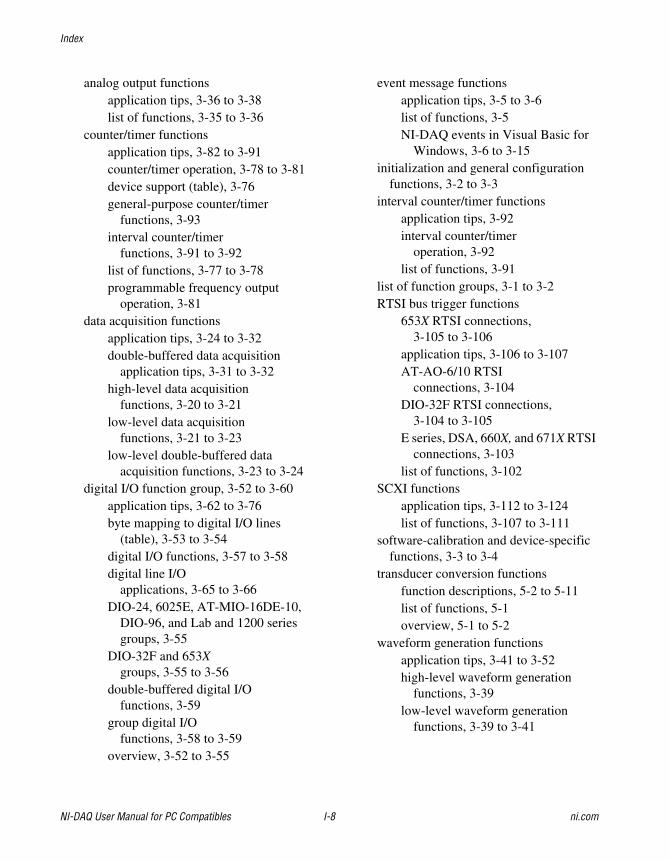
Index
NI-DAQ User Manual for PC Compatibles I-8 ni.com
analog output functionsapplication tips, 3-36 to 3-38list of functions, 3-35 to 3-36
counter/timer functionsapplication tips, 3-82 to 3-91counter/timer operation, 3-78 to 3-81device support (table), 3-76general-purpose counter/timer
functions, 3-93interval counter/timer
functions, 3-91 to 3-92list of functions, 3-77 to 3-78programmable frequency output
operation, 3-81data acquisition functions
application tips, 3-24 to 3-32double-buffered data acquisition
application tips, 3-31 to 3-32high-level data acquisition
functions, 3-20 to 3-21low-level data acquisition
functions, 3-21 to 3-23low-level double-buffered data
acquisition functions, 3-23 to 3-24digital I/O function group, 3-52 to 3-60
application tips, 3-62 to 3-76byte mapping to digital I/O lines
(table), 3-53 to 3-54digital I/O functions, 3-57 to 3-58digital line I/O
applications, 3-65 to 3-66DIO-24, 6025E, AT-MIO-16DE-10,
DIO-96, and Lab and 1200 seriesgroups, 3-55
DIO-32F and 653Xgroups, 3-55 to 3-56
double-buffered digital I/Ofunctions, 3-59
group digital I/Ofunctions, 3-58 to 3-59
overview, 3-52 to 3-55
event message functionsapplication tips, 3-5 to 3-6list of functions, 3-5NI-DAQ events in Visual Basic for
Windows, 3-6 to 3-15initialization and general configuration
functions, 3-2 to 3-3interval counter/timer functions
application tips, 3-92interval counter/timer
operation, 3-92list of functions, 3-91
list of function groups, 3-1 to 3-2RTSI bus trigger functions
653X RTSI connections,3-105 to 3-106
application tips, 3-106 to 3-107AT-AO-6/10 RTSI
connections, 3-104DIO-32F RTSI connections,
3-104 to 3-105E series, DSA, 660X, and 671X RTSI
connections, 3-103list of functions, 3-102
SCXI functionsapplication tips, 3-112 to 3-124list of functions, 3-107 to 3-111
software-calibration and device-specificfunctions, 3-3 to 3-4
transducer conversion functionsfunction descriptions, 5-2 to 5-11list of functions, 5-1overview, 5-1 to 5-2
waveform generation functionsapplication tips, 3-41 to 3-52high-level waveform generation
functions, 3-39low-level waveform generation
functions, 3-39 to 3-41
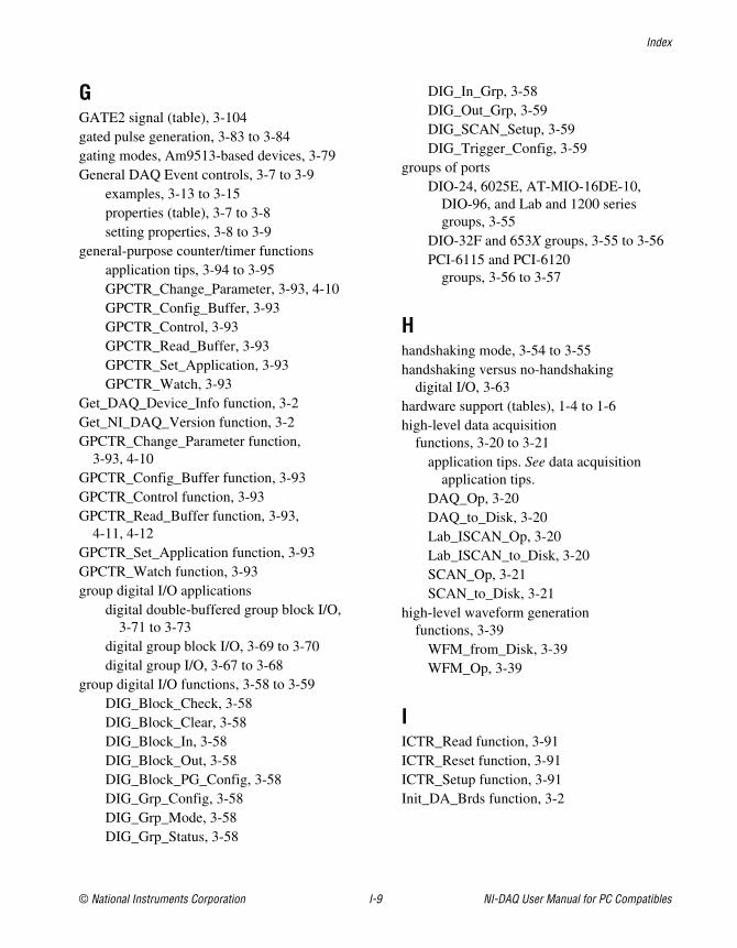
Index
© National Instruments Corporation I-9 NI-DAQ User Manual for PC Compatibles
GGATE2 signal (table), 3-104gated pulse generation, 3-83 to 3-84gating modes, Am9513-based devices, 3-79General DAQ Event controls, 3-7 to 3-9
examples, 3-13 to 3-15properties (table), 3-7 to 3-8setting properties, 3-8 to 3-9
general-purpose counter/timer functionsapplication tips, 3-94 to 3-95GPCTR_Change_Parameter, 3-93, 4-10GPCTR_Config_Buffer, 3-93GPCTR_Control, 3-93GPCTR_Read_Buffer, 3-93GPCTR_Set_Application, 3-93GPCTR_Watch, 3-93
Get_DAQ_Device_Info function, 3-2Get_NI_DAQ_Version function, 3-2GPCTR_Change_Parameter function,
3-93, 4-10GPCTR_Config_Buffer function, 3-93GPCTR_Control function, 3-93GPCTR_Read_Buffer function, 3-93,
4-11, 4-12GPCTR_Set_Application function, 3-93GPCTR_Watch function, 3-93group digital I/O applications
digital double-buffered group block I/O,3-71 to 3-73
digital group block I/O, 3-69 to 3-70digital group I/O, 3-67 to 3-68
group digital I/O functions, 3-58 to 3-59DIG_Block_Check, 3-58DIG_Block_Clear, 3-58DIG_Block_In, 3-58DIG_Block_Out, 3-58DIG_Block_PG_Config, 3-58DIG_Grp_Config, 3-58DIG_Grp_Mode, 3-58DIG_Grp_Status, 3-58
DIG_In_Grp, 3-58DIG_Out_Grp, 3-59DIG_SCAN_Setup, 3-59DIG_Trigger_Config, 3-59
groups of portsDIO-24, 6025E, AT-MIO-16DE-10,
DIO-96, and Lab and 1200 seriesgroups, 3-55
DIO-32F and 653X groups, 3-55 to 3-56PCI-6115 and PCI-6120
groups, 3-56 to 3-57
Hhandshaking mode, 3-54 to 3-55handshaking versus no-handshaking
digital I/O, 3-63hardware support (tables), 1-4 to 1-6high-level data acquisition
functions, 3-20 to 3-21application tips. See data acquisition
application tips.DAQ_Op, 3-20DAQ_to_Disk, 3-20Lab_ISCAN_Op, 3-20Lab_ISCAN_to_Disk, 3-20SCAN_Op, 3-21SCAN_to_Disk, 3-21
high-level waveform generationfunctions, 3-39
WFM_from_Disk, 3-39WFM_Op, 3-39
IICTR_Read function, 3-91ICTR_Reset function, 3-91ICTR_Setup function, 3-91Init_DA_Brds function, 3-2
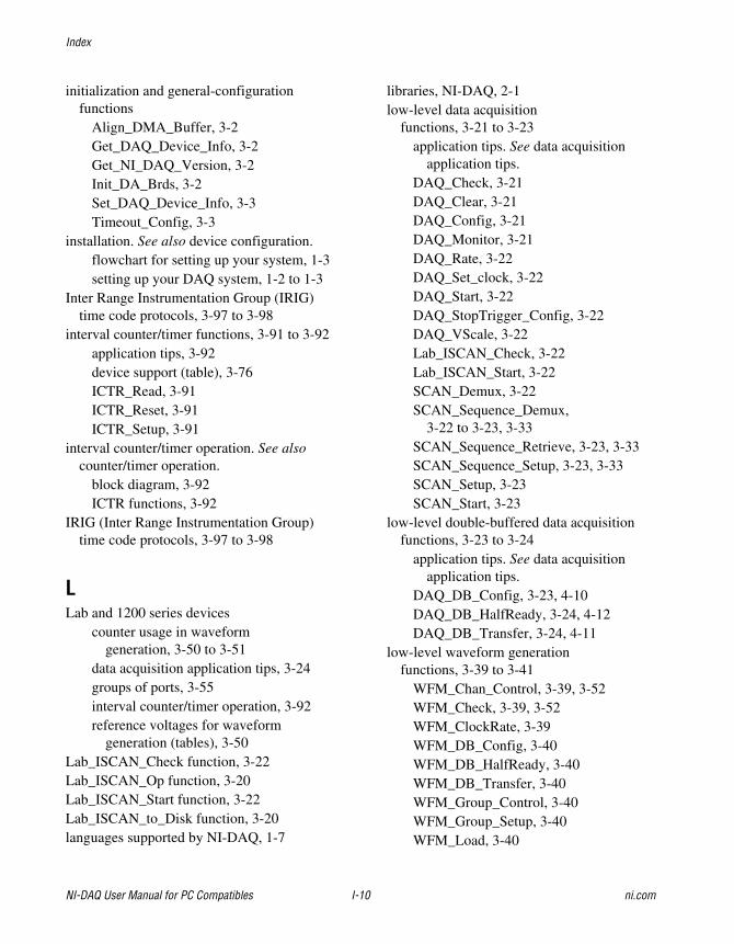
Index
NI-DAQ User Manual for PC Compatibles I-10 ni.com
initialization and general-configurationfunctions
Align_DMA_Buffer, 3-2Get_DAQ_Device_Info, 3-2Get_NI_DAQ_Version, 3-2Init_DA_Brds, 3-2Set_DAQ_Device_Info, 3-3Timeout_Config, 3-3
installation. See also device configuration.flowchart for setting up your system, 1-3setting up your DAQ system, 1-2 to 1-3
Inter Range Instrumentation Group (IRIG)time code protocols, 3-97 to 3-98
interval counter/timer functions, 3-91 to 3-92application tips, 3-92device support (table), 3-76ICTR_Read, 3-91ICTR_Reset, 3-91ICTR_Setup, 3-91
interval counter/timer operation. See alsocounter/timer operation.
block diagram, 3-92ICTR functions, 3-92
IRIG (Inter Range Instrumentation Group)time code protocols, 3-97 to 3-98
LLab and 1200 series devices
counter usage in waveformgeneration, 3-50 to 3-51
data acquisition application tips, 3-24groups of ports, 3-55interval counter/timer operation, 3-92reference voltages for waveform
generation (tables), 3-50Lab_ISCAN_Check function, 3-22Lab_ISCAN_Op function, 3-20Lab_ISCAN_Start function, 3-22Lab_ISCAN_to_Disk function, 3-20languages supported by NI-DAQ, 1-7
libraries, NI-DAQ, 2-1low-level data acquisition
functions, 3-21 to 3-23application tips. See data acquisition
application tips.DAQ_Check, 3-21DAQ_Clear, 3-21DAQ_Config, 3-21DAQ_Monitor, 3-21DAQ_Rate, 3-22DAQ_Set_clock, 3-22DAQ_Start, 3-22DAQ_StopTrigger_Config, 3-22DAQ_VScale, 3-22Lab_ISCAN_Check, 3-22Lab_ISCAN_Start, 3-22SCAN_Demux, 3-22SCAN_Sequence_Demux,
3-22 to 3-23, 3-33SCAN_Sequence_Retrieve, 3-23, 3-33SCAN_Sequence_Setup, 3-23, 3-33SCAN_Setup, 3-23SCAN_Start, 3-23
low-level double-buffered data acquisitionfunctions, 3-23 to 3-24
application tips. See data acquisitionapplication tips.
DAQ_DB_Config, 3-23, 4-10DAQ_DB_HalfReady, 3-24, 4-12DAQ_DB_Transfer, 3-24, 4-11
low-level waveform generationfunctions, 3-39 to 3-41
WFM_Chan_Control, 3-39, 3-52WFM_Check, 3-39, 3-52WFM_ClockRate, 3-39WFM_DB_Config, 3-40WFM_DB_HalfReady, 3-40WFM_DB_Transfer, 3-40WFM_Group_Control, 3-40WFM_Group_Setup, 3-40WFM_Load, 3-40
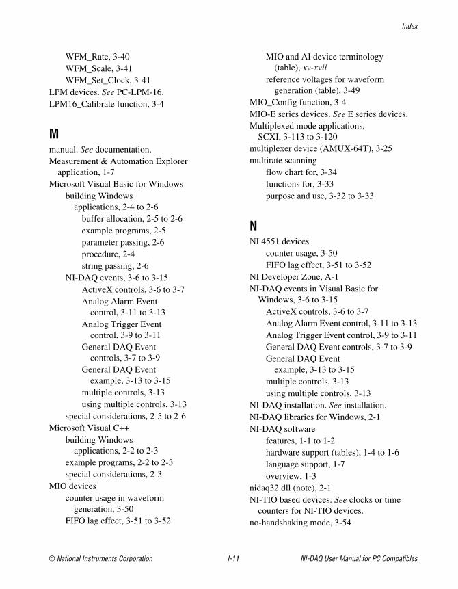
Index
© National Instruments Corporation I-11 NI-DAQ User Manual for PC Compatibles
WFM_Rate, 3-40WFM_Scale, 3-41WFM_Set_Clock, 3-41
LPM devices. See PC-LPM-16.LPM16_Calibrate function, 3-4
Mmanual. See documentation.Measurement & Automation Explorer
application, 1-7Microsoft Visual Basic for Windows
building Windowsapplications, 2-4 to 2-6
buffer allocation, 2-5 to 2-6example programs, 2-5parameter passing, 2-6procedure, 2-4string passing, 2-6
NI-DAQ events, 3-6 to 3-15ActiveX controls, 3-6 to 3-7Analog Alarm Event
control, 3-11 to 3-13Analog Trigger Event
control, 3-9 to 3-11General DAQ Event
controls, 3-7 to 3-9General DAQ Event
example, 3-13 to 3-15multiple controls, 3-13using multiple controls, 3-13
special considerations, 2-5 to 2-6Microsoft Visual C++
building Windowsapplications, 2-2 to 2-3
example programs, 2-2 to 2-3special considerations, 2-3
MIO devicescounter usage in waveform
generation, 3-50FIFO lag effect, 3-51 to 3-52
MIO and AI device terminology(table), xv-xvii
reference voltages for waveformgeneration (table), 3-49
MIO_Config function, 3-4MIO-E series devices. See E series devices.Multiplexed mode applications,
SCXI, 3-113 to 3-120multiplexer device (AMUX-64T), 3-25multirate scanning
flow chart for, 3-34functions for, 3-33purpose and use, 3-32 to 3-33
NNI 4551 devices
counter usage, 3-50FIFO lag effect, 3-51 to 3-52
NI Developer Zone, A-1NI-DAQ events in Visual Basic for
Windows, 3-6 to 3-15ActiveX controls, 3-6 to 3-7Analog Alarm Event control, 3-11 to 3-13Analog Trigger Event control, 3-9 to 3-11General DAQ Event controls, 3-7 to 3-9General DAQ Event
example, 3-13 to 3-15multiple controls, 3-13using multiple controls, 3-13
NI-DAQ installation. See installation.NI-DAQ libraries for Windows, 2-1NI-DAQ software
features, 1-1 to 1-2hardware support (tables), 1-4 to 1-6language support, 1-7overview, 1-3
nidaq32.dll (note), 2-1NI-TIO based devices. See clocks or time
counters for NI-TIO devices.no-handshaking mode, 3-54
Index
NI-DAQ User Manual for PC Compatibles I-12 ni.com
Oone-shot analog input functions, 3-16 to 3-19
AI_Change_Parameter, 3-16AI_Check, 3-16AI_Clear, 3-16AI_Configure, 3-16AI_Mux_Config, 3-17AI_Read, 3-17AI_Read_Scan, 3-17AI_Read_VScan, 3-17AI_Setup, 3-17AI_VRead, 3-17AI_VScale, 3-17application tips, 3-17 to 3-19
one-shot analog output functionsAO_Change_Parameter, 3-35AO_Configure, 3-35AO_Update, 3-35AO_VScale, 3-36AO_VWrite, 3-36AO_Write, 3-36application tips, 3-36 to 3-38
OUT0* signal (table), 3-104OUT1* signal (table), 3-104OUT2* signal (table), 3-104
PParallel mode applications, SCXI
modules, 3-120 to 3-124parameter passing in Windows applications
Microsoft Visual Basic, 2-6Microsoft Visual C++, 2-3
pattern generation I/O with DIO-32F, 653X,PCI-6115, and PCI-6120devices, 3-74 to 3-75
PC-DIO-24 groups of ports, 3-55PC-DIO-96 groups of ports, 3-55
PCI-4451 devicescounter usage, 3-50FIFO lag effect, 3-51 to 3-52
PCI-6115 and PCI-6120 devicesgroups of ports, 3-56 to 3-57pattern generation, 3-74 to 3-75
PCLK1 signal (table), 3-105PCLK2 signal (table), 3-105PC-LPM-16
counter/timer signals, 3-25interval counter/timer operation, 3-92LPM16_Calibrate function, 3-4
period and continuous pulse-widthmeasurement applications, 3-89 to 3-91
plug-in device supportAT, PC and NEC buses (table), 1-4PC Card, CardBus, and VXI buses
(table), 1-5PCI buses (table), 1-4PXI buses (table), 1-5
programmable frequency outputoperation, 3-81
pulse generationapplication tips, 3-83 to 3-84CTR_Pulse function, 3-77flow chart, 3-83retriggerable one-shot pulse, 3-84
pulse per secondsynchronization, 3-96 to 3-97
pulse width measurementevent-counting application, 3-86 to 3-87period and continuous pulse-width
measurement applications,3-89 to 3-91
Rreference voltages for analog output devices
bipolar output polarity(table), 3-49 to 3-50
unipolar output polarity (table), 3-49
Index
© National Instruments Corporation I-13 NI-DAQ User Manual for PC Compatibles
REQ1 signal653X RTSI connections (table), 3-105DIO-32F RTSI connections (table), 3-104
REQ2 signal653X RTSI connections (table), 3-105DIO-32F RTSI connections (table), 3-104
retriggerable one-shot pulse, 3-84RTD_Buf_Convert function, 5-2 to 5-4RTD_Convert function
definition, 5-1purpose and use, 5-2 to 5-4
RTSI busapplication tips, 3-106 to 3-107description, 3-102 to 3-103
RTSI bus connections, 3-103 to 3-106653X devices, 3-105 to 3-106AT-AO-6/10, 3-104DIO-32F, 3-104 to 3-105E series, DSA, 660XX, and 671X, 3-103
RTSI bus trigger functionsRTSI_Clear, 3-102RTSI_Clock, 3-102RTSI_Conn, 3-102RTSI_DisConn, 3-102Select_Signal, 3-102
SSCAN_Demux function, 3-22SCAN_Op function, 3-21SCAN_Sequence_Demux function,
3-22 to 3-23, 3-33SCAN_Sequence_Retrieve function,
3-23, 3-33SCAN_Sequence_Setup function, 3-23, 3-33SCAN_Setup function, 3-23SCAN_Start function, 3-23SCAN_to_Disk function, 3-21SCXI application tips, 3-112 to 3-124
analog output applications, 3-126data acquisition rates, 3-124 to 3-126
digital applications, 3-127general SCXIbus application
flowchart, 3-112Multiplexed mode, 3-113 to 3-120Parallel mode, 3-120 to 3-124SCXI-1200 module settling rates
(table), 3-126settling rates (table), 3-125settling times (table), 3-125
SCXI functions, 3-107 to 3-111SCXI_AO_Write, 3-107SCXI_Cal_Constants, 3-107SCXI_Calibrate, 3-107 to 3-108SCXI_Calibrate_Setup, 3-108SCXI_Change_Chan, 3-108SCXI_Configure_Connection, 3-108SCXI_Configure_Filter, 3-108SCXI_Get_Chassis_Info, 3-109SCXI_Get_Module_Info, 3-109SCXI_Get_State, 3-109SCXI_Get_Status, 3-109SCXI_Load_Config, 3-109SCXI_ModuleID_Read, 3-109SCXI_MuxCtr_Setup, 3-110SCXI_Reset, 3-110SCXI_Scale, 3-110SCXI_SCAN_Setup, 3-110SCXI_Set_Config, 3-110SCXI_Set_Excitation, 3-110SCXI_Set_Gain, 3-111SCXI_Set_Input_Mode, 3-111SCXI_Set_State, 3-111SCXI_Set_Threshold, 3-111SCXI_Single_Chan_Setup, 3-111SCXI_Track_Hold_Control, 3-111SCXI_Track_Hold_Setup, 3-111
SCXI_Calibrate function, 3-4, 3-107 to 3-108Select_Signal function, 3-4, 3-102Set_DAQ_Device_Info function, 3-3setting up DAQ systems. See device
configuration; installation.
Index
NI-DAQ User Manual for PC Compatibles I-14 ni.com
simultaneous counter operations (figure), 3-85single-buffered versus double-buffered
data, 4-1 to 4-2single-channel analog input
functions, 3-16 to 3-19AI_Change_Parameter, 3-16AI_Check, 3-16AI_Clear, 3-16AI_Configure, 3-16AI_Mux_Config, 3-17AI_Read, 3-17AI_Read_Scan, 3-17AI_Read_VScan, 3-17AI_Setup, 3-17AI_VRead, 3-17AI_VScale, 3-17application tips, 3-17 to 3-19
software-calibration and device-specificfunctions, 3-3 to 3-4
AO_Calibrate, 3-3Calibrate_1200, 3-3 to 3-4Calibrate_DSA, 3-4Calibrate_E_Series, 3-4Calibrate_TIO, 3-4Configure_HW_Analog_Trigger, 3-4LPM16_Calibrate, 3-4MIO_Config, 3-4SCXI_Cal_Constants, 3-107SCXI_Calibrate, 3-4, 3-107 to 3-108SCXI_Calibrate_Setup, 3-108Select_Signal, 3-4, 3-102
square wave generation functions, 3-84STOPTRIG1 signal (table), 3-105STOPTRIG2 signal (table), 3-105Strain_Buf_Convert function, 5-4 to 5-6Strain_Convert function
definition, 5-1purpose and use, 5-4 to 5-6
string passing in Windows applicationsMicrosoft Visual Basic, 2-6Microsoft Visual C++, 2-3
synchronization of clocks. See clocks or timecounters for NI-TIO devices.
system integration, by NationalInstruments, A-1
Ttechnical support resources, A-1 to A-2Thermistor_Buf_Convert function, 5-7 to 5-9Thermistor_Convert function
definition, 5-1purpose and use, 5-7 to 5-9
Thermocouple_Buf_Convertfunction, 5-9 to 5-11
Thermocouple_Convert functiondefinition, 5-1purpose and use, 5-9 to 5-11
time counters. See clocks or time counters forNI-TIO devices.
time-lapse measurement, 3-87Timeout_Config function, 3-3transducer conversion functions, 5-1 to 5-11
overview, 5-1 to 5-2RTD_Buf_Convert, 5-2 to 5-4RTD_Convert, 5-1, 5-2 to 5-4Strain_Buf_Convert, 5-4 to 5-6Strain_Convert, 5-1, 5-4 to 5-6Thermistor_Buf_Convert, 5-7 to 5-9Thermistor_Convert, 5-1, 5-7 to 5-9Thermocouple_Buf_Convert, 5-9 to 5-11Thermocouple_Convert, 5-1, 5-9 to 5-11
VVisual Basic. See Microsoft Visual Basic for
Windows.
Index
© National Instruments Corporation I-15 NI-DAQ User Manual for PC Compatibles
Wwaveform generation application
tips, 3-41 to 3-52basic applications, 3-41 to 3-43basic waveform generation with
pauses, 3-44 to 3-46counter usage, 3-50 to 3-51double-buffered
applications, 3-47 to 3-48external triggering, 3-52FIFO lag effect, 3-51 to 3-52minimum update intervals, 3-50reference voltages for analog
output devicesbipolar output polarity
(table), 3-49 to 3-50unipolar output polarity (table), 3-49
waveform generation functions, 3-39 to 3-41high-level waveform generation
functions, 3-39WFM_from_Disk, 3-39WFM_Op, 3-39
low-level waveform generationfunctions, 3-39 to 3-41
WFM_Chan_Control, 3-39, 3-52WFM_Check, 3-39, 3-52WFM_ClockRate, 3-39WFM_DB_Config, 3-40, 4-10WFM_DB_HalfReady, 3-40, 4-12WFM_DB_Transfer, 3-40, 4-11WFM_Group_Control, 3-40WFM_Group_Setup, 3-40WFM_Load, 3-40WFM_Rate, 3-40WFM_Scale, 3-41WFM_Set_Clock, 3-41
Web support from National Instruments, A-1WFM_Chan_Control function, 3-39, 3-52WFM_Check function, 3-39, 3-52WFM_ClockRate function, 3-39WFM_DB_Config function, 3-40, 4-10WFM_DB_HalfReady function, 3-40, 4-12WFM_DB_Transfer function, 3-40, 4-11WFM_from_Disk function, 3-39WFM_Group_Control function, 3-40WFM_Group_Setup function, 3-40WFM_Load function, 3-40WFM_Op function, 3-39WFM_Rate function, 3-40WFM_Scale function, 3-41WFM_Set_Clock function, 3-41Windows applications, building, 2-1 to 2-10
Borland C++, 2-7 to 2-8Borland Delphi, 2-8Microsoft Visual Basic, 2-4 to 2-6Microsoft Visual C++, 2-2 to 2-3NI-DAQ examples, 2-9 to 2-10NI-DAQ libraries, 2-1
Worldwide technical support, A-2