Embed Size (px)
DESCRIPTION
The increasing complexity of networks and NMSs is starting to affect operators, who are seeing a growing demand for Dynamic VPNs. DVPNs are application-specific VPNs which can be altered multiple time over their potentially short lifetime, requiring a certain degree of flexibility and agility from the network and its support systems.To implement DVPNs in the network, operators need to solve the complexity of NMSs and allow for granular control over network resources. A possible candidate to provide this solution is the SDN architecture and the OpenFlow specification. However, it is unclear if this solution will actually provide any benefit over the use of state of the art technologies.
Citation preview
MSC SYSTEMS & NETWORK ENGINEERING
Architecture of dynamic VPNs in OpenFlow
By:Michiel [email protected]
Supervisor:Rudolf STRIJKERS
July 17, 2013

Abstract
The increasing complexity of networks and NMSs is starting to affect operators, who are seeing a growingdemand for Dynamic VPNs. DVPNs are application-specific VPNs which can be altered multiple time overtheir potentially short lifetime, requiring a certain degree of flexibility and agility from the network and itssupport systems.
To implement DVPNs in the network, operators need to solve the complexity of NMSs and allow for granularcontrol over network resources. A possible candidate to provide this solution is the SDN architecture andthe OpenFlow specification. However, it is unclear if this solution will actually provide any benefit over theuse of state of the art technologies.
This research compares the differences between implementing a DVPN service using the contemporaryMPLS stack and implementing it using OpenFlow. We found that the MPLS implementation can providethe VPN service but due to its large protocol stack and lack of a defined management interface, will prove tobe unsuitable when implementing DVPNs.
On the other hand, the SDN architecture can solve complexity and provide manageability by providingnetwork abstractions to applications which can be developed by the operators themselves. However, untilthe northbound and east/westbound interfaces are defined, portability and flexibility is still limited.
Additionally, this research shows that OpenFlow is missing monitoring in its forwarding plane allowing forindividual components to make independent choices to provide fast failover times. This limitation meansthat the networking devices will need support from the controller to detect faults in the path, yielding recov-ery times above operator requirements.
i
Contents
Abstract i
1 Introduction 11.1 Research Question . . . . . . . . . . . . . . . . . . . . . . . . . . . . . . . . . . . . . . . . . . . . 11.2 Scope . . . . . . . . . . . . . . . . . . . . . . . . . . . . . . . . . . . . . . . . . . . . . . . . . . . . 21.3 Approach . . . . . . . . . . . . . . . . . . . . . . . . . . . . . . . . . . . . . . . . . . . . . . . . . . 2
2 Definition of a Dynamic VPN (DVPN) 32.1 VPNs . . . . . . . . . . . . . . . . . . . . . . . . . . . . . . . . . . . . . . . . . . . . . . . . . . . . 32.2 DVPNs . . . . . . . . . . . . . . . . . . . . . . . . . . . . . . . . . . . . . . . . . . . . . . . . . . . 6
3 Architecture 73.1 MPLS . . . . . . . . . . . . . . . . . . . . . . . . . . . . . . . . . . . . . . . . . . . . . . . . . . . . 73.2 OpenFlow . . . . . . . . . . . . . . . . . . . . . . . . . . . . . . . . . . . . . . . . . . . . . . . . . 9
4 Comparison 134.1 Service . . . . . . . . . . . . . . . . . . . . . . . . . . . . . . . . . . . . . . . . . . . . . . . . . . . 134.2 Transport . . . . . . . . . . . . . . . . . . . . . . . . . . . . . . . . . . . . . . . . . . . . . . . . . . 134.3 Provisioning . . . . . . . . . . . . . . . . . . . . . . . . . . . . . . . . . . . . . . . . . . . . . . . . 144.4 DVPNs . . . . . . . . . . . . . . . . . . . . . . . . . . . . . . . . . . . . . . . . . . . . . . . . . . . 14
5 Conclusion 165.1 Recommendations . . . . . . . . . . . . . . . . . . . . . . . . . . . . . . . . . . . . . . . . . . . . 175.2 Future Work . . . . . . . . . . . . . . . . . . . . . . . . . . . . . . . . . . . . . . . . . . . . . . . . 18
Appendices
A Related Work 19A.1 ATM . . . . . . . . . . . . . . . . . . . . . . . . . . . . . . . . . . . . . . . . . . . . . . . . . . . . 19A.2 SPB . . . . . . . . . . . . . . . . . . . . . . . . . . . . . . . . . . . . . . . . . . . . . . . . . . . . . 19
B Acronyms 21
C Bibliography 22
ii

List of Figures
1 Visualization of used terminology. . . . . . . . . . . . . . . . . . . . . . . . . . . . . . . . . . . . 32 DVPN traffic as it travels through the provider network. . . . . . . . . . . . . . . . . . . . . . . 43 Processing of ARP requests at the Provider Edge device (PE). . . . . . . . . . . . . . . . . . . . . 84 Dependency stack of Multi Protocol Label Switching (MPLS)-related technologies. . . . . . . . 85 Provisioning a DVPN using MPLS. . . . . . . . . . . . . . . . . . . . . . . . . . . . . . . . . . . . 96 Architecture of Software Defined Networking (SDN) and OpenFlow. . . . . . . . . . . . . . . . 107 Provisioning a DVPN using OpenFlow. . . . . . . . . . . . . . . . . . . . . . . . . . . . . . . . . 108 Interactions between application components to implement DVPNs. . . . . . . . . . . . . . . . 129 The proposed OpenDaylight architecture. . . . . . . . . . . . . . . . . . . . . . . . . . . . . . . . 1710 Provisioning a DVPN using Shortest Path Bridging (SPB). . . . . . . . . . . . . . . . . . . . . . 20
List of Tables
1 Feature requirements available in discussed technologies. . . . . . . . . . . . . . . . . . . . . . . 13
iii

Introduction Chapter 1
1 Introduction
Network operators today use Network Management Systems (NMSs) to get control over their devices andservices that they deploy. These systems have been customized to their needs and in general perform theirfunctionalities adequately. However, operators run into obstacles when trying to expand their businessportfolio by adding new services. This will potentially require a) new Application Programming Interface(API) calls to be implemented towards their NMS, b) their NMS to be able to cope with potentially newprotocols, and c) added expertise by engineers to define the possible feature interactions and restrictions ofthese protocols [1]. This limits the flexibility of the operators network when deploying new or adjustingexisting services.
To manage resources efficiently in a carrier network operators have been using Virtual Private Networks(VPNs) to connect customers. By differentiating traffic between VPNs they can control their traffic flow at agranular level. However, the set of interactions between different protocols and management interfaces tothem are complex. Setting up a VPN requires expertise and a significant amount of changes to the protocolsin the stack which are required to provide the service.
Until recently operators were not concerned by the inflexibility in their services as their networks were infact primarily static. However, the demand for application specific networks (e.g. video, voice or paymentnetworks) is growing. Therefore operators are looking for a more flexible approach in the form of DynamicVPNs (DVPNs). DVPNs are private networks over which end-users can communicate which are deployedby their common Service Provider (SP). They differ from normal VPNs in the sense that they can be alteredmultiple time over their potentially short lifetime. Using DVPNs, SPs can react more rapidly to customerrequests to configure, adjust or tear down their VPNs. However, due to management complexity DVPNsservices have not been implemented on a large scale.
A potential candidate to solve the complexity of implementing DVPNs is OpenFlow [2] and Software De-fined Networking (SDN). SDN is an architecture that allows for the programmability of the control planeof networking devices. The architecture is not standardized but a generalized structure has been given inthe OpenDaylight project [3]. OpenFlow is a lower level and increasingly supported API protocol towardsnetworking devices. Implementing the SDN architecture promises a) CAPEX savings due to hardware beingmore generic and flexible, b) OPEX savings because of the integration of NMSs and the control interface ofthe devices, thereby increasing automation, and c) increased network agility by using the open interfaces toprogram network devices directly [4].
The momentum that SDN is getting can be explained by a general need for change in the networking in-dustry. Operators primarily want to get more control over their networks, something which using the cur-rent stack of protocols is relatively complicated to get. The original OSI reference model [5] touches on the“Management Aspects” of each layer in the model, a way for management entities in the highest layer tocontrol the behavior of lower layers. Unfortunately in the swift evolution of Transmission Control Proto-col (TCP)/Internet Protocol (IP), these management interfaces are often limited or absent all together.
1.1 Research Question
In the case of DVPNs it is unclear if and how a real-world OpenFlow and SDN implementation will actuallyprovide any simplicity, additional flexibility or cost savings when compared to contemporary technologies[1]. And so the question arises: “How much can operators benefit from using OpenFlow when implement-ing Dynamic VPNs in comparison with contemporary technologies?” This requires research into whetherDVPNs can be implemented with current technologies, as well as with OpenFlow. Finally we will make acomparison between the two architectures.
1

Introduction Chapter 1
1.2 Scope
The focus will primarily be on deploying Provider-provisioned VPNs (PPVPNs) at Layer 2 of the OSI-modelbetween end-users. We haven chosen to do so because these Ethernet VPNs are characterized by their trans-parency to the end-user, who will be placed in a single broadcast domain with its peers and can thus com-municate directly without configuring any sort of routing. Furthermore, the provider will also be mostlyagnostic to the use of the customer, who can choose to use IPv4 or IPv6.
Previous research in [6] has proposed an implementation for programmable networks to deploy on-demandVPNs but it predates the OpenFlow specification, and also omits a comparison with how this would lookusing contemporary technologies.
1.3 Approach
In the Section 2 we will define the conceptual design of DVPNs. This will result in a list of required featuresfor the technologies to provide such a service. Section 3 will list the technologies available and will addition-ally determine their usability for implementing DVPNs when taking into account the requirements set forthin Section 2. In Section 4 we will distill the advantages and limitations of the different implementations andexplain how they compare to each other. Finally, Section 5 summarizes the results and provides a discussionand future work on this subject.
2
Definition of a DVPN Chapter 2
2 Definition of a DVPN
To define the DVPN service, we first take a look at the concepts of non-dynamic, or static VPNs. This sectionwill start by defining what a standard VPN service looks like, how it’s carried over the provider networkand the information needed to implement it. Next we will look at how these traditional VPN services can beevolved into Dynamic VPNs.
2.1 VPNs
2.1.1 Service
VPNs can be classified depending on the OSI layer which it virtualizes, the protocol that is being used andthe visibility to the customer. In an IPSec VPN for example, the customer needs to setup his Customer Edgedevices (CEs) at each site to actually establish the Layer 3 IP VPN. As we have already established in Sec-tion 1.2, we limit the use-case to an multi-point Ethernet Layer 2 VPN which is provisioned by the provider(PPVPN) and thus requires no action on the CE. Primarily because these Ethernet VPNs are characterized bytheir transparency to the end-user, requiring no routing information from them, and the fact that the clientcan choose to use IPv4 or IPv6. Throughout this paper the definition of PPVPN related terms will be used asdescribed in RFC 4026 [7] and an overview is given in Figure 1a.
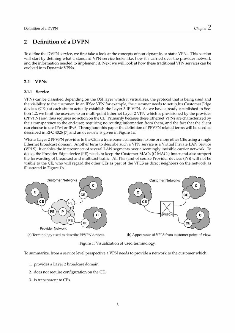
What a Layer 2 PPVPN provides to the CE is a transparent connection to one or more other CEs using a singleEthernet broadcast domain. Another term to describe such a VPN service is a Virtual Private LAN Service(VPLS). It enables the interconnect of several LAN segments over a seemingly invisible carrier network. Todo so, the Provider Edge device (PE) needs to keep the Customer MACs (C-MACs) intact and also supportthe forwarding of broadcast and multicast traffic. All PEs (and of course Provider devices (Ps)) will not bevisible to the CE, who will regard the other CEs as part of the VPLS as direct neighbors on the network asillustrated in Figure 1b.
CE
C
CE
C
Customer Networks
CE
C
Provider Network
PE
PE
PE
P
(a) Terminology used to describe PPVPN devices.
CE
C
CE
C
Customer Networks
CE
C
SWITCH
(b) Appearance of VPLS from customer point-of-view.
Figure 1: Visualization of used terminology.
To summarize, from a service level perspective a VPN needs to provide a network to the customer which:
1. provides a Layer 2 broadcast domain,
2. does not require configuration on the CE,
3. is transparent to CEs.
3
Definition of a DVPN Chapter 2
2.1.2 Transport
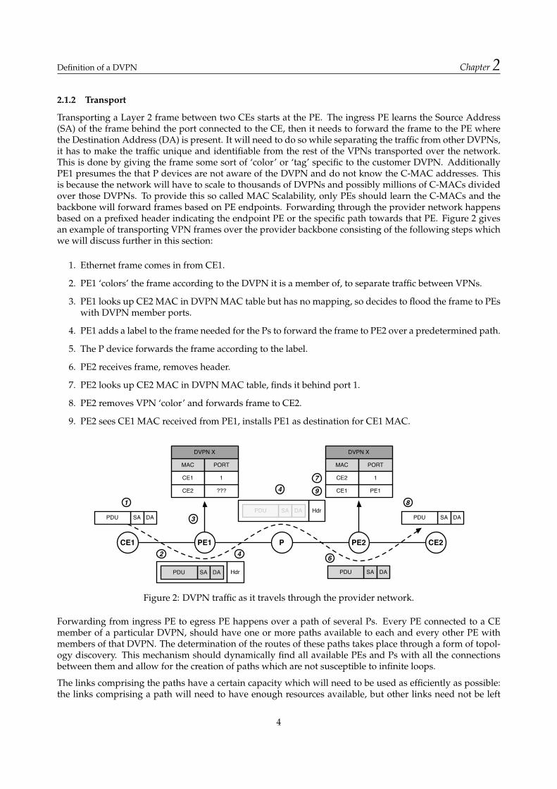
Transporting a Layer 2 frame between two CEs starts at the PE. The ingress PE learns the Source Address(SA) of the frame behind the port connected to the CE, then it needs to forward the frame to the PE wherethe Destination Address (DA) is present. It will need to do so while separating the traffic from other DVPNs,it has to make the traffic unique and identifiable from the rest of the VPNs transported over the network.This is done by giving the frame some sort of ‘color’ or ‘tag’ specific to the customer DVPN. AdditionallyPE1 presumes the that P devices are not aware of the DVPN and do not know the C-MAC addresses. Thisis because the network will have to scale to thousands of DVPNs and possibly millions of C-MACs dividedover those DVPNs. To provide this so called MAC Scalability, only PEs should learn the C-MACs and thebackbone will forward frames based on PE endpoints. Forwarding through the provider network happensbased on a prefixed header indicating the endpoint PE or the specific path towards that PE. Figure 2 givesan example of transporting VPN frames over the provider backbone consisting of the following steps whichwe will discuss further in this section:
1. Ethernet frame comes in from CE1.
2. PE1 ‘colors’ the frame according to the DVPN it is a member of, to separate traffic between VPNs.
3. PE1 looks up CE2 MAC in DVPN MAC table but has no mapping, so decides to flood the frame to PEswith DVPN member ports.
4. PE1 adds a label to the frame needed for the Ps to forward the frame to PE2 over a predetermined path.
5. The P device forwards the frame according to the label.
6. PE2 receives frame, removes header.
7. PE2 looks up CE2 MAC in DVPN MAC table, finds it behind port 1.
8. PE2 removes VPN ‘color’ and forwards frame to CE2.
9. PE2 sees CE1 MAC received from PE1, installs PE1 as destination for CE1 MAC.
SA
CE1 PE1 P PE2 CE2
DAPDU
SA DAPDU SA DAPDU
SA DAPDU
Hdr
SA DA PDU Hdr
MAC PORT
CE1 1
MAC PORT
CE2 1
CE1 PE1CE2 ???
DVPN X DVPN X
1
2
3
4
4
6
7
8
9
Figure 2: DVPN traffic as it travels through the provider network.
Forwarding from ingress PE to egress PE happens over a path of several Ps. Every PE connected to a CEmember of a particular DVPN, should have one or more paths available to each and every other PE withmembers of that DVPN. The determination of the routes of these paths takes place through a form of topol-ogy discovery. This mechanism should dynamically find all available PEs and Ps with all the connectionsbetween them and allow for the creation of paths which are not susceptible to infinite loops.
The links comprising the paths have a certain capacity which will need to be used as efficiently as possible:the links comprising a path will need to have enough resources available, but other links need not be left
4

Definition of a DVPN Chapter 2
vacant. Also, if the required bandwidth for a DVPN exceeds the maximum capacity of one or more of thelinks in a single path, a second path should be installed to share the load towards the egress PE. In short, thetraffic going over the provide backbone should be tightly managed to prevent congestion.
Continuing with the processing of the ingress customer frame, when it arrives at the ingress PE with a DAunknown to the PE, the frame will be flooded to all PEs participating in the VPN. Upon arrival there, theegress PE stores the mapping of the frames SA to the ingress PE and if it knows the DA will forward outthe appropriate port. Figure 2 shows this at points 3 and 8, 10 displaying the contents of the Media AccessControl (MAC) address table of both PEs. Because the DVPN is a virtual broadcast domain, all Broadcast,Unknown unicast and Multicast (BUM) traffic will need to be flooded to the participating PEs. To limit theamount of BUM traffic in a single DVPN rate limits or filters will need to be in place to prevent the DVPNfrom being flooded with it.
With multiple DVPNs present on the network it can happen that one DVPN affects the available bandwidthof others. Therefore rate limits will need to be in place for the overall traffic coming in to the CE-connectedports.
By assigning a minimum and maximum bandwidth rate to each DVPN instance, it is possible to preprovisionpaths over the network according to the required bandwidth. By also monitoring the utilization of individuallinks, DVPN paths can be moved away from over-provisioned links while they are in use. However, theimpact on traffic when performing such a switch must be minimized and should ideally last no longer than50 ms.
To monitor and troubleshoot large carrier networks Operations, Administration and Management (OAM)functionalities need to be supported by the network. Monitoring end-to-end activity needs to availablethrough automatic continuity check messages, but also by supporting ‘traceroutes’ through the networkmanually. This enables the network react proactively to network failures by using a similar method aspresented above when switching DVPNs to a different path, also known as ‘fast failover.’
To sum up the requirements discussed in this section, the network needs to provide the following function-alities:
1. identify traffic from separate DVPNs by tagging,
2. scalable up to thousands of DVPNs and C-MACs,
3. topology discovery,
4. provision paths over the network,
5. efficient use of, and control over all network resources (Traffic Engineering (TE)),
6. share the load of traffic over multiple paths,
7. rate limiting or filtering of BUM traffic,
8. rate limiting of total DVPN traffic per port,
9. fast failover times (<50ms) to provide continuity to critical applications,
10. provide Operations, Administration and Management features to monitor and troubleshoot the net-work.
2.1.3 Provisioning
A VPN service consists of multiple member ports, which are identified by their PE device and the porton that PE. The service is also defined by its minimum and maximum available bandwidth which can beused to determine the paths that the VPN will get assigned. When member ports reside on different PEs, apath will need to be created through the network. The route of the path will depend on a) the liveness and
5

Definition of a DVPN Chapter 2
administrative availability of the links, b) the administrative costs of the links, and c) the resources availableon the links towards the PE. The exact algorithm used to choose the paths lies outside of the scope of thisdocument. Paths are defined by the physical ports that they traverse through the network, with the PEs asthe first or last in the list.
More paths may be added over different routes and paths may be adjusted during the lifetime of the VPN.This may for example be necessary when a certain link in the path fails, or when it nears its peak capacityand has to be rerouted. Individual port utilization will be monitored and when a certain link shows highutilization, the corresponding paths and VPNs using those paths can be looked up using the informationbase. Also other monitoring and troubleshooting processes will profit from this information.
After the paths between the PEs with VPN members have been setup the traffic can start flowing. However,as has been mentioned before, the rate limiting feature will need to be applied to the ingress ports to preventthe VPN from using up all the networks resources.
To provision VPNs in the network, the operator should be able to:
1. setup the base network required for VPN routing,
2. determine routes that can be used for the paths,
3. monitor links and reroute paths on failure or peak capacity,
4. set the rate limits on ingress PE ports.
2.2 DVPNs
The configurations of VPNs in currently in use in operator networks are mostly static and changes in thesenetworks require (manual) effort to provision them. To evolve from these inflexible VPN setups to DynamicVPNs the provisioning systems in use will need to support some additional features.
First, the implementation of DVPNs will be automated. This means that instead of the manual configurationby an engineer, the NMS will take care of configuring the network with the correct CE endpoint ports on allPEs, making sure that the paths are installed and verifying connectivity. This also includes calculation of theoptimal paths and setting the correct rate limits, similar to the requirement given in Section 2.1.3.
Second, the NMS is able to change the configuration of DVPNs when requested. Additionally when a DVPNis no longer in use, it will need to be automatically purged from the network to free up resources for otherservices. This requires the NMS to keep an overview of the provisioned DVPNs and can optionally set anidle time out for the service.
Finally, the changes in the network resources and DVPN requirements should be acted upon without manualintervention. When certain links are running low on available bandwidth or fail altogether, this will causea recalculation of the provisioned paths. Also, when new hardware is added, it will be configured to takepart in the network, immediately making use of its added resources. Similarly, when the requirements of aDVPN change, the NMS will verify that the current paths meet these requirements, or otherwise find newroutes to provision for the DVPNs.
To provide a DVPN service, the operator requires the following additional functionalities from the NMS:
1. Automated creation, modification and deletion of DVPNs,
2. Adapt to changes in the form of:
(a) deminishing resources,(b) added resources, and(c) changed requirements for DVPNs.
6

Architecture Chapter 3
3 Architecture
This section will first describe the technical details of Multi Protocol Label Switching (MPLS) with regardsto the features required for implementing DVPNs. We will design an architecture to implement this serviceand point out the limitations. Next, we will describe the SDN architecture and the OpenFlow specification.Also looking at the features they provide to implement a DVPN service. In Appendix A.2 we have also takena look at Asynchronous Transport Method (ATM) and Shortest Path Bridging (SPB), both are technologiesthat can be used to implement VPNs but are missing key requirements to support DVPNs.
3.1 MPLS
MPLS is known for its scalability and extensibility. Over the past decade additions have been made tothe original specification to overcome a plethora of issues within carrier networks. This initially startedwith trying to implement fast forwarding in legacy switches using labels (or tags) at the start of the frame[8]. When this issue became surmountable using new hardware, MPLS had already proven to be capableof transporting a wide arrange of protocols on the carrier backbone network, all the while also providingscalability, TE and Quality of Service (QoS) features to the operators.
MPLS itself is a technology for forwarding frames through the network, does not provide any additionalfunctionalities such as topology discovery, route determination, resource management, etc. These functionsare left to a stack of other protocols. Without IP reachability throughout the network these protocols cannotexchange traffic and so, as a prerequisite, MPLS relies on an Interior Gateway Protocol (IGP) like OpenShortest Path First (OSPF) to discovery the topology.
The distribution of labels has to be facilitated as well, which is done using Label Distribution Protocol (LDP)and/or Resource Reservation Protocol (RSVP). These protocols run between each device in the path betweentwo PEs and exchange the labels that the will assign to a certain path, thereby setting up a Label-switchedPath (LSP). The labels assigned are always of ‘local significance,’ meaning that the P/PE device that needsto forward the labels, will announce its own chosen labels. The LDP protocol does this by distributing itslabels from the egress PE up towards the ingress PE based on IGP costs. RSVP, on the other hand, signalsits paths from the ingress PE towards the downstream PE based on constraints, potential explicit hops oras a last resort using the IGP next hop. Label distribution is still determined from egress to ingress, but theactual path is determined at the head-end. To determine the best path to take, RSVP uses the ConstrainedShortest Path First (CSPF) algorithm which can take into account link characteristics like bandwidth or FastReroute (FRR) support. This allows RSVP LSPs to take more well informed paths through the network andtogether with support for defining explicit paths, allows for granular TE features which LDP lacks. BothLDP and RSVP also allow for the use of multiple paths over the network to share traffic load towards a PE.
The FRR feature is unique to RSVP and provides the network with fast failure recovery. It does so by pre-provisioning a so-called backup LSP next to the primary LSP. When a failure is detected on the primaryLSP, traffic is immediately shifted towards the standby path, yielding a sub-50ms failover. Obviously, thisvalue also depends on the time it takes for the failure to be detected. Therefore it is important to have somesort of detection mechanism in place. One that is commonly used and integrates with OSPF is BidirectionalForward Detection (BFD). This protocol sets up sessions between devices and triggers an alarm when thesession does not behave as expected. At which point FRR swaps the traffic to the preprovisioned backuppath. To differentiate traffic coming from a normal, ‘protected’ path and traffic taking a ‘detour’ path, FRRadds another MPLS tag to the MPLS label stack.
VPNs are also provided by additional protocols. Layer 3 VPNs make use of Border Gateway Protocol (BGP)to distribute client prefixes to the edges of the carrier network. The core is only concerned with the for-warding of labels and has now knowledge of these IP prefixes. Layer 2 VPNs make use of VPLS, a servicewhich encapsulates the entire Ethernet frame and pushes a label to it to map it to a certain separated net-work. Again, the core is only concerned with the labels and only the edges need to know the clients MACaddresses. When setting up a VPLS instance (a VPNs), LDP sessions are setup between all PEs part of the
7

Architecture Chapter 3
same VPLS instance. Consecutively, the PEs will exchange their chosen labels for that instance between eachother.
The C-MACs in a VPLS instance are normally learned through the data plane. That is, when a frame comesin from a CE, the PE learns the SA behind the corresponding port. If it doesn’t know the DA, it will floodthe frame to other PEs with member ports in that instance. These PEs in turn learn the SA as well behindthe ingress PE. This is also illustrated in Figure 2. When a large number of C-MACs are present withina VPLS instance this can cause a lot of broadcast traffic, specifically Address Resolution Protocol (ARP)traffic. To solve this, the Ethernet VPN (E-VPN) standard has been proposed [9]. This technique providesMAC learning in the control plane by exchanging learned C-MACs between PEs using Multi-Protocol BGP.Additionally it learns the IP addresses associated with the C-MACs and distributes those to other PEs. ThePEs are thereby able to act as an ARP proxy, as illustrated in Figure 3b.
CE PE PFLOOD
ARP Req
(a) Normal ARP Request.
CE PE P
IP - MAC Table
ARP Req
ARP ReplyLOOKUP
(b) ARP proxy in PE.
Figure 3: Processing of ARP requests at the PE.
The different protocols all depend on each other, as illustrated in Figure 4. Each PE device runs this stack,while P devices run a subset which is shaded.
LDP
OSPF
MP-BGP RSVP-TE BFD
FRR
E-VPN
VPLS
IP Addressing
Figure 4: Dependency stack of MPLS-related technologies.
To configure a DVPN using MPLS first the participating PEs need to be configured with the new VPLSinstance to which the member CE ports will be added. Next, constraints are defined by the NMS, which canbe in the form of an explicit route to make a static route or by defining loose constraints based on bandwidthlimits which can be used the CSPF algorithm. Using these constraints, paths are installed at each PE towardsevery other participating PE. These paths are then added to the VPLS instance, allowing LDP sessions tobe setup between the PEs. Next, for FRR, backup LSPs need to defined similarly to the primary LSP butover a different path, which can again be done using constraints to exclude the other links. Utilization of thelinks in the network has to be monitored as well and when a path has a link which is nearing capacity, newLSPs have to be provisioned and some VPLS paths move to those LSPs. And finally the ingress traffic onthe CE ports need to be rate limited. This procedure is not standardized and is dependent on support of thehardware.
The procedure above implies that the backbone network has been setup with the following protocols andfeatures already enabled: IP addressing, OSPF routing, MPLS forwarding, RSVP with FRR and BFD. Afterinitial setup of the backbone network the NMS is only concerned with the PEs, as can also be seen in Figure 5.However, the NMS needs to be aware of the PEs it needs to consult, the intermediate Ps if it wants to use TE,the network resources in the path and of course the actual member ports.
Implementing VPNs using MPLS has been shown to be possible using the protocols that have been engi-neered to provide all the required features. The technologies are built upon each other instead of being
8

Architecture Chapter 3
evolved upon. This causes their dependencies to grow more complex over time which in turn makes itdifficult for the NMS to deal with all the different protocols. Additionally, developing and maintaining anefficient NMS is also more difficult due to the lack of a common abstracted interface to the network devices.
VPLS
RSVPMPLS
RSVPMPLS
RSVPMPLS
RSVPMPLS
VPLS
CE PE P P PE CE
Forwarding Plane
Control Plane
NMSDATA
LDPLDP
Figure 5: Provisioning a DVPN using MPLS.
3.2 OpenFlow
Software Defined Networking is the general principle of designing flexible networks using open interfacestowards the hardware. OpenFlow is a subcomponent of this new principle which provides a protocol be-tween the forwarding plane of the networking devices and a centralized controller. A general overview ofthe SDN architecture and OpenFlow is given in Figure 6. OpenFlow provides the controller with an API thatcan be used to install flow entries directly in the forwarding plane of the devices. Flow entries consist of sixfields:
Match This field contains a list of frame/packet characteristics that will need to be present to matchto this entry, e.g. DA, IP source address or MPLS tags.
Priority The precedence of this flow entry over other flow entries to which a certain frame matches.
Counters Frames matching to this entry are counted for monitoring purposes.
Instructions When a frame is matched using the match field, it is processed according to a list of instructions,which may include forwarding out of a port, rewriting headers and/or applying meters.
Timeouts The time that a flow entry can be live until it is discarded.
Cookie Value assigned by controller to identify the flow (not used to forward frames).
The frame fields that can be matched upon have changed over the lifetime of the OpenFlow specification. Forexample, version 1.0 could only match and/or act upon tagged traffic using a single outer-VLAN tag. Version1.1 added matches and actions for Q-in-Q tags and MPLS labels, and version 1.3 could also match ProviderBackbone Bridging (PBB) tags. Also, rate limiting on a per port basis has been available in OpenFlow sinceversion 1.0. And version 1.3 added support for per flow rate limiting using so called ‘meters’ which can beassigned to specific flows. By doing so it becomes possible to also rate limit flows on certain aggregationports rather than just at the ingress port of the CE.
The installation of flow entries is done by the controller, governed by the applications running on it. Appli-cations can be written to provide functions like topology discovery, routing, etc. Moreover, without theseinstalled applications, the network will be unable to forward any traffic. The interface between the applica-tions and the controller is also being referred to as the ‘northbound interface’. This interface, in contrast to
9

Architecture Chapter 3
CONTROLLER
APP APP APP APP
Northbound
SouthboundOpenFlow
???
Figure 6: Architecture of SDN and OpenFlow.
the southbound OpenFlow interface, has not been specified and varies between different controller imple-mentations, limiting the portability of the network applications.
Unlike contemporary technologies that require inter-device communication before any paths can be set up,the forwarding tables of OpenFlow devices are empty. The only prerequisite is that the devices all have amanagement connection to the controller from which they can receive their forwarding information.
The controller is the combination of hardware and software components that are preferably setup redun-dantly and share a complete view of the network, which they share with the applications running on it.To provide the network and its control with redundancy in case of failures, the ‘controller’ component canrefer to a logical controller entity, not specifically a single physical server. However, the actual design andimplementation of such a system is beyond the scope of this paper.
Current OpenFlow versions are not yet supported by all controllers. We are inspecting version 1.3.1 of thespecification which supports the features described. However, at the time of writing there are only twocontrollers supporting the 1.3 version:
• Ryu by NTT [10], and
• NOX extensions by CPqD research center from Brazil [11].
The controller developed under the OpenDaylight project lacks support for version 1.3.
Implementing DVPNs using OpenFlow relies mostly on the applications running on the controller. Whenthey are written and configured as desired, provisioning a DVPN would only require the input of the data.After which the applications and controller install flow entries into all the network devices in the DVPNpath, as can be seen in Figure 7.
CE PE P P PE CE
Forwarding Plane
Control Plane
CONTROLLERDATA APPS
Figure 7: Provisioning a DVPN using OpenFlow.
10

Architecture Chapter 3
3.2.1 DVPN Provisioning
To implement DVPNs, one or more applications providing the functions analogous to contemporary imple-mentations need to be implemented in the OpenFlow setup:
Topology Discovery Network devices do not require IP connectivity between each other to exchange routeinformation. Instead, they rely on their connection to the controller to provide themwith information. A topology discovery application will instruct network devices tosend out unique discovery messages which are then received by other devices, whichforward the message back up to the controller. By keeping information on whichpacket goes in and comes out where, the application can get an overview of the net-work. By centralizing the topology discovery process, network operators can benefitfrom more efficient synchronization and faster convergence.
DVPN Provisioning The DVPN input will provide the application with at least the CE port and preferablythe corresponding MAC and/or IP address. It can then instruct the path provisioningcomponent to set up paths between all the PEs participating in the DVPN.
Path Provisioning Using the discovered topology, paths are setup over those routes between PEs withmember CE ports in a common DVPN. This means that the flow entries are installedproactively in the Ps and PEs when a DVPN is setup. Instead of waiting for one ofthem to send a message to the controller asking what to do with an unknown incom-ing frame, this proactive approach allows for better scalability (less requests to thecontroller) and faster initial forwarding (no buffering while consulting controller).
OAM The controller and applications provide a complete overview of the network but trou-bleshooting and monitoring still has to be done at the network level as well. Differentapproaches can be taken to do so, one of which could be sending out periodic keep-alive messages in the same path from the controller down to the ingress PE that theegress PE should forward back up to the controller. Another example is implement-ing an already defined OAM protocol in OpenFlow, as has been done in [12] whichimplemented Ethernet 802.1ag OAM.
Traffic Engineering The path setup procedure uses data from the DVPN input and the discovered networkresources to provide the most optimal path between two PEs. Constraints for the pathstaken by each DVPN can be configured by the operator and influence the route selec-tion directly over the whole platform. Also, using input from the OAM monitoringapplications paths may be preferred or deprecated based on their performance.
C-MAC Filtering This application is concerned with keeping the provided or dynamically learned MACaddresses up-to-date. Additionally, a flow can be installed matching on the ARP Ether-Type that sends the ARP request towards the controller. If the application also keepstrack of the IP addresses of the CEs it can then act as an ARP proxy and reply to therequesting CE with the correct IP address.
Fast failover and Equal Cost Multi Path (ECMP) can be accomplished using the port ‘groups’, which areavailable since version 1.1. Groups can be defined as a destination in a flow entry and contains a list of ports.The type of group defines the action of the group: ‘all’ sends the frame out the frame out of all ports inthe group (broadcast/multicasting); ‘select’ outputs it to one of the ports (providing ECMP); ‘indirect’ is asingle port group which can be used by multiple flow entries (aggregation); and ‘fast failover’ which chosesthe first live port out of which it will forward the frame. To support ‘fast failover’ a liveness monitoringtechnique needs to be implemented supported by the switch. However, apart from monitoring the stateof the physical link, there has been no technique defined to monitor the liveness of inter-device links, suchas BFD. The same holds true for full path liveness monitoring which currently needs to be done using thecontroller, yielding a higher failure recovery time.
11

Architecture Chapter 3
NMS
DVPNPROVISIONINGTOPOLOGY PATH
PROVISION
TRAFFIC ENGINEERING OAM
CONTROLLER
C-MACFILTER
DATA
Figure 8: Interactions between application components to implement DVPNs.
The interaction between the different SDN applications has been illustrated in Figure 8. Due to the abstrac-tions introduced by the intermediate applications the NMS doesn’t need to be aware of the network below.The applications will map the port member info from the NMS to the correct devices, and configure theDVPN. Because of the abstractions and minimal initial configuration, adding extra hardware can also betaken care of without consulting the NMS: the applications will add it to the network and reroute traffic overthe new device.
12

Comparison Chapter 4
4 Comparison
Table 1 displays the key differences between the two technologies that we have discussed in 3. In this sectionwe will take a close look at the differences between the MPLS and OpenFlow implementations with regardsto the listed requirements.
MPLS OpenFlow / SDNTagging of VPN Traffic VPLS (MPLS) PBB / MPLS
MAC Scalability yes yesTopology Discovery OSPF centralized
Path Provisioning RSVP / LDP centralizedTraffic Engineering RSVP centralized
ECMP yes yes, using GroupsBUM limiting dependent on HW yes, using Metering
Exchange C-MACs E-VPN (draft) centralizedIngress Rate Limiting dependent on HW yes, using Queues or Metering
Fast Failover FRR yes, using Groups (but limited)OAM LSP Ping / BFD centralized
Forwarding Decision MPLS labels flow entryBUM traffic handling flood sent to controller
Table 1: Feature requirements available in discussed technologies.
4.1 Service
From a customer point-of-view it should be of no concern how the DVPN service is implemented in theprovider network. Moreover, the PEs and the rest of provider network should be completely transparent.As such, the two technologies do not show any difference in their implementation. Both technologies areable to 1) provide a Layer 2 broadcast domain, 2) connect CEs without any required VPN configuration onthem, and 3) be completely transparent to the CEs. The two implementations take the same input from thecustomer to provide these VPNs, limiting the differences the implementations have in their view.
4.2 Transport
Both implementations use MPLS labels to transport frames through the network. OpenFlow benefits fromthe MPLS technology by using these labels allowing for a generic and extensible way to define paths. Onealternative to tag traffic would be PBB tags but these are less extensible because of the clear purpose of eachtag, whereas MPLS labels can be added arbitrarily.
By using labels to identify and route traffic over paths instead of a hop-by-hop based routing protocol thatuses an egress PE identifier, both technologies allow for granular TE features. Using OpenFlow operatorsmay also define very specific traffic flows to provide TE, called ‘microflows’. While this will give them moreprecise control over their traffic, it will fill up the flow tables of Ps fairly quickly in a network with thousandsof customers. These flow tables are implemented using Ternary Content-Addressable Memory (TCAM)which is finite and is also expensive to produce [13]. Using these labels to minimize the amount of flows inthe core is thus advised.
In contrast with the MPLS architecture, using OpenFlow the P devices also need to be updated using theforwarding information. After all, there are no label distribution protocols running between the devices.The labels do not need to be locally significant to the networking devices. In fact, by using the same uniquelabel per path, one can imagine that troubleshooting will be more transparent as well.
13

Comparison Chapter 4
A prerequisite for providing any kind of service over a network is the knowledge of the network topology.Again the distinction between decentralized and centralized is easily made. Arguments can be made aboutthe faster convergence of large networks using a centralized controller, however these claims are largelydependent on the implementation. Transporting frames using either one of the two technologies will notchange depending on the implementation chosen.
OpenFlow has been able to provide ECMP since version 1.1 using Groups with the select type. It basicallymeans that a flow can point to this group and it will choose one of the output ports, based on a hashing al-gorithm. And although the terminology is different from Link Aggregation Groups, the procedure is indeedthe same. Moreover, due to the lack of a definition for the hashing algorithm, both implementations dependon the hashing algorithm implemented by the vendor to provide efficient load sharing.
In a contemporary setup devices support fast failover by setting up BFD sessions between each other tomonitor liveness of the path. This is done within the forwarding plane of the device and with very smalltimeouts so failures will be apparent within milliseconds. Currently OpenFlow devices lack the ability toinstall some sort of packet generator in the forwarding plane to perform the same functionality. SDN re-searchers have proposed to use a monitoring function closer to the data plane in [14] but until that has beenimplemented monitoring of paths will need to use the controller, causing higher recovery times. Monitoringof individual physical links is possible using the fast failover Group type though. This allows the networkdevice to quickly reroute without needing to consult the controller.
4.3 Provisioning
Discovering the network topology of a network typically requires connectivity between the devices on Layer2 or 3 (depending on the IGP) before any information can be exchanged. This means setting up a networkto provide DVPNs will require some up-front configuration from the NMS as well. Using OpenFlow on theother hand, the only requirement is setting up a connection to the controller from all networking devices.
Traffic Engineering can benefit from centralization as well. In fact, operators already need to store informa-tion on application traffic flows and requirements in the NMS when using MPLS to route traffic in a certainway. When using RSVP with explicit routes, the NMS requires a complete view from the network to correctlydefine paths. Only when using loose constraints, the TE functionality is partly solved decentralized usingCSPF. However, the NMS still needs to configure the constraints for each flow. An SDN setup providesthe operator with a complete view from the network as seen by the controller which can be used togetherwith input from VPN constraints to optimize the paths. The advantage lies in the fact that the the TE appli-cation on the controller can get the current topology directly from the discovery application. Whereas theMPLS setup would require the NMS to retrieve the topology from the network, or the topology should bepredefined. Either way, this might lead to inconsistencies, depending on the implementation.
Research has already shown that OpenFlow can be used to implement the MPLS stack [15]. Over a twomonth period researchers also succeeded in provisioning VPNs and provide operators with a simulatedenvironment with granular TE [16].
4.4 DVPNs
Table 1 shows the plethora of acronyms in use by the MPLS architecture that all need to be managed. Addi-tionally, the current available systems lack a consistent management interface and thus need to be managedthrough a form of command-line or NetConf interface. These interfaces can differ between vendors andsometimes even between models from the same vendor. Maintaining the code for all these different proto-cols and management interfaces while also providing a dynamic and agile NMS interface for the operator touse will prove to be quite difficult.
The OpenFlow implementation can solve these problems by providing operators with abstractions of thenetwork on which they can write applications to configure their network. However, this also means that
14

Comparison Chapter 4
the intelligence of the network devices has to be reimplemented completely in the controller of the SDNarchitecture. These applications will then provide the core functionalities of the network, also providing theconfiguration to the devices, without the NMS needing to be aware of the specific topology or hardware.
By using the SDN architecture and having a global view of the network, the controller can also adapt moreefficiently to changes in network resources. The TE will recalculate paths as links go up or down and imme-diately push these paths to the network. Whereas with the MPLS network setup this would require pollingthe devices for changes, configuring the interfaces, calculating paths and finally installing them.
By centralizing the path calculation application, the network can also apply more complex algorithms to dis-tribute the traffic. The knapsack problem for example, is concerned with finding the optimum combinationof flows to go over a certain set of links. This problem is hard to solve and would be better of to be run onservers with the appropriate resources than on the small CPUs of the routers.
The initial needed configuration for devices to be added to the DVPN network is higher when using theMPLS implementation. To be added, they need settings for IP addresses, routing protocols, labels, etc. Theseprocesses all need information from the NMS, which needs to be filled with information by the operator.With OpenFlow the device can be added dynamically, only requiring a management interface and the appli-cations on the controller can then configure it as they would deem necessary, without any information fromthe NMS or operator.
The development of SDN applications is still behind on the actual OpenFlow implementation. The archi-tecture is missing a defined Northbound API which would allow for portability of the applications. Thislimits the flexibility of the applications that are written today, because there is no guarantee that they willinteroperate with future controllers/applications. Apart from the northbound interface there is also lackof standardization of the east/westbound interface. This interface lives between controllers controlling thenetwork and facilitates the exchange of information between applications. This limits scalability and inter-operability between different controllers and applications, and in turn the redundancy of the network.
15

Conclusion Chapter 5
5 Conclusion
This research has defined the DVPN service as a way to adapt to this growth by providing flexibility andmanageability to these networks. This is accomplished by providing operators with interfaces towards theirnetworking equipment allowing them to get more granular control.
While discussing the implementation of MPLS for DVPNs we found that the stack has gotten more and morecomplex due to the accumulation of protocols providing additional features. These protocols and techniqueshave been designed and integrated with each other over the last years. The dependencies they have on eachother have made changing or extending these protocols very difficult and thus the complexity of NMSs haveincreased as well. This has also been caused by the lack of a common interface towards the devices, meaningthat portability of these systems is low. These limitations will make implementing DVPNs in a real-lifescenario a complex undertaking.
We also described how a DVPN service can be implemented in SDN. The design requires the development ofseveral applications to be used by the controller to provide this service. However, by doing so the operatoris provided with a more manageable interface towards its network. Or at least to an abstraction thereof,presented by the controller and its applications.
Using these abstractions and the global network view operators can also develop their own control pro-grams to provide new features in the network. We have shown an example implementation to provideMAC address exchange between PEs, a functionality that is still in draft for the MPLS architecture (E-VPN[9]). However, the SDN architecture still lacks a definition for the Northbound interface which limits theportability of the applications and thus their flexibility.
The OpenFlow protocol has been described and we have used it in our design to provide the interface fromthe controller to the network devices. The implementation uses MPLS labels to separate traffic flows andprovision paths over the network. Additionally combined with the controller and the applications it canaccommodate most other features of the DVPN service. However, the simplicity of the protocol also has adown side in the form of preventing forwarding plane monitoring. This means that in to detect failures inthe network path, the controller needs to be consulted yielding higher recovery times [14].
To summarize the benefits and limitations of using both implementations we have compiled a list containingthe advantages and disadvantages of the MPLS and OpenFlow implementation. Below is the list for theMPLS protocol stack with the advantages on the left and disadvantages on the right side:
X Known technology which is mature, well sup-ported and understood throughout the network-ing industry.
X Ready to be used for carrier ethernet networks,providing operators with functionalities suchFRR and ECMP.
× Large protocol stack with intricate dependen-cies.
× Lack of a consistent management interface to-wards the networking devices.
× Deploying an NMS to configure this stack andalso be portable to different networking deviceswill lead to a complex piece of software, equal ininflexibility to the MPLS stack itself.
× The E-VPN standard providing C-MAC ex-change and Unknown Unicast filtering is still indraft.
16

Conclusion Chapter 5
The list for implementing the DVPN service using an SDN architecture with OpenFlow as the Southboundinterface is shown below:
X Ability to learn from the MPLS implementation,while being able to improve upon the architec-ture [17] by adding operator control.
X Provide controller and applications with globalnetwork view, allowing for more granular con-trol of network resources and paths.
X Use network abstractions to develop applica-tions providing new features, e.g. MAC Ex-change on PEs.
X Since version 1.1 OpenFlow allows rate limitingper Flow, giving more control over network re-sources at aggregation points.
× Centralization limits the independent decision-making of network devices, which harms fail-ure recovery procedures, e.g. forwarding planemonitoring.
× The Northbound interface connecting the appli-cations to the controller has not be defined, lim-iting portability.
× The East/westbound interface between con-trollers is not standardized, limiting scalability.
× By removing the intelligence from the network-ing devices, functionalities providing that intel-ligence have to be developed using the central-ized applications.
5.1 Recommendations
Using OpenFlow and SDN to implement DVPN services or use it in any carrier network will require somefurther development on the interfaces to and from the controller. First, the OpenFlow southbound interfaceis still limited by a set of functionalities that lacks features that are required in the forwarding plane. How-ever, the SDN architecture allows for the definition of abstractions for the network. This has been shownby the OpenDaylight architecture using the Service Abstraction Layer, as can be seen in Figure 9. Usingthese abstractions, the available interfaces towards the networking devices may be extended by new stan-dards or vendor specific interfaces which do provide these functions. It should be noted however that theOpenDaylight specification is in its infancy but is a step in the right direction.
Figure 9: The proposed OpenDaylight architecture.
Next, the northbound interface will need to be defined. Here the OpenDaylight proposes a standardized APIto be implemented on the controller platform. By doing so, the applications that are developed for certaincontroller versions can be ported to other platforms. This clear separation allows for the evolution of theindividual components, adding to the flexibility of the network. This also applies to the East/westbound in-terface. When these are standardized, vendors and developers will be able to create interoperable controllers
17

Conclusion Chapter 5
and applications. Until that time, the improved flexibility and scalability of the SDN is not as veritable asproponents suggest.
Implementing DVPNs using OpenFlow also leads to other questions which need to be answered for specificimplementations of controllers, hardware and applications. This research has taken a theoretical approach toimplementing new carrier services without focussing on specific hardware and software implementations.Scalability and efficiency of different applications and hardware implementations will need to be researchedwhen looking to implement DVPNs using SDN.
5.2 Future Work
Apart from the research that has to be done on implementation-specific level, more research can be doneon how SDN and OpenFlow can be used to implement multi-domain VPNs. A multi-domain VPN serviceprovides VPNs to customers of different SPs, requiring them to exchange information on these customers.This information exchange will need to happen with a certain trust level and using APIs that provide SPswith their required security. Implementing such a service using the MPLS architecture will be less straight-forward and desirable than the SDN architecture, as the MPLS architecture will need to provide deep accessto the sensitive forwarding plane of the network. However, the feasibility and implications of implementingsuch a service using SDN may also require more research.
Another feature that might be looked into further is the statistics of the OpenFlow flows in the networkwhen trying to implement realtime metering. This feature can be used to get more timely statistics of trafficflowing over the network and acting upon those values. For instance, a certain VPN may have a data limitimposed by the operator on the amount of traffic exchanged over the network in a certain time frame. Byusing realtime monitoring, the operator can act upon exceeding the threshold by stopping the traffic withouthave to wait for statistics gathering scripts.
Finally, there are still other carrier network obstacles that SDN promises to solve. One of which is mobilityof customer devices. Research into how OpenFlow might provide this functionality efficiently would alsobe of distinct value to the industry.
18

Related Work Appendix A
A Related Work
A.1 ATM
For the sake of completeness, we will briefly look at ATM. ATM is a legacy protocol that has been used byoperators to carry traffic over the internet backbone since the 1990s. Where as Ethernet and IP are developedas packet-routing connection-less protocols, ATM is a cell-switched connection-oriented protocol. This posesa number of problems when trying to transport IP over ATM. First, the variable length of the packets don’tmap efficiently to the fixed size cells of ATM. Drops of a single cell would cause the entire frame to becomeunusable. Then there is the added overhead of encapsulating IP over ATM, which causes inefficient use ofthe network resources when compared to running an all IP network. Finally, the QoS features of ATM areleft unused [18]. These problems are some of the reasons that operators have moved away from ATM basedbackbones, to all IP ones.
A.2 SPB
SPB is an evolution of the original IEEE 802.1Q Virtual LAN (VLAN) standard. VLAN tags have been inuse in the networking world for a long time and provide separation in campus networks. However, whenVLAN-tagging was done at the customer network, the carrier couldn’t separate the traffic from differentcustomers anymore. This resulted in 802.1Qad or Q-in-Q which added an S-VLAN tag to separate the clientVLANs from the SP VLANs in the backbone. This was usable for the Metro Ethernet networks for a whilebut when SPs started providing this services to more and more customers, their backbone switches couldnot keep up with the clients MAC addresses.
To provide the required scalability with regard to MACs in the backbone, PBB (802.1Qay or MAC-in-MAC)was introduced. It encapsulates the whole Ethernet frame on the edge of the carrier network and forwardsthe frame based on the Backbone-MAC of the egress PE. It also separated client VPNs using a ServiceInstance Identifier (I-SID), which with 24 bits is able to supply the carrier with 16 million separate networks.The downside of PBB remained one that is common to all Layer 2 forwarding protocols: the possibility ofloops. Preventing them requires Spanning Tree Protocol (STP) which will disable links to get a loop-freenetwork. Disadvantages of STP include the relatively long convergence time and inefficient use of resourcesdue to the disabled links. This has been solved by using IS-IS as a routing protocol to discover the networktopology. After which each PE creates a Shortest Path Trees (SPTs) originating from each edge device toevery other PE. This is called SPB or 802.1aq.
SPB benefits from the maturity of the Ethernet protocol by reusing protocols for OAM and PerformanceMeasurement (PM). This allows for fast error detection and extensive troubleshooting tools by using theInstitute of Electrical and Electronics Engineers (IEEE) 802.1ag and International Telecommunication Union- Technology (ITU-T) Y.1731 standards respectively. The Intermediate System-Intermediate System (IS-IS)implementation has also been adapted to rapidly detect errors however, no fast recovery function has beendefined, besides complete IS-IS reconvergence. This would result in a traffic impact of several hundreds ofmilliseconds in large networks [19].
However, due to its Ethernet STP forwarding-based nature it lacks TE features. The paths that the VPN traffictakes are not explicitly configureable and provide limited scalability due to limited amounts of availablepaths (or trees in this case). As such, operators can not define constraints or explicit paths to take over thenetwork to distribute traffic in an efficient manner. The lack of available paths also negatively affects itsECMP functionalities. However, future, additional algorithms with multiple paths maybe introduced usingextensible Equal Cost Trees (ECT) algorithms [20].
Provided that IS-IS has been configured on all provider devices, Figure 10 illustrates the interfaces neededto provision a DVPN in SPB. It excels in its simplicity by providing ‘single-point provisioning’. This meansthat the NMS only needs to add the member CE port to a certain DVPN I-SID, after which the PE floods thisbinding through the IS-IS network and other PEs sharing this I-SID will install the path towards the ingress
19

Related Work Appendix A
I-SID
SPB SPB SPB SPB
I-SID
CE PE P P PE CE
Forwarding Plane
Control Plane
NMSDATA
IS-IS IS-IS IS-IS IS-IS
Figure 10: Provisioning a DVPN using SPB.
PE. The rate limiting of the CE ports is a vendor-specific feature however, and may vary per hardwareplatform.
The simplicity of the architecture comes at a cost. The protocols has:
• limited explicit or constraints-based routing, meaning few TE features,
• limited ECMP functionality due to the infancy of the standard to support it, and
• because failure recovery depends on IS-IS reconvergence, no fast failover.
These limitations are being worked on by the community, e.g. IEEE 802.1Qbp which provides extensiveECMP functions. And since the technology has only been officially standardized since March 2012, it willalso need to mature before it is suitable for carrier implementations.
20

Acronyms Appendix B
B Acronyms
API Application Programming Interface
ARP Address Resolution Protocol
ATM Asynchronous Transport Method
BFD Bidirectional Forward Detection
BGP Border Gateway Protocol
BUM Broadcast, Unknown unicast and Multicast
CE Customer Edge device
C-MAC Customer MAC
CSPF Constrained Shortest Path First
DA Destination Address
DVPN Dynamic VPN
ECMP Equal Cost Multi Path
ECT Equal Cost Trees
E-VPN Ethernet VPN
FRR Fast Reroute
HW Hardware
IEEE Institute of Electrical and ElectronicsEngineers
IGP Interior Gateway Protocol
IP Internet Protocol
I-SID Service Instance Identifier
IS-IS Intermediate System-Intermediate System
ITU-T International Telecommunication Union -Technology
LAN Local Area Network
LDP Label Distribution Protocol
LSP Label-switched Path
MAC Media Access Control
MPLS Multi Protocol Label Switching
NMS Network Management System
OAM Operations, Administration andManagement
OSI Open System Interconnect
OSPF Open Shortest Path First
PBB Provider Backbone Bridging
P Provider device
PE Provider Edge device
PM Performance Measurement
PPVPN Provider-provisioned VPN
QoS Quality of Service
RSVP Resource Reservation Protocol
SA Source Address
SDN Software Defined Networking
SPB Shortest Path Bridging
SPT Shortest Path Tree
SP Service Provider
STP Spanning Tree Protocol
TCAM Ternary Content-Addressable Memory
TCP Transmission Control Protocol
TE Traffic Engineering
VLAN Virtual LAN
VPLS Virtual Private LAN Service
VPN Virtual Private Network
21

Appendix C
C Bibliography
[1] J. Van der Merwe and C. Kalmanek, “Network Programmability is the answer,” in Workshop on Pro-grammable Routers for the Extensible Services of Tomorrow (PRESTO 2007), Princeton, NJ, 2007.
[2] N. McKeown, T. Anderson, H. Balakrishnan, G. Parulkar, L. Peterson, J. Rexford, S. Shenker, andJ. Turner, “OpenFlow: enabling innovation in campus networks,” ACM SIGCOMM Computer Communi-cation Review, vol. 38, no. 2, pp. 69–74, 2008.
[3] “OpenDaylight Project.” http://www.opendaylight.org/.
[4] S. Das, G. Parulkar, N. McKeown, P. Singh, D. Getachew, and L. Ong, “Packet and circuit network con-vergence with OpenFlow,” in Optical Fiber Communication (OFC), collocated National Fiber Optic EngineersConference, 2010 Conference on (OFC/NFOEC), pp. 1–3, IEEE, 2010.
[5] H. Zimmermann, “OSI reference model–The ISO model of architecture for open systems interconnec-tion,” Communications, IEEE Transactions on, vol. 28, no. 4, pp. 425–432, 1980.
[6] B. Yousef, D. B. Hoang, and G. Rogers, “Network programmability for VPN overlay construction andbandwidth management,” in Active Networks, pp. 114–125, Springer, 2007.
[7] “RFC 4026: Provider Provisioned Virtual Private Network (VPN) Terminology.” http://tools.ietf.org/html/rfc4026.
[8] Y. Rekhter, B. Davie, E. Rosen, G. Swallow, D. Farinacci, and D. Katz, “Tag switching architectureoverview,” Proceedings of the IEEE, vol. 85, no. 12, pp. 1973–1983, 1997.
[9] A. Sajassi, R. Aggarwal, N. Bitar, W. Henderickx, S. Boutros, F. Balus, K. Patel, S. Salam, A. Isaac,J. Drake, R. Shekhar, and J. Uttaro, “BGP MPLS Based Ethernet VPN,” 2013. http://tools.ietf.org/html/draft-ietf-l2vpn-evpn-03.
[10] “Ryu, a component-based software-defined networking framework.” http://osrg.github.io/ryu/.
[11] “nox13oflib – NOX Zaku with OF 1.3 support.” https://github.com/CPqD/nox13oflib.
[12] R. Van der Pol, “Ethernet OAM enabled OpenFlow Controller,” 2011. https://noc.sara.nl/nrg/presentations/SC11-SRS-8021ag.pdf.
[13] C. R. Meiners, A. X. Liu, and E. Torng, “TCAM Razor: A systematic approach towards minimizingpacket classifiers in TCAMs,” in Network Protocols, 2007. ICNP 2007. IEEE International Conference on,pp. 266–275, IEEE, 2007.
[14] J. Kempf, E. Bellagamba, A. Kern, D. Jocha, A. Takacs, and P. Skoldstrom, “Scalable fault managementfor OpenFlow,” in Communications (ICC), 2012 IEEE International Conference on, pp. 6606–6610, IEEE,2012.
[15] S. Das, A. R. Sharafat, G. Parulkar, and N. McKeown, “MPLS with a simple OPEN control plane,” inOptical Fiber Communication Conference and Exposition (OFC/NFOEC), 2011 and the National Fiber OpticEngineers Conference, pp. 1–3, IEEE, 2011.
[16] A. R. Sharafat, S. Das, G. Parulkar, and N. McKeown, “MPLS-TE and MPLS VPNs with OpenFlow,” inACM SIGCOMM Computer Communication Review, vol. 41, pp. 452–453, ACM, 2011.
[17] Schenker, S., “Software-Defined Networking at the Crossroads,” Presented at Stanford EE ComputerSystems Colloquium, May 2013. http://www.stanford.edu/class/ee380/.
22

Appendix C
[18] T. Mickelsson, “ATM versus Ethernet,” in Proceedings of the HUT Internetworking Seminar, 1999.
[19] P. Ashwood-Smith, “Shortest Path Bridging IEEE 802.1aq – NANOG 49,” 2010. https://www.nanog.org/meeting-archives/nanog49/presentations/Tuesday/Ashwood-SPB.pdf.
[20] “RFC 6329: IS-IS Extensions Supporting IEEE 802.1aq Shortest Path Bridging.” http://tools.ietf.org/html/rfc6329.
23

Acknowledgements
Thanks to Rudolf Strijkers for his support during this project.