Embed Size (px)
Citation preview
HP NAT for VPNs Configuration Example
© Copyright 2012 Hewlett-Packard Development Company, L.P. The information contained herein is subject to change without notice. The only warranties for HP products and services are set forth in the express warranty statements accompanying such products and services. Nothing herein should be construed as constituting an additional warranty. HP shall not be liable for technical or editorial errors or omissions contained herein.
i
Contents
Feature overview ·························································································································································· 1
Application scenarios ·················································································································································· 1
Prerequisites ·································································································································································· 1
Network requirements ·················································································································································· 1
Configuration considerations ······································································································································ 2
Software version used ·················································································································································· 2
Configuration procedures ············································································································································ 2 Web configuration ···························································································································································· 2
Creating VPN instances ··········································································································································· 2 Binding interfaces to VPN instances and adding them to security zones ·························································· 3 Configuring NAT for VPNs ····································································································································· 5 Configuring NAT internal servers for VPNs ··········································································································· 9 Configuring inter-zone policies ···························································································································· 11 Configuring inter-VPN static routes······················································································································ 13
CLI configuration ···························································································································································· 14 Verifying the configuration ············································································································································ 16 Complete CLI configuration ··········································································································································· 19
1
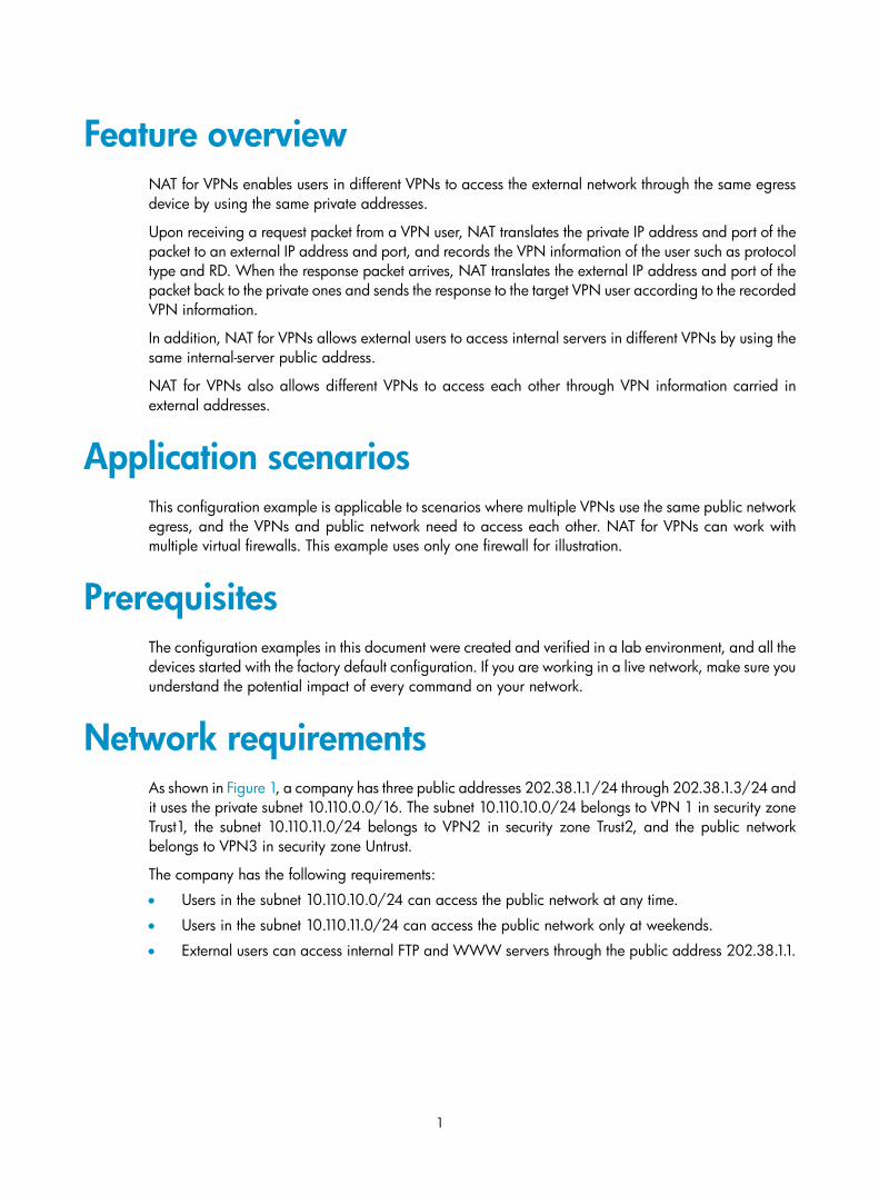
Feature overview NAT for VPNs enables users in different VPNs to access the external network through the same egress device by using the same private addresses.
Upon receiving a request packet from a VPN user, NAT translates the private IP address and port of the packet to an external IP address and port, and records the VPN information of the user such as protocol type and RD. When the response packet arrives, NAT translates the external IP address and port of the packet back to the private ones and sends the response to the target VPN user according to the recorded VPN information.
In addition, NAT for VPNs allows external users to access internal servers in different VPNs by using the same internal-server public address.
NAT for VPNs also allows different VPNs to access each other through VPN information carried in external addresses.
Application scenarios This configuration example is applicable to scenarios where multiple VPNs use the same public network egress, and the VPNs and public network need to access each other. NAT for VPNs can work with multiple virtual firewalls. This example uses only one firewall for illustration.
Prerequisites The configuration examples in this document were created and verified in a lab environment, and all the devices started with the factory default configuration. If you are working in a live network, make sure you understand the potential impact of every command on your network.
Network requirements As shown in Figure 1, a company has three public addresses 202.38.1.1/24 through 202.38.1.3/24 and it uses the private subnet 10.110.0.0/16. The subnet 10.110.10.0/24 belongs to VPN 1 in security zone Trust1, the subnet 10.110.11.0/24 belongs to VPN2 in security zone Trust2, and the public network belongs to VPN3 in security zone Untrust.
The company has the following requirements:
• Users in the subnet 10.110.10.0/24 can access the public network at any time.
• Users in the subnet 10.110.11.0/24 can access the public network only at weekends.
• External users can access internal FTP and WWW servers through the public address 202.38.1.1.
2
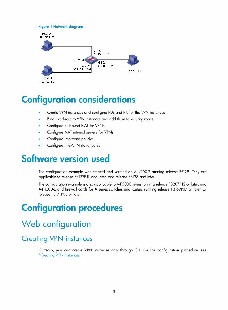
Figure 1 Network diagram
Configuration considerations • Create VPN instances and configure RDs and RTs for the VPN instances
• Bind interfaces to VPN instances and add them to security zones
• Configure outbound NAT for VPNs
• Configure NAT internal servers for VPNs
• Configure inter-zone policies
• Configure inter-VPN static routes
Software version used The configuration example was created and verified on A-U200-S running release F5128. They are applicable to release F5123P11 and later, and release F5128 and later.
The configuration example is also applicable to A-F5000 series running release F3207P12 or later, and A-F1000-E and firewall cards for A series switches and routers running release F3169P07 or later, or release F3171P03 or later.
Configuration procedures
Web configuration
Creating VPN instances Currently, you can create VPN instances only through CLI. For the configuration procedure, see "Creating VPN instances."
3
Binding interfaces to VPN instances and adding them to security zones Binding interfaces to VPN instances
Currently, you can bind interfaces to VPN instances only through CLI. For the configuration procedure, see Binding interfaces to VPN instances and adding them to security zones.
Adding interfaces to security zones
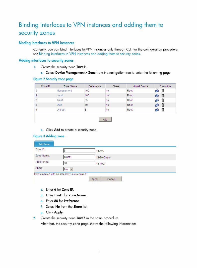
1. Create the security zone Trust1:
a. Select Device Management > Zone from the navigation tree to enter the following page:
Figure 2 Security zone page
b. Click Add to create a security zone.
Figure 3 Adding zone
c. Enter 6 for Zone ID.
d. Enter Trust1 for Zone Name.
e. Enter 80 for Preference.
f. Select No from the Share list.
g. Click Apply.
2. Create the security zone Trust2 in the same procedure.
After that, the security zone page shows the following information:
4
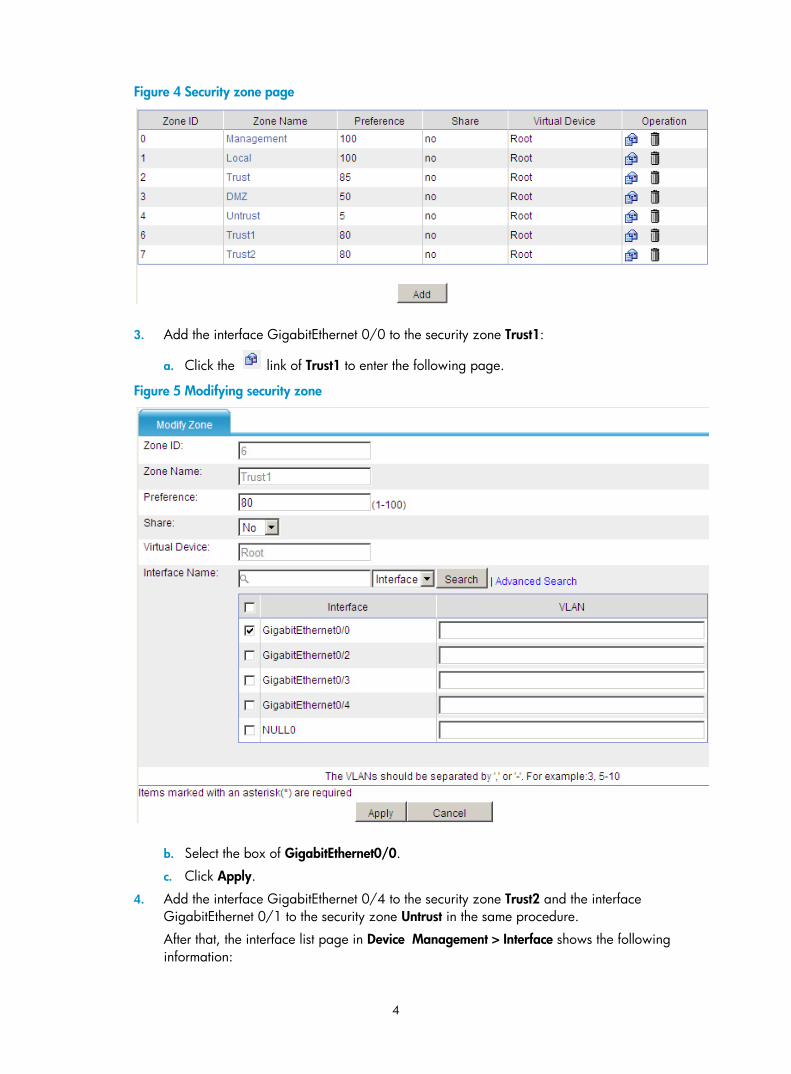
Figure 4 Security zone page
3. Add the interface GigabitEthernet 0/0 to the security zone Trust1:
a. Click the link of Trust1 to enter the following page.
Figure 5 Modifying security zone
b. Select the box of GigabitEthernet0/0.
c. Click Apply.
4. Add the interface GigabitEthernet 0/4 to the security zone Trust2 and the interface GigabitEthernet 0/1 to the security zone Untrust in the same procedure.
After that, the interface list page in Device Management > Interface shows the following information:
5
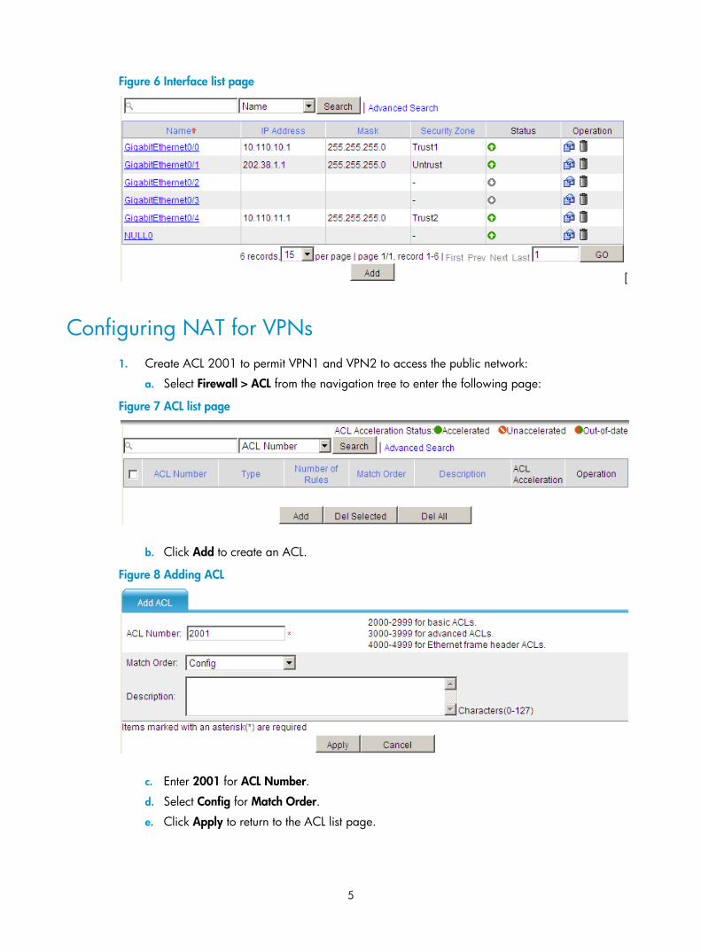
Figure 6 Interface list page
[
Configuring NAT for VPNs 1. Create ACL 2001 to permit VPN1 and VPN2 to access the public network:
a. Select Firewall > ACL from the navigation tree to enter the following page:
Figure 7 ACL list page
b. Click Add to create an ACL.
Figure 8 Adding ACL
c. Enter 2001 for ACL Number.
d. Select Config for Match Order.
e. Click Apply to return to the ACL list page.

6
Figure 9 ACL list page
f. Click the link of ACL 2001 to add rules.
Figure 10 Basic ACL 2001 page
g. Click Add to enter the following page:
Figure 11 Adding rule
h. Select the box of Source IP Address, enter 10.110.10.0 for it, enter 0.0.0.255 for Source Wildcard, select VPN1 for VPN Instance, and click Apply to return to the Basic ACL 2001 page.
Figure 12 Basic ACL 2001 page
i. Click Add.
7
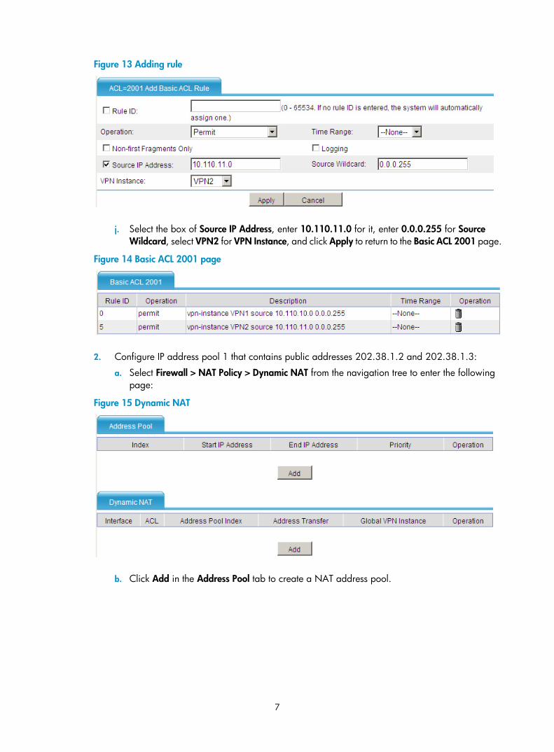
Figure 13 Adding rule
j. Select the box of Source IP Address, enter 10.110.11.0 for it, enter 0.0.0.255 for Source Wildcard, select VPN2 for VPN Instance, and click Apply to return to the Basic ACL 2001 page.
Figure 14 Basic ACL 2001 page
2. Configure IP address pool 1 that contains public addresses 202.38.1.2 and 202.38.1.3:
a. Select Firewall > NAT Policy > Dynamic NAT from the navigation tree to enter the following page:
Figure 15 Dynamic NAT
b. Click Add in the Address Pool tab to create a NAT address pool.
8
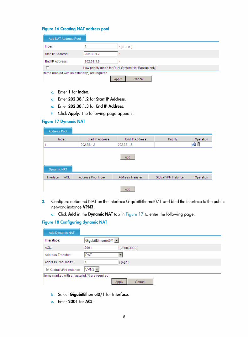
Figure 16 Creating NAT address pool
c. Enter 1 for Index.
d. Enter 202.38.1.2 for Start IP Address.
e. Enter 202.38.1.3 for End IP Address.
f. Click Apply. The following page appears:
Figure 17 Dynamic NAT
3. Configure outbound NAT on the interface GigabitEthernet0/1 and bind the interface to the public network instance VPN3:
a. Click Add in the Dynamic NAT tab in Figure 17 to enter the following page:
Figure 18 Configuring dynamic NAT
b. Select GigabitEthernet0/1 for Interface.
c. Enter 2001 for ACL.
9
d. Select PAT for Address Transfer.
e. Enter 1 for Address Pool Index.
f. Select the box of Global VPN Instance, and select VPN3.
g. Click Apply.
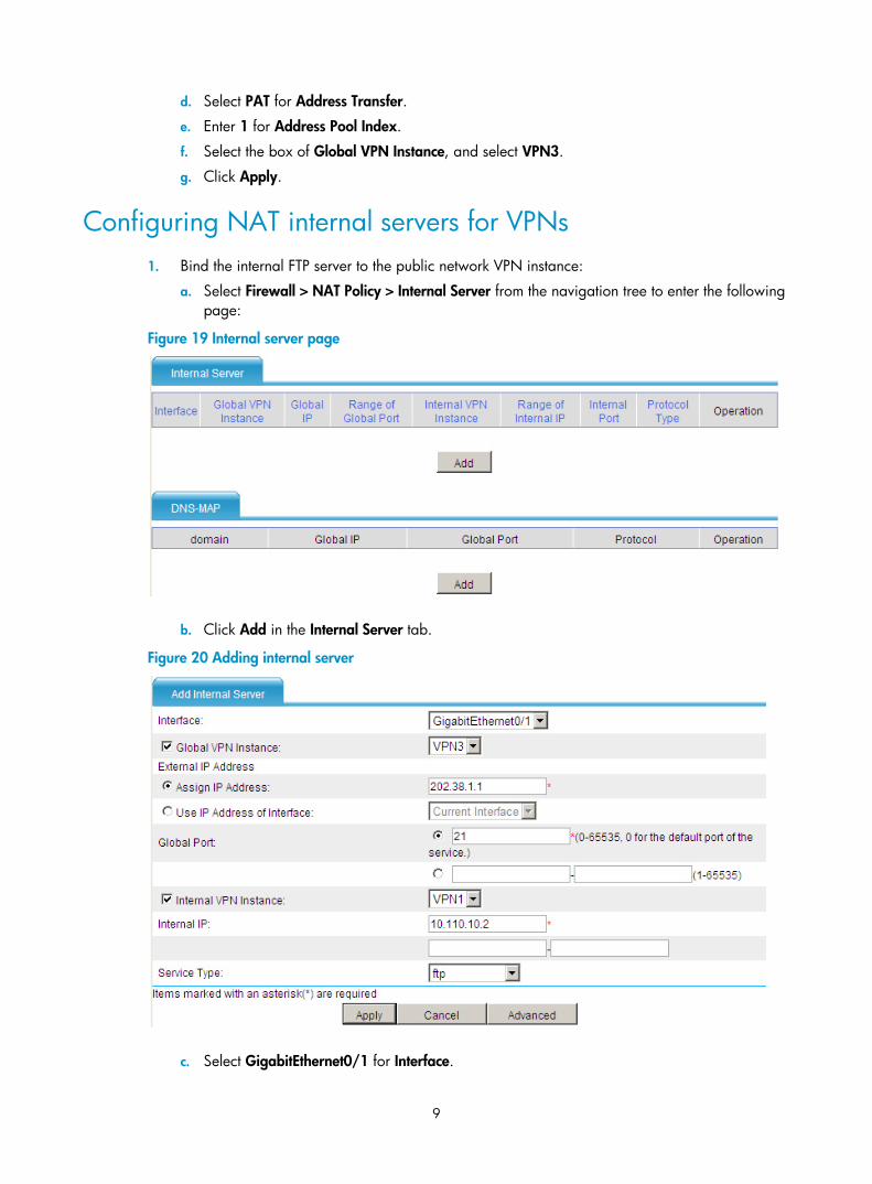
Configuring NAT internal servers for VPNs 1. Bind the internal FTP server to the public network VPN instance:
a. Select Firewall > NAT Policy > Internal Server from the navigation tree to enter the following page:
Figure 19 Internal server page
b. Click Add in the Internal Server tab.
Figure 20 Adding internal server
c. Select GigabitEthernet0/1 for Interface.

10
d. Select the box of Global VPN Instance and select VPN3 for it.
e. Select the radio button of Assign IP Address and enter 202.38.1.1.
f. Enter 21 for Global Port.
g. Select the box of Internal VPN Instance and select VPN1 for it.
h. Enter 10.110.10.2 for Internal IP.
i. Select ftp for Service Type.
j. Click Apply. The following page appears:
Figure 21 Internal server page
2. Bind the internal WWW server to the public network VPN instance:
a. Click Add in Figure 21 to enter the following page:
Figure 22 Adding internal server
b. Select GigabitEthernet0/1 for Interface.
c. Select the box of Global VPN Instance and select VPN3 for it.
d. Select the radio button of Assign IP Address and enter 202.38.1.1.
e. Enter 80 for Global Port.
f. Select the box of Internal VPN Instance and select VPN2 for it.
g. Enter 10.110.11.2 for Internal IP.
h. Select www for Service Type.
11
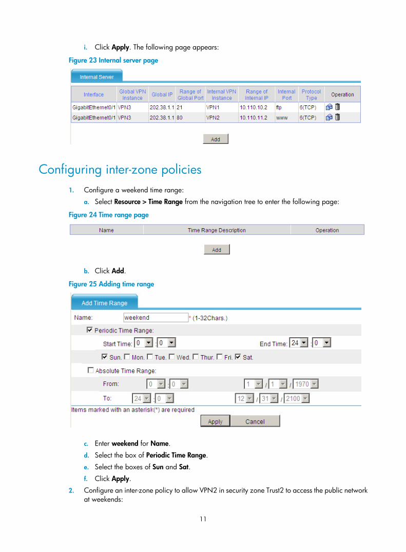
i. Click Apply. The following page appears:
Figure 23 Internal server page
Configuring inter-zone policies 1. Configure a weekend time range:
a. Select Resource > Time Range from the navigation tree to enter the following page:
Figure 24 Time range page
b. Click Add.
Figure 25 Adding time range
c. Enter weekend for Name.
d. Select the box of Periodic Time Range.
e. Select the boxes of Sun and Sat.
f. Click Apply.
2. Configure an inter-zone policy to allow VPN2 in security zone Trust2 to access the public network at weekends:
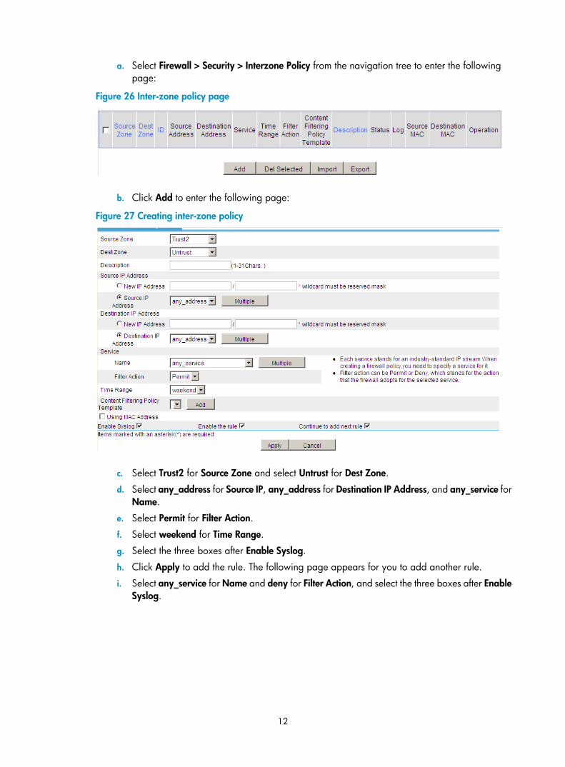
12
a. Select Firewall > Security > Interzone Policy from the navigation tree to enter the following page:
Figure 26 Inter-zone policy page
b. Click Add to enter the following page:
Figure 27 Creating inter-zone policy
c. Select Trust2 for Source Zone and select Untrust for Dest Zone.
d. Select any_address for Source IP, any_address for Destination IP Address, and any_service for Name.
e. Select Permit for Filter Action.
f. Select weekend for Time Range.
g. Select the three boxes after Enable Syslog.
h. Click Apply to add the rule. The following page appears for you to add another rule.
i. Select any_service for Name and deny for Filter Action, and select the three boxes after Enable Syslog.
13
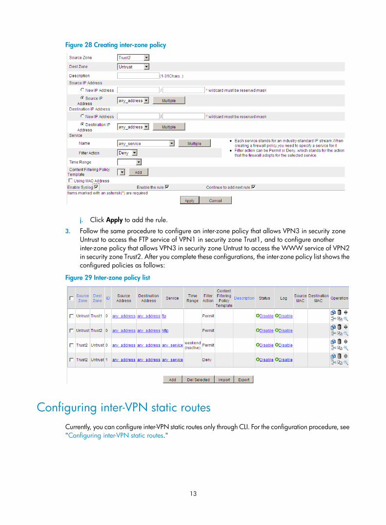
Figure 28 Creating inter-zone policy
j. Click Apply to add the rule.
3. Follow the same procedure to configure an inter-zone policy that allows VPN3 in security zone Untrust to access the FTP service of VPN1 in security zone Trust1, and to configure another inter-zone policy that allows VPN3 in security zone Untrust to access the WWW service of VPN2 in security zone Trust2. After you complete these configurations, the inter-zone policy list shows the configured policies as follows:
Figure 29 Inter-zone policy list
Configuring inter-VPN static routes Currently, you can configure inter-VPN static routes only through CLI. For the configuration procedure, see "Configuring inter-VPN static routes."
14
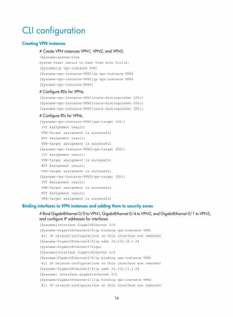
CLI configuration Creating VPN instances
# Create VPN instances VPN1, VPN2, and VPN3. <Sysname>system-view
System View: return to User View with Ctrl+Z.
[Sysname]ip vpn-instance VPN1
[Sysname-vpn-instance-VPN1]ip vpn-instance VPN2
[Sysname-vpn-instance-VPN2]ip vpn-instance VPN3
[Sysname-vpn-instance-VPN3]
# Configure RDs for VPNs. [Sysname-vpn-instance-VPN1]route-distinguisher 100:1
[Sysname-vpn-instance-VPN2]route-distinguisher 200:1
[Sysname-vpn-instance-VPN3]route-distinguisher 300:1
# Configure RTs for VPNs. [Sysname-vpn-instance-VPN1]vpn-target 100:1
IVT Assignment result:
VPN-Target assignment is successful
EVT Assignment result:
VPN-Target assignment is successful
[Sysname-vpn-instance-VPN2]vpn-target 200:1
IVT Assignment result:
VPN-Target assignment is successful
EVT Assignment result:
VPN-Target assignment is successful
[Sysname-vpn-instance-VPN3]vpn-target 300:1
IVT Assignment result:
VPN-Target assignment is successful
EVT Assignment result:
VPN-Target assignment is successful
Binding interfaces to VPN instances and adding them to security zones
# Bind GigabitEthernet 0/0 to VPN1, GigabitEthernet 0/4 to VPN2, and GigabitEthernet 0/1 to VPN3, and configure IP addresses for interfaces. [Sysname]interface GigabitEthernet 0/4
[Sysname-GigabitEthernet0/0]ip binding vpn-instance VPN1
All IP related configurations on this interface are removed!
[Sysname-GigabitEthernet0/0]ip addr 10.110.10.1 24
[Sysname-GigabitEthernet0/0]qui
[Sysname]interface GigabitEthernet 0/4
[Sysname-GigabitEthernet0/4]ip binding vpn-instance VPN2
All IP related configurations on this interface are removed!
[Sysname-GigabitEthernet0/4]ip addr 10.110.11.1 24
[Sysname] interface gigabitethernet 0/1
[Sysname-GigabitEthernet0/1]ip binding vpn-instance VPN3
All IP related configurations on this interface are removed!
15
[Sysname-GigabitEthernet0/1]ip addr 202.38.1.1 24
# Create security zones Trust1 and Trust2, and add GigabitEthernet 0/0 to Trust1, GigabitEthernet 0/4 to Trust2, and GigabitEthernet 0/1 to Untrust. [Sysname]zone name Trust1 id 6
[Sysname-zone-Trust1]priority 80
[Sysname-zone-Trust1]import interface GigabitEthernet 0/0
[Sysname]zone name Trust2 id 7
[Sysname-zone-Trust2]priority 80
[Sysname-zone-Trust2]import interface GigabitEthernet 0/4
[Sysname]zone name Untrust
[Sysname-zone-Untrust]import interface GigabitEthernet 0/1
NOTE:
Currently, only some releases support security zone configuration through CLI. If you release does not support this configuration, configure security zones through Web. For the configuration procedure, see Web configuration.
Configure NAT for VPNs
# Configure NAT address pool 1 that contains public addresses 202.38.1.2 and 202.38.1.3. <Sysname> system-view
[Sysname] nat address-group 1 202.38.1.2 202.38.1.3
# Configure ACL 2001 to permit the addresses of VPN1 and VPN2. [Sysname] acl number 2001
[Sysname-acl-basic-2001]rule 0 permit vpn-instance VPN1 source 10.110.10.0 0.0.0.255
[Sysname-acl-basic-2001]rule 5 permit vpn-instance VPN2 source 10.110.11.0 0.0.0.255
[Sysname-acl-basic-2001] rule deny
# Configure outbound NAT on GigabitEthernet0/1 to allow VPN1 and VPN3 to access the public network VPN3. [Sysname] interface gigabitethernet 0/1
[Sysname-GigabitEthernet0/1] nat outbound 2001 address-group 1 vpn-instance VPN3
[Sysname-GigabitEthernet0/1] quit
Configuring NAT internal servers for VPNs
# Enter the view of GigabitEthernet0/1. <Sysname> system-view
[Sysname] interface gigabitethernet 0/1
# Configure the internal FTP server and associate it with the public network VPN3. [Sysname-GigabitEthernet0/1]nat server protocol tcp global 202.38.1.1 ftp vpn-instance VPN3 inside 10.110.10.2 ftp
# Configure the internal WWW server and associate it with the public network VPN3. [Sysname-GigabitEthernet0/1]nat server protocol tcp global 202.38.1.1 www vpn-instance VPN3 inside 10.110.11.2 www
[Sysname-GigabitEthernet0/1] quit
Configuring inter-zone policies
# Configure a weekend time range. [Sysname]time-range weekend 00:00 to 24:00 off-day
16
# Configure an inter-zone policy to allow VPN2 in security zone Trust2 to access the public network only at weekends and to record log information. [Sysname]switchto vd Root
[Sysname]interzone source Trust2 destination Untrust
[Sysname-interzone-Trust2-Untrust] rule 0 permit logging time-range weekend
[Sysname-interzone-Trust2-Untrust-rule-0]source-ip any_address
[Sysname-interzone-Trust2-Untrust-rule-0]destination-ip any_address
[Sysname-interzone-Trust2-Untrust-rule-0]service any_service
[Sysname-interzone-Trust2-Untrust-rule-0]rule enable
[Sysname-interzone-Trust2-Untrust-rule-0] rule 1 deny logging
[Sysname-interzone-Trust2-Untrust-rule-1]source-ip any_address
[Sysname-interzone-Trust2-Untrust-rule-1]destination-ip any_address
[Sysname-interzone-Trust2-Untrust-rule-1]service any_service
[Sysname-interzone-Trust2-Untrust-rule-1]rule enable
# Configure an inter-zone policy to allow VPN3 in security zone Untrust to access the FTP service of VPN1 in security zone Trust1 and to access the WWW service of VPN2 in security zone Trust2. [Sysname]interzone source Untrust destination Trust1
[Sysname-interzone-Untrust-Trust1]rule 0 permit logging
[Sysname-interzone-Untrust-Trust1-rule-0]source-ip any_address
[Sysname-interzone-Untrust-Trust1-rule-0]destination-ip any_address
[Sysname-interzone-Untrust-Trust1-rule-0]service ftp
[Sysname-interzone-Untrust-Trust1-rule-0]rule enable
[Sysname-interzone-Untrust-Trust1-rule-0]interzone source Untrust destination Trust2
[Sysname-interzone-Untrust-Trust2]rule 0 permit logging
[Sysname-interzone-Untrust-Trust2-rule-0]source-ip any_address
[Sysname-interzone-Untrust-Trust2-rule-0]destination-ip any_address
[Sysname-interzone-Untrust-Trust2-rule-0]service http
[Sysname-interzone-Untrust-Trust2-rule-0]rule enable
NOTE:
Currently, only some releases support inter-zone policy configuration through CLI. If you release does notsupport this configuration, configure inter-zone policies through Web. For the configuration procedure, see Web configuration.
Configuring inter-VPN static routes
# Configure a static route from VPN1 to VPN3. [Sysname]ip route-static vpn-instance VPN1 0.0.0.0 0.0.0.0 vpn-instance VPN3 202.38.
1.11
# Configure a static route from VPN2 to VPN3. [Sysname]ip route-static vpn-instance VPN2 0.0.0.0 0.0.0.0 vpn-instance VPN3 202.38.
1.11
Verifying the configuration Access Host C from Host A during working hours. The operation succeeds.
# The following shows the session information:
17
Initiator:
Source IP/Port : 10.110.10.2/2048
Dest IP/Port : 202.38.1.11/1280
VPN-Instance/VLAN ID/VLL ID: VPN1
Responder:
Source IP/Port : 202.38.1.11/0
Dest IP/Port : 202.38.1.3/1026
VPN-Instance/VLAN ID/VLL ID: VPN3
Pro: ICMP(1) App: unknown State: ICMP-CLOSED
Start time: 2012-03-07 17:42:41 TTL: 24s
Root Zone(in): trust1
Zone(out): Untrust
Received packet(s)(Init): 1 packet(s) 60 byte(s)
Received packet(s)(Reply): 1 packet(s) 60 byte(s)
Access Host C from Host B during working hours. The operation fails.
# The following shows the inter-zone policy log information: %Mar 8 08:46:23:116 2012 H3C FILTER/6/ZONE_DP_FLT_EXECUTION_ICMP_LOG: srcZoneNa
me(1034)=Trust2;destZoneName(1035)=Untrust;rule_ID(1070)=1;policyActType(1071)=d
enied;protType(1001)=ICMP(1);srcIPAddr(1017)=10.110.11.2;destIPAddr(1019)=202.38
.1.11;icmpType(1072)=(114)echo(8);icmpCode(1073)=(142)unrecognized code(0);begin
Time_e(1013)=03082012084612;endTime_e(1014)=03082012084612;
Access Host C from Host B at weekends. The operation succeeds.
# The following shows the inter-zone policy log information: %Mar 10 08:51:17:117 2012 H3C FILTER/6/ZONE_DP_FLT_EXECUTION_ICMP_LOG: srcZoneNa
me(1034)=Trust2;destZoneName(1035)=Untrust;rule_ID(1070)=0;policyActType(1071)=p
ermitted;protType(1001)=ICMP(1);srcIPAddr(1017)=10.110.11.2;destIPAddr(1019)=202
.38.1.11;icmpType(1072)=(114)echo(8);icmpCode(1073)=(142)unrecognized code(0);be
ginTime_e(1013)=03102012085043;endTime_e(1014)=03102012085115;
# The following shows the session information: Initiator:
Source IP/Port : 10.110.11.2/2048
Dest IP/Port : 202.38.1.11/512
VPN-Instance/VLAN ID/VLL ID: VPN2
Responder:
Source IP/Port : 202.38.1.11/0
Dest IP/Port : 202.38.1.3/1027
VPN-Instance/VLAN ID/VLL ID: VPN3
Pro: ICMP(1) App: unknown State: ICMP-CLOSED
Start time: 2012-03-10 09:10:14 TTL: 20s
Root Zone(in): Trust2
Zone(out): Untrust
Received packet(s)(Init): 1 packet(s) 60 byte(s)
Received packet(s)(Reply): 1 packet(s) 60 byte(s)
Access the FTP server at 202.38.1.1 on Host A from Host C. The operation succeeds.
# The following shows the inter-zone policy log information: %Mar 10 09:15:29:218 2012 H3C FILTER/6/ZONE_DP_FLT_EXECUTION_TCP_LOG: srcZoneNam
18
e(1034)=Untrust;destZoneName(1035)=Trust1;rule_ID(1070)=0;policyActType(1071)=pe
rmitted;protType(1001)=TCP(6);srcIPAddr(1017)=202.38.1.11;destIPAddr(1019)=10.11
0.10.2;srcPortNum(1018)=2116;destPortNum(1020)=21;beginTime_e(1013)=031020120913
26;endTime_e(1014)=03102012091514;
# The following shows the session information: Initiator:
Source IP/Port : 10.110.10.2/20
Dest IP/Port : 202.38.1.11/2117
VPN-Instance/VLAN ID/VLL ID: VPN1
Responder:
Source IP/Port : 202.38.1.11/2117
Dest IP/Port : 202.38.1.1/20
VPN-Instance/VLAN ID/VLL ID: VPN3
Pro: TCP(6) App: FTP-data State: TCP-EST
Start time: 2012-03-10 09:13:27 TTL: 3594s
Root Zone(in): Trust1
Zone(out): Untrust
Received packet(s)(Init): 2 packet(s) 88 byte(s)
Received packet(s)(Reply): 1 packet(s) 48 byte(s)
Initiator:
Source IP/Port : 202.38.1.11/2116
Dest IP/Port : 202.38.1.1/21
VPN-Instance/VLAN ID/VLL ID: VPN3
Responder:
Source IP/Port : 10.110.10.2/21
Dest IP/Port : 202.38.1.11/2116
VPN-Instance/VLAN ID/VLL ID: VPN1
Pro: TCP(6) App: FTP State: TCP-EST
Start time: 2012-03-10 09:13:26 TTL: 3594s
Root Zone(in): Untrust
Zone(out): Trust1
Received packet(s)(Init): 12 packet(s) 585 byte(s)
Received packet(s)(Reply): 11 packet(s) 805 byte(s)
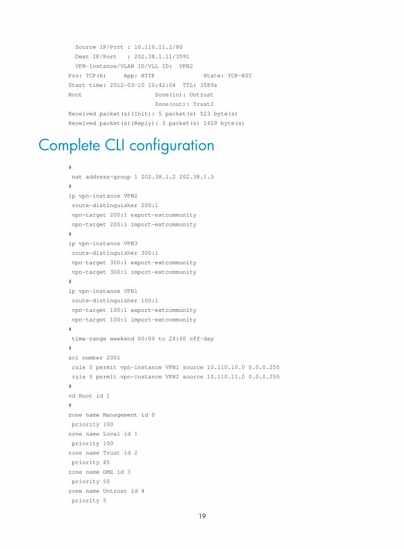
Access the WWW server at 202.38.1.1 on Host B from Host C. The operation succeeds.
# The following shows the inter-zone policy log information: %Mar 10 10:43:11:221 2012 H3C FILTER/6/ZONE_DP_FLT_EXECUTION_TCP_LOG: srcZoneNam
e(1034)=Untrust;destZoneName(1035)=Trust2;rule_ID(1070)=0;policyActType(1071)=pe
rmitted;protType(1001)=TCP(6);srcIPAddr(1017)=202.38.1.11;destIPAddr(1019)=10.11
0.11.2;srcPortNum(1018)=3591;destPortNum(1020)=80;beginTime_e(1013)=031020121043
07;endTime_e(1014)=03102012104310;
# The following shows the session information: Initiator:
Source IP/Port : 202.38.1.11/3591
Dest IP/Port : 202.38.1.1/80
VPN-Instance/VLAN ID/VLL ID: VPN3
Responder:
19
Source IP/Port : 10.110.11.2/80
Dest IP/Port : 202.38.1.11/3591
VPN-Instance/VLAN ID/VLL ID: VPN2
Pro: TCP(6) App: HTTP State: TCP-EST
Start time: 2012-03-10 10:42:04 TTL: 3589s
Root Zone(in): Untrust
Zone(out): Trust2
Received packet(s)(Init): 5 packet(s) 523 byte(s)
Received packet(s)(Reply): 3 packet(s) 1459 byte(s)
Complete CLI configuration #
nat address-group 1 202.38.1.2 202.38.1.3
#
ip vpn-instance VPN2
route-distinguisher 200:1
vpn-target 200:1 export-extcommunity
vpn-target 200:1 import-extcommunity
#
ip vpn-instance VPN3
route-distinguisher 300:1
vpn-target 300:1 export-extcommunity
vpn-target 300:1 import-extcommunity
#
ip vpn-instance VPN1
route-distinguisher 100:1
vpn-target 100:1 export-extcommunity
vpn-target 100:1 import-extcommunity
#
time-range weekend 00:00 to 24:00 off-day
#
acl number 2001
rule 0 permit vpn-instance VPN1 source 10.110.10.0 0.0.0.255
rule 5 permit vpn-instance VPN2 source 10.110.11.0 0.0.0.255
#
vd Root id 1
#
zone name Management id 0
priority 100
zone name Local id 1
priority 100
zone name Trust id 2
priority 85
zone name DMZ id 3
priority 50
zone name Untrust id 4
priority 5

20
import interface GigabitEthernet0/1
zone name Trust1 id 6
priority 80
import interface GigabitEthernet0/0
zone name Trust2 id 7
priority 80
import interface GigabitEthernet0/4
switchto vd Root
zone name Management id 0
ip virtual-reassembly
zone name Local id 1
ip virtual-reassembly
zone name Trust id 2
ip virtual-reassembly
zone name DMZ id 3
ip virtual-reassembly
zone name Untrust id 4
ip virtual-reassembly
zone name Trust1 id 6
ip virtual-reassembly
zone name Trust2 id 7
ip virtual-reassembly
interzone source Untrust destination Trust1
rule 0 permit logging
source-ip any_address
destination-ip any_address
service ftp
rule enable
interzone source Untrust destination Trust2
rule 0 permit logging
source-ip any_address
destination-ip any_address
service http
rule enable
interzone source Trust2 destination Untrust
rule 0 permit logging time-range weekend
source-ip any_address
destination-ip any_address
service any_service
rule enable
rule 1 deny logging
source-ip any_address
destination-ip any_address
service any_service
rule enable
#
local-user admin
password cipher $c$3$ljMZZW9512URK5THPwboqYoOCwnduvrv
21
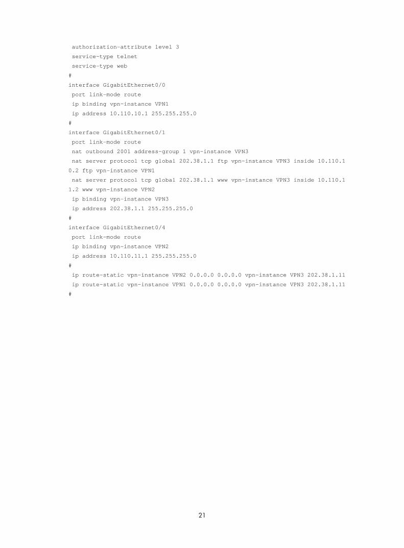
authorization-attribute level 3
service-type telnet
service-type web
#
interface GigabitEthernet0/0
port link-mode route
ip binding vpn-instance VPN1
ip address 10.110.10.1 255.255.255.0
#
interface GigabitEthernet0/1
port link-mode route
nat outbound 2001 address-group 1 vpn-instance VPN3
nat server protocol tcp global 202.38.1.1 ftp vpn-instance VPN3 inside 10.110.1
0.2 ftp vpn-instance VPN1
nat server protocol tcp global 202.38.1.1 www vpn-instance VPN3 inside 10.110.1
1.2 www vpn-instance VPN2
ip binding vpn-instance VPN3
ip address 202.38.1.1 255.255.255.0
#
interface GigabitEthernet0/4
port link-mode route
ip binding vpn-instance VPN2
ip address 10.110.11.1 255.255.255.0
#
ip route-static vpn-instance VPN2 0.0.0.0 0.0.0.0 vpn-instance VPN3 202.38.1.11
ip route-static vpn-instance VPN1 0.0.0.0 0.0.0.0 vpn-instance VPN3 202.38.1.11
#