Embed Size (px)
Citation preview

ArchitecturalHydronic Wall Fin
FIN-PRC004-ENOctober 2001

© 2001 American Standard Inc. All rights reserved. FIN-PRC004-EN
A Complete Line of Wall FinTrane architectural wall fin is ideal forheating modern commercial,institutional or industrial buildings.Attractive styling and wide applicationflexibility allow wall fin cabinet designsto be used for virtually any application.Available for hydronic or steam heating,Trane wall fin can also be used incombination with convectors for smallerareas, allowing for the use of one sourcewhen designing a radiation heatingsystem. (See FIN-DS-2 for convectorapplications.)
An effective heating system for any office. Attractive styling that blends with anyarchitectural design.
Trane Wall Fin — Simply the BestWall fin effectively meets the heatingneeds of long, open areas. It counterscold air downdrafts common toexpansive glass areas used in many oftoday’s most prestigious buildings.• Provides continuous heat along room
perimeter.• Allows removal of any unit panel for
service accessibility.• The front panel never touches the wall
— only Trane’s exclusive mountingstrip.
• The front panel can be raised orremoved without disturbing the unit ordamaging wallpaper, paint or theplaster seal.
• Operates quietly because there are nomoving parts.
• Controls with the damper or valveindividually.
• Blends well with any decor.• Works effectively with cooling-only
VAV and heat recovery systems.• Includes 14 or 16-gauge front panels.• Unit vent draft barrier enclosures.• Pipe enclosures for use with ForceFlo
and Fan Coil Units.
Wall FinI=B=R Certified Ratings for Trane WallFinThe I=B=R symbol is the registeredtrademark of the Hydronics Institutewhich tests and rates in strict accordancewith published standard wall finelements and elements with enclosures.The wall fin heating units must conform
to appropriate test standards to havecertified I=B=R ratings.
Why Hydronics?Besides the reliability of equipmentratings, and the well establishedreliability of hydronic accessories, thereare many good reasons why hydronicsystems have long been recognized asthe standard method for providingindoor comfort.
Hydronic heating, whether steam or hotwater, provides positive, controlledcirculation of the heating medium.Systems are basically self-balancing, andin larger, more complicated heatingsystems, balancing is positivelycontrolled by familiar valves andthermostats.
The life of some hydronic equipmentmay be measured in decades; someexisting boilers are more than fifty yearsold. In addition to the high efficiency ofboilers (some over 85%) the lossesthrough the distribution system areextremely low on modern installations.
Temperature control is close to ideal withhydronics. Any well-designed systemcan provide excellent comfort, withoutdrafts or sharp swings in temperature.
The flexibility of hydronic installationspermits a variety of pipingarrangements, simple or sophisticatedcontrols, and a large choice of roomdistribution units for all comfortapplications.
Type TType TA
Type FType S
Featuresand Benefits

3
Contents
FIN-PRC004-EN
Architecural Wall Fin
Features and Benefits
Application Considerations
Selection Procedure
Performance Data
Dimensional Data
Options
Mechanical Specifications
Security Wall Fin
Features and Benefits
Accessories
Model Number Description
Performance and General Data
Dimensional Data
Mechanical Specifications
Hydronic Light CommercialSlope Top Wall Fin — Model 11S
Features and Benefits
Performance and General Data
Dimensional Data
Cover and Accessory Layout
Mechanical Specifications
74
75
76
77
85
91
2
6
7
14
41
54
56
93
96
98
100
101

FIN-PRC004-EN4
Features andBenefits
A simple installation designed to lastwithout visible fasteners — Trane’sexclusively designed mounting stripmakes it possible.
Mounting strip keys entireinstallation, attaches to anywall, and assures the tightestfit possible — even againstthe most imperfect wall.
Cabinetenclosuresandaccessorypanelshinge-lockeasily intomountingstrip.
Roll-formedindentationruns fulllength ofmountingstrip foreasy boltholelocation.
Ribbed steelenclosurebracketsprovideelementsupport baseand brace the
End PanelElement/pipesupportsposition in slotsin the enclosurebracket to allowtwo-tierelement andpipeinstallation.
Cradle and nylon cradleguides assure exact elementlocation and allow elementcradles to slide freely andnoiselessly.
Curved rectangularmetal washers toassure tight fit againstthe wall.
Serves as wallpanel stop.
Serves as plasterstop for semi-recessedinstallations.
Roll-formed front panels hingeinvisibly into the mounting strip.
Rigid element damperprovides heatmodulation.
Locking clip slides over panel lip to hold itsecurely to bracket.
Panel clip and slide bolt fastener for frontpanel alignment are hidden from view.
Deluxe unit with extruded grille. The grille isseparate and hinges into the mounting strip.

5FIN-PRC004-EN
Features andBenefits
Hydronic Heating Elements — Copper/Aluminum and SteelCopper-Aluminum Elements 3/4”, 1” and 1 1/4” (19 mm, 25 mm and 32mm) Copper Tubes With 40, 50 or 58Aluminum Fins per foot (131, 164 190per meter).
Positive Temperature Control
• Efficient element-mounted damper.• Reduces unit capacity by 70 percent.• Has jam-proof bead chain control
system.• Control knob is mounted on the outlet
grille.
1 1/4” (32 mm)
3/4” (19 mm)
1” (25 mm)
Steel Elements — Standard optionsfeature 1 1/4” (32 mm) steel tube with 52steel fins per foot (171 per meter).
• Elements available in copper-aluminum or steel.
• Elements are efficient and long lasting.• Element tubes mechanically expanded
into fin collars.• Fin collars provide even and positive
spacing for even air distribution.• The mechanical bond assures an
efficient and durable elementassembly.
• Fins cannot work loose.
For Models S, F, T & TA
1 1/4” (32 mm)

FIN-PRC004-EN6
ApplicationConsiderations
A Heating System and Style to Suit Any ApplicationWall Mounted
Front Outlet Slope TopOutlet
Top Outlet
F S T TA
Top OutletWith
ExtrudedGrille
Type E Type X
Enclosure styles meet the heating needsof long, open areas in any interior.• Wall-mounted wall fin enclosures
available in depths of four and sixinches (102 mm, 152 mm).
• Enclosure depth is determined by thetype of element to be used.
• See pages 13 through 43 and Tables PD-1 through PD-25 for details.• Front inlet grilles.• Bottom inlet grilles.• Inverted enclosures for styles S, F and
T enclosures only.• Tamperproof fastener option.• Pipe Enclosures
Wall Mounted Cabinet Options
4 1/2”(114 mm)
ContinuousSheet Metal
Angle
3 3/8”(86 mm)
Pipe EnclosureBottom Inlet Grille Inverted EnclosureFront Inlet Grille
TamperproofFastener
Ceiling MountedType CS
1/2” (13 mm) Dia. Mtg. Hole
• Ceiling-mounted wall fin enclosuresavailable in depths of four and sixinches (102 and 105 mm).
• See pages 13, 14, 15 and 49.
Floor Mounted
Type E3Type E3-2W
Type E3A-1WType E3A-2W
• Pedestal wall fin enclosures availablewith one or two wide elements.
• See pages 36, 37, 42, 53, 54, 55, 56, 57and 58 and Tables PD-24, PD-25, M-1,
M-2, M-3, M-4 and M-5.

7FIN-PRC004-EN
SelectionProcedure
Hydronic/Steam Wall FinSelection
Hot Water SystemsThe capacity rating of wall fin in a hotwater heating system depends on thedifference between average watertemperature and entering airtemperature, and on the velocity atwhich water is circulated through thetube. The effect of water velocity on thecapacity rating is appreciable (see ChartS-1) and should be taken into accountwhen selecting wall fin. Following areexample selections for hot watersystems.
Hot Water Systems
Example 1Assume a two-pipe system is being usedwith 180°F average water temperature,20°F temperature drop and 65°F enteringair temperature. Assume a calculatedheat loss of 20,000 Btu, for which onerow of 1 1/4” steel element in a Type 12Senclosure is desired.
From Chart S-1, reading from 20,000 Btu(under 20°F temperature drop) across toa 1 1/4” steel element and down, indicatesa water velocity of approximately .45 ft/sec. The water velocity correction factorcorresponding to .45 ft/sec is .920. Theradiation is selected so that it woulddeliver
20,000 Btu (calculated heat loss)0.920 (velocity correction factor)
or 21,739 Btu if the water velocity were 3ft/sec. It will then deliver the required20,000 Btu at the actual water velocity of.45 ft/sec.
From Table PD-8, the output of 1 1/4”steel, Series 52 element in a Type 12Senclosure is (looking under 180°Faverage water, 65°F entering air) 1060Btu/lineal foot at 3 ft/sec water velocity.Wall fin required:21,739 Btu = 20.5 lineal feet.1060 Btu/ft
Length Selection — Loop Systems
Example 2If the unit in Example 1 above was partof a 100,000 Btu loop with a 20°F drop(across the entire loop) the watervelocity through the loop would be 2.20ft/sec and the water velocity correctionfactor for all units on this loop would beapproximately .987. For the unit beingconsidered, the radiation would beselected to deliver 20,300
20,000( .987 )Btu at 3 ft/sec water velocity.
Steam Systems — Selecting Wall FinLengthsThe capacity rating of wall fin in a steamheating system depends upon thedifference between the steamtemperature and the entering airtemperature. For any steam system, toestablish the lineal feet of wall finrequired: divide the heat loss by thecapacity rating per foot at the steamsystem and entering air conditions.
Ratings for 1 psi steam and 65°Fentering air can be found on TablesPD-1 through PD-21. Ratings for othersteam and air conditions can beobtained by multiplying the 1 psi —65°F capacity ratings by the propersteam correction factor from Table S-2.
Example 1Assume a steam system with 1 psisteam and 65°F entering air conditions.Also assume a 15,000 Btu heat loss forwhich a 1” copper-aluminum element 40fins/foot in a Type 10S enclosure isdesired.
Wall fin required:15,000 Btu = 13.9 lineal feet.1080 Btu/ft
Example 2Assume a steam system with 20 psisteam and 55°F entering air conditions.Also assume a 25,000 Btu heat loss forwhich 2 rows of 1 1/4” steel, Series 40element on 9 1/2” centers will be usedwithout a cover. The capacity rating perlineal foot from Table PD-3 at 1 psi steamand 65°F entering air is 2120 Btu/ft.Multiplying this capacity rating by 1.52(steam correction factor from Table S-2)gives a rating of 3222 Btu/ft with 20 psisteam and 55°F entering air.
Wall fin required: 25,000 Btu 3222 Btu/ft= 8 lineal feet, 2 rows high.

FIN-PRC004-EN8
SelectionProcedure
Chart S-1 — Water Velocity Correction
Factors — Pressure Drops ENGLISH
All Catalog Capacities Based On 3.0Feet Per Second Water Velocity.*
Water Velocity*Correction Factor = .04( 3 )SI

9FIN-PRC004-EN
Effect of Temperature Drop OnFin-Tube RatingsThe effect of temperature drop on heatoutput of a wall fin element can bereadily determined. Select the heatingelement using average watertemperature (entering watertemperature minus 1/2 watertemperature drop) and correct for watervelocity as follows:
SelectionProcedure
By use of the relationship,
GPM = BTU *500 x Water Temperature Drop
the waterflow rate for a wall fin unit ofthe required Btu and at a definitetemperature drop, is easily calculated.(Many engineers use gallons per minuteas the basis for selecting pipe sizes, sincecharts are set up on this basis in theASHRAE Guide. Therefore, this wouldnot be an extra step.)
The heat output of a given wall fin unitwill vary somewhat with different watervelocities, all other conditions beingequal. From Chart S-1, the water velocitycan be found for a wall fin element of theparticular tube size and gpm waterflowrequired. The velocity correction factorcan be determined by using Chart S-1.
Table S-2 — Wall Fin Rating Correction Factors*
Entering Air TemperatureSteam Press. Steam Temp. 45°F 55°F 65°F 70°F 75°F 80°F 85°F 90°F 100°F 110°F 120°F 130°F 140°F 150°FPSIG kPa (F) (c) 7°C 13°C 18C 21°C 24°C 27°C 29°C 32°C 38°C 43°C 49°C 54°C 60°C 66°C
0 0 212.0 100.0 1.19 1.09 0.97 0.92 0.87 0.82 0.77 0.70 0.63 0.54 0.46 0.38 0.31 0.25.899 6.2 215.0 101.7 1.22 1.11 1.00 0.95 0.90 0.84 0.80 0.75 0.65 0.57 0.48 0.40 0.33 0.26
5 34.5 227.1 108.4 1.34 1.22 1.11 1.05 1.00 0.95 0.90 0.81 0.75 0.66 0.57 0.49 0.41 0.3410 69.0 239.4 115.2 1.45 1.33 1.22 1.17 1.11 1.05 1.00 0.91 0.85 0.75 0.66 0.58 0.50 0.4220 137.9 258.8 126.0 1.63 1.52 1.40 1.33 1.28 1.23 1.17 1.07 1.02 0.92 0.82 0.73 0.64 0.5530 206.9 274.0 134.4 1.78 1.66 1.54 1.48 1.42 1.37 1.31 1.21 1.15 1.05 0.95 0.85 0.76 0.6840 275.8 286.7 141.5 1.91 1.79 1.66 1.61 1.54 1.49 1.43 1.32 1.27 1.16 1.06 0.97 0.87 0.7850 344.8 297.7 147.6 2.02 1.90 1.77 1.71 1.65 1.60 1.54 1.42 1.37 1.26 1.16 1.06 0.96 0.87100 689.5 337.9 169.9 2.43 2.31 2.18 2.11 2.05 2.00 1.94 1.81 1.77 1.65 1.54 1.44 1.33 1.23
*For steam pressures and air temperatures other than 1 psi and 65°F (6.895 kPa and 18.3°C). For process applications, deduct heating effect after applying above factor to 1 psi, 65°F (6.895 kPa,18.3°C air) air rating for desired element arrangement.
Table S-1 — Pipe Water Capacities and Quantities Circulated at Velocity of 3* Feet Per Second (.91 m/s)
Nominal Expanded Gals. Per Liters Per Gals./Min. @ 3’ Liters per Sec. Lbs./Hr. @ 3’ Kg/S @ .91 mPipe Size ID Linear Ft. Meter Sec. Vel.* @ .91 M/Sec. Vel. Sec. Vel.* Sel. Vel.3/4” CA (19 mm) 0.836” (21 mm) .029 .36 5.13 .324 2,555 .3221” CA (25 mm) 1.073” (27 mm) .047 .58 8.45 .533 4,215 .5311 1/4” CA (32 mm) 1.311” (33 mm) .070 .87 12.6 .795 6,285 .7921 1/4” ST (32 mm) 1.40” (36 mm) .080 .99 14.39 .908 7,170 .903*3 Ft./Sec. (.91 m/Sec) Velocity is Basis for Hot Water Rating Factors Shown in Chart S-1.Velocity Ft./Sec. = Lbs. Per Hour
(Gals. Per Ft.) (3600) (8.3)For quiet operation, a maximum of 5 ft/sec (1.5 m/Sec) velocity is recommended.

FIN-PRC004-EN10
SelectionProcedure
Table S-3 — Correction Factors for Non-Standard Average Water Temperatures
Average Entering Air TemperatureWater Temp. 45°F 50°F 55°F 60°F 65°F 70°F 75°F 80°F 85°F(F) (C) 7°C 10°C 13°C 16°C 18°C 21°C 24°C 27°C 29°C170 77 .82 .77 .72 .67 .61 .57 .53 .48 .44180 82 .91 .86 .81 .75 .69 .65 .61 .56 .52190 88 1.00 .94 .89 .84 .78 .73 .69 .64 .60200 93 1.09 1.03 .97 .92 .86 .81 .77 .72 .68210 99 1.18 1.12 1.06 1.01 .95 .90 .85 .80 .76220 104 1.27 1.21 1.15 1.09 1.05 .98 .93 .88 .84230 110 1.37 1.30 1.24 1.19 1.14 1.08 1.03 .98 .93240 116 1.47 1.41 1.35 1.29 1.25 1.17 1.12 1.07 1.02250 121 1.57 1.50 1.44 1.38 1.32 1.26 1.20 1.15 1.10260 127 1.67 1.60 1.52 1.46 1.40 1.34 1.29 1.24 1.20270 132 1.78 1.70 1.62 1.56 1.50 1.44 1.39 1.34 1.29280 138 1.88 1.80 1.72 1.66 1.60 1.54 1.48 1.43 1.38290 143 1.98 1.90 1.82 1.75 1.69 1.63 1.58 1.52 1.48300 149 2.08 2.00 1.92 1.85 1.79 1.73 1.67 1.62 1.57
NOTE: To determine capacity of non-standard conditions, multiply the corresponding factor above by the BTU (Watts/meter) steam rating found on pages 13-37.
Table S-4 — Factors Used to Convert 1 PSI
Steam Ratings to Hot Water Ratings at
Temperatures Indicated
Average Water Temperature Correction(F) (C) Factor
100°F 38°C 0.15110°F 43°C 0.20120°F 49°C 0.26130°F 54°C 0.33140°F 60°C 0.40150°F 66°C 0.45155°F 68°C 0.49160°F 71°C 0.53165°F 74°C 0.57170°F 77°C 0.61175°F 79°C 0.65180°F 82°C 0.69185°F 85°C 0.73190°F 88°C 0.78195°F 91°C 0.82200°F 93°C 0.86205°F 96°C 0.91210°F 99°C 0.95215°F 102°C 1.00220°F 104°C 1.05225°F 107°C 1.09230°F 110°C 1.14235°F 113°C 1.20240°F 116°C 1.25
Note: To determine capacity at non-standard conditions,multiply the corresponding factor above by the BTU(Watts/meter) steam rating found on pages 13-37.
*The weight of a U.S. gallon of water at60°F is 8.33 pounds. At a flow rate of1 U.S. gpm, the weight of the watercirculated through the system in onehour is 1.0 x 8.33 multiplied by 60 minute= 500 pounds.

11FIN-PRC004-EN
ExampleA 12S enclosure is to be installed 6”above the recommended installedheight. Compute the new capacity rating:
Wall Fin Correction Factors Selection
1Actual installed height is 19 7/32” (13 7/32”from Table PD-8 + 6” (152 mm) ).Interpolating from Table S-5, the heatingeffect factor is 1.065.
2Recommended installed height is 13 7/32
(from Table PD-8). From Table S-5, theheating effect is 1.075.
3Actual capacity = rated capacity(Table PD-8) x 1.065
1.075
Rating Adjustment for Greater ThanCataloged Installed Height-HeatingEffectRatings in Tables PD-1 through PD-25include the factor shown in Table S-5 forinstalled heights recommended.Installed height defines the installedlocation that is the basis for thepublished rating and determines thepercentage which may be added tocondensation capacity. If the unit isinstalled at a different height thanrecommended, the followingcomputation applies:
Capacity at actual installed height =
(Table S-5 factor foractual installed height)Rated Capacity x
(Table S-5 factor forrecom. installed height)
SelectionProcedure
Determining Pressure Drop(Refer To Chart S-1)
One-Row Units — Read pressure dropper 100 feet (30.5 m) on one rowassembly below the water velocity.
Two-Row Units, Serpentined (piped inseries) — All water passes through bothrows, so pressure drop per 100 feet (30.5m) of assembly is twice the pressuredrop below the water velocity.
Two-Row Units, Headered (piped inparallel) — Half the water flows througheach row. The actual water velocity ineach row is one-half the water velocity.The water velocity correction factorappears below the actual water velocity.Pressure drop will be the same for eachrow, so the drop per 100 (30.5 m) feet ofassembly appears below the actualwater velocity.
Table S-5 — Heating Effect Factors for Greater Than Cataloged Installed Heights
Installed Heights (Inches)19” 20” 21” 22” 23” 24” 25” 26” 27” 28” 29” 30” 32” 34” 36” or More
18” Or Less 483 508 533 559 584 610 635 660 686 711 737 762 813 864 914Type Enclosure 457 mm mm mm mm mm mm mm mm mm mm mm mm mm mm mm mmBare Element 1.15 1.14 1.13 1.12 1.11 1.10 1.09 1.08 1.07 1.06 1.05 1.04 1.03 1.02 1.01 1.00
S 1.075 1.07 1.065 1.06 1.055 1.05 1.045 1.04 1.035 1.03 1.025 1.02 1.015 1.01 1.005 1.00F 1.15 1.14 1.3 1.12 1.11 1.10 1.09 1.08 1.07 1.06 1.05 1.04 1.03 1.02 1.01 1.00
T, TA, E 1.00 1.00 1.00 1.00 1.00 1.00 1.00 1.00 1.00 1.00 1.00 1.00 1.00 1.00 1.00 1.00Installed height is vertical distance from floor to top of upper element for bare element; top of outlet grille for Type F enclosure; center of outlet grille for Type S enclosure; andunderside of the outlet grille for Type T, TA or E unit.

FIN-PRC004-EN12
SelectionProcedure
For headered two-row elementinstallations (elements piped in parallel),the maximum capacity from Table S-6 canbe doubled.
For water temperature drop other than20°F (-6.7C), the maximum capacity maybe determined as follows:
Maximum Capacity =Max. Cap. (Table S-6) x Actual Temp. Drop
20°F Temp. Drop
Maximum Installed LengthsHot water systems velocity and pressuredrop are two factors that will influencethe maximum installed lengths of wall finhot water systems. Velocity in any pipesize is dependent upon the capacity ofthe installed wall fin and the watertemperature drop through the unit. TableS-6 gives the maximum installedcapacity for any single wall fin unit orloop based on *5 ft./sec (1.5 m/sec).velocity through the tube (maximumrecommended for quiet operation) and a20°F (-6.7°C) water temperature drop.
The maximum recommended installedlength for any element and enclosurecombination can be determined bydividing the maximum recommendedcapacity from Table S-6 by the lineal footcapacity of the element and enclosurecombination from the capacity table.
Wall fin elements having the smallesttube sizes and highest velocities will givethe most efficient heat output and thelowest pipe fitting costs. However, thisshould be balanced against lowerpressure drops and perhaps a moreeconomical circulating pump selectionmade possible with large tube sizes orlarger temperature drops.
*Tables based on 3 ft/sec. (.91 m/sec.)velocity should not exceed 8 ft/sec(2.4 m/sec.) due to pipe corrosion.
Table S-6 — Hot Water Systems, Maximum Capacity*
Tube Size 1 1/4” Steel 2” Steel 1 1/4” Copper 1” Copper 3/4” CopperMaximum (32 mm) (51 mm) (32 mm) (25 mm) (19 mm)Capacity(Btu Hr.) 240,000 530,000 210,300 140,800 85,500(Watts) 70,344 155,343 61,639 41,268 25,060
*For low pressure systems. Based on 1/4 psi (1.7kPa) pressure drop per 100 feet (30.5 m).

13FIN-PRC004-EN
SelectionProcedure
Provisions For ExpansionCopper tube wall fin elements andcopper tubing, when installed at 40°F(4.4°C) and operated at 200°F (93°C)average water temperature, will expandas much as 1/8” (3.2 mm) in each 10’ (3m) length. Provisions must be made toaccommodate this expansion at theheating element supports and at theends of the wall fin elements and piping.
Packless expansion joints and flexibleconnectors are commercially availableto accommodate expansion in ahorizontal run of wall fin or at the endsof piping. Manufacturer’s literatureshould be consulted for details.
Charts S-2 and S-3 give the total amountof expansion for various lengths ofcopper or steel tube when installed at40°F (4.4°C) and operated at different hotwater or steam temperatures.
OPERATINGTEMP*
INSTALLED LENGTH (IN METERS) SI
1.5 3.1 4.6 6.1 7.6 9.1 10.7 12.2 13.7 15.2 16.8 18.3OPERATINGTEMP*
INSTALLED LENGTH (IN METERS) SI
204°C
177°C
149°C
121°C
93°C
AMOUNT OF EXPANSION (IN MILLIMETERS)
0 6 13 19 25 32 38 44
Chart S-2— Expansion in Steel Elements and Steel Pipe
OPERATINGTEMP* 5 10 15 20 25 30 35 40 45 50 55 60
400°F
350°F
300°F
250°F
200°F0 1/4 1/2 3/4 1 1 1/4 1 1/2 1 3/4
INSTALLED LENGTH (IN FEET) ENGLISH
AMOUNT OF EXPANSION (IN INCHES)
Chart S-3 — Expansion in Copper-Aluminum Elements and Copper Tube
OPERATINGTEMP* 5 10 15 20 25 30 35 40 45 50 55 60
INSTALLED LENGTH (IN FEET) ENGLISH
300°F
250°F
200°F
0 1/4 1/2 3/4 1 1 1/4 1 1/2 1 3/4AMOUNT OF EXPANSION (IN INCHES)
1.5 3.1 4.6 6.1 7.6 9.1 10.7 12.2 13.7 15.2 16.8 18.3
0 6 13 19 25 32 38 44AMOUNT OF EXPANSION (IN MILLIMETERS)
149°C
121°C
93°C
*Based on wall fin installed at 40°F (4.4°C). For wall fininstalled at other temperatures, subtract the installationtemperature from the operating temperature to find theactual temperature difference. Add this difference to40°F (4.4°C). Now read in Chart S-2 or S-3 from thetemperature obtained across to installed length anddown to the amount of expansion.

FIN-PRC004-EN14
PerformanceData
Table PD-1 — Ratings of Wall Fin Copper/Aluminum Elements Without Enclosures
Steam Capacity Hot Water CapacityPer Ft.-1 Psi at 65°F Air Btu/Hr./Ft. — At 65°F Air, Average Water TemperaturePer Meter - 6.895 kPa Watts/Meter — At 18.3°C Air, Average Water Temperature
at 18.3°C Air
Install. 220°F 210°F 200°F 190°F 180°F 170°F 160°F 150°F 140°F 130°F 120°F 110°F 100°FFin Series Height EDR 104°C 99°C 93°C 88°C 82°C 77°C 71°C 66°C 60°C 54°C 49°C 43°C 38°C
Per Foot Inches Sq. Ft. Btu/Hr./Ft. IBR Factor — Steam to Hot WaterElement Per Meter Tiers mm Sq. M Watts/Meter 1.05 0.95 0.86 0.78 0.69 0.61 0.53 0.45 0.40 0.33 0.26 0.20 0.15
1 8 1/2 4.62 1110 1055 1165 955 865 765 680 590 500 445 365 290 220 165216 50 1070 1010 1120 918 832 736 654 567 481 428 351 279 212 159
2* 14 8.33 2000 2100 1900 1720 1560 1380 1220 1060 900 800 660 520 400 300356 90 1920 2020 1830 1650 1500 1330 1170 1020 865 769 635 500 385 288
3/4” CA 40 2** 18 8.70 2090 2195 1985 1800 1630 1440 1275 1105 940 835 690 545 420 31519 mm 131m 457 94 2010 2110 1910 1730 1570 1380 1230 1060 904 803 664 524 404 303
Copper Tube 3** 27 1/2 11.75 2820 2960 2680 2425 2200 1945 1720 1495 1270 1130 930 735 565 420Alum. Fins 699 126 2710 2850 2580 2330 2120 1870 1650 1440 1220 1090 894 707 543 404
Fins 3 1/4 “ x 3 1/4” 1† — 3.93 945 990 900 810 735 650 575 500 425 380 310 245 190 14083 x 83 mm 42 909 952 865 779 707 625 553 481 409 365 298 236 183 135
Thickness .0135” 1 8 1/2 512 1230 1290 1170 1060 960 850 750 650 555 490 405 320 245 185.34 mm 216 5510 1180 1240 1120 1020 923 817 721 625 534 471 389 308 236 178
2* 14 8.70 2090 2195 1985 1795 1630 1440 1275 1110 940 835 690 545 420 315356 94 2010 2110 1910 1730 1570 1380 1230 1070 904 803 664 524 404 303
50 2** 18 9.33 2240 2350 2130 1925 1745 1545 1365 1185 1010 895 740 580 450 335164 m 457 100 2150 2260 2050 1850 1680 1490 1310 1140 971 861 712 558 433 322
3** 27 1/2 12.41 2980 3130 2830 2560 2325 2055 1815 1580 1340 1190 975 775 595 445699 134 2870 3010 2720 2460 2240 1980 1740 1520 1290 1140 947 745 572 428
1† — 4.35 1045 1095 990 900 815 720 635 555 470 420 345 270 210 15547 1000 1050 952 865 784 692 611 534 452 404 332 260 202 149
1 8 1/2 5.41 1300 1365 1235 1120 1015 895 795 690 585 520 430 340 260 195216 58 1250 1310 1190 1080 976 861 764 664 563 500 413 327 250 188
2* 14 8.87 2130 2235 2025 1830 1660 1470 1300 1130 960 850 705 555 425 320356 95 2050 2150 1950 1760 1600 1410 1250 1090 923 817 678 534 409 308
58 2** 18 9.66 2320 2435 2205 1995 1810 1600 1415 1230 1045 930 765 605 465 350190 m 457 104 2230 2340 2120 1920 1740 1540 1360 1180 1000 894 736 582 447 337
3** 27 1/2 12.75 3060 3215 2905 2630 2385 2110 1865 1620 1375 1225 1010 795 610 460699 137 2940 3090 2790 2530 2290 2030 1790 1560 1320 1180 971 764 587 442
1† — 4.60 1105 1160 1050 950 860 760 675 585 500 440 365 285 220 16550 1060 1120 1010 914 827 731 649 563 481 423 351 274 212 159
Bare Element Capacities

15FIN-PRC004-EN
Table PD-1 — Ratings of Wall Fin Copper/Aluminum Elements Without Enclosures
Steam Capacity Hot Water CapacityPer Ft.-1 Psi at 65°F Air Btu/Hr./Ft. — At 65°F Air, Average Water TemperaturePer Meter - 6.895 kPa Watts/Meter — At 18.3°C Air, Average Water Temperature
at 18.3C Air
Install. 220°F 210°F 200°F 190°F 180°F 170°F 160°F 150°F 140°F 130°F 120°F 110°F 100°FFin Series Height EDR 104°C 99°C 93°C 88°C 82°C 77°C 71°C 66°C 60°C 54°C 49°C 43°C 38°C
Per Foot Inches Sq. Ft. Btu/Hr./Ft. IBR Factor — Steam to Hot WaterElement Per Meter Tiers mm Sq. M Watts/Meter 1.05 0.95 0.86 0.78 0.69 0.61 0.53 0.45 0.40 0.33 0.26 0.20 0.15
1 8 1/2 4.62 1110 1165 1055 955 865 765 680 590 500 445 365 290 220 165216 50 1070 1120 10101 918 832 736 654 567 481 428 351 279 212 159
2* 14 8.33 2000 2100 1900 1720 1560 1380 1220 1060 900 800 660 520 400 300356 90 1920 2020 1830 1650 1500 1330 1170 1020 865 769 635 500 385 288
1” CA 40 2** 18 8.70 2090 2195 1985 1800 1630 1440 1275 1105 940 835 690 545 420 31525 mm 131m 457 94 2010 2110 1910 1730 1570 1380 1230 1060 904 803 664 524 404 303
Copper Tube 3** 27 1/2 11.75 2820 2960 2680 2425 2200 1945 1720 1495 1270 1130 930 735 565 420Alum. Fins 699 126 2710 2850 2580 2330 2120 1870 1650 1440 1220 1090 894 707 543 404
Fins 3 1/4” x 3 1/4” 1† — 3.93 945 990 900 810 735 650 575 500 425 380 310 245 190 14083 x 83 mm 42 909 952 865 779 707 625 553 481 409 365 298 236 183 135
Thickness .0135” 1 8 1/2 5.08 1220 1280 1160 1050 950 840 745 645 550 490 400 315 245 185.34 mm 216 55 1170 1230 1120 1010 914 808 716 620 529 471 385 303 236 178
2* 14 8.58 2060 2165 1955 1770 1605 1420 1255 1090 925 825 680 535 410 310356 92 1980 2080 1880 1700 1540 1360 1210 1050 889 793 654 514 394 298
50 2** 18 9.25 2220 2330 2110 1910 1730 1530 1355 1175 1000 890 730 575 445 330164 m 457 100 2140 2240 2030 1840 1660 1470 1300 1130 962 856 702 553 428 317
3** 27 1/2 12.29 2950 3095 2800 2535 2300 2035 1800 1565 1325 1180 975 765 590 440699 132 2840 2980 2690 2440 2210 1960 1730 1500 1270 1140 938 736 567 423
1† — 4.33 1040 1090 990 895 810 715 635 550 470 415 340 270 210 15547 1000 1050 952 861 779 688 611 529 452 399 327 260 202 149
1 8 1/2 5.33 1280 1345 1215 1100 1000 885 780 680 575 510 420 330 255 190216 57 1230 1290 1170 1060 962 851 750 654 553 490 404 317 245 183
2* 14 8.75 2100 2205 1995 1805 1640 1450 1280 1115 945 840 695 545 420 315356 94 2020 2120 1920 1740 1580 1390 1230 1070 909 808 668 524 404 303
58 2** 18 9.50 2280 2395 2165 1960 1780 1575 1390 1210 1025 910 750 590 455 340190 m 457 102 2190 2300 2080 1880 1710 1520 1340 1160 986 875 721 567 438 327
3** 27 1/2 12.54 3010 3160 2860 2590 2350 2075 1835 1595 1355 1205 995 780 600 450699 135 2890 3040 2750 2490 2260 2000 1760 1530 1300 1160 957 750 577 433
1† — 4.54 1090 1145 1035 935 850 750 665 575 490 435 360 285 220 16049 1050 1100 995 899 817 721 639 553 471 418 346 274 212 154
*5 1/2” (140 mm) Centers**9 1/2” (241 mm) Centers† At CeilingDimensions in bold indicate metric units.
PerformanceData

FIN-PRC004-EN16
PerformanceData
Table PD-2 — Ratings of Wall Fin Copper/Aluminum Elements Without Enclosures
Steam Capacity Hot Water CapacityPer Ft.-1 Psi at 65°F Air Btu/Hr./Ft. — At 65°F Air, Average Water TemperaturePer Meter - 6.895 kPa Watts/Meter — At 18.3°C Air, Average Water Temperature
at 18.3C Air
Install. 220°F 210°F 200°F 190°F 180°F 170°F 160°F 150°F 140°F 130°F 120°F 110°F 100°FFin Series Height EDR 104°C 99°C 93°C 88°C 82°C 77°C 71°C 66°C 60°C 54°C 49°C 43°C 38°C
Per Foot Inches Sq. Ft. Btu/Hr./Ft. IBR Factor — Steam to Hot WaterElement Per Meter Tiers mm Sq. M Watts/Meter 1.05 0.95 0.86 0.78 0.69 0.61 0.53 0.45 0.40 0.33 0.26 0.20 0.15
1 8 1/2 4.66 1120 1175 1065 965 875 770 685 595 505 450 370 290 225 170216 50 1080 1130 1020 928 841 740 659 572 486 433 356 279 216 163
2* 14 8.37 2010 2110 1910 1730 1565 1385 1225 1065 905 805 665 520 440 300356 90 1930 2030 1840 1660 1500 1330 1180 1020 870 774 639 500 385 288
1 1/4” CA 40 2** 18 8.75 2100 2205 1995 1805 1640 1450 1280 1115 945 840 695 545 420 31532 mm 131 m 457 94 2020 2120 1920 1740 1580 1390 1230 1070 909 808 668 524 404 303
Copper Tube 3** 27 1/2 11.75 2820 2960 2680 2425 2200 1945 1720 1495 1270 1130 930 735 565 425Alum. Fins 699 126 2710 2850 2580 2330 2120 1870 1650 1440 1220 1090 894 707 543 409
Fins 3 1/4” x 3 1/4” 1† — 3.95 950 1000 900 815 740 655 580 505 430 380 315 245 190 14083 x 83 mm 43 914 962 865 784 712 630 558 486 413 365 303 236 183 135
Thickness .0135” 1 8 1/2 5.08 1220 1280 1160 1050 950 840 745 650 550 490 400 315 245 185.34 mm 216 55 1170 1230 1120 1010 914 808 716 625 529 471 385 303 236 178
2* 14 8.50 2040 2140 1940 1755 1590 1405 1245 1080 920 815 675 530 410 305356 91 1960 2060 1870 1690 1530 1350 1200 1040 885 784 649 510 394 293
50 2** 18 9.16 2200 2310 2090 1890 1715 1520 1340 1165 990 880 725 570 440 330164 m 457 99 2120 2220 2010 1820 1650 1460 1290 1120 952 846 697 548 423 317
3** 27 1/2 12.12 2910 3055 2765 2500 2270 2010 1775 1540 1310 1165 960 755 580 435699 130 2800 2940 2660 2400 2180 1930 1710 1480 1260 1120 923 726 558 418
1† — 4.33 1040 1090 990 895 810 720 635 550 470 415 345 270 210 15547 1000 1050 950 860 780 690 610 530 450 400 330 260 200 150
1 8 1/2 5.29 1270 1335 1205 1090 990 875 775 675 570 510 420 330 255 190216 57 1220 1280 1160 1050 952 841 745 649 548 490 404 317 245 183
58 2* 14 8.58 2060 2165 1955 1770 1605 1420 1255 1090 925 825 680 535 410 310190 m 356 92 1980 2080 1880 1700 1540 1360 1210 1050 889 793 654 514 394 298
2** 18 9.37 2250 2360 2140 1935 1755 1550 1370 1190 1010 900 740 585 450 335457 101 2160 2270 2060 1860 1690 1490 1320 1140 971 865 712 563 433 322
3** 27 1/2 12.33 2960 3105 2810 2545 2310 2040 1805 1570 1330 1185 975 770 590 445699 133 2850 2990 2700 2450 2220 1960 1740 1510 1280 1140 938 740 567 428
1† — 4.50 1080 1135 1025 930 840 745 660 570 485 430 355 280 215 16048 1040 1090 986 894 808 716 635 548 466 413 341 269 207 154

17FIN-PRC004-EN
PerformanceData
Table PD-2 — Ratings of Wall Fin Copper/Aluminum Elements Without Enclosures
Steam Capacity Hot Water CapacityPer Ft.-1 Psi at 65°F Air Btu/Hr./Ft. — At 65°F Air, Average Water TemperaturePer Meter - 6.895 kPa Watts/Meter — At 18.3°C Air, Average Water Temperature
at 18.3C Air
Install. 220°F 210°F 200°F 190°F 180°F 170°F 160°F 150°F 140°F 130°F 120°F 110°F 100°FFin Series Height EDR 104°C 99°C 93°C 88°C 82°C 77°C 71°C 66°C 60°C 54°C 49°C 43°C 38°C
Per Foot Inches Sq. Ft. Btu/Hr./Ft. IBR Factor — Steam to Hot WaterElement Per Meter Tiers mm Sq. M Watts/Meter 1.05 0.95 0.86 0.78 0.69 0.61 0.53 0.45 0.40 0.33 0.26 0.20 0.15
1 8 1/2 6.50 1560 1640 1480 1340 1215 1075 950 825 700 625 515 405 310 235216 70 1500 1580 1420 1290 1170 1030 914 793 673 601 495 389 298 226
2* 14 11.66 2800 2940 2660 2410 2185 1930 1710 1485 1260 1120 925 730 560 420356 126 2690 2830 2560 2320 2100 1860 1640 1430 1210 1080 889 702 538 404
1 1/4” CA 40 2** 18 12.16 2920 3065 2775 2510 2275 2015 1780 1545 1315 1170 965 760 585 44032 mm 131 m 457 131 2810 2950 2670 2410 2190 1940 1710 1490 1260 1120 928 731 563 423
Copper Tube 3** 27 1/2 16.41 3940 4135 3745 3390 3075 2720 2405 2090 1775 1575 1300 1025 790 590Alum. Fins 699 177 3790 3980 3600 3260 2960 2620 2310 2010 1710 1520 1250 986 760 567
Fins 3 1/4” x 5 1/4” 1† — 5.52 1325 1390 1260 1140 1035 915 810 700 595 530 435 345 265 20083 x 133 mm 59 1270 1340 1210 1100 995 880 779 673 572 510 418 332 255 192
Thickness .0135” 1 8 1/2 7.33 1760 1850 1670 1515 1370 1215 1075 930 790 705 580 460 350 265.34 mm 216 79 1690 1780 1610 1460 1320 1170 1030 894 760 678 558 442 337 255
2* 14 12.08 2900 3045 2755 2495 2260 2000 1770 1535 1305 1160 955 755 580 435356 130 2790 2930 2650 2400 2170 1920 1700 1480 1260 1120 918 726 558 418
50 2** 18 12.87 3090 3245 2935 2655 2410 2130 1885 1635 1390 1235 1020 805 620 465164 m 457 139 2970 3120 2820 2550 2320 2050 1810 1570 1340 1190 981 774 596 447
3** 27 1/2 16.87 4050 4250 3850 3485 3160 2795 2470 2145 1820 1620 1335 1055 810 610699 182 3890 4090 3700 3350 3040 2690 2380 2060 1750 1560 1280 1010 779 587
1† — 6.23 1495 1570 1420 1285 1165 1030 910 790 670 600 495 390 300 22567 1440 1510 1360 1240 1120 990 875 760 644 577 476 375 288 216
1 8 1/4 7.75 1860 1955 1765 1600 1450 1285 1135 985 835 745 615 485 370 280210 83 1790 1880 1700 1540 1390 1240 1090 947 803 716 591 466 356 269
2* 14 12.33 2960 3110 2810 2545 2310 2040 1805 1570 1330 1185 975 770 590 445356 133 2850 2990 2700 2450 2220 1960 1740 1510 1280 1140 938 740 567 428
58 2** 18 13.20 3170 3330 3010 2725 2470 2185 1935 1680 1425 1270 1045 825 635 475190 m 457 142 3050 3200 2890 2620 2380 2100 1860 1620 1370 1220 1000 793 611 457
3** 27 1/2 17.12 4110 4315 3905 3535 3205 2835 2505 2180 1850 1645 1355 1070 820 615699 184 3950 4150 3760 3400 3080 2730 2410 2100 1780 1580 1300 1030 789 591
1† — 6.58 1580 1660 1500 1360 1230 1090 965 840 710 630 520 410 315 24071 1520 1600 1440 1310 1180 1050 928 808 683 606 500 394 303 231
*5 1/2” (140 mm) Centers**9 1/2” (241 mm) Centers† At CeilingDimensions in bold indicate metric units.

FIN-PRC004-EN18
PerformanceData
Table PD-3 — Ratings of Wall Fin Steel Elements Without Enclosures
Steam Capacity Hot Water CapacityPer Ft.-1 Psi at 65°F Air Btu/Hr./Ft. — At 65°F Air, Average Water TemperaturePer Meter - 6.895 kPa Watts/Meter — At 18.3°C Air, Average Water Temperature
at 18.3°C Air
Install. 220°F 210°F 200°F 190°F 180°F 170°F 160°F 150°F 140°F 130°F 120°F 110°F 100°FFin Series Height EDR 104°C 99°C 93°C 88°C 82°C 77°C 71°C 66°C 60°C 54°C 49°C 43°C 38°C
Per Foot Inches Sq. Ft. Btu/Hr./Ft. IBR Factor — Steam to Hot WaterElement Per Meter Tiers mm Sq. M Watts/Meter 1.05 0.95 0.86 0.78 0.69 0.61 0.53 0.45 0.40 0.33 0.26 0.20 0.15
1 9 5.95 1430 1500 1360 1230 1120 990 870 760 640 570 470 370 285 2151 1/4” Steel 229 64 1380 1440 1310 1180 1080 952 837 731 615 548 452 356 274 207
32 mm 2* 13 8.60 2060 2160 1960 1770 1610 1420 1260 1090 925 825 680 535 410 310Steel Tube 330 93 1980 2080 1880 1700 1550 1360 1210 1050 889 793 654 514 394 298
Steel Fins 52 2** 17 9.90 2370 2490 2250 2040 1850 1640 1450 1255 1065 945 780 615 475 355Fins 2 1/2” x 5 1/4” 171m 432 107 2280 2390 2160 1960 1780 1580 1390 1210 1020 909 750 591 457 341
64 x 133 mm 3** 23 13.25 3180 3340 3020 2730 2480 2190 1940 1685 1430 1270 1050 825 635 475Thickness .027” 584 143 3060 3210 2900 2620 2380 2110 1870 1620 1380 1220 1010 793 611 457
.69 mm 1† — 5.00 1200 1260 1140 1030 940 830 730 635 540 480 395 310 240 18054 1150 1210 1100 990 904 798 702 611 519 462 380 298 231 173
*4” (102 mm) Centers** 8” (203 mm) Centers† At CeilingDimensions in bold indicate metric units.
Metric Conversions
1 Psi = 6.895 kPa (Kilo Pascals) at 65°F Air = 18.3°C Air
Sq. Ft. EDR at 1 Psi (6.895 kPa) at 65°F Air (18.3°C) Air x 240 BTU = Total BTU’s (Watts)
1 BTU/HR. = 0.2931 Watts
1 Foot = 0.3048 Meters - 1 Meter = 3.2808 Feet
1 BTU/HR/FT = 0.9616 Watts/Meter
10.7639 Sq. Feet = 1 Square Meter
1 Lbs = 0.4536 Kg (Kilograms)
1 Inch = 25.4 mm (Millimeters)
Note:All shown capacities based on finned length at a water velocity of three feet per second or 0.9144 meter per second or greater.

19FIN-PRC004-EN
PerformanceData
Table PD-4 — Ratings 4” (102 mm) Deep, Type S - Enclosure With Copper/Aluminum Elements
Steam Capacity Hot Water CapacityPer Ft.-1 Psi at 65°F Air Btu/Hr./Ft. — At 65°F Air, Average Water Temperature
Per Meter - 6.895 kPa Watts/Meter — At 18.3°C Air, Average Water Temperature
at 18.3°C Air
Install. 220°F 210°F 200°F 190°F 180°F 170°F 160°F 150°F140°F130°F120°F 110°F 100°FFin Series Height EDR 104°C 99°C 93°C 88°C 82°C 77°C 71°C 66°C 60°C 54°C 49°C 43°C 38°C
Per Foot Inches Sq. Ft. Btu/Hr./Ft. IBR Factor — Steam to Hot WaterElement Per Meter Tiers Encl. mm Sq. M Watts/Meter 1.05 0.95 0.86 0.78 0.69 0.61 0.53 0.45 0.40 0.33 0.26 0.20 0.15
10S 12 1/8 4.45 10.70 1125 1015 920 835 740 650 565 480 430 355 280 215 160308 48 1030 1080 976 885 803 712 625 543 462 413 341 269 207 154
14S 16 1/8 4.62 1110 1165 1055 955 865 765 675 590 500 445 365 290 220 165410 50 1070 1120 1010 918 832 736 649 567 481 428 351 279 212 159
1 18S 20 1/8 4.70 1130 1185 1075` 970 880 780 690 600 510 450 370 295 225 170511 51 1090 1140 1030 933 846 750 664 577 490 433 356 284 216 163
24S 26 1/8 4.87 1170 1230 1110 1005 910 805 715 620 525 470 385 305 235 175664 52 1120 1180 1070 966 875 774 688 596 505 452 370 293 226 168
3/4” CA 40 2* 14S 16 1/8 7.04 1690 1775 1605 1455 1320 1165 1030 895 760 675 555 440 340 25519 mm 131 m 410 76 1620 1710 1540 1400 1270 1120 990 861 731 649 534 423 327 245
Copper Tube 18S 20 1/8 7.62 1830 1920 1740 1575 1425 1260 1115 970 825 730 605 475 365 275Alum. Fins 511 82 1760 1850 1670 1520 1370 1210 1070 933 793 702 582 457 351 264
Fins 3 1/4” x 3 1/4” 2** 24S 26 1/8 8.04 1930 2025 1835 1660 1505 1330 1175 1025 870 770 635 500 385 29083 x 83 mm 664 87 1860 1950 1760 1600 1450 1280 1130 986 837 740 611 481 370 279
Thickness .0135” 10S 12 1/8 5.16 1240 1300 1180 1065 965 855 755 655 560 495 410 320 250 185.34 mm 308 56 1190 1250 1140 1020 928 822 726 630 538 476 394 308 240 178
14S 16 1/8 5.58 1340 1405 1275 1150 1045 925 815 710 605 535 440 350 270 200410 60 1290 1350 1230 1110 1000 889 784 683 582 514 423 337 260 192
1 18S 20 1/8 5.95 1430 1500 1360 1230 1115 985 870 760 645 570 470 370 285 215511 64 1380 1440 1310 1180 1070 947 837 731 620 548 452 356 274 207
24S 26 1/8 6.29 1510 1585 1435 1300 1180 1040 920 800 680 605 500 390 300 225664 68 1450 1520 1380 1250 1140 1000 885 769 654 582 481 375 288 216
50 2* 14S 16 1/8 7.33 1760 1850 1670 1515 1370 1215 1075 930 790 705 580 460 350 265164 m 410 79 1690 1780 1610 1460 1320 1170 1030 894 760 678 558 442 337 255
18S 20 1/8 8.33 2000 2100 1900 1720 1560 1380 1220 1060 900 800 660 520 400 300511 90 1920 2020 1830 1650 1500 1330 1170 1020 865 769 635 500 385 288
2** 24S 26 1/8 8.95 2150 2260 2040 1850 1675 1485 1310 1140 965 860 710 560 430 320664 96 2070 2170 1960 1780 1610 1430 1260 1100 928 827 683 538 413 308
10S 12 1/8 5.54 1330 1395 1265 1145 1035 920 810 705 600 530 440 345 265 200308 60 1280 1340 1220 1100 995 885 779 678 577 510 423 332 255 192
14S 16 1/8 6.08 1460 1535 1385 1255 1140 1005 890 730 655 585 480 380 290 220410 65 1400 1480 1330 1210 1100 966 856 702 630 563 462 365 279 212
1 18S 20 1/8 6.58 1580 1660 1500 1360 1230 1090 965 835 710 630 520 410 315 235511 71 1520 1600 1440 1310 1180 1050 928 803 683 606 500 394 303 226
24S 26 1/8 7.08 1700 1785 1615 1460 1325 1175 1035 900 765 680 560 440 340 255664 76 1640 1720 1550 1400 1270 1130 995 865 736 654 538 423 327 245
58 2* 14S 16 1/8 7.45 1790 1880 1700 1540 1395 1235 1090 950 805 715 590 465 360 270190 m 410 80 1720 1810 1640 1480 1340 1190 1050 914 774 688 567 447 346 260
18S 20 1/8 8.70 2090 2195 1985 1795 1630 1440 1275 1105 904 835 690 545 420 315511 94 2010 2110 1910 1730 1570 1380 1230 1060 869 803 664 524 404 303
2** 24S 26 1/8 9.58 2300 2415 2185 1980 1795 1585 1405 1220 1035 920 760 600 460 345664 103 2210 2320 2100 1900 1730 1520 1350 1170 995 885 731 577 442 332
*5 1/2” (140 mm) Centers**9 1/2” (241 mm) Centers24” (610 mm) High ratings not IBR approved.Dimensions in bold indicate metric units.
SlopingTop
NOTE: Rating is Btu/hr/ft (Watts/meter) of finned length (for element dimensions see page 49). Hot water ratings determined by applying correction factor to steam ratings, are forwater velocities of 3 ft/sec (.91 m/s) or greater. See page 9, Chart S-1 for correction factors for water velocities other than 3 ft/sec (.91 m/s). For definition of installed height and heatingeffect factors, see page 11. For heating ratings at other steam pressures and/or entering air temperatures, see page 10, Table S-2.

FIN-PRC004-EN20
PerformanceData
SlopingTop
Table PD-5 — Ratings 4” (102 mm) Deep, Type S - Enclosure With Copper/Aluminum Elements
Steam Capacity Hot Water CapacityPer Ft.-1 Psi at 65°F Air Btu/Hr./Ft. — At 65°F Air, Average Water TemperaturePer Meter - 6.895 kPa Watts/Meter — At 18.3°C Air, Average Water Temperature
at 18.3°C Air
Install. 220°F 210°F 200°F 190°F 180°F 170°F 160°F 150°F140°F130°F120°F 110°F 100°FFin Series Height EDR 104°C 99°C 93°C 88°C 82°C 77°C 71°C 66°C 60°C 54°C 49°C 43°C 38°C
Per Foot Inches Sq. Ft. Btu/Hr./Ft. IBR Factor — Steam to Hot WaterElement Per Meter Tiers Encl. mm Sq. M Watts/Meter 1.05 0.95 0.86 0.78 0.69 0.61 0.53 0.45 0.40 0.33 0.26 0.20 0.15
10S 12 1/8 4.50 1080 1135 1025 930 842 745 660 570 485 430 355 280 215 160308 48 1040 1090 986 894 810 716 635 548 466 413 341 269 207 154
14S 16 1/8 4.66 1120 1175 1065 965 875 770 685 595 505 450 370 290 225 170410 50 1080 1130 1020 928 841 740 659 572 486 433 356 279 216 163
1 18S 20 1/8 4.79 1150 1210 1090 990 895 795 700 610 520 460 380 300 230 175511 52 1110 1160 1050 952 861 764 673 587 500 442 365 288 221 168
24S 26 1/8 4.96 1190 1250 1130 1025 930 820 725 630 535 475 390 310 240 180664 53 1140 1200 1090 986 894 789 697 606 514 457 375 298 231 173
1” CA 40 2* 14S 16 1/8 7.04 1690 1775 1605 1455 1320 1165 1030 895 760 675 560 440 340 25525 mm 131 m 410 76 1620 1710 1540 1400 1270 1120 990 861 731 649 538 423 327 245
Copper Tube 18S 20 1/8 7.62 1830 1920 1740 1575 1425 1260 1115 970 825 730 605 475 365 275Alum. Fins 511 82 1760 1850 1670 1520 1370 1210 1070 933 793 702 582 457 351 264
Fins 3 1/4” x 3 1/4” 2** 24S 26 1/8 8.04 1930 2025 1835 1660 1505 1330 1175 1020 870 770 635 500 385 29083 x 83 mm 664 87 1860 1950 1760 1600 1450 1280 1130 981 837 740 611 481 370 279
Thickness .0135” 10S 12 1/8 5.16 1240 1300 1180 1065 965 855 755 655 560 495 410 320 250 185.34 mm 308 56 1190 1250 1140 1020 928 822 726 630 538 476 394 308 240 178
14S 16 1/8 5.62 1350 1420 1280 1160 1055 930 825 715 610 540 445 350 270 200410 60 1300 1360 1230 1120 1010 894 793 688 587 519 428 337 260 192
1 18S 20 1/8 6.00 1440 1510 1370 1240 1125 995 880 765 650 575 475 375 290 215511 65 1380 1450 1320 1190 1080 957 846 736 625 553 457 361 279 207
24S 26 1/8 6.33 1520 1595 1445 1305 1185 1050 925 805 685 610 500 395 305 230664 68 1460 1530 1390 1260 1140 1010 889 774 659 587 481 380 293 221
50 2* 14S 16 1/8 7.16 1720 1805 1635 1480 1340 1185 1050 910 775 690 570 445 345 260164 m 410 77 1650 1740 1570 1420 1290 1140 1010 875 745 664 548 428 332 250
18S 20 1/8 8.16 1960 2060 1860 1685 1530 1350 1195 1040 880 785 645 510 390 295511 88 1880 1980 1790 1620 1470 1300 1150 1000 846 755 620 490 375 284
2** 24S 26 1/8 8.77 2105 2210 2000 1810 1640 1450 1285 1115 945 840 695 545 420 315664 94 2020 2120 1920 1740 1580 1390 1240 1070 909 808 668 524 404 303
10S 12 1/8 5.50 1320 1385 1255 1135 1030 910 805 700 595 530 435 345 265 200308 59 1270 1330 1210 1090 990 875 774 673 572 510 418 332 255 192
14S 16 1/8 6.12 1470 1545 1395 1265 1145 1015 895 780 660 590 485 380 295 220410 66 1410 1490 1340 1220 1100 976 861 750 635 567 466 365 284 212
1 18S 20 1/8 6.66 1600 1680 1520 1375 1250 1105 975 850 720 640 530 415 320 240511 72 1540 1620 1460 1320 1200 1060 938 817 692 615 510 399 308 231
24S 26 1/8 7.16 1720 1805 1635 1480 1340 1185 1050 910 775 690 565 445 345 260664 77 1650 1740 1570 1420 1290 1140 1010 875 745 664 543 428 332 250
58 2* 14S 16 1/8 7.21 1730 1815 1645 1490 1350 1195 1055 915 780 690 570 450 345 260190 m 410 78 1660 1740 1580 1430 1300 1150 1010 880 750 664 548 433 332 250
18S 20 1/8 8.45 2030 2130 1930 1745 1585 1400 1240 1075 915 810 670 530 405 305511 91 1950 2050 1860 1680 1520 1350 1190 1030 880 779 644 510 389 293
2** 24S 26 1/8 9.31 2235 2345 2125 1920 1745 1540 1365 1185 1005 895 740 580 445 335664 100 2150 2260 2040 1850 1680 1480 1310 1140 966 861 712 558 428 322
*5 1/2” (140 mm) Centers**9 1/2” (241 mm) Centers24” (610 mm) High ratings not IBR approved.Dimensions in bold indicate metric units.
21FIN-PRC004-EN
PerformanceData
SlopingTop
Table PD-6 — Ratings 4” (102 mm) Deep, Type S - Enclosure With Copper/Aluminum Elements
Steam Capacity Hot Water CapacityPer Ft.-1 Psi at 65°F Air Btu/Hr./Ft. — At 65°F Air, Average Water TemperaturePer Meter - 6.895 kPa Watts/Meter — At 18.3°C Air, Average Water Temperature
at 18.3°C Air
Install. 220°F 210°F 200°F 190°F 180°F 170°F 160°F 150°F140°F130°F120°F 110°F 100°FFin Series Height EDR 104°C 99°C 93°C 88°C 82°C 77°C 71°C 66°C 60°C 54°C 49°C 43°C 38°C
Per Foot Inches Sq. Ft. Btu/Hr./Ft. IBR Factor — Steam to Hot WaterElement Per Meter Tiers Encl. mm Sq. M Watts/Meter 1.05 0.95 0.86 0.78 0.69 0.61 0.53 0.45 0.40 0.33 0.26 0.20 0.15
10S 12 1/8 4.54 1090 1145 1035 935 850 750 665 580 490 435 360 285 220 160308 49 1050 1100 995 899 817 721 639 558 471 418 346 274 212 154
14S 16 1/8 4.75 1140 1195 1085 980 890 785 695 605 515 455 375 295 230 170410 51 1100 1150 1040 942 856 755 668 582 495 438 361 284 221 163
1 18S 20 1/8 4.87 1170 1230 1110 1005 910 805 715 620 525 470 385 305 235 175511 52 1120 1180 1070 966 875 774 688 596 505 452 370 293 226 168
24S 26 1/8 5.04 1210 1270 1150 1040 945 835 740 640 545 485 400 315 240 180664 54 1160 1220 1110 1000 909 803 712 615 524 466 385 303 231 173
1 1/4” CA 40 2* 14S 16 1/8 7.04 1690 1775 1605 1455 1320 1165 970 895 760 675 560 430 340 25532 mm 131 m 410 76 1620 1710 1540 1400 1270 1120 990 861 731 649 538 413 327 245
Copper Tube 18S 20 1/8 7.58 1820 1910 1730 1565 1420 1255 1110 965 820 730 600 475 365 275Alum. Fins 511 82 1750 1840 1660 1500 1360 1210 1070 928 789 702 577 457 351 264
Fins 3 1/4” x 3 1/4” 2** 24S 26 1/8 8.00 1920 2015 1825 1650 1500 1325 1170 1020 865 770 635 500 385 29083 x 83 mm 664 86 1850 1940 1760 1590 1440 1270 1120 981 832 740 611 481 370 279
Thickness .0135” 10S 12 1/8 5.12 1230 1290 1170 1060 960 850 750 650 555 490 405 320 245 185.34 mm 308 55 1180 1240 1120 1020 923 817 721 625 534 471 389 308 236 178
14S 16 1/8 5.66 1360 1430 1290 1170 1060 940 830 720 610 545 450 355 270 205410 61 1310 1380 1240 1120 1020 904 798 692 587 524 433 341 260 197
1 18S 20 1/8 6.08 1460 1535 1385 1255 1140 1005 890 775 655 585 480 380 290 220511 65 1400 1480 1330 1210 1100 966 856 745 630 563 462 365 279 212
24S 26 1/8 6.41 1540 1615 1465 1325 1200 1060 940 815 695 615 510 400 310 230664 69 1480 1550 1410 1270 1150 1020 904 784 668 591 490 385 298 221
50 2* 14S 16 1/8 7.00 1680 1765 1595 1445 1310 1160 990 890 755 670 555 435 335 250164 m 410 75 1620 1700 1530 1390 1260 1120 986 857 726 644 534 418 322 240
18S 20 1/8 8.00 1920 2015 1825 1650 1500 1325 1170 1020 865 770 635 500 385 290511 86 1850 1940 1760 1590 1440 1270 1120 981 832 740 611 481 370 279
2** 24S 26 1/8 8.60 2065 2170 1960 1775 1610 1425 1260 1095 930 825 680 535 415 310664 93 1990 2090 1880 1710 1550 1370 1210 1050 894 793 654 514 399 298
10S 12 1/8 5.45 1310 1375 1245 1125 1020 905 800 695 590 525 430 340 260 195308 59 1260 1320 1200 1080 981 870 769 668 567 505 413 327 250 188
14S 16 1/8 6.12 1470 1545 1395 1265 1145 1015 895 780 660 590 485 380 295 220410 66 1410 1490 1340 1220 1100 976 861 750 635 567 466 365 284 212
1 18S 20 1/8 6.75 1620 1700 1540 1395 1265 1120 990 860 730 650 535 420 325 240511 73 1560 1640 1480 1340 1220 1080 952 827 702 625 514 404 313 231
24S 26 1/8 7.25 1740 1825 1655 1495 1355 1200 1060 920 780 695 575 450 350 260664 78 1670 1760 1590 1440 1300 1150 1020 885 750 668 553 433 337 250
58 2* 14S 16 1/8 7.00 1680 1765 1595 1445 1310 1160 995 890 755 670 555 435 335 250190 mm 410 75 1620 1700 1530 1390 1260 1120 986 856 726 644 534 418 322 240
18S 20 1/8 8.16 1960 2060 1860 1685 1530 1350 1195 1040 880 785 645 510 390 295511 88 1880 1980 1790 1620 1470 1300 1150 1000 846 755 620 490 375 284
2** 24S 26 1/8 8.98 2155 2260 2045 1855 1680 1485 1315 1140 970 860 710 560 430 325664 97 2070 2170 1970 1780 1620 1430 1260 1100 933 827 683 538 413 313
*5 1/2” (140 mm) Centers**9 1/2” (241 mm) Centers24” (610 mm) High ratings not IBR approved.Dimensions in bold indicate metric units.

FIN-PRC004-EN22
PerformanceData
SlopingTop
Table PD-7 — Ratings 6” (152 mm) Deep, Type S - Enclosure With Copper/Aluminum Elements
Steam Capacity Hot Water CapacityPer Ft.-1 Psi at 65°F Air Btu/Hr./Ft. — At 65°F Air, Average Water TemperaturePer Meter - 6.895 kPa Watts/Meter — At 18.3°C Air, Average Water Temperature
at 18.3°C Air
Install. 220°F 210°F 200°F 190°F 180°F 170°F 160°F 150°F140°F130°F120°F 110°F 100°FFin Series Height EDR 104°C 99°C 93°C 88°C 82°C 77°C 71°C 66°C 60°C 54°C 49°C 43°C 38°C
Per Foot Inches Sq. Ft. Btu/Hr./Ft. IBR Factor — Steam to Hot WaterElement Per Meter Tiers Encl. mm Sq. M Watts/Meter 1.05 0.95 0.86 0.78 0.69 0.61 0.53 0.45 0.40 0.33 0.26 0.20 0.15
12S 13 1/4 6.58 1580 1660 1500 11360 1230 1090 965 835 710 630 520 410 315 235337 71 1520 1600 1440 1310 1180 1050 928 803 683 606 500 394 303 226
16S 17 1/4 6.79 1630 1710 1550 1400 1270 1125 995 865 735 650 535 425 325 245438 73 1570 1640 1490 1350 1220 1080 957 832 707 625 514 409 313 236
1 20S 21 1/4 6.91 1660 1745 1575 1430 1295 1145 1010 880 745 665 550 430 330 250540 74 1600 1680 1520 1380 1240 1100 971 846 716 639 529 413 317 240
24S 25 1/4 7.16 1720 1805 1635 1480 1340 1185 1050 910 775 690 570 445 345 260641 77 1650 1740 1570 1420 1290 1140 1010 875 745 664 548 428 332 250
1 1/4” CA 40 2* 16S 17 1/4 10.70 2570 2695 2440 2210 2005 1775 1570 1360 1155 1030 850 670 515 38532 mm 131 m 438 115 2470 2590 2350 2120 1930 1710 1510 1310 1110 990 817 644 495 370
Copper Tube 20S 21 1/4 11.25 2700 2835 2565 2320 2105 1865 1645 1430 1215 1080 890 700 540 405Alum. Fins 540 121 2600 2730 2470 2230 2020 1790 1580 1380 1170 1040 856 673 519 389
Fins 3 1/4” x 5 1/4” 2** 24S 25 1/4 11.87 2850 2990 2710 2450 2220 1965 1740 1510 1280 1140 940 740 570 42583 x 133 mm 641 128 2740 2880 2610 2360 2140 1890 1670 1450 1230 1100 904 712 548 409
Thickness .0135” 12S 13 1/4 7.83 1880 1975 1785 1615 1465 1300 1145 995 845 750 620 490 375 280.34 mm 337 84 1810 1900 1720 1550 1410 1250 1100 957 813 721 596 471 361 269
16S 17 1/4 8.50 2040 2140 1940 1755 1590 1410 1245 1080 920 815 675 530 410 305438 91 1960 2060 1870 1690 1530 1360 1200 1040 885 784 649 510 394 293
1 20S 21 1/4 9.04 2170 2280 2060 1865 1690 1495 1325 1150 975 870 715 565 435 325540 97 2090 2190 1980 1790 1620 1440 1270 1110 938 837 688 543 418 313
24S 25 1/4 9.54 2290 2405 2175 1970 1785 1580 1395 1215 1030 915 755 595 460 345641 103 2200 2310 2090 1890 1720 1520 1340 1170 990 880 726 572 442 332
50 2* 16S 17 1/4 11.08 2660 2795 2525 2290 2075 1835 1620 1410 1195 1065 880 690 530 400164 m 438 119 2560 2690 2430 2200 2000 1760 1560 1360 1150 1020 846 664 510 385
20S 21 1/4 12.33 2960 3110 2810 2545 2310 2040 1805 1570 1330 1185 975 770 590 445540 133 2850 2990 2700 2450 2220 1960 1740 1510 1280 1140 938 740 567 428
2** 24S 25 1/4 13.25 3180 3340 3020 2735 2480 2195 1940 1685 1430 1270 1050 825 635 475641 143 3060 3210 2900 2630 2380 2110 1870 1620 1380 1220 1010 793 611 457
12S 13 1/4 8.50 2040 2140 1940 1755 1590 1410 1245 1080 920 815 675 530 410 305337 91 1960 2060 1870 1690 1530 1360 1200 1040 885 784 649 510 394 293
16S 17 1/4 9.41 2260 2375 2145 1945 1765 1560 1380 1200 1015 905 745 590 450 340438 101 2170 2280 2060 1870 1700 1500 1330 1150 976 870 716 567 433 327
1 20S 21 1/4 10.12 2430 2550 2310 2090 1895 1675 1480 1285 1095 970 800 630 485 365540 109 2340 2450 2220 2010 1820 1610 1420 1240 1050 933 769 606 466 351
24S 25 1/4 10.87 2610 2740 2480 2245 2035 1800 1590 1385 1175 1045 860 680 520 390641 117 2510 2640 2380 2160 1960 1730 1530 1330 1130 1000 827 654 500 375
58 2* 16S 17 1/4 11.29 2710 2845 2575 2330 2115 1870 1655 1435 1220 1085 895 705 540 405190 m 438 122 2610 2740 2480 2240 2030 1800 1590 1380 1170 1040 861 678 519 389
20S 21 1/4 12.91 3100 3255 2945 2665 2420 2140 1890 1645 1395 1240 1025 805 620 465540 139 2980 3130 2830 2560 2330 2060 1820 1580 1340 1190 986 774 596 447
2** 24S 25 1/4 14.20 3410 3580 3240 2930 2660 2350 2080 1805 1535 1365 1125 885 680 510641 153 3280 3440 3120 2820 2560 2260 2000 1740 1480 1310 1080 851 654 490
*5 1/2” (140 mm) Centers**9 1/2” (241 mm) Centers24S High ratings not IBR approved.Dimensions in bold indicate metric units.

23FIN-PRC004-EN
PerformanceData
SlopingTop
Table PD-8 — Ratings 6” (152 mm) Deep, Type S - Enclosure With Steel Elements
Steam Capacity Hot Water CapacityPer Ft.-1 Psi at 65°F Air Btu/Hr./Ft. — At 65°F Air, Average Water TemperaturePer Meter - 6.895 kPa Watts/Meter — At 18.3°C Air, Average Water Temperature
at 18.3°C Air
Install. 220°F 210°F 200°F 190°F 180°F 170°F 160°F 150°F140°F130°F120°F 110°F 100°FFin Series Height EDR 104°C 99°C 93°C 88°C 82°C 77°C 71°C 66°C 60°C 54°C 49°C 43°C 38°C
Per Foot Inches Sq. Ft. Btu/Hr./Ft. IBR Factor — Steam to Hot WaterElement Per Meter Tiers Encl. mm Sq. M Watts/Meter 1.05 0.95 0.86 0.78 0.69 0.61 0.53 0.45 0.40 0.33 0.26 0.20 0.15
12S 13 7/32 6.40 1530 1610 1450 1320 1190 1060 930 810 685 610 505 395 305 230336 69 1470 1550 1390 1270 1140 1020 894 779 659 587 486 380 293 221
16S 17 7/32 6.90 1650 1730 1570 1420 1290 1140 1010 875 740 660 545 430 330 245437 74 1590 1660 1510 1360 1240 1100 971 841 712 635 524 413 317 236
1 1/4” Steel 1 20S 21 7/32 7.25 1740 1830 1650 1500 1360 1200 1060 920 780 695 575 450 345 26032 mm 539 78 1670 1760 1590 1440 1310 1150 1020 885 750 668 553 433 332 250
Steel Tube 24S 25 7/32 7.62 1830 1920 1740 1575 1430 1265 1115 970 825 730 605 475 365 275Steel Fins 640 82 1760 1850 1670 1520 1380 1220 1070 933 793 702 582 457 351 264
Fins 2 1/2” x 5 1/4” 52 16S 17 7/32 9.15 2200 2310 2090 1890 1720 1520 1340 1165 990 880 725 570 440 33064 x 133 mm 171 m 437 98 2120 2220 2010 1820 1650 1460 1290 1120 952 846 697 548 423 317
Thickness .027” 2* 20S 21 7/32 9.90 2380 2500 2260 2050 1860 1640 1450 1260 1070 950 785 620 475 355.69 mm 539 107 2290 2400 2170 1970 1790 1580 1390 1210 1030 914 755 596 457 341
24S 25 7/32 10.41 2500 2625 2375 2150 1950 1725 1525 1325 1125 1000 825 650 500 375640 112 2400 2520 2280 2070 1880 1660 1470 1270 1080 962 793 625 481 361
20S 21 7/32 10.25 2460 2580 2340 2120 1920 1700 1500 1305 1105 985 810 640 490 365539 110 2370 2480 2250 2040 1850 1640 1400 1260 1060 947 779 615 471 351
2** 24S 25 7/32 10.78 2590 2720 2460 2225 2020 1785 1580 1375 1165 1035 855 675 520 390640 116 2490 2620 2370 2140 1940 1720 1520 1320 1120 995 822 649 500 375
*4” (102 mm) Centers**8” (203 mm) Centers24S High ratings not IBR approved.Dimensions in bold indicate metric units.

FIN-PRC004-EN24
PerformanceData
FrontOutlet
Table PD-9 — Ratings 4” (102 mm) Deep, Type F - Enclosure With Copper/Aluminum Elements
Steam Capacity Hot Water CapacityPer Ft.-1 Psi at 65°F Air Btu/Hr./Ft. — At 65°F Air, Average Water TemperaturePer Meter - 6.895 kPA Watts/Meter — At 18.3°C Air, Average Water Temperature
at 18.3°C Air
Install. 220°F 210°F 200°F 190°F 180°F 170°F 160°F 150°F140°F130°F120°F 110°F 100°FFin Series Height EDR 104°C 99°C 93°C 88°C 82°C 77°C 71°C 66°C 60°C 54°C 49°C 43°C 38°C
Per Foot Inches Sq. Ft. Btu/Hr./Ft. IBR Factor — Steam to Hot WaterElement Per Meter Tiers Encl. mm Sq. M Watts/Meter 1.05 0.95 0.86 0.78 0.69 0.61 0.53 0.45 0.40 0.33 0.26 0.20 0.15
10F 12 3/4 4.50 1080 1135 1025 930 840 745 660 570 485 430 355 280 215 160324 48 1040 1090 986 894 808 716 635 548 466 413 341 269 207 154
14F 16 3/4 4.75 1140 1195 1085 980 890 785 695 605 515 455 375 295 230 170425 51 1100 1150 1040 942 856 755 668 582 495 438 361 284 221 163
1 18F 20 3/4 4.87 1170 1230 1110 1005 910 805 715 620 525 470 385 305 235 175527 52 1120 1180 1070 966 875 774 688 596 505 452 370 293 226 168
24F 26 3/4 5.04 1210 1270 1150 1040 945 835 740 640 545 485 400 315 240 180679 54 1160 1220 1110 1000 909 803 712 615 524 466 385 303 231 173
3/4” CA 40 2* 14F 16 3/4 7.23 1735 1820 1650 1490 1355 1195 1060 920 780 695 570 450 345 26019 mm 131 m 425 78 1670 1750 1590 1430 1300 1150 1020 885 750 668 548 433 332 250
Copper Tube 18F 20 3/4 7.89 1895 1990 1800 1630 1480 1305 1155 1005 850 760 625 490 380 285Alum. Fins 527 85 1820 1910 1730 1570 1420 1260 1110 966 817 731 601 471 365 274
Fins 3 1/4” x 3 1/4” 2** 24F 26 3/4 8.31 1995 2095 1895 1715 1555 1375 1215 1055 895 800 660 520 400 30083 x 83 mm 679 89 1920 2020 1820 1650 1500 1320 1170 1010 861 769 635 500 385 288
Thickness .0135” 10F 12 3/4 5.04 1210 1270 1150 1040 945 835 740 640 545 485 400 315 240 180.34 mm 324 54 1160 1220 1110 1000 909 803 712 615 524 466 385 303 231 173
14F 16 3/4 5.62 1350 1415 1280 1160 1055 930 825 715 605 540 445 350 270 200425 60 1300 1360 1230 1120 1010 894 793 688 582 519 428 337 260 192
1 18F 20 3/4 6.04 1450 1520 1375 1245 1130 1000 885 770 650 580 480 375 290 215527 65 1390 1460 1320 1200 1090 962 851 740 625 558 462 361 279 207
24F 26 3/4 6.37 1530 1605 1455 1315 1195 1055 935 810 690 610 505 400 305 230679 69 1470 1540 1400 1260 1150 1010 899 779 664 587 486 385 293 221
50 2* 14F 16 3/4 7.37 1770 1860 1680 1520 1380 1220 1080 940 795 710 585 460 355 265164 m 425 79 1700 1790 1620 1460 1330 1170 1040 904 764 683 563 442 341 255
18F 20 3/4 8.45 2030 2130 1930 1745 1585 1400 1240 1075 915 810 670 525 405 305527 91 1950 2050 1860 1680 1520 1350 1190 1030 880 779 644 505 389 293
2** 24F 26 3/4 8.91 2140 2245 2035 1840 1670 1475 1305 1135 965 855 705 555 430 320679 96 2060 2160 1960 1770 1610 1420 1260 1090 928 822 678 534 413 308
10F 12 3/4 5.33 1280 1345 1215 1100 1000 885 780 680 575 510 420 330 255 190324 57 1230 1290 1170 1060 962 851 750 654 553 490 404 317 245 183
14F 16 3/4 6.08 1460 1535 1385 1255 1140 1005 890 775 655 585 480 380 290 220425 65 1400 1480 1330 1210 1100 966 856 745 630 563 462 365 279 212
1 18F 20 3/4 6.50 1560 1640 1480 1340 1215 1075 950 825 700 625 515 405 310 235527 70 1500 1580 1420 1290 1170 1030 914 793 673 601 495 389 298 226
24F 26 3/4 6.98 1675 1760 1590 1440 1305 1155 1020 885 755 670 550 435 335 250679 75 1610 1690 1530 1380 1260 1110 981 851 726 644 529 418 322 240
58 2* 14F 16 3/4 7.45 1790 1880 1700 1540 1395 1235 1090 950 805 715 590 465 360 270190 m 425 80 1720 1810 1640 1480 1340 1190 1050 914 774 688 567 447 346 260
18F 20 3/4 8.60 2065 2170 1960 1775 1610 1425 1260 1095 930 825 680 535 415 310527 93 1990 2090 1880 1710 1550 1370 1210 1050 894 793 654 514 399 298
2** 24F 26 3/4 9.23 2215 2325 2105 1905 1725 1530 1350 1175 995 885 730 575 445 330679 99 2130 2240 2020 1830 1660 1470 1300 1130 957 851 702 553 428 317
*5 1/2” (140 mm) Centers**9 1/2” (241 mm) CentersAll two tier and 24F high ratings not IBR approved.Dimensions in bold indicate metric units.
NOTE: Rating is Btu/hr/ft (Watts/meter) of finned length (for element dimensions see page 49). Hot water ratings determined by applying correction factor to steam ratings, are forwater velocities of 3 ft/sec (.91 m/s) or greater. See page 9, Chart S-1 for correction factors for water velocities other than 3 ft/sec (.91 m/s). For definition of installed height and heatingeffect factors, see page 11. For heating ratings at other steam pressures and/or entering air temperatures, see page 10, Table S-2.

25FIN-PRC004-EN
PerformanceData
FrontOutlet
Table PD-10 — Ratings 4” (102 mm) Deep, Type F - Enclosure With Copper/Aluminum Elements
Steam Capacity Hot Water CapacityPer Ft.-1 Psi at 65°F Air Btu/Hr./Ft. — At 65°F Air, Average Water TemperaturePer Meter - 6.895 kPa Watts/Meter — At 18.3°C Air, Average Water Temperature
at 18.3°C Air
Install. 220°F 210°F 200°F 190°F 180°F 170°F 160°F 150°F140°F130°F120°F 110°F 100°FFin Series Height EDR 104°C 99°C 93°C 88°C 82°C 77°C 71°C 66°C 60°C 54°C 49°C 43°C 38°C
Per Foot Inches Sq. Ft. Btu/Hr./Ft. IBR Factor — Steam to Hot WaterElement Per Meter Tiers Encl. mm Sq. M Watts/Meter 1.05 0.95 0.86 0.78 0.69 0.61 0.53 0.45 0.40 0.33 0.26 0.20 0.15
10F 12 3/4 4.54 1090 1145 1035 935 850 750 665 575 490 435 360 285 220 160324 49 1050 1100 995 899 817 721 639 553 471 418 346 274 212 154
14F 16 3/4 4.79 1150 1210 1090 990 895 795 700 610 520 460 380 300 230 170425 52 1110 1160 1050 952 861 764 673 587 500 442 365 288 221 163
1 18F 20 3/4 4.95 1190 1250 1130 1025 930 820 725 630 535 475 390 310 240 180527 53 1140 1200 1090 986 894 789 697 606 514 457 375 298 231 173
24F 26 3/4 5.13 1230 1290 1170 1060 960 850 750 650 555 490 405 320 245 185679 55 1180 1240 1120 1020 923 817 721 625 534 471 389 308 236 178
1” CA 40 2* 14F 16 3/4 7.23 1735 1820 1650 1490 1355 1195 1060 920 780 695 570 450 345 26025 mm 131 m 425 78 1670 1750 1590 1430 1300 1150 1020 885 750 668 548 433 332 250
Copper Tube 18F 20 3/4 7.89 1895 1990 1800 1630 1480 1310 1155 1005 850 760 625 490 380 285Alum. Fins 527 85 1820 1910 1730 1570 1420 1260 1110 966 817 731 601 471 365 274
Fins 3 1/4” x 3 1/4” 2** 24F 26 3/4 8.14 1955 2050 1855 1680 1525 1350 1190 1035 880 780 645 510 390 29583 x 83 mm 679 88 1880 1970 1780 1620 1470 1300 1140 995 846 750 620 490 375 284
Thickness .0135” 10F 12 3/4 5.00 1200 1260 1140 1030 935 830 730 635 540 480 395 310 240 180.34 mm 324 54 1150 1210 1100 990 899 798 702 611 519 462 380 298 231 173
14F 16 3/4 5.62 1350 1420 1280 1160 1055 930 825 715 610 540 445 350 270 200425 60 1300 1360 1230 1120 1010 894 793 688 587 519 428 337 260 192
1 18F 20 3/4 6.08 1460 1535 1385 1255 1140 1005 890 775 655 585 480 380 290 220527 65 1400 1480 1330 1210 1100 966 856 745 630 563 462 365 279 212
24F 26 3/4 6.41 1540 1615 1465 1325 1200 1060 940 815 695 615 510 400 310 230679 69 1480 1550 1410 1270 1150 1020 904 784 668 591 490 385 298 221
50 2* 14F 16 3/4 7.16 1720 1805 1635 1480 1340 1185 1059 910 775 690 565 445 345 260164 m 425 77 1650 1740 1570 1420 1290 1140 1010 875 745 664 543 428 332 250
18F 20 3/4 8.29 1990 2090 1890 1710 1550 1375 1215 1055 895 795 655 515 400 300527 89 1910 2010 1820 1640 1490 1320 1170 1010 861 764 630 495 385 288
2** 24F 26 3/4 8.75 2095 2200 1990 1800 1635 1445 1280 1110 940 840 690 545 420 315679 94 2020 2120 1910 1730 1570 1390 1230 1070 904 808 664 524 404 303
10F 12 3/4 5.25 1260 1325 1195 1085 980 870 770 665 565 505 415 330 250 190324 57 1210 1270 1150 1040 942 837 740 639 543 486 399 317 240 183
14F 16 3/4 6.04 1450 1520 1380 1245 1130 1000 885 770 650 580 480 375 290 215425 65 1390 1460 1330 1200 1090 962 851 740 625 558 462 361 279 207
1 18F 20 3/4 6.66 1600 1680 1520 1375 1250 1105 975 850 720 640 530 415 320 240527 72 1540 1620 1460 1320 1200 1060 938 817 692 615 510 399 308 231
24F 26 3/4 7.16 1720 1805 1635 1480 1340 1185 1050 910 775 690 570 445 345 260679 77 1650 1740 1570 1420 1290 1140 1010 875 745 664 548 428 332 250
58 2* 14F 16 3/4 7.10 1705 1790 1620 1465 1330 1175 1040 905 765 680 560 440 340 255190 m 425 76 1640 1720 1560 1410 1280 1130 1000 870 736 654 538 423 327 245
18F 20 3/4 8.46 2030 2130 1930 1745 1585 1400 1240 1075 915 810 670 530 405 305527 91 1950 2050 1860 1680 1520 1350 1190 1030 880 779 644 510 389 293
2** 24F 26 3/4 9.08 2180 2290 2070 1875 1700 1505 1330 1155 980 870 720 565 435 325679 98 2100 2200 1990 1800 1640 1450 1280 1110 942 837 692 543 418 313
*5 1/2” (140 mm) Centers**9 1/2” (241 mm) CentersAll two tier and 24F high ratings not IBR approved.Dimensions in bold indicate metric units.

FIN-PRC004-EN26
Table PD-11 — Ratings 4” (102 mm) Deep, Type F - Enclosure With Copper/Aluminum Elements
Steam Capacity Hot Water CapacityPer Ft.-1 Psi at 65°F Air Btu/Hr./Ft. — At 65°F Air, Average Water TemperaturePer Meter - 6.85 kPa Watts/Meter — At 18.3°C Air, Average Water Temperature
at 18.3°C Air
Install. 220°F 210°F 200°F 190°F 180°F 170°F 160°F 150°F140°F130°F120°F 110°F 100°FFin Series Height EDR 104°C 99°C 93°C 88°C 82°C 77°C 71°C 66°C 60°C 54°C 49°C 43°C 38°C
Per Foot Inches Sq. Ft. Btu/Hr./Ft. IBR Factor — Steam to Hot WaterElement Per Meter Tiers Encl. mm Sq. M Watts/Meter 1.05 0.95 0.86 0.78 0.69 0.61 0.53 0.45 0.40 0.33 0.26 0.20 0.15
10F 12 3/4 4.58 1100 1155 1045 945 860 760 670 585 495 440 365 285 220 165324 49 1060 1110 1000 909 827 731 644 563 476 423 351 274 212 159
14F 16 3/4 4.83 1160 1220 1100 1000 905 800 710 615 520 465 380 300 230 175425 52 1120 1170 1060 962 870 769 683 591 500 447 365 288 221 168
1 18F 20 3/4 5.00 1200 1260 1140 1030 935 830 730 635 540 480 395 310 240 180527 54 1150 1210 1100 990 899 798 702 611 519 462 380 298 231 173
24F 26 3/4 5.17 1240 1300 1180 1065 965 855 755 655 560 495 410 320 250 185679 56 1190 1250 1140 1020 928 822 726 630 538 476 394 308 240 178
1 1/4” CA 40 * 14F 16 3/4 7.16 1720 1805 1635 1480 1340 1185 1050 910 775 690 565 445 345 26032 mm 131 m 425 77 1650 1740 1570 1420 1290 1140 1010 875 745 664 543 428 332 250
Copper Tube 18F 20 3/4 7.77 1865 1960 1770 1605 1455 1285 1140 990 840 745 615 485 375 280Alum. Fins 527 84 1790 1880 1700 1540 1400 1240 1100 952 808 716 591 466 361 269
Fins 3 1/4” x 3 1/4” 2** 24F 26 3/4 8.04 1930 2025 1835 1660 1505 1330 1175 1020 870 770 635 500 385 29083 x 83 mm 679 87 1860 1950 1760 1600 1450 1280 1130 981 837 740 611 481 370 279
Thickness .0135” 10F 12 3/4 4.95 1190 1250 1130 1025 930 820 725 630 535 475 390 310 240 180.34 mm 324 53 1140 1200 1090 986 894 789 697 606 514 457 375 298 231 173
14F 16 3/4 5.62 1350 1420 1280 1160 1055 930 825 715 610 540 445 350 270 200425 60 1300 1360 1230 1120 1010 894 793 688 587 519 428 337 260 192
1 18F 20 3/4 6.12 1470 1545 1395 1265 1145 1015 895 780 660 590 485 380 295 220527 66 1410 1490 1340 1220 1100 976 861 750 635 567 466 365 284 212
24F 26 3/4 6.46 1550 1630 1470 1335 1210 1070 945 820 700 620 510 405 310 230679 70 1490 1570 1410 1280 1160 1030 909 789 673 596 490 389 298 221
50 2* 14F 16 3/4 6.95 1670 1755 1585 1435 1300 1150 1020 885 750 670 550 435 335 250164 m 425 75 1610 1690 1520 1380 1250 1110 981 851 721 644 529 418 322 240
18F 20 3/4 8.06 1935 2030 1840 1665 1510 1335 1180 1025 870 775 640 505 385 290527 87 1860 1950 1770 1600 1450 1280 1140 986 837 745 615 486 370 279
2** 24F 26 3/4 8.50 2049 2140 1940 1755 1590 1410 1245 1080 920 815 675 530 410 305679 91 1960 2060 1870 1690 1530 1360 1200 1040 885 784 649 510 394 293
10F 12 3/4 5.20 1250 1310 1190 1075 975 860 760 660 560 500 410 325 250 185324 56 1200 1260 1140 1030 938 827 731 635 538 481 394 313 240 178
14F 16 3/4 6.04 1450 1520 1380 1245 1130 1000 885 770 650 580 480 375 290 215425 65 1390 1460 1330 1200 1090 962 851 740 625 558 462 361 279 207
1 18F 20 3/4 6.70 1610 1690 1530 1385 1255 1110 980 855 725 645 530 420 320 240527 72 1550 1620 1470 1330 1210 1070 942 822 697 620 510 404 308 231
24F 26 3/4 7.21 1730 1815 1645 1490 1350 1195 1055 915 780 690 570 450 345 260679 78 1660 1740 1580 1430 1300 1150 1010 880 750 664 548 433 332 250
58 2* 14F 16 3/4 6.91 1660 1745 1575 1430 1295 1145 1010 880 745 665 550 430 330 250190 m 425 74 1600 1680 1520 1380 1240 1100 971 846 716 639 529 413 317 240
18F 20 3/4 8.12 1950 2050 1850 1675 1520 1345 1190 1035 880 780 645 505 390 290527 87 1880 1970 1780 1610 1460 1290 1140 995 846 750 620 486 375 279
2** 24F 26 3/4 8.75 2095 2200 1990 1800 1635 1445 1280 1110 940 840 690 545 420 315679 94 2020 2120 1910 1730 1570 1390 1230 1070 904 808 664 524 404 303
*5 1/2” (140 mm) Centers**9 1/2” (241 mm) CentersAll two tier and 24F high ratings not IBR approved.Dimensions in bold indicate metric units.
PerformanceData
FrontOutlet

27FIN-PRC004-EN
PerformanceData
FrontOutlet
Table PD-12 — Ratings 6” (152 mm) Deep, Type F - Enclosures With Copper/Aluminum Elements
Steam Capacity Hot Water CapacityPer Ft.-1 Psi at 65°F Air Btu/Hr./Ft. — At 65°F Air, Average Water TemperaturePer Meter - 6.895 kPa Watts/Meter — At 18.3°C Air, Average Water Temperature
at 18.3°C Air
Install. 220°F 210°F 200°F 190°F 180°F 170°F 160°F 150°F140°F130°F120°F 110°F 100°FFin Series Height EDR 104°C 99°C 93°C 88°C 82°C 77°C 71°C 66°C 60°C 54°C 49°C 43°C 38°C
Per Foot Inches Sq. Ft. Btu/Hr./Ft. IBR Factor — Steam to Hot WaterElement Per Meter Tiers Encl. mm Sq. M Watts/Meter 1.05 0.95 0.86 0.78 0.69 0.61 0.53 0.45 0.40 0.33 0.26 0.20 0.15
12F 14 13/16 6.50 1560 1640 1480 1340 1215 1075 950 825 700 625 515 405 310 235376 70 1500 1580 1420 1290 1170 1030 914 793 673 601 495 389 298 226
16F 18 13/16 6.75 1620 1700 1540 1395 1265 1115 990 860 730 650 535 420 325 240478 73 1560 1640 1480 1340 1220 1070 952 827 702 625 514 404 313 231
1 20F 22 13/16 6.75 1620 1700 1540 1395 1265 1115 990 860 730 650 535 420 325 240579 73 1560 1640 1480 1340 1220 1070 952 827 702 625 514 404 313 231
24F 26 13/16 6.98 1675 1760 1590 1440 1305 1155 1020 890 755 670 550 435 335 250681 75 1610 1690 1530 1380 1260 1110 981 856 726 644 529 418 322 240
1 1/4” CA 40 2* 16F 18 13/16 10.64 2555 2680 2425 2195 1990 1760 1560 1355 1150 1020 845 665 510 38532 mm 131 m 478 115 2460 2580 2330 2110 1910 1690 1500 1300 1110 981 813 639 490 370
Copper Tube 20F 22 13/16 10.98 2635 2765 2505 2265 2055 1820 1605 1395 1185 1055 870 685 525 395Alum. Fins 579 118 2530 2660 2410 2180 1980 1750 1540 1340 1140 1010 837 659 505 380
Fins 3 1/4” x 5 1/4” 2** 24F 26 13/16 11.35 2725 2860 2590 2345 2125 1880 1600 1445 1225 1090 900 710 545 41083 x 133 mm 681 122 2620 2750 2490 2260 2040 1810 1600 1390 1180 1050 865 683 524 394
Thickness .0135” 12F 14 13/16 7.37 1770 1860 1680 1520 1380 1220 1080 940 795 710 585 460 355 265.34 mm 376 79 1700 1790 1620 1460 1330 1170 1040 904 764 683 563 442 341 255
16F 18 13/16 8.04 1930 2025 1835 1660 1505 1330 1175 1020 870 770 635 500 385 290478 87 1860 1950 1760 1600 1450 1280 1130 981 837 740 611 481 370 279
1 20F 22 13/16 8.37 2010 2110 1910 1730 1570 1385 1225 1065 905 805 665 520 400 300579 90 1930 2030 1840 1660 1510 1330 1180 1020 870 774 639 500 385 288
24F 26 13/16 8.83 2120 2225 1910 1825 1655 1460 1295 1125 955 850 700 550 425 320681 95 2040 2140 1840 1760 1590 1400 1240 1080 918 817 673 529 409 308
50 2* 16F 18 13/16 10.48 2515 2640 2390 2160 1960 1735 1535 1330 1130 1005 830 655 505 375164 m 478 113 2420 2540 2300 2080 1880 1670 1480 1280 1090 966 798 630 486 361
20F 22 13/16 11.41 2740 2875 2605 2355 2135 1890 1670 1450 1235 1095 905 710 550 410579 123 2640 2760 2500 2260 2050 1820 1610 1390 1190 1050 870 683 529 394
2** 24F 26 13/16 12.04 2890 3035 2745 2485 2255 1995 1760 1530 1300 1155 955 750 580 435681 130 2780 2920 2640 2390 2170 1920 1690 1470 1250 1110 918 721 558 418
12F 14 13/16 7.83 1880 1875 1785 1615 1465 1295 1145 995 845 750 620 490 375 280376 84 1810 1800 1720 1550 1410 1240 1100 957 813 721 596 471 361 269
16F 18 13/16 8.75 2100 2205 1995 1805 1640 1450 1280 1115 945 840 695 545 420 315478 94 2020 2120 1920 1740 1580 1390 1230 1070 909 808 668 524 404 303
1 20F 22 13/16 9.25 2220 2330 2110 1910 1730 1530 1355 1175 1000 890 730 575 445 330579 100 2140 2240 2030 1840 1660 1470 1300 1130 962 856 702 553 428 317
24F 26 13/16 9.93 2385 2505 2265 2050 1860 1645 1455 1265 1075 955 785 620 475 355681 107 2290 2410 2180 1970 1790 1580 1400 1220 1030 918 755 596 457 341
58 2* 16F 18 13/16 10.50 2520 2645 2395 2165 1965 1740 1535 1335 1135 1010 830 655 505 380190 m 478 113 2420 2540 2300 2080 1890 1670 1480 1280 1090 971 798 630 486 365
20F 22 13/16 11.81 2835 2975 2695 2440 2210 1955 1730 1500 1275 1135 935 735 565 425579 127 2730 2860 2590 2350 2120 1880 1660 1440 1230 1090 899 707 543 409
2** 24F 26 13/16 12.68 3045 3195 2890 2620 2375 2100 1855 1615 1370 1220 1005 790 610 455681 136 2930 3070 2780 2520 2280 2020 1780 1550 1320 1170 966 760 587 438
*5 1/2” (140 mm) Centers**9 1/2” (241 mm) CentersAll two tier and 24F high ratings not IBR approved.Dimensions in bold indicate metric units.

FIN-PRC004-EN28
PerformanceData
FrontOutlet
Table PD-13 — Ratings 6” (152 mm) Deep, Type F - Enclosures With Steel Elements
Steam Capacity Hot Water CapacityPer Ft.-1 Psi at 65°F Air Btu/Hr./Ft. — At 65°F Air, Average Water TemperaturePer Meter - 6.895 kPa Watts/Meter — At 18.3°C Air, Average Water Temperature
at 18.3°C Air
Install. 220°F 210°F 200°F 190°F 180°F 170°F 160°F 150°F140°F130°F120°F 110°F 100°FFin Series Height EDR 104°C 99°C 93°C 88°C 82°C 77°C 71°C 66°C 60°C 54°C 49°C 43°C 38°C
Per Foot Inches Sq. Ft. Btu/Hr./Ft. IBR Factor — Steam to Hot WaterElement Per Meter Tiers Encl. mm Sq. M Watts/Meter 1.05 0.95 0.86 0.78 0.69 0.61 0.53 0.45 0.40 0.33 0.26 0.20 0.15
12F 14 3/4 5.70 1370 1440 1300 1180 1070 950 840 725 615 545 450 355 275 205375 61 1320 1380 1250 1140 1030 914 808 697 591 524 433 341 264 197
16F 18 3/4 6.30 1510 1590 1430 1300 1180 1040 920 800 680 605 495 390 300 225476 68 1450 1530 1380 1250 1140 1000 885 769 654 582 476 375 288 216
1 1/4” Steel 1 20F 22 3/4 6.85 1640 1720 1560 1410 1280 1130 1000 870 735 655 540 425 325 24532 mm 578 74 1580 1650 1500 1360 1230 1090 962 837 707 630 519 409 313 236
Steel Tube 24F 26 3/4 7.20 1730 1815 1645 1490 1350 1195 1055 915 780 690 570 450 345 260Steel Fins 679 78 1660 1740 1580 1430 1300 1150 1010 880 750 664 548 433 332 250
Fins 1 1/2” x 5 1/4” 52 16F 18 3/4 8.60 2060 2160 1960 1770 1610 1420 1260 1090 925 825 680 535 410 30564 x 133 mm 171 m 476 93 1980 2080 1880 1700 1550 1360 1210 1050 889 793 654 514 394 293
Thickness .027” 2* 20F 22 3/4 9.25 2220 2330 2110 1910 1730 1530 1350 1175 1000 885 730 575 445 330.69 mm 578 100 2140 2240 2030 1840 1660 1470 1300 1130 962 851 702 553 428 317
24F 26 3/4 9.73 2335 2450 2220 2010 1820 1610 1425 1240 1050 935 770 605 465 350679 105 2240 2360 2140 1930 1750 1550 1370 1190 1010 899 740 582 447 337
20F 22 3/4 9.90 2380 2500 2260 2050 1860 1640 1450 1260 1070 950 785 620 475 355578 107 2290 2400 2170 1970 1790 1580 1390 1210 1030 914 755 596 457 341
2** 24F 26 3/4 10.41 2500 2625 2375 2150 1950 1725 1525 1325 1125 1000 825 650 500 375679 112 2400 2520 2280 2070 1880 1660 1470 1270 1080 962 793 625 481 361
*4” (102 mm) Centers**8” (203 mm) Centers24F High ratings not IBR approved.Dimensions in bold indicate metric units.
29FIN-PRC004-EN
PerformanceData
TopOutlet
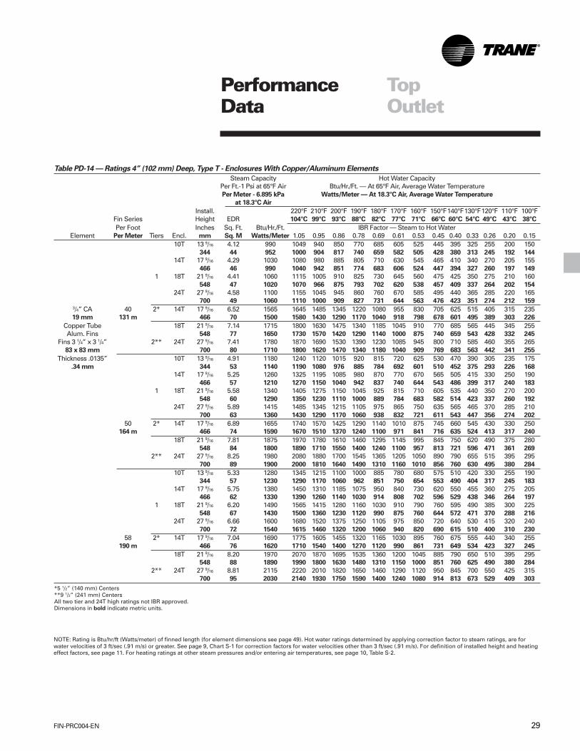
Table PD-14 — Ratings 4” (102 mm) Deep, Type T - Enclosures With Copper/Aluminum Elements
Steam Capacity Hot Water CapacityPer Ft.-1 Psi at 65°F Air Btu/Hr./Ft. — At 65°F Air, Average Water TemperaturePer Meter - 6.895 kPa Watts/Meter — At 18.3°C Air, Average Water Temperature
at 18.3°C Air
Install. 220°F 210°F 200°F 190°F 180°F 170°F 160°F 150°F140°F130°F120°F 110°F 100°FFin Series Height EDR 104°C 99°C 93°C 88°C 82°C 77°C 71°C 66°C 60°C 54°C 49°C 43°C 38°C
Per Foot Inches Sq. Ft. Btu/Hr./Ft. IBR Factor — Steam to Hot WaterElement Per Meter Tiers Encl. mm Sq. M Watts/Meter 1.05 0.95 0.86 0.78 0.69 0.61 0.53 0.45 0.40 0.33 0.26 0.20 0.15
10T 13 9/16 4.12 990 1049 940 850 770 685 605 525 445 395 325 255 200 150344 44 952 1000 904 817 740 659 582 505 428 380 313 245 192 144
14T 17 9/16 4.29 1030 1080 980 885 805 710 630 545 465 410 340 270 205 155466 46 990 1040 942 851 774 683 606 524 447 394 327 260 197 149
1 18T 21 9/16 4.41 1060 1115 1005 910 825 730 645 560 475 425 350 275 210 160548 47 1020 1070 966 875 793 702 620 538 457 409 337 264 202 154
24T 27 9/16 4.58 1100 1155 1045 945 860 760 670 585 495 440 365 285 220 165700 49 1060 1110 1000 909 827 731 644 563 476 423 351 274 212 159
3/4” CA 40 2* 14T 17 9/16 6.52 1565 1645 1485 1345 1220 1080 955 830 705 625 515 405 315 23519 mm 131 m 466 70 1500 1580 1430 1290 1170 1040 918 798 678 601 495 389 303 226
Copper Tube 18T 21 9/16 7.14 1715 1800 1630 1475 1340 1185 1045 910 770 685 565 445 345 255Alum. Fins 548 77 1650 1730 1570 1420 1290 1140 1000 875 740 659 543 428 332 245
Fins 3 1/4” x 3 1/4” 2** 24T 27 9/16 7.41 1780 1870 1690 1530 1390 1230 1085 945 800 710 585 460 355 26583 x 83 mm 700 80 1710 1800 1620 1470 1340 1180 1040 909 769 683 563 442 341 255
Thickness .0135” 10T 13 9/16 4.91 1180 1240 1120 1015 920 815 720 625 530 470 390 305 235 175.34 mm 344 53 1140 1190 1080 976 885 784 692 601 510 452 375 293 226 168
14T 17 9/16 5.25 1260 1325 1195 1085 980 870 770 670 565 505 415 330 250 190466 57 1210 1270 1150 1040 942 837 740 644 543 486 399 317 240 183
1 18T 21 9/16 5.58 1340 1405 1275 1150 1045 925 815 710 605 535 440 350 270 200548 60 1290 1350 1230 1110 1000 889 784 683 582 514 423 337 260 192
24T 27 9/16 5.89 1415 1485 1345 1215 1105 975 865 750 635 565 465 370 285 210700 63 1360 1430 1290 1170 1060 938 832 721 611 543 447 356 274 202
50 2* 14T 17 9/16 6.89 1655 1740 1570 1425 1290 1140 1010 875 745 660 545 430 330 250164 m 466 74 1590 1670 1510 1370 1240 1100 971 841 716 635 524 413 317 240
18T 21 9/16 7.81 1875 1970 1780 1610 1460 1295 1145 995 845 750 620 490 375 280548 84 1800 1890 1710 1550 1400 1240 1100 957 813 721 596 471 361 269
2** 24T 27 9/16 8.25 1980 2080 1880 1700 1545 1365 1205 1050 890 790 655 515 395 295700 89 1900 2000 1810 1640 1490 1310 1160 1010 856 760 630 495 380 284
10T 13 9/16 5.33 1280 1345 1215 1100 1000 885 780 680 575 510 420 330 255 190344 57 1230 1290 1170 1060 962 851 750 654 553 490 404 317 245 183
14T 17 9/16 5.75 1380 1450 1310 1185 1075 950 840 730 620 550 455 360 275 205466 62 1330 1390 1260 1140 1030 914 808 702 596 529 438 346 264 197
1 18T 21 9/16 6.20 1490 1565 1415 1280 1160 1030 910 790 760 595 490 385 300 225548 67 1430 1500 1360 1230 1120 990 875 760 644 572 471 370 288 216
24T 27 9/16 6.66 1600 1680 1520 1375 1250 1105 975 850 720 640 530 415 320 240700 72 1540 1615 1460 1320 1200 1060 940 820 690 615 510 400 310 230
58 2* 14T 17 9/16 7.04 1690 1775 1605 1455 1320 1165 1030 895 760 675 555 440 340 255190 m 466 76 1620 1710 1540 1400 1270 1120 990 861 731 649 534 423 327 245
18T 21 9/16 8.20 1970 2070 1870 1695 1535 1360 1200 1045 885 790 650 510 395 295548 88 1890 1990 1800 1630 1480 1310 1150 1000 851 760 625 490 380 284
2** 24T 27 9/16 8.81 2115 2220 2010 1820 1650 1460 1290 1120 950 845 700 550 425 315700 95 2030 2140 1930 1750 1590 1400 1240 1080 914 813 673 529 409 303
*5 1/2” (140 mm) Centers**9 1/2” (241 mm) CentersAll two tier and 24T high ratings not IBR approved.Dimensions in bold indicate metric units.
NOTE: Rating is Btu/hr/ft (Watts/meter) of finned length (for element dimensions see page 49). Hot water ratings determined by applying correction factor to steam ratings, are forwater velocities of 3 ft/sec (.91 m/s) or greater. See page 9, Chart S-1 for correction factors for water velocities other than 3 ft/sec (.91 m/s). For definition of installed height and heatingeffect factors, see page 11. For heating ratings at other steam pressures and/or entering air temperatures, see page 10, Table S-2.

FIN-PRC004-EN30
Table PD-15 — Ratings 4” (102 mm) Deep, Type T - Enclosures With Copper/Aluminum Elements
Steam Capacity Hot Water CapacityPer Ft.-1 Psi at 65°F Air Btu/Hr./Ft. — At 65°F Air, Average Water TemperaturePer Meter - 6.895 kPa Watts/Meter — At 18.3°C Air, Average Water Temperature
at 18.3°C Air
Install. 220°F 210°F 200°F 190°F 180°F 170°F 160°F 150°F140°F130°F120°F 110°F 100°FFin Series Height EDR 104°C 99°C 93°C 88°C 82°C 77°C 71°C 66°C 60°C 54°C 49°C 43°C 38°C
Per Foot Inches Sq. Ft. Btu/Hr./Ft. IBR Factor — Steam to Hot WaterElement Per Meter Tiers Encl. mm Sq. M Watts/Meter 1.05 0.95 0.86 0.78 0.69 0.61 0.53 0.45 0.40 0.33 0.26 0.20 0.15
10T 13 9/16 4.20 1010 1060 960 870 790 695 615 535 455 405 335 260 200 150344 45 971 1020 923 837 760 668 591 514 438 389 322 250 192 144
14T 17 9/16 4.37 1050 1100 995 905 820 725 640 555 470 420 345 275 210 155466 47 1010 1060 957 870 789 697 615 534 452 404 332 264 202 149
1 18T 21 9/16 4.50 1080 1135 1025 930 840 745 660 570 485 430 355 280 215 160548 48 1040 1090 986 894 808 716 635 548 466 413 341 269 207 154
24T 27 9/16 4.66 1120 1175 1065 965 875 770 685 595 505 450 370 290 225 170700 50 1080 1130 1029 928 841 740 659 572 486 433 356 279 216 163
1” CA 40 2* 14T 17 9/16 6.60 1585 1665 1505 1365 1235 1095 965 840 715 635 525 410 315 23525 mm 131m 466 71 1520 1600 1450 1310 1190 1050 928 808 688 611 505 394 303 226
Cooper Tube 18T 21 9/16 7.16 1720 1805 1635 1480 1340 1185 1050 910 775 690 565 445 345 260Alum. Fins 548 77 1650 1740 1570 1420 1290 1140 1010 875 745 664 543 428 332 250
Fins 3 1/4” x 3 1/4” 2** 24T 27 9/16 7.41 1780 1870 1690 1530 1390 1230 1085 945 800 710 585 460 355 26583 x 83 mm 700 80 1710 1800 1620 1470 1340 1180 1040 909 769 683 563 442 341 255
Thickness .0135” 10T 13 9/16 4.91 1180 1240 1120 1015 920 815 720 625 530 470 390 305 235 175.34 mm 344 53 1140 1190 1080 976 885 784 692 601 510 452 375 293 226 168
14T 17 9/16 5.29 1270 1335 1205 1090 990 875 775 675 570 510 420 330 255 190466 57 1220 1280 1160 1050 952 841 745 649 548 490 404 317 245 183
1 18T 21 9/16 5.62 1350 1420 1280 1160 1055 930 825 715 610 540 445 350 270 200548 60 1300 1360 1230 1120 1010 894 793 688 587 519 428 337 260 192
24T 27 9/16 5.93 1425 1495 1355 1225 1110 985 870 755 640 570 470 370 285 215700 64 1370 1440 1300 1180 1070 947 837 726 615 548 452 356 274 207
50 2* 14T 17 9/16 6.75 1620 1700 1540 1395 1265 1120 990 860 730 650 535 420 325 245164 m 466 73 1560 1640 1480 1340 1220 1080 952 827 702 625 514 404 313 236
18T 21 9/16 7.66 1840 1930 1750 1580 1435 1270 1120 975 830 735 605 480 370 275548 82 1770 1860 1680 1520 1380 1220 1080 938 798 707 582 462 356 264
2** 24T 27 9/16 8.08 1940 2035 1845 1670 1515 1340 1185 1030 875 775 640 505 390 290700 87 1870 1970 1770 1610 1460 1290 1140 990 841 745 615 486 375 279
10T 13 9/16 5.33 1280 1345 1215 1100 1000 885 780 680 575 510 420 330 255 190344 57 1230 1290 1170 1060 962 851 750 654 553 490 404 317 245 183
1 14T 17 9/16 5.79 1390 1460 1320 1195 1085 960 850 735 625 555 460 360 280 210466 62 1340 1400 1270 1150 1040 923 817 707 601 534 442 346 269 202
18T 21 9/16 6.25 1500 1575 1425 1290 1170 1035 915 795 675 600 495 390 300 225548 67 1440 1515 1370 1240 1125 995 880 765 650 575 475 375 290 215
24T 27 9/16 6.73 1615 1695 1535 1390 1260 1115 985 855 725 645 530 420 325 240700 72 1550 1630 1480 1340 1210 1070 947 822 697 620 510 404 313 231
58 2* 14T 17 9/16 6.81 1635 1715 1555 1405 1275 1130 995 865 735 655 540 425 325 245190 m 466 73 1570 1650 1500 1350 1230 1090 957 832 707 630 519 409 313 236
18T 21 9/16 7.93 1905 2000 1810 1640 1485 1315 1160 1010 855 760 630 495 380 285548 85 1830 1920 1740 1580 1430 1260 1120 971 822 731 606 476 365 274
2** 24T 27 9/16 8.54 2050 2150 1950 1765 1600 1415 1250 1085 920 820 675 535 410 310700 92 1970 2070 1880 1700 1540 1360 1200 1040 885 789 649 514 394 298
*5 1/2” (140 mm) Centers**9 1/2” (241 mm) CentersAll two tier and 24T high ratings not IBR approved.Dimensions in bold indicate metric units.
PerformanceData
TopOutlet

31FIN-PRC004-EN
PerformanceData
TopOutlet
Table PD-16 — Ratings 4” (102 mm) Deep, Type T - Enclosures With Copper/Aluminum Elements
Steam Capacity Hot Water CapacityPer Ft.-1 Psi at 65°F Air Btu/Hr./Ft. — At 65°F Air, Average Water TemperaturePer Meter - 6.895 kPa Watts/Meter — At 18.3°C Air, Average Water Temperature
at 18.3°C Air
Install. 220°F 210°F 200°F 190°F 180°F 170°F 160°F 150°F140°F130°F120°F 110°F 100°FFin Series Height EDR 104°C 99°C 93°C 88°C 82°C 77°C 71°C 66°C 60°C 54°C 49°C 43°C 38°C
Per Foot Inches Sq. Ft. Btu/Hr./Ft. IBR Factor — Steam to Hot WaterElement Per Meter Tiers Encl. mm Sq. M Watts/Meter 1.05 0.95 0.86 0.78 0.69 0.61 0.53 0.45 0.40 0.33 0.26 0.20 0.15
10T 13 9/16 4.25 1020 1070 970 875 795 705 620 540 460 410 335 265 205 150344 46 981 1030 933 840 764 678 596 519 442 394 322 255 197 144
14T 17 9/16 4.41 1060 1115 1005 910 825 730 645 560 475 425 350 275 210 160466 47 1029 1070 966 875 793 702 620 538 457 409 337 264 202 154
1 18T 21 9/16 4.58 1100 1155 1045 945 860 760 670 585 495 440 365 285 220 165548 49 1060 1110 1000 909 827 731 644 563 476 423 351 274 212 159
24T 27 9/16 4.75 1140 1195 1085 970 890 785 695 605 515 455 375 295 230 170700 51 1100 1150 1040 933 856 755 668 582 495 438 361 284 221 163
1 1/4” CA 40 2* 14T 17 9/16 6.54 1570 1650 1490 1350 1225 1085 960 830 705 630 520 410 315 23532 mm 131 m 466 70 1510 1590 1430 1300 1180 1040 923 798 678 606 500 394 303 226
Copper Tube 18T 21 9/16 7.12 1710 1795 1625 1470 1335 1180 1045 905 770 685 565 445 340 255Alum. Fins 548 77 1640 1730 1560 1410 1280 1140 1000 870 740 659 543 428 327 245
Fins 3 1/4” x 3 1/4” 2** 24T 27 9/16 7.39 1775 1865 1685 1525 1385 1225 1080 940 800 710 585 460 355 26583 x 83 mm 700 80 1710 1790 1620 1470 1330 1180 1040 904 769 683 563 442 341 255
Thickness .0135” 10T 13 9/16 4.95 1190 1250 1130 1025 930 820 725 630 535 475 390 310 240 180.34 mm 344 53 1140 1200 1090 986 894 789 697 606 514 457 375 298 231 173
14T 17 9/16 5.33 1280 1345 1215 1100 1000 885 780 680 575 510 420 330 255 190466 57 1230 1290 1170 1060 962 851 750 654 553 490 404 317 245 183
1 18T 21 9/16 5.70 1370 1440 1300 1180 1070 945 835 725 615 550 450 355 275 205548 61 1320 1380 1250 1140 1030 909 803 697 591 529 433 341 264 197
24T 27 9/16 6.02 1445 1515 1370 1240 1125 995 880 765 650 580 475 375 290 215700 65 1390 1460 1320 1190 1080 957 846 736 625 558 457 361 279 207
50 2* 14T 17 9/16 6.58 1580 1660 1500 1360 1230 1090 965 835 710 630 520 410 315 235164 m 466 71 1520 1600 1440 1310 1180 1050 928 803 683 606 500 394 303 226
18T 21 9/16 7.50 1800 1890 1620 1550 1405 1240 1100 955 810 720 595 470 360 270548 81 1730 1820 1560 1490 1350 1190 1060 918 779 692 572 452 346 260
2** 24T 27 9/16 7.91 1900 1995 1805 1635 1480 1310 1160 1005 855 760 625 495 380 285700 85 1830 1920 1740 1570 1420 1260 1120 966 822 731 601 476 365 274
10T 13 9/16 5.33 1280 1345 1215 1100 1000 885 780 680 575 510 420 330 255 190344 57 1230 1290 1170 1060 962 851 750 654 553 490 404 317 245 183
14T 17 9/16 5.83 1400 1470 1330 1205 1090 965 855 740 630 560 460 365 280 210466 63 1350 1410 1280 1160 1050 928 822 712 606 538 442 351 269 202
1 18T 21 9/16 6.29 1510 1585 1360 1300 1180 1040 920 800 680 605 500 390 300 225548 68 1450 1520 1310 1250 1140 1000 885 769 654 582 481 375 288 216
24T 27 9/16 6.77 1625 1705 1545 1400 1270 1120 990 860 730 650 535 420 325 245700 73 1560 1640 1490 1350 1200 1080 952 827 702 625 514 404 313 236
58 2* 14T 17 9/16 6.66 1600 1680 1520 1375 1250 1105 975 850 720 640 530 415 320 240190 m 466 72 1540 1620 1460 1320 1200 1060 938 817 692 615 510 399 308 231
18T 21 9/16 7.62 1830 1920 1740 1575 1425 1260 1115 970 825 730 605 475 365 275548 82 1760 1850 1670 1520 1370 1210 1070 933 793 702 582 457 351 264
2** 24T 27 9/16 8.18 1965 2065 1865 1690 1530 1355 1200 1040 885 785 650 510 395 295700 88 1890 1990 1790 1620 1470 1300 1150 1000 851 755 625 490 380 284
*5 1/2” (140 mm) Centers**9 1/2” (241 mm) CentersAll two tier and 24T high ratings not IBR approved.Dimensions in bold indicate metric units.

FIN-PRC004-EN32
PerformanceData
TopOutlet
Table PD-17 — Ratings 6” (152 mm) Deep, Type T - Enclosures With Copper/Aluminum Elements
Steam Capacity Hot Water CapacityPer Ft.-1 Psi at 65°F Air Btu/Hr./Ft. — At 65°F Air, Average Water TemperaturePer Meter - 6.895 kPa Watts/Meter — At 18.3°C Air, Average Water Temperature
at 18.3°C Air
Install. 220°F 210°F 200°F 190°F 180°F 170°F 160°F 150°F140°F130°F120°F 110°F 100°FFin Series Height EDR 104°C 99°C 93°C 88°C 82°C 77°C 71°C 66°C 60°C 54°C 49°C 43°C 38°C
Per Foot Inches Sq. Ft. Btu/Hr./Ft. IBR Factor — Steam to Hot WaterElement Per Meter Tiers Encl. mm Sq. M Watts/Meter 1.05 0.95 0.86 0.78 0.69 0.61 0.53 0.45 0.40 0.33 0.26 0.20 0.15
12T 15 9/16 6.12 1470 1545 1395 1265 1145 1015 895 780 660 590 485 380 295 220395 66 1410 1490 1340 1220 1100 976 861 750 635 567 466 365 284 212
16T 19 9/16 6.25 1500 1575 1425 1290 1170 1035 915 795 675 600 495 390 300 225497 67 1440 1520 1370 1240 1120 995 880 764 649 577 476 375 288 216
1 20T 23 9/16 6.41 1540 1615 1465 1325 1200 1060 940 815 690 615 510 400 310 230598 69 1480 1550 1410 1270 1150 1020 904 784 664 591 490 385 298 221
24T 27 9/16 6.64 1595 1675 1515 1370 1245 1100 970 845 720 640 525 415 320 240700 71 1530 1610 1460 1320 1200 1060 933 813 692 615 505 399 308 231
1 1/4” CA 40 2* 16T 19 9/16 9.85 2365 2480 2245 2035 1845 1630 1440 1250 1065 945 780 615 470 35532 mm 131 m 497 106 2270 2380 2160 1960 1770 1570 1380 1200 1020 909 750 591 452 341
Copper Tube 20T 23 9/16 10.43 2505 2630 2380 2155 1955 1730 1530 1330 1125 1000 825 650 500 375Alum. Fins 598 112 2410 2530 2290 2070 1880 1660 1470 1280 1080 962 793 625 481 361
Fins 3 1/4” x 5 1/4” 2** 24T 27 9/16 10.81 2595 2725 2465 2230 2025 1790 1580 1375 1165 1040 855 675 520 38083 x 133 mm 700 116 2500 2620 2370 2140 1950 1720 1520 1320 1120 1000 822 649 500 365
Thickness .0135” 12T 15 9/16 7.58 1820 1910 1730 1565 1420 1255 1110 965 820 730 600 475 365 275.34 mm 395 82 1750 1840 1660 1500 1360 1210 1070 928 789 702 577 457 351 264
16T 19 9/16 7.95 1910 2005 1815 1640 1490 1315 1165 1010 860 765 630 495 380 285497 86 1840 1930 1740 1580 1430 1260 1120 971 827 736 606 476 365 274
1 20T 23 9/16 8.37 2010 2110 1910 1730 1565 1390 1225 1065 905 805 665 520 400 300598 90 1930 2030 1840 1660 1500 1340 1180 1020 870 774 639 500 385 288
24T 27 9/16 8.83 2120 2225 2015 1825 1655 1460 1295 1125 955 850 700 550 425 320700 95 2040 2140 1940 1760 1590 1400 1240 1080 918 817 673 529 409 308
50 2* 16T 19 9/16 10.37 2490 2615 2365 2140 1940 1720 1520 1320 1120 995 820 645 500 370164 m 497 112 2390 2520 2270 2060 1870 1650 1460 1270 1080 957 789 620 481 356
20T 23 9/16 11.41 2740 2875 2600 2355 2135 1890 1670 1450 1230 1095 905 710 550 410598 123 2640 2760 2500 2260 2050 1820 1610 1390 1180 1050 870 683 529 394
2** 24T 27 9/16 12.04 2890 3035 2745 2485 2255 1995 1760 1530 1300 1155 955 750 580 435700 130 2780 2920 2640 2390 2170 1920 1690 1470 1250 1110 918 721 558 418
12T 15 9/16 8.33 2000 2100 1900 1720 1560 1380 1220 1060 900 800 660 520 400 300395 90 1920 2020 1830 1650 1500 1300 1170 1020 865 769 635 500 385 288
16T 19 9/16 8.87 2130 2235 2025 1830 1660 1470 1300 1130 860 850 700 555 425 320497 95 2050 2150 1950 1760 1600 1410 1250 1090 923 817 673 534 409 308
1 20T 23 9/16 9.41 2260 2375 2145 1945 1760 1560 1380 1200 1015 905 745 590 450 340598 101 2170 2280 2060 1870 1690 1500 1330 1150 976 870 716 567 433 327
24T 27 9/16 10.12 2430 2550 2310 2090 1895 1675 1480 1290 1095 970 800 630 485 365700 109 2340 2450 2220 2010 1820 1610 1420 1240 1050 933 769 606 466 351
58 2* 16T 19 9/16 10.64 2555 2680 2425 2195 1990 1760 1560 1355 1150 1020 845 665 510 385190 m 497 115 2460 2580 2330 2110 1910 1690 1500 1300 1110 981 813 639 490 370
20T 23 9/16 12.02 2885 3030 2740 2480 2250 1990 1760 1530 1300 1155 950 750 575 430598 129 2770 2910 2640 2380 2160 1910 1690 1470 1250 1110 914 721 553 413
2* 24T 27 9/16 12.91 3100 3255 2945 2665 2420 2135 1890 1645 1395 1240 1025 805 620 465700 139 2980 3130 2830 2560 2330 2050 1820 1580 1340 1190 986 774 596 447
*5 1/2” (140 mm) Centers**9 1/2” (241 mm) CentersAll two tier and 24T high ratings not IBR approved.Dimensions in bold indicate metric units.

33FIN-PRC004-EN
PerformanceData
TopOutlet
Table PD-18 — Ratings 6” (152 mm) Deep, Type T - Enclosures With Steel Elements
Steam Capacity Hot Water CapacityPer Ft.-1 Psi at 65°F Air Btu/Hr./Ft. — At 65°F Air, Average Water TemperaturePer Meter - 6.895 kPa Watts/Meter — At 18.3°C Air, Average Water Temperature
at 18.3°C Air
Install. 220°F 210°F 200°F 190°F 180°F 170°F 160°F 150°F140°F130°F120°F 110°F 100°FFin Series Height EDR 104°C 99°C 93°C 88°C 82°C 77°C 71°C 66°C 60°C 54°C 49°C 43°C 38°C
Per Foot Inches Sq. Ft. Btu/Hr./Ft. IBR Factor — Steam to Hot WaterElement Per Meter Tiers Encl. mm Sq. M Watts/Meter 1.05 0.95 0.86 0.78 0.69 0.61 0.53 0.45 0.40 0.33 0.26 0.20 0.15
12T 15 5/8 6.15 1480 1550 1410 1270 1150 1020 900 785 665 590 485 385 295 220397 66 1420 1490 1360 1220 1110 981 865 755 639 567 466 370 284 212
16T 19 5/8 6.40 1540 1620 1460 1320 1200 1060 940 815 690 615 505 400 305 230498 69 1480 1560 1400 1270 1150 1020 904 784 664 591 486 385 293 221
1 1/4” Steel 1 20T 23 5/8 6.65 1590 1670 1510 1370 1240 1100 970 840 715 635 525 410 315 23532 mm 600 72 1530 1610 1450 1320 1190 1060 933 808 688 611 505 394 303 226
Steel Tube 24T 27 5/8 6.99 1680 1765 1595 1445 1310 1160 1025 890 755 670 555 435 335 250Steel Fins 702 75 1620 1700 1530 1390 1260 1120 986 856 726 644 534 418 322 240
Fins 2 1/2” x 5 1/4” 52 16T 19 5/8 8.90 2140 2250 2030 1840 1670 1480 1310 1135 860 855 705 555 425 32065 x 133 mm 171 m 498 96 2060 2160 1950 1770 1610 1420 1260 1090 923 822 678 534 409 308
Thickness .027” 2* 20T 23 5/8 9.45 2270 2380 2160 1950 1770 1570 1380 1205 1020 905 750 590 455 340.69 mm 600 102 2180 2290 2080 1880 1700 1510 1330 1160 981 870 721 567 438 327
24T 27 5/8 9.94 2385 2505 2265 2050 1860 1645 1455 1265 1075 955 785 620 475 360702 107 2290 2410 2180 1970 1790 1580 1400 1220 1030 918 755 596 457 346
20T 23 5/8 9.85 2360 2480 2240 2030 1840 1630 1440 1250 1060 945 775 610 470 350600 106 2270 2380 2150 1950 1770 1570 1380 1200 1020 909 745 587 452 337
2* 24T 27 5/8 10.36 2485 2610 2360 2135 1940 1715 1515 1315 1120 995 820 645 495 375702 112 2390 2510 2270 2050 1870 1650 1460 1260 1080 957 789 620 476 361
*4” (102 mm) Centers**8” (203 mm) Centers24T High ratings not IBR approved.Dimensions in bold indicate metric units.
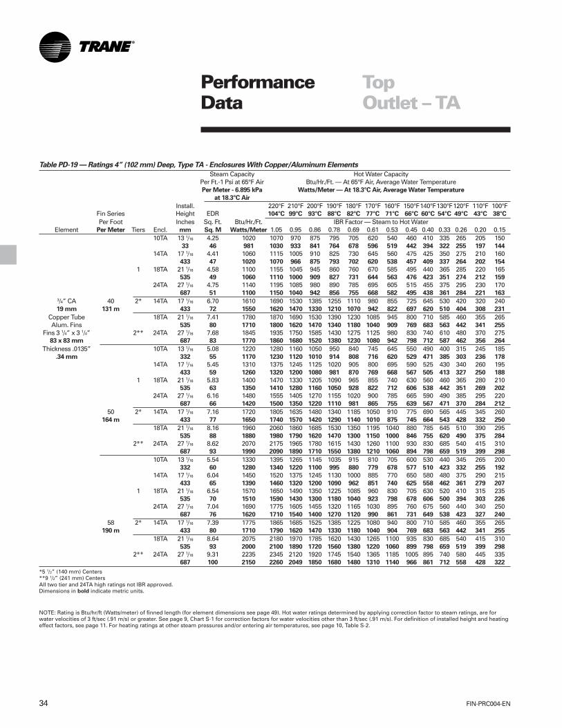
FIN-PRC004-EN34
PerformanceData
TopOutlet – TA
Table PD-19 — Ratings 4” (102 mm) Deep, Type TA - Enclosures With Copper/Aluminum Elements
Steam Capacity Hot Water CapacityPer Ft.-1 Psi at 65°F Air Btu/Hr./Ft. — At 65°F Air, Average Water TemperaturePer Meter - 6.895 kPa Watts/Meter — At 18.3°C Air, Average Water Temperature
at 18.3°C Air
Install. 220°F 210°F 200°F 190°F 180°F 170°F 160°F 150°F140°F130°F120°F 110°F 100°FFin Series Height EDR 104°C 99°C 93°C 88°C 82°C 77°C 71°C 66°C 60°C 54°C 49°C 43°C 38°C
Per Foot Inches Sq. Ft. Btu/Hr./Ft. IBR Factor — Steam to Hot WaterElement Per Meter Tiers Encl. mm Sq. M Watts/Meter 1.05 0.95 0.86 0.78 0.69 0.61 0.53 0.45 0.40 0.33 0.26 0.20 0.15
10TA 13 1/16 4.25 1020 1070 970 875 795 705 620 540 460 410 335 265 205 15033 46 981 1030 933 841 764 678 596 519 442 394 322 255 197 144
14TA 17 1/16 4.41 1060 1115 1005 910 825 730 645 560 475 425 350 275 210 160433 47 1020 1070 966 875 793 702 620 538 457 409 337 264 202 154
1 18TA 21 1/16 4.58 1100 1155 1045 945 860 760 670 585 495 440 365 285 220 165535 49 1060 1110 1000 909 827 731 644 563 476 423 351 274 212 159
24TA 27 1/16 4.75 1140 1195 1085 980 890 785 695 605 515 455 375 295 230 170687 51 1100 1150 1040 942 856 755 668 582 495 438 361 284 221 163
3/4” CA 40 2* 14TA 17 1/16 6.70 1610 1690 1530 1385 1255 1110 980 855 725 645 530 420 320 24019 mm 131 m 433 72 1550 1620 1470 1330 1210 1070 942 822 697 620 510 404 308 231
Copper Tube 18TA 21 1/16 7.41 1780 1870 1690 1530 1390 1230 1085 945 800 710 585 460 355 265Alum. Fins 535 80 1710 1800 1620 1470 1340 1180 1040 909 769 683 563 442 341 255
Fins 3 1/4” x 3 1/4” 2** 24TA 27 1/16 7.68 1845 1935 1750 1585 1430 1275 1125 980 830 740 610 480 370 27583 x 83 mm 687 83 1770 1860 1680 1520 1380 1230 1080 942 798 712 587 462 356 264
Thickness .0135” 10TA 13 1/16 5.08 1220 1280 1160 1050 950 840 745 645 550 490 400 315 245 185.34 mm 332 55 1170 1230 1120 1010 914 808 716 620 529 471 385 303 236 178
14TA 17 1/16 5.45 1310 1375 1245 1125 1020 905 800 695 590 525 430 340 260 195433 59 1260 1320 1200 1080 981 870 769 668 567 505 413 327 250 188
1 18TA 21 1/16 5.83 1400 1470 1330 1205 1090 965 855 740 630 560 460 365 280 210535 63 1350 1410 1280 1160 1050 928 822 712 606 538 442 351 269 202
24TA 27 1/16 6.16 1480 1555 1405 1270 1155 1020 900 785 665 590 490 385 295 220687 66 1420 1500 1350 1220 1110 981 865 755 639 567 471 370 284 212
50 2* 14TA 17 1/16 7.16 1720 1805 1635 1480 1340 1185 1050 910 775 690 565 445 345 260164 m 433 77 1650 1740 1570 1420 1290 1140 1010 875 745 664 543 428 332 250
18TA 21 1/16 8.16 1960 2060 1860 1685 1530 1350 1195 1040 880 785 645 510 390 295535 88 1880 1980 1790 1620 1470 1300 1150 1000 846 755 620 490 375 284
2** 24TA 27 1/16 8.62 2070 2175 1965 1780 1615 1430 1260 1100 930 830 685 540 415 310687 93 1990 2090 1890 1710 1550 1380 1210 1060 894 798 659 519 399 298
10TA 13 1/16 5.54 1330 1395 1265 1145 1035 915 810 705 600 530 440 345 265 200332 60 1280 1340 1220 1100 995 880 779 678 577 510 423 332 255 192
14TA 17 1/16 6.04 1450 1520 1375 1245 1130 1000 885 770 650 580 480 375 290 215433 65 1390 1460 1320 1200 1090 962 851 740 625 558 462 361 279 207
1 18TA 21 1/16 6.54 1570 1650 1490 1350 1225 1085 960 830 705 630 520 410 315 235535 70 1510 1590 1430 1300 1180 1040 923 798 678 606 500 394 303 226
24TA 27 1/16 7.04 1690 1775 1605 1455 1320 1165 1030 895 760 675 560 440 340 250687 76 1620 1710 1540 1400 1270 1120 990 861 731 649 538 423 327 240
58 2* 14TA 17 1/16 7.39 1775 1865 1685 1525 1385 1225 1080 940 800 710 585 460 355 265190 m 433 80 1710 1790 1620 1470 1330 1180 1040 904 769 683 563 442 341 255
18TA 21 1/16 8.64 2075 2180 1970 1785 1620 1430 1265 1100 935 830 685 540 415 310535 93 2000 2100 1890 1720 1560 1380 1220 1060 899 798 659 519 399 298
2** 24TA 27 1/16 9.31 2235 2345 2120 1920 1745 1540 1365 1185 1005 895 740 580 445 335687 100 2150 2260 2049 1850 1680 1480 1310 1140 966 861 712 558 428 322
*5 1/2” (140 mm) Centers**9 1/2” (241 mm) CentersAll two tier and 24TA high ratings not IBR approved.Dimensions in bold indicate metric units.
NOTE: Rating is Btu/hr/ft (Watts/meter) of finned length (for element dimensions see page 49). Hot water ratings determined by applying correction factor to steam ratings, are forwater velocities of 3 ft/sec (.91 m/s) or greater. See page 9, Chart S-1 for correction factors for water velocities other than 3 ft/sec (.91 m/s). For definition of installed height and heatingeffect factors, see page 11. For heating ratings at other steam pressures and/or entering air temperatures, see page 10, Table S-2.

35FIN-PRC004-EN
PerformanceData
TopOutlet – TA
Table PD-20 — Ratings 4” (102 mm) Deep, Type TA - Enclosures With Copper/Aluminum Element
Steam Capacity Hot Water CapacityPer Ft.-1 Psi at 65°F Air Btu/Hr./Ft. — At 65°F Air, Average Water TemperaturePer Meter - 6.895 kPa Watts/Meter — At 18.3°C Air, Average Water Temperature
at 18.3°C air
Install. 220°F 210°F 200°F 190°F 180°F 170°F 160°F 150°F140°F130°F120°F 110°F 100°FFin Series Height EDR 104°C 99°C 93°C 88°C 82°C 77°C 71°C 66°C 60°C 54°C 49°C 43°C 38°C
Per Foot Inches Sq. Ft. Btu/Hr./Ft. IBR Factor — Steam to Hot WaterElement Per Meter Tiers Encl. mm Sq. M Watts/Meter 1.05 0.95 0.86 0.78 0.69 0.61 0.53 0.45 0.40 0.33 0.26 0.20 0.15
10TA 13 1/16 4.29 1030 1080 980 885 805 710 630 545 465 410 340 265 205 155332 46 990 1040 942 851 774 683 606 524 447 394 327 255 197 149
14TA 17 1/16 4.45 1070 1125 1015 920 835 740 650 565 480 430 355 280 215 160433 48 1030 1080 976 885 803 712 625 543 462 413 341 269 207 154
1 18 TA 21 1/16 4.66 1120 1175 1065 965 875 770 685 595 505 450 370 290 225 170535 50 1080 1130 1020 928 841 740 659 572 486 433 356 279 216 163
24TA 27 1/16 4.83 1160 1280 1100 1000 905 800 710 615 520 465 380 300 230 175687 52 1120 1230 1060 962 870 769 683 591 500 447 365 288 221 168
1” CA 40 2* 14TA 17 1/16 6.73 1615 1695 1535 1390 1260 1115 985 855 725 645 530 420 325 24025 mm 131m 433 72 1550 1630 1480 1340 1210 1070 947 822 697 620 510 404 313 231
Copper Tube 18TA 21 1/16 7.41 1780 1870 1690 1530 1390 1230 1085 945 800 710 585 460 355 265Alum. Fins 535 80 1710 1800 1620 1470 1340 1180 1040 909 769 683 563 442 341 255
Fins 3 1/4” x 3 1/4” 2** 24TA 27 1/16 7.68 1845 1935 1750 1585 1440 1275 1125 980 830 740 610 480 370 27583 x 83 mm 687 83 1770 1860 1680 1520 1380 1230 1080 942 798 712 587 462 356 264
Thickness .0135” 10TA 13 1/16 5.08 1220 1280 1160 1050 950 840 745 645 550 490 400 315 245 185.34 mm 332 55 1170 1230 1120 1010 914 808 716 620 529 471 385 303 236 178
14TA 17 1/16 5.50 1320 1385 1255 1135 1030 910 805 700 595 530 435 345 265 200433 59 1270 1330 1210 1090 990 875 774 673 572 510 418 332 255 192
1 18TA 21 1/16 5.91 1420 1490 1350 1220 1110 980 865 750 640 570 470 370 285 215535 64 1360 1430 1300 1170 1070 942 832 721 615 548 452 356 274 207
24TA 27 1/16 6.25 1500 1575 1425 1290 1170 1035 915 795 675 600 495 390 300 225687 67 1440 1520 1370 1240 1120 995 880 764 649 577 476 375 288 216
50 2* 14TA 17 1/16 7.00 1680 1765 1595 1445 1310 1160 1025 890 755 670 555 435 335 250164 m 433 75 1620 1700 1530 1390 1260 1120 986 856 726 644 534 418 322 240
18TA 21 1/16 8.04 1930 2025 1835 1660 1505 1330 1175 1020 870 770 635 500 385 290535 87 1860 1950 1760 1600 1450 1280 1130 981 837 740 611 481 370 279
2** 24TA 27 1/16 8.50 2040 2140 1940 1755 1590 1410 1245 1080 920 815 675 530 410 305687 91 1960 2060 1870 1690 1530 1360 1200 1040 885 784 649 510 394 293
10TA 13 1/16 5.54 1330 1395 1265 1145 1035 920 810 705 600 530 440 345 265 200332 60 1280 1340 1220 1100 995 885 779 678 577 510 423 332 255 192
14TA 17 1/16 6.08 1460 1535 1385 1255 1140 1005 890 775 655 585 480 380 290 220433 65 1400 1480 1330 1210 1100 966 856 745 630 563 462 365 279 212
1 18TA 21 1/16 6.62 1590 1670 1510 1365 1240 1095 970 840 715 635 525 415 320 240535 71 1530 1610 1450 1310 1190 1050 933 808 688 611 505 399 308 231
24TA 27 1/16 7.12 1710 1795 1625 1470 1335 1180 1049 905 770 685 510 440 335 250687 77 1640 1730 1560 1410 1280 1140 1000 870 740 659 490 423 322 240
58 2* 14TA 17 1/16 7.16 1720 1795 1625 1470 1335 1180 1045 905 770 685 565 445 340 255190 m 433 77 1650 1730 1560 1410 1280 1140 1000 870 740 659 543 428 327 245
18TA 21 1/16 8.41 2020 2120 1920 1735 1575 1395 1230 1070 910 810 665 525 405 305535 91 1940 2040 1850 1670 1520 1340 1180 1030 875 779 639 505 389 293
2** 24TA 27 1/16 9.04 2170 2260 2060 1865 1690 1495 1325 1150 975 870 715 565 435 325687 97 2090 2170 1980 1790 1620 1440 1270 1110 928 837 688 543 418 313
*5 1/2” (140 mm) Centers**9 1/2” (241 mm) CentersAll two tier and 24TA high ratings not IBR approved.Dimensions in bold indicate metric units.

FIN-PRC004-EN36
PerformanceData
TopOutlet – TA
Table PD-21 — Ratings 4” (102 mm) Deep, Type TA - Enclosures With Copper/Aluminum Elements
Steam Capacity Hot Water CapacityPer Ft.-1 Psi at 65°F Air Btu/Hr./Ft. — At 65°F Air, Average Water TemperaturePer Meter - 6.895 kPa Watts/Meter — At 18.3°C Air, Average Water Temperature
at 18.3°C Air
Install. 220°F 210°F 200°F 190°F 180°F 170°F 160°F 150°F140°F130°F120°F 110°F 100°FFin Series Height EDR 104°C 99°C 93°C 88°C 82°C 77°C 71°C 66°C 60°C 54°C 49°C 43°C 38°C
Per Foot Inches Sq. Ft. Btu/Hr./Ft. IBR Factor — Steam to Hot WaterElement Per Meter Tiers Encl. mm Sq. M Watts/Meter 1.05 0.95 0.86 0.78 0.69 0.61 0.53 0.45 0.40 0.33 0.26 0.20 0.15
10TA 13 1/16 4.33 1040 1090 990 895 810 720 635 550 470 415 345 270 210 155332 47 1000 1050 952 861 779 692 611 529 452 399 332 260 202 149
14TA 17 1/16 4.54 1090 1145 1035 935 850 750 665 580 490 435 360 285 220 165433 49 1059 1100 995 899 817 721 639 558 471 418 346 274 212 159
1 18TA 21 1/16 4.75 1140 1195 1085 980 890 785 695 605 515 455 375 295 230 170535 51 1100 1150 1040 942 856 755 668 582 495 438 361 284 221 163
24TA 27 1/16 4.91 1180 1240 1120 1015 920 815 720 625 530 470 390 305 235 175687 53 1140 1190 1080 976 885 784 692 601 510 452 375 293 226 168
1 1/4” CA 40 2* 14TA 17 1/16 6.73 1615 1695 1535 1390 1260 1115 985 855 725 645 530 420 325 24032 mm 131 m 433 72 1550 1630 1480 1340 1210 1070 947 822 697 620 510 404 313 231
Copper Tube 18TA 21 1/16 7.39 1775 1865 1685 1525 1385 1225 1080 940 800 710 585 460 355 265Alum. Fins 535 80 1710 1790 1620 1470 1330 1180 1049 904 769 683 563 442 341 255
Fins 3 1/4” x 3 1/4” 2** 24TA 27 1/16 7.64 1835 1925 1745 1580 1430 1265 1120 970 825 735 605 475 365 27583 x 83 mm 687 82 1760 1850 1680 1520 1380 1220 1080 933 793 707 582 457 351 264
Thickness .0135” 10TA 13 1/16 5.12 1230 1290 1170 1060 960 850 750 650 555 490 405 320 245 185.34 mm 332 55 1180 1240 1120 1020 923 817 721 625 534 471 389 308 236 178
14TA 17 1/16 5.58 1340 1405 1275 1150 1045 925 815 710 605 535 440 350 270 200433 60 1290 1350 1230 1110 1000 889 784 683 582 514 423 337 260 192
1 18TA 21 1/16 6.00 1440 1510 1370 1240 1125 995 880 765 650 575 475 375 290 215535 65 1380 1450 1320 1190 1080 957 846 736 625 553 457 361 279 207
24TA 27 1/16 6.33 1520 1595 1445 1305 1185 1050 925 805 685 610 500 395 305 230687 68 1460 1530 1390 1260 1140 1010 889 774 659 587 481 380 293 221
50 2* 14TA 17 1/16 6.89 1655 1735 1570 1425 1290 1140 1010 875 745 660 545 430 330 250164 m 433 74 1590 1670 1510 1370 1240 1100 971 841 716 635 524 413 317 240
18TA 21 1/16 7.89 1895 1990 1800 1630 1480 1310 1155 1005 850 760 625 490 380 285535 85 1820 1910 1730 1570 1420 1260 1110 966 817 731 601 471 365 274
2** 24TA 27 1/16 8.33 2000 2100 1900 1720 1560 1380 1220 1060 900 800 660 520 400 300687 90 1920 2020 1830 1650 1500 1330 1170 1020 865 769 635 500 385 288
10TA 13 1/16 5.54 1330 1395 1265 1145 1035 915 810 705 600 530 430 345 265 200332 60 1280 1340 1220 1100 995 880 779 678 577 510 413 332 255 192
14TA 17 1/16 6.12 1470 1545 1395 1265 1145 1015 895 780 660 590 485 380 295 220433 66 1410 1490 1340 1220 1100 976 861 750 635 567 466 365 284 212
1 18TA 21 1/16 6.70 1610 1690 1530 1385 1255 1110 980 855 725 645 530 420 320 240535 72 1550 1620 1470 1330 1210 1070 942 822 697 620 510 404 308 231
24TA 27 1/16 7.20 1730 1815 1645 1490 1350 1195 1055 915 780 690 570 450 345 260687 78 1660 1740 1580 1430 1300 1150 1010 880 750 664 548 433 332 250
58 2* 14TA 17 1/16 7.00 1680 1765 1595 1445 1310 1160 1025 890 755 670 555 435 335 250190 m 433 75 1620 1700 1530 1390 1260 1120 986 856 726 644 534 418 322 240
18TA 21 1/16 8.12 1950 2050 1850 1675 1520 1345 1190 1035 880 780 645 505 390 290535 87 1880 1970 1780 1610 1460 1290 1140 995 846 750 620 486 375 279
2** 24TA 27 1/16 8.73 2095 2200 1990 1800 1635 1445 1280 1110 940 840 690 545 420 315687 94 2020 2120 1910 1730 1570 1390 1230 1070 904 808 664 524 404 303
*5 1/2” (140 mm) Centers**9 1/2” (241 mm) CentersAll two tier and 24TA high ratings not IBR approved.Dimensions in bold indicate metric units.

37FIN-PRC004-EN
PerformanceData
TopOutlet – TA
Table PD-22 — Ratings 6” (152 mm) Deep, Type TA - Enclosures With Copper/Aluminum Elements
Steam Capacity Hot Water CapacityPer Ft.-1 Psi at 65°F Air Btu/Hr./Ft. — At 65°F Air, Average Water TemperaturePer Meter - 6.895 kPa Watts/Meter — At 18.3°C Air, Average Water Temperature
at 18.3°C Air
Install. 220°F 210°F 200°F 190°F 180°F 170°F 160°F 150°F140°F130°F120°F 110°F 100°FFin Series Height EDR 104°C 99°C 93°C 88°C 82°C 77°C 71°C 66°C 60°C 54°C 49°C 43°C 38°C
Per Foot Inches Sq. Ft. Btu/Hr./Ft. IBR Factor — Steam to Hot WaterElement Per Meter Tiers Encl. mm Sq. M Watts/Meter 1.05 0.95 0.86 0.78 0.69 0.61 0.53 0.45 0.40 0.33 0.26 0.20 0.15
12TA 15 6.33 1520 1595 1445 1305 1185 1050 925 805 685 610 500 395 305 230381 68 1460 1530 1390 1260 1140 1010 889 774 659 587 481 380 293 221
16TA 19 6.50 1560 1640 1480 1340 1215 1075 950 825 700 625 515 405 310 235483 70 1500 1580 1420 1290 1170 1030 914 793 673 601 495 389 298 226
1 20TA 23 6.70 1610 1690 1530 1385 1255 1110 980 855 725 645 530 420 320 240584 72 1550 1620 1470 1330 1210 1070 942 822 697 620 510 404` 308 231
24TA 27 6.93 1665 1750 1580 1430 1300 1150 1015 880 750 665 550 430 335 250686 75 1600 1680 1520 1380 1250 1110 976 846 721 639 529 413 322 240
1 1/4” CA 40 2* 16TA 19 10.25 2460 2585 2335 2115 1920 1695 1500 1305 1105 985 810 640 490 37032 mm 131 m 483 110 2370 2490 2240 2030 1850 1630 1440 1260 1060 947 779 615 471 356
Copper Tube 20TA 23 10.89 2615 2745 2485 2250 2040 1805 1595 1385 1175 1045 860 680 525 390Alum. Fins 584 117 2520 2640 2390 2160 1960 1740 1530 1330 1130 1000 827 654 505 375
Fins 3 1/4” x 5 1/4” 2** 24TA 27 11.29 2710 2845 2575 2330 2115 1870 1655 1435 1220 1085 895 705 540 40583 x 133 mm 686 122 2610 2740 2480 2240 2030 1800 1590 1380 1170 1040 861 678 519 389
Thickness .0135” 12TA 15 7.95 1910 2005 1815 1640 1490 1320 1165 1010 860 765 630 495 380 285.34 mm 381 86 1840 1930 1740 1580 1430 1270 1120 971 827 736 606 476 365 274
16TA 19 8.41 2020 2120 1920 1735 1575 1395 1230 1070 910 810 665 525 405 305483 91 1940 2040 1850 1670 1520 1340 1180 1030 875 779 639 505 389 293
1 20TA 23 8.91 2140 2245 2035 1840 1670 1475 1305 1135 965 855 705 555 430 320584 96 2060 2160 1960 1770 1610 1420 1260 1090 928 822 678 534 413 308
24TA 27 9.39 2255 2370 2140 1940 1760 1555 1375 1195 1015 900 745 585 450 330686 101 2170 2280 2060 1870 1690 1500 1320 1150 976 865 716 563 433 317
50 2* 16TA 19 10.95 2630 2760 2500 2260 2050 1815 1605 1395 1185 1050 870 685 525 395164 m 483 118 2530 2650 2400 2170 1970 1740 1540 1340 1140 1010 837 659 505 380
20TA 23 12.16 2920 3065 2775 2510 2280 2015 1780 1550 1315 1170 965 760 585 440584 131 2810 2950 2670 2410 2190 1940 1710 1490 1260 1120 928 731 563 423
2** 24TA 27 12.81 3075 3230 2920 2645 2400 2120 1875 1630 1385 1230 1015 800 615 460686 138 2960 3110 2810 2540 2310 2040 1800 1570 1330 1180 976 769 591 442
12TA 15 8.79 2110 2215 2005 1815 1645 1455 1290 1120 950 845 695 550 420 315381 95 2030 2130 1930 1740 1580 1400 1240 1080 914 813 668 529 404 303
16TA 19 9.45 2270 2385 2155 1950 1770 1565 1385 1205 1020 910 750 590 455 340483 102 2180 2290 2070 1880 1700 1500 1330 1160 981 875 721 567 438 327
1 20TA 23 10.08 2420 2540 2300 2080 1890 1670 1475 1280 1090 970 800 630 485 365584 109 2330 2440 2210 2000 1820 1610 1420 1230 1050 933 769 606 466 351
24TA 27 10.83 2600 2730 2470 2235 2030 1795 1585 1380 1170 1040 860 675 520 390686 117 2500 2620 2380 2150 1950 1730 1520 1330 1120 1000 827 649 500 375
58 2* 16TA 19 11.33 2720 2855 2585 2340 2120 1875 1660 1440 1225 1090 900 705 545 410190 m 483 122 2620 2740 2490 2250 2040 1800 1600 1380 1180 1050 865 678 524 394
20TA 23 12.87 3090 3245 2935 2655 2410 2130 1885 1640 1390 1235 1020 805 620 465584 139 2970 3120 2820 2550 2320 2050 1810 1580 1340 1190 981 774 596 447
2** 24TA 27 13.83 3320 3485 3155 2855 2590 2290 2025 1760 1495 1330 1095 865 665 500686 149 3190 3350 3030 2740 2490 2200 1950 1690 1440 1280 1050 832 639 481
*5 1/2” (140 mm) Centers**9 1/2” (241 mm) CentersAll two tier and 24TA high ratings not IBR approved.Dimensions in bold indicate metric units.

FIN-PRC004-EN38
PerformanceData
TopOutlet – TA
Table PD-23 — Ratings 6” (152 mm) Deep, Type TA - Enclosures With Steel Elements
Steam Capacity Hot Water CapacityPer Ft.-1 Psi at 65°F Air Btu/Hr./Ft. — At 65°F Air, Average Water TemperaturePer Meter - 6.895 kPa Watts/Meter — At 18.3°C Air, Average Water Temperature
at 18.3°C Air
Install. 220°F 210°F 200°F 190°F 180°F 170°F 160°F 150°F140°F130°F120°F 110°F 100°FFin Series Height EDR 104°C 99°C 93°C 88°C 82°C 77°C 71°C 66°C 60°C 54°C 49°C 43°C 38°C
Per Foot Inches Sq. Ft. Btu/Hr./Ft. IBR Factor — Steam to Hot WaterElement Per Meter Tiers Encl. mm Sq. M Watts/Meter 1.05 0.95 0.86 0.78 0.69 0.61 0.53 0.45 0.40 0.33 0.26 0.20 0.15
12TA 15 1/4 6.50 1560 1640 1480 1340 1220 1080 950 825 700 625 515 405 310 230387 70 1500 1580 1420 1290 1170 1040 914 793 673 601 495 389 298 221
16TA 19 1/4 6.70 1610 1690 1530 1380 1260 1110 980 850 725 645 530 420 320 240489 72 1550 1620 1470 1330 1210 1070 942 817 697 620 510 404 308 231
1 1/4” Steel 1 20TA 23 1/4 6.90 1660 1740 1580 1430 1290 1150 1010 880 745 665 545 430 330 24532 mm 590 74 1600 1670 1520 1380 1240 1110 971 846 716 639 524 413 317 236
Steel Tube 24TA 27 1/4 7.26 1740 1825 1655 1495 1355 1200 1060 920 785 695 575 450 350 260Steel Fins 692 78 1670 1760 1590 1440 1300 1150 1020 885 755 668 553 433 337 250
Fins 2 1/2” x 5 1/4” 52 16TA 19 1/4 9.40 2250 2360 2140 1940 1760 1550 1370 1190 1010 900 740 585 450 33564 x 133 mm 171 m 489 101 2160 2270 2060 1870 1690 1490 1320 1140 971 865 712 563 433 322
Thickness .027” 2* 20TA 23 1/4 10.00 2400 2520 2280 2060 1870 1660 1460 1270 1080 960 790 625 480 360.69 mm 590 108 2310 2420 2190 1980 1800 1600 1400 1220 1040 923 760 601 462 346
24TA 27 1/4 10.52 2525 2650 2400 2170 1970 1740 1540 1340 1135 1010 835 655 505 380692 113 2430 2550 2310 2090 1890 1670 1480 1290 1090 971 803 630 486 365
20TA 23 1/4 10.40 2490 2610 2370 2140 1940 1720 1520 1320 1120 995 820 645 495 370590 112 2390 2510 2280 2060 1870 1650 1460 1270 1080 957 789 620 476 356
2* 24TA 27 1/4 10.94 2625 2755 2495 2260 2050 1810 1600 1390 1180 1050 865 685 525 395692 118 2520 2650 2400 2170 1970 1740 1540 1340 1140 1010 832 659 505 380
*4” (102 mm) Centers**8” (203 mm) Centers24TA High ratings not IBR approved.Dimensions in bold indicate metric units.

39FIN-PRC004-EN
PerformanceData
Table PD-24 — Ratings, Type 3E and E3 Enclosures With Copper/Aluminum Elements
Steam Capacity Hot Water CapacityPer Ft.-1 Psi at 65°F Air Btu/Hr./Ft. — At 65°F Air, Average Water TemperaturePer Meter - 6.89 kPa Watts/Meter — At 18.3°C Air, Average Water Temperature
at 18.3°C Air
Install. 220°F 210°F 200°F 190°F 180°F 170°F 160°F 150°F140°F130°F120°F 110°F 100°FFin Series Height EDR 104°C 99°C 93°C 88°C 82°C 77°C 71°C 66°C 60°C 54°C 49°C 43°C 38°C
Per Foot Inches Sq. Ft. Btu/Hr./Ft. IBR Factor — Steam to Hot WaterElement Per Meter Tiers Encl. mm Sq. M Watts/Meter 1.05 0.95 0.86 0.78 0.69 0.61 0.53 0.45 0.40 0.33 0.26 0.20 0.15
3/4” CA 3E 9 1/8 3.64 875 920 830 750 680 600 535 465 395 350 290 230 175 13019 mm 232 39 841 885 798 721 654 577 514 447 380 337 279 221 168 125
Copper Tube 40 1 E3* 9 3/16 4.04 970 1020 920 835 755 670 590 515 435 390 320 250 195 145Alum. Fins 131 m 233 43 933 981 885 803 726 644 567 495 418 375 308 240 188 139
Fins 3 1/4” x 3 1/4” 3E 9 1/8 4.04 970 1020 920 835 755 670 590 515 435 390 320 250 195 14583 x 83 mm 232 43 933 981 885 803 726 644 567 495 418 375 308 240 188 139
Thickness .0135” 50 1 E3* 9 3/16 4.48 1075 1130 1020 925 840 740 655 570 485 430 355 280 215 160.34 mm 164 m 233 48 1030 1090 981 889 808 712 630 548 466 413 341 269 207 154
3E 9 1/8 4.27 1025 1075 975 880 800 710 625 545 460 410 340 265 205 155232 46 986 1030 938 846 769 683 601 524 442 394 327 255 197 149
58 1 E3* 9 3/16 4.75 1140 1200 1085 980 890 785 695 605 515 455 375 295 230 170190 m 233 51 1100 1150 1040 942 856 755 668 582 495 438 361 284 221 163
1” CA 3E 9 1/8 3.64 875 920 830 750 680 605 535 465 395 350 290 230 175 13025 mm 232 39 841 885 798 721 654 582 514 447 380 337 279 221 168 125
Copper Tube 40 1 E3* 9 3/16 4.04 970 1020 920 835 755 670 590 515 435 390 320 250 195 145Alum. Fins 131 m 233 43 933 981 885 803 726 644 567 495 418 375 308 240 188 139
Fins 3 1/4” x 3 1/4” 3E 9 1/8 4.00 960 1010 910 825 750 660 585 510 430 385 315 250 190 14583 x 83 mm 232 43 923 971 875 793 721 635 563 490 413 370 303 240 183 139
Thickness .0135” 50 1 E3* 9 3/16 4.43 1065 1120 1010 915 830 735 650 565 480 425 350 275 215 160.34 mm 164 m 233 48 1020 1080 871 880 798 707 625 543 462 409 337 264 207 154
3E 9 1/8 4.20 1010 1060 960 870 790 700 615 535 455 405 335 265 200 150232 45 971 1020 923 837 760 673 591 514 438 389 322 255 192 144
58 1 E3* 9 3/16 4.66 1120 1175 1065 965 875 775 685 595 505 450 370 290 225 170190 m 233 50 1080 1130 1020 928 841 745 659 572 486 433 356 279 216 163
1 1/4” CA 3E 9 1/8 3.68 885 930 840 760 690 610 540 470 400 355 290 230 180 13032 mm 232 40 851 894 808 731 664 587 519 452 385 341 279 221 173 125
Copper Tube 40 1 E3* 9 3/16 4.08 980 1030 930 840 765 675 600 520 440 390 325 255 195 145Alum. Fins 131 m 233 44 942 990 894 808 736 649 577 500 423 375 313 245 188 139
Fins 3 1/4” x 3 1/4” 3E 9 1/8 4.00 960 1010 910 825 750 660 585 510 430 385 315 250 190 14583 x 83 mm 232 43 923 971 875 793 721 635 563 490 413 370 303 240 183 139
Thickness .0135” 50 1 E3* 9 3/16 4.43 1065 1120 1010 915 830 735 650 565 480 425 350 275 215 160.34 mm 164 m 233 48 1020 1080 971 880 798 707 625 543 462 409 337 264 207 154
3E 9 1/8 4.16 1000 1050 950 860 780 690 610 530 450 400 330 260 200 150232 45 962 1010 914 827 750 664 587 510 433 385 317 250 192 144
58 1 E3* 9 3/16 4.61 1110 1165 1055 955 865 765 680 590 500 445 365 290 220 165190 m 233 50 1070 1120 1010 918 832 736 654 567 481 428 351 279 212 159
*IBR does not have procedure for rating pedestal mounted enclosures.Dimensions in bold indicate metric units.
NOTE: Rating is Btu/hr/ft (Watts/meter) of finned length (for element dimensions see page 49). Hot water ratings determined by applying correction factor to steam ratings, are forwater velocities of 3 ft/sec (.91 m/s) or greater. See page 9, Chart S-1 for correction factors for water velocities other than 3 ft/sec (.91 m/s). For definition of installed height and heatingeffect factors, see page 11. For heating ratings at other steam pressures and/or entering air temperatures, see page 10, Table S-2.

FIN-PRC004-EN40
PerformanceData
Table PD-25 — Ratings, Type 4E, E3 and E3-2W Enclosures With Copper/Aluminum Elements
Steam Capacity Hot Water CapacityPer Ft.-1 Psi at 65°F Air Btu/Hr./Ft. — At 65°F Air, Average Water TemperaturePer Meter - 6.895 kPa Watts/Meter — At 18.3°C Air, Average Water Temperature
at 18.3°C Air
Install. 220°F 210°F 200°F 190°F 180°F 170°F 160°F 150°F140°F130°F120°F 110°F 100°FFin Series Height EDR 104°C 99°C 93°C 88°C 82°C 77°C 71°C 66°C 60°C 54°C 49°C 43°C 38°C
Per Foot Inches Sq. Ft. Btu/Hr./Ft. IBR Factor — Steam to Hot WaterElement Per Meter Tiers Encl. mm Sq. M Watts/Meter 1.05 0.95 0.86 0.78 0.69 0.61 0.53 0.45 0.40 0.33 0.26 0.20 0.151 1/4” CA 1 4E 9 1/8 5.41 1300 1365 1235 1120 1015 895 795 690 585 520 430 340 260 19532 mm 232 58 1250 1310 1190 1080 976 861 764 664 563 50 413 327 250 188
Copper Tube 40 1 E3 9 3/16 5.95 1430 1500 1360 1230 1115 985 870 760 645 570 470 370 285 215Alum. Fins 131 m 233 64 1380 1440 1310 1180 1070 847 837 731 620 548 452 356 274 207
Fins 3 1/4” x 5 1/4” 2 E3-2W 8 15/16 10.70 2570 2700 2440 2210 2005 1775 1570 1360 1155 1030 850 670 515 38583 x 133 mm 227 115 2470 2600 2350 2120 1930 1710 1510 1310 1110 990 817 644 495 370
Thickness .015” 1 4E 9 1/8 6.10 1465 1540 1390 1260 1140 1010 895 775 660 585 485 380 295 220.38 mm 232 66 1410 1480 1340 1210 1100 971 861 745 635 563 466 365 284 212
50 1 E3* 9 3/16 6.70 1610 1690 1530 1385 1255 1110 980 855 725 645 530 420 320 240233 72 1550 1620 1470 1330 1210 1070 942 822 697 620 510 404 308 231
164 m 2 E3-2W 8 15/16 12.08 2900 3045 2755 2495 2260 2000 1770 1535 1305 1160 955 755 580 435227 130 2790 2930 2650 2400 2170 1920 1700 1480 1260 1120 918 726 558 418
1 4E 9 1/8 6.45 1550 1630 1470 1335 1210 1070 945 820 700 620 510 405 310 230232 69 1490 1570 1410 1280 1160 1030 909 789 673 596 490 389 298 221
58 1 E3* 9 3/16 7.08 1700 1785 1615 1460 1325 1175 1035 900 765 680 560 440 340 255190 m 233 76 1640 1720 1550 1400 1270 1130 995 865 736 654 538 423 327 245
2 E3-2W 8 15/16 12.79 3070 3225 2915 2640 2395 2120 1870 1625 1380 1230 1015 800 615 460227 138 2950 3100 2800 2540 2300 2040 1800 1560 1330 1180 976 769 591 442
1 1/4” Steel 1 4E 9 1/8 4.90 1170 1230 1110 1010 910 810 710 620 525 465 385 305 235 17532 mm 232 53 1120 1180 1070 971 875 779 683 596 505 447 370 293 226 168
Steel Tube 52 1 E3* 9 3/16 5.40 1290 1350 1230 1110 1010 890 790 685 580 515 425 335 255 190Steel Fins 171 m 233 58 1240 1300 1180 1070 971 856 760 659 558 495 409 322 245 183
Fins 2 1/2” x 5 1/4” 2 E3- 8 15/16 9.70 2320 2430 2210 2000 1820 1600 1420 1230 1045 925 765 600 465 34564 x 133 mm 2W* 227 104 2230 2340 2120 1920 1750 1540 1360 1180 1000 889 736 577 447 332
Thickness .027”.69 mm
*IBR does not have procedure for rating pedestal mounted enclosures.Dimensions in bold indicate metric units.
NOTE: Rating is Btu/hr/ft (Watts/meter) of finned length (for element dimensions see page 49). Hot water ratings determined by applying correction factor to steam ratings, are forwater velocities of 3 ft/sec (.91 m/s) or greater. See page 9, Chart S-1 for correction factors for water velocities other than 3 ft/sec (.91 m/s). For definition of installed height and heatingeffect factors, see page 11. For heating ratings at other steam pressures and/or entering air temperatures, see page 10, Table S-2.

41FIN-PRC004-EN
DimensionalData
Table DD-1 — Type S — Enclosure Dimensions
Enclosure Depth 4” (102) 6” (152)3 1/4” x 3 1/4” 3 1/4” x 5 1/4” 2 1/2” x 5 1/4”
Fin Size (83 x 83) Alum. (83 x 133) Alum. (64 x 133) SteelTube Size 3/4” (19) Cu. 1” (25) Cu. 1 1/4” (32) Cu. 1 1/4” (32) Cu. 1 1/4” Steel A 10” 14” 18” 24” 10” 14” 18” 24” 10” 14” 18” 24” 12” 16” 20” 24” 12” 16” 20” 24”
(254) (356) (457) (610) (254) (356) (457) (610) (254) (356) (457) (610) (305) (406) (508) (610) (305) (406) (508) (610) B 4” 4” 4” 4” 4” 4” 4” 4” 4” 4” 4” 4” 6” 6” 6” 6” 6” 6” 6” 6”
(102) (102) (102) (102) (102) (102) (102) (102) (102) (102) (102) (102) (152) (152) (152) (152) (152) (152) (152) (152) C Min. 2 1/4” 2 1/4” 2 1/4” 2 1/4” 2 1/2” 2 1/2” 2 1/2” 2 1/2” 2 3/4” 2 3/4” 2 3/4” 2 3/4” 2 3/4” 2 3/4” 2 3/4” 2 3/4” 2 1/2” 2 1/2” 2 1/2” 2 1/2”
(57) (57) (57) (57) (64) (64) (64) (64) (70) (70) (70) (70) (70) (70) (70) (70) (64) (64) (64) (64) Max. 4 1/4” 4 1/4” 4 1/4” 4 1/4” 4 1/2” 4 1/2” 4 1/2” 4 1/2” 4 3/4” 4 3/4” 4 3/4” 4 3/4” 4 3/4” 4 3/4” 4 3/4” 4 3/4” 3 7/8” 3 7/8” 3 7/8” 3 7/8”
(108) (108) (108) (108) (114) (114) (114) (114) (121) (121) (121) (121) (121) (121) (121) (121) (98) (98) (98) (98) D 2 1/4” 2 1/4” 2 1/4” 2 1/4” 2 1/2” 2 1/2” 2 1/2” 2 1/2” 2 3/4” 2 3/4” 2 3/4” 2 3/4” 2 3/4” 2 3/4” 2 3/4” 2 3/4” 2” 2” 2” 2”
(57) (57) (57) (57) (64) (64) (64) (64) (70) (70) (70) (70) (70) (70) (70) (70) (51) (51) (51) (51) E Min. — 6 1/4” 10 1/4” 10 1/4” — 6 1/2” 10 1/2” 10 1/2” — 6 3/4” 10 3/4” 10 3/4” — 6 3/4” 10 3/4” 10 3/4” — 6 1/2” 10 1/2” 10 1/2”
— (159) (260) (260) — (165) (267) (267) — (171) (273) (273) — (171) (273) (273) — (165) (267) (267) Max. — 7 3/4” 11 3/4” 11 3/4” — 8” 12” 12” — 8 1/4” 12 1/4” 12 1/4” — 8 1/4” 12 1/4” 12 1/4” — 7 7/8” 11 7/8” 11 7/8”
— (197) (298) (298) — (203) (305) (305) — (210) (57) (57) — (210) (57) (57) — (200) (302) (302) F 4 7/8” 8 7/8” 12 7/8” 18 7/8” 4 7/8” 8 7/8” 12 7/8” 18 7/8” 4 7/8” 8 7/8” 12 7/8” 18 7/8” 6 3/4” 10 3/4” 14 3/4” 18 3/4” 6 3/4” 10 3/4” 14 3/4” 18 3/4”
(124) (225) (327) (479) (124) (225) (327) (479) (124) (225) (327) (479) (171) (273) (121) (476) (171) (273) (121) (476)NOTE: Enclosures available in 16-gauge (1.5 mm thickness) or 14-gauge (1.9 mm thickness) steel, cleaned and phosphatized to prevent corrosion and rust creep from scratches,finished in baked, standard prime enamel finish. Also available in choice of six baked enamel finish colors.
Element LocationFor Hot Water Systems
D
Dimensions shown in ( ) are in millimeters.
Sloping TopType S 1” (25)
1 3/8 (35)2 3/4 (70)
3 3/4 (95)
A
E
C
2 Or 3 (51 or 76)
B
SlopingTop

FIN-PRC004-EN42
DimensionalData
FrontOutlet
Table DD-2 — Type F — Enclosure Dimensions
Enclosure Depth 4” (102) 6” (152)3 1/4” x 3 1/4” 3 1/4” x 5 1/4” 2 1/2” x 5 1/4”
Fin Size (83 x 83) Alum. (83 x 133) Alum. (64 x 133) SteelTube Size 3/4” (19) Cu. 1” (25) Cu. 1 1/4” (32) Cu. 1 1/4” (32) Cu. 1 1/4” Steel A 10” 14” 18” 24” 10” 14” 18” 24” 10” 14” 18” 24” 12” 16” 20” 24” 12” 16” 20” 24”
(254) (356) (457) (610) (254) (356) (457) (610) (254) (356) (457) (610) (305) (406) (508) (610) (305) (406) (508) (610) B 4” 4” 4” 4” 4” 4” 4” 4” 4” 4” 4” 4” 6” 6” 6” 6” 6” 6” 6” 6”
(102) (102) (102) (102) (102) (102) (102) (102) (102) (102) (102) (102) (152) (152) (152) (152) (152) (152) (152) (152) C Min. 2 1/4” 2 1/4” 2 1/4” 2 1/4” 2 1/2” 2 1/2” 2 1/2” 2 1/2” 2 3/4” 2 3/4” 2 3/4” 2 3/4” 2 3/4” 2 3/4” 2 3/4” 2 3/4” 2 1/2” 2 1/2” 2 1/2” 2 1/2”
(57) (57) (57) (57) (64) (64) (64) (64) (70) (70) (70) (70) (70) (70) (70) (70) (64) (64) (64) (64) Max. 4 1/4” 4 1/4” 4 1/4” 4 1/4” 4 1/2” 4 1/2” 4 1/2” 4 1/2” 4 3/4” 4 3/4” 4 3/4” 4 3/4” 4 3/4” 4 3/4” 4 3/4” 4 3/4” 3 7/8” 3 7/8” 3 7/8” 3 7/8”
(108) (108) (108) (108) (114) (114) (114) (114) (121) (121) (121) (121) (121) (121) (121) (121) (98) (98) (98) (98) D 2 1/4” 2 1/4” 2 1/4” 2 1/4” 2 1/2” 2 1/2” 2 1/2” 2 1/2” 2 3/4” 2 3/4” 2 3/4” 2 3/4” 2 3/4” 2 3/4” 2 3/4” 2 3/4” 2” 2” 2” 2”
(57) (57) (57) (57) (64) (64) (64) (64) (70) (70) (70) (70) (70) (70) (70) (70) (51) (51) (51) (51) E Min. — 6 1/4” 10 1/4” 10 1/4” — 6 1/2” 10 1/2” 10 1/2” — 6 3/4” 10 3/4” 10 3/4” — 6 3/4” 10 3/4” 10 3/4” — 6 1/2” 10 1/2” 10 1/2”
— (159) (260) (260) — (165) (267) — (171) (273) (273) — (171) (273) (273) — (165) (267) (267) Max. — 7 3/4” 11 3/4” 11 3/4” — 8” 12” 12” — 8 1/4” 12 1/4” 12 1/4” — 8 1/4” 12 1/4” 12 1/4” — 7 7/8” 11 7/8” 11 7/8”
— (197) (298) (298) — (203) (305) (305) — (210) (57) (57) — (210) (57) (57) — (200) (302) (302) F 4 7/8” 8 7/8” 12 7/8” 18 7/8” 4 7/8” 8 7/8” 12 7/8” 18 7/8” 4 7/8” 8 7/8” 12 7/8” 18 7/8” 6 3/4” 10 3/4” 14 3/4” 18 3/4” 6 3/4” 10 3/4” 14 3/4” 18 3/4”
(124) (225) (327) (479) (124) (225) (327) (479) (124) (225) (327) (479) (171) (273) (121) (476) (171) (273) (121) (476)NOTE: Enclosures available in 16-gauge (1.5 mm thickness) or 14-gauge (1.9 mm thickness) steel, cleaned and phosphatized to prevent corrosion and rust creep from scratches,finished in baked, standard prime enamel finish. Also available in choice of six baked enamel finish colors.
Element LocationFor Hot Water Systems
D
Front OutletType F
1” (25)
1 3/8 (35)2 3/4 (70)
3 3/4 (95)
2 Or 3 (51 Or 76)
B
A
E
C
Dimensions shown in ( ) are in millimeters.

43FIN-PRC004-EN
DimensionalData
TopOutlet
Table DD-3 — Type T — Enclosure Dimensions
Enclosure Depth 4” (102) 6” (152)3 1/4” x 3 1/4” 3 1/4” x 5 1/4” 2 1/2” x 5 1/4”
Fin Size (83 x 83) Alum. (83 x 133) Alum. (64 x 133) SteelTube Size 3/4” (19) Cu. 1” (25) Cu. 1 1/4” (32) Cu. 1 1/4” (32) Cu. 1 1/4” Steel A 10” 14” 18” 24” 10” 14” 18” 24” 10” 14” 18” 24” 12” 16” 20” 24” 12” 16” 20” 24”
(254) (356) (457) (610) (254) (356) (457) (610) (254) (356) (457) (610) (305) (406) (508) (610) (305) (406) (508) (610) B 4” 4” 4” 4” 4” 4” 4” 4” 4” 4” 4” 4” 6” 6” 6” 6” 6” 6” 6” 6”
(102) (102) (102) (102) (102) (102) (102) (102) (102) (102) (102) (102) (152) (152) (152) (152) (152) (152) (152) (152) C Min. 2 1/4” 2 1/4” 2 1/4” 2 1/4” 2 1/2” 2 1/2” 2 1/2” 2 1/2” 2 3/4” 2 3/4” 2 3/4” 2 3/4” 2 3/4” 2 3/4” 2 3/4” 2 3/4” 2 1/2” 2 1/2” 2 1/2” 2 1/2”
(57) (57) (57) (57) (64) (64) (64) (64) (70) (70) (70) (70) (70) (70) (70) (70) (64) (64) (64) (64) Max. 4 1/4” 4 1/4” 4 1/4” 4 1/4” 4 1/2” 4 1/2” 4 1/2” 4 1/2” 4 3/4” 4 3/4” 4 3/4” 4 3/4” 4 3/4” 4 3/4” 4 3/4” 4 3/4” 3 7/8” 3 7/8” 3 7/8” 3 7/8”
(108) (108) (108) (108) (114) (114) (114) (114) (121) (121) (121) (121) (121) (121) (121) (121) (98) (98) (98) (98) D 2 1/4” 2 1/4” 2 1/4” 2 1/4” 2 1/2” 2 1/2” 2 1/2” 2 1/2” 2 3/4” 2 3/4” 2 3/4” 2 3/4” 2 3/4” 2 3/4” 2 3/4” 2 3/4” 2” 2” 2” 2”
(57) (57) (57) (57) (64) (64) (64) (64) (70) (70) (70) (70) (70) (70) (70) (70) (51) (51) (51) (51) E Min. — 6 1/4” 10 1/4” 10 1/4” — 6 1/2” 10 1/2” 10 1/2” — 6 3/4” 10 3/4” 10 3/4” — 6 3/4” 10 3/4” 10 3/4” — 6 1/2” 10 1/2” 10 1/2”
— (159) (260) (260) — (165) (267) (267) — (171) (273) (273) — (171) (273) (273) — (165) (267) (267) Max. — 7 3/4” 11 3/4” 11 3/4” — 8” 12” 12” — 8 1/4” 12 1/4” 12 1/4” — 8 1/4” 12 1/4” 12 1/4” — 7 7/8” 11 7/8” 11 7/8”
— (197) (298) (298) — (203) (305) (305) — (210) (57) (57) — (210) (57) (57) — (200) (302) (302) F 4 7/8” 8 7/8” 12 7/8” 18 7/8” 4 7/8” 8 7/8” 12 7/8” 18 7/8” 4 7/8” 8 7/8” 12 7/8” 18 7/8” 6 3/4” 10 3/4” 14 3/4” 18 3/4” 6 3/4” 10 3/4” 14 3/4” 18 3/4”
(124) (225) (327) (479) (124) (225) (327) (479) (124) (225) (327) (479) (171) (273) (121) (476) (171) (273) (121) (476)NOTE: Enclosures available in 16-gauge (1.5 mm thickness) or 14-gauge (1.9 mm thickness) steel, cleaned and phosphatized to prevent corrosion and rust creep from scratches,finished in baked, standard prime enamel finish. Also available in choice of six baked enamel finish colors.
Element LocationFor Hot Water Systems
D
Dimensions shown in ( ) are in millimeters.
Top OutletType T — 6” Deep(Recessed Grille) 1” (25)
1 3/8 (35)
2 3/4 (70)
F
3 3/4 (95)
B
C
E
A
3 (76)
Top OutletType T — 4” Deep(Flat Top)
1” (25)1 3/8 (35)
3/8 (10)
2 (51)
3 3/4 (95)
A
E
C
B
2 3/4 (70)
F

FIN-PRC004-EN44
DimensionalData
TopOutlet – TA
Table DD-4 — Type TA — Enclosure Dimensions
Enclosure Depth 4” (102) 6” (152)3 1/4” x 3 1/4” 3 1/4” x 5 1/4” 2 1/2” x 5 1/4”
Fin Size (83 x 83) Alum. (83 x 133) Alum. (64 x 133) SteelTube Size 3/4” (19) Cu. 1” (25) Cu. 1 1/4” (32) Cu. 1 1/4” (32) Cu. 1 1/4” Steel A 10” 14” 18” 24” 10” 14” 18” 24” 10” 14” 18” 24” 12” 16” 20” 24” 12” 16” 20” 24”
(254) (356) (457) (610) (254) (356) (457) (610) (254) (356) (457) (610) (305) (406) (508) (610) (305) (406) (508) (610) B 4” 4” 4” 4” 4” 4” 4” 4” 4” 4” 4” 4” 6” 6” 6” 6” 6” 6” 6” 6”
(102) (102) (102) (102) (102) (102) (102) (102) (102) (102) (102) (102) (152) (152) (152) (152) (152) (152) (152) (152) C Min. 2 1/4” 2 1/4” 2 1/4” 2 1/4” 2 1/2” 2 1/2” 2 1/2” 2 1/2” 2 3/4” 2 3/4” 2 3/4” 2 3/4” 2 3/4” 2 3/4” 2 3/4” 2 3/4” 2 1/2” 2 1/2” 2 1/2” 2 1/2”
(57) (57) (57) (57) (64) (64) (64) (64) (70) (70) (70) (70) (70) (70) (70) (70) (64) (64) (64) (64) Max. 4 1/4” 4 1/4” 4 1/4” 4 1/4” 4 1/2” 4 1/2” 4 1/2” 4 1/2” 4 3/4” 4 3/4” 4 3/4” 4 3/4” 4 3/4” 4 3/4” 4 3/4” 4 3/4” 3 7/8” 3 7/8” 3 7/8” 3 7/8”
(108) (108) (108) (108) (114) (114) (114) (114) (121) (121) (121) (121) (121) (121) (121) (121) (98) (98) (98) (98) D 2 1/4” 2 1/4” 2 1/4” 2 1/4” 2 1/2” 2 1/2” 2 1/2” 2 1/2” 2 3/4” 2 3/4” 2 3/4” 2 3/4” 2 3/4” 2 3/4” 2 3/4” 2 3/4” 2” 2” 2” 2”
(57) (57) (57) (57) (64) (64) (64) (64) (70) (70) (70) (70) (70) (70) (70) (70) (51) (51) (51) (51) E Min. — 6 1/4” 10 1/4” 10 1/4” — 6 1/2” 10 1/2” 10 1/2” — 6 3/4” 10 3/4” 10 3/4” — 6 3/4” 10 3/4” 10 3/4” — 6 1/2” 10 1/2” 10 1/2”
— (159) (260) (260) — (165) (267) (267) — (171) (273) (273) — (171) (273) (273) — (165) (267) (267) Max. — 7 3/4” 11 3/4” 11 3/4” — 8” 12” 12” — 8 1/4” 12 1/4” 12 1/4” — 8 1/4” 12 1/4” 12 1/4” — 7 7/8” 11 7/8” 11 7/8”
— (197) (298) (298) — (203) (305) (305) — (210) (57) (57) — (210) (57) (57) — (200) (302) (302) F 4 7/8” 8 7/8” 12 7/8” 18 7/8” 4 7/8” 8 7/8” 12 7/8” 18 7/8” 4 7/8” 8 7/8” 12 7/8” 18 7/8” 6 3/4” 10 3/4” 14 3/4” 18 3/4” 6 3/4” 10 3/4” 14 3/4” 18 3/4”
(124) (225) (327) (479) (124) (225) (327) (479) (124) (225) (327) (479) (171) (273) (121) (476) (171) (273) (121) (476)NOTE: Enclosures available in 16-gauge (1.5 mm thickness) or 14-gauge (1.9 mm thickness) steel, cleaned and phosphatized to prevent corrosion and rust creep from scratches,finished in baked, standard prime enamel finish. Also available in choice of six baked enamel finish colors.
Element LocationFor Hot Water Systems
D
Top OutletExtruded GrilleType TA 1” (25)
1 3/8 (35)
2 3/4 (70)
3 3/4 (95)
2 Or 3 (51 or 76)
A
E
C
F
BDimensions shown in ( ) are in millimeters.

45FIN-PRC004-EN
DimensionalData
Type — E, E3 AndE3-2W Dimensions Table DD-5 — Enclosure Dimensions, Type E
Enclosure Type 3E 4E3 1/4” x 3 1/4” 3 1/4” x 5 1/4” 2 1/2” x 5 1/4”
Fin Size (83 x 83) Alum. (83 x 133) Alum. (64 x 133) SteelTube Size 3/4” (19) Cu. 1” (25) Cu. 1 1/4” (32) Cu. 1 1/4” (32) Cu. 1 1/4” (32) Steel
A 5 1/8” (130) 5 1/8” (130) 5 1/8” (130) 5 1/8” (130) 5 1/8” (130)B 4” (102) 4” (102) 4” (102) 6” (152) 6” (152)C 2 3/8” (60) 2 1/2” (64) 2 5/8” (67) 2 5/8” (67) 2” (51)D 2” (51) 2” (51) 2” (51) 3” (76) 3” (76)E 3 1/4” (83) 3 1/4” (83) 3 1/4” (83) 3 1/4” (83) 3 1/4” (83)
Wall Mounted
Table DD-6 — Inside and Outside Corners
E3-2W5 1/4”
Dimension 3E 4E E3 (133) FinB 6 7/8” 8 7/8” 9 1/8” 14 11/16”
(175) (225) (232) (373)
NOTE: Types E3 and E3-2W available in 16-gauge(1.5 mm thickness) only. Types 3E and 4E available in16- gauge (1.5 mm thickness) or 14-gauge (1.9 mmthickness). All enclosures are cleaned and phosphatizedto prevent corrosion and rust creep from scratches,finished in baked standard prime enamel finish. Alsoavailable in choice of six baked enamel finish colors.
Dimensions shown in ( ) are in millimeters.
Floor Mounted
Type E3 Hydronic Wall-FinType E3-2W Hydronic Wall-Fin
Wall Mounted

FIN-PRC004-EN46
DimensionalData
Bottom AirInlet Grille
Type T — 4” Deep x 14” High Top Outlet Enclosurewith Bottom Inlet Grille shown.
1. Heating Element with 3 1/4” x 3 1/4” size fins.2. Front Panel with stamped sheet metal Bottom Air
Inlet Grille.3. Mounting Strip.4. Mounting Strip Support Washer.5. Type 4X Wall Bracket.6. Element Cradle.7. Mounting Fasteners by others.
Type T — 6” Deep x 16” High Top Outlet Enclosurewith Bottom Inlet Grille shown.
1. Heating Element with 3 1/4” x 5 1/4” size fins.2. Front Panel with stamped sheet metal Bottom Air
Inlet Grille.3. Mounting Strip.4. Mounting Strip Support Washer.5. Type 5X Wall Bracket.6. Element Cradle.7. Mounting Fasteners by others.
Note: For capacity ratings, see pages 16-35 and Tables PD-4--PD-23, use correction factor of 0.90.

47FIN-PRC004-EN
DimensionalData
PipeEnclosures
1. Enclosure2. Mounting Strip3. Mounting Washer4. Fasteners by Others
10PE 12PE
14PE
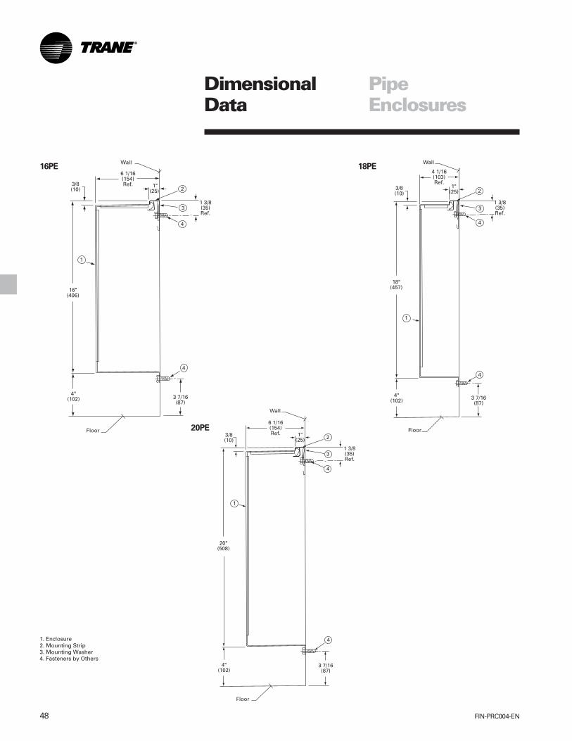
FIN-PRC004-EN48
DimensionalData
PipeEnclosures
1. Enclosure2. Mounting Strip3. Mounting Washer4. Fasteners by Others
16PE 18PE
20PE
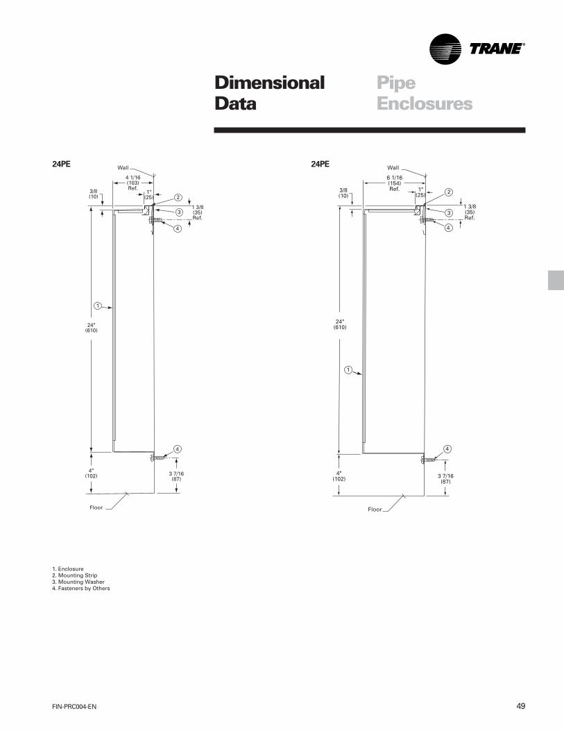
49FIN-PRC004-EN
DimensionalData
PipeEnclosures
1. Enclosure2. Mounting Strip3. Mounting Washer4. Fasteners by Others
24PE 24PE

FIN-PRC004-EN50
DimensionalData
Element, Enclosure And Cover Length —GeneralThe over-all length of an enclosure orcover, or of several joined together, is thesame as the ordering length. Over- alllength when an end panel is used is 1”(25 mm) longer than the ordering length.Over-all length when right and left endpanels are used is 2” (51 mm) longerthan the ordering length.
For wall-to-wall installations, use totallength to the nearest 6” (152 mm)increment below the actual wall-to-wallmeasurement. Enclosure extensionstelescope up to 4” (102 mm) to meet thewall. Access panels (6” (152 mm) or 12”(305 mm)) and 12” (305 mm) accesspanels with 5” x 6” (127 x 152 mm) sizeaccess door centered, provide easyaccess to valves and fittings and can beused for 6” (152 mm) or 12” (305 mm)runs to the wall.3/4” CA (19 mm) copper-aluminumelements are available in lengths of 1’(.305 m) through 8’ (2.4 m ) in 6” (0.15 m)increments. 1 1/4” (32 mm) steel or 1” (25mm) and 1 1/4” (32 mm) copper-aluminum elements are available inlengths of 1’ (.305 m) through 12’ (3.7 m)in 6” (0.15 m) increments. Cabinets areavailable in lengths of 2’ (.61 m) through8’ (2.4 m) in 6” (0.15 m) increments. TypeX covers in lengths of 2’ (.61 m) through8’ (2.4 m) in 6” (0.15 m) increments, 24”(610 mm) high cabinets in lengths of 2’(.61 m) through 8’ (2.4 m) in 6” (0.15 m)increments.
ElementsAssume an 18’ (5.5 m) of 1 1/4” (32 mm)steel, Series 52 element is required forcapacity needed. Unions will be used forjoining sections of the element alongwith supply and return connections atthe ends. Two 9’ (2.7 m) lengths ofelement will be required, with one jointbetween them. Total length of theinstalled assembly will be: 18’ (5.5 m)(element length) + union joint + lengthsof supply and return connections.
EnclosuresWith elements selected to meet capacityneeds, assume enclosures will beselected to cover elements and pipingconnections required. Since enclosuresare available in 6” (0.15 m) increments,19’ (2.7 m) will be used to cover theabove assembly. Two 6 1/2’ (2 m) and one6’ (1.8 m) enclosure, 6 brackets (2 perenclosure or 1 every three feet (.9m) willbe required. The overall length, includingright and left end panels, is 19’ (2.7 m) +2” (.05 m) = 19’ 2” (2.75 m).
Wall-To-Wall InstallationsTo make a wall-to-wall installation with atotal length of 20’ 4 1/2” (6.2 m), theenclosure selection would change. Inaddition to 20’ (6.1 m) of enclosure, two5” (127 mm) enclosure extensionswould be required to accommodate theodd 4 1/2” (114 mm) dimension. Four 5’(1.5 m) enclosures and eight enclosurebrackets would be needed.
Type X Covers And Type E CoversType X or Type E covers are normallyspecified to cover only the heatingelements. For an 18’ (5.5 m) of element,three 6’ (1.8 m) lengths of Type X or TypeE covers would be necessary. Type Xand Type E covers are supported at theback and bottom front by wall brackets.
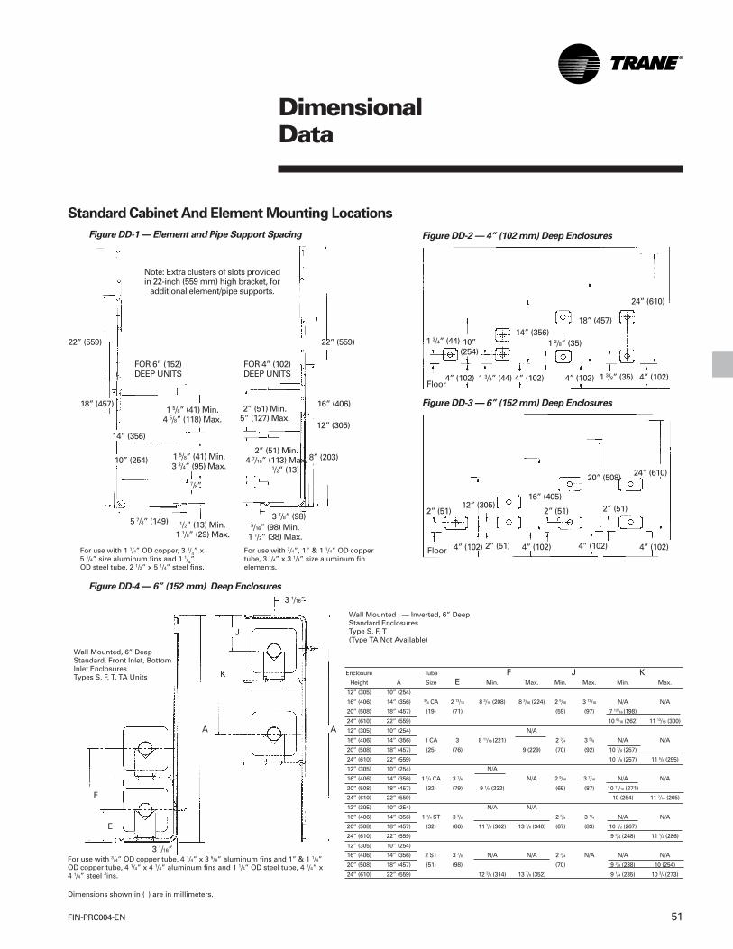
51FIN-PRC004-EN
Enclosure Tube F J KHeight A Size E Min. Max. Min. Max. Min. Max.
12” (305) 10” (254)
16” (406) 14” (356) 3/4 CA 2 13/16 8 3/16 (208) 8 3/16 (224) 2 5/16 3 13/16 N/A N/A
20” (508) 18” (457) (19) (71) (59) (97) 7 13/16 (198)
24” (610) 22” (559) 10 5/16 (262) 11 13/16 (300)
12” (305) 10” (254) N/A
16” (406) 14” (356) 1 CA 3 8 11/16 (221) 2 3/4 3 5/8 N/A N/A
20” (508) 18” (457) (25) (76) 9 (229) (70) (92) 10 7/8 (257)
24” (610) 22” (559) 10 1/8 (257) 11 5/8 (295)
12” (305) 10” (254) N/A
16” (406) 14” (356) 1 1/4 CA 3 1/8 N/A 2 9/16 3 7/16 N/A N/A
20” (508) 18” (457) (32) (79) 9 1/8 (232) (65) (87) 10 11/16 (271)
24” (610) 22” (559) 10 (254) 11 7/16 (265)
12” (305) 10” (254) N/A N/A
16” (406) 14” (356) 1 1/4 ST 3 3/8 2 5/8 3 1/4 N/A N/A
20” (508) 18” (457) (32) (86) 11 7/8 (302) 13 3/8 (340) (67) (83) 10 1/2 (267)
24” (610) 22” (559) 9 3/4 (248) 11 1/4 (286)
12” (305) 10” (254)
16” (406) 14” (356) 2 ST 3 7/8 N/A N/A 2 3/4 N/A N/A N/A
20” (508) 18” (457) (51) (98) (70) 9 3/8 (238) 10 (254)
24” (610) 22” (559) 12 3/8 (314) 13 7/8 (352) 9 1/4 (235) 10 3/4 (273)
DimensionalData
For use with 1 1/4” OD copper, 3 1/4” x5 1/4” size aluminum fins and 1 1/4”OD steel tube, 2 1/2” x 5 1/4” steel fins.
Wall Mounted , — Inverted, 6” DeepStandard EnclosuresType S, F, T(Type TA Not Available)
Figure DD-3 — 6” (152 mm) Deep Enclosures
Figure DD-2 — 4” (102 mm) Deep Enclosures
1 3/4” (44) 10”(254)
4” (102)Floor
4” (102)1 3/4” (44)
14” (356)
4” (102) 1 3/8” (35) 4” (102)
1 3/8” (35)
18” (457)
24” (610)
2” (51)
4” (102) 4” (102) 4” (102) 4” (102)
24” (610)
2” (51) 2” (51)12” (305)16” (405)
20” (508)
2” (51)Floor
Figure DD-4 — 6” (152 mm) Deep Enclosures
Figure DD-1 — Element and Pipe Support Spacing
22” (559)
16” (406)
12” (305)
Note: Extra clusters of slots providedin 22-inch (559 mm) high bracket, for
additional element/pipe supports.
22” (559)
18” (457)
FOR 6” (152)DEEP UNITS
FOR 4” (102)DEEP UNITS
8” (203)
14” (356)
10” (254)
5 7/8” (149) 3 7/8” (98)1/2” (13) Min.
1 1/8” (29) Max.9/16” (98) Min.
1 1/2” (38) Max.
7/8”
1 5/8” (41) Min.4 5/8” (118) Max.
1 5/8” (41) Min.3 3/4” (95) Max.
2” (51) Min.5” (127) Max.
2” (51) Min.4 7/16” (113) Max.
1/2” (13)
For use with 3/4”, 1” & 1 1/4” OD coppertube, 3 1/4” x 3 1/4” size aluminum finelements.
Standard Cabinet And Element Mounting Locations
F
E
3 1/16”
A
K
A
J
3 1/16”
Wall Mounted, 6” DeepStandard, Front Inlet, BottomInlet EnclosuresTypes S, F, T, TA Units
For use with 3/4” OD copper tube, 4 1/4” x 3 5/8” aluminum fins and 1” & 1 1/4”OD copper tube, 4 1/4” x 4 1/4” aluminum fins and 1 1/4” OD steel tube, 4 1/4” x4 1/4” steel fins.
Dimensions shown in ( ) are in millimeters.

FIN-PRC004-EN52
DimensionalData
TYPE X ENCLOSURE WALL HANGERAND CEILING HANGERType X enclosure ratings are 3 percentless than bare element ratings. Made of18-gauge (1.2 mm thickness) steel,cleaned, phosphatized and finished instandard prime baked enamel finish.Also available in choice of six bakedenamel finish colors.
TYPE X ENCLOSURE
B
Element Dimensions – Table DD-7
Ordering Length A
Finned Length2 1/2” (64) 1 1/4” (32) Copper-Aluminum
1 7/8” (48)
Ordering Length
Finned Length2 1/2” (64)
A
B
1 1/4” (32) Steel-Threaded
Type CS Enclosure — One Row ofElement, Ceiling Mounted – Table DD-10
1/2” (13) Dia. Mtg. Hole
C
D
AB
Type X Enclosure — Two Rows ofElements, Wall Mounted – Table DD-9
A
C
D
B
E
Type X Enclosure — One Row ofElement, Wall Mounted – Table DD-8
A
B
E
A
B
2 1/2” (64)
Ordering Length
Finned Length1 1/4” (32) Steel-Chamfered
2 1/2” (64)
Dimensions shown in ( ) are in millimeters

53FIN-PRC004-EN
Table DD-7 — Wall Fin Element Dimensions
3/4” (19) , 1” (25 mm) Or 1 1/4” (32) 1 1/4” (32)Copper Copper 1 1/4” (32)
Aluminum Aluminum SteelSeries Series Series
Dimension 40-50-58 40-50-58 52A 3 1/4” (83) 5 1/4” (133) 5 1/4” (133)B 3 1/4” (83) 3 1/4” (83) 2 1/2” (64)
Table DD-8
Enclosure Type 4x 5x3 1/4” 5 1/4”
Dimension (83) Fin (133) Fin4 5/8” 4 5/8”
A (117) (117)4” 6”
B (102) (152)3 ¼” 3 ¼”
E (83) (83)
Table DD-9
Enclosure Type 10x 12x 11x 13x3 1/4” 5 1/4”
Dimension (83) Fin (133) Fin10 5/8” 12 5/8” 10 5/8” 12 5/8”
A (270) (321) (270) (321)4” 4” 6” 6”
B (102) (102) (152) (152)2” 2” 3” 3”
C (51) (51) (76) (76)2 1/2” 2 1/2” 2 3/4” 2 3/4”
D (64) (64) (70) (70)6” 8” 6” 8”
E (152) (203) (152) (203)
Table DD-10
3 1/4” 5 1/4” 5 1/4”Dimension (83) CA (83) CA (133) S
3 5/8” 3 1/2” 3 1/4”A (92) (89) (83)
5 5/8” 5 1/2” 5”B (143) (140) (127)
3 7/8” 3 7/8” 3 7/8”C (98) (98) (98)
3 3/4” 5 3/4” 5 3/4”D (95) (146) (146)
CA — Copper Aluminum ElementS — All Steel Element
DimensionalData

FIN-PRC004-EN54
Options
Type T — Top Outlet Wall Fin EnclosureShown
Dirt Guard GasketFastens to back of the mountingstrip to prevent wall streaking.
Enclosure ExtensionsEnclosure extensions are designed toprovide additional length to standardenclosures on wall-to-wall installations orwhen additional length is required to fullycover elements and piping.
Special Purpose AccessoriesThese accessories can be used with TypeS, F, T and TA enclosures.
Sill extensions are used to extend the topof the cabinet back to the wall or windowsill. They can add up to 14 inches (356mm) of continuous surface to the top ofthe unit.
The sill extension is a separate anglepiece and is to be installed at the sametime as the mounting strip. The front 90-degree edge of the sill extension shouldbe butted up to the back side of themounting strip.Dimensions shown in ( ) are in millimeters.
1” (25)
1 3/4” (44)
1 3/4” (44)
2” (51 mm)
2” (51 mm)
Sill Extension
1/2” (13) To 14” (356)
2’ (.61 m) To 8’ (2.4 m)
2” (51)
End Panel
Enclosure
Inside Corner
Outside Corner
5”(127)

55FIN-PRC004-EN
Options
Access PanelTo gain access inside theWall Fin enclosure tovalves.
Access Panel with AccessDoor12” (305) long with a 5” (127)x 6” (152) access door to gainaccess to valves.
Mullion Channel
Table O-1 — Pilaster Assembly Dimensions
Dimension No. 5 No. 11 No. 17A 5” (127) 11” (279) 17” (432)B 5 1/8” (130) 111/8” (283) 171/8” (435)
Pilaster AssemblyPilaster covers effectively cover one, twoor three rows of piping and include twoL-shaped corner covers, support clips tohang the covers on the pilaster, onejoiner piece and rubber trim to gasket thepilaster cover joints at the enclosure.
Mullion channels are used on panel wallsor curtain walls where the wall studs (ormullions) are more than four feet apartand project into the room. Because of theweight of the wall fin unit and the lack ofstrength in the wall construction, mullionchannels are used to provide supportbetween the wall studs. The channels fillthe space between the wall fin cabinetand the panel wall or curtain wall.
Enclosure
Access Door
End Panel
Corner Section
End View ShownMounted on Wall.
Dimensions shown in ( ) are in millimeters.
Pilaster Joiner Piece
3 3/4”(95)
4” (102)3 13/16”
(97)
A
B
3 3/4” (95)
12” (305)
3 3/4”(95)
12” (305)
6” (152) Or 12” (305) 12”(305)
5” (127) x 6” (152)ACCESS DOOR
ORDERING LENGTH10’ MAX.
(3 m) 4 1/8” (105 mm)
1/4” (6 mm) To 2” (51 mm)

FIN-PRC004-EN56
MechanicalSpecifications
GeneralThe contractor shall furnish and installTrane wall fin as shown on the plans.Ratings shall be IBR approved. Unitsshall be installed in a neat andworkmanlike manner in accordance withspecifications and manufacturerrecommendations.
Heating ElementsElement types, as indicated on plans,shall have integral fin collars which spacethe fins and provide fin-to-tube surfacefirmly bonded by mechanical expansionof the tube to ensure durability, eliminatenoise from loose fins and assureperformance at cataloged ratings.Elements shall be positively positionedfront-to-back, with provisions for silenthorizontal expansion and contraction.
EnclosuresEnclosures shall be as scheduled on theplans, constructed of 16-gauge 1.5 mmthickness, or optional 14-gauge 1.9thickness steel and shall mount into acontinuous roll-formed captive channelmounting strip which permits hinge-typemounting and access at the top andinvisible fastening onto rigidized, 14-gauge (1.9 mm thickness) steel enclosurebrackets at the bottom. Enclosurebrackets shall be spaced at not morethan four-foot (1.2 m) intervals.
Front panels shall be individuallyremovable to facilitate cleaning, servicingor replacement. All accessories shallfasten to the enclosure assembly in amanner which prevents contact with theback wall during installation.
Cabinet air outlets of stamped sheetmetal or the manufacturer shall supply abar type extruded aluminum grille toprovide strong linear styling.
Type 3E and 4E enclosures shall be 16-gauge (1.5 mm thickness) or 14-gauge(1.9 mm thickness) steel. Type E3 and E3-2W enclosures shall be 16-gauge steel.
Type X and CS enclosures shall be 18-gauge (1.2 mm) steel with stampedsquare outlet openings. Enclosures tohave smooth edges on all sides.
Pipe EnclosuresPipe enclosures shall be as scheduled onthe plans, constructed of solid (16-gauge1.5 mm thickness) steel or optional (14-gauge 1.9 mm thickness) steel and shallmount into a continuous roll-formedcaptive channel mounting strip whichpermits hinge-type mounting and accessat the top and fastening at the bottomwith visible fasteners by others. Frontpanels shall be solid metal top andbottom, one piece wrap around and beindividually removable to facilitateservicing or replacement.
Standard FinishAll enclosures, mounting strips andaccessories are cleaned, phosphatizedand painted with one coat of prime,baked enamel finish as standard.
Other Color FinishesOther baked-on enamel color finishesavailable as standard shall be chosenfrom Color Selection Chart UNT-S-10.
Accessories And OptionsEnd panels, inside and outside cornersand enclosure extensions shall be die-formed and shall lock to enclosureassembly without visible fasteners.
Dampers (hydronic units only) shallreduce heating capacity up to 70 percentwhen closed and shall be factorymounted on the element. The control
dial shall be jam-proof and have amechanism which prevents damage tothe dial or damper. As an alternate, thecontractor shall furnish and install controlvalves and appropriate access.
Access panels shall be installed wherevalves, balancing cocks or traps areindicated on the plans.
The 3E and 4E wall mounted elementcovers (16-gauge (1.5 mm thickness) or14-gauge (1.9 mm thickness) steel) andaccessories shall be provided asindicated on the plans. (Accessoriesrequire visible fasteners.)
Type E3 and E3-2W three-sided pedestalmounted element covers andaccessories shall be provided whereshown on plan. (Enclosures of 16-gauge(1.5 mm) steel only.) (Accessories requirevisible fasteners.)
Back panels, sill extensions, mullionchannel, stamped sheet metal, front airinlet grilles, tamperproof screwassemblies and pilaster covers shall beprovided where indicated on plans. Toprevent dirt streaking, contractor shalleither apply dirt guard gasket tomounting strip or caulk along top ofmounting strip.
Bottom Air Inlet GrilleThe bottom air inlet grille shall be ofstamped sheet metal and part of thefront panel (one piece) installs into themounting strip at the top and attaches tothe wall at the bottom with visiblefasteners by others. Bottom air inlet grilleconfigurations use Type E wall bracketsfor installation of the heating element.

57FIN-PRC004-EN
MechanicalSpecifications
Type E3A-1W and E3A-2Wwith Aluminum Air OutletGrilles
SpecificationsNatural convection with extrudedaluminum air out grille(s). Pedestal floormounted wall fin shall be furnished tomeet the specified capacity. Enclosuresetc., heating elements and accessoriesshall be installed in accordance with themanufacture’s recommendations.
TYPE - E3A-1W - EnclosureFloor mounted Type E3A-1W single wideelement enclosure has continuousaluminum air outlet grilles made ofheavy extruded aluminum, finished in anetched and clear 204-R1 hard anodizedfinish. E3A-1W cover of 16 gauge (1.5mm), or optional 14 gauge (1.9 mm) steelwith wall sleeve at each joint for panel topanel joining, and alignment. Enclosuremounted on U-shaped 0.1875” thick (4.8mm) phosphatized steel enclosure/pedestal/element bracket assemblypainted black. Two ball bearing cradleguides with slide cradle are provided foreach bracket to allow the element toexpand and contract without strain ornoise. Enclosure height of 6 3/4”(171 mm) with overall installed heightfrom floor to top of enclosure of 10 3/4”(273 mm). Enclosure depth of 6 1/16”(154 mm) furnished in lengths of 2 feet(.61 m) through 8 feet (2.4 m) in 6”(0.1524 m) increments.
TYPE - E3A-2W - EnclosureFloor mounted Type E3A-2W doublewide element enclosure havecontinuous aluminum air outlet grillesmade of heavy extruded aluminum,finished in an etched and clear 204-R1hard anodized finish. E3A-2W cover of 16gauge (1.5 mm), or optional 14 gauge(1.9 mm) steel with wall sleeve at eachjoint for panel to panel joining, andalignment. Enclosure mounted on U-shaped 0.1875” thick (4.8 mm)phosphatized steel enclosure/pedestal/element bracket assembly painted black.Two ball bearing cradle guides with slidecradle are provided for each bracket toallow the element to expand andcontract without strain or noise.Enclosure height of 6 3/4” (171 mm) withoverall installed height from floor to topof enclosure of 10 3/4” (273 mm).Enclosure depth of 10 5/16” (262 mm)furnished in lengths of 2 feet (.61 m)through 8 feet (2.4 m) in 6” (0.1524 m)increments.
Accessories4” (102 mm) 6” (152 mm) or 8 3/8” (213mm) wide wall sleeves required at eachjoint for panel to panel alignment areunderlapping reveal type.
3” end panels, 8 3/8” (213 mm) wide wallsleeve with access door, 90 or 135degree inside corners, 90 or 135 degreeoutside corners fabricated of 18 gauge(1.2 mm) steel are underlapping revealtype.
Slide DamperSlide damper available for type E3A-1Wenclosure only and is factory installed onthe extruded aluminum air outlet grille.The slide damper assembly consisting oftwo integrated extruded aluminum clearanodized grille plates provide airdischarge control by front to backpositioning. Requires no mechanicalactuating parts.

FIN-PRC004-EN58
MechanicalSpecifications
Color FinishAll enclosures, back plate/mounting stripand accessories shall be painted with abaked-on commercial primer paint asstandard. Optional baked-on enamelcolor finishes shall be available.
Color Options Baked-on enamel colorfinish shall be chosen from ColorSelection Chart UNT-S-10 May 1994.
• Prime (Standard)Optional Colors
• Deluxe Beige• Cameo White• Soft Dove• Driftwood Grey• Stone Grey• Rose Mauve
Heating Elements
• 3/4” CA (19 mm)(Copper Tube-Aluminum Fin)The heating elements shall beconstructed of seamless copper tubingmechanically expanded into aluminumfins. One tube end swaged for end-to-end joining. 4 1/4” x 3 5/8” (108 mm x 92mm) size fins x .020” (.51 mm) finthickness for maximum heat transfer.— Fin spacing of 40 fins per foot
(131 fins per m).— Fin spacing of 50 fins per foot
(164 fins per m).
• 1” CA (25 mm)(Copper Tube-Aluminum Fin)The heating elements shall beconstructed of seamless copper tubingmechanically expanded into aluminumfins. One tube end swaged for end-to-end joining. 4 1/4” x 4 1/4” (108 mm x108 mm) size fins x .020” (.51 mm) finthickness for maximum heat transfer.— Fin spacing of 40 fins per foot
(131 fins per m).— Fin spacing of 50 fins per foot
(164 fins per m).
• 1 1/4” CA (32 mm)(Copper Tube-Aluminum Fin)The heating elements shall beconstructed of seamless copper tubingmechanically expanded into aluminumfins. One tube end swaged for end-to-end joining. 4 1/4” x 4 1/4” (108 mm x108 mm) size fins x .020” (.51 mm) finthickness for maximum heat transfer.— Fin spacing of 40 fins per foot
(131 fins per m).— Fin spacing of 50 fins per foot
(164 fins per m).
• 1 1/4” Steel (32 mm)(Steel Tube-Steel Fins)The heating elements shall beconstructed of condenser tubingmechanically expanded into steel fins.Tube ends shall be threaded andfurnished with NPT threads. 4 1/4” x4 1/4” (108 mm x 108 mm) size fins x.032” (.81 mm) fin thickness formaximum heat transfer.— Fin spacing of 40 fins per foot
(131 fins per m).— Fin spacing of 32 fins per foot
(105 fins per m).
Element Lengths3/4” CA (19 mm) elements shall beprovided in 1’ (.3048 m) thru 8’ (2.44 m)lengths in 6” (.1524 m) increments.
1” CA (25 mm) & 1 1/4” CA (32 mm)elements shall be provided in 1’ (.3048m) thru 12’ (3.66 m) lengths in 6” (.1524m) increments.
1 1/4” Steel (32 mm) elements shall beprovided in 1’ (.3048 m) thru 12’ (3.66 m)lengths in 6” (.1524 m) increments.
Heating Elements With 3 1/4” x 3 1/4” (83x 83 mm) Size Fins
• 3/4“ (19 mm) CA(Copper Tube- Aluminum Fin)The heating elements shall be copper-aluminum constructed of seamlesscopper tubing mechanically expandedinto aluminum fins. One tube endswaged for end-to-end joining. 3 1/4”x 3 1/4” (83 mm x 83 mm) size fins with
fin spacing of 40, 50 or 58 fins per foot(132, 165 or 191 fins per meter), areprovided with full collars for uniformspacing and maximum thermalcontact. Formed top and bottom edgesprovide strength. Two louversprovided on each fin for maximum airflow efficiency. Elements shall beavailable in 1 foot (.3048 m) through8 foot (2.44 m) lengths in 6 inch(.1524 m) increments.
• 1” (25 mm) CA(Copper Tube- Aluminum Fin)Copper-Aluminum elementsconstructed of seamless copper tubingmechanically expanded into aluminumfins. One tube end swaged for end-to-end joining. 3 1/4” x 3 1/4” (83 mm x83 mm) size fins with fin spacing of 40,50 or 58 fins per foot (132, 165 or 191fins per meter), are provided with fullcollars for uniform spacing andmaximum thermal contact. Formedtop and bottom edges providestrength. Two louvers provided oneach fin for maximum air flowefficiency. Elements shall be availablein 1 foot (.3048 m) through 12 foot(3.66 m) lengths in 6 inch (.1524 m)increments.
• 1 1/4” (32 mm) CA(Copper Tube- Aluminum Fin)Copper-Aluminum elementsconstructed of seamless copper tubingmechanically expanded into aluminumfins. One tube end swaged for end-to-end joining. 3 1/4” x 3 1/4” (83 mm x83 mm) size fins with fin spacing of 40,50 or 58 fins per foot (132, 165 or 191fins per meter), are provided with fullcollars for uniform spacing andmaximum thermal contact. Formedtop and bottom edges providestrength. Two louvers provided oneach fin for maximum air flowefficiency. Elements shall be availablein 1 foot (.3048 m) through 12 foot(3.66 m) lengths in 6 inch (.1524 m)increments.

59FIN-PRC004-EN
MechanicalSpecifications
Model E3A-2W
Model E3A-1W

FIN-PRC004-EN60
MechanicalSpecifications
Recommended Schedule and InstallationProcedure1.Layout job selecting enclosure lengths
with appropriate wall sleeve at each joint.Space enclosures to suit. At end of runuse wall sleeve or 3” (76 mm) end to suitjob.
2.Layout pedestal bracket assembly so thecenter-line is 7 1/2” (191 mm) from eachend of enclosure to avoid interferencewith enclosure gussets. Locate 1 pedestalbracket assembly at center of enclosureslonger than 4 ft. (1.22 m).
NOTE: Schedule enclosures to overlapaccessories 1”-3” (25-76 mm) except ends1”-2” (25-51 mm) with access door overlapmax. 1” (25 mm).
Slide Damper (SD) — OptionalThe slide damper assembly consisting of twointegrated extruded aluminum clear anodizedgrille plates provide air discharge control byfront to back positioning which requires nomechanical actuating parts.
Note: Fasten accessory with 6 S.M. Screwthrough solid part of grille. Drill 37 (104)holes into accessory when in position.
One wide enclosure shown.
Installation Layout for Pedestal Mount E3A-1W One Wide Enclosure
Wall Sleeve Support(Slotted For PipingWhere Specified)
Wall Sleeve 4” (102 mm)or 8 3/8” (213 mm)
(Access Door Optional8 3/8” (213 mm) Only)
Corner — Inside and/orOutside Short Leg
Dimension 8 3/8” (213 mm)
Cradle
Pedestal Bracket Assembly
Enclosure Assembly — Typical
3” (76 mm) End Assembly
Wall Sleeve in RunAt Each Joint

61FIN-PRC004-EN
MechanicalSpecifications
Table M-1 — Ratings, Type E3A-1W Enclosures With Copper/Aluminum Elements With 3 1/4” x 3 1/4” (83 mm x 83 mm) Size Fins
Steam Capacity Hot Water CapacityPer Ft.-1 Psi at 65°F Air Btu/Hr./Ft. — At 65°F Air, Average Water TemperaturePer Meter - 6.895 kPa Watts/Meter — At 18.3°C Air, Average Water Temperature
at 18.3°C Air
Install. 220°F 210°F 200°F 190°F 180°F 170°F 160°F 150°F140°F130°F120°F 110°F 100°FFin Series Height EDR 104°C 99°C 93°C 88°C 82°C 77°C 71°C 66°C 60°C 54°C 49°C 43°C 38°C
Per Foot Inches Sq. Ft. Btu/Hr./Ft. IBR Factor — Steam to Hot WaterElement Per Meter Tiers Encl. mm Sq. M Watts/Meter 1.05 0.95 0.86 0.78 0.69 0.61 0.53 0.45 0.40 0.33 0.26 0.20 0.15
3/4” CA19 mm
Copper Tube 40 1 E3A-1W 9 3/16 4.04 970 1020 920 835 755 670 590 515 435 390 320 250 195 145Alum. Fins 131 m 233 43 933 981 885 803 726 644 567 495 418 375 308 240 188 139
Fins 3 1/4” x 3 1/4” 50 1 E3A-1W 9 3/16 4.48 1075 1130 1020 925 840 740 655 570 485 430 355 280 215 16083 x 83 mm 164 m 233 48 1030 1090 981 889 808 712 630 548 466 413 341 269 207 154
Thickness .0135” 58 1 E3A-1W 9 3/16 4.75 1140 1200 1085 980 890 785 695 605 515 455 375 295 230 170.34 mm 190 m 233 51 1100 1150 1040 942 856 755 668 582 495 438 361 284 221 163
1” CA25 mm
Copper Tube 40 1 E3A-1W 9 3/16 4.04 970 1020 920 835 755 670 590 515 435 390 320 250 195 145Alum. Fins 131 m 233 43 933 981 885 803 726 644 567 495 418 375 308 240 188 139
Fins 3 1/4” x 3 1/4” 50 1 E3A-1W 9 3/16 4.43 1065 1120 1010 915 830 735 650 565 480 425 350 275 215 16083 x 83 mm 164 m 233 48 1020 1080 971 880 798 707 625 543 462 409 337 264 207 154
Thickness .0135” 58 1 E3A-1W 9 3/16 4.66 1120 1175 1065 965 875 775 685 595 505 450 370 290 225 170.34 mm 190 m 233 50 1080 1130 1020 928 841 745 659 572 486 433 356 279 216 163
1 1/4” CA32 mm
Copper Tube 40 1 E3A-1W 9 3/16 4.08 980 1030 930 840 765 675 600 520 440 390 325 255 195 145Alum. Fins 131 m 233 44 942 990 894 808 736 649 577 500 423 375 313 245 188 139
Fins 3 1/4” x 3 1/4” 50 1 53A-1W 9 3/16 4.43 1065 1120 1010 915 830 735 650 565 480 425 350 275 215 16083 x 83 mm 164 m 233 48 1020 1080 971 880 798 707 625 543 462 409 337 264 207 154
Thickness .0135” 58 1 E3A-1W 9 3/16 4.62 1110 1165 1055 955 865 765 680 590 500 445 365 290 220 165.34 mm 190 m 233 50 1070 1120 1010 918 832 736 654 567 481 428 351 279 212 159
IBR does not have procedure for rating pedestal mounted enclosures.Dimensions in bold indicate metric units.
Metric Conversions
1 Psi = 6.895 kPa (Kilo Pascals) at 65°F Air = 18.3°C Air
Sq. Ft. EDR at 1 Psi (6.895 kPa) at 65°F Air (18.3°C) Air x 240 BTU = Total BTU’s (Watts)
1 BTU/HR. = 0.2931 Watts
1 Foot = 0.3048 Meters - 1 Meter = 3.2808 Feet
1 BTU/HR/FT = 0.9616 Watts/Meter
10.7639 Sq. Feet = 1 Square Meter
1 Lbs = 0.4536 Kg (Kilograms)
1 Inch = 25.4 mm (Millimeters)
Capacities based Finned Length at a Water Velocity of 3 feet per second or 0.9144 Meter per second or greater

FIN-PRC004-EN62
MechanicalSpecifications
Table M-2 — Ratings, Type E3A-1W Enclosure With Copper Aluminum Elements
Steam CapacityPer Ft.-1 Psi at 65°F Air Hot Water (Avg.)
Tube Encl. Mtg. Per Meter - 6.895 kPa 200°F 190°F 180°F 170°F 160°F 150°F 140°F 130°FSize Fin Fin Fin Height Height at 18.3°C Air 93°C 88°C 82°C 77°C 71°C 66°C 60°C 54°C
Inches Catalog Size Per Ft. Thickness Inches 1-Row Inches Btu/Hr./Ft. Factor(mm) Desig. In. (mm) (Per M) In. (mm) (mm) Wide (mm) Watts/Meter .86 .78 .69 .61 .53 .45 .40 .33
3/4 3CA4340 4 1/4 x 3 5/8 40 .020 6 3/4 1-W 10 3/4 1190 1020 930 820 730 630 540 480 390(19) (108 x 92) (131) (.51) (171) (273) 1140 981 894 789 702 606 519 462 375
3/4 3CA4350 4 1/4 x 3 5/8 50 .020 6 3/4 1-W 10 3/4 1290 1110 1010 890 790 680 580 520 430(19) (108 x 92) (164) (.51) (171) (273) 1240 1070 971 856 760 654 558 500 413
1 1CA4440 4 1/4 Sq. 40 .020 6 3/4 1-W 10 3/4 1440 1240 1120 990 880 760 650 580 480(25) (108) Sq. (131) (.51) (171) (273) 1380 1190 1080 952 846 731 625 558 462
1 1CA4450 4 1/4 Sq. 50 .020 6 3/4 1-W 10 3/4 1480 1270 1150 1020 990 780 670 590 490(25) (108) Sq. (164) (.51) (171) (273) 1420 1220 1110 981 952 750 644 567 471
1 1/4 4CA4440 4 1/4 Sq. 40 .020 6 3/4 1-W 10 3/4 1340 1150 1050 920 820 710 600 540 440(32) (108) Sq. (131) (.51) (171) (273) 1290 1110 1010 885 789 683 577 519 423
1 1/4 4CA4450 4 1/4 Sq. 50 .020 6 3/4 1-W 10 3/4 1470 1260 1150 1010 900 780 660 590 490(32) (108) Sq. (164) (.51) (171) (273) 1410 1210 1110 971 865 750 635 567 471
Table M-3 — Ratings, Type E3A-1W Enclosure With Steel Elements
Steam CapacityPer Ft.-1 Psi at 65°F Air Hot Water (Avg.)
I.P.S. Encl. Mtg. Per Meter - 6.895 kPa 200°F 190°F 180°F 170°F 160°F 150°F 140°F 130°FSize Fin Fin Fin Height Height at 18.3°C Air 93°C 88°C 82°C 77°C 71°C 66°C 60°C 54°C
Inches Catalog Size Per Ft. Thickness Inches 1-Row Inches Btu/Hr./Ft. Factor(mm) Desig. In. (mm) (Per M) In. (mm) (mm) Wide (mm) Watts/Meter .86 .78 .69 .61 .53 .45 .40 .331 1/4 *4ST4432 4 1/4 Sq. 32 0.32 6 3/4 1-W 10 3/4 1130 970 880 780 690 600 510 450 370(32) (108) Sq. (105) (.81) (171) (273) 1090 933 846 750 664 577 490 433 356
1 1/4 *4ST4440 4 1/4 Sq. 40 .032 6 3/4 1-W 10 3/4 1240 1070 970 860 760 660 560 500 410(32) (108) Sq. (131) (.81) (171) (273) 1190 1030 933 827 731 635 538 481 394
*Note: NPT threads furnished on steel elements. Please use domestic fittings for proper installation.

63FIN-PRC004-EN
MechanicalSpecifications
Table M-5 — Ratings, Type E3A-2W Double Wide Pedestal Enclosure With Steel Elements
Steam CapacityPer Ft.-1 Psi at 65°F Air Hot Water (Avg.)
I.P.S. Encl. Mtg. Per Meter - 6.895 kPa 200°F 190°F 180°F 170°F 160°F 150°F 140°F 130°FSize Fin Fin Fin Height Height at 18.3°C Air 93°C 88°C 82°C 77°C 71°C 66°C 60°C 54°C
Inches Catalog Size Per Ft. Thickness Inches 2-Rows Inches Btu/Hr./Ft. Factor(mm) Desig. In. (mm) (Per M) In. (mm) (mm) Wide (mm) Watts/Meter .86 .78 .69 .61 .53 .45 .40 .331 1/4 *4ST4432 4 1/4 Sq. 32 .032 6 3/4 2-W 10 3/4 1550 1330 1210 1070 950 820 700 620 510(32) (108) Sq. (105) (.81) (171) (273) 1490 1280 1160 1030 914 789 673 596 490
1 1/4 *4ST4440 4 1/4 Sq. 40 .032 6 3/4 2-W 10 3/4 1900 1630 1480 1310 1160 1010 860 760 630(32) (108) Sq. (131) (.81) (171) (273) 1830 1570 1420 1260 1120 971 837 731 606
*Note: NPT threads furnished on steel elements. Please use domestic fittings for proper installation.
Dimensions in bold indicate metric units.
Table M-4 — Ratings, Type E3A-2W Double Wide Pedestal Enclosure With Copper Aluminum Elements
Steam CapacityPer Ft.-1 Psi at 65°F Air Hot Water (Avg.)
Tube Encl. Mtg. Per Meter - 6.895 kPa 200°F 190°F 180°F 170°F 160°F 150°F 140°F 130°FSize Fin Fin Fin Height Height at 18.3°C Air 93°C 88°C 82°C 77°C 71°C 66°C 60°C 54°C
Inches Catalog Size Per Ft. Thickness Inches 2-Rows Inches Btu/Hr./Ft. Factor(mm) Desig. In. (mm) (Per M) In. (mm) (mm) Wide (mm) Watts/Meter .86 .78 .69 .61 .53 .45 .40 .33
3/4 3CA4340 4 1/4 x 3 5/8 40 .020 6 3/4 2-W 10 3/4 1820 1570 1420 1260 1110 960 820 730 600(19) (108 x 92) (131) (.51) (171) (273) 1750 1510 1360 1210 1070 923 789 702 577
3/4 3CA4350 4 1/4 x 3 5/8 50 .020 6 3/4 2-W 10 3/4 1980 1700 1540 1370 1210 1050 890 790 650(19) (108 x 92) (164) (.51) (171) (273) 1900 1640 1480 1320 1160 1010 856 760 625
1 1CA4440 4 1/4 Sq. 40 .020 6 3/4 2-W 10 3/4 2450 2110 1910 1690 1490 1300 1100 980 810(25) (108) Sq. (131) (.51) (171) (273) 2360 2030 1840 1620 1430 1250 1060 942 779
1 1CA4450 4 1/4 Sq. 50 .020 6 3/4 2-W 10 3/4 2540 2180 1980 1750 1550 1350 1140 1020 804(25) (108) Sq. (164) (.51) (171) (273) 2440 2100 1900 1680 1490 1300 1100 981 808
1 1/4 4CA4440 4 1/4 Sq. 40 .020 6 3/4 2-W 10 3/4 2290 1970 1790 1580 1400 1210 1030 920 760(32) (108) Sq. (131) (.51) (171) (273) 2200 1890 1720 1520 1350 1160 990 885 731
1 1/4 4CA4450 4 1/4 Sq. 50 .020 6 3/4 2-W 10 3/4 2530 2180 1970 1750 1540 1340 1140 1010 830(32) (108) Sq. (164) (.51) (171) (273) 2430 2100 1890 1680 1480 1290 1100 971 798

FIN-PRC004-EN64
MechanicalSpecifications
Type DS Double Slope
Wall Mounted
SpecificationsNatural convection double slope wallmounted. Wall fin shall be furnished tomeet the specified capacity. Enclosuresetc., heating elements and accessoriesshall be installed in accordance with themanufacture’s recommendations.
TYPE - DS - Double Slope EnclosureMountingHydronic Type DS Double Slope Wall Finenclosures shall be wall mounted 40”(1016 mm) minimum above the floorlevel to obtain catalog capacities.
Type DS double slope enclosurefurnished with louvered air inlet andoutlet grilles of one piece full wrap-around design for completeengagement with the wall to preventaccess to the inside of the enclosure.Enclosures fabricated from 16 gauge (1.5mm thickness) steel for strength anddurability. Optional 18 gauge (1.2 mmthickness) steel is available. All enclosurepanels manufactured with interlockingslip joints provides a positive snap fitbetween enclosures. Internal 14 gauge
(1.9 mm) gussets provide additionalstrength and rigidity. A full back plate(one piece) is furnished with a formedmounting channel at the top of the backplate for installation of the elementbrackets which are mounted to the topinside form of the back plate providingproper positioning of each bracket andengages the top of the enclosure. Theenclosures air inlet are provided with a7/16” (11 mm) 90 degree turn down forfastening the bottom of the enclosurepanel to the bottom form of thebackplate to securely lock it in place.Enclosure depth of 5 5/16” (135 mm)furnished in heights of 19 1/2” (495 mm),25 1/2” (648 mm) and 29 1/2” (749 mm).Enclosures available in 2 feet (0.61 m)through 8 feet (2.4 m) in 6” (0.15 m)increments.
Enclosure brackets with adjustableelement supports are die-formedchannel type construction to providerigid support of the heating element.Nickel chromium plated ball bearingsencased in a nylon insert with galvanizedelement cradles provides for silent glideoperation during expansion andcontraction of the heating element.
DampersFully modulating knob operated andtamper resistant dampers field installedon the air inlet grille and gussets forpositive temperature control.
AccessoriesEnd caps 3” (76 mm) wide in left andright hand configurations.
End caps 8 3/8” (213 mm) wide withaccess door in left and right handconfigurations.
4” (102 mm) and 8 3/8” (213 mm) widewall sleeves.
8 3/8” (213 mm) wide wall sleeve withaccess door.
90 degree inside and outside corners.
All accessories die-formed with flange attop to engage behind the back plate.

65FIN-PRC004-EN
MechanicalSpecifications
Color FinishAll enclosures, back plate/mounting stripand accessories shall be painted with abaked-on commercial primer paint asstandard. Optional baked-on enamelcolor finishes shall be available.
Color Options Baked-on enamel colorfinish shall be chosen from ColorSelection Chart UNT-S-10 May 1994.
• Prime (Standard)Optional Colors
• Deluxe Beige• Cameo White• Soft Dove• Driftwood Grey• Stone Grey• Rose Mauve
Heating Elements
• 3/4” CA (19 mm)(Copper Tube-Aluminum Fin)The heating elements shall beconstructed of seamless copper tubingmechanically expanded into aluminumfins. One tube end swaged for end-to-end joining. 4 1/4” x 3 5/8” (108 mm x92 mm) size fins x .020” (.51 mm) finthickness for maximum heat transfer.— Fin spacing of 40 fins per foot
(131 fins per m).— Fin spacing of 50 fins per foot
(164 fins per m).
• 1” CA (25 mm)(Copper Tube-Aluminum Fin)The heating elements shall beconstructed of seamless copper tubingmechanically expanded into aluminumfins. One tube end swaged for end-to-end joining. 4 1/4” x 4 1/4” (108 mm x108 mm) size fins x .020” (.51 mm) finthickness for maximum heat transfer.— Fin spacing of 40 fins per foot
(131 fins per m).— Fin spacing of 50 fins per foot
(164 fins per m).
• 1 1/4” CA (32 mm)(Copper Tube-Aluminum Fin)The heating elements shall beconstructed of seamless copper tubingmechanically expanded into aluminumfins. One tube end swaged for end-to-end joining. 4 1/4” x 4 1/4” (108 mm x
108 mm) size fins x .020” (.51 mm) finthickness for maximum heat transfer.— Fin spacing of 40 fins per foot
(131 fins per m).— Fin spacing of 50 fins per foot
(164 fins per m).
• 1 1/4” Steel (32 mm)(Steel Tube-Steel Fins)The heating elements shall beconstructed of condenser tubingmechanically expanded into steel fins.Tube ends shall be threaded andfurnished with NPT threads. 4 1/4” x4 1/4” (108 mm x 108 mm) size fins x.032” (.81 mm) fin thickness formaximum heat transfer.— Fin spacing of 40 fins per foot
(131 fins per m).— Fin spacing of 32 fins per foot
(105 fins per m).
Element Lengths3/4” CA (19 mm) elements shall beprovided in 1’ (.3048 m) thru 8’ (2.44 m)lengths in 6” (1.6 m) increments.
1” CA (25 mm) & 1 1/4” CA (32 mm)elements shall be provided in 1’(.3048 m) thru 12’ (3.66 m) lengths in 6”(.152 m) increments.
1 1/4” Steel (32 mm) elements shall beprovided in 1’ (.3048 m) thru 12’ (3.66 m)lengths in 6” (.152 m) increments.
Heating Elements With 3 1/4” x 3 1/4”(83 x 83 mm) Size Fins
• 3/4“ (19 mm) CA(Copper Tube- Aluminum Fin)The heating elements shall be copper-aluminum constructed of seamlesscopper tubing mechanically expandedinto aluminum fins. One tube endswaged for end-to-end joining. 3 1/4” x3 1/4” (83 mm x 83 mm) size fins withfin spacing of 40, 50 or 58 fins per foot(132, 165 or 191 fins per meter), areprovided with full collars for uniformspacing and maximum thermal
contact. Formed top and bottom edgesprovide strength. Two louversprovided on each fin for maximum airflow efficiency. Elements shall beavailable in 1 foot (.3048 m) through8 foot (2.44 m) lengths in 6 inch(.1524 m) increments.
• 1” (25 mm) CA(Copper Tube- Aluminum Fin)Copper-Aluminum elementsconstructed of seamless copper tubingmechanically expanded into aluminumfins. One tube end swaged for end-to-end joining. 3 1/4” x 3 1/4” (83 mm x83 mm) size fins with fin spacing of 40,50 or 58 fins per foot (132, 165 or 191fins per meter), are provided with fullcollars for uniform spacing andmaximum thermal contact. Formedtop and bottom edges providestrength. Two louvers provided oneach fin for maximum air flowefficiency. Elements shall be availablein 1 foot (.3048 m) through 12 foot(3.66 m) lengths in 6 inch (.1524 m)increments.
• 1 1/4” (32 mm) CA(Copper Tube- Aluminum Fin)Copper-Aluminum elementsconstructed of seamless copper tubingmechanically expanded into aluminumfins. One tube end swaged for end-to-end joining. 3 1/4” x 3 1/4” (83 mm x83 mm) size fins with fin spacing of 40,50 or 58 fins per foot (132, 165 or 191fins per meter), are provided with fullcollars for uniform spacing andmaximum thermal contact. Formedtop and bottom edges providestrength. Two louvers provided oneach fin for maximum air flowefficiency. Elements shall be availablein 1 foot (.3048 m) through 12 foot(3.66 m) lengths in 6 inch (.1524 m)increments.

FIN-PRC004-EN66
MechanicalSpecifications
Wall
5 5/16”(135 mm)
5/8”(16 mm)
5 3/16” (132 mm)(14) Louv.
MIN19 1/16” (484 mm)15 1/16” (383 mm)9 1/16” (230 mm)
MAX20 5/16” (516 mm)16 5/16” (414 mm)10 5/16” (262 mm)
6”(152 mm)
DS 29 — 1 & 2 TierDS 25
DS 19 — 1 Tier Only
29 1/2” (749 mm)
25 1/2” (658 mm)
19 1/2” (495 mm)
5 3/16” (132 mm)(14) Louv.
5/8”(16 mm)
7/16” (11 mm)
18 3/4”(476 mm)
14 3/4”(375 mm)
8 3/4”(222 mm)
29 7/8” (759 mm)
25 7/8” (658 mm)
19 7/8” (505 mm)
2 31/32”(74 mm)
2 11/16”(68 mm)
Model DS Double Slope EnclosuresFinned Tube Radiation
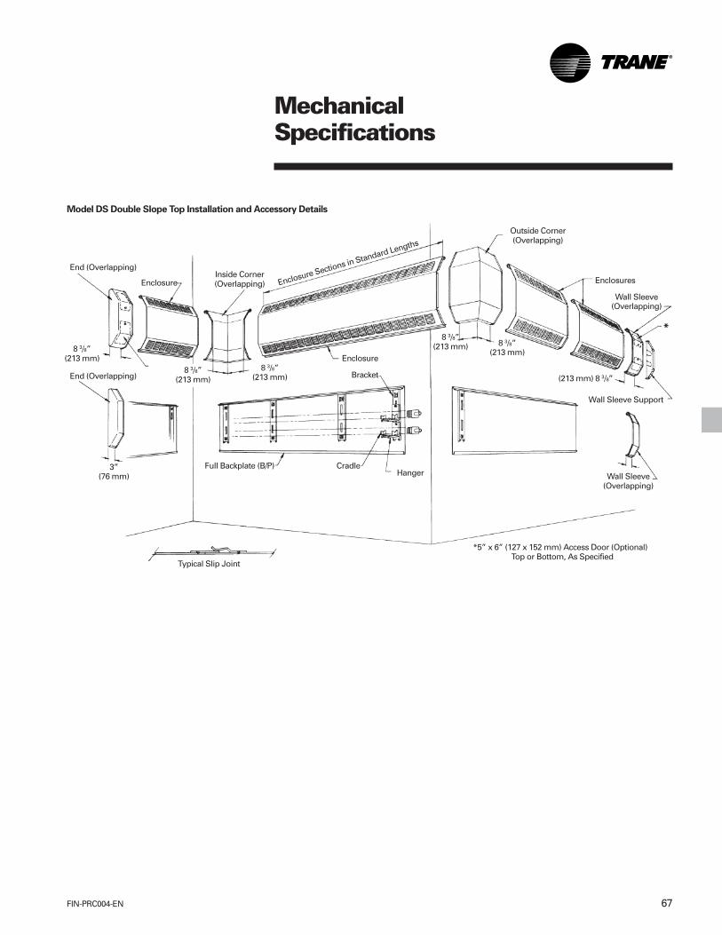
67FIN-PRC004-EN
MechanicalSpecifications
Model DS Double Slope Top Installation and Accessory Details
End (Overlapping)
Enclosure
8 3/8”(213 mm)
3”(76 mm)
End (Overlapping)
Inside Corner(Overlapping) Enclosure Sections in Standard Lengths
8 3/8”(213 mm)
8 3/8”(213 mm)
8 3/8”(213 mm) 8 3/8”
(213 mm)Enclosure
Bracket
Full Backplate (B/P) CradleHanger
Typical Slip Joint
Outside Corner(Overlapping)
Enclosures
Wall Sleeve(Overlapping)
(213 mm) 8 3/8”
Wall Sleeve Support
Wall Sleeve(Overlapping)
*5” x 6” (127 x 152 mm) Access Door (Optional) Top or Bottom, As Specified
*

FIN-PRC004-EN68
MechanicalSpecifications
Capacities Based Finned Length at a Water Velocity of 3 feet per second or 0.9144 Meter per second or greater.
Table MS-6 — Ratings, 5 5/16” (135 mm) Deep, Type DS Enclosure With Copper Aluminum Elements
Tiers Steam Capacity Hot Water (Avg.)Tube. Encl. and Mtg. Per Ft. - 1 Psi 200°F 190°F 180°F 170°F 160°F 150°FSize Fin Fin Fin Height Centers Height at 65°F Air 93°C 88°C 82°C 77°C 71°C 66°C
Inches Catalog Size Per Ft. Thickness Inches Inches Inches Per Meter - 6.895 kPa Factormm Desig. In. mm Per M In. mm mm mm mm at 18.3°C Air .86 .78 .69 .61 .53 .45
19 1/2 1 — 1270 1090 990 880 770 670 570495 1200 1050 952 846 740 644 548
25 1/2 1 — 1390 1200 1080 960 850 740 630648 1340 1150 1040 923 817 712 606
3/4 3CA4340 4 1/4 x 3 5/8 40 .020 25 1/2 2-6” — 1830 1570 1430 1260 1120 970 82019 108 x 92 131 .51 648 152 CL 1760 1510 1380 1210 1080 933 789
29 1/2 1 — 1490 1280 1160 1030 910 790 670749 1430 1230 1120 990 875 760 644
29 1/2 2-6” — 2060 1770 1610 1420 1260 1090 930749 152 CL 1980 1700 1550 1360 1210 1050 894
19 1/2 1 — 1460 1260 1140 1010 890 770 660495 1400 1210 1100 971 856 740 635
25 1/2 1 — 1700 1460 1330 1170 1040 900 770648 1640 1400 1280 1120 1000 865 740
3/4 3CA4350 4 1/4 x 3 5/8 50 .020 25 1/2 2-6” — 1950 1680 1520 1350 1190 1030 88019 108 x 92 164 .51 648 152 CL 1880 1620 1460 1300 1140 990 846
29 1/2 1 — 1880 1620 1470 1300 1150 1000 850749 1810 1560 1410 1250 1110 962 817
29 1/2 1 — 2230 1920 1740 1540 1360 1180 1000749 152 CL 2140 1850 1670 1480 1310 1140 962
19 1/2 1 — 1460 1260 1140 1010 890 770 660495 1400 1210 1100 971 856 740 635
25 1/2 1 — 1600 1380 1250 1100 980 850 720648 1540 1330 1200 1060 942 817 692
1 1CA4440 4 1/4 40 .020 25 1/2 2-6” — 2120 1820 1650 1460 1290 1120 95025 108 Sq. 131 .51 648 152 CL 2040 1750 1590 1400 1240 1080 914
29 1/2 1 — 1730 1490 1350 1190 1060 920 780749 1660 1430 1300 1140 1020 885 750
29 1/2 2-6” — 2360 2030 1840 1630 1440 1250 1060749 152 CL 2270 1950 1770 1570 1380 1200 1020

69FIN-PRC004-EN
MechanicalSpecifications
Table MS-6 — Ratings, 5 5/16” (135 mm) Deep, Type DS Enclosure With Copper Aluminum Elements
Tiers Steam Capacity Hot Water (Avg.)Tube. Encl. and Mtg. Per Ft. - 1 Psi 200°F 190°F 180°F 170°F 160°F 150°FSize Fin Fin Fin Height Centers Height at 65°F Air 93°C 88°C 82°C 77°C 71°C 66°C
Inches Catalog Size Per Ft. Thickness Inches Inches Inches Per Meter - 6.895 kPa Factormm Desig. In. mm Per M In. mm mm mm mm at 18.3°C Air .86 .78 .69 .61 .53 .45
19 1/2 1 — 1590 1370 1240 1100 970 840 720495 1530 1320 1190 1060 933 808 692
25 1/2 1 — 1840 1580 1440 1270 1120 980 830648 1770 1520 1380 1220 1080 942 798
1 1CA4450 4 1/4 50 .020 25 1/2 2-6” — 2110 1820 1650 1460 1290 1120 95025 108 Sq. 164 .51 648 152 CL 2030 1750 1590 1400 1240 1080 914
29 1/2 1 — 2040 1750 1590 1410 1240 1080 920749 1960 1680 1530 1360 1190 1040 885
29 1/2 2-6” — 2420 2080 1890 1670 1480 1280 1090749 152 CL 2330 2000 1820 1610 1420 1230 1050
19 1/2 1 — 1440 1240 1120 990 880 760 650495 1380 1190 1080 952 846 731 625
25 1/2 1 — 1570 1350 1220 1080 960 830 710648 1510 1300 1170 1040 923 798 683
1 1/4 4CA4440 4 1/4 40 .020 25 1/2 2-6” — 2080 1790 1620 1440 1270 1100 94032 108 Sq. 131 .51 648 152 CL 2000 1720 1560 1380 1220 1060 904
29 1/2 1 — 1700 1460 1330 1170 1040 900 770749 1640 1400 1280 1120 1000 865 740
29 1/2 2-6” — 2320 2000 1810 1600 1420 1230 1040749 152 CL 2230 1920 1740 1540 1360 1180 1000
19 1/2 1 — 1560 1340 1220 1080 950 830 700495 1500 1290 1170 1040 914 798 673
25 1/2 1 — 1810 1560 1410 1250 1100 960 810648 1740 1500 1360 11200 1060 923 779
1 1/4 4CA4450 4 1/4 50 .020 25 1/2 2-6” — 2070 1780 1610 1430 1260 1100 93032 108 Sq. 164 .51 648 152 CL 1990 1710 1550 1380 1210 1060 894
29 1/2 1 — 2000 1720 1560 1380 1220 1060 900749 1920 1650 1500 1330 1170 1020 865
29 1/2 2-6” — 2380 2050 1860 1640 1450 1260 1070749 152 CL 2290 1970 1790 1580 1390 1210 1030

FIN-PRC004-EN70
MechanicalSpecifications
Table MS-7 — Ratings, 5 5/16” (135 mm) Deep, Type DS Enclosure With Steel Elements
Tiers Steam Capacity Hot Water (Avg.)I.P.S. Encl. and Mtg. Per Ft. - 1 Psi 200°F 190°F 180°F 170°F 160°F 150°FSize Fin Fin Fin Height Centers Height at 65°F Air 93°C 88°C 82°C 77°C 71°C 66°C
Inches Catalog Size Per Ft. Thickness Inches Inches Inches Per Meter - 6.895 kPa Factormm Desig. In. mm Per M In. mm mm mm mm at 18.3°C Air .86 .78 .69 .61 .53 .45
19 1/2 1 — 1210 1040 940 830 740 640 540495 1160 1000 904 798 712 615 519
25 1/2 1 — 1280 1100 1000 880 780 680 580648 1230 1060 962 846 750 654 558
1 1/4 4ST4432 4 1/4 32 .032 25 1/2 2-6” — 1920 1650 1500 1320 1170 1020 86032 108 Sq. 105 .81 648 152 CL 1850 1590 1440 1270 1120 981 827
29 1/2 1 — 1350 1160 1050 930 820 720 610749 1300 1120 1010 894 789 692 587
29 1/2 2-6” — 2030 1750 1580 1400 1240 1080 910749 152 CL 1950 1680 1520 1350 1190 1040 875
19 1/2 1 — 1360 1170 1060 940 830 720 610495 1310 1120 1020 904 798 692 587
25 1/2 1 — 1470 1260 1150 1010 900 780 660648 1410 1210 1110 971 865 750 635
1 1/4 4ST4440 4 1/4 40 .032 25 1/2 2-6” — 2090 1800 1630 1440 1270 1110 94032 108 Sq. 131 .81 648 152 CL 2010 1730 1570 1380 1220 1070 904
29 1/2 1 — 1560 1340 1220 1080 950 830 700749 1500 1290 1170 1040 914 798 673
29 1/2 2-6” — 2240 1930 1750 1550 1370 1190 1010749 152 CL 2150 1860 1680 1490 1320 1140 971
*Note: NPT threads furnished on steel elements. Please use domestic fittings for proper installation.

71FIN-PRC004-EN
MechanicalSpecifications
Table MS-8 — Ratings, 5 5/16” (135 mm) Deep, Type DS Enclosure with Copper/Aluminum Elements
Steam Capacity Hot Water CapacityPer Ft.-1 Psi at 65°F Air Btu/Hr./Ft. — At 65°F Air, Average Water TemperaturePer Meter - 6.89 kPa Watts/Meter — At 18.3°C Air, Average Water Temperature
at 18.3°C Air
Install. 220°F 210°F 200°F190°F 180°F 170°F 160°F 150°F140°F130°F120°F 110°F 100°FFin Series Height EDR 104°C 99°C 93°C 88°C 82°C 77°C 71°C 66°C 60°C 54°C 49°C 43°C 38°C
Per Foot Inches Sq. Ft. Btu/Hr./Ft. IBR Factor — Steam to Hot WaterElement Per Meter Tiers Encl. mm Sq. M Watts/Meter 1.05 0.95 0.86 0.78 0.69 0.61 0.53 0.45 0.40 0.33 0.26 0.20 0.15
1 DS19 21 5/8 3.13 750 790 715 645 585 520 460 400 340 300 250 195 150 115549 34 720 755 685 620 560 495 440 380 325 290 240 185 145 110
1 DS25 27 5/8 3.38 810 850 770 695 630 560 493 430 365 325 265 210 160 120702 36 780 820 740 670 610 540 475 415 350 310 255 205 155 115
1 DS29 31 5/8 3.63 870 915 825 750 680 600 530 460 390 350 285 225 175 13040 803 39 835 875 795 720 650 575 510 445 375 335 275 215 165 125
131 m 2* DS25 27 5/8 4.92 1180 1240 1120 1015 920 815 720 625 539 470 390 305 235 175702 53 1130 1185 1075 970 880 780 690 600 510 450 375 295 225 170
3/4” CA 2* DS29 31 5/8 5.54 1330 1395 1265 1145 1035 920 810 705 600 530 440 345 265 20019 mm 803 60 1280 1345 1215 1100 1000 885 780 680 575 510 420 335 255 190
Copper Tube 1 DS19 21 5/8 3.96 950 1000 905 815 740 655 580 505 430 380 315 245 190 145Alum. Fins 549 43 910 955 865 785 710 630 555 480 410 365 399 235 180 135
Fins 3 1/4” Sq. 1 DS25 27 5/8 4.5 1080 1135 1025 930 840 745 660 570 485 430 355 280 215 16083 mm Sq. 702 48 1040 1090 990 895 810 720 635 550 470 415 345 270 210 155
Thickness .0135” 1 DS29 31 5/8 4.96 1190 1250 1130 1025 930 820 725 630 535 475 395 310 240 180.34 mm 50 803 53 1140 1195 1085 980 890 785 695 605 515 455 375 295 230 170
164 m 2* DS25 27 5/8 5.08 1220 1280 1160 1050 950 840 745 645 550 490 405 315 245 185702 55 1170 1230 1110 1005 915 805 715 620 525 470 385 305 235 175
2* DS29 31 5/8 5.79 1390 1460 1320 1195 1085 960 850 735 625 555 460 360 280 210803 62 1335 1400 1270 1150 1040 920 815 710 600 535 440 345 265 200
1 DS19 21 5/8 4.33 1040 1090 990 895 810 720 635 550 470 415 345 270 210 155549 47 1000 1050 950 860 780 690 610 530 450 400 330 260 200 150
1 DS25 27 5/8 4.96 1190 1250 1130 1025 930 820 725 630 535 475 395 310 240 180702 53 1140 1195 1085 980 890 785 695 605 515 455 375 295 230 170
1 DS29 31 5/8 5.42 1300 1365 1235 1120 1015 895 795 690 585 520 430 340 260 19558 803 58 1250 1315 1190 1075 975 865 765 665 565 500 415 325 250 190
190 m 2* DS25 27 5/8 5.5 1320 1385 1255 1135 1030 910 805 700 595 530 435 345 265 200702 59 1270 1335 1205 1090 990 875 775 675 570 510 420 330 255 190
2* DS29 31 5/8 6.21 1490 1565 1415 1280 1160 1030 910 790 670 595 490 385 300 225803 67 1430 1500 1360 1230 1115 985 870 760 645 570 470 370 285 215
*6” (152 mm) CentersDimensions in bold indicate metric units.Ratings not IBR approved.

FIN-PRC004-EN72
MechanicalSpecifications
Table MS-9 — Ratings, 5 5/16” (135 mm) Deep, Type DS Enclosure with Copper/Aluminum Elements
Steam Capacity Hot Water CapacityPer Ft.-1 Psi at 65°F Air Btu/Hr./Ft. — At 65°F Air, Average Water TemperaturePer Meter - 6.89 kPa Watts/Meter — At 18.3°C Air, Average Water Temperature
at 18.3°C Air
Install. 220°F 210°F 200°F190°F 180°F 170°F 160°F 150°F140°F130°F120°F 110°F 100°FFin Series Height EDR 104°C 99°C 93°C 88°C 82°C 77°C 71°C 66°C 60°C 54°C 49°C 43°C 38°C
Per Foot Inches Sq. Ft. Btu/Hr./Ft. IBR Factor — Steam to Hot WaterElement Per Meter Tiers Encl. mm Sq. M Watts/Meter 1.05 0.95 0.86 0.78 0.69 0.61 0.53 0.45 0.40 0.33 0.26 0.20 0.15
1 DS19 21 5/8 3.25 780 820 740 670 610 540 475 415 350 310 255 205 155 115549 35 750 790 715 645 585 520 460 400 340 300 250 195 150 115
1 DS25 27 5/8 3.5 840 880 800 720 655 580 510 445 380 335 275 220 170 125702 38 810 850 770 695 630 560 495 430 365 325 265 210 160 120
1 DS29 31 5/8 3.79 910 955 865 785 710 630 555 480 410 365 300 235 180 13540 803 41 875 920 830 755 685 605 535 465 395 350 290 230 175 130
131 m 2* DS25 27 5/8 5.25 1260 1325 1195 1085 985 870 770 670 565 505 415 330 250 190702 57 1210 1270 1150 1040 945 835 740 640 545 485 400 315 240 180
1” CA 2* DS29 31 5/8 5.83 1400 1470 1330 1205 1090 965 855 740 630 560 460 365 280 21025 mm 803 63 1345 1410 1280 1155 1050 930 820 715 605 540 445 350 270 200
Copper Tube 1 DS19 21 5/8 3.83 920 965 875 790 720 635 560 490 415 370 305 240 185 140Alum. Fins 549 41 885 930 840 760 690 610 540 470 400 355 290 230 175 135
Fins 3 1/4” Sq. 1 DS25 27 5/8 4.38 1050 1105 1000 905 820 725 640 555 475 420 345 275 210 16083 mm Sq. 702 47 1010 1060 960 870 790 695 615 535 455 405 335 265 200 150
Thickness .0135” 1 DS29 31 5/8 4.88 1170 1230 1110 1005 915 805 715 620 525 470 385 305 235 175.34 mm 50 803 53 1125 1180 1070 970 880 775 685 595 505 450 370 295 225 170
164 m 2* DS25 27 5/8 5.54 1330 1395 1265 1145 1035 920 810 705 600 530 440 345 265 200702 60 1280 1345 1215 1100 1000 885 780 680 575 510 420 335 255 190
2* DS29 31 5/8 6.38 1530 1605 1455 1315 1195 1055 935 810 690 610 505 400 305 230803 69 1470 1545 1395 1265 1145 1015 895 780 660 590 485 380 295 220
1 DS19 21 5/8 4.5 1080 1135 1025 930 840 745 660 570 485 430 355 280 215 160549 48 1040 1090 990 895 810 720 635 550 470 415 345 270 210 155
1 DS25 27 5/8 4.96 1190 1250 1130 1025 930 820 725 630 535 475 395 310 240 180702 53 1140 1195 1085 980 890 785 695 605 515 455 375 295 230 170
1 DS29 31 5/8 5.79 1390 1460 1320 1195 1085 960 850 735 625 555 460 360 280 21058 803 62 1335 1400 1270 1150 1040 920 815 710 600 535 440 345 265 200
190 m 2* DS25 27 5/8 5.92 1420 1490 1350 1220 1110 980 865 755 640 570 470 370 285 215702 64 1365 1435 1295 1175 1065 940 835 725 615 545 450 355 275 205
2* DS29 31 5/8 6.75 1620 1700 1540 1395 1265 1120 990 860 730 650 535 420 325 245803 73 1560 1640 1480 1340 1215 1075 950 825 700 625 515 405 310 235
*6” (152 mm) CentersDimensions in bold indicate metric units.Ratings not IBR approved.
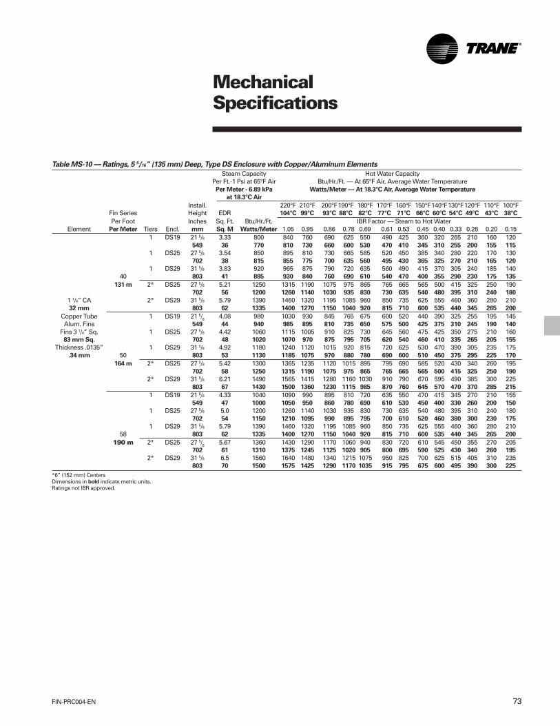
73FIN-PRC004-EN
MechanicalSpecifications
Table MS-10 — Ratings, 5 5/16” (135 mm) Deep, Type DS Enclosure with Copper/Aluminum Elements
Steam Capacity Hot Water CapacityPer Ft.-1 Psi at 65°F Air Btu/Hr./Ft. — At 65°F Air, Average Water TemperaturePer Meter - 6.89 kPa Watts/Meter — At 18.3°C Air, Average Water Temperature
at 18.3°C Air
Install. 220°F 210°F 200°F190°F 180°F 170°F 160°F 150°F140°F130°F120°F 110°F 100°FFin Series Height EDR 104°C 99°C 93°C 88°C 82°C 77°C 71°C 66°C 60°C 54°C 49°C 43°C 38°C
Per Foot Inches Sq. Ft. Btu/Hr./Ft. IBR Factor — Steam to Hot WaterElement Per Meter Tiers Encl. mm Sq. M Watts/Meter 1.05 0.95 0.86 0.78 0.69 0.61 0.53 0.45 0.40 0.33 0.26 0.20 0.15
1 DS19 21 5/8 3.33 800 840 760 690 625 550 490 425 360 320 265 210 160 120549 36 770 810 730 660 600 530 470 410 345 310 255 200 155 115
1 DS25 27 5/8 3.54 850 895 810 730 665 585 520 450 385 340 280 220 170 130702 38 815 855 775 700 635 560 495 430 365 325 270 210 165 120
1 DS29 31 5/8 3.83 920 965 875 790 720 635 560 490 415 370 305 240 185 14040 803 41 885 930 840 760 690 610 540 470 400 355 290 230 175 135
131 m 2* DS25 27 5/8 5.21 1250 1315 1190 1075 975 865 765 665 565 500 415 325 250 190702 56 1200 1260 1140 1030 935 830 730 635 540 480 395 310 240 180
1 1/4” CA 2* DS29 31 5/8 5.79 1390 1460 1320 1195 1085 960 850 735 625 555 460 360 280 21032 mm 803 62 1335 1400 1270 1150 1040 920 815 710 600 535 440 345 265 200
Copper Tube 1 DS19 21 5/8 4.08 980 1030 930 845 765 675 600 520 440 390 325 255 195 145Alum. Fins 549 44 940 985 895 810 735 650 575 500 425 375 310 245 190 140
Fins 3 1/4” Sq. 1 DS25 27 5/8 4.42 1060 1115 1005 910 825 730 645 560 475 425 350 275 210 16083 mm Sq. 702 48 1020 1070 970 875 795 705 620 540 460 410 335 265 205 155
Thickness .0135” 1 DS29 31 5/8 4.92 1180 1240 1120 1015 920 815 720 625 530 470 390 305 235 175.34 mm 50 803 53 1130 1185 1075 970 880 780 690 600 510 450 375 295 225 170
164 m 2* DS25 27 5/8 5.42 1300 1365 1235 1120 1015 895 795 690 585 520 430 340 260 195702 58 1250 1315 1190 1075 975 865 765 665 565 500 415 325 250 190
2* DS29 31 5/8 6.21 1490 1565 1415 1280 1160 1030 910 790 670 595 490 385 300 225803 67 1430 1500 1360 1230 1115 985 870 760 645 570 470 370 285 215
1 DS19 21 5/8 4.33 1040 1090 990 895 810 720 635 550 470 415 345 270 210 155549 47 1000 1050 950 860 780 690 610 530 450 400 330 260 200 150
1 DS25 27 5/8 5.0 1200 1260 1140 1030 935 830 730 635 540 480 395 310 240 180702 54 1150 1210 1095 990 895 795 700 610 520 460 380 300 230 175
1 DS29 31 5/8 5.79 1390 1460 1320 1195 1085 960 850 735 625 555 460 360 280 21058 803 62 1335 1400 1270 1150 1040 920 815 710 600 535 440 345 265 200
190 m 2* DS25 27 5/8 5.67 1360 1430 1290 1170 1060 940 830 720 610 545 450 355 270 205702 61 1310 1375 1245 1125 1020 905 800 695 590 525 430 340 260 195
2* DS29 31 5/8 6.5 1560 1640 1480 1340 1215 1075 950 825 700 625 515 405 310 235803 70 1500 1575 1425 1290 1170 1035 915 795 675 600 495 390 300 225
*6” (152 mm) CentersDimensions in bold indicate metric units.Ratings not IBR approved.

FIN-PRC004-EN74
Features andBenefits
The Trane hydronic security wall finenclosures have been designed fornatural convection in slope top (Type S)and flat top (Type F) configurations in 12”(305 mm) and 18” (457 mm) heights witha depth of 5 5/16” (135 mm), primarily foruse in maximum security applicationssuch as prisons and mental institutions.
Security wall fin is also recommendedfor use in schools, dormitories, nursinghomes, athletic facilities, day carecenters, detention homes, psychiatriccenters, public type buildings and otherheavy abuse areas.
Wrap-Around DesignEach enclosure’s top/front/bottom panelis of one-piece full wrap-around designfor complete engagement with the wallto help prevent access to the inside of theunit. All enclosure panels aremanufactured with 1/8” (3 mm) diameterholes on 3/16” (5 mm) staggered centersfor a partial perforated (inlet and outlet)panel with internal interlocking slip joints.Optional fully-perforated enclosures ofthe entire panel are available with anintermediate overlapping wall sleevewith pre- punched fastener holes forpanel-to- panel alignment and fastening.
Simple installation, made of 14-gauge(1.9 mm thickness) steel, and durabilityare made possible by a continuouspartial back plate/mounting strip. A fullback plate/mounting strip manufacturedfrom 14-gauge (1.9 mm thickness) steelis optional.
Durable ConstructionA variety of heating elements is availablealong with a complete line ofaccessories. Manufactured from 14-gauge (1.9 mm thickness) steel forstrength, these accessories allow forwall-to-wall installation that isarchitecturally compatible with mostinterior designs.
Heating elements or return and supplypiping are secured to the wall with walltype element brackets manufactured of14-gauge (1.9 mm thickness) galvanealSteel with channel-formed edges forrigidity. Each wall bracket is furnishedwith galvanized element cradles andnylon inserts with snap-in rust-resistantnickel-chromium plated ball bearings forsilent glide operation of the heatingelement.
Rigid front panels are constructed of 14-gauge (1.9 mm thickness) or 12- gauge(2.7 mm thickness) steel.
Vandal-ResistantThe security enclosure offers vandal-resistant construction.
Tamper resistant helps prevent vandalsfrom concealing undesirable orhazardous items within the enclosure.
Clean, Even HeatOnly the air within the room isrecirculated, so walls and furnishingsstay cleaner.
A baked-on commercial primer paint isstandard.
AttractiveAvailable with six optional baked-onenamel color finishes chosen fromTrane’s Color Selection Chart UNT-S-10.
Security Wall Fin

75FIN-PRC004-EN
Accessories All 14-Gauge
2” Joiner Piece(Fastener Holes Pre-punched)For use with Fully Perforated 14-gaugeand 12-gauge enclosures only.
End Trim(No Fastener Holes)
End Cap Inside or Outside Corder

FIN-PRC004-EN76
Model NumberDescription Security Wall Fin
Digits 123 45 67 89 S12 - SP - 14 - E
Digits 1 — Enclosure TypeS = Slope TopF = Flat Top
Digit 2 and 3 — Enclosure Size12 = 12” High x 5 5/16” Deep*18 = 18” High x 5 5/16” Deep**
Digit 4 — Type EnclosureS = Security
Digit 5 — Perforation TypeP = Partially PerforatedF = Fully Perforated
Digits 6 and 7 — Gauge14 = 14-gauge12 = 12-gauge
Digits 8 and 9 — Enclosure/Front PanelE = Complete EnclosureFP = Front Panel Only
Note: (E) = 14-Gauge or 12-Gaugefront panel with 14-gauge partial backplate/mounting strip and wallmounting element brackets.
*For single tier of element only.
**Ok for single or two tier elementinstallations.

77FIN-PRC004-EN
PerformanceData Security Wall Fin
Table PD-1 — Copper/Aluminum Elements — Btu/Hour/Foot
SteamRating Hot Water (Ave.)
Copper/Aluminum Elements with Partially Perforated Enclosures 215°F 220°F 210°F 200°F 190°F 180°F 170°F 160°F 150°F 140°F 130°FTube Fin Size Fins/ Encl. Tiers & Mtg. Height Factor FactorSize Inches Foot Type Centers Inches 1.00 1.05 0.95 0.86 0.78 0.69 0.61 0.53 0.45 0.40 0.33
S12-SP 1 16 1310 1380 1250 1130 1020 900 800 690 590 520 430S18-SP 1 22 1550 1630 1480 1330 1210 1070 950 820 700 620 510
3/4” 41/4“x35/8” 40 S18-SP 2-6” 22 2270 2390 2160 1950 1770 1570 1380 1200 1020 910 750F12-SP 1 16 1200 1260 1140 1030 930 830 730 640 540 480 400F18-SP 1 22 1400 1470 1330 1200 1090 970 850 740 630 560 460F18-SP 2-6” 22 2080 2190 1980 1790 1620 1440 1270 1100 940 830 690S12-SP 1 16 1430 1500 1360 1230 1120 990 870 760 640 570 470S18-SP 1 22 *1790 1880 1700 1540 1400 1240 1090 950 810 720 590
3/4” 41/4“x35/8” 50 S18-SP 2-6” 22 2400 2520 2280 2060 1870 1660 1460 1270 1080 960 790F12-SP 1 16 1350 1420 1280 1160 1050 930 820 720 610 540 450F18-SP 1 22 1610 1690 1530 1380 1260 1110 980 850 720 640 530F18-SP 2-6” 22 2290 2400 2180 1970 1790 1580 1400 1210 1030 920 760S12-SP 1 16 1490 1560 1420 1280 1160 1030 910 790 670 600 490S18-SP 1 22 1730 1820 1640 1490 1350 1190 1060 920 780 690 570
1” 41/4“x41/4” 40 S18-SP 2-6” 22 2390 2510 2270 2060 1860 1650 1460 1270 1080 960 790F12-SP 1 16 1360 1430 1290 1170 1060 940 830 720 610 540 450F18-SP 1 22 1550 1630 1470 1330 1210 1070 950 820 700 620 510F18-SP 2-6” 22 2290 2400 2180 1970 1790 1580 1400 1210 1030 920 760S12-SP 1 16 1570 1650 1490 1350 1220 1080 960 830 710 630 520S18-SP 1 22 1980 2080 1880 1700 1540 1370 1210 1050 890 790 650
1” 41/4“x41/4” 50 S18-SP 2-6” 22 2260 2370 2150 1940 1760 1560 1380 1200 1020 900 750F12-SP 1 16 1470 1540 1400 1260 1150 1010 900 780 660 590 480F18-SP 1 22 1770 1860 1680 1520 1380 1220 1080 940 800 710 580F18-SP 2-6” 22 2150 2260 2040 1850 1680 1480 1310 1140 970 860 710S12-SP 1 16 1470 1540 1400 1260 1150 1010 900 780 660 590 480S18-SP 1 22 1700 1790 1620 1460 1330 1170 1040 900 770 680 560
11/4” 4 1/4“x41/4” 40 S18-SP 2-6” 22 *2350 2470 2230 2020 1830 1620 1430 1250 1060 940 780F12-SP 1 16 1340 1410 1270 1150 1050 920 820 710 600 540 440F18-SP 1 22 1530 1610 1450 1320 1190 1060 930 810 690 610 500F18-SP 2-6” 22 2250 2360 2140 1940 1760 1550 1370 1190 1010 900 740S12-SP 1 16 *1540 1620 1460 1320 1200 1060 940 820 690 620 510S18-SP 1 22 *1940 2040 1840 1670 1510 1340 1180 1030 870 780 640
11/4” 41/4“x41/4” 50 S18-SP 2-6” 22 2220 2330 2110 1910 1730 1530 1350 1180 1000 890 730F12-SP 1 16 1450 1520 1380 1250 1130 1000 880 770 650 580 480F18-SP 1 22 1740 1830 1650 1500 1360 1200 1060 920 780 700 570F18-SP 2-6” 22 2110 2220 2000 1810 1650 1460 1290 1120 950 840 700
1. *I = B = R Rating on Assemblies as marked.2. Mounting Height is the dimension from the floor to the top of the enclosure to obtain listed capacities.3. Two-tier applications can only be used with 18” high enclosures installed on 6” center lines.
Finned Tube RadiationModel S and F — Security Enclosures Partially PerforatedCapacity Data

FIN-PRC004-EN78
PerformanceData Security Wall Fin
Table PD-2 — Copper/Aluminum Elements — Watts/Meter
SteamRating Hot Water (Ave.)
Copper/Aluminum Elements with Partially Perforated Enclosures 102°C 104°C 99°C 93°C 88°C 82°C 77°C 71°C 66°C 60°C 54°CTube Fin Size Fins/ Encl. Tiers & Mtg. Height Factor FactorSize Inches Foot Type Centers Inches 1.00 1.05 0.95 0.86 0.78 0.69 0.61 0.53 0.45 0.40 0.33
S12-SP 1 406 1260 1330 1200 1090 980 870 770 660 570 500 410S18-SP 1 559 1490 1570 1420 1280 1160 1030 910 790 670 600 490
19 mm 108 x 92 131 S18-SP 2-152 mm 559 2180 2300 2080 1870 1700 1510 1330 1150 980 870 720F12-SP 1 406 1150 1210 1100 990 890 800 700 620 520 460 380F18-SP 1 559 1350 1410 1280 1150 1050 930 820 710 610 540 440F18-SP 2-152 mm 559 2000 2110 1900 1720 1560 1380 1220 1060 900 800 660S12-SP 1 406 1370 1440 1310 1180 1080 950 840 730 620 550 450S18-SP 1 559 *1720 1810 1630 1480 1350 1190 1050 910 780 690 590
19 mm 108 x 92 164 S18-SP 2-152 mm 559 2310 2420 2190 1980 1800 1600 1400 1220 1040 920 760F12-SP 1 406 1300 1360 1230 1120 1010 890 790 690 590 520 430F18-SP 1 559 1550 1620 1470 1330 1210 1070 940 820 690 620 510F18-SP 2-152 mm 559 2200 2310 2100 1890 1720 1520 1350 1160 990 880 730S12-SP 1 406 1430 1500 1370 1230 1120 990 870 760 640 580 470S18-SP 1 559 1660 1750 1580 1430 1300 1140 1020 880 750 660 550
25 mm 108 x 108 131 S18-SP 2-152 mm 559 2300 2410 2180 1980 1790 1590 1400 1220 1040 920 760F12-SP 1 406 1310 1370 1240 1120 1020 900 800 690 590 520 430F18-SP 1 559 1490 1570 1410 1280 1160 1030 910 790 670 600 490F18-SP 2-152 mm 559 2200 2310 2100 1890 1720 1520 1350 1160 990 880 730S12-SP 1 406 1510 1590 1430 1300 1170 1040 920 800 680 610 500S18-SP 1 559 1900 2000 1810 1630 1480 1320 1160 1010 860 760 620
25 mm 108 x 108 164 S18-SP 2-152 mm 559 2170 2280 2070 1860 1690 1500 1330 1150 980 870 720F12-SP 1 406 1410 1480 1350 1210 1110 970 870 750 630 570 460F18-SP 1 559 1700 1790 1610 1460 1330 1170 1040 900 770 680 560F18-SP 2-152 mm 559 2070 2170 1960 1780 1610 1420 1260 1100 930 830 680S12-SP 1 406 1410 1480 1350 1210 1110 970 870 750 630 570 460S18-SP 1 559 1630 1720 1560 1400 1280 1120 1000 870 740 650 540
32 mm 108 x 108 131 S18-SP 2-152 mm 559 *2260 2370 2140 1940 1760 1560 1370 1200 1020 900 750F12-SP 1 406 1290 1360 1220 1110 1010 880 790 680 580 520 420F18-SP 1 559 1470 1550 1390 1270 1140 1020 890 780 660 590 480F18-SP 2-152 mm 559 2160 2270 2060 1860 1690 1490 1320 1140 970 870 710S12-SP 1 406 *1480 1560 1400 1270 1150 1020 900 790 660 600 490S18-SP 1 559 *1860 1960 1760 1610 1450 1290 1130 990 840 750 620
32 mm 108 x 108 164 S18-SP 2-152 mm 559 2130 2240 2030 1840 1660 1470 1300 1130 960 860 700F12-SP 1 406 1390 1460 1330 1200 1090 960 850 740 620 560 460F18-SP 1 559 1670 1760 1590 1440 1310 1150 1020 880 750 670 550F18-SP 2-152 mm 559 2030 2130 1920 1740 1590 1400 1240 1080 910 810 670
1. *I = B = R Rating on Assemblies as marked.2. Mounting Height is the dimension from the floor to the top of the enclosure to obtain listed capacities.3. Two-tier applications can only be used with 457 mm high enclosures installed on 152 mm center lines.

79FIN-PRC004-EN
PerformanceData Security Wall Fin
Table PD-3 — Steel Tube/Fin Elements — Btu/Hour/Foot
Hot Water (Ave.)Steel Tube/Fin Elements with Partially Perforated Enclosures 220°F 210°F 200°F 190°F 180°F 170°F 160°F 150°F 140°F 130°F
Mtg. SteamTube Fin Size Fins/ Encl. Tiers & Height Rating FactorSize Inches Foot Type Centers Inches 1.00 1.05 0.95 0.86 0.78 0.69 0.61 0.53 0.45 0.40 0.33
S12-SP 1 16 1280 1340 1220 1100 1000 880 780 680 580 510 420S18-SP 1 22 1380 1450 1310 1190 1080 950 840 730 620 550 460
11/4” 41/4“x4 1/4” 40 S18-SP 2-6” 22 2140 2250 2030 1840 1670 1480 1310 1130 960 860 710F12-SP 1 16 1150 1210 1090 990 900 790 700 610 520 460 380F18-SP 1 22 1230 1290 1170 1060 960 850 750 650 550 490 410F18-SP 2-6” 22 1980 2080 1880 1700 1540 1370 1210 1050 890 790 650S12-SP 1 16 1100 1160 1050 950 860 760 670 580 500 440 360S18-SP 1 22 1180 1240 1120 1010 920 810 720 630 530 470 390
11/4” 4 /4“x41/4” 32 S18-SP 2-6” 22 1840 1930 1750 1580 1440 1270 1120 980 830 740 610F12-SP 1 16 990 1040 940 850 770 680 600 520 450 400 330F18-SP 1 22 1060 1110 1010 910 830 730 650 560 480 420 350F18-SP 2-6” 22 1700 1790 1620 1460 1330 1170 1040 900 770 680 560
1. *I = B = R Rating on Assemblies as marked.2. Mounting Height is the dimension from the floor to the top of the enclosure to obtain listed capacities.3. Two-tier applications can only be used with 18” high enclosures installed on 6” center lines.
Table PD-4— Steel Tube/Fin Elements — Watts/Meter
Hot Water (Ave.)Steel Tube/Fin Elements with Partially Perforated Enclosures 104°C 99°C 93°C 88°C 82°C 77°C 71°C 66°C 60°C 54°C
Mtg. SteamTube Fin Size Fins/ Encl. Tiers & Height Rating Factor
Size Inches Foot Type Centers Inches 1.00 1.05 0.95 0.86 0.78 0.69 0.61 0.53 0.45 0.40 0.33S12-SP 1 406 1230 1290 1170 1060 960 850 750 650 560 490 400S18-SP 1 559 1330 1390 1260 1140 1040 910 810 700 600 530 440
32 mm 108 x 131 S18-SP 2-152 mm 559 2060 2160 1950 1770 1600 1420 1260 1090 920 830 680108 F12-SP 1 406 1110 1160 1050 950 870 760 670 590 500 440 370
F18-SP 1 559 1180 1240 1120 1020 920 820 720 620 530 470 390F18-SP 2-152 mm 559 1900 2000 1810 1630 1480 1320 1160 1010 860 760 620S12-SP 1 406 1060 1120 1010 910 830 730 640 560 480 420 350S18-SP 1 559 1130 1190 1080 970 880 780 690 610 510 450 370
32 mm 108 x 105 S18-SP 2-152 mm 559 1770 1860 1680 1520 1380 1220 1080 940 800 710 590108 F12-SP 1 406 950 1000 900 820 740 650 580 500 430 380 320
F18-SP 1 559 1020 1070 970 870 800 700 620 540 460 400 340F18-SP 2-152 mm 559 1630 1720 1560 1400 1280 1120 1000 870 740 650 540
1. *I = B = R Rating on Assemblies as marked.2. Mounting Height is the dimension from the floor to the top of the enclosure to obtain listed capacities.3. Two-tier applications can only be used with 457 mm high enclosures installed on 152 mm center lines.

FIN-PRC004-EN80
PerformanceData Security Wall Fin
Finned Tube RadiationModel S and F — Security Enclosures Fully PerforatedCapacity Data
Table PD-5— Copper/Aluminum Elements — Btu/Hour/Foot
SteamRating Hot Water
Copper/Aluminum Elements with Fully Perforated Enclosures 215°F 220°F 210°F 200°F 190°F 180°F 170°F 160°F 150°F 140°F 130°FTube Fin Size Fins/ Encl. Tiers & Mtg. Height Factor FactorSize Inches Foot Type Centers Inches 1.00 1.05 0.95 0.86 0.78 0.69 0.61 0.53 0.45 0.40 0.33
S12-SF 1 16 1240 1300 1180 1070 970 860 760 660 560 500 410S18-SF 1 22 1290 1350 1230 1110 1010 890 790 680 580 5204 30
3/4” 41/4” x 35/8” 40 S18-SF 2-6” 22 2230 2340 2120 1920 1740 1540 1360 1180 1000 890 740F12-SF 1 16 1140 1200 1080 980 890 790 700 600 510 460 380F18-SF 1 22 1170 1230 1110 1010 910 810 710 620 530 470 390F18-SF 2-6” 22 2040 2140 1940 1750 1590 1410 1240 1080 920 820 670S12-SF 1 16 1350 1420 1280 1160 1050 930 820 720 610 540 450S18-SF 1 22 1400 1470 1330 1200 1090 970 850 740 630 560 460
3/4” 41/4” x 35/8” 50 S18-SF 2-6” 22 2390 2510 2270 2060 1860 1650 1460 1270 1080 960 790F12-SF 1 16 1270 1330 1210 1090 990 880 770 670 570 510 420F18-SF 1 22 1290 1350 1230 1110 1010 890 790 680 580 520 430F18-SF 2-6” 22 2280 2390 2170 1960 1780 1570 1390 1210 1030 910 750S12-SF 1 16 1430 1500 1360 1230 1120 990 870 760 640 570 470S18-SF 1 22 1480 1550 1410 1270 1150 1020 900 780 670 590 490
1” 41/4” x 41/4” 40 S18-SF 2-6” 22 2560 2690 2430 2200 2000 1770 1560 1360 1150 1020 840F12-SF 1 16 1310 1380 1240 1130 1020 900 800 690 590 520 430F18-SF 1 22 1330 1400 1260 1140 1040 920 810 700 600 530 440F18-SF 2-6” 22 2450 2570 2330 2110 1910 1690 1490 1300 1100 980 810S12-SF 1 16 1470 1540 1400 1260 1150 1010 900 780 660 590 490S18-SF 1 22 1530 1610 1450 1320 1190 1060 930 810 690 610 500
1” 41/4” x 41/4” 50 S18-SF 2-6” 22 2590 2720 2460 2230 2020 1790 1580 1370 1170 1040 850F12-SF 1 16 1380 1450 1310 1190 1080 950 840 730 620 550 460F18-SF 1 22 1420 1490 1350 1220 1110 980 870 750 640 570 470F18-SF 2-6” 22 2460 2580 2340 2120 1920 1700 1500 1300 1110 980 810S12-SF 1 16 1400 1470 1330 1200 1090 970 850 740 630 560 460S18-SF 1 22 1460 1530 1390 1260 1140 1010 890 770 660 580 480
11/4” 41/4” x 4 /4” 40 S18-SF 2-6” 22 *2520 2650 2390 2170 1970 1740 1540 1340 1130 1010 830F12-SF 1 16 1280 1340 1220 1100 1000 880 780 680 580 510 420F18-SF 1 22 1310 1380 1240 1130 1020 900 800 690 590 520 430F18-SF 2-6” 22 2410 2530 2290 2070 1880 1660 1470 1280 1080 960 800S12-SF 1 16 1440 1510 1370 1240 1120 990 880 760 650 580 480S18-SF 1 22 1500 1580 1430 1290 1170 1040 920 800 680 600 500
11/4” 41/4” x 4 /4” 50 S18-SF 2-6” 22 2550 2680 2420 2190 1990 1760 1560 1350 1150 1020 840F12-SF 1 16 1360 1430 1290 1170 1060 940 830 720 610 540 450F18-SF 1 22 1400 1470 1330 1200 1090 970 850 740 630 560 460F18-SF 2-6” 22 2420 2540 2300 2080 1890 1670 1480 1280 1090 970 800
1. *I = B = R Rating on Assemblies as marked.2. Mounting Height is the dimension from the floor to the top of the enclosure to obtain listed capacities.3. Two-tier applications can only be used with 18” high enclosures installed on 6” center lines.
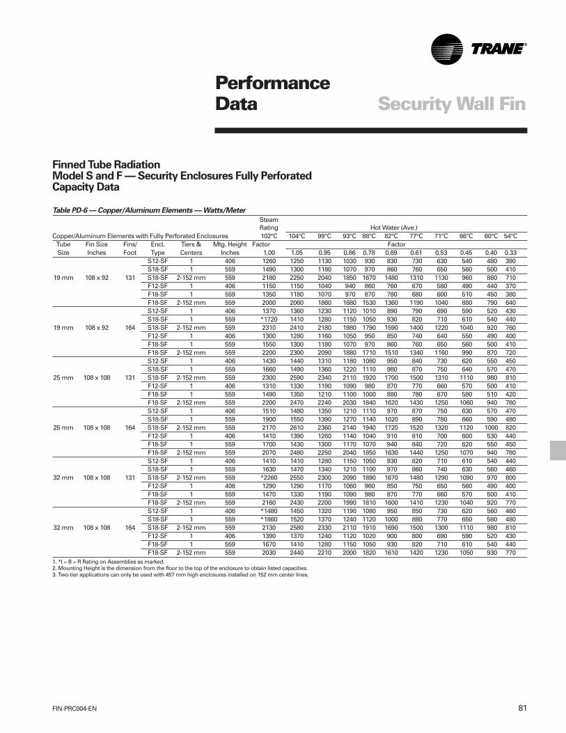
81FIN-PRC004-EN
PerformanceData Security Wall Fin
Table PD-6 — Copper/Aluminum Elements — Watts/Meter
SteamRating Hot Water (Ave.)
Copper/Aluminum Elements with Fully Perforated Enclosures 102°C 104°C 99°C 93°C 88°C 82°C 77°C 71°C 66°C 60°C 54°CTube Fin Size Fins/ Encl. Tiers & Mtg. Height Factor FactorSize Inches Foot Type Centers Inches 1.00 1.05 0.95 0.86 0.78 0.69 0.61 0.53 0.45 0.40 0.33
S12-SF 1 406 1260 1250 1130 1030 930 830 730 630 540 480 390S18-SF 1 559 1490 1300 1180 1070 970 860 760 650 560 500 410
19 mm 108 x 92 131 S18-SF 2-152 mm 559 2180 2250 2040 1850 1670 1480 1310 1130 960 860 710F12-SF 1 406 1150 1150 1040 940 860 760 670 580 490 440 370F18-SF 1 559 1350 1180 1070 970 870 780 680 600 510 450 380F18-SF 2-152 mm 559 2000 2060 1860 1680 1530 1360 1190 1040 880 790 640S12-SF 1 406 1370 1360 1230 1120 1010 890 790 690 590 520 430S18-SF 1 559 *1720 1410 1280 1150 1050 930 820 710 610 540 440
19 mm 108 x 92 164 S18-SF 2-152 mm 559 2310 2410 2180 1980 1790 1590 1400 1220 1040 920 760F12-SF 1 406 1300 1280 1160 1050 950 850 740 640 550 490 400F18-SF 1 559 1550 1300 1180 1070 970 860 760 650 560 500 410F18-SF 2-152 mm 559 2200 2300 2090 1880 1710 1510 1340 1160 990 870 720S12-SF 1 406 1430 1440 1310 1180 1080 950 840 730 620 550 450S18-SF 1 559 1660 1490 1360 1220 1110 980 870 750 640 570 470
25 mm 108 x 108 131 S18-SF 2-152 mm 559 2300 2590 2340 2110 1920 1700 1500 1310 1110 980 810F12-SF 1 406 1310 1330 1190 1090 980 870 770 660 570 500 410F18-SF 1 559 1490 1350 1210 1100 1000 880 780 670 580 510 420F18-SF 2-152 mm 559 2200 2470 2240 2030 1840 1620 1430 1250 1060 940 780S12-SF 1 406 1510 1480 1350 1210 1110 970 870 750 630 570 470S18-SF 1 559 1900 1550 1390 1270 1140 1020 890 780 660 590 480
25 mm 108 x 108 164 S18-SF 2-152 mm 559 2170 2610 2360 2140 1940 1720 1520 1320 1120 1000 820F12-SF 1 406 1410 1390 1260 1140 1040 910 810 700 600 530 440F18-SF 1 559 1700 1430 1300 1170 1070 940 840 720 620 550 450F18-SF 2-152 mm 559 2070 2480 2250 2040 1850 1630 1440 1250 1070 940 780S12-SF 1 406 1410 1410 1280 1150 1050 930 820 710 610 540 440S18-SF 1 559 1630 1470 1340 1210 1100 970 860 740 630 560 460
32 mm 108 x 108 131 S18-SF 2-152 mm 559 *2260 2550 2300 2090 1890 1670 1480 1290 1090 970 800F12-SF 1 406 1290 1290 1170 1060 960 850 750 650 560 490 400F18-SF 1 559 1470 1330 1190 1090 980 870 770 660 570 500 410F18-SF 2-152 mm 559 2160 2430 2200 1990 1810 1600 1410 1230 1040 920 770S12-SF 1 406 *1480 1450 1320 1190 1080 950 850 730 620 560 460S18-SF 1 559 *1860 1520 1370 1240 1120 1000 880 770 650 580 480
32 mm 108 x 108 164 S18-SF 2-152 mm 559 2130 2580 2330 2110 1910 1690 1500 1300 1110 980 810F12-SF 1 406 1390 1370 1240 1120 1020 900 800 690 590 520 430F18-SF 1 559 1670 1410 1280 1150 1050 930 820 710 610 540 440F18-SF 2-152 mm 559 2030 2440 2210 2000 1820 1610 1420 1230 1050 930 770
1. *I = B = R Rating on Assemblies as marked.2. Mounting Height is the dimension from the floor to the top of the enclosure to obtain listed capacities.3. Two-tier applications can only be used with 457 mm high enclosures installed on 152 mm center lines.
Finned Tube RadiationModel S and F — Security Enclosures Fully PerforatedCapacity Data

FIN-PRC004-EN82
PerformanceData Security Wall Fin
Table PD-7 — Steel Tube/Fin Elements — Btu/Hour/Foot
SteamRating Hot Water (Ave.)
Steel Tube/Fin Elements with Fully Perforated Enclosures 215°F 220°F 210°F 200°F 190°F 180°F 170°F 160°F 150°F 140°F 130°FMtg.
Tube Fin Size Fins/ Encl. Tiers & Height Factor FactorSize Inches Foot Type Centers Inches 1.00 1.05 0.95 0.86 0.78 0.69 0.61 0.53 0.45 0.40 0.33
S12-SF 1 16 1250 1310 1190 1080 980 860 760 660 560 500 410S18-SF 1 22 1300 1370 1240 1120 1010 900 790 690 590 520 430
11/4” 41/4” x 41/4” 40 S18-SF 2-6” 22 2250 2360 2140 1940 1760 1550 1370 1190 1010 900 740F12-SF 1 16 1120 1180 1060 960 870 770 680 590 500 450 370F18-SF 1 22 1160 1220 1100 1000 900 800 710 610 520 460 380F18-SF 2-6” 22 2080 2180 1980 1790 1620 1440 1270 1100 940 830 690S12-SF 1 16 1070 1170 1060 960 870 770 680 590 500 450 370S18-SF 1 22 1110 1190 1080 970 880 780 690 600 510 450 370
11/4” 41/4” x 41/4” 32 S18-SF 2-6” 22 1930 2170 1970 1780 1620 1430 1260 1090 930 830 680F12-SF 1 16 960 1050 950 860 780 690 610 530 450 400 330F18-SF 1 22 1000 1060 960 870 780 690 620 530 450 400 340F18-SF 2-6” 22 1790 2010 1820 1650 1490 1320 1170 1010 860 760 630
1. Mounting Height is the dimension from the floor to the top of the enclosure to obtain listed capacities.2. Two-tier applications can only be used with 18” high enclosures installed on 6” center lines.
Table PD-8 — Steel Tube/Fin Elements — Watts/Meter
Hot Water (Ave.)Steel Tube/Fin Elements with Fully Perforated Enclosures 104°C 99°C 93°C 88°C 82°C 77°C 71°C 66°C 60°C 54°C
Mtg. SteamTube Fin Size Fins/ Encl. Tiers & Height Rating FactorSize mm Meter Type Centers mm 102°C 1.05 0.95 0.86 0.78 0.69 0.61 0.53 0.45 0.40 0.33
S12-SF 1 406 1230 1260 1140 1040 940 830 730 630 540 480 390S18-SF 1 559 1330 1320 1190 1080 970 870 760 660 570 500 410
32 mm 108 x 108 131 S18-SF 2-152 mm 559 2060 2270 2060 1860 1690 1490 1320 1140 970 870 710F12-SF 1 406 1110 1130 1020 920 840 740 650 570 480 430 360F18-SF 1 559 1180 1170 1060 960 870 770 680 590 500 440 370F18-SF 2-152 mm 559 1900 2100 1900 1720 1560 1380 1220 1060 900 800 660S12-SF 1 406 1060 1080 980 890 810 710 630 540 460 410 340S18-SF 1 559 1130 1140 1020 930 830 750 650 570 490 430 350
32 mm 108 x 108 105 S18-SF 2-152 mm 559 1770 1950 1770 1600 1450 1280 1140 980 830 750 610F12-SF 1 406 950 970 880 790 720 640 560 490 410 370 310F18-SF 1 559 1020 1010 910 830 750 660 580 510 430 380 320F18-SF 2-152 mm 559 1630 1810 1630 1480 1340 1190 1050 910 770 690 570
1. *I = B = R Rating on Assemblies as marked.2. Mounting Height is the dimension from the floor to the top of the enclosure to obtain listed capacities.3. Two-tier applications can only be used with 457 mm high enclosures installed on 152 mm center lines.

83FIN-PRC004-EN
PerformanceData
Table PD-9 — Ratings of Security Wall Fin Copper/Aluminum Elements Without Enclosures
Steam Capacity Hot Water CapacityPer Ft. — 1 Psi at 65°F Air Btu/Hr/Ft — At 65°F Air, Average Water TemperaturePer Meter — 6.895 kPa Watts/Meters — At 18.3°C Air, Average Water Temperature
at 18.3°C Air 200°F 190°F 180°F 170°F 160°F 150°F
Fin Size Fin Series Fin Install. 93°C 88°C 82°C 77°C 71°C 66°C
Element Inches Per Foot Thickness Height Btu/Hr./Ft IBR Factor — Steam to Hot WaterSize Model (mm) Per Meter Inches (mm) Tiers Inches (mm) (Watts/Meter) 0.86 0.78 0.69 0.61 0.53 0.453/4” 3CA4340 4 1/4” x 3 5/8” 40 .020” 1 9 3/8 1470 1260 1150 1010 900 780 660(19) (108 x 92) (131 m) (.51) (238.00) (1410) (1210) (1110) (971) (865) (750) (635)
2-6 CL 15 3/8 2580 2200 2010 1780 1570 1370 1160(152) (391.00) (2480) (2120) (1930) (1710) (1510) (1320) (1120)
3-6 CLS 21 3/8 3500 3010 2730 2420 2140 1860 1580(152) (543.00) (3370) (2890) (2620) (2330) (2060) (1790) (1520)
3/4” 3CA4350 4 1/4” x 3 5/8” 50 .020” 1 9 3/8 1600 1380 1250 1100 980 850 720(19) (108 x 92) (164 m) (.51) (238.00) (1540) (1330) (1200) (1060) (942) (817) (692)
2-6 CL 15 3/8 2680 2300 2090 1850 1630 1420 1210(152) (391.00) (2580) (2210) (2010) (1780) (1570) (1360) (1160)
3-6 CL 21 3/8 3600 3100 2810 2480 2200 1910 1620(152) (543.00) (3460) (2980) (2700) (2380) (2120) (1840) (1560)
1” 1CA4440 4 1/4” x 4 1/4” 40 .020” 1 9 3/8 1690 1450 1320 1170 1030 900 760(25) (108 x 108) (131 m) (.51 m) (238.00) (1620) (1390) (1270) (1120) (990) (865) (731)
2-6 CL 15 3/8 2730 2350 2130 1880 1670 1450 1230(152) (391.00) (2620) (2260) (2050) (1810) (1610) (1390) (1180)
3-6 CL 21 3/8 3560 3060 2780 2460 2170 1890 1600(152) (543.00) (3420) (2940) (2670) (2370) (2090) (1820) (1540)
1” 1CA4450 4 1/4” x 4 1/4” 50 .020” 1 9 3/8 1740 1500 1360 1200 1060 920 780(25) (108 x 108) (164 m) (.51 (238.00) (1670) (1440) (1310) (1150) (1020) (885) (750)
2-6 CL 15 3/8 2510 2160 1960 1730 1530 1330 1310(152) (391.00) (2410) (2080) (1880) (1660) (1470) (1280) (1260)
3-6 CL 21 3/8 3260 2800 2540 2250 1990 1730 1470(152) (543.00) (3140) (2690) (2440) (2160) (1910) (1660) (1410)
1 1/4” 4CA4440 4 1/4” x 4 1/4” 40 .020” *1 9 3/8 1660 1430 1290 1150 1010 880 750(32) (108 x 108) (131 m) (.51) (238.00) (1600) (1380) (1240) (1110) (971) (846) (721)
*2-6 CL 15 3/8 2680 2300 2090 1850 1630 1420 1200(152) (391.00) (2580) (2210) (2010) (1780) (1570) (1360) (1150)
*3-6 CL 21 3/8 3490 300 2720 2410 2130 1850 1570(152) (543.00) (3360) (288) (2620) (2320) (2050) (1780) (1510)
1 1/4” 4CA4450 4 1/4” x 4 1/4” 50 .020” *1 9 3/8 1710 1470 1330 1180 1040 910 770(32) (108 x 108) (164 m) (.51) (238.00) (1640) (1410) (1280) (1140) (1000) (875) (740)
*2-6 CL 15 3/8 2460 2120 1920 1700 1500 1300 1110(152) (391.00) (2370) (2040) (1850) (1640) (1440) (1250) (1070)
*3-6 CL 21 3/8 3200 2750 2500 2210 1950 1700 1440(152) (543.00) (3080) (2640) (2400) (2120) (1880) (1640) (1380)

FIN-PRC004-EN84
PerformanceData
Table PD-10 — Ratings of Security Wall Fin Steel Elements Without Enclosures
Steam Capacity ]Hot Water CapacityPer Ft. — 1 Psi at 65°F Air Btu/Hr/Ft — At 65°F Air, Average Water Temperature
P6.895 kPa Watts/Meters — At 18.3°C Air, Average Water Temperature
at 18.3°C Air 200°F 190°F 180°F 170°F 160°F 150°F
Fin Size Fin Series Fin Install. 93°C 88°C 82°C 77°C 71°C 66°C
Element Inches Per Foot Thickness Height Btu/Hr./Ft IBR Factor — Steam to Hot WaterSize Model (mm) Per Meter Inches (mm) Tiers Inches (mm) (Watts/Meter) 0.86 0.78 0.69 0.61 0.53 0.451 1/4” 4ST4440 4 1/4” x 4 1/4” 32 .032” 1 9 3/8 1310 1130 1020 900 800 690 590(32) (108 x 108) (105 m) (.81) (238.00) (1260) (1060) (981) (865) (769) (664) (567)
2-6 CL 15 3/8 2300 1980 1790 1590 1400 1220 1040(152) (391.00) (2210) (1900) (1720) (1530) (1350) (1170) (1000)
3-6 CLS 21 3/8 3030 2610 2360 2090 1850 1610 1360(152) (543.00) (2910) (2510) (2270) (2010) (1780) (1550) (1310)
1 1/4” 4ST4432 4 1/4” x 4 1/4” 40 .032” 1 9 3/8 1480 1270 1150 1020 900 750 670(32) (108 x 108) (131 m) (.81) (238.00) (1420) (1220) (1110) (981) (865) (721) (644)
2-6 CL 15 3/8 2440 2100 1900 1680 1490 1290 1100(152) (391.00) (2350) (2020) (1830) (1620) (1430) (1240) (1060)
3-6 CL 21 3/8 3170 2730 2470 2190 1930 1680 1430(152) (543.00) (3050) (2620) (2380) (2110) (1860) (1620) (1380)
2” 2ST4425 4 1/4” x 4 1/4” 25 .032” 1 9 3/8 1140 980 890 790 700 600 510(51) (108 x 108) (82 m) (.81) (238.00) (1100) (942) (856) (760) (673) (577) (490)
2-6 CL 15 3/8 2030 1750 1580 1400 1240 1080 910(152) (391.00) (1950) (1680) (1520) (1350) (1190) (1040) (875)
3-6 CL 21 3/8 2700 2320 2110 1860 1650 1430 1220(152) (543.00) (2600) (2230) (2030) (1790) (1590) (1380) (1170)
2” 2ST4432 4 1/4” x 4 1/4” 32 .032” 1 9 3/8 1320 1140 1030 910 810 700 590(51) (108 x 108) (105 m) (.81) (238.00) (1270) (1100) (990) (875) (779) (673) (567)
2-6 CL 15 3/8 2230 1920 1740 1540 1360 1180 1000(152) (391.00) (2140) (1850) (1670) (1480) (1310) (1140) (962)
3-6 CL 21 3/8 2910 2500 2270 2010 1790 1540 1310(152) (543.00) (2800) (2400) (2180) (1930) (1720) (1480) (1260)
Notes:1. Dimensions in ( ) are shown in millimeters.2. Dimensions in bold indicate metric units.

85FIN-PRC004-EN
DimensionalData Security Wall Fin
Finned Tube Radiation Model S & F — Security Enclosures Partially Perforated
5 5/16”(135 mm)
3/4” (19 mm)
1 3/8” (35 mm)
18” (457 mm)12” (305 mm)
6” (152 mm)2 TIER
18” (457 mm) ONLY
PERFORATEDAREA
6” (152 mm)
2 3/4” (70 mm)
3/4” (19 mm)
2 21/32” (67 mm)
FINISHED FLOOR
2 1/32” (52 mm)
FIN
ISH
ED W
ALL
PERFORATEDAREA4” (MIN)
(102 mm)
(52 mm)
2 1/32”A
5 5/16”(135 mm)
(51 mm) 2”3/4” (19 mm)
1 3/8” (35 mm)PERFORATEDAREA
(30 mm)1 1/4”
18” (457 mm)12” (305 mm)
6” (152 mm)2 TIER
18” (457 mm) ONLY
A (52 mm)
2 1/32”
4” (MIN)(102 mm)
FINISHED FLOOR
PERFORATEDAREA
3/4” (19 mm)
2 21/32” (67 mm)
2 3/4” (70 mm)
6” (152 mm)
FIN
ISH
ED W
ALL
Partially Perforated
Notes:1. For two tiers, 18" high enclosure must be used.

FIN-PRC004-EN86
Finned Tube Radiation Model S & F — Security Enclosures Fully Perforated
5 5/16”(135 mm)
1 3/8” (35 mm)
18” (457 mm)12” (305 mm)
6” (152 mm)2 TIER
18” (457 mm) ONLY
FINISHED FLOOR
4” (MIN)(102 mm
2 21/32” (67 mm)
3/4” (19 mm) 3/4” (16 mm)
6” (152 mm)
FIN
ISH
ED W
ALL
FINISHED FLOOR
4” (MIN)(102 mm
2 21/32” (67 mm)
2 3/4” (70 mm)
6” (152 mm)
FIN
ISH
ED W
ALL
1 3/8” (35 mm)
5 5/16”(135 mm)
(51 mm)2”
6” (152 mm)2 TIER
18” (457 mm) ONLY
18” (457 mm)12” (305 mm)
2 3/4” (70 mm)A
DimensionalData Security Wall Fin
Fully Perforated
Notes:1. For two tiers, 18" high enclosure must be used.

87FIN-PRC004-EN
Slope Top — 12” (305) and 18” (457)
3” (76) End Cap
4” (102), 6” (152), 8 3/8” (213) End Trim
2” Joiner Piece
Dimensions shown in ( ) are in millimeters.
90º Outside Corner
90º Inside Corner
DimensionalData

FIN-PRC004-EN88
DimensionalData
Dimensions shown in ( ) are in millimeters.
Flat Top — 12” (305) and 18” (457)
3” (76) End Cap
4” (102), 6” (152), 8 3/8” (213) End Trim
90º Outside Corner
90º Inside Corner

89FIN-PRC004-EN
DimensionalData
3/4” CA (19) Copper- Aluminum — 40 Fins/Foot (131 Fins/Meter)3/4” CA (19) Copper- Aluminum — 50 Fins/Foot (164 Fins/Meter)
NOTES:1. Fins mechanically bonded to tube2. Fin thickness is .020” (0.51)3. Element lengths from 1’0” (0.30 m) through 8’0” (2.4 m)
1 1/4” CA (32) Copper- Aluminum — 40 Fins/Foot (131 Fins/Meter)1 1/4” CA (32) Copper- Aluminum — 50 Fins/Foot (164 Fins/Meter)
NOTES:1. Fins mechanically bonded to tube2. Fin thickness is .020” (0.51)3. Element lengths from 1’0” (0.30 m) through 12’ (3.66 m)
1” CA (25) Copper-Aluminum — 40 Fins/Foot (131 Fins/Meter)1” CA (25) Copper-Aluminum — 50 Fins/Foot (164 Fins/Meter)
Dimensions shown in ( ) are in millimeters.

FIN-PRC004-EN90
DimensionalData
1 1/4” ST (32) Steel Tube — Steel Fin — 40 Fins/Foot (131 Fins/Meter)1 1/4” ST (32) Steel Tube — Steel Fin — 32 Fins/Foot (105 Fins/Meter)
NOTES:1. Fins mechanically bonded to tube2. Fin thickness is .032” (0.81)3. Element lengths from 1’0” (0.30 m) through 12’ (3.66 m)
2” ST (51) Steel Tube — Steel Fin — 32 Fins/Foot (105 Fins/Meter)2” ST (51) Steel Tube — Steel Fin — 25 Fins/Foot (82 Fins/Meter)
NOTES:1. Fins mechanically bonded to tube2. Fin thickness is .032” (0.81)3. Element lengths from 1’0” (0.30 m) through 12’ (3.66 m)

91FIN-PRC004-EN
MechanicalSpecifications
SecurityEnclosures
Models S and F
SpecificationsNatural convection security wall fin shallbe furnished to meet the specifiedcapacity. Enclosure, heating elementsand accessories shall be installed inaccordance with the manufacturer’srecommendations. All enclosures shallbe tamper-resistant.
MountingHydronic security slope top and flat topwall fin enclosures shall be wall-mounted 3 1/2” (89 mm) to 4” (102 mm)above the floor level to obtain catalogcapacities.
EnclosuresType S — Slope top outlet and Type F —flat top outlet: Each enclosure top/front/bottom panel shall be of one piece (fullwrap-around design) for completeengagement with the wall to preventaccess to the inside of the unit.
Enclosures shall be fabricated from 14-gauge (1.9 mm thickness) steel forstrength and durability. Optional 12-gauge (2.6 mm thickness) steel shall beavailable. All enclosure panels shall bemanufactured with 1/8” (3 mm) diameterholes on 3/16” (5 mm) staggered centersfor a partial perforated (inlet and outlet)panel with internal interlocking slip joints.Optional fully perforated enclosures ofthe entire panel shall be available withintermediate overlapping wall sleevewith pre-punched fastener holes forpanel-to-panel alignment and fastening.
Cabinet depth shall be 5 5/16” (135 mm)for 12” (305 mm) high enclosures forsingle tier element and 18” (457 mm)enclosures for single or double tierelement applications. Enclosures shallbe available in 2-feet (.61 m) through8- feet (2.4 m) in 6” (.15 m) increments.• Partially Perforated — 14-Gauge
(Standard)• Partially Perforated — 12-Gauge
(Optional)• Fully Perforated — 14-Gauge
(Optional)• Fully Perforated — 12-Gauge
(Optional)
Enclosure Suspension SystemEnclosures with (visible tamper- resistantfasteners by others) for heating elementsshall be installed to a continuous partialback plate/mounting strip manufacturedfrom 14-gauge (1.9 mm thickness) steelat the top with the bottom of the frontpanel fastened to the wall. Optionalcontinuous full back plate/mounting stripmanufactured from 14-gauge (1.9 mmthickness) steel shall be available.Elements or return and supply pipingshall be secured to the wall with walltype element brackets manufactured of14-gauge (1.9 mm thickness) Galvannealsteel with channel formed edges forrigidity. Each wall bracket shall befurnished with galvanized elementcradles, nylon inserts with snap in rustresistant nickel-chromium plated ballbearings for silent glide operation of theheating element.• Partial back plate/mounting strip
(Standard)• Full back plate/mounting strip
(Optional)
Accessories— End caps left and right hand
configurations,— End Trims 6” (152 mm) wide shall
have wrap around design lessfastener holes,
— 90 degree inside corners and— 90 degree outside corners— All accessories shall be manufactured
from 14-gauge (1.9 thickness) steel toprovide a maximum securityinstallation.
Color FinishAll enclosures, back plate/mounting stripand accessories shall be painted with abaked-on commercial primer paint asstandard. Optional baked-on enamelcolor finishes shall be available.
Color OptionsBaked-on enamel color finish shall bechosen from Color Selection Chart UNT-S-10.
Heating Elements
• 3/4” CA (19 mm)(Copper Tube-Aluminum Fin)The heating elements shall beconstructed of seamless coppertubing mechanically expanded intoaluminum fins. One tube end swagedfor end-to- end joining. 4 1/4” x 3 5/8”(108 mm x 92 mm) size fins x .020”(.51 mm) fin thickness for maximumheat transfer.— Fin spacing of 40 fins per foot
(131 fins per m).— Fin spacing of 50 fins per foot
(164 fins per m).
FIN-PRC004-EN92
• 1” CA (25 mm)(Copper Tube-Aluminum Fin)The heating elements shall beconstructed of seamless coppertubing mechanically expanded intoaluminum fins. One tube end swagedfor end-to- end joining. 4 1/4” x 4 1/4”(108 mm x 108 mm) size fins x .020”(.51 mm) fin thickness for maximumheat transfer.— Fin spacing of 40 fins per foot
(131 fins per m).— Fin spacing of 50 fins per foot
(164 fins per m).
• 1 1/4” CA (32 mm)(Copper Tube-Aluminum Fin)The heating elements shall beconstructed of seamless coppertubing mechanically expanded intoaluminum fins. One tube end swagedfor end-to- end joining. 4 1/4” x 4 1/4”(108 mm x 108 mm) size fins x .020”(.51 mm) fin thickness for maximumheat transfer.— Fin spacing of 40 fins per foot
(131 fins per m).— Fin spacing of 50 fins per foot
(164 fins per m).
MechanicalSpecifications
• 1 1/4” Steel (32 mm)(Steel Tube-Steel Fins)The heating elements shall beconstructed of condenser tubingmechanically expanded into steel fins.Tube ends shall be threaded andfurnished with NPT threads. 4 1/4” x4 1/4” (108 mm x 108 mm) size fins x.032” (.81 mm) fin thickness formaximum heat transfer.— Fin spacing of 40 fins per foot
(131 fins per m).— Fin spacing of 32 fins per foot
(105 fins per m).
Element Lengths 3/4” CA (19 mm) elements shall beprovided in 1’ (.3048 m) thru 8’ (2.44 m)lengths in 6” (.1542 m) increments.
1” CA (25 mm) & 1 1/4” CA (32 mm)elements shall be provided in 1’(.3048 m) thru 12’ (3.66 m) lengths in 6”(.1524 m) increments.
1 1/4” steel (32 mm) elements shall beprovided in 1’ (.3048 m) thru 12’ (3.66 m)lengths in 6” (.1524 m) increments.
SecurityEnclosures
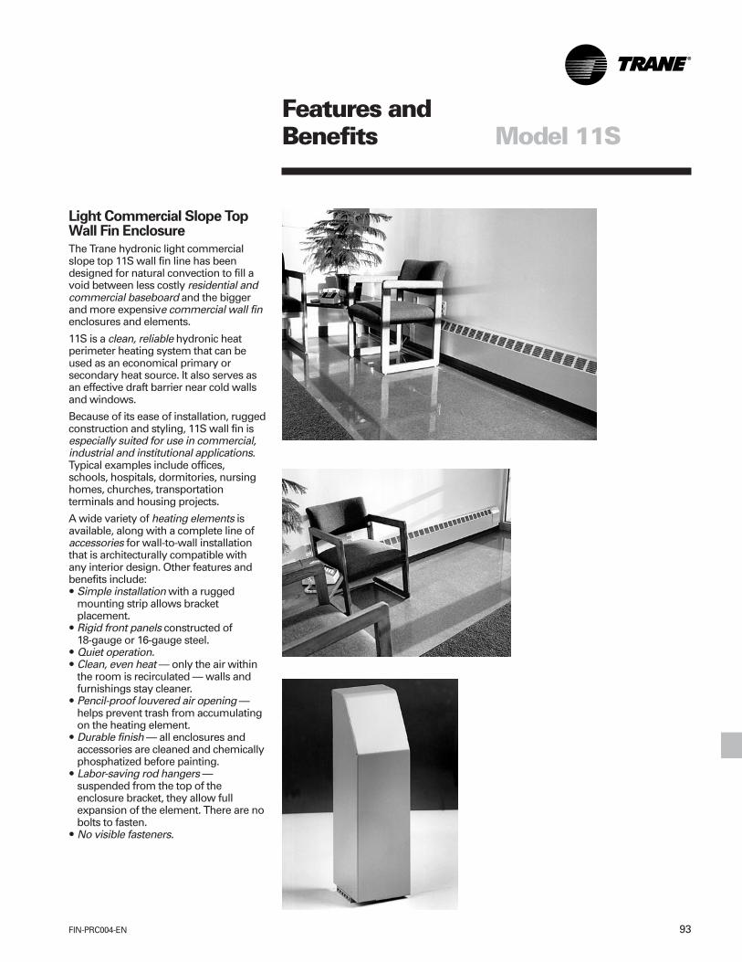
93FIN-PRC004-EN
Light Commercial Slope TopWall Fin Enclosure
The Trane hydronic light commercialslope top 11S wall fin line has beendesigned for natural convection to fill avoid between less costly residential andcommercial baseboard and the biggerand more expensive commercial wall finenclosures and elements.
11S is a clean, reliable hydronic heatperimeter heating system that can beused as an economical primary orsecondary heat source. It also serves asan effective draft barrier near cold wallsand windows.
Because of its ease of installation, ruggedconstruction and styling, 11S wall fin isespecially suited for use in commercial,industrial and institutional applications.Typical examples include offices,schools, hospitals, dormitories, nursinghomes, churches, transportationterminals and housing projects.
A wide variety of heating elements isavailable, along with a complete line ofaccessories for wall-to-wall installationthat is architecturally compatible withany interior design. Other features andbenefits include:• Simple installation with a rugged
mounting strip allows bracketplacement.
• Rigid front panels constructed of18-gauge or 16-gauge steel.
• Quiet operation.• Clean, even heat — only the air within
the room is recirculated — walls andfurnishings stay cleaner.
• Pencil-proof louvered air opening —helps prevent trash from accumulatingon the heating element.
• Durable finish — all enclosures andaccessories are cleaned and chemicallyphosphatized before painting.
• Labor-saving rod hangers —suspended from the top of theenclosure bracket, they allow fullexpansion of the element. There are nobolts to fasten.
• No visible fasteners.
Features andBenefits Model 11S

FIN-PRC004-EN94
Features andBenefits Model 11S
6” (152 mm) End Cap6” (152 mm) End Cap With Access Door
6” (152 mm) Wall Trim 8” (203 mm) Valve Compartment
Inside Corner

95FIN-PRC004-EN
14” (356 mm) Fill-In Section
Outside Corner2” (51 mm) Splice Plate
Features andBenefits Model 11S

FIN-PRC004-EN96
PerformanceandGeneral Data
Model 11SEnglish Units
Table PD-1 — Copper/Aluminum Elements — Btu/Hour/Foot
Steam11S Rating Hot Water (Ave.)
Copper/Aluminum Elements Encl. 215°F 220°F 210°F 200°F 190°F 180°F 170°F 160°F 150°F 140°F 130°FTube Fin Size Fins/ Fin Mtg.(2) Factor FactorSize Inches Foot Thickness Height 1.00 1.05 0.95 0.86 0.78 0.69 0.61 0.53 0.45 0.40 0.33
(3) 3/4” 2 1/4 x 2 1/2 50 0.011” 14 1/4” 1080 1130 1020 930 840 750 660 570 490 530 360(3) 3/4” 2 3/4 x 2 1/2 55 0.011” 14 1/4” 1140 1195 1080 980 890 785 695 605 515 455 375*3/4” 2 3/4 x 3 3/4 50 0.011” 14 1/4” 1170 1225 1110 1010 915 810 715 620 530 465 385(3) 1” 2 3/4 x 2 1/2 55 0.011” 14 1/4” 1090 1145 1035 935 850 755 665 575 490 435 3601” 2 3/4 x 3 3/4 50 0.011” 14 1/4” 1130 1185 1075 970 880 780 690 600 510 450 3701” 2 3/4 x 5 40 0.020” 14 1/4” 1200 1260 1140 1030 935 830 730 630 540 480 395*1” 2 3/4 x 5 50 0.020” 14 1/4” 1210 1270 1150 1040 945 835 740 645 545 485 4001 1/4” 2 3/4 x 3 3/4 50 0.020” 14 1/4” 1150 1210 1095 990 895 795 700 610 515 460 380*1 1/4” 2 3/4 x 5 40 0.020” 14 1/4” 1150 1210 1095 990 895 795 700 610 515 460 3801 1/4” 2 3/4 x 5 50 0.020” 14 1/4” 1230 1290 1170 1060 960 850 750 655 555 490 405
1. * I=B=R Rating on assemblies as marked.2. Mounting height is the dimension from the floor to the center of the outlet grille to obtain listed capacities.3. Two-tier applications can only be used with the 3/4” and 1”’ CA elements with 2 3/4” x 2 1/2” size fins.
Table PD-2 — Steel Tube/Fin Elements — Btu/Hour/Foot
Steam11S Rating Hot Water (Ave.)
Steel Tube/Fin Elements Encl. 215°F 220°F 210°F 200°F 190°F 180°F 170°F 160°F 150°F 140°F 130°FTube Fin Size Fins/ Fin Mtg.(2) Factor FactorSize Inches Foot Thickness Height 1.00 1.05 0.95 0.86 0.78 0.69 0.61 0.53 0.45 0.40 0.33*1” 2 3/4 x 3 3/4 40 0.024” 14 1/4” 910 955 865 785 710 630 555 485 410 365 3001” 2 3/4 x 5 40 0.024” 14 1/4” 910 955 865 785 710 630 555 485 410 365 300
1 1/4” 2 3/4 x 5 40 0.024” 14 1/4” 930 975 885 800 725 625 570 495 420 370 3051. * I=B=R Rating on assemblies as marked.2. Mounting height is the dimension from the floor to the center of the outlet grille to obtain listed capacities.
Table PD-3 — Copper/Aluminum Elements — Btu/Hour/Foot— Two Tiers
Steam11S Rating Hot Water (Ave.)
Copper/Aluminum Elements Encl. 215°F 220°F 210°F 200°F 190°F 180°F 170°F 160°F 150°F 140°F 130°FTube Fin Size Fins/ Fin Mtg.(1) Factor FactorSize Inches Foot Thickness Height 1.00 1.05 0.95 0.86 0.78 0.69 0.61 0.53 0.45 0.40 0.333/4” 2 3/4 x 2 1/2 55 0.011” 14 1/4” 1560 1640 1480 1340 1220 1080 950 830 700 620 5101” 2 3/4 x 2 1/2 55 0.011” 14 1/4” 1600 1680 1520 1380 1250 1100 980 850 720 640 530
1. Mounting height is the dimension from the floor to the center of the outlet grille to obtain listed capacities.2. Capacities based on two tiers of element mounted on 3 1/2” (89 mm) centers.

97FIN-PRC004-EN
PerformanceandGeneral Data
Model 11SSI Units
Table PD-4 — Copper/Aluminum Elements — Watts/Meter
Steam11S Rating Hot Water (Ave.)
Copper/Aluminum Elements Encl. 102°C 104°C 99°C 93°C 88°C 82°C 77°C 71°C 66°C 60°C 54°CTube Fin Size Fins/ Fin Mtg.(2) Factor FactorSize Millimeters Meter Thickness Height 1.00 1.05 0.95 0.86 0.78 0.69 0.61 0.53 0.45 0.40 0.33
(3) 19 mm 57 x 64 164 0.28 mm 362 mm 1040 1090 990 890 810 720 630 550 470 415 340(3) 19 mm 70 x 64 180 0.28 mm 362 mm 1095 1150 1035 940 855 755 665 580 495 435 360*19 mm 70 x 95 164 0.28 mm 362 mm 1125 1175 1065 970 880 775 685 595 510 445 370(3) 25 mm 70 x 64 180 0.28 mm 362 mm 1050 1100 995 900 815 725 640 550 470 415 34525 mm 70 x 95 164 0.28 mm 362 mm 1085 1140 1035 930 845 750 665 575 490 430 35525 mm 70 x 127 131 0.51 mm 362 mm 1155 1210 1045 990 900 800 700 605 520 460 380*25 mm 70 x 127 164 0.51 mm 362 mm 1165 1220 1105 1000 910 800 710 620 525 465 38532 mm 70 x 95 164 0.51 mm 362 mm 1105 1165 1050 950 860 765 670 585 495 440 365*32 mm 70 x 127 131 0.51 mm 362 mm 1105 1165 1050 950 860 765 670 585 495 440 36532 mm 70 x 127 164 0.51 mm 362 mm 1180 1240 1125 1020 920 815 720 630 535 470 3901. * I=B=R Rating on assemblies as marked.2. Mounting height is the dimension from the floor to the center of the outlet grille to obtain listed capacities.3. Two-tier applications can only be used with the 19 mm and 25 mm CA elements with 70 x 64 mm size fins.
Table PD-5 — Steel Tube/Fin Elements — Watts/Meter
Steam11S Rating Hot Water (Ave.)
teel Tube/Fin Elements Encl. 102°C 104°C 99°C 93°C 88°C 82°C 77°C 71°C 66°C 60°C 54°CTube Fin Size Fins/ Fin Mtg.(2) Factor FactorSize Millimeters Meter Thickness Height 1.00 1.05 0.95 0.86 0.78 0.69 0.61 0.53 0.45 0.40 0.33
*25 mm 70 x 95 131 0.61 mm 362 mm 875 920 830 755 680 605 535 465 395 350 29025 mm 70 x 127 131 0.61 mm 362 mm 875 920 830 755 680 605 535 465 395 350 29032 mm 70 x 127 131 0.61 mm 362 mm 895 935 850 770 695 600 545 475 405 355 2951. * I=B=R Rating on assemblies as marked.2. Mounting height is the dimension from the floor to the center of the outlet grille to obtain listed capacities.
Table PD-6— Copper/Aluminum Elements — Watts/Meter — Two Tiers
SteamRating Hot Water (Ave.)
Copper/Aluminum Elements Encl. 102°C 104°C 99°C 93°C 88°C 82°C 77°C 71°C 66°C 60°C 54°CTube Fin Size Fins/ Fin Mtg.(2) Factor FactorSize Millimeters Meter Thickness Height 1.00 1.05 0.95 0.86 0.78 0.69 0.61 0.53 0.45 0.40 0.33
19 mm 70 x 64 180 0.28 mm 362 mm 1500 1580 1420 1290 1170 1040 910 800 670 600 49025 mm 70 x 64 180 0.28 mm 362 mm 1540 1610 1460 1330 1200 1060 940 820 690 620 5101. Mounting height is the dimension from the floor to the center of the outlet grille to obtain listed capacities.2. Capacities based on two tiers of element mounted on 3 1/2” (89 mm) centers.
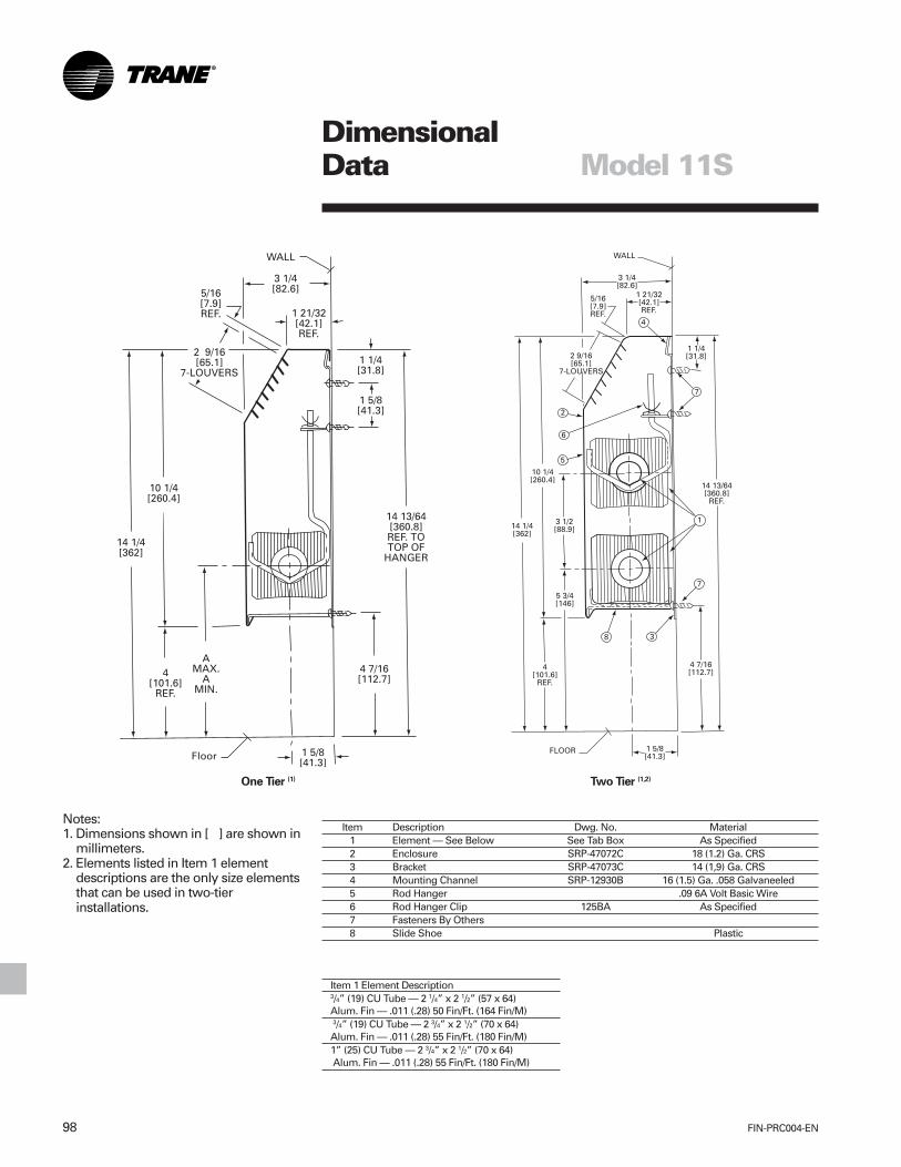
FIN-PRC004-EN98
DimensionalData Model 11S
Item Description Dwg. No. Material1 Element — See Below See Tab Box As Specified2 Enclosure SRP-47072C 18 (1.2) Ga. CRS3 Bracket SRP-47073C 14 (1,9) Ga. CRS4 Mounting Channel SRP-12930B 16 (1.5) Ga. .058 Galvaneeled5 Rod Hanger .09 6A Volt Basic Wire6 Rod Hanger Clip 125BA As Specified7 Fasteners By Others8 Slide Shoe Plastic
Notes:1. Dimensions shown in [ ] are shown in
millimeters.2. Elements listed in Item 1 element
descriptions are the only size elementsthat can be used in two-tierinstallations.
Item 1 Element Description3/4” (19) CU Tube — 2 1/4” x 2 1/2” (57 x 64)Alum. Fin — .011 (.28) 50 Fin/Ft. (164 Fin/M) 3/4” (19) CU Tube — 2 3/4” x 2 1/2” (70 x 64)Alum. Fin — .011 (.28) 55 Fin/Ft. (180 Fin/M)1” (25) CU Tube — 2 3/4” x 2 1/2” (70 x 64) Alum. Fin — .011 (.28) 55 Fin/Ft. (180 Fin/M)
One Tier (1) Two Tier (1,2)

99FIN-PRC004-EN
DimensionalData Model 11S
Accessories
6” (152 mm) End Without Access DoorRight Hand Shown — Left Hand Opposite
3” (76 mm) End With Optional Piping SlotRight Hand Shown — Left Hand Opposite
6” (152 mm) End With Access DoorRight Hand Shown — Left Hand Opposite
Valve Compartment Fill-In Section
90º Inside Corner
2” (51 mm) Splice Plate
90º Outside Corner

FIN-PRC004-EN100
Cover andAccessoryLayout Model 11S
Mou
ntin
g C
hann
el
End
Cap
Mou
ntin
g C
hann
el
Not
es:
1. E
nclo
sure
sec
tions
ava
ilabl
e in
follo
win
gst
anda
rd le
ngth
s:2’
(.61
m) t
hru
8’ (2
.4 m
) in
1” (.
3048
m)
incr
emen
ts.
2. D
imen
sion
s sh
own
in (
) are
inm
illim
eter
s.
101FIN-PRC004-EN
MechanicalSpecifications Model 11S
GeneralNatural convection light commercialslope top wall fin (Model 11S) shall befurnished to meet the specified capacity.Enclosure, heating elements,accessories, etc., shall be installed inaccordance with the manufacturer’srecommendations.
MountingHydronic light commercial slope top wallfin (Model 11S) shall be wall mounted3 1/2” (89 mm) to 4” (102 mm) above thefloor level to obtain catalog capacities.
EnclosureSloping top outlet. Enclosure top/frontpanel shall be of one piece, fabricatedfrom 18 gauge (1.2 mm thickness) steelfor strength and durability. The optional16 gauge (1.5 mm thickness) steel isavailable. The top/front panel shall bepainted with a commercial prime paintas standard. The enclosure shall be10 1/4” (260 mm) high and 3 1/4” (83 mm)deep. Available in 2' (.61 m), 3' (.91 m), 4'(1.2 m), 5' (1.5 m), 6' (1.8 m), 7' (2.1 m)and 8' (2.4 m) lengths.
Enclosure and Suspension SystemEnclosures without visible fasteners forheating elements shall be installed to acontinuous mounting channelmanufactured from 18 gauge (1.2 mmthickness) Galvanneal™ steel at the topwith the bottom of the front panelsecured to enclosure bracketsmanufactured from Galvanneal steel.
They are positioned underneath themounting channels, offset, and installedto the wall. Adjacent enclosures shall bebutt-fit and aligned together with 2”(51 mm) splice plates. Each enclosurebracket shall be furnished with a clipfastener to fasten an adjustable wirehanger to for mounting of the heatingelement.
Two-Tier Bracket System*A two-tier bracket system shall befurnished for installation of two rows ofheating elements. An U-cradle shall befurnished to mount the first element tothe bottom of the enclosure bracket anda shorter wire hanger to mount thesecond element to the top of theenclosure bracket
*For use with 3/4” (19.1 mm) CA heatingelements with 2 3/4” (70 mm) x 2 1/2”(64 mm) size fins only.
Return Pipe Hanger Bracket SystemA return pipe hanger bracket systemshall be furnished for installation of onerow of heating element and return pipe.An U-cradle shall be furnished to mountthe heating element to the bottom of theenclosure bracket and a short wirehanger to mount the return pipe to thetop of the enclosure bracket.
Back PanelThe back panel shall be manufacturedfrom 20 gauge (.91 mm thickness)galvanneal steel and shall be furnishedas an extension of the mounting channelin the same height and lengths as theenclosure.

FIN-PRC004-EN102
MechanicalSpecifications Model 11S
Heating ElementsCopper Tube-Aluminum Fin (CA)CA heating elements are constructed ofseamless copper tubing which has beenmechanically expanded into aluminumfins. One tube is swaged for end-to-endjoining. Fins are heat- reflecting andinterlocked for maximum performanceand optimum thermal contact. Sixdifferent combinations are available:3/4” (19 mm) CAFin Size: 2 1/4” x 2 1/2” (57 mm x 64 mm) x .011” (.28 mm)Fin Spacing: 50 fins per foot (164 fins per m)3/4” (19 mm) CAFin Size: 2 3/4” x 2 1/2” (70 mm x 64 mm) x .011” (.28 mm)Fin Spacing: 55 fins per foot (180 fins per m)
3/4” (19 mm) CAFin Size: 2 3/4” x 3 3/4” (70 mm x 95 mm) x .011” (.28 mm)Fin Spacing: 50 fins per foot (164 fins per m)
1” (25 mm) CAFin Size: 2 3/4” x 2 1/2” (70 mm x 64 mm) x .011” (.28 mm)Fin Spacing: 55 fins per foot (180 fins per m)
1” (25 mm) CAFin Size: 2 3/4” x 3 3/4” (70 mm x 95 mm) x .011” (.28 mm)Fin Spacing: 50 fins per foot (164 fins per m)
1” (25 mm) CAFin Size: 2 3/4” x 5” (70 mm x 127 mm) x .020” (.51 mm)Fin Spacing: 40 fins per foot (131 fins per m) or 50 fins per foot (164 fins per m)
1 1/4” (32 mm) CAFin Size: 2 3/4” x 3 3/4” (70 mm x 95 mm) x .020” (.51 mm)Fin Spacing: 50 fins per foot (164 fins per m)
1 1/4” (32 mm) CAFin Size: 2 3/4” x 3 3/4” (70 mm x 95 mm) x .020” (.51 mm)Fin Spacing: 50 fins per foo (164 fins per m)
1 1/4” (32 mm) CAFin Size: 2 3/4” x 5” (70 mm x 127 mm) x .020” (.51 mm)Fin Spacing: 40 fins per foot (131 fins per m) or 50 fins per foot (164 fins per m)
Heating ElementsSteel Tube-Steel FinsSteel tube-steel fin heating elements areconstructed of condenser tubing whichhas been mechanically expanded intosteel fins. Tube ends are threaded andfurnished with NPT threads formaximum performance. The fins arepainted black.
1” I.P.S. (25 mm)Fin Size: 2 3/4” x 5” (70 mm x 127 mm) x .024 (.61 mm)Fin Spacing: 40 fins per foot (131 fins per m)
1” (25 m) and 1 1/4” (32 mm) I.P.S.Fin Size: 2 3/4” x 5” (70 mm x 127 mm) x .024 (.61 mm)Fin Spacing: 40 fins per foot (131 fins per m)
Heating Element LengthsThe heating element can be provided inlengths of :2’ (.61 m)3’ (0.91 m)4’ (1.2 m)5’ (1.5 m)6’ (1.8 m)7’ (2.1 m)8’ (2.4 m)
Accessories6” (152 mm) end panels with accessdoor3” (76 mm) and 6” (356) wall trims8” (152 mm) valve compartment14” (356 mm) fill-in section90 and 135 degree inside corners90 and 135 outside corners
Corners are overlapping and allow forcontinuous wall-to-wall installation.They are manufactured from 18 gauge(1.2 mm) thickness steel. All accessoriesare painted with a commercial primepaint as standard.
Color FinishThe top/front panels, splice plates andaccessories are available with bakedenamel color finishes (optional):Deluxe beigeSoft doveCameo whiteRose mauveStone greyDriftwood grey.


The Trane CompanyAn American Standard Companywww.trane.com
For more information contactyour local district office ore-mail us at [email protected]
Since The Trane Company has a policy of continuous product and product data improvement, it reserves theright to change design and specifications without notice.
Literature Order Number
File Number
Supersedes
Stocking Location
FIN-PRC004-EN
PL-RF-FIN-000-PRC004-1001
FIN-DS-1 4/98
La Crosse