Embed Size (px)
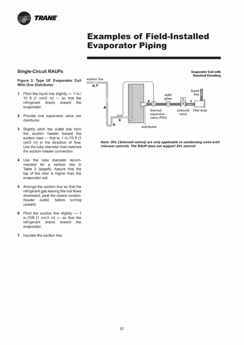
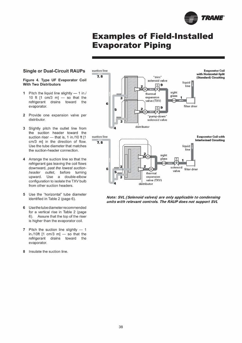
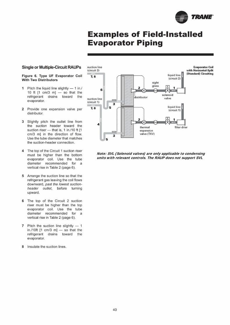
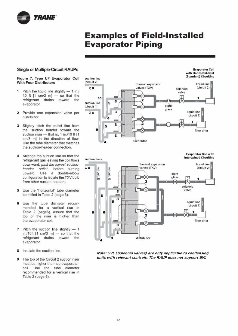
DESCRIPTION
HVAC
Citation preview
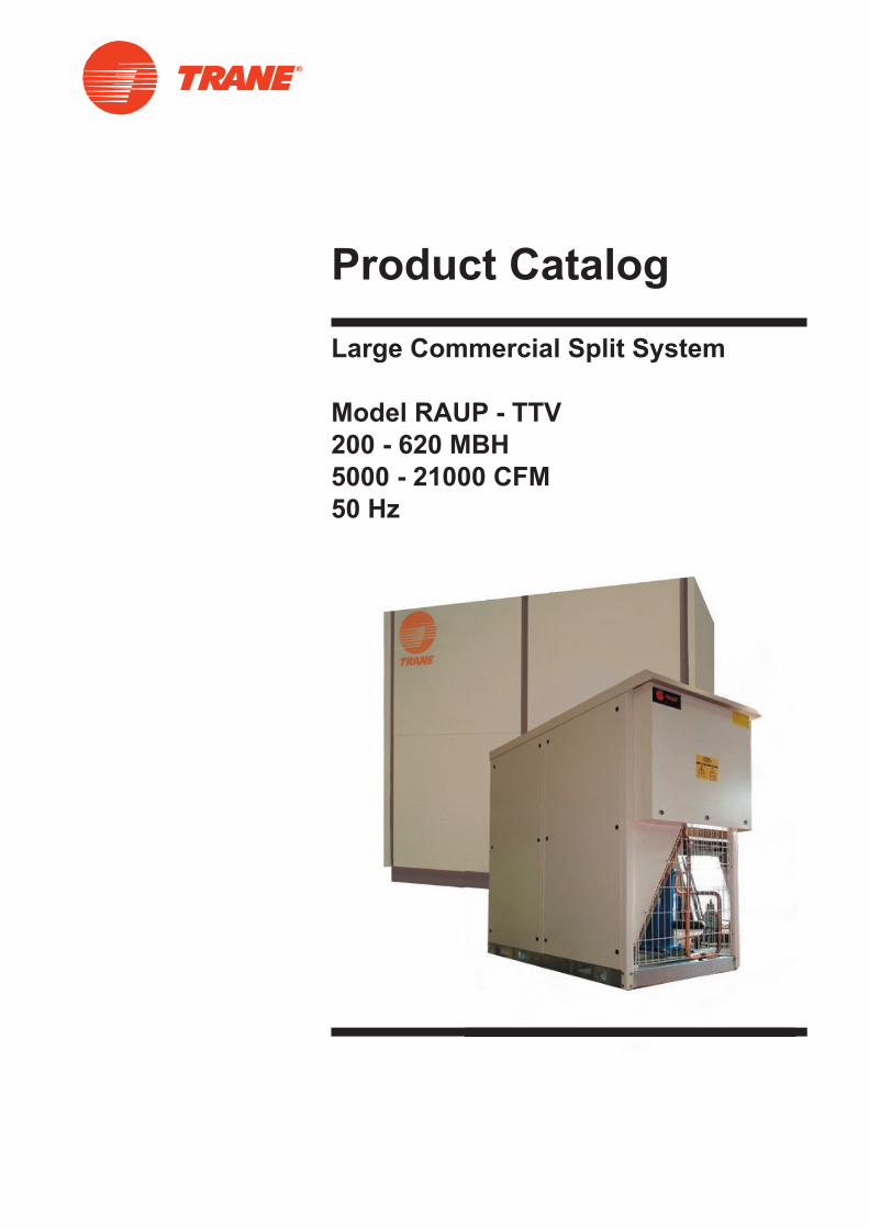
Product Catalog
Large Commercial Split System
Model RAUP - TTV
200 - 620 MBH
5000 - 21000 CFM
50 Hz
1
RAUP - TTVTABLE OF CONTENTS
2
3
4
5
6
7
8
9
13
21
29
30
31
32
34
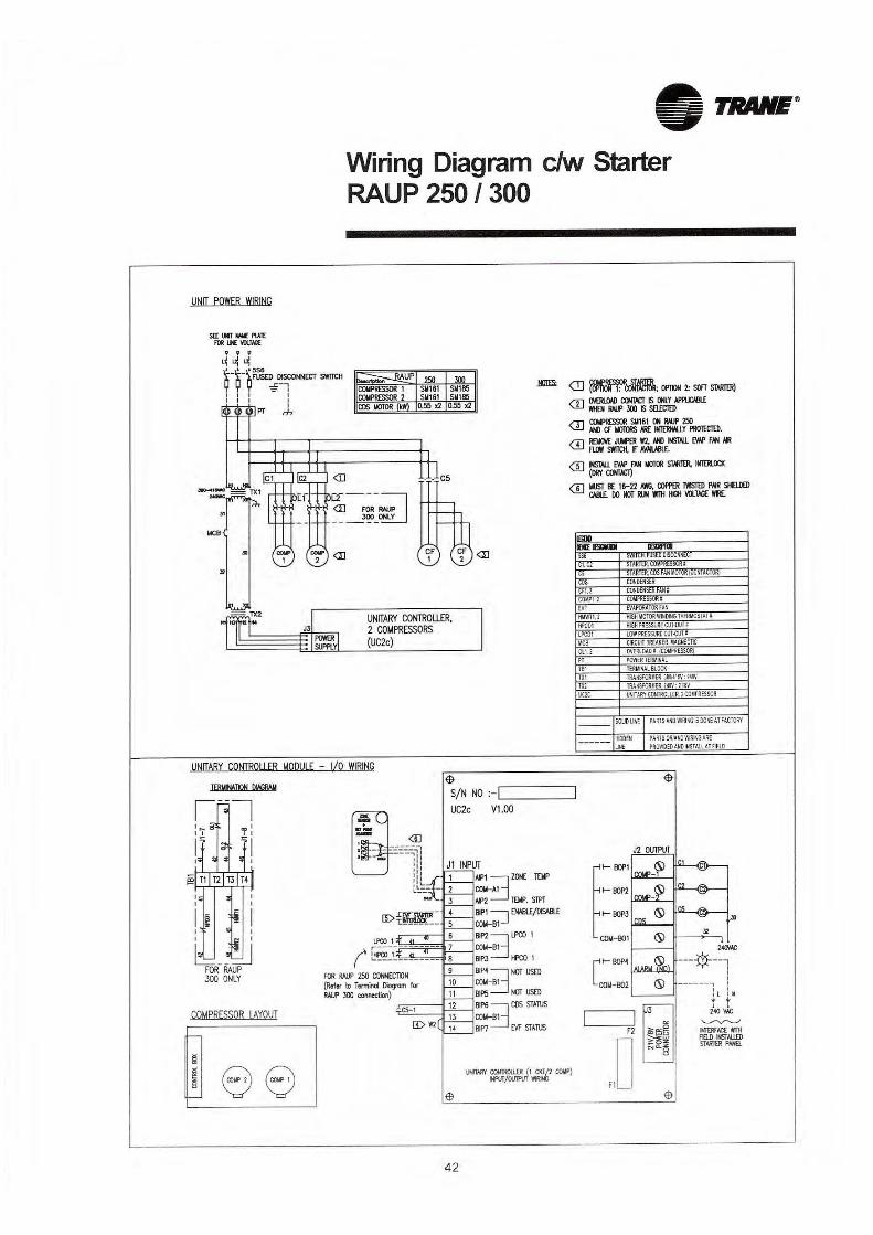
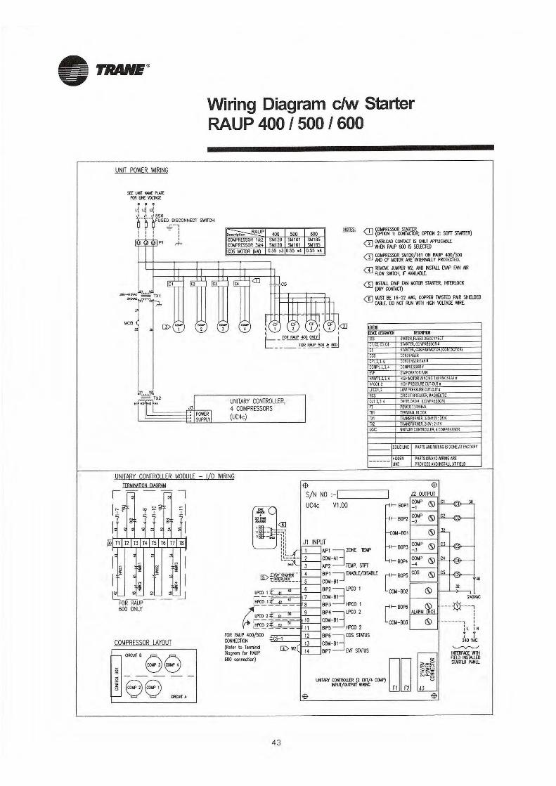
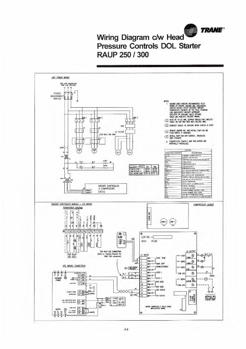
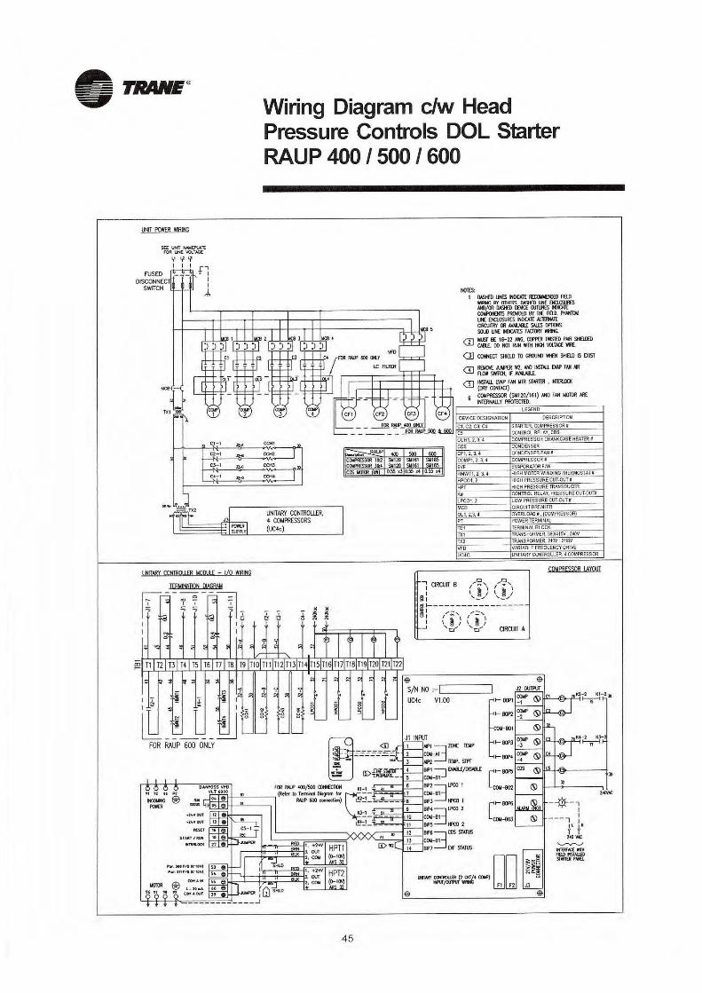
42
46
52
53
47
Model Number Description (RAUP-TTV)General Data 200-620 MBH Condensing UnitsGeneral Data Indoor UnitsSystem Performance MatrixFeatures SummaryQuantum Climate Changer Capacity ChartOutdoor Unit Application ConsiderationsEquipment SelectionRAUP Condensing Unit Performance R22RAUP Condensing Unit Performance R407CRAUP Performances Data-R22 (50Hz) - TableRAUP Performances Data-R407C (50Hz) - TableRAUP-TTV SystemIndoor Unit Fan Performance DataLine Sizing & PipingWiring DiagramsMechanical SpecificationsDimensional Drawing Condensing UnitDimensional Drawing Indoor UnitStandard Conversion Table

Standard Product Model Nomenclature
Model Number Description(Raup - TTV)
Unit Model Number DescriptionThe product is identified by a multiple-character model number that preciselyidentifies a particular type of unit. An explanation is shown below it will enablethe owner or Service Engineer to define operation, components and appli-cable accessories for a specific unit.
R A U P 2 5 0 D 1 C X A S 0 E1 2 3 4 5 6 7 8 9 10 11 12 13 14 15
DIGIT 1,2,3 Remote Condensing Unit / Air-Cooled / Up-Flow
DIGIT 4 Development Sequence
DIGIT 5,6,7 Nominal Cooling Capacity [MBH] 250 = 250 400 = 400 600 = 600 300 = 300 500 = 500
DIGIT 8 Electrical Rating / Utilization RangeD = 380-415V / 3Phase / 50Hz
DIGIT 9 Factory Mounted Control 1= DOL Starter with UC2c / UC4c. 4= DOL Starter with UC2c / UC4c c/w Low
Ambient Controls.
DIGIT 10 Minor Design SequenceC = Modular RAUP Design
DIGIT 11 Factory Installed Options X= None 1= Corrosion Resistant Coated Fin
DIGIT 12 Refrigerant Type A =R22 B = R407C
DIGIT 13 Operating Ambient S= Standard Ambient H= High Ambient Option
DIGIT 14 Future Use
DIGIT 15 Service IndicatorE = Introduction of Fuji Starter
T T V 2 5 0 Q D 1 D 0 0 0 A C1 2 3 4 5 6 7 8 9 10 11 12 13 14 15
DIGIT 1,2 Indoor Unit / Cooling Only
DIGIT 3 Air Flow ConfigurationV = Vertical Discharge
DIGIT 4,5,6 Nominal Cooling Capacity [MBH] 250 = 250 400 = 400 600 = 600 300 = 300 500 = 500
DIGIT 7 Development Sequence
DIGIT 8 Electrical Rating / Utilization RangeD = 380-415V / 3Phase / 50Hz
DIGIT 9 Factory Mounted Control1 = DOL Starter (less Controls)
DIGIT 10 Installed Motor kW
TTV Models Mtr , kW TTV 250 I = 3.7 TTV 300 / 400 K = 5.5 TTV 500 L = 7.5 TTV 600 M = 11
DIGIT 11 Future Use
DIGIT 12 Future Use
DIGIT 13 Future Use
DIGIT 14 Minor Design Sequence
DIGIT 15 Service Indicator
2
General Data 200 - 620 MBHCondensing Units
3
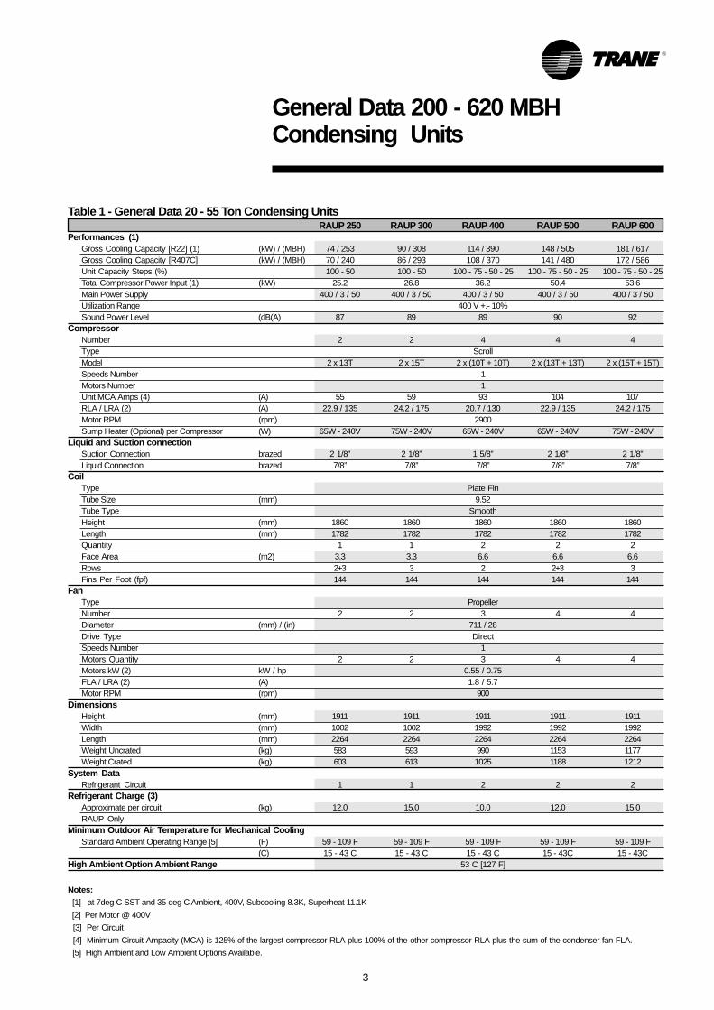
Table 1 - General Data 20 - 55 Ton Condensing UnitsRAUP 250 RAUP 300 RAUP 400 RAUP 500 RAUP 600
Performances (1)Gross Cooling Capacity [R22] (1) (kW) / (MBH) 74 / 253 90 / 308 114 / 390 148 / 505 181 / 617Gross Cooling Capacity [R407C] (kW) / (MBH) 70 / 240 86 / 293 108 / 370 141 / 480 172 / 586Unit Capacity Steps (%) 100 - 50 100 - 50 100 - 75 - 50 - 25 100 - 75 - 50 - 25 100 - 75 - 50 - 25Total Compressor Power Input (1) (kW) 25.2 26.8 36.2 50.4 53.6Main Power Supply 400 / 3 / 50 400 / 3 / 50 400 / 3 / 50 400 / 3 / 50 400 / 3 / 50Utilization Range 400 V +.- 10%Sound Power Level (dB(A) 87 89 89 90 92
CompressorNumber 2 2 4 4 4Type ScrollModel 2 x 13T 2 x 15T 2 x (10T + 10T) 2 x (13T + 13T) 2 x (15T + 15T)Speeds Number 1Motors Number 1Unit MCA Amps (4) (A) 55 59 93 104 107RLA / LRA (2) (A) 22.9 / 135 24.2 / 175 20.7 / 130 22.9 / 135 24.2 / 175Motor RPM (rpm) 2900Sump Heater (Optional) per Compressor (W) 65W - 240V 75W - 240V 65W - 240V 65W - 240V 75W - 240V
Liquid and Suction connectionSuction Connection brazed 2 1/8” 2 1/8” 1 5/8” 2 1/8” 2 1/8”Liquid Connection brazed 7/8” 7/8” 7/8” 7/8” 7/8”
CoilType Plate FinTube Size (mm) 9.52Tube Type SmoothHeight (mm) 1860 1860 1860 1860 1860Length (mm) 1782 1782 1782 1782 1782Quantity 1 1 2 2 2Face Area (m2) 3.3 3.3 6.6 6.6 6.6Rows 2+3 3 2 2+3 3Fins Per Foot (fpf) 144 144 144 144 144
FanType PropellerNumber 2 2 3 4 4Diameter (mm) / (in) 711 / 28Drive Type DirectSpeeds Number 1Motors Quantity 2 2 3 4 4Motors kW (2) kW / hp 0.55 / 0.75FLA / LRA (2) (A) 1.8 / 5.7Motor RPM (rpm) 900
DimensionsHeight (mm) 1911 1911 1911 1911 1911Width (mm) 1002 1002 1992 1992 1992Length (mm) 2264 2264 2264 2264 2264Weight Uncrated (kg) 583 593 990 1153 1177Weight Crated (kg) 603 613 1025 1188 1212
System DataRefrigerant Circuit 1 1 2 2 2
Refrigerant Charge (3)Approximate per circuit (kg) 12.0 15.0 10.0 12.0 15.0RAUP Only
Minimum Outdoor Air Temperature for Mechanical CoolingStandard Ambient Operating Range [5] (F) 59 - 109 F 59 - 109 F 59 - 109 F 59 - 109 F 59 - 109 F
(C) 15 - 43 C 15 - 43 C 15 - 43 C 15 - 43C 15 - 43CHigh Ambient Option Ambient Range 53 C [127 F]
Notes: [1] at 7deg C SST and 35 deg C Ambient, 400V, Subcooling 8.3K, Superheat 11.1K [2] Per Motor @ 400V [3] Per Circuit [4] Minimum Circuit Ampacity (MCA) is 125% of the largest compressor RLA plus 100% of the other compressor RLA plus the sum of the condenser fan FLA. [5] High Ambient and Low Ambient Options Available.
5
System Performance Matrix
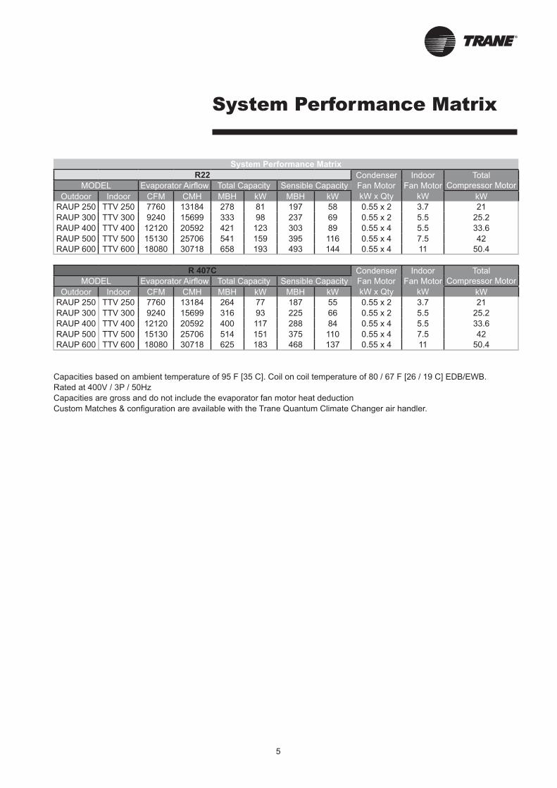
System Performance Matrix
R22 Condenser Indoor Total
MODEL Evaporator Airflow Total Capacity Sensible Capacity Fan Motor Fan Motor Compressor Motor
Outdoor Indoor CFM CMH MBH kW MBH kW kW x Qty kW kW
RAUP 250 TTV 250 7760 13184 278 81 197 58 0.55 x 2 3.7 21
RAUP 300 TTV 300 9240 15699 333 98 237 69 0.55 x 2 5.5 25.2
RAUP 400 TTV 400 12120 20592 421 123 303 89 0.55 x 4 5.5 33.6
RAUP 500 TTV 500 15130 25706 541 159 395 116 0.55 x 4 7.5 42
RAUP 600 TTV 600 18080 30718 658 193 493 144 0.55 x 4 11 50.4
R 407C Condenser Indoor Total
MODEL Evaporator Airflow Total Capacity Sensible Capacity Fan Motor Fan Motor Compressor Motor
Outdoor Indoor CFM CMH MBH kW MBH kW kW x Qty kW kW
RAUP 250 TTV 250 7760 13184 264 77 187 55 0.55 x 2 3.7 21
RAUP 300 TTV 300 9240 15699 316 93 225 66 0.55 x 2 5.5 25.2
RAUP 400 TTV 400 12120 20592 400 117 288 84 0.55 x 4 5.5 33.6
RAUP 500 TTV 500 15130 25706 514 151 375 110 0.55 x 4 7.5 42
RAUP 600 TTV 600 18080 30718 625 183 468 137 0.55 x 4 11 50.4
Capacities based on ambient temperature of 95 F [35 C]. Coil on coil temperature of 80 / 67 F [26 / 19 C] EDB/EWB.
Rated at 400V / 3P / 50Hz
Capacities are gross and do not include the evaporator fan motor heat deduction
Custom Matches & configuration are available with the Trane Quantum Climate Changer air handler.
6
Features Summary
Features Summary
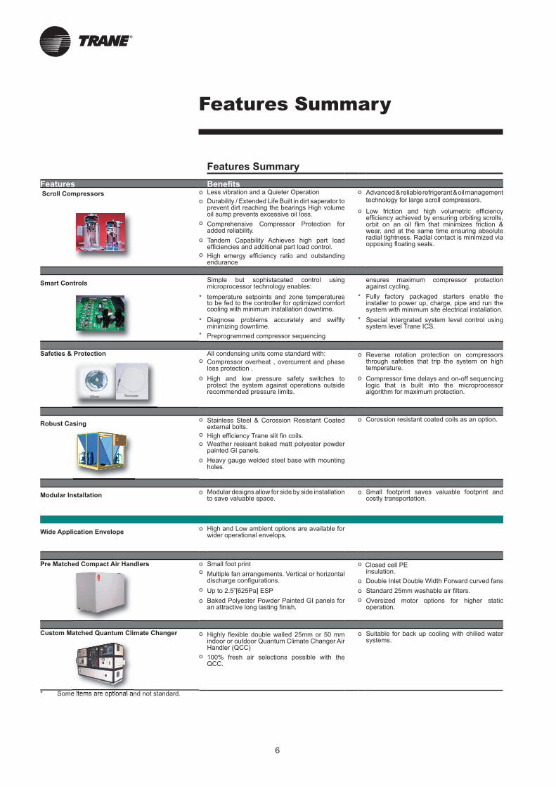
Features Benefi ts Scroll Compressors o Less vibration and a Quieter Operation o Advanced & reliable refrigerant & oil management
technology for large scroll compressors.o Durability / Extended Life Built in dirt saperator to prevent dirt reaching the bearings High volume oil sump prevents excessive oil loss.
o Low friction and high volumetric effi ciency effi ciency achieved by ensuring orbiting scrolls, orbit on an oil fl im that minimizes friction & wear, and at the same time ensuring absolute radial tightness. Radial contact is minimized via opposing fl oating seals.
o Comprehensive Compressor Protection for added reliability.
o Tandem Capability Achieves high part load effi ciencies and additional part load control.
o High emergy effi ciency ratio and outstanding endurance
Smart ControlsSimple but sophistacated control using microprocessor technology enables:
ensures maximum compressor protection against cycling.
* temperature setpoints and zone temperatures to be fed to the controller for optimized comfort cooling with minimum installation downtime.
* Fully factory packaged starters enable the installer to power up, charge, pipe and run the system with minimum site electrical installation.
* Diagnose problems accurately and swiftly minimizing downtime.
* Special intergrated system level control using system level Trane ICS.
* Preprogrammed compressor sequencing
Safeties & Protection All condensing units come standard with: o Reverse rotation protection on compressors through safeties that trip the system on high temperature.
o Compressor overheat , overcurrent and phase loss protection .
o High and low pressure safety switches to protect the system against operations outside recommended pressure limits.
o Compressor time delays and on-off sequencing logic that is built into the microprocessor algorithm for maximum protection.
Robust Casingo Stainless Steel & Corossion Resistant Coated
external bolts.o Corossion resistant coated coils as an option.
o High effi ciency Trane slit fi n coils.
o Weather resisant baked matt polyester powder painted GI panels.
o Heavy gauge welded steel base with mounting holes.
Modular Installationo Modular designs allow for side by side installation
to save valuable space.o Small footprint saves valuable footprint and
costly transportation.
Wide Application Envelopeo High and Low ambient options are available for
wider operational envelops.
Pre Matched Compact Air Handlers o Small foot print o Closed cell PE insulation.o Multiple fan arrangements. Vertical or horizontal
discharge confi gurations. o Double Inlet Double Width Forward curved fans
o Up to 2.5”[625Pa] ESP o Standard 25mm washable air fi lters.
o Baked Polyester Powder Painted GI panels for an attractive long lasting fi nish.
o Oversized motor options for higher static operation.
Custom Matched Quantum Climate Changer o Highly fl exible double walled 25mm or 50 mm indoor or outdoor Quantum Climate Changer Air Handler (QCC)
o Suitable for back up cooling with chilled water systems.
o 100% fresh air selections possible with the QCC.
* Some items are optional and not standard.
7
Quantum Climate Changer Capacity Chart
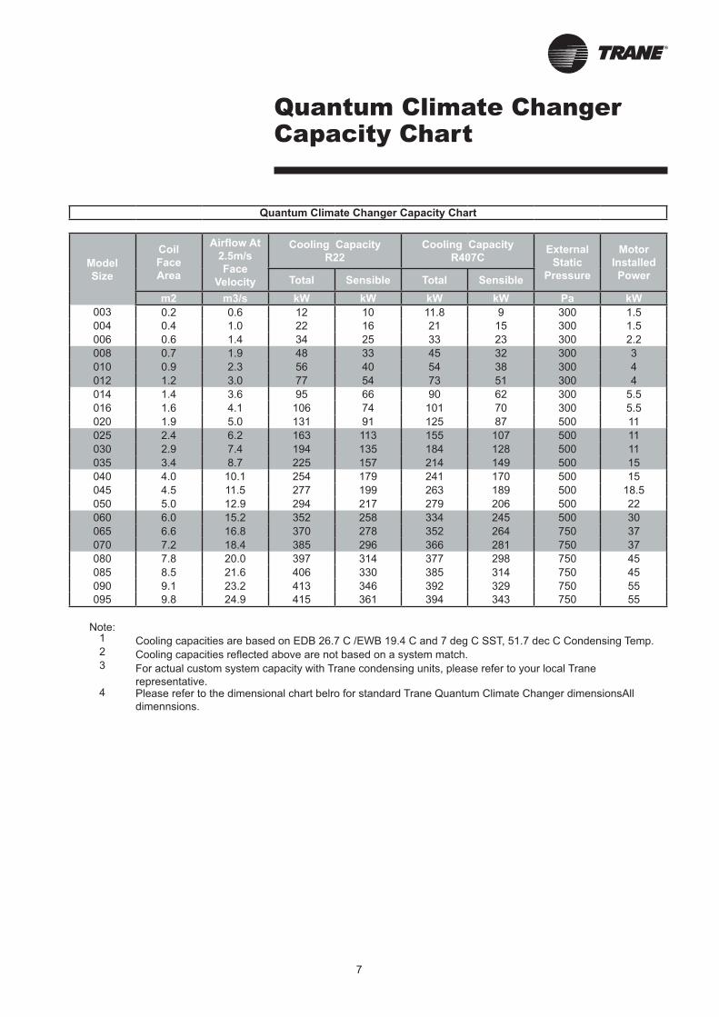
Quantum Climate Changer Capacity Chart
Model
Size
Coil
Face
Area
Airflow At
2.5m/s
Face
Velocity
Cooling Capacity
R22
Cooling Capacity
R407CExternal
Static
Pressure
Motor
Installed
PowerTotal Sensible Total Sensible
m2 m3/s kW kW kW kW Pa kW
003 0.2 0.6 12 10 11.8 9 300 1.5
004 0.4 1.0 22 16 21 15 300 1.5
006 0.6 1.4 34 25 33 23 300 2.2
008 0.7 1.9 48 33 45 32 300 3
010 0.9 2.3 56 40 54 38 300 4
012 1.2 3.0 77 54 73 51 300 4
014 1.4 3.6 95 66 90 62 300 5.5
016 1.6 4.1 106 74 101 70 300 5.5
020 1.9 5.0 131 91 125 87 500 11
025 2.4 6.2 163 113 155 107 500 11
030 2.9 7.4 194 135 184 128 500 11
035 3.4 8.7 225 157 214 149 500 15
040 4.0 10.1 254 179 241 170 500 15
045 4.5 11.5 277 199 263 189 500 18.5
050 5.0 12.9 294 217 279 206 500 22
060 6.0 15.2 352 258 334 245 500 30
065 6.6 16.8 370 278 352 264 750 37
070 7.2 18.4 385 296 366 281 750 37
080 7.8 20.0 397 314 377 298 750 45
085 8.5 21.6 406 330 385 314 750 45
090 9.1 23.2 413 346 392 329 750 55
095 9.8 24.9 415 361 394 343 750 55
Note:1 Cooling capacities are based on EDB 26.7 C /EWB 19.4 C and 7 deg C SST, 51.7 dec C Condensing Temp.2 Cooling capacities reflected above are not based on a system match.3 For actual custom system capacity with Trane condensing units, please refer to your local Trane
representative.4 Please refer to the dimensional chart belro for standard Trane Quantum Climate Changer dimensionsAll
dimennsions.
8
Outdoor Unit Application Considerations
Certain application constraints should
be considered when sizing, selecting
and installing Trane air-cooled
condensing units. Unit reliability is
dependent upon these considerations.
Where your application varies from
the guidelines presented, it should be
reviewed with the local Trane sales
engineer.
Unit Sizing
Intentionally oversizing a unit to
assure adequate capacity is not
recommended. Erratic system operation
and excessive compressor cycling are
often a direct result of an oversized
condensing unit. In addition,
oversized units are usually more
expensive to purchase, install and op-
erate. If oversizing is desired, consider
using two units.
Unit Placement
A base or foundation is not required if
the selected unit location is level and
strong enough to support the unit’s
operating weight.
Isolation and Sound Emission
The most effective form of isolation is
to locate the unit away from any sound
sensitive area. Structurally transmitted
sound can be reduced by using spring
or rubber isolators. The isolators are
effective in reducing the low frequency
sound generated by compressors and,
therefore are recommended for sound
sensitive installations. An acoustical
engineer should always be consulted
on critical applications. For maximum
isolation effect, the refrigeration lines
and electrical conduct should also be
isolated. Use flexible electrical
conduit. State and local codes on sound
emissions should always be consid-
ered. Since the environment in which a
sound source is located affects sound
pressure, unit placement must be care-
fully evaluated.
Unit Location
Unobstructed flow of condenser air is
essential for maintaining condensing
unit capacity and operating efficiency.
When determining unit placement,
careful consideration must be given
to assure proper air flow across the
condenser heat transfer surface.
Failure to heed these considerations
will result in warm air recirculation and
coil air flow starvation, resulting in a
high pressure compressor cutoff.
Warm air recirculation occurs when
discharge air from the condenser fans
is recycled back at the condenser coil
inlet. Coil starvation occurs when free
air flow to the condenser is restricted.
Both warm air recirculation and coil
starvation causes reductions in unit
efficiency and capacity. In addition,
in more severe cases, nuisance unit
shutdowns will result from excessive
head pressures. Accurate estimates
of the degree of efficiency and capacity
reduction are not possible due to the
unpredictable effect of varying winds,
temperatures and coil conditions.
In addition, wind tends to further reduce
head pressure. Therefore, it is
advisable to protect the air-cooled
condensing unit from continuous direct
winds exceeding 10 miles per hour.
Debris, trash, supplies, etc., should
not be allowed to accumulate in the
vicinity of the air-cooled condensing
unit. Supply air movement may draw
debris between coil fins and cause
coil starvation. Special consideration
should be given to units operating in
low ambient temperatures. Condenser
coils and fan discharge must be kept
free of snow and other obstructions to
permit adequate air flow for satisfactory
unit operation.
Effect of Altitude On Capacity
Condensing unit capacities given in the
performance data tables. At elevations
substantially above sea level, the
decreased air density will decrease
condenser capacity and efficiency.
The adjustment factors in Page 26
can be applied directly to the catalog
performance data to determine the
unit’s adjusted performance.
Ambient Considerations
Start up and operation at lower
ambients requires sufficient head
pressure be maintained for proper
expansion valve operation.
At higher ambients, excessive head
pressure may result. Standard operating
ambients are 15-43°C. With a low
ambient kit comprising crank case
heaters and frequency inverters,
operation below 15°C is achievable.
Minimum ambient condition are based
on still conditions.
Refrigerant Piping
Special consideration must always be
given to oil return. Minimum suction
gas velocities must always be
maintained for proper oil return. Utilize
appropriate piping tools lines sizing
such as the CDS refrigerant piping
program.
9
Equipment Selection
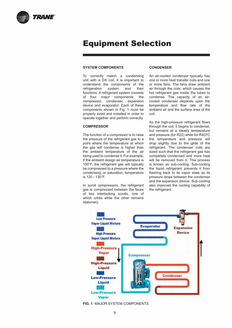
SYSTEM COMPONENTS
To correctly match a condensing
unit with a DX coil, it is important to
understand the components of the
refrigeration system and their
functions. A refrigerant system consists
of four major components: the
compressor, condenser, expansion
device and evaporator. Each of these
components shown in Fig. 1 must be
properly sized and installed in order to
operate together and perform correctly.
COMPRESSOR
The function of a compressor is to raise
the pressure of the refrigerant gas to a
point where the temperature at which
the gas will condense is higher than
the ambient temperature of the air
being used to condense it. For example,
if the ambient design air temperature is
100°F, the refrigerant gas will typically
be compressed to a pressure where the
condensing, or saturation, temperature
is 120 - 130°F.
In scroll cpmpressors, the refrigerant
gas is compressed between the faces
of two interlocking scrolls, one of
which orbits while the other remains
stationary.
CONDENSER
An air-cooled condenser typically has
one or more heat transfer coils and one
or more fans. The fans draw ambient
air through the coils, which causes the
hot refrigerant gas inside the tubes to
condense. The capacity of an air-
cooled condenser depends upon the
temperature and flow rate of the
ambient air and the surface area of the
coil.
As the high-pressure refrigerant flows
through the coil, it begins to condense,
but remains at a steady temperature
and pressure (for R22) while for R407C
the temperature and pressure will
drop slightly due to the glide of the
refrigerant. The condenser coils are
sized such that the refrigerant gas has
completely condensed and more heat
will be removed from it. This process
is known as sub-cooling. Sub-cooling
the liquid refrigerant prevents it from
flashing back to its vapor state as its
pressure drops between the condenser
and the expansion device. Sub-cooling
also improves the cooling capability of
the refrigerant.
FIG. 1 -MAJOR SYSTEM COMPONENTS

10
Equipment Selection
Horizontal Verticle Intertwined
Split Coils Split Coils Coils
FIG. 2 -EVAPORATOR COIL TYPES
EVAPORATOR
The evaporator coil removes heat
from the supply air-stream, cooling the
supply air in the process. The
evaporator coil generally consists
of several rows of copper tubing
mechanically bonded to aluminum (or
copper) heat transfer fins. Depending
on the size and capacity of the coil
it may consist of one, or several
refrigerant circuits (see Fig. 2).
A refrigerant distributor on each
DX evaporator coil circuit feeds low
pressure, low temperature liquid
refrigerant to the coil tubes. It is
critical that all the distributor tubes are
the same length so the pressure drop
across them will be equal and the
refrigerant will be evenly distributed to
the coil tubes.
refrigerant gas in the last row or two
of the coil tubes. The refrigerant gas
is superheated to ensure it does not
condense back to its liquid state in the
suction line. Superheat is also used to
control the expansion device.
EXPANSION DEVICE
The expansion device controls the flow
of liquid refrigerrant to the evaporator
coil. Trane uses temperature
controlled, (thermostatic) expansion
valves (TXVs) as shown in Fig. 3. The
TXV has two primary components: the
valve body and the sensing bulb.
The valve regulates the flow of refrigerant
to the evaporator coil. As refrigerant
passes through the valve it is
adiabatically expanded (that is, without
the addition of energy). This causes the
pressure and temperature of the liquid
refrigerant to drop, making it suitable
for cooling the air.
The amount of refrigerant fed to the
coil is based on the cooling load of the
supply air and the resultant amount
As the liquid refrigerant passes through
the coil tubes, heat is tranferred from
the supply air stream to the refrigerant.
As heat is added to the liquid
refrigerant, it begins to evaporate
much like water boiling on a stove. The
liquid-vapor mixture remains at a
constant temperature and pressure
until it completely vaporizes (for R22),
while for R407C the temperature and
pressure will drop slightly due to the
glide of the refrigerant. The coil capacity
is determined by the type and amount
of refrigerant used, the temperature
difference between the air and the
liquid refrigerant, and the amount of air
passing over the coil.
Once the refrigerant has completely
evaporated, its ability to cool the air
decrease dramatically. If too little
refrigerant is fed to the coil, it will
evaporate quickly and the air will not
be adequately cooled. If too much
refrigerant is fed to the coil it will not
evaporate at all and liquid refrigerant
will return to the compressor. Direct
expansion (DX) evaporator coils are
designed to evaporate all refrigerant
in the coil and then “superheat” the
FIG. 3 -THERMAL REXPANSION VALVE (TXV) COMPONENTS
Diaphragm
105ºF
210 psig
Liquid Line
Valve Body
Superheat
Adjustment
Screw (Set to 34 psig)
Superheat
Spring
63ºF
108 psig
46ºF
78 psig 59ºF, 74 psig
Superheated
Distributor
Equalizer Line
Evap. Coil
44ºF, 74 psig
Capillary
Tube
Sensing Bulb
59ºF, 100 psig
11
Equipment Selection
of superheat created. As the cooling load increases, the liquid refrigerant absorbs more heat and evaporates more quickly. This means that more of the evaporator coil is available to superheat the refrigerant vapor and it leaves the coil at a higher temperature.Conversely as the cooling load decreases, the liquid refrigerant does not evaporate as quickly so less superheating occurs and the refrigerant leaves the coil at a lower temperature.
The sensing bulb attached to the valve is charged with a mix of liquid and vapor refrigerant. This refrigerant must be the same type as that in the system. The refrigerant vapor in the sensing bulb exerts pressure on a diaphragm in the valve body, which causes the valve to open or close.
As the temperature of the superheatedsuction gas leaving the evaporatorrises due to an increase in the cooling load, refrigerant in the sensingbulb evaporates increasing the pressure on the valve diaphragm. The increased pressure causes the valve to open and allows more refrigerant to flow into the coil to meet the higher cooling demand. When the temperature of the suction gas drops due to a decrease in the cooling load, the gas in the sensing bulb condenses reducing its pressure on the valve diaphragm. This allows the valve to restrict the flow of refrigerantinto the coil until the lower coolingdemand is adequately met.
The valve body contains a superheat spring that keeps everything in balance. By turning a screw in the bottom of the valve the spring can be set for a certain amount of superheat. For example, if the superheat spring is set for 15 °F of superheat it will exert a pressure on thevalve equal to the pressure the vaporized gas in the sensing bulb will exert on the valve diaphragm when the suction gas is superheated by 15 °F. The equalizer line is used to prevent the pressure drop that occurs across the distributor and DX coil from affecting the operation of the expansion valve.
APPLICATION DESIGN CONDITIONS
Before selecting equipment, you must first establish these basic working pa-rameters: • The design cooling load • The design outdoor air temperature • The refrigerant saturated suction temperature
The design-cooling load is typically found on the job schedule. The design outdoor air temperature may also belisted on the job schedule. If the saturared suction temperature (SST) is not known, assume it is in the range of 40 °F to 45 °F. This represents the standard industry approach.
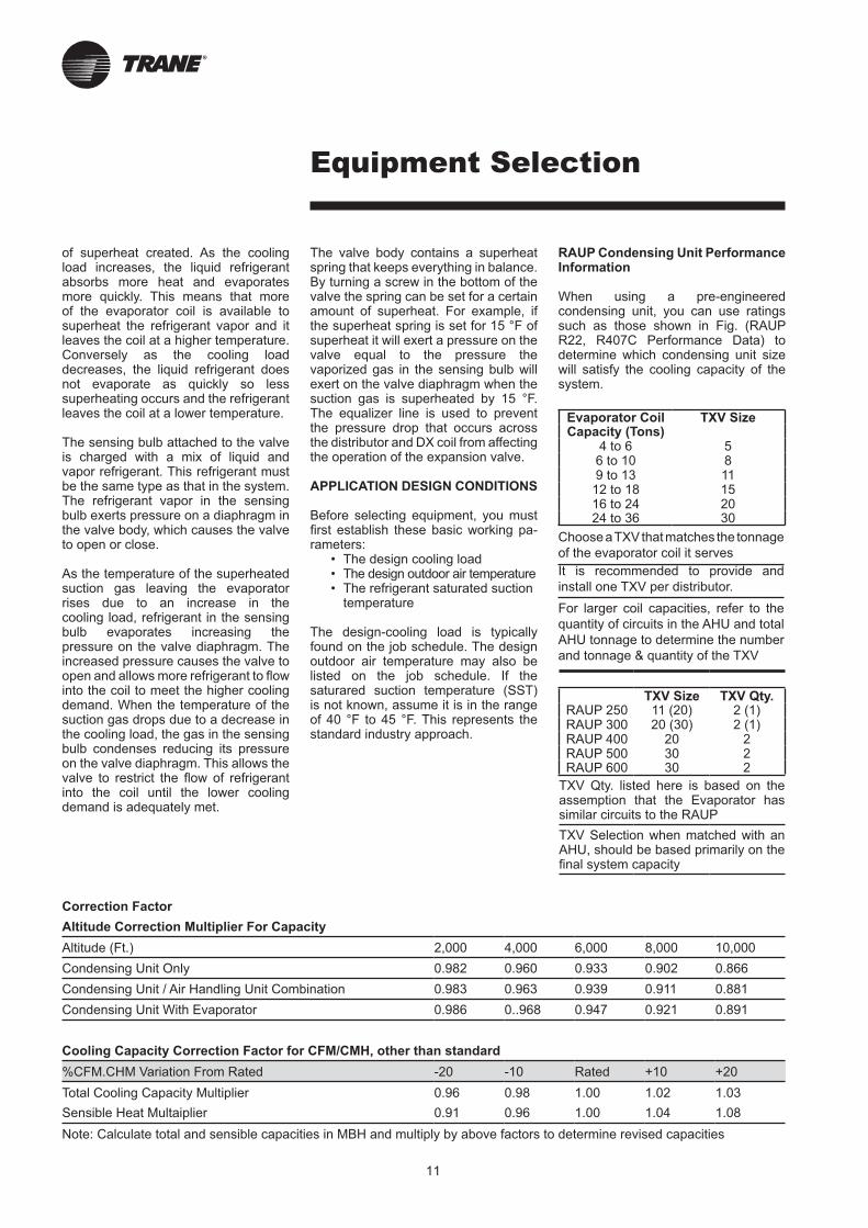
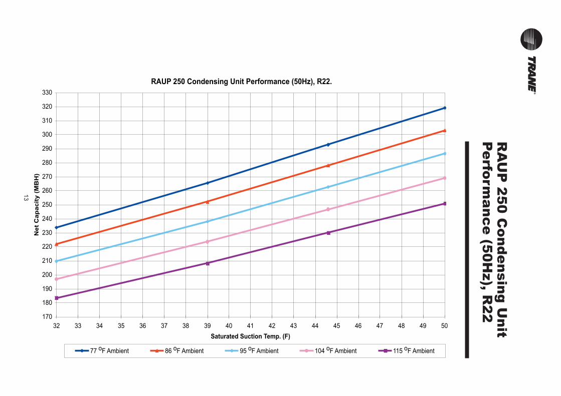
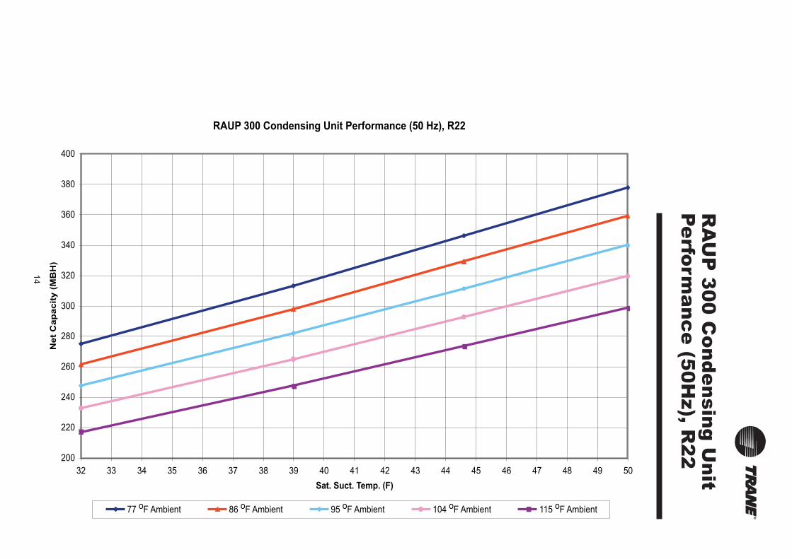
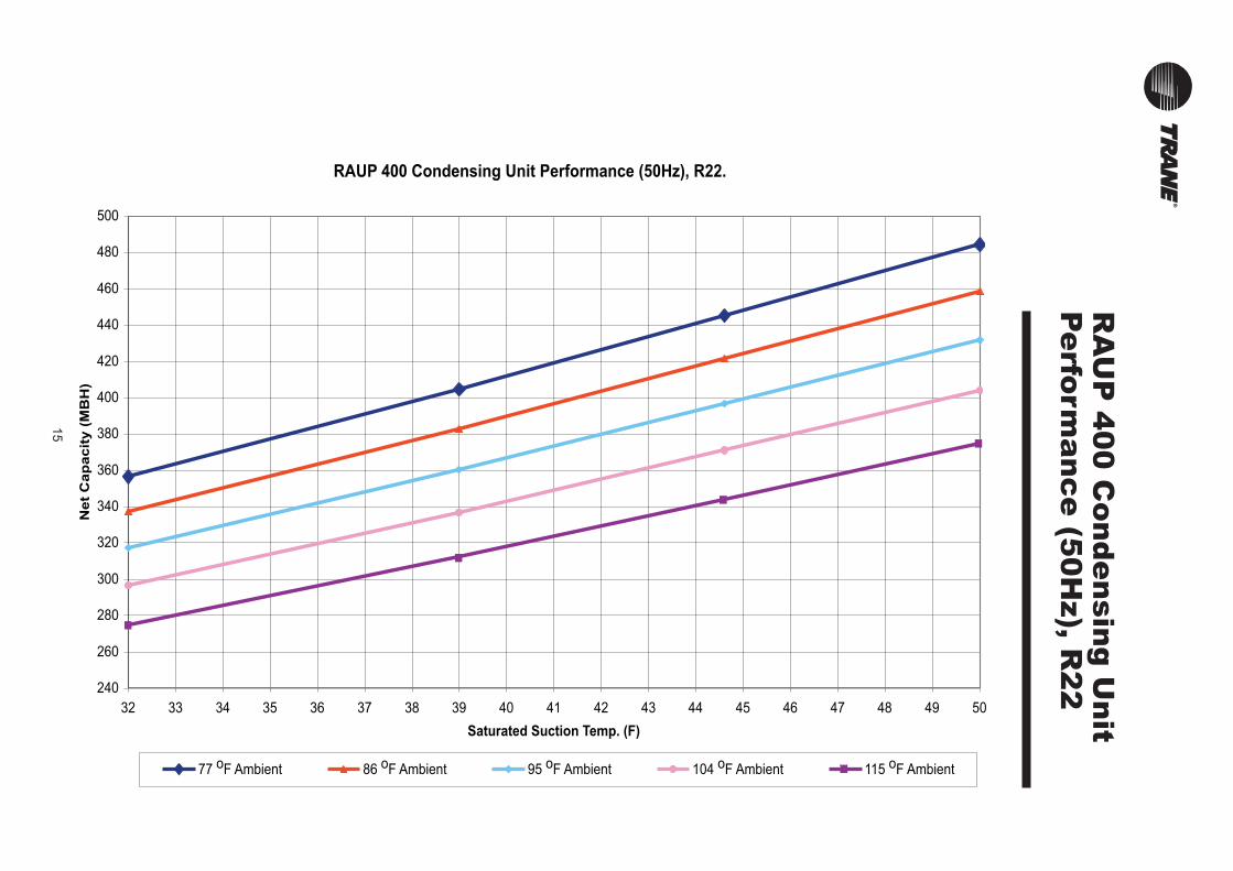
RAUP Condensing Unit Performance Information
When using a pre-engineered condensing unit, you can use ratings such as those shown in Fig. (RAUP R22, R407C Performance Data) to determine which condensing unit size will satisfy the cooling capacity of the system.
Evaporator Coil TXV SizeCapacity (Tons)
4 to 6 56 to 10 89 to 13 11
12 to 18 1516 to 24 2024 to 36 30
Choose a TXV that matches the tonnage
of the evaporator coil it serves
It is recommended to provide and
install one TXV per distributor.
For larger coil capacities, refer to the
quantity of circuits in the AHU and total
AHU tonnage to determine the number
and tonnage & quantity of the TXV
TXV Size TXV Qty.RAUP 250 11 (20) 2 (1)RAUP 300 20 (30) 2 (1)RAUP 400 20 2 RAUP 500 30 2RAUP 600 30 2
TXV Qty. listed here is based on the assemption that the Evaporator has similar circuits to the RAUP
TXV Selection when matched with an AHU, should be based primarily on the final system capacity
Correction Factor
Altitude Correction Multiplier For Capacity
Altitude (Ft.) 2,000 4,000 6,000 8,000 10,000
Condensing Unit Only 0.982 0.960 0.933 0.902 0.866
Condensing Unit / Air Handling Unit Combination 0.983 0.963 0.939 0.911 0.881
Condensing Unit With Evaporator 0.986 0..968 0.947 0.921 0.891
Cooling Capacity Correction Factor for CFM/CMH, other than standard
%CFM.CHM Variation From Rated -20 -10 Rated +10 +20
Total Cooling Capacity Multiplier 0.96 0.98 1.00 1.02 1.03
Sensible Heat Multaiplier 0.91 0.96 1.00 1.04 1.08
Note: Calculate total and sensible capacities in MBH and multiply by above factors to determine revised capacities
12
Equipment Selection
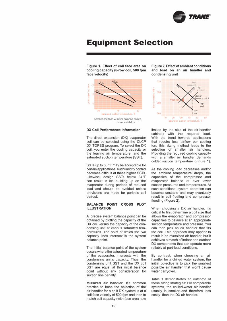
DX Coil Performance Information
The direct expansion (DX) evaporator coil can be selected using the CLCP DX TOPSS program. To select the DX coil, you enter the cooling capacity or the leaving air temperature, and the saturated suction temperature (SST).
SSTs up to 50 °F may be acceptable for certain applications, but humidity controlbecomes difficult at these higher SSTs. Likewise, design SSTs below 34°Fcan result in ice building up on the evaporator during periods of reduced load and should be avoided unless provisions are made for periodic coil defrost.
BALANCE POINT CROSS PLOT ILLUSTRATION
A precise system balance point can be obtained by plotting the capacity of the DX coil versus the capacity of the con-densing unit at various saturated tem-peratures. The point at which the two capacity lines intersect is the system balance point.
The initial balance point of the systemoccurs where the saturated temperature of the evaporator, intersects with thecondensing unit’s capacity. Thus, the condensing unit SST and the DX coil SST are equal at this initial balance point without any consideration for suction line penalty.
Missized air handler. It’s common practice to base the selection of the air handler for a split DX system is at a coil face velocity of 500 fpm and then to match coil capacity (with face area now
limited by the size of the air-handler cabinet) with the required load. With the trend towards applications that require less airflow per coolington, this sizing method leads to theselection of smaller air handlers.Providing the required cooling capacitywith a smaller air handler demands colder suction temperature (Figure 1).
As the cooling load decreases and/orthe ambient temperature drops, the capacities of the compressor and evaporator balance at ever lower suction pressures and temperatures. At such conditions, system operation can become unstable and may eventually result in coil frosting and compressor flooding (Figure 2).
When choosing a DX air handler, it’s critical to first determine a coil size that allows the evaporator and compressor capacities to balance at an appropriate suction temperature and pressure. You can then pick an air handler that fits the coil. This approach may appear to result in an oversized air handler, but it achieves a match of indoor and outdoor DX components that can operate more reliably at part-load conditions.
By contrast, when choosing an air handler for a chilled water system, the initial objective is to pick the smallest possible air handler that won’t cause water carryover.
Table 1 demonstrates an outcome of these sizing strategies: For comparable systems, the chilled-water air handler usually is smaller–and therefore less costly–than the DX air handler.
Figure 1. Effect of coil face area on
cooling capacity (6-row coil, 500 fpm
face velocity)
Figure 2. Effect of ambient conditions
and load on an air handler and
condensing unit
13
RA
UP
25
0 C
on
de
nsin
g U
nit
Pe
rform
an
ce
(50
Hz), R
22
RAUP 250 Condensing Unit Performance (50Hz), R22.
170
180
190
200
210
220
230
240
250
260
270
280
290
300
310
320
330
32 33 34 35 36 37 38 39 40 41 42 43 44 45 46 47 48 49 50
Saturated Suction Temp. (F)
Net
Cap
acit
y (
MB
H)
77 oF Ambient 86 oF Ambient 95 oF Ambient 104 oF Ambient 115 oF Ambient
14
RA
UP
30
0 C
on
de
nsin
g U
nit
Pe
rform
an
ce
(50
Hz), R
22
RAUP 300 Condensing Unit Performance (50 Hz), R22
200
220
240
260
280
300
320
340
360
380
400
32 33 34 35 36 37 38 39 40 41 42 43 44 45 46 47 48 49 50
Sat. Suct. Temp. (F)
Net
Cap
acit
y (
MB
H)
77 oF Ambient 86 oF Ambient 95 oF Ambient 104 oF Ambient 115 oF Ambient
15
RA
UP
40
0 C
on
de
nsin
g U
nit
Pe
rform
an
ce
(50
Hz), R
22
RAUP 400 Condensing Unit Performance (50Hz), R22.
240
260
280
300
320
340
360
380
400
420
440
460
480
500
32 33 34 35 36 37 38 39 40 41 42 43 44 45 46 47 48 49 50
Saturated Suction Temp. (F)
Net
Cap
acit
y (
MB
H)
77 oF Ambient 86 oF Ambient 95 oF Ambient 104 oF Ambient 115 oF Ambient
16
RA
UP
50
0 C
on
de
nsin
g U
nit
Pe
rform
an
ce
(50
Hz), R
22
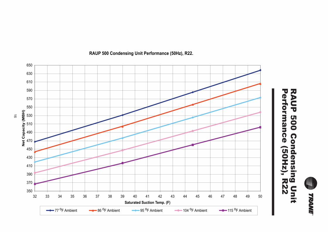
RAUP 500 Condensing Unit Performance (50Hz), R22.
350
370
390
410
430
450
470
490
510
530
550
570
590
610
630
650
32 33 34 35 36 37 38 39 40 41 42 43 44 45 46 47 48 49 50
Saturated Suction Temp. (F)
Net
Cap
acit
y (
MB
H)
77 oF Ambient 86 oF Ambient 95 oF Ambient 104 oF Ambient 115 oF Ambient

17
RA
UP
60
0 C
on
de
nsin
g U
nit
Pe
rform
an
ce
(50
Hz), R
22420
440
460
480
500
520
540
560
580
600
620
640
660
680
700
720
740
760
780
800
32 33 34 35 36 37 38 39 40 41 42 43 44 45 46 47 48 49 50
Saturated Suct. Temp. (F)
Net
Cap
acit
y (
MB
H)
77 oF Ambient 86 oF Ambient 95 oF Ambient 104 oF Ambient 115 oF Ambient
RAUP 600 Condensing Unit Performance (50Hz) R22.
18
RA
UP
40
0 x
2 C
on
de
nsin
g
Un
it Pe
rform
an
ce
(50
Hz)
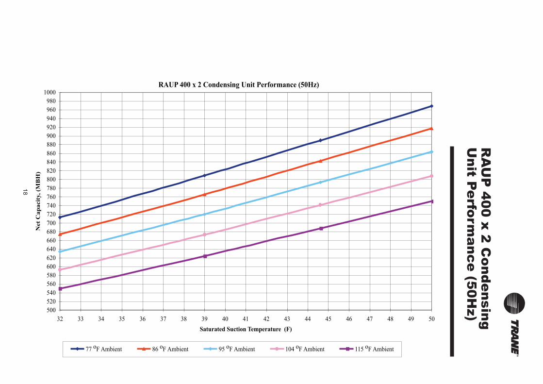
RAUP 400 x 2 Condensing Unit Performance (50Hz)
500
520
540
560
580
600
620
640
660
680
700
720
740
760
780
800
820
840
860
880
900
920
940
960
980
1000
32 33 34 35 36 37 38 39 40 41 42 43 44 45 46 47 48 49 50
Saturated Suction Temperature (F)
Net
Ca
pa
cit
y,
(MB
H)
77 oF Ambient 86 oF Ambient 95 oF Ambient 104 oF Ambient 115 oF Ambient

19
RA
UP
50
0 x
2 C
on
de
nsin
g
Un
it Pe
rform
an
ce
(50
Hz)
RAUP 500 x 2 Condensing Unit Performance (50Hz)
720
770
820
870
920
970
1020
1070
1120
1170
1220
1270
1320
32 34 36 38 40 42 44 46 48 50
77 oF Ambient 86 oF Ambient 95 oF Ambient 104 oF Ambient 115 oF Ambient
20
RA
UP
60
0 x
2 C
on
de
nsin
g
Un
it Pe
rform
an
ce
(50
Hz)
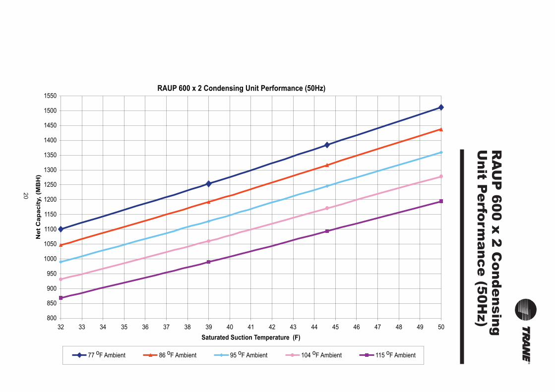
RAUP 600 x 2 Condensing Unit Performance (50Hz)
800
850
900
950
1000
1050
1100
1150
1200
1250
1300
1350
1400
1450
1500
1550
32 33 34 35 36 37 38 39 40 41 42 43 44 45 46 47 48 49 50
Saturated Suction Temperature (F)
Ne
t C
ap
ac
ity, (M
BH
)
77 oF Ambient 86 oF Ambient 95 oF Ambient 104 oF Ambient 115 oF Ambient
21
RA
UP
25
0 C
on
de
nsin
g U
nit
Pe
rform
an
ce
R4
07
C (5
0H
z)
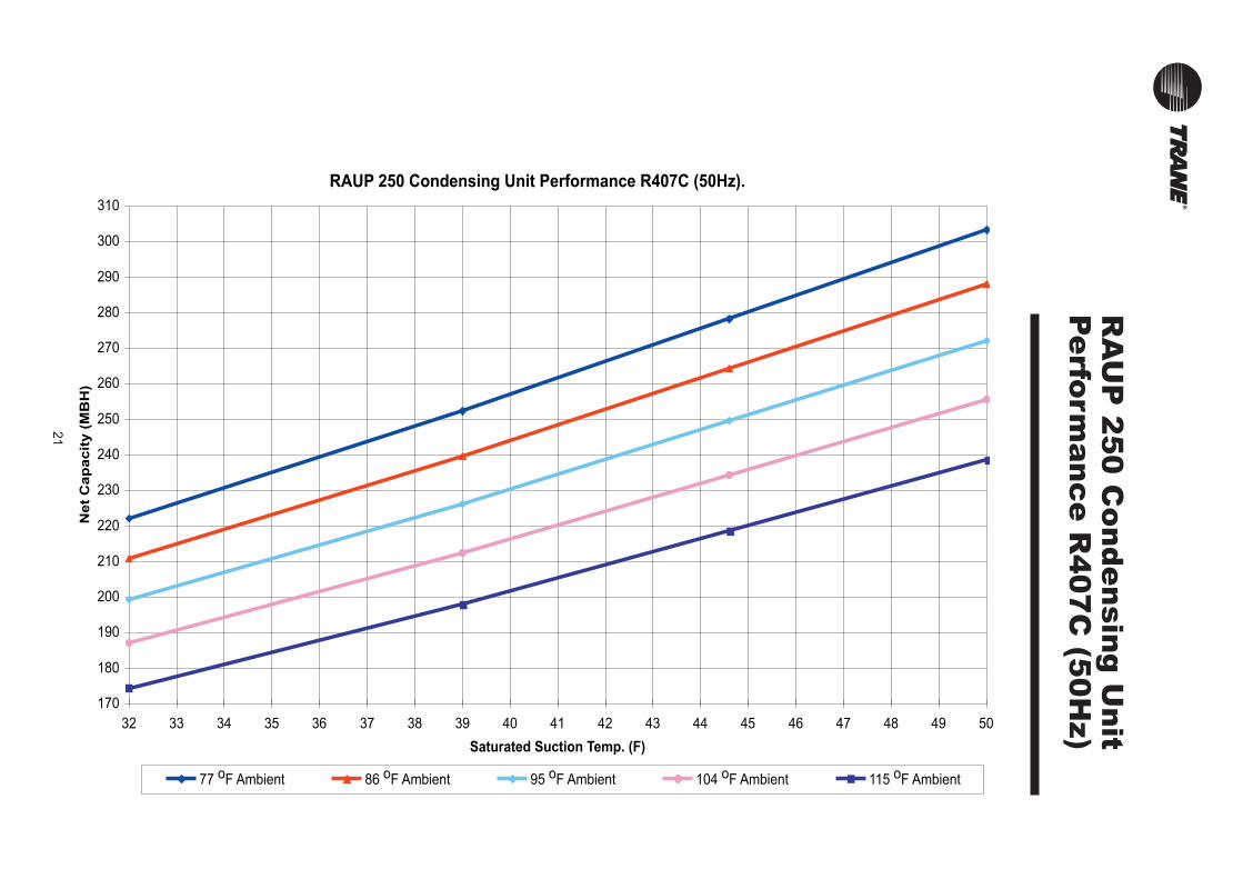
RAUP 250 Condensing Unit Performance R407C (50Hz).
170
180
190
200
210
220
230
240
250
260
270
280
290
300
310
32 33 34 35 36 37 38 39 40 41 42 43 44 45 46 47 48 49 50
Saturated Suction Temp. (F)
Net
Cap
acit
y (
MB
H)
77 oF Ambient 86 oF Ambient 95 oF Ambient 104 oF Ambient 115 oF Ambient

22
RA
UP
30
0 C
on
de
nsin
g U
nit
Pe
rform
an
ce
R4
07
C (5
0H
z)
RAUP 300 Condensing Unit Performance R407C (50 Hz)
200
220
240
260
280
300
320
340
360
380
400
32 33 34 35 36 37 38 39 40 41 42 43 44 45 46 47 48 49 50
Sat. Suct. Temp. (F)
Net
Cap
acit
y (
MB
H)
77 oF Ambient 86 oF Ambient 95 oF Ambient 104 oF Ambient 115 oF Ambient
23
RA
UP
40
0 C
on
de
nsin
g U
nit
Pe
rform
an
ce
R4
07
C (5
0H
z)
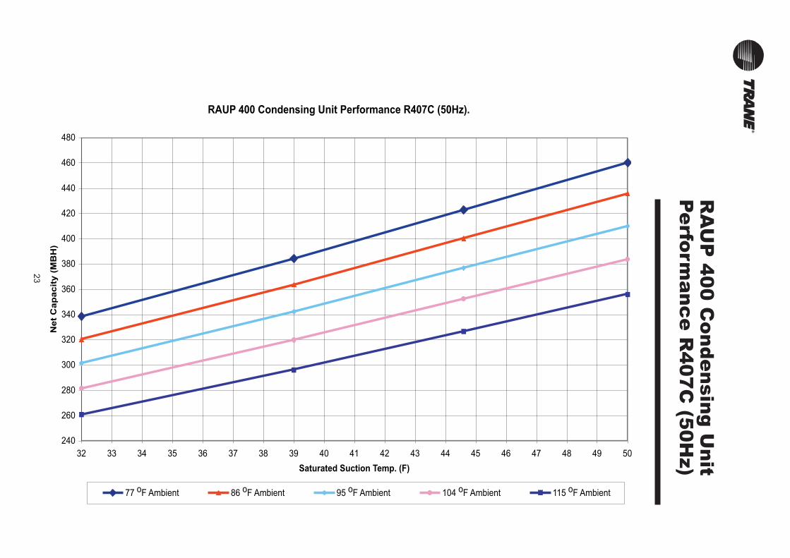
RAUP 400 Condensing Unit Performance R407C (50Hz).
240
260
280
300
320
340
360
380
400
420
440
460
480
32 33 34 35 36 37 38 39 40 41 42 43 44 45 46 47 48 49 50
Saturated Suction Temp. (F)
Net
Cap
acit
y (
MB
H)
77 oF Ambient 86 oF Ambient 95 oF Ambient 104 oF Ambient 115 oF Ambient

24
RA
UP
50
0 C
on
de
nsin
g U
nit
Pe
rform
an
ce
R4
07
C (5
0H
z)
RAUP 500 Condensing Unit Performance R407C (50Hz).
350
370
390
410
430
450
470
490
510
530
550
570
590
610
630
650
32 33 34 35 36 37 38 39 40 41 42 43 44 45 46 47 48 49 50
Saturated Suction Temp. (F)
Net
Cap
acit
y (
MB
H)
77 oF Ambient 86 oF Ambient 95 oF Ambient 104 oF Ambient 115 oF Ambient
25
RA
UP
60
0 C
on
de
nsin
g U
nit
Pe
rform
an
ce
R4
07
C (5
0H
z)
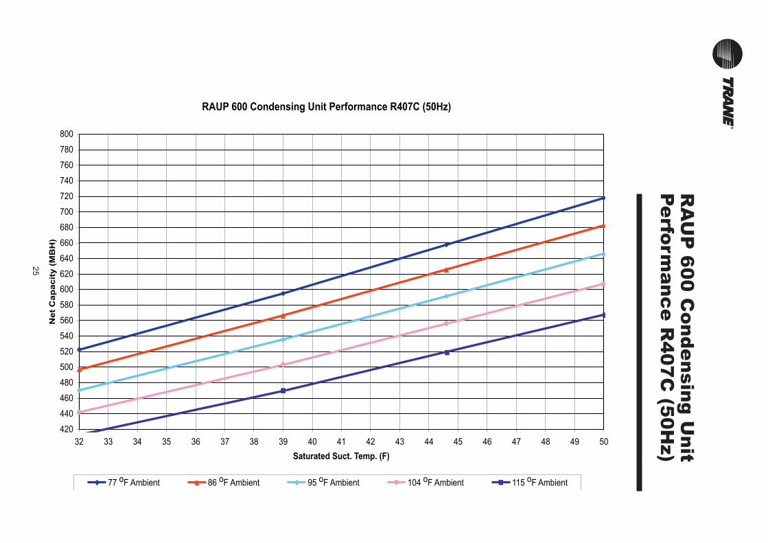
RAUP 600 Condensing Unit Performance R407C (50Hz)
420
440
460
480
500
520
540
560
580
600
620
640
660
680
700
720
740
760
780
800
32 33 34 35 36 37 38 39 40 41 42 43 44 45 46 47 48 49 50
Saturated Suct. Temp. (F)
Net
Cap
acit
y (
MB
H)
77 oF Ambient 86 oF Ambient 95 oF Ambient 104 oF Ambient 115 oF Ambient

26
RA
UP
40
0 x
2 C
on
de
nsin
g
Un
it Pe
rform
an
ce
R4
07
C (5
0H
z)
RAUP 400 x 2 Condensing Unit Performance R407C (50Hz)
500
520
540
560
580
600
620
640
660
680
700
720
740
760
780
800
820
840
860
880
900
920
940
960
980
1000
32 33 34 35 36 37 38 39 40 41 42 43 44 45 46 47 48 49 50
Saturated Suction Temperature (F)
Net
Ca
pa
cit
y,
(MB
H)
77 oF Ambient 86 oF Ambient 95 oF Ambient 104 oF Ambient 115 oF Ambient
27
RA
UP
50
0 x
2 C
on
de
nsin
g
Un
it Pe
rform
an
ce
R4
07
C (5
0H
z)
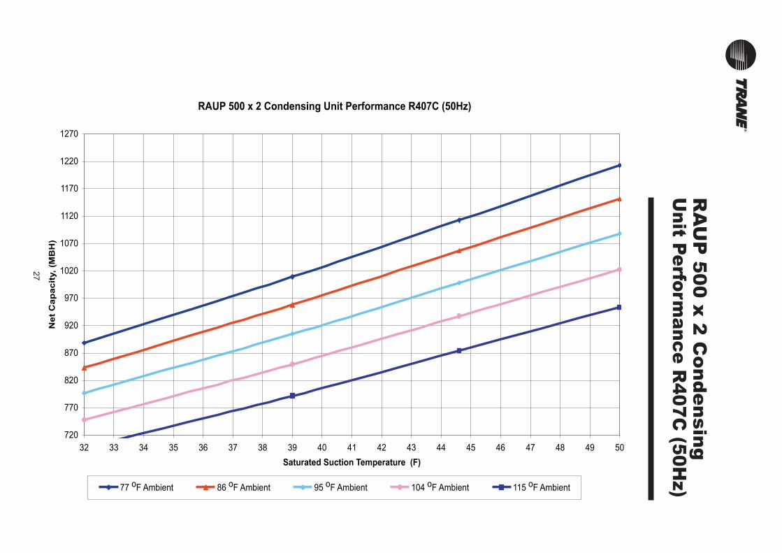
RAUP 500 x 2 Condensing Unit Performance R407C (50Hz)
720
770
820
870
920
970
1020
1070
1120
1170
1220
1270
32 33 34 35 36 37 38 39 40 41 42 43 44 45 46 47 48 49 50
Saturated Suction Temperature (F)
Net
Cap
acit
y, (M
BH
)
77 oF Ambient 86 oF Ambient 95 oF Ambient 104 oF Ambient 115 oF Ambient

28
RA
UP
60
0 x
2 C
on
de
nsin
g
Un
it Pe
rform
an
ce
R4
07
C (5
0H
z)
RAUP 600 x 2 Condensing Unit Performance R407C (50Hz)
800
850
900
950
1000
1050
1100
1150
1200
1250
1300
1350
1400
1450
1500
1550
32 33 34 35 36 37 38 39 40 41 42 43 44 45 46 47 48 49 50
Saturated Suction Temperature (F)
Ne
t C
ap
ac
ity, (M
BH
)
77 oF Ambient 86 oF Ambient 95 oF Ambient 104 oF Ambient 115 oF Ambient
29
RA
UP
Pe
rform
an
ce
Data
- R2
2 (5
0H
z)
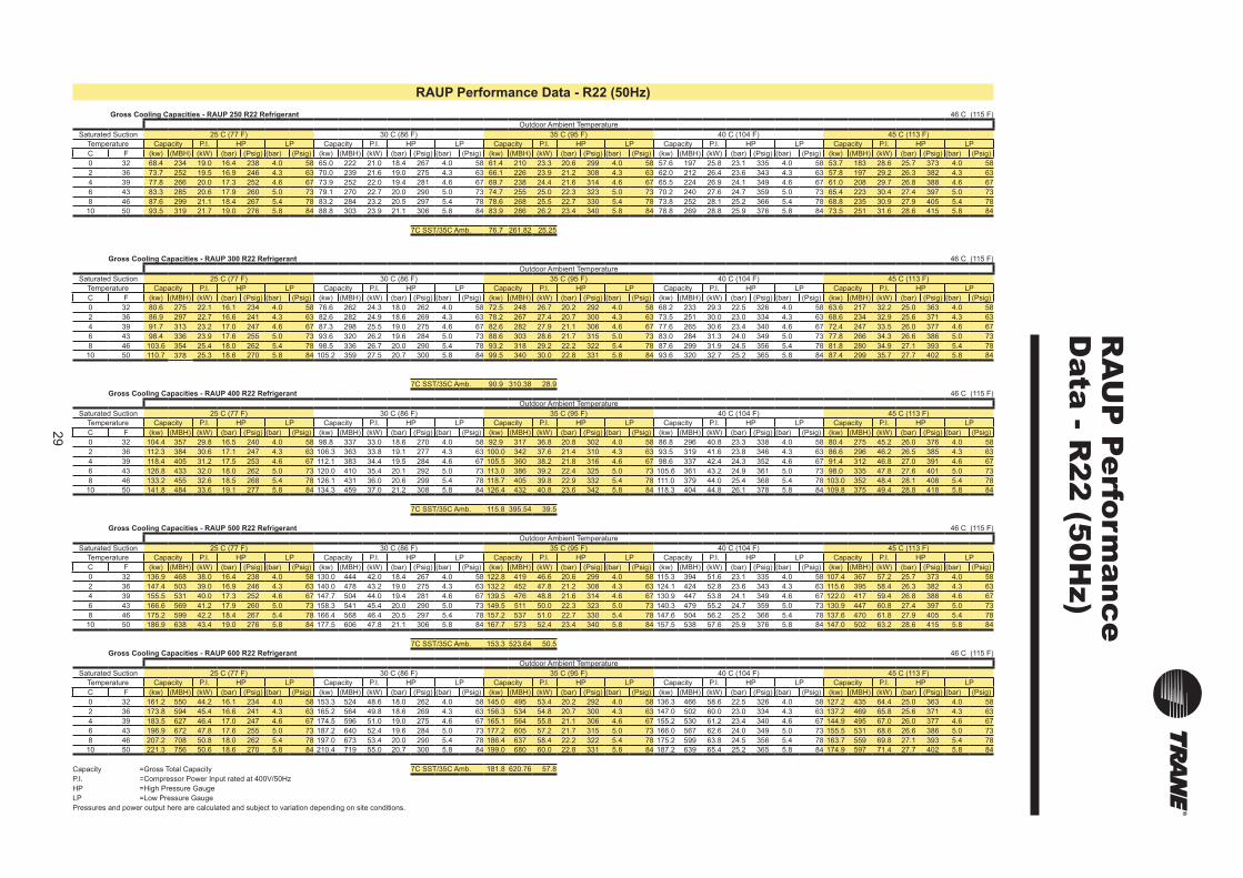
RAUP Performance Data - R22 (50Hz)
Gross Cooling Capacities - RAUP 250 R22 Refrigerant 46 C (115 F)
Outdoor Ambient Temperature
Saturated Suction 25 C (77 F) 30 C (86 F) 35 C (95 F) 40 C (104 F) 45 C (113 F)
Temperature Capacity P.I. HP LP Capacity P.I. HP LP Capacity P.I. HP LP Capacity P.I. HP LP Capacity P.I. HP LP
C F (kw) (MBH) (kW) (bar) (Psig) (bar) (Psig) (kw) (MBH) (kW) (bar) (Psig) (bar) (Psig) (kw) (MBH) (kW) (bar) (Psig) (bar) (Psig) (kw) (MBH) (kW) (bar) (Psig) (bar) (Psig) (kw) (MBH) (kW) (bar) (Psig) (bar) (Psig)
0 32 68.4 234 19.0 16.4 238 4.0 58 65.0 222 21.0 18.4 267 4.0 58 61.4 210 23.3 20.6 299 4.0 58 57.6 197 25.8 23.1 335 4.0 58 53.7 183 28.6 25.7 373 4.0 58
2 36 73.7 252 19.5 16.9 246 4.3 63 70.0 239 21.6 19.0 275 4.3 63 66.1 226 23.9 21.2 308 4.3 63 62.0 212 26.4 23.6 343 4.3 63 57.8 197 29.2 26.3 382 4.3 63
4 39 77.8 266 20.0 17.3 252 4.6 67 73.9 252 22.0 19.4 281 4.6 67 69.7 238 24.4 21.6 314 4.6 67 65.5 224 26.9 24.1 349 4.6 67 61.0 208 29.7 26.8 388 4.6 67
6 43 83.3 285 20.6 17.9 260 5.0 73 79.1 270 22.7 20.0 290 5.0 73 74.7 255 25.0 22.3 323 5.0 73 70.2 240 27.6 24.7 359 5.0 73 65.4 223 30.4 27.4 397 5.0 73
8 46 87.6 299 21.1 18.4 267 5.4 78 83.2 284 23.2 20.5 297 5.4 78 78.6 268 25.5 22.7 330 5.4 78 73.8 252 28.1 25.2 366 5.4 78 68.8 235 30.9 27.9 405 5.4 78
10 50 93.5 319 21.7 19.0 276 5.8 84 88.8 303 23.9 21.1 306 5.8 84 83.9 286 26.2 23.4 340 5.8 84 78.8 269 28.8 25.9 376 5.8 84 73.5 251 31.6 28.6 415 5.8 84
7C SST/35C Amb. 76.7 261.82 25.25
Gross Cooling Capacities - RAUP 300 R22 Refrigerant 46 C (115 F)
Outdoor Ambient Temperature
Saturated Suction 25 C (77 F) 30 C (86 F) 35 C (95 F) 40 C (104 F) 45 C (113 F)
Temperature Capacity P.I. HP LP Capacity P.I. HP LP Capacity P.I. HP LP Capacity P.I. HP LP Capacity P.I. HP LP
C F (kw) (MBH) (kW) (bar) (Psig) (bar) (Psig) (kw) (MBH) (kW) (bar) (Psig) (bar) (Psig) (kw) (MBH) (kW) (bar) (Psig) (bar) (Psig) (kw) (MBH) (kW) (bar) (Psig) (bar) (Psig) (kw) (MBH) (kW) (bar) (Psig) (bar) (Psig)
0 32 80.6 275 22.1 16.1 234 4.0 58 76.6 262 24.3 18.0 262 4.0 58 72.5 248 26.7 20.2 292 4.0 58 68.2 233 29.3 22.5 326 4.0 58 63.6 217 32.2 25.0 363 4.0 58
2 36 86.9 297 22.7 16.6 241 4.3 63 82.6 282 24.9 18.6 269 4.3 63 78.2 267 27.4 20.7 300 4.3 63 73.5 251 30.0 23.0 334 4.3 63 68.6 234 32.9 25.6 371 4.3 63
4 39 91.7 313 23.2 17.0 247 4.6 67 87.3 298 25.5 19.0 275 4.6 67 82.6 282 27.9 21.1 306 4.6 67 77.6 265 30.6 23.4 340 4.6 67 72.4 247 33.5 26.0 377 4.6 67
6 43 98.4 336 23.9 17.6 255 5.0 73 93.6 320 26.2 19.6 284 5.0 73 88.6 303 28.6 21.7 315 5.0 73 83.0 284 31.3 24.0 349 5.0 73 77.8 266 34.3 26.6 386 5.0 73
8 46 103.6 354 25.4 18.0 262 5.4 78 98.5 336 26.7 20.0 290 5.4 78 93.2 318 29.2 22.2 322 5.4 78 87.6 299 31.9 24.5 356 5.4 78 81.8 280 34.9 27.1 393 5.4 78
10 50 110.7 378 25.3 18.6 270 5.8 84 105.2 359 27.5 20.7 300 5.8 84 99.5 340 30.0 22.8 331 5.8 84 93.6 320 32.7 25.2 365 5.8 84 87.4 299 35.7 27.7 402 5.8 84
7C SST/35C Amb. 90.9 310.38 28.9
Gross Cooling Capacities - RAUP 400 R22 Refrigerant 46 C (115 F)
Outdoor Ambient Temperature
Saturated Suction 25 C (77 F) 30 C (86 F) 35 C (95 F) 40 C (104 F) 45 C (113 F)
Temperature Capacity P.I. HP LP Capacity P.I. HP LP Capacity P.I. HP LP Capacity P.I. HP LP Capacity P.I. HP LP
C F (kw) (MBH) (kW) (bar) (Psig) (bar) (Psig) (kw) (MBH) (kW) (bar) (Psig) (bar) (Psig) (kw) (MBH) (kW) (bar) (Psig) (bar) (Psig) (kw) (MBH) (kW) (bar) (Psig) (bar) (Psig) (kw) (MBH) (kW) (bar) (Psig) (bar) (Psig)
0 32 104.4 357 29.8 16.5 240 4.0 58 98.8 337 33.0 18.6 270 4.0 58 92.9 317 36.8 20.8 302 4.0 58 86.8 296 40.8 23.3 338 4.0 58 80.4 275 45.2 26.0 376 4.0 58
2 36 112.3 384 30.6 17.1 247 4.3 63 106.3 363 33.8 19.1 277 4.3 63 100.0 342 37.6 21.4 310 4.3 63 93.5 319 41.6 23.8 346 4.3 63 86.6 296 46.2 26.5 385 4.3 63
4 39 118.4 405 31.2 17.5 253 4.6 67 112.1 383 34.4 19.5 284 4.6 67 105.5 360 38.2 21.8 316 4.6 67 98.6 337 42.4 24.3 352 4.6 67 91.4 312 46.8 27.0 391 4.6 67
6 43 126.8 433 32.0 18.0 262 5.0 73 120.0 410 35.4 20.1 292 5.0 73 113.0 386 39.2 22.4 325 5.0 73 105.6 361 43.2 24.9 361 5.0 73 98.0 335 47.8 27.6 401 5.0 73
8 46 133.2 455 32.6 18.5 268 5.4 78 126.1 431 36.0 20.6 299 5.4 78 118.7 405 39.8 22.9 332 5.4 78 111.0 379 44.0 25.4 368 5.4 78 103.0 352 48.4 28.1 408 5.4 78
10 50 141.8 484 33.6 19.1 277 5.8 84 134.3 459 37.0 21.2 308 5.8 84 126.4 432 40.8 23.6 342 5.8 84 118.3 404 44.8 26.1 378 5.8 84 109.8 375 49.4 28.8 418 5.8 84
7C SST/35C Amb. 115.8 395.54 39.5
Gross Cooling Capacities - RAUP 500 R22 Refrigerant 46 C (115 F)
Outdoor Ambient Temperature
Saturated Suction 25 C (77 F) 30 C (86 F) 35 C (95 F) 40 C (104 F) 45 C (113 F)
Temperature Capacity P.I. HP LP Capacity P.I. HP LP Capacity P.I. HP LP Capacity P.I. HP LP Capacity P.I. HP LP
C F (kw) (MBH) (kW) (bar) (Psig) (bar) (Psig) (kw) (MBH) (kW) (bar) (Psig) (bar) (Psig) (kw) (MBH) (kW) (bar) (Psig) (bar) (Psig) (kw) (MBH) (kW) (bar) (Psig) (bar) (Psig) (kw) (MBH) (kW) (bar) (Psig) (bar) (Psig)
0 32 136.9 468 38.0 16.4 238 4.0 58 130.0 444 42.0 18.4 267 4.0 58 122.8 419 46.6 20.6 299 4.0 58 115.3 394 51.6 23.1 335 4.0 58 107.4 367 57.2 25.7 373 4.0 58
2 36 147.4 503 39.0 16.9 246 4.3 63 140.0 478 43.2 19.0 275 4.3 63 132.2 452 47.8 21.2 308 4.3 63 124.1 424 52.8 23.6 343 4.3 63 115.6 395 58.4 26.3 382 4.3 63
4 39 155.5 531 40.0 17.3 252 4.6 67 147.7 504 44.0 19.4 281 4.6 67 139.5 476 48.8 21.6 314 4.6 67 130.9 447 53.8 24.1 349 4.6 67 122.0 417 59.4 26.8 388 4.6 67
6 43 166.6 569 41.2 17.9 260 5.0 73 158.3 541 45.4 20.0 290 5.0 73 149.5 511 50.0 22.3 323 5.0 73 140.3 479 55.2 24.7 359 5.0 73 130.9 447 60.8 27.4 397 5.0 73
8 46 175.2 599 42.2 18.4 267 5.4 78 166.4 568 46.4 20.5 297 5.4 78 157.2 537 51.0 22.7 330 5.4 78 147.6 504 56.2 25.2 366 5.4 78 137.6 470 61.8 27.9 405 5.4 78
10 50 186.9 638 43.4 19.0 276 5.8 84 177.5 606 47.8 21.1 306 5.8 84 167.7 573 52.4 23.4 340 5.8 84 157.5 538 57.6 25.9 376 5.8 84 147.0 502 63.2 28.6 415 5.8 84
7C SST/35C Amb. 153.3 523.64 50.5
Gross Cooling Capacities - RAUP 600 R22 Refrigerant 46 C (115 F)
Outdoor Ambient Temperature
Saturated Suction 25 C (77 F) 30 C (86 F) 35 C (95 F) 40 C (104 F) 45 C (113 F)
Temperature Capacity P.I. HP LP Capacity P.I. HP LP Capacity P.I. HP LP Capacity P.I. HP LP Capacity P.I. HP LP
C F (kw) (MBH) (kW) (bar) (Psig) (bar) (Psig) (kw) (MBH) (kW) (bar) (Psig) (bar) (Psig) (kw) (MBH) (kW) (bar) (Psig) (bar) (Psig) (kw) (MBH) (kW) (bar) (Psig) (bar) (Psig) (kw) (MBH) (kW) (bar) (Psig) (bar) (Psig)
0 32 161.2 550 44.2 16.1 234 4.0 58 153.3 524 48.6 18.0 262 4.0 58 145.0 495 53.4 20.2 292 4.0 58 136.3 466 58.6 22.5 326 4.0 58 127.2 435 64.4 25.0 363 4.0 58
2 36 173.8 594 45.4 16.6 241 4.3 63 165.2 564 49.8 18.6 269 4.3 63 156.3 534 54.8 20.7 300 4.3 63 147.0 502 60.0 23.0 334 4.3 63 137.2 469 65.8 25.6 371 4.3 63
4 39 183.5 627 46.4 17.0 247 4.6 67 174.5 596 51.0 19.0 275 4.6 67 165.1 564 55.8 21.1 306 4.6 67 155.2 530 61.2 23.4 340 4.6 67 144.9 495 67.0 26.0 377 4.6 67
6 43 196.9 672 47.8 17.6 255 5.0 73 187.2 640 52.4 19.6 284 5.0 73 177.2 605 57.2 21.7 315 5.0 73 166.0 567 62.6 24.0 349 5.0 73 155.5 531 68.6 26.6 386 5.0 73
8 46 207.2 708 50.8 18.0 262 5.4 78 197.0 673 53.4 20.0 290 5.4 78 186.4 637 58.4 22.2 322 5.4 78 175.2 599 63.8 24.5 356 5.4 78 163.7 559 69.8 27.1 393 5.4 78
10 50 221.3 756 50.6 18.6 270 5.8 84 210.4 719 55.0 20.7 300 5.8 84 199.0 680 60.0 22.8 331 5.8 84 187.2 639 65.4 25.2 365 5.8 84 174.9 597 71.4 27.7 402 5.8 84
Capacity =Gross Total Capacity 7C SST/35C Amb. 181.8 620.76 57.8
P.I. =Compressor Power Input rated at 400V/50Hz
HP =High Pressure Gauge
LP =Low Pressure Gauge
Pressures and power output here are calculated and subject to variation depending on site conditions.

30
RA
UP
Pe
rform
an
ce
Data
- R4
07
C (5
0H
z)
RAUP Performance Data - R407C (50Hz)
Gross Cooling Capacities - RAUP 250 R407C Refrigerant 46 C (115 F)
Outdoor Ambient Temperature
Saturated Suction 25 C (77 F) 30 C (86 F) 35 C (95 F) 40 C (104 F) 45 C (113 F)
Temperature Capacity P.I. HP LP Capacity P.I. HP LP Capacity P.I. HP LP Capacity P.I. HP LP Capacity P.I. HP LP
C F (kw) (MBH) (kW) (bar) (Psig) (bar) (Psig) (kw) (MBH) (kW) (bar) (Psig) (bar) (Psig) (kw) (MBH) (kW) (bar) (Psig) (bar) (Psig) (kw) (MBH) (kW) (bar) (Psig) (bar) (Psig) (kw) (MBH) (kW) (bar) (Psig) (bar) (Psig)
0 32 65.0 222 19.0 16.4 238 4.0 58 61.7 211 21.0 18.4 267 4.0 58 58.3 199 23.3 20.6 299 4.0 58 54.8 187 25.8 23.1 335 4.0 58 51.0 174 28.6 25.7 373 4.0 58
2 36 70.0 239 19.5 16.9 246 4.3 63 66.5 227 21.6 19.0 275 4.3 63 62.8 215 23.9 21.2 308 4.3 63 58.9 201 26.4 23.6 343 4.3 63 54.9 188 29.2 26.3 382 4.3 63
4 39 73.9 252 20.0 17.3 252 4.6 67 70.2 240 22.0 19.4 281 4.6 67 66.2 226 24.4 21.6 314 4.6 67 62.2 212 26.9 24.1 349 4.6 67 57.9 198 29.7 26.8 388 4.6 67
6 43 79.2 270 20.6 17.9 260 5.0 73 75.2 257 22.7 20.0 290 5.0 73 71.0 243 25.0 22.3 323 5.0 73 66.7 228 27.6 24.7 359 5.0 73 62.2 212 30.4 27.4 397 5.0 73
8 46 83.2 284 21.1 18.4 267 5.4 78 79.0 270 23.2 20.5 297 5.4 78 74.7 255 25.5 22.7 330 5.4 78 70.1 239 28.1 25.2 366 5.4 78 65.4 223 30.9 27.9 405 5.4 78
10 50 88.8 303 21.7 19.0 276 5.8 84 84.3 288 23.9 21.1 306 5.8 84 79.7 272 26.2 23.4 340 5.8 84 74.8 256 28.8 25.9 376 5.8 84 69.8 239 31.6 28.6 415 5.8 84
7C SST/35C Amb. 72.8 248.73 25.25
Gross Cooling Capacities - RAUP 300 R407C Refrigerant 46 C (115 F)
Outdoor Ambient Temperature
Saturated Suction 25 C (77 F) 30 C (86 F) 35 C (95 F) 40 C (104 F) 45 C (113 F)
Temperature Capacity P.I. HP LP Capacity P.I. HP LP Capacity P.I. HP LP Capacity P.I. HP LP Capacity P.I. HP LP
C F (kw) (MBH) (kW) (bar) (Psig) (bar) (Psig) (kw) (MBH) (kW) (bar) (Psig) (bar) (Psig) (kw) (MBH) (kW) (bar) (Psig) (bar) (Psig) (kw) (MBH) (kW) (bar) (Psig) (bar) (Psig) (kw) (MBH) (kW) (bar) (Psig) (bar) (Psig)
0 32 76.6 261 22.1 16.1 234 4.0 58 72.8 249 24.3 18.0 262 4.0 58 68.9 235 26.7 20.2 292 4.0 58 64.8 221 29.3 22.5 326 4.0 58 60.4 206 32.2 25.0 363 4.0 58
2 36 82.5 282 22.7 16.6 241 4.3 63 78.5 268 24.9 18.6 269 4.3 63 74.2 254 27.4 20.7 300 4.3 63 69.8 238 30.0 23.0 334 4.3 63 65.2 223 32.9 25.6 371 4.3 63
4 39 87.2 298 23.2 17.0 247 4.6 67 82.9 283 25.5 19.0 275 4.6 67 78.4 268 27.9 21.1 306 4.6 67 73.7 252 30.6 23.4 340 4.6 67 68.8 235 33.5 26.0 377 4.6 67
6 43 93.5 319 23.9 17.6 255 5.0 73 88.9 304 26.2 19.6 284 5.0 73 84.1 287 28.6 21.7 315 5.0 73 78.9 269 31.3 24.0 349 5.0 73 73.9 252 34.3 26.6 386 5.0 73
8 46 98.4 336 25.4 18.0 262 5.4 78 93.6 320 26.7 20.0 290 5.4 78 88.5 302 29.2 22.2 322 5.4 78 83.2 284 31.9 24.5 356 5.4 78 77.8 266 34.9 27.1 393 5.4 78
10 50 105.1 359 25.3 18.6 270 5.8 84 100.0 341 27.5 20.7 300 5.8 84 94.5 323 30.0 22.8 331 5.8 84 88.9 304 32.7 25.2 365 5.8 84 83.1 284 35.7 27.7 402 5.8 84
7C SST/35C Amb. 86.3 294.86 28.9
Gross Cooling Capacities - RAUP 400 R407C Refrigerant 46 C (115 F)
Outdoor Ambient Temperature
Saturated Suction 25 C (77 F) 30 C (86 F) 35 C (95 F) 40 C (104 F) 45 C (113 F)
Temperature Capacity P.I. HP LP Capacity P.I. HP LP Capacity P.I. HP LP Capacity P.I. HP LP Capacity P.I. HP LP
C F (kw) (MBH) (kW) (bar) (Psig) (bar) (Psig) (kw) (MBH) (kW) (bar) (Psig) (bar) (Psig) (kw) (MBH) (kW) (bar) (Psig) (bar) (Psig) (kw) (MBH) (kW) (bar) (Psig) (bar) (Psig) (kw) (MBH) (kW) (bar) (Psig) (bar) (Psig)
0 32 99.2 339 29.8 16.5 240 4.0 58 93.8 320 33.0 18.6 270 4.0 58 88.3 301 36.8 20.8 302 4.0 58 82.5 282 40.8 23.3 338 4.0 58 76.4 261 45.2 26.0 376 4.0 58
2 36 106.7 364 30.6 17.1 247 4.3 63 101.0 345 33.8 19.1 277 4.3 63 95.0 325 37.6 21.4 310 4.3 63 88.8 303 41.6 23.8 346 4.3 63 82.3 281 46.2 26.5 385 4.3 63
4 39 112.5 384 31.2 17.5 253 4.6 67 106.5 364 34.4 19.5 284 4.6 67 100.2 342 38.2 21.8 316 4.6 67 93.7 320 42.4 24.3 352 4.6 67 86.8 297 46.8 27.0 391 4.6 67
6 43 120.4 411 32.0 18.0 262 5.0 73 114.0 389 35.4 20.1 292 5.0 73 107.3 367 39.2 22.4 325 5.0 73 100.3 343 43.2 24.9 361 5.0 73 93.1 318 47.8 27.6 401 5.0 73
8 46 126.5 432 32.6 18.5 268 5.4 78 119.8 409 36.0 20.6 299 5.4 78 112.7 385 39.8 22.9 332 5.4 78 105.4 360 44.0 25.4 368 5.4 78 97.8 334 48.4 28.1 408 5.4 78
10 50 134.7 460 33.6 19.1 277 5.8 84 127.6 436 37.0 21.2 308 5.8 84 120.1 410 40.8 23.6 342 5.8 84 112.4 384 44.8 26.1 378 5.8 84 104.3 356 49.4 28.8 418 5.8 84
7C SST/35C Amb. 110.0 375.76 39.5
Gross Cooling Capacities - RAUP 500 R407C Refrigerant 46 C (115 F)
Outdoor Ambient Temperature
Saturated Suction 25 C (77 F) 30 C (86 F) 35 C (95 F) 40 C (104 F) 45 C (113 F)
Temperature Capacity P.I. HP LP Capacity P.I. HP LP Capacity P.I. HP LP Capacity P.I. HP LP Capacity P.I. HP LP
C F (kw) (MBH) (kW) (bar) (Psig) (bar) (Psig) (kw) (MBH) (kW) (bar) (Psig) (bar) (Psig) (kw) (MBH) (kW) (bar) (Psig) (bar) (Psig) (kw) (MBH) (kW) (bar) (Psig) (bar) (Psig) (kw) (MBH) (kW) (bar) (Psig) (bar) (Psig)
0 32 130.0 444 38.0 16.4 238 4.0 58 123.5 422 42.0 18.4 267 4.0 58 116.7 398 46.6 20.6 299 4.0 58 109.5 374 51.6 23.1 335 4.0 58 102.1 349 57.2 25.7 373 4.0 58
2 36 140.0 478 39.0 16.9 246 4.3 63 133.0 454 43.2 19.0 275 4.3 63 125.6 429 47.8 21.2 308 4.3 63 117.9 403 52.8 23.6 343 4.3 63 109.8 375 58.4 26.3 382 4.3 63
4 39 147.7 505 40.0 17.3 252 4.6 67 140.3 479 44.0 19.4 281 4.6 67 132.5 453 48.8 21.6 314 4.6 67 124.4 425 53.8 24.1 349 4.6 67 115.9 396 59.4 26.8 388 4.6 67
6 43 158.3 541 41.2 17.9 260 5.0 73 150.4 514 45.4 20.0 290 5.0 73 142.0 485 50.0 22.3 323 5.0 73 133.3 455 55.2 24.7 359 5.0 73 124.3 425 60.8 27.4 397 5.0 73
8 46 166.5 569 42.2 18.4 267 5.4 78 158.1 540 46.4 20.5 297 5.4 78 149.3 510 51.0 22.7 330 5.4 78 140.2 479 56.2 25.2 366 5.4 78 130.7 447 61.8 27.9 405 5.4 78
10 50 177.6 607 43.4 19.0 276 5.8 84 168.6 576 47.8 21.1 306 5.8 84 159.4 544 52.4 23.4 340 5.8 84 149.7 511 57.6 25.9 376 5.8 84 139.7 477 63.2 28.6 415 5.8 84
7C SST/35C Amb. 145.7 497.45 50.5
Gross Cooling Capacities - RAUP 600 R407C Refrigerant 46 C (115 F)
Outdoor Ambient Temperature
Saturated Suction 25 C (77 F) 30 C (86 F) 35 C (95 F) 40 C (104 F) 45 C (113 F)
Temperature Capacity P.I. HP LP Capacity P.I. HP LP Capacity P.I. HP LP Capacity P.I. HP LP Capacity P.I. HP LP
C F (kw) (MBH) (kW) (bar) (Psig) (bar) (Psig) (kw) (MBH) (kW) (bar) (Psig) (bar) (Psig) (kw) (MBH) (kW) (bar) (Psig) (bar) (Psig) (kw) (MBH) (kW) (bar) (Psig) (bar) (Psig) (kw) (MBH) (kW) (bar) (Psig) (bar) (Psig)
0 32 153.1 523 44.2 16.1 234 4.0 58 145.6 497 48.6 18.0 262 4.0 58 137.7 470 53.4 20.2 292 4.0 58 129.5 442 58.6 22.5 326 4.0 58 120.9 413 64.4 25.0 363 4.0 58
2 36 165.1 564 45.4 16.6 241 4.3 63 157.0 536 49.8 18.6 269 4.3 63 148.5 507 54.8 20.7 300 4.3 63 139.6 477 60.0 23.0 334 4.3 63 130.3 445 65.8 25.6 371 4.3 63
4 39 174.3 595 46.4 17.0 247 4.6 67 165.8 566 51.0 19.0 275 4.6 67 156.8 536 55.8 21.1 306 4.6 67 147.4 504 61.2 23.4 340 4.6 67 137.6 470 67.0 26.0 377 4.6 67
6 43 187.1 639 47.8 17.6 255 5.0 73 177.9 608 52.4 19.6 284 5.0 73 168.3 575 57.2 21.7 315 5.0 73 157.7 539 62.6 24.0 349 5.0 73 147.7 505 68.6 26.6 386 5.0 73
8 46 196.9 672 50.8 18.0 262 5.4 78 187.2 639 53.4 20.0 290 5.4 78 177.1 605 58.4 22.2 322 5.4 78 166.5 569 63.8 24.5 356 5.4 78 155.5 531 69.8 27.1 393 5.4 78
10 50 210.2 718 50.6 18.6 270 5.8 84 199.9 683 55.0 20.7 300 5.8 84 189.1 646 60.0 22.8 331 5.8 84 177.8 607 65.4 25.2 365 5.8 84 166.1 567 71.4 27.7 402 5.8 84
Capacity =Gross Total Capacity 7C SST/35C Amb. 172.7 589.72 57.8
P.I. =Compressor Power Input rated at 400V/50Hz
HP =High Pressure Gauge
LP =Low Pressure Gauge
Pressures and power output here are calculated and subject to variation depending on site conditions.

31
RA
UP
-TT
V S
yste
m
SYSTEM PERFORMANCE DATA R22 Outdoor Ambient F (C)
Outdoor Indoor Indoor Unit Evap. On Coil Temp. 75 (24) 86 (30) 95 (35) 104 (40)
Unit Unit CFM EDB EWB TC SCH PI TC SCH PI TC SCH PI TC SCH PI
CMS F C F C MBH kW MBH kW kW MBH kW MBH kW kW MBH kW MBH kW kW MBH kW MBH kW kW
75 24 61 16 276 81 218 64 17 264 77 212 62 19 252 74 206 60 21 239 70 200 59 24
RAUP 250 TTV 250 7760 77 25 64 18 290 85 209 61 17 278 81 206 60 19 260 76 195 57 21 251 74 193 57 24
3.7 80 27 67 19 304 89 207 61 17 292 86 204 60 19 278 81 197 58 21 262 77 191 56 24
86 30 71 22 - - - - - - - - - - - -
75 24 61 16 206 60 165 48 14 197 58 251 74 22 301 88 247 72 25 286 84 240 70 28
RAUP 300 TTV 300 9240 77 25 64 18 217 63 158 46 15 208 61 241 71 22 316 93 237 69 25 299 88 230 67 28
4.4 80 27 67 19 228 67 157 46 15 218 64 240 70 22 333 98 237 69 25 317 93 228 67 28
86 30 71 22 243 71 166 49 15 233 68 - - - - - - - -
75 24 61 16 419 123 335 98 26 399 117 327 96 30 380 111 315 92 34 359 105 309 90 38
RAUP 400 TTV 400 12120 77 25 64 18 444 130 324 95 26 423 124 313 92 30 401 117 305 89 34 379 111 295 87 38
5.7 80 27 67 19 462 135 319 93 26 442 129 314 92 30 421 123 303 89 34 398 117 294 86 38
86 30 71 22 - - - - - - - - - - - -
75 24 61 16 536 157 440 129 33 513 150 426 125 37 490 143 416 122 42 464 136 371 109 47
RAUP 500 TTV 500 15130 77 25 64 18 565 165 418 122 33 540 158 410 120 37 515 151 397 116 42 487 143 385 113 47
7.1 80 27 67 19 592 173 420 123 33 568 166 409 120 37 541 159 395 116 42 514 151 386 113 47
86 30 71 22 - - - - - - - - - - - -
75 24 61 16 645 189 542 159 40 621 182 528 155 45 594 174 517 151 50 564 165 502 147 56
RAUP 600 TTV 600 18080 77 25 64 18 682 200 518 152 40 656 192 512 150 45 627 184 496 145 50 595 174 482 141 56
8.5 80 27 67 19 714 209 514 150 40 686 201 508 149 45 658 193 493 144 50 623 182 480 141 56
86 30 71 22 - - - - - - - - - - - -
SYSTEM PERFORMANCE DATA R407C Outdoor Ambient F (C)
Outdoor Indoor Indoor Unit Evap. On Coil Temp. 75 (24) 86 (30) 95 (35) 104 (40)
Unit Unit CFM EDB EWB TC SCH PI TC SCH PI TC SCH PI TC SCH PI
CMS F C F C MBH kW MBH kW kW MBH kW MBH kW kW MBH kW MBH kW kW MBH kW MBH kW kW
75 24 61 16 262 77 207 61 17 251 74 201 59 19 239 70 196 57 21 227 66 190 56 24
RAUP 250 TTV 250 7760 77 25 64 18 276 81 199 58 17 264 77 195 57 19 247 72 185 54 21 238 70 184 54 24
3.7 80 27 67 19 289 85 197 58 17 277 81 194 57 19 264 77 187 55 21 249 73 182 53 24
86 30 71 22 - - - - - - - - - - - -
75 24 61 16 195 57 156 46 14 187 55 239 70 22 286 84 234 69 25 271 79 228 67 28
RAUP 300 TTV 300 9240 77 25 64 18 206 60 150 44 15 197 58 229 67 22 300 88 225 66 25 284 83 219 64 28
4.4 80 27 67 19 216 63 149 44 15 207 61 228 67 22 316 93 225 66 25 301 88 217 63 28
86 30 71 22 - - 15 - - - - - - - - -
75 24 61 16 398 117 319 93 26 379 111 311 91 30 361 106 299 88 34 341 100 294 86 38
RAUP 400 TTV 400 12120 77 25 64 18 421 123 308 90 26 402 118 298 87 30 381 112 290 85 34 360 105 281 82 38
5.7 80 27 67 19 439 129 303 89 26 420 123 298 87 30 400 117 288 84 34 378 111 280 82 38
86 30 71 22 - - - - - - - - - - - -
75 24 61 16 510 149 418 122 33 488 143 405 119 37 465 136 396 116 42 441 129 352 103 47
RAUP 500 TTV 500 15130 77 25 64 18 536 157 397 116 33 513 150 390 114 37 489 143 377 110 42 463 136 366 107 47
7.1 80 27 67 19 562 165 399 117 33 540 158 389 114 37 514 151 375 110 42 488 143 366 107 47
86 30 71 22 - - - - - - - - - - - -
75 24 61 16 613 179 515 151 40 590 173 502 147 45 564 165 491 144 50 536 157 477 140 56
RAUP 600 TTV 600 18080 77 25 64 18 648 190 493 144 40 624 183 486 142 45 596 175 471 138 50 565 165 458 134 56
8.5 80 27 67 19 678 199 488 143 40 652 191 482 141 45 625 183 468 137 50 592 173 456 133 56
86 30 71 22 - - - - - - - - - - - -
Notes
TC Gross Total Capacity All Capacities are gross and do not include a deduction for evaporator fan motor heat..
SC Sensible Capacity Interpolation is allowed. Do not extrapolate.
PI Power Imput, kW Compressors
Fo
r ea
se
of s
ele
ctio
n, 5
pre
se
lecte
d s
yste
ms w
ith in
do
or u
nits
TT
V a
re a
va
ilab
le a
s in
the
follo
win
g p
erfo
rma
nce
tab
le.
32
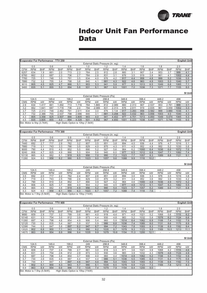
Indoor Unit Fan Performance Data
Evaporator For Performance - TTV 250 English Unit
External Static Pressure (in. wg)
0.5 0.6 0.8 1.0 1.2 1.4 1.6 1.8 2.0
CFM RPM BHP RPM BHP RPM BHP RPM BHP RPM BHP RPM BHP RPM BHP RPM BHP RPM BHP
6207 634 1.9 661 2.0 713 2.3 764 2.5 812 2.8 860 3.1 907 3.4 953 3.7 999 4.1
6760 662 2.2 687 2.3 736 2.7 784 2.8 831 3.1 876 3.5 919 3.8 961 4.1 1002 4.4
7760 725 3.1 748 3.3 791 3.5 834 4.0 876 4.2 917 4.4 958 4.8 999 5.2 1036 5.5
7880 732 3.2 755 3.4 798 3.6 840 4.1 881 4.3 922 4.6 963 4.9 1003 5.3 1040 5.7
9010 805 4.5 825 4.7 866 5.1 903 5.3 941 5.9 977 6.3 1013 6.5 1049 6.8 1065 7.1
9460 835 5.1 855 5.3 894 5.8 931 6.1 967 6.5 1001 7.0 1036 7.3 1071 7.7 1105 8.0
SI Unit
External Static Pressure (Pa)
124.5 149.4 199.2 249 298.8 348.6 398.4 448.2 498
CMS RPM kW RPM kW RPM kW RPM kW RPM kW RPM kW RPM kW RPM kW RPM kW
2.9 634 1.417 661 1.492 713 1.716 764 1.865 812 2.089 860 2.313 907 2.537 953 2.761 999 3.1
3.2 662 1.641 687 1.716 736 2.0 784 2.089 831 2.313 876 2.611 919 2.835 961 3.059 1002 3.3
3.7 725 2.313 748 2.462 791 2.611 834 3.0 876 3.134 917 3.283 958 3.582 999 3.880 1036 4.1
3.7 732 2.388 755 2.537 798 2.686 840 3.1 881 3.208 922 3.432 963 3.656 1003 4.0 1040 4.3
4.3 805 3.358 825 3.507 866 3.805 903 4.0 941 4.402 977 4.701 1013 4.850 1049 5.074 1065 5.3
4.5 835 3.805 855 4.0 894 4.328 931 4.552 967 4.850 1001 5.223 1036 5.447 1071 5.746 1105 6.0
Std. Motor is 5hp (3.7kW). High Static Option is 10hp (7.5kW)
Evaporator For Performance - TTV 300 English Unit
External Static Pressure (in. wg)
0.5 0.6 0.8 1.0 1.2 1.4 1.6 1.8 2.0
CFM RPM BHP RPM BHP RPM BHP RPM BHP RPM BHP RPM BHP RPM BHP RPM BHP RPM BHP
7440 692 2.7 717 2.9 762 3.2 807 3.5 851 3.8 894 4.0 936 4.4 976 4.7 1016 5.1
7880 719 3.1 743 3.3 786 3.5 829 4.0 870 4.3 911 4.5 952 4.8 992 5.2 1030 5.6
9000 790 4.4 810 4.5 852 5.0 890 5.2 927 5.6 964 6.2 1000 6.4 1036 6.6 1072 7.0
9240 806 4.7 825 4.9 866 5.3 904 5.6 940 6.0 977 6.5 1012 6.8 1047 7.1 1082 7.4
10130 865 6.0 882 6.1 919 6.5 956 7.0 990 7.3 1023 7.7 1057 8.3 1089 8.8 1121 9.1
11260 924 8.0 958 8.2 990 8.5 1023 9.0 1057 9.6 1088 9.9 1118 10.2 - - - -
SI Unit
External Static Pressure (Pa)
124.5 149.4 199.2 249 298.8 348.6 398.4 448.2 498
CMS RPM kW RPM kW RPM kW RPM kW RPM kW RPM kW RPM kW RPM kW RPM kW
3.5 692 2.0 717 2.2 762 2.4 807 2.6 851 2.8 894 3.0 936 3.3 976 3.5 1016 3.8
3.7 719 2.3 743 2.5 786 2.6 829 3.0 870 3.2 911 3.4 952 3.6 992 3.9 1030 4.2
4.2 790 3.3 810 3.4 852 3.7 890 3.9 927 4.2 964 4.6 1000 4.8 1036 4.9 1072 5.2
4.4 806 3.5 825 3.7 866 4.0 904 4.2 940 4.5 977 4.9 1012 5.1 1047 5.3 1082 5.5
4.8 865 4.5 882 4.6 919 4.9 956 5.2 990 5.4 1023 5.7 1057 6.2 1089 6.6 1121 6.8
5.3 924 6.0 958 6.1 990 6.3 1023 6.7 1057 7.2 1088 7.4 1118 7.6 - - - -
Std. Motor is 7.5hp (5.5kW). High Static Option is 15hp (11kW)
Evaporator For Performance - TTV 400 English Unit
External Static Pressure (in. wg)
0.5 0.6 0.8 1.0 1.2 1.4 1.6 1.8 2.0
CFM RPM BHP RPM BHP RPM BHP RPM BHP RPM BHP RPM BHP RPM BHP RPM BHP RPM BHP
9680 609 2.9 737 3.2 799 3.6 861 4.0 918 4.4 971 4.8 1021 5.2 1068 5.6 1115 6.2
10140 631 3.3 754 3.5 812 3.9 873 4.4 930 4.8 983 5.2 1032 5.8 1078 6.2 1124 6.6
11260 687 4.3 798 4.6 854 4.9 906 5.4 960 5.9 1014 6.4 1062 6.9 1108 7.4 1152 7.9
12120 730 5.2 835 5.4 887 5.9 937 5.9 986 6.8 1036 7.4 1085 8.0 1131 8.6 1175 8.9
12390 744 5.5 847 5.8 897 6.2 947 6.7 994 7.2 1043 7.8 1093 8.3 1139 8.9 1182 9.4
13520 802 6.8 900 7.1 943 7.6 990 8.2 1035 8.7 1078 9.3 1123 9.8 1169 10.5 1213 11.1
14670 863 8.6 954 8.9 996 9.4 1035 9.9 1079 10.6 1154 11.3 1200 12.1 - - - -
SI Unit
External Static Pressure (Pa)
124.5 149.4 199.2 249 298.8 348.6 398.4 448.2 498
CMS RPM kW RPM kW RPM kW RPM kW RPM kW RPM kW RPM kW RPM kW RPM kW
4.6 609 2.2 737 2.4 799 2.7 861 3.0 918 3.3 971 3.6 1021 3.9 1068 4.2 1115 4.6
4.8 631 2.5 754 2.6 812 2.9 873 3.3 930 3.6 983 3.9 1032 4.3 1078 4.6 1124 4.9
5.3 687 3.2 798 3.4 854 3.7 906 4.0 960 4.4 1014 4.8 1062 5.2 1108 5.5 1152 5.9
5.7 730 3.9 835 4.0 887 4.4 937 4.4 986 5.1 1036 5.5 1085 6.0 1131 6.4 1175 6.6
5.8 744 4.1 847 4.3 897 4.6 947 5.0 994 5.4 1043 5.8 1093 6.2 1139 6.6 1182 7.0
6.4 802 5.1 900 5.3 943 5.7 990 6.1 1035 6.5 1078 6.9 1123 7.3 1169 7.8 1213 8.3
6.9 863 6.4 954 6.6 996 7.0 1035 7.4 1079 7.9 1154 8.4 1200 9.0 - - - -
Std. Motor is 7.5hp (5.5kW). High Static Option is 15hp (11kW)
33
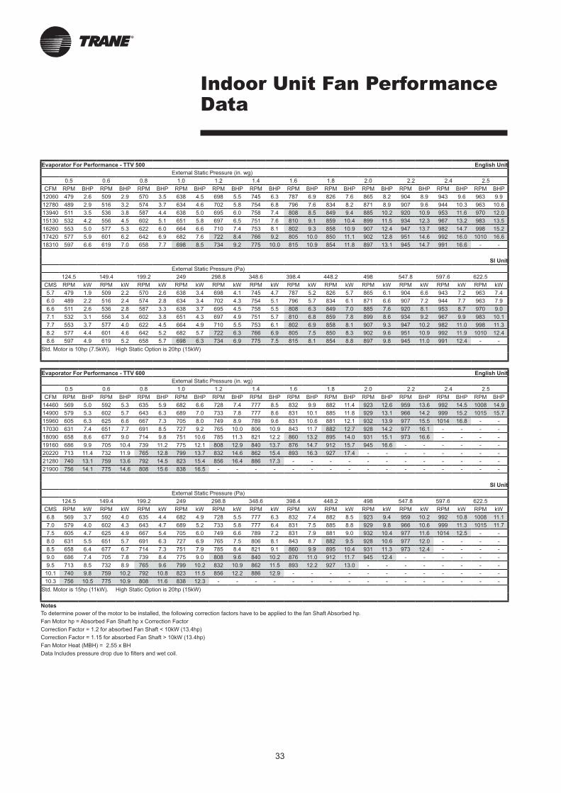
Indoor Unit Fan Performance Data
Evaporator For Performance - TTV 500 English Unit
External Static Pressure (in. wg)
0.5 0.6 0.8 1.0 1.2 1.4 1.6 1.8 2.0 2.2 2.4 2.5
CFM RPM BHP RPM BHP RPM BHP RPM BHP RPM BHP RPM BHP RPM BHP RPM BHP RPM BHP RPM BHP RPM BHP RPM BHP
12060 479 2.6 509 2.9 570 3.5 638 4.5 698 5.5 745 6.3 787 6.9 826 7.6 865 8.2 904 8.9 943 9.6 963 9.9
12780 489 2.9 516 3.2 574 3.7 634 4.6 702 5.8 754 6.8 796 7.6 834 8.2 871 8.9 907 9.6 944 10.3 963 10.6
13940 511 3.5 536 3.8 587 4.4 638 5.0 695 6.0 758 7.4 808 8.5 849 9.4 885 10.2 920 10.9 953 11.6 970 12.0
15130 532 4.2 556 4.5 602 5.1 651 5.8 697 6.5 751 7.6 810 9.1 859 10.4 899 11.5 934 12.3 967 13.2 983 13.5
16260 553 5.0 577 5.3 622 6.0 664 6.6 710 7.4 753 8.1 802 9.3 858 10.9 907 12.4 947 13.7 982 14.7 998 15.2
17420 577 5.9 601 6.2 642 6.9 682 7.6 722 8.4 766 9.2 805 10.0 850 11.1 902 12.8 951 14.6 992 16.0 1010 16.6
18310 597 6.6 619 7.0 658 7.7 698 8.5 734 9.2 775 10.0 815 10.9 854 11.8 897 13.1 945 14.7 991 16.6 - -
SI Unit
External Static Pressure (Pa)
124.5 149.4 199.2 249 298.8 348.6 398.4 448.2 498 547.8 597.6 622.5
CMS RPM kW RPM kW RPM kW RPM kW RPM kW RPM kW RPM kW RPM kW RPM kW RPM kW RPM kW RPM kW
5.7 479 1.9 509 2.2 570 2.6 638 3.4 698 4.1 745 4.7 787 5.2 826 5.7 865 6.1 904 6.6 943 7.2 963 7.4
6.0 489 2.2 516 2.4 574 2.8 634 3.4 702 4.3 754 5.1 796 5.7 834 6.1 871 6.6 907 7.2 944 7.7 963 7.9
6.6 511 2.6 536 2.8 587 3.3 638 3.7 695 4.5 758 5.5 808 6.3 849 7.0 885 7.6 920 8.1 953 8.7 970 9.0
7.1 532 3.1 556 3.4 602 3.8 651 4.3 697 4.9 751 5.7 810 6.8 859 7.8 899 8.6 934 9.2 967 9.9 983 10.1
7.7 553 3.7 577 4.0 622 4.5 664 4.9 710 5.5 753 6.1 802 6.9 858 8.1 907 9.3 947 10.2 982 11.0 998 11.3
8.2 577 4.4 601 4.6 642 5.2 682 5.7 722 6.3 766 6.9 805 7.5 850 8.3 902 9.6 951 10.9 992 11.9 1010 12.4
8.6 597 4.9 619 5.2 658 5.7 698 6.3 734 6.9 775 7.5 815 8.1 854 8.8 897 9.8 945 11.0 991 12.4 - -
Std. Motor is 10hp (7.5kW). High Static Option is 20hp (15kW)
Evaporator For Performance - TTV 600 English Unit
External Static Pressure (in. wg)
0.5 0.6 0.8 1.0 1.2 1.4 1.6 1.8 2.0 2.2 2.4 2.5
CFM RPM BHP RPM BHP RPM BHP RPM BHP RPM BHP RPM BHP RPM BHP RPM BHP RPM BHP RPM BHP RPM BHP RPM BHP
14460 569 5.0 592 5.3 635 5.9 682 6.6 728 7.4 777 8.5 832 9.9 882 11.4 923 12.6 959 13.6 992 14.5 1008 14.9
14900 579 5.3 602 5.7 643 6.3 689 7.0 733 7.8 777 8.6 831 10.1 885 11.8 929 13.1 966 14.2 999 15.2 1015 15.7
15960 605 6.3 625 6.6 667 7.3 705 8.0 749 8.9 789 9.6 831 10.6 881 12.1 932 13.9 977 15.5 1014 16.8 - -
17030 631 7.4 651 7.7 691 8.5 727 9.2 765 10.0 806 10.9 843 11.7 882 12.7 928 14.2 977 16.1 - - - -
18090 658 8.6 677 9.0 714 9.8 751 10.6 785 11.3 821 12.2 860 13.2 895 14.0 931 15.1 973 16.6 - - - -
19160 686 9.9 705 10.4 739 11.2 775 12.1 808 12.9 840 13.7 876 14.7 912 15.7 945 16.6 - - - - - -
20220 713 11.4 732 11.9 765 12.8 799 13.7 832 14.6 862 15.4 893 16.3 927 17.4 - - - - - - - -
21280 740 13.1 759 13.6 792 14.5 823 15.4 856 16.4 886 17.3 - - - - - - - - - - - -
21900 756 14.1 775 14.6 808 15.6 838 16.5 - - - - - - - - - - - - - - - -
SI Unit
External Static Pressure (Pa)
124.5 149.4 199.2 249 298.8 348.6 398.4 448.2 498 547.8 597.6 622.5
CMS RPM kW RPM kW RPM kW RPM kW RPM kW RPM kW RPM kW RPM kW RPM kW RPM kW RPM kW RPM kW
6.8 569 3.7 592 4.0 635 4.4 682 4.9 728 5.5 777 6.3 832 7.4 882 8.5 923 9.4 959 10.2 992 10.8 1008 11.1
7.0 579 4.0 602 4.3 643 4.7 689 5.2 733 5.8 777 6.4 831 7.5 885 8.8 929 9.8 966 10.6 999 11.3 1015 11.7
7.5 605 4.7 625 4.9 667 5.4 705 6.0 749 6.6 789 7.2 831 7.9 881 9.0 932 10.4 977 11.6 1014 12.5 - -
8.0 631 5.5 651 5.7 691 6.3 727 6.9 765 7.5 806 8.1 843 8.7 882 9.5 928 10.6 977 12.0 - - - -
8.5 658 6.4 677 6.7 714 7.3 751 7.9 785 8.4 821 9.1 860 9.9 895 10.4 931 11.3 973 12.4 - - - -
9.0 686 7.4 705 7.8 739 8.4 775 9.0 808 9.6 840 10.2 876 11.0 912 11.7 945 12.4 - - - - - -
9.5 713 8.5 732 8.9 765 9.6 799 10.2 832 10.9 862 11.5 893 12.2 927 13.0 - - - - - - - -
10.1 740 9.8 759 10.2 792 10.8 823 11.5 856 12.2 886 12.9 - - - - - - - - - - - -
10.3 756 10.5 775 10.9 808 11.6 838 12.3 - - - - - - - - - - - - - - - -
Std. Motor is 15hp (11kW). High Static Option is 20hp (15kW)
Notes
To determine power of the motor to be installed, the following correction factors have to be applied to the fan Shaft Absorbed hp.
Fan Motor hp = Absorbed Fan Shaft hp x Correction Factor
Correction Factor = 1.2 for absorbed Fan Shaft < 10kW (13.4hp)
Correction Factor = 1.15 for absorbed Fan Shaft > 10kW (13.4hp)
Fan Motor Heat (MBH) = 2.55 x BH
Data Includes pressure drop due to filters and wet coil.
34
Line Sizing, Routing, and Component Selection
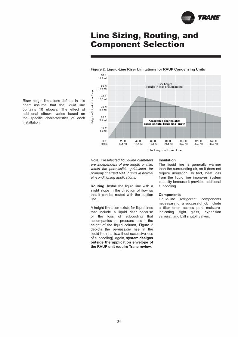
Note: Preselected liquid-line diameters
are independent of line length or rise,
within the permissible guidelines, for
properly charged RAUP units in normal
air-conditioning applications.
Routing. Install the liquid line with a
slight slope in the direction of flow so
that it can be routed with the suction
line.
A height limitation exists for liquid lines
that include a liquid riser because
of the loss of subcooling that
accompanies the pressure loss in the
height of the liquid column, Figure 2
depicts the permissible rise in the
liquid line (that is,without excessive loss
of subcooling). Again, system designs
outside the application envelope of
the RAUP unit require Trane review.
Riser height limitations defined in this
chart assume that the liquid line
contains 10 elbows. The effect of
additional elbows varies based on
the specific characteristics of each
installation.
Insulation
The liquid line is generally warmer
than the surrounding air, so it does not
require insulation. In fact, heat loss
from the liquid line improves system
capacity because it provides additional
subcooling.
Components
Liquid-line refrigerant components
necessary for a successful job include
a filter drier, access port, moisture-
indicating sight glass, expansion
valve(s), and ball shutoff valves.
Figure 2. Liquid-Line Riser Limitations for RAUP Condensing Units
35
Line Sizing, Routing, and Component Selection
These Components need to be
installed as close to the evaporator
as possible.
■ Filter drier. There is no substitute
for cleanliness during system
installation. The filter drier prevents
residual contaminants, introduced
during installation, from entering
the expansion valve and solenoid
valve.
■ Access port. The access port
allows the unit to be charged with
liquid refrigerant and is used to
determine subcooling. This port is
usually a Schraeder valve with a
core.
■ Moisture-indicating sight glass.
Be sure to install one
moisture-indicating sight glass in
the main liquid line. The sole value
of the sight glass is its moisture
indication ability. Use actual
measurements of temperature and
pressure — not the sight glass — to
determine subcooling and whether
the system is properly charged.
■ Expansion valve. The expansion
valve is the throttling device that
meters the refrigerant into the
evaporator coil. Metering too much
refrigerant floods the compressor;
metering too little elevates the
compressor temperature. Choosing
the correct size and type of
expansion valve is critical to assure
that it will correctly meter refrigerant
into the evaporator coil throughout
the entire operating envelope of
the system. Correct refrigerant
distribution into the coil requires
an expansion valve for each
distributor.
For improved modulation, choose
expansion valves with balanced
port construction and external
equalization.
■ Ball shutoff valves. Adding manual,
ball-type shutoff valves upstream
and downstream of the filter simplifies
replacement of the filter core.

36
Line Sizing, Routing, and Component Selection
Suction Lines
Line sizing. Proper suction-line sizing
is required to guarantee that the oil
returns to the compressor throughout
the system’s operating envelope. At the
same time, the line must be sized so
that the pressure drop does not
excessively affect capacity or efficiency.
To accomplish both objectives, it may
be necessary to use two different line
diameters: one for the horizontal run
and for vertical drops, and another for
the vertical lifts.
Routing. To prevent residual or
condensed refrigerant from “free-
flowing” toward the compressor, install
the suction line so that it slopes slightly
— that is, by ¼ inch to 1 inch per 10
feet of run [1 cm per 3 m] — toward the
evaporator.
When the application includes a
suction riser, oil must be forced to travel
the height of the riser. Riser traps and
double risers are unnecessary in the
suction line. All RAUP units unload
such that a single line size, standard
preselected, provides sufficient lift to
push entrained oil up the permissible
riser height. To assure proper oil
movement, the permissible unit
separationis 150 ft [45.7 m], including
a maximum vertical rise of 50 ft
[15 m]. System designs outside this
application envelope require Trane
review.
Total length of the suction line,
including a maximum rise of 50 feet,
must not exceed 150 feet.
Note: If a suction riser is properly
sized, oil will return to the compressor
regardless of whether a trap is present.
If a suction riser is oversized, adding
a trap will not restore proper oil
movement.
Avoid putting refrigerant lines
underground. Refrigerant condensation
or installation debris inside the line,
service access, and abrasion/corrosion
can quickly impair reliability.
Insulation. Any heat that transfers
from the surrounding air to the cooler
suction lines increases the load on the
condenser (reducing the system’s air-
conditioning capacity) and promotes
condensate formation (adversely
affecting indoor air quality). After
operating the system and testing all
fittings and joints to verify that the
system is leak-free, insulate the suction
lines to prevent heat gain and unwanted
condensation.
■ Access port. The access port is
used to determine suction pressure.
This port is usually a Schraeder
valve with a core.
Note: SVL (Solenoid valves) are only applicable to condensing units with relevant controls. The RAUP does not support SVL control.
Note: SVL (Solenoid valves) are only applicable to condensing units with relevant controls. The RAUP does not support SVL

Note: SVL (Solenoid valves) are only applicable to condensing units with relevant controls. The RAUP does not support SVL
Note: SVL (Solenoid valves) are only applicable to condensing units with relevant controls. The RAUP does not support SVL
Note: SVL (Solenoid valves) are only applicable to condensing units with relevant controls. The RAUP does not support SVL
46
Mechanical Specifications
Mechanical Specifications
Air Cooled Condensing Unit
Indoor Unit Air Handler
● The contractor shall furnish and install a split air cooled condensing unit of size and capacity scheduled at the required working condition.
● The unit shall operate with either a R22 or R407C refrigerant.
● The unit shall be fully wired with starters and controller at the factory.
● All units shall be furnished with hermetic scroll compressors, air cooled condenser and microprocessor control panel.
● Unit shall be able to operate down to 15 C as standard and lower with a low ambeint control option..
● Unit shall be able to operate up to 43 C as standard and up to 53 ºC with a high ambient option.
● The airflow through the condenser shall be handled by multiple direct drive fans. Each fan shall be statically and dynamically balanced. Fan motors shall be with permanently lubricated ball bearings, protected by thermal overloads.
● Units shall be designed and manufactured in accordance with the quality insurance ISO 9001.
Unit Construction
● The unit shall be designed for outdoor application and rust protected with polyester powder paint.
● The unit base, shall be manufactured with GI steel.● Unit panels shall be removable to facilitate easy service
with Allen Key locks.
● Compressor, air intake sections shall be protected with intake grilles as standard.
● Each unit shall be modular in design to facilate a modular installation to minimize installed space.
Condenser Coils
● Air cooled condenser coils shall be smooth bore with 3/8”copper tubes mechanically bonded to configured alluminium W3BS slit fins as standard.
● Coils shall be factory leak tested up to 450psig.● Higher corrosion resistant fins shall be available as an
option.
Refrigerant Circuit
● All units shall have 1 or 2 refrigeration circuits with a minimum of 2 manifolded compressors on each circuit for staging control.
● The manifolding piping shall be designed to ensure relable oil return management.
● Each circuit shall be provided with factory set high and low pressure switches.
Electrical
● Electrical panels shall be fully mounted and wired in the factory with full opening access panel.
● The starting mechanism of the fans and compressors shall be provide by the factory.
● A DOL starting mechanism shall be provided and installedby the factory.
Control System
● Units shall be completely factory wired with microprocessor based controls, starters and terminal block for power wiring.
● Control wiring shall be 230V.● Compressor overheat , overcurrent and phase loss
protection shall be provided.
● High and low pressure safety switches to protect the system against operations outside recommended pressure limits.
● Reverse rotation protection on compressors through safeties that trip the system on high temperature.
● Compressor time delays and on-off sequencing logic that is built into the microprocessor algorythm for maximum protection.
● A dry contact shall be available for remote signalling of general faults.
● Segment LED Display shall provide draguostios for troubleshooting and setpoint temperatures as well as actual size temperatures.
● A multi stage with zone sensors temperature control shall be standard factory installed.
Unit Casing
● The unit framework shall be constructed of GI steel. Exterior panels shall be fabricated from galvanized steel sheets, cleaned and coated with a baked polyester powder paint.
● All panels in contact with the air stream shall be insulated with closed cell PE insulation
● All panels shall be removable to ensure proper access for servicing and maintainence. Removable panels shall be secured with bolts.
Cooling Coil
● The evaporator coil shall be 1/2 or 3/8”OD seamless copper tubes, mechanically expanded into alluminium fins.
● Coils shall have at least 2 independent circuits for good part load capability (watched with RAUP 400-600).
● Coils shall be leak and proof tested up to 375psig. ● Expansion devices shall be thermal expansion valves.
● Drain pans shall be fabricated of GI, insulated with PE and corossion resistant coated with a corossion resistant coating.
Fans
● Supply fans shall be double width double inlet forward curve centrifugal fans, statically and dynamically balanced.
● The drive components shall be fixed pitch drives with multiple V belts. The supply fan motor shall be of a TEFC type, with built in thermal overloads.
● DOL Fan motor starters shall be provided as standard.
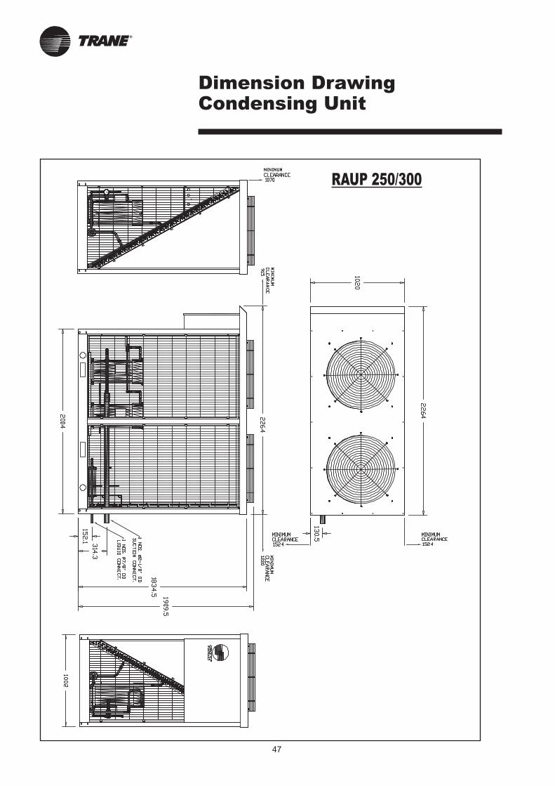
47
Dimension Drawing Condensing Unit
RAUP 250/300
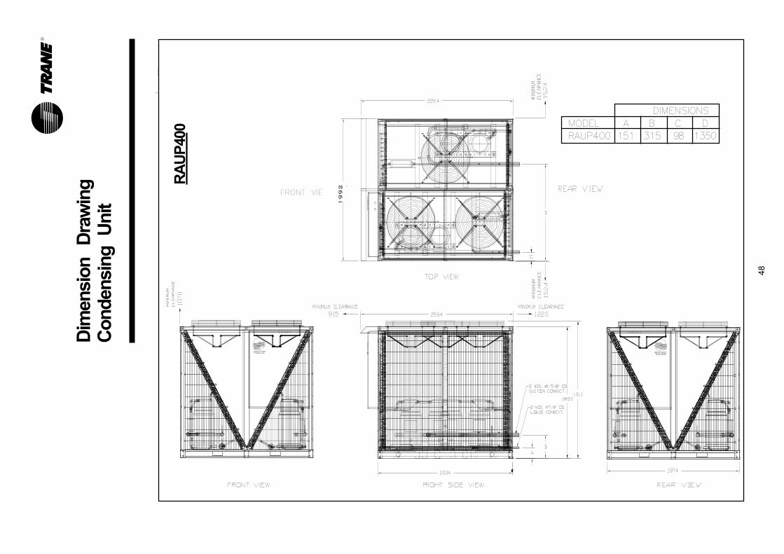
Dim
ensio
n
Dra
win
gC
ondensin
g U
nit
DIMENSIONSMODEL A B C DRAUP400 151 315 98 1350
1992
FRONT VIE
RA
UP
400
48
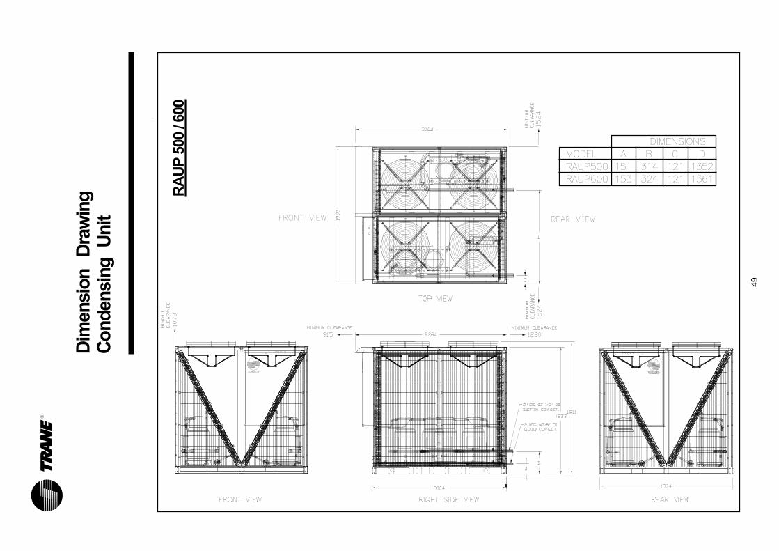
Dim
ensio
n
Dra
win
gC
ondensin
g U
nit
DIMENSIONSMODEL A B C DRAUP500 151 314 121 1352RAUP600 153 324 121 1361
FRONT VIEW
RA
UP
500 /
600
49
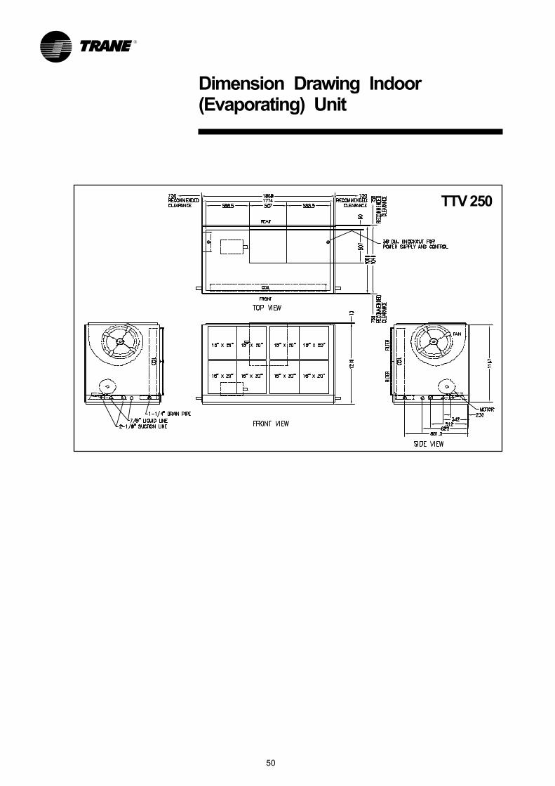
Dimension Drawing Indoor(Evaporating) Unit
50
TTV 250
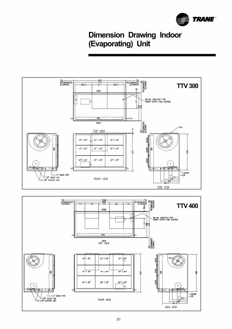
Dimension Drawing Indoor(Evaporating) Unit
51
TTV 300
TTV 400
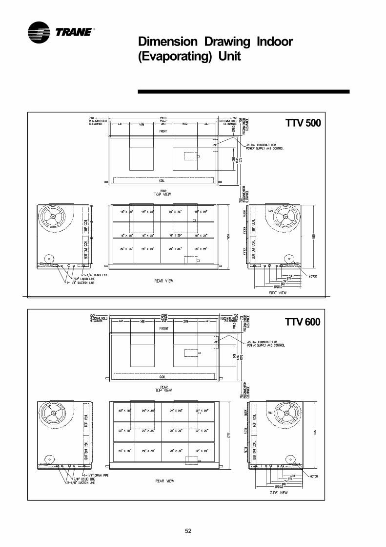
Dimension Drawing Indoor(Evaporating) Unit
TTV 500
TTV 600
52

53
Standard Conversion Table
To Convert From: To Multiply By:
Length
Feet (ft) meters (m) .30481
Inches (In) millimeters (mm) 25.4
Area
Square Feet (ft2) square meters (m2) .093
Square Inches (ln2) square millimeters (mm2) 645.2
Cubic Feet (ft3) Cubic Meters (m3) .0283
Cubic Inches (In3) Cubic mm (mm3) 16387
Gallons (gal) litres (l) 3.785
Gallons (gal) Cubic meters (m3) .003785
Flow
Cubic feet/min (cfm) cubic meters/second (m3/s) .000472
Cubic feet/min (cfm) cubic meters/hr (m3/hr) 1.69884
Gallons/minute (GPM) cubic meters/hr (m3/hr) .2271
Gallons/minute (GPM) litres/second (l/s) .06308
Velocity
Feet per minute (ft/m) meters per second (m/s) .00508
Feet per second (ft/s) meters per second (m/s) .3048
Energy and Power and Capacity
British Thermal Units (Btu/h) Kilowatt (kW) .000293
British Thermal Units (Btu/h) Kcalorie (Kcal) .252
Tons (refrig. effect) Kilowatt (refrig. effect) 3.516
Tons (refrig. effect) Kilocalories-per hour (Kcal/hr) 3024
Horsepower Kilowatt (kW) .7457
Pressure
Feet of water (ftH2O) Pascals (PA) 2990
Inches of water (inH2O) Pascals (PA) 249
Pounds per square inch (PSI*) Pascals (PA) 6895
PSI* Bar or KG/CM2 0.06895
*PSIG
To determine superheat, use Dew (Vapor) Point values.
To determine subcooling, use Bubble (Liquid) Point values.
Note: 3-phase amps or KVA can be used in single-phase
formulas by multiplying average phase leg current
times 3 or 1.73. Example:
KW = Real Power; KVA = Apparent Power
KW = KVA x Power Factor =
Motor KW = Motor KVA =
Motor HP = =
Pump HP =
HP =
Temperature: =
Refrig. Tons = =
KVA =V x A x 1.73
1000
V x A x Power Factor1000
HP x .746;Efficiency
HP x .746Eff. x Power Factor
KVA x Power Factor x Eff..746
KW x Eff..746
GPM x Total Heat (Ft. Water)Pump Eff. x 3960
Torque (lb.-ft.) x RPM5250
Btu/h12000
GPM x t24
OC5
OF-329
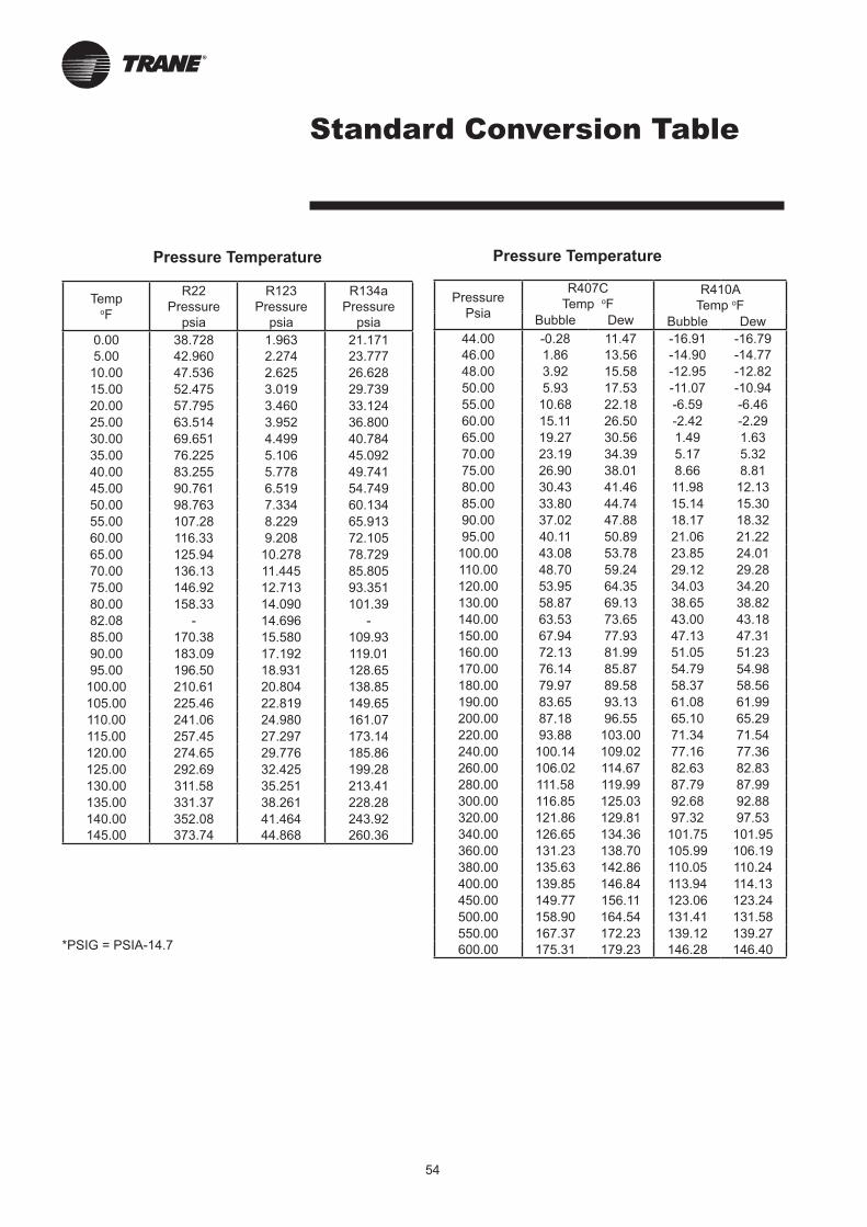
54
Standard Conversion Table
Pressure Temperature
TempoF
R22
Pressure
psia
R123
Pressure
psia
R134a
Pressure
psia
0.00 38.728 1.963 21.171
5.00 42.960 2.274 23.777
10.00 47.536 2.625 26.628
15.00 52.475 3.019 29.739
20.00 57.795 3.460 33.124
25.00 63.514 3.952 36.800
30.00 69.651 4.499 40.784
35.00 76.225 5.106 45.092
40.00 83.255 5.778 49.741
45.00 90.761 6.519 54.749
50.00 98.763 7.334 60.134
55.00 107.28 8.229 65.913
60.00 116.33 9.208 72.105
65.00 125.94 10.278 78.729
70.00 136.13 11.445 85.805
75.00 146.92 12.713 93.351
80.00 158.33 14.090 101.39
82.08 - 14.696 -
85.00 170.38 15.580 109.93
90.00 183.09 17.192 119.01
95.00 196.50 18.931 128.65
100.00 210.61 20.804 138.85
105.00 225.46 22.819 149.65
110.00 241.06 24.980 161.07
115.00 257.45 27.297 173.14
120.00 274.65 29.776 185.86
125.00 292.69 32.425 199.28
130.00 311.58 35.251 213.41
135.00 331.37 38.261 228.28
140.00 352.08 41.464 243.92
145.00 373.74 44.868 260.36
Pressure Temperature
Pressure
Psia
R407C
Temp oFR410A
Temp oFBubble Dew Bubble Dew
44.00 -0.28 11.47 -16.91 -16.79
46.00 1.86 13.56 -14.90 -14.77
48.00 3.92 15.58 -12.95 -12.82
50.00 5.93 17.53 -11.07 -10.94
55.00 10.68 22.18 -6.59 -6.46
60.00 15.11 26.50 -2.42 -2.29
65.00 19.27 30.56 1.49 1.63
70.00 23.19 34.39 5.17 5.32
75.00 26.90 38.01 8.66 8.81
80.00 30.43 41.46 11.98 12.13
85.00 33.80 44.74 15.14 15.30
90.00 37.02 47.88 18.17 18.32
95.00 40.11 50.89 21.06 21.22
100.00 43.08 53.78 23.85 24.01
110.00 48.70 59.24 29.12 29.28
120.00 53.95 64.35 34.03 34.20
130.00 58.87 69.13 38.65 38.82
140.00 63.53 73.65 43.00 43.18
150.00 67.94 77.93 47.13 47.31
160.00 72.13 81.99 51.05 51.23
170.00 76.14 85.87 54.79 54.98
180.00 79.97 89.58 58.37 58.56
190.00 83.65 93.13 61.08 61.99
200.00 87.18 96.55 65.10 65.29
220.00 93.88 103.00 71.34 71.54
240.00 100.14 109.02 77.16 77.36
260.00 106.02 114.67 82.63 82.83
280.00 111.58 119.99 87.79 87.99
300.00 116.85 125.03 92.68 92.88
320.00 121.86 129.81 97.32 97.53
340.00 126.65 134.36 101.75 101.95
360.00 131.23 138.70 105.99 106.19
380.00 135.63 142.86 110.05 110.24
400.00 139.85 146.84 113.94 114.13
450.00 149.77 156.11 123.06 123.24
500.00 158.90 164.54 131.41 131.58
550.00 167.37 172.23 139.12 139.27
600.00 175.31 179.23 146.28 146.40*PSIG = PSIA-14.7
Literature Order Number MUL-PRC004-E4 (August 2008)
File Number
Supersedes MUL-PRC004-E4 (August 2007)
Stocking Location Penang, Malaysia
TRANE has a policy of continuous product data and product improvement and reserves the right to
change design and specifications without notice.
Trane
For more information, contact your local district office