Embed Size (px)
Citation preview

ArcGIS®
9ArcGIS Survey Analyst Tutorial

Copyright © 2002–2006 ESRIAll rights reserved.Printed in the United States of America.
The information contained in this document is the exclusive property of ESRI. This work is protected under United States copyright law and otherinternational copyright treaties and conventions. No part of this work may be reproduced or transmitted in any form or by any means, electronic ormechanical, including photocopying and recording, or by any information storage or retrieval system, except as expressly permitted in writing by ESRI.All requests should be sent to Attention: Contracts Manager, ESRI, 380 New York Street, Redlands, CA 92373-8100, USA.
The information contained in this document is subject to change without notice.
CONTRIBUTING WRITERSTim Hodson and Kristin Clark
U.S. GOVERNMENT RESTRICTED/LIMITED RIGHTSAny software, documentation, and/or data delivered hereunder is subject to the terms of the License Agreement. In no event shall the U.S. Governmentacquire greater than RESTRICTED/LIMITED RIGHTS. At a minimum, use, duplication, or disclosure by the U.S. Government is subject to restrictionsas set forth in FAR §52.227-14 Alternates I, II, and III (JUN 1987); FAR §52.227-19 (JUN 1987) and/or FAR §12.211/12.212 (Commercial TechnicalData/Computer Software); and DFARS §252.227-7015 (NOV 1995) (Technical Data) and/or DFARS §227.7202 (Computer Software), as applicable.Contractor/Manufacturer is ESRI, 380 New York Street, Redlands, CA 92373-8100, USA.
ESRI, the ESRI globe logo, the ArcGIS logo, ArcView, ArcSDE, SDE, ArcEditor, ArcInfo, ArcCatalog, ArcMap, ArcGIS, GIS by ESRI, and www.esri.comare trademarks, registered trademarks, or service marks of ESRI in the United States, the European community, or certain other jurisdictions.
The names of other companies and products herein are trademarks or registered trademarks of their respective trademark owners.
attribution.pmd 05/18/2006, 3:30 PM1

IN THIS TUTORIAL
1
ArcGIS Survey Analyst Tutorial
• Exercise 1: Organizing the tutorialdata
• Exercise 2: Exploring the surveydataset
• Exercise 3: Working with surveydata
• Exercise 4: Creating COGOcomputations
• Exercise 5: Updating computa-tions and linked features
• Exercise 6: Exporting survey pointdata
ArcGIS® Survey Analyst has the tools you need to enter survey data andcoordinate geometry (COGO) into survey datasets. You can import the datayou’ve collected from a total station or enter the tape measurementsrecorded on a field sketch or a survey plan. Completing the exercises in thischapter will provide you with the basic knowledge to use these capabilities.
Tutorial scenario
Your organization is building a geodatabase for Maricopa County, Arizona.The geodatabase represents parcels and physical infrastructure. Your fieldcrew has performed a survey to relocate some parcel boundary monumentsand to fix the location of buildings for an existing subdivision. Coordinatedlocations of section corners in the area were used as control for the fieldsurvey. You will use a survey project in your geodatabase to importmeasurement data for the boundary monuments that were found, and forsome corners of buildings on the site of the survey. You will use thisinformation to update the geometry of an existing subdivision block in yourgeodatabase and add a new building based on tape measurements recordedin the field.
You will use a second project to add values recorded on the originalsubdivision plan. The survey points computed in this second project will beexported for use by the field crew to locate any monuments that were notfound in the first field survey. You will use georeferenced images of theoriginal subdivision survey plans as a background for your work.
Ch02.pmd 05/18/2006, 3:40 PM1
2 ARCGIS SURVEY ANALYST TUTORIAL
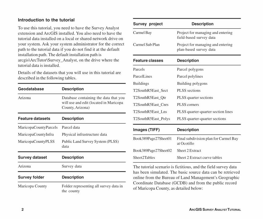
Introduction to the tutorial
To use this tutorial, you need to have the Survey Analystextension and ArcGIS installed. You also need to have thetutorial data installed on a local or shared network drive onyour system. Ask your system administrator for the correctpath to the tutorial data if you do not find it at the defaultinstallation path. The default installation path isarcgis\ArcTutor\Survey_Analyst, on the drive where thetutorial data is installed.
Details of the datasets that you will use in this tutorial aredescribed in the following tables.
Geodatabase Description
Arizona Database containing the data that youwill use and edit (located in MaricopaCounty, Arizona)
Feature datasets Description
MaricopaCountyParcels Parcel data
MaricopaCountyInfra Physical infrastructure data
MaricopaCountyPLSS Public Land Survey System (PLSS)data
Survey dataset Description
Arizona Survey data
Survey folder Description
Maricopa County Folder representing all survey data inthe county
Survey project Description
Carmel Bay Project for managing and enteringfield-based survey data
Carmel Sub Plan Project for managing and enteringplan-based survey data
Feature classes Description
Parcels Parcel polygons
ParcelLines Parcel polylines
Buildings Building polygons
T2SouthR5East_Sect PLSS sections
T2SouthR5East_Qtr PLSS quarter sections
T2SouthR5East_Cnrs PLSS corners
T2SouthR5East_Lns PLSS quarter-quarter section lines
T2SouthR5East_Polys PLSS quarter-quarter sections
Images (TIFF) Description
Book389Page27Sheet01 Final subdivision plan for Carmel Bayat Ocotillo
Book389Page27Sheet02 Sheet 2 Extract
Sheet2Tables Sheet 2 Extract curve tables
The tutorial scenario is fictitious, and the field survey datahas been simulated. The basic source data can be retrievedonline from the Bureau of Land Management’s GeographicCoordinate Database (GCDB) and from the public recordof Maricopa County, as detailed below:
Ch02.pmd 05/18/2006, 3:40 PM2
ARCGIS SURVEY ANALYST TUTORIAL 3
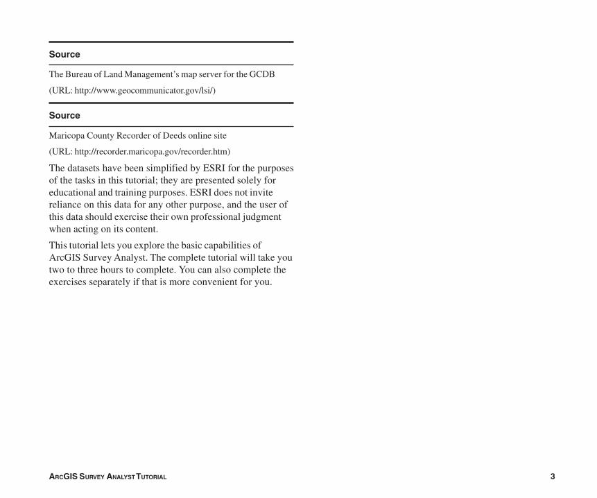
Source
The Bureau of Land Management’s map server for the GCDB
(URL: http://www.geocommunicator.gov/lsi/)
Source
Maricopa County Recorder of Deeds online site
(URL: http://recorder.maricopa.gov/recorder.htm)
The datasets have been simplified by ESRI for the purposesof the tasks in this tutorial; they are presented solely foreducational and training purposes. ESRI does not invitereliance on this data for any other purpose, and the user ofthis data should exercise their own professional judgmentwhen acting on its content.
This tutorial lets you explore the basic capabilities ofArcGIS Survey Analyst. The complete tutorial will take youtwo to three hours to complete. You can also complete theexercises separately if that is more convenient for you.
Ch02.pmd 05/18/2006, 3:40 PM3

4 ARCGIS SURVEY ANALYST TUTORIAL
Exercise 1: Organizing the tutorial data
Before you can begin this tutorial, you must first find andorganize the tutorial data that you will need. UsingArcCatalog, browse for and create a new folder connectionto your data:
1. Click the Start menu, point to Programs, point to ArcGIS,and click ArcCatalog.
2. Navigate to the location of the tutorial data (the defaultpath is \arcgis\ArcTutor on the drive where ArcGIS isinstalled).
3. Click the Survey_Analyst folder and drag it onto the top-level node of the Catalog tree.
Your new folder connection is now listed in the Catalogtree. Folder connections simplify the task of navigatingto your most frequently used datasets. You will now beable to access all the data needed for this tutorialthrough this new connection.
Enabling the Survey Analyst extension
Before continuing, you must enable Survey Analyst for usein ArcCatalog.
1. Click Tools and click Extensions.
2. Check the Survey Analyst check box.
3. Click Close.
32
1
Ch02.pmd 05/18/2006, 3:40 PM4
ARCGIS SURVEY ANALYST TUTORIAL 5
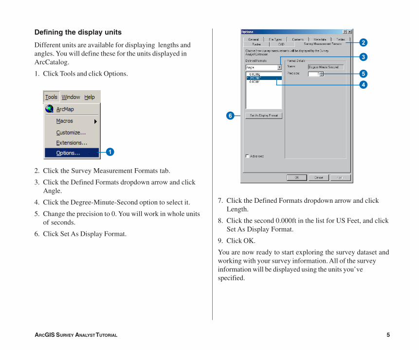
Defining the display units
Different units are available for displaying lengths andangles. You will define these for the units displayed inArcCatalog.
1. Click Tools and click Options.
2. Click the Survey Measurement Formats tab.
3. Click the Defined Formats dropdown arrow and clickAngle.
4. Click the Degree-Minute-Second option to select it.
5. Change the precision to 0. You will work in whole unitsof seconds.
6. Click Set As Display Format.
7. Click the Defined Formats dropdown arrow and clickLength.
8. Click the second 0.000ft in the list for US Feet, and clickSet As Display Format.
9. Click OK.
You are now ready to start exploring the survey dataset andworking with your survey information. All of the surveyinformation will be displayed using the units you’vespecified.
6
2
3
4
5
1
Ch02.pmd 05/18/2006, 3:40 PM5
6 ARCGIS SURVEY ANALYST TUTORIAL
Survey information is stored in the geodatabase in surveydatasets. A survey dataset is a comprehensive collection ofsurvey points, measurements, and computations. You definea single survey dataset to provide survey-awareness foreach logical group of feature datasets and feature classes.The survey dataset covers the extents of your managementarea.
Viewing the survey dataset properties
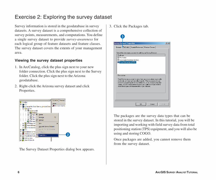
1. In ArcCatalog, click the plus sign next to your newfolder connection. Click the plus sign next to the Surveyfolder. Click the plus sign next to the Arizonageodatabase.
2. Right-click the Arizona survey dataset and clickProperties.
The Survey Dataset Properties dialog box appears.
Exercise 2: Exploring the survey dataset
3
2
3. Click the Packages tab.
The packages are the survey data types that can bestored in the survey dataset. In this tutorial, you will beimporting and working with field survey data from totalpositioning station (TPS) equipment, and you will also beusing and storing COGO.
Once packages are added, you cannot remove themfrom the survey dataset.
Ch02.pmd 05/18/2006, 3:40 PM6
ARCGIS SURVEY ANALYST TUTORIAL 7
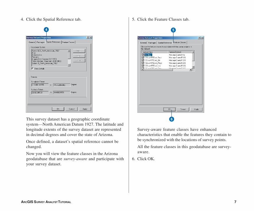
5. Click the Feature Classes tab.
Survey-aware feature classes have enhancedcharacteristics that enable the features they contain tobe synchronized with the locations of survey points.
All the feature classes in this geodatabase are survey-aware.
6. Click OK.
4. Click the Spatial Reference tab.
This survey dataset has a geographic coordinatesystem—North American Datum 1927. The latitude andlongitude extents of the survey dataset are representedin decimal degrees and cover the state of Arizona.
Once defined, a dataset’s spatial reference cannot bechanged.
Now you will view the feature classes in the Arizonageodatabase that are survey-aware and participate withyour survey dataset.
4 5
6
Ch02.pmd 05/18/2006, 3:40 PM7
8 ARCGIS SURVEY ANALYST TUTORIAL
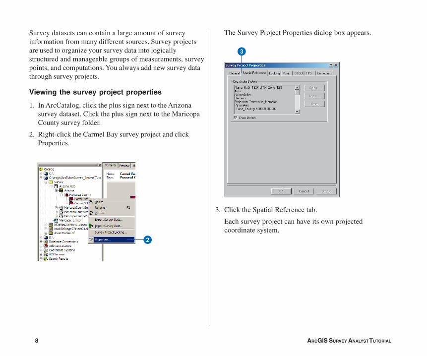
Survey datasets can contain a large amount of surveyinformation from many different sources. Survey projectsare used to organize your survey data into logicallystructured and manageable groups of measurements, surveypoints, and computations. You always add new survey datathrough survey projects.
Viewing the survey project properties
1. In ArcCatalog, click the plus sign next to the Arizonasurvey dataset. Click the plus sign next to the MaricopaCounty survey folder.
2. Right-click the Carmel Bay survey project and clickProperties.
3
2
The Survey Project Properties dialog box appears.
3. Click the Spatial Reference tab.
Each survey project can have its own projectedcoordinate system.
Ch02.pmd 05/18/2006, 3:40 PM8
ARCGIS SURVEY ANALYST TUTORIAL 9
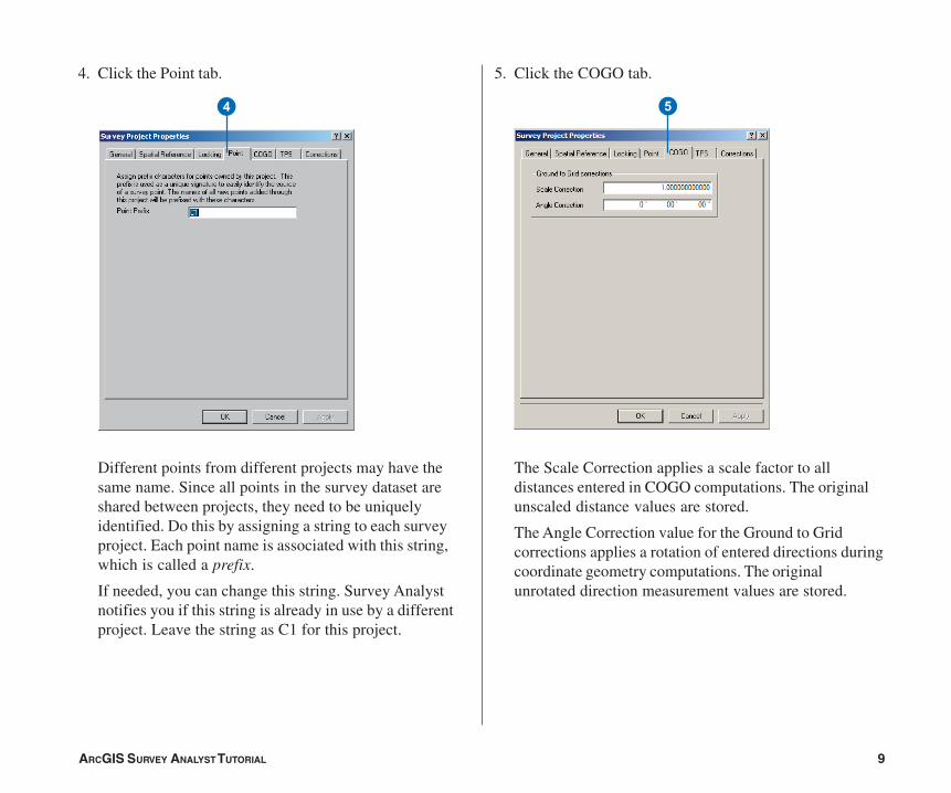
4. Click the Point tab.
Different points from different projects may have thesame name. Since all points in the survey dataset areshared between projects, they need to be uniquelyidentified. Do this by assigning a string to each surveyproject. Each point name is associated with this string,which is called a prefix.
If needed, you can change this string. Survey Analystnotifies you if this string is already in use by a differentproject. Leave the string as C1 for this project.
5. Click the COGO tab.
The Scale Correction applies a scale factor to alldistances entered in COGO computations. The originalunscaled distance values are stored.
The Angle Correction value for the Ground to Gridcorrections applies a rotation of entered directions duringcoordinate geometry computations. The originalunrotated direction measurement values are stored.
4 5
Ch02.pmd 05/18/2006, 3:40 PM9

10 ARCGIS SURVEY ANALYST TUTORIAL
6. Click the TPS tab.
Standard deviations are used to define the expected levelof precision in calibrated measuring devices.
The values on this tab are the default standard deviationsassigned in new computations that use measurementsfrom total station equipment. When working withspecific computations, you can either accept or changethese standard deviations.
If needed, on this property tab you can also change thedefaults used by projects.
You do not need to change the default standarddeviations for this project.
8
76
7. Click the Corrections tab.
These correction methods are used in computations totake into account the effects of meridian convergence,meteorological conditions, and height above sea level onthe computed coordinates. The original measurementvalues entered into the system are not altered by thesecorrections.
You do not need to change or assign correction methodsfor this project; only the Basic Sea Level Correction isrequired.
8. Click OK.
Ch02.pmd 05/18/2006, 3:40 PM10
ARCGIS SURVEY ANALYST TUTORIAL 11
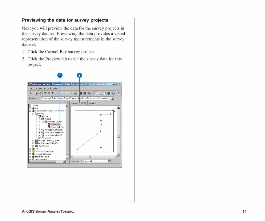
Previewing the data for survey projects
Next you will preview the data for the survey projects inthe survey dataset. Previewing the data provides a visualrepresentation of the survey measurements in the surveydataset.
1. Click the Carmel Bay survey project.
2. Click the Preview tab to see the survey data for thisproject.
1 2
Ch02.pmd 05/18/2006, 3:40 PM11
12 ARCGIS SURVEY ANALYST TUTORIAL
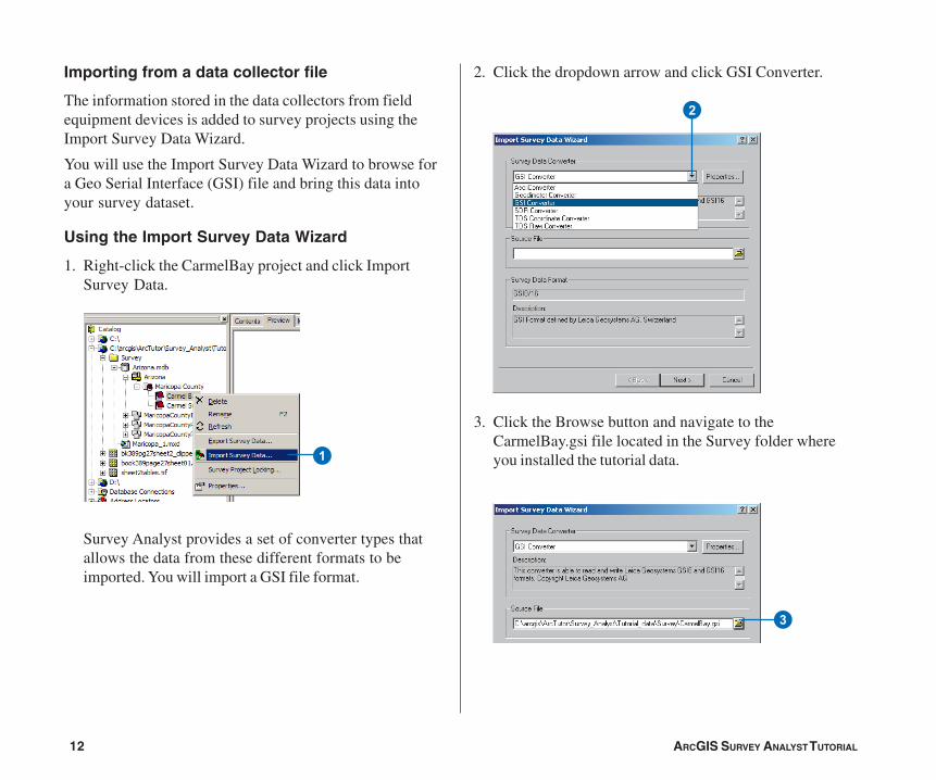
Importing from a data collector file
The information stored in the data collectors from fieldequipment devices is added to survey projects using theImport Survey Data Wizard.
You will use the Import Survey Data Wizard to browse fora Geo Serial Interface (GSI) file and bring this data intoyour survey dataset.
Using the Import Survey Data Wizard
1. Right-click the CarmelBay project and click ImportSurvey Data.
Survey Analyst provides a set of converter types thatallows the data from these different formats to beimported. You will import a GSI file format.
2
3
1
2. Click the dropdown arrow and click GSI Converter.
3. Click the Browse button and navigate to theCarmelBay.gsi file located in the Survey folder whereyou installed the tutorial data.
Ch02.pmd 05/18/2006, 3:40 PM12
ARCGIS SURVEY ANALYST TUTORIAL 13
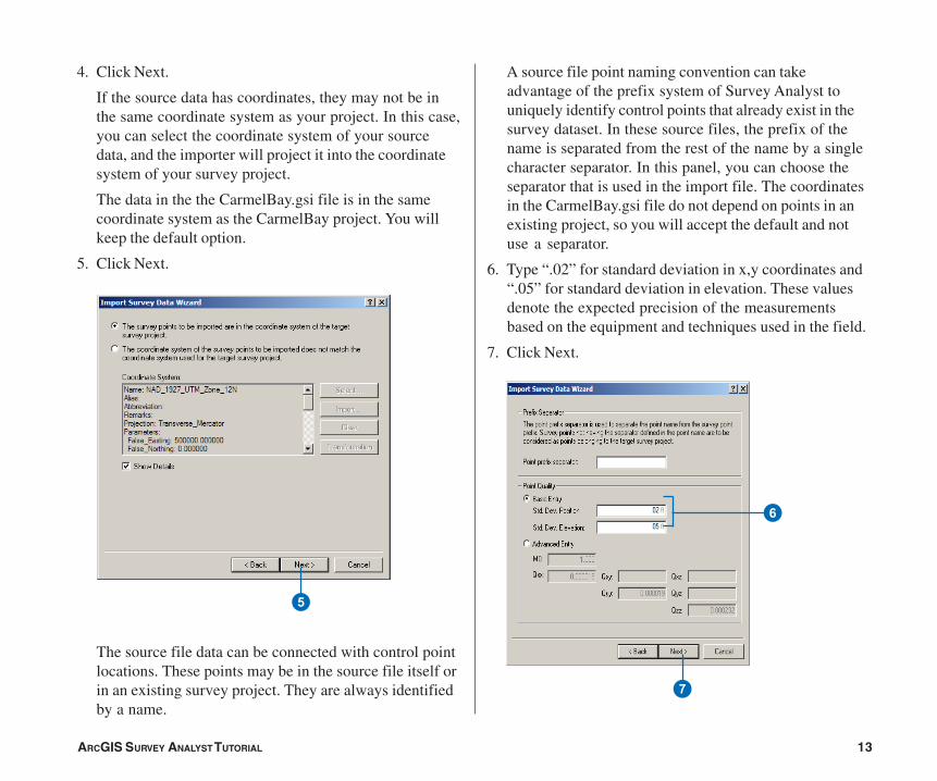
4. Click Next.
If the source data has coordinates, they may not be inthe same coordinate system as your project. In this case,you can select the coordinate system of your sourcedata, and the importer will project it into the coordinatesystem of your survey project.
The data in the the CarmelBay.gsi file is in the samecoordinate system as the CarmelBay project. You willkeep the default option.
5. Click Next.
The source file data can be connected with control pointlocations. These points may be in the source file itself orin an existing survey project. They are always identifiedby a name.
A source file point naming convention can takeadvantage of the prefix system of Survey Analyst touniquely identify control points that already exist in thesurvey dataset. In these source files, the prefix of thename is separated from the rest of the name by a singlecharacter separator. In this panel, you can choose theseparator that is used in the import file. The coordinatesin the CarmelBay.gsi file do not depend on points in anexisting project, so you will accept the default and notuse a separator.
6. Type “.02” for standard deviation in x,y coordinates and“.05” for standard deviation in elevation. These valuesdenote the expected precision of the measurementsbased on the equipment and techniques used in the field.
7. Click Next.
5
7
6
Ch02.pmd 05/18/2006, 3:40 PM13
14 ARCGIS SURVEY ANALYST TUTORIAL
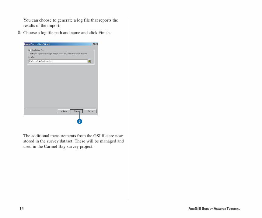
You can choose to generate a log file that reports theresults of the import.
8. Choose a log file path and name and click Finish.
The additional measurements from the GSI file are nowstored in the survey dataset. These will be managed andused in the Carmel Bay survey project.
8
Ch02.pmd 05/18/2006, 3:40 PM14
ARCGIS SURVEY ANALYST TUTORIAL 15
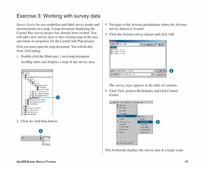
Exercise 3: Working with survey data
Survey layers let you symbolize and label survey points andmeasurements on a map. A map document displaying theCarmel Bay survey project has already been created. Youwill add a new survey layer to this existing map of the areaand refine its properties for the Carmel Sub Plan project.
First you must open the map document. You will do thisfrom ArcCatalog.
1. Double-click the Maricopa_1.mxd map document.
ArcMap starts and displays a map of the survey area.
2. Click the Add Data button.
3. Navigate to the Arizona geodatabase where the Arizonasurvey dataset is located.
4. Click the Arizona survey dataset and click Add.
The survey layer appears in the table of contents.
5. Click View, point to Bookmarks, and click ControlExtent.
This bookmark displays the survey area at a larger scale.
1
2
4
5
Ch02.pmd 05/18/2006, 3:40 PM15
16 ARCGIS SURVEY ANALYST TUTORIAL
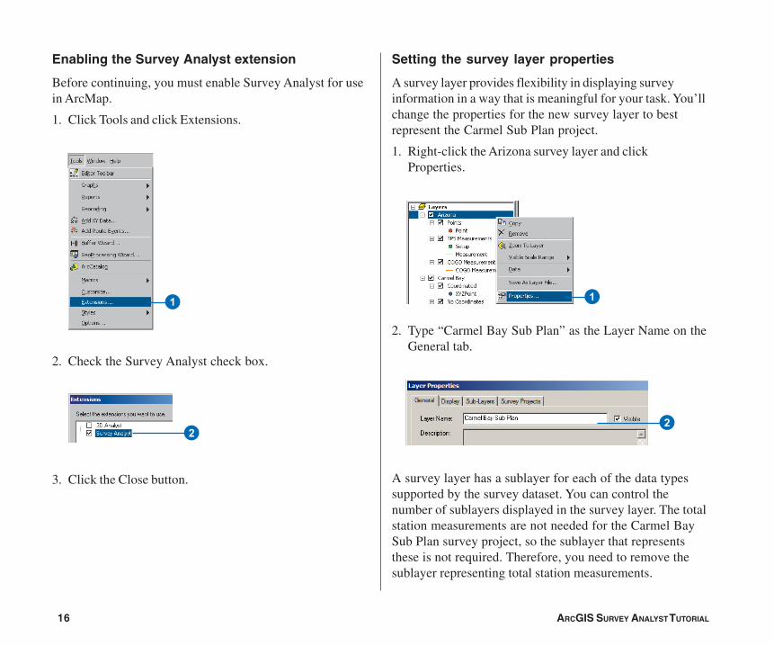
Enabling the Survey Analyst extension
Before continuing, you must enable Survey Analyst for usein ArcMap.
1. Click Tools and click Extensions.
2. Check the Survey Analyst check box.
3. Click the Close button.
Setting the survey layer properties
A survey layer provides flexibility in displaying surveyinformation in a way that is meaningful for your task. You’llchange the properties for the new survey layer to bestrepresent the Carmel Sub Plan project.
1. Right-click the Arizona survey layer and clickProperties.
2. Type “Carmel Bay Sub Plan” as the Layer Name on theGeneral tab.
A survey layer has a sublayer for each of the data typessupported by the survey dataset. You can control thenumber of sublayers displayed in the survey layer. The totalstation measurements are not needed for the Carmel BaySub Plan survey project, so the sublayer that representsthese is not required. Therefore, you need to remove thesublayer representing total station measurements.
2
11
2
Ch02.pmd 05/18/2006, 3:40 PM16
ARCGIS SURVEY ANALYST TUTORIAL 17
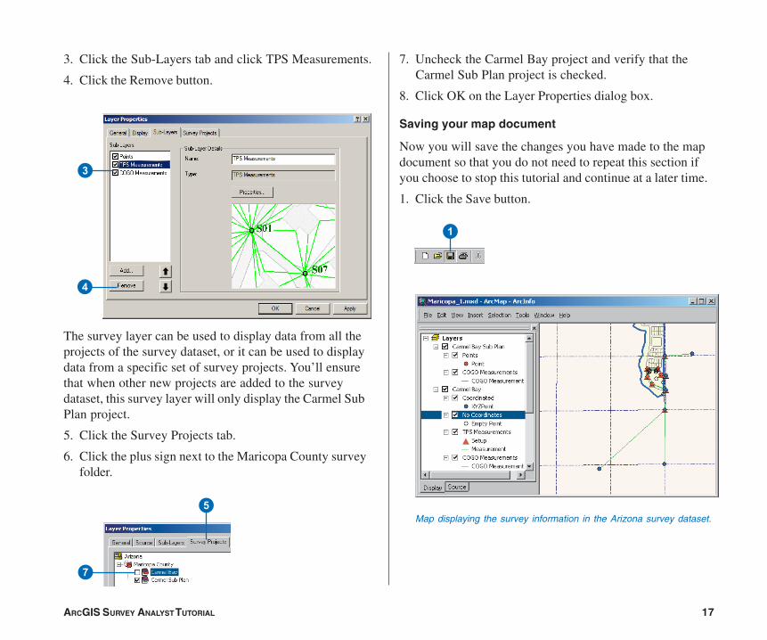
3. Click the Sub-Layers tab and click TPS Measurements.
4. Click the Remove button.
The survey layer can be used to display data from all theprojects of the survey dataset, or it can be used to displaydata from a specific set of survey projects. You’ll ensurethat when other new projects are added to the surveydataset, this survey layer will only display the Carmel SubPlan project.
5. Click the Survey Projects tab.
6. Click the plus sign next to the Maricopa County surveyfolder.
7. Uncheck the Carmel Bay project and verify that theCarmel Sub Plan project is checked.
8. Click OK on the Layer Properties dialog box.
Saving your map document
Now you will save the changes you have made to the mapdocument so that you do not need to repeat this section ifyou choose to stop this tutorial and continue at a later time.
1. Click the Save button.
7
5
1
Map displaying the survey information in the Arizona survey dataset.
3
4
Ch02.pmd 05/18/2006, 3:40 PM17
18 ARCGIS SURVEY ANALYST TUTORIAL
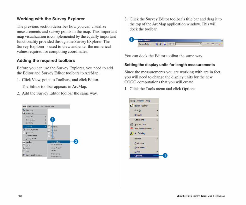
Working with the Survey Explorer
The previous section describes how you can visualizemeasurements and survey points in the map. This importantmap visualization is complemented by the equally importantfunctionality provided through the Survey Explorer. TheSurvey Explorer is used to view and enter the numericalvalues required for computing coordinates.
Adding the required toolbars
Before you can use the Survey Explorer, you need to addthe Editor and Survey Editor toolbars to ArcMap.
1. Click View, point to Toolbars, and click Editor.
The Editor toolbar appears in ArcMap.
2. Add the Survey Editor toolbar the same way.
3. Click the Survey Editor toolbar’s title bar and drag it tothe top of the ArcMap application window. This willdock the toolbar.
You can dock the Editor toolbar the same way.
Setting the display units for length measurements
Since the measurements you are working with are in feet,you will need to change the display units for the newCOGO computations that you will create.
1. Click the Tools menu and click Options.
2
1
3
1
Ch02.pmd 05/18/2006, 3:40 PM18
ARCGIS SURVEY ANALYST TUTORIAL 19
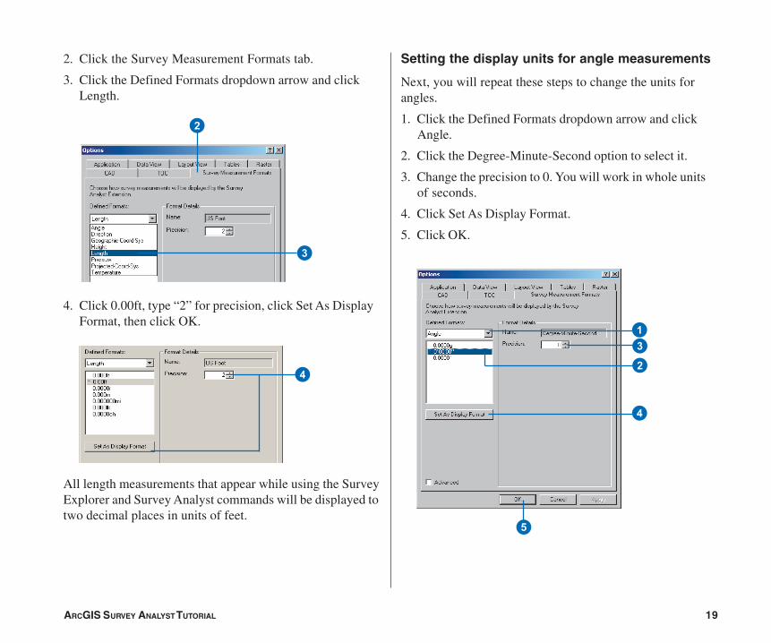
2. Click the Survey Measurement Formats tab.
3. Click the Defined Formats dropdown arrow and clickLength.
4. Click 0.00ft, type “2” for precision, click Set As DisplayFormat, then click OK.
All length measurements that appear while using the SurveyExplorer and Survey Analyst commands will be displayed totwo decimal places in units of feet.
Setting the display units for angle measurements
Next, you will repeat these steps to change the units forangles.
1. Click the Defined Formats dropdown arrow and clickAngle.
2. Click the Degree-Minute-Second option to select it.
3. Change the precision to 0. You will work in whole unitsof seconds.
4. Click Set As Display Format.
5. Click OK.
2
3
1
2
3
4
5
4
Ch02.pmd 05/18/2006, 3:40 PM19
20 ARCGIS SURVEY ANALYST TUTORIAL
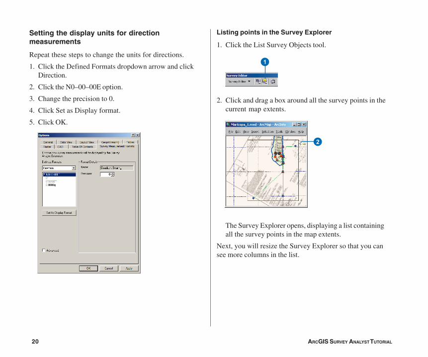
Listing points in the Survey Explorer
1. Click the List Survey Objects tool.
2. Click and drag a box around all the survey points in thecurrent map extents.
The Survey Explorer opens, displaying a list containingall the survey points in the map extents.
Next, you will resize the Survey Explorer so that you cansee more columns in the list.
1
2
Setting the display units for directionmeasurements
Repeat these steps to change the units for directions.
1. Click the Defined Formats dropdown arrow and clickDirection.
2. Click the N0–00–00E option.
3. Change the precision to 0.
4. Click Set as Display format.
5. Click OK.
Ch02.pmd 05/18/2006, 3:40 PM20
ARCGIS SURVEY ANALYST TUTORIAL 21
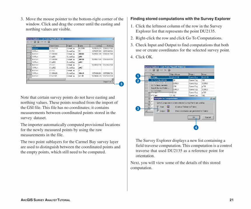
Finding stored computations with the Survey Explorer
1. Click the leftmost column of the row in the SurveyExplorer list that represents the point DU2135.
2. Right-click the row and click Go To Computations.
3. Check Input and Output to find computations that bothuse or create coordinates for the selected survey point.
4. Click OK.
The Survey Explorer displays a new list containing afield traverse computation. This computation is a controltraverse that used DU2135 as a reference point fororientation.
Next, you will view some of the details of this storedcomputation.
12
4
3
3. Move the mouse pointer to the bottom-right corner of thewindow. Click and drag the corner until the easting andnorthing values are visible.
Note that certain survey points do not have easting andnorthing values. These points resulted from the import ofthe GSI file. This file has no coordinates; it containsmeasurements between coordinated points stored in thesurvey dataset.
The importer automatically computed provisional locationsfor the newly measured points by using the rawmeasurements in the file.
The two point sublayers for the Carmel Bay survey layerare used to distinguish between the coordinated points andthe empty points, which still need to be computed.
3
Ch02.pmd 05/18/2006, 3:40 PM21
22 ARCGIS SURVEY ANALYST TUTORIAL
3. Click the Setup tab.
The Setup tab displays all the instrument setupsprocessed in this traverse.
3
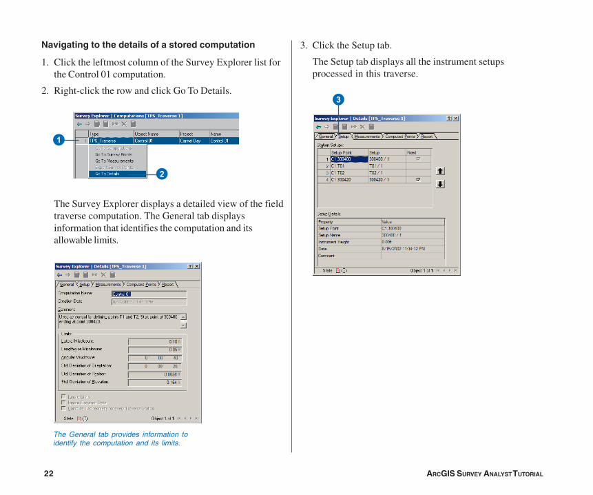
Navigating to the details of a stored computation
1. Click the leftmost column of the Survey Explorer list forthe Control 01 computation.
2. Right-click the row and click Go To Details.
The Survey Explorer displays a detailed view of the fieldtraverse computation. The General tab displaysinformation that identifies the computation and itsallowable limits.
1
2
The General tab provides information toidentify the computation and its limits.
Ch02.pmd 05/18/2006, 3:40 PM22
ARCGIS SURVEY ANALYST TUTORIAL 23
Editing survey data
Computing coordinates and analyzing coordinate quality isthe most important feature of Survey Analyst.
In this exercise, you will define computations to calculatecoordinates for points, link a parcel block feature to points,and update the feature’s location. To do this, you will addyour imported measurements to a new computation.
Starting an edit session and setting the editingenvironment
Before you start defining computations, you need to starteditng and also set the Target project for your edits.
Adding an edit task
1. Click the Editor menu and click Start Editing.
If the Starting To Edit In A Different Coordinate Systemdialog box appears, click Start Editing.
1
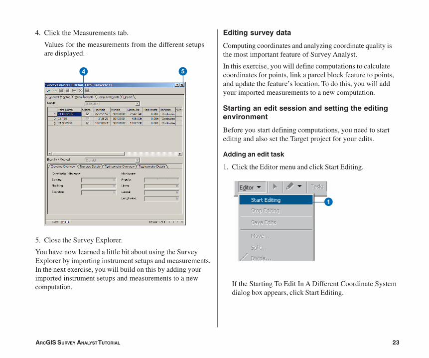
4. Click the Measurements tab.
Values for the measurements from the different setupsare displayed.
5. Close the Survey Explorer.
You have now learned a little bit about using the SurveyExplorer by importing instrument setups and measurements.In the next exercise, you will build on this by adding yourimported instrument setups and measurements to a newcomputation.
4 5
Ch02.pmd 05/18/2006, 3:40 PM23
24 ARCGIS SURVEY ANALYST TUTORIAL
Creating a new field traverse computation
To calculate coordinates for the measured points, twotraverse computations will be used. The first traverse hasalready been defined; this is the computation you found inthe previous exercise. It was used to extend control into theproject area, and it created two new survey points: T1 andT2.
You will now create a second field traverse computation tocalculate coordinates for control points T3–T7. Additionalmeasurements were also imported as part of the GSI fileand were used to calculate coordinates for building cornersand found parcel corner monuments in the project area.
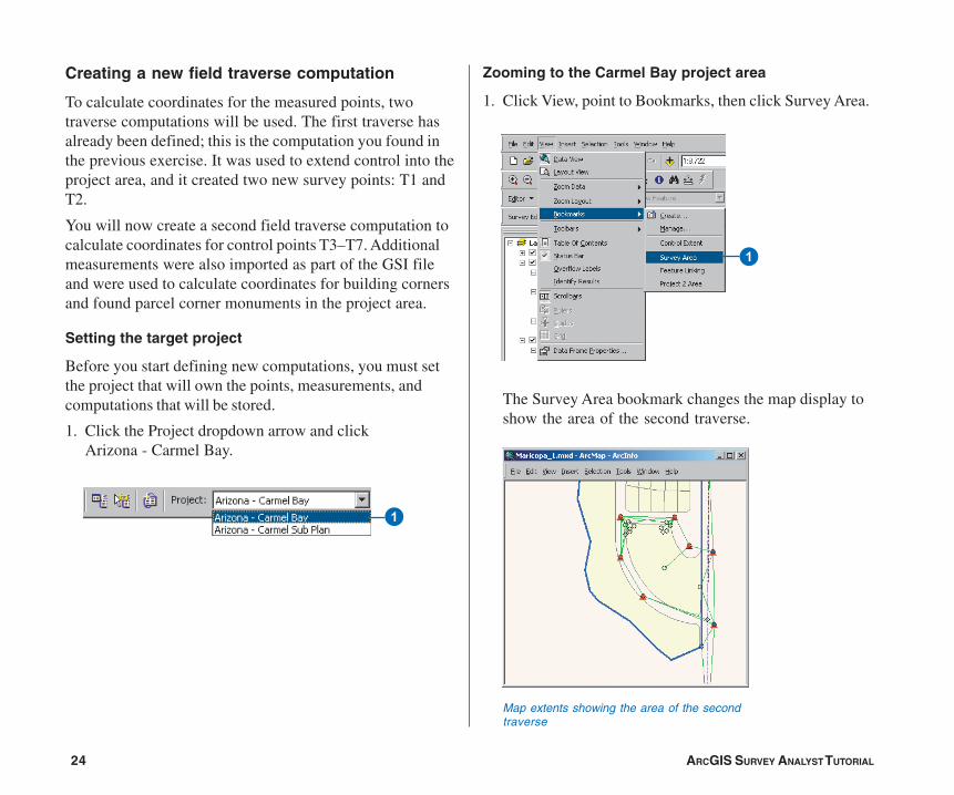
Setting the target project
Before you start defining new computations, you must setthe project that will own the points, measurements, andcomputations that will be stored.
1. Click the Project dropdown arrow and clickArizona - Carmel Bay.
Zooming to the Carmel Bay project area
1. Click View, point to Bookmarks, then click Survey Area.
The Survey Area bookmark changes the map display toshow the area of the second traverse.
1
1
Map extents showing the area of the secondtraverse
Ch02.pmd 05/18/2006, 3:40 PM24

ARCGIS SURVEY ANALYST TUTORIAL 25
Defining the second traverse and side-shots
1. Click the tool palette dropdown arrow, point to the TPSComputations button, and click the Traverse button.
The Survey Explorer appears with pages for a new fieldtraverse.
2. Type “Control 02” for the traverse name. You will usethis name again later to find this computation.
3. Type “Traverse T02 to T01” for the comment.
4. Type “0.200” for Lateral Misclosure and “0.2” forLengthwise Misclosure.
5. Check Compute Tacheometry for every TraverseStation.
6. Click the Setup tab.
7. Snap to and click T02 on the map.
8. Press Enter twice to accept the default name and Fixedoption.
9. Add the remaining traverse setups—shown as redtriangles on the map—working in a counterclockwisedirection and ending with T01.
1
9
9
2
3
4
5
6
7
Ch02.pmd 05/18/2006, 3:40 PM25
26 ARCGIS SURVEY ANALYST TUTORIAL
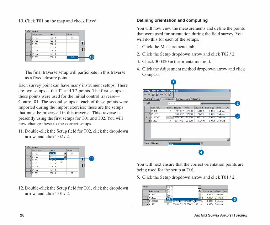
Defining orientation and computing
You will now view the measurements and define the pointsthat were used for orientation during the field survey. Youwill do this for each of the setups.
1. Click the Measurements tab.
2. Click the Setup dropdown arrow and click T02 / 2.
3. Check 300420 in the orientation field.
4. Click the Adjustment method dropdown arrow and clickCompass.
You will next ensure that the correct orientation points arebeing used for the setup at T01.
5. Click the Setup dropdown arrow and click T01 / 2.
10. Click T01 on the map and check Fixed.
The final traverse setup will participate in this traverseas a fixed closure point.
Each survey point can have many instrument setups. Thereare two setups at the T1 and T2 points. The first setups atthese points were used for the initial control traverse—Control 01. The second setups at each of these points wereimported during the import exercise; these are the setupsthat must be processed in this traverse. This traverse ispresently using the first setups for T01 and T02. You willnow change these to the correct setups.
11. Double-click the Setup field for T02, click the dropdownarrow, and click T02 / 2.
12. Double-click the Setup field for T01, click the dropdownarrow, and click T01 / 2.
Q
W
5
1
3
4
2
Ch02.pmd 05/18/2006, 3:40 PM26
ARCGIS SURVEY ANALYST TUTORIAL 27
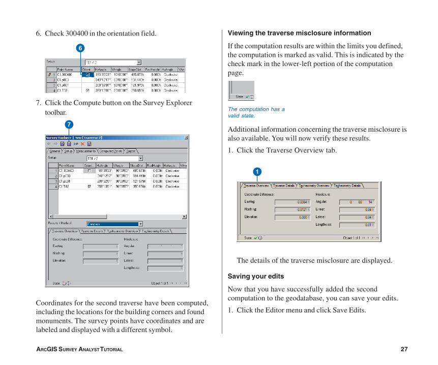
6. Check 300400 in the orientation field.
7. Click the Compute button on the Survey Explorertoolbar.
Coordinates for the second traverse have been computed,including the locations for the building corners and foundmonuments. The survey points have coordinates and arelabeled and displayed with a different symbol.
Viewing the traverse misclosure information
If the computation results are within the limits you defined,the computation is marked as valid. This is indicated by thecheck mark in the lower-left portion of the computationpage.
Additional information concerning the traverse misclosure isalso available. You will now verify these results.
1. Click the Traverse Overview tab.
The details of the traverse misclosure are displayed.
Saving your edits
Now that you have successfully added the secondcomputation to the geodatabase, you can save your edits.
1. Click the Editor menu and click Save Edits.
6
7
The computation has avalid state.
1
Ch02.pmd 05/18/2006, 3:40 PM27
28 ARCGIS SURVEY ANALYST TUTORIAL
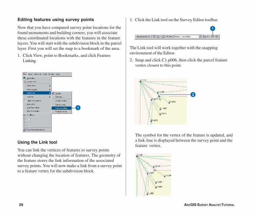
1. Click the Link tool on the Survey Editor toolbar.
The Link tool will work together with the snappingenvironment of the Editor.
2. Snap and click C1.p006, then click the parcel featurevertex closest to this point.
The symbol for the vertex of the feature is updated, anda link-line is displayed between the survey point and thefeature vertex.
Editing features using survey points
Now that you have computed survey point locations for thefound monuments and building corners, you will associatethese coordinated locations with the features in the featurelayers. You will start with the subdivision block in the parcellayer. First you will set the map to a bookmark of the area.
1. Click View, point to Bookmarks, and click FeatureLinking.
Using the Link tool
You can link the vertices of features to survey pointswithout changing the location of features. The geometry ofthe feature stores the link information of the associatedsurvey points. You will now make a link from a survey pointto a feature vertex for the subdivision block.
1
1
2
Ch02.pmd 05/18/2006, 3:40 PM28
ARCGIS SURVEY ANALYST TUTORIAL 29
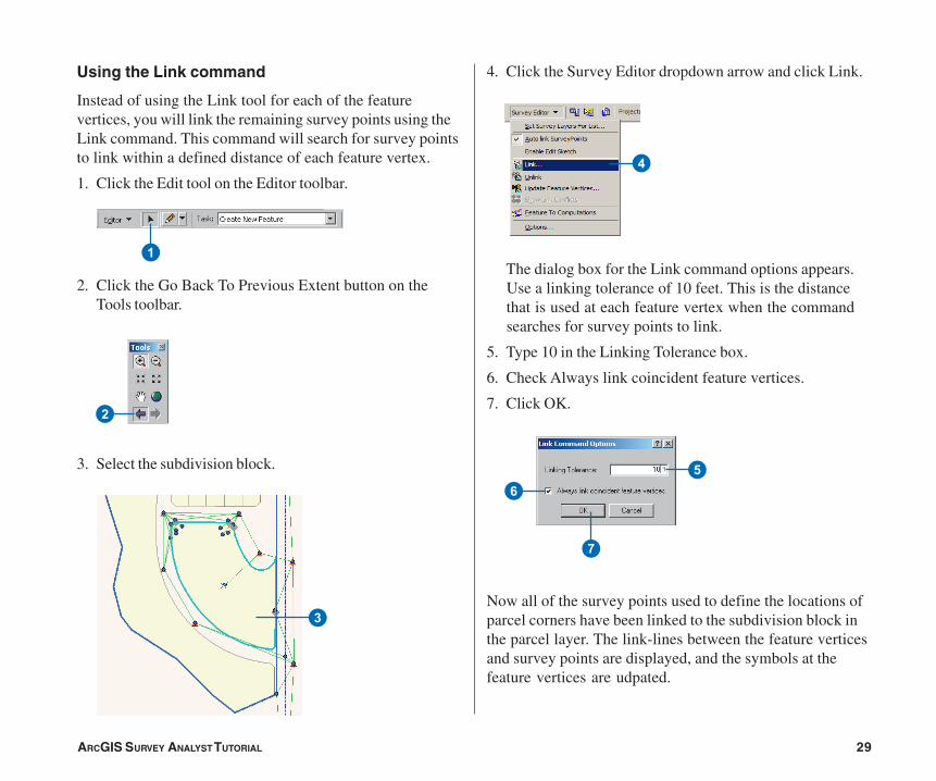
Using the Link command
Instead of using the Link tool for each of the featurevertices, you will link the remaining survey points using theLink command. This command will search for survey pointsto link within a defined distance of each feature vertex.
1. Click the Edit tool on the Editor toolbar.
2. Click the Go Back To Previous Extent button on theTools toolbar.
3. Select the subdivision block.
4. Click the Survey Editor dropdown arrow and click Link.
The dialog box for the Link command options appears.Use a linking tolerance of 10 feet. This is the distancethat is used at each feature vertex when the commandsearches for survey points to link.
5. Type 10 in the Linking Tolerance box.
6. Check Always link coincident feature vertices.
7. Click OK.
Now all of the survey points used to define the locations ofparcel corners have been linked to the subdivision block inthe parcel layer. The link-lines between the feature verticesand survey points are displayed, and the symbols at thefeature vertices are udpated.
1
2
3
56
7
4
Ch02.pmd 05/18/2006, 3:40 PM29
30 ARCGIS SURVEY ANALYST TUTORIAL
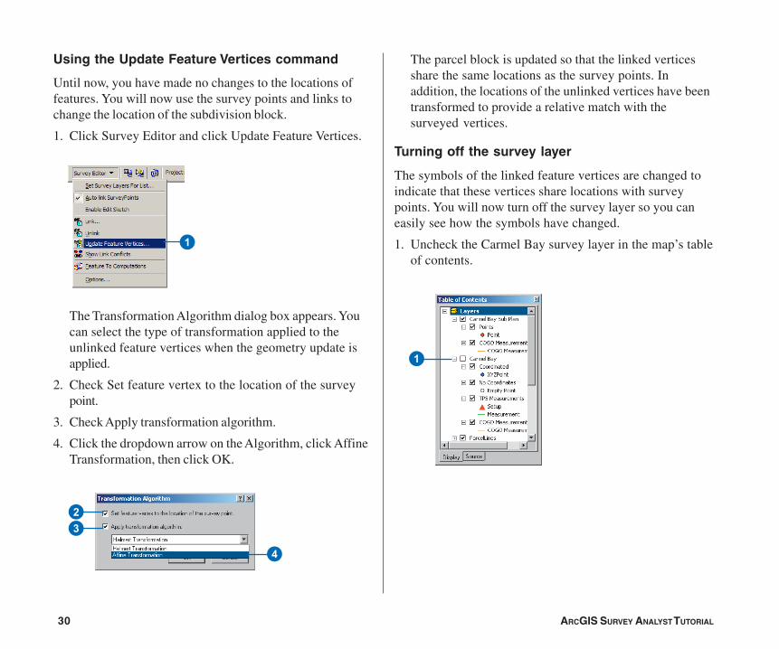
Using the Update Feature Vertices command
Until now, you have made no changes to the locations offeatures. You will now use the survey points and links tochange the location of the subdivision block.
1. Click Survey Editor and click Update Feature Vertices.
The Transformation Algorithm dialog box appears. Youcan select the type of transformation applied to theunlinked feature vertices when the geometry update isapplied.
2. Check Set feature vertex to the location of the surveypoint.
3. Check Apply transformation algorithm.
4. Click the dropdown arrow on the Algorithm, click AffineTransformation, then click OK.
The parcel block is updated so that the linked verticesshare the same locations as the survey points. Inaddition, the locations of the unlinked vertices have beentransformed to provide a relative match with thesurveyed vertices.
Turning off the survey layer
The symbols of the linked feature vertices are changed toindicate that these vertices share locations with surveypoints. You will now turn off the survey layer so you caneasily see how the symbols have changed.
1. Uncheck the Carmel Bay survey layer in the map’s tableof contents.
1
4
23
1
Ch02.pmd 05/18/2006, 3:40 PM30

ARCGIS SURVEY ANALYST TUTORIAL 31
The map displays only the features and the link symbolsfor the vertices of the linked feature.
Saving your edits and your map document
Now that you have updated the parcel feature in yourgeodatabase, you can save your edits.
1. Click Editor in the Editor toolbar and click Save Edits.
2. Click the Save button to save your map document.
Ch02.pmd 05/18/2006, 3:40 PM31
32 ARCGIS SURVEY ANALYST TUTORIAL
Exercise 4: Creating COGO computations
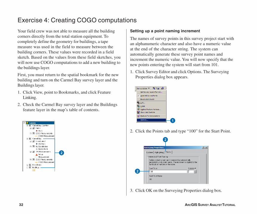
Setting up a point naming increment
The names of survey points in this survey project start withan alphanumeric character and also have a numeric valueat the end of the character string. The system canautomatically generate these survey point names andincrement the numeric value. You will now specify that thenew points entering the system will start from 101.
1. Click Survey Editor and click Options. The SurveyingProperties dialog box appears.
2. Click the Points tab and type “100” for the Start Point.
3. Click OK on the Surveying Properties dialog box.
Your field crew was not able to measure all the buildingcorners directly from the total station equipment. Tocompletely define the geometry for buildings, a tapemeasure was used in the field to measure between thebuilding corners. These values were recorded in a fieldsketch. Based on the values from these field sketches, youwill now use COGO computations to add a new building tothe buildings layer.
First, you must return to the spatial bookmark for the newbuilding and turn on the Carmel Bay survey layer and theBuildings layer.
1. Click View, point to Bookmarks, and click FeatureLinking.
2. Check the Carmel Bay survey layer and the Buildingsfeature layer in the map’s table of contents.
2
1
2
2
Ch02.pmd 05/18/2006, 3:40 PM32
ARCGIS SURVEY ANALYST TUTORIAL 33
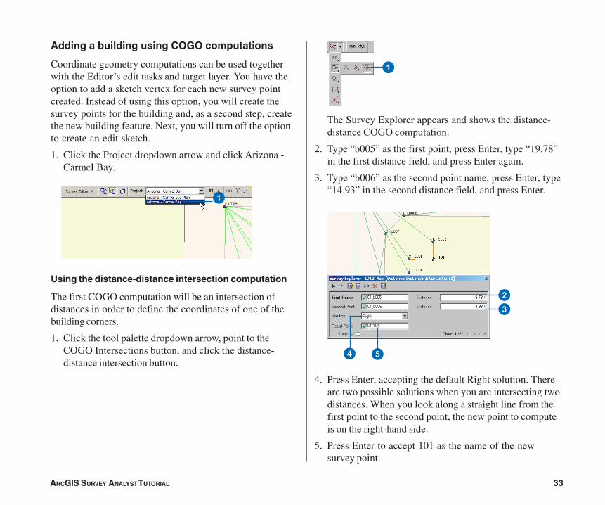
Adding a building using COGO computations
Coordinate geometry computations can be used togetherwith the Editor’s edit tasks and target layer. You have theoption to add a sketch vertex for each new survey pointcreated. Instead of using this option, you will create thesurvey points for the building and, as a second step, createthe new building feature. Next, you will turn off the optionto create an edit sketch.
1. Click the Project dropdown arrow and click Arizona -Carmel Bay.
Using the distance-distance intersection computation
The first COGO computation will be an intersection ofdistances in order to define the coordinates of one of thebuilding corners.
1. Click the tool palette dropdown arrow, point to theCOGO Intersections button, and click the distance-distance intersection button.
The Survey Explorer appears and shows the distance-distance COGO computation.
2. Type “b005” as the first point, press Enter, type “19.78”in the first distance field, and press Enter again.
3. Type “b006” as the second point name, press Enter, type“14.93” in the second distance field, and press Enter.
4. Press Enter, accepting the default Right solution. Thereare two possible solutions when you are intersecting twodistances. When you look along a straight line from thefirst point to the second point, the new point to computeis on the right-hand side.
5. Press Enter to accept 101 as the name of the newsurvey point.
1
23
4 5
1
Ch02.pmd 05/18/2006, 3:40 PM33

34 ARCGIS SURVEY ANALYST TUTORIAL
Adding the final building corner
You will now add a second distance-distance intersectioncomputation to add the final building corner.
1. Click the tool palette dropdown arrow, point to theCOGO Intersections button, and click the Distance-Distance intersection button.
The first point of the new computation is, by default, the lastpoint that was computed.
2. Press Enter to accept point 102 as the first point, type“26.71” as the first distance, and press Enter.
3. Type “b004” as the second point name.
4. Type “43.04” as the second distance.
5. Click the Solution dropdown arrow and click Left.
6. Press Enter to accept 103 as the new point name.
Using the deflection angle distance computation
On the field sketch for the building, an assumption is madethat the building walls are orthogonal to each other. Forthe next measured building corner, this assumption is used inthe deflection angle distance COGO computation.
1. Click the tool palette dropdown arrow, point to theCOGO Basic Computations button, and click theDeflection-Angle-Distance button.
The Deflection-Angle-Distance computation is displayedin the Survey Explorer.
2. Type “b006” as the from point and press Enter.
3. Click survey point 101 on the map to define thereference direction.
4. Type “270” as the deflection angle and press Enter.
5. Type “23.520” as the distance and press Enter.
6. Press Enter to accept 102 as the new point name.
11
245
2
3
45
Ch02.pmd 05/18/2006, 3:40 PM34
ARCGIS SURVEY ANALYST TUTORIAL 35
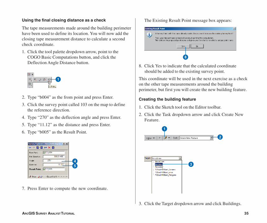
Using the final closing distance as a check
The tape measurements made around the building perimeterhave been used to define its location. You will now add theclosing tape measurement distance to calculate a secondcheck coordinate.
1. Click the tool palette dropdown arrow, point to theCOGO Basic Computations button, and click theDeflection Angle Distance button.
2. Type “b004” as the from point and press Enter.
3. Click the survey point called 103 on the map to definethe reference direction.
4. Type “270” as the deflection angle and press Enter.
5. Type “11.12” as the distance and press Enter.
6. Type “b005” as the Result Point.
7. Press Enter to compute the new coordinate.
The Existing Result Point message box appears:
8. Click Yes to indicate that the calculated coordinateshould be added to the existing survey point.
This coordinate will be used in the next exercise as a checkon the other tape measurements around the buildingperimeter, but first you will create the new building feature.
Creating the building feature
1. Click the Sketch tool on the Editor toolbar.
2. Click the Task dropdown arrow and click Create NewFeature.
3. Click the Target dropdown arrow and click Buildings.
1
8
1
2
45 3
Ch02.pmd 05/18/2006, 3:40 PM35
36 ARCGIS SURVEY ANALYST TUTORIAL
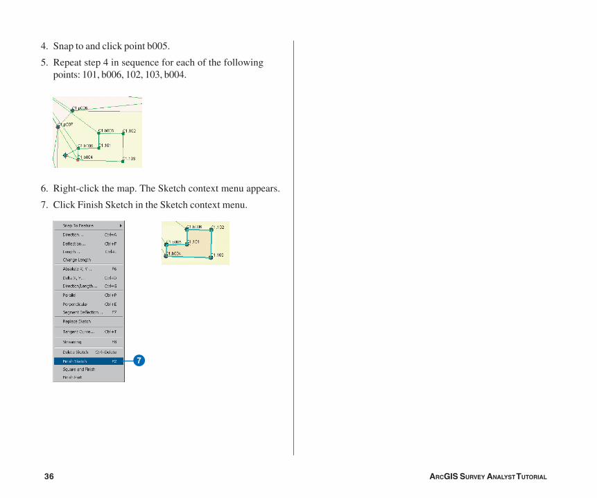
4. Snap to and click point b005.
5. Repeat step 4 in sequence for each of the followingpoints: 101, b006, 102, 103, b004.
6. Right-click the map. The Sketch context menu appears.
7. Click Finish Sketch in the Sketch context menu.
7
Ch02.pmd 05/18/2006, 3:40 PM36
ARCGIS SURVEY ANALYST TUTORIAL 37
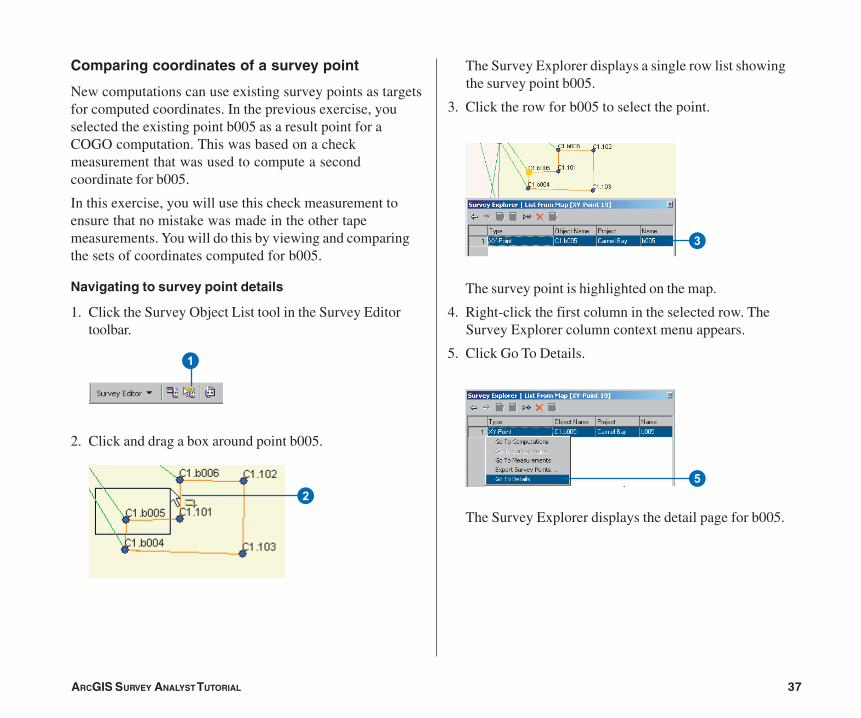
Comparing coordinates of a survey point
New computations can use existing survey points as targetsfor computed coordinates. In the previous exercise, youselected the existing point b005 as a result point for aCOGO computation. This was based on a checkmeasurement that was used to compute a secondcoordinate for b005.
In this exercise, you will use this check measurement toensure that no mistake was made in the other tapemeasurements. You will do this by viewing and comparingthe sets of coordinates computed for b005.
Navigating to survey point details
1. Click the Survey Object List tool in the Survey Editortoolbar.
2. Click and drag a box around point b005.
The Survey Explorer displays a single row list showingthe survey point b005.
3. Click the row for b005 to select the point.
The survey point is highlighted on the map.
4. Right-click the first column in the selected row. TheSurvey Explorer column context menu appears.
5. Click Go To Details.
The Survey Explorer displays the detail page for b005.2
1
3
5
Ch02.pmd 05/18/2006, 3:40 PM37
38 ARCGIS SURVEY ANALYST TUTORIAL
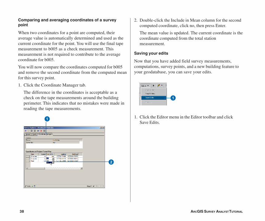
Comparing and averaging coordinates of a surveypoint
When two coordinates for a point are computed, theiraverage value is automatically determined and used as thecurrent coordinate for the point. You will use the final tapemeasurement to b005 as a check measurement. Thismeasurement is not required to contribute to the averagecoordinate for b005.
You will now compare the coordinates computed for b005and remove the second coordinate from the computed meanfor this survey point.
1. Click the Coordinate Manager tab.
The difference in the coordinates is acceptable as acheck on the tape measurements around the buildingperimeter. This indicates that no mistakes were made inreading the tape measurements.
2. Double-click the Include in Mean column for the secondcomputed coordinate, click no, then press Enter.
The mean value is updated. The current coordinate is thecoordinate computed from the total stationmeasurement.
Saving your edits
Now that you have added field survey measurements,computations, survey points, and a new building feature toyour geodatabase, you can save your edits.
1. Click the Editor menu in the Editor toolbar and clickSave Edits.
1
2
1
Ch02.pmd 05/18/2006, 3:40 PM38
ARCGIS SURVEY ANALYST TUTORIAL 39
Entering COGO from plan data
When your organization does not have coordinates for theparcel corners represented on a subdivision plan, usingCOGO computations is one method to calculate them. Youwill now use the dimensions available on Sheet 2 of theCarmel Bay subdivision plan to get approximate coordinatesfor a parcel monument. Since these computed coordinateswill be based on the survey points measured by your fieldcrew, they can be used to more easily find physicalevidence of this parcel corner, which could not be foundduring the first field survey.
First you will need to go to the Project 2 Area bookmark.
1. Click View, point to Bookmarks, and click Project 2Area.
2. Check Survey Plat Images in the table of contents.
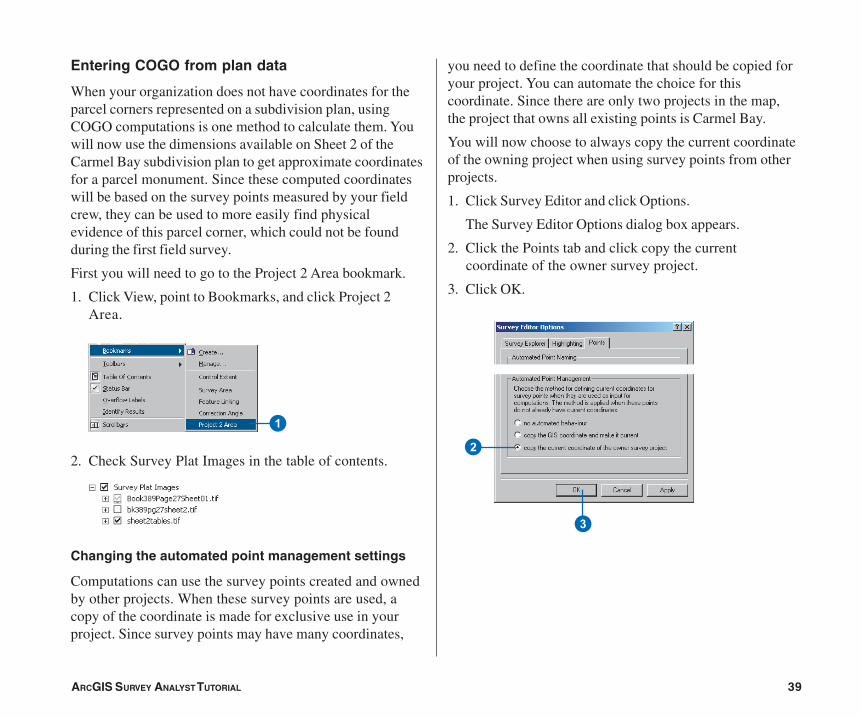
Changing the automated point management settings
Computations can use the survey points created and ownedby other projects. When these survey points are used, acopy of the coordinate is made for exclusive use in yourproject. Since survey points may have many coordinates,
you need to define the coordinate that should be copied foryour project. You can automate the choice for thiscoordinate. Since there are only two projects in the map,the project that owns all existing points is Carmel Bay.
You will now choose to always copy the current coordinateof the owning project when using survey points from otherprojects.
1. Click Survey Editor and click Options.
The Survey Editor Options dialog box appears.
2. Click the Points tab and click copy the currentcoordinate of the owner survey project.
3. Click OK.
1
2
3
Ch02.pmd 05/18/2006, 3:40 PM39
40 ARCGIS SURVEY ANALYST TUTORIAL
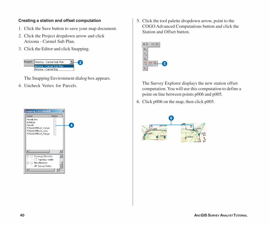
Creating a station and offset computation
1. Click the Save button to save your map document.
2. Click the Project dropdown arrow and clickArizona - Carmel Sub Plan.
3. Click the Editor and click Snapping.
The Snapping Environment dialog box appears.
4. Uncheck Vertex for Parcels.
5. Click the tool palette dropdown arrow, point to theCOGO Advanced Computations button and click theStation and Offset button.
The Survey Explorer displays the new station offsetcomputation. You will use this computation to define apoint on line between points p006 and p005.
6. Click p006 on the map, then click p005.
2
4
5
6
Ch02.pmd 05/18/2006, 3:40 PM40
ARCGIS SURVEY ANALYST TUTORIAL 41
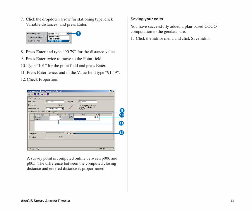
7. Click the dropdown arrow for stationing type, clickVariable distances, and press Enter.
8. Press Enter and type “90.79” for the distance value.
9. Press Enter twice to move to the Point field.
10. Type “101” for the point field and press Enter.
11. Press Enter twice, and in the Value field type “91.49”.
12. Check Proportion.
A survey point is computed online between p006 andp005. The difference between the computed closingdistance and entered distance is proportioned.
7
Q
E
8
W
Saving your edits
You have successfully added a plan-based COGOcomputation to the geodatabase.
1. Click the Editor menu and click Save Edits.
Ch02.pmd 05/18/2006, 3:40 PM41
42 ARCGIS SURVEY ANALYST TUTORIAL
Exercise 5: Updating computations and linked features
In the exercise ‘Working with survey data’, you learnedhow to find stored computations. In this exercise you willdiscover a different method to navigate to an existingcomputation. You will find and make a change to the secondcontrol traverse—Control 02. You have determined that themeasurement to the point 300420 is erroneous and shouldbe disabled.
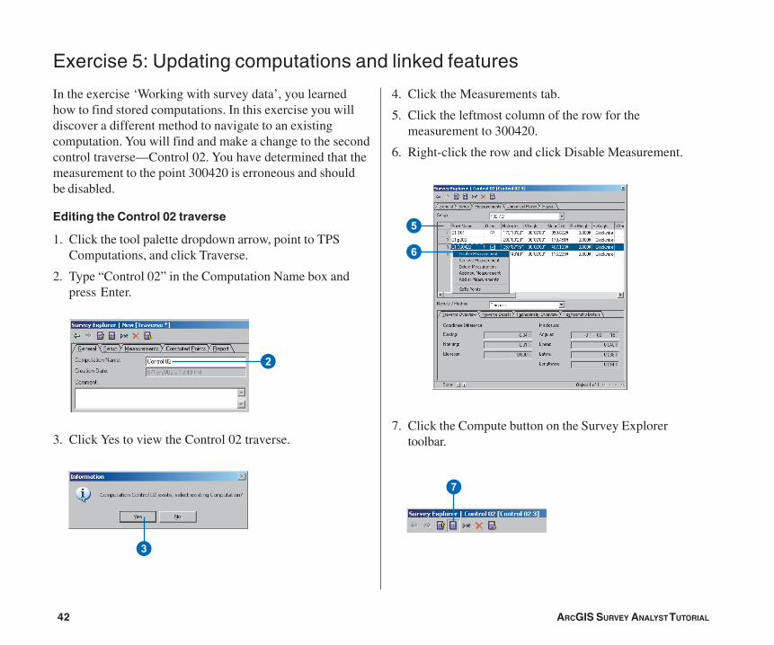
Editing the Control 02 traverse
1. Click the tool palette dropdown arrow, point to TPSComputations, and click Traverse.
2. Type “Control 02” in the Computation Name box andpress Enter.
3. Click Yes to view the Control 02 traverse.
4. Click the Measurements tab.
5. Click the leftmost column of the row for themeasurement to 300420.
6. Right-click the row and click Disable Measurement.
7. Click the Compute button on the Survey Explorertoolbar.
2
5
6
7
3
Ch02.pmd 05/18/2006, 3:40 PM42
ARCGIS SURVEY ANALYST TUTORIAL 43
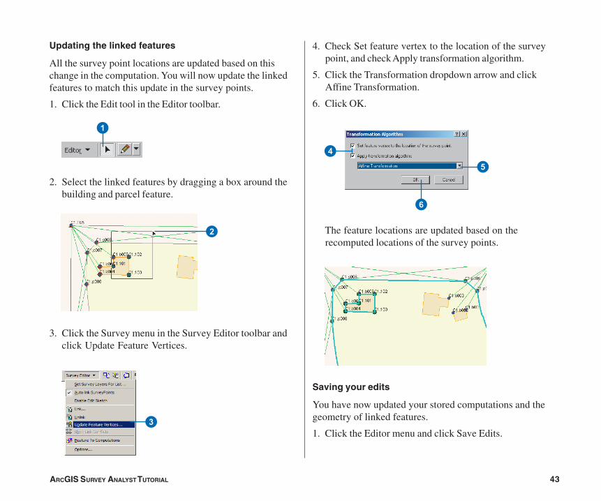
Updating the linked features
All the survey point locations are updated based on thischange in the computation. You will now update the linkedfeatures to match this update in the survey points.
1. Click the Edit tool in the Editor toolbar.
2. Select the linked features by dragging a box around thebuilding and parcel feature.
3. Click the Survey menu in the Survey Editor toolbar andclick Update Feature Vertices.
4. Check Set feature vertex to the location of the surveypoint, and check Apply transformation algorithm.
5. Click the Transformation dropdown arrow and clickAffine Transformation.
6. Click OK.
The feature locations are updated based on therecomputed locations of the survey points.
Saving your edits
You have now updated your stored computations and thegeometry of linked features.
1. Click the Editor menu and click Save Edits.
1
2
3
4
5
6
Ch02.pmd 05/18/2006, 3:40 PM43
44 ARCGIS SURVEY ANALYST TUTORIAL
Exercise 6: Exporting survey point data
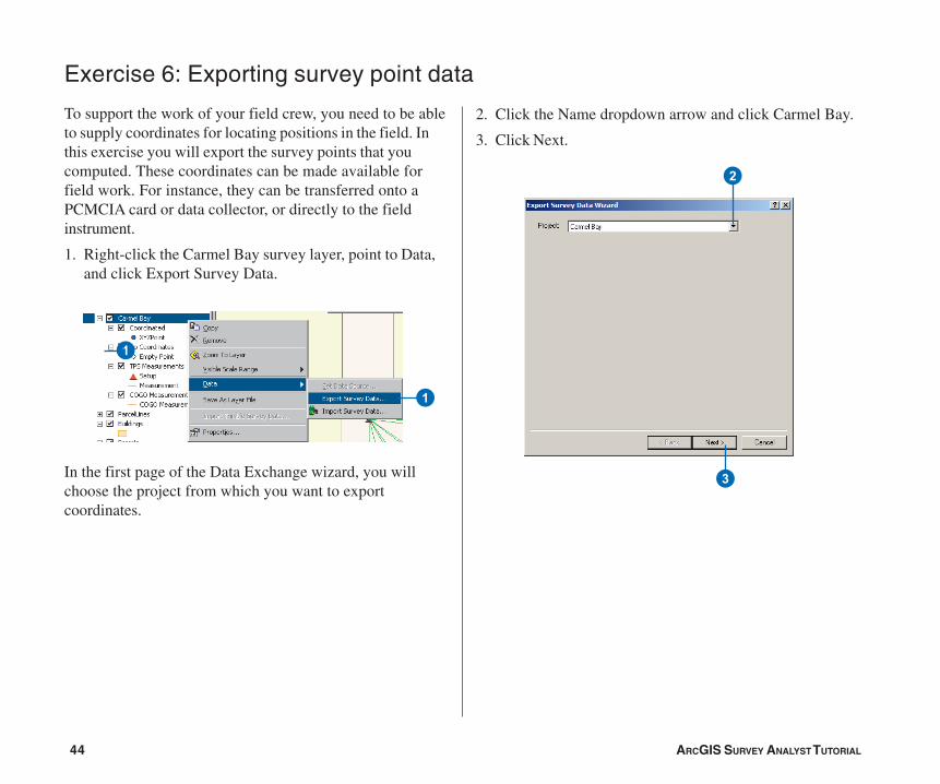
To support the work of your field crew, you need to be ableto supply coordinates for locating positions in the field. Inthis exercise you will export the survey points that youcomputed. These coordinates can be made available forfield work. For instance, they can be transferred onto aPCMCIA card or data collector, or directly to the fieldinstrument.
1. Right-click the Carmel Bay survey layer, point to Data,and click Export Survey Data.
In the first page of the Data Exchange wizard, you willchoose the project from which you want to exportcoordinates.
2. Click the Name dropdown arrow and click Carmel Bay.
3. Click Next.
1
1
2
3
Ch02.pmd 05/18/2006, 3:40 PM44
ARCGIS SURVEY ANALYST TUTORIAL 45
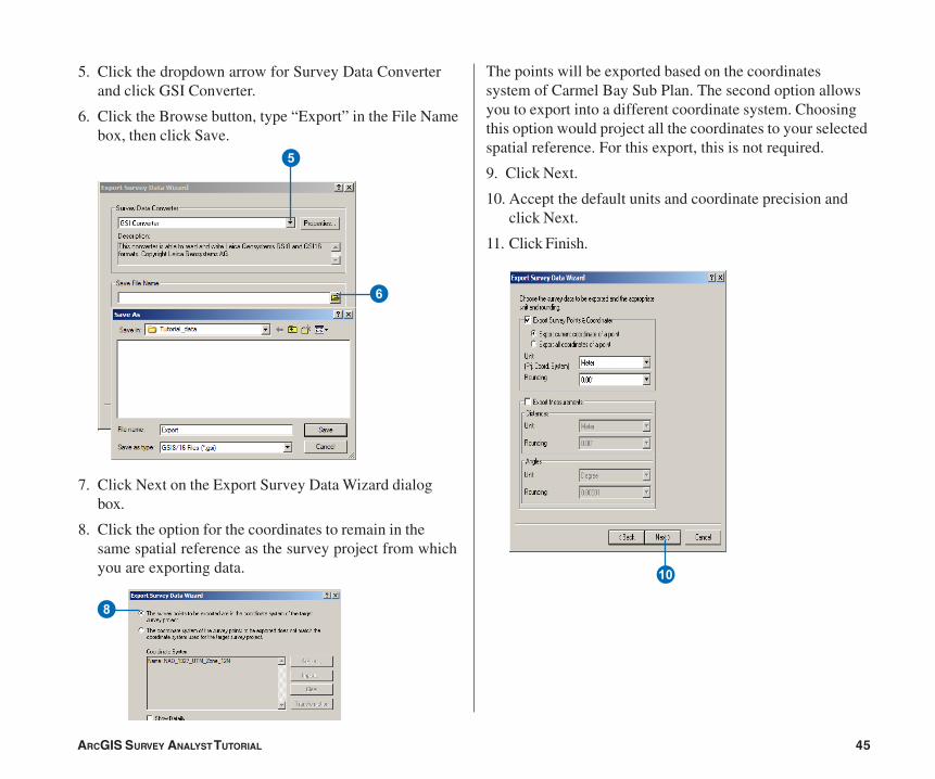
5. Click the dropdown arrow for Survey Data Converterand click GSI Converter.
6. Click the Browse button, type “Export” in the File Namebox, then click Save.
7. Click Next on the Export Survey Data Wizard dialogbox.
8. Click the option for the coordinates to remain in thesame spatial reference as the survey project from whichyou are exporting data.
The points will be exported based on the coordinatessystem of Carmel Bay Sub Plan. The second option allowsyou to export into a different coordinate system. Choosingthis option would project all the coordinates to your selectedspatial reference. For this export, this is not required.
9. Click Next.
10. Accept the default units and coordinate precision andclick Next.
11. Click Finish.
6
5
8
Q
Ch02.pmd 05/18/2006, 3:40 PM45

Ch02.pmd 05/18/2006, 3:40 PM46