Embed Size (px)
Citation preview

Arcade Button Control BoxCreated by Ruiz Brothers
Last updated on 2018-03-22 09:10:12 PM UTC

2444556777
999
10
111111
11121213
1414151516
1717171718
191919202020212122222323
24242424
Guide Contents
Guide ContentsOverview
Custom Controller BoxPrerequisite Guides24mm Arcade ButtonsComponentsTools & Supplies3D Printed CaseNo 3D Printer? No Problem!Ideas, Ideas, Ideas!
Circuit DiagramCircuit DiagramNumber Of ButtonsUSB Power
SoftwareSetup Adafruit Feather M0 Express for CircuitPythonInstall CircuitPython UF2
Download Adafruit CircuitPython HID LibraryUpload The CodeText Document FormattingLine Spaces and Invisible Characters
Modify the CodeChanging Key Presses
Coding VideoPrototyping CircuitTesting LEDs
3D Printing3D Printed PartsFilamentsModify Case DesignUser Parameters
AssemblyInstall FeatherInstall ButtonsWires for GroundMeasure WiresStrip WiresTin WiresSecure BoxButton TinningArcade Button ConnectionsTest Button LEDsCheck Point
WiringHandling WiresConnecting GroundShare Ground
© Adafruit Industries https://learn.adafruit.com/arcade-button-control-box Page 2 of 30

2525262626272728282929
Ground ContinuedLED Wires for AnodeSolder LED Anode ConnectionsButton Wires for SignalSolder Switch WiresConnecting Wires to Adafruit FeatherConnect Ground to FeatherSolder Wires to FeatherWired ConnectionsClose It UpMake, Modify, Share
© Adafruit Industries https://learn.adafruit.com/arcade-button-control-box Page 3 of 30

Overview
Custom Controller Box
In this project, you'll learn how to build a basic USB HID keyboard for triggering things like commands and hotkeys forcontrolling any number of software and hardware. We'll use an Adafruit Feather M0 Express, a handful of arcadebuttons and Circuit Python to make a DIY keyboard controller.
Circuit Python makes this project super simple to program and easy to update - no need for a compiler, IDE, or anyspecial drivers. Just plug it in and open up the text file in the virtual USB key to reprogram the keys whenever youwant.
When this box is connected to your computer, it behaves just like a USB HID Keyboard. Press a button and it types aletter! It's really simple and easy to manipulate the software so you can output single characters, or string multiplecharacters together to execute commands! The LEDs also light up each time you press a button. Sound like aninteresting project? Let's get started!
Prerequisite Guides
If your new to electronics and the Adafruit Feather M0 Express, I suggest you walk through the following guides to getthe basics. The Adafruit Feather M0 Express guide will walk you through setting it up with CircuitPython.
Collin's Lab – SolderingAdafruit Feather M0 Express
© Adafruit Industries https://learn.adafruit.com/arcade-button-control-box Page 4 of 30

24mm Arcade ButtonsA button is a button, and a switch is a switch, but these
translucent arcade buttons are in a class of their own.
Particularly because they have LEDs built right in! That's
right, you'll be button-mashing amidst a wash of
beautiful light with these lil' guys. They're the same size
as common miniature arcade controls, and require a
24mm diameter hole for mounting.
ComponentsFor this project, we're using the Adafruit Feather M0
Express. It's got on-board SPI flash and a special
bootloader that allows you to use different programming
languages. We'll use CircuitPython to create a emulated
HID keyboard. For the buttons, we'll use 24mm arcade
buttons.
1 x Adafruit Feather M0 ExpressDesigned for CircuitPython
BUY NOW
4 x Mini LED Arcade Button24mm Pick Your Color
BUY NOW
© Adafruit Industries https://learn.adafruit.com/arcade-button-control-box Page 5 of 30

Tools & SuppliesTo put together the electronics, we need a few tools like
a soldering iron and some wire cutters. I recommend
using helping third hands and a panavise jr to help you
solder things – They help keep things sturdy and in
place, making it easier to solder. You'll also need some
handy tools and hardware.
1 x Panavise Jr.Holds things steady
ADD TO CART
1 x Helping Third HandsHelps holds wires steady
ADD TO CART
1 x 30AWG WireSilicone cover stranded wire
BUY NOW
1 x Flush CuttersHakko Precision Flat Pliers
ADD TO CART
1 x Wire StrippersHakko Professsional Quality 20-30 AWG Wire Strippers
ADD TO CART
1 x Solder IronHeat pen used for melting solder wire
BUY NOW
4 x Machine ScrewsM2.5 x 5mm Phillips Flat Head
BUY NOW
1 x TweezersFine tip straight tweezers - ESD safe - 135mm
© Adafruit Industries https://learn.adafruit.com/arcade-button-control-box Page 6 of 30

ADD TO CART
1 x Precision Screw DriverPrecision screwdriver set (6 pieces)
ADD TO CART
3D Printed Case
All of the components will be housed in a 3D printed box. It's a two-piece design that features a "snap-on" cover. Thecover is specifically designed to house the Adafruit Feather boards using two machine screws. The CAD model isparametrically driven, so it's easy to modify the design.
No 3D Printer? No Problem!
If you don't have access to a 3D printer, we suggest checking out a 3D printing service like 3DHubs.com. There, youcan search and find a local maker who can print the parts and ship them to you! Just download the STLs and uploadthem, you can browse through a list of local 3D printer operators and choose your material and the color you want theparts to be printed in.
Ideas, Ideas, Ideas!
Game Controller
Make an arcade style game controller to play retro games. These are after all, arcade buttons! They're fun to press andwork well for game controllers.
Media Editing Controller
Use this to quickly switch scenes in wirecast, change cameras in adobe premiere or final cut pro. Execute shortcutkeys, commands, tools and other handy things with a push of a single button.
© Adafruit Industries https://learn.adafruit.com/arcade-button-control-box Page 7 of 30

Assistive Technology Switch
With easy to press buttons and large surface area, this could be quite handy for AT projects. Make a custom project totrigger any number of systems and applications.
© Adafruit Industries https://learn.adafruit.com/arcade-button-control-box Page 8 of 30

Circuit Diagram
Circuit Diagram
This provides a visual reference for wiring of the components. They aren't true to scale, just meant to be used asreference. The LEDs are embedded into the arcade button housing. They appear separate in the diagram for clarity.
To power this project, we're connecting microUSB to a computer's USB port. This doesn't require any external powerlike from a battery.
D12, D11, D10, D9 from Adafruit Feather to Arcade buttonA0, A1, A2, A3 from Adafruit Feather to Arcade buttonGround from Adafruit Feather to Arcade buttons
The buttons and LEDs will share a common ground. To make wiring easier, we'll connect the grounds in series.
Number Of Buttons
You can wire up to six different buttons to the Adafruit Feather using data pins 12-9. The LEDs can be wired to analogpins 0-5. If you need more buttons, you'll have to use multiplexing which is beyond the scope of this learning guide.
© Adafruit Industries https://learn.adafruit.com/arcade-button-control-box Page 9 of 30

USB PowerThis project does not require a battery. It uses the USB
port from the computer . The Adafruit Feather has an on-
board battery charger to use lipoly
batteries (https://adafru.it/waX) but there isn't enough
space in the enclosure to house a battery. However, the
case can be modified to fit a battery – Just need to
increase the height of the case. Note you still need to
plug it into USB to use it as a keyboard
© Adafruit Industries https://learn.adafruit.com/arcade-button-control-box Page 10 of 30

Software
Setup Adafruit Feather M0 Express forCircuitPythonWe'll need to get our Feather board setup so we can run
CircuitPython code. First thing we'll need to do is
connect the board to your computer with a microUSB
cable. Then double-click on the reset button to put it in
"UF2" boot-loader mode. The NeoPixel will turn green.
The board will then show up as a USB storage device on
your computer named "FEATHERBOOT".
Install CircuitPython UF2Follow our step-by-step guide for installing
CircuitPython (https://adafru.it/Amd)
After you've dragged the UF2 onto the FEATHERBOOT drive, wait for a few moments, and a CIRCUITPY drive willappear letting you know that circuit python has been loaded correctly. You may need to unplug-replug the Feather toreset it.
Download Adafruit CircuitPython HID Library
Now we need to get the HID library from github. This allows us to have the Feather act like a keyboard
Visit our library installation page to learn how to download and install the latest driver bundle!
Learn How To Install the Latest Driver Bundle
https://adafru.it/ABU
You can install the whole bundle if you have an Express board, or just the adafruit_hid folder. If you're just installingthe individual driver, stick the adafruit_hid folder into the CIRCUITPY/lib folder or just into CIRCUITPY
© Adafruit Industries https://learn.adafruit.com/arcade-button-control-box Page 11 of 30

Upload The CodeCopy and paste the code below into a new text
document (we recommend using Mu as your editor,
which is designed for
CircuitPython. (https://adafru.it/ANO)). Save the file and
name it as main.py
Once the files has been uploaded to the drive, the
Feather will automatically reboot and run the code. No
upload button (say whaaat?!).
Text Document FormattingWe recommend using Mu as your editor, which is
designed for CircuitPython. (https://adafru.it/ANO)
If you're using something else, watch out for formatting!
When making your text document, you need to ensure
the file is set as Plain Text. Most common text
editing applications, like TextEdit for MacOS will save
text documents as .RTF (rich text format) by default. You
can quickly change an RTF text document to plain text
by using selecting "Make Plain Text" under
the Format menu. You can also change the format in the
applications "Preferences" menu.
© Adafruit Industries https://learn.adafruit.com/arcade-button-control-box Page 12 of 30

Line Spaces and Invisible Characters
If you are still finding your code isn't quite working and running. You can try copying the code into a different code ortext editing software, save it out as a .txt format with line spacing and then convert it to the .py file extension.Sometimes text editors will add invisible characters like line breaks and tabbed spaces.
import digitaliofrom board import *import timefrom adafruit_hid.keyboard import Keyboardfrom adafruit_hid.keycode import Keycode
# A simple neat keyboard demo in circuitpython
# The button pins we'll use, each will have an internal pullupbuttonpins = [D12, D11, D10, D9, D6, D5]ledpins = [A0, A1, A2, A3, A4, A5]
# The keycode sent for each button, will be paired with a control keybuttonkeys = [Keycode.A, Keycode.B, Keycode.C, Keycode.D, Keycode.E, Keycode.F]controlkey = Keycode.LEFT_CONTROL
# the keyboard object!kbd = Keyboard()# our array of button objectsbuttons = []leds = []
# make all pin objects, make them inputs w/pullupsfor pin in buttonpins: button = digitalio.DigitalInOut(pin) button.direction = digitalio.Direction.INPUT button.pull = digitalio.Pull.UP buttons.append(button)for pin in ledpins: led = digitalio.DigitalInOut(pin) led.direction = digitalio.Direction.OUTPUT leds.append(led)
led = digitalio.DigitalInOut(D13)led.switch_to_output()
print("Waiting for button presses")
while True: # check each button for button in buttons: if not button.value: # pressed? i = buttons.index(button) leds[i].value = True
print("Button #%d Pressed" % i)
# turn on the LED led.value = True
while not button.value: pass # wait for it to be released! # type the keycode!
© Adafruit Industries https://learn.adafruit.com/arcade-button-control-box Page 13 of 30

Modify the Code
Now that the code lives on the Adafruit Feather board, it's super easy to change or update it. We can change thenumber of pins, their wiring, and what key-codes they send.
Open up the main.py file in your favorite text editor and take a look at the code.
If you want to change the pins for the buttons, look for the buttonpins list variable:
# The button pins we'll use, each will have an internal pullupbuttonpins = [D12, D11, D10, D9, D6, D5]
The "ledpins" variable lists which analog pins we're using, they correspond with the button pins one-to-one
ledpins = [A0, A1, A2, A3, A4, A5]
So here, the first pin name is the LED connected to pin A0, which matches up with the first button input pin D12. Theymatch up A1+D11, A2+D10, A3+D9, A4+D6, and A5+D5. To change the connections, simply change the pin names inthe list and save
Changing Key Presses
The buttonkeys and controlkey variables list which characters we want the buttons to output.
# The keycode sent for each button, will be paired with a control keybuttonkeys = [Keycode.A, Keycode.B, Keycode.C, Keycode.D, Keycode.E, Keycode.F]
For example, when the D12 button is pressed, it will emit a Keycode.A . and when D11's button is pressed, you'll see aKeycode.B . You can pick a wide variety of keycodes, see the full list here.
Note that keycodes aren't the same as ASCII codes. So for example if you want to send a upper case A you need tosend both a control key that is 'shift' and then the keycode Keycode.A . Together, they will make your computerrecognize it's an A you want. You can set the control keycode that goes with each key on the next line:
controlkey = Keycode.LEFT_CONTROL
In this case, we want to send a Left "Control" keypress at the same time. Try changing this to
controlkey = Keycode.SHIFT
and save main.py to see how it now sends uppercase letters.
If you want to get really creative with what keypresses to send, see this line:
# type the keycode! k = buttonkeys[i] # get the corresp. keycode kbd.press(controlkey, k) kbd.release_all()
# turn off the LED led.value = False leds[i].value = False
time.sleep(0.01)
© Adafruit Industries https://learn.adafruit.com/arcade-button-control-box Page 14 of 30

kbd.press(controlkey, k)
You can have up to 6 keycodes sent at once - so if you need control-shift-A, turn it into:
kbd.press(Keycode.SHIFT,Keycode.LEFT_CONTROL, k)
Coding Video
You have the option to add up to 6 buttons. You can watch Limor walkthrough the development of the software andexplain how everything works. The CircuitPython HID Keyboard library is by Dan Halbert and Scott Shawcroft.
Prototyping CircuitOnce the code has been uploaded to the board, you
can quickly test to ensure everything is working as
expected. Using a jumper cable, you can testing the
keystrokes by tying D12-D5 and ground together. You
should see key presses happen on your computer with
accompanying red LED on the feather board.
Testing LEDsThe 24mm LED buttons have two sets of electrodes. It's
a good idea to test out the LEDs and note the correct
electrodes and polarity. The assembly page shows
which electrodes goes to what. Use the icon marked on
the button housing to determine orientation.
© Adafruit Industries https://learn.adafruit.com/arcade-button-control-box Page 15 of 30

3D Printing
3D Printed Parts
This enclosure I designed for this project is a two piece design. The enclosure and the "snap-on" cover. There areseveral version of the enclosure that feature a number of different buttons layouts. For example, 2 by 2, 3 by 2 and a 4by 4 button layout. You can choose which ever enclosure best suits your project.
Filaments
You can use regular PLA filament or composite and strong materials. Just be aware the tolerance may vary when usingmaterials other than PLA.
Download STLs from YouMagine
https://adafru.it/xfB
Download STLs from Pinshape
https://adafru.it/xfC
Download STLs from Thingiverse
https://adafru.it/xfD
Modify Case Design
If you'd like to make adjustments to the case, you can download the Fusion 360 Archive for free and modify the modelusing your preferred CAD modeling program (STEP, IGHS, Solidworks, STLs, etc.). The design is parametrically drivenwith User Parameters, so it's very really update values such as the tolerances, thickness, height and number ofbuttons. The design will automatically update and scale depending on the values. Watch my "Layer by Layer" tutorials
© Adafruit Industries https://learn.adafruit.com/arcade-button-control-box Page 16 of 30

to get an in-depth walkthrough of the model.
Download Fusion 360 Source
https://adafru.it/xfE
User Parameters
This is a list of the available parameters that you can quickly modify. To get these, simply open the "Change UserParameter" dialog under the Modify toolset.
across & down: these control the amount of arcade buttons in the case. spacing: the amount of space between the arcade buttons.offset: the amount of "padding" around the outer edge of the case.height: overall height of the case.diameter: the diameter of the arcade button's cutout.hole: the diameter hole on the four standoffs for the Adafruit Feather board.gap: the "gap" or clearance between the surfaces that touch (snap fitting cover)shell: the thickness of the enclosure.lipcut: the width of the opening in the lip of the cover (allows clearance for the Feather)
© Adafruit Industries https://learn.adafruit.com/arcade-button-control-box Page 17 of 30

Assembly
Install FeatherTo start this project, I suggest securing the Feather to
the cover of the 3D printed case. Grab the Feather
board and place it over the standoffs. Orient the PCB so
the micro USB port is facing the side with the "cutout".
Line up the mounting holes with the holes in the
standoffs. Insert two M2.5 x 5mm flat Phillips machine
screws into the mounting holes and fasten them tightly
with a Phillips screw driver. Fasten until the
screws heads are flush with the PCB.
Install ButtonsNext, we'll work on the installing the arcade buttons into
the 3D printed case. Remove the mounting rings from
the buttons by unscrewing them. Then, insert the body
of the buttons into the cutouts on the case. If the
tolerances are loose, you can apply pressure and press
them into the case until they're flush with the surface.
You can also screw them into the cutouts. Secure the
buttons to the case by reinstalling the mounting rings.
Wires for GroundNext, we'll need to cut some pieces of wire for making
the ground connections. I suggest using
30AWG silicone cover stranded-core wire. Depending
on the amount of buttons you'd like to use, you'll need
to make pieces of wire accordingly. For my 2x2 button
layout, I needed a total of 8 wires (just for the ground
connections).
© Adafruit Industries https://learn.adafruit.com/arcade-button-control-box Page 18 of 30

Measure WiresThe length of these wires will vary, but I suggest making
them at least 8cm in length. Longer wires are
good because you can always shorten them. The
majority of the connections will be for common ground.
In my 2x2 button case, the wires varied in length, as
short as 5cm and as long as 10cm. Use wire cutters to
cut the wires to your desired lengths.
Strip WiresNext, we'll need to strip the wires to expose a bit of the
strands. Use wire strippers to remove a small amount of
insulation. The exposed strands of 30AWG wire are
really thin and can easily fray, so be careful handing
them. We'll need to do this to both ends for all of the
wires.
Tin WiresNow we can tin the exposed strands of wire. You can
this by adding a small bit of solder to wires using the tip
of a soldering iron. This will make it easier to attach the
wires to the electrodes on the bottom of the arcade
buttons. A helping third hand can hold the wires steady
and in place while you solder. I suggest grouping
multiple wires to one of the grabbers so you can quickly
tin them.
© Adafruit Industries https://learn.adafruit.com/arcade-button-control-box Page 19 of 30
Secure BoxWith our bits of wires cut, stripped and tinned, we can
now work on connecting them to the buttons. I suggest
securing the enclosure with the installed buttons to a
panavise or similar. It'll make soldering much easier if
the enclosure is mounted in place and stationary.
Button TinningTin all of the electrodes on the arcade buttons by
applying a small bit of solder. Each button has a set of
two electrodes, four in total. The first set is for
connecting the LEDs while the second is for the
momentary switch.
© Adafruit Industries https://learn.adafruit.com/arcade-button-control-box Page 20 of 30

Arcade Button ConnectionsHere's a close look at the electrodes. Take note of the
orientation and markings on the button to help you
understand the connections. We'll be connecting all of
the ground together so they're wired in series. This
means we'll use wires to connect from one ground to
the next. This prevents from having to wire every single
ground connection to a pin or GPIO. It's much easier if
we have a SINGLE ground connection going to the
Adafruit Feather instead of each button individually. So
the goal is to connect one ground wire coming from one
arcade button to a ground pin on the Adafruit Feather.
The rest of ground connections from the arcade button
will connect to each other, essentially "sharing" the
ground connection.
Test Button LEDsIf you haven't already, it's a good idea to test the LEDs
in each button. To do this, you can used alligator
clips (https://adafru.it/xfF) to easily connect the
electrodes to a breadboard. You could also use jumper
cables. You can also use a coin cell battery to apply
power to the connections. Once you've tested the LEDs
and determined the voltage and ground electrodes,
take note!
Check Point
OK, we have our Feather and Arcade buttons installed and ground wires prepped. In the next page we'll work onmaking all of the wired the connections.
© Adafruit Industries https://learn.adafruit.com/arcade-button-control-box Page 21 of 30

Wiring
Handling WiresI suggest using tweezers to handle the bits of wire.
When soldering wires to things, they can get hot so this
helps keep your fingers from getting burnt. Tweezers
also help while soldering – You can get a better grip
and get in close quarters.
Connecting GroundAttach two wires to one of the ground electrodes on
one of the arcade buttons. For a 2x2 button layout, it
didn't matter which button was first, but depending on
your layout, you may want the first button to be closest
to the Adafruit Feather board. Using the tip of the
soldering iron, heat up the tinned electrode and place
the two wires while the solder is molten.
Share GroundWith the two wires attached to the electrode, grab one
of the wires and position it near the next arcade button.
Grab another wire and hold both in place using the
tweezers. Make sure the tips are very close to each.
Place the two tips over one of the ground electrodes on
the arcade button. Heat up the tinned electrode using
the tip of the soldering iron while the two wires are
touching to solder them together. Let the solder solidify
before releasing the wires. We'll need to repeat this
process for all the ground connections.
© Adafruit Industries https://learn.adafruit.com/arcade-button-control-box Page 22 of 30

Ground ContinuedWhen you've reached the last button, you'll need to
jump to the second ground electrode – this will be
either the LED or momentary switch, depending on
which ever you started. Following the same process,
repeat the steps to wire all of the ground electrodes
together. When you've reached the last arcade button,
you may need a fashion a longer wire in order to
connect to the Adafruit Feather board.
LED Wires for AnodeNext we'll need to make some new wires for connecting
the anode's on the LEDs to the Adafruit Feather. We'll
basically repeat the process like we did for all of the
ground connections. We'll need to measure, cut, strip
and tin all of the wires. These wires will not be shared
and will connect to analog pins individually.
Solder LED Anode ConnectionsWith all of the wires measured, cut, stripped and tinned,
we can then attach them to the electrodes on the
arcade buttons. Make sure you're connecting to the
anodes of the LEDs. Connect the wires by soldering
them to the electrodes.
© Adafruit Industries https://learn.adafruit.com/arcade-button-control-box Page 23 of 30

Button Wires for SignalNext we'll need to make some new wires for connecting
the momentary switch on the arcade buttons to the
Adafruit Feather. Following the same process like we
did for the ground and voltage wires, repeat
this process. We'll need to measure, cut, strip and tin all
of the wires.
Solder Switch WiresWith all of the wires measured, cut, stripped and tinned,
we can then attach them to the electrodes on the
arcade buttons. Make sure you're connecting to the
electrodes on the momentary switch. It should be the
only remaining electrodes. Connect the wires by
soldering them to the electrodes.
© Adafruit Industries https://learn.adafruit.com/arcade-button-control-box Page 24 of 30

Connecting Wires to Adafruit FeatherOK now that we have all of our electrodes wired up, it's
time to get them connected to the Adafruit Feather.
Grab the cover with the Feather board secured to it and
position it near the button box. Pick out the wires and
check to ensure they can reach the pins on the Adafruit
Feather. If you've left the wires extra long, great! We can
trim those up now. If they aren't long enough, you might
have to recut longer wires and connect those.
Connect Ground to FeatherThe first connection we should make is the common
ground wire coming from the buttons. There's a number
of available ground pins on the Adafruit Feather, pick
the one that best suits the location of the wire. Apply
solder to your chosen ground pin to tin it. Then, insert
the tip of the wire into the pin while keeping it heated
with the soldering iron.
Solder Wires to FeatherLastly, we'll connect all of the wires from the buttons to
the Adafruit Feather. If your button has a specific layout,
you'll need to map out the wires to their corresponding
pins. You'll need to solder the LED wires to the analog
pins on the Feather (A1–A5). Then, solder the switch
wires to the digital pins (D12, D11, D10, D9, D6, D5).
© Adafruit Industries https://learn.adafruit.com/arcade-button-control-box Page 25 of 30

Wired ConnectionsOnce all of the wires have been soldered, double check
to ensure they have a solid connection. Also a good
idea to note which pins each button if wired to. If you
found the wires are too long, you can shorten them –
This will help keep the things inside the box
manageable.
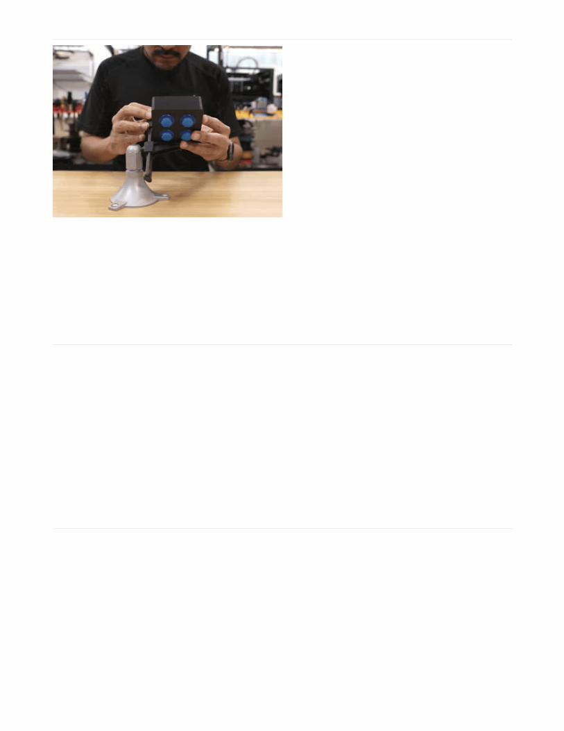
Close It UpNow it's time to close it all up! Make sure to orient the
Feather so the microUSB port is facing the cutout on the
side of the case. Bring the two pieces together and
make sure all of the wires are fitted inside the case. The
lip on the cover will snap into the case. Little nubs run
across the inner lining walls of the case will fit into
indentations on the lip of the case. They'll lock in place
when pressed together and you'll hear a satisfying
"clicking" sound.
© Adafruit Industries https://learn.adafruit.com/arcade-button-control-box Page 26 of 30

Make, Modify, Share
Congratulations! You've built your very own DIY USB HID keyboard. Did you modify it? What are you using it for? Let usknow! Tag @adafruit on your favorite social network and use hashtag #adafruit so we can find it! We love sharingproject makes from the community on our social channels.
If you have any technical questions, please post them up on our forums, we have a dedicated team of supportengineers who are there to help!
© Adafruit Industries https://learn.adafruit.com/arcade-button-control-box Page 27 of 30