Embed Size (px)
Citation preview
October 3, 2017
Arc Hydro Stormwater
Processing
i
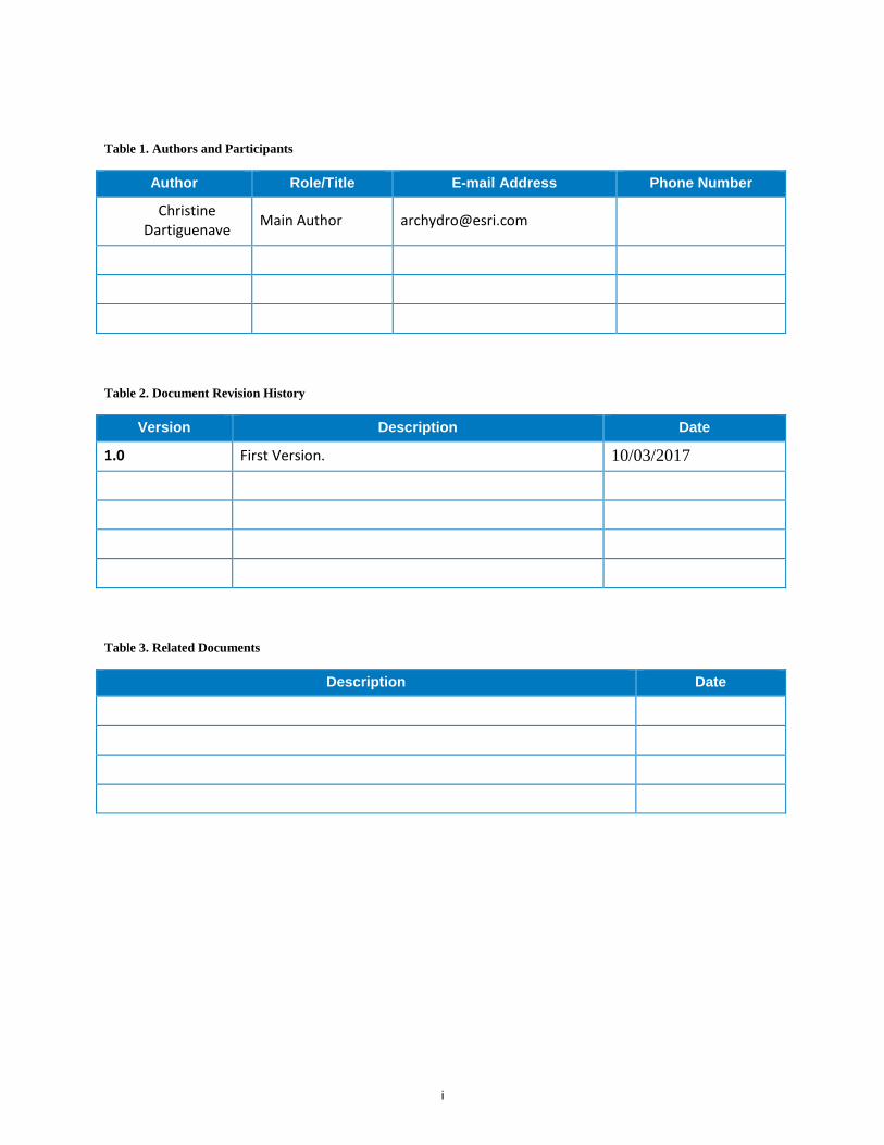
Table 1. Authors and Participants
Author Role/Title E-mail Address Phone Number
Christine Dartiguenave
Main Author [email protected]
Table 2. Document Revision History
Version Description Date
1.0 First Version. 10/03/2017
Table 3. Related Documents
Description Date
ii
Table of Contents
Section Title Page
1.0 Introduction ................................................................................................ 5
1.1 System Environment .......................................................................................... 5
1.2 Arc Hydro Version .............................................................................................. 5
1.3 Dataset ............................................................................................................... 5
1.4 Preprocessing Methodology ............................................................................... 5
2.0 Review Input Data ...................................................................................... 6
2.1 Data Projection ................................................................................................... 6
2.2 Digital Elevation Model ....................................................................................... 6
2.3 Identifying Stormwater Network Layers .............................................................. 9
2.4 Review Pipe Layer ........................................................................................... 10
2.5 Review Stream Layer ....................................................................................... 10
2.6 Review HydroJunction used as Inlet/Sinks ...................................................... 20
2.7 Fix network connectivity issues ........................................................................ 28
3.0 Create Input Draft Sink Polygon ............................................................. 32
3.1 Create Sink Polygons for defined HydroJunctions ........................................... 32
3.2 Add Sink Polygons associated to Stream ........................................................ 35
4.0 Processing Steps ..................................................................................... 37
4.1 Required Inputs ................................................................................................ 37
4.2 Outputs Supporting the Stormwater Delineation process ................................. 37
4.3 Summary and Processing Times ..................................................................... 38
4.4 Create Drainage Line Structures ...................................................................... 40
4.5 Create Sink Structures ..................................................................................... 41
4.6 DEM Reconditioning ........................................................................................ 43
4.7 Level DEM........................................................................................................ 44
4.8 Fill Sinks ........................................................................................................... 46
4.9 Flow Direction .................................................................................................. 47
4.10 Adjust Flow Direction in Sinks .......................................................................... 48
4.11 Adjust Flow Direction in Streams ..................................................................... 49
iii
4.12 Combine Stream Link and Sink Link ................................................................ 50
4.13 Catchment Grid Delineation ............................................................................. 51
4.14 Catchment Polygon Processing ....................................................................... 52
4.15 Adjoint Catchment Processing ......................................................................... 53
4.16 Sink Watershed Delineation ............................................................................. 54
4.17 Link Sink Watershed to HydroJunction ............................................................ 55
4.18 Create Stormwater Network ............................................................................. 56
4.19 Flow Accumulation ........................................................................................... 57
4.20 Create Snap Data ............................................................................................ 58
5.0 Stormwater Delineation ........................................................................... 59
6.0 Troubleshooting the Resulting Dataset ................................................. 60
List of Figures
Figure 1 - CSS Data and Stream Datasets ................................................................................. 5
Figure 2 – Define Projection Tool ............................................................................................... 7
Figure 3 - Define Z Coordinate System ...................................................................................... 7
Figure 4 - Projected Coordinate System..................................................................................... 8
Figure 5 - Sample Input Geometric Network .............................................................................. 9
Figure 6 - Open_Channel_NoNetwork Attributes Table .............................................................10
Figure 7 – Features with pseudo nodes ....................................................................................11
Figure 8 - Remove Stream Pseudo Nodes Tool ........................................................................11
Figure 9 - Remove Stream Pseudo Nodes Tool ........................................................................12
Figure 10 - Adding Stream entering the DEM ............................................................................13
Figure 11 – Adding Stream leaving the DEM ............................................................................14
Figure 12 – QC Roads Tool ......................................................................................................15
Figure 13 – QC Streams Tool ...................................................................................................16
Figure 15 - Stream QC Interface ...............................................................................................16
Figure 16 - Streams in same cell ...............................................................................................17
Figure 17 - Streams collapsed ..................................................................................................18
Figure 18 – Streams in same cells ............................................................................................18
Figure 19 - Streams moved to another cell ................................................................................19
Figure 20 - Overlapping streams ...............................................................................................19
Figure 21 - Missing HydroJunction at end of Terminal Stream ..................................................20
Figure 22 - Missing HydroJunction at end of Terminal Stream ..................................................21
iv
Figure 23 - Missing Catchments due to filled in stream .............................................................21
Figure 24 - Create Sinks for Line Structure tool .........................................................................22
Figure 25 - Identifying Disconnected Network Features ............................................................29
Figure 26 - Line not connecting to end point .............................................................................30
Figure 27. Identifying Disconnected Features ...........................................................................30
Figure 28. Selecting Network Features to Connect ...................................................................30
Figure 29 – Connect Tool ..........................................................................................................31
Figure 30. Buffer Tool ...............................................................................................................32
Figure 31 - Create Sink Structures Tool ....................................................................................41
Figure 32 - Create Sink Structures Interface .............................................................................41
Figure 33 - Create Drainage Line Structures .............................................................................40
Figure 34 - Create Drainage Line Structures Interface ..............................................................40
Figure 35 - DEM Reconditioning Tool .......................................................................................43
Figure 36 - DEM Reconditioning Interface .................................................................................43
Figure 37 - Leveling Sensitivity .................................................................................................44
Figure 38 – Level DEM Tool ......................................................................................................45
Figure 39 – Level DEM Interface ...............................................................................................45
Figure 40 - Fill Sinks Tool .........................................................................................................46
Figure 41 - Flow Direction Interface ..........................................................................................47
Figure 42 - Adjust Flow Direction in Sinks Interface ..................................................................48
Figure 43 - Adjust Flow Direction in Streams ............................................................................49
Figure 44 - Combine Stream Link and Sink Link Interface .........................................................50
Figure 45 – Catchment Grid Delineation Interface .....................................................................51
Figure 46 - Catchment Polygon Processing ..............................................................................52
Figure 47 - Adjoint Catchment Processing Interface .................................................................53
Figure 48 - Example of missing Hydrojunction at end of Stream ...............................................70
List of Tables
Table 1. Authors and Participants ................................................................................................ i
Table 2. Document Revision History ............................................................................................ i
Table 3. Related Documents ........................................................................................................ i
Table 4. Processing Steps Table...............................................................................................38
Arc Hydro Stormwater Processing 5 10/2017
1.0 Introduction
This document describes how to prepare the data required to support the Arc Hydro stormwater
delineation tool.
1.1 System Environment
This workflow requires ArcGIS for Desktop 10.3.1 or greater with the Spatial Analyst Extension.
1.2 Arc Hydro Version
All processing may be performed using the versions of the Arc Hydro tools released after August
2017. Ensure you are using the Arc Hydro Tools Python toolbox, not the old Arc Hydro Tools,
and not the Arc Hydro Tools menu bar:
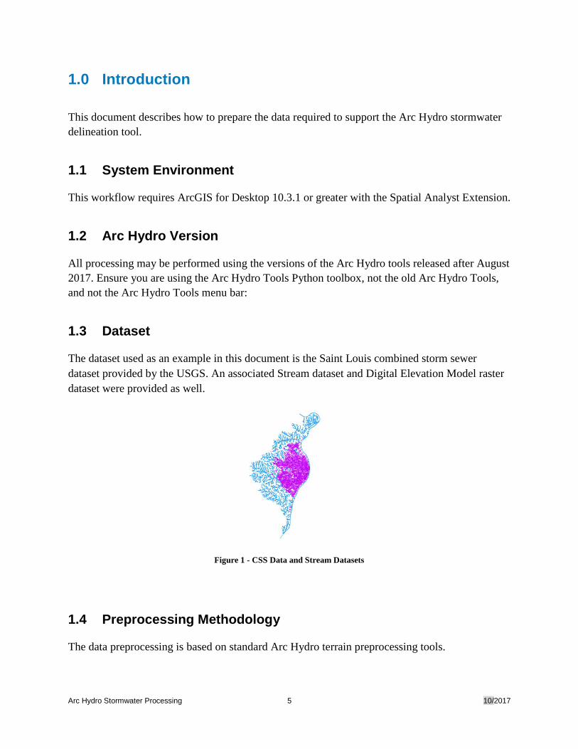
1.3 Dataset
The dataset used as an example in this document is the Saint Louis combined storm sewer
dataset provided by the USGS. An associated Stream dataset and Digital Elevation Model raster
dataset were provided as well.
Figure 1 - CSS Data and Stream Datasets
1.4 Preprocessing Methodology
The data preprocessing is based on standard Arc Hydro terrain preprocessing tools.
Arc Hydro Stormwater Processing 6 10/2017
1. All vector layers in the dataset must have HydroIDs assigned. The tools used in this
document require geodatabase feature class layers as input and output data layers.
2. If errors are encountered, it is advised that users use a new ArcMap document to continue
tasks.
3. Ensure that Target Locations are set in all new map documents.
2.0 Review Input Data
• Stormwater Network
• Stream
• DEM
2.1 Data Projection
The same projection must be used for raster and vector data. Projection must use a projected
coordinate system that makes sense to support further analyses (area/length).
2.2 Digital Elevation Model
The DEM should be integer to speed up processing time.
Check units. If the DEM is in meters, convert it to centimeters. You can use the following map
algebra expression in the Raster Calculator: Int( ( "floating_point_DEM" * 100 ) + .5 )
The input dem_raw has values ranging from 22511 to 5899. The linear unit is meters, which
means the elevation are in centimeters.
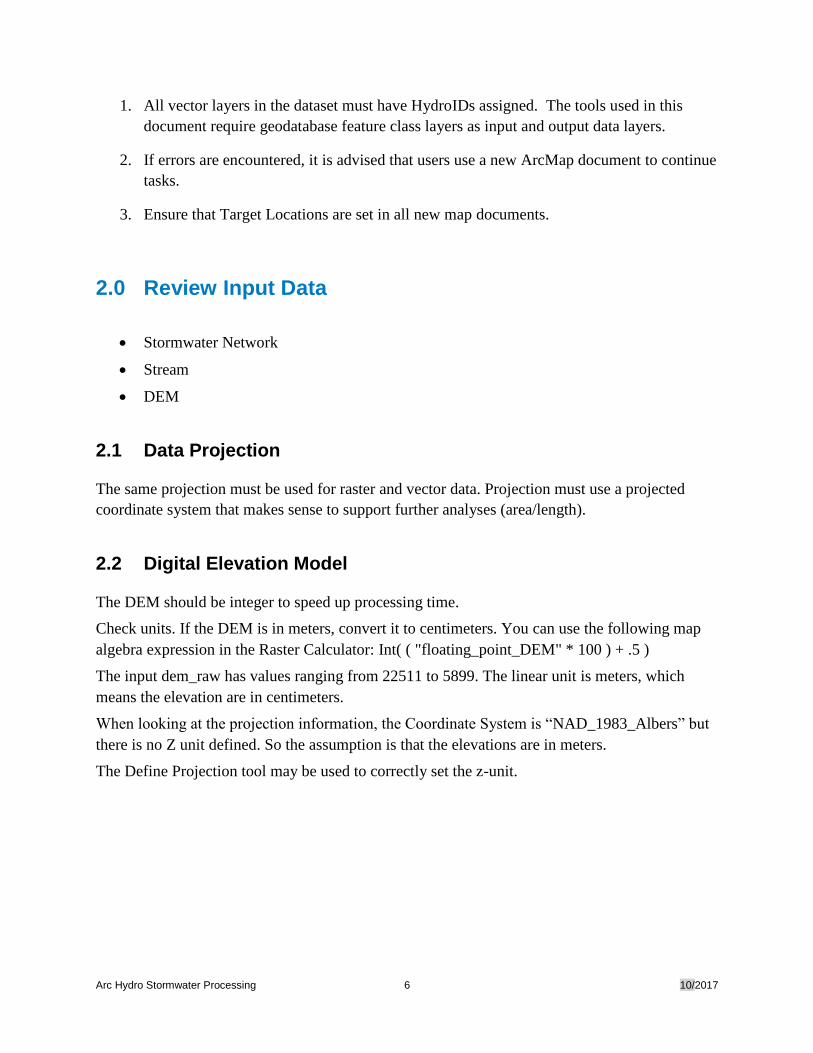
When looking at the projection information, the Coordinate System is “NAD_1983_Albers” but
there is no Z unit defined. So the assumption is that the elevations are in meters.
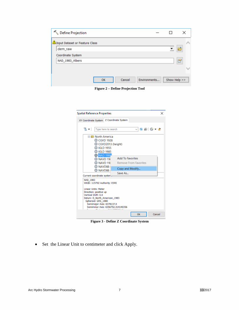
The Define Projection tool may be used to correctly set the z-unit.
Arc Hydro Stormwater Processing 7 10/2017
Figure 2 – Define Projection Tool
Figure 3 - Define Z Coordinate System
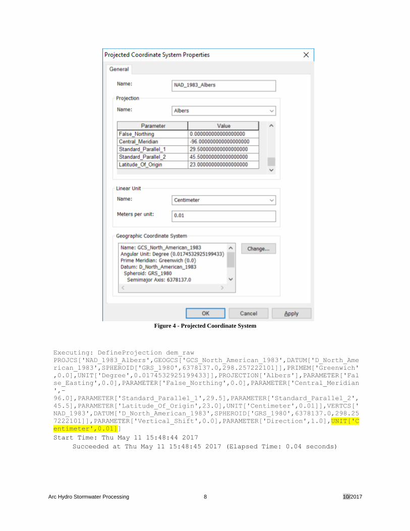
• Set the Linear Unit to centimeter and click Apply.
Arc Hydro Stormwater Processing 8 10/2017
Figure 4 - Projected Coordinate System
Executing: DefineProjection dem_raw
PROJCS['NAD_1983_Albers',GEOGCS['GCS_North_American_1983',DATUM['D_North_Ame
rican_1983',SPHEROID['GRS_1980',6378137.0,298.257222101]],PRIMEM['Greenwich'
,0.0],UNIT['Degree',0.0174532925199433]],PROJECTION['Albers'],PARAMETER['Fal
se_Easting',0.0],PARAMETER['False_Northing',0.0],PARAMETER['Central_Meridian
',-
96.0],PARAMETER['Standard_Parallel_1',29.5],PARAMETER['Standard_Parallel_2',
45.5],PARAMETER['Latitude_Of_Origin',23.0],UNIT['Centimeter',0.01]],VERTCS['
NAD_1983',DATUM['D_North_American_1983',SPHEROID['GRS_1980',6378137.0,298.25
7222101]],PARAMETER['Vertical_Shift',0.0],PARAMETER['Direction',1.0],UNIT['C
entimeter',0.01]]
Start Time: Thu May 11 15:48:44 2017
Succeeded at Thu May 11 15:48:45 2017 (Elapsed Time: 0.04 seconds)
Arc Hydro Stormwater Processing 9 10/2017
2.3 Identifying Stormwater Network Layers
2.3.1 Defining Layers Roles
The requirements for the network that will support the stormwater delineation process are as
follows:
• Pipe line layer
• Stream line layer,
• HydroJunction: point location where the water may enter the closed pipe system via an
inlet or seep into the ground via a sink. These HydroJunctions will be related to an
associated SinkWatershed.
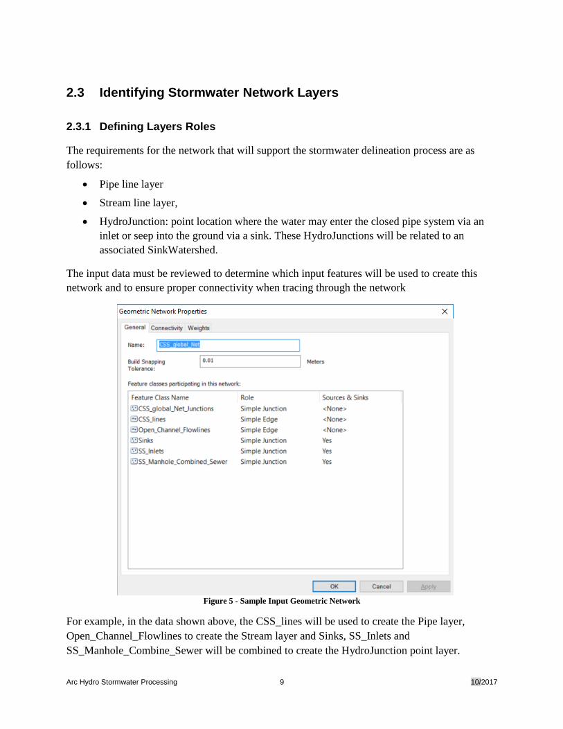
The input data must be reviewed to determine which input features will be used to create this
network and to ensure proper connectivity when tracing through the network
Figure 5 - Sample Input Geometric Network
For example, in the data shown above, the CSS_lines will be used to create the Pipe layer,
Open_Channel_Flowlines to create the Stream layer and Sinks, SS_Inlets and
SS_Manhole_Combine_Sewer will be combined to create the HydroJunction point layer.
Arc Hydro Stormwater Processing 10 10/2017
2.4 Review Pipe Layer
Surface water enter the Pipe via a HydroJunction (Inlet).
A pipe may connect to another pipe or stream feature without requiring a HydroJunction (Inlet or
Sink) at its end.
Pipe may end in a HydroJunction (Sink).
2.5 Review Stream Layer
If your input data is part of an existing network export the layer so that it does not belong to the
network.
For example, in the CSS network, the Open_Channel network edge layer was exported to the
layer Open_Channel_NoNetwork.
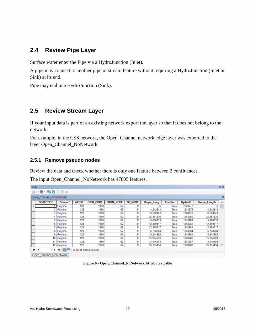
2.5.1 Remove pseudo nodes
Review the data and check whether there is only one feature between 2 confluences.
The input Open_Channel_NoNetwork has 47805 features.
Figure 6 - Open_Channel_NoNetwork Attributes Table
Arc Hydro Stormwater Processing 11 10/2017
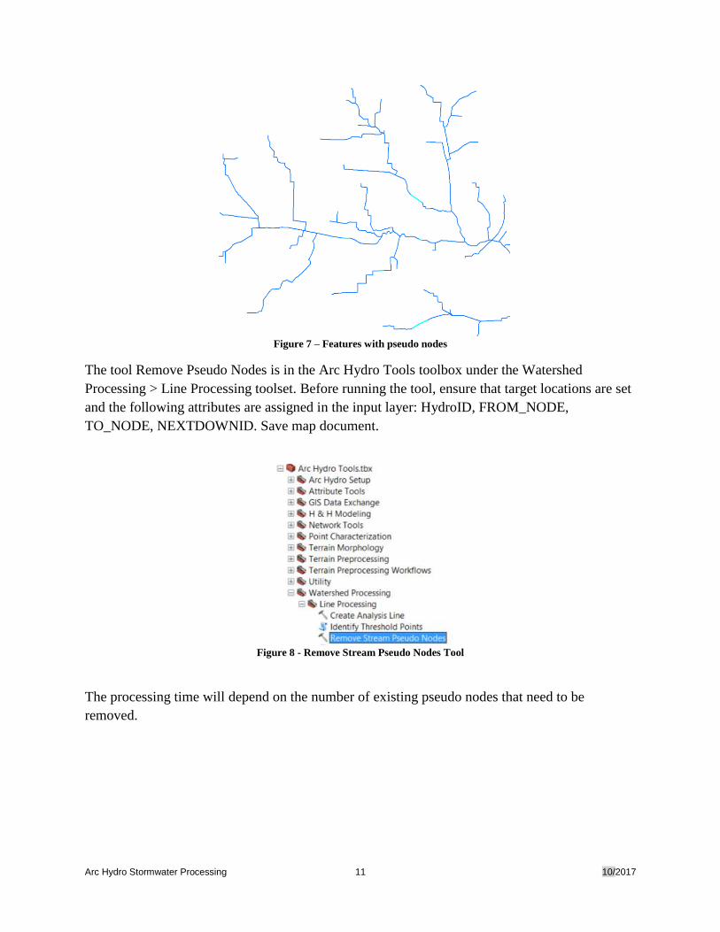
Figure 7 – Features with pseudo nodes
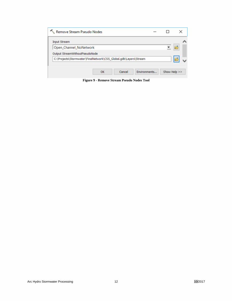
The tool Remove Pseudo Nodes is in the Arc Hydro Tools toolbox under the Watershed
Processing > Line Processing toolset. Before running the tool, ensure that target locations are set
and the following attributes are assigned in the input layer: HydroID, FROM_NODE,
TO_NODE, NEXTDOWNID. Save map document.
Figure 8 - Remove Stream Pseudo Nodes Tool
The processing time will depend on the number of existing pseudo nodes that need to be
removed.
Arc Hydro Stormwater Processing 12 10/2017
Figure 9 - Remove Stream Pseudo Nodes Tool
Arc Hydro Stormwater Processing 13 10/2017
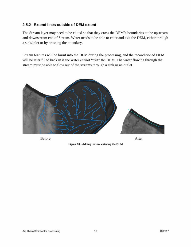
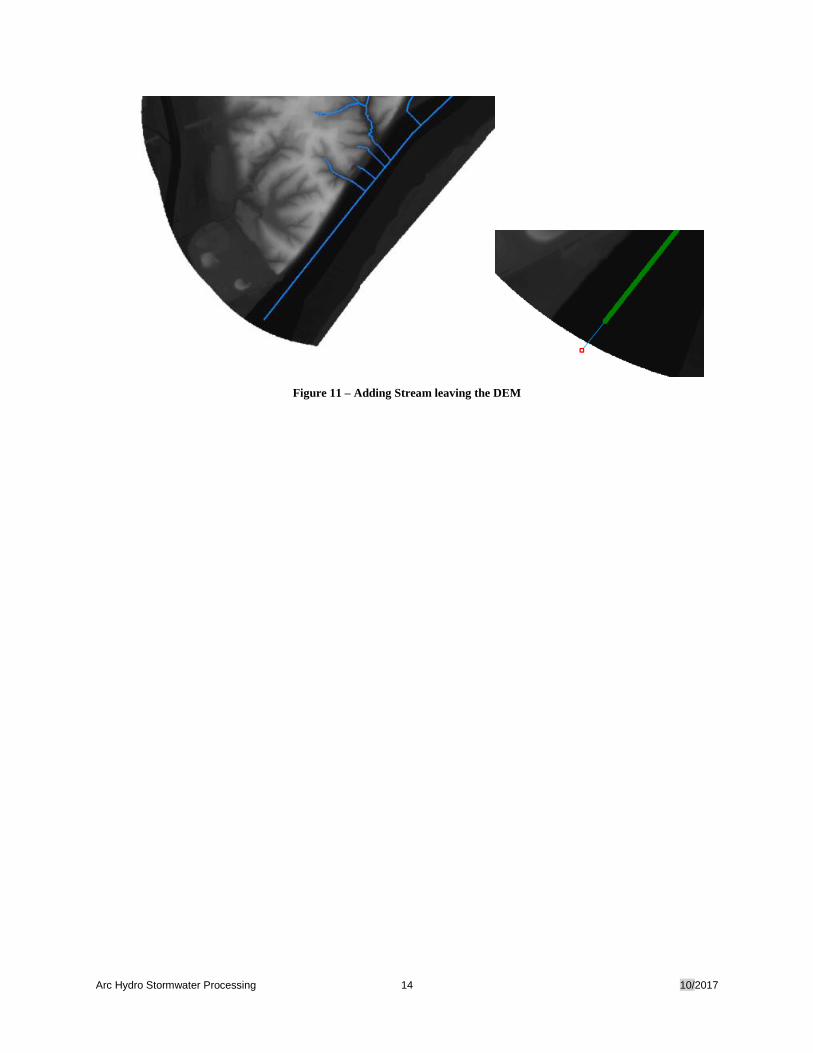
2.5.2 Extend lines outside of DEM extent
The Stream layer may need to be edited so that they cross the DEM’s boundaries at the upstream
and downstream end of Stream. Water needs to be able to enter and exit the DEM, either through
a sink/inlet or by crossing the boundary.
Stream features will be burnt into the DEM during the processing, and the reconditioned DEM
will be later filled back in if the water cannot “exit” the DEM. The water flowing through the
stream must be able to flow out of the streams through a sink or an outlet.
Before After
Figure 10 - Adding Stream entering the DEM
Arc Hydro Stormwater Processing 14 10/2017
Figure 11 – Adding Stream leaving the DEM
Arc Hydro Stormwater Processing 15 10/2017
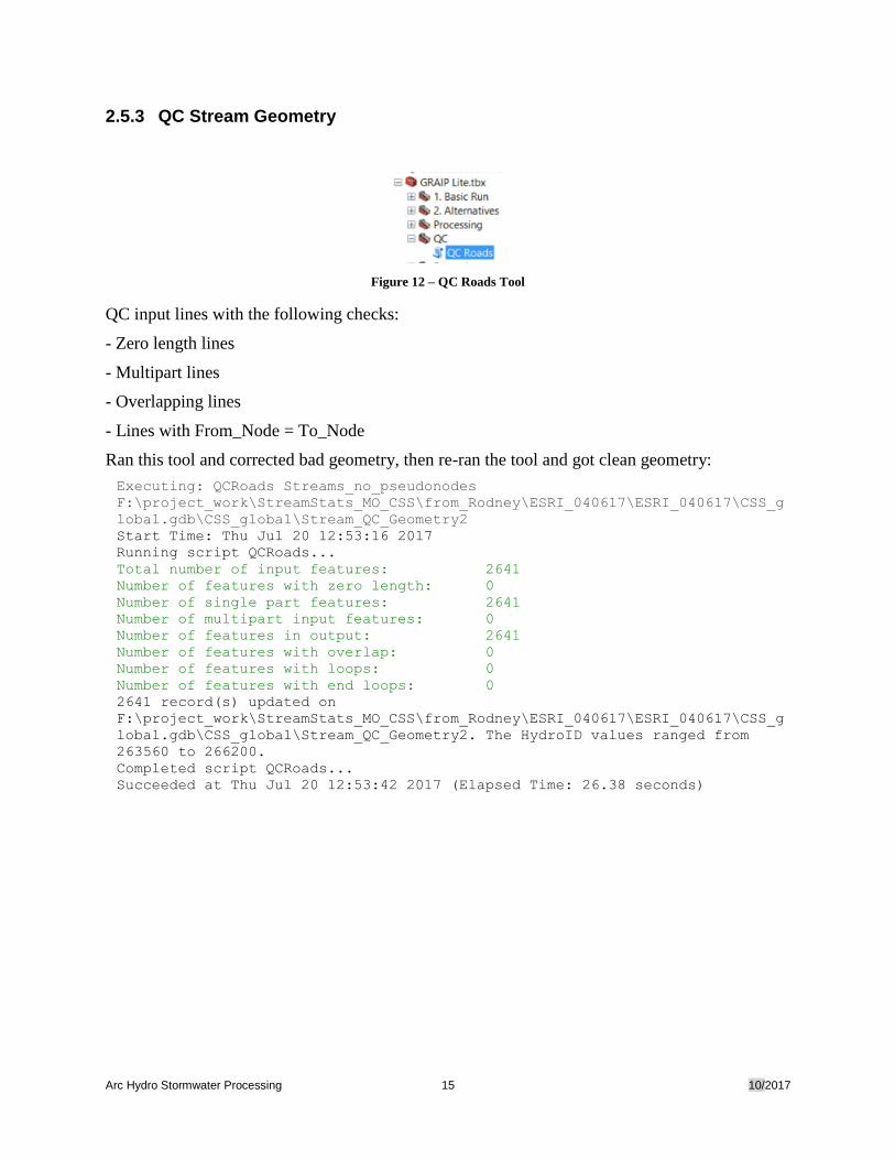
2.5.3 QC Stream Geometry
Figure 12 – QC Roads Tool
QC input lines with the following checks:
- Zero length lines
- Multipart lines
- Overlapping lines
- Lines with From_Node = To_Node
Ran this tool and corrected bad geometry, then re-ran the tool and got clean geometry:
Executing: QCRoads Streams_no_pseudonodes
F:\project_work\StreamStats_MO_CSS\from_Rodney\ESRI_040617\ESRI_040617\CSS_g
lobal.gdb\CSS_global\Stream_QC_Geometry2
Start Time: Thu Jul 20 12:53:16 2017
Running script QCRoads...
Total number of input features: 2641
Number of features with zero length: 0
Number of single part features: 2641
Number of multipart input features: 0
Number of features in output: 2641
Number of features with overlap: 0
Number of features with loops: 0
Number of features with end loops: 0
2641 record(s) updated on
F:\project_work\StreamStats_MO_CSS\from_Rodney\ESRI_040617\ESRI_040617\CSS_g
lobal.gdb\CSS_global\Stream_QC_Geometry2. The HydroID values ranged from
263560 to 266200.
Completed script QCRoads...
Succeeded at Thu Jul 20 12:53:42 2017 (Elapsed Time: 26.38 seconds)
Arc Hydro Stormwater Processing 16 10/2017
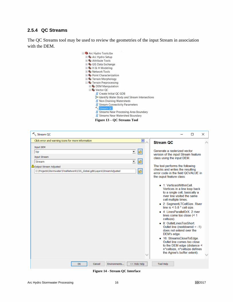
2.5.4 QC Streams
The QC Streams tool may be used to review the geometries of the input Stream in association
with the DEM.
Figure 13 – QC Streams Tool
Figure 14 - Stream QC Interface
Arc Hydro Stormwater Processing 17 10/2017
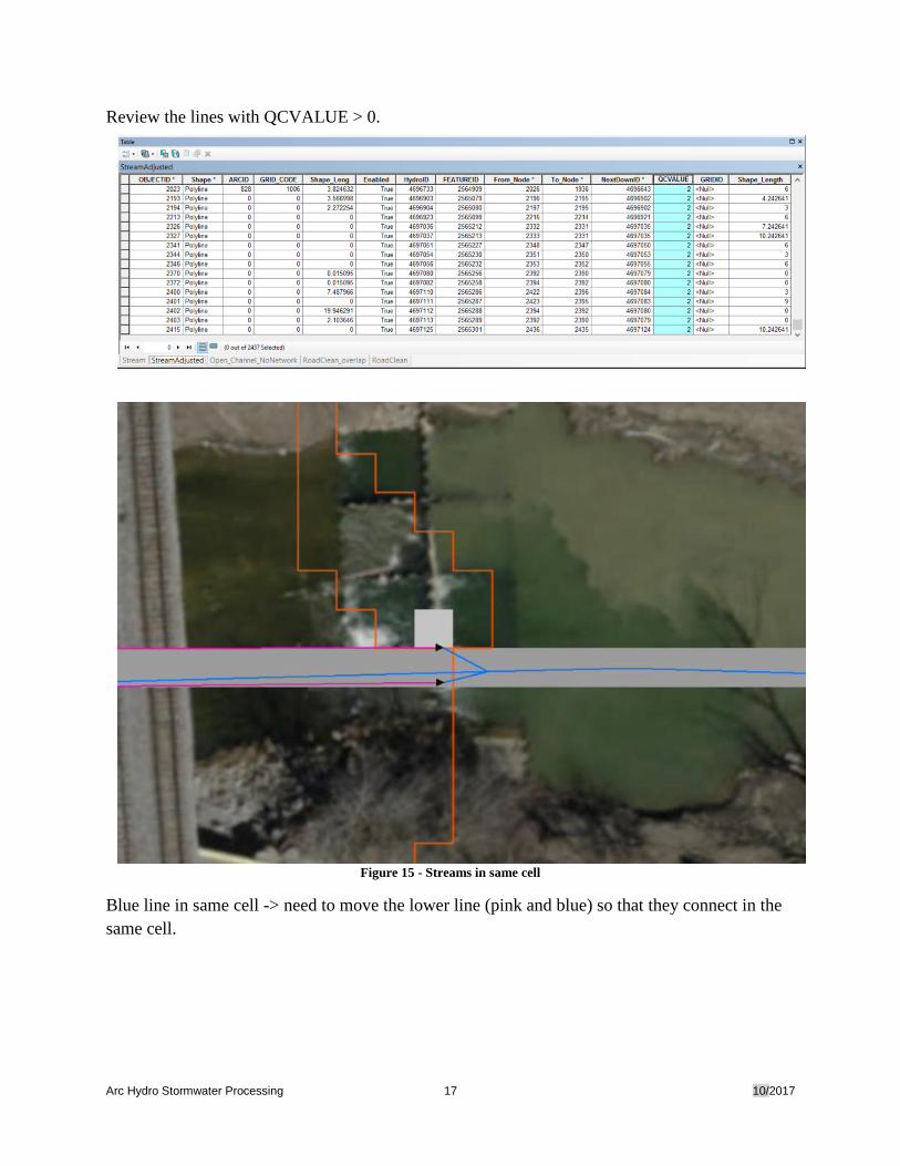
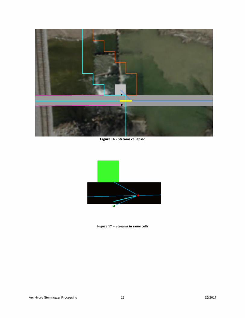
Review the lines with QCVALUE > 0.
Figure 15 - Streams in same cell
Blue line in same cell -> need to move the lower line (pink and blue) so that they connect in the
same cell.
Arc Hydro Stormwater Processing 18 10/2017
Figure 16 - Streams collapsed
Figure 17 – Streams in same cells
Arc Hydro Stormwater Processing 19 10/2017
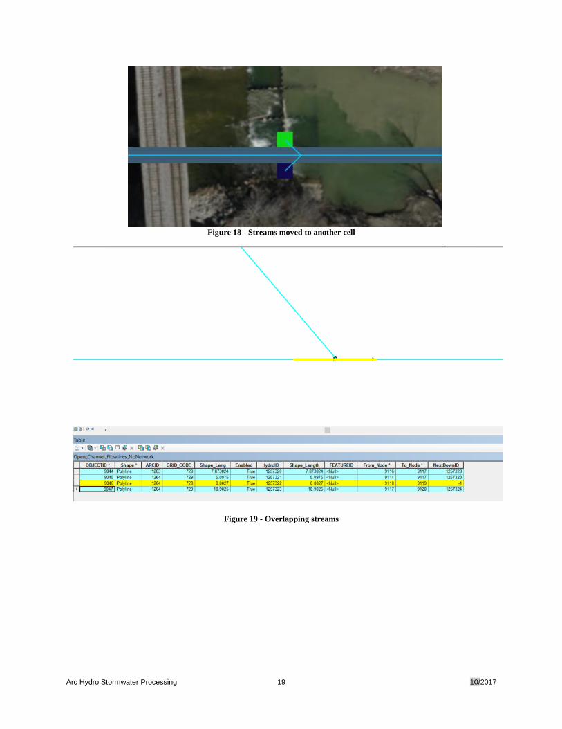
Figure 18 - Streams moved to another cell
Figure 19 - Overlapping streams
Arc Hydro Stormwater Processing 20 10/2017
2.6 Review HydroJunction used as Inlet/Sinks
2.6.1 Add Pipe Inlet/Sink HydroJunctions
All features identified as potential Inlet/Sink points need to be combined into a new
HydroJunction point feature class. The various input layers may be combined using the Merge
geoprocessing tool.
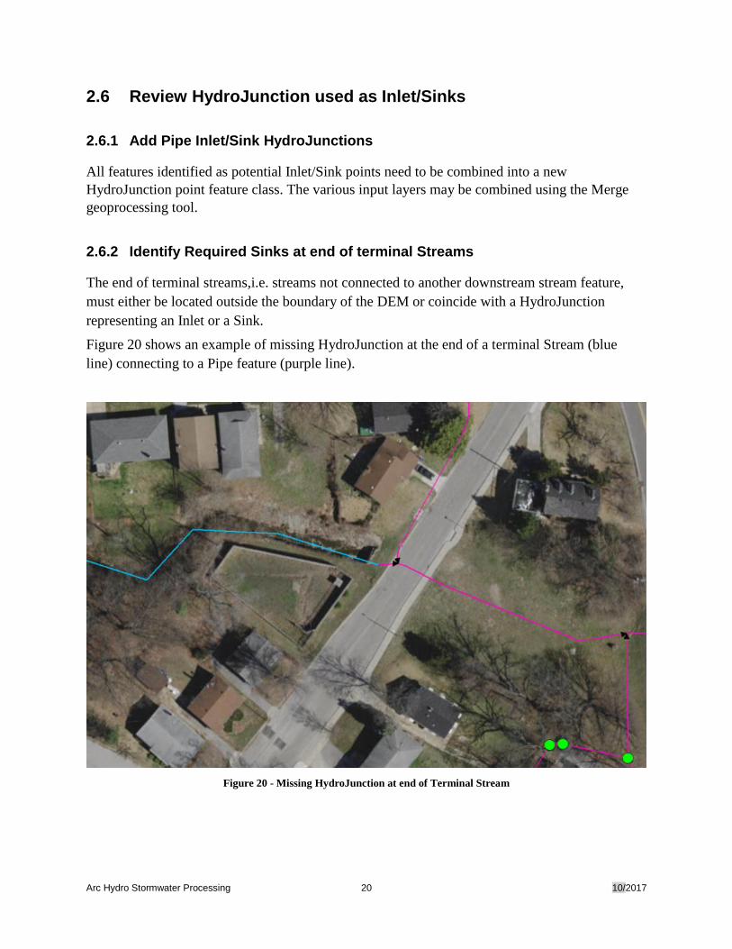
2.6.2 Identify Required Sinks at end of terminal Streams
The end of terminal streams,i.e. streams not connected to another downstream stream feature,
must either be located outside the boundary of the DEM or coincide with a HydroJunction
representing an Inlet or a Sink.
Figure 20 shows an example of missing HydroJunction at the end of a terminal Stream (blue
line) connecting to a Pipe feature (purple line).
Figure 20 - Missing HydroJunction at end of Terminal Stream
Arc Hydro Stormwater Processing 21 10/2017
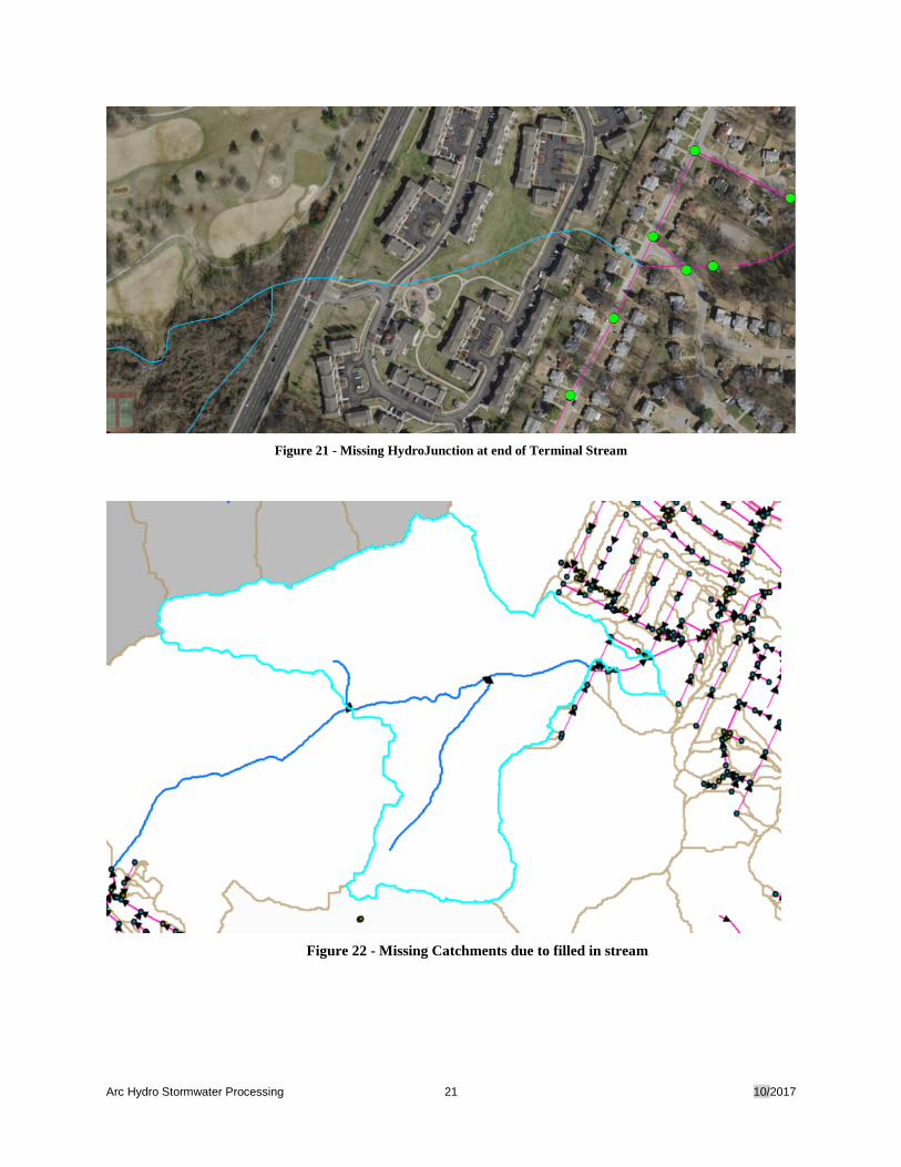
Figure 21 - Missing HydroJunction at end of Terminal Stream
Figure 22 - Missing Catchments due to filled in stream
Arc Hydro Stormwater Processing 22 10/2017
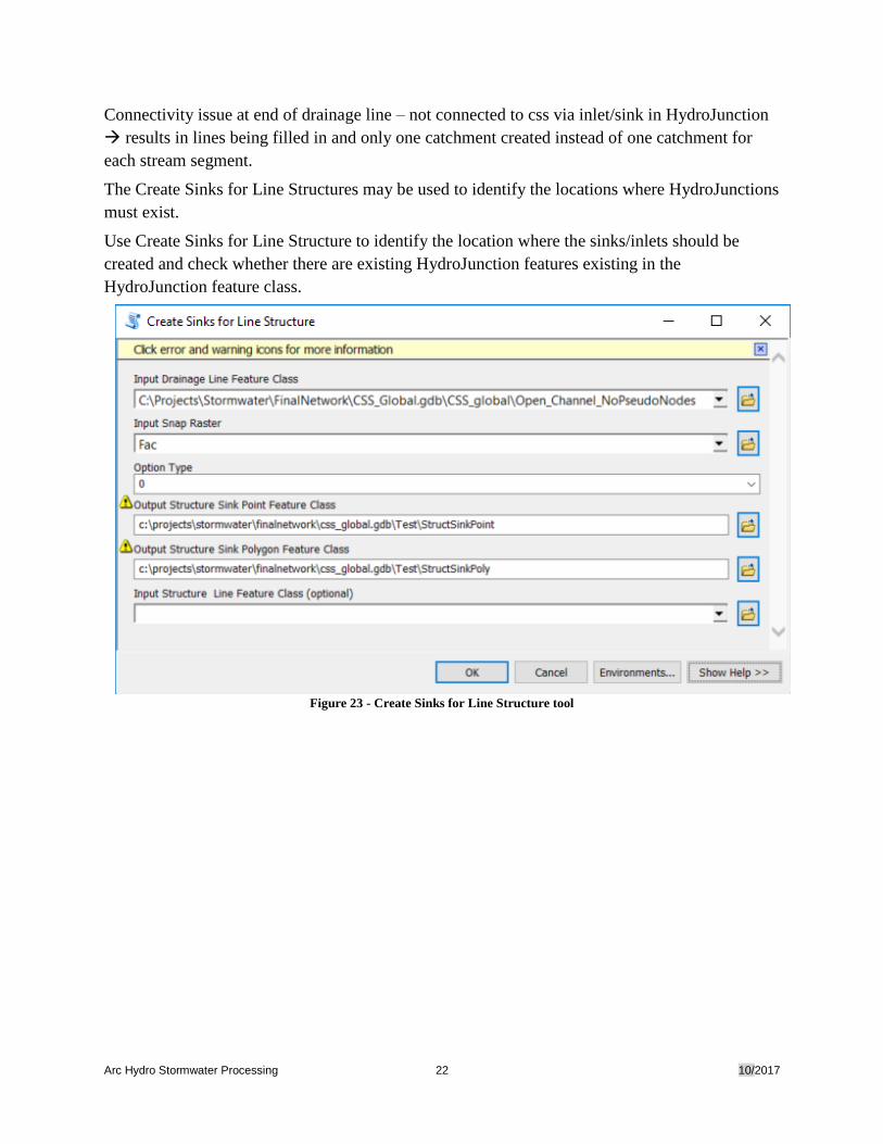
Connectivity issue at end of drainage line – not connected to css via inlet/sink in HydroJunction
results in lines being filled in and only one catchment created instead of one catchment for
each stream segment.
The Create Sinks for Line Structures may be used to identify the locations where HydroJunctions
must exist.
Use Create Sinks for Line Structure to identify the location where the sinks/inlets should be
created and check whether there are existing HydroJunction features existing in the
HydroJunction feature class.
Figure 23 - Create Sinks for Line Structure tool
Arc Hydro Stormwater Processing 23 10/2017
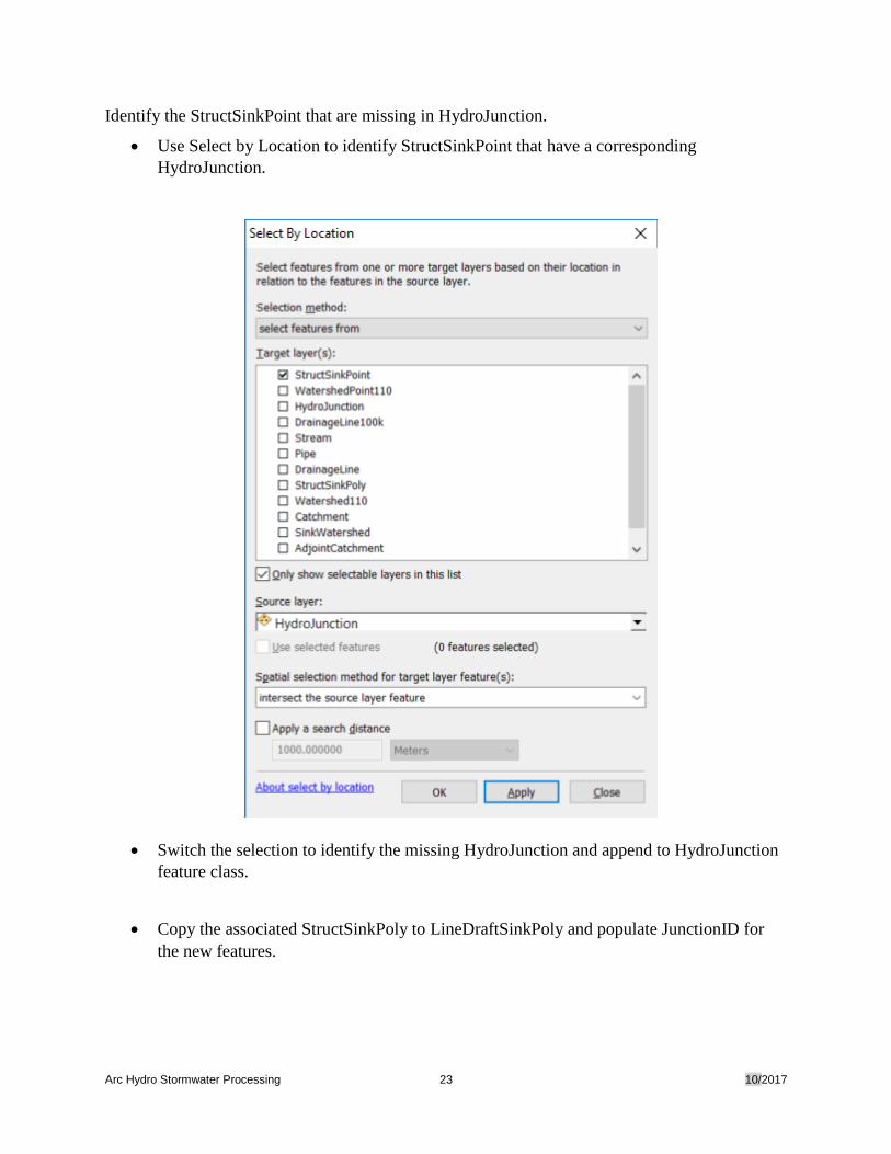
Identify the StructSinkPoint that are missing in HydroJunction.
• Use Select by Location to identify StructSinkPoint that have a corresponding
HydroJunction.
• Switch the selection to identify the missing HydroJunction and append to HydroJunction
feature class.
• Copy the associated StructSinkPoly to LineDraftSinkPoly and populate JunctionID for
the new features.
Arc Hydro Stormwater Processing 24 10/2017
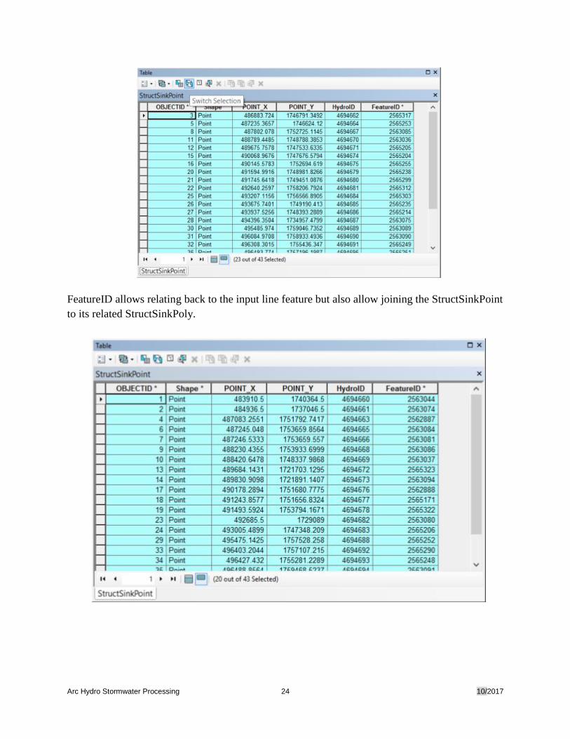
FeatureID allows relating back to the input line feature but also allow joining the StructSinkPoint
to its related StructSinkPoly.
Arc Hydro Stormwater Processing 25 10/2017
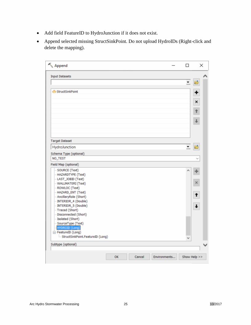
• Add field FeatureID to HydroJunction if it does not exist.
• Append selected missing StructSinkPoint. Do not upload HydroIDs (Right-click and
delete the mapping).
Arc Hydro Stormwater Processing 26 10/2017
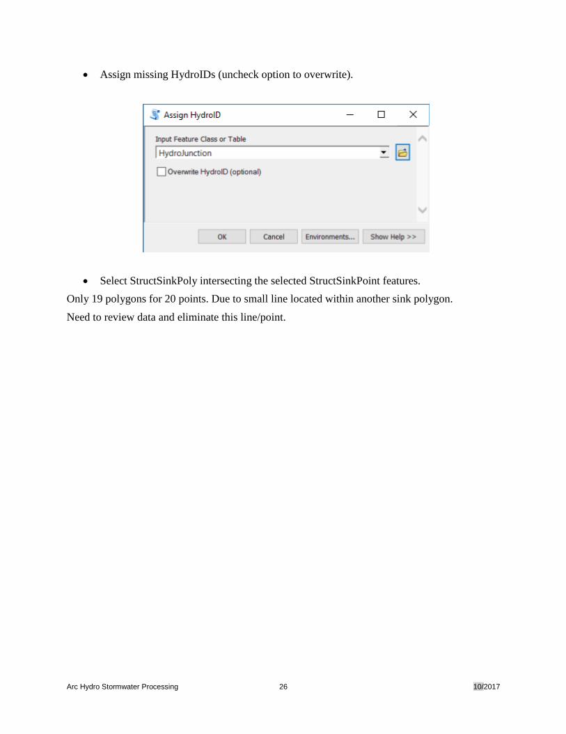
• Assign missing HydroIDs (uncheck option to overwrite).
• Select StructSinkPoly intersecting the selected StructSinkPoint features.
Only 19 polygons for 20 points. Due to small line located within another sink polygon.
Need to review data and eliminate this line/point.
Arc Hydro Stormwater Processing 27 10/2017
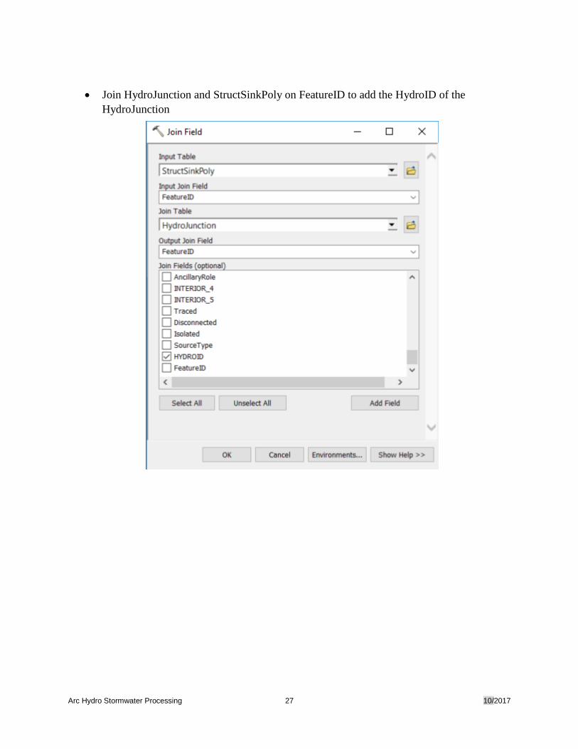
• Join HydroJunction and StructSinkPoly on FeatureID to add the HydroID of the
HydroJunction
Arc Hydro Stormwater Processing 28 10/2017
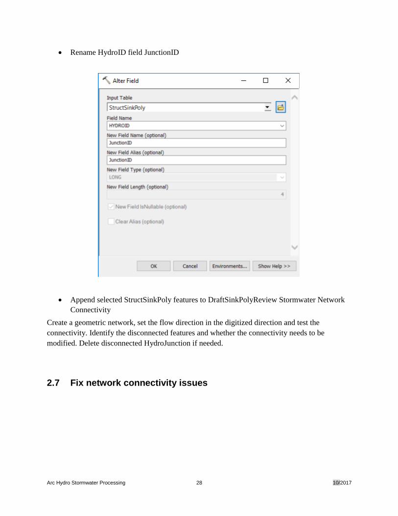
• Rename HydroID field JunctionID
• Append selected StructSinkPoly features to DraftSinkPolyReview Stormwater Network
Connectivity
Create a geometric network, set the flow direction in the digitized direction and test the
connectivity. Identify the disconnected features and whether the connectivity needs to be
modified. Delete disconnected HydroJunction if needed.
2.7 Fix network connectivity issues
Arc Hydro Stormwater Processing 29 10/2017
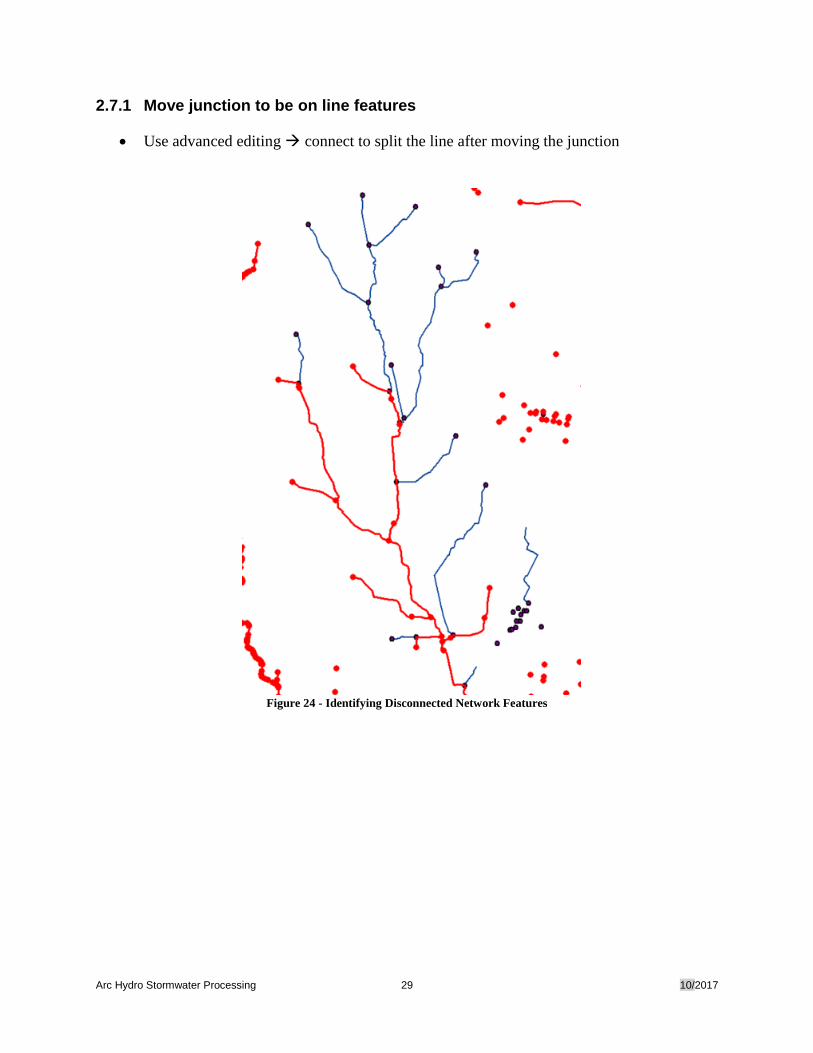
2.7.1 Move junction to be on line features
• Use advanced editing connect to split the line after moving the junction
Figure 24 - Identifying Disconnected Network Features
Arc Hydro Stormwater Processing 30 10/2017
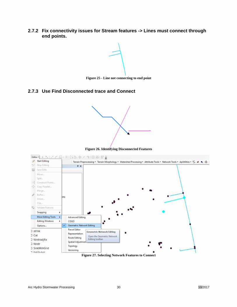
2.7.2 Fix connectivity issues for Stream features -> Lines must connect through end points.
Figure 25 - Line not connecting to end point
2.7.3 Use Find Disconnected trace and Connect
Figure 26. Identifying Disconnected Features
Figure 27. Selecting Network Features to Connect
Arc Hydro Stormwater Processing 31 10/2017
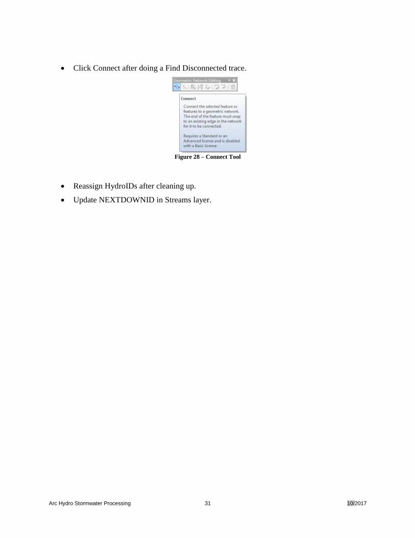
• Click Connect after doing a Find Disconnected trace.
Figure 28 – Connect Tool
• Reassign HydroIDs after cleaning up.
• Update NEXTDOWNID in Streams layer.
Arc Hydro Stormwater Processing 32 10/2017
3.0 Create Input Draft Sink Polygon
3.1 Create Sink Polygons for defined HydroJunctions
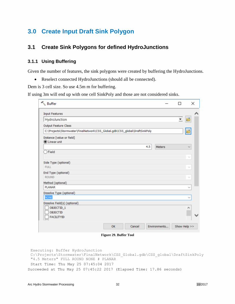
3.1.1 Using Buffering
Given the number of features, the sink polygons were created by buffering the HydroJunctions.
• Reselect connected HydroJunctions (should all be connected).
Dem is 3 cell size. So use 4.5m m for buffering.
If using 3m will end up with one cell SinkPoly and those are not considered sinks.
Figure 29. Buffer Tool
Executing: Buffer HydroJunction
C:\Projects\Stormwater\FinalNetwork\CSS_Global.gdb\CSS_global\DraftSinkPoly
"4.5 Meters" FULL ROUND NONE # PLANAR
Start Time: Thu May 25 07:45:04 2017
Succeeded at Thu May 25 07:45:22 2017 (Elapsed Time: 17.86 seconds)
Arc Hydro Stormwater Processing 33 10/2017
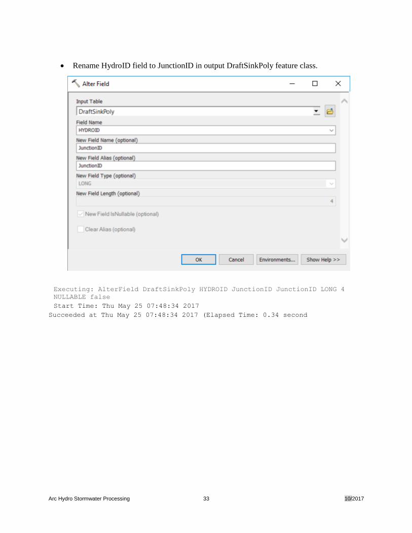
• Rename HydroID field to JunctionID in output DraftSinkPoly feature class.
Executing: AlterField DraftSinkPoly HYDROID JunctionID JunctionID LONG 4
NULLABLE false
Start Time: Thu May 25 07:48:34 2017
Succeeded at Thu May 25 07:48:34 2017 (Elapsed Time: 0.34 second
Arc Hydro Stormwater Processing 34 10/2017
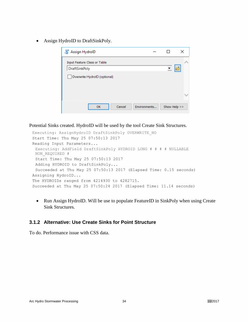
• Assign HydroID to DraftSinkPoly.
Potential Sinks created. HydroID will be used by the tool Create Sink Structures.
Executing: AssignHydroID DraftSinkPoly OVERWRITE_NO
Start Time: Thu May 25 07:50:13 2017
Reading Input Parameters...
Executing: AddField DraftSinkPoly HYDROID LONG # # # # NULLABLE
NON_REQUIRED #
Start Time: Thu May 25 07:50:13 2017
Adding HYDROID to DraftSinkPoly...
Succeeded at Thu May 25 07:50:13 2017 (Elapsed Time: 0.15 seconds)
Assigning HydroID...
The HYDROIDs ranged from 4214930 to 4282715.
Succeeded at Thu May 25 07:50:24 2017 (Elapsed Time: 11.14 seconds)
• Run Assign HydroID. Will be use to populate FeatureID in SinkPoly when using Create
Sink Structures.
3.1.2 Alternative: Use Create Sinks for Point Structure
To do. Performance issue with CSS data.
Arc Hydro Stormwater Processing 35 10/2017
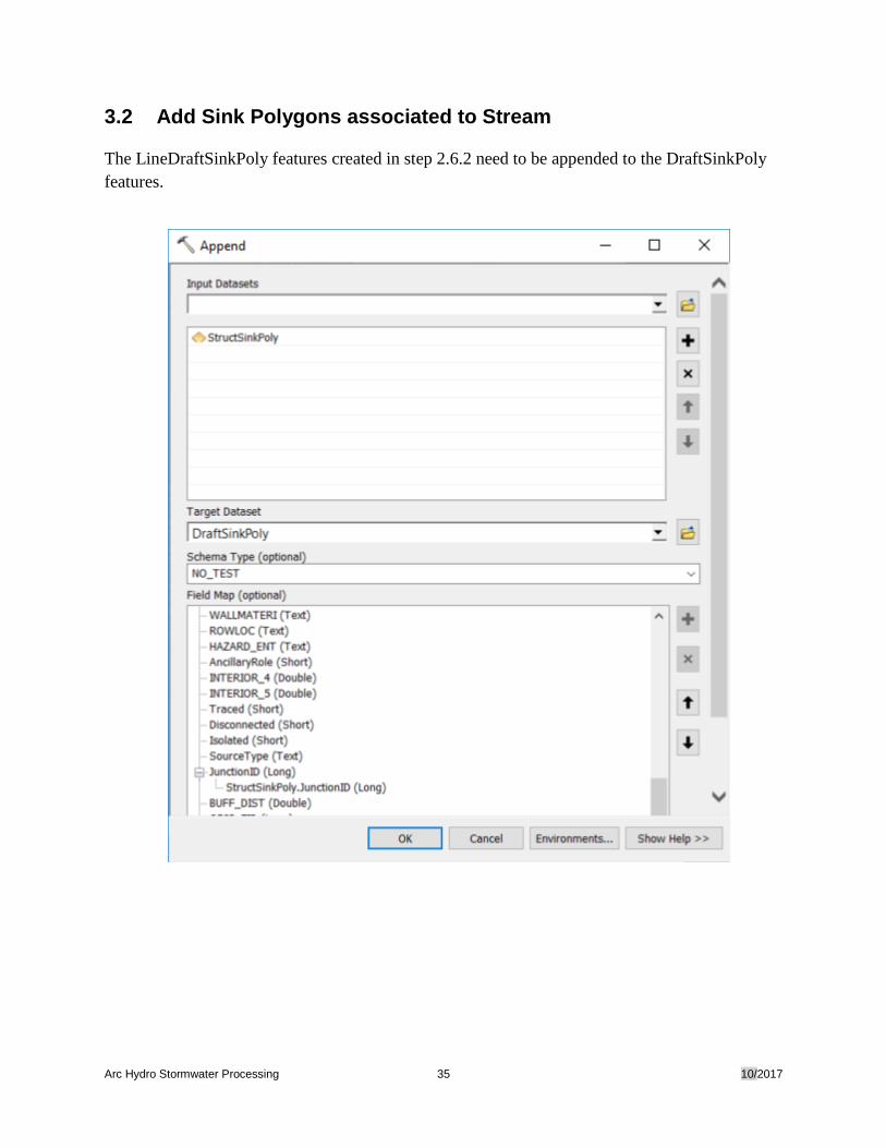
3.2 Add Sink Polygons associated to Stream
The LineDraftSinkPoly features created in step 2.6.2 need to be appended to the DraftSinkPoly
features.
Arc Hydro Stormwater Processing 36 10/2017
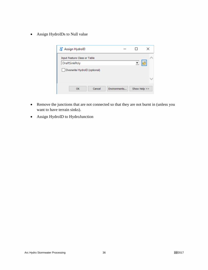
• Assign HydroIDs to Null value
• Remove the junctions that are not connected so that they are not burnt in (unless you
want to have terrain sinks).
• Assign HydroID to HydroJunction
Arc Hydro Stormwater Processing 37 10/2017
4.0 Processing Steps
4.1 Required Inputs
The required inputs are the following:
• Pipe line feature class
• Stream line feature class
• DraftSinkPoly polygon feature class
• HydroJunction polygon feature class
• DEM
4.2 Outputs Supporting the Stormwater Delineation process
The following outputs will support the stormwater delineation process:
• Flow Direction
• Stream Link
• Snap Stream Raster
• Catchment
• Adjoint Catchment
• Pipe
• Stream
• Sink Watershed
• HydroJunction
Arc Hydro Stormwater Processing 38 10/2017
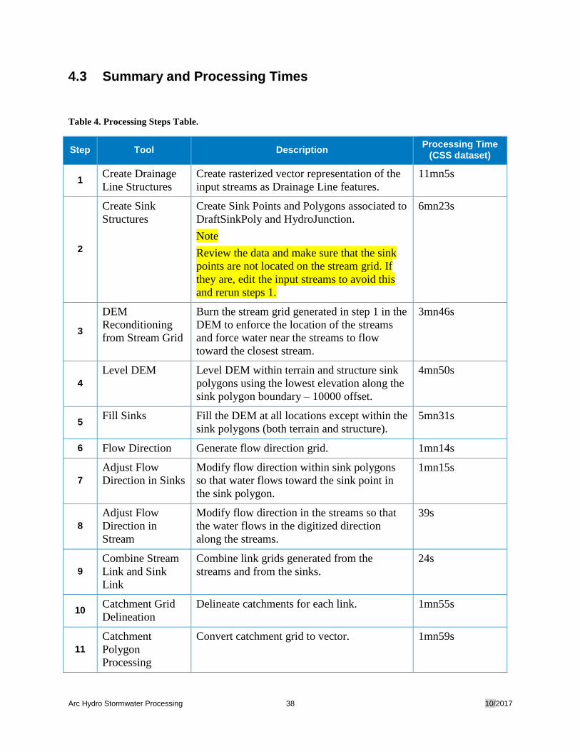
4.3 Summary and Processing Times
Table 4. Processing Steps Table.
Step Tool Description Processing Time
(CSS dataset)
1 Create Drainage
Line Structures
Create rasterized vector representation of the
input streams as Drainage Line features.
11mn5s
2
Create Sink
Structures
Create Sink Points and Polygons associated to
DraftSinkPoly and HydroJunction.
Note
Review the data and make sure that the sink
points are not located on the stream grid. If
they are, edit the input streams to avoid this
and rerun steps 1.
6mn23s
3
DEM
Reconditioning
from Stream Grid
Burn the stream grid generated in step 1 in the
DEM to enforce the location of the streams
and force water near the streams to flow
toward the closest stream.
3mn46s
4
Level DEM Level DEM within terrain and structure sink
polygons using the lowest elevation along the
sink polygon boundary – 10000 offset.
4mn50s
5 Fill Sinks Fill the DEM at all locations except within the
sink polygons (both terrain and structure).
5mn31s
6 Flow Direction Generate flow direction grid. 1mn14s
7
Adjust Flow
Direction in Sinks
Modify flow direction within sink polygons
so that water flows toward the sink point in
the sink polygon.
1mn15s
8
Adjust Flow
Direction in
Stream
Modify flow direction in the streams so that
the water flows in the digitized direction
along the streams.
39s
9
Combine Stream
Link and Sink
Link
Combine link grids generated from the
streams and from the sinks.
24s
10 Catchment Grid
Delineation
Delineate catchments for each link. 1mn55s
11
Catchment
Polygon
Processing
Convert catchment grid to vector. 1mn59s
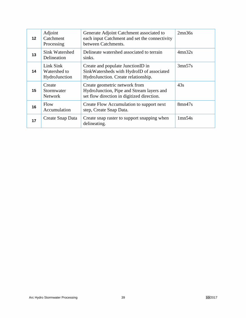
Arc Hydro Stormwater Processing 39 10/2017
12
Adjoint
Catchment
Processing
Generate Adjoint Catchment associated to
each input Catchment and set the connectivity
between Catchments.
2mn36s
13 Sink Watershed
Delineation
Delineate watershed associated to terrain
sinks.
4mn32s
14
Link Sink
Watershed to
HydroJunction
Create and populate JunctionID in
SinkWatersheds with HydroID of associated
HydroJunction. Create relationship.
3mn57s
15
Create
Stormwater
Network
Create geometric network from
HydroJunction, Pipe and Stream layers and
set flow direction in digitized direction.
43s
16 Flow
Accumulation
Create Flow Accumulation to support next
step, Create Snap Data.
8mn47s
17 Create Snap Data Create snap raster to support snapping when
delineating.
1mn54s
Arc Hydro Stormwater Processing 40 10/2017
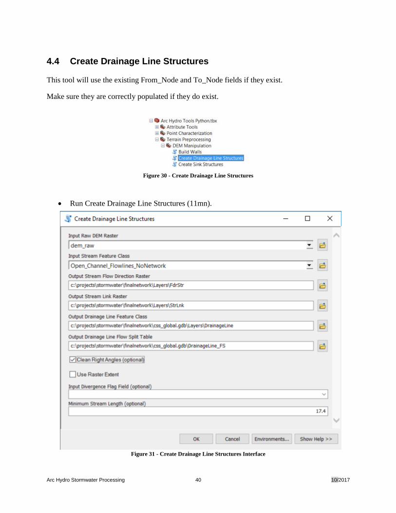
4.4 Create Drainage Line Structures
This tool will use the existing From_Node and To_Node fields if they exist.
Make sure they are correctly populated if they do exist.
Figure 30 - Create Drainage Line Structures
• Run Create Drainage Line Structures (11mn).
Figure 31 - Create Drainage Line Structures Interface
Arc Hydro Stormwater Processing 41 10/2017
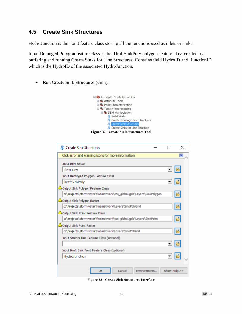
4.5 Create Sink Structures
HydroJunction is the point feature class storing all the junctions used as inlets or sinks.
Input Deranged Polygon feature class is the DraftSinkPoly polygon feature class created by
buffering and running Create Sinks for Line Structures. Contains field HydroID and JunctionID
which is the HydroID of the associated HydroJunction.
• Run Create Sink Structures (6mn).
Figure 32 - Create Sink Structures Tool
Figure 33 - Create Sink Structures Interface

Arc Hydro Stormwater Processing 42 10/2017
After running the tool, review the data and make sure that there are no sink point features located
on top of stream grid cells. You can use the ExtractMultiValuesToPoints tool to identify those
locations. If any points are located on streams, edit the input Stream layer so that the stream grid
moves to a neighboring cell and rerun the previous step, Create Drainage Line Structures.
Arc Hydro Stormwater Processing 43 10/2017
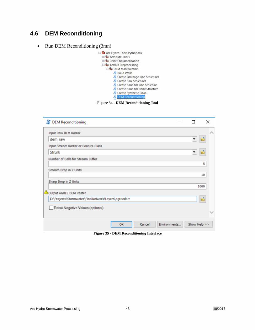
4.6 DEM Reconditioning
• Run DEM Reconditioning (3mn).
Figure 34 - DEM Reconditioning Tool
Figure 35 - DEM Reconditioning Interface
Arc Hydro Stormwater Processing 44 10/2017
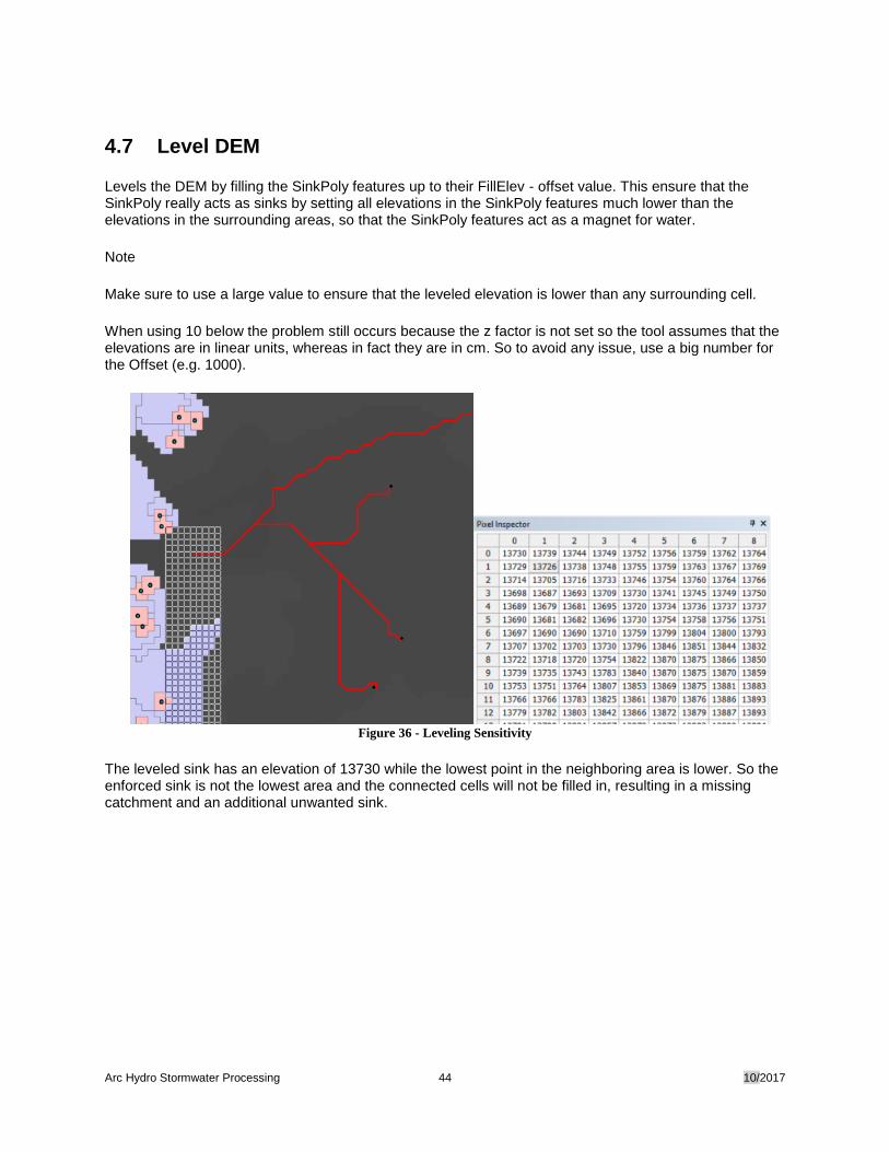
4.7 Level DEM
Levels the DEM by filling the SinkPoly features up to their FillElev - offset value. This ensure that the SinkPoly really acts as sinks by setting all elevations in the SinkPoly features much lower than the elevations in the surrounding areas, so that the SinkPoly features act as a magnet for water.
Note
Make sure to use a large value to ensure that the leveled elevation is lower than any surrounding cell.
When using 10 below the problem still occurs because the z factor is not set so the tool assumes that the elevations are in linear units, whereas in fact they are in cm. So to avoid any issue, use a big number for the Offset (e.g. 1000).
Figure 36 - Leveling Sensitivity
The leveled sink has an elevation of 13730 while the lowest point in the neighboring area is lower. So the enforced sink is not the lowest area and the connected cells will not be filled in, resulting in a missing catchment and an additional unwanted sink.
Arc Hydro Stormwater Processing 45 10/2017
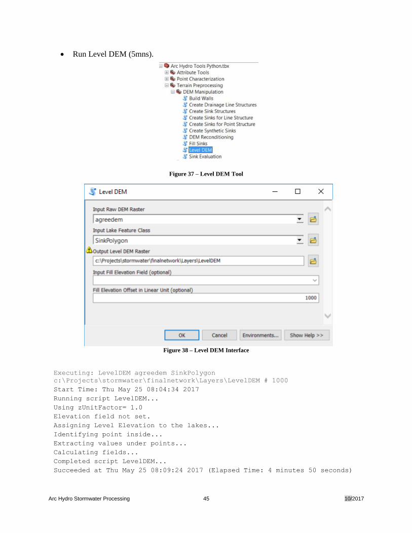
• Run Level DEM (5mns).
Figure 37 – Level DEM Tool
Figure 38 – Level DEM Interface
Executing: LevelDEM agreedem SinkPolygon
c:\Projects\stormwater\finalnetwork\Layers\LevelDEM # 1000
Start Time: Thu May 25 08:04:34 2017
Running script LevelDEM...
Using zUnitFactor= 1.0
Elevation field not set.
Assigning Level Elevation to the lakes...
Identifying point inside...
Extracting values under points...
Calculating fields...
Completed script LevelDEM...
Succeeded at Thu May 25 08:09:24 2017 (Elapsed Time: 4 minutes 50 seconds)
Arc Hydro Stormwater Processing 46 10/2017
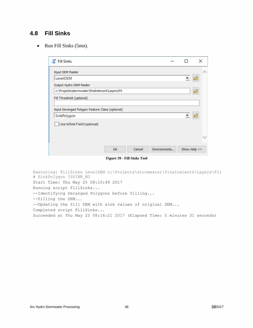
4.8 Fill Sinks
• Run Fill Sinks (5mn).
Figure 39 - Fill Sinks Tool
Executing: FillSinks LevelDEM c:\Projects\stormwater\finalnetwork\Layers\Fil
# SinkPolygon ISSINK_NO
Start Time: Thu May 25 08:10:49 2017
Running script FillSinks...
--Identifying Deranged Polygons before filling...
--Filling the DEM...
--Updating the fill DEM with sink values of original DEM...
Completed script FillSinks...
Succeeded at Thu May 25 08:16:21 2017 (Elapsed Time: 5 minutes 31 seconds)
Arc Hydro Stormwater Processing 47 10/2017
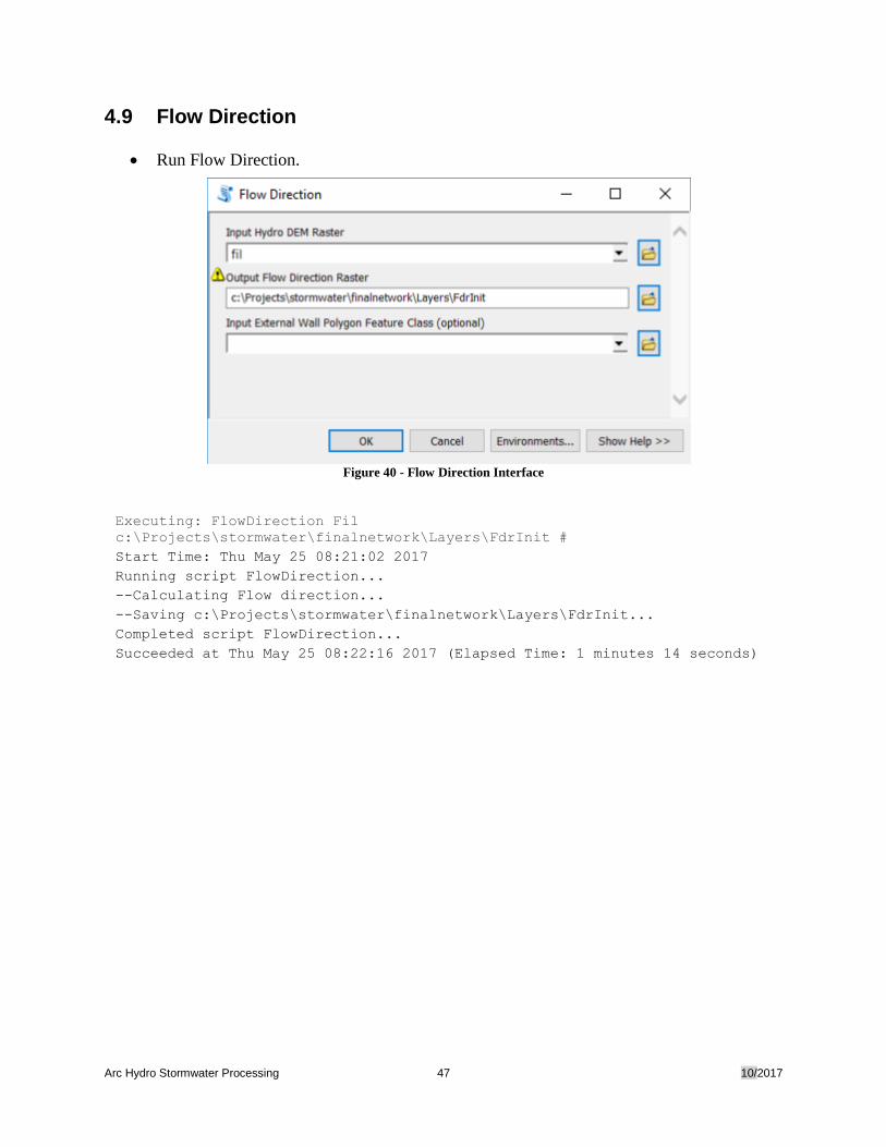
4.9 Flow Direction
• Run Flow Direction.
Figure 40 - Flow Direction Interface
Executing: FlowDirection Fil
c:\Projects\stormwater\finalnetwork\Layers\FdrInit #
Start Time: Thu May 25 08:21:02 2017
Running script FlowDirection...
--Calculating Flow direction...
--Saving c:\Projects\stormwater\finalnetwork\Layers\FdrInit...
Completed script FlowDirection...
Succeeded at Thu May 25 08:22:16 2017 (Elapsed Time: 1 minutes 14 seconds)
Arc Hydro Stormwater Processing 48 10/2017
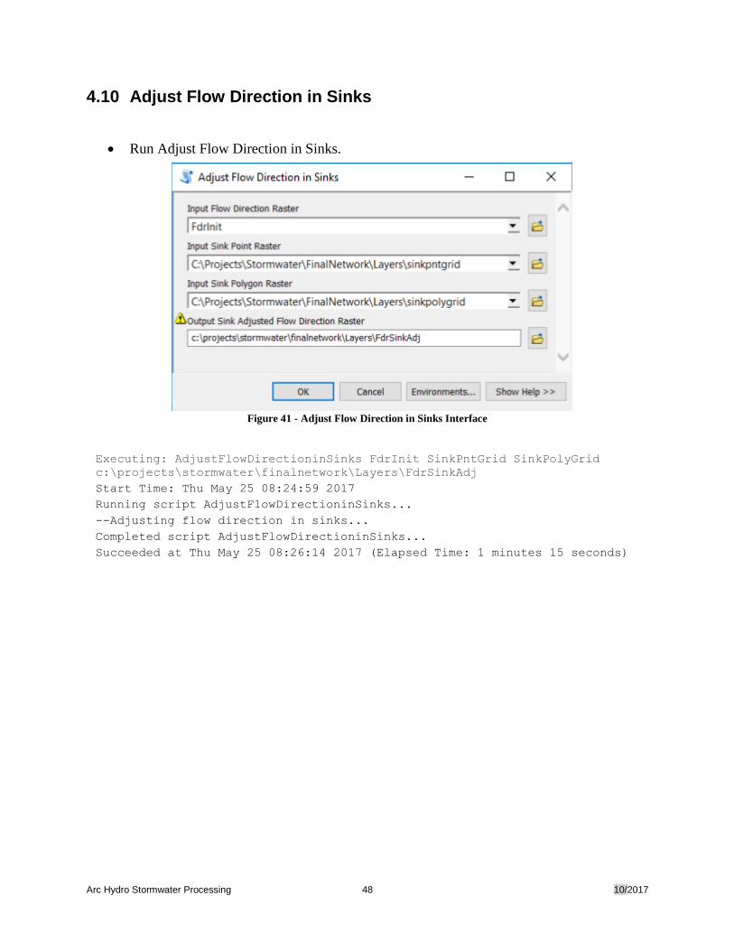
4.10 Adjust Flow Direction in Sinks
• Run Adjust Flow Direction in Sinks.
Figure 41 - Adjust Flow Direction in Sinks Interface
Executing: AdjustFlowDirectioninSinks FdrInit SinkPntGrid SinkPolyGrid
c:\projects\stormwater\finalnetwork\Layers\FdrSinkAdj
Start Time: Thu May 25 08:24:59 2017
Running script AdjustFlowDirectioninSinks...
--Adjusting flow direction in sinks...
Completed script AdjustFlowDirectioninSinks...
Succeeded at Thu May 25 08:26:14 2017 (Elapsed Time: 1 minutes 15 seconds)
Arc Hydro Stormwater Processing 49 10/2017
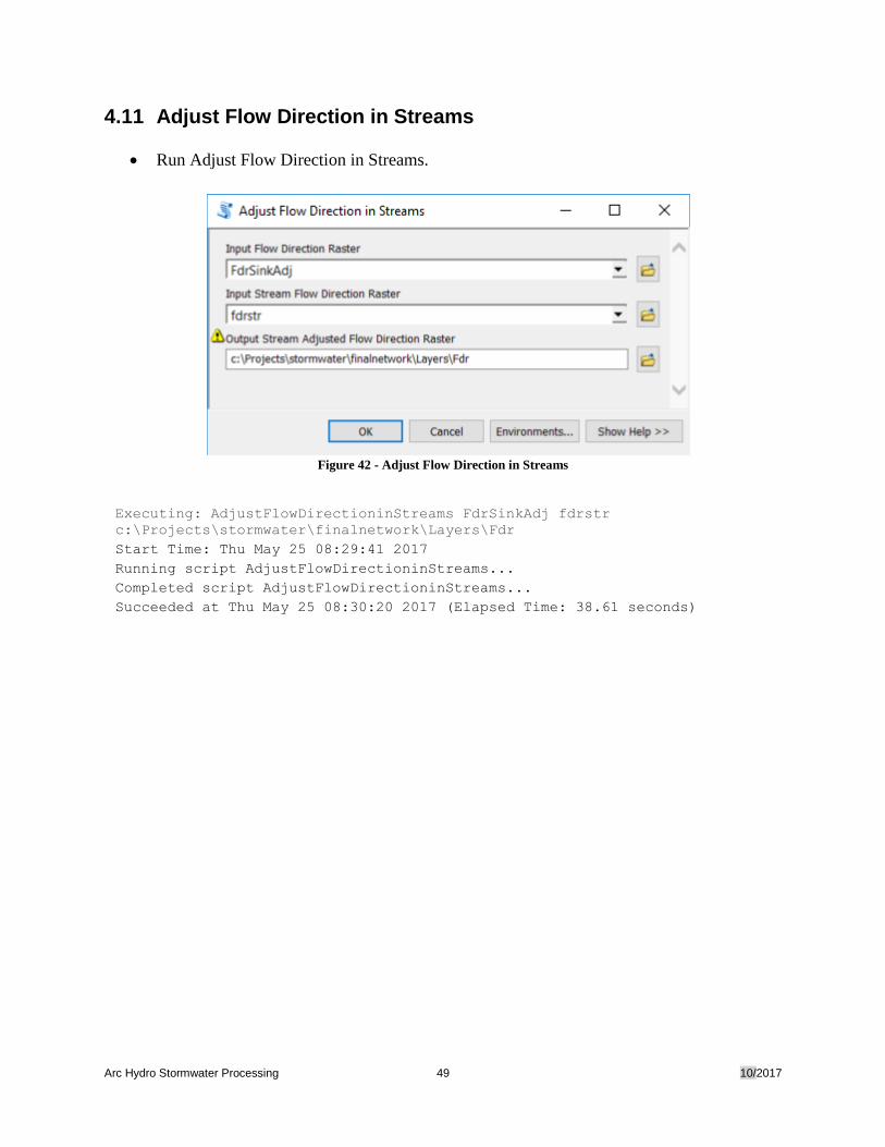
4.11 Adjust Flow Direction in Streams
• Run Adjust Flow Direction in Streams.
Figure 42 - Adjust Flow Direction in Streams
Executing: AdjustFlowDirectioninStreams FdrSinkAdj fdrstr
c:\Projects\stormwater\finalnetwork\Layers\Fdr
Start Time: Thu May 25 08:29:41 2017
Running script AdjustFlowDirectioninStreams...
Completed script AdjustFlowDirectioninStreams...
Succeeded at Thu May 25 08:30:20 2017 (Elapsed Time: 38.61 seconds)
Arc Hydro Stormwater Processing 50 10/2017
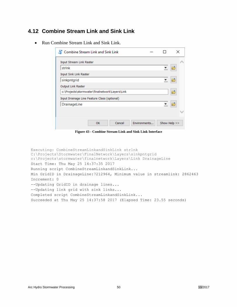
4.12 Combine Stream Link and Sink Link
• Run Combine Stream Link and Sink Link.
Figure 43 - Combine Stream Link and Sink Link Interface
Executing: CombineStreamLinkandSinkLink strlnk
C:\Projects\Stormwater\FinalNetwork\Layers\sinkpntgrid
c:\Projects\stormwater\finalnetwork\Layers\Link DrainageLine
Start Time: Thu May 25 14:37:35 2017
Running script CombineStreamLinkandSinkLink...
Min GridID in DrainageLine:7212964, Minimum value in streamlink: 2862463
Increment: 0
--Updating GridID in drainage lines...
--Updating link grid with sink links...
Completed script CombineStreamLinkandSinkLink...
Succeeded at Thu May 25 14:37:58 2017 (Elapsed Time: 23.55 seconds)
Arc Hydro Stormwater Processing 51 10/2017
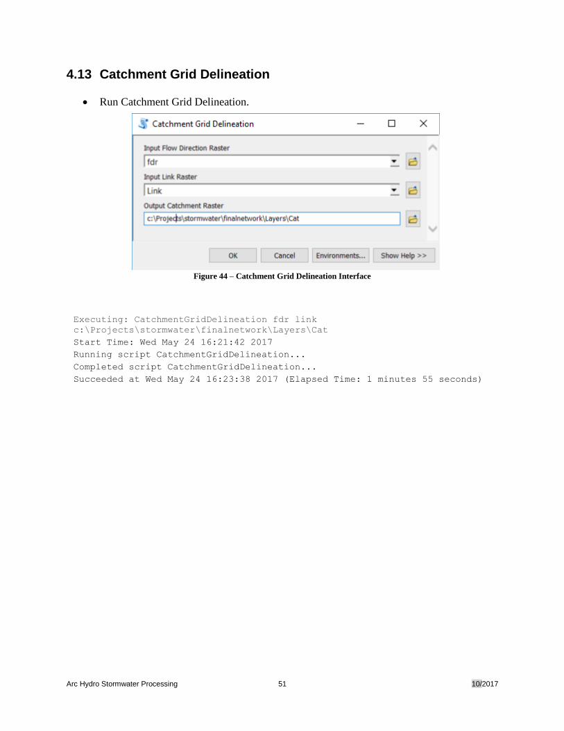
4.13 Catchment Grid Delineation
• Run Catchment Grid Delineation.
Figure 44 – Catchment Grid Delineation Interface
Executing: CatchmentGridDelineation fdr link
c:\Projects\stormwater\finalnetwork\Layers\Cat
Start Time: Wed May 24 16:21:42 2017
Running script CatchmentGridDelineation...
Completed script CatchmentGridDelineation...
Succeeded at Wed May 24 16:23:38 2017 (Elapsed Time: 1 minutes 55 seconds)
Arc Hydro Stormwater Processing 52 10/2017
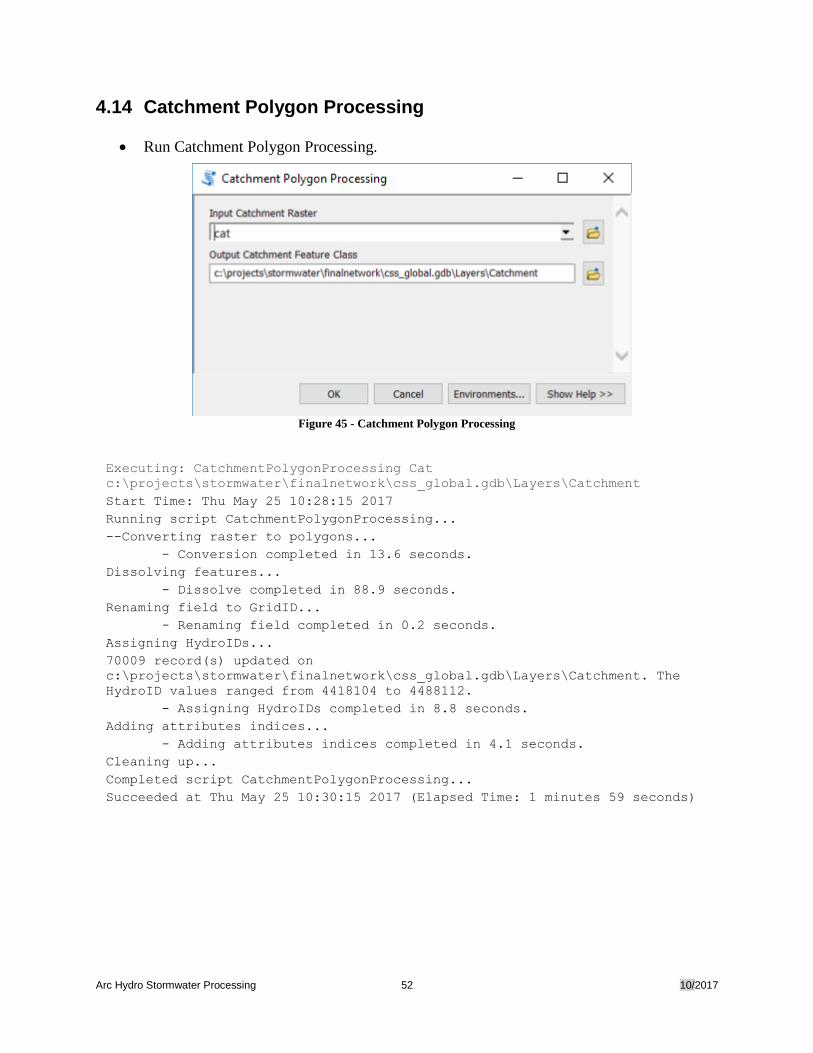
4.14 Catchment Polygon Processing
• Run Catchment Polygon Processing.
Figure 45 - Catchment Polygon Processing
Executing: CatchmentPolygonProcessing Cat
c:\projects\stormwater\finalnetwork\css_global.gdb\Layers\Catchment
Start Time: Thu May 25 10:28:15 2017
Running script CatchmentPolygonProcessing...
--Converting raster to polygons...
- Conversion completed in 13.6 seconds.
Dissolving features...
- Dissolve completed in 88.9 seconds.
Renaming field to GridID...
- Renaming field completed in 0.2 seconds.
Assigning HydroIDs...
70009 record(s) updated on
c:\projects\stormwater\finalnetwork\css_global.gdb\Layers\Catchment. The
HydroID values ranged from 4418104 to 4488112.
- Assigning HydroIDs completed in 8.8 seconds.
Adding attributes indices...
- Adding attributes indices completed in 4.1 seconds.
Cleaning up...
Completed script CatchmentPolygonProcessing...
Succeeded at Thu May 25 10:30:15 2017 (Elapsed Time: 1 minutes 59 seconds)
Arc Hydro Stormwater Processing 53 10/2017
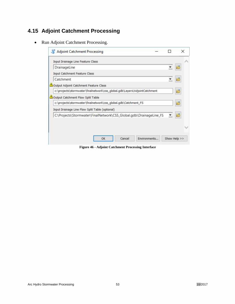
4.15 Adjoint Catchment Processing
• Run Adjoint Catchment Processing.
Figure 46 - Adjoint Catchment Processing Interface
Arc Hydro Stormwater Processing 54 10/2017
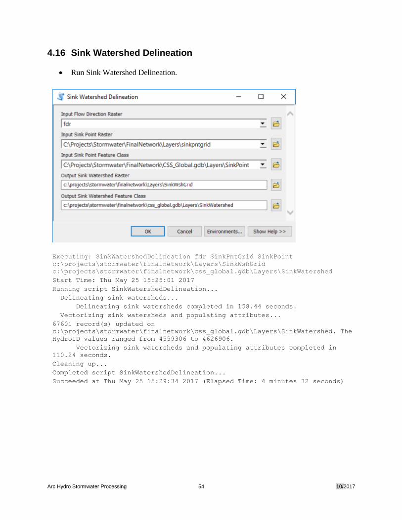
4.16 Sink Watershed Delineation
• Run Sink Watershed Delineation.
Executing: SinkWatershedDelineation fdr SinkPntGrid SinkPoint
c:\projects\stormwater\finalnetwork\Layers\SinkWshGrid
c:\projects\stormwater\finalnetwork\css_global.gdb\Layers\SinkWatershed
Start Time: Thu May 25 15:25:01 2017
Running script SinkWatershedDelineation...
Delineating sink watersheds...
Delineating sink watersheds completed in 158.44 seconds.
Vectorizing sink watersheds and populating attributes...
67601 record(s) updated on
c:\projects\stormwater\finalnetwork\css_global.gdb\Layers\SinkWatershed. The
HydroID values ranged from 4559306 to 4626906.
Vectorizing sink watersheds and populating attributes completed in
110.24 seconds.
Cleaning up...
Completed script SinkWatershedDelineation...
Succeeded at Thu May 25 15:29:34 2017 (Elapsed Time: 4 minutes 32 seconds)
Arc Hydro Stormwater Processing 55 10/2017
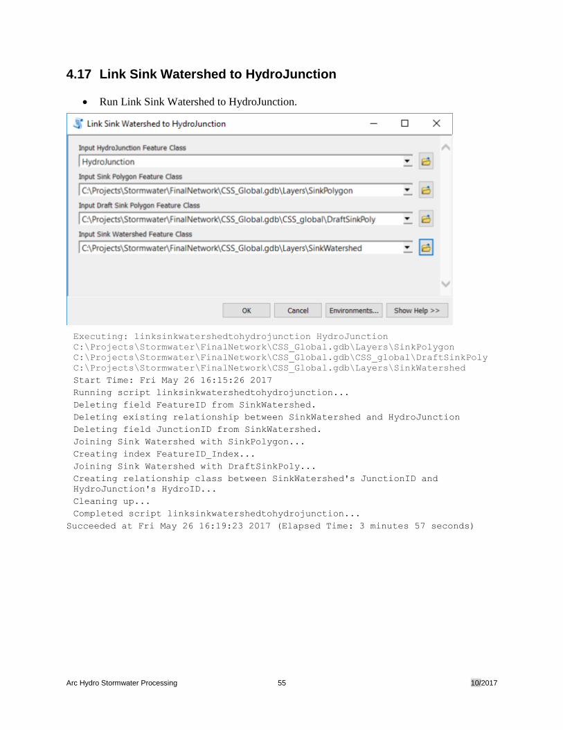
4.17 Link Sink Watershed to HydroJunction
• Run Link Sink Watershed to HydroJunction.
Executing: linksinkwatershedtohydrojunction HydroJunction
C:\Projects\Stormwater\FinalNetwork\CSS_Global.gdb\Layers\SinkPolygon
C:\Projects\Stormwater\FinalNetwork\CSS_Global.gdb\CSS_global\DraftSinkPoly
C:\Projects\Stormwater\FinalNetwork\CSS_Global.gdb\Layers\SinkWatershed
Start Time: Fri May 26 16:15:26 2017
Running script linksinkwatershedtohydrojunction...
Deleting field FeatureID from SinkWatershed.
Deleting existing relationship between SinkWatershed and HydroJunction
Deleting field JunctionID from SinkWatershed.
Joining Sink Watershed with SinkPolygon...
Creating index FeatureID_Index...
Joining Sink Watershed with DraftSinkPoly...
Creating relationship class between SinkWatershed's JunctionID and
HydroJunction's HydroID...
Cleaning up...
Completed script linksinkwatershedtohydrojunction...
Succeeded at Fri May 26 16:19:23 2017 (Elapsed Time: 3 minutes 57 seconds)

Arc Hydro Stormwater Processing 56 10/2017
4.18 Create Stormwater Network
• Run Create Stormwater Network.
The tool creates a geometric network from Pipe, Stream and HydroJunction and set the flow
direction in the lines to the digitized direction.
Arc Hydro Stormwater Processing 57 10/2017
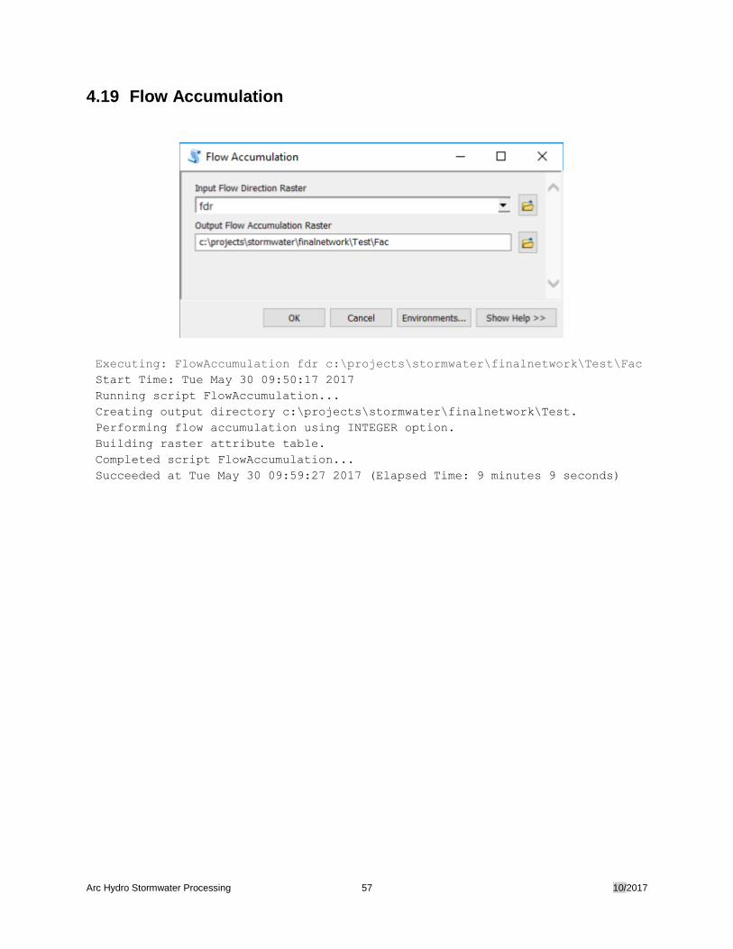
4.19 Flow Accumulation
Executing: FlowAccumulation fdr c:\projects\stormwater\finalnetwork\Test\Fac
Start Time: Tue May 30 09:50:17 2017
Running script FlowAccumulation...
Creating output directory c:\projects\stormwater\finalnetwork\Test.
Performing flow accumulation using INTEGER option.
Building raster attribute table.
Completed script FlowAccumulation...
Succeeded at Tue May 30 09:59:27 2017 (Elapsed Time: 9 minutes 9 seconds)
Arc Hydro Stormwater Processing 58 10/2017
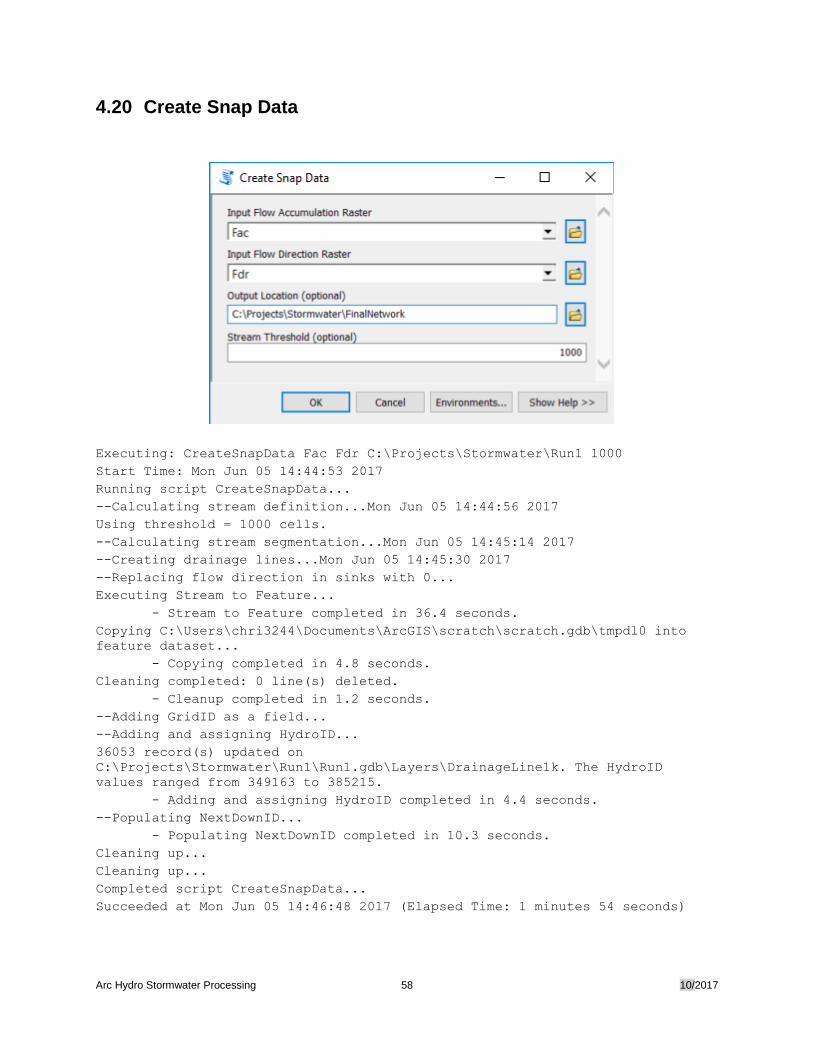
4.20 Create Snap Data
Executing: CreateSnapData Fac Fdr C:\Projects\Stormwater\Run1 1000
Start Time: Mon Jun 05 14:44:53 2017
Running script CreateSnapData...
--Calculating stream definition...Mon Jun 05 14:44:56 2017
Using threshold = 1000 cells.
--Calculating stream segmentation...Mon Jun 05 14:45:14 2017
--Creating drainage lines...Mon Jun 05 14:45:30 2017
--Replacing flow direction in sinks with 0...
Executing Stream to Feature...
- Stream to Feature completed in 36.4 seconds.
Copying C:\Users\chri3244\Documents\ArcGIS\scratch\scratch.gdb\tmpdl0 into
feature dataset...
- Copying completed in 4.8 seconds.
Cleaning completed: 0 line(s) deleted.
- Cleanup completed in 1.2 seconds.
--Adding GridID as a field...
--Adding and assigning HydroID...
36053 record(s) updated on
C:\Projects\Stormwater\Run1\Run1.gdb\Layers\DrainageLine1k. The HydroID
values ranged from 349163 to 385215.
- Adding and assigning HydroID completed in 4.4 seconds.
--Populating NextDownID...
- Populating NextDownID completed in 10.3 seconds.
Cleaning up...
Cleaning up...
Completed script CreateSnapData...
Succeeded at Mon Jun 05 14:46:48 2017 (Elapsed Time: 1 minutes 54 seconds)
Arc Hydro Stormwater Processing 59 10/2017
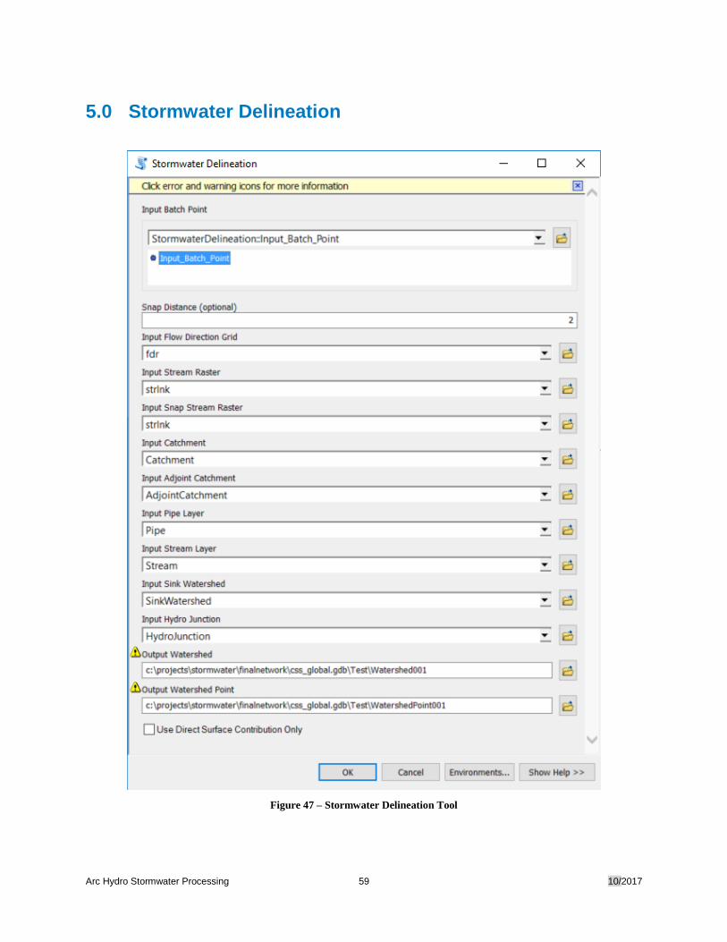
5.0 Stormwater Delineation
Figure 47 – Stormwater Delineation Tool
Arc Hydro Stormwater Processing 60 10/2017
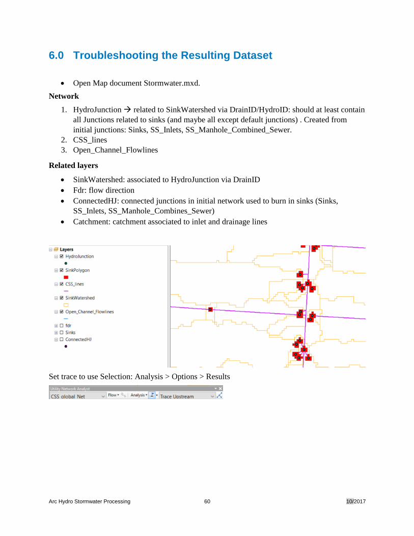
6.0 Troubleshooting the Resulting Dataset
• Open Map document Stormwater.mxd.
Network
1. HydroJunction related to SinkWatershed via DrainID/HydroID: should at least contain
all Junctions related to sinks (and maybe all except default junctions) . Created from
initial junctions: Sinks, SS_Inlets, SS_Manhole_Combined_Sewer.
2. CSS_lines
3. Open_Channel_Flowlines
Related layers
• SinkWatershed: associated to HydroJunction via DrainID
• Fdr: flow direction
• ConnectedHJ: connected junctions in initial network used to burn in sinks (Sinks,
SS_Inlets, SS_Manhole_Combines_Sewer)
• Catchment: catchment associated to inlet and drainage lines
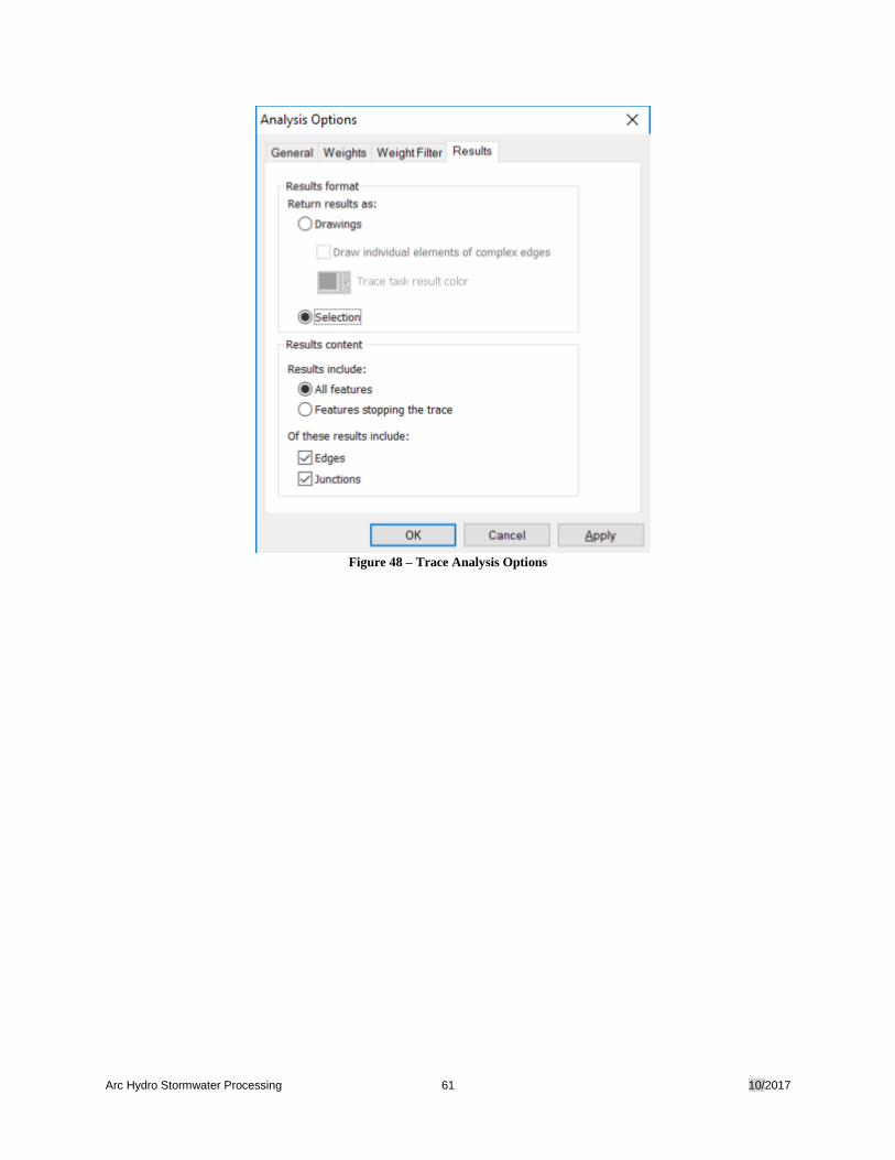
Set trace to use Selection: Analysis > Options > Results
Arc Hydro Stormwater Processing 61 10/2017
Figure 48 – Trace Analysis Options
Arc Hydro Stormwater Processing 62 10/2017
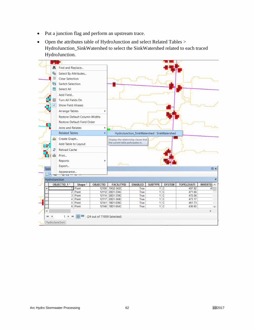
• Put a junction flag and perform an upstream trace.
• Open the attributes table of HydroJunction and select Related Tables >
HydroJunction_SinkWatershed to select the SinkWatershed related to each traced
HydroJunction.
Arc Hydro Stormwater Processing 63 10/2017
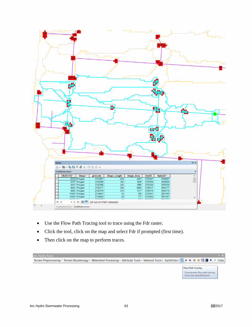
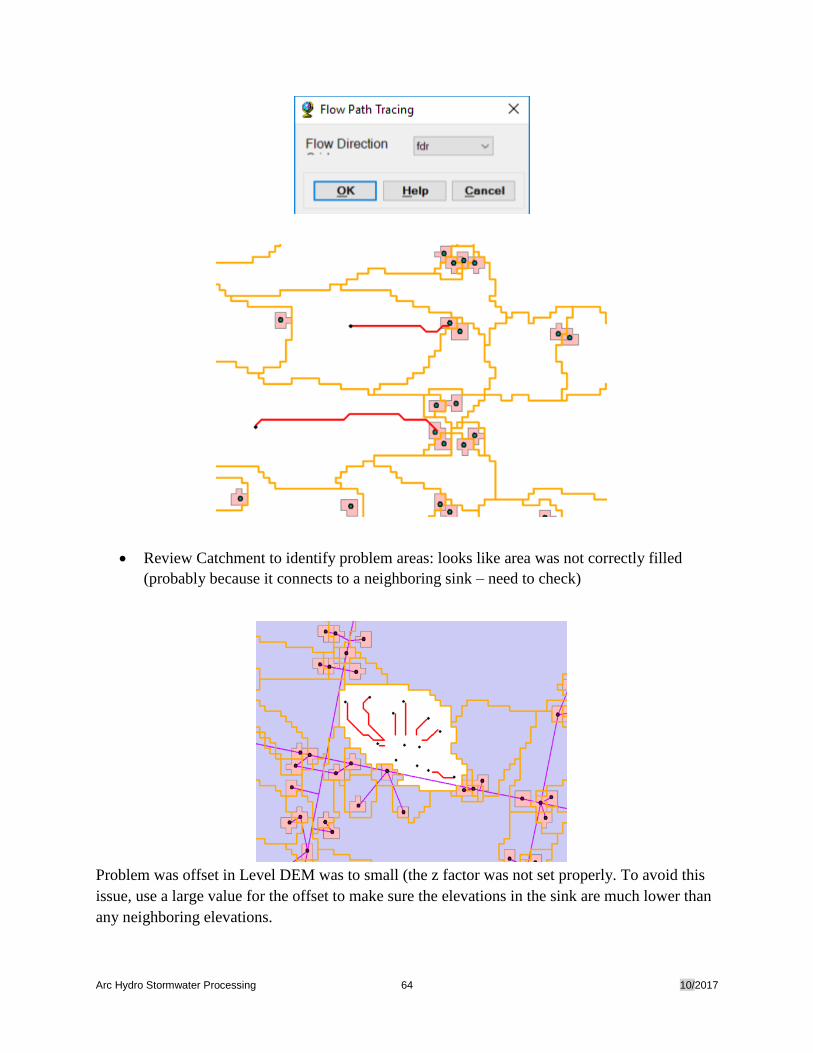
• Use the Flow Path Tracing tool to trace using the Fdr raster.
• Click the tool, click on the map and select Fdr if prompted (first time).
• Then click on the map to perform traces.
Arc Hydro Stormwater Processing 64 10/2017
• Review Catchment to identify problem areas: looks like area was not correctly filled
(probably because it connects to a neighboring sink – need to check)
Problem was offset in Level DEM was to small (the z factor was not set properly. To avoid this
issue, use a large value for the offset to make sure the elevations in the sink are much lower than
any neighboring elevations.
Arc Hydro Stormwater Processing 65 10/2017
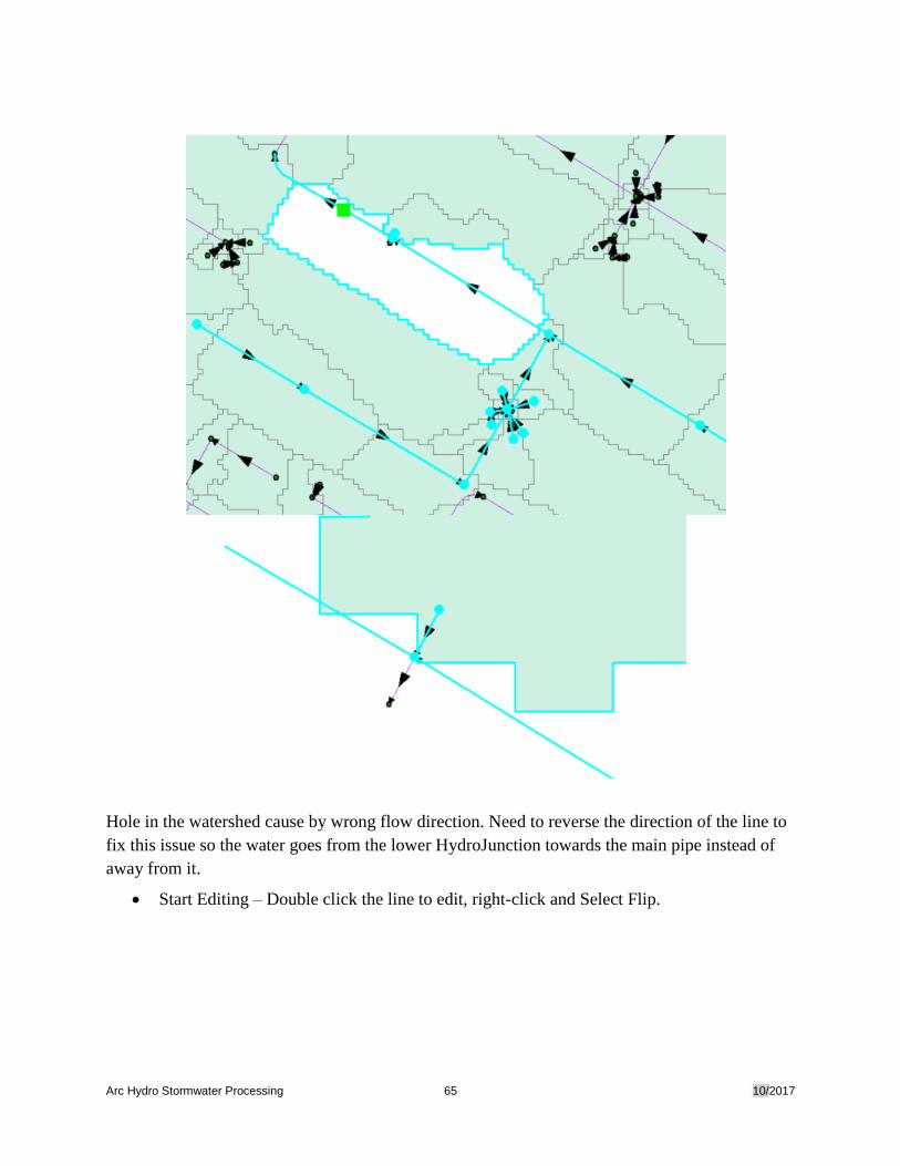
Hole in the watershed cause by wrong flow direction. Need to reverse the direction of the line to
fix this issue so the water goes from the lower HydroJunction towards the main pipe instead of
away from it.
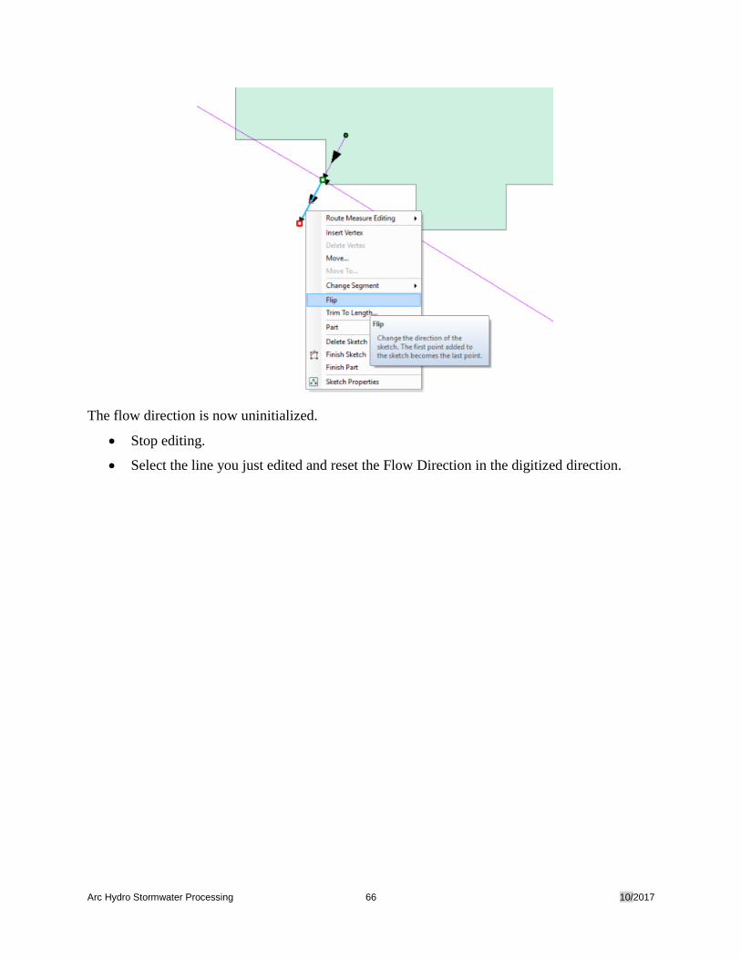
• Start Editing – Double click the line to edit, right-click and Select Flip.
Arc Hydro Stormwater Processing 66 10/2017
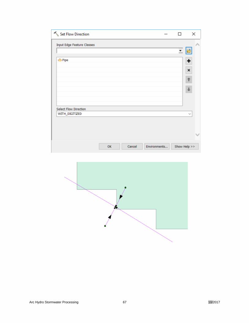
The flow direction is now uninitialized.
• Stop editing.
• Select the line you just edited and reset the Flow Direction in the digitized direction.
Arc Hydro Stormwater Processing 67 10/2017
Arc Hydro Stormwater Processing 68 10/2017
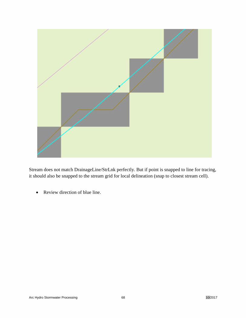
Stream does not match DrainageLine/StrLnk perfectly. But if point is snapped to line for tracing,
it should also be snapped to the stream grid for local delineation (snap to closest stream cell).
• Review direction of blue line.
Arc Hydro Stormwater Processing 69 10/2017
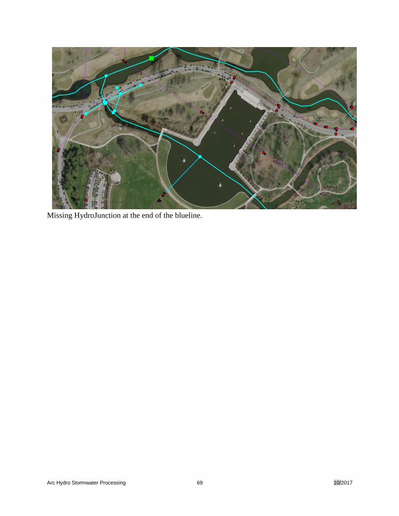
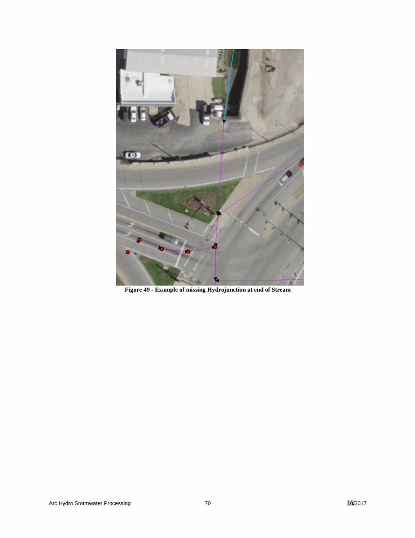
Missing HydroJunction at the end of the blueline.
Arc Hydro Stormwater Processing 70 10/2017
Figure 49 - Example of missing Hydrojunction at end of Stream

Arc Hydro Stormwater Processing 71 10/2017
Copyright © 2017 Esri
All rights reserved.
Printed in the United States of America. Notice of Proprietary Information:
The information in the attached document is proprietary to Esri and contains commercial or financial information or trade secrets
that are confidential and exempt from disclosure to the public under the Freedom of Information Act. This information shall not
be disclosed outside of Customer’s organization (except for consultants under a confidentiality obligation who are involved in the
proposal evaluation process) without Esri’s prior permission, and shall not be duplicated, used, or disclosed in whole or in part
for any purpose other than to evaluate this proposal. If, however, a contract is awarded to Esri as a result of this information, the
Customer shall have the right to duplicate, use, or disclose the data to the extent provided in the contract. This restriction does not
limit the Customer’s right to use information contained in this data if it is obtained from another source without restriction.
Esri, the Esri globe logo, CLIENT GIS, esri.com, and other Esri marks used in this document are trademarks, service marks, or
registered marks of Esri in the United States, the European Community, or certain other jurisdictions. Other companies and
products or services mentioned herein may be trademarks, service marks, or registered marks of their respective mark owners.