Embed Size (px)
Citation preview
Technical Data TD008014EN Effective July 2020
ContentsDescription Page
Product description . . . . . . . . . . . . . . . . . . . . . . 2Product assembly platforms . . . . . . . . . . . . . . . . 2Certifications . . . . . . . . . . . . . . . . . . . . . . . . . . . 2Relay features . . . . . . . . . . . . . . . . . . . . . . . . . . . 3System diagram . . . . . . . . . . . . . . . . . . . . . . . . . 5Incident energy calculation description . . . . . . . 6Incident energy reduction curves . . . . . . . . . . . . 6Wiring diagram . . . . . . . . . . . . . . . . . . . . . . . . . 14Ground fault response curve . . . . . . . . . . . . . . 14Zone interlock . . . . . . . . . . . . . . . . . . . . . . . . . . 15Trip curves . . . . . . . . . . . . . . . . . . . . . . . . . . . . . 16 Catalog number structures . . . . . . . . . . . . . . . . 22Relay test instruction . . . . . . . . . . . . . . . . . . . . 24
Arc energy reduction relayswitching devices product platforms
2
Technical Data TD008014ENEffective July 2020
Arc energy reduction relay switching devices product platforms
EATON www.eaton.com
WARNING(1) ONLY QUALIFIED ELECTRICAL PERSONNEL SHOULD BE PERMITTED TO WORK ON THE EQUIPMENT. (2) DO NOT ATTEMPT TO INSTALL OR PERFORM MAINTENANCE ON THE EQUIPMENT WHILE ENERGIZED. ALWAYS VERIFY THAT NO VOLTAGE IS PRESENT BEFORE PROCEEDING. (3) ALWAYS DE-ENERGIZE PRIMARY AND SECONDARY CIRCUITS BEFORE REMOVING CIRCUIT BREAKER. FAILURE TO FOLLOW THESE STEPS FOR ALL PROCEDURES DESCRIBED IN THIS INSTRUCTION LEAFLET COULD RESULT IN DEATH, BODILY INJURY, OR PROPERTY DAMAGE.
CAUTIONSPECIFIC OPERATING PROCEDURES MUST BE DEVELOPED BY THE RESPONSIBLE PARTY, BECAUSE OF THE UNIQUE APPLICATION AND VAST VARIETY OF SYSTEM AND USER REQUIREMENTS. FAILURE TO DEVELOP SPECIFIC PROCEDURES COULD LEAD TO IMPROPER USE OR OTHER MORE SERIOUS CONSEQUENCES.
DANGERHAZARDOUS VOLTAGE. WILL CAUSE SEVERE INJURY OR DEATH. DO NOT OPEN SHUTTER IF THE EQUIPMENT IS ENERGIZED.
Product descriptionArc energy reduction relay switching devices
Arc fault/overcurrent/ground fault relay
• Provides arc energy reduction per NEC® 240 .67 • Provides class 1 ground fault protection• Provides overcurrent protection
Ratings
• Input power options: 120 Vac• Frequency: 50/60 Hz• Ground fault: Trip currents settings 100–1200 A (adjustable)• Input withstand: 200,000 amperes rms for 3 cycles, 50/60 Hz• Ambient temperature range: –30 to +60 °C
Contact ratings
Ground fault• 1NO, dry-type, 120 Vac, 5 A continuous
Overload/arc reduction• 1NO, dry-type, 120 Vac, 5 A continuous
ote: N Additional contacts available based on application and final product assembly .
Product assembly platformsProduct platforms integrating the arc energy reduction relay
• Heavy-duty shunt trip safety switches• Pringle™ bolted pressure contact switches• Fusible panelboard switches
Relay capabilities a
• Arc energy reduction• Overcurrent protection• Class 1 ground fault protection• Ground fault relay zone interlock option
Ratings
• 400 A, 600 A, 800 A, 1200 A, 1600 A, 2000 A, 2500 A, 3000 A, 4000 A, 5000 A, 6000 A
CertificationsRelay standards and certifications
• UL®
aRelays must be used with the correct tested and listed sensors.

3
Technical Data TD008014ENEffective July 2020
Arc energy reduction relay switching devices product platforms
EATON www.eaton.com
Relay features
11
10
9
8 74
6
5
3
21
Figure 1. Relay feature detail
Legend
Item number Description
1 Ground fault current level indicating bar Indicates level of ground fault.
2 Current injection test button(s) Provide primary current injection to current transformers to comply
with 230.95(C). Current injection will trip relay for each phase or neutral CT. Trip bypass button may be depressed simultaneously to avoid tripping the switch during the test. Power to relay is required.
3 Positive visual trip indicator Physical indicator and reset for overcurrent condition
4 Overcurrent trip test Overcurrent trip test select to comply with NEC 240.67(C)
5 Indicator for overcurrent condition Blinking LED during Time Delay and Solid Red LED after Trip, if
power is still available6 Overcurrent time delay dial
Sets the overcurrent response curve to allow coordination with the fuse time/current curve (see examples on page 6)
Item number Description
7 Maintenance Mode selector switch and indicating light Maintenance switch provides physical means to activate energy
reducing maintenance mode. • Both the Mode switch on the panel and the remote switch
(if used) must be in the OFF (closed) position for the unit to be in “Normal Mode”
• If the remote switch is not used, a jumper must be placed across the terminals
• If the AFGF detects a ground fault while in the Maintenance Mode, the relay will trip instantaneously when the Pick Up Amps setting is reached, regardless of the time delay setting
• While in Maintenance Mode, the Overcurrent trip setting is reduced to instantaneous trip at 250% switch rating
• Indications: LED (Red) = Unit in Maintenance Mode; LED (Green) = Unit in Normal Mode
8 Ground fault time delay setting If the ground fault level exceeds the setpoint for the duration of the
time delay, the ground fault contacts will change state. If power is still available, the AFGF will continue to indicate the level the ground fault current was at the time of the trip. The ground fault must be present for the full length of the time delay.
9 Ground fault Pick Up Amps setting If the ground fault exceeds the set level, “Pick Up Amps”, the GF time
delay will begin. The ground fault amperage level does not affect the time delay
10 Ground fault shunt trip bypass See page 24 for relay test instructions
11 Ground fault trip indicator Physical indicator and reset for ground fault condition

4
Technical Data TD008014ENEffective July 2020
Arc energy reduction relay switching devices product platforms
EATON www.eaton.com
Overcurrent trip settings
Example 1
Table 1. Nameplate = 1200 A / delay setting = 200 secondsOvercurrent Trip time
2400 A 200 seconds3600 A 60 seconds4800 A 12 seconds6000 A 6 seconds7200 A Instantaneous
Example 2
Table 2. Nameplate = 800 A / delay setting = 100 secondsOvercurrent Trip time
1600 A 100 seconds2400 A 30 seconds3200 A 6 seconds4000 A 3 seconds4800 A Instantaneous
Arc energy reduction
NEC requirement
NFPA 70, NEC, article 240 .67 focuses on fusible devices rated 1200 A and higher . Below is the specific article verbiage:
240.67 Arc Energy Reduction . Where fuses rated 1200 A or higher are installed, 240 .67(A) and 240 .67(B) shall apply . This requirement shall become effective January 1, 2020 .
240.67(A) Documentation . Documentation shall be available to those authorized to design, install, operate, or inspect the instal-lation as to the location of the fuses .
Documentation shall also be provided to demonstrate that the method chosen to reduce the clearing time is set to operate at a value below the available arcing current .
240.67(B) Method to Reduce Clearing Time . A fuse shall have a clearing time of 0 .07 seconds or less at the available arcing current, or one of the following shall be provided and shall be set to operate at less than the available arcing current:
(1) Differential relaying
(2) Energy-reducing maintenance switching with local status indicator
(3) Energy-reducing active arc flash mitigation system
(4) Current limiting electrically actuated fuses
(5) An approved equivalent means .
Informational note 1: An energy-reducing maintenance switch allows a worker to set a disconnect switch to reduce the clearing time while the worker is working within an arc-flash boundary as defined in NFPA 70E-2018, Standard for Electrical Safety in the Workplace, and then to set the disconnect switch back to a normal setting after the potentially hazardous work is complete .
Informational note 2: An energy-reducing active arc-flash mitigation system helps in reducing arcing duration in the electrical distribution system . No change in the disconnect switch or the settings of other devices is required during maintenance when a worker is working within an arc-flash boundary as defined in NFPA 70E-2018, Standard for Electrical Safety in the Workplace .
Informational note 3: IEEET 1584-2002 . IEEE Guide for Performing Arc Flash Hazard Calculations, is one of the available methods that provides guidance in determining arcing current .
240.67(C) Performance Testing . The energy reduction protec-tion system shall be performance tested by primary current injection testing or another approved method when first installed on-site . This testing shall be performed by a qualified person(s) in accordance with the manufacturer’s instructions .
A written record of this testing shall be made and shall be available to the authority having jurisdiction .
Informational note: Some energy reduction protection systems cannot be tested using a test process of primary current injection due to either the protection method being damaged such as with the use of fuse technology or because current is not the primary method of arc detection .
NEC 240.67 Compliance
The arc fault ground fault (AFGF) relay complies with NEC 240 .67 by:
240.67(A). The AFGF relay maintenance mode is designed to always operate at 250% of the switch rating .
240.67(B). The AFGF relay incorporates energy-reducing maintenance switch with local status indication . The relay senses current above 250% and sends a trip signal to the switch . See page 3, item number 6 .
240.67(C). Current injection testing functionality is built into the relay and current transformer combination with a push to test feature .
Relay operation in maintenance mode
The AFGF relay measures the current in the system and determines in milliseconds if a fault is occurring and changes the state of the relay output . State changes without delay above 250% of the switch rating in maintenance mode . The relay may open the switch to clear the fault before the fuse has time to clear (depending on the fault level and the fuse chosen) . The fuse will clear high-level arcing faults for which they are designed . For faults that are between high-level and low-level arcing faults, both the fuse will clear and the relay will open the switch .
Relay operation in normal mode
State changes without delay above 600% of the switch rating in normal mode .
5
Technical Data TD008014ENEffective July 2020
Arc energy reduction relay switching devices product platforms
EATON www.eaton.com
Incident energy reduction
NEC 240 .67 does not specifically address the highest levels of arcing developed by low-level arcing faults . A method has been published by IEEE to determine the incident energy at a point in a system . IEEE 1584-2018, IEEE Guide for Performing Arc-Flash Hazard Analysis Calculations, details the accepted method to determine arc energy in calories per cm2 .
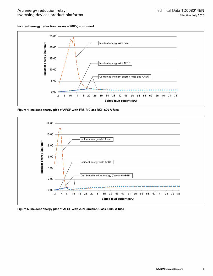
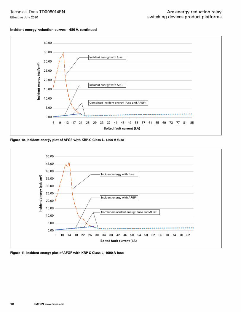
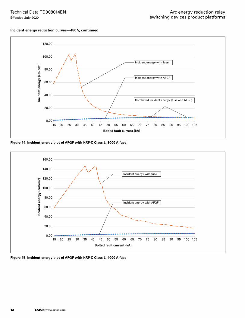
A summary of the process to perform these calculations per IEEE 1584-2018 is described on page 6, and these calculations are summarized in graphical form on page 6–page 13 . The calculations show that as the level of bolted fault current increases, the arc energy decreases after 5–10 times the fuse current rating is reached . The arc energy at the higher bolted fault current is lower due to the fuse clearing faster as the current increases .
For low arcing currents and specific fuse types, the arc energy may be 20 times higher that of high arcing currents because the time for the fuse to clear is longer .
Examples of incidents leading to low arcing currents are:• Dropping hardware or un-insulated tools onto live conductors• Crossing opposite phases of un-insulated sections of probes or tools• Dirt build-up that creates a path between conductors• Overheating leading to insulation breakdown• Poor maintenance that leads to insulation breakdown• Water ingress between phases
Examples of incidents leading to high arcing currents are:• Crossed phases during conductor installation• Fault in overcurrent device (maintenance or application)
System diagramFault location
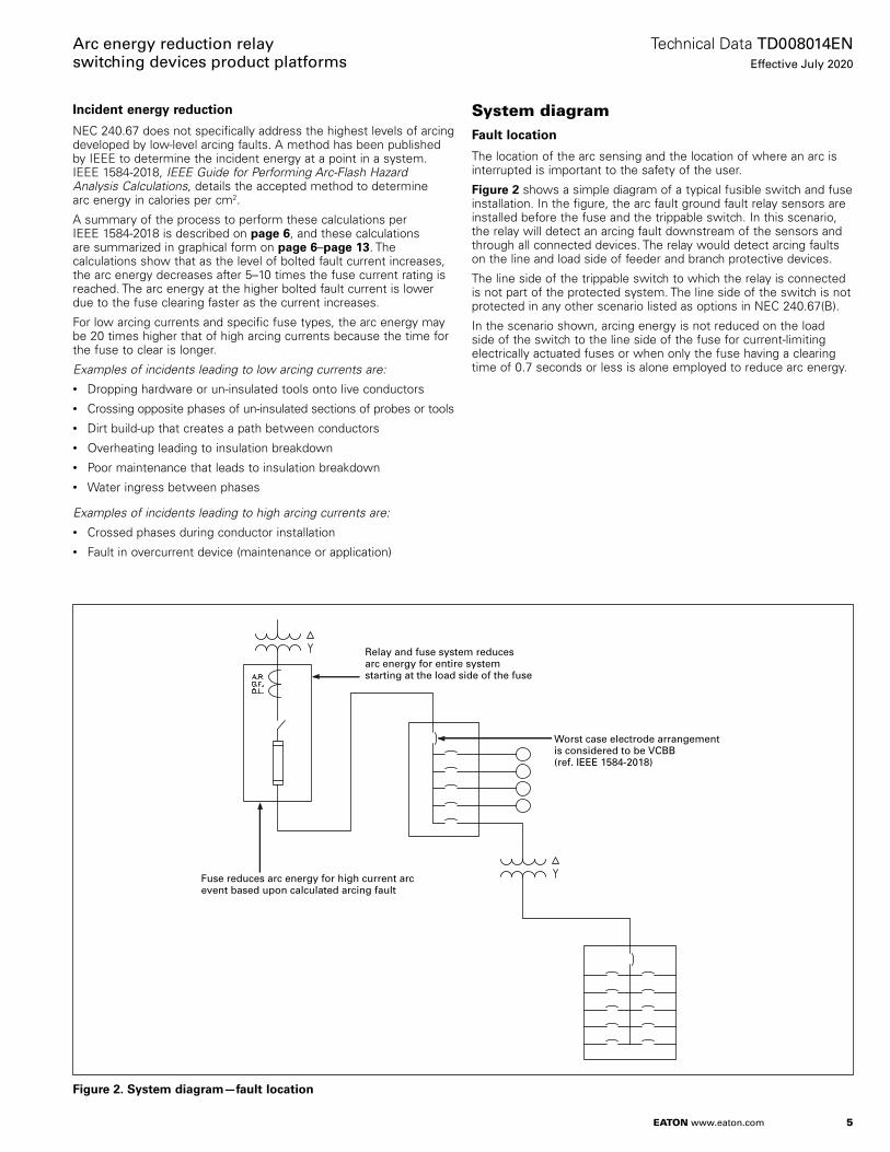
The location of the arc sensing and the location of where an arc is interrupted is important to the safety of the user .
Figure 2 shows a simple diagram of a typical fusible switch and fuse installation . In the figure, the arc fault ground fault relay sensors are installed before the fuse and the trippable switch . In this scenario, the relay will detect an arcing fault downstream of the sensors and through all connected devices . The relay would detect arcing faults on the line and load side of feeder and branch protective devices .
The line side of the trippable switch to which the relay is connected is not part of the protected system . The line side of the switch is not protected in any other scenario listed as options in NEC 240 .67(B) .
In the scenario shown, arcing energy is not reduced on the load side of the switch to the line side of the fuse for current-limiting electrically actuated fuses or when only the fuse having a clearing time of 0 .7 seconds or less is alone employed to reduce arc energy .
Fuse reduces arc energy for high current arc event based upon calculated arcing fault
Relay and fuse system reducesarc energy for entire system starting at the load side of the fuse
Worst case electrode arrangementis considered to be VCBB (ref. IEEE 1584-2018)
Figure 2. System diagram—fault location
6
Technical Data TD008014ENEffective July 2020
Arc energy reduction relay switching devices product platforms
EATON www.eaton.com
Incident energy calculation descriptionThe calculation of the arc energy enables the system user to predict arc flash incident energy to which employees could be exposed during operations and maintenance work . Incident thermal energy estimation helps to predict appropriate protection for employees (PPE) .
Arc flash hazard calculation guideline
The following is a summary of the method used to calculate the arc energy for various fuse, voltage, and current ratings using IEEE 1584-2018, IEEE Guide for Performing Arc-Flash Hazard Analysis Calculations .• Incident energy calculations is divided into two parts based on
system open-circuit voltage• 208 V to 600 V a
• 600 V to 15 kV
• The actual equipment conductor orientation and arrangement that most closely resembles the five electrode arrangement should be established:• VCB
• VCBB b
• HCB
• VOA
• HOA
• The IEEE guide specifies a two-step (average and interpolated) process for arc current, incident energy, and arc flash boundary to determine final values
• Enclosure (box) size correction factors are applied to adjust the results
aOnly 208 and 480 Vac applications considered in the following arc incident energy calculations.bElectrode configuration VCBB is considered worst case in typical downstream devices connected
to switching devices.
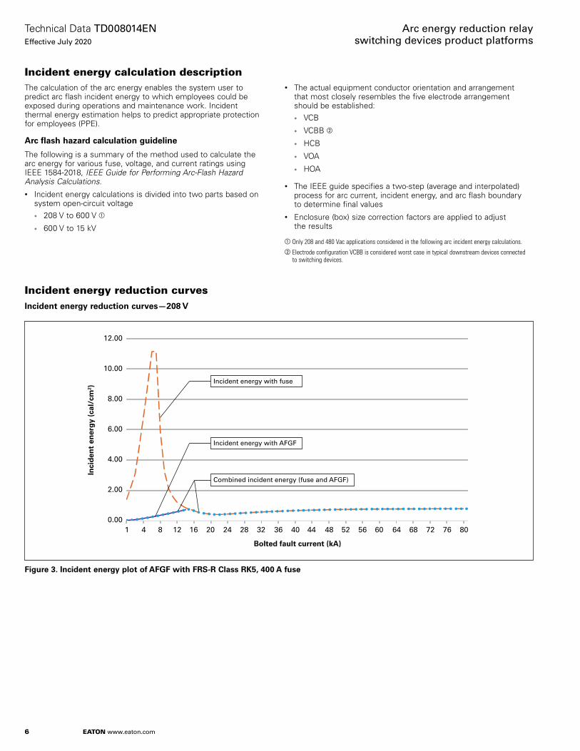
Incident energy reduction curvesIncident energy reduction curves—208 V
Inci
den
t en
erg
y (c
al/c
m2 )
12.00
10.00
8.00
6.00
4.00
2.00
0.001
Bolted fault current (kA)
4 8 12 16 20 24 28 32 36 40 44 48 52 56 60 64 68 72 76 80
Incident energy with fuse
Incident energy with AFGF
Combined incident energy (fuse and AFGF)
Figure 3. Incident energy plot of AFGF with FRS-R Class RK5, 400 A fuse
7
Technical Data TD008014ENEffective July 2020
Arc energy reduction relay switching devices product platforms
EATON www.eaton.com
Incident energy reduction curves—208 V, continued
Inci
den
t en
erg
y (c
al/c
m2 )
25.00
20.00
15.00
10.00
5.00
0.002
Bolted fault current (kA)
6 10 14 18 22 26 30 34 38 42 46 50 54 58 62 66 70 74 78
Incident energy with fuse
Incident energy with AFGF
Combined incident energy (fuse and AFGF)
Figure 4. Incident energy plot of AFGF with FRS-R Class RK5, 600 A fuse
Inci
den
t en
erg
y (c
al/c
m2 )
12.00
10.00
8.00
6.00
4.00
2.00
0.003
Bolted fault current (kA)
7 11 15 19 23 27 31 35 39 43 47 51 55 59 63 67 71 75 79 83
Incident energy with fuse
Incident energy with AFGF
Combined incident energy (fuse and AFGF)
Figure 5. Incident energy plot of AFGF with JJN Limitron Class T, 800 A fuse

8
Technical Data TD008014ENEffective July 2020
Arc energy reduction relay switching devices product platforms
EATON www.eaton.com
Incident energy reduction curves—208 V, continued
Inci
den
t en
erg
y (c
al/c
m2 )
25.00
20.00
15.00
10.00
5.00
0.005
Bolted fault current (kA)
9 13 17 21 25 29 33 37 41 45 49 53 61 65 69 73 77 81 85
Incident energy with fuse
Incident energy with AFGF
Combined incident energy (fuse and AFGF)
Figure 6. Incident energy plot of AFGF with JJN Limitron Class T, 1200 A fuse
Incident energy reduction curves—480 V
Inci
den
t en
erg
y (c
al/c
m2 )
12.00
10.00
8.00
6.00
4.00
2.00
0.001
Bolted fault current (kA)
3 7 11 15 19 23 27 31 35 39 43 47 51 55 59 63 67 71 75 79
Incident energy with fuse
Incident energy with AFGF
Combined incident energy (fuse and AFGF)
Figure 7. Incident energy plot of AFGF with FRS-R Class RK5, 400 A fuse

9
Technical Data TD008014ENEffective July 2020
Arc energy reduction relay switching devices product platforms
EATON www.eaton.com
Incident energy reduction curves—480 V, continued
Inci
den
t en
erg
y (c
al/c
m2 )
25.00
20.00
15.00
10.00
5.00
0.001
Bolted fault current (kA)
3 7 11 15 19 23 27 31 35 39 43 47 51 55 59 63 67 71 75 79
Incident energy with fuse
Incident energy with AFGF
Combined incident energy (fuse and AFGF)
Figure 8. Incident energy plot of AFGF with FRS-R Class RK5, 600 A fuse
Inci
den
t en
erg
y (c
al/c
m2 )
30.00
25.00
20.00
15.00
10.00
5.00
0.00
Bolted fault current (kA)
833 7 11 15 19 23 27 31 35 39 43 47 51 55 59 63 67 71 75 79
Incident energy with fuse
Incident energy with AFGF
Combined incident energy (fuse and AFGF)
Figure 9. Incident energy plot of AFGF with KRP-C Class L, 800 A fuse
10
Technical Data TD008014ENEffective July 2020
Arc energy reduction relay switching devices product platforms
EATON www.eaton.com
Incident energy reduction curves—480 V, continued
Inci
den
t en
erg
y (c
al/c
m2 )
40.00
35.00
30.00
25.00
20.00
15.00
10.00
5.00
0.00
5
Bolted fault current (kA)
9 13 17 21 25 29 33 37 41 45 49 53 57 61 65 69 73 77 81 85
Incident energy with fuse
Incident energy with AFGF
Combined incident energy (fuse and AFGF)
Figure 10. Incident energy plot of AFGF with KRP-C Class L, 1200 A fuse
Inci
den
t en
erg
y (c
al/c
m2 )
50.00
45.00
40.00
35.00
30.00
25.00
20.00
15.00
10.00
5.00
0.006
Bolted fault current (kA)
10 14 18 22 26 30 34 38 42 46 50 54 58 62 66 70 74 78 82
Incident energy with fuse
Incident energy with AFGF
Combined incident energy (fuse and AFGF)
Figure 11. Incident energy plot of AFGF with KRP-C Class L, 1600 A fuse

11
Technical Data TD008014ENEffective July 2020
Arc energy reduction relay switching devices product platforms
EATON www.eaton.com
Incident energy reduction curves—480 V, continued
Inci
den
t en
erg
y (c
al/c
m2 )
70.00
60.00
50.00
40.00
30.00
20.00
10.00
0.008
Bolted fault current (kA)
12 16 20 24 28 32 36 40 44 48 52 56 60 64 68 72 76 80 84
Incident energy with fuse
Incident energy with AFGF
Combined incident energy (fuse and AFGF)
Figure 12. Incident energy plot of AFGF with KRP-C Class L, 2000 A fuse
Inci
den
t en
erg
y (c
al/c
m2 )
80.00
70.00
60.00
50.00
40.00
30.00
20.00
10.00
0.0010
Bolted fault current (kA)
15 20 25 30 35 40 45 50 55 60 65 70 75 80 85
Incident energy with fuse
Incident energy with AFGF
Combined incident energy (fuse and AFGF)
Figure 13. Incident energy plot of AFGF with KRP-C Class L, 2500 A fuse
12
Technical Data TD008014ENEffective July 2020
Arc energy reduction relay switching devices product platforms
EATON www.eaton.com
Incident energy reduction curves—480 V, continued
Inci
den
t en
erg
y (c
al/c
m2 )
120.00
100.00
80.00
60.00
40.00
20.00
0.0015
Bolted fault current (kA)
20 25 30 35 40 45 50 55 60 65 70 75 80 85 90 95 100 105
Incident energy with fuse
Incident energy with AFGF
Combined incident energy (fuse and AFGF)
Figure 14. Incident energy plot of AFGF with KRP-C Class L, 3000 A fuse
Inci
den
t en
erg
y (c
al/c
m2 )
160.00
140.00
120.00
100.00
80.00
60.00
40.00
20.00
0.0015
Bolted fault current (kA)
20 25 30 35 40 45 50 55 60 65 70 75 80 85 90 95 100 105
Incident energy with fuse
Incident energy with AFGF
Figure 15. Incident energy plot of AFGF with KRP-C Class L, 4000 A fuse
13
Technical Data TD008014ENEffective July 2020
Arc energy reduction relay switching devices product platforms
EATON www.eaton.com
Incident energy reduction curves—480 V, continued
Inci
den
t en
erg
y (c
al/c
m2 )
250.00
200.00
150.00
100.00
50.00
0.0020
Bolted fault current (kA)
25 30 35 40 45 50 55 60 65 70 75 80 85 90 95 100 105
Incident energy with fuse
Incident energy with AFGF
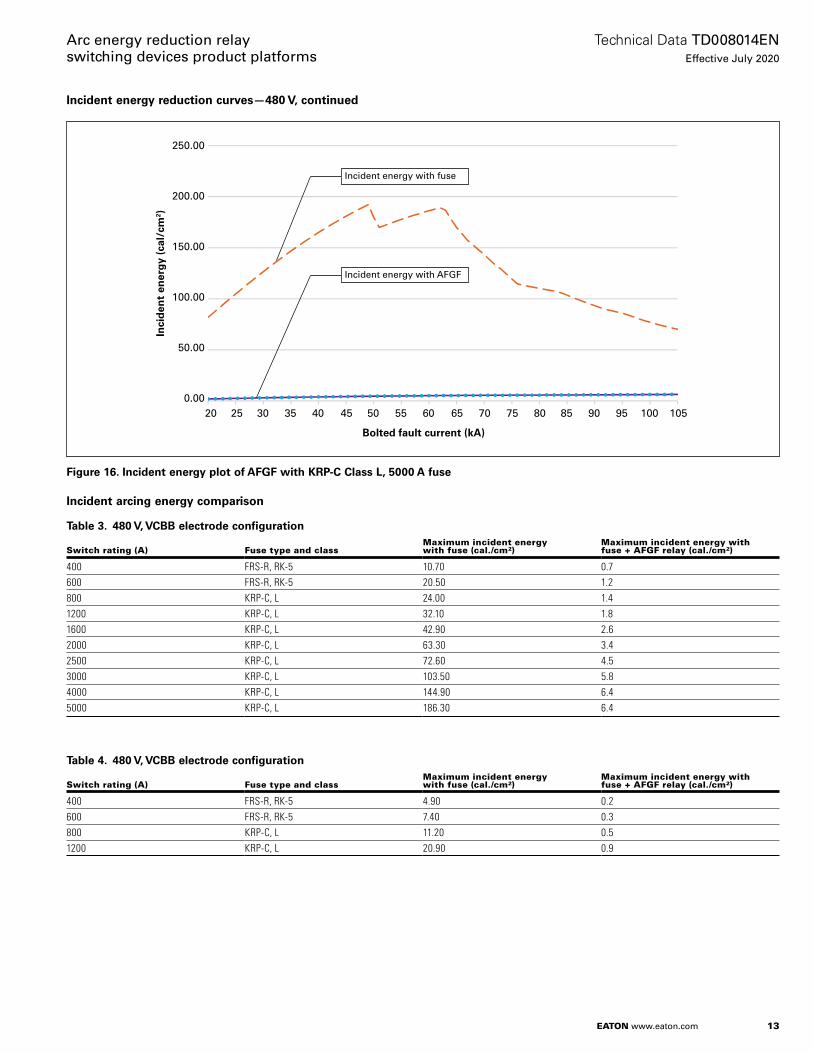
Figure 16. Incident energy plot of AFGF with KRP-C Class L, 5000 A fuse
Incident arcing energy comparison
Table 3. 480 V, VCBB electrode configuration
Switch rating (A) Fuse type and classMaximum incident energy with fuse (cal./cm2)
Maximum incident energy with fuse + AFGF relay (cal./cm2)
400 FRS-R, RK-5 10.70 0.7600 FRS-R, RK-5 20.50 1.2800 KRP-C, L 24.00 1.41200 KRP-C, L 32.10 1.81600 KRP-C, L 42.90 2.62000 KRP-C, L 63.30 3.42500 KRP-C, L 72.60 4.53000 KRP-C, L 103.50 5.84000 KRP-C, L 144.90 6.45000 KRP-C, L 186.30 6.4
Table 4. 480 V, VCBB electrode configuration
Switch rating (A) Fuse type and classMaximum incident energy with fuse (cal./cm2)
Maximum incident energy with fuse + AFGF relay (cal./cm2)
400 FRS-R, RK-5 4.90 0.2600 FRS-R, RK-5 7.40 0.3800 KRP-C, L 11.20 0.51200 KRP-C, L 20.90 0.9
14
Technical Data TD008014ENEffective July 2020
Arc energy reduction relay switching devices product platforms
EATON www.eaton.com
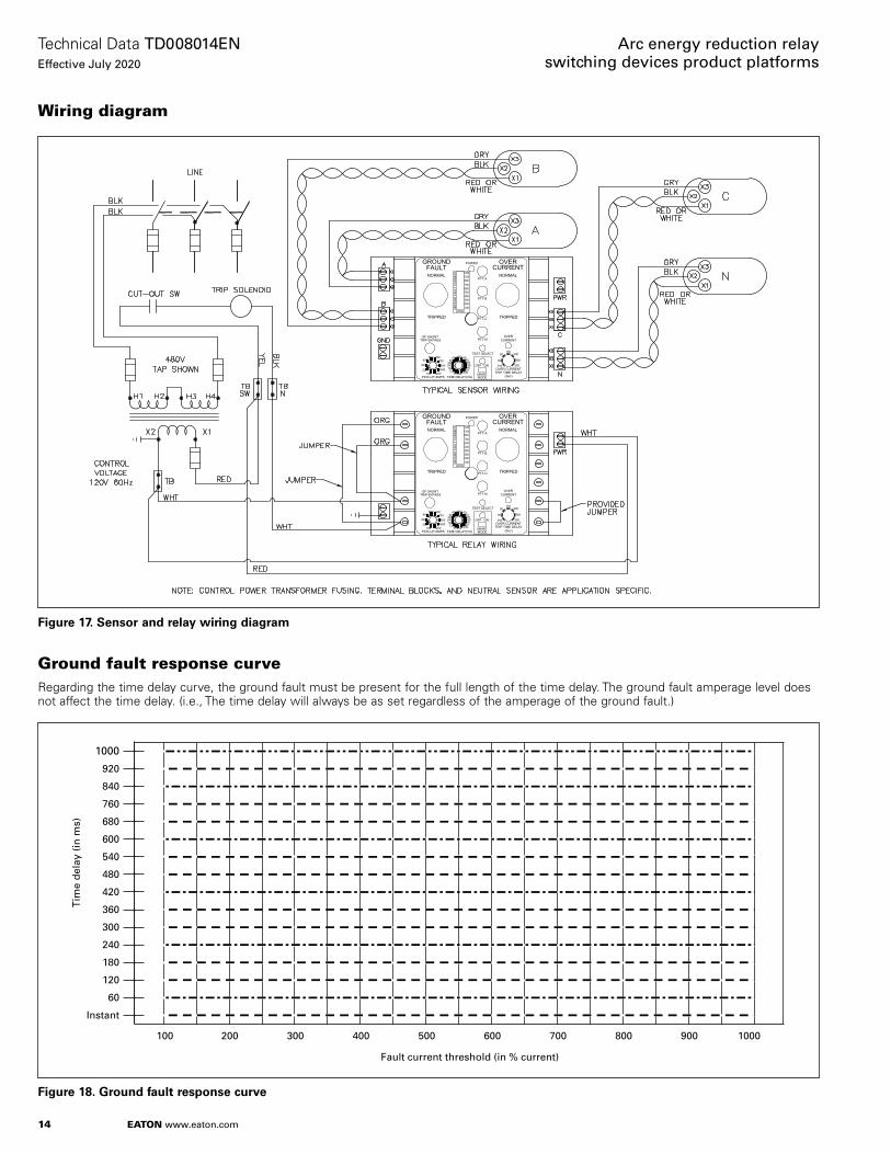
Wiring diagram
OVER CURRENT
(Sec)
NORMAL
TRIPPED
GF SHUNTTRIP BYPASS
PICK-UP AMPS100
200
300
400
12001000
800700
600500
TIME DELAY60
120180240300360
420480540600680760840
9201000Inst
10020030040050060070080010001200
GROUND
(Amp)
(ms)
POWER OVER
NORMAL
TRIPPED
GR
OU
ND
FA
ULT
CU
RR
EN
T
MAINT.
OFF ON
MODE
PTT-N
PTT-C
PTT-B
PTT-A
CURRENTOVER
TRIP TIME DELAY
150200
260
300Inst.
30
90
FAULT CURRENT
TEST SELECT
Figure 17. Sensor and relay wiring diagram
Ground fault response curveRegarding the time delay curve, the ground fault must be present for the full length of the time delay . The ground fault amperage level does not affect the time delay . (i .e ., The time delay will always be as set regardless of the amperage of the ground fault .)
760
Tim
e d
elay
(in
ms)
1000
920
840
Instant
680
600
540
480
420
360
300
240
180
120
60
100 200 300 400 500 600
Fault current threshold (in % current)
700 800 900 1000
Figure 18. Ground fault response curve

15
Technical Data TD008014ENEffective July 2020
Arc energy reduction relay switching devices product platforms
EATON www.eaton.com
Zone interlockGround fault relay zone interlock
Electromagnetic Industries GFPV Relay
Electromagnetic Industries GFP Relay
Electromagnetic Industries GFPV Relay
Electromagnetic Industries AFGF Relay
Electromagnetic Industries AFGF Relay
Electromagnetic Industries GFP Relay
Figure 19. Ground fault relay zone interlock
Operation
Example
When a branch relay detects a ground fault, the associated feeders and main relays will detect it at the same time . The time delay will begin on all the relays’; however, the branch unit will send a “No Trip” signal to the upstream feeder relay . The feeder relay will send a “No Trip” signal to the main relay . Once the branch relay time delay has expired, the unit will trip and remove the “No Trip” signal from the upstream units . If the ground fault is still present and the time delay has expired, the feeder unit will trip and remove the “No Trip” signal from the main relay . If the ground fault is still present, and the main relay’s time delay has expired, the main relay will trip .
ote: N All zone interlock wiring must be wire size 16–20 AWG twisted pair . A limit of 10 upstream units are to be used to a single output .
16
Technical Data TD008014ENEffective July 2020
Arc energy reduction relay switching devices product platforms
EATON www.eaton.com
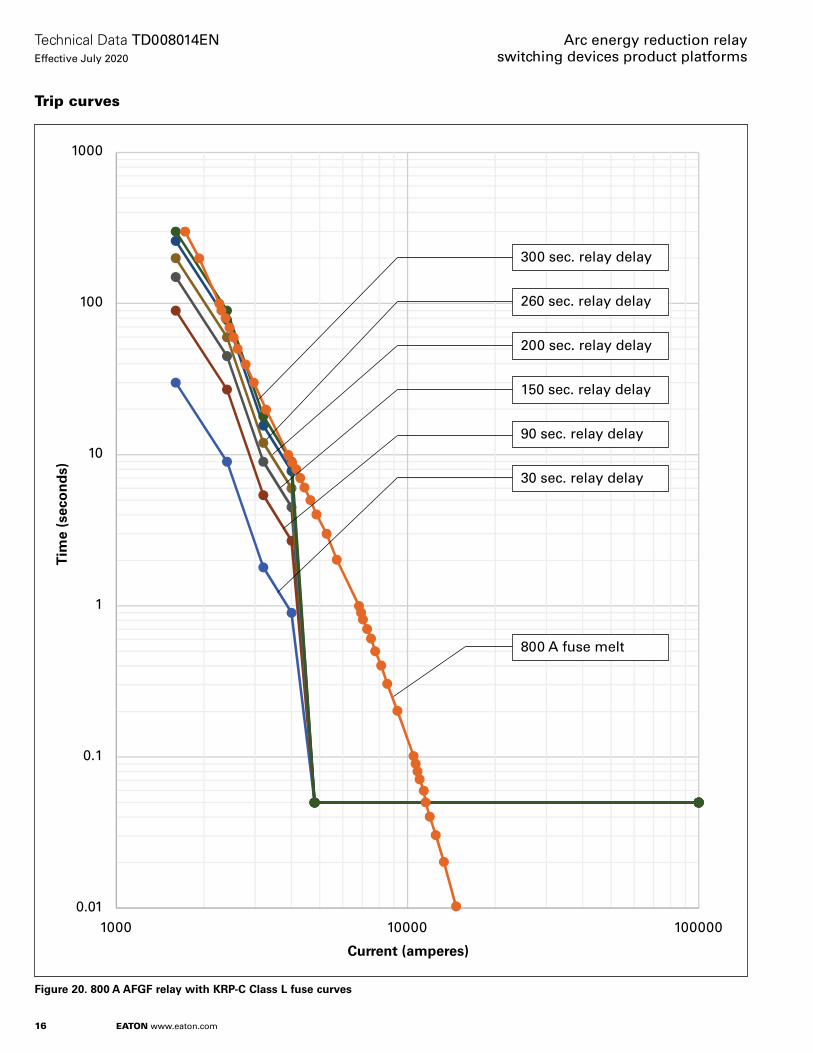
Trip curves
1000
100
10
1
0.1
0.011000 10000 100000
Current (amperes)
Tim
e (s
eco
nd
s)
300 sec. relay delay
260 sec. relay delay
200 sec. relay delay
150 sec. relay delay
90 sec. relay delay
30 sec. relay delay
800 A fuse melt
Figure 20. 800 A AFGF relay with KRP-C Class L fuse curves

17
Technical Data TD008014ENEffective July 2020
Arc energy reduction relay switching devices product platforms
EATON www.eaton.com
1000
100
10
1
0.1
0.011000 10000 100000
Current (amperes)
Tim
e (s
eco
nd
s)
300 sec. relay delay
260 sec. relay delay
200 sec. relay delay
150 sec. relay delay
90 sec. relay delay
30 sec. relay delay
1200 A fuse melt
Figure 21. 1200 A AFGF relay with KRP-C Class L fuse curves

18
Technical Data TD008014ENEffective July 2020
Arc energy reduction relay switching devices product platforms
EATON www.eaton.com
1000
100
10
1
0.1
0.011000 10000 100000
Current (amperes)
Tim
e (s
eco
nd
s)
300 sec. relay delay
260 sec. relay delay
200 sec. relay delay
150 sec. relay delay
90 sec. relay delay
30 sec. relay delay
1600 A fuse melt
Figure 22. 1600 A AFGF relay with KRP-C Class L fuse curves

19
Technical Data TD008014ENEffective July 2020
Arc energy reduction relay switching devices product platforms
EATON www.eaton.com
1000
100
10
1
0.1
0.011000 10000 100000
Current (amperes)
Tim
e (s
eco
nd
s)
300 sec. relay delay
260 sec. relay delay
200 sec. relay delay
150 sec. relay delay
90 sec. relay delay
30 sec. relay delay
2000 A fuse melt
Figure 23. 2000 A AFGF relay with KRP-C Class L fuse curves

20
Technical Data TD008014ENEffective July 2020
Arc energy reduction relay switching devices product platforms
EATON www.eaton.com
1000
100
10
1
0.1
0.011000 10000 100000
Current (amperes)
Tim
e (s
eco
nd
s)
300 sec. relay delay
260 sec. relay delay
200 sec. relay delay
150 sec. relay delay
90 sec. relay delay
30 sec. relay delay
2500 A fuse melt
Figure 24. 2500 A AFGF relay with KRP-C Class L fuse curves

21
Technical Data TD008014ENEffective July 2020
Arc energy reduction relay switching devices product platforms
EATON www.eaton.com
1000
100
10
1
0.1
0.011000 10000 100000
Current (amperes)
Tim
e (s
eco
nd
s)
300 sec. relay delay
260 sec. relay delay
200 sec. relay delay
150 sec. relay delay
90 sec. relay delay
30 sec. relay delay
3000 A fuse melt
Figure 25. 3000 A AFGF relay with KRP-C Class L fuse curves
22
Technical Data TD008014ENEffective July 2020
Arc energy reduction relay switching devices product platforms
EATON www.eaton.com
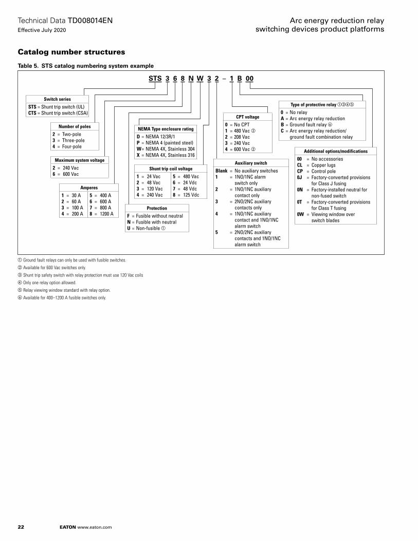
Catalog number structures
Table 5. STS catalog numbering system example
aGround fault relays can only be used with fusible switches.bAvailable for 600 Vac switches only.cShunt trip safety switch with relay protection must use 120 Vac coilsdOnly one relay option allowed.eRelay viewing window standard with relay option.fAvailable for 400–1200 A fusible switches only.
STS 3 6 8 N W 3 2 – 1 B 00
Switch series
STS = Shunt trip switch (UL)CTS = Shunt trip switch (CSA)
Additional options/modifications
00 = No accessoriesCL = Copper lugsCP = Control pole 0J = Factory-converted provisions
for Class J fusing0N = Factory-installed neutral for
non-fused switch0T = Factory-converted provisions
for Class T fusing 0W = Viewing window over
switch blades
Maximum system voltage
2 = 240 Vac6 = 600 Vac
Number of poles
2 = Two-pole3 = Three-pole4 = Four-pole
Amperes
1 = 30 A2 = 60 A3 = 100 A4 = 200 A
5 = 400 A6 = 600 A7 = 800 A8 = 1200 A
Protection
F = Fusible without neutralN = Fusible with neutralU = Non-fusible a
Auxiliary switch
Blank = No auxiliary switches1 = 1NO/1NC alarm switch only2 = 1NO/1NC auxiliary contact only 3 = 2NO/2NC auxiliary contacts only4 = 1NO/1NC auxiliary contact and 1NO/1NC alarm switch5 = 2NO/2NC auxiliary contacts and 1NO/1NC alarm switch
NEMA Type enclosure rating
D = NEMA 12/3R/1P = NEMA 4 (painted steel)W = NEMA 4X, Stainless 304X = NEMA 4X, Stainless 316
Shunt trip coil voltage
1 = 24 Vac2 = 48 Vac3 = 120 Vac4 = 240 Vac
5 = 480 Vac6 = 24 Vdc7 = 48 Vdc8 = 125 Vdc
CPT voltage
0 = No CPT1 = 480 Vac b2 = 208 Vac3 = 240 Vac4 = 600 Vac b
Type of protective relay acde
0 = No relayA = Arc energy relay reductionB = Ground fault relay fC = Arc energy relay reduction/
ground fault combination relay
23
Technical Data TD008014ENEffective July 2020
Arc energy reduction relay switching devices product platforms
EATON www.eaton.com
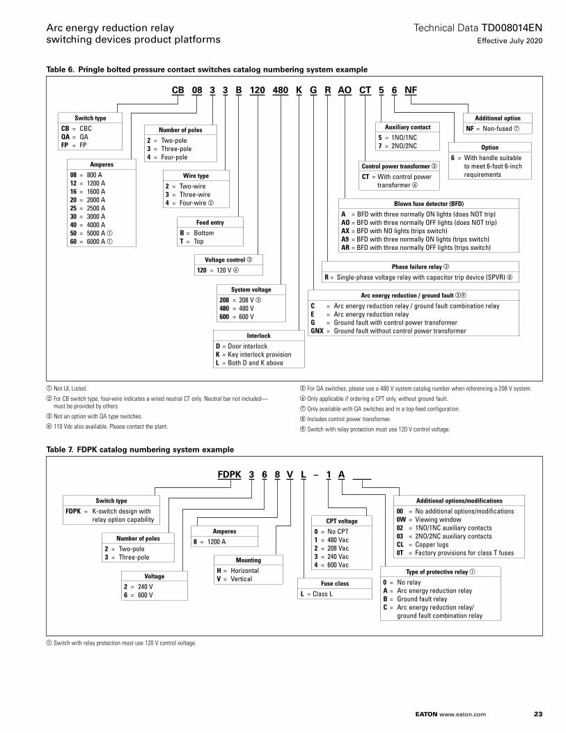
Table 6. Pringle bolted pressure contact switches catalog numbering system example
aNot UL Listed. bFor CB switch type, four-wire indicates a wired neutral CT only. Neutral bar not included—
must be provided by others.cNot an option with QA type switches. d110 Vdc also available. Please contact the plant.
eFor QA switches, please use a 480 V system catalog number when referencing a 208 V system.fOnly applicable if ordering a CPT only, without ground fault.gOnly available with QA switches and in a top-feed configuration.h Includes control power transformer.iSwitch with relay protection must use 120 V control voltage.
Table 7. FDPK catalog numbering system example
aSwitch with relay protection must use 120 V control voltage.
CB 08 3 3 B 120 480 K G R AO CT 5 6 NF
Switch type
CB = CBCQA = QAFP = FP
Amperes
08 = 800 A12 = 1200 A 16 = 1600 A20 = 2000 A25 = 2500 A30 = 3000 A40 = 4000 A50 = 5000 A a60 = 6000 A a
Number of poles
2 = Two-pole3 = Three-pole 4 = Four-pole
Wire type
2 = Two-wire3 = Three-wire 4 = Four-wire b
Additional option
NF = Non-fused gAuxiliary contact
5 = 1NO/1NC7 = 2NO/2NC
Control power transformer c
CT = With control power transformer f
Blown fuse detector (BFD)
A = BFD with three normally ON lights (does NOT trip) AO = BFD with three normally OFF lights (does NOT trip)AX = BFD with NO lights (trips switch)A9 = BFD with three normally ON lights (trips switch)AR = BFD with three normally OFF lights (trips switch)
Phase failure relay c
R = Single-phase voltage relay with capacitor trip device (SPVR) h
Arc energy reduction / ground fault ci
C = Arc energy reduction relay / ground fault combination relayE = Arc energy reduction relayG = Ground fault with control power transformerGNX = Ground fault without control power transformer
Feed entry
B = BottomT = Top
Voltage control c
120 = 120 V d
System voltage
208 = 208 V e480 = 480 V600 = 600 V
Interlock
D = Door interlockK = Key interlock provisionL = Both D and K above
Option
6 = With handle suitable to meet 6-foot 6-inch requirements
FDPK 3 6 8 V L – 1 A ____
Number of poles
2 = Two-pole3 = Three-pole
Voltage
2 = 240 V6 = 600 V
Type of protective relay a
0 = No relay A = Arc energy reduction relay B = Ground fault relayC = Arc energy reduction relay/
ground fault combination relay
Amperes
8 = 1200 A
Mounting
H = HorizontalV = Vertical
Fuse class
L = Class L
CPT voltage
0 = No CPT1 = 480 Vac2 = 208 Vac3 = 240 Vac4 = 600 Vac
Additional options/modifications
00 = No additional options/modifications 0W = Viewing window 02 = 1NO/1NC auxiliary contacts03 = 2NO/2NC auxiliary contactsCL = Copper lugs0T = Factory provisions for class T fuses
Switch type
FDPK = K-switch design with relay option capability
Eaton1000 Eaton BoulevardCleveland, OH 44122United StatesEaton .com
© 2020 EatonAll Rights ReservedPrinted in USAPublication No . TD008014EN / Z23805July 2020
Eaton is a registered trademark.
All other trademarks are property of their respective owners.
Arc energy reduction relay switching devices product platforms
Technical Data TD008014ENEffective July 2020
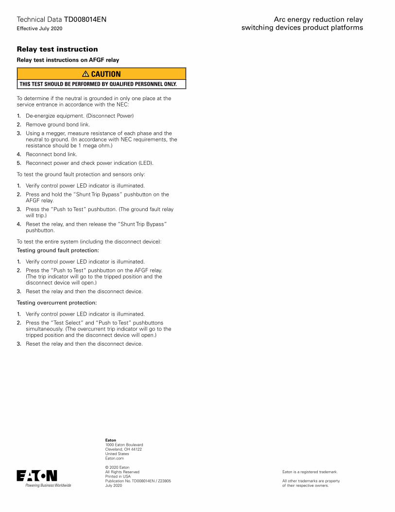
Relay test instructionRelay test instructions on AFGF relay
CAUTIONTHIS TEST SHOULD BE PERFORMED BY QUALIFIED PERSONNEL ONLY.
To determine if the neutral is grounded in only one place at the service entrance in accordance with the NEC:
1. De-energize equipment . (Disconnect Power)
2. Remove ground bond link .
3. Using a megger, measure resistance of each phase and the neutral to ground . (In accordance with NEC requirements, the resistance should be 1 mega ohm .)
4. Reconnect bond link .
5. Reconnect power and check power indication (LED) .
To test the ground fault protection and sensors only:
1. Verify control power LED indicator is illuminated .
2. Press and hold the “Shunt Trip Bypass” pushbutton on the AFGF relay .
3. Press the “Push to Test” pushbutton . (The ground fault relay will trip .)
4. Reset the relay, and then release the “Shunt Trip Bypass” pushbutton .
To test the entire system (including the disconnect device):
Testing ground fault protection:
1. Verify control power LED indicator is illuminated .
2. Press the “Push to Test” pushbutton on the AFGF relay . (The trip indicator will go to the tripped position and the disconnect device will open .)
3. Reset the relay and then the disconnect device .
Testing overcurrent protection:
1. Verify control power LED indicator is illuminated .
2. Press the “Test Select” and “Push to Test” pushbuttons simultaneously . (The overcurrent trip indicator will go to the tripped position and the disconnect device will open .)
3. Reset the relay and then the disconnect device .