Embed Size (px)
Citation preview
8/14/2019 AR15 Neutral
http://slidepdf.com/reader/full/ar15-neutral 1/2
T E C H N I C A L I N F O R M A T I O N AR_15
Modal-Tuning improves impact testingRichard W. Lally
Structural Testing Product Manager
PCB Piezotronics, Inc.
Depew, New York
Abstract:
The natural resonances of conventional impact hammer structures were determined to be the cause of spurious glitches in frequency responsefunction (FRF) measurements made during impact testing. By modaltuning, or tuning the mode shapes of the hammer structure, an impact
hammer was developed which functions and feels better.
lntroduction:
As many as ten years ago, the rst production hammer was available after its development at the University of Cincinnati. It was a simple ham-
mer structure with a force sensor installed on the head.
It was initially used at low frequencies to conveniently excite a test object‘s resonances for modal testing. As impact testing became more pro-
minent and widely used, the hammers were used over the entire frequency range they were capable of exciting. In early testing, it was noticed
that the otherwise smooth roll-off spectrum of the hammer impact contained glitches in the 600 Hz and 1600 Hz region (1). These appeared as
glitches in the corresponding FRF measurements computed from this data, The glitches did not represent behavior of the test object.
In general, these glitches were we11 known and repeatable. They were regarded as unavoidable natural behavior of the hammer. In FRF
measurements, they were either ignored or a complete frequency response calibration curve was stored to be subtracted from the measured
FRF‘s. This calibration procedure measured and removed the glitches hom the FRF‘s. At this point in the hammer evolution (approx. 1983), the
problem of the glitches was identied and a solution devised.
1
Cause of The Glitches:
Force sensors, as with a11 sensors, are imperfect devices. Along with
their sensitivity to force, they have same degree of motion sensitivity.
It was suspected that this sensitivity to motion was sensing the natu-
ral resonances of the hammer structure excited after impact. This re-
sulted in the glitches in the force spectrum and corresponding FRF.
The test needed to verify this was to perform a modal survey on the
hammer itself to obtain frequency values and mode shapes. This was
accomplished using a miniature piezoelectric accelerometer, the
force sensor on the impact hammer and a two channel FFT analy-
zer. The accelerometer was moved along the hammer handle in theaxial direction to the hammer head. The force sensor was left on the
hammer head and the: face was struck against a convenient mass to
supply the input force.
Just as suspected, the frequencies of the rst two bending modes
matched the two prominent glitches in the hammers force spectrum
[2]. From this, it was conrmed that motion sensitivity of the force
sensor, which was amplied by an impact tip, allowed the natural re-
sonances of the impact hammer to contaminate data. With the prob-
lem dened, solutions were investigated.
First Attempts:
Conventional techniques that involved changes in mass, stiffness and
damping were attempted rst. Stiffer materials used for the handle
on1y shifted the resonances to higher values. Constrained-layer
damping reduced the magnitude of the glitches, but did not eliminate
them. Changes in the length of the hammer head and handle produ-
ced an awkward feeling instrument along with little improvement in
behavior.
Reduction in motion sensitivity of the force sensor by reducing im-
pact tip mass helped reduce the glitches, but adversely affected the
repeatability of force measurements.
The Solution::
If excited, any mode of vibration that resulted in axial, linear motion
of the hammer head ‚would contaminate data with a glitch. This ob-
servation was the key to the solution. If each mode shape could be
modied (modal-tuned) so that a node existed at the hammer head,
then there would be no motion sensed.
This was achieved by two means. The total hammer mass was re-distributed leaving the head much heavier than the handle. Then, a
soft neoprene grip was used to provide damping and isolation of the
operator‘s hand.
Figure 1: Glitches in force spectrum
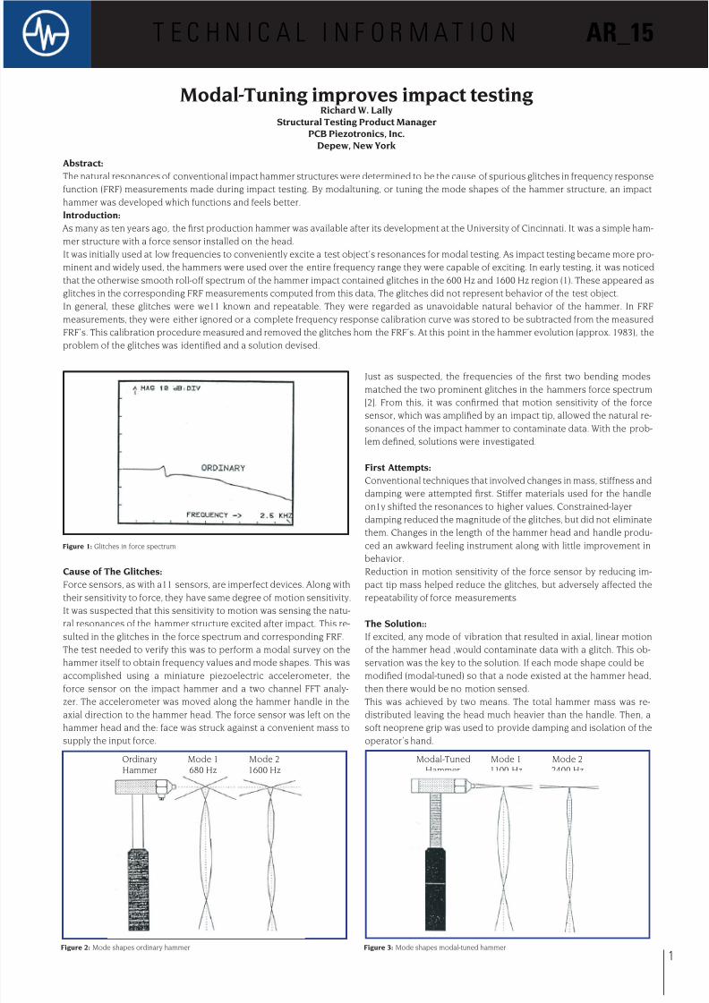
Figure 3: Mode shapes modal-tuned hammerFigure 2: Mode shapes ordinary hammer
Modal-Tuned
Hammer
Ordinary
Hammer
Mode 2
2400 Hz
Mode 2
1600 Hz
Mode 1
1100 Hz
Mode 1
680 Hz
8/14/2019 AR15 Neutral
http://slidepdf.com/reader/full/ar15-neutral 2/2
Chosen for its lightweight and strength, a composite graphite bar was
used for the handle. Custom molded soft neoprene foam was used for
the grip because of its lightweight, damping and isolation qualities.
A tungsten tuning mass on the head he1ped redistribute mass while
maintaining a „shorter“ prole and even balance. Figure (3) illustrates
the modied mode shapes of the modal-tuned hammer. Although fre-
quency values have shifted somewhat, the emphasis of change is in
the mode shape.
Benets of Modal-Tuning:
The head of a modal-tuned hammer experiences little or no motion
during hammer resonance due to its proximity to a node. For the same
reason, the resonances tend not to be excited. If they are excited, the-
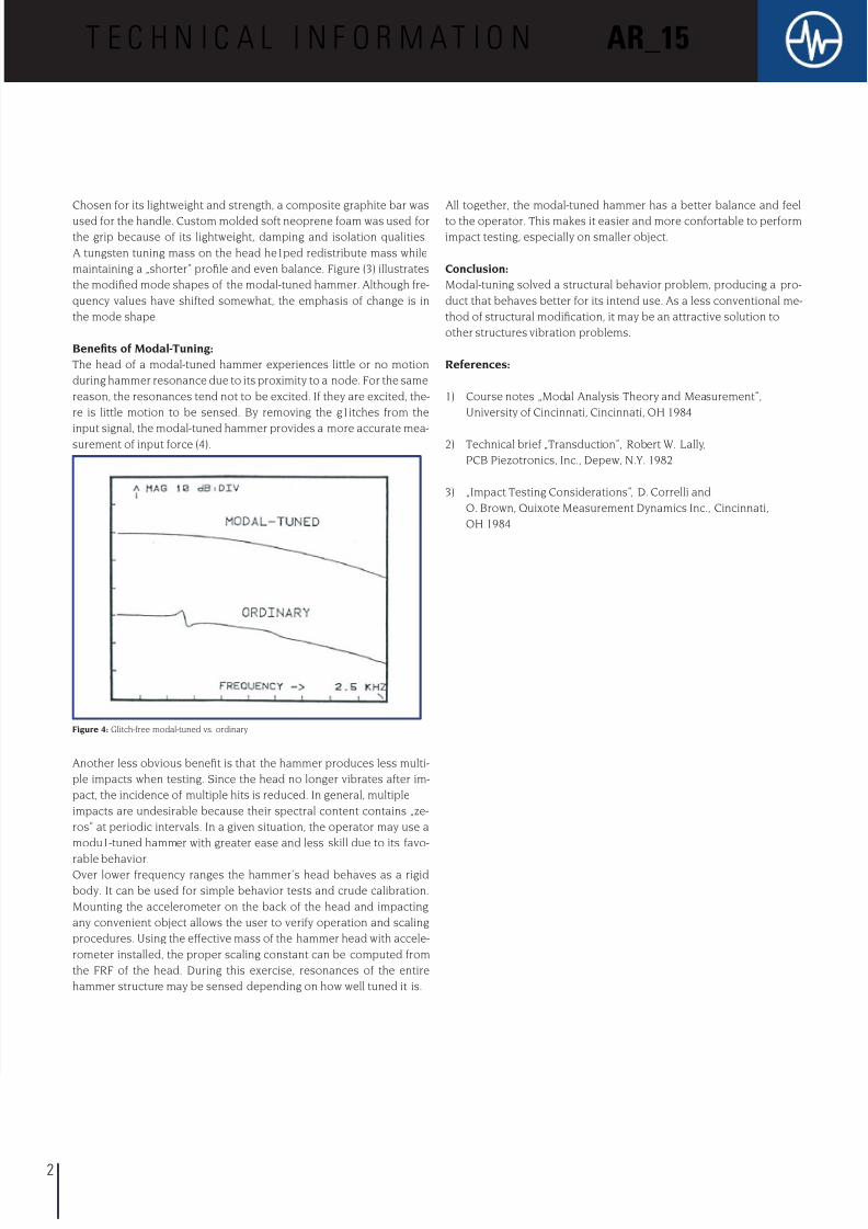
re is little motion to be sensed. By removing the g1itches from the
input signal, the modal-tuned hammer provides a more accurate mea-surement of input force (4).
Another less obvious benet is that the hammer produces less multi-
ple impacts when testing. Since the head no longer vibrates after im-
pact, the incidence of multiple hits is reduced. In general, multiple
impacts are undesirable because their spectral content contains „ze-
ros“ at periodic intervals. In a given situation, the operator may use a
modu1-tuned hammer with greater ease and less skill due to its favo-
rable behavior.Over lower frequency ranges the hammer‘s head behaves as a rigid
body. It can be used for simple behavior tests and crude calibration.
Mounting the accelerometer on the back of the head and impacting
any convenient object allows the user to verify operation and scaling
procedures. Using the effective mass of the hammer head with accele-
rometer installed, the proper scaling constant can be computed from
the FRF of the head. During this exercise, resonances of the entire
hammer structure may be sensed depending on how well tuned it is.
All together, the modal-tuned hammer has a better balance and feel
to the operator. This makes it easier and more confortable to perform
impact testing, especially on smaller object.
Conclusion:
Modal-tuning solved a structural behavior problem, producing a pro-
duct that behaves better for its intend use. As a less conventional me-
thod of structural modication, it may be an attractive solution to
other structures vibration problems.
References:
1) Course notes „Modal Analysis Theory and Measurement“,
University of Cincinnati, Cincinnati, OH 1984
2) Technical brief „Transduction“, Robert W. Lally,
PCB Piezotronics, Inc., Depew, N.Y. 1982
3) „Impact Testing Considerations“, D. Correlli and
O. Brown, Quixote Measurement Dynamics Inc., Cincinnati,
OH 1984
T E C H N I C A L I N F O R M A T I O N AR_15
2
Figure 4: Glitch-free modal-tuned vs. ordinary