Embed Size (px)
Citation preview
24
Warranty
Marshall Electronics warranties to the first consumer that this AR-DM2X-X Audio Monitor will, under normal use, be freefrom defects in workmanship and materials, when received in its original container, for a period of one year from thepurchase date. This warranty is extended to the first consumer only, and proof of purchase is necessary to honor thewarranty. If there is no proof of purchase provided with a warranty claim, Marshall Electronics reserves the right not tohonor the warranty set forth above. Therefore, labor and parts may be charged to the consumer. This warranty does notapply to the product exterior or cosmetics. Misuse, abnormal handling, alterations or modifications in design orconstruction void this warranty. No sales personnel of the seller or any other person is authorized to make any warrantiesother than those described above, or to extend the duration of any warranties on behalf of Marshall Electronics, beyondthe time period described above. Due to constant effort to improve products and product features, specifications maychange without notice.
Marshall Electronics, Inc.1910 East Maple Ave.El Segundo, CA 90245
Tel: (800) 800-6608 / (310) 333-0606 • Fax: 310-333-0688www.LCDRacks.com • [email protected]
v1.0
Marshall Electronics
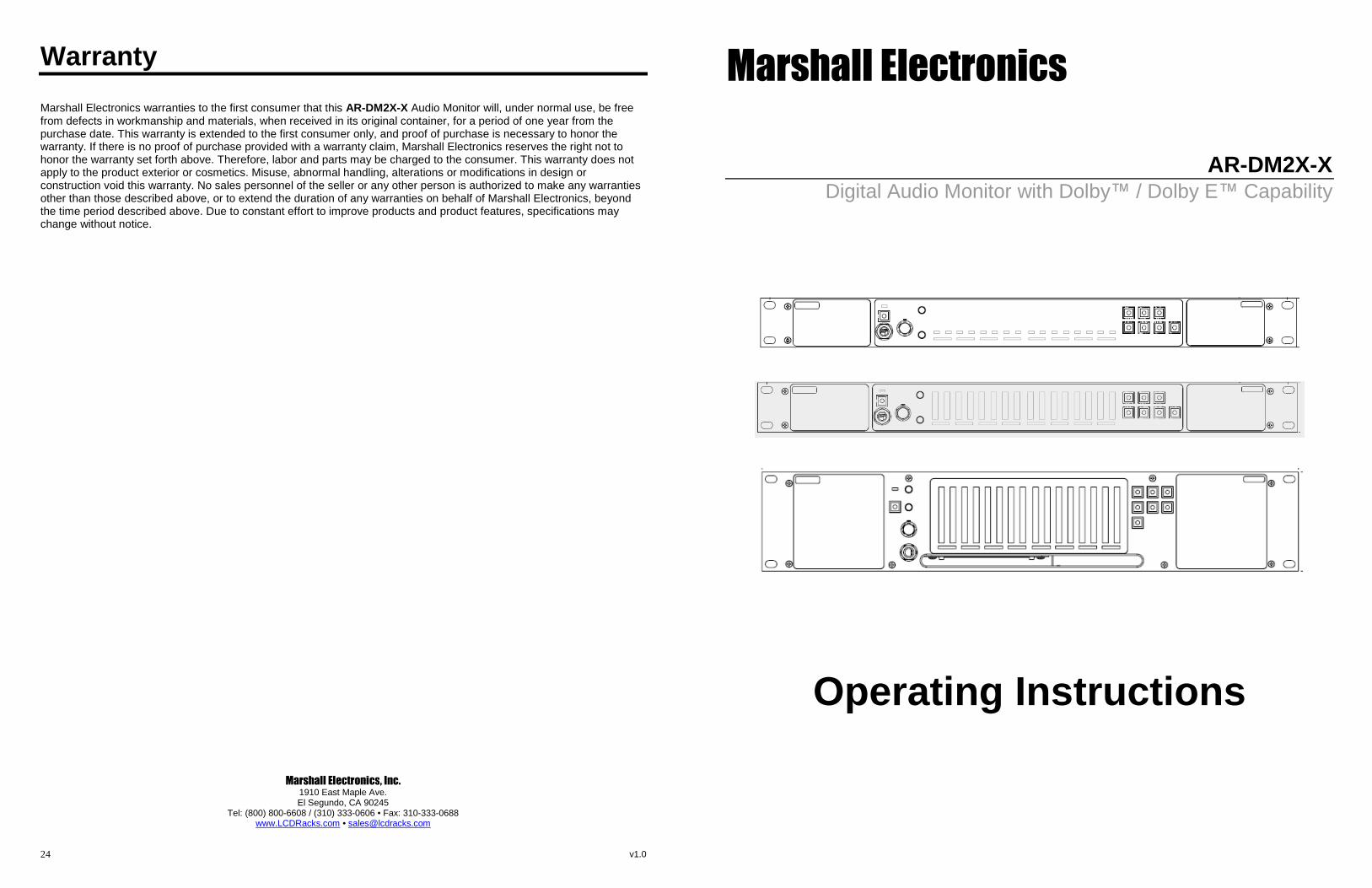
AR-DM2X-XDigital Audio Monitor with Dolby™ / Dolby E™ Capability
Operating Instructions
2 23
Specifications (continued)
Input / Output Modules
■ ARDM-HDSDI Input Module
Inputs: 1 x SDI (75Ω BNC) – 16 channels embedded audio Outputs: 1 x SDI Equalized Loop-Through (75Ω BNC)
SDI Formats: 525i, 625i, 720p, 1080i, 1080pSDI Standards: SMPTE 259M, 292M, 274M, 296M, 260MAudio Coding: PCM, DOLBY E, DOLBY DIGITAL (AC-3)Sample Rates: 44.1kHz, 48kHz
■ ARDM-AES-BNC Input Module
Inputs: 4 x AES/EBU (Unbalanced 75Ω BNC) Outputs: 4 x AES/EBU (Unbalanced 75Ω BNC) Passive Loop-Through
Formats: Professional and Consumer (SPDIF)Audio Coding: PCM, DOLBY E, DOLBY DIGITAL (AC-3)Sample Rates: 44.1kHz, 48kHz
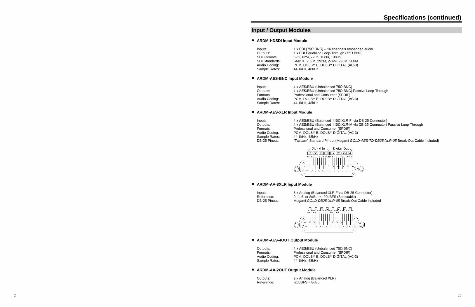
■ ARDM-AES-XLR Input Module
Inputs: 4 x AES/EBU (Balanced 110Ω XLR-F, via DB-25 Connector) Outputs: 4 x AES/EBU (Balanced 110Ω XLR-M via DB-25 Connector) Passive Loop-Through
Formats: Professional and Consumer (SPDIF)Audio Coding: PCM, DOLBY E, DOLBY DIGITAL (AC-3)Sample Rates: 44.1kHz, 48kHzDB-25 Pinout: “Tascam” Standard Pinout (Mogami GOLD-AES-TD-DB25-XLR-05 Break-Out Cable Included)
■ ARDM-AA-8XLR Input Module
Inputs: 8 x Analog (Balanced XLR-F via DB-25 Connector)Reference: 0, 4, 6, or 8dBu = -20dBFS (Selectable)DB-25 Pinout: Mogami GOLD-DB25-XLR-05 Break-Out Cable Included
■ ARDM-AES-4OUT Output Module
Outputs: 4 x AES/EBU (Unbalanced 75Ω BNC) Formats: Professional and Consumer (SPDIF)Audio Coding: PCM, DOLBY E, DOLBY DIGITAL (AC-3)Sample Rates: 44.1kHz, 48kHz
■ ARDM-AA-2OUT Output Module
Outputs: 2 x Analog (Balanced XLR)Reference: -20dBFS = 8dBu
22
Specifications
AR-DM2X-X Audio Monitor
■ METERS
AR-DM2-1Meter Type: 16 x 1 LED Signal Presence IndicatorsMeter Dynamics: Not Available
AR-DM21-BMeter Type: 16 x 10 Segment LED Bar GraphMeter Dynamics: Simultaneous VU & PPM (TruePeak)Meter Scale: 0 to -66dB
AR-DM22-BMeter Type: 16 x 20 Segment LED Bar GraphMeter Dynamics: Simultaneous VU & PPM (TruePeak)Meter Scale: 0 to -66dB
■ ACOUSTIC
AR-DM2-1 / AR-DM21-BSpeaker Power Output: Left/Right RMS @ 4Ω: 10W, 14W PeakPeak Acoustic Output: 100dB SPLHeadphone Power Output: 150 mW
AR-DM22-BSpeaker Power Output:
Left/Right RMS @ 4Ω: 10W, 14W Peak Woofer RMS @ 4Ω: 25W, 35W Peak
Peak Acoustic Output: 104dB SPLHeadphone Power Output: 150 mW
■ ELECTRICAL
AR-DM2-1, AR-DM21-BPower Consumption: Less than 45WVoltage Requirement: 12-24 VDC
AR-DM22-BPower Consumption: Less than 45WVoltage Requirement: 100VAC-230VAC
■ MECHANICAL
AR-DM2-1Rack Height: 1 RUWeight (w/o modules): 3.7 lbs.
AR-DM21-BRack Height: 1 RUWeight (w/o modules): 3.7 lbs.
AR-DM22-BRack Height: 2 RUWeight (w/o modules): 8.85 lbs.
3
Intentionally Left Blank
4
Intentionally Left Blank
21
Module Installation (continued)
DOLBY Module Installation (continued)
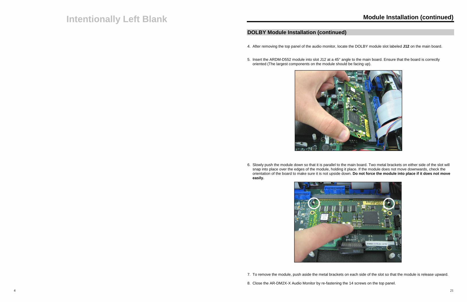
4. After removing the top panel of the audio monitor, locate the DOLBY module slot labeled J12 on the main board.
5. Insert the ARDM-D552 module into slot J12 at a 45° angle to the main board. Ensure that the board is correctlyoriented (The largest components on the module should be facing up).
6. Slowly push the module down so that it is parallel to the main board. Two metal brackets on either side of the slot willsnap into place over the edges of the module, holding it place. If the module does not move downwards, check theorientation of the board to make sure it is not upside down. Do not force the module into place if it does not moveeasily.
7. To remove the module, push aside the metal brackets on each side of the slot so that the module is release upward.
8. Close the AR-DM2X-X Audio Monitor by re-fastening the 14 screws on the top panel.
20
Module Installation (continued)
DOLBY Module Installation
IMPORTANT: The following procedure involves exposing and handling bare electronic components. Proper anti-staticprecaution must be taken before opening the AR-DM2X-X Audio Monitor to avoid damage during installation. Thisincludes working on a static-free surface and wearing a grounded wrist-strap or another type of grounding device.Opening the AR-DM2X-X Audio Monitor without proper anti-static precaution may void the warranty. For furtherinformation, contact Marshall Electronics.
Use the following instructions to install the ARDM-D552 module in the AR-DM2X-X Audio Monitor.
1. Ensure that power is disconnected from the audio monitor.
2. Disconnect all inputs and outputs.
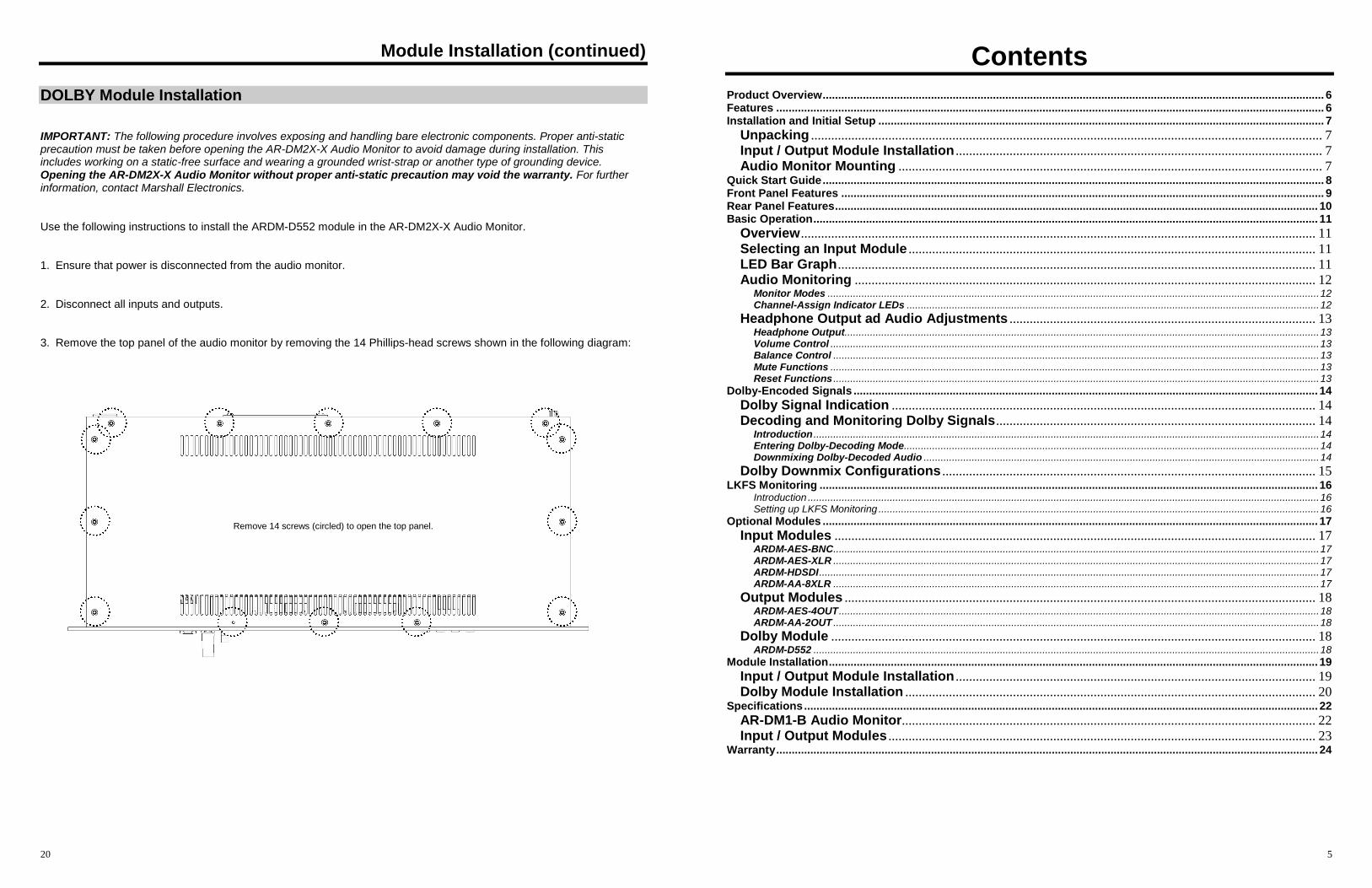
3. Remove the top panel of the audio monitor by removing the 14 Phillips-head screws shown in the following diagram:
Remove 14 screws (circled) to open the top panel.
5
ContentsProduct Overview.................................................................................................................................................................. 6Features ................................................................................................................................................................................. 6Installation and Initial Setup ................................................................................................................................................ 7
Unpacking ........................................................................................................................................................ 7Input / Output Module Installation ............................................................................................................. 7Audio Monitor Mounting .............................................................................................................................. 7
Quick Start Guide.................................................................................................................................................................. 8Front Panel Features ............................................................................................................................................................ 9Rear Panel Features............................................................................................................................................................ 10Basic Operation................................................................................................................................................................... 11
Overview......................................................................................................................................................... 11Selecting an Input Module ......................................................................................................................... 11LED Bar Graph.............................................................................................................................................. 11Audio Monitoring ......................................................................................................................................... 12
Monitor Modes ..............................................................................................................................................................................12Channel-Assign Indicator LEDs ..................................................................................................................................................12
Headphone Output ad Audio Adjustments ........................................................................................... 13Headphone Output........................................................................................................................................................................13Volume Control .............................................................................................................................................................................13Balance Control ............................................................................................................................................................................13Mute Functions .............................................................................................................................................................................13Reset Functions ............................................................................................................................................................................13
Dolby-Encoded Signals ...................................................................................................................................................... 14
Dolby Signal Indication .............................................................................................................................. 14Decoding and Monitoring Dolby Signals............................................................................................... 14
Introduction ...................................................................................................................................................................................14Entering Dolby-Decoding Mode...................................................................................................................................................14Downmixing Dolby-Decoded Audio ............................................................................................................................................14
Dolby Downmix Configurations ............................................................................................................... 15LKFS Monitoring ................................................................................................................................................................. 16
Introduction .....................................................................................................................................................................................16Setting up LKFS Monitoring ............................................................................................................................................................16
Optional Modules ................................................................................................................................................................ 17
Input Modules ............................................................................................................................................... 17ARDM-AES-BNC............................................................................................................................................................................17ARDM-AES-XLR ............................................................................................................................................................................17ARDM-HDSDI.................................................................................................................................................................................17ARDM-AA-8XLR ............................................................................................................................................................................17
Output Modules ............................................................................................................................................ 18ARDM-AES-4OUT..........................................................................................................................................................................18ARDM-AA-2OUT ............................................................................................................................................................................18
Dolby Module ................................................................................................................................................ 18ARDM-D552 ...................................................................................................................................................................................18
Module Installation.............................................................................................................................................................. 19
Input / Output Module Installation ........................................................................................................... 19Dolby Module Installation .......................................................................................................................... 20
Specifications...................................................................................................................................................................... 22
AR-DM1-B Audio Monitor........................................................................................................................... 22Input / Output Modules ............................................................................................................................... 23
Warranty............................................................................................................................................................................... 24
Product OverviewThe AR-DM2X-X series is a 16-channel digital audio monitoring system, featuring tri-color LED bar graphs on certainmodels. Designed for ultra-near field audio monitoring in space critical environments, the AR-DM2X-X series is ideal forTV facilities, studios, post-production facilities, VTR bays, mobile production vehicles, satellite links, and wherever multi-channel audio monitoring is required.
The AR-DM2X-X series features stereo loudspeakers in compact 1RU or 2RU form factors, with Class D Amplificationand 100% digital processing providing pristine audio quality. Interchangeable input and output modules provide unrivaledflexibility – up to four I/O modules can be installed in a single AR-DM2X-X audio monitor, each module with up to 16channel inputs, providing a possible 64 channels per audio monitor. Input choices include balanced/unbalancedAES/EBU, SDI video with embedded audio, and balanced analog audio. With an optional DOLBY
®module, the AR-
DM2X-X supports decoding and monitoring of DOLBY®
E and DOLBY®
DIGITAL (AC-3) signals, with the option to outputdiscrete decoded channels or pass through encoded bit streams. Flexible monitoring modes include mono, stereo, andvarious stereo downmix configurations for multi-channel audio. Additional features include volume and balance controls, aheadphone jack, and a USB port for on-site firmware upgrades.
Features■ Superior Audio Quality
Stereo Loud Speakers provide superior audio quality in a compact 1RU or 2RU form factor.
■ Flexible I/OModular design allows the AR-DM2X-X series monitors to be customized with a variety of inputs and outputs, includingbalanced and unbalanced AES/EBU, SDI with embedded audio, and balanced analog audio.
■ Selectable Stereo Downmix ConfigurationsMulti-channel audio can be downmixed in a variety of stereo configurations including 5.1, 7.1 and more.
■ LKFS Monitoring via LED Bar GraphThe AR-DM2X-X series of audio monitors allows a view of LKFS values for the audio input currently being monitored(1-B and 2-B only).
■ DOLBY DIGITAL / DOLBY E DecodingOptional ARDM-D552 module allows decoding of DOLBY E and DOLBY DIGITAL multi-channel audio signals.Decoded channels can be output via output modules. A variety of downmix presets based on DOLBY metadata areavailable, including Lt/Rt, Lo/Ro, etc.
® DOLBY is a registered trademark of Dolby Laboratories
Module Installation
Input / Output Module Installation
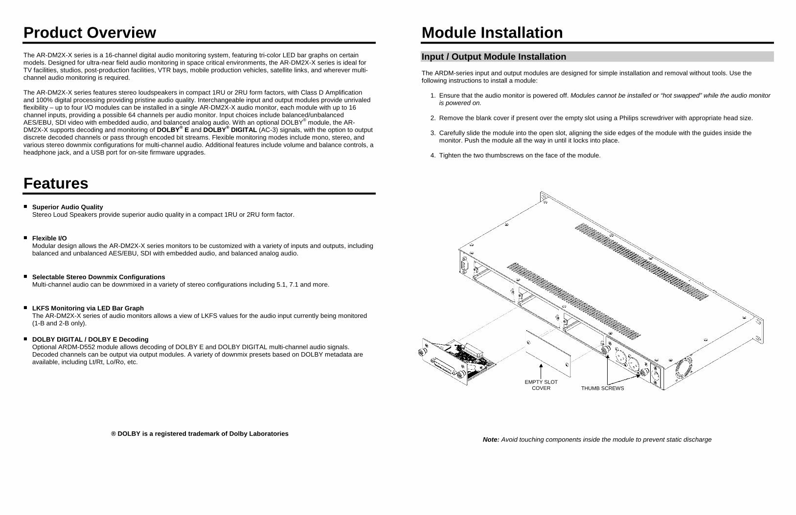
The ARDM-series input and output modules are designed for simple installation and removal without tools. Use thefollowing instructions to install a module:
1. Ensure that the audio monitor is powered off. Modules cannot be installed or “hot swapped” while the audio monitoris powered on.
2. Remove the blank cover if present over the empty slot using a Philips screwdriver with appropriate head size.
3. Carefully slide the module into the open slot, aligning the side edges of the module with the guides inside themonitor. Push the module all the way in until it locks into place.
4. Tighten the two thumbscrews on the face of the module.
Note: Avoid touching components inside the module to prevent static discharge
THUMB SCREWSEMPTY SLOT
COVER
18
Optional Modules (continued)
Output Modules
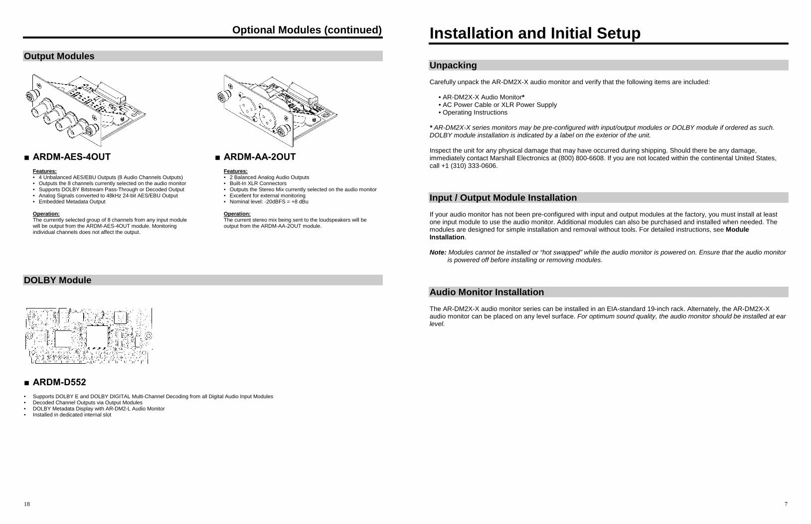
■ ARDM-AES-4OUT
Features:• 4 Unbalanced AES/EBU Outputs (8 Audio Channels Outputs)• Outputs the 8 channels currently selected on the audio monitor• Supports DOLBY Bitstream Pass-Through or Decoded Output• Analog Signals converted to 48kHz 24-bit AES/EBU Output• Embedded Metadata Output
Operation:The currently selected group of 8 channels from any input modulewill be output from the ARDM-AES-4OUT module. Monitoringindividual channels does not affect the output.
■ ARDM-AA-2OUT
Features:• 2 Balanced Analog Audio Outputs• Built-In XLR Connectors• Outputs the Stereo Mix currently selected on the audio monitor• Excellent for external monitoring• Nominal level: -20dBFS = +8 dBu
Operation:The current stereo mix being sent to the loudspeakers will beoutput from the ARDM-AA-2OUT module.
DOLBY Module
■ ARDM-D552
• Supports DOLBY E and DOLBY DIGITAL Multi-Channel Decoding from all Digital Audio Input Modules• Decoded Channel Outputs via Output Modules• DOLBY Metadata Display with AR-DM2-L Audio Monitor• Installed in dedicated internal slot
7
Installation and Initial Setup
Unpacking
Carefully unpack the AR-DM2X-X audio monitor and verify that the following items are included:
• AR-DM2X-X Audio Monitor*• AC Power Cable or XLR Power Supply• Operating Instructions
* AR-DM2X-X series monitors may be pre-configured with input/output modules or DOLBY module if ordered as such.DOLBY module installation is indicated by a label on the exterior of the unit.
Inspect the unit for any physical damage that may have occurred during shipping. Should there be any damage,immediately contact Marshall Electronics at (800) 800-6608. If you are not located within the continental United States,call +1 (310) 333-0606.
Input / Output Module Installation
If your audio monitor has not been pre-configured with input and output modules at the factory, you must install at leastone input module to use the audio monitor. Additional modules can also be purchased and installed when needed. Themodules are designed for simple installation and removal without tools. For detailed instructions, see ModuleInstallation.
Note: Modules cannot be installed or “hot swapped” while the audio monitor is powered on. Ensure that the audio monitoris powered off before installing or removing modules.
Audio Monitor Installation
The AR-DM2X-X audio monitor series can be installed in an EIA-standard 19-inch rack. Alternately, the AR-DM2X-Xaudio monitor can be placed on any level surface. For optimum sound quality, the audio monitor should be installed at earlevel.
8
Quick Start Guide
1. Install an Input ModuleEnsure at least one input module is installed in the AR-DM2X-X audio monitor. If no modules are installed, seeModule Installation for detailed instructions.
2. Connect an Audio SourceConnect an audio source to the audio monitor. Depending on the chosen input module, the signal could be SDIvideo with embedded audio, AES/EBU digital audio, analog audio, etc. Some modules may require a breakoutcable for the appropriate connections. See module specifications for details.
3. Power On the Audio MonitorSupply power to the audio monitor by connecting the included power supply to an AC power source (100-240 V @50/60 Hz) and connecting the power supply’s 4-pin XLR connector to the back of the audio monitor. The Power LEDon the front panel will illuminate green.
4. Select an Input ModuleUsing the SRC switch on the front panel, choose the module location (1-4) to which the input is connected (Modulesare identified as numbers 1-4, with location no.1 on the far left if facing the rear of the audio monitor). The LED bargraphs will then immediately show which channels have an audio signal present. You may not hear audio as yet.
5. Choose a Monitor ModeTo hear one audio channel at a time, press the Single button. To hear a stereo pair of channels, press the Pairbutton. Use the Left and Right buttons to switch channels or channel pairs. The LEDs under each bar graph willindicate which channels are selected. To hear channels 9-16, press the 9-16 button.
6. Adjust the Volume and BalanceUse the Volume and Balance controls to adjust the sound level and stereo balance.
17
Optional Modules
Input Modules
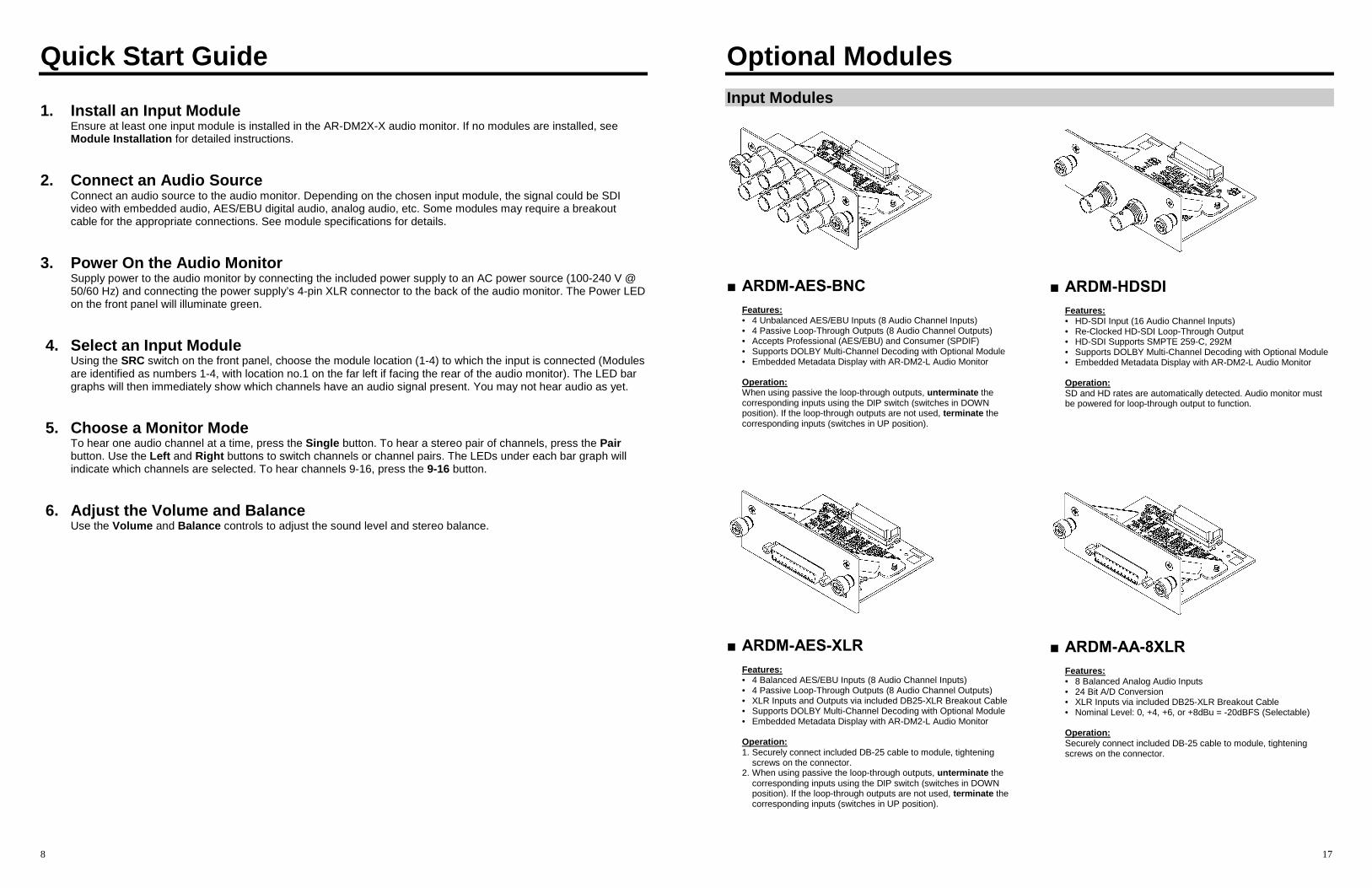
■ ARDM-AES-BNC
Features:• 4 Unbalanced AES/EBU Inputs (8 Audio Channel Inputs)• 4 Passive Loop-Through Outputs (8 Audio Channel Outputs)• Accepts Professional (AES/EBU) and Consumer (SPDIF)• Supports DOLBY Multi-Channel Decoding with Optional Module• Embedded Metadata Display with AR-DM2-L Audio Monitor
Operation:When using passive the loop-through outputs, unterminate thecorresponding inputs using the DIP switch (switches in DOWNposition). If the loop-through outputs are not used, terminate thecorresponding inputs (switches in UP position).
■ ARDM-AES-XLR
Features:• 4 Balanced AES/EBU Inputs (8 Audio Channel Inputs)• 4 Passive Loop-Through Outputs (8 Audio Channel Outputs)• XLR Inputs and Outputs via included DB25-XLR Breakout Cable• Supports DOLBY Multi-Channel Decoding with Optional Module• Embedded Metadata Display with AR-DM2-L Audio Monitor
Operation:1. Securely connect included DB-25 cable to module, tightening
screws on the connector.2. When using passive the loop-through outputs, unterminate the
corresponding inputs using the DIP switch (switches in DOWNposition). If the loop-through outputs are not used, terminate thecorresponding inputs (switches in UP position).
■ ARDM-HDSDI
Features:• HD-SDI Input (16 Audio Channel Inputs)• Re-Clocked HD-SDI Loop-Through Output• HD-SDI Supports SMPTE 259-C, 292M• Supports DOLBY Multi-Channel Decoding with Optional Module• Embedded Metadata Display with AR-DM2-L Audio Monitor
Operation:SD and HD rates are automatically detected. Audio monitor mustbe powered for loop-through output to function.
■ ARDM-AA-8XLR
Features:• 8 Balanced Analog Audio Inputs• 24 Bit A/D Conversion• XLR Inputs via included DB25-XLR Breakout Cable• Nominal Level: 0, +4, +6, or +8dBu = -20dBFS (Selectable)
Operation:Securely connect included DB-25 cable to module, tighteningscrews on the connector.
16
LKFS Monitoring
■ Introduction
Beginning in December 2012, the CALM Act requires TV stations, cable and satellite TV operators in the U.S. to limit acommercial’s average volume to that of the accompanying program. Marshall’s AR-DM2-X audio monitors allow themonitoring of LKFS values with automatic logging of LKFS values plus three different automatic indicators. The automaticindicators are designed to assist operators to quickly identify non-compliant signals in a real world working environment.Visual alarms, tone alarms and auto-email notification support operations even when operators and engineers arefocused on something else.
■ Setting up LKFS Monitoring (1-B and 2-B Configurations)
While monitoring an audio signal on the AR-DM2-X systems, pressing the [Single] and [Pair] buttons simultaneouslyenables the real time LKFS monitor on LED Bar Graphs 15-16, along with the blue LED above the DOLBY insignia toindicate that LKFS monitoring is enabled. Simultaneously pressing the [Single] and [Pair] button once more disablesLKFS monitor and returns LED Bar Graphs 15-16 to normal operation.
■ Logging LKFS Data (all AR-DM2X-X monitors) over USB
Using the provided configuration files, follow the
.ardmrc.xxx : This file is important, as it allows for the setting of the ARDM unit number in cases where multipleAR-DM2-X systems are deployed. It also allows for configuration of email recipients in case of LKFS valuesexceeding a set limit..calmConfig_IM: Enable or disable the LKFS value alert (exceeds a set value) and to set a value at which thealert is turned on. By default, the file configures the alert level at -24 LKFS..calmConfig_LogFile: Configure the log capabilities of the ARDM2X system. This file allows you to set themonitoring window for LKFS values. In addition, you can set the system to send all log data to an FTP server..calmConfig_MixPreset: Allows for configuration of up to 20 different presets with specific channel gains and forloudness calculations.
9
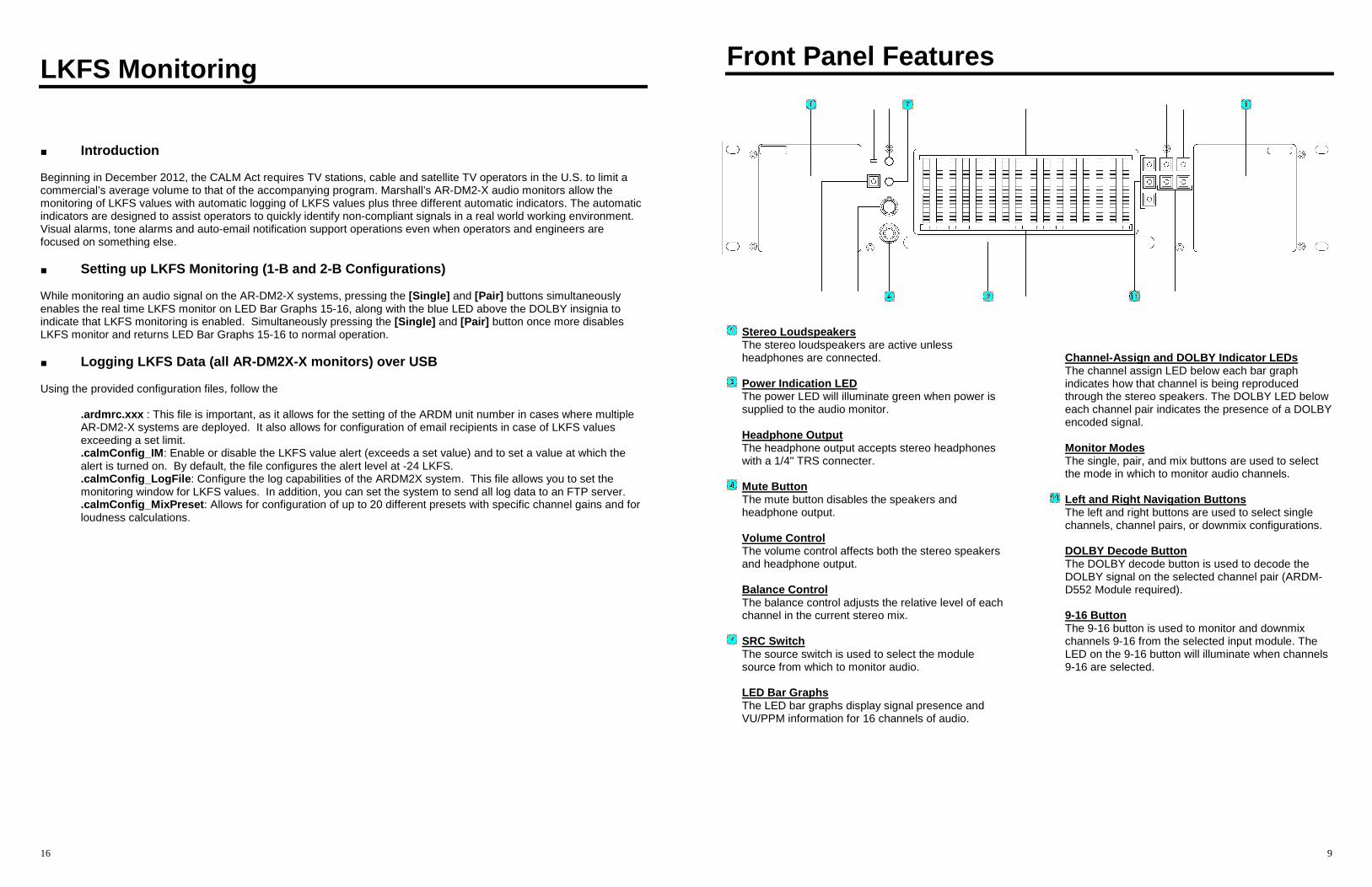
Front Panel Features
Stereo LoudspeakersThe stereo loudspeakers are active unlessheadphones are connected.
Power Indication LEDThe power LED will illuminate green when power issupplied to the audio monitor.
Headphone OutputThe headphone output accepts stereo headphoneswith a 1/4" TRS connecter.
Mute ButtonThe mute button disables the speakers andheadphone output.
Volume ControlThe volume control affects both the stereo speakersand headphone output.
Balance ControlThe balance control adjusts the relative level of eachchannel in the current stereo mix.
SRC SwitchThe source switch is used to select the modulesource from which to monitor audio.
LED Bar GraphsThe LED bar graphs display signal presence andVU/PPM information for 16 channels of audio.
Channel-Assign and DOLBY Indicator LEDsThe channel assign LED below each bar graphindicates how that channel is being reproducedthrough the stereo speakers. The DOLBY LED beloweach channel pair indicates the presence of a DOLBYencoded signal.
Monitor ModesThe single, pair, and mix buttons are used to selectthe mode in which to monitor audio channels.
Left and Right Navigation ButtonsThe left and right buttons are used to select singlechannels, channel pairs, or downmix configurations.
DOLBY Decode ButtonThe DOLBY decode button is used to decode theDOLBY signal on the selected channel pair (ARDM-D552 Module required).
9-16 ButtonThe 9-16 button is used to monitor and downmixchannels 9-16 from the selected input module. TheLED on the 9-16 button will illuminate when channels9-16 are selected.
10
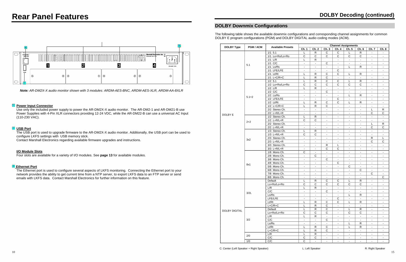
Rear Panel Features
Note: AR-DM2X-X audio monitor shown with 3 modules: ARDM-AES-BNC, ARDM-AES-XLR, ARDM-AA-8XLR
Power Input ConnectorUse only the included power supply to power the AR-DM2X-X audio monitor. The AR-DM2-1 and AR-DM21-B usePower Supplies with 4-Pin XLR connectors providing 12-24 VDC, while the AR-DM22-B can use a universal AC Input(110-230 VAC).
USB PortThe USB port is used to upgrade firmware to the AR-DM2X-X audio monitor. Additionally, the USB port can be used toconfigure LKFS settings with USB memory stick.Contact Marshall Electronics regarding available firmware upgrades and instructions.
I/O Module SlotsFour slots are available for a variety of I/O modules. See page 13 for available modules.
Ethernet PortThe Ethernet port is used to configure several aspects of LKFS monitoring. Connecting the Ethernet port to yournetwork provides the ability to get current time from a NTP server, to export LKFS data to an FTP server or sendemails with LKFS data. Contact Marshall Electronics for further information on this feature.
15
DOLBY Decoding (continued)
DOLBY Downmix Configurations
The following table shows the available downmix configurations and corresponding channel assignments for commonDOLBY E program configurations (PGM) and DOLBY DIGITAL audio coding modes (ACM).
Channel AssignmentsDOLBY Type PGM / ACM Available Presets
Ch. 1 Ch. 2 Ch. 3 Ch. 4 Ch. 5 Ch. 6 Ch. 7 Ch. 8
1/1 5.1 L R C C L R - -
1/1 Lo+Ro/Lo+Ro C C C C C C - -
1/1 L/R L R - - - - -
1/1 C/C - - C - - - - -
1/1 Ls/Rs - - - - L R - -
1/1 LFE/LFE - - - C - -
1/1 Lt/Rt L R C C L R - -
5.1
1/1 L+C/R+C L R C - - - - -
1/2 5.1 L R C C L R - -
1/2 Lo+Ro/Lo+Ro C C C C C C - -
1/2 L/R L R - - - - - -
1/2 C/C - - C - - - - -
1/2 Ls/Rs - - - - L R - -
1/2 LFE/LFE - - - C - - - -
1/2 Lt/Rt L R C C L R - -
1/2 L+C/R+C L R C - - - - -
2/2 Stereo Ch. - - - - - - L R
5.1+2
2/2 L+R/L+R - - - - - - C C
1/2 Stereo Ch. L R - - - - - -
1/2 L+R/L+R C C - - - - - -
2/2 Stereo Ch. - - - - - - L R2+2
2/2 L+R/L+R - - - - - - C C
1/3 Stereo Ch. L R - - - - - -
1/3 L+R/L+R C C - - - - - -
2/3 Stereo Ch. - - - - - - R L
2/3 L+R/L+R - - - - - - C C
3/3 Stereo Ch. - - R L - - - -
3x2
3/3 L+R/L+R - - C C - - - -
1/8 Mono Ch. C - - - - - - -
2/8 Mono Ch. - C - - - - - -
3/8 Mono Ch. - - C - - - - -
4/8 Mono Ch. - - - C - - - -
5/8 Mono Ch. - - - - C - - -
6/8 Mono Ch. - - - - - C - -
7/8 Mono Ch. - - - - - - C -
DOLBY E
8x1
8/8 Mono Ch. - - - - - - - C
Default L R C C L R - -
Lo+Ro/Lo+Ro C C C C C C - -
L/R L R - - - - - -
C/C - - C - - - - -
Ls/Rs - - - - L R - -
LFE/LFE - - - C - - - -
Lt/Rt L R C C L R - -
3/2L
L+C/R+C L R C - - - - -
Default L R C - L R - -
Lo+Ro/Lo+Ro C C C - C C - -
L/R L R - - - - - -
C/C - - C - - - - -
Ls/Rs - - - - L R - -
Lt/Rt L R C - L R - -
3/2
L+C/R+C L R C - - - - -
L/R L R - - - - - -2/0
C/C C C - - - - - -
DOLBY DIGITAL
1/0 C/C C - - - - - - -
C: Center (Left Speaker + Right Speaker) L: Left Speaker R: Right Speaker
14
DOLBY Encoded Signals
DOLBY Signal Indication
Illumination of the blue DOLBY LED underneath a channel pair indicates that a DOLBY encoded signal has beendetected on that channel pair.
What is a DOLBY Encoded Signal?A DOLBY encoded signal is a bitstream that contains multi-channel audio data compressed to fit in a single AES/EBUbitstream (one channel pair). A DOLBY bitstream can also be present in a pair of embedded audio channels in SDIvideo. Unlike with regular uncompressed digital audio (PCM), this bitstream must be decoded into its discrete channelsbefore it can be monitored as audio. Up to 8 discrete channels may be decoded from a DOLBY signal.
The ARDM-552 DOLBY Module must be installed in the AR-DM2X-X audio monitor in order to decode DOLBY signalsfrom any input module. If this module is not present, the AR-DM2X-X will indicate DOLBY signal presence with theaforementioned blue LED, but will not be able to decode the bitstream into discrete channels.
Decoding and Monitoring DOLBY Signals
■ Introduction
If your AR-DM2X-X has been configured with the optional ARDM-552 DOLBY Module, you will be able to decode andmonitor a DOLBY signal on any channel pair. Two varieties of DOLBY signals can be decoded: DOLBY DIGITAL (AC-3), and DOLBY E.
What is DOLBY DIGITAL?DOLBY DIGITAL, also known as AC-3, is an encoded bitstream that carries up to 6 discrete channels of audio.DOLBY DIGITAL is typically used to transmit a multi-channel audio program to consumers on a DVD or throughDTV.
What is DOLBY E?DOLBY E is an encoded bitstream that carries up to 8 discrete channels of audio. DOLBY E has several technicaladvantages over DOLBY DIGITAL, which make it ideal for distributing multi-channel audio within a productionenvironment using an existing AES/EBU pair of audio channels.
■ Entering DOLBY Decoding Mode
Once a DOLBY signal is detected, use the following steps to enter DOLBY decoding mode:
1. Press the PAIR button to enter the Pair monitor mode.2. Use the LEFT, RIGHT, and 9-16 buttons to select the channel pair containing the DOLBY bitstream.3. Press the DOLBY button to enter DOLBY decoding mode. Once this mode is entered, 8 channels of decoded
audio from the selected bitstream will appear on bar graphs 1-8 or 16-9, depending upon the source channelof the bitstream.
4. DOLBY decoding mode can be exited by pressing the DOLBY button again.5. Pressing the DOLBY button will have no effect without the ARDM-552 DOLBY Module installed, or if no
DOLBY bitstream is present.
■ Downmixing DOLBY Decoded Audio
As with non-encoded multi-channel audio, DOLBY decoded audio channels can be monitored in Single, Pair, orDownmix modes. In Downmix mode, however, several additional downmix configurations are available, depending onthe program format as described in the metadata of the DOLBY bitstream. See the DOLBY Downmix Configurationstable on page 12 for a table of available downmix configurations
11
Basic Operation
Overview
Basic operation of the AR-DM2X-X Audio Monitor involves selecting an input module as the audio source, using the LEDpresence indicators to monitor signal presence, or using the LED bar graphs to display signal levels, and choosing amode in which to monitor audio through the stereo speakers.
The user can switch between up to four installed I/O modules, each providing up to 16 channels of audio. The LEDpresence indicators will then display signal presence, or the LED bar graphs will display VU/PPM levels for each audiochannel from the selected input module. Finally, audio channels from the selected module can then be monitored throughthe stereo speakers in a variety of ways: Any single channel can be monitored in mono, any channel pair can bemonitored in stereo, and any group of eight channels can be down-mixed to stereo using a variety of configurations.
Selecting an Input Module
The SRC switch is used to select the source module from which to monitor audio.
• Module slots are identified with numbers 1-4, from left to right when facing the rear panel of the audio monitor.
• Only the selected module’s channel inputs can be monitored simultaneously. Audio channels from different inputmodules cannot be monitored at the same time. Loop-through outputs and dedicated output modules however willfunction at all times regardless of the selected module. See module specifications for details.
• If the SRC switch is set to a module slot where an output module or no module is present, no audio will be visible onthe meters or audible from the speakers.
• Each module location retains exclusive settings – Channel selections and mix configurations are saved separatelyfor each module (1-4) when switching modules. Settings are only reset once the module is removed from the audiomonitor. Volume, Balance, and Mute settings are common to all modules.
LED Bar Graphs
The LED signal presence indicators will display audio presence or the LED bar graphs will display signal levelinformation for each audio channel.
Once an input module is selected using the SRC switch, the LED signal presence indicators display signal presence orthe LED bar graphs immediately begin displaying signal level information for up to 16 channels of audio, depending on thenumber of channels available from the module. The bar graph for each channel will function even if that channel is notselected for monitoring through the stereo speakers as described in the Audio Monitoring section.
The LED bar graphs have the following functions:
Digital Audio Signal PresenceUnlike analog audio signals, digital audio signals contain a constant bit stream even when the audio content is silent.Such bit stream presence during silence is indicated by red illumination of the first LED segment of the correspondingchannel’s bar graph. This feature is useful in differentiating between an accidentally disconnected cable from silence inthe audio programming. This feature is not available for analog audio inputs.
VU/PPM Signal LevelEach LED bar graph (if available) represents the full scale of dynamic range of the audio monitor (-66dBFS to 0dBFS).Signal level is simultaneously displayed in two ways. Signal level is shown in Volume Units – the average volume ofthe signal – reflecting the perceive loudness of the signal. The bar graphs also function as Peak Program Meters,indicating signal peaks by displaying a single red bar at the peak level with a slow decay time.
12
Note: If a channel pair contains a DOLBY encoded signal, the corresponding LED bar graphs will not show a signal level.DOLBY signal presence is indicated by the illumination of the blue LED below each channel pair. See the DOLBYEncoded Signals section on page 13 for more information.
Basic Operation (continued)
Audio Monitoring
■ Monitor Modes
Audio channels from the selected input module can be monitored through the stereo speakers in three ways: onechannel at a time (mono), two channels at a time (stereo), or as a stereo mix of multiple channels (5.1, 7.1, etc.).
Single ModePress the SINGLE button to monitor one channel at a time. The selected channel will be reproduced through bothspeakers equally. Use the LEFT and RIGHT buttons to select amongst channels 1-8. Pressing the 9-16 buttonwill enable the LEFT and RIGHT buttons to select amongst channels 9-16.
Pair ModePress the PAIR button to monitor two channels as a stereo pair. The first channel of the pair will be reproducedthrough the left speaker, and the second through the right speaker. Use the LEFT and RIGHT buttons to selectamongst channel pairs 1/2, 3/4, 5/6, and 7/8. Pressing the 9-16 button will enable the LEFT and RIGHT buttons toselect amongst channel pairs 9/10, 11/12, 13/14, and 15/16.
Downmix ModePress the Mix button to monitor a stereo downmix of multiple audio channels. Press the 9-16 button to downmixchannels 9-16.
Three downmix configurations are available: 5.1, 7.1, and 4L+4R. The channel assignments in each downmixconfiguration are based on the DOLBY recommended track layout for Left, Right, Center, LFE (Low FrequencyEffect), Left Surround, and Right Surround channels. Press the LEFT and RIGHT buttons to select amongst theseconfigurations.
The following table shows how each audio channel is monitored through the speakers for each of the availabledownmix configurations:
Preset Ch. 1 Ch. 2 Ch. 3 Ch. 4 Ch. 5 Ch. 6 Ch. 7 Ch. 85.1 L R C C L R - -7.1 L R C C L R L R4L+4R L R L R L R L R
C: Center (Left Speaker + Right Speaker)L: Left SpeakerR: Right Speaker
■ Channel-Assign Indicator LEDs
In all monitor modes and downmix configurations, the Channel-Assign Indicator LED directly below each channel’ssignal presence indicator or bar graph indicates how that channel is currently being monitored through speakers.
The following table shows the LED color indicates channel assignment:
LED Color Channel Assigment
Orange Left Speaker + Right Speaker
Green Left Speaker
Red Right Speaker
(No Illumination) (Muted)
13
Basic Operation (continued)
Headphone Output and Audio Adjustments
■ Headphone Output
The headphone output accepts standard stereo headphones with a 1/4" TRS connector. Headphones with an 1/8”(3.5mm) mini-plug connector may be used with an adapter. The stereo speakers are muted when a connector isplugged into the headphone output.
■ Volume Control
The VOLUME control affects both the stereo speakers and the headphone output.
■ Balance Control
The BALANCE control adjusts the relative levels of the two channels of the current stereo mix, affecting both thestereo speakers and headphone output.
■ Mute Functions
The MUTE button affects both the stereo speakers and headphone output:
• Press the MUTE button once to mute both the speakers and headphone output. Press again to un-mute.
The LED on the MUTE button illuminates when either or both speakers are muted.
■ Reset Functions
The MUTE button can also be used to reset the audio monitor:
• Press and hold the MUTE button for 4 seconds to reset the audio monitor software.
• Power cycle the audio monitor while holding down the MUTE button to reset all presets and reset the monitor toits factory default configuration.


![AR North America Operating Instructions & Parts Manual AR ... · GPM Speed [RPM] 500 700 1000 1300 1500 2000 2500 3000 3500 4000 4500 5000 7250 ... AR North America Operating Instructions](https://img.pdfslide.us/doc/110x75/61482cb2cee6357ef9252ec6/ar-north-america-operating-instructions-parts-manual-ar-gpm-speed-rpm.jpg)