Embed Size (px)
Citation preview
Aquatecture. Macro-design Projectson the Theme "Water":Floating Fields
Edited by Charles L. Owen
Institute of DesignILLINOIS INSTITUTE OF TECHNOLOGY
Foun
ded
as th
e Ne
w Ba
uhau
s in
193
7, C
hica
go’s
Inst
itute
of D
esig
n, II
Tis
a c
ente
r fo
r ad
vanc
ed s
tudy
in h
uman
-cen
tere
d in
nova
tion.
Le
arn
mor
e: w
ww.id
.iit.e
du
Reissued: July, 2004

2 Charles L. Owen, ed. Aquatecture: Floating Fields
Published previously as a section of: Aquatecture: Four Macro-design Projects on the Theme: "Water". Charles L. Owen, ed. Chicago: Institute of Design, Illinois Institute ofTechnology. 1987.
Keywords: structured planning, systems design, concept development,macro-engineering, ocean technology, mariculture, aquaculture
Three additional Aquatecture project reports are available under the subtitles:CrossRoads in the SeaPatterned EnergyMobile Offshore Industry
Detailed information on the Structured Planning process used for this project canbe found in papers by Prof. Charles Owen on the Institute of Design web site:www.id.iit.edu
Inst
itute
of D
esig
n, Il
linoi
s In
stitu
te o
f Tec
hnol
ogy
Aqua
tectu
re. M
acro
-des
ign P
rojec
ts on
the
Them
e "W
ater
": Fl
oatin
g Fi
elds
/ Owe
n, C
harle
s L.
, ed.
/ Fi
rst p
rinte
d 19
87, R
eissu
ed 2
004
Charles L. Owen, ed. Aquatecture: Floating Fields 3
Preface
Mankind is inextricably bound to the water. Beyond our own obviousphysiological needs, there are its associations with other life forms of concern tous, its importance as a medium for transportation and commerce and, above all,its very omnipresence. Three quarters of the Earth’s surface is covered by water,and a great percentage of the world’s population lives close to large bodies ofwater.
The contrast between development of the resources of land and sea, however,is sharp. The disparity suggests that, as we near the new millennium, we considerthoughtfully how to extend to the seas the understanding we have gained indeveloping the land for human habitation and support of our societies. Activitiesthat were conceived for and evolved on land might now be better conducted onthe waters, given the maturation of our technological knowledge and thecrowding of our land base.
Aquatecture is a conceptual systems design project. Drawing on thecomputer-supported techniques of Structured Planning, it explores possibilities foruses of water resources for food production, transportation, energy developmentand manufacturing. Four subprojects: Floating Fields, CrossRoads in the Sea,Patterned Energy and Mobile Offshore Industry, deal individually with thesesubjects. In separate project reports, each speculates on how a "macrodesigned"environment might be developed using known technology to expand the uses ofthe seas, lakes and rivers as space, media and sources of energy, food and rawmaterials. This report describes Floating Fields.
All four projects were done in the Fall 1986 Systems and Systematic Designcourse at the Institute of Design. This course is the final course in a three-coursesequence for product design students beginning with Product Design, continuingwith Environmental Design, and ending with the Systems and Systematic Designcourse. The Systems course is concerned with products working in concert toachieve goals; the development of comprehensive design concepts; the problemsof teamwork in design; and the use of systematic, computer-supported designtechniques (Structured Planning) for handling complex problems.
The topic for the fall 1986 course was the Japan Design Foundation’s ThirdInternational Design Competition. Within the competition theme of "water", fourstudy areas were set out: food production, transportation, energy and materialsprocessing. Research in these areas evolved projects, collectively entitled"Aquatecture", which explore visions for uses of the oceans, lakes and rivers.
The projects were completed in four months and submitted to the competitionin January, 1987. From a field of 2,281 entries representing 58 countries, 1,144projects were actually submitted from professionals and students in 48 countries.All four of the Institute of Design projects survived the first round to be among59 finalists. After another month of work to prepare final presentations, a secondsubmission was made in June. Final competition results were announced inAugust: the four Aquatecture projects were together awarded the Grand Prize of10,000,000 yen ($78,500). The award, made in Osaka on October 30, 1987,marked the second time in three competitions that Institute of Design studentshad won the Grand Prize.
The projects received considerable attention in the world press. Perhaps thebest presentation of them was in the Italian international magazine ofarchitecture: L’ARCA. Its April 1988 issue (No. 15) contains a ten page articlewith a number of drawings and color photographs.
Charles L. Owen, Advisor and Editor
Inst
itute
of D
esig
n, Il
linoi
s In
stitu
te o
f Tec
hnol
ogy
http
://ww
w.id.
iit.ed
u
Reiss
ued
July,
200
4

4 Charles L. Owen, ed. Aquatecture: Floating Fields
Inst
itute
of D
esig
n, Il
linoi
s In
stitu
te o
f Tec
hnol
ogy
http
://ww
w.id.
iit.ed
u
Charles L. Owen, ed. Aquatecture: Floating Fields 5
Design/Planning Team Maura Podrazik
Team Leader Mark Elliott Erik Newman Mark Shaw Steven Tornallyay
Floating Fields
OverviewThe water environments of the world provide ideal locations forthe production of food. Aquaculture and mariculture successesalready prove the potential for farming the seas, lakes and rivers.What remains is to design structural systems capable ofincorporating the variety of processes possible into integratedproduction facilities tailored to the water environment, its nutritivequalities and the crop requirements of the farmers.
"Floating Fields" establishes farming in a new frontier. Landfarming (in the form of hydroponics) as well as water farming ismoved from increasingly crowded and valuable land locations tonew sites on the water. Within an "Aquatecture" structure, afloating Distribution Spine anchored to the bottom connects anumber of kinds of production facilities. The Distribution Spineorganizes the system and provides a path for moving materials,seedlings and harvests between fields and processing facilities.Functional components are modular and designed to beincorporated in arrangements virtually unlimited by size orcomplexity—the sample organization shown is approximately onekilometer in length. Combined with other Aquatectural structuresfor wave protection, energy generation, desalination andprocessing of the harvest, Floating Fields can occupy a variety ofenvironments.
Systems ElementsThe elements of the Floating Fields system can be organized intotwo categories: Production Elements and Service Elements. TheProduction Elements are the elements which are directly linked tothe growing of plants or the raising of stock. Service Elements areelements that support and sustain the production elements.
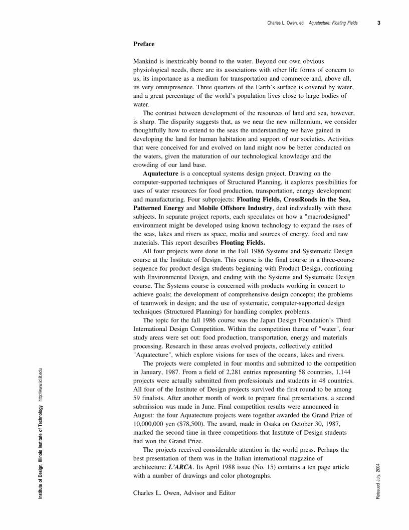
Figure 1 Floating FieldsA system of floating food production units connected with elements of a distribution spine creates ahighly flexible mariculture and hydroponic system adaptable to a wide range of needs and conditions.
Inst
itute
of D
esig
n, Il
linoi
s In
stitu
te o
f Tec
hnol
ogy
http
://ww
w.id.
iit.ed
u
Reiss
ued
July,
200
4
6 Charles L. Owen, ed. Aquatecture: Floating Fields
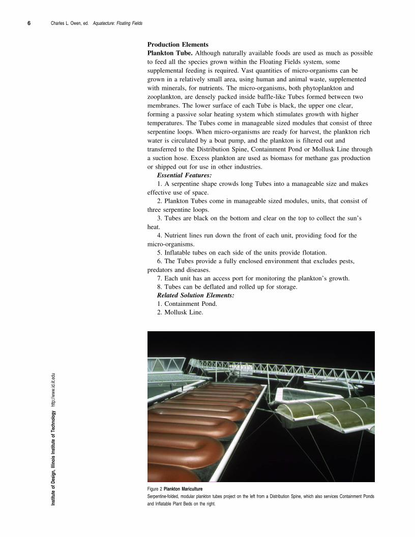
Production ElementsPlankton Tube. Although naturally available foods are used as much as possibleto feed all the species grown within the Floating Fields system, somesupplemental feeding is required. Vast quantities of micro-organisms can begrown in a relatively small area, using human and animal waste, supplementedwith minerals, for nutrients. The micro-organisms, both phytoplankton andzooplankton, are densely packed inside baffle-like Tubes formed between twomembranes. The lower surface of each Tube is black, the upper one clear,forming a passive solar heating system which stimulates growth with highertemperatures. The Tubes come in manageable sized modules that consist of threeserpentine loops. When micro-organisms are ready for harvest, the plankton richwater is circulated by a boat pump, and the plankton is filtered out andtransferred to the Distribution Spine, Containment Pond or Mollusk Line througha suction hose. Excess plankton are used as biomass for methane gas productionor shipped out for use in other industries.
Essential Features: 1. A serpentine shape crowds long Tubes into a manageable size and makes
effective use of space.2. Plankton Tubes come in manageable sized modules, units, that consist of
three serpentine loops.3. Tubes are black on the bottom and clear on the top to collect the sun’s
heat.4. Nutrient lines run down the front of each unit, providing food for the
micro-organisms.5. Inflatable tubes on each side of the units provide flotation.6. The Tubes provide a fully enclosed environment that excludes pests,
predators and diseases.7. Each unit has an access port for monitoring the plankton’s growth.8. Tubes can be deflated and rolled up for storage.Related Solution Elements: 1. Containment Pond.2. Mollusk Line.
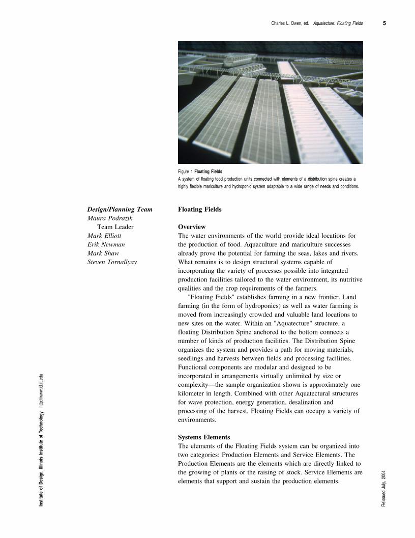
Figure 2 Plankton Mariculture Serpentine-folded, modular plankton tubes project on the left from a Distribution Spine, which also services Containment Pondsand Inflatable Plant Beds on the right.In
stitu
te o
f Des
ign,
Illin
ois
Inst
itute
of T
echn
olog
y ht
tp://
www.
id.iit.
edu
Charles L. Owen, ed. Aquatecture: Floating Fields 7
Kelp Stringer. Kelp is currently an established maricultural crop, providing animportant food for humans and aquatic or land animals. The cultivation processis well developed and straightforward; it has simply been modified to fit into theFloating Fields system.
Essential Features: 1. The Stringer is a weighted cable supported at either end by sections of
Float Walk.2. The Stringer provides an anchoring point for large kelp plants.3. Harvesting consists of cutting the top few meters of the kelp leaving the
rest anchored to the Stringer so it can continue to grow.Related Solution Elements: 1. Float Walk.
Aquatic Plant Screen. The cultivation of sea weed is an old and well developedform of mariculture, producing a valuable source of food for humans and aquaticor land animals. Where it can be economically marketed, seaweed may be amajor cash crop for a Floating Field installation. In other cases, it is important asan environmental or food factor for growing fish or other aquatic animals. Excesssea weed may be used as biomass for methane gas production, or harvested forspecialized uses in other industries.
Essential Features: 1. An Aquatic Plant Screen is a loose grid of ropes, supported on floats, that
provides anchoring points for aquatic plants.2. Aquatic Plant Screens are located in Containment Ponds.3. Floating Screens provide a source of food and a more natural environment
for some species of fish within the Containment Ponds.Related Solution Elements: 1. Containment Pond.
Hydroponic Quilt. One of the advantages of moving from the land out onto theocean surface is the vast amount of space available. The Hydroponic Quilt isintended to take advantage of that space for plants traditionally grown on land.Its component parts provide the shelter, support matrix and growing medium forraising plants without soil. Desalinated water, refortified with minerals selectivelyprocessed from sea water or, where necessary, imported from land-based sources,supplies nutrients in proportions that can be controlled for maximum yield in theshortest growing cycle.
Essential Features: 1. Hydroponic Quilts have three parts: an Inflatable Plant Bed, a Growing
Medium Mat, and an Inflatable Cover.2. Quilts form an enclosed environment suitable for Hydroponic cultivation.3. Quilts can be deflated and rolled up for storage when not in use.Related Solution Elements: 1. Controlled Environment.2. Inflatable Plant Bed.3. Growing Medium Mat.4. Inflatable Cover.
Inflatable Plant Bed. The Inflatable Plant Bed is one of three parts that make upthe Hydroponic Quilt. The Bed serves a dual purpose: first it provides theflotation to keep the other parts of the Hydroponic Quilt out of the water; andsecond, it acts as a barrier to prevent sea water from contaminating the growingenvironment.
Inst
itute
of D
esig
n, Il
linoi
s In
stitu
te o
f Tec
hnol
ogy
http
://ww
w.id.
iit.ed
u
Reiss
ued
July,
200
4
8 Charles L. Owen, ed. Aquatecture: Floating Fields
Essential Features: 1. Inflatable Plant Beds measure 24 m. by 1.5 m. by .5m.2. Material for Beds is plastic, deflatable for storage.3. Inflatable Plant Beds support the Growing Medium Mats and form a
continuous barrier between plants and the sea water.Related Solution Elements: 1. Hydroponic Quilt.2. Growing Medium Mat.3. Inflatable Cover.
Growing Medium Mat. New techniques must be employed to grow land plantson the water’s surface. The Growing Medium Mats are an essential component ofthe new methods. The Mats contain inert growing medium, which supports theplants while they are growing, and nutrient lines to distribute food to the plants.
The Mats are separate from the Inflatable Plant Beds so that they can beremoved from the Beds for harvesting, cleaning and reseeding. Cleaning andreseeding take place in the Processing Hub.
Essential Features: 1. Growing Medium Mats measure 23 m. by 1.4 m. by 3 m.2. Mats are baffle-shaped plastic tubes containing a growing matrix to support
plant roots.3. Built-in nutrient lines in the Mat’s plastic tubes feed the growing plants.4. After harvesting, Mats are cleaned, reseeded and reused.Related Solution Elements: 1. Hydroponic Quilt.2. Inflatable Plant Bed.3. Inflatable Cover.
Inflatable Cover. Hydroponic cultivation works best in an enclosed, controlledenvironment. The ocean environment, with its salt water and salt spray isdetrimental to most plants normally grown on land. Hydroponic Quilts,accordingly, need to be completely sealed from the outside environment. TheInflatable Covers, in conjunction with Inflatable Plant Beds, form an envelopethat not only protects plants from salt and sea, but also provides a barrier againstairborne seeds, pests and the diseases they might carry.
Essential Features: 1. Inflatable Covers measure 24 m. by 6 m. by 2 m.2. Covers protect hydroponically-raised plants from the sea environment.3. Support pontoons run the full length of a Cover along both sides.4. Cover connections to Inflatable Plant Beds form a sealed, completely
enclosed environment for Hydroponic cultivation.5. Positioning of Hydroponic Quilts is maintained by Cover connections to
the Distribution Spine.Related Solution Elements: 1. Hydroponic Quilt.2. Inflatable Plant Bed.3. Growing Medium Mat.
Controlled Environment. Almost all plant and animal species require specialenvironmental conditions at some point in their life cycles. This usually occurs inthe early stages of their development. The Controlled Environment is whereorganisms are provided with the special environmental conditions necessary atthese critical stages. Typical operations that take place in these greenhouse-likestructures are: the breeding and spawning of stock, hydroponic production ofIn
stitu
te o
f Des
ign,
Illin
ois
Inst
itute
of T
echn
olog
y ht
tp://
www.
id.iit.
edu
Charles L. Owen, ed. Aquatecture: Floating Fields 9
plant seedlings, implantation of plant seeds and shellfish spat on structuralsubstrates, and experimentation with new strains of crops.
Essential Features: 1. A Controlled Environment provides an enclosure within which temperature,
light, water salinity and all other environmental factors can be regulated.2. Controlled Environments are primarily used for starting hydroponic and
aquatic plantings and propagating fish and other animal stock.3. Experimental cultivation of species (plant or animal) where special
attention or environmental conditions are needed is conducted in a ControlledEnvironment.
4. Controlled Environments are constructed from standard Structural Modules,using panels to separate the internal environment from the external environment.
5. The structure has two levels, an upper level that is dry for growing plants,and a lower level flooded for aquatic species.
6. Flotation is provided by pontoons located around the perimeter and on thebottom of the structure.
Related Solution Elements: 1. Structural Module.
Mollusk Line. Mollusks are the oldest and still one of the most important ofmaricultural crops. The techniques for cultivating mollusks are well developed,but can be modified to improve processes of harvesting and seeding. Currently,mollusks are grown on strings hanging from rafts. To harvest the matureshellfish, a worker must travel from raft to raft raising individual strings, one byone. Harvesting efficiency is increased in the Floating Fields by using a systemof floating Mollusk Lines that circulate to bring the mature mollusks to theworker. As the nets with the mature mollusks are removed, newly seeded nets areinstalled on the line, thus accomplishing both harvesting and planting in oneoperation.
Essential Features: 1. Mollusks are grown on nets that hook onto a buoyed cable.2. Each Mollusk Line contains a continuous cable handling system that allows
nets to be moved, harvested and seeded from one location.3. Mollusk Lines are supported between Float Walks.Related Solution Elements: 1. Float Walk.
Containment Pond.Containing fish and other animals under cultivation in optimal-size environmentsis important for bringing stock to maximal size in the shortest time. ContainmentPonds come in several sizes and are stocked at optimal densities to minimize theamount of work (movement) necessary for animals to keep healthy, whileensuring that they have enough food to support maximal growth rates. Densitiesreflect the tradeoff between the amount of naturally available food and the costof supplemental feeds.
Essential Features: 1. Containment Ponds use a selectively permeable "Semi-Permeable
Membrane" to keep cultivated species in and unwanted wild species out, whileallowing nutrient rich waters to flow through.
2. A Pond’s bottom surface is raised by Air-Actuated Lifters to harvest fishor other animals.
3. Ponds are triangular in form so that fish will be concentrated in one of thevertices when the bottom is raised for harvesting.
Inst
itute
of D
esig
n, Il
linoi
s In
stitu
te o
f Tec
hnol
ogy
http
://ww
w.id.
iit.ed
u
Reiss
ued
July,
200
4
10 Charles L. Owen, ed. Aquatecture: Floating Fields
4. Ponds are anchored to the Distribution Spine to maintain their position.5. Buoyant Float Walks support the Containment Ponds and serve as
walkways for workers to use during harvesting, inspection, repair andmaintenance operations.
Related Solution Elements: 1. Distribution Spine.2. Semi-Permeable Membrane.3. Air-Actuated Lifter.4. Float Walk.
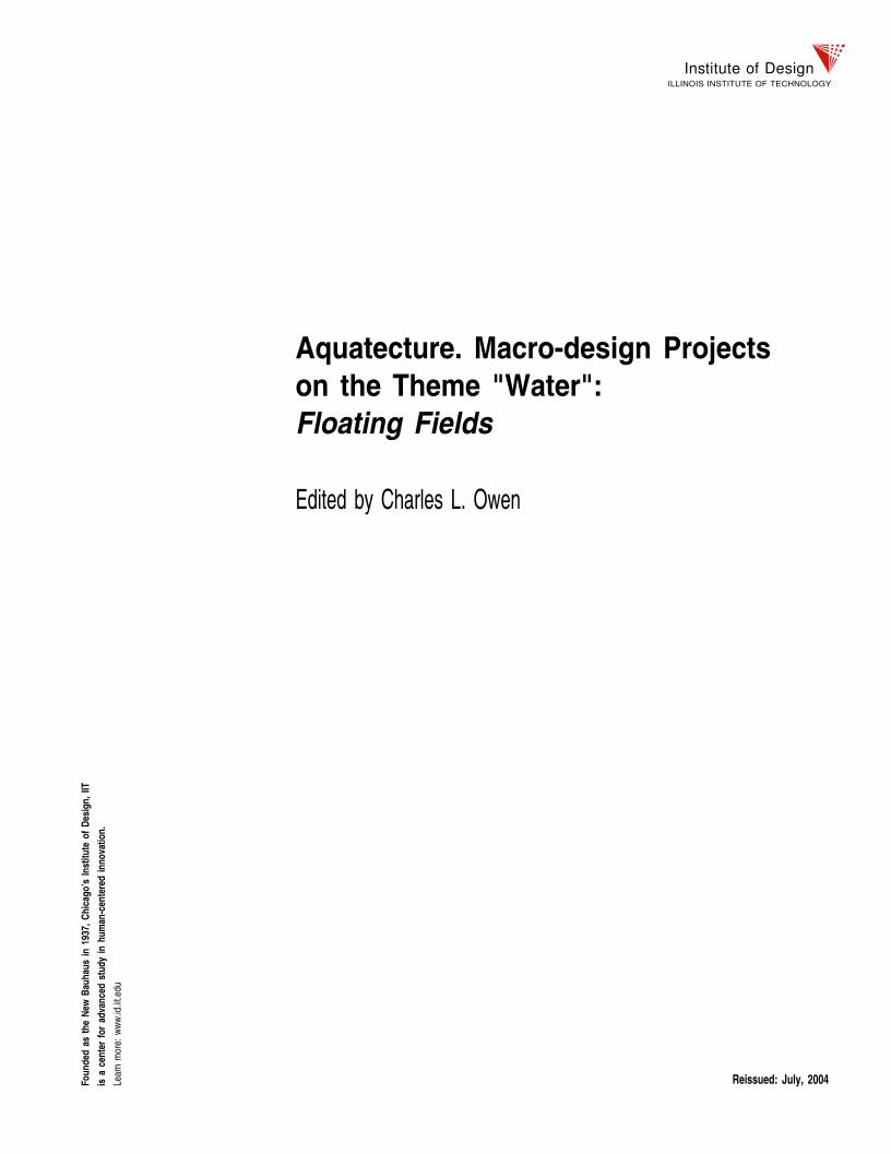
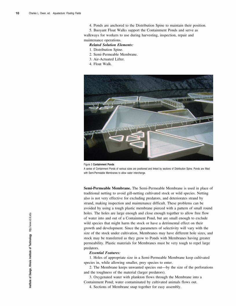
Figure 3 Containment Ponds A series of Containment Ponds of various sizes are positioned and linked by sections of Distribution Spine. Ponds are fittedwith Semi-Permeable Membranes to allow water interchange.
Semi-Permeable Membrane. The Semi-Permeable Membrane is used in place oftraditional netting to avoid gill-netting cultivated stock or wild species. Nettingalso is not very effective for excluding predators, and deteriorates strand bystrand, making inspection and maintenance difficult. These problems can beavoided by using a tough plastic membrane pierced with a pattern of small roundholes. The holes are large enough and close enough together to allow free flowof water into and out of a Containment Pond, but are small enough to excludewild species that might harm the stock or have a detrimental effect on theirgrowth and development. Since the parameters of selectivity will vary with thesize of the stock under cultivation, Membranes may have different hole sizes, andstock may be transferred as they grow to Ponds with Membranes having greaterpermeability. Plastic materials for Membranes must be very tough to repel largepredators.
Essential Features: 1. Holes of appropriate size in a Semi-Permeable Membrane keep cultivated
species in, while allowing smaller, prey species to enter.2. The Membrane keeps unwanted species out—by the size of the perforations
and the toughness of the material (larger predators).3. Oxygenated water with plankton flows through the Membrane into a
Containment Pond; water contaminated by cultivated animals flows out.4. Sections of Membrane snap together for easy assembly.In
stitu
te o
f Des
ign,
Illin
ois
Inst
itute
of T
echn
olog
y ht
tp://
www.
id.iit.
edu
Charles L. Owen, ed. Aquatecture: Floating Fields 11
5. Membranes, as components of Containment Ponds, are supported bybuoyant Float Walks.
Related Solution Elements: 1. Containment Pond.2. Float Walk.
Air-Actuated Lifter. For efficient harvesting, it is necessary to concentrate stockinto a confined area. Land-based fish farms simply drain their ponds until thefish are concentrated in a deep section of the pond built especially for harvesting.Raising the bottom of a floating Containment Pond does essentially the samething as draining a land-based pond; it decreases the distance between the watersurface and the Pond bottom and reduces the volume of water contained withinthe Pond. Using air, the bottom of the Pond is raised —without recourse tomachinery—by simply inflating a system of tubes molded into theSemi-Permeable Membrane. The tubes are called Air-Actuated Lifters.
By starting at one side of the Pond and raising a section at a time, fish orother animals can be forced into a continually reduced area until they areconcentrated enough for harvesting. After harvesting the Membrane can beinspected and repaired before the air is released from the Lifters and it is allowedto sink back to its original position.
Essential Features: 1. Air-Actuated Lifters are tubes which can be filled with air to raise a
Containment Pond’s bottom for harvesting.2. Lifter tubes are molded into the Semi-Permeable Membrane.3. Lifters can be actuated in sequence to herd fish or other animals into a
corner of the triangular Containment Ponds.4. Using air pressure for harvesting eliminates the need for winches or other
heavy machinery.Related Solution Elements:1. Containment Pond.2. Semi-Permeable Membrane.
Float Walk. There is a need for a common flotation element to providebuoyancy for other system elements. The use of a large rectangular float has anadvantage over traditionally shaped floats because it provides a surface uponwhich personnel can walk while performing the various tasks required about thefacility.
Essential Features: 1. Float Walks provide buoyant support for Semi-Permeable Membranes,
Kelp Stringers and Mollusk Lines.2. Float Walks create a work surface around each Containment Pond for
inspection, harvesting and repair operations.3. Construction is of light-weight plastic foam encased in a hard plastic shell.4. The rigidity of the Float Walk elements helps to define the shapes of
Containment Ponds.5. Top surfaces have a non-skid texture for good footing in wet conditions.6. Float Walks come in sections 3 m. by 1.5 m. by .5 m for easy handling.7. Sections are joined to the Semi-Permeable Membrane and to each other
with snap connectors for easy assembly.8. Specially shaped Float Walks are used to form the vertices of the
Containment Ponds.9. A special "Gate" module composed of flexible barriers allows the Work
Boats to pass freely while still retaining the stock.
Inst
itute
of D
esig
n, Il
linoi
s In
stitu
te o
f Tec
hnol
ogy
http
://ww
w.id.
iit.ed
u
Reiss
ued
July,
200
4
12 Charles L. Owen, ed. Aquatecture: Floating Fields
Related Solution Elements: 1. Containment Pond.2. Semi-Permeable Membrane.3. Mollusk Line.4. Kelp Stringer.
Service Elements
Structural Module. All structures within the Floating Fields system are builtfrom the same structural components. A module of 3 meters is a comfortabledimension for human scale, and it can be expanded without loss of modularity to6 and 12 meter lengths for larger structures. By using the same StructuralModule throughout the facility it is easy to link elements together at any point inthe system and add new elements where and whenever necessary.
Essential Features: 1. The Structural Module sets the dimensions and is the building-block
element for the infrastructure of the Floating Fields facility.2. In shape, the Structural Module is triangular in vertical section and square
in plan. Each side of the module is 3 meters long.3. Structural Modules are supported by submerged SWATH (Small
Water-plane Area Twin Hulls) pontoons. This form greatly reduces the motioneffects of wave action.
4. The ratio of flotation (air) to ballast (water) can be adjusted within thepontoons so that the correct amount of support is provided for each structuralelement.
5. Structures are held in position by anchor cables attached to the submergedSWATH pontoons and anchored to the sea floor.
6. Panels can be fixed to the structural framing to create environmentallyprotected enclosed areas.
Related Solution Elements: 1. Processing Hub.2. Distribution Spine.3. Worker’s Dwelling.4. Controlled Environment.
Work Boat. Because a Floating Fields installation can be very large, it isnecessary to have a specialized transportation system able to move personnel andequipment to locations of work activity. A Work Boat is the aquatic equivalentof a combined tractor and pick-up truck. The basic Boat is simply a shell whichcan be used as an unpowered barge for bulk items; a standard pump is mountedinside the Boat to provide power and propulsion. Boats can be modified toperform different tasks by the addition of interchangeable inserts. Since themachinery of the Floating Fields system is powered by air or water pressure, theWork Boats not only provide the means of transportation to a job site, they alsosupply the power to run equipment once the workers arrive. Not only does thisreduce requirements for machinery, it makes maintenance and repair by allowingwork on all power sources to take take place at take place at a specializedlocation—the Work Boat service center.
Essential Features: 1. Work Boats are molded of flotation foam encased in a hard plastic shell.
Boats are unsinkable, even when swamped.2. Work Boats are the primary means of transportation for Floating Fields
personnel.
Inst
itute
of D
esig
n, Il
linoi
s In
stitu
te o
f Tec
hnol
ogy
http
://ww
w.id.
iit.ed
u
Charles L. Owen, ed. Aquatecture: Floating Fields 13
3. Boats are operated by removable engine-driven pumps that pump water andcompress air. Water pump propulsion moves the Work Boats over seaweed bedswithout damage to plants, and provides a means of generating flows of water formaintenance operations with minimal danger to working personnel or animalstock.
4. Compressed air from the Boats’ pumps runs auxiliary equipment such asharvesters, Air-Actuated Lifters, hand tools, etc.
5. Work Boats are used for all construction and rearrangement jobs requiringthe towing or movement of structural components.
6. Boats are powered by methane gas produced in the Floating Fields system.7. The pump can be removed for easier maintenance, and the boat (with the
additional space) can be used as a barge to transport bulk items.8. Interchangeable inserts, powered by the standard pump, are used to modify
the function of the Boats for the different harvesting and planting jobs about thesystem.
Related Solution Elements: 1. Air-Actuated Lifter.2. Mollusk Line.3. Kelp Stringer.4. Hydroponic Quilt.
Distribution Spine. The Distribution Spine is the main artery through whichmaterial of almost all kinds is transported from one part of the Floating Fieldsfacility to another. Bulk materials are moved primarily through the Spine’sTransport Troughs; pipes in parallel move liquids and gases. During construction,modules of the Spine are anchored to the sea floor, turning the Spine into acentral "pier" to which other components can be connected. The SWATH hullpontoons which support the Spine are submerged deep enough below the watersurface and the Spine itself is raised high enough above the water that there is nointerference with Work Boat surface traffic.
Essential Features: 1. The Distribution Spine contains the means for conveying materials from
one part of the Floating Fields facility to another.2. The Spine is constructed from standard Structural Modules assembled into
sections 24 meters long.3. Spine sections are connected by ball-and-socket pivot joints to permit
motions in harmony with wave action.4. A walkway along the Spine acts as an auxiliary path for personnel and an
access platform for maintenance.5. The height of the Distribution Spine over the water is great enough to
allow Work Boats and their tows to pass underneath without interference.6. Because it is anchored to the sea floor throughout its length, the Spine acts
as a stable, central structure for positioning other elements of the system.7. Pipes within the Spine distribute gases and liquids throughout the facility.
Pipe joints every 24 meters contain a flexible connector to prevent rupture duringstorms.
8. Transport Troughs within the Spine are the primary means for distributingbulk materials.
Related Solution Elements: 1. Processing Hub.2. Structural Module.3. Transport Trough.
Inst
itute
of D
esig
n, Il
linoi
s In
stitu
te o
f Tec
hnol
ogy
http
://ww
w.id.
iit.ed
u
Reiss
ued
July,
200
4
14 Charles L. Owen, ed. Aquatecture: Floating Fields
Transport Trough. Water or air is used to power most system elements becauseof the dangers and maintenance problems associated with electro-mechanicalequipment in an ocean environment. The Transport Troughs are a good exampleof this. Troughs supply a shallow volume of fast moving water within aslick-surfaced container that moves items much like logs in a chute.
Most bulk materials that must be moved are already wet (harvested fish,seaweed, mollusks, etc.) or are soon to be wet (feeds, fertilizers, processedwastes). They can either be moved directly or can be containerized in smallpackages weighing less than 50 kilograms and readily supported by a smallamount of water. Small items that are desirably kept together are placed onspecial saucers whose bottom matches the interior contours of the Trough;materials which must be kept dry are loaded into water-tight reusable plastic bagsbefore being put into the Trough.
All the harvesting methods used in the Floating Fields system are directlylinked to use of the Transport Troughs. Some harvesting methods require atemporary link between remote field locations and the Distribution Spine. This isaccomplished by floating a string of Trough sections out into the field. As soonas a plant or animal crop is harvested, it is transported by the Trough to theProcessing Hub.
Essential Features: 1. The Transport Trough is constructed of light-weight foam covered by a
tough plastic shell.2. Within the shell, embedded in the foam, are small, high pressure water
pipes. Directional jets from the water pipes cover the interior of the Trough witha moving layer of water that provides support and locomotion for bulk materials.
3. Trough sections are 3 meters long and have quick disconnect fasteners forjoining water pipes.
4. Materials that must be kept dry are transported in reusable plastic bags.5. Materials to be kept together are transported on "saucers" which fit into the
contour of the Trough.6. Troughs are buoyant and can act as temporary links between the Fields and
the Distribution Spine.Related Solution Elements: 1. Distribution Spine.
Processing Hub. The Processing Hub is the heart of the Floating Fields system.Made from standard Structural Modules, it can be expanded or diminished inarea according to the needs of the individual facility. It provides the extensivework surface area necessary for processing crops or preparing materials fordistribution throughout the system. It also serves as the junction point linking thefacility to outside transportation. Sections of the Processing Hub are enclosed bypanels to provide protection from the elements for workers and goods.
Essential Features: 1. The Processing Hub is a sheltered work area where crops are processed for
market and supplies are prepared for use in the system.2. The Hub is the central point for the propagation of new Distribution
Spines.3. The Hub provides the physical link between the outside world and the
Floating Fields facility through its boat dock and helicopter pad.Related Solution Elements: 1. Structural Module.2. Distribution Spine.3. Worker Dwelling.4. Controlled Environment.In
stitu
te o
f Des
ign,
Illin
ois
Inst
itute
of T
echn
olog
y ht
tp://
www.
id.iit.
edu
Charles L. Owen, ed. Aquatecture: Floating Fields 15
5. Transpac.6. Transpac Storage Grid.
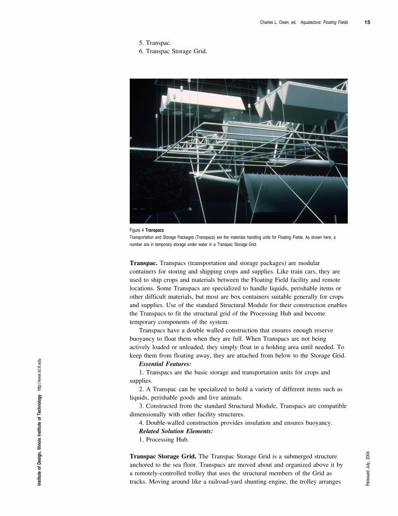
Figure 4 Transpacs Transportation and Storage Packages (Transpacs) are the materials handling units for Floating Fields. As shown here, anumber are in temporary storage under water in a Transpac Storage Grid.
Transpac. Transpacs (transportation and storage packages) are modularcontainers for storing and shipping crops and supplies. Like train cars, they areused to ship crops and materials between the Floating Field facility and remotelocations. Some Transpacs are specialized to handle liquids, perishable items orother difficult materials, but most are box containers suitable generally for cropsand supplies. Use of the standard Structural Module for their construction enablesthe Transpacs to fit the structural grid of the Processing Hub and becometemporary components of the system.
Transpacs have a double walled construction that ensures enough reservebuoyancy to float them when they are full. When Transpacs are not beingactively loaded or unloaded, they simply float in a holding area until needed. Tokeep them from floating away, they are attached from below to the Storage Grid.
Essential Features: 1. Transpacs are the basic storage and transportation units for crops and
supplies.2. A Transpac can be specialized to hold a variety of different items such as
liquids, perishable goods and live animals.3. Constructed from the standard Structural Module, Transpacs are compatible
dimensionally with other facility structures.4. Double-walled construction provides insulation and ensures buoyancy.Related Solution Elements: 1. Processing Hub.
Transpac Storage Grid. The Transpac Storage Grid is a submerged structureanchored to the sea floor. Transpacs are moved about and organized above it bya remotely-controlled trolley that uses the structural members of the Grid astracks. Moving around like a railroad-yard shunting engine, the trolley arrangesIn
stitu
te o
f Des
ign,
Illin
ois
Inst
itute
of T
echn
olog
y ht
tp://
www.
id.iit.
edu
Reiss
ued
July,
200
4
16 Charles L. Owen, ed. Aquatecture: Floating Fields
Transpacs and brings them to and from the Processing Hub for loading andunloading.
Essential Features: 1. The Transpac Storage Grid provides a means for positioning Transpacs that
are being temporarily stored, or are being held for processing.
2. The Grid provides a means of "warehousing" Transpacs while they are partof the system inventory.
3. The Grid marshals Transpacs for shipment.
4. Transpacs are moved about on the Grid by means of a submerged,remotely controlled trolley.
Related Solution Elements: 1. Transpac.
2. Processing Hub.
Worker Dwelling. Depending on its proximity to land, the Floating Fieldsfacility is operated by permanent residents, or crews working shifts of severalmonths at sea, followed by several months on land, in a manner similar to theresidence patterns of workers on oil platforms and nuclear submarines. Thenumber of workers varies with the size of the facility. Comfort in a floatingliving space is a complex problem by itself, and the Dwelling portrayed in thisproposal is simply a schematic representation of the facilities necessary forpermanent housing.
Essential Features: 1. Worker Dwellings are constructed from standard Structural Modules.
2. Panels mounted on the structural framework enclose a Dwelling completelyfor protection from the elements.
Related Solution Elements 1. Structural Module.
Floating Wave Break. Floating Wave Breaks, by dampening the power ofincoming waves, reduce the structural requirements of the facility. The waveenergy is transformed into electrical power for the Floating Fields system.Reducing wave action is important not only for storm protection, but for thestabilization of normal working operations that a calm surface permits. WaveBreaks are anchored to the sea floor, but can be moved or rearranged as systemadditions or reconfigurations require. If available, units of the Patterned EnergyAquatecture system may be used as Wave Breaks. Another energy producing unitof the Patterned Energy system, the OTEC (Ocean Thermal Energy Conversion)unit, produces distilled water as a byproduct of the conversion of the powergeneration process.
Essential Features: 1. Wave Breaks prevent or reduce damage from storms by greatly reducing
the size and energy of incoming waves.
2. Under normal conditions, Wave Breaks provide an area of calm water forthe facility, aiding routine operations and the loading/unloading of ships.
3. Wave energy is used to produce electrical power for the system.
4. Each section of the Wave Break is anchored to the sea floor.
Related Solution Elements: NoneIn
stitu
te o
f Des
ign,
Illin
ois
Inst
itute
of T
echn
olog
y ht
tp://
www.
id.iit.
edu