Embed Size (px)
Citation preview
United States Patent [191 Schatz . ‘
[11] 3,814,254 [451 June 4, 1974
[54] AQUARIUM CLEANSING APPARATUS Peter M. Schatz, 8440 Evergreen Ave., Indianapolis, Ind. 46240
[22] Filed: Oct.l8, 1972
[211 Appl. No.: 298,779
[76] Inventor:
[52] U.S. Cl ................. .. 210/169, 210/240, 210/295 [51] Int. Cl ........................ .. E04h 3/20, B0ld 23/10 [58] Field of Search ........... .. 210/169, 240, 241, 65,
210/232, 295; 119/5; l5/l.7
[56] References Cited UNlTED STATES PATENTS
1,101,541 6/1914 Harrington .......................... l5/l.7 2,769,779 ll/l956 Vansteenkste et a1 . . . . . .. 210/169 X
2,828,019 3/1958 Lamberson ............... 210/169‘ 2,956,507 10/1960 Hutchinson . . . . . . . . . . . . . . . i .. 210/169
3,225,930 12/1965 ' ' ' .... .. 15/1.7 X
3,276,428 10/1966 ..... .. 119/5
3,693,798 9/1972 White ............................... .. 210/169
Primary Examiner—The0dore A. Granger Attorney, Agent, or Firm-Trask, Jenkins and Hanley '
[571 , ‘ABSTRACT
Apparatus for maintaining a clean environment in an
46
‘aquarium. A false bottom having a perforate top and de?ning an open flow space thereunder is placed in an aquarium and is covered with a layer of gravel. An air lift pump continuously pumps water out of the flow space and thereby circulates water downward through the gravel, and the gravel acts as a ?lter bed to collect wastes. A standpipe integral with the false bottom forms part of the air-lift‘ pump and de?nes an open ?ow channel of large capacity from beneath the false bottom through the ?lter bed. Periodically, e.g., once a week, water is discharged from the tank through the standpipe, preferably with a piston pump, so as to pro duce a strong pulsating, ?ushing flow downward through the gravel bed, which cleans the gravel and removes accumulated waste from the tank, without disturbing the gravel or any decorative plants of the like which may be present. The air lift pump desirably includes a bottom~slotted conduit extending trans
' vers'ely beneath thefalse bottom, an air inlet pipe at one" end thereof, and an upstanding aerator pipe
‘ within the standpipe. This provides a two-stage pump 1 ing action, ?rst, within the aerator pipe and, second,
. within the standpipe, which produces strong continu ouscirculation, and good aeration of the water.
9 Claims, 10 Drawing Figures
41
3,814,254 1 .
AQUARIUM CLEANSING APPARATUS BACKGROUND OF THE INVENTIQN
This invention relates to an aquarium of the domestic type, particularly to a method and apparatus for main taining a clean environment therein and removing ?sh wastes and other contaminants,- and for doing so in a manner which does not disturb either the ?sh or other contents of the aquarium. A clean environment must be maintained in an
aquarium in order to sustain healthy ?sh and aquatic life, and to preserve the clarity of the water and the at
' tractive appearance oflthe aquarium and its contents, such as the gravel bed commonly used and the living or arti?cial, plants and other decorations which may be present. Fish waste, excess food, and miscellaneous de bris collects in the aquarium, and unless removed, makes the aquarium unhealthy for the ?sh and unat tractive in appearance. Maintaining healthy and. at tractive aquatic life is especially inportant to one who displays and sells ?sh and aquarium equipment, for if his aquariums are unsightly and odorou's, this detracts from his ability to sell his ?sh or equipment. It is of vital interest to a store owner to have an aquarium cleansing system which is inexpensive to purchase, does not dis turb the ?sh or decorations in the aquarium, and re quires a minimum of time and effort. The prior art shows that a common method of main
taining a‘clean' environment in an aquarium is to con tinuously ?lter part of the aquarium water through a ?ltering element, such as charcoal, glass wool, cotton, membrane or the like contained in a separate housing either submerged in or mounted externally of the aquarium. Such ?ltering systems are shown, for exam ple, by Newsteder U.S. Pat. No. 3,487,440 and Willin ger U.S. Pat. No. 3,321,081. These systems require that 'the ?ltering element be periodically replaced in order to maintain a desired level of cleanliness, which is time consuming and expensive. Moreover, such filters re move ?ne matervial which is suspended in the water fraction passing through the ?lter, but do not remove other materials which settle on and in the gravel bed and they provide no means by which to clean the gravel bed. In the prior art, such cleaning of the ?lter bed is done in a number of ways, all of which are unpleasant and time consuming. One way is to removethe ?sh and the water, wash the container and the gravel and other contents, and then replace the contents and the ?sh and the water. Another way is to stir the gravel to sus pend the waste in the water and pass the resulting sus pension through a power ?lter or other high-capacity ?lter. See, for example, Holt U.S. Pat. No. 3,302,789. These both involve a great deal of time and disturb the ?sh, the gravel, and the plants and other decorations in the aquarium. For a store owner having a number of display aquari
ums, these methods require burdensome amounts of time and effort. Moreover, they both effectively re move the ?sh from sales display for lengthy periods of time. The second method while less time consuming, leaves the ?sh in a cloudy, dirty environment during the entire prolonged ?ltering period, which is neither good for the ?sh nor for their sale. Aquarium cleaning systems have been proposed
which use the gravel bed as a ?ltering element. These systems utilize a false bottom beneath the gravel bed and effect a slow downward circulation through the,
20
25
35
55
60
65
2 gravel bed and into the false bottom. See Sherman U.S. Pat. No. 3,515,097, and Sesholtz U.S. Pat. No. 3,516,544. These systems, like those mentioned above, do not provide any means by which to clean accumu lated waste materials from the gravel bed. Again, the gravel bed must be periodically cleaned by either re moving the'aquarium contents and washing the grave], or by agitating the gravel and pumping out the water. For reasons described above, neither approach is quick, simple, or satisfactory. The present invention provides an improved aquar
ium cleansingvsystem which will effectively remove ?sh wastes, excess food, and miscellaneous foreign waste matter from the water; which will do so without the use of ?lters requiring periodic replacement of ?lter ele ments; which will provide for periodic cleaning of the aquarium gravel bed without disturbing the contents of the aquarium; and which will maintain a clear and clean body of water in- the aquarium at all times. Fur ther, this invention provides an aquarium cleansing sys tem which will accomplish these goals with equipment which is easy to construct, inexpensive to purchase, and fast and simple to operate.
SUMMARY OF THE lNVENTlON
In accordance with the present invention, an aquar ium is provided with a perforate false bottom which supports a gravel bed above the bottom of the aquar ium and de?nes an open ?ow space under the false bot tom and the gravel bed. The false bottom may also carry studs orreceptacles to support arti?cial plants. The gravel is of a size that will not pass through the per forate false bottom. An open standpipe of large capacity is integral with
and upstands from the false bottom to extend above the gravel bed, and de?nes a passage through the gravel bed from the open ?ow space beneath the false bottom.
Water is continuously circulated downward through the gravel bed to deposit waste materials therein, as by means of an air-lift pump acting through the standpipe.
Accumulated waste materials are periodically re moved from the gravel bed by rapidly withdrawing water from the open ?ow space beneath the false bot tom through the open standpipe ‘and . discharging it from the aquarium, thereby creating a rapid flow down ward through the gravel bed to dislodge and flush away the waste materials.
Preferably, the water is withdrawn by a reciprocating pump, such as a piston pump, which produces a pulsat ing ?ow to enhance the ?ushing action. A manual 'pump for this purpose desirably includes a hollow pump rod de?ning a vent passage from the pump suc tion chamber. This passage can be held closed with the thumb while pumping, and can be opened when desired to break the suction, and thereby stop any siphon ?ow through the pump. The flushing flow through the gravel bed is desirably
a strong ?ow in order to dislodge the accumulated waste materials, and this requires adequate ?ow pas sages through the false bottom and the standpipe. De sirably, the false bottom surface area includes at least about 25 percent perforate area. For each 10 inch by 10 inch area of gravel bed, I desirably provide one standpipe with a ?ow passage area of at least about 0.75 square inch and preferably 1.00 square inch.
3,814,254 3
BRIEF DESCRIPTION OF THE DRAWINGS
' The accompanying drawings illustrate the invention. In such drawings: ‘
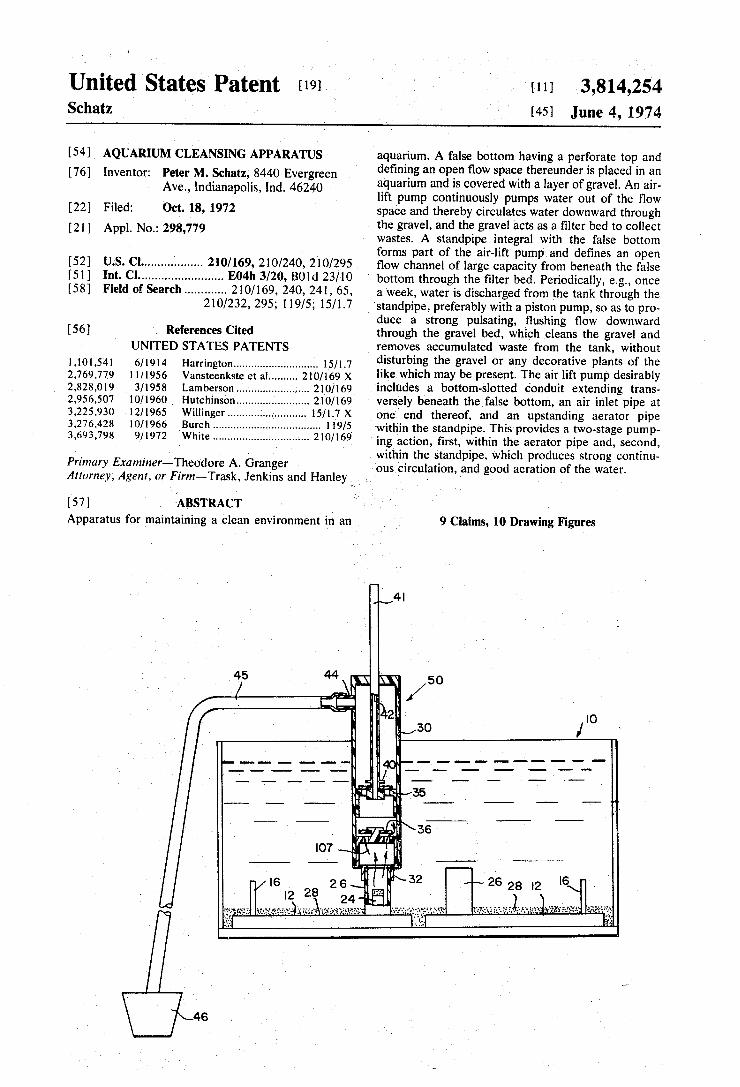
FIG. 1 is a longitudinal sectional view showing the general arrangement of a domestic aquarium contain ing two modular 10 inch X 10 inch false bottoms in ac cordance with my invention; FIG. 2 is an isometric view of a representative false
bottom, partially cut away; FIG. 3 is a sectional view showing the general ?ow of
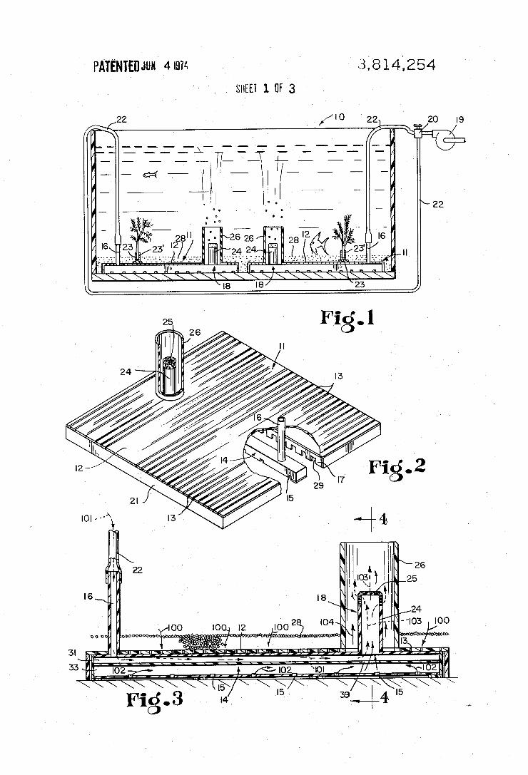
air and waterthrough the system; ' FIG. 4 is- a sectional view taken on the line 4--4 of
FIG. 3, and further showing the general ?ow of air and water through the system; ' FIG. 5 is a sectional view of the aquarium of FIG. I
with a suction piston pump connected with the stand pipe for periodically flushing the gravel bed; FIG. 6 is a bottom view of the air-lift pump manifold
showing bottom openings of graduated, rather than uniform, size; . '
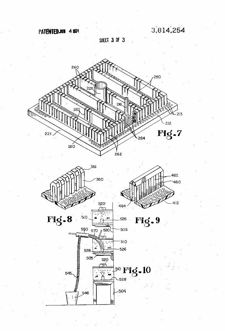
FIG. 7 is an isometric view of a modi?ed embodiment of a modular false bottom, with parts cut away;
FIG. 8 is a partial isometric view showing a modifica ' tion of the embodiment of FIG. 7; '
FIG. 9 is another partial isometric view showing a modi?cation of the embodiment of FIG. 7; and FIG. 10 is an end elevation of an aquarium display
arrangement showing a modi?cation in which the ' pump is connected by a ?exible tubing.
DETAILED DESCRIPTION OF THE PREFERRED EMBODIMENT
The aquarium 10 shown in FIG. 1 is a generally rect~ angular tank which contains two false bottom modules 11 resting on its bottom wall. The modules 11 each comprise a false bottom 12 spaced above the floor of the tank, which are covered with a gravel bed 28, and the aquarium I0 is ?lled with water. Each module 11 contains an air-lift pump 18 to which air is supplied through an air hose 22 from a gang valve 20 connected to an air pump 19 and provided with valves to allow for regulation of the air ?ow. ‘ The representative perforate false bottom module 11
shown in FIG. 2 has its false bottom I2 formed of a se ries of slats spaced from each other to de?ne interven ing slots 13 and supported approximately 1/2 inch above the bottom of the aquarium by a plurality of transverse ribs 17 and sidewalls 21. The transverse ribs 17 include a plurality of spaced notches-29 to provide open ?ow in the space beneath the false bottom 12. The height of the false bottom 12 above the ?oor of the aquarium should be sufficient to provide a substantially open space for water flow beneath the false bottom I2. The transverse slots 13 desirably form about 25 per
cent of the total surface area of the false bottom 12, and are of a small size to prevent passage of the gravel. A plurality of holes may serve the same purpose if pro vided in suf?cient size and number for adequate flow and to retain the gravel. An open standpipe 26 upstands from the false bottom
5
15
4 upward in the gravel bed for supporting arti?cial plants or other decorations in the aquarium independently of the gravel bed. '
The false bottom module can be formed from any of several materials, and is desirably produced by molding from a plastic material, as by injection molding.
In the operation of the module, a continuous down ward circulation of water through the gravel isdesired in order to carry ?sh wastes, excess food, and other de bris downward and into the gravel bed 28. The gravel bed 28 is suf?ciently deep, preferably at least about 1 inch, to allow the bed to function as a ?lter. Such downward circulation of water is achieved by means of the air-lift pump 18. The air-lift pump 18 of the module 11 includes conduit means disposed in the open flow space beneath the false bottom I2, as shown in FIG. 3, and comprises an air inlet pipe 16, a horizontalmani fold l4, and an aerator pipe 24. The horizontal mani fold 14 de?nes anupper air conduit 31 from the air inlet pipe 16 to the bottom of the aerator pipe 24, and de?nes a lower water conduit'33 leading to a port 39 immediately below the aerator pipe 24, and having a
’ series of spaced inlet openings 15 at its bottom side.
25
30
35
45
50
55
12 and de?nes a passage from the open flow space be- ' neath the false bottom 12, through the false bottom 12 and the gravel bed 28, and to an outlet above the gravel bed 28. The false bottom desirably carries several spaced
studs 23 to receive tubular receptacles 23' extending
65
The air inlet pipe 16 is connected, above the gravel bed, to the air hose 22 through which it is supplied with air under pressure from the pump 19. The air flows from the pipe 16 through the air conduit 31, as shown by the broken-line arrows 101 in FIG. 3, to the base of the aerator pipe 24, andthence upward through that aerator pipe. This causes water to be drawn through the port 39 from the conduit 33, which mixes with the air, and the resulting air-water mixture rises through the aerator pipe 24, as shown by the combined broken-line and solid-line arrows 103. Because water is drawn out of the water conduit 33 through the port 39, water is concurrently drawn from the open flow space beneath the false bottom 12 into the conduit 33 vthrough its lower inlet openings 15, as shown by solid-line arrows 102. The air-lift pump 18 thus produces a pumping ac tion from below the false bottom 12, into the water conduit 33, and up the aerator pipe 24 to the body of water above the gravel bed, which causes water to be continuously pulled downward over and through the gravel-bed 28, as shown by arrows 100. vDesirably, the aerator pipe 24 of the air-lift pump 18
is disposed within the standpipe 26, as shown in FIGS. 3 and 4, so as to produce a second stage of air-lift pumping action. For this purpose, the upper end of the aerator pipe 24 is located intermediate the height of the standpipe 26 and discharges to that standpipe through a plurality of small perforations 25. These serve to break up the air into small bubbles which rise through the standpipe 26, as shown by the arrows 103, and up ward therefrom through the body of water in the tank, as shown in FIG. I. This causes a further or secondary stage of air-lift pumping action in the standpipe 26, by which water is drawn upward into the standpipe 26, outside the aerator pipe 24 as shown by arrows 104, from beneath the false bottom 12, and upward to the body of water above. the gravel bed 28. The two stages of air-lift pumping action produce a
strong flow of water upward through the aerator pipe 24 and the standpipe 26 from below the gravel bed to above the gravelbed. This in turn causes a continuous general circulation of water downward through the gravel bed over the entire area thereof to - deposit wastes on and in the gravel bed 28. _
5 Periodically, for example, every 2 or 3 weeks, waste
materials that have been drawn into the gravel bed 28 by the continuous downward water circulation are re moved. It is an important feature of this invention to provide means for periodically removing the collected waste materials from the gravel bed 28 and from the aquarium, without disturbing the ?sh or the ?lter bed or other contents of the aquarium. Such removalof wastes is accomplished by withdrawing part of the water in the aquarium through the standpipe 26, so as to cause a ?ushing ?ow downward through the gravel bed 28 to the open flow space beneath the false bottom 12 and thence up the standpipe 26 and to a discharge conduit. This carries the accumulated wastes out of the gravel bed 28 to the discharge conduit without mixing the wastes with the main body of water in the aquar ium, and leaves that main body clean and clear. Effec tive cleaning can be accomplished by withdrawing say from one-fourth to one-third of the water in the tank. The water removed is of course replaced by clean wa ter. . ‘ .
The water withdrawal is preferably effected by a re ciprocating pump, which produces a pulsing flow through the gravel bed. A suction piston pump 50 is shown in FIG. 5 for the purpose of removing collected .waste materials from the gravel bed 28 and from the aquarium. The suction piston pump'50.shown com prises a cylinder 30 containing a piston 35 and having an end ?tting 32 adapted to ?t closely over the top of the standpipe 26. A piston rod 41 is attached to the pis ton 35 and is preferably hollow to form a vent passage 42 from the suction chamber of the pump 50. A lower check valve 36 is provided‘ on the end ?tting 32, and an upper check valve 40 is provided on the piston 35. Near the top of the cylinder 30, as shown in FIG. 5, is a hose connector 44, to which is connected a water line 45 terminating in a bucket 46 or the like. Desirably, the water line 45 may extend to a level below the aquar ium, so that the pump and the water line together form a siphon. -
In using the suction piston pump 50, the operator grasps the hollow piston rod 41 and closes the passage 42 with his thumb. He then pulls up on the piston rod 41 to lift the piston'and draw water upward from the standpipe 26 into the pump cylinder 30 past the lower check valve 36. By repeated up and down strokes of the piston rod 41, water is pumped upward through the standpipe 26, through the suction piston pump 50, and through the hose connector 44 and water line 45 to the bucket 46.
Desirably, the suction piston pump 50 is operated at
3,814,254
20
25
30
35
50
least initially in a series of sharp and rapid strokes. This . produces a strong, pulsating water flow upward through the standpipe 26 and hence downward through the gravel bed 28 and the false bottom 12. The strong, pulsating water ?ow downward through the gravel bed 28 acts to dislodge accumulated wastes therefrom and to flush them through the standpipe 26 and the pump 50, and to discharge them into‘ the bucket 46. A strong siphon'?ow through the piston pump 50
shown in FIG. 5 is induced by positioning the'bucket 46 containing the discharge end of the water line 45 hori zontally below the tank 10, as shown. -With this ar rangement, two or three sharp strokes of the pump 50 will dislodge the wastes from the gravel bed and initiate siphon flow through the pump 50 and the waterline 45. Such a siphon flow may be suf?cient to complete the
55
60
65
6 desired ?ushing of accumulated waste materials from the gravel bed 28, without further pumping. When suf ?cient ?ushing ?ow has occurred, the operator breaks the siphon flow by removing his thumb from the pas sage 42 of the hollow piston rod 41. The pump ?ow and the siphon ?ow described above
remove wastes from the gravel and discharge the waste materials outside the aquarium without mixing them with the main body of water in the aquarium, so that the main body remains clear. Adequate ?ow passage areas should be provided
through the false bottom 12 and the standpipe 26 in order to permit the desired strong ?ushing flow through the gravel bed 28. Desirably, the false bottom surface area includes at least about 25 percent open area. A 10 inch by 10 inch false bottom is desirably provided with an open standpipe de?ning an effective pump suction area of at least about 0.75 square inch and preferably 1.00 square inch. The effective pump suction area can be de?ned as the open area of the standpipe, that is, the cross-sectional area of the standpipe less the area occu pied by the aerator pipe' disposed therein. For example, a 10 inch by 10 inch false bottom having a 1.25 square inch standpipe with a 0.25 square inch aerator pipe dis posed therein has an effective pump suction area of 1.00 square inch, which is 1 percent of the false bottom surface area. If the aerator pipe were omitted, as when water circulation is provided by some other means, then the effective pump suction area would be the full open area of the standpipe. The suction piston pump may be constructed from
any of several materials, desirably, of a lightweight, in expensive plastic. Preferably, the walls are transparent to allow the operator to see the material ?owing through the pump. When the water inside the pump be comes clear, the operator knows that the gravel bed has been ?ushed. ' FIG. 6 shows a modi?ed form of aerator manifold.
The manifold 14’, shown in a bottom view, has its aera tor pipe 24' centered between its ends, for use with a false bottom module as in FIG. 7 in which the standpipe is in the center. Its air inlet pipe 16’ is at one end. Like the manifold of FIG. 3,it has an upper air conduit lead ing from the air inlet pipe 16' to the aerator pipe 24’. It also has a lower water conduit having an outlet port 39’ leading to the aerator pipe 24', and has suction inlet openings 15' in its bottom wall. In this modi?ca tion, the suction openings 15' are in the form of perfo< rations of graduated size, with the largest at the greatest distance from the outlet port 39'. This provides a distri- ‘ bution of inlet ?ow different from that of the manifold of FIG. 3. .
A modi?ed false bottom module is shown in FIG. 7. This modi?cation comprises a false bottom or platform 212 joined to supporting sidewalls 221 and supported at intermediate points by ribs or posts or other sup ports. The platform 212 has a central standpipe 226 containing an aerator 'pipe (now shown) connected to an air inlet pipe 216 by a manifold such as that shown in FIG. 6. The platform 212 carries a pattern of up standing ribs 260 de?ned by side and-top walls which form downward open channels 264 communicating
' with the open ?ow space beneath the false bottom 212. To provide for downward ?ow to» the ?ow space, the false bottom or platform 212 contains a plurality of perforations 213, and the ribs 260 are formed with spaced slots 262. In use, the ribs 260 project upward
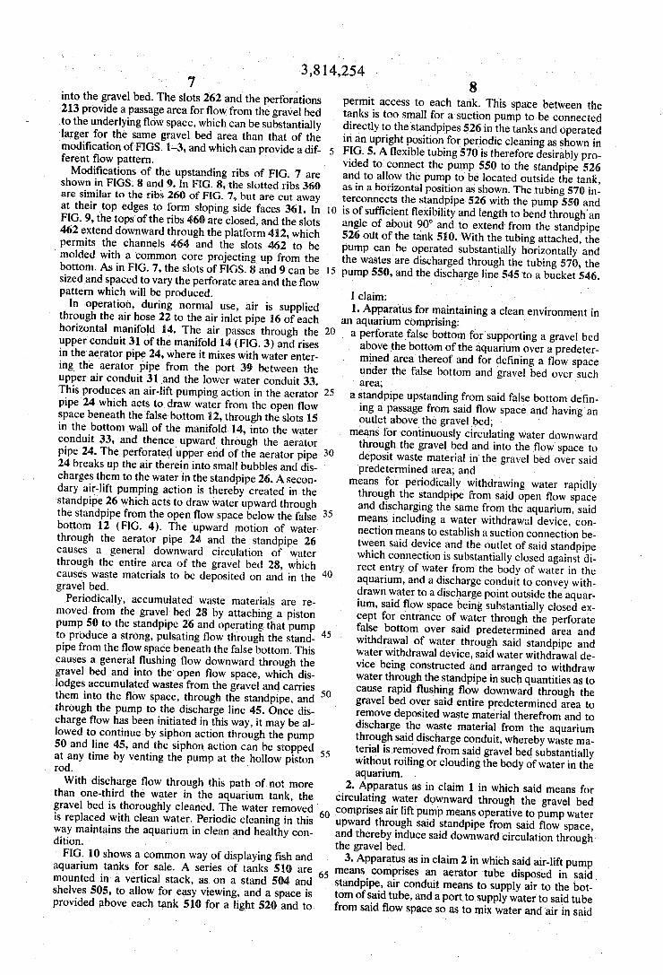
3,814,254 7
into the gravel bed. The slots 262'and the perforations 213 provide a passage area for ?ow from the gravel bed to the underlying flow space, which can be substantially larger for the same gravel bed area than that of the modi?cation of FIGS. 1-3, and which can provide a dif ferent ?ow pattern. '
Modi?cations of the upstanding ribs of FIG. 7 are shown in FIGS. 8 and 9. In FIG. 8, the slotted ribs 360 are similar to the ribs 260 of FIG. 7, but are cut away at their top edges to form sloping side faces 361. In FIG. 9, the tops of the ribs 460 are closed, and the slots 462 extend downward through the platform 412, which permits the channels 464 and the slots 462 to be
‘ molded with a common core projecting up from the bottom. As in FIG. 7, the slots of FIGS. 8 and 9 can be sized and spaced to vary the perforate area and the ?ow pattern which will be produced. .
In operation, during normal use, air is supplied through the air hose 22 to the air inlet pipe 16 of each horizontal manifold 14. The air, passes through the upper conduit 31 of the manifold 14 (FIG. 3) and rises in the aerator pipe 24, where it mixes with water enter ing the aerator pipe from the port 39 between the upper air conduit 31 ‘and the lower water conduit 33. This produces an air-lift pumping action in the aerator pipe 24 which acts to draw water from the open ?ow space beneath the false bottom 12, through the slots 15
20
2 LII
in the bottom wall of the manifold 14, into the water - conduit 33, and thence upward through the aerator pipe 24. The perforated upper end of the aerator pipe 24 breaks up the air therein into small bubbles and dis charges them to the water in the standpipe 26. A secon dary air-lift pumping action is thereby created in the standpipe 26 which acts to draw water upward through the standpipe from the open ?ow space below the false bottom 12 (FIG. 4). The upward motionof water through the aerator pipe 24 and the standpipe 26 causes a general downward circulation of water through the entire area of the gravel bed 28, which causes waste materials to be deposited on and in the gravel bed.
Periodically, accumulated waste materials are re moved from the gravel bed 28 by attaching a piston pump 50 to the standpipe 26 and operating that pump to produce a strong, pulsating flow through the stand pipe from the ?ow space beneath the false bottom. This causes a general ?ushing flow downward through the gravel bed andinto the open flow space, which dis lodges accumulated wastes from the gravel and carries them into the flow space, through the standpipe, and
' through the pump to the discharge line 45. Once dis charge flow has been initiated in this way, it may be al lowed to continue by siphon action through the pump 50 and line 45, and the siphon action can be stopped at any time by venting the pump at the hollow piston rod. With discharge ?ow through this path of not more
than one-third the water in the aquarium tank, the gravel bed is thoroughly cleaned. The water removed ' is replaced with clean water. Periodic cleaning in this way maintains the aquarium in clean and healthy con dition. - '
FIG. 10 shows a common way of displaying ?sh and aquarium tanks for sale. A series of tanks 510 are mounted in a vertical stack, asv on a stand 504 and shelves 505, to allow for easy viewing, and a space is provided above each tank 510 for a light 520 and to
30
35
45
50
60
65
8 permit access to each tank. This space between the tanks is too small for a suction pump to be connected directly to the standpipes 526 in the tanks and operated in an upright position for periodic cleaning as shown in FIG. 5. A ?exible tubing 570 is therefore desirably pro vided to connect the pump 550 to the standpipe 526 and to allow the pump to' be located outside the tank, as in a horizontal position as shown. The tubing 570 in terconnects the standpipe‘ 526 with the pump 550 and is of suf?cient ?exibility and length to bend through'an angle of about 90° and to extend from the standpipe 526 out of the tank 510. With the tubing attached, the pump can be operated substantially horizontally and the wastes are discharged through the tubing 570, the pump 550, and the discharge line 545 ‘to a bucket 546.
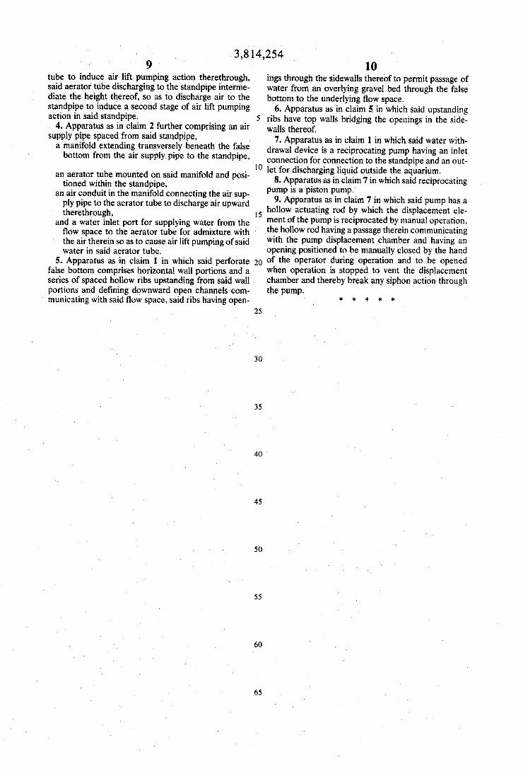
I claim: .
1. Apparatus for maintaining a clean environment in an aquarium comprising: .
a perforate false bottom for'supporting a gravel bed above-the bottom of the aquarium over a predeter mined area thereof and for de?ning a flow space under the false bottom and gravel bed over such area;
a standpipe upstanding from said false bottom de?n ing a passage from said flow space and having an outlet above the gravel bed; .
means for. continuously circulating water downward through the gravel bed and into the ?ow space to deposit waste material in the gravel bed over said predetermined area; and
means for periodically withdrawing water rapidly through the standpipe from said open ?ow space and discharging the same from the aquarium, said means including a water withdrawal device. con nection means to establish a suction connection be tween said device and the outlet of said standpipe which connection is substantially closed against di rect entry of water from the body of water in the aquarium, and a discharge conduit to convey with drawn water to a discharge point outside the aquar ium, said ?ow space being substantially closed ex cept for entrance of water through the perforate false bottom over said predetermined area and withdrawal of water through said standpipe and water withdrawal device, said water withdrawal de vice being constructed and arranged to withdraw water through the standpipe in such quantities as to cause rapid ?ushing ?ow downward through the gravel bed over said entire predetermined area to remove deposited waste material therefrom and to discharge the waste material from the aquarium through said discharge conduit, whereby waste ma terial is removed from said gravel bed substantially without roiling or clouding the body of water in the aquarium. ’
2. Apparatus as in claim 1 in which said means for circulating water downward through the gravel bed comprises air lift pump means operative to pump water upward through said standpipe from said flow space, and thereby induce said downward circulation through the gravel bed.
3. Apparatus as in claim 2 in which said air-lift pump means comprises an aerator tube disposed in said standpipe, air conduit means to supply air to the bot tom of said tube, and a port tosupply water to said tube from said flow space so as to mix water and air in said
3,814,254 9
tube to induce air lift pumping action therethrough, said aerator tube discharging to the standpipe interme diate the height thereof, so as to discharge air to the standpipe to induce a second stage of air lift pumping action in said standpipe.
4. Apparatus as in claim 2 further comprising an air supply pipe spaced from said standpipe, V a manifold extending transversely beneath the false bottom from the air supply. pipe to the standpipe,
an aerator tube mounted on said manifold and posi tioned within the standpipe,
an air conduit in the manifold connecting the air sup ply pipe to the aerator tube to discharge air upward therethrough,
and a water inlet port for supplying water from the ?ow space to the aerator tube for admixture with the air therein so as to cause air lift pumping of said water in said aerator tube.
5. Apparatus as in claim 1 in which said perforate false bottom comprises horizontal wall portions and a series of spaced hollow ribs upstanding from said wall portions and de?ning downward open channels com municating with said ?ow space, said ribs having open
5
20
25
30
35
45
50
55
65
10 ings through the sidewalls thereof to permit passage vof water from an overlying gravel bed through the false bottom to the underlying ?ow space.
6. Apparatus as in claim 5 in which said upstanding ribs have top walls bridging the openings in the side walls thereof.
7. Apparatus as in claim 1 in which said water with drawal device is a reciprocating pump having an inlet connection for connection to the standpipe and an out let for discharging liquid outside the aquarium.
8. Apparatus as in claim 7 in which said reciprocating pump is a piston pump.
9. Apparatus as in claim 7 in which said pump has a hollow actuating rod by ‘which the displacement ele ment of the pump is reciprocated by manual operation, the hollow rod having a passage therein communicating with the pump displacement chamber and having an opening positioned to be manually closed by the hand of the operator during operation and to be opened when operation is stopped to vent the displacement chamber and thereby break any siphon action through the pump.
*****


![[eBook] - Aquarium - The Reef Aquarium - Vol.2](https://img.pdfslide.us/doc/110x75/55cf9a7c550346d033a1f4a6/ebook-aquarium-the-reef-aquarium-vol2-5659d8cb10278.jpg)


![[eBook] - Aquarium - The Reef Aquarium - Vol.1](https://img.pdfslide.us/doc/110x75/55cf988e550346d033984c0f/ebook-aquarium-the-reef-aquarium-vol1.jpg)