Embed Size (px)
Citation preview

AQ150Thermostatic bar mixer valvewith adjustable head
Installation guide
AQ150:Midas 15/9/15 12:15 Page 1
2
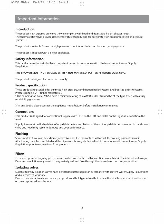
IntroductionThe product is an exposed bar valve shower complete with fixed and adjustable height shower heads.The thermostatic valves provide close temperature stability and fail safe protection on appropriate high pressuresystems.
The product is suitable for use on high pressure, combination boiler and boosted gravity systems.
The product is supplied with a 5 year guarantee.
Safety informationThis product must be installed by a competent person in accordance with all relevant current Water SupplyRegulations.
THE SHOWER MUST NOT BE USED WITH A HOT WATER SUPPLY TEMPERATURE OVER 65ºC.
The product is designed for domestic use only.
Product specificationThese products are suitable for balanced high pressure, combination boiler systems and boosted gravity systems.Pressure range 1.0* – 10 bar max (static).* The combination boiler MUST have a minimum rating of 24kW (80,000 Btu) and be of the type fitted with a fullymodulating gas valve.
If in any doubt, please contact the appliance manufacturer before installation commences.
ConnectionsThis product is designed for conventional supplies with HOT on the Left and COLD on the Right as viewed from thefront.
Supply lines must be flushed clear of any debris before installation of the unit. Any debris accumulation in the showervalve and head may result in damage and poor performance.
FlushingSome modern fluxes can be extremely corrosive and, if left in contact, will attack the working parts of this unit.All soldering must be completed and the pipe work thoroughly flushed out in accordance with current Water SupplyRegulations prior to connection of the product.
FiltersTo ensure optimum ongoing performance, products are protected by inlet filter assemblies in the internal waterways.Debris accumulation may result in progressively reduced flow through the showerhead and noisy operation.
Isolating valvesSuitable full way isolation valves must be fitted to both supplies in accordance with current Water Supply Regulationsand our terms of warranty.Due to their restrictive characteristics, stopcocks and ball type valves that reduce the pipe bore size must not be usedon gravity pumped installations.
Important information
AQ150:Midas 15/9/15 12:15 Page 2
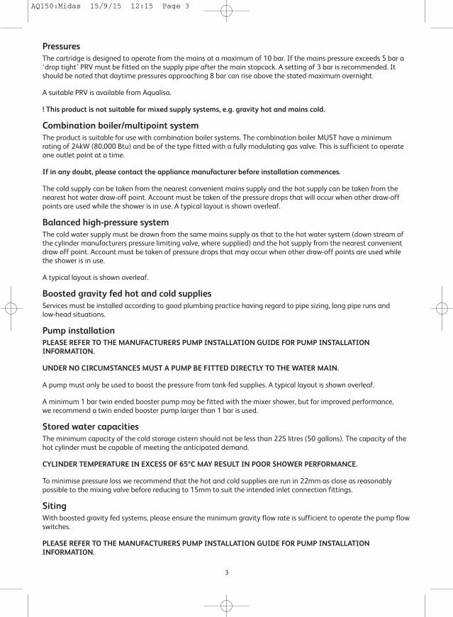
PressuresThe cartridge is designed to operate from the mains at a maximum of 10 bar. If the mains pressure exceeds 5 bar a‘drop tight’ PRV must be fitted on the supply pipe after the main stopcock. A setting of 3 bar is recommended. Itshould be noted that daytime pressures approaching 8 bar can rise above the stated maximum overnight.
A suitable PRV is available from Aqualisa.
! This product is not suitable for mixed supply systems, e.g. gravity hot and mains cold.
Combination boiler/multipoint systemThe product is suitable for use with combination boiler systems. The combination boiler MUST have a minimumrating of 24kW (80,000 Btu) and be of the type fitted with a fully modulating gas valve. This is sufficient to operateone outlet point at a time.
If in any doubt, please contact the appliance manufacturer before installation commences.
The cold supply can be taken from the nearest convenient mains supply and the hot supply can be taken from thenearest hot water draw-off point. Account must be taken of the pressure drops that will occur when other draw-offpoints are used while the shower is in use. A typical layout is shown overleaf.
Balanced high-pressure systemThe cold water supply must be drawn from the same mains supply as that to the hot water system (down stream ofthe cylinder manufacturers pressure limiting valve, where supplied) and the hot supply from the nearest convenientdraw off point. Account must be taken of pressure drops that may occur when other draw-off points are used whilethe shower is in use.
A typical layout is shown overleaf.
Boosted gravity fed hot and cold suppliesServices must be installed according to good plumbing practice having regard to pipe sizing, long pipe runs andlow-head situations.
Pump installationPLEASE REFER TO THE MANUFACTURERS PUMP INSTALLATION GUIDE FOR PUMP INSTALLATIONINFORMATION.
UNDER NO CIRCUMSTANCES MUST A PUMP BE FITTED DIRECTLY TO THE WATER MAIN.
A pump must only be used to boost the pressure from tank-fed supplies. A typical layout is shown overleaf.
A minimum 1 bar twin ended booster pump may be fitted with the mixer shower, but for improved performance,we recommend a twin ended booster pump larger than 1 bar is used.
Stored water capacitiesThe minimum capacity of the cold storage cistern should not be less than 225 litres (50 gallons). The capacity of thehot cylinder must be capable of meeting the anticipated demand.
CYLINDER TEMPERATURE IN EXCESS OF 65ºC MAY RESULT IN POOR SHOWER PERFORMANCE.
To minimise pressure loss we recommend that the hot and cold supplies are run in 22mm as close as reasonablypossible to the mixing valve before reducing to 15mm to suit the intended inlet connection fittings.
SitingWith boosted gravity fed systems, please ensure the minimum gravity flow rate is sufficient to operate the pump flowswitches.
PLEASE REFER TO THE MANUFACTURERS PUMP INSTALLATION GUIDE FOR PUMP INSTALLATIONINFORMATION.
3
AQ150:Midas 15/9/15 12:15 Page 3
4
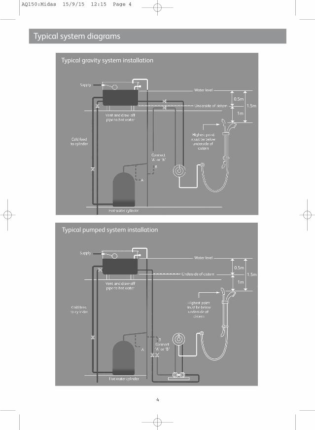
Typical system diagrams
Typical pumped system installation
Typical gravity system installation
0.5m
1m
1.5m
0.5m
1m
1.5m
Water level
Water level
AQ150:Midas 15/9/15 12:15 Page 4
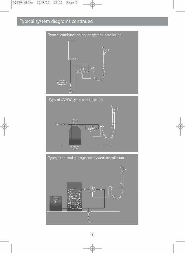
Typical system diagrams continued
Typical combination boiler system installation
Typical thermal storage unit system installation
Typical UVHW system installation
5
AQ150:Midas 15/9/15 12:15 Page 5
6
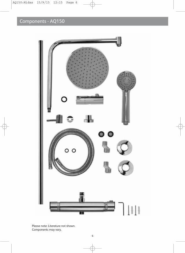
Please note: Literature not shown.Components may vary.
Components - AQ150
AQ150:Midas 15/9/15 12:15 Page 6
Aqualisa bar valve installation
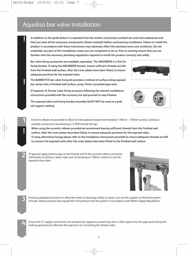
2 If required, apply jointing tape to the threads and fit the eccentric elbow connectorssufficiently to achieve a water tight seal, terminating at 150mm centres to suit theexposed valve inlets.
7
Eccentric elbows are provided to allow for inlet pipework adjustment between 130mm – 170mm centres. Construct
suitable connections terminating in ½”BSP female fittings.
When using the eccentric elbows provided we recommend leaving sufficient threads from the finished wall
surface, after the cover plates have been fitted, to ensure adequate purchase for the exposed valve.
If using alternative fixings please refer to the installation instructions provided to ensure adequate threads are left
to connect the exposed valve after the cover plates have been fitted to the finished wall surface.
1
!
3 Ensuring adequate provision to allow the water to discharge safely to waste, turn on the supplies to flush the systemthrough. Attach pressure test equipment and pressure test the system in accordance with Water Supply Regulations.
4 Ensure the ¾” supply connections are temporarily capped to prevent any dirt or dust ingress into the pipe work during themaking good process. Remove the caps prior to connecting the shower valve.
!
!
In addition to the guide below it is essential that the written instructions overleaf are read and understood and
that you have all the necessary components (shown overleaf) before commencing installation. Failure to install the
product in accordance with these instructions may adversely affect the warranty terms and conditions. Do not
undertake any part of this installation unless you are competent to do so. Prior to starting ensure that you are
familiar with the necessary plumbing regulations required to install the product correctly and safely.
Bar valve fixing accessories are available separately. The MD300EFB is a first fix
fixing bracket. If using the MD300EFB bracket, ensure sufficient threads are left
from the finished wall surface, after the cover plates have been fitted, to ensure
adequate purchase for the exposed valve.
The BAR001FIX bar valve fixing kit provides a method of surface siting exposed
bar valves onto a finished wall surface, using 15mm concealed pipe work.
If required, fit the bar valve fixing accessory following the relevant installation
instructions provided with the accessory kit and proceed to step 6 below.
The exposed valve and fixing bracket assembly MUST NOT be used as a grab
rail support method.
AQ150:Midas 15/9/15 12:15 Page 7
6 Ensuring the washers are positioned within the valve inlets, offer the valve into position. Tighten thefixing nuts using a suitable tool taking care not to overtighten.
8
5 Place the cover plates onto the exposed ¾” threads, flush with the finished wall surface and apply a thin bead of mastic if re-quired.
1 Ensuring the handset cradle is on the left hand side of the rail, pass the rail through the handsetholder whilst keeping the slider button depressed.
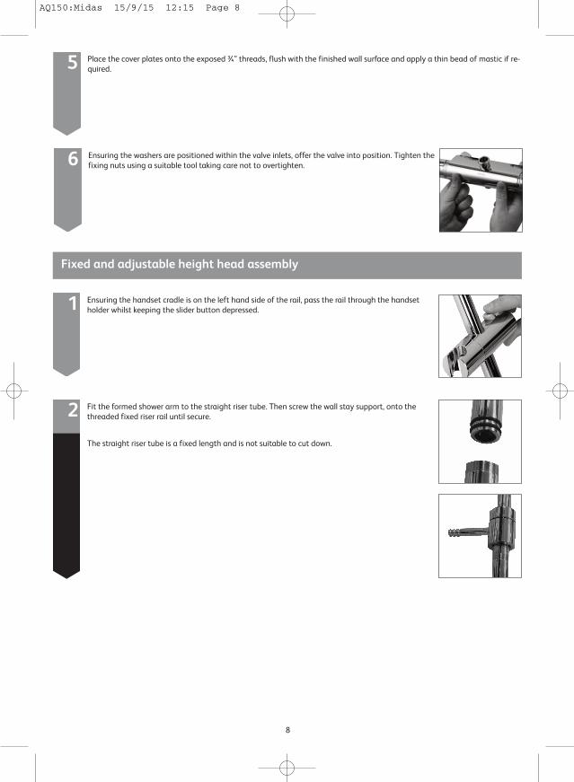
2 Fit the formed shower arm to the straight riser tube. Then screw the wall stay support, onto thethreaded fixed riser rail until secure.
The straight riser tube is a fixed length and is not suitable to cut down.
Fixed and adjustable height head assembly
AQ150:Midas 15/9/15 12:15 Page 8

3 Push the riser tube onto the valve top outlet and push fully home.
4 Carefully mark out the screw holes for the wall fixing bracket ensuring it is in the correct position to accept the fixed riserwall stay support.
5 Screw the wall fixing bracket to the wall using the screws provided.Place the cover plate over the wall fixing bracket.
9
6 Insert the lever of the wall stay support into the wall fixing bracket.
7 Carefully tighten the grub screw with the Allen key provided until secure.
AQ150:Midas 15/9/15 12:15 Page 9
10
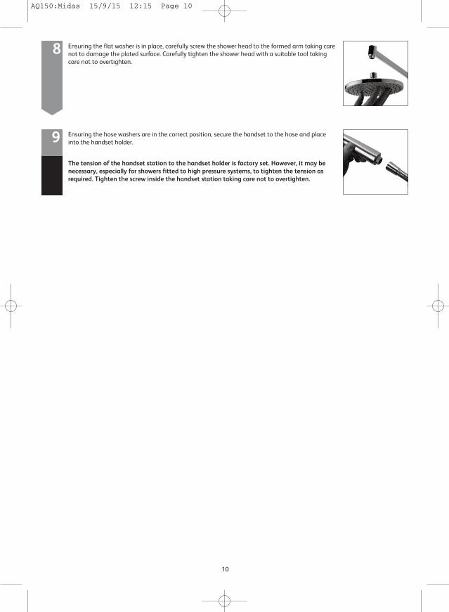
8 Ensuring the flat washer is in place, carefully screw the shower head to the formed arm taking carenot to damage the plated surface. Carefully tighten the shower head with a suitable tool takingcare not to overtighten.
9 Ensuring the hose washers are in the correct position, secure the handset to the hose and placeinto the handset holder.
The tension of the handset station to the handset holder is factory set. However, it may benecessary, especially for showers fitted to high pressure systems, to tighten the tension asrequired. Tighten the screw inside the handset station taking care not to overtighten.
AQ150:Midas 15/9/15 12:15 Page 10

11
Action
Check that the suppliescorrespond with the inletmarkings
Check the flow rate
recommendations with
the heater manufacturer
Adjust the flow control knob on
the mixer valve to reduce flow
until a comfortable showering or
bathing temperature is achieved
Symptom
Water output is either all hot or
all cold, or cold only
Possible cause
Reversed inlet supplies
Check that the pipe work is laid
out in accordance with correct
practices, paying particular
attention to potential air-traps
If the static water pressure
exceeds 10 bar, install a pressure
reducing valve (PRV) in
accordance with the installation
guide
Airlock in the hot water
supply
Water temperature swings
regularly between hot and cold
Flow rate is poor and water
temperature is low
Cold water pressure is too high
Poor flow rate Twisted hose
Debris in shower head
Debris in filters
Check for debris and clear as
necessary
The temperature of the hot
water cylinder is too low
Water output is not hot
enough
The cylinder temperature
should be at least 15˚C
hotter than the blend
Water flow through the hot
water appliance is too fast
Water flow through the hot
water appliance is too fast
(If fitted on a combination
boiler)
Trouble shooting guide
AQ150:Midas 15/9/15 12:15 Page 11
Aqualisa Products Limited
The Flyer’s Way
Westerham Kent TN16 1DE
Customer helpline: 01959 560010
Brochure Hotline: 0800 652 3669
Website: www.aqualisa.co.uk
Email: [email protected]
Republic of Ireland
Sales enquiries: 01-864-3363
Service enquiries: 01-844-3212
Please note that calls may be recorded for training and quality purposes
The company reserves the right to alter, change or modify the product specifications without prior warning
® Registered Trademark Aqualisa Products Limited
Part No: 701843 Issue 01 Aug 15
AQ150:Midas 15/9/15 12:15 Page 12