Embed Size (px)
Citation preview

QuartzDigitalRemote controls
Installation guide
TM
Quartz Digital remote control installation instructions Page 1

Quartz Digital remote control installation instructions Page 2
Quartz Digital remote control
QZD.B3.DS.14
Quartz Digital Divert remote control
QZD.B3.DVDS.14
Quartz Digital wireless remote
QZD.B3.WR.14
Quartz Digital Divert wireless remote
QZD.B3.DVWR.14
Quartz Digital remotes
Quartz Digital Divert remotes

Quartz Digital remote control installation instructions Page 3
Components - Quartz Digital remote control
Literature not
shown
Components - Quartz Digital wireless remote
Literature notshown

Quartz Digital remote control installation instructions Page 4
Important informationThe Quartz Digital wired secondary remote control is a remote button which provides a secondary method of
‘Start/stop’ for Quartz Digital shower systems. When used with the Quartz Digital diverter system, the remote can
operate each outlet by pushing and holding the ‘Start/stop’ button for a few seconds as required. The wired secondary
remote control may be sited inside the showering area, as long as it is not subjected to continuous spray, or it can be
sited outside the showering area – up to 10 metres from the Digital processor.
Quartz Digital wireless remote controls provide a secondary method of ‘Start/stop’ to the Quartz Digital product
controllers. When used with the Quartz Digital diverter system, the remote can operate each outlet by pushing and
holding the ‘Start/stop’ button for a few seconds as required. The wireless remote control may be sited inside the
showering area, as long as it is not subjected to continuous spray, or it can be sited outside the showering area.
Quartz Digital wireless remote controls can operate from up to 10m away from the receiver box which is plugged
into the main processor unit.
ENSURE THE CORRECT DIVERT OR NON-DIVERT VERSION IS SELECTED AND USED WITH THE RELEVANT
DIVERT OR NON-DIVERT SHOWER SYSTEMS. DIVERT REMOTES ARE NOT COMPATIBLE WITH NON-DIVERT
SYSTEMS AND VICE VERSA.
The Quartz Digital remote controls are not suitable for use with any other Aqualisa Digital product range.
THIS PRODUCT MUST BE INSTALLED BY A COMPETENT PERSON IN ACCORDANCE WITH ALL RELEVANT CURRENT
WATER AND ELECTRICAL SUPPLY REGULATIONS.
ALL SHOWERS REQUIRING AN ELECTRICAL CONNECTION MUST BE INSTALLED BY A QUALIFIED PERSON
FOLLOWING THE LATEST REVISION OF BS7671 (WIRING REGULATIONS) AND CERTIFIED TO CURRENT BUILDING
REGULATIONS.
Wireless products include a CR2450 battery, the replacement battery is available from Aqualisa Customer Service
Department, part no: 910197. Any product problems that may arise should the incorrect replacement battery be used
will not be covered by the terms of our guarantee.
This product is supplied complete with a 2 year guarantee.
The wireless remote battery is not covered by the terms of this guarantee.
This product is suitable for domestic use only..

Quartz Digital remote control installation instructions Page 5
Installation instructions
Quartz Digital remote control
In addition to the guide below it is essential that the written instructionsbelow are read and understood and that you have all the necessarycomponents (shown below) before commencing installation. Failure to installthe product in accordance with these instructions may adversely affect thewarranty terms and conditions. Do not undertake any part of this installationunless you are competent to do so. Prior to starting, ensure that you arefamiliar with the necessary plumbing regulations required to install theproduct correctly and safely.
THE DIGITAL PROCESSOR MUST BE ISOLATED FROM THE MAINS POWERSUPPLY PRIOR TO INSTALLING THE QUARTZ DIGITAL REMOTE CONTROL.
ENSURE THE CORRECT DIVERT OR NON-DIVERT VERSION IS SELECTEDAND USED WITH THE RELEVANT DIVERT OR NON-DIVERT SHOWERSYSTEMS. DIVERT REMOTES ARE NOT COMPATIBLE WITH NON-DIVERTSYSTEMS AND VICE VERSA.
!
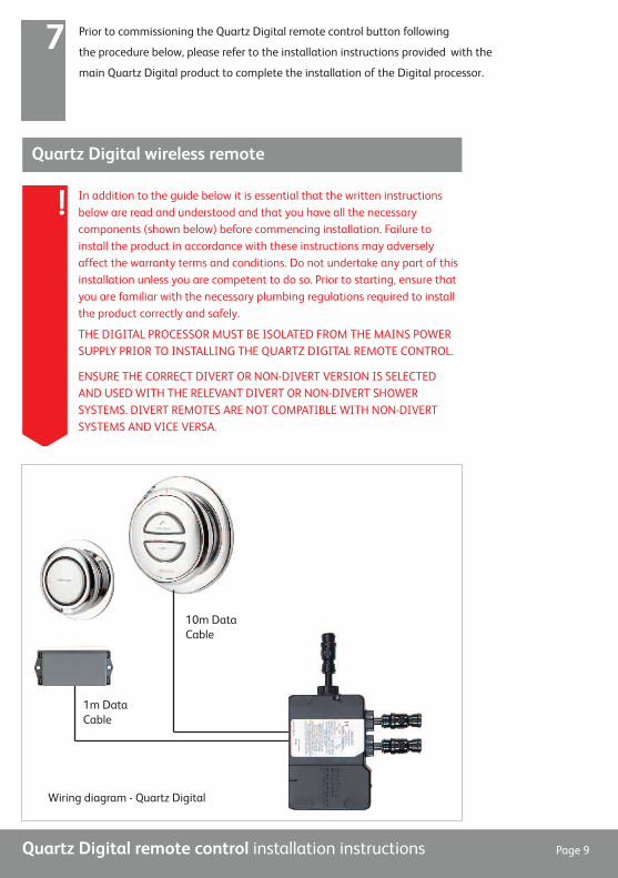
Wiring diagram - Quartz Digital
10m DataCable
10m DataCable

Quartz Digital remote control installation instructions Page 6
10m DataCable
10m DataCable
2m Data
Cable
Wiring diagram - Quartz Digital Divert
Using the back plate as a template, mark
the position of the fixing screws and a
Ø20mm hole for the data cable rear entry
point. Prepare suitable wall fixings to
accommodate no. 8 non-rusting
countersunk head screws of a suitable
length (not included).
1

Quartz Digital remote control installation instructions Page 7
Prepare a suitable route and install the 10m low voltage data cable leaving
a working end of at least 70mm including the connector plug. The end of
the data cable closest to the processor should terminate at a maximum
of 500mm from the processor to allow for connection to the data cable
connection block.
2
Apply a thin bead of silicone sealant in the
mastic groove at the rear of the mounting
plate and pull the data cable through before
securing the back plate to the wall using
suitable no. 8 non rusting countersunk
screws.
3
DATA CABLES MUST BE PROTECTED BY SUITABLE SHEATHING OR
CONDUIT IN THE EVENT OF SERVICING AND MAINTENANCE.
A CUT OUT IS PROVIDED IN THE BACK PLATE TO FACILITATE
SURFACE SITED CABLE ENTRY IF PREFERRED.
!
Lining up the key way, push the data cable
plug into the back of the button fully home,
using a flat bladed screwdriver or similar tool
if required, to ensure a water tight seal
making sure the seal is no longer visible.
4

Quartz Digital remote control installation instructions Page 8
Locate the button assembly onto the back
plate assembly with the ‘Start/stop’ or
‘Start/stop/divert’ graphic in the diagonal
position. Rotate the button clockwise so the
‘Start/stop’ or ‘Start/stop/divert’ graphic is
in the horizontal position to lock the button
in place.
5
To release the button, insert a small flat
bladed screw driver into the small opening
at the 7 o’clock position, to release the
locking mechanism, and rotate the button
anti-clockwise.
BEFORE ANY ELECTRICAL ADJUSTMENT IS
ATTEMPTED, THE ELECTRICITY SUPPLY
MUST BE TURNED OFF AT THE MAINS
SWITCH. ELECTRICAL INSTALLATION MAY
ONLY BE CARRIED OUT BY A QUALIFIED
PERSON.
!
The Digital processor features a secondary
data cable socket next to the main data
cable connection for use with the Digital
remote control secondary ‘Start/stop’
button. Carefully snap and remove the
entry pillar and connect the cable into the
socket as shown.
6
For Divert secondary ‘Start/stop’ remotes, the cable plugs into the diverter.
If using with a Divert product, refer to the Divert installation instructions.!
Quartz Digital remote control installation instructions Page 9
Prior to commissioning the Quartz Digital remote control button following
the procedure below, please refer to the installation instructions provided with the
main Quartz Digital product to complete the installation of the Digital processor.
7
Quartz Digital wireless remote
In addition to the guide below it is essential that the written instructionsbelow are read and understood and that you have all the necessarycomponents (shown below) before commencing installation. Failure toinstall the product in accordance with these instructions may adverselyaffect the warranty terms and conditions. Do not undertake any part of thisinstallation unless you are competent to do so. Prior to starting, ensure thatyou are familiar with the necessary plumbing regulations required to installthe product correctly and safely.
THE DIGITAL PROCESSOR MUST BE ISOLATED FROM THE MAINS POWERSUPPLY PRIOR TO INSTALLING THE QUARTZ DIGITAL REMOTE CONTROL.
ENSURE THE CORRECT DIVERT OR NON-DIVERT VERSION IS SELECTEDAND USED WITH THE RELEVANT DIVERT OR NON-DIVERT SHOWERSYSTEMS. DIVERT REMOTES ARE NOT COMPATIBLE WITH NON-DIVERTSYSTEMS AND VICE VERSA.
!
Wiring diagram - Quartz Digital
1m DataCable
10m DataCable

Quartz Digital remote control installation instructions Page 10
Using the back plate as a template, mark the
position of the fixing screws.1
10m DataCable
1m Data Cable
2m Data
Cable
Wiring diagram - Quartz Digital Divert

Replace the battery cover turning it a quarter
turn to lock in place.5
Quartz Digital remote control installation instructions Page 11
Drill and prepare the fixing points using the
fixings supplied, if suitable. Fit the wall plate onto
the back plate taking care to line up the location
slots on the back plate, and then fit the assembly
onto the wall.
2
Using a large flat bladed screwdriver, carefully
undo the battery cover by turning it a quarter
turn.
3
Place the CR2450 battery, positive side facing up,
into the rear of the wireless remote control.
(The positive side of the battery is the widest side,
with the imprinted written details).
4

Quartz Digital remote control installation instructions Page 12
Locate the button assembly onto the back
plate assembly with the ‘Start/stop’ or
‘Start/stop/divert’ graphic in the
horizontal position. Insert the top edge
first then carefully click the bottom into
position.
6
If required, to release the button, insert a small flat
bladed screwdriver into the small opening at the 6
o’clock position, to release the locking mechanism
and then pull the bottom of the button forwards.
BEFORE ANY ELECTRICAL ADJUSTMENT IS
ATTEMPTED, THE ELECTRICITY SUPPLY MUST BE
TURNED OFF AT THE MAINS SWITCH.
ELECTRICAL INSTALLATION MAY ONLY BE CARRIED
OUT BY A QUALIFIED PERSON.
!
The Digital processor features a secondary data
cable socket next to the main data cable connection.
Carefully snap and remove the entry pillar and insert
the patch lead data cable into the socket as shown.
7
For Divert secondary ‘Start/stop’ remotes, the cableplugs into the diverter. If using with a Divert product,refer to the Divert installation instructions.
!

Quartz Digital remote control installation instructions Page 13
Insert the other end of the patch lead data cable
into the receiver box.8
Secure the receiver box to a flat horizontal
surface using suitable fixings.9
If required, the top of the receiver box can be removed by first removing the fixing
screws securing the receiver box to the flat surface. Disengage the two fixing lugs at
one end of the box and carefully lift the top clear.
!
Prior to commissioning the Quartz Digital wireless remote control following the
procedure below, please refer to the installation instructions provided with the main
Quartz Digital product to complete the installation of the Digital processor.
10

Aqualisa Products Limited
The Flyer’s Way
Westerham Kent TN16 1DE
Customer helpline: 01959 560010
Brochure Hotline: 0800 652 3669
Website: www.aqualisa.co.uk
Email: [email protected]
Republic of Ireland
Sales enquiries: 01-864-3363
Service enquiries: 01-844-3212 Part No.700998 Issue 01 Jan 14
Please note that calls may be recorded for training and quality purposes
The company reserves the right to alter, change or modify the product specifications without prior warning
® Registered Trademark Aqualisa Products Limited