Embed Size (px)
Citation preview

APX™ TWO-WAY RADIOS
APX 7000XEMODEL 1USER GUIDE
APX7000XE_M1_FrontCover.fm Page 1 Wednesday, March 27, 2013 7:04 PM

English
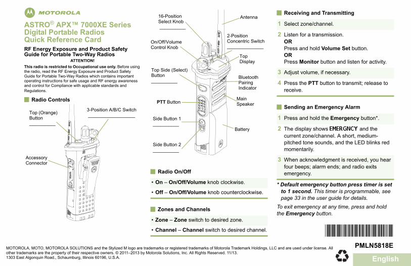
mASTRO® APX™ 7000XE Series Digital Portable RadiosQuick Reference CardRF Energy Exposure and Product Safety Guide for Portable Two-Way Radios
ATTENTION!This radio is restricted to Occupational use only. Before using the radio, read the RF Energy Exposure and Product Safety Guide for Portable Two-Way Radios which contains important operating instructions for safe usage and RF energy awareness and control for Compliance with applicable standards and Regulations.
Radio Controls
Radio On/Off
Zones and Channels
Receiving and Transmitting
Sending an Emergency Alarm
* Default emergency button press timer is set to 1 second. This timer is programmable, see page 33 in the user guide for details.
To exit emergency at any time, press and hold the Emergency button.
3-Position A/B/C Switch __________________
Accessory Connector
Top (Orange) Button__________
• On – On/Off/Volume knob clockwise.
• Off – On/Off/Volume knob counterclockwise.
• Zone – Zone switch to desired zone.
• Channel – Channel switch to desired channel.
Battery
Side Button 1__________
Side Button 2__________
PTT Button
On/Off/Volume Control Knob
16-Position Select Knob __________
Top Side (Select) Button__________
Main Speaker
Top Display
Antenna
2-Position Concentric Switch______________
Bluetooth Pairing Indicator
1 Select zone/channel.
2 Listen for a transmission.ORPress and hold Volume Set button.ORPress Monitor button and listen for activity.
3 Adjust volume, if necessary.
4 Press the PTT button to transmit; release to receive.
1 Press and hold the Emergency button*.
2 The display shows EMERGNCY and the current zone/channel. A short, medium-pitched tone sounds, and the LED blinks red momentarily.
3 When acknowledgment is received, you hear four beeps; alarm ends; and radio exits emergency.
*PMLN5818E*MOTOROLA, MOTO, MOTOROLA SOLUTIONS and the Stylized M logo are trademarks or registered trademarks of Motorola Trademark Holdings, LLC and are used under license. All other trademarks are the property of their respective owners. © 2011–2013 by Motorola Solutions, Inc. All Rights Reserved. 11/13. 1303 East Algonquin Road., Schaumburg, Illinois 60196, U.S.A.
PMLN5818E
APX_7000XE.book Page 3 Saturday, November 2, 2013 5:19 AM

English
Sending an Emergency Call
To exit emergency at any time, press and hold the Emergency button.
Sending a Silent Emergency Call
To exit emergency at any time, press and hold the Emergency button.
Display Status Icons
1 Press the Emergency button.
2 Press and hold the PTT button. Speak clearly into the microphone.
3 Release the PTT button to end call.
4 Press and hold Emergency button to exit emergency.
1 Press the Emergency button.
2 The display does not change; the LED does not light up, and there is no tone.
3 Silent emergency continues until you:Press and hold the Emergency button to exit emergency state.ORPress and release the PTT button to exit the Silent Emergency Alarm mode and enter regular dispatch or Emergency Call mode.
Blinks when the battery is low.
The more stripes, the stronger the signal strength for the current site (trunking only).
Direct radio to radio communication or connected through a repeater.On = DirectOff = Repeater
This channel is being monitored.
L = Radio is set at Low power.H = Radio is set at High power.
Scanning a scan list.
Blinking dot = Detects activity on the Priority-One Channel during scan.
Steady dot = Detects activity on the Priority-Two Channel during scan.
The vote scan feature is enabled.
On = Secure operation.Off = Clear operation.Blinking = Receiving an encrypted
voice call.
On steady = View modeBlinking = Program mode
UV
O
MHOR L
i
j
km
Basic Zone Bank 1A = Radio is in Zone 1.B = Radio is in Zone 2.C = Radio is in Zone 3.
Basic Zone Bank 2D = Radio is in Zone 4.E = Radio is in Zone 5.F = Radio is in Zone 6.
Enhanced Zone BankA = Contains Zone 1, Zone 2 and Zone
3,B = Contains Zone 4, Zone 5 and Zone
6,C = Contains Zone 7, Zone 8 and Zone
9,...X = Contains Zone 70, Zone 71 and
Zone 72,Y = Contains Zone 73, Zone 74 and
Zone 75.
Bluetooth is ready.
Bluetooth is connected to the device.
Aor
Bor
C
Dor
Eor
F
A, B,
C... ...
x or
y
ba
APX_7000XE.book Page 4 Saturday, November 2, 2013 5:19 AM

ContentsDeclaration of Conformity......................... 6
Important Safety Information........10
Software Version............................11Notice to Users (FCC and Industry
Canada)....................................................11
Consignes de sécuritéimportantes.................................12
Version logicielle........................... 13Avis aux utilisateurs (FCC et Industrie
Canada)....................................................13
Computer Software Copyrights....14
Documentation Copyrights...........15
Disclaimer.......................................16
Getting Started...............................17How to Use This Guide..................................17Notations Used in This Manual......................17Additional Performance Enhancement.......... 17
ASTRO 25 Enhanced Data.................17Dynamic System Resilience (DSR).... 17CrossTalk Prevention..........................18Encrypted Integrated Data (EID).........18SecureNet...........................................18Conventional Talkgroup and Radio
Scan Enhancements......................18What Your Dealer/System Administrator
Can Tell You.............................................19
Preparing Your Radio for Use.......20Charging the Battery......................................20Attaching the Battery..................................... 20
Contents
1
English

Attaching the Antenna................................... 21Removing and Attaching the Accessory
Connector Cover...................................... 22Attaching the Belt Clip................................... 23Turning On the Radio.................................... 24Adjusting the Volume.....................................25
Identifying Radio Controls............26Radio Parts and Controls...............................26Programmable Features................................27
Assignable Radio Functions............... 27Assignable Settings or Utility
Functions....................................... 30Accessing the Preprogrammed Functions.....30Push-To-Talk (PTT) Button............................30
Identifying Status Indicators.........32Status Icons...................................................32LED Indicator.................................................34Intelligent Lighting Indicators......................... 35Alert Tones.................................................... 37
General Radio Operation...............41
Selecting a Zone............................................41Selecting a Radio Channel............................ 41Receiving and Responding to a Radio Call... 41
Receiving and Responding to aTalkgroup Call................................41
Receiving and Responding to aPrivate Call (Trunking Only)...........42
Receiving and Responding to aTelephone Call (Trunking Only).....42
Making a Radio Call.......................................43Making a Talkgroup Call..................... 43
Switching Between Repeater or DirectOperation Button...................................... 44
Monitor Feature............................................. 44Monitoring a Channel..........................44Monitoring Conventional Mode........... 44
Advanced Features........................46Advanced Call Features................................ 46
Selective Call (ASTROConventional Only)........................ 46
Responding to the DynamicRegrouping Feature (TrunkingOnly).............................................. 46
Scan Lists...................................................... 47
Con
tent
s
2
English

Viewing a Scan List.............................48Viewing and Changing the Priority
Status.............................................48Scan...............................................................48
Turning Scan On or Off.......................48Making a Dynamic Priority Change
(Conventional Scan Only)..............48Deleting a Nuisance Channel............. 49Restoring a Nuisance Channel........... 49
Call Alert Paging............................................49Receiving a Call Alert Page................ 50
Emergency Operation....................................50Sending an Emergency Alarm............ 51Sending an Emergency Call
(Trunking Only).............................. 51Sending an Emergency Alarm with
Emergency Call............................. 52Sending a Silent Emergency Alarm.... 52Change of Channels during
Emergency.....................................53Emergency Keep-Alive Feature..........53
Fireground (Conventional Only).....................53Entering Fireground Zone Channel.....54Responding to Evacuation Indicator... 55
Tactical Public Safety(TPS) (ConventionalOnly)......................................................... 55
Using TPS Normal Transmission........55
Using TPS EmergencyTransmission................................. 56
Man Down......................................................56Pre-Alert Timer....................................58Post-Alert Timer..................................58Radio Alerts When Man Down
Feature is Triggered...................... 58Triggering Emergency.........................58Radio Alerts When Man Down
Enhanced is Triggered...................59Exiting Man Down Feature..................59Re-Initiating Man Down.......................60Testing the Man Down Feature...........60
Secure Operations.........................................60Selecting Secure Transmissions.........60Selecting Clear Transmissions........... 61Managing Encryption.......................... 61
Global Positioning System (GPS)..................64GPS Operation....................................64GPS Performance Enhancement........65Peer-Location on the Display
(ASTRO Conventional only).......... 65Trunking System Controls............................. 66
Using the Failsoft System................... 66Out-of-Range Radio............................67Site Trunking Feature......................... 67Locking and Unlocking a Site..............67
Contents
3
English

Site Display and Search Button.......... 67Mission Critical Wireless - Bluetooth®-.......... 68
Turning the Bluetooth On....................68Turning the Bluetooth Off....................69Re-Pair Timer......................................69Bluetooth Drop Timer..........................70Pairing with Low Frequency-
Motorola Proximity Pairing (LF-MPP) Feature................................ 71
Radio Indications of Lost BluetoothConnection.....................................72
Standard Pairing Feature....................72Turning On the Bluetooth Audio
(Routing the Audio from theRadio to the Headset)....................74
Turning Off the Bluetooth Audio(Routing the Audio from theHeadset to the Radio)....................75
Adjusting the Volume of the Radiofrom Bluetooth Audio Device......... 75
Clearing All Bluetooth DevicesInformation.....................................75
Programming Over Project 25 (POP 25)(ASTRO 25 and ASTRO Conventional)... 75
Voice Announcement.....................................76Site Selectable Alerts (ASTRO 25)................77Utilities........................................................... 77
Using the Flip Display......................... 77Selecting a Basic Zone Bank..............77Selecting an Enhanced Zone Bank.... 78Selecting the Power Level.................. 78Controlling the Display Backlight........ 79Locking and Unlocking the Controls... 79Turning Voice Mute On or Off.............79Using the Time-Out Timer...................80Using Conventional Squelch
Operation Features........................80Using the PL Defeat Feature.............. 81Digital PTT ID Support........................81Smart PTT Feature (Conventional
Only).............................................. 81Transmit Inhibit................................... 82
Helpful Tips.................................... 84Radio Care.....................................................84
Cleaning Your Radio...........................85Proper Ways to Handle the Radio...... 85Radio Service and Repair...................86
Battery Care...................................................86Battery Charge Status.........................86Battery Recycling and Disposal.......... 87
Con
tent
s
4
English

Accessories....................................88
Maritime Radio Use in the VHFFrequency Range....................... 89
Special Channel Assignments.......................89Emergency Channel........................... 89Non-Commercial Call Channel........... 89
Operating Frequency Requirements..............89Declaration of Compliance for the Use of
Distress and Safety Frequencies..............92Technical Parameters for Interfacing
External Data Sources..............................92
Glossary..........................................93
Limited Warranty............................98MOTOROLA COMMUNICATION
PRODUCTS............................................. 98I. WHAT THIS WARRANTY COVERS
AND FOR HOW LONG:........................... 98II. GENERAL PROVISIONS:......................... 99
III. STATE LAW RIGHTS:..............................99IV. HOW TO GET WARRANTY SERVICE:...99V. WHAT THIS WARRANTY DOES NOT
COVER:..................................................100VI. PATENT AND SOFTWARE
PROVISIONS:........................................ 100VII. GOVERNING LAW:...............................102VIII. For Australia Only:................................102
Contents
5
English

Declaration of ConformityThis declaration is applicable to your radio only if your radio is labeled with the FCC logo shown below.
Declaration of Conformity
Per FCC CFR 47 Part 2 Section 2.1077(a)
Responsible Party
Name: Motorola Solutions, Inc.
Address: 1303 East Algonquin Road, Schaumburg, IL 60196-1078, U.S.A.
Phone Number: 1-800-927-2744
Hereby declares that the product:
Model Name: APX 7000XE
conforms to the following regulations:
FCC Part 15, subpart B, section 15.107(a), 15.107(d) and section 15.109(a)
Dec
lara
tion
of C
onfo
rmity
6
English

Class B Digital Device
As a personal computer peripheral, this device complies with Part 15 of the FCC Rules. Operation is subject to thefollowing two conditions:
1 This device may not cause harmful interference, and2 This device must accept any interference received, including interference that may cause undesired operation.
Note: This equipment has been tested and found to comply with the limits for a Class B digital device, pursuant topart 15 of the FCC Rules. These limits are designed to provide reasonable protection against harmful interferencein a residential installation. This equipment generates, uses and can radiate radio frequency energy and, if notinstalled and used in accordance with the instructions, may cause harmful interference to radio communications.However, there is no guarantee that interference will not occur in a particular installation.
If this equipment does cause harmful interference to radio or television reception, which can be determined byturning the equipment off and on, the user is encouraged to try to correct the interference by one or more of thefollowing measures:
• Reorient or relocate the receiving antenna.• Increase the separation between the equipment and receiver.• Connect the equipment into an outlet on a circuit different from that to which the receiver is connected.• Consult the dealer or an experienced radio/TV technician for help.
Additional FCC Note to Users
The following FCC information applies to Bluetooth radio options.
Model Name: MNUK6000
Description: APX 7000XE Bluetooth Option Board
Declaration of C
onformity
7
English

FCC ID: AZ489FT6000
IC: 109U-89FT6000
Conforms to the following regulations: FCC Part 15, Section 15.19, 15.21, and 15.105
Note: Changes or modifications not expressly approved by Motorola may void the users authority, as authorizedby the FCC, to operate this device and should not be made. See 47 CFR Part 15.21. Information to the user. Theuser manual or instruction manual for an intentional or unintentional radiator shall caution the user that changes ormodifications not expressly approved by the party responsible for compliance could void the user’s authority tooperate the equipment.
This device complies with Part 15 of the FCC Rules. Operation is subject to the following two conditions: (1) Thisdevice may not cause harmful interference, and (2) this device must accept any interference received, includinginterference that may cause undesired operation. See 47 CFR Part. 15.19(3).
This device has been tested and found to comply with the limits of Part 15.15 of the FCC rules. Parties responsiblefor equipment compliance should note that the limits specified in this part will not prevent harmful interferenceunder all circumstances.
This equipment has been tested and found to comply with the limits for a Class B digital device, pursuant to part15 of the FCC Rules. See Part 15.105b These limits are designed to provide reasonable protection against harmfulinterference in a residential installation. This equipment generates, uses and can radiate radio frequency energyand, if not installed and used in accordance with the instructions, may cause harmful interference to radiocommunications.
However, there is no guarantee that interference will not occur in a particular installation. If this equipment doescause harmful interference to radio or television reception, which can be determined by turning the equipment offand on, the user is encouraged to try to correct the interference by one or more of the following measures:
Dec
lara
tion
of C
onfo
rmity
8
English

• Reorient or relocate the receiving antenna.• Increase the separation between the equipment and receiver.• Connect the equipment into an outlet on a circuit different from that to which the receiver is connected.• Consult the dealer or an experienced radio/TV technician for help.
Industry Canada (IC) Statements:
This Class B digital apparatus complies with ICES-003 and Radio Standards Specification (RSS) 210. This productalso complies with CAN ICES-3 (B) / NMB-3 (B).
Note: If the customers are purchasing the Bluetooth Option Board for the first time and their radios are FMapproved, please send the radios back to the service center in order to keep the certification.
If customers have already purchased the radio with the Bluetooth Option Board as part of the tanapa and they needto replace (repair) the option board, they can send the radio to any Motorola FM audited.
Declaration of C
onformity
9
English

Important Safety InformationRF Energy Exposure and Product Safety Guidefor Portable Two-Way Radios
ATTENTION!
This radio is restricted to Occupational use only.Before using the radio, read the RF Energy Exposureand Product Safety Guide for Portable Two-WayRadios which contains important operatinginstructions for safe usage and RF energy awarenessand control for Compliance with applicable standardsand Regulations.
For a list of Motorola-approved antennas, batteries,and other accessories, visit the following website:
http://www.motorolasolutions.com/APX
Under Industry Canada regulations, this radiotransmitter may only operate using an antenna of atype and maximum (or lesser) gain approved for thetransmitter by Industry Canada. To reduce potentialradio interference to other users, the antenna typeand its gain should be so chosen that the equivalentisotropically radiated power (e.i.r.p.) is not more thanthat necessary for successful communication.
This radio transmitter has been approved by IndustryCanada to operate with Motorola-approved antennawith the maximum permissible gain and requiredantenna impedance for each antenna type indicated.Antenna types not included in this list, having a gaingreater than the maximum gain indicated for thattype, are strictly prohibited for use with this device.
Impo
rtant
Saf
ety
Info
rmat
ion
10
English

Software VersionAll the features described in the following sections aresupported by the radio's software version R13.00.00or later.
See Accessing the Radio Information to determineyour radio software version.
Check with your dealer or system administrator formore details of all the features supported.
Notice to Users (FCC and Industry Canada)This device complies with Part 15 of the FCC rulesand RSS 210 of the Industry Canada rules per thefollowing conditions:
• This device may not cause harmful interference.• This device must accept any interference
received, including interference that may causeundesired operation.
• Changes or modifications made to this device, notexpressly approved by Motorola, could void theuser's authority to operate this equipment.
Softw
are Version
11
English

Consignes de sécurité importantesRadios bidirectionnelles portatives : expositionaux radiofréquences et sécurité du produit
ATTENTION!
Cette radio ne doit être utilisée qu'à des finsprofessionnelles. Avant d'utiliser la radio, lisez leguide Radios bidirectionnelles portatives : expositionaux radiofréquences et sécurité du produit, quicontient d'importantes instructions de fonctionnementpour une utilisation sécuritaire et des informations surl'exposition aux fréquences radioélectriques, dans lebut d’assurer votre conformité aux normes etrèglements en vigueur.
Visitez le site Web suivant pour obtenir la liste desantennes, des batteries et des autres accessoiresapprouvés par Motorola :
http://www.motorolasolutions.com/APX
Selon la réglementation d'Industrie Canada, cetémetteur radio ne peut être utilisé qu'avec uneantenne dont le type et le gain maximal (ou minimal)sont approuvés par Industrie Canada pour cetémetteur. Afin de limiter les interférences radio pour
les autres utilisateurs, le type et le gain de l'antennedoivent être choisis de façon à ce que la puissanceisotrope rayonnée équivalente (P.I.R.E.) ne soit pasplus forte qu'il ne le faut pour établir lacommunication.
Cet émetteur radio a été approuvé par IndustrieCanada pour utilisation avec une antenne approuvéepar Motorola offrant le gain maximal autorisé etl'impédance requise pour le type d'antenne indiqué. Ilest strictement interdit d'utiliser avec cet appareil touttype d'antenne ne figurant pas dans cette liste etprésentant un gain supérieur au maximum indiquépour le type.
Con
sign
es d
e sé
curit
é im
porta
ntes
12Français(Canada)
Version logicielleToutes les fonctions décrites dans les sectionssuivantes sont prises en charge par la versionR13.00.00 ou les versions ultérieures du logiciel de laradio.
Pour obtenir davantage de renseignements à proposdes fonctions prises en charge, adressez-vous àvotre détaillant ou à votre administrateur de système.
Avis aux utilisateurs (FCC et IndustrieCanada)
Cet appareil est conforme à la Partie 15 desrèglements de la FCC et RSS 210 du règlementd'Industrie Canada selon les conditions énuméréesci-dessous:
• Ce dispositif ne doit pas causer d'interférencesnuisibles.
• Cet appareil doit accepter toute interférencereçue, y compris les interférences qui peuventperturber le fonctionnement.
• Les changements ou les modifications apportéesà ce dispositif, non expressément approuvées par
Motorola, peuvent annuler le droit de l'utilisateur àutiliser cet équipement.
Version logicielle
13Français(Canada)

Computer Software CopyrightsThe Motorola products described in this manual mayinclude copyrighted Motorola computer programsstored in semiconductor memories or other media.Laws in the United States and other countriespreserve for Motorola certain exclusive rights forcopyrighted computer programs including, but notlimited to, the exclusive right to copy or reproduce inany form the copyrighted computer program.Accordingly, any copyrighted Motorola computerprograms contained in the Motorola productsdescribed in this manual may not be copied,reproduced, modified, reverse-engineered, ordistributed in any manner without the express writtenpermission of Motorola. Furthermore, the purchase ofMotorola products shall not be deemed to grant eitherdirectly or by implication, estoppel, or otherwise, anylicense under the copyrights, patents or patentapplications of Motorola, except for the normal non-exclusive license to use that arises by operation oflaw in the sale of a product.
Com
pute
r Sof
twar
e C
opyr
ight
s
14
English

Documentation CopyrightsNo duplication or distribution of this document or anyportion thereof shall take place without the expresswritten permission of Motorola. No part of this manualmay be reproduced, distributed, or transmitted in anyform or by any means, electronic or mechanical, forany purpose without the express written permission ofMotorola.
Docum
entation Copyrights
15
English

DisclaimerThe information in this document is carefullyexamined, and is believed to be entirely reliable.However, no responsibility is assumed forinaccuracies. Furthermore, Motorola reserves theright to make changes to any products herein toimprove readability, function, or design. Motoroladoes not assume any liability arising out of theapplications or use of any product or circuit describedherein; nor does it cover any license under its patentrights, nor the rights of others.
Dis
clai
mer
16
English

Getting Started
How to Use This GuideThis User Guide covers the basic operation of theAPX Portables.
However, your dealer or system administrator mayhave customized your radio for your specific needs.Check with your dealer or system administrator formore information.
Notations Used in This ManualThroughout the text in this publication, you will noticethe use of Warning, Caution, and Note. Thesenotations are used to emphasize that safety hazardsexist, and the care that must be taken or observed.
Warning: An operational procedure, practice,or condition and so on, which may result ininjury or death if not carefully observed.
Caution: An operational procedure, practice,or condition and so on, which may result indamage to the equipment if not carefullyobserved.
Note: An operational procedure, practice, or conditionand so on, which is essential to emphasize.
Additional Performance EnhancementThe following performance enhancements are someof the latest creations designed to enhance thesecurity, quality and efficiency of the radios.
ASTRO 25 Enhanced Data
ASTRO 25 Enhanced Data is optimized to handledifferent message sizes and variable update ratesfrom different applications of the radio. Add EnhancedData to the Integrated Data system with a softwareinstallation to improve data channel efficiency andenable denser network traffic.
Dynamic System Resilience (DSR)
DSR ensures the radio system is seamlesslyswitched to a backup master site dynamically in caseof system failure. DSR also provides additionalindication e.g. failure detection, fault recovery, andredundancy within the system to address to the userin need. Mechanisms related to the Integrated Voiceand Data (IV&D) or data centric are all supported byDSR.
Getting S
tarted
17
English

CrossTalk Prevention
This feature prevents crosstalk scenario fromhappening, especially when a wideband antenna isused. This feature allows the adjustment of theTrident Transmitting SSI clock rate in the radio to bevaried from the Receiving Frequency. Thissubsequently reduced the possibilities of radiofrequency interfering spurs and prevents the issues ofcrosstalk.
Encrypted Integrated Data (EID)
EID provides security encryption and authenticationof IV&D data bearer service communication betweenthe radio and the Customer Enterprise Network.
SecureNet
SecureNet allows user to perform securedcommunications on an Analog or Motorola DataCommunication (MDC) channel. The MDC Over-the-Air Rekeying (OTAR) feature will allow users toperform OTAR activities on an MDC channel.
Conventional Talkgroup and Radio ScanEnhancements
A few enhancements have been made to theConventional Talkgroup at the system. These
enhancements improve the Scan feature operationsignificantly when multiple agencies are using asingle conventional radio frequency channel. Theseenhancements allow users to use Selective Squelchto operate on only the subset of talkgroups that arerelevant to the users rather than all talkgroups on thechannel. These Scan improvements have been madeto eliminate the audio holes that were present and toturn on the busy LED when activity is present on thechannel. Mixed Vote Scan and StandardConventional Scan configurations are supported.Priority Operation is also supported.
Up to 30 different talkgroups can be supported usingconventional channels. A maximum of four talkgroupscan be supported when Vote Scan channels arebeing used.
Smart PTT is supported with this enhancement asSmart PTT prevents users from transmitting whileother users are on the channel.
Note: User Selectable Talkgroups are not compatiblewith this Conventional Talkgroup Enhancement.
Get
ting
Sta
rted
18
English

What Your Dealer/System Administrator CanTell You
Check with your dealer or system administrator forthe correct radio settings, if the radio is to beoperated in extreme temperatures (less than -30 °Cor more than +60 °C), to ensure proper top and frontdisplay operation.
You can consult your dealer or system administratorabout the following:
• Is your radio programmed with any presetconventional channels?
• Which buttons have been programmed to accessother features?
• What optional accessories may suit your needs?
Getting S
tarted
19
English
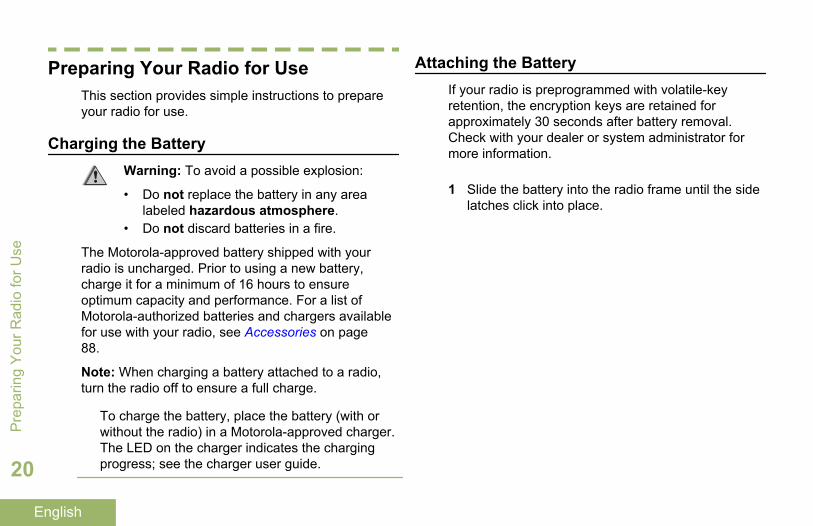
Preparing Your Radio for UseThis section provides simple instructions to prepareyour radio for use.
Charging the BatteryWarning: To avoid a possible explosion:
• Do not replace the battery in any arealabeled hazardous atmosphere.
• Do not discard batteries in a fire.
The Motorola-approved battery shipped with yourradio is uncharged. Prior to using a new battery,charge it for a minimum of 16 hours to ensureoptimum capacity and performance. For a list ofMotorola-authorized batteries and chargers availablefor use with your radio, see Accessories on page88.
Note: When charging a battery attached to a radio,turn the radio off to ensure a full charge.
To charge the battery, place the battery (with orwithout the radio) in a Motorola-approved charger.The LED on the charger indicates the chargingprogress; see the charger user guide.
Attaching the BatteryIf your radio is preprogrammed with volatile-keyretention, the encryption keys are retained forapproximately 30 seconds after battery removal.Check with your dealer or system administrator formore information.
1 Slide the battery into the radio frame until the sidelatches click into place.
Pre
parin
g Y
our R
adio
for U
se
20
English

2 To remove the battery, squeeze the releaselatches at the bottom of the battery until thebattery releases from the radio and remove thebattery from the radio.
Note: When removing the battery, ensure that theradio is turned off.
A
Attaching the AntennaEnsure the radio is turned off before attaching theantenna.
Preparing Y
our Radio for U
se
21
English

1 Set the antenna in its receptacle.
2 Turn the antenna clockwise to attach to the radio.
3 To remove the antenna, turn the antennacounterclockwise.
Note: When removing the antenna, ensure thatthe radio is turned off.
Removing and Attaching the AccessoryConnector Cover
The accessory connector is located on the antennaside of the radio. It is used to connect accessories tothe radio.
Note: To prevent damage to the connector, shield itwith the connector cover when not in use.
1 To remove the accessory connector cover, rotatethe thumbscrew counterclockwise until itdisengages from the radio.
Note: If the thumbscrew is too tight, use an Allenwrench at to loosen it first.
Pre
parin
g Y
our R
adio
for U
se
22
English

A
B
C
2 Rotate and lift the connector cover to disengage itfrom the radio.
3 To attach the accessory connector cover, insertthe hooked end of the cover into the slot abovethe connector.
4 Press downward on the cover’s top to seat it in theslot.
5 Once in place, tighten by rotating the thumbscrew clockwise by hand.
Attaching the Belt Clip
1 Align the grooves of the belt clip with those of theradio and press upward until you hear a click toattach the belt clip.
2 Use a flat-bladed object to press the belt clip tabaway from the radio. Then, slide the clipdownward and away from the radio to remove theclip.
Preparing Y
our Radio for U
se
23
English

Turning On the Radio
1 Rotate the On/Off/Volume Control Knobclockwise until you hear a click.
• If the power-up test is successful, you seemomentary SELFTEST on the radio display,followed by the Home screen.
• If the power-up test is unsuccessful, you seeERROR XX/YY (XX/YY is an alphanumericcode).
Note: If the radio fails to power-up afterrepeating a few times, record the ERROR XX/YYcode and contact your dealer.
Pre
parin
g Y
our R
adio
for U
se
24
English

2 To turn off the radio, rotate the On/Off/VolumeControl Knob counterclockwise until you hear aclick.
Adjusting the VolumeEnsure the radio is power on and the main speaker ispointed towards you for increased loudness andintelligibility, especially in areas with loud backgroundnoises.
1 To increase the volume, rotate the On/Off/VolumeControl Knob clockwise.
A
2 To decrease the volume, rotate this knobcounterclockwise.
Preparing Y
our Radio for U
se
25
English

Identifying Radio Controls
Radio Parts and Controls
7
654
8
12
3 19
18
17
16
15
9
11
10
12
13
14
1 Antenna
2 Top (Orange) Button[1]
3 Accessory Connector
4 16–Position Select Knob[1]
5 On/Off/Volume Control Knob
Iden
tifyi
ng R
adio
Con
trols
26
English

6 3–Position A/B/C Switch[1]
7 Belt Clip
8 Battery Latch
9 LED
10 2–Position Concentric Switch[1]
11 Top Side (Select) Button[1]
12 Push-to-Talk (PTT) Button
13 Side Button 1[1]
14 Side Button 2[1]
15 Top Display
16 Bluetooth Pairing Location Indicator
17 Microphone
18 Main Speaker
19 Battery
Programmable FeaturesAny reference in this manual to a control that ispreprogrammed means that the control must beprogrammed by a dealer or qualified radio technicianusing the radio programming software, in order toassign a feature to that control.
The programmable buttons can be programmed asshortcuts to radio functions or preset channels/groupsdepending on the duration of a button press:
Press Pressing and releasing rapidly.
Long Press Pressing and holding for thepreprogrammed duration (between0.25 seconds and 3.75 seconds).
Hold down Keeping the button pressed.
Assignable Radio Functions
Bluetooth On/Off Allows you to turn on/off theBluetooth.
Bluetooth AudioReroute
Allows you to toggle the audioroute between radio speaker or
1 These radio controls/buttons are programmable.
Identifying Radio C
ontrols
27
English

Remote Speaker Microphoneand Bluetooth headset.
BluetoothHeadset PTT
Keys up the Bluetooth Headsetmicrophone.
Bluetooth ClearAll Pairing
Allows you to clear all pairinginformation for Bluetooth. Thisis accessed by a long press ofthe Bluetooth On/Off Button.
Bluetooth InquiryOn/Off
Enables Bluetooth Searchfeature.
BluetoothDiscoverableOn/Off
Enables Bluetooth visibility.This is accessed by a longpress of the Bluetooth InquiryOn/Off Button.
Call Response Allows you to answer a privatecall.
Dynamic Priority(ConventionalOnly)
Allows any channel in a ScanList (except for the Priority-Onechannel) to temporarily replacethe Priority-Two channel.
Emergency Depending on theprogramming, initiates or
cancels an emergency alarm orcall.
Internet ProtocolAddress
Display the Internet Protocol(IP) address, device name andstatus of the radio.
Man Down Clear Clears the alarm of Man Downmode which was triggeredwhen your radio achieves orpasses a tilt angle threshold ora combination of the anglethreshold and a motionsensitivity level.
Monitor(ConventionalOnly)
Monitors a selected channel forall radio traffic until function isdisabled.
Nuisance Delete Temporarily removes anunwanted channel, except forpriority channels or thedesignated transmit channelfrom the scan list.
One Touch 1– 4 Launches a specific featurewith one single button-press.You can setup as many as four
Iden
tifyi
ng R
adio
Con
trols
28
English

separately programmed buttonsfor four different features.
Private LineDefeat(ConventionalOnly)
Overrides any coded squelch(DPL or PL) that ispreprogrammed to a channel.
Rekey Request Notifies the dispatcher you wanta new encryption key.
Repeater AccessButton (RAB)(ConventionalOnly)
Allows user to manually send arepeater access codeword.
ReprogramRequest(Trunking Only)
Notifies the dispatcher you wanta new dynamic regroupingassignment.
Request-To-Talk(ConventionalOnly)
Notifies the dispatcher you wantto send a voice call.
Scan Toggles scan on or off.
Scan ListProgramming
Selects the scan list for editing(by long press on the Scanbutton).
SecureTransmissionSelect(Conventionaland Trunking)
Toggles the SecureTransmission On or Off whenthe Secure/Clear Strappingfields is set to Select for thecurrent channel and when theradio is model/option capable.
Site Display/Search (TrunkingOnly)
Displays the current site ID andRSSI value; performs sitesearch for Automatic MultipleSite Select (AMSS) orSmartZone operation.
Site Lock/Unlock(Trunking Only)
Locks onto a specific site.
Talkaround/Direct(ConventionalOnly)
Toggles between using arepeater and communicatingdirectly with another radio.
Basic Zone Bank Provides access from up to 6zones by toggling between 2banks of 3 zones, one group of3 (A, B and C) to a secondgroup of 3 zones (D, E and F).
Enhanced ZoneBank
Provides access from up to 75zones by toggling between 25
Identifying Radio C
ontrols
29
English

banks (A, B ... X or Y) of 3zones.
Assignable Settings or Utility Functions
Controls Lock Locks or unlocks theprogrammable buttons,switches or rotary knobs.
Light/Flip Press the button to toggle thedisplay backlight on or off;press and hold the button toreverse the content of the topdisplay.
TX Power Level Toggles transmit power levelbetween high and low.
VoiceAnnouncement
Audibly indicates the currentfeature mode, Zone orChannel the user has justassigned.
Voice Mute Toggles voice mute on or off.
Volume Set Tone Sets the volume set tone.
Accessing the Preprogrammed FunctionsYou can access various radio functions through thefollowing method.
A short or long press of the relevantprogrammable buttons.
Push-To-Talk (PTT) Button
A
The PTT button on the side of the radio serves twobasic purposes:
Iden
tifyi
ng R
adio
Con
trols
30
English

• While a call is in progress, the PTT button allowsthe radio to transmit to other radios in the call.
Press and hold down PTT button to talk. Releasethe PTT button to listen. The microphone isactivated when the PTT button is pressed.
• While a call is not in progress, the PTT button isused to make a new call. See Making a Radio Callon page 43 for more information.
Identifying Radio C
ontrols
31
English

Identifying Status Indicators
Status IconsSelected icons are also shown on the first row of the112 x 32 pixel top monochrome display screen ofyour radio. The following icons are for the frontdisplay screen unless indicated otherwise.
Receiving
Radio is receiving a call or data.
Transmitting
Radio is transmitting a call or data.
Battery
For IMPRES battery operation only – theicon shown indicates the chargeremaining in the battery.
For all battery operation – the icon blinkswhen the battery is low.
Received Signal Strength Indicator(RSSI)
The number of bars displayedrepresents the received signal strengthfor the current site, for trunking only. Themore stripes in the icon, the stronger thesignal.
Roaming
The radio has roamed to and is currentlyregistered to a foreign system.
Direct
On – Radio is currently configured fordirect radio-to-radio communication(during conventional operation only).
Off – Radio is connected with otherradios through a repeater.
Monitor (Carrier Squelch)
Selected channel is being monitored(during conventional operation only).
Iden
tifyi
ng S
tatu
s In
dica
tors
32
English
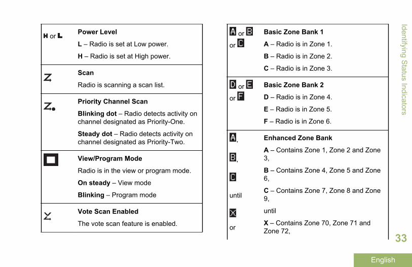
or Power Level
L – Radio is set at Low power.
H – Radio is set at High power.
Scan
Radio is scanning a scan list.
Priority Channel Scan
Blinking dot – Radio detects activity onchannel designated as Priority-One.
Steady dot – Radio detects activity onchannel designated as Priority-Two.
View/Program Mode
Radio is in the view or program mode.
On steady – View mode
Blinking – Program mode
Vote Scan Enabled
The vote scan feature is enabled.
or
or
Basic Zone Bank 1
A – Radio is in Zone 1.
B – Radio is in Zone 2.
C – Radio is in Zone 3.
or
or
Basic Zone Bank 2
D – Radio is in Zone 4.
E – Radio is in Zone 5.
F – Radio is in Zone 6.
,
,
until
or
Enhanced Zone Bank
A – Contains Zone 1, Zone 2 and Zone3,
B – Contains Zone 4, Zone 5 and Zone6,
C – Contains Zone 7, Zone 8 and Zone9,
until
X – Contains Zone 70, Zone 71 andZone 72,
Identifying Status Indicators
33
English

Y – Contains Zone 73, Zone 74 andZone 75.
Secure Operation
On Secure operation.
Off Clear operation.
Blinking Receiving an encryptedvoice call.
GPS Signal
On – Feature is enabled and signal isavailable.
Off – Feature is disabled.
Blinking – Feature is enabled, but nosignal is available.
Bluetooth On
Bluetooth is on and ready for Bluetoothconnection.
Bluetooth Connected
Bluetooth is currently connected to theexternal Bluetooth device.
LED IndicatorThe LED indicator shows the operational status ofyour radio.
A
Solid red Radio is transmitting.
Blinking red Radio is transmitting at lowbattery condition.
Double blinkingred
Radio is in Emergency Mode.
Iden
tifyi
ng S
tatu
s In
dica
tors
34
English

Rapidly blinkingred
Radio has failed the self testupon powering up orencountered a fatal error.
Solid yellow(ConventionalOnly)
Channel is busy.
Blinking yellow Radio is receiving a securedtransmission.
Solid green Radio is powering up, or is ona non-priority channel while inthe Scan List Programmingmode.
Blinking green Radio is receiving an individualor telephone call, or is on aPriority-Two channel while inthe Scan List Programmingmode.
Rapidly blinkinggreen
Radio is on a Priority-Onechannel while in the Scan ListProgramming mode.
Note: No LED indication when the radio receives aclear (non-secured) transmission in trunking Mode.LED indication can be preprogramed by qualifiedtechnician to be permanently disabled. Consult yourdealer for further details if you want to disable it.
Intelligent Lighting IndicatorsThis feature temporarily changes the backlight of the top display screen, and adds a color bar to the main displayscreen to help signal that a radio event has occurred.
Note: This feature must be preprogrammed by a qualified radio technician.
Identifying Status Indicators
35
English
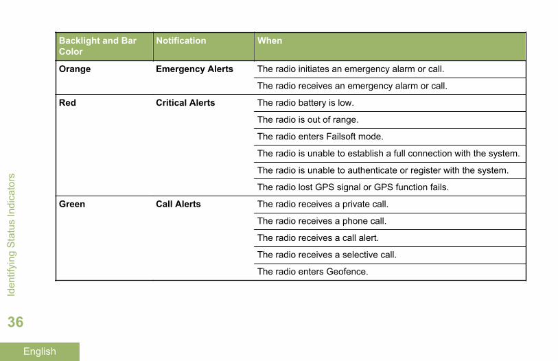
Backlight and BarColor
Notification When
Orange Emergency Alerts The radio initiates an emergency alarm or call.
The radio receives an emergency alarm or call.
Red Critical Alerts The radio battery is low.
The radio is out of range.
The radio enters Failsoft mode.
The radio is unable to establish a full connection with the system.
The radio is unable to authenticate or register with the system.
The radio lost GPS signal or GPS function fails.
Green Call Alerts The radio receives a private call.
The radio receives a phone call.
The radio receives a call alert.
The radio receives a selective call.
The radio enters Geofence.
Iden
tifyi
ng S
tatu
s In
dica
tors
36
English

Alert TonesYour radio uses alert tones to inform you of your radio’s condition. The following table lists these tones and whenthey occur.
You Hear Tone Name Heard
Short, Low-Pitched Tone
Radio Self Test Fail When radio fails its power-up self test.
Reject When an unauthorized request is made.
Time-Out Timer Warning Four seconds before time out.
No ACK Received When radio fails to receive an acknowledgment.
Individual Call WarningTone
When radio is in an individual call for greater than 6 secondswithout any activity.
Man Down Entry When radio initiates Man Down mode.
Long, Low-Pitched Tone
Time-Out Timer Timed Out After time out.
Talk Prohibit/PTT Inhibit (When PTT button is pressed) transmissions are not allowed.
Lack of Voice PTT Time out When the radio ends your call after it detected there are lack ofvoice for 5 seconds after the PTT is pressed and hold. Yourradio ends the call to enable your radio to receive calls fromother radio users.
Out of Range (When PTT button is pressed) the radio is out of range of thesystem.
Identifying Status Indicators
37
English

You Hear Tone Name Heard
Invalid Mode When radio is on an unpreprogrammed channel.
A Group ofLow-PitchedTones
Busy When system is busy.
Short, Medium-Pitched Tone
Valid Key-Press When a correct key is pressed.
Radio Self Test Pass When radio passes its power-up self test.
Clear Voice At beginning of a non-coded communication.
Priority Channel Received When activity on a priority channel is received.
Emergency Alarm /CallEntry
When entering the emergency state.
Central Echo When central controller has received a request from a radio.
Long, Medium-Pitched Tone
Volume Set When volume is changed on a quiet channel.
Emergency Exit When exiting the emergency state.
A Group ofMedium-Pitched Tones
Failsoft When the trunking system fails.
Automatic Call Back When voice channel is available from previous request.
Keyfail When encryption key has been lost.Iden
tifyi
ng S
tatu
s In
dica
tors
38
English

You Hear Tone Name Heard
Console Acknowledge When status, emergency alarm, or reprogram request ACK isreceived.
Received Individual Call When Call Alert or Private Call is received.
Site Trunking When a SmartZone trunking system fails.
Short, High-Pitched Tone(Chirp)
Low-Battery Chirp When battery is below preset threshold value.
Two High-Pitched Tones
GPS Fails When the GPS signal is lost or when GPS fails.
Ringing Phone Call Received When a land-to-mobile phone call is received.
Gurgle Dynamic Regrouping (When PTT button is pressed) a dynamic ID has been received.
Talk Permit (When PTT button is pressed) is verifying with the system foraccepting its transmissions.
Unique, Low-Pitched Chirp
New Message When a new message is received.
Unique, High-Pitched Chirp
Priority Status When a priority message is received.
Incremental-Pitched Tone
Bluetooth Paired When Bluetooth accessory is paired with the radio.
Identifying Status Indicators
39
English
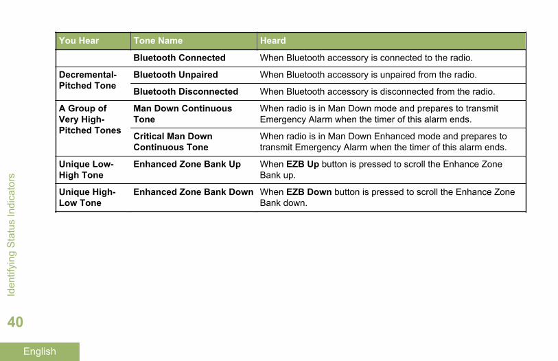
You Hear Tone Name Heard
Bluetooth Connected When Bluetooth accessory is connected to the radio.
Decremental-Pitched Tone
Bluetooth Unpaired When Bluetooth accessory is unpaired from the radio.
Bluetooth Disconnected When Bluetooth accessory is disconnected from the radio.
A Group ofVery High-Pitched Tones
Man Down ContinuousTone
When radio is in Man Down mode and prepares to transmitEmergency Alarm when the timer of this alarm ends.
Critical Man DownContinuous Tone
When radio is in Man Down Enhanced mode and prepares totransmit Emergency Alarm when the timer of this alarm ends.
Unique Low-High Tone
Enhanced Zone Bank Up When EZB Up button is pressed to scroll the Enhance ZoneBank up.
Unique High-Low Tone
Enhanced Zone Bank Down When EZB Down button is pressed to scroll the Enhance ZoneBank down.
Iden
tifyi
ng S
tatu
s In
dica
tors
40
English

General Radio Operation
Selecting a ZoneYour radio must be preprogrammed to allow you touse this feature.
A zone is a group of channels.
Select a zone via the preprogrammed Zone (3-Position A/B/C) switch:a) Move the preprogrammed Zone (3-Position
A/B/C) switch to the position of the requiredzone.If the zone number entered is unprogrammed,the display shows INVALID. Repeat this step.
b) Press the PTT button to transmit on thedisplayed zone channel.
Selecting a Radio ChannelA channel is a group of radio characteristics, such astransmit/ receive frequency pairs.
Select a channel via the preprogrammed 16–Position Select Knob to the desired channel.
a) Rotate the preprogrammed 16–PositionSelect Knob to the desired channel.
b) Press the PTT button to transmit on thedisplayed zone channel.
Receiving and Responding to a Radio CallOnce you have selected the required channel and/orzone, you can proceed to receive and respond tocalls.
The LED lights up solid red while the radio istransmitting. In conventional mode, the LED lights upsolid yellow when the radio is receiving atransmission. In trunking mode, there is no LEDindication when the radio receives a transmission.
If the radio is receiving a secure transmission, theLED blinks yellow.
Receiving and Responding to a Talkgroup Call
To receive a call from a group of users, your radiomust be configured as part of that talkgroup.
When you receive a talkgroup call (while on theHome screen) the radio triggers for your attention withone of the following scenarios depending on thesystem your radio is configured:
General R
adio Operation
41
English

• For ASTRO Conventional system, the LED lightsup solid yellow. The display shows the talkgroupalias or ID, and the caller alias or ID.
• For Trunking system, the display shows the calleralias or ID.
1 Hold the radio vertically 1 to 2 inches (2.5 to 5.0cm) from your mouth.
2 Press the PTT button to respond to the call.The LED lights up solid red.
3 Release the PTT button to listen.
See also Making a Talkgroup Call on page 43 fordetails on making a Talkgroup Call.
Receiving and Responding to a Private Call (TrunkingOnly)
A Private Call is a call from an individual radio toanother individual radio.
The one-to-one call between the two radios are notheard by the others in the current talkgroup. Thetransmitting radio automatically verifies that thereceiving radio is active on the system and candisplay the caller ID.
Note: With the inactivity timer enabled (optional),when there is no response from the receiving radio,the transmitting radio exits the call with Menu InactiveExit tone after the timer expires.
When you receive a Private Call, you hear two alerttones and the LED blinks green. The display showsCALL RCV, alternating with the caller alias (name) orID (number).
1 Press the Call Response button within 20seconds after the call indicators begin.
2 Press and hold the PTT button to talk. Release thePTT button to listen.
3 Press the Call Response button to hang up andreturn to the Home screen.
You cannot initiate a Private Call.
Receiving and Responding to a Telephone Call(Trunking Only)
This feature allows you to receive calls similar tostandard phone calls from a landline phone.
Gen
eral
Rad
io O
pera
tion
42
English

Note: With the inactivity timer enabled (optional), ifthere is no response to the call after the timer expires,your radio exits the call with Menu Inactive Exit tone.
When you receive a Telephone Call, you heartelephone-type ringing and the LED blinks green. Thedisplay shows PHN CALL and the call received iconblinks.
1 Press the Call Response button within 20seconds after the call indicators begin.
2 Press and hold the PTT button to talk. Release thePTT button to listen.
3 Press the Call Response button to hang up andreturn to the Home screen.
You cannot initiate a Telephone Call.
Making a Radio CallYou can select a zone, channel, subscriber ID, ortalkgroup by using:
• The preprogrammed Zone switch.• The 16-Position Select Channel Knob.
Making a Talkgroup Call
To make a call to a group of users, your radio mustbe configured as part of that talkgroup.
1 Turn the 16-Position Select Channel Knob toselect the channel with the desired talkgroup.
2 Hold the radio vertically 1 to 2 inches (2.5 to 5.0cm) from your mouth.
3 Press the PTT button to make the call.The radio shows different indicators based on thesystem the radio is configured.
• For ASTRO Conventional system, the LEDlights up solid red. The display shows thetalkgroup alias or ID.
• For Trunking system, the LED lights up solidred.
4 Speak clearly into the microphone.
5 Release the PTT button to listen.
General R
adio Operation
43
English
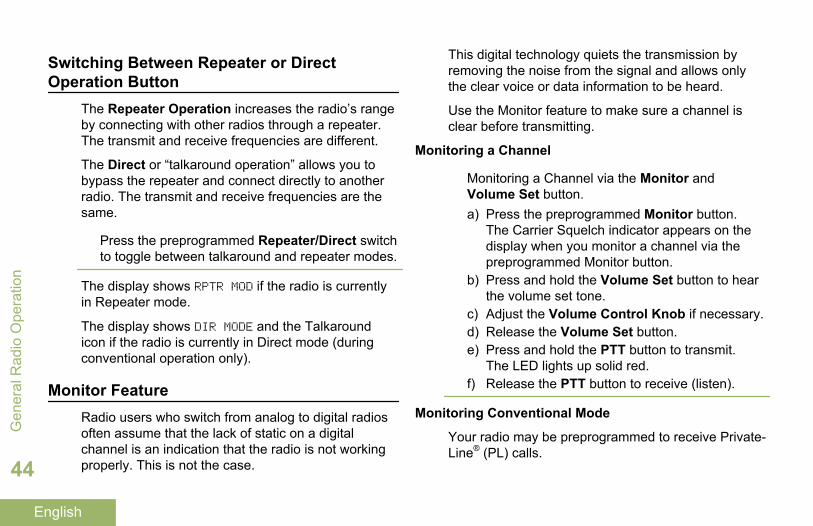
Switching Between Repeater or DirectOperation Button
The Repeater Operation increases the radio’s rangeby connecting with other radios through a repeater.The transmit and receive frequencies are different.
The Direct or “talkaround operation” allows you tobypass the repeater and connect directly to anotherradio. The transmit and receive frequencies are thesame.
Press the preprogrammed Repeater/Direct switchto toggle between talkaround and repeater modes.
The display shows RPTR MOD if the radio is currentlyin Repeater mode.
The display shows DIR MODE and the Talkaroundicon if the radio is currently in Direct mode (duringconventional operation only).
Monitor FeatureRadio users who switch from analog to digital radiosoften assume that the lack of static on a digitalchannel is an indication that the radio is not workingproperly. This is not the case.
This digital technology quiets the transmission byremoving the noise from the signal and allows onlythe clear voice or data information to be heard.
Use the Monitor feature to make sure a channel isclear before transmitting.
Monitoring a Channel
Monitoring a Channel via the Monitor andVolume Set button.a) Press the preprogrammed Monitor button.
The Carrier Squelch indicator appears on thedisplay when you monitor a channel via thepreprogrammed Monitor button.
b) Press and hold the Volume Set button to hearthe volume set tone.
c) Adjust the Volume Control Knob if necessary.d) Release the Volume Set button.e) Press and hold the PTT button to transmit.
The LED lights up solid red.f) Release the PTT button to receive (listen).
Monitoring Conventional Mode
Your radio may be preprogrammed to receive Private-Line® (PL) calls.
Gen
eral
Rad
io O
pera
tion
44
English

1 Momentarily press the Monitor button to listen foractivity.The Carrier Squelch indicator appears on thedisplay.
2 Press and hold the Monitor button to setcontinuous monitor operation.The duration of the button press is programmable.
3 Press the Monitor button again, or the PTTbutton, to return to the original squelch setting.If you try to transmit on a receive-only channel,you hear an invalid tone until you release the PTTbutton.
General R
adio Operation
45
English

Advanced Features
Advanced Call FeaturesSelective Call (ASTRO Conventional Only)
This feature allows you to receive a call from aspecific individual with privacy and without theannoyance of having to listen to conversations thatare of no interest to you.
Receiving a Selective Call
When you receive a Selective Call, you hear two alerttones and the LED lights up solid yellow. Thebacklight of the screen turns green momentarily andthe display briefly shows CALL RCV.
The speaker unmutes.
1 Hold the radio vertically 1 to 2 inches (2.5 to 5.0cm) from your mouth.
2 Press and hold the PTT button to talk. Release thePTT button to listen.
You cannot initiate a Selective Call.
Responding to the Dynamic Regrouping Feature(Trunking Only)
This feature allows the dispatcher to temporarilyreassign selected radios to a particular channelwhere they can communicate with each other. Thisfeature is typically used during special operations andis enabled by a qualified radio technician.
You will not notice whether your radio has this featureenabled until a dynamic regrouping command is sentby the dispatcher.
Note: If you try to access a zone or channel that hasbeen reserved by the dispatcher as a dynamicallyregrouped mode for other users, you hear an invalidtone.
When your radio is dynamically regrouped, itautomatically switches to the dynamically regroupedchannel. You hear a Gurgle tone and the displayshows the dynamically regrouped channel’s name.
Press the PTT button to talk. Release PTT buttonto listen.
When the dispatcher cancels dynamic regrouping, theradio automatically returns to the zone and channel
Adv
ance
d Fe
atur
es
46
English
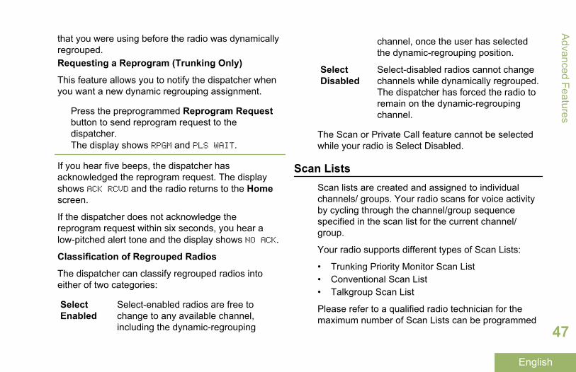
that you were using before the radio was dynamicallyregrouped.Requesting a Reprogram (Trunking Only)
This feature allows you to notify the dispatcher whenyou want a new dynamic regrouping assignment.
Press the preprogrammed Reprogram Requestbutton to send reprogram request to thedispatcher.The display shows RPGM and PLS WAIT.
If you hear five beeps, the dispatcher hasacknowledged the reprogram request. The displayshows ACK RCVD and the radio returns to the Homescreen.
If the dispatcher does not acknowledge thereprogram request within six seconds, you hear alow-pitched alert tone and the display shows NO ACK.
Classification of Regrouped Radios
The dispatcher can classify regrouped radios intoeither of two categories:
SelectEnabled
Select-enabled radios are free tochange to any available channel,including the dynamic-regrouping
channel, once the user has selectedthe dynamic-regrouping position.
SelectDisabled
Select-disabled radios cannot changechannels while dynamically regrouped.The dispatcher has forced the radio toremain on the dynamic-regroupingchannel.
The Scan or Private Call feature cannot be selectedwhile your radio is Select Disabled.
Scan ListsScan lists are created and assigned to individualchannels/ groups. Your radio scans for voice activityby cycling through the channel/group sequencespecified in the scan list for the current channel/group.
Your radio supports different types of Scan Lists:
• Trunking Priority Monitor Scan List• Conventional Scan List• Talkgroup Scan List
Please refer to a qualified radio technician for themaximum number of Scan Lists can be programmed
Advanced Features
47
English
in your radio. These lists must be preprogrammed bya qualified radio technician.
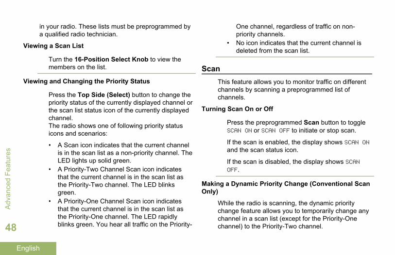
Viewing a Scan List
Turn the 16-Position Select Knob to view themembers on the list.
Viewing and Changing the Priority Status
Press the Top Side (Select) button to change thepriority status of the currently displayed channel orthe scan list status icon of the currently displayedchannel.The radio shows one of following priority statusicons and scenarios:
• A Scan icon indicates that the current channelis in the scan list as a non-priority channel. TheLED lights up solid green.
• A Priority-Two Channel Scan icon indicatesthat the current channel is in the scan list asthe Priority-Two channel. The LED blinksgreen.
• A Priority-One Channel Scan icon indicatesthat the current channel is in the scan list asthe Priority-One channel. The LED rapidlyblinks green. You hear all traffic on the Priority-
One channel, regardless of traffic on non-priority channels.
• No icon indicates that the current channel isdeleted from the scan list.
ScanThis feature allows you to monitor traffic on differentchannels by scanning a preprogrammed list ofchannels.
Turning Scan On or Off
Press the preprogrammed Scan button to toggleSCAN ON or SCAN OFF to initiate or stop scan.
If the scan is enabled, the display shows SCAN ONand the scan status icon.
If the scan is disabled, the display shows SCANOFF.
Making a Dynamic Priority Change (Conventional ScanOnly)
While the radio is scanning, the dynamic prioritychange feature allows you to temporarily change anychannel in a scan list (except for the Priority-Onechannel) to the Priority-Two channel.
Adv
ance
d Fe
atur
es
48
English

This change remains in effect until scan is turned off.Scan then reverts to the preprogrammed (original)setting.
Making a Dynamic Priority Change via thepreprogrammed Dynamic Priority button:a) When the radio locks onto the channel
designated as the new Priority-Two channel,press the preprogrammed Dynamic Prioritybutton.The radio continues scanning the remainingchannels in the list.
Deleting a Nuisance Channel
If a channel continually generates unwanted calls ornoise (termed a “nuisance” channel), you cantemporarily remove the unwanted channel from thescan list.
This capability does not apply to priority channels orthe designated transmit channel.
Note: Deleting a nuisance channel is only possiblethrough the preprogrammed Nuisance ChannelDelete button.
When the radio is locked onto the channel to bedeleted, press the preprogrammed NuisanceDelete button.
The radio continues scanning the remaining channelsin the list.
Restoring a Nuisance Channel
To restore the deleted nuisance channel, performone of the following actions:
• Turn scan off, and then on.• Change channels.• Turn off the radio, and then turn it back on.
Nuisance mode delete can be disabled by thesystem administrator.
Call Alert PagingThis feature allows your radio to work like a pager.
The radio which you missed its call can send a CallAlert page to your radio. The sender also able toknow that your radio is active.
Note: This feature must be preprogrammed by aqualified radio technician.
Advanced Features
49
English

Receiving a Call Alert Page
When you receive a Call Alert page, you hear fourrepeating alert tones and the LED blinks green. Thecall received icons blinks and the display shows PAGERCV.
Press any button to clear the Call Alert page.
You cannot send a Call Alert page.
Emergency OperationThe Emergency feature is used to indicate a criticalsituation.
If the Top (Orange) button is preprogrammed to sendan emergency signal, this signal overrides any othercommunication over the selected channel.
Your radio supports the following Emergency modes:
• Emergency Alarm• Emergency Call (Trunking Only)• Emergency Alarm with Emergency Call• Silent Emergency Alarm
Check with your dealer or system administrator formore information on the programming of this feature.
Only one of the Emergency modes above can beassigned to the preprogrammed Emergency button.
Note: To exit emergency at any time, press and holdthe preprogrammed Emergency button for about asecond.
The radio operates in the normal dispatch mannerwhile in Emergency Call, except if enabled, it returnsto one of the following:
Tactical/Non-Revert
The radio sends emergencyalarm and/or make emergencycall on the current selectedchannel.
Non-Tactical/Revert forConventionalsystem
The radio reverts to thepreprogrammed emergencychannel to send alarm and/ormake emergency call.
Non-Tactical/Revert forTrunking system
The radio reverts to thepreprogrammed emergencytalkgroup to send alarm and/ormake emergency call.
Man Down is an alternate way to activate theEmergency feature on the condition the Emergencymust be set up for this feature to operate.
Adv
ance
d Fe
atur
es
50
English

See Man Down on page 56 for details.
Sending an Emergency Alarm
This feature allows you to send a data transmission,which identifies the radio sending the emergency, tothe dispatcher.
Note: Emergency button press timer by default is setto 1 second. This timer is programmable from 0 – 6seconds by a qualified technician.
Press the preprogrammed Emergency button.
One of the following scenarios occurs:
• The display shows EMERGENCY and the currentzone or channel. You hear a short medium-pitched tone and the LED blinks redmomentarily.
• You hear the radio sounds a short low-pitchedtone to indicate that the selected channel doesnot support emergency and rejects to launchemergency mode.
When you receive the dispatcher’s acknowledgment,the display shows ACK RCVD. You hear four tones, thealarm ends, and the radio exits the Emergency Alarmmode.
If no acknowledgement is received, the display showsNO ACK. The alarm ends and the radio exits theEmergency Alarm mode.
Sending an Emergency Call (Trunking Only)
This feature gives your radio priority access to atalkgroup.
1 Press the preprogrammed Emergency button.One of the following scenarios will occur:
• The display shows EMERGNCY and the currentzone or channel. You hear a short medium-pitched tone and the LED blinks redmomentarily.
• You hear the radio sounds a short low-pitchedtone to indicate the selected channel does notsupport emergency and rejects to launchemergency mode.
2 Hold the radio vertically 1 to 2 inches (2.5 to 5.0cm) from your mouth.
3 Press and hold the PTT button. Speak clearly intothe microphone.
Advanced Features
51
English

4 Release the PTT button to end the transmissionand wait for a response from the dispatcher.
5 To exit Emergency Call, press and hold thepreprogrammed Emergency button for about asecond.
Sending an Emergency Alarm with Emergency Call
This feature gives your radio priority access on achannel for conventional system, and to a talkgroupfor trunking system.
1 Press the preprogrammed Emergency button.
If successful, the display shows EMERGNCY on thecurrent zone and channel. You hear a short,medium-pitched tone and the LED blinks redmomentarily.
The radio exits Emergency Alarm and enters theEmergency Call state when one of the followingscenarios occur:
• You receive the dispatcher’s acknowledgment.The display shows ACK RCVD.
• You receive no acknowledgement. The displayshows NO ACK.
• You press the PTT button while in theEmergency Alarm mode.
If unsuccessful, you hear the radio sounds a shortlow-pitched tone to indicate the selected channeldoes not support emergency and rejects to launchemergency mode.
2 Hold the radio vertically 1 to 2 inches (2.5 to 5.0cm) from your mouth.
3 Press and hold the PTT button. Speak clearly intothe microphone.
4 Release the PTT button to end the transmissionand wait for a response from the dispatcher.
5 To exit Emergency Call, press and hold thepreprogrammed Emergency button for about asecond.Turning the radio off also cancels the emergencystate.
Sending a Silent Emergency Alarm
This feature allows you to send an Emergency Alarmto the system without triggering any audio or visualindicators.
Adv
ance
d Fe
atur
es
52
English

1 Press the preprogrammed Emergency button.The display shows no changes, the LED does notlight up, and you hear no tones. The silentemergency state continues until you perform thenext step.
2 Perform one of the following actions:
• You press and hold the preprogrammedEmergency button for about a second to exitthe Silent Emergency Alarm mode.
• Press and release the PTT button to exit theSilent Emergency Alarm mode and enterregular dispatch or Emergency Call mode.
Change of Channels during Emergency
For ALL Emergency transmissions, when changingchannels:
• If the new channel is also preprogrammed forEmergency, you can change channels while inEmergency operation. The emergency alarm orcall continues on the new channel.
• If the new channel is NOT preprogrammed forEmergency, the display shows NO EMERG, and youhear an invalid tone until you exit the Emergency
state or change to a channel preprogrammed forEmergency.
Emergency Keep-Alive Feature
This feature, when enabled, prevents the radio frombeing turned off via the On/Off Control Knob whenthe radio is in the Emergency state.
Note: The radio only exits the Emergency state usingone of the ways mentioned in the previous sections.
See Sending an Emergency Alarm on page 51, Sending an Emergency Call (Trunking Only) on page51, Sending an Emergency Alarm with EmergencyCall on page 52, or Sending a Silent EmergencyAlarm on page 52.
Fireground (Conventional Only)The portable Fireground Communications System isdesigned for deployment at an incident scene. Itconsists of five central components:
• Your APX portable radios• Incident Management Software• Command Terminal• Radio Frequency (RF) Modem• DVRS (Optional)
Advanced Features
53
English

These components provide on-scene and inbuildingradio coverage, and enhanced personnelaccountability and monitoring.
The radio helps to indicate your presence on thescene if it is in the range of the Incident Commandercommand terminal.
Each Fireground Communication System radioautomatically reports your radio ID on the commandermobile command terminal. Your name, riding positionand sector are all can be configured to be seen at theCommander’s command terminal.
If you have a critical situation, you can press theEmergency button which activates an alarm on theIncident Management Software at the commandterminal.
The Fireground signals transmission is alwaysexchanging data between your radio and the RFModem and command terminal. The status of yourradio includes:
• Powering up or down the radio• Automatic response to Polling• Response to Evacuation commands• Pressing the PTT button to make voice
transmission
• Sending an Emergency Alarm and Call
Entering Fireground Zone Channel
1 Upon powering up, perform one of the followingactions:
• If the Fireground Zone Channel is set asdefault, you hear gurgle tone and the homescreen. You are in Fireground zone channel.
• If the Fireground Zone Channel is set asdefault, but you hear a short, low-pitched tone,the display shows REG FAIL to indicate that thecommand terminal does not respond toFireground Zone Channel. Get a qualifiedtechnician for assistance.
• If your home channel is not Fireground ZoneChannel, toggle or change the radio zonechannel to Fireground Zone Channel.
2 Listen for a transmission. Adjust the VolumeControl Knob if necessary.
3 Perform one of the following actions:
• Press and hold the preprogrammed VolumeSet button to hear the volume set tone. Adjust
Adv
ance
d Fe
atur
es
54
English

the Volume Control Knob if necessary.Release the Volume Set button.
• At the desired Fireground zone and channel,press the preprogrammed Monitor button andlisten for activity. Adjust the Volume ControlKnob if necessary.
• If your radio is working in Fireground ZoneChannel, proceed to next step.
4 Press and hold the PTT button to transmit. TheLED lights up solid red while transmitting. Talk intothe microphone clearly if needed.
5 Release the PTT button to receive.You hear a Transmit End Tone.
Responding to Evacuation Indicator
When Incident Commander triggers Evacuationsignal from his command terminal, the RF Modemupdates everyone in the Fireground CommunicationSystem with the order to evacuate the incident site.
Your radio sounds the Evacuation Tone at the profilemaximum alert tone volume level. The display showsEVACUATE.
Perform one of the following actions:
• Move the Volume Control Knob to adjust thevolume of the Evacuation Tone from fullvolume.
• Perform any action on the radio other thanvolume adjustments to cancel the evacuationindications and update the command terminal.
• If preprogrammed with ManualAcknowledgement of Evacuation Command,pressing the PTT button shall cancel theindications and acknowledge the commandterminal.
Tactical Public Safety(TPS) (ConventionalOnly)
TPS enabled the user of a group to identify atransmission starts and ends clearly by displaying thecaller name or ID on the radio display.
Using TPS Normal Transmission
At TPS Zone Channel, perform one of thefollowing actions:
• Press PTT button to transmit. Talk clearly intothe microphone. Release PTT button to listen.
Advanced Features
55
English

• Receive and listen to call, the radio displaysthe caller’s name or ID.
Using TPS Emergency Transmission
The following are two important alert tones designedfor this feature.
EmergencyBeacon
During Emergency if the TPS radiouser pushes the Emergency button,the radio sounds a Beacon at themaximum volume of the radio atradio’s internal speaker and it is notadjustable. This beacon goes tosilent when user presses the PTTbutton for voice transmission.
EmergencyCall De-KeySidetone
The radio sounds an alert tone toremind radio user that theEmergency Mode is still active afteruser releases the PTT button for anEmergency call transmission. Thevolume of loudness depends on themaximum tone at your radio profile.
1 Press the Emergency button to enter EmergencyMode.You hear Emergency Beacon.
2 Press PTT button to make Emergency Call.
3 Release to listen.You hear Emergency Call De-Key Sidetone. Aftera short pause, you hear Emergency Beacon.
4 Long press Emergency button to exit Emergencymode and cancel Emergency Beacon.
Man DownMan Down condition is determined based upon theradio tilt angle or a combination of radio tilt angle andthe lack of radio motion.
Man Down feature is an alternate way to activate theEmergency feature if Emergency has beenprogrammed in your radio.
Note: This feature could be preprogrammed for allchannels that support Emergency feature or could bepreprogrammed specifically to a zone and channelwhich has Emergency feature. Consult your agent orqualified technician for more details.
Your radio automatically activates Emergency Alarmor Call when the radio achieves or passes a tilt anglethreshold or a combination of the angle threshold and
Adv
ance
d Fe
atur
es
56
English

radio motion below the motion sensitivity level,depending upon how the radio is programmed. Theradio must stay in this condition for a preprogrammedamount of time before the Emergency Alarm or Call isactivated.
Note: It is recommended that an Emergency button ispreprogrammed in order to allow the user to exit theemergency condition.
The Man Down feature provides a Clear function tothe user. After a Man Down condition has beendetected, the user can press a preprogrammed Clearbutton or preprogrammed Menu Select button tocancel the Man Down condition. The radio remains inthe Man Down state without triggering an emergencycondition until the radio is moved out of the ManDown state, at which point Man Down functionalityresumes.
The Man Down feature has three phases:
1 The radio senses the Man Down condition andPre-Alert Timer is initiated.
2 Man Down condition continues for the timeduration defined in the Pre-Alert Timer field. At theend of this time, the radio alerts the user on theMan Down status with an audible alert tone and
MAN-DOWN text on the screen. The Post-Alert Timeralso initiates at this point.
3 Man Down condition continues for the timeduration defined in the Post-Alert Timer field. Oncethe timer expires, the Emergency alarm istransmitted. The Man Down Clear function is usedin this phase to cancel the Man Down condition.
The following scenarios affect the timers:
• Pressing the PTT button suspends the Man Downtimers; releasing the PTT button re-initiates thePre-Alert Timer.
• Pressing other buttons on the radio does notimpact these timers.
• Repositioning the radio exits the Man Downfeature, which stops and resets the timers.
• Pressing a preprogrammed Clear button orpressing a Menu Select button preprogrammedfor Clear stops and resets the timers. The timersdo not restart until the radio is repositioned.
Note: Emergency must be set up for this feature tooperate. For details on operating the Emergencyalerts, please see Emergency Operation on page 50.
Advanced Features
57
English
If the radio is preprogrammed to horizontal only, itmust be worn in a vertical position otherwise the ManDown alert may be inadvertently triggered.
When the radio is programmed with Man Downfeature, special care is required when charging theradio with a wall mounted charger. See Proper Waysto Handle the Radio on page 85 for details.
Pre-Alert Timer
This timer sets the amount of time that a Man Downcondition must be present before the radio-user iswarned of the Man Down condition.
When the radio detects that it has returned to thevertical position or when the radio detects motion, thePre-Alert timer stops and is reset.
The Pre-Alert timer reinitiates when the radio detectsit is in the horizontal position or motionless again.
Post-Alert Timer
This timer sets the amount of time the radio needs toremain in the Man Down condition before theEmergency alarm is transmitted. When the Post-AlertTimer is initiated, the radio alerts the user with anaudible tone and displays the “MAN-DOWN” text.
See Exiting Man Down Feature on page 59 to exitMan Down feature.
Radio Alerts When Man Down Feature is Triggered
The Man Down alert tone volume is directly related tothe radio’s volume. Ensure that the radio’s volume isloud enough so that the user does not miss the Post-Alert tone.
Note: If the radio is programmed with SilentEmergency, the radio inhibits the alert tone and visualalert associated with the emergency feature.
If the radio is programmed in Surveillance Mode, theradio inhibits all tones and lights on the radioincluding the Man Down tones.
Triggering Emergency
When the user does not clear the Man Downcondition and the Post-Alert Timer comes to an end,Emergency Alarm or call is triggered. The radio sendsemergency message to units within the sameTalkgroup. The radio also sends ID number and GPScoordinates to dispatcher if these features areenabled. User can exit Emergency following theEmergency procedure. See Emergency Operation onpage 50 for details.
Adv
ance
d Fe
atur
es
58
English

Note: At this point the Man Down features iscomplete. Use normal Emergency procedures tocancel Emergency transmissions.
Radio Alerts When Man Down Enhanced is Triggered
Note: This feature is to be preprogrammedspecifically to a zone and channel which supportsEmergency feature.
The volume and repetition duration of Man DownEnhanced alert tone could be customized andpreprogrammed to suite the required situation.
Consult your agent or qualified technician for moredetails.
When the radio initiates Man Down Enhanced, youhear the Critical Man Down Continuous alert tonefrom the radio speaker. The volume of this tone is setto the louder of the preprogrammed minimum level orthe current radio speaker level. This acts as a beaconto find the radio.
Note: If the radio is programmed with SilentEmergency, the radio inhibits the alert tone and visualalert associated with the emergency feature.
If the radio is programmed in Surveillance Mode, thealert tone can be heard from the radio speaker.
Once the alert tone is active, changing to anotherchannel with different setup triggers a differentresponse from the radio as described next.
• The alert tone is inhibited when you change to achannel without Emergency feature.
• The alert tone is inhibited when you change to achannel with Emergency but no Man Downfeature.
• The current alert tone is inhibited and is replacedwith a different alert tone when you change to achannel with Emergency and different Man Downconfiguration.
• The alert tone continues when you change to achannel with Emergency and similar Man Downconfiguration.
Exiting Man Down Feature
If you are not in a real Man Down situation, youshould exit the Man Down feature and preventemergency from going off with the followingoperation.
Perform one of the following actions:
• Repositioning the radio or shaking the radio(when motion sensitivity is enabled).
Advanced Features
59
English

• Press the preprogrammed Man Down Clearbutton to exit.
Re-Initiating Man Down
After exiting the Emergency Operation when the radiois still in Man Down condition (tilted achievingthreshold angle or motionless), user must first exitMan Down condition to then reinitiate the Man Downfeature.
Return the radio to the vertical position or shakethe radio (when motion sensitivity is enabled).
Testing the Man Down Feature
Enable the Emergency feature with Silent Alarmdisabled, but not in Surveillance Mode before runningthis test on the radio.
1 Turn the radio on and place in the vertical position,for at least 5 seconds.
2 Lay the radio down in the horizontal position.
3 Wait for alert tone.
One of the following scenarios will occur:
• The radio alerts with audible tone and displaysMAN-DOWN.
• If no tone is heard, make sure that the Man Downfeature is enabled on your radio. If Man Downfeature was not enabled, please enable it andrepeat 1 to 3.
• If the Man Down feature is enabled and no tone isheard, send the radio to a qualified technician.
Secure OperationsSecure radio operation provides the highestcommercially available level of voice security on bothtrunked and conventional channels.
Unlike other forms of security, Motorola digitalencryption provides signaling that makes it virtuallyimpossible for others to decode any part of anencrypted message.
Selecting Secure Transmissions
Turn the preprogrammed Secure/Clear switch tothe secure position.
Note: If the selected channel is preprogrammedfor clear-only operation, when you press the PTT
Adv
ance
d Fe
atur
es
60
English

button, you hear an invalid mode tone and thedisplay shows CLR TX.
The radio will not transmit until you set theSecure/Clear switch to the clear position.
Selecting Clear Transmissions
Turn the preprogrammed Secure/Clear switch tothe clear position.
Note: If the selected channel is preprogrammedfor secure-only operation, when you press the PTTbutton, you hear an invalid mode tone and thedisplay shows SEC TX.
The radio will not transmit until you set theSecure/ Clear switch to the secure position.
The radio can be configured to ignore the clearvoice or insecured transmission when the radio isin secured transmission. Check with your agent fordetails.
Managing EncryptionLoading an Encryption Key
Note: Refer to the key-variable loader (KVL) manualfor equipment connections and setup.
1 Attach the KVL to your radio.The display shows KEYLOAD, and all other radiofunctions, except for power down, backlight, andvolume, are locked out.
2 Select the required keys and press the MenuSelect button directly below LOAD on the KVL.This loads the encryption keys into your radio.
When the key has been loaded successfully, one ofthe following scenarios occurs:
• You hear a short tone for single-key radios.• You hear an alternating tone for multikey radios.
Multikey Feature
This feature allows the radio to be equipped withdifferent encryption keys and supports the DES-OFBalgorithm.
There are two types:
ConventionalMultikey
The encryption keys can be tied(strapped), on a one-per-channelbasis, through CustomerProgramming Software. In addition,you can have operator-selectable
Advanced Features
61
English
keys, operator-selectable keysets,and operator-selectable keyerasure. If talkgroups are enabledin conventional, then the encryptionkeys are strapped to the talkgroups.
TrunkedMultikey
If you use your radio for bothconventional and trunkedapplications, you have to strap yourencryption keys for trunking on aper-talkgroup or announcement-group basis. In addition, you maystrap a different key to otherfeatures, such as dynamicregrouping, failsoft, or emergencytalkgroup. You can have operator-selectable key erasure.
Erasing the Selected Encryption Keys
This feature allows you to erase all or selectedencryption keys.
Erasing the single key in radios with the single-keyoption and erasing all keys in radios with themultikey option via the preprogrammed Top Side(Select) button and Top (Orange) button:a) Press and hold the Top Side (Select) button.
b) While holding Top Side (Select) button down,press the Top (Orange) button.The display shows PLS WAIT. When all theencryption keys have been erased, the displayshows ALL ERASED.
Note: Do not press the Top (Orange) buttonbefore pressing the Top Side (Select) button,unless you are in an emergency situation asthis sends an emergency alarm.
Requesting an Over-the-Air Rekey (ASTROConventional Only)
Ensure that the Unique Shadow Key (USK) is loadedinto the radio with the key-variable loader (KVL)before the rekey request can be sent. Refer to yourlocal key management supervisor for moreinformation.
This feature, also known as OTAR, allows thedispatcher to reprogram the encryption keys in theradio remotely. The dispatcher performs the rekeyoperation upon receiving a rekey request from theuser.
Press and hold the preprogrammed RekeyRequest button to send the rekey request.
Adv
ance
d Fe
atur
es
62
English

If the rekey operation fails, a bad-key tone soundsand the display shows RKY FAIL.
Note: The rekey operation failure indicates thatyour radio does not contain the Unique ShadowKey (USK).
MDC Over-the-Air Rekeying (OTAR) Page
This feature allows you to view or define MDC Over-the-Air Rekeying (OTAR) features. It is applied onlywhen operating in secure encrypted mode and onlyfor conventional communications. In additional toRekey Requests, OTAR transmissions includeDelayed Acknowledgements, and PowerupAcknowledgements.
Some of the options selected may also need to be setup at the Key Management Controller (KMC) site towork properly.
Note: This feature must be preprogrammed by aqualified radio technician. Check with your dealer orsystem administrator for more information.
Infinite UKEK Retention
This feature enables Unique Key Encryption Key(UKEK) to be permanently stored in the radio evenwhen all of the encryption keys is erased. Without this
UKEK key, the radio could not be over the airrekeyed.
Note: This feature must be preprogrammed by aqualified radio technician. Check with your dealer orsystem administrator for more information.
Hear Clear
Note: This feature must be preprogrammed by aqualified radio technician. Check with your dealer orsystem administrator for more information.
There are two components of Hear Clear.
Companding Reduces the channel noise, e.g.OTA transmission, that ispredominantly present in UHF2 and900 MHz channel with the followingfeatures.
Compressor Reduces thebackground noiseflow and the speechsignal at transmittingradio.
Expander Expands the speechwhile the noise flow
Advanced Features
63
English
remains the same atreceiving radio.
Random FMNoiseCanceller(FlutterFighter)
Reduces the unwanted effects ofrandom FM noise pulses caused bychannel fading under high Signal-to-Noise (S/N) conditions such as in amoving in a transportation. Thefading effects, heard as audio popsand clicks, are cancelled withoutaffecting the desired audio signal.
The Random FM Noise Cancelleroperates only in receive mode.
Global Positioning System (GPS)This feature uses information from the GlobalPositioning System (GPS) satellites orbiting the Earthto determine the approximate geographical location ofyour radio, expressed as latitude and longitude orMGRS format per request from customers. Theavailability and accuracy of this location information(and the amount of time that it takes to calculate it)varies depending on the environment in which youare using the GPS feature.
For example, GPS location fixes are very difficult toobtain indoors, in covered locations, between highbuildings, or in situations where you have notestablished a clear broad view of the sky.
Once GPS is enabled, the radio displays the GPSicon on the screen. The dispatcher can alwaysrequest the system to determine the real-time locationcoordinates of the radio.
GPS Operation
The GPS technology uses radio signals from earthorbiting satellites, to establish the locationcoordinates, maximizing your view of clearunobstructed sky is essential for optimumperformance.
Where adequate signals from multiple satellites arenot available (usually because you cannot establish aview of a wide area of the sky), the GPS feature ofyour radio will not work. Such situations include butare not limited to:
• Underground locations• Inside of buildings, trains, or other covered
vehicles• Under any other metal or concrete roof or
structure
Adv
ance
d Fe
atur
es
64
English

• Between tall buildings or under dense tree-cover• In temperature extremes outside the operating
limits of your radio
Even where location information can be calculated insuch situations, it may take longer to do so, and yourlocation estimate may not be as accurate. Therefore,in any emergency situation, always report yourlocation to your dispatcher.
Keep in mind that the accuracy of the locationinformation and the time it takes to obtain it variesdepending upon circumstances, particularly the abilityto receive signals from an adequate number ofsatellites.
Note: Even where adequate signals from multiplesatellites are available, your GPS feature onlyprovides an approximate location, usually within 20meters from your actual location, but sometimesfarther away.
The satellites used by the GPS feature are controlledby the U.S. government and are subject to changesimplemented in accordance with the Department ofDefense GPS user policy and the Federal RadioNavigation Plan. These changes may affect theperformance of the GPS feature on your radio.
GPS Performance Enhancement
Sometimes, the GPS feature may be unable tocomplete a location calculation successfully. You thensee a message indicating that your radio cannotconnect to enough visible satellites.
To maximize the ability of your radio to determine afix, take note of the following guidelines:
• For your initial fix, hold the radio in the faceposition.
• Stay in the open. The GPS feature works bestwhere there is nothing between your radio and alarge amount of open sky.
Peer-Location on the Display (ASTRO Conventionalonly)
This feature is only available for radio-to-radio voicetransmissions, dispatch call and selective call inconventional ASTRO system. For radio-to-radiotransmission, in order to allow the radio to show peer-location, the voice should be directly sent from oneradio to another radio without passing through anyinfrastructure facility such as repeaters, phone orDVRS system. Both the transmitting radio andreceiving radio must be configured to enable them tosend and/or receive the GPS coordinates. You can
Advanced Features
65
English

check with your nearest qualified technician for moredetails.
Note: If the receiving radio is operating in a MixedMode channel, only if its voice transmission is viaconventional ASTRO system then it can receive thelocation coordinates of its peers.
This feature is also operable in a Scan Active channelor Scan Talkback channel.
Upon receiving a voice transmission with GPScoordinates enabled on the receiving radio, thedisplay shows the coordinates available in full or inshort coordinates. There are two different formatsavailable. Refer to the following list for the detailsshown in the Peer-Location quick text. Consult youragent to pick the best format to configure to yourradio.
Full locationcoordinates
• PTT ID (This is optional.)• Longitude and latitude• Relative distance or
direction.
Short locationcoordinates
• PTT ID (This is optional.)• Longitude and latitude
Note:
If the transmitting radio is stale at its location after aperiod of time, the receiving radio display showsID:<PTT ID> LKL: <Coordinates> <distance>. Ifthe radio is not configured to show PTT ID, you seeLAST KNWN LOC: <Coordinates> <distance>.
If the transmitting radio does not have GPS or thereceiving radio could not decode the GPS signal ofthe received signal, the receiving radio display showsID:<PTT ID> UNK LOC. The PTT ID seen here isoptional to be shown on the display per requirementof usage.
Trunking System ControlsUsing the Failsoft System
The failsoft system ensures continuous radiocommunications during a trunked system failure. If atrunking system fails completely, the radio goes intofailsoft operation and automatically switches to itsfailsoft channel.
During failsoft operation, your radio transmits andreceives in conventional operation on apredetermined frequency. You hear a medium-pitched tone and the display shows FAILSOFT.
Adv
ance
d Fe
atur
es
66
English

When the trunking system returns to normaloperation, your radio automatically leaves failsoftoperation and returns to trunked operation.
To continue, in Failsoft, to communicate with othertalkgroups, refer to the following procedure.
1 Rotate the Mode Knob to change to a differentrepeater frequency.
2 Press the PTT button to talk, and release thebutton to listen.
Out-of-Range Radio
When your radio goes out of the range of the system,it can no longer lock onto a control channel.
You hear a low-pitched tone and/or the display showsthe currently selected zone/channel combination andOUT RNG. Your radio remains in this out-of-rangecondition until it locks onto a control channel, it locksonto a failsoft channel, or it is turned off.
Site Trunking Feature
If the zone controller loses communication with anysite, that site reverts to site trunking.
The display shows the currently selected zone/channel combination and STE TRNK.
Note: When this occurs, you can communicate onlywith other radios within your trunking site.
Locking and Unlocking a Site
This feature allows your radio to lock onto a specificsite and not roam among wide-area talkgroup sites.This feature should be used with caution, since itinhibits roaming to another site in a wide-areasystem.
Use the preprogrammed Site Lock/Unlock buttonto toggle the lock state between locked andunlocked.
The radio saves the new site lock state and returns tothe Home screen.
Site Display and Search Button
The Site Display and Site Search button allows youto view the name of the current site or force yourradio to change to a new one.
Viewing the Current Site
Press the preprogrammed Site Displ/Srch button.
Advanced Features
67
English

The display shows momentary the name of thecurrent site and its corresponding received signalstrength indicator (RSSI).Changing the Current Site
Press and hold down the preprogrammed SiteDispl/Srch button.You hear a tone and the display showsmomentary SCANNING.
When the radio finds a new site, it returns to theHome screen.
Mission Critical Wireless - Bluetooth®-This feature allows your radio to extend itsfunctionality by connecting to external proprietaryMotorola accessories.
Note: It is recommended to use Motorola proprietaryMission Critical Wireless (MCW) devices with APXradios during Mission Critical operations as otherBluetooth® devices may or may not meet the missioncritical standard.
Your radio must be preprogrammed to allow you touse this feature.
The default setting for Bluetooth-enabled radio isBluetooth ON. See Turning the Bluetooth Off on page69 to turn the Bluetooth OFF.
Currently your radio supports the following Bluetoothdevices or profiles.
• Headset (HSP)• Dial Up Networking (DUN)• Personal Area Networking (PAN)• Serial Port (SPP)
Turning the Bluetooth On
Turning the Bluetooth on via the preprogrammedbutton:a) Press the preprogrammed button to turn on the
Bluetooth.You hear a short, medium-pitched tone. The
display shows momentary BT ON, and appears.
If Bluetooth fails to launch, the display showsBT ON FL.
Adv
ance
d Fe
atur
es
68
English

Turning the Bluetooth Off
Turning the Bluetooth off via the preprogrammedbutton:a) Press the preprogrammed button to turn off the
Bluetooth.You hear a short, medium-pitched tone. The
display shows momentary BT OFF and disappears.
Re-Pair Timer
There are two options for configuring the Bluetoothpairing type of the radio. The type defines theduration the radio and the accessory retain thepairing information.
Immediate (For MCW accessories only.) When theradio and/or device is turned off afterpairing, the keys are lost. Due to this,when your radio and your device areturned back on, they are unable to re-connect. The user must re-pair thedevices to re-establish a new set ofpairing keys. See Pairing with LowFrequency-Motorola Proximity Pairing
(LF-MPP) Feature on page 71 and Standard Pairing Feature on page 72.
Infinite (For all Bluetooth devices.) When theradio and/or device are turned off afterpairing, keys are not lost. When theradio and the device are turned backon, they can resume the Bluetoothconnection without user intervention.
Re-PairTimerOptions
Re-Pair Timer Scenarios
Immediate(For MCWAccessoriesonly)
• When the radio is powered off,pairing key is lost immediately,and accessory attempts to pairagain. If pairing is unsuccessfulwithin the Drop Timer value, theaccessory automatically powersoff.
• When the accessory is poweredoff, all keys are lost immediately,and the user must re-pair thedevices.
Advanced Features
69
English

Re-PairTimerOptions
Re-Pair Timer Scenarios
• When the device loses Bluetoothconnection, the device willattempt to re-establish BluetoothConnection within the DropTimer value.
Infinite (For allBluetoothdevices)
• When the radio is powered off,the accessory attempts to re-establish the BluetoothConnection for a period of timedepending upon the Drop Timervalue. If the device fails toreconnect within the period, theaccessory then powers off.
Bluetooth Drop Timer
The Bluetooth Drop Timer has two different settingsand functions, depending upon the selection of theRe-Pair Timer.
Re-Pair TimerOptions
Description
Immediate(For MCWAccessoriesonly)
0 – 15 minutes programmablebuffer time to re-establish theBluetooth Connection when theBluetooth signal is out of range.
If either device powers off, thepairing keys are immediatelycleared from both devices and thedevices must re-pair.
Infinite (For allBluetoothdevices)
This Timer only applies to theaccessory. The programmabletimer choices are: 0 – 15 minutes, 2hours, 4 hours or 8 hours.
Do note there are exceptions forOperation Critical Wireless (OCW)headset and PTT which arepreprogrammed to 8 hours.
This is a "stay alive" time that theaccessory will remain on withoutthe device reconnecting beforepowering off. The radio will remain
Adv
ance
d Fe
atur
es
70
English

Re-Pair TimerOptions
Description
on until the user powers the radiooff. The radio and accessory willremain paired indefinitely. Once thedevice re-connect, the timer isreset.
The radio could not control the Drop Timer ofPersonal Area Networking (PAN), Dial-Up Networking(DUN), Commercial Off- The-Shelf (COTS) and dataservices. It is depends on the specifications of theseexternal devices.
Check with your dealer or system administrator formore information about these timers.
To establish the Bluetooth Connection, see Pairingwith Low Frequency-Motorola Proximity Pairing (LF-MPP) Feature on page 71 or Standard PairingFeature on page 72 .
Pairing with Low Frequency-Motorola Proximity Pairing(LF-MPP) Feature
Ensure that Bluetooth feature of your radio is on andthe Bluetooth tones are enabled.
Bluetooth tones, Bluetooth menu and preprogrammedbuttons must be preprogrammed by a qualified radiotechnician. Check with your dealer or systemadministrator for more information.
The range of Bluetooth operation is 10 meters line-of-sight communication. This is an unobstructed pathbetween the location of the signal transmitter (yourradio) and the location of the receiver (your device oraccessory).
Obstacles that can cause an obstruction in the line-of-sight include trees, buildings, mountains, cars andetc.
It is not recommended that you leave your radiobehind and expect your accessory to work with a highdegree of reliability when they are separated.
At the fringe areas of reception, both voice and tonequality will start to sound "garbled" or "broken". Tocorrect this problem, simply position the accessoryand radio closer to each other (within the 10 meterdefined range) to re-establish clear audio reception.
Note: Once a COTS headset is paired to your radio, itis always connected. Therefore the battery life of theaccessory is aligned with the Talk Time powerconsumption, not the Standby Time consumption.
Advanced Features
71
English

Turn on the accessory. Then place it close to yourradio aligning the Bluetooth Pairing Location ( )on the radio to the Bluetooth Pairing Location (ablue dot) on the accessory.
If the pairing process is successful, you hear anincremental-pitched tone. The radio begins toconnect to the device.
If the pairing process fails, you hear a short, low-pitched tone. The display shows PAIRINGalternates with FAILED. Repeat this step.
The radio tries to establish connection with the deviceonce paired.
Note: If the connection fails within 6 seconds, youhear a decremental-pitched tone to indicate that thedevice is unpaired. The display shows <DeviceType> UNPAIRED. Repeat this step to re-initiate thepairing process.
If the connection is successful, you hear anincremental-pitched tone. The display shows <DeviceType> CONNCTED and the Bluetooth icon turns from
to .
If the radio has the pairing record of the device andthe connection fails, you hear a short, low-pitchedtone. The display shows <Device Type> CON FAIL.
Radio Indications of Lost Bluetooth Connection
The radio shows when the device has a Bluetoothconnection. Below is the scenario and radioindications when the connection is interrupted.
The starts blinking for up to 10 seconds. You heara decremental-pitched tone. The display shows<Device Type> alternating with CON LOST.
If the Bluetooth device successfully re-connectsbefore the Bluetooth Drop Timer expires, the displayshows momentary <Device Type> CONNCTED, and
shows persistently, or if the Bluetooth device fails
to re-connect within 10 seconds, the blinking is
replaced by a persistent .
Standard Pairing Feature
Note: Bluetooth tones, Bluetooth menu andpreprogrammed buttons must be preprogrammed by
Adv
ance
d Fe
atur
es
72
English

a qualified radio technician. Check with your dealer orsystem administrator for more information.
Once a COTS headset is paired to your radio, it isalways connected. Therefore the battery life of theaccessory is aligned with the Talk time powerconsumption, not the Standby time consumption.
The Bluetooth Standard Pairing feature enables yourBluetooth enabled radio to search for other Bluetoothenabled and discoverable device. Once the device isdiscovered, your radio automatically pairs with thedevice.
This feature also enables your Bluetooth enabledradio to be visible to another Bluetooth enableddevice and receive request to pair from other device.
Searching and Pairing the Bluetooth Device
Ensure the Bluetooth on your device is turned to Onand is set to Discoverable in order to enable yourradio to detect your device in Bluetooth.
Bluetooth Search in Bluetooth Standard Pairingmethod is used to scan for other Bluetooth devicesnearby. It is set to off by default.
The radio only search for HSP devices and MotorolaMCW & OCW accessories. Radio will filter out otherprofiles.
Press the preprogrammed Bluetooth InquiryOn/Off button, to enable the Bluetooth Searchfeature.One of the following scenarios occurs:
• If successful, the display shows SRCH ONfollowed by SRCH END when the radio is pairingwith a device found. The display shows<Device Name> PAIRED to indicate pairing iscomplete.
• The display shows SRCH END when the searchtimer expires without pairing with any device.Repeat this step.
One of the following scenarios occurs:
• The radio continues to connect to the device. If theconnecting process is successful, the radiosounds an incremental-pitched tone. The displayshows <Device Type>CONNCTED, and theBluetooth icon turns from b to a.
• If the device already has pairing records and theconnecting process fails, the radio sounds a short,
Advanced Features
73
English

low-pitched tone. The display shows <DeviceType> CON FAIL.
• If the connection fails within 6 seconds, you hear adecremental-pitched tone to indicate that thedevice is unpaired. The display shows <DeviceType> UNPAIRED.
Turning Bluetooth Visibility On
Turning Bluetooth visibility to on enables otherBluetooth devices to search for your radio. Thevisibility of the Bluetooth is set to off by default.
Turn Bluetooth visibility on via the preprogrammedbutton.a) Press and hold the preprogrammed Bluetooth
Inquiry On/ Off button for three seconds toenable the Bluetooth visibility feature.One of the following scenarios occurs:
• Keep holding the button although you heara short, medium-pitched tone with thedisplay shows momentary VISIBLE.[2] Thisindicates the visibility is turned onsuccessfully.
• If the visibility fails to turn on, the displayshows VISIBLTYFAILED.
• When the timer expires, the display showsVISI OFF.
Receiving Pairing Request from other Devices
Turn on your radio Bluetooth Visible mode.Your radio automatically accept the request andpair with any request received from other device.
Turning On the Bluetooth Audio (Routing the Audiofrom the Radio to the Headset)
Turning on the Bluetooth audio via thepreprogrammed button:a) Press the preprogrammed Bluetooth Audio
Reroute button to route the audio from theradio to the headset.A short, medium-pitched tone sounds. Thedisplay shows HDSET ON.
2 Releasing the preprogrammed button turns off the Visibility mode.
Adv
ance
d Fe
atur
es
74
English

Turning Off the Bluetooth Audio (Routing the Audiofrom the Headset to the Radio)
Turning off the Bluetooth audio via thepreprogrammed button:a) Press the preprogrammed Bluetooth Audio
Reroute button to route the audio from theheadset to the radio.A short, medium-pitched tone sounds. Thedisplay shows SPKR ON.
Adjusting the Volume of the Radio from BluetoothAudio Device
Ensure that the Bluetooth audio device is connectedto the radio.
Your radio can only control the volume of MCW andOCW Bluetooth enabled audio device. If the radio ispaired with other Bluetooth enabled audio device, itsvolume is independent from the APX radio. In thiscase, the volume is only adjustable on the device.
Adjust volume up/down on the Bluetooth audiodevice.The radio display shows VOL XX and sounds ashort, medium-pitched tone.
Clearing All Bluetooth Devices Information
Clearing all Bluetooth devices information via thepreprogrammed Bluetooth On/Off button:a) Long press the preprogrammed Bluetooth
On/Off button.
You hear a short, medium-pitched tone. Thedisplay shows PLS WAIT to indicate clearing isin progress.
If successful, the display shows ALL CLR.
If unsuccessful, you hear the radio sounds ashort, low-pitched tone.The display shows CLRFAIL.
Note: If Re-Pair Timer is set to infinite and you clearkeys on the radio, you must clear keys on allpreviously paired devices as well. (Please see youraccessories manual for further details.)
Programming Over Project 25 (POP 25)(ASTRO 25 and ASTRO Conventional)
This feature enables configuration data to beupgraded to your radio over-the-air. This featureretains full use of the radio during the configuration
Advanced Features
75
English

data transfer without interrupting communication. Theupgrade pauses to give priorities to voice call, andcontinues after the voice call ended.
Once a configuration upgrade is downloaded to yourradio, you can install new changes immediately ordelay changes to be installed on the radio when it isbeing powered up.
Note: This feature must be preprogrammed by aqualified radio technician. Check with your dealer orsystem administrator for more information.
Voice AnnouncementThis feature enables the radio to audibly indicate thecurrent feature mode, zone or channel the user hasjust assigned. This audio indicator can be customizedper customer requirements. This is typically usefulwhen the user is in a difficult condition to read thecontent shown on the display.
Each voice announcement is within a limit of threeseconds maximum. The sum duration of all differentvoice announcements in a radio shall be no morethan 1000 seconds.
Note: This feature must be preprogrammed by aqualified radio technician.
Check with your agent if Voice Announcement isavailable for the feature you need.
The two options of priority for the VoiceAnnouncement available are:
High Enables the voice of the feature to announceeven when the radio is receiving calls.
Low Disables the voice of the feature fromannouncing when the radio is receiving calls.
You hear a voice announcement when the featuresbelow are preprogrammed in the radio.
• The radio powers up. The radio announces thecurrent zone and channel it is transmitting.
• Press the preprogrammed voice announcementbutton (which specifically programmed to playbackthe current zone and channel). The radioannounces the current zone and channel it istransmitting.
Note: Pressing this preprogrammed playbackbutton will always enable the voice feature toannounce in High priority.
All the three programmable buttons at the side ofthe radio support this feature.
Adv
ance
d Fe
atur
es
76
English

• Change to a new zone. The radio announces thecurrent zone and channel it is transmitting.
• Change to a new channel remaining within thecurrent zone. The radio announces the currentchannel.
• Press either the preprogrammed button or switchof the radio to launch or terminate Scan,Talkaround/Direct or Transmit Inhibit. The radioannounces the corresponding feature activation.
Site Selectable Alerts (ASTRO 25)A Site Selectable Alert (SSA) is an Intelligent Lightingindicator together with audio alert sent to radios at asite or a few sites to notify the users when there is aspecial situation that they need to be aware of. Onlyauthorized radios are enabled to send SSA.
Upon the activation of a SSA, the receiving radiosdisplay the alert alias and generate the periodic alerttone.
Note: Alert alias, alert tone, and alert period can bepreprogrammed. Alert period is the duration for theradio to repeat the alert tone. An interval of 5 secondsmight impact the battery life of the radio. Check withyour dealer or system administrator for more details.
When mixing SSA with received voice audio, the SSAalert is reduced in volume to ensure that the voicemessage is still heard clearly. Therefore, it isimportant that the SSA audio files are created withclear loud audio to ensure they can still be heardclearly when played at reduced levels.
UtilitiesUsing the Flip Display
This feature allows you to flip the content of the topdisplay upside down. It is particularly useful when youwould like to read the top display while the radio isstill in the carry holder attached to your belt.
To flip the display, press and hold thepreprogrammed Light/Flip button
Selecting a Basic Zone Bank
The Basic Zone Select feature must to bepreprogrammed to the 3-position A-B-C switch,while the Basic Zone Bank feature must bepreprogrammed to any side button or Top (Orange)button before you can use this feature.
Advanced Features
77
English
This feature allows twice as many zones to beaccessed from a switch, doubling the amount ofswitch positions.
Use the preprogrammed Basic Zone Bank buttonto toggle the position between Bank 1 and Bank 2.The top display shows the status icons (A, B, C, D,E or F) or the zone name based on the bank andswitch position selected.
Note: See the Basic Zone Bank 1 and Basic ZoneBank 2 icons for more information on the statusicons.
Selecting an Enhanced Zone Bank
This feature is created in order to allow users tocommunicate in more zones. An Enhanced ZoneBank (EZB) consists of three zones. This also meanseach icon A, B, C, ... or Y consist of three zones. Youcan use the preprogrammed 3-position A-B-C switchto select the first, second or third zone in an EZB.
This feature allows user to navigate from up to 75zones in 25 EZBs.
Note: The Zone Select feature must to bepreprogrammed to the 3-position A-B-C switch,while the Enhanced Zone Bank feature must be
preprogrammed to any side button or Top (Orange)button before you can use this feature.
1 Press the preprogrammed EZB Up or EZB Downbutton to scroll the EZB up or down or press andhold the preprogrammed EZB Up or EZB Downbutton to fast scroll the EZB up or down.
2 Turn the 3-Position A/B/C Switch to select thefirst, second or third zone in the selected EZB.
Selecting the Power Level
Note: This feature must be preprogrammed by aqualified radio technician.
This feature enables you to reduce the transmitpower level for specific case that requires a lowerpower level. You can select the power level at whichyour radio transmits. The radio always turns on to thedefault setting. These reduced transmit power levelsettings do not affect the receiving performance ofyour radio, nor diminish the overall quality of theaudio and data functionality of the radio given thefollowing conditions.
Power level Low enables a shorter transmittingdistance and to conserve power. Power level Highenables a longer transmitting distance.
Adv
ance
d Fe
atur
es
78
English

Use the preprogrammed Transmit Power Levelswitch to toggle the power level between low andhigh power.
The display shows LOW PWR and the low power iconor the display shows HIGH PWR and the high powericon.
Controlling the Display Backlight
You can enable or disable the radio’s displaybacklight as needed, if poor light conditions make thedisplay or keypad difficult to read.
Note:
The backlight remains on for a preprogrammed timebefore it automatically turns off completely or returnsto the minimum backlight level.
Perform one of the following actions:
• To toggle the backlight on or off, press thepreprogrammed Light/Flip button.
• To turn the backlight on, press anyprogrammable radio controls or buttons.
Locking and Unlocking the Controls
You can lock the programmable buttons, switchesand rotary knobs of your radio to avoid inadvertententry. Check with your dealer or qualified technicianfor best selection to suit your usage.
1 Toggle the preprogrammed Keypad/Control Lockbutton or switch to on.
2 The display shows CTRL LCK.
3 To unlock the knobs and buttons, toggle again.
Turning Voice Mute On or Off
You can enable and disable voice transmission, ifneeded.
Turning Voice Mute on or off via thepreprogrammed Voice Mute button:a) To turn the feature off or on, press the
preprogrammed Voice Mute button.
The display shows momentary VMUT OFF, and youhear a short tone, indicating that the feature isdisabled or the display shows momentary VMUT ON,
Advanced Features
79
English

and you hear a short tone, indicating that the featureis enabled.
Using the Time-Out Timer
This feature turns off your radio’s transmitter. Youcannot transmit longer than the preset timer setting.
If you attempt to do so, the radio automatically stopsyour transmission, and you hear a talk-prohibit tone.
The timer is defaulted at 60 seconds, but it can bepreprogrammed from 3 to 120 seconds, in 15-secondintervals, or it can be disabled entirely for each radiomode, by a qualified radio technician.
Note: You hear a brief, low-pitched, warning tone fourseconds before the transmission times out.
1 Hold down the PTT button longer than thepreprogrammed time.You hear a short, low-pitched warning tone, thetransmission is cut-off, and the LED goes out untilyou release the PTT button.
2 Release the PTT button.The timer resets.
3 To re-transmit, press the PTT button.
The time-out timer restarts and the LED lights upsolid red.
Using Conventional Squelch Operation Features
This feature filters out unwanted calls with low signalstrength or channels that have a higher than normalbackground noise.Analog Options
Tone Private Line (PL), Digital Private-Line (DPL),and carrier squelch can be available(preprogrammed) per channel.
Mode Result
Carrier squelch (C) You hear all traffic on achannel.
PL or DPL The radio responds onlyto your messages.
Digital Options
One or more of the following options may bepreprogrammed in your radio. Check with your dealeror system administrator for more information.A
dvan
ced
Feat
ures
80
English

Option Result
Digital Carrier-OperatedSquelch (COS)
You hear any digitaltraffic.
Normal Squelch You hear any digitaltraffic having the correctnetwork access code.
Selective Switch You hear any digitaltraffic having the correctnetwork access code andcorrect talkgroup.
Using the PL Defeat Feature
This feature allows you to override any coded squelch(DPL or PL) that might be preprogrammed to achannel. The radio also unmutes to any digital activityon a digital channel.
Place the preprogrammed PL Defeat switch in thePL Defeat position.One of the following scenarios occurs:
• You hear any activity on the channel.• The radio is muted if no activity is present.
Note: When this feature is active, the CarrierSquelch status indicator is displayed.
Digital PTT ID Support
This feature allows you to see the radio ID (number)of the radio from whom you are currently receiving atransmission. This ID, consisting up to a maximum ofeight characters, can be viewed by both the receivingradio and the dispatcher.
Your radio’s ID number is also automatically sentevery time the PTT button is pressed. This is a per-channel feature. For digital voice transmissions, yourradio’s ID is sent continuously during the voicemessage.
Smart PTT Feature (Conventional Only)
Smart PTT is a per-personality, programmablefeature used in conventional radio systems to keepradio users from talking over other radioconversations.
When smart PTT is enabled in your radio, you cannottransmit on an active channel.
If you try to transmit on an active smart-PTT channel,you hear an alert tone, and the transmission is
Advanced Features
81
English

inhibited. The LED lights up solid yellow to indicatethat the channel is busy.
The following table shows the variations of smartPTT:
Mode Description
Transmit Inhibiton BusyChannel withCarrier
You cannot transmit if any trafficis detected on the channel.
Transmit Inhibiton BusyChannel withWrong SquelchCode
You cannot transmit on an activechannel with a squelch code or (ifsecure-equipped) encryption keyother than your own. If the PLcode is the same as yours, thetransmission is not prevented.
Quick-KeyOverride
This feature can work inconjunction with either of the twoabove variations. You canoverride the transmit-inhibit stateby quick-keying the radio. Inother words, two PTT buttonpresses within thepreprogrammed time limit.
Transmit Inhibit
This feature is available for APCO 25 trunking, Type IItrunking and Conventional operations for all APXradios.
When Transmit Inhibit feature is enabled, the radiostops all transmission including voice and data. Theradio could receive messages but not replying theacknowledgement request of the received message.
User could physically control the transmission of theradio especially during operation in hazardousenvironments with this feature. An environment isconsidered hazardous when the power emitted by theradio power amplifier could initiate an explosion orother dangerous reactions.
When the Transmit Inhibit feature is disabled, theradio functions according to its normal operations.
The radio sounds alert tone when user enters or exitsthis feature and also when PTT is pressed.
Note: Acknowledgement of any messages requiredfrom the radio is not transmitted if the TransmitInhibition is enabled.A
dvan
ced
Feat
ures
82
English

Enabling Transmit Inhibition
Press the Transmit Inhibit programmable button.
Note: If the user has disabled TX Inhibit via themenu and then moves the switch to the positionwhere TX Inhibit is enabled, the new valueoverwrites the menu value.
The display shows Tx inhibit on. You hear asequence of short, low‐high tones to indicatetransmission is inhibited.
Pressing PTT triggers the radio sounds a constantshort, low‐pitched tone (reject tone).
Note: The status of the Transmit Inhibit does notchange after the radio powers up.
Disabling Transmit Inhibition
Press the Transmit Inhibit programmable button.
Note: If the user has disabled TX Inhibit via thesoftkey and then moves the switch to the positionwhere TX Inhibit is enabled, the new valueoverwrites the menu value.
The display shows Tx inhibit off. You hear asequence of short, high‐low tone (Transmit InhibitOff tone) to indicate transmission is back to normaloperation.
Advanced Features
83
English
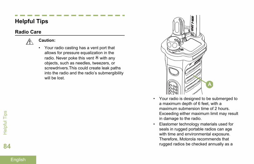
Helpful Tips
Radio CareCaution:
• Your radio casting has a vent port thatallows for pressure equalization in theradio. Never poke this vent with anyobjects, such as needles, tweezers, orscrewdrivers.This could create leak pathsinto the radio and the radio’s submergibilitywill be lost.
A
• Your radio is designed to be submerged toa maximum depth of 6 feet, with amaximum submersion time of 2 hours.Exceeding either maximum limit may resultin damage to the radio.
• Elastomer technology materials used forseals in rugged portable radios can agewith time and environmental exposure.Therefore, Motorola recommends thatrugged radios be checked annually as a
Hel
pful
Tip
s
84
English

preventive measure in order to assure thewatertight integrity of the radio. Motoroladetails the disassembly, test, andreassembly procedures along withnecessary test equipment needed toinspect, maintain and troubleshoot radioseals in the radio’s service manual.
• If the radio battery contact area has beensubmerged in water, dry and clean theradio battery contacts before attaching abattery to the radio. Otherwise, the watercould short-circuit the radio.
• If the radio has been submerged in water,shake the radio well so that any water thatmay be trapped inside the speaker grilleand microphone port can be removed.Otherwise, the water will decrease theaudio quality of the radio.
• Do not disassemble the radio. This coulddamage radio seals and result in leakpaths into the radio. Any radiomaintenance should be performed only bya qualified radio technician.
Cleaning Your Radio
Caution: Do not use solvents to clean yourradio as most chemicals may permanentlydamage the radio housing and textures.
Do not submerge the radio in the detergentsolution.
To clean the external surfaces of your radio, followthe procedure described next.
1 Combine one teaspoon of mild dishwashingdetergent to one gallon of water (0.5% solution).
2 Apply the solution sparingly with a stiff, non-metallic, shortbristled brush, making sure excessdetergent does not get entrapped near theconnectors, controls or crevices. Dry the radiothoroughly with a soft, lint-free cloth.
3 Clean battery contacts with a lint-free cloth toremove dirt or grease.
Proper Ways to Handle the Radio
• Do not pound, drop, or throw the radiounnecessarily. Never carry the radio by theantenna.
Helpful Tips
85
English

• Avoid subjecting the radio to an excess of liquids.Do not submerge the radio unless it is aruggedized.
• Avoid subjecting the radio to corrosives, solventsor chemicals.
• Do not disassemble the radio.• Keep the accessory-connector cover in place until
ready to use the connector. Replace the coverimmediately once the accessory has beendisconnected.
• When charging the radio using a wall mountedcharger, the radio must be turned off. Otherwise,the Man Down Alert and Emergency may beaccidentally triggered.
Radio Service and Repair
Proper repair and maintenance procedures willassure efficient operation and long life for thisproduct. A Motorola maintenance agreement willprovide expert service to keep this and all othercommunication equipment in perfect operatingcondition. A nationwide service organization isprovided by Motorola to support maintenanceservices. Through its maintenance and installationprogram, Motorola makes available the finest serviceto those desiring reliable, continuous communications
on a contract basis. For a contract service agreement,please contact your nearest Motorola service or salesrepresentative, or an authorized Motorola dealer.
Express Service Plus (ESP) is an optional extendedservice coverage plan, which provides for the repairof this product for an additional period of either one ortwo years beyond the normal expiration date of thestandard warranty. For more information about ESP,contact the Motorola Radio Support Center at 3761South Central Avenue, Rockford, IL 61102 (800)227-6772 / (847)725-4200.
Battery CareBattery Charge Status
Your radio can indicate the battery’s charge statusthrough:
• the LED and sounds.• the fuel gauge icon on the display.
LED and Sounds
When your battery is low:
• the LED blinks red when the PTT button ispressed.
Hel
pful
Tip
s
86
English

• you hear a low-battery “chirp” (short, high-pitchedtone).
Fuel Gauge Icons
A blinking fuel gauge icon ( ) is displayed only whenthe battery voltage drops to low level. In this case,replace the battery with a fully charged one.
Gauge Battery Charge
76% to 100% full[3]
51% to 75%[3]
26% to 50%[3]
11% to 25%[3]
Gauge Battery Charge
10% or less (at 10%, the gaugebegins blinking)
Battery Recycling and Disposal
In the U.S. and Canada, Motorola participates in thenationwide Rechargeable Battery RecyclingCorporation (RBRC) program for battery collectionand recycling. Many retailers and dealers participatein this program.
For the of the drop-off facility closest to you, accessRBRC's Internet web site at www.rbrc.com or call1-800-8-BATTERY. This internet site and telephonenumber also provide other useful informationconcerning recycling options for consumers,businesses, and governmental agencies.
3 These are for IMPRES™ battery operation only.
Helpful Tips
87
English

AccessoriesThe accessory link below is for APX radios. Not allaccessories are FCC certified to operate with all APXmodels and/or bandsplits. Please refer to the specificAPX radio price pages for a list of FCC certifiedaccessories or contact your sales representative foraccessory compatibility.
http://www.motorolasolutions.com/APX
Note: GPS only antenna is only used in either asingle band UHF or 700/800 application where thePublic Safety Microphone (PSM) is used with thecorresponding PSM antenna. This antenna is only forGPS reception and cannot be used for receive/transmit operation at UHF, VHF or 700/800. Thisantenna is never to be used on the PSM.
Acc
esso
ries
88
English

Maritime Radio Use in the VHFFrequency Range
Special Channel AssignmentsEmergency Channel
If you are in imminent and grave danger at sea andrequire emergency assistance, use VHF Channel 16to send a distress call to nearby vessels and theUnited States Coast Guard. Transmit the followinginformation, in this order:
1 “MAYDAY, MAYDAY, MAYDAY.”2 “THIS IS _____________________, CALL SIGN
__________.” State the name of the vessel indistress 3 times, followed by the call sign or otheridentification of the vessel, stated 3 times.
3 Repeat “MAYDAY” and the name of the vessel.4 “WE ARE LOCATED AT
_______________________.” State the positionof the vessel in distress, using any information thatwill help responders to locate you, e.g.:
• latitude and longitude• bearing (state whether you are using true or
magnetic north)
• distance to a well-known landmark• vessel course, speed or destination
5 State the nature of the distress.6 Specify what kind of assistance you need.7 State the number of persons on board and the
number needing medical attention, if any.8 Mention any other information that would be
helpful to responders, such as type of vessel,vessel length and/or tonnage, hull color, etc.
9 “OVER.”10 Wait for a response.11 If you do not receive an immediate response,
remain by the radio and repeat the transmission atintervals until you receive a response. Beprepared to follow any instructions given to you.
Non-Commercial Call Channel
For non-commercial transmissions, such as fishingreports, rendezvous arrangements, repair scheduling,or berthing information, use VHF Channel 9.
Operating Frequency RequirementsA radio designated for shipboard use must complywith Federal Communications Commission Rule Part80 as follows:
Maritim
e Radio U
se in the VH
F Frequency Range
89
English

• on ships subject to Part II of Title III of theCommunications Act, the radio must be capable ofoperating on the 156.800 MHz frequency.
• on ships subject to the Safety Convention, theradio must be capable of operating:
• in the simplex mode on the ship stationtransmitting frequencies specified in the156.025 – 157.425 MHz frequency band, and
• in the semiduplex mode on the two frequencychannels specified in the table below.
Note:
Simplex channels 3, 21, 23, 61, 64, 81, 82, and 83cannot be lawfully used by the general public in USwaters.
Additional information about operating requirementsin the Maritime Services can be obtained from the fulltext of FCC Rule Part 80 and from the US CoastGuard.
Table 1: VHF Marine Channel List
ChannelNumber
Frequency (MHz)
Transmit Receive
1 156.050 160.650
2 156.100 160.700
* 156.150 160.750
4 156.200 160.800
5 156.250 160.850
6 156.300 –
7 156.350 160.950
8 156.400 –
9 156.450 156.450
10 156.500 156.500
11 156.550 156.550
12 156.600 156.600
13** 156.650 156.650
14 156.700 156.700
15** 156.750 156.750
16 156.800 156.800
17** 156.850 156.850
Mar
itim
e R
adio
Use
in th
e V
HF
Freq
uenc
y R
ange
90
English

18 156.900 161.500
19 156.950 161.550
20 157.000 161.600
* 157.050 161.650
22 157.100 161.700
* 157.150 161.750
24 157.200 161.800
25 157.250 161.850
26 157.300 161.900
27 157.350 161.950
28 157.400 162.000
60 156.025 160.625
* 156.075 160.675
62 156.125 160.725
63 156.175 160.775
* 156.225 160.825
65 156.275 160.875
66 156.325 160.925
67** 156.375 156.375
68 156.425 156.425
69 156.475 156.475
71 156.575 156.575
72 156.625 –
73 156.675 156.675
74 156.725 156.725
75 *** ***
76 *** ***
77** 156.875 –
78 156.925 161.525
79 156.975 161.575
80 157.025 161.625
* 157.075 161.675
* 157.125 161.725
* 157.175 161.775
Maritim
e Radio U
se in the VH
F Frequency Range
91
English

84 157.225 161.825
85 157.275 161.875
86 157.325 161.925
87 157.375 161.975
88 157.425 162.025
Note:
* Simplex channels 3, 21, 23, 61, 64, 81, 82, and 83cannot be lawfully used by the general public in USwaters.
** Low power (1 W) only.
*** Guard band.
Note: A – in the Receive column indicates that thechannel is transmit only.
Declaration of Compliance for the Use ofDistress and Safety Frequencies
The radio equipment does not employ a modulationother than the internationally adopted modulation formaritime use when it operates on the distress andsafety frequencies specified in RSS-182 Section 7.3.
Technical Parameters for Interfacing ExternalData Sources
RS232 USB SB9600
InputVoltage(Volts
Peak-to-peak)
18V 3.6V 5V
Max DataRate
28 kb/s 12 Mb/s 9.6 kb/s
Impedance 5k ohm 90 ohm 120 ohm
Mar
itim
e R
adio
Use
in th
e V
HF
Freq
uenc
y R
ange
92
English

GlossaryThis glossary is a list of specialized terms used in thismanual.
ACK Acknowledgment ofcommunication.
Active Channel A channel that has traffic on it.
Analog Signal An RF signal that has acontinuous nature rather than apulsed or discrete nature.
ARS Automatic Registration Service
ASTRO 25 Motorola standard for wirelessdigital trunked communications.
ASTROConventional
Motorola standard for wirelessdigital conventionalcommunications.
Autoscan A feature that allows the radioto automatically scan themembers of a scan list.
Bluetooth Bluetooth is an open wirelesstechnology standard forexchanging data over short
distances from fixed andmobile devices with high levelsof security.
Bluetooth Pairing Bluetooth pairing occurs whentwo bluetooth devicesexchanged a passkey to form apaired Bluetooth wirelessconnection.
Call Alert Privately page an individual bysending an audible tone.
Carrier Squelch Feature that responds to thepresence of an RF carrier byopening or unmuting (turningon) a receiver’s audio circuit. Asquelch circuit silences theradio when no signal is beingreceived so that the user doesnot have to listen to “noise”.
Central Controller A software-controlled,computer-driven device thatreceives and generates datafor the trunked radios assignedto it. It monitors and directs the
Glossary
93
English
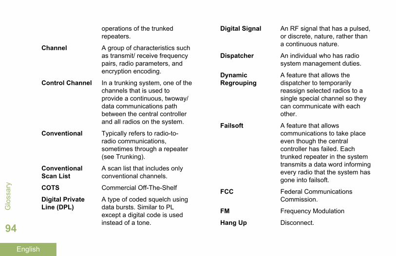
operations of the trunkedrepeaters.
Channel A group of characteristics suchas transmit/ receive frequencypairs, radio parameters, andencryption encoding.
Control Channel In a trunking system, one of thechannels that is used toprovide a continuous, twoway/data communications pathbetween the central controllerand all radios on the system.
Conventional Typically refers to radio-to-radio communications,sometimes through a repeater(see Trunking).
ConventionalScan List
A scan list that includes onlyconventional channels.
COTS Commercial Off-The-Shelf
Digital PrivateLine (DPL)
A type of coded squelch usingdata bursts. Similar to PLexcept a digital code is usedinstead of a tone.
Digital Signal An RF signal that has a pulsed,or discrete, nature, rather thana continuous nature.
Dispatcher An individual who has radiosystem management duties.
DynamicRegrouping
A feature that allows thedispatcher to temporarilyreassign selected radios to asingle special channel so theycan communicate with eachother.
Failsoft A feature that allowscommunications to take placeeven though the centralcontroller has failed. Eachtrunked repeater in the systemtransmits a data word informingevery radio that the system hasgone into failsoft.
FCC Federal CommunicationsCommission.
FM Frequency Modulation
Hang Up Disconnect.
Glo
ssar
y
94
English

Home screen The first display informationafter the radio completes itsself test.
IV&D Integrated Voice and Data
KVL Key-variable loader: A devicefor loading encryption keys intothe radio.
LCD Liquid crystal display.
LED Light-emitting diode.
Li-Ion Lithium ion.
Man Down A life-saving feature thatsenses the radio user may bein trouble by monitoring thewhether the radio is in avertical or horizontal position orwhether the radio ismotionless. When this featureis triggered, the radio alerts theuser with audio and visualalerts. It can also triggerEmergency Alarm the Post-Alert Timer is not cancelled.
MCW Mission Critical Wireless
MDC Motorola Data Communication
Monitor Check channel activity bypressing the Monitor button. Ifthe channel is clear, you hearstatic. If the channel is in use,you hear conversation. It alsoserves as a way to check thevolume level of the radio, sincethe radio “opens the squelch”when the monitor button ispressed.
Multi-SystemTalkgroup ScanList
A scan list that can includeboth talkgroups (trunked) andchannels (conventional).
Network AccessCode
Network Access Code (NAC)operates on digital channels toreduce voice channelinterference between adjacentsystems and sites.
NiMH Nickel-metal-hydride.
Non-Tactical/Revert
The user talks on apreprogrammed emergencychannel. The emergency alarm
Glossary
95
English

is sent out on this samechannel.
OCW Operation Critical Wireless
OTAR Over-the-air rekeying.
Page A one-way alert, with audioand/or display messages.
Personality A set of unique featuresspecific to a radio.
Preprogrammed Refers to a software featurethat has been activated by aqualified radio technician.
Private(Conversation)Call
A feature that lets you have aprivate conversation withanother radio user in thetalkgroup.
Private Line (PL) A sub-audible tone that istransmitted such that onlyreceivers decoding the tonereceives it.
Programmable Refers to a radio control thatcan have a radio featureassigned to it.
PTT Push-To-Talk. The PTT buttonengages the transmitter andputs the radio in transmit(send) operation whenpressed.
Radio Frequency(RF)
The part of the generalfrequency spectrum betweenthe audio and infrared lightregions (about 10 kHz to10,000,000 MHz).
Repeater A conventional radio feature,where you talk through areceive/transmit facility that re-transmits received signals, inorder to improvecommunications range andcoverage.
Selective Switch Any digital P25 traffic havingthe correct Network AccessCode and the correct talkgroup.
Squelch Special electronic circuitry,added to the receiver of aradio, that reduces, or cuts off,
Glo
ssar
y
96
English

unwanted signals before theyare heard in the speaker.
Standby An operating condition wherebythe radio’s speaker is mutedbut still continues to receivedata.
Status Calls Pre-defined text messages thatallow the user to send aconditional message withouttalking.
Tactical/ Non-Revert
The user talks on the channelthat was selected before theradio entered the emergencystate.
Talkaround Bypass a repeater and talkdirectly to another unit for easylocal unit-to-unitcommunications.
Talkgroup An organization or group ofradio users who communicatewith each other using the samecommunication path.
Trunking The automatic sharing ofcommunications paths betweena large number of users (seeConventional).
Trunking PriorityMonitor Scan List
A scan list that includestalkgroups that are all from thesame trunking system.
USK Unique Shadow Key.
Zone A grouping of channels.
Glossary
97
English

Limited Warranty
MOTOROLA COMMUNICATION PRODUCTS
I. WHAT THIS WARRANTY COVERS AND FORHOW LONG:
MOTOROLA SOLUTIONS, INC. (“MOTOROLA”)warrants the MOTOROLA manufacturedCommunication Products listed below (“Product”)against defects in material and workmanship undernormal use and service for a period of time from thedate of purchase as scheduled below:
ASTRO Portable Units One (1) Year
Product Accessories One (1) Year
For LACR region:
ASTRO APX7000XEPortable Units
Three (3) Years
Product Accessories One (1) Year
MOTOROLA, at its option, will at no charge eitherrepair the Product (with new or reconditioned parts),replace it (with a new or reconditioned Product), orrefund the purchase price of the Product during thewarranty period provided it is returned in accordancewith the terms of this warranty. Replaced parts orboards are warranted for the balance of the originalapplicable warranty period. All replaced parts ofProduct shall become the property of MOTOROLA.
This express limited warranty is extended byMOTOROLA to the original end user purchaser onlyand is not assignable or transferable to any otherparty. This is the complete warranty for the Productmanufactured by MOTOROLA. MOTOROLAassumes no obligations or liability for additions ormodifications to this warranty unless made in writingand signed by an officer of MOTOROLA.
Unless made in a separate agreement betweenMOTOROLA and the original end user purchaser,MOTOROLA does not warrant the installation,maintenance or service of the Product.
MOTOROLA cannot be responsible in any way forany ancillary equipment not furnished by MOTOROLAwhich is attached to or used in connection with theProduct, or for operation of the Product with any
Lim
ited
War
rant
y
98
English

ancillary equipment, and all such equipment isexpressly excluded from this warranty. Because eachsystem which may use the Product is unique,MOTOROLA disclaims liability for range, coverage, oroperation of the system as a whole under thiswarranty.
II. GENERAL PROVISIONS:This warranty sets forth the full extent ofMOTOROLA'S responsibilities regarding the Product.Repair, replacement or refund of the purchase price,at MOTOROLA’s option, is the exclusive remedy.THIS WARRANTY IS GIVEN IN LIEU OF ALLOTHER EXPRESS WARRANTIES. IMPLIEDWARRANTIES, INCLUDING WITHOUT LIMITATION,IMPLIED WARRANTIES OF MERCHANTABILITYAND FITNESS FOR A PARTICULAR PURPOSE,ARE LIMITED TO THE DURATION OF THISLIMITED WARRANTY. IN NO EVENT SHALLMOTOROLA BE LIABLE FOR DAMAGES INEXCESS OF THE PURCHASE PRICE OF THEPRODUCT, FOR ANY LOSS OF USE, LOSS OFTIME, INCONVENIENCE, COMMERCIAL LOSS,LOST PROFITS OR SAVINGS OR OTHERINCIDENTAL, SPECIAL OR CONSEQUENTIALDAMAGES ARISING OUT OF THE USE OR
INABILITY TO USE SUCH PRODUCT, TO THEFULL EXTENT SUCH MAY BE DISCLAIMED BYLAW.
III. STATE LAW RIGHTS:SOME STATES DO NOT ALLOW THE EXCLUSIONOR LIMITATION OF INCIDENTAL ORCONSEQUENTIAL DAMAGES OR LIMITATION ONHOW LONG AN IMPLIED WARRANTY LASTS, SOTHE ABOVE LIMITATION OR EXCLUSIONS MAYNOT APPLY.
This warranty gives specific legal rights, and theremay be other rights which may vary from state tostate.
IV. HOW TO GET WARRANTY SERVICE:You must provide proof of purchase (bearing the dateof purchase and Product item serial number) in orderto receive warranty service and, also, deliver or sendthe Product item, transportation and insuranceprepaid, to an authorized warranty service location.Warranty service will be provided by MOTOROLAthrough one of its authorized warranty servicelocations. If you first contact the company which soldyou the Product (e.g., dealer or communication
Limited W
arranty
99
English

service provider), it can facilitate your obtainingwarranty service. You can also call MOTOROLA at1-800-927-2744 US/Canada.
V. WHAT THIS WARRANTY DOES NOTCOVER:
1 Defects or damage resulting from use of theProduct in other than its normal and customarymanner.
2 Defects or damage from misuse, accident, water,or neglect.
3 Defects or damage from improper testing,operation, maintenance, installation, alteration,modification, or adjustment.
4 Breakage or damage to antennas unless causeddirectly by defects in material workmanship.
5 A Product subjected to unauthorized Productmodifications, disassembles or repairs (including,without limitation, the addition to the Product ofnon-MOTOROLA supplied equipment) whichadversely affect performance of the Product orinterfere with MOTOROLA's normal warrantyinspection and testing of the Product to verify anywarranty claim.
6 Product which has had the serial number removedor made illegible.
7 Rechargeable batteries if:
• any of the seals on the battery enclosure ofcells are broken or show evidence oftampering.
• the damage or defect is caused by charging orusing the battery in equipment or service otherthan the Product for which it is specified.
8 Freight costs to the repair depot.9 A Product which, due to illegal or unauthorized
alteration of the software/firmware in the Product,does not function in accordance withMOTOROLA’s published specifications or the FCCcertification labeling in effect for the Product at thetime the Product was initially distributed fromMOTOROLA.
10 Scratches or other cosmetic damage to Productsurfaces that does not affect the operation of theProduct.
11 Normal and customary wear and tear.
VI. PATENT AND SOFTWARE PROVISIONS:MOTOROLA will defend, at its own expense, any suitbrought against the end user purchaser to the extent
Lim
ited
War
rant
y
100
English

that it is based on a claim that the Product or partsinfringe a United States patent, and MOTOROLA willpay those costs and damages finally awarded againstthe end user purchaser in any such suit which areattributable to any such claim, but such defense andpayments are conditioned on the following:
1 that MOTOROLA will be notified promptly inwriting by such purchaser of any notice of suchclaim,
2 that MOTOROLA will have sole control of thedefense of such suit and all negotiations for itssettlement or compromise, and
3 should the Product or parts become, or inMOTOROLA’s opinion be likely to become, thesubject of a claim of infringement of a UnitedStates patent, that such purchaser will permitMOTOROLA, at its option and expense, either toprocure for such purchaser the right to continueusing the Product or parts or to replace or modifythe same so that it becomes non-infringing or togrant such purchaser a credit for the Product orparts as depreciated and accept its return. Thedepreciation will be an equal amount per year overthe lifetime of the Product or parts as establishedby MOTOROLA.
MOTOROLA will have no liability with respect to anyclaim of patent infringement which is based upon thecombination of the Product or parts furnishedhereunder with software, apparatus or devices notfurnished by MOTOROLA, nor will MOTOROLA haveany liability for the use of ancillary equipment orsoftware not furnished by MOTOROLA which isattached to or used in connection with the Product.The foregoing states the entire liability ofMOTOROLA with respect to infringement of patentsby the Product or any parts thereof.
Laws in the United States and other countriespreserve for MOTOROLA certain exclusive rights forcopyrighted MOTOROLA software such as theexclusive rights to reproduce in copies and distributecopies of such MOTOROLA software. MOTOROLAsoftware may be used in only the Product in whichthe software was originally embodied and suchsoftware in such Product may not be replaced,copied, distributed, modified in any way, or used toproduce any derivative thereof. No other useincluding, without limitation, alteration, modification,reproduction, distribution, or reverse engineering ofsuch MOTOROLA software or exercise of rights insuch MOTOROLA software is permitted. No license is
Limited W
arranty
101
English

granted by implication, estoppel or otherwise underMOTOROLA patent rights or copyrights.
VII. GOVERNING LAW:This Warranty is governed by the laws of the State ofIllinois, U.S.A.
VIII. For Australia Only:This warranty is given by Motorola Solutions AustraliaPty Limited (ABN 16 004 742 312) of Tally HoBusiness Park, 10 Wesley Court. Burwood East,Victoria.
Our goods come with guarantees that cannot beexcluded under the Australia Consumer Law. You areentitled to a replacement or refund for a major failureand compensation for any other reasonablyforeseeable loss or damage. You are also entitled tohave the goods repaired or replaced if the goods failto be of acceptable quality and the failure does notamount to a major failure.
Motorola Solutions Australia’s limited warranty aboveis in addition to any rights and remedies you mayhave under the Australian Consumer Law. If you haveany queries, please call Motorola Solutions Australia
at 1800 457 439. You may also visit our website: http://www.motorolasolutions.com/XA-EN/Pages/Contact_Us for the most updated warranty terms.
Lim
ited
War
rant
y
102
English

APX7000XE_M1_BackCover_HalfLetter_P299C.fm Page 1 Monday, November 3, 2014 4:41 PM

APX7000XE_M1_BackCover_HalfLetter_P299C.fm Page 2 Monday, November 3, 2014 4:41 PM
Motorola Solutions, Inc.1303 East Algonquin RoadSchaumburg, Illinois 60196 U.S.A.
MOTOROLA, MOTO, MOTOROLA SOLUTIONS and the Stylized M logo are trademarks or registered trademarks of Motorola Trademark Holdings, LLC and are used under license.All other trademarks are the property of their respective owners. © 2011–2014 Motorola Solutions, Inc. All rights reserved.November 2014.
*68012002071*68012002071-KA