Embed Size (px)
Citation preview
APX 1000
APX™ TWO-WAY RADIOS
APX 1000MODEL 1.5USER GUIDE
APX1000_M1_Front_Cover.fm Page 1 Tuesday, June 10, 2014 11:13 AM

English
Receiving and Transmitting
Sending an Emergency Alarm
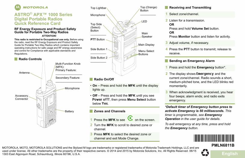
*Default timer of Emergency button press to activate Emergency is 50 milliseconds. This timer is programmable, see Emergency Operation in the user guide for details.To exit emergency at any time, press and hold the Emergency button.
play
e ton
n.
r
ct
ay
nge)
___ 1 Select zone/channel.
2 Listen for a transmission.ORPress and hold Volume Set button.ORPress Monitor button and listen for activity.
3 Adjust volume, if necessary.
4 Press the PTT button to transmit; release to receive.
1 Press and hold the Emergency button*.
2 The display shows Emergency and the current zone/channel. Radio sounds a short, medium-pitched tone, and the LED blinks red momentarily.
3 When acknowledgment is received, you hear four beeps; alarm ends; and radio exits emergency.
*PMLN6811B*PMLN6811B
rola Trademark Holdings, LLC and are ions, Inc. All Rights Reserved. 06/15
QR-Card.fm Page 3 Tuesday, August 18, 2015 4:01 PM
mASTRO® APX™ 1000 Series Digital Portable RadiosQuick Reference CardRF Energy Exposure and Product Safety Guide for Portable Two-Way Radios
ATTENTION!This radio is restricted to Occupational use only. Before using the radio, read the RF Energy Exposure and Product Safety Guide for Portable Two-Way Radios which contains important operating instructions for safe usage and RF energy awareness and control for Compliance with applicable standards and Regulations.
Radio Controls
Radio On/Off
Zones and Channels
Antenna
Accessory Connector
Multi-Function Knob (MFK):Primary Feature:_________________Secondary Feature:_________________
Battery
Microphone• On – Press and hold the MFK until the dis
lights up.
• Off – Press and hold the MFK until you sePower off?, then press Menu Select butbelow Yes.
1 Press the MFK to see on the scree2 Turn the MFK to scroll to desired zone or
channel.3 Press MFK to select the desired zone or
channel and exit Mode Change.
Top Lightbar
Side Button 1__________
PTT Button
Top Side (Select) Button__________ Main
Speake
Microphone
Side Button 2__________
LED
Menu SeleButtons
Main Displ
Top (OraButton_______
MOTOROLA, MOTO, MOTOROLA SOLUTIONS and the Stylized M logo are trademarks or registered trademarks of Motoused under license. All other trademarks are the property of their respective owners. © 2014 and 2015 by Motorola Solut1303 East Algonquin Road, Schaumburg, Illinois 60196, U.S.A.
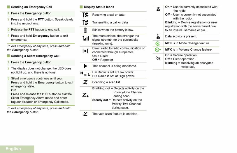
Sending an Emergency Call Display Status Icons On = User is currently associated with the radio.
Off = User is currently not associated with the radio.
Blinking = Device registration or user registration with the server failed due to an invalid username or pin.
Data activity is present.
MFK is in Mode Change feature.
MFK is in Volume Change feature.
On = Secure operation.Off = Clear operation.Blinking = Receiving an encrypted
voice call.
n
o
m
QR-Card.fm Page 4 Tuesday, August 18, 2015 4:01 PM
English
To exit emergency at any time, press and hold the Emergency button.
Sending a Silent Emergency Call
To exit emergency at any time, press and hold the Emergency button.
1 Press the Emergency button.
2 Press and hold the PTT button. Speak clearly into the microphone.
3 Release the PTT button to end call.
4 Press and hold Emergency button to exit emergency.
1 Press the Emergency button.
2 The display does not change; the LED does not light up, and there is no tone.
3 Silent emergency continues until you:Press and hold the Emergency button to exit emergency state.ORPress and release the PTT button to exit the Silent Emergency Alarm mode and enter regular dispatch or Emergency Call mode.
Receiving a call or data
Transmitting a call or data
Blinks when the battery is low.
The more stripes, the stronger the signal strength for the current site (trunking only).Direct radio to radio communication or connected through a repeater.On = DirectOff = Repeater
This channel is being monitored.
L = Radio is set at Low power.H = Radio is set at High power.
Scanning a scan list.
Blinking dot = Detects activity on the Priority-One Channel during scan.
Steady dot = Detects activity on the Priority-Two Channel during scan.
The vote scan feature is enabled.
ut8V
O
MHOR .i
j
k
ContentsDeclaration of Conformity......................... 6
Important Safety Information..........8
Software Version..............................9Notice to Users (FCC and Industry
Canada)......................................................9
Consignes de sécuritéimportantes.................................10
Version logicielle........................... 11Avis aux utilisateurs (FCC et Industrie
Canada)....................................................11
Computer Software Copyrights....12
Documentation Copyrights...........13
Disclaimer.......................................14
Getting Started...............................15How to Use This Guide..................................15Notations Used in This Manual......................15Additional Performance Enhancement.......... 15
Dynamic System Resilience (DSR).... 15CrossTalk Prevention..........................15Conventional Talkgroup and Radio
Scan Enhancements......................16What Your Dealer/System Administrator
Can Tell You.............................................16
Preparing Your Radio for Use.......18Charging the Battery......................................18Attaching the Battery..................................... 18Attaching the Antenna................................... 19Removing and Attaching the Accessory
Connector Cover...................................... 20
Contents
1
English
Attaching the Belt Clip................................... 21Turning On the Radio.................................... 21Adjusting the Volume.....................................22
Identifying Radio Controls............24Radio Parts and Controls...............................24Programmable Features................................25
Assignable Radio Functions............... 25Assignable Settings or Utility
Functions....................................... 27Accessing the Preprogrammed Functions.....27
Menu Select Buttons...........................28Multi-Function Knob (MFK).................28
Push-To-Talk (PTT) Button............................29
Identifying Status Indicators.........30Status Icons...................................................30LED Indicator.................................................32Top Lightbar Indicator....................................33Intelligent Lighting Indicators......................... 34Alert Tones.................................................... 35Phone Call Displays and Alerts..................... 38
General Radio Operation...............39Selecting a Zone............................................39Selecting a Radio Channel............................ 39Mode Select Feature..................................... 40
Saving a Zone and a Channel to aSoftkey...........................................40
Saving a Zone and a Channel to aButton............................................ 40
Receiving and Responding to a Radio Call... 41Receiving and Responding to a
Talkgroup Call................................41Receiving and Responding to a
Private Call (Trunking Only)...........41Receiving and Responding to a
Telephone Call (Trunking Only).....42Switching Between Repeater or Direct
Operation Button...................................... 43Monitor Feature............................................. 43
Monitoring a Channel..........................43Monitoring Conventional Mode........... 44
Advanced Features........................45Advanced Call Features................................ 45
Con
tent
s
2
English
Selective Call (ASTROConventional Only)........................ 45
Responding to the DynamicRegrouping Feature (TrunkingOnly).............................................. 45
Scan Lists...................................................... 46Viewing a Scan List.............................47Viewing and Changing the Priority
Status.............................................47Scan...............................................................47
Turning Scan On or Off.......................47Making a Dynamic Priority Change
(Conventional Scan Only)..............48Deleting a Nuisance Channel............. 48Restoring a Nuisance Channel........... 48
Call Alert Paging............................................49Receiving a Call Alert Page................ 49
Emergency Operation....................................49Sending an Emergency Alarm............ 50Sending an Emergency Call
(Trunking Only).............................. 51Sending an Emergency Alarm with
Emergency Call............................. 51Sending a Silent Emergency Alarm.... 52Change of Channels during
Emergency.....................................52Emergency Keep-Alive Feature..........53
Automatic Registration Service (ARS)...........53Selecting or Changing the ARS
Mode..............................................53Global Positioning System / Global
Navigation Satellite System......................54GPS Operation....................................54GPS Performance Enhancement........55Peer-Location on the Display
(ASTRO Conventional only).......... 56Geofence (ASTRO 25 Trunking System)...... 56
Entering the Geofence Area............... 57Trunking System Controls............................. 58
Operating in Failsoft System...............58Out-of-Range Radio............................58Site Trunking Feature......................... 59Locking and Unlocking a Site..............59Site Display and Search Button.......... 59
Over-the-Air Programming (POP 25,ASTRO 25, ASTRO Conventional)...........60
Responding to the Notification ofUpgrade......................................... 60
Voice Announcement.....................................61Utilities........................................................... 62
Selecting the Power Level.................. 62Enabling and Disabling the Radio
Alias............................................... 63Controlling the Display Backlight........ 63
Contents
3
English
Locking and Unlocking the Controls... 64Turning the Controls and Buttons
Tones On or Off............................. 64Turning Voice Mute On or Off.............64Using the Time-Out Timer...................65Using Conventional Squelch
Operation Features........................65Using the PL Defeat Feature.............. 66Digital PTT ID Support........................66Smart PTT Feature (Conventional
Only).............................................. 66Viewing the IP Address.......................67Transmit Inhibit................................... 67
Helpful Tips.................................... 69Radio Care.....................................................69
Cleaning Your Radio...........................69Proper Ways to Handle the Radio...... 70Radio Service and Repair...................70
Battery Care...................................................70Battery Charge Status.........................70Battery Recycling and Disposal.......... 71
Accessories....................................72
Maritime Radio Use in the VHFFrequency Range....................... 73
Special Channel Assignments.......................73Emergency Channel........................... 73Non-Commercial Call Channel........... 73
Operating Frequency Requirements..............73Declaration of Compliance for the Use of
Distress and Safety Frequencies..............76Technical Parameters for Interfacing
External Data Sources..............................76
Glossary..........................................77
Limited Warranty............................82MOTOROLA COMMUNICATION
PRODUCTS............................................. 82I. WHAT THIS WARRANTY COVERS
AND FOR HOW LONG:........................... 82II. GENERAL PROVISIONS:......................... 83III. STATE LAW RIGHTS:..............................84IV. HOW TO GET WARRANTY SERVICE:...84
Con
tent
s
4
English
V. WHAT THIS WARRANTY DOES NOTCOVER:....................................................84
VI. PATENT AND SOFTWAREPROVISIONS:.......................................... 85
VII. GOVERNING LAW:.................................86VIII. For Australia Only...................................86
Contents
5
English
Declaration of ConformityThis declaration is applicable to your radio only if your radio is labeled with the FCC logo shown below.
Declaration of Conformity
Per FCC CFR 47 Part 2 Section 2.1077(a)
Responsible Party
Name: Motorola Solutions, Inc.
Address: 1303 East Algonquin Road, Schaumburg, IL 60196-1078, U.S.A.
Phone Number: 1-800-927-2744
Hereby declares that the product:
Model Name: APX 1000
conforms to the following regulations:
FCC Part 15, subpart B, section 15.107(a), 15.107(d) and section 15.109(a)
Dec
lara
tion
of C
onfo
rmity
6
English
Class B Digital Device
As a personal computer peripheral, this device complies with Part 15 of the FCC Rules. Operation is subject to thefollowing two conditions:
1 This device may not cause harmful interference, and2 This device must accept any interference received, including interference that may cause undesired operation.
Note:This equipment has been tested and found to comply with the limits for a Class B digital device, pursuantto part 15 of the FCC Rules. These limits are designed to provide reasonable protection against harmfulinterference in a residential installation. This equipment generates, uses and can radiate radio frequencyenergy and, if not installed and used in accordance with the instructions, may cause harmful interferenceto radio communications. However, there is no guarantee that interference will not occur in a particular in-stallation.
If this equipment does cause harmful interference to radio or television reception, which can be determinedby turning the equipment off and on, the user is encouraged to try to correct the interference by one ormore of the following measures:
• Reorient or relocate the receiving antenna.• Increase the separation between the equipment and receiver.• Connect the equipment into an outlet on a circuit different from that to which the receiver is connected.• Consult the dealer or an experienced radio or TV technician for help.
Declaration of C
onformity
7
English
Important Safety InformationRF Energy Exposure and Product Safety Guidefor Portable Two-Way Radios
ATTENTION!
This radio is restricted to Occupational use only.Before using the radio, read the RF Energy Exposureand Product Safety Guide for Portable Two-WayRadios which contains important operatinginstructions for safe usage and RF energy awarenessand control for Compliance with applicable standardsand Regulations.
For a list of Motorola-approved antennas, batteries,and other accessories, visit the following website:
http://www.motorolasolutions.com/APX
Under Industry Canada regulations, this radiotransmitter may only operate using an antenna of atype and maximum (or lesser) gain approved for thetransmitter by Industry Canada. To reduce potentialradio interference to other users, the antenna typeand its gain should be so chosen that the equivalentisotropically radiated power (e.i.r.p.) is not more thanthat necessary for successful communication.
This radio transmitter has been approved by IndustryCanada to operate with Motorola-approved antennawith the maximum permissible gain and requiredantenna impedance for each antenna type indicated.Antenna types not included in this list, having a gaingreater than the maximum gain indicated for thattype, are strictly prohibited for use with this device.
Impo
rtant
Saf
ety
Info
rmat
ion
8
English
Software VersionAll the features described in the following sections aresupported by the software version R14.00.00 or later.
See Accessing the Radio Information to determinethe software version of your radio.
Check with your dealer or system administrator formore details of all the features supported.
Notice to Users (FCC and Industry Canada)This device complies with Part 15 of the FCC rulesand RSS 210 of the Industry Canada rules per thefollowing conditions:
• This device may not cause harmful interference.• This device must accept any interference
received, including interference that may causeundesired operation.
• Changes or modifications made to this device, notexpressly approved by Motorola, could void theauthority of the user to operate this equipment.
Softw
are Version
9
English
Consignes de sécurité importantesRadios bidirectionnelles portatives : expositionaux radiofréquences et sécurité du produit
ATTENTION!
Cette radio ne doit être utilisée qu'à des finsprofessionnelles. Avant d'utiliser la radio, lisez leguide Radios bidirectionnelles portatives : expositionaux radiofréquences et sécurité du produit, quicontient d'importantes instructions de fonctionnementpour une utilisation sécuritaire et des informations surl'exposition aux fréquences radioélectriques, dans lebut d’assurer votre conformité aux normes etrèglements en vigueur.
Visitez le site Web suivant pour obtenir la liste desantennes, des batteries et des autres accessoiresapprouvés par Motorola :
http://www.motorolasolutions.com/APX
Selon la réglementation d'Industrie Canada, cetémetteur radio ne peut être utilisé qu'avec uneantenne dont le type et le gain maximal (ou minimal)sont approuvés par Industrie Canada pour cetémetteur. Afin de limiter les interférences radio pour
les autres utilisateurs, le type et le gain de l'antennedoivent être choisis de façon à ce que la puissanceisotrope rayonnée équivalente (P.I.R.E.) ne soit pasplus forte qu'il ne le faut pour établir lacommunication.
Cet émetteur radio a été approuvé par IndustrieCanada pour utilisation avec une antenne approuvéepar Motorola offrant le gain maximal autorisé etl'impédance requise pour le type d'antenne indiqué. Ilest strictement interdit d'utiliser avec cet appareil touttype d'antenne ne figurant pas dans cette liste etprésentant un gain supérieur au maximum indiquépour le type.
Con
sign
es d
e sé
curit
é im
porta
ntes
10
English
Version logicielleToutes les fonctions décrites dans les sectionssuivantes sont prises en charge par la versionR14.00.00 ou les versions ultérieures du logiciel de laradio.
Pour obtenir davantage de renseignements à proposdes fonctions prises en charge, adressez-vous àvotre détaillant ou à votre administrateur de système.
Avis aux utilisateurs (FCC et IndustrieCanada)
Cet appareil est conforme à la Partie 15 desrèglements de la FCC et RSS 210 du règlementd'Industrie Canada selon les conditions énuméréesci-dessous:
• Ce dispositif ne doit pas causer d'interférencesnuisibles.
• Cet appareil doit accepter toute interférencereçue, y compris les interférences qui peuventperturber le fonctionnement.
• Les changements ou les modifications apportéesà ce dispositif, non expressément approuvées par
Motorola, peuvent annuler le droit de l'utilisateur àutiliser cet équipement.
Version logicielle
11
English
Computer Software CopyrightsThe Motorola products described in this manual mayinclude copyrighted Motorola computer programsstored in semiconductor memories or other media.Laws in the United States and other countriespreserve for Motorola certain exclusive rights forcopyrighted computer programs including, but notlimited to, the exclusive right to copy or reproduce inany form the copyrighted computer program.Accordingly, any copyrighted Motorola computerprograms contained in the Motorola productsdescribed in this manual may not be copied,reproduced, modified, reverse-engineered, ordistributed in any manner without the express writtenpermission of Motorola. Furthermore, the purchase ofMotorola products shall not be deemed to grant eitherdirectly or by implication, estoppel, or otherwise, anylicense under the copyrights, patents or patentapplications of Motorola, except for the normal non-exclusive license to use that arises by operation oflaw in the sale of a product.
Com
pute
r Sof
twar
e C
opyr
ight
s
12
English
Documentation CopyrightsNo duplication or distribution of this document or anyportion thereof shall take place without the expresswritten permission of Motorola. No part of this manualmay be reproduced, distributed, or transmitted in anyform or by any means, electronic or mechanical, forany purpose without the express written permission ofMotorola.
Docum
entation Copyrights
13
English
DisclaimerThe information in this document is carefullyexamined, and is believed to be entirely reliable.However, no responsibility is assumed forinaccuracies. Furthermore, Motorola reserves theright to make changes to any products herein toimprove readability, function, or design. Motoroladoes not assume any liability arising out of theapplications or use of any product or circuit describedherein; nor does it cover any license under its patentrights, nor the rights of others.
Dis
clai
mer
14
English
Getting Started
How to Use This GuideThis User Guide covers the basic operation of theAPX Portables.
However, your dealer or system administrator mayhave customized your radio for your specific needs.Check with your dealer or system administrator formore information.
Notations Used in This ManualThroughout the text in this publication, you will noticethe use of Warning, Caution, and Note. Thesenotations are used to emphasize that safety hazardsexist, and the care that must be taken or observed.
Warning:An operational procedure, practice, orcondition and so on, which may result in injuryor death if not carefully observed.
Caution:An operational procedure, practice, orcondition and so on, which may result in
damage to the equipment if not carefullyobserved.
Note:An operational procedure, practice, orcondition and so on, which is essential toemphasize.
Additional Performance EnhancementThe following performance enhancements are someof the latest creations designed to enhance thesecurity, quality and efficiency of the radios.
Dynamic System Resilience (DSR)
DSR ensures the radio system is seamlesslyswitched to a backup master site dynamically in caseof system failure. DSR also provides additionalindication e.g. failure detection, fault recovery, andredundancy within the system to address to the userin need. Mechanisms related to the Integrated Voiceand Data (IV&D) or data centric are all supported byDSR.
CrossTalk Prevention
This feature prevents crosstalk scenarios fromhappening, especially when a wideband antenna is
Getting S
tarted
15
English
used. This feature allows the adjustment of theinternal SSI clock rate of the radio. This subsequentlyreduces the possibility of radio frequency interferingspurs and prevents the issues of crosstalk.
Conventional Talkgroup and Radio ScanEnhancements
A few enhancements have been made to theConventional Talkgroup at the system. Theseenhancements improve the Scan feature operationsignificantly when multiple agencies are using asingle conventional radio frequency channel. Theseenhancements allow users to use Selective Squelchto operate on only the subset of talkgroups that arerelevant to the users rather than all talkgroups on thechannel. These Scan improvements have been madeto eliminate the audio holes that were present and toturn on the busy LED when activity is present on thechannel. Mixed Vote Scan and StandardConventional Scan configurations are supported.Priority Operation is also supported.
Up to 30 different talkgroups can be supported usingconventional channels. A maximum of four talkgroupscan be supported when Vote Scan channels arebeing used.
Smart PTT is supported with this enhancement asSmart PTT prevents users from transmitting whileother users are on the channel.
Note:User Selectable Talkgroups are notcompatible with this Conventional TalkgroupEnhancement.
What Your Dealer/System Administrator CanTell You
Check with your dealer or system administrator forthe correct radio settings, if the radio is to beoperated in extreme temperatures (less than -30 °Cor more than +60 °C).
You can consult your dealer or system administratorabout the following:
• Is your radio programmed with any presetconventional channels?
• Which buttons have been programmed to accessother features?
• What optional accessories may suit your needs?
Get
ting
Sta
rted
16
English
Note:Specifications may vary for different radiomodels. Check with your dealer or systemadministrator for more information.
Getting S
tarted
17
English
Preparing Your Radio for UseThis section provides simple instructions to prepareyour radio for use.
Charging the BatteryWarning:To avoid a possible explosion:
• Do not replace the battery in any arealabeled hazardous atmosphere.
• Do not discard batteries in a fire.
The Motorola-approved battery shipped with yourradio is uncharged. Prior to using a new battery,charge it for a minimum of 16 hours to ensureoptimum capacity and performance. For a list ofMotorola-authorized batteries and chargers availablefor use with your radio, see Accessories on page72.
Note:When charging a battery attached to a radio,turn the radio off to ensure a full charge.
To charge the battery, place the battery (with orwithout the radio) in a Motorola-approved charger.
The LED on the charger indicates the chargingprogress; see the charger user guide.
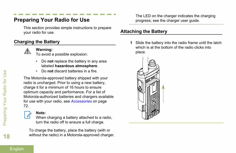
Attaching the Battery
1 Slide the battery into the radio frame until the latchwhich is at the bottom of the radio clicks intoplace.
Pre
parin
g Y
our R
adio
for U
se
18
English
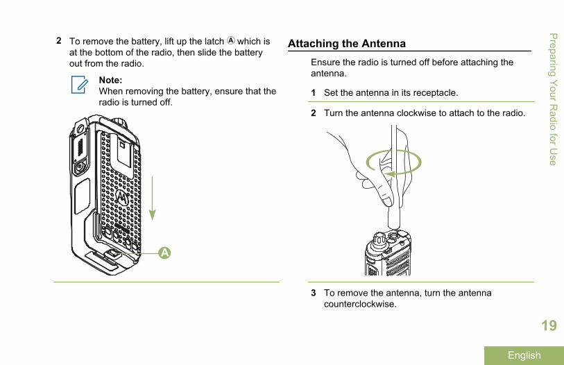
2 To remove the battery, lift up the latch which isat the bottom of the radio, then slide the batteryout from the radio.
Note:When removing the battery, ensure that theradio is turned off.
A
Attaching the AntennaEnsure the radio is turned off before attaching theantenna.
1 Set the antenna in its receptacle.
2 Turn the antenna clockwise to attach to the radio.
3 To remove the antenna, turn the antennacounterclockwise.
Preparing Y
our Radio for U
se
19
English
Note:When removing the antenna, ensure thatthe radio is turned off.
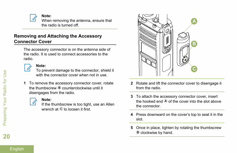
Removing and Attaching the AccessoryConnector Cover
The accessory connector is on the antenna side ofthe radio. It is used to connect accessories to theradio.
Note:To prevent damage to the connector, shield itwith the connector cover when not in use.
1 To remove the accessory connector cover, rotatethe thumbscrew counterclockwise until itdisengages from the radio.
Note:If the thumbscrew is too tight, use an Allenwrench at to loosen it first.
A
B
C
2 Rotate and lift the connector cover to disengage itfrom the radio.
3 To attach the accessory connector cover, insertthe hooked end of the cover into the slot abovethe connector.
4 Press downward on the cover’s top to seat it in theslot.
5 Once in place, tighten by rotating the thumbscrew clockwise by hand.
Pre
parin
g Y
our R
adio
for U
se
20
English
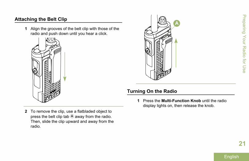
Attaching the Belt Clip
1 Align the grooves of the belt clip with those of theradio and push down until you hear a click.
2 To remove the clip, use a flatbladed object topress the belt clip tab away from the radio.Then, slide the clip upward and away from theradio.
A
Turning On the Radio
1 Press the Multi-Function Knob until the radiodisplay lights on, then release the knob.
Preparing Y
our Radio for U
se
21
English
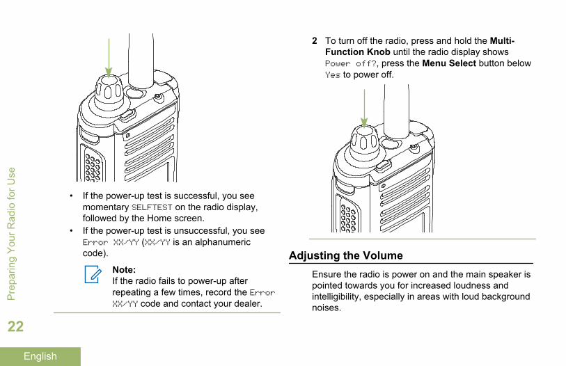
• If the power-up test is successful, you seemomentary SELFTEST on the radio display,followed by the Home screen.
• If the power-up test is unsuccessful, you seeError XX/YY (XX/YY is an alphanumericcode).
Note:If the radio fails to power-up afterrepeating a few times, record the ErrorXX/YY code and contact your dealer.
2 To turn off the radio, press and hold the Multi-Function Knob until the radio display showsPower off?, press the Menu Select button belowYes to power off.
Adjusting the VolumeEnsure the radio is power on and the main speaker ispointed towards you for increased loudness andintelligibility, especially in areas with loud backgroundnoises.
Pre
parin
g Y
our R
adio
for U
se
22
English
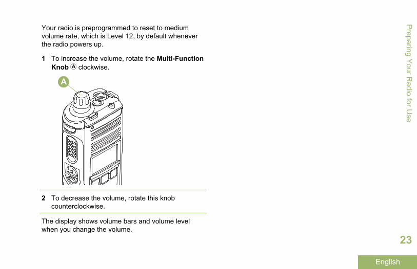
Your radio is preprogrammed to reset to mediumvolume rate, which is Level 12, by default wheneverthe radio powers up.
1 To increase the volume, rotate the Multi-FunctionKnob clockwise.
A
2 To decrease the volume, rotate this knobcounterclockwise.
The display shows volume bars and volume levelwhen you change the volume.
Preparing Y
our Radio for U
se
23
English
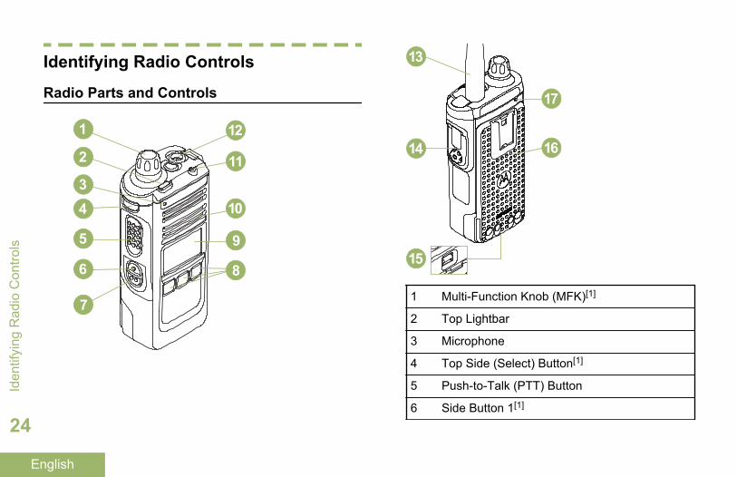
Identifying Radio Controls
Radio Parts and Controls
1
2
34
5
6
7
12
11
10
9
8
13
17
1614
15
1 Multi-Function Knob (MFK)[1]
2 Top Lightbar
3 Microphone
4 Top Side (Select) Button[1]
5 Push-to-Talk (PTT) Button
6 Side Button 1[1]
Iden
tifyi
ng R
adio
Con
trols
24
English
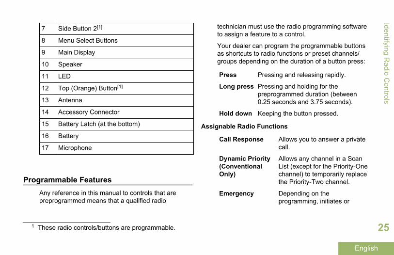
7 Side Button 2[1]
8 Menu Select Buttons
9 Main Display
10 Speaker
11 LED
12 Top (Orange) Button[1]
13 Antenna
14 Accessory Connector
15 Battery Latch (at the bottom)
16 Battery
17 Microphone
Programmable FeaturesAny reference in this manual to controls that arepreprogrammed means that a qualified radio
technician must use the radio programming softwareto assign a feature to a control.
Your dealer can program the programmable buttonsas shortcuts to radio functions or preset channels/groups depending on the duration of a button press:
Press Pressing and releasing rapidly.
Long press Pressing and holding for thepreprogrammed duration (between0.25 seconds and 3.75 seconds).
Hold down Keeping the button pressed.
Assignable Radio Functions
Call Response Allows you to answer a privatecall.
Dynamic Priority(ConventionalOnly)
Allows any channel in a ScanList (except for the Priority-Onechannel) to temporarily replacethe Priority-Two channel.
Emergency Depending on theprogramming, initiates or
1 These radio controls/buttons are programmable.
Identifying Radio C
ontrols
25
English
cancels an emergency alarm orcall.
Internet ProtocolAddress
Display the Internet Protocol(IP) address, device name andstatus of the radio.
Mode Select Long-press programs a buttonwith the current zone andchannel of the radio; onceprogrammed, the short-press ofthat button changes the radiozone channel to theprogrammed zone andchannel.
Monitor(ConventionalOnly)
Monitors a selected channel forall radio traffic until function isdisabled.
Nuisance Delete Temporarily removes anunwanted channel, except forpriority channels or thedesignated transmit channelfrom the scan list.
Private LineDefeat
Overrides any coded squelch(DPL or PL) that ispreprogrammed to a channel.
(ConventionalOnly)
Repeater AccessButton (RAB)(ConventionalOnly)
Allows user to manually send arepeater access codeword.
ReprogramRequest(Trunking Only)
Notifies the dispatcher youwant a new dynamicregrouping assignment.
Request-To-Talk(ConventionalOnly)
Notifies the dispatcher youwant to send a voice call.
Scan Toggles scan on or off.
Scan ListProgramming
Selects the scan list for editing(by long press on the Scanbutton).
SecureTransmissionSelect(Conventionaland Trunking)
Toggles the SecureTransmission On or Off whenthe Secure/Clear Strappingfields is set to Select for thecurrent channel and when theradio is model/option capable.
Iden
tifyi
ng R
adio
Con
trols
26
English
Site Display/Search (TrunkingOnly)
Displays the current site ID andRSSI value; performs sitesearch for Automatic MultipleSite Select (AMSS) orSmartZone operation.
Site Lock/Unlock(Trunking Only)
Locks onto a specific site.
Talkaround/Direct(ConventionalOnly)
Toggles between using arepeater and communicatingdirectly with another radio.
Assignable Settings or Utility Functions
Keypad/ControlsLock
Locks or unlocks the keypad,programmable buttons,switches or rotary knobs.
Light/Flip Press the button to toggle thedisplay backlight on or off;press and hold the button toreverse the content of the topdisplay.
VoiceAnnouncement
Audibly indicates the currentfeature mode, Zone orChannel the user has justassigned.
Voice Mute Toggles voice mute on or off.
Volume Set Tone Sets the volume set tone.
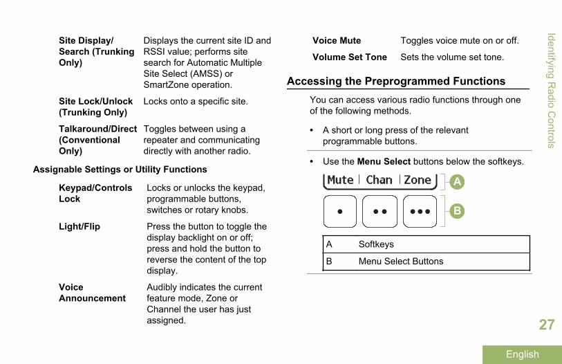
Accessing the Preprogrammed FunctionsYou can access various radio functions through oneof the following methods.
• A short or long press of the relevantprogrammable buttons.
• Use the Menu Select buttons below the softkeys.
A
B
A Softkeys
B Menu Select Buttons
Identifying Radio C
ontrols
27
English
Menu Select Buttons
Note:Check with your dealer or systemadministrator for the list of features activatedin your radio.
Use the Menu Select button to access the menuentry of your radio feature. Your radio may bepreprogrammed differently from the followingexample, but the steps for selecting a channel mayappear as shown below:
Press the Menu Select button directly below Chan.
Multi-Function Knob (MFK)
MFK is the on/off button of your radio. See TurningOn the Radio on page 21 for the procedure to powerup and down the radio.
In addition, there are programmable featuresavailable for MFK. The two programmable featuresare as the following.
ModeChange
Turn MFK to scroll the channel or zonelist.
VolumeChange
Turn MFK to increase or decrease thevolume level of the speaker. Fast turnof MFK makes coarse tuning of thevolume level; slow turn of MFK makesfine tuning of the volume level. Thedisplay shows the volume level andbars to indicate the current level. Thelevel of last selected volume before theradio powers down remains the samewhen the radio powers up.
The radio by default is set to use the primary feature.Short presses of MFK toggle it to work on either thesecondary or primary feature.
The main display only shows the icon of secondaryfeature; the main display does not show the icon ofprimary feature.
The secondary feature has an inactivity timer. Thistimer starts when the secondary feature is left idle.Your radio returns to primary feature when this timerexpires.
If the MFK is set to operate only one feature besidesOn/Off the radio, Volume Change should be the onlyfeature applied to MFK.
Iden
tifyi
ng R
adio
Con
trols
28
English
Consult your dealer or system administrator for thebest options available for MFK.
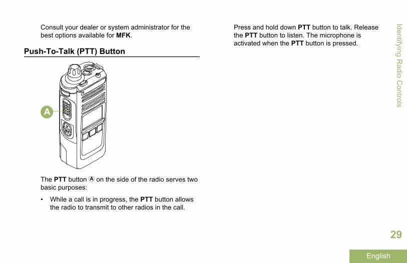
Push-To-Talk (PTT) Button
A
The PTT button on the side of the radio serves twobasic purposes:
• While a call is in progress, the PTT button allowsthe radio to transmit to other radios in the call.
Press and hold down PTT button to talk. Releasethe PTT button to listen. The microphone isactivated when the PTT button is pressed.
Identifying Radio C
ontrols
29
English
Identifying Status Indicators
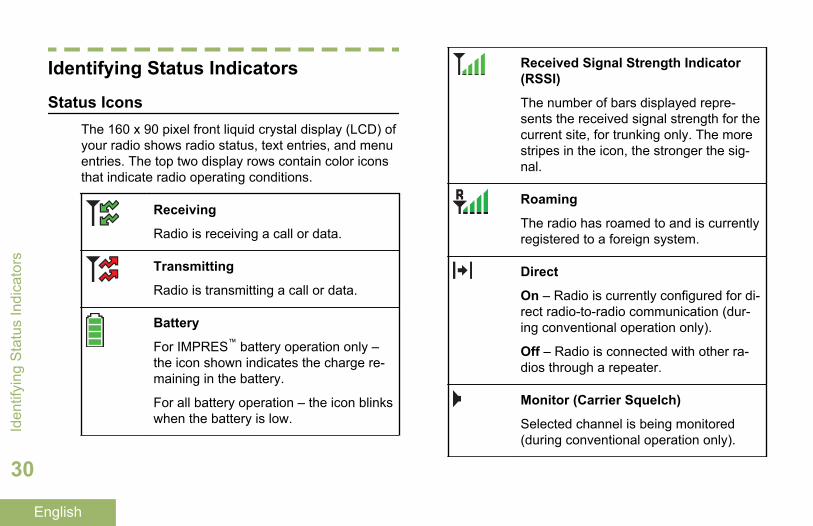
Status IconsThe 160 x 90 pixel front liquid crystal display (LCD) ofyour radio shows radio status, text entries, and menuentries. The top two display rows contain color iconsthat indicate radio operating conditions.
Receiving
Radio is receiving a call or data.
Transmitting
Radio is transmitting a call or data.
Battery
For IMPRES™ battery operation only –the icon shown indicates the charge re-maining in the battery.
For all battery operation – the icon blinkswhen the battery is low.
Received Signal Strength Indicator(RSSI)
The number of bars displayed repre-sents the received signal strength for thecurrent site, for trunking only. The morestripes in the icon, the stronger the sig-nal.
Roaming
The radio has roamed to and is currentlyregistered to a foreign system.
Direct
On – Radio is currently configured for di-rect radio-to-radio communication (dur-ing conventional operation only).
Off – Radio is connected with other ra-dios through a repeater.
Monitor (Carrier Squelch)
Selected channel is being monitored(during conventional operation only).
Iden
tifyi
ng S
tatu
s In
dica
tors
30
English
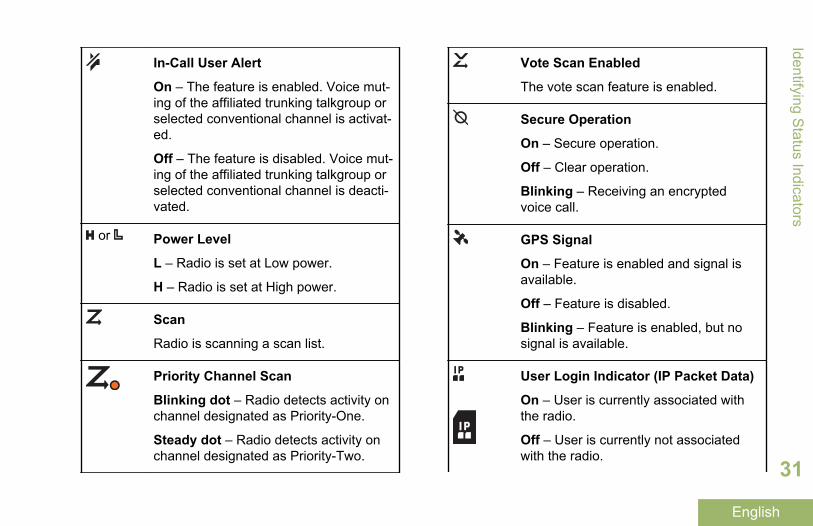
In-Call User Alert
On – The feature is enabled. Voice mut-ing of the affiliated trunking talkgroup orselected conventional channel is activat-ed.
Off – The feature is disabled. Voice mut-ing of the affiliated trunking talkgroup orselected conventional channel is deacti-vated.
or Power Level
L – Radio is set at Low power.
H – Radio is set at High power.
Scan
Radio is scanning a scan list.
Priority Channel Scan
Blinking dot – Radio detects activity onchannel designated as Priority-One.
Steady dot – Radio detects activity onchannel designated as Priority-Two.
Vote Scan Enabled
The vote scan feature is enabled.
Secure Operation
On – Secure operation.
Off – Clear operation.
Blinking – Receiving an encryptedvoice call.
GPS Signal
On – Feature is enabled and signal isavailable.
Off – Feature is disabled.
Blinking – Feature is enabled, but nosignal is available.
User Login Indicator (IP Packet Data)
On – User is currently associated withthe radio.
Off – User is currently not associatedwith the radio.
Identifying Status Indicators
31
English
Blinking – Device registration or userregistration with the server failed due toan invalid username or pin.
Inverted – User successfully login to thesecured IP Packet Data.
Data Activity
Data activity is present.
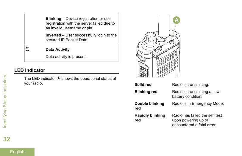
LED IndicatorThe LED indicator shows the operational status ofyour radio.
A
Solid red Radio is transmitting.
Blinking red Radio is transmitting at lowbattery condition.
Double blinkingred
Radio is in Emergency Mode.
Rapidly blinkingred
Radio has failed the self testupon powering up orencountered a fatal error.Id
entif
ying
Sta
tus
Indi
cato
rs
32
English
Solid yellow(ConventionalOnly)
Channel is busy.
Blinking yellow Radio is receiving a securedtransmission.
Solid green Radio is powering up, or is ona non-priority channel while inthe Scan List Programmingmode.
Blinking green Radio is receiving an individualor telephone call, or is on aPriority-Two channel while inthe Scan List Programmingmode.
Rapidly blinkinggreen
Radio is on a Priority-Onechannel while in the Scan ListProgramming mode.
Note:No LED indication when the radio receives aclear (non-secured) transmission in trunkingMode. LED indication can be preprogramed byqualified technician to be permanentlydisabled. Consult your dealer for furtherdetails if you want to disable it.
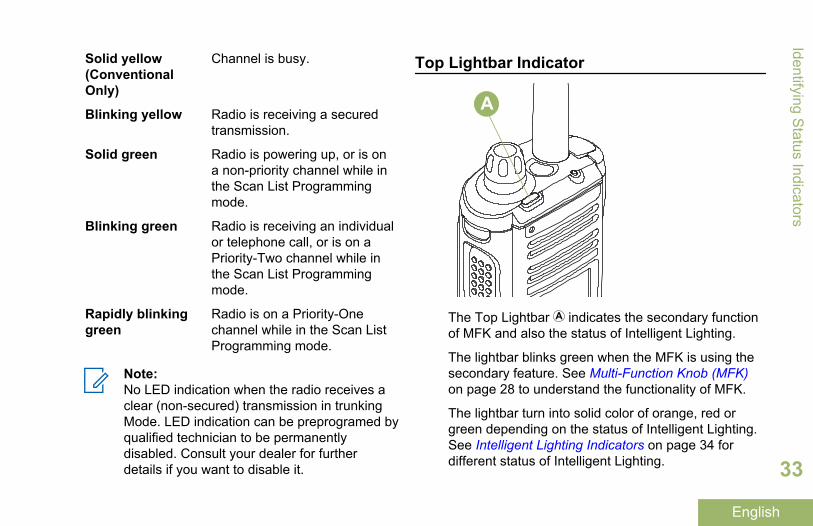
Top Lightbar Indicator
A
The Top Lightbar indicates the secondary functionof MFK and also the status of Intelligent Lighting.
The lightbar blinks green when the MFK is using thesecondary feature. See Multi-Function Knob (MFK)on page 28 to understand the functionality of MFK.
The lightbar turn into solid color of orange, red orgreen depending on the status of Intelligent Lighting.See Intelligent Lighting Indicators on page 34 fordifferent status of Intelligent Lighting.
Identifying Status Indicators
33
English
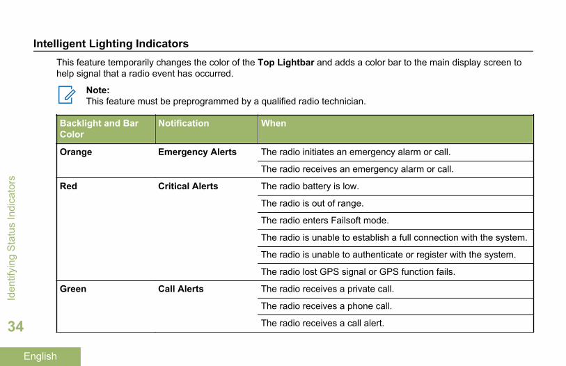
Intelligent Lighting IndicatorsThis feature temporarily changes the color of the Top Lightbar and adds a color bar to the main display screen tohelp signal that a radio event has occurred.
Note:This feature must be preprogrammed by a qualified radio technician.
Backlight and BarColor
Notification When
Orange Emergency Alerts The radio initiates an emergency alarm or call.
The radio receives an emergency alarm or call.
Red Critical Alerts The radio battery is low.
The radio is out of range.
The radio enters Failsoft mode.
The radio is unable to establish a full connection with the system.
The radio is unable to authenticate or register with the system.
The radio lost GPS signal or GPS function fails.
Green Call Alerts The radio receives a private call.
The radio receives a phone call.
The radio receives a call alert.
Iden
tifyi
ng S
tatu
s In
dica
tors
34
English
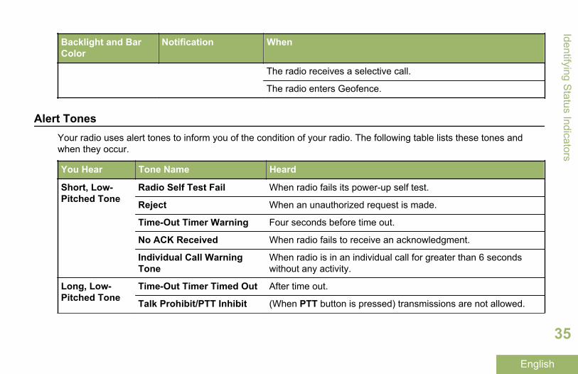
Backlight and BarColor
Notification When
The radio receives a selective call.
The radio enters Geofence.
Alert TonesYour radio uses alert tones to inform you of the condition of your radio. The following table lists these tones andwhen they occur.
You Hear Tone Name Heard
Short, Low-Pitched Tone
Radio Self Test Fail When radio fails its power-up self test.
Reject When an unauthorized request is made.
Time-Out Timer Warning Four seconds before time out.
No ACK Received When radio fails to receive an acknowledgment.
Individual Call WarningTone
When radio is in an individual call for greater than 6 secondswithout any activity.
Long, Low-Pitched Tone
Time-Out Timer Timed Out After time out.
Talk Prohibit/PTT Inhibit (When PTT button is pressed) transmissions are not allowed.
Identifying Status Indicators
35
English
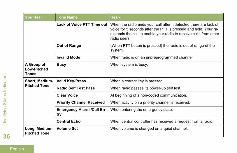
You Hear Tone Name Heard
Lack of Voice PTT Time out When the radio ends your call after it detected there are lack ofvoice for 5 seconds after the PTT is pressed and hold. Your ra-dio ends the call to enable your radio to receive calls from otherradio users.
Out of Range (When PTT button is pressed) the radio is out of range of thesystem.
Invalid Mode When radio is on an unpreprogrammed channel.
A Group ofLow-PitchedTones
Busy When system is busy.
Short, Medium-Pitched Tone
Valid Key-Press When a correct key is pressed.
Radio Self Test Pass When radio passes its power-up self test.
Clear Voice At beginning of a non-coded communication.
Priority Channel Received When activity on a priority channel is received.
Emergency Alarm /Call En-try
When entering the emergency state.
Central Echo When central controller has received a request from a radio.
Long, Medium-Pitched Tone
Volume Set When volume is changed on a quiet channel.
Iden
tifyi
ng S
tatu
s In
dica
tors
36
English
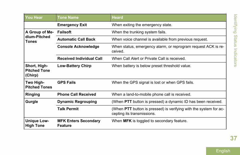
You Hear Tone Name Heard
Emergency Exit When exiting the emergency state.
A Group of Me-dium-PitchedTones
Failsoft When the trunking system fails.
Automatic Call Back When voice channel is available from previous request.
Console Acknowledge When status, emergency alarm, or reprogram request ACK is re-ceived.
Received Individual Call When Call Alert or Private Call is received.
Short, High-Pitched Tone(Chirp)
Low-Battery Chirp When battery is below preset threshold value.
Two High-Pitched Tones
GPS Fails When the GPS signal is lost or when GPS fails.
Ringing Phone Call Received When a land-to-mobile phone call is received.
Gurgle Dynamic Regrouping (When PTT button is pressed) a dynamic ID has been received.
Talk Permit (When PTT button is pressed) is verifying with the system for ac-cepting its transmissions.
Unique Low-High Tone
MFK Enters SecondaryFeature
When MFK is toggled to secondary feature.
Identifying Status Indicators
37
English
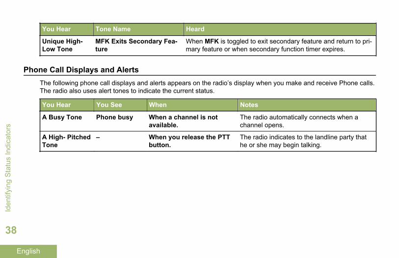
You Hear Tone Name Heard
Unique High-Low Tone
MFK Exits Secondary Fea-ture
When MFK is toggled to exit secondary feature and return to pri-mary feature or when secondary function timer expires.
Phone Call Displays and AlertsThe following phone call displays and alerts appears on the radio’s display when you make and receive Phone calls.The radio also uses alert tones to indicate the current status.
You Hear You See When Notes
A Busy Tone Phone busy When a channel is notavailable.
The radio automatically connects when achannel opens.
A High- PitchedTone
– When you release the PTTbutton.
The radio indicates to the landline party thathe or she may begin talking.
Iden
tifyi
ng S
tatu
s In
dica
tors
38
English
General Radio Operation
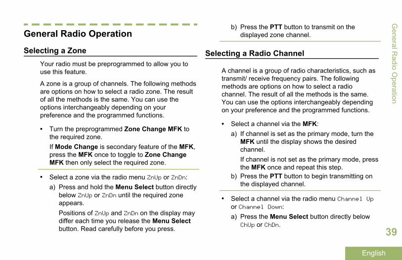
Selecting a ZoneYour radio must be preprogrammed to allow you touse this feature.
A zone is a group of channels. The following methodsare options on how to select a radio zone. The resultof all the methods is the same. You can use theoptions interchangeably depending on yourpreference and the programmed functions.
• Turn the preprogrammed Zone Change MFK tothe required zone.If Mode Change is secondary feature of the MFK,press the MFK once to toggle to Zone ChangeMFK then only select the required zone.
• Select a zone via the radio menu ZnUp or ZnDn:a) Press and hold the Menu Select button directly
below ZnUp or ZnDn until the required zoneappears.Positions of ZnUp and ZnDn on the display maydiffer each time you release the Menu Selectbutton. Read carefully before you press.
b) Press the PTT button to transmit on thedisplayed zone channel.
Selecting a Radio Channel
A channel is a group of radio characteristics, such astransmit/ receive frequency pairs. The followingmethods are options on how to select a radiochannel. The result of all the methods is the same.You can use the options interchangeably dependingon your preference and the programmed functions.
• Select a channel via the MFK:a) If channel is set as the primary mode, turn the
MFK until the display shows the desiredchannel.If channel is not set as the primary mode, pressthe MFK once and repeat this step.
b) Press the PTT button to begin transmitting onthe displayed channel.
• Select a channel via the radio menu Channel Upor Channel Down:a) Press the Menu Select button directly below
ChUp or ChDn.
General R
adio Operation
39
English
Positions of ChUp and ChDn on the display maydiffer each time you release the Menu Selectbutton. Read carefully before you press.
b) Press the PTT button to transmit on thedisplayed zone and channel.
Mode Select FeatureMode Select allows a long press to save the currentzone and channel of your radio to a programmablebutton, or a softkey; then once programmed, theshort-press of that button or softkey changes thetransmission to the saved zone and channel.
There are two methods to save the selected zone andchannel:
• Softkeys• Programmable buttons
Note:Your radio must be preprogrammed to allowyou to use this feature.
Saving a Zone and a Channel to a Softkey
Five softkeys are available for you to save thefrequently used zone and channel.
1 Toggle your zone and channel to the requiredzone and channel.
2 Press and hold the Menu Select button directlybelow one of the softkey (MS1 – MS5).
You hear a short, medium-pitched tone when thezone and channel is saved.
Note:To change the programmed zone andchannel, repeat this procedure.
Short press of the programmed softkeychanges your current transmission to the zoneand channel programmed in this softkey.
Saving a Zone and a Channel to a Button
You can save the frequent used zone and channel tothe programmable buttons.
1 Toggle your zone and channel to the requiredzone and channel.
2 Press and hold the button you desire to program.
You hear a short, medium-pitched tone when thezone and channel is saved.
Gen
eral
Rad
io O
pera
tion
40
English
Note:Repeat this procedure to change the zone andchannel of the programmed button.
Short press of the programmed buttonchanges your current transmission to the zoneand channel programmed in this button.
Receiving and Responding to a Radio CallOnce you have selected the required channel and/orzone, you can proceed to receive and respond tocalls.
The LED lights up solid red while the radio istransmitting. In conventional mode, the LED lights upsolid yellow when the radio is receiving atransmission. In trunking mode, there is no LEDindication when the radio receives a transmission.
If the radio is receiving a secure transmission, theLED blinks yellow.
Receiving and Responding to a Talkgroup Call
To receive a call from a group of users, your radiomust be configured as part of that talkgroup.
When you receive a talkgroup call (while on theHome screen) the radio triggers for your attention with
one of the following scenarios depending on thesystem your radio is configured:
• For ASTRO Conventional system, the LED lightsup solid yellow. The display shows the talkgroupalias or ID, and the caller alias or ID.
• For Trunking system, the display shows the calleralias or ID.
1 Hold the radio vertically 1 to 2 inches (2.5 to 5.0cm) from your mouth.
2 Press the PTT button to respond to the call.The LED lights up solid red.
3 Release the PTT button to listen.
Receiving and Responding to a Private Call (TrunkingOnly)
A Private Call is a call from an individual radio toanother individual radio.
The one-to-one call between the two radios are notheard by the others in the current talkgroup. Thecalling radio automatically verifies that the receivingradio is active on the system and can display thecaller ID.
General R
adio Operation
41
English
Note:With the inactivity timer enabled (optional),when there is no response from the receivingradio, the calling radio exits the call with MenuInactive Exit tone after the timer expires.
When you receive a Private Call, you hear two alerttones and the LED blinks green. The display showsCall received and the call received icon blinks.
1 Perform one of the following actions:
• Press the Menu Select button directly belowResp.
• Press the Call Response button within 20seconds after the call indicators begin.
If the caller alias is in the call list, the displayshows the caller alias during the call.
If the caller name is not in the call list, the displayshows the caller ID.
2 Press and hold the PTT button to talk. Release thePTT button to listen.
3 Press or the Call Response button to hang upand return to the Home screen.
You cannot initiate a Private Call.
Receiving and Responding to a Telephone Call(Trunking Only)
This feature allows you to receive calls similar tostandard phone calls from a landline phone.
Note:With the inactivity timer enabled (optional), ifthere is no response to the call after the timerexpires, your radio exits the call with MenuInactive Exit tone.
When you receive a Telephone Call, you hear atelephone-type ringing and the LED blinks green. Thedisplay shows Phone Call and the call received iconblinks.
1 Press the Call Response button within 20seconds after the call indicators begin.
2 Press and hold the PTT button to talk. Release thePTT button to listen.
3 Press the Call Response button to hang up andreturn to the Home screen.
You cannot initiate a Telephone Call.
Gen
eral
Rad
io O
pera
tion
42
English
Switching Between Repeater or DirectOperation Button
The Repeater Operation increases the radiocoverage area by connecting with other radiosthrough a repeater. The transmit and receivefrequencies are different.
The Direct or “talkaround operation” allows you tobypass the repeater and connect directly to anotherradio. The transmit and receive frequencies are thesame.
Perform one of the following actions:
• Press the preprogrammed Repeater/Directswitch to toggle between talkaround andrepeater modes.
• or to Dir and press the Menu Select buttondirectly below Dir.
The display shows Repeater mode if the radio iscurrently in Repeater mode.
The display shows Direct mode and the Talkaroundicon if the radio is currently in Direct mode (duringconventional operation only).
Monitor FeatureRadio users who switch from analog to digital radiosoften assume that the lack of static on a digitalchannel is an indication that the radio is not workingproperly. This is not the case.
Digital technology quiets the transmission byremoving the noise from the signal and allows onlythe clear voice or data information to be heard.
Use the Monitor feature to make sure a channel isclear before transmitting.
Monitoring a Channel
The following methods are options on how to monitora channel. The result of all the methods is the same.You can use the options interchangeably dependingon your preference and the programmed functions.
• Monitoring a Channel with Monitor button.a) Press the preprogrammed Monitor button.b) Adjust the Volume Control Knob if necessary.c) Press and hold the PTT button to transmit.
The LED lights up solid red.d) Release the PTT button to receive (listen).
General R
adio Operation
43
English
The Carrier Squelch indicator appears on thedisplay when you monitor a channel via thepreprogrammed Monitor button.
• Monitoring a Channel via the selected zonechannel.a) Select the desired zone and channel.b) Listen for a transmission.c) Adjust the Volume Control Knob if necessary.d) Press and hold the PTT button to transmit.
The LED lights up solid red.e) Release the PTT button to receive (listen).
Monitoring Conventional Mode
Your radio may be preprogrammed to receive Private-Line® (PL) calls.
1 Momentarily press the Monitor button to listen foractivity.The Carrier Squelch indicator appears on thedisplay.
2 Press and hold the Monitor button to setcontinuous monitor operation.The duration of the button press is programmable.
3 Press the Monitor button again, or the PTTbutton, to return to the original squelch setting.If you try to transmit on a receive-only channel,you hear an invalid tone until you release the PTTbutton.
Gen
eral
Rad
io O
pera
tion
44
English
Advanced Features
Advanced Call FeaturesSelective Call (ASTRO Conventional Only)
Receiving a Selective Call
When you receive a Selective Call, the radio initiatesfor your attention with one of the following indicationscenario:
• You hear two alert tones and the LED lights upsolid yellow to indicate the transmitting radio is stillsending signal. The call received icons blinks andthe display shows Call received.
• The LED blinks solid green once to indicate thetransmitting radio is pending to receive signal.
The speaker unmutes.
1 Hold the radio vertically 1 to 2 inches (2.5 to 5.0cm) from your mouth.
2 Press and hold the PTT button to talk. Release thePTT button to listen.
Responding to the Dynamic Regrouping Feature(Trunking Only)
This feature allows the dispatcher to temporarilyreassign selected radios to a particular channelwhere they can communicate with each other. Thisfeature is typically used during special operations andis enabled by a qualified radio technician.
You will not notice whether your radio has this featureenabled until a dynamic regrouping command is sentby the dispatcher.
Note:If you try to access a zone or channel that hasbeen reserved by the dispatcher as adynamically regrouped mode for other users,you hear an invalid tone.
When your radio is dynamically regrouped, itautomatically switches to the dynamically regroupedchannel. You hear a Gurgle tone and the displayshows the dynamically regrouped channel’s name.
Press the PTT button to talk. Release PTT buttonto listen.
When the dispatcher cancels dynamic regrouping, theradio automatically returns to the zone and channel
Advanced Features
45
English
that you were using before the radio was dynamicallyregrouped.Requesting a Reprogram (Trunking Only)
This feature allows you to notify the dispatcher whenyou want a new dynamic regrouping assignment.
Press the preprogrammed Reprogram Requestbutton to send reprogram request to thedispatcher.The display shows Reprgrm rqst and Pleasewait.
If you hear five beeps, the dispatcher hasacknowledged the reprogram request. The displayshows Ack received and the radio returns to theHome screen.
If the dispatcher does not acknowledge thereprogram request within six seconds, you hear alow-pitched alert tone and the display shows Noacknowledge. Try again or press to cancel and returnto the Home screen.
Classification of Regrouped Radios
The dispatcher can classify regrouped radios intoeither of two categories:
SelectEnabled
Select-enabled radios are free tochange to any available channel,including the dynamic-regroupingchannel, once the user has selectedthe dynamic-regrouping position.
SelectDisabled
Select-disabled radios cannot changechannels while dynamically regrouped.The dispatcher has forced the radio toremain on the dynamic-regroupingchannel.
The Scan or Private Call feature cannot be selectedwhile your radio is Select Disabled.
Scan ListsScan lists are created and assigned to individualchannels/ groups. Your radio scans for voice activityby cycling through the channel/group sequencespecified in the scan list for the current channel/group.
Your radio supports different types of Scan Lists:
• Trunking Priority Monitor Scan List• Conventional Scan List• Talkgroup Scan List
Adv
ance
d Fe
atur
es
46
English
Please refer to a qualified radio technician for themaximum number of Scan Lists can be programmedin your radio. These lists must be preprogrammed bya qualified radio technician.
Viewing a Scan List
Turn the MFK to view the members on the list.
Viewing and Changing the Priority Status
Perform one of the following actions:
• Press the Menu Select button directly belowSel one or more times to change the prioritystatus of the current displayed channel.
• Press the Select button one or more times totoggle between different status of the Scan Liststatus icon of the current displayed channel.
The radio shows one of following priority statusicons and scenarios:
• A Scan icon indicates that the current channelis in the scan list as a non-priority channel. TheLED lights up solid green.
• A Priority-Two Channel Scan icon indicatesthat the current channel is in the scan list as
the Priority-Two channel. The LED blinksgreen.
• A Priority-One Channel Scan icon indicatesthat the current channel is in the scan list asthe Priority-One channel. The LED rapidlyblinks green. You hear all traffic on the Priority-One channel, regardless of traffic on non-priority channels.
• No icon indicates that the current channel isdeleted from the scan list.
ScanThis feature allows you to monitor traffic on differentchannels by scanning a preprogrammed list ofchannels.
Turning Scan On or Off
Perform one of the following actions:
• Press the preprogrammed Scan button totoggle Scan On or Scan Off to initiate or stopscan.
• Press the Menu Select button directly belowScan.
Advanced Features
47
English
If the scan is enabled, the display shows Scan onand the scan status icon.
If the scan is disabled, the display shows ScanOff.
The radio returns to the Home screen.
Making a Dynamic Priority Change (Conventional ScanOnly)
While the radio is scanning, the dynamic prioritychange feature allows you to temporarily change anychannel in a scan list (except for the Priority-Onechannel) to the Priority-Two channel.
This change remains in effect until scan is turned off.Scan then reverts to the preprogrammed (original)setting.
Making a Dynamic Priority Change via thepreprogrammed Dynamic Priority button:a) When the radio locks onto the channel
designated as the new Priority-Two channel,press the preprogrammed Dynamic Prioritybutton.The radio continues scanning the remainingchannels in the list.
Deleting a Nuisance Channel
If a channel continually generates unwanted calls ornoise (termed a “nuisance” channel), you cantemporarily remove the unwanted channel from thescan list.
This capability does not apply to priority channels orthe designated transmit channel.
When the radio is locked onto the channel to bedeleted, perform one of the following actions:
• Press and hold the Menu Select button belowScan or preprogrammed Scan button to deletethe nuisance channel.
• Press the preprogrammed Nuisance Deletebutton.
• Press the Menu Select button directly belowNuis.
The radio continues scanning the remaining channelsin the list.
Restoring a Nuisance Channel
To restore the deleted nuisance channel, performone of the following actions:
Adv
ance
d Fe
atur
es
48
English
• Stop and restart a scan.• Mode change to another channel and back to
the original channel.• Turn off the radio and then turn it on again.
Nuisance mode delete can be disabled by thesystem administrator.
Call Alert PagingThis feature allows your radio to work like a pager.
The radio which you missed its call can send a CallAlert page to your radio. The sender also able toknow that your radio is active.
Note:This feature must be preprogrammed by aqualified radio technician.
Receiving a Call Alert Page
When you receive a Call Alert page, you hear fourrepeating alert tones and the LED blinks green. Thecall received icons blinks and the display shows Pagereceived.
Press any button to clear the Call Alert page.
You cannot send a Call Alert page.
Emergency OperationThe Emergency feature is used to indicate a criticalsituation.
If the Top (Orange) button is preprogrammed to sendan emergency signal, this signal overrides any othercommunication over the selected channel.
Your radio supports the following Emergency modes:
• Emergency Alarm• Emergency Call (Trunking Only)• Emergency Alarm with Emergency Call• Silent Emergency Alarm
Check with your dealer or system administrator formore information on the programming of this feature.
Only one of the Emergency modes above can beassigned to the preprogrammed Emergency button.
Note:To exit emergency at any time, press and holdthe preprogrammed Emergency button forabout a second. This timer is programmablefrom 0 – 6250 milliseconds by a qualifiedtechnician.
Advanced Features
49
English
The radio operates in the normal dispatchmanner while in Emergency Call, except ifenabled, it returns to one of the following:
Tactical/Non-Revert
The radio sendsemergency alarm and/ormake emergency call onthe current selectedchannel.
Non-Tactical/Revert forConventionalsystem
The radio reverts to thepreprogrammedemergency channel tosend alarm and/or makeemergency call.
Non-Tactical/Revert forTrunkingsystem
The radio reverts to thepreprogrammedemergency talkgroup tosend alarm and/or makeemergency call.
Sending an Emergency Alarm
This feature allows you to send a data transmission,which identifies the radio sending the emergency, tothe dispatcher.
Note:The default timer of Emergency button pressto activate Emergency is 50 milliseconds. Thistimer is programmable from 50 – 6200milliseconds by a qualified technician.
Press the preprogrammed Emergency button.
One of the following scenarios occurs:
• The display shows Emergency and the currentzone or channel. You hear a short medium-pitched tone and the LED blinks redmomentarily.
• The radio sounds a short low-pitched tone toindicate that the selected channel does notsupport emergency and rejects to launchemergency mode. The display shows Noemergency, if the selected channel does notsupport emergency.
When you receive the dispatcher’s acknowledgment,the display shows Ack received. Four tones sound,the alarm ends, and the radio exits the EmergencyAlarm mode.
If no acknowledgement is received, the display showsNo acknowledge. The alarm ends when the timer
Adv
ance
d Fe
atur
es
50
English
expires and the radio exits the Emergency Alarmmode.
Sending an Emergency Call (Trunking Only)
This feature gives your radio priority access to atalkgroup.
1 Press the preprogrammed Emergency button.One of the following scenarios occurs:
• The display shows Emergency on the currentzone and channel. You hear a short medium-pitched tone and the LED blinks redmomentarily.
• You hear the radio sounds a short low-pitchedtone to indicate the selected channel does notsupport emergency and rejects to launchemergency mode.
2 Hold the radio vertically 1 to 2 inches (2.5 to 5.0cm) from your mouth.
3 Press and hold the PTT button. Speak clearly intothe microphone.
4 Release the PTT button to end the transmissionand wait for a response from the dispatcher.
5 To exit Emergency Call, press and hold thepreprogrammed Emergency button for about asecond.
Sending an Emergency Alarm with Emergency Call
This feature gives your radio priority access on achannel for conventional system, and to a talkgroupfor trunking system.
1 Press the preprogrammed Emergency button.
If successful, the display shows Emergency on thecurrent zone and channel. You hear a short,medium-pitched tone and the LED blinks redmomentarily.
The radio exits Emergency Alarm and enters theEmergency Call state when one of the followingscenarios occur:
• You receive the dispatcher acknowledgment.The display shows Ack received.
• You receive no acknowledgement. The displayshows No acknowledge.
• You press the PTT button while in theEmergency Alarm mode.
Advanced Features
51
English
If unsuccessful, you hear the radio sounds a shortlow-pitched tone to indicate the selected channeldoes not support emergency and rejects to launchemergency mode.
2 Hold the radio vertically 1 to 2 inches (2.5 to 5.0cm) from your mouth.
3 Press and hold the PTT button. Speak clearly intothe microphone.
4 Release the PTT button to end the transmissionand wait for a response from the dispatcher.
5 To exit Emergency Call, press and hold thepreprogrammed Emergency button for about asecond.Turning off the radio also cancels the emergencystate.
Sending a Silent Emergency Alarm
This feature allows you to send an Emergency Alarmto the system without triggering any audio or visualindicators.
1 Press the preprogrammed Emergency button.
The display shows no changes, the LED does notlight up, and you hear no tones. The silentemergency state continues until you perform thenext step.
2 Perform one of the following actions:
• You press and hold the preprogrammedEmergency button for about a second to exitthe Silent Emergency Alarm mode.
• Press and release the PTT button to exit theSilent Emergency Alarm mode and enterregular dispatch or Emergency Call mode.
Change of Channels during Emergency
For ALL Emergency transmissions, when changingchannels:
• If the new channel is also preprogrammed forEmergency, you can change channels while inEmergency operation. The emergency alarm orcall continues on the new channel.
• If the new channel is not preprogrammed forEmergency, the display shows No emergency,and you hear an invalid tone until you exit theEmergency state or change to a channelpreprogrammed for Emergency.
Adv
ance
d Fe
atur
es
52
English
Emergency Keep-Alive Feature
This feature, when enabled, prevents the radio frombeing turned off via the MFK when the radio is in theEmergency state.
Note:The radio only exits the Emergency stateusing one of the ways mentioned in theprevious sections.
See Sending an Emergency Alarm on page50, Sending an Emergency Call (TrunkingOnly) on page 51, Sending an EmergencyAlarm with Emergency Call on page 51, or Sending a Silent Emergency Alarm on page52.
Automatic Registration Service (ARS)This feature provides an automated data applicationregistration for the radio. When you turn on the radio,the device automatically registers with the server.
Data applications within the fixed network candetermine the presence of a device on the systemand send data to the device.
The Automatic Registration Service for the radioconsists of two (2) modes:
• ARS Server Mode (default mode)• ARS Non-Server Mode
Note:The default ARS mode can be changed by aqualified radio technician using the radio’sprogramming software.
Selecting or Changing the ARS Mode
The following methods are options on how to selector change the ARS Mode. The result of all themethods is the same. You can use the optionsinterchangeably depending on your preference andthe programmed functions.
• Selecting or Changing the ARS mode via theMFK:a) Once the zone you want is displayed, turn the
preprogrammed MFK to the desired mode.
• Selecting or Changing the ARS mode via the radiomenu:a) or to Chan.
Advanced Features
53
English
b) Press the Menu Select button directly belowChan.The display shows the current channel name.
c) or to the required channel or mode.One of the following scenarios occur:
• In ARS Server Mode, the display shows thezone and ARS server channel.
• In ARS Non-Server Mode, the displayshows the zone and ARS non-serverchannel.
• If the channel or mode selected isunprogrammed, the display showsUnprogrammed. Repeat this step.
d) Press Sel to confirm the displayed channel.
Global Positioning System / GlobalNavigation Satellite System
The Global Navigation Satellite System (GNSS) in theradio uses information from the Global PositioningSystem (GPS) to determine the approximategeographical location of your radio. The geographicallocation is expressed as latitude and longitude orMilitary Grid Reference System (MGRS) format perrequest from customers.
Note:This feature is addressed as GPS across themanual as the naming convention of thebuttons and strings remain the same as thelegacy feature of GPS.
The availability and accuracy of this locationinformation (and the amount of time that it takes tocalculate it) varies depending on the environment inwhich you are using the GPS feature.
For example, GPS location fixes are difficult to obtainindoors, in covered locations, between high buildings,or in situations where you have not established aclear broad view of the sky.
Once GPS is enabled, the radio displays the GPSicon on the screen. The dispatcher can alwaysrequest the system to determine the real-time locationcoordinates of the radio.
GPS Operation
The GPS technology uses radio signals from earthorbiting satellites, to establish the locationcoordinates, maximizing your view of clearunobstructed sky is essential for optimumperformance.
Adv
ance
d Fe
atur
es
54
English
Where adequate signals from multiple satellites arenot available (usually because you cannot establish aview of a wide area of the sky), the GPS feature ofyour radio will not work. Such situations include butare not limited to:
• Underground locations• Inside of buildings, trains, or other covered
vehicles• Under any other metal or concrete roof or
structure• Between tall buildings or under dense tree-cover• In temperature extremes outside the operating
limits of your radio
Even where location information can be calculated insuch situations, it may take longer to do so, and yourlocation estimate may not be as accurate. Therefore,in any emergency situation, always report yourlocation to your dispatcher.
Keep in mind that the accuracy of the locationinformation and the time it takes to obtain it variesdepending upon circumstances, particularly the abilityto receive signals from an adequate number ofsatellites.
Note:Even where adequate signals from multiplesatellites are available, your GPS feature onlyprovides an approximate location, usuallywithin 10 meters from your actual location, butsometimes farther away.
The satellites used by the GPS feature are controlledby the U.S. government and are subject to changesimplemented in accordance with the Department ofDefense GPS user policy and the Federal RadioNavigation Plan. These changes may affect theperformance of the GPS feature on your radio.
GPS Performance Enhancement
Sometimes, the GPS feature may be unable tocomplete a location calculation successfully. You thensee a message indicating that your radio cannotconnect to enough visible satellites.
To maximize the ability of your radio to determine afix, take note of the following guidelines:
• For your initial fix, hold the radio in the faceposition.
• Stay in the open. The GPS feature works bestwhere there is nothing between your radio and alarge amount of open sky.
Advanced Features
55
English
Peer-Location on the Display (ASTRO Conventionalonly)
This feature is only available for radio-to-radio voicetransmissions, dispatch call and selective call inconventional ASTRO system. For radio-to-radiotransmission, in order to allow the radio to show peer-location, the voice should be directly sent from oneradio to another radio without passing through anyinfrastructure facility such as repeaters, phone orDVRS system. Both the transmitting radio andreceiving radio must be configured to enable them tosend and/or receive the GPS coordinates. You cancheck with your nearest qualified technician for moredetails.
Note:If the receiving radio is operating in a MixedMode channel, only if its voice transmission isvia conventional ASTRO system then it canreceive the location coordinates of its peers.
This feature is also operable in a Scan Active channelor Scan Talkback channel.
Upon receiving a voice transmission with GPScoordinates enabled on the receiving radio, thedisplay shows the coordinates available in full or inshort coordinates. There are two different formats
available. Refer to the following list for the detailsshown in the Peer-Location quick text. Consult youragent to pick the best format to configure to yourradio.
Full locationcoordinates
• PTT ID (This is optional.)• Longitude and latitude• Relative distance or
direction.
Short locationcoordinates
• PTT ID (This is optional.)• Longitude and latitude
Geofence (ASTRO 25 Trunking System)Geofence is a virtual perimeter based on the GPS todefine a geographical area on earth.
When the radio enters the predefined Geofence area,your radio receives the Dynamic Regroup commandfrom the system and immediately connects to aDynamic Regroup talkgroup. The radio display showsthe new selected Dynamic Regrouped talkgroup withgreen intelligent light for your attention.
Voice Announcement is also available to support thisfeature. Check with your nearest qualified technician
Adv
ance
d Fe
atur
es
56
English
on the requirements for this enhancement to work inGeofence.
Any new text messages received at Geofence shallhave its content displayed immediately on the radiodisplay.
Note:If the radio is set up in DVRS, only mobileradio is supported for this feature.
Entering the Geofence Area
The Voice Announcement and TMS display in thisfeature are optional. They must be configured toenable you to hear and see these indicators.
When the radio enters a Geofence area, the radioimmediately sends a message ACK back to thesystem.
The radio searches the current zone for the channelwith same talkgroup assigned as the DynamicTalkgroup and also with same system ID of currenttrunk system. Once matched, the radio display showsthe first matched and connected channel alias.
If there is no channel with matched Talkgroup ID andtrunk system ID, the radio display shows the channelalias of <DYNAMIC talkgroup>.
Once the radio is connected, you hear a dynamicregroup tone, the radio display shows <DYNAMICchannel> with temporary green color intelligentbacklight and you hear a Voice Announcement.
Note:When the radio loss the GPS signal the GPSicon blinks and the radio sounds two high-pitched tones repetitively to indicate GPS failsto operate. The radio display shows redintelligent light.
Note:If the first matched channel is not configuredwith Voice Announcement, no VoiceAnnouncement is played.
The system sends a message to your radio. Theradio display shows a direct text message contentwithout any user operation. This message indicatesyou are currently present in a Geofence area. ThisTMS remains open on the display until user pressesexit/home to exit this screen.
Note:If there is another incoming text messagebefore you exit the previous message, the
Advanced Features
57
English
message screen shall be refreshed to showthe latest message.
The following procedure guides you to exit the textmessage received.
Press the Menu Select button below Exit or toreturn to Home screen.
The other operations are the same as normaldynamic regroup command.
When the radio exits the Geofence area, your radioreverts to original channel or newly assignedtalkgroup. The radio display shows the new channeltogether with Voice Announcement to indicate thechanges. Voice Announcement of the new channelonly works if that channel is configured with VoiceAnnouncement.
Trunking System ControlsOperating in Failsoft System
The failsoft system ensures continuous radiocommunications during a trunked system failure. If atrunking system fails completely, the radio goes intofailsoft operation and automatically switches to itsfailsoft channel.
During failsoft operation, your radio transmits andreceives in conventional operation on apredetermined frequency. You hear a medium-pitched tone and the display shows Failsoft.
When the trunking system returns to normaloperation, your radio automatically leaves failsoftoperation and returns to trunked operation.
To continue, in Failsoft, to communicate with othertalkgroups, refer to the following procedure.
1 Rotate the Mode Knob to change to a differentrepeater frequency.
2 Press the PTT button to talk, and release thebutton to listen.
Out-of-Range Radio
When your radio goes out of the range of the system,it can no longer lock onto a control channel.
You hear a low-pitched tone and/or the display showsthe currently selected zone/channel combination andOut of range. Your radio remains in this out-of-range condition until it locks onto a control channel, itlocks onto a failsoft channel, or it is turned off.
Adv
ance
d Fe
atur
es
58
English
Site Trunking Feature
If the zone controller loses communication with anysite, that site reverts to site trunking.
The display shows the currently selected zone/channel combination and Site trunking.
Note:When this occurs, you can communicate onlywith other radios within your trunking site.
Locking and Unlocking a Site
This feature allows your radio to lock onto a specificsite and not roam among wide-area talkgroup sites.This feature should be used with caution, since itinhibits roaming to another site in a wide-areasystem.
You can toggle the lock state between locked andunlocked by pressing the preprogrammed Site Lock/Unlock button.
Follow the following procedure to lock and unlock asite via the radio menu.
1 Press the Menu Select button directly belowSite.
2 Perform one of the following actions:
• To lock the site, press the Menu Select buttondirectly below Lock. The display shows Sitelocked.
• To unlock the site, press the Menu Selectbutton directly below Unlk. The display showsSite unlocked.
The radio saves the new site lock state and returns tothe Home screen.
Site Display and Search Button
The Site Display and Site Search button allows youto view the name of the current site or force yourradio to change to a new one.
Viewing the Current Site
Perform one of the following actions:
• Press the preprogrammed Site Displ/Srchbutton.
• Press the Menu Select button directly belowRSSI.
Advanced Features
59
English
The display shows momentary the name of thecurrent site and its corresponding received signalstrength indicator (RSSI).Changing the Current Site
Perform one of the following actions:
• Press and hold down the preprogrammed SiteDispl/Srch button.
• Press and hold down the Menu Select buttondirectly below RSSI.
You hear a tone and the display showsmomentary Scanning site.
When the radio finds a new site, it returns to theHome screen.
Over-the-Air Programming (POP 25, ASTRO25, ASTRO Conventional)
This feature enables configuration data and firmwareto be upgraded to your radio over-the-air. Full use ofthe radio is retained during the data transfer withoutinterrupting communication. For ASTRO 25 andASTRO Conventional, the upgrade pauses to givepriorities to voice call, and continues after the voice
call ended. For Wi-Fi®, the upgrade process runsconcurrently with voice calls.
Once a configuration upgrade is downloaded to yourradio, you can install new changes immediately ordelay changes to be installed on the radio when it isbeing powered up.
Note:This feature must be preprogrammed by aqualified radio technician. Check with yourdealer or system administrator for moreinformation.
Responding to the Notification of Upgrade
1 The display shows Upgrade? and two short,medium- pitched tones sounds every 30 secondsuntil the user makes a choice of accepting,delaying, or rejecting the request
2 Perform one of the following actions:
• Press the Menu Select button below Acpt toaccept the request to upgrade immediately.
• Press the Menu Select button below Dlay todelay the request to upgrade.A
dvan
ced
Feat
ures
60
English
• Press the Menu Select button below Rej toreject the request to upgrade.
One of the following scenarios occurs:
• If you choose to accept, the display showsProgramming Dont power off to indicate theupgrade is about to begin. The radio resets toinstall the upgrade. In the case of configurationdata upgrade, this process only takes a fewseconds. In the case of firmware upgrade, theinstallation takes several minutes.
Note:The radio cannot be used while theupgrade is being installed. Therefore, makesure to only accept the upgrade at aconvenient time when immediate radio useis not required.
• If you choose to delay, a configuration dataupgrade is installed automatically at the nextpower up. However, in the case of a firmwareupgrade, the radio prompts Upgrade? again at thenext power up.
• If you choose to reject, the display shows UpgAborted. The radio continues to function with thecurrent configuration until it gets reprogrammed.
Note:If your radio has problems upgrading over-the-air, consult a qualified technician for details.
Voice AnnouncementThis feature enables the radio to audibly indicate thecurrent feature mode, zone or channel the user hasjust assigned. This audio indicator can be customizedper customer requirements. This is typically usefulwhen the user is in a difficult condition to read thecontent shown on the display.
Each voice announcement is within a limit of threeseconds maximum. The sum duration of all differentvoice announcements in a radio shall be no morethan 1000 seconds.
Note:This feature must be preprogrammed by aqualified radio technician.
Check with your agent if Voice Announcementis available for the feature you need.
The two options of priority for the VoiceAnnouncement available are:
Advanced Features
61
English
High Enables the voice of the feature to announceeven when the radio is receiving calls.
Low Disables the voice of the feature fromannouncing when the radio is receiving calls.
You hear a voice announcement when the featuresbelow are preprogrammed in the radio.
• The radio powers up. The radio announces thecurrent zone and channel it is transmitting.
• Press the preprogrammed voice announcementbutton (which specifically programmed to playbackthe current zone and channel). The radioannounces the current zone and channel it istransmitting.
Note:Pressing this preprogrammed playbackbutton enables the voice feature toannounce in High priority.
All the three programmable buttons at theside of the radio support this feature.
• Change to a new zone. The radio announces thecurrent zone and channel it is transmitting.
• Change to a new channel remaining within thecurrent zone. The radio announces the currentchannel.
• Press either the Menu Select button orpreprogrammed button of the radio to launch orterminate Scan, PL Disabled, Talkaround/Direct orTransmit Inhibit. The radio announces thecorresponding feature activation or deactivation.
UtilitiesSelecting the Power Level
Note:This feature must be preprogrammed by aqualified radio technician.
This feature enables you to reduce the transmitpower level for specific case that requires a lowerpower level. You can select the power level at whichyour radio transmits. The radio always turns on to thedefault setting. These reduced transmit power levelsettings do not affect the receiving performance ofyour radio, nor diminish the overall quality of theaudio and data functionality of the radio given thefollowing conditions.A
dvan
ced
Feat
ures
62
English
Power level Low enables a shorter transmittingdistance and to conserve power. Power level Highenables a longer transmitting distance.
The following methods are options on how to selectthe power level. The result of all the methods is thesame. You can use the options interchangeablydepending on your preference and the programmedfunctions.
• Selecting the Power Level via the TransmitPower Level switch:a) Use the preprogrammed Transmit Power
Level switch to toggle the power level betweenlow and high power.
• Selecting the Power Level via the radio menu:a) Press the Menu Select button directly below
Pwr.
The display shows Low power and the low powericon or the display shows High power and the highpower icon.
Enabling and Disabling the Radio Alias
This feature allows you to display or hide the radioalias (name).
Press the Menu Select button directly belowMyID.
The display shows momentary Radio ID off, andthe radio alias disappears from the Home screen orthe display shows momentary Radio ID on, and theradio alias appears on the Home screen.
Controlling the Display Backlight
You can enable or disable the radio’s displaybacklight as needed, if poor light conditions make thedisplay or keypad difficult to read.
Depending on how your radio is preprogrammed, youcan also maintain a minimum backlight level on theradio's front display.
Note:The backlight setting also affects the MenuSelect buttons backlighting accordingly.
The backlight remains on for apreprogrammed time before it automaticallyturns off completely or returns to the minimumbacklight level.
Perform one of the following actions:
Advanced Features
63
English
• To toggle the backlight on or off, press thepreprogrammed Light/Flip button.
• To turn the backlight on, press either the MenuSelect buttons or any programmable radiocontrols or buttons.
Locking and Unlocking the Controls
You can lock your radio programmable buttons andMFK to avoid inadvertent entry. Check with yourdealer or qualified technician for best selection to suityour usage.
1 Toggle the preprogrammed Keypad/Control Lockbutton to on.The display shows Kypd/Ctrl Lock.
2 Toggle again to unlock the controls.
Turning the Controls and Buttons Tones On or Off
You can enable and disable the tones of Navigationbuttons and controls if needed.
• Turning the tones on or off via the preprogrammedMute button:a) To turn the tones off or on, press the
preprogrammed Mute button.
• Turning the tones on or off via the radio menu:a) Press the Menu Select button directly below
Mute.The display shows momentary Tones off,indicating that the tones are disabled or thedisplay shows momentary Tones on, and youhear a short tone indicating that the tones areenabled.
Turning Voice Mute On or Off
You can enable and disable voice transmission, ifneeded.
• Turning Voice Mute off or on via thepreprogrammed Voice Mute button:a) To turn the feature off or on, press the
preprogrammed Voice Mute button.
• Turning Voice Mute on or off via the radio menu:a) Press the Menu Select button directly below
VMut.
The display shows momentary Voice mute off, andyou hear a short tone, indicating that the feature isdisabled or the display shows momentary Voice
Adv
ance
d Fe
atur
es
64
English
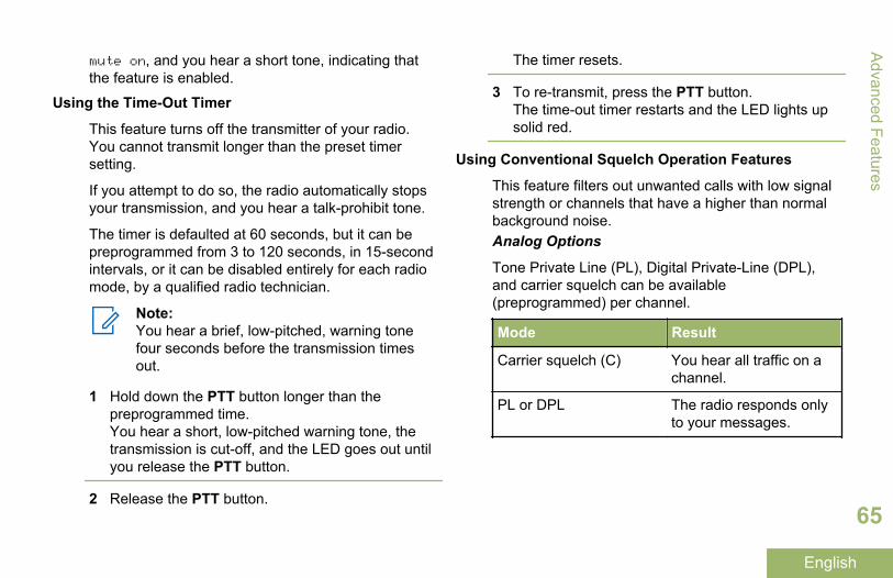
mute on, and you hear a short tone, indicating thatthe feature is enabled.
Using the Time-Out Timer
This feature turns off the transmitter of your radio.You cannot transmit longer than the preset timersetting.
If you attempt to do so, the radio automatically stopsyour transmission, and you hear a talk-prohibit tone.
The timer is defaulted at 60 seconds, but it can bepreprogrammed from 3 to 120 seconds, in 15-secondintervals, or it can be disabled entirely for each radiomode, by a qualified radio technician.
Note:You hear a brief, low-pitched, warning tonefour seconds before the transmission timesout.
1 Hold down the PTT button longer than thepreprogrammed time.You hear a short, low-pitched warning tone, thetransmission is cut-off, and the LED goes out untilyou release the PTT button.
2 Release the PTT button.
The timer resets.
3 To re-transmit, press the PTT button.The time-out timer restarts and the LED lights upsolid red.
Using Conventional Squelch Operation Features
This feature filters out unwanted calls with low signalstrength or channels that have a higher than normalbackground noise.Analog Options
Tone Private Line (PL), Digital Private-Line (DPL),and carrier squelch can be available(preprogrammed) per channel.
Mode Result
Carrier squelch (C) You hear all traffic on achannel.
PL or DPL The radio responds onlyto your messages.
Advanced Features
65
English
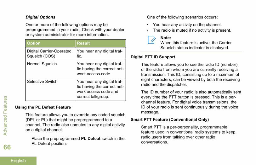
Digital Options
One or more of the following options may bepreprogrammed in your radio. Check with your dealeror system administrator for more information.
Option Result
Digital Carrier-OperatedSquelch (COS)
You hear any digital traf-fic.
Normal Squelch You hear any digital traf-fic having the correct net-work access code.
Selective Switch You hear any digital traf-fic having the correct net-work access code andcorrect talkgroup.
Using the PL Defeat Feature
This feature allows you to override any coded squelch(DPL or PL) that might be preprogrammed to achannel. The radio also unmutes to any digital activityon a digital channel.
Place the preprogrammed PL Defeat switch in thePL Defeat position.
One of the following scenarios occurs:
• You hear any activity on the channel.• The radio is muted if no activity is present.
Note:When this feature is active, the CarrierSquelch status indicator is displayed.
Digital PTT ID Support
This feature allows you to see the radio ID (number)of the radio from whom you are currently receiving atransmission. This ID, consisting up to a maximum ofeight characters, can be viewed by both the receivingradio and the dispatcher.
The ID number of your radio is also automatically sentevery time the PTT button is pressed. This is a per-channel feature. For digital voice transmissions, theID of your radio is sent continuously during the voicemessage.
Smart PTT Feature (Conventional Only)
Smart PTT is a per-personality, programmablefeature used in conventional radio systems to keepradio users from talking over other radioconversations.
Adv
ance
d Fe
atur
es
66
English
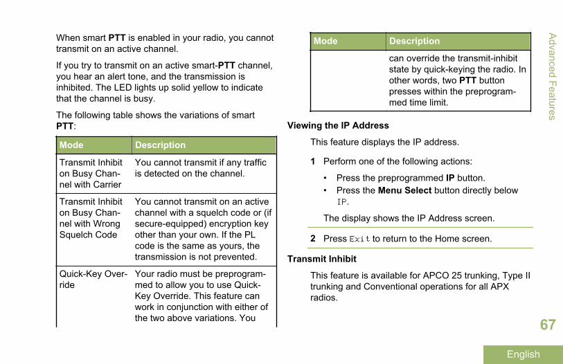
When smart PTT is enabled in your radio, you cannottransmit on an active channel.
If you try to transmit on an active smart-PTT channel,you hear an alert tone, and the transmission isinhibited. The LED lights up solid yellow to indicatethat the channel is busy.
The following table shows the variations of smartPTT:
Mode Description
Transmit Inhibiton Busy Chan-nel with Carrier
You cannot transmit if any trafficis detected on the channel.
Transmit Inhibiton Busy Chan-nel with WrongSquelch Code
You cannot transmit on an activechannel with a squelch code or (ifsecure-equipped) encryption keyother than your own. If the PLcode is the same as yours, thetransmission is not prevented.
Quick-Key Over-ride
Your radio must be preprogram-med to allow you to use Quick-Key Override. This feature canwork in conjunction with either ofthe two above variations. You
Mode Description
can override the transmit-inhibitstate by quick-keying the radio. Inother words, two PTT buttonpresses within the preprogram-med time limit.
Viewing the IP Address
This feature displays the IP address.
1 Perform one of the following actions:
• Press the preprogrammed IP button.• Press the Menu Select button directly below
IP.
The display shows the IP Address screen.
2 Press Exit to return to the Home screen.
Transmit Inhibit
This feature is available for APCO 25 trunking, Type IItrunking and Conventional operations for all APXradios.
Advanced Features
67
English
When Transmit Inhibit feature is enabled, the radiostops all transmission including voice and data. Theradio could receive messages but not replying theacknowledgement request of the received message.
User could physically control the transmission of theradio especially during operation in hazardousenvironments with this feature. An environment isconsidered hazardous when the power emitted by theradio power amplifier could initiate an explosion orother dangerous reactions.
When the Transmit Inhibit feature is disabled, theradio functions according to its normal operations.
The radio sounds alert tone when user enters or exitsthis feature and also when PTT is pressed.
Note:Acknowledgement of any messages requiredfrom the radio is not transmitted if the TransmitInhibition is enabled.
Enabling Transmit Inhibition
Press the Transmit Inhibit programmable button.
Note:If the user has disabled TX Inhibit via themenu and then moves the switch to the
position where TX Inhibit is enabled, thenew value overwrites the menu value.
The display shows Tx inhibit on. You hear asequence of short, low‐high tones to indicatetransmission is inhibited.
Pressing PTT triggers the radio sounds a constantshort, low‐pitched tone (reject tone).
Note:The status of the Transmit Inhibit does notchange after the radio powers up.
Disabling Transmit Inhibition
Press the Transmit Inhibit programmable button.
Note:If the user has disabled TX Inhibit via thesoftkey and then moves the switch to theposition where TX Inhibit is enabled, thenew value overwrites the menu value.
The display shows Tx inhibit off. You hear asequence of short, high‐low tone (Transmit InhibitOff tone) to indicate transmission is back to normaloperation.
Adv
ance
d Fe
atur
es
68
English
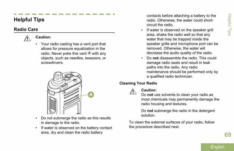
Helpful Tips
Radio CareCaution:
• Your radio casting has a vent port thatallows for pressure equalization in theradio. Never poke this vent with anyobjects, such as needles, tweezers, orscrewdrivers.
A
• Do not submerge the radio as this resultsin damage to the radio.
• If water is observed on the battery contactarea, dry and clean the radio battery
contacts before attaching a battery to theradio. Otherwise, the water could short-circuit the radio.
• If water is observed on the speaker grillarea, shake the radio well so that anywater that may be trapped inside thespeaker grille and microphone port can beremoved. Otherwise, the water willdecrease the audio quality of the radio.
• Do not disassemble the radio. This coulddamage radio seals and result in leakpaths into the radio. Any radiomaintenance should be performed only bya qualified radio technician.
Cleaning Your Radio
Caution:Do not use solvents to clean your radio asmost chemicals may permanently damage theradio housing and textures.
Do not submerge the radio in the detergentsolution.
To clean the external surfaces of your radio, followthe procedure described next.
Helpful Tips
69
English
1 Combine one teaspoon of mild dishwashingdetergent to one gallon of water (0.5% solution).
2 Apply the solution sparingly with a stiff, non-metallic, shortbristled brush, making sure excessdetergent does not get entrapped near theconnectors, controls or crevices. Dry the radiothoroughly with a soft, lint-free cloth.
3 Clean battery contacts with a lint-free cloth toremove dirt or grease.
Proper Ways to Handle the Radio
• Do not pound, drop, or throw the radiounnecessarily. Never carry the radio by theantenna.
• Avoid subjecting the radio to an excess of liquids.• Do not submerge the radio.• Avoid subjecting the radio to corrosives, solvents
or chemicals.• Do not disassemble the radio.• Caution:
Do not use the radio without an accessoryconnector or a dust cover in place ascontamination can build up on the contacts.
Radio Service and Repair
Proper repair and maintenance procedures willassure efficient operation and long life for thisproduct. A Motorola maintenance agreement willprovide expert service to keep this and all othercommunication equipment in perfect operatingcondition. A nationwide service organization isprovided by Motorola to support maintenanceservices. Through its maintenance and installationprogram, Motorola makes available the finest serviceto those desiring reliable, continuous communicationson a contract basis. For a contract service agreement,please contact your nearest Motorola service or salesrepresentative, or an authorized Motorola dealer.
Battery CareBattery Charge Status
Your radio can indicate the battery’s charge statusthrough:
• the LED and sounds.• the fuel gauge icon on the display.
LED and Sounds
When your battery is low:
Hel
pful
Tip
s
70
English
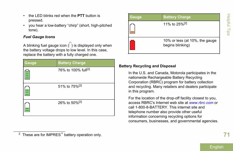
• the LED blinks red when the PTT button ispressed.
• you hear a low-battery “chirp” (short, high-pitchedtone).
Fuel Gauge Icons
A blinking fuel gauge icon ( ) is displayed only whenthe battery voltage drops to low level. In this case,replace the battery with a fully charged one.
Gauge Battery Charge
76% to 100% full[2]
51% to 75%[2]
26% to 50%[2]
Gauge Battery Charge
11% to 25%[2]
10% or less (at 10%, the gaugebegins blinking)
Battery Recycling and Disposal
In the U.S. and Canada, Motorola participates in thenationwide Rechargeable Battery RecyclingCorporation (RBRC) program for battery collectionand recycling. Many retailers and dealers participatein this program.
For the location of the drop-off facility closest to you,access RBRC's Internet web site at www.rbrc.com orcall 1-800-8-BATTERY. This internet site andtelephone number also provide other usefulinformation concerning recycling options forconsumers, businesses, and governmental agencies.
2 These are for IMPRES™ battery operation only.
Helpful Tips
71
English
AccessoriesThe accessory link below is for APX radios. Not allaccessories are FCC certified to operate with all APXmodels and/or bandsplits. Please refer to the specificAPX radio price pages for a list of FCC certifiedaccessories or contact your sales representative foraccessory compatibility.
http://www.motorolasolutions.com/APX
Note:Only the following programming cables arecompatible with the radios.
• APX DMR Port Programming Cable(PMKN4012B)
• Test and Alignment Programming Cable(PMKN4013C)
Acc
esso
ries
72
English
Maritime Radio Use in the VHFFrequency Range
Special Channel AssignmentsEmergency Channel
If you are in imminent and grave danger at sea andrequire emergency assistance, use VHF Channel 16to send a distress call to nearby vessels and theUnited States Coast Guard. Transmit the followinginformation, in this order:
1 “MAYDAY, MAYDAY, MAYDAY.”2 “THIS IS _____________________, CALL SIGN
__________.” State the name of the vessel indistress 3 times, followed by the call sign or otheridentification of the vessel, stated 3 times.
3 Repeat “MAYDAY” and the name of the vessel.4 “WE ARE LOCATED AT
_______________________.” State the positionof the vessel in distress, using any information thatwill help responders to locate you, e.g.:
• latitude and longitude• bearing (state whether you are using true or
magnetic north)
• distance to a well-known landmark• vessel course, speed or destination
5 State the nature of the distress.6 Specify what kind of assistance you need.7 State the number of persons on board and the
number needing medical attention, if any.8 Mention any other information that would be
helpful to responders, such as type of vessel,vessel length and/or tonnage, hull color, etc.
9 “OVER.”10 Wait for a response.11 If you do not receive an immediate response,
remain by the radio and repeat the transmission atintervals until you receive a response. Beprepared to follow any instructions given to you.
Non-Commercial Call Channel
For non-commercial transmissions, such as fishingreports, rendezvous arrangements, repair scheduling,or berthing information, use VHF Channel 9.
Operating Frequency RequirementsA radio designated for shipboard use must complywith Federal Communications Commission Rule Part80 as follows:
Maritim
e Radio U
se in the VH
F Frequency Range
73
English
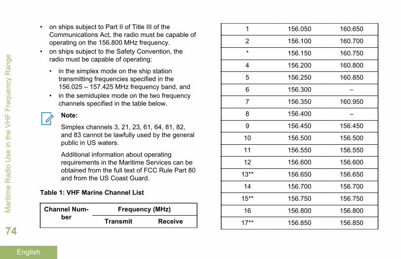
• on ships subject to Part II of Title III of theCommunications Act, the radio must be capable ofoperating on the 156.800 MHz frequency.
• on ships subject to the Safety Convention, theradio must be capable of operating:
• in the simplex mode on the ship stationtransmitting frequencies specified in the156.025 – 157.425 MHz frequency band, and
• in the semiduplex mode on the two frequencychannels specified in the table below.
Note:
Simplex channels 3, 21, 23, 61, 64, 81, 82,and 83 cannot be lawfully used by the generalpublic in US waters.
Additional information about operatingrequirements in the Maritime Services can beobtained from the full text of FCC Rule Part 80and from the US Coast Guard.
Table 1: VHF Marine Channel List
Channel Num-ber
Frequency (MHz)
Transmit Receive
1 156.050 160.650
2 156.100 160.700
* 156.150 160.750
4 156.200 160.800
5 156.250 160.850
6 156.300 –
7 156.350 160.950
8 156.400 –
9 156.450 156.450
10 156.500 156.500
11 156.550 156.550
12 156.600 156.600
13** 156.650 156.650
14 156.700 156.700
15** 156.750 156.750
16 156.800 156.800
17** 156.850 156.850
Mar
itim
e R
adio
Use
in th
e V
HF
Freq
uenc
y R
ange
74
English
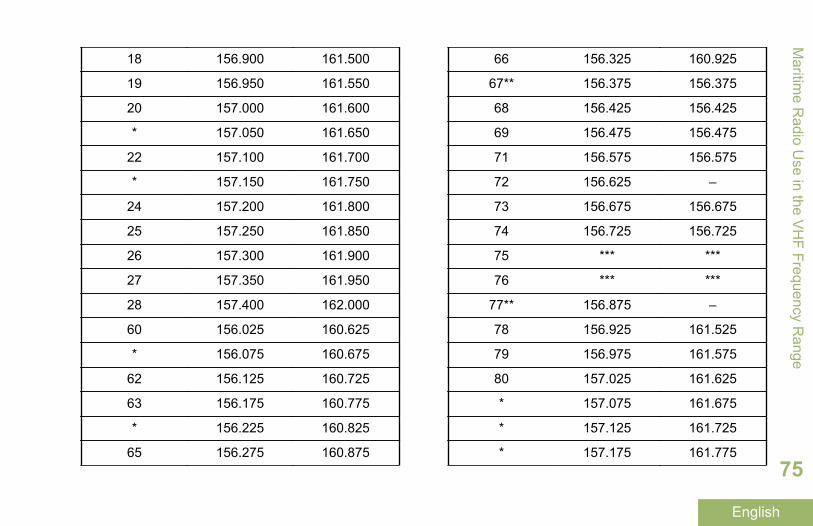
18 156.900 161.500
19 156.950 161.550
20 157.000 161.600
* 157.050 161.650
22 157.100 161.700
* 157.150 161.750
24 157.200 161.800
25 157.250 161.850
26 157.300 161.900
27 157.350 161.950
28 157.400 162.000
60 156.025 160.625
* 156.075 160.675
62 156.125 160.725
63 156.175 160.775
* 156.225 160.825
65 156.275 160.875
66 156.325 160.925
67** 156.375 156.375
68 156.425 156.425
69 156.475 156.475
71 156.575 156.575
72 156.625 –
73 156.675 156.675
74 156.725 156.725
75 *** ***
76 *** ***
77** 156.875 –
78 156.925 161.525
79 156.975 161.575
80 157.025 161.625
* 157.075 161.675
* 157.125 161.725
* 157.175 161.775
Maritim
e Radio U
se in the VH
F Frequency Range
75
English
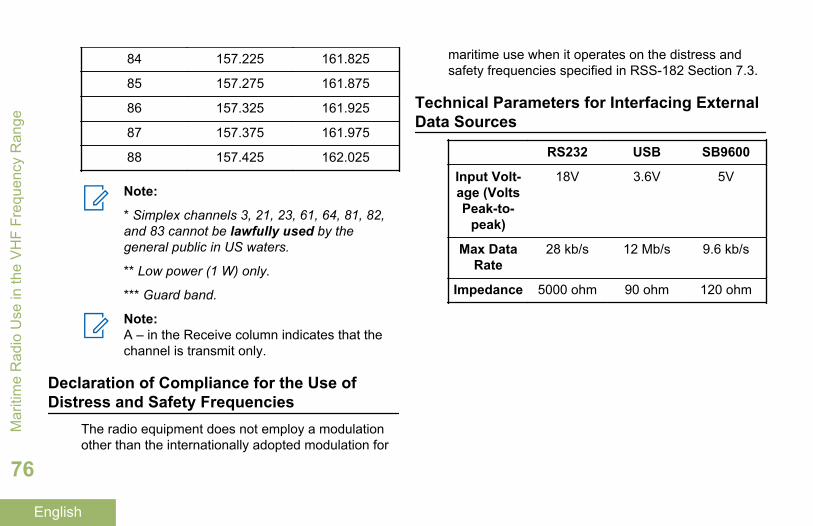
84 157.225 161.825
85 157.275 161.875
86 157.325 161.925
87 157.375 161.975
88 157.425 162.025
Note:
* Simplex channels 3, 21, 23, 61, 64, 81, 82,and 83 cannot be lawfully used by thegeneral public in US waters.
** Low power (1 W) only.
*** Guard band.
Note:A – in the Receive column indicates that thechannel is transmit only.
Declaration of Compliance for the Use ofDistress and Safety Frequencies
The radio equipment does not employ a modulationother than the internationally adopted modulation for
maritime use when it operates on the distress andsafety frequencies specified in RSS-182 Section 7.3.
Technical Parameters for Interfacing ExternalData Sources
RS232 USB SB9600
Input Volt-age (VoltsPeak-to-
peak)
18V 3.6V 5V
Max DataRate
28 kb/s 12 Mb/s 9.6 kb/s
Impedance 5000 ohm 90 ohm 120 ohm
Mar
itim
e R
adio
Use
in th
e V
HF
Freq
uenc
y R
ange
76
English
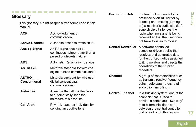
GlossaryThis glossary is a list of specialized terms used in thismanual.
ACK Acknowledgment ofcommunication.
Active Channel A channel that has traffic on it.
Analog Signal An RF signal that has acontinuous nature rather than apulsed or discrete nature.
ARS Automatic Registration Service
ASTRO 25 Motorola standard for wirelessdigital trunked communications.
ASTROConventional
Motorola standard for wirelessdigital conventionalcommunications.
Autoscan A feature that allows the radioto automatically scan themembers of a scan list.
Call Alert Privately page an individual bysending an audible tone.
Carrier Squelch Feature that responds to thepresence of an RF carrier byopening or unmuting (turningon) a receiver’s audio circuit. Asquelch circuit silences theradio when no signal is beingreceived so that the user doesnot have to listen to “noise”.
Central Controller A software-controlled,computer-driven device thatreceives and generates datafor the trunked radios assignedto it. It monitors and directs theoperations of the trunkedrepeaters.
Channel A group of characteristics suchas transmit/ receive frequencypairs, radio parameters, andencryption encoding.
Control Channel In a trunking system, one of thechannels that is used toprovide a continuous, two-way/data communications pathbetween the central controllerand all radios on the system.
Glossary
77
English
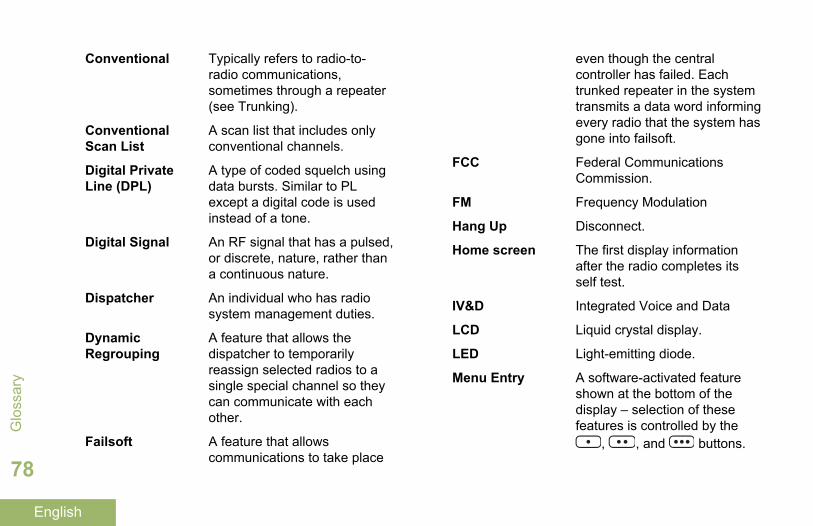
Conventional Typically refers to radio-to-radio communications,sometimes through a repeater(see Trunking).
ConventionalScan List
A scan list that includes onlyconventional channels.
Digital PrivateLine (DPL)
A type of coded squelch usingdata bursts. Similar to PLexcept a digital code is usedinstead of a tone.
Digital Signal An RF signal that has a pulsed,or discrete, nature, rather thana continuous nature.
Dispatcher An individual who has radiosystem management duties.
DynamicRegrouping
A feature that allows thedispatcher to temporarilyreassign selected radios to asingle special channel so theycan communicate with eachother.
Failsoft A feature that allowscommunications to take place
even though the centralcontroller has failed. Eachtrunked repeater in the systemtransmits a data word informingevery radio that the system hasgone into failsoft.
FCC Federal CommunicationsCommission.
FM Frequency Modulation
Hang Up Disconnect.
Home screen The first display informationafter the radio completes itsself test.
IV&D Integrated Voice and Data
LCD Liquid crystal display.
LED Light-emitting diode.
Menu Entry A software-activated featureshown at the bottom of thedisplay – selection of thesefeatures is controlled by the
, , and buttons.
Glo
ssar
y
78
English
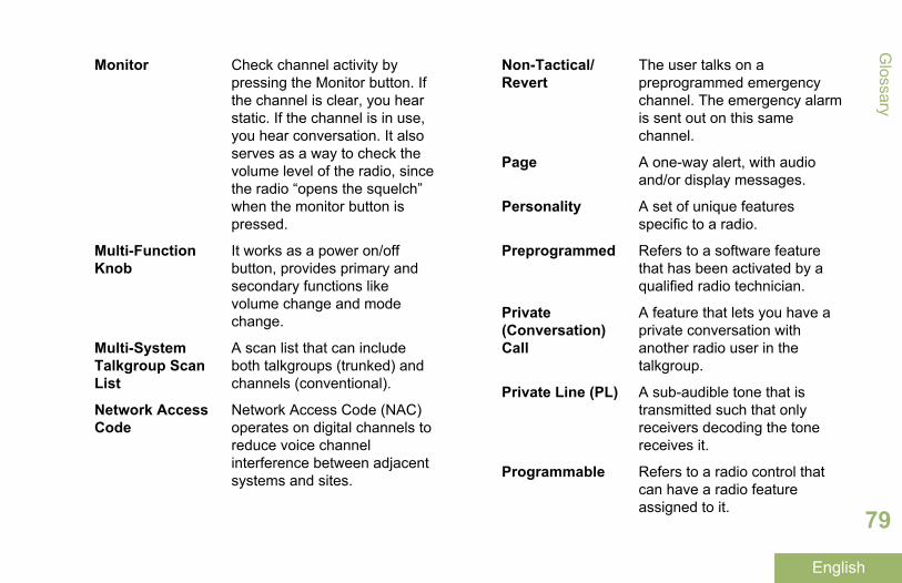
Monitor Check channel activity bypressing the Monitor button. Ifthe channel is clear, you hearstatic. If the channel is in use,you hear conversation. It alsoserves as a way to check thevolume level of the radio, sincethe radio “opens the squelch”when the monitor button ispressed.
Multi-FunctionKnob
It works as a power on/offbutton, provides primary andsecondary functions likevolume change and modechange.
Multi-SystemTalkgroup ScanList
A scan list that can includeboth talkgroups (trunked) andchannels (conventional).
Network AccessCode
Network Access Code (NAC)operates on digital channels toreduce voice channelinterference between adjacentsystems and sites.
Non-Tactical/Revert
The user talks on apreprogrammed emergencychannel. The emergency alarmis sent out on this samechannel.
Page A one-way alert, with audioand/or display messages.
Personality A set of unique featuresspecific to a radio.
Preprogrammed Refers to a software featurethat has been activated by aqualified radio technician.
Private(Conversation)Call
A feature that lets you have aprivate conversation withanother radio user in thetalkgroup.
Private Line (PL) A sub-audible tone that istransmitted such that onlyreceivers decoding the tonereceives it.
Programmable Refers to a radio control thatcan have a radio featureassigned to it.
Glossary
79
English
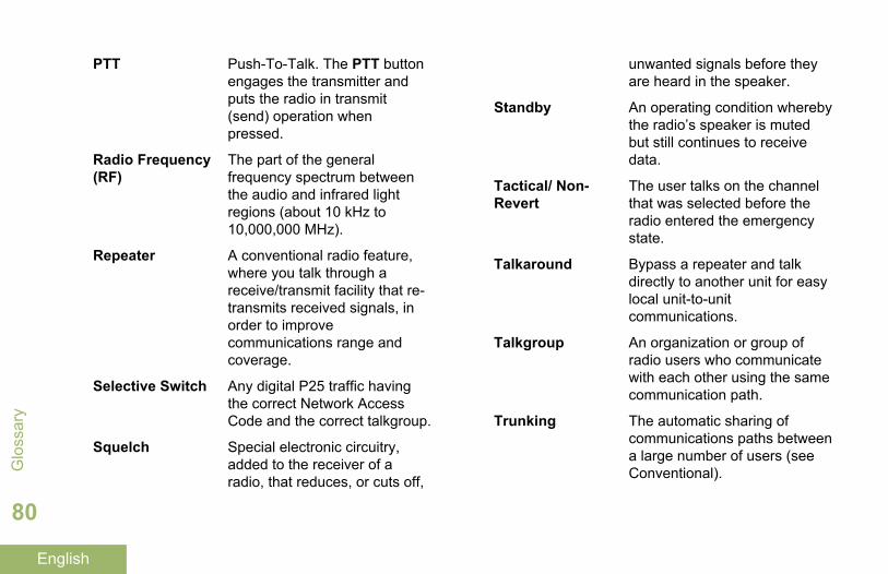
PTT Push-To-Talk. The PTT buttonengages the transmitter andputs the radio in transmit(send) operation whenpressed.
Radio Frequency(RF)
The part of the generalfrequency spectrum betweenthe audio and infrared lightregions (about 10 kHz to10,000,000 MHz).
Repeater A conventional radio feature,where you talk through areceive/transmit facility that re-transmits received signals, inorder to improvecommunications range andcoverage.
Selective Switch Any digital P25 traffic havingthe correct Network AccessCode and the correct talkgroup.
Squelch Special electronic circuitry,added to the receiver of aradio, that reduces, or cuts off,
unwanted signals before theyare heard in the speaker.
Standby An operating condition wherebythe radio’s speaker is mutedbut still continues to receivedata.
Tactical/ Non-Revert
The user talks on the channelthat was selected before theradio entered the emergencystate.
Talkaround Bypass a repeater and talkdirectly to another unit for easylocal unit-to-unitcommunications.
Talkgroup An organization or group ofradio users who communicatewith each other using the samecommunication path.
Trunking The automatic sharing ofcommunications paths betweena large number of users (seeConventional).G
loss
ary
80
English
Trunking PriorityMonitor Scan List
A scan list that includestalkgroups that are all from thesame trunking system.
Zone A grouping of channels.
Glossary
81
English
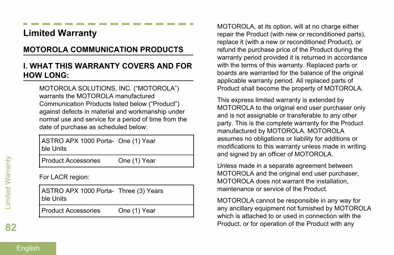
Limited Warranty
MOTOROLA COMMUNICATION PRODUCTS
I. WHAT THIS WARRANTY COVERS AND FORHOW LONG:
MOTOROLA SOLUTIONS, INC. (“MOTOROLA”)warrants the MOTOROLA manufacturedCommunication Products listed below (“Product”)against defects in material and workmanship undernormal use and service for a period of time from thedate of purchase as scheduled below:
ASTRO APX 1000 Porta-ble Units
One (1) Year
Product Accessories One (1) Year
For LACR region:
ASTRO APX 1000 Porta-ble Units
Three (3) Years
Product Accessories One (1) Year
MOTOROLA, at its option, will at no charge eitherrepair the Product (with new or reconditioned parts),replace it (with a new or reconditioned Product), orrefund the purchase price of the Product during thewarranty period provided it is returned in accordancewith the terms of this warranty. Replaced parts orboards are warranted for the balance of the originalapplicable warranty period. All replaced parts ofProduct shall become the property of MOTOROLA.
This express limited warranty is extended byMOTOROLA to the original end user purchaser onlyand is not assignable or transferable to any otherparty. This is the complete warranty for the Productmanufactured by MOTOROLA. MOTOROLAassumes no obligations or liability for additions ormodifications to this warranty unless made in writingand signed by an officer of MOTOROLA.
Unless made in a separate agreement betweenMOTOROLA and the original end user purchaser,MOTOROLA does not warrant the installation,maintenance or service of the Product.
MOTOROLA cannot be responsible in any way forany ancillary equipment not furnished by MOTOROLAwhich is attached to or used in connection with theProduct, or for operation of the Product with any
Lim
ited
War
rant
y
82
English
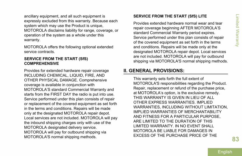
ancillary equipment, and all such equipment isexpressly excluded from this warranty. Because eachsystem which may use the Product is unique,MOTOROLA disclaims liability for range, coverage, oroperation of the system as a whole under thiswarranty.
MOTOROLA offers the following optional extendedservice contracts.
SERVICE FROM THE START (SfS)COMPREHENSIVE
Provides for extended hardware repair coverageINCLUDING CHEMICAL, LIQUID, FIRE, ANDOTHER PHYSICAL DAMAGE. Comprehensivecoverage is available in conjunction withMOTOROLA’S standard Commercial Warranty andstarts from the FIRST DAY the radio is put into use.Service performed under this plan consists of repairor replacement of the covered equipment as set forthin the terms and conditions. Repairs will be madeonly at the designated MOTOROLA repair depot.Local services are not included. MOTOROLA will paythe inbound shipping charges only with use of theMOTOROLA designated delivery service.MOTOROLA will pay for outbound shipping viaMOTOROLA'S normal shipping methods.
SERVICE FROM THE START (SfS) LITE
Provides extended hardware normal wear and tearrepair coverage beginning AFTER MOTOROLA’Sstandard Commercial Warranty period expires.Service performed under this plan consists of repairof the covered equipment as set forth in the termsand conditions. Repairs will be made only at thedesignated MOTOROLA repair depot. Local servicesare not included. MOTOROLA will pay for outboundshipping via MOTOROLA'S normal shipping methods.
II. GENERAL PROVISIONS:This warranty sets forth the full extent ofMOTOROLA'S responsibilities regarding the Product.Repair, replacement or refund of the purchase price,at MOTOROLA’s option, is the exclusive remedy.THIS WARRANTY IS GIVEN IN LIEU OF ALLOTHER EXPRESS WARRANTIES. IMPLIEDWARRANTIES, INCLUDING WITHOUT LIMITATION,IMPLIED WARRANTIES OF MERCHANTABILITYAND FITNESS FOR A PARTICULAR PURPOSE,ARE LIMITED TO THE DURATION OF THISLIMITED WARRANTY. IN NO EVENT SHALLMOTOROLA BE LIABLE FOR DAMAGES INEXCESS OF THE PURCHASE PRICE OF THE
Limited W
arranty
83
English
PRODUCT, FOR ANY LOSS OF USE, LOSS OFTIME, INCONVENIENCE, COMMERCIAL LOSS,LOST PROFITS OR SAVINGS OR OTHERINCIDENTAL, SPECIAL OR CONSEQUENTIALDAMAGES ARISING OUT OF THE USE ORINABILITY TO USE SUCH PRODUCT, TO THEFULL EXTENT SUCH MAY BE DISCLAIMED BYLAW.
III. STATE LAW RIGHTS:SOME STATES DO NOT ALLOW THE EXCLUSIONOR LIMITATION OF INCIDENTAL ORCONSEQUENTIAL DAMAGES OR LIMITATION ONHOW LONG AN IMPLIED WARRANTY LASTS, SOTHE ABOVE LIMITATION OR EXCLUSIONS MAYNOT APPLY.
This warranty gives specific legal rights, and theremay be other rights which may vary from state tostate.
IV. HOW TO GET WARRANTY SERVICE:You must provide proof of purchase (bearing the dateof purchase and Product item serial number) in orderto receive warranty service and, also, deliver or sendthe Product item, transportation and insurance
prepaid, to an authorized warranty service location.Warranty service will be provided by MOTOROLAthrough one of its authorized warranty servicelocations. If you first contact the company which soldyou the Product (e.g., dealer or communicationservice provider), it can facilitate your obtainingwarranty service. You can also call MOTOROLA at1-800-927-2744 US/Canada.
V. WHAT THIS WARRANTY DOES NOTCOVER:
1 Defects or damage resulting from use of theProduct in other than its normal and customarymanner.
2 Defects or damage from misuse, accident, water,or neglect.
3 Defects or damage from improper testing,operation, maintenance, installation, alteration,modification, or adjustment.
4 Breakage or damage to antennas unless causeddirectly by defects in material workmanship.
5 A Product subjected to unauthorized Productmodifications, disassembles or repairs (including,without limitation, the addition to the Product ofnon-MOTOROLA supplied equipment) which
Lim
ited
War
rant
y
84
English
adversely affect performance of the Product orinterfere with MOTOROLA's normal warrantyinspection and testing of the Product to verify anywarranty claim.
6 Product which has had the serial number removedor made illegible.
7 Rechargeable batteries if:
• any of the seals on the battery enclosure ofcells are broken or show evidence oftampering.
• the damage or defect is caused by charging orusing the battery in equipment or service otherthan the Product for which it is specified.
8 Freight costs to the repair depot.9 A Product which, due to illegal or unauthorized
alteration of the software/firmware in the Product,does not function in accordance withMOTOROLA’s published specifications or the FCCcertification labeling in effect for the Product at thetime the Product was initially distributed fromMOTOROLA.
10 Scratches or other cosmetic damage to Productsurfaces that does not affect the operation of theProduct.
11 Normal and customary wear and tear.
VI. PATENT AND SOFTWARE PROVISIONS:MOTOROLA will defend, at its own expense, any suitbrought against the end user purchaser to the extentthat it is based on a claim that the Product or partsinfringe a United States patent, and MOTOROLA willpay those costs and damages finally awarded againstthe end user purchaser in any such suit which areattributable to any such claim, but such defense andpayments are conditioned on the following:
1 that MOTOROLA will be notified promptly inwriting by such purchaser of any notice of suchclaim,
2 that MOTOROLA will have sole control of thedefense of such suit and all negotiations for itssettlement or compromise, and
3 should the Product or parts become, or inMOTOROLA’s opinion be likely to become, thesubject of a claim of infringement of a UnitedStates patent, that such purchaser will permitMOTOROLA, at its option and expense, either toprocure for such purchaser the right to continueusing the Product or parts or to replace or modifythe same so that it becomes non-infringing or togrant such purchaser a credit for the Product orparts as depreciated and accept its return. The
Limited W
arranty
85
English
depreciation will be an equal amount per year overthe lifetime of the Product or parts as establishedby MOTOROLA.
MOTOROLA will have no liability with respect to anyclaim of patent infringement which is based upon thecombination of the Product or parts furnishedhereunder with software, apparatus or devices notfurnished by MOTOROLA, nor will MOTOROLA haveany liability for the use of ancillary equipment orsoftware not furnished by MOTOROLA which isattached to or used in connection with the Product.The foregoing states the entire liability ofMOTOROLA with respect to infringement of patentsby the Product or any parts thereof.
Laws in the United States and other countriespreserve for MOTOROLA certain exclusive rights forcopyrighted MOTOROLA software such as theexclusive rights to reproduce in copies and distributecopies of such MOTOROLA software. MOTOROLAsoftware may be used in only the Product in whichthe software was originally embodied and suchsoftware in such Product may not be replaced,copied, distributed, modified in any way, or used toproduce any derivative thereof. No other useincluding, without limitation, alteration, modification,reproduction, distribution, or reverse engineering of
such MOTOROLA software or exercise of rights insuch MOTOROLA software is permitted. No license isgranted by implication, estoppel or otherwise underMOTOROLA patent rights or copyrights.
VII. GOVERNING LAW:This Warranty is governed by the laws of the State ofIllinois, U.S.A.
VIII. For Australia OnlyThis warranty is given by Motorola Solutions AustraliaPty Limited (ABN 16 004 742 312) of Tally HoBusiness Park, 10 Wesley Court. Burwood East,Victoria.
Our goods come with guarantees that cannot beexcluded under the Australia Consumer Law. You areentitled to a replacement or refund for a major failureand compensation for any other reasonablyforeseeable loss or damage. You are also entitled tohave the goods repaired or replaced if the goods failto be of acceptable quality and the failure does notamount to a major failure.
Motorola Solutions Australia’s limited warranty aboveis in addition to any rights and remedies you may
Lim
ited
War
rant
y
86
English
have under the Australian Consumer Law. If you haveany queries, please call Motorola Solutions Australiaat 1800 457 439. You may also visit our website: http://www.motorolasolutions.com/XA-EN/Pages/Contact_Us for the most updated warranty terms.
Limited W
arranty
87
English

Notes
Notes
English

APX1000_M1_Back_Covers.fm Page 1 Tuesday, October 14, 2014 12:17 AM
Motorola Solutions, Inc.1303 East Algonquin RoadSchaumburg, Illinois 60196 U.S.A.
MOTOROLA, MOTO, MOTOROLA SOLUTIONS and the Stylized M logo are trademarks or registered trademarks of Motorola Trademark Holdings, LLC and are used under license.All other trademarks are the property of their respective owners. © 2014 and 2015 Motorola Solutions, Inc. All rights reserved.June 2015
*MN000253A01*MN000253A01-BB
APX1000_M1_Back_Covers.fm Page 2 Tuesday, October 14, 2014 12:17 AM