Embed Size (px)
Citation preview
Request for Proposal
Tulsa Transit
17-1701 Fixed Route & BRT CNG Buses
April 14, 2017
1
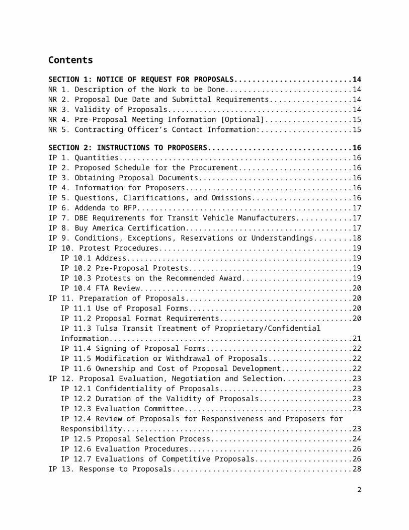
Contents
SECTION 1: NOTICE OF REQUEST FOR PROPOSALS.............................................................................................14NR 1. Description of the Work to be Done..................................................................................................14NR 2. Proposal Due Date and Submittal Requirements...............................................................................14NR 3. Validity of Proposals...........................................................................................................................14NR 4. Pre-Proposal Meeting Information [Optional]...................................................................................15NR 5. Contracting Officer’s Contact Information:........................................................................................15
SECTION 2: INSTRUCTIONS TO PROPOSERS.........................................................................................................16IP 1. Quantities.............................................................................................................................................16IP 2. Proposed Schedule for the Procurement............................................................................................16IP 3. Obtaining Proposal Documents...........................................................................................................16IP 4. Information for Proposers....................................................................................................................16IP 5. Questions, Clarifications, and Omissions.............................................................................................16IP 6. Addenda to RFP....................................................................................................................................17IP 7. DBE Requirements for Transit Vehicle Manufacturers........................................................................17IP 8. Buy America Certification.....................................................................................................................17IP 9. Conditions, Exceptions, Reservations or Understandings...................................................................18IP 10. Protest Procedures.............................................................................................................................19
IP 10.1 Address......................................................................................................................................19IP 10.2 Pre-Proposal Protests................................................................................................................19IP 10.3 Protests on the Recommended Award.....................................................................................19IP 10.4 FTA Review................................................................................................................................20
IP 11. Preparation of Proposals....................................................................................................................20IP 11.1 Use of Proposal Forms...............................................................................................................20IP 11.2 Proposal Format Requirements.................................................................................................20IP 11.3 Tulsa Transit Treatment of Proprietary/Confidential Information...........................................21IP 11.4 Signing of Proposal Forms.........................................................................................................22IP 11.5 Modification or Withdrawal of Proposals.................................................................................22IP 11.6 Ownership and Cost of Proposal Development........................................................................22
IP 12. Proposal Evaluation, Negotiation and Selection................................................................................23IP 12.1 Confidentiality of Proposals.......................................................................................................23IP 12.2 Duration of the Validity of Proposals........................................................................................23IP 12.3 Evaluation Committee...............................................................................................................23IP 12.4 Review of Proposals for Responsiveness and Proposers for Responsibility.............................23IP 12.5 Proposal Selection Process........................................................................................................24IP 12.6 Evaluation Procedures...............................................................................................................26IP 12.7 Evaluations of Competitive Proposals.......................................................................................26
IP 13. Response to Proposals.......................................................................................................................28IP 13.1 Single Proposal Response..........................................................................................................28IP 13.2 Availability of Funds...................................................................................................................28IP 13.3 Tulsa Transit Contract Approval Process...................................................................................28IP 13.4 Tulsa Transit Rights....................................................................................................................28IP 13.5 Execution of Contract................................................................................................................29
IP 14. Conflicts of Interests and Gratuities..................................................................................................29
2
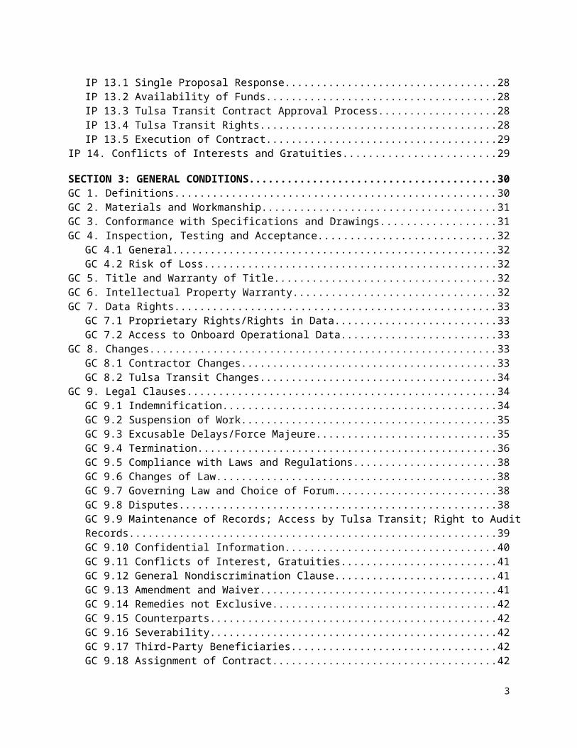
SECTION 3: GENERAL CONDITIONS........................................................................................................................30GC 1. Definitions...........................................................................................................................................30GC 2. Materials and Workmanship..............................................................................................................31GC 3. Conformance with Specifications and Drawings................................................................................31GC 4. Inspection, Testing and Acceptance...................................................................................................32
GC 4.1 General.......................................................................................................................................32GC 4.2 Risk of Loss.................................................................................................................................32
GC 5. Title and Warranty of Title.................................................................................................................32GC 6. Intellectual Property Warranty...........................................................................................................32GC 7. Data Rights..........................................................................................................................................33
GC 7.1 Proprietary Rights/Rights in Data..............................................................................................33GC 7.2 Access to Onboard Operational Data........................................................................................33
GC 8. Changes..............................................................................................................................................33GC 8.1 Contractor Changes...................................................................................................................33GC 8.2 Tulsa Transit Changes................................................................................................................34
GC 9. Legal Clauses.......................................................................................................................................34GC 9.1 Indemnification..........................................................................................................................34GC 9.2 Suspension of Work...................................................................................................................35GC 9.3 Excusable Delays/Force Majeure...............................................................................................35GC 9.4 Termination................................................................................................................................36GC 9.5 Compliance with Laws and Regulations.....................................................................................38GC 9.6 Changes of Law..........................................................................................................................38GC 9.7 Governing Law and Choice of Forum.........................................................................................38GC 9.8 Disputes......................................................................................................................................38GC 9.9 Maintenance of Records; Access by Tulsa Transit; Right to Audit Records...............................39GC 9.10 Confidential Information..........................................................................................................40GC 9.11 Conflicts of Interest, Gratuities................................................................................................41GC 9.12 General Nondiscrimination Clause..........................................................................................41GC 9.13 Amendment and Waiver..........................................................................................................41GC 9.14 Remedies not Exclusive............................................................................................................42GC 9.15 Counterparts............................................................................................................................42GC 9.16 Severability...............................................................................................................................42GC 9.17 Third-Party Beneficiaries..........................................................................................................42GC 9.18 Assignment of Contract...........................................................................................................42GC 9.19 Independent Parties.................................................................................................................42GC 9.20 Survival.....................................................................................................................................42
SECTION 4: SPECIAL PROVISIONS...........................................................................................................................43SP 1. Inspection, Tests and Repairs..............................................................................................................43
SP 1.1 Repairs after Non-Acceptance....................................................................................................43SP 1.2 Repair Performance....................................................................................................................43
SP 2. Deliveries.............................................................................................................................................44SP 2.1 Bus Delivery................................................................................................................................44SP 2.2 SP 2.2 Delivery Schedule.............................................................................................................44
SP 3. Contract Deliverables..........................................................................................................................44SP 4. Options and Option Pricing.................................................................................................................46SP 5. Assignability of Options.......................................................................................................................46
3
SP 6. Payment...............................................................................................................................................46SP 7. Payment Terms - Payment Upon Delivery..........................................................................................47SP 8. Payment of Taxes................................................................................................................................47SP 9. Service and Parts.................................................................................................................................47
SP 9.1 Contractor Service and Parts Support........................................................................................47SP 9.2 Documentation...........................................................................................................................47SP 9.3 Parts Availability Guarantee.......................................................................................................48
SP 10. Federal Motor Vehicle Safety Standards (FMVSS)............................................................................48SP 11. Insurance...........................................................................................................................................48SP 12. Software Escrow Account..................................................................................................................48
SECTION 5: FEDERAL REQUIREMENTS...................................................................................................................49FR 1. Access to Records................................................................................................................................49
FR 1.1 Local Governments.....................................................................................................................49FR 1.2 State Governments.....................................................................................................................49
FR 2. Federal Funding, Incorporation of FTA Terms, and Federal Changes.................................................49FR 3. Federal Energy Conservation Requirements.......................................................................................50FR 4. Civil Rights Requirements...................................................................................................................50FR 5. No Government Obligation to Third Parties.......................................................................................51FR 6. Program Fraud and False or Fraudulent Statements or Related Acts................................................51FR 7. Suspension and Debarment................................................................................................................52FR 8. Disadvantaged Business Enterprise (DBE)..........................................................................................52FR 9. Clean Water Requirements.................................................................................................................53FR 10. Clean Air Requirements....................................................................................................................53FR 11. Compliance with Federal Lobbying Policy.........................................................................................53FR 12. Buy America......................................................................................................................................53FR 13. Testing of New Bus Models...............................................................................................................54FR 14. Pre-Award and Post-Delivery Audits.................................................................................................54FR 15. Cargo Preference...............................................................................................................................55FR 16. Fly America........................................................................................................................................55FR 17. Contract Work Hours and Safety Standards Act...............................................................................55FR 18. ADA Access........................................................................................................................................56
SECTION 6: TECHNICAL SPECIFICATIONS...............................................................................................................57
GENERAL......................................................................................................................................................................57
TS 1. Scope..................................................................................................................................................................57
TS 2. Definitions..........................................................................................................................................................57
TS 3. Referenced Publications...................................................................................................................................63
TS 4. Legal Requirements...........................................................................................................................................63
TS 5. Overall Requirements........................................................................................................................................63TS 5.1 Worker and Protective Measures.....................................................................................................64
4
65TS 5.2 Water Test Description.....................................................................................................................65
a)TS 5.3 Total Bus Operation.........................................................................................................................65TS 5.4 Weight..............................................................................................................................................66TS 5.5 Capacity............................................................................................................................................66TS 5.6 Service Life......................................................................................................................................66TS 5.7 Maintenance and Inspection.............................................................................................................66TS 5.8 Interchangeability.............................................................................................................................67TS 5.9 Training............................................................................................................................................67TS 5.10 Operator Orientation.......................................................................................................................67TS 5.11 Maintenance Orientation................................................................................................................68TS 5.12 Technical Training.........................................................................................................................68TS 5.13 OEM...............................................................................................................................................69TS 5.14 Operating Environment..................................................................................................................69TS 5.15 Noise...............................................................................................................................................69TS 5.16 Fire Safety......................................................................................................................................70TS 5.17 Recycled Products - Respect for the Environment.........................................................................70
TS 6. Physical Size......................................................................................................................................................70TS 6.1 Bus Length.......................................................................................................................................70TS 6.2 Bus Width.........................................................................................................................................71TS 6.3 Bus Height........................................................................................................................................71TS 6.4 Step Height.......................................................................................................................................71TS 6.5 Underbody Clearance.......................................................................................................................71TS 6.6 Ramp Clearances..............................................................................................................................71TS 6.7 Ground Clearance.............................................................................................................................71TS 6.8 Floor Height.....................................................................................................................................72TS 6.9 Interior Headroom............................................................................................................................72TS 6.10 Aisle Width.....................................................................................................................................72
TS 7. Power Requirements.........................................................................................................................................72TS 7.1 Top Speed.........................................................................................................................................73TS 7.2 Gradability........................................................................................................................................73TS 7.3 Acceleration......................................................................................................................................73TS 7.4 Operating Range...............................................................................................................................74TS 7.5 Compressed Natural Gas (CNG)......................................................................................................74TS 7.6 Fuel Economy...................................................................................................................................74
POWERPLANT.............................................................................................................................................................74
TS 8. Engine - CNG......................................................................................................................................................74TS 8.1 Automatic Engine Protection/Shutdown Override Feature..............................................................75TS 8.2 Engine – CNG..................................................................................................................................76TS 8.3 Propulsion System Service...............................................................................................................76TS 8.4 Standard Requirements for a Fast Idle Device.................................................................................76
TS 9. Cooling Systems................................................................................................................................................76TS 9.1 Charge Air Cooling..........................................................................................................................77TS 9.2 Transmission Cooling.......................................................................................................................77
5
TS 10. Transmission (Conventional Powertrain)......................................................................................................77TS 10.1 Retarder..........................................................................................................................................78TS 10.2 Standard Requirement for Retarder Activation..............................................................................78TS 10.3 Mounting........................................................................................................................................78TS 10.4 Engine/Transmission Oil Fill/Filters..............................................................................................78TS 10.5 Engine Compartment Guages.........................................................................................................79TS 10.6 Engine Air Cleaner.........................................................................................................................79TS 10.7 Hydraulic Systems..........................................................................................................................79TS 10.8 Fluid Lines......................................................................................................................................79TS 10.9 Fittings and Clamps........................................................................................................................79TS 10.10 Charge Air Piping.........................................................................................................................80TS 10.11 Radiator........................................................................................................................................80TS 10.12 Oil & Hydraulic Lines..................................................................................................................80
TS 11. Fuel....................................................................................................................................................................80TS 11.1 Fuel Lines.......................................................................................................................................80TS 11.2 Fuel Lines – CNG...........................................................................................................................81
TS 12. Design & Construction....................................................................................................................................81TS 12.1 Labeling..........................................................................................................................................81TS 12.2 Fuel Filler.......................................................................................................................................81
TS 13. Design & Construction - CNG.........................................................................................................................81TS 13.1 Fuel Containers/Cylinders..............................................................................................................81TS 13.2 Installation......................................................................................................................................82TS 13.3 Labeling..........................................................................................................................................82TS 13.4 Pressure Relief Devices (PRDs).....................................................................................................82TS 13.5 Valves.............................................................................................................................................82TS 13.6 Fuel Filler.......................................................................................................................................82TS 13.7 Fueling System...............................................................................................................................83TS 13.8 Defueling System...........................................................................................................................83
TS 14. Emissions & Exhaust......................................................................................................................................83TS 14.1 Exhaust Emissions..........................................................................................................................83TS 14.2 Exhaust System..............................................................................................................................83TS 14.3 Fire Suppression System................................................................................................................84
TS 15. Structure...........................................................................................................................................................84TS 15.1 Design.............................................................................................................................................84TS 15.2 Altoona Testing..............................................................................................................................84TS 15.3 Altoona Testing Report Provided to Agency Prior to Start of Bus Production.............................84
TS 16. Structural Validation Baseline........................................................................................................................84TS 16.1 Structural Analysis.........................................................................................................................84TS 16.2 Distortion........................................................................................................................................85TS 16.3 Resonance and Vibration................................................................................................................85TS 16.4 Engine Compartment Bulkheads....................................................................................................85TS 16.5 Crashworthiness.............................................................................................................................85TS 16.6 Corrosion........................................................................................................................................86TS 16.7 Corrosion-Resistance Requirements for Exposed and Interior Surfaces of Tubing Below Lower Win-dow Level.....................................................................................................................................................86
6
TS 16.8 Towing............................................................................................................................................86TS 16.9 Lifted (Support) Front Axle and Flat Towing Capability..............................................................86TS 16.10 Jacking..........................................................................................................................................87TS 16.11 Hoisting........................................................................................................................................87
TS 17. Floor..................................................................................................................................................................87TS 17.1 Design.............................................................................................................................................87TS 17.2 Strength..........................................................................................................................................87TS 17.3 Construction...................................................................................................................................87TS 17.4 Pressure-Preserved Plywood Panel................................................................................................88
TS 18. Platforms..........................................................................................................................................................88TS 18.1 Operator’s Area..............................................................................................................................88TS 18.2 Operator’s Platform........................................................................................................................88TS 18.3 Farebox...........................................................................................................................................89TS 18.4 Rear Step Area to Rear Area..........................................................................................................89TS 18.5 Rear Area........................................................................................................................................89
TS 19. Wheel Housing.................................................................................................................................................90TS 19.1 Design & Construction...................................................................................................................90
TS 20. Chassis.............................................................................................................................................................90TS 20.1 Suspension......................................................................................................................................90TS 20.2 Springs and Shock Absorbers.........................................................................................................90S 20.3 Lubrication........................................................................................................................................91TS 20.4 Kneeling.........................................................................................................................................91
TS 21. Wheels and Tires.............................................................................................................................................92TS 21.1 Wheels............................................................................................................................................92TS 21.2 Aluminum Wheels..........................................................................................................................92TS 21.3 Tires................................................................................................................................................92
TS 22. Steering.............................................................................................................................................................92TS 22.1 Steering Axle..................................................................................................................................92TS 22.2 Steering Wheel...............................................................................................................................92
Drive Axle....................................................................................................................................................................94
TS 23. Brakes...............................................................................................................................................................94TS 23.1 Service Brake.................................................................................................................................94TS 23.2 Actuation........................................................................................................................................94TS 23.3 Friction Material.............................................................................................................................94TS 23.4 Hubs................................................................................................................................................95TS 23.5 Disc Brakes.....................................................................................................................................95TS 23.6 Parking/Emergency Brake..............................................................................................................95
TS 24. Interlocks..........................................................................................................................................................95TS 24.1 Passenger Door Interlocks..............................................................................................................95
TS 25. Pneumatic System...........................................................................................................................................96TS 25.1 General...........................................................................................................................................96
7
TS 25.2 Air Compressor..............................................................................................................................96TS 25.3 Air Lines & Fittings.......................................................................................................................96TS 25.4 Air Reservoirs.................................................................................................................................97TS 25.5 Air System Dryer............................................................................................................................97
ELECTRICAL, ELECTRONIC AND DATA COMMUNICATION SYSTEMS...............................................................97
TS 26. Electrical, Electronic and Data Communication Systems...........................................................................97TS 26.1 Overview........................................................................................................................................97TS 26.2 Modular Design..............................................................................................................................99TS 26.3 Environmental and Mounting Requirements.................................................................................99TS 26.4 Hardware Mounting.....................................................................................................................101General Electrical Requirements...............................................................................................................101TS 26.5 Batteries........................................................................................................................................101TS 26.6 Battery Cables..............................................................................................................................101TS 26.7 Master Battery Switch..................................................................................................................102TS 26.8 Jump Start Connector...................................................................................................................102TS 26.9 Battery Compartment...................................................................................................................102TS 26.10 Alternator/Regulator...................................................................................................................102TS 26.11 Circuit Protection.......................................................................................................................102TS 26.12 Grounds......................................................................................................................................103TS 26.13 Low Voltage/Low Current Wiring and Terminals.....................................................................103TS 26.14 Electrical Components...............................................................................................................104TS 26.15 Electrical Compartments............................................................................................................104TS 26.16 General Electronic Requirement................................................................................................105TS 26.17 Wiring & Terminals...................................................................................................................105TS 26.18 Discrete Inputs/Outputs (I/O).....................................................................................................105TS 26.19 Shielding.....................................................................................................................................105TS 26.20 Communications.........................................................................................................................105TS 26.21 Radio Frequency (RF)................................................................................................................105TS 26.22 Audio..........................................................................................................................................106TS 26.23 Multiplexing – General..............................................................................................................106TS 26.24 Data Communications – General...............................................................................................106TS 26.25 Drivetrain Level.........................................................................................................................107TS 26.26 Diagnostics, Fault Detection and Data Access...........................................................................107TS 26.27 Programmability (Software).......................................................................................................107
TS 27. Multiplex Level...............................................................................................................................................107TS 27.1 Data Access..................................................................................................................................107TS 27.2 Diagnostics & Fault Detection.....................................................................................................107TS 27.3 Programmability (Software).........................................................................................................107TS 27.4 Electronic Noise Control..............................................................................................................108
OPERATOR PROVISIONS, Controls and instrumentation.................................................................................108
TS 28. Operator Provisions, Controls and Instrumentation..................................................................................108TS 28.1 General.........................................................................................................................................108TS 28.2 Glare.............................................................................................................................................108TS 28.3 Visors/Sun Shades........................................................................................................................108TS 28.4 Operator’s Controls......................................................................................................................109TS 28.5 Normal Bus Operation Instrumentation and Controls..................................................................109
8
TS 28.6 Operator Foot Controls.................................................................................................................116TS 28.7 Pedal Angle..................................................................................................................................116TS 28.8 Pedal Dimensions and Position....................................................................................................116
TS 29. Operator Foot Switches................................................................................................................................116TS 29.1 Floor Mounted Foot Control Platform.........................................................................................116TS 29.2 Turn Control Switches..................................................................................................................116TS 29.3 Foot Switch Control.....................................................................................................................116TS 29.4 Other Floor Mounted Controls.....................................................................................................117
TS 30. Operator’s amenities.....................................................................................................................................117TS 30.1 Coat Hook.....................................................................................................................................117
TS 31. Windshield Wipers and Washers.................................................................................................................117TS 31.1 Windshield Wipers.......................................................................................................................117TS 31.2 Intermittent Wiper with Variable Control....................................................................................117TS 31.3 Non-Synchronized Wipers...........................................................................................................117TS 31.4 Windshield Washers.....................................................................................................................117
TS 32. Operator’s Seat..............................................................................................................................................117TS 32.1 Dimensions...................................................................................................................................117TS 32.2 Seat Pan Cushion Length.............................................................................................................119TS 32.3 Seat Pan Cushion Height Dimensions..........................................................................................119TS 32.4 Seat Pan Cushion Slope................................................................................................................119TS 32.5 Seat Base Fore/Aft Adjustment....................................................................................................119TS 32.6 Seat Pan Cushion Width...............................................................................................................120TS 32.7 Seat Suspension............................................................................................................................120TS 32.8 Seat Back Width...........................................................................................................................120TS 32.9 Seat Back Lumbar Support...........................................................................................................120TS 32.10 Seat Back Angle Adjustment.....................................................................................................120TS 32.11 Seat Belt.....................................................................................................................................120TS 32.12 Seat Control Locations...............................................................................................................120TS 32.13 Seat Structure and Materials.......................................................................................................120TS 32.14 Pedestal.......................................................................................................................................121
TS 33. Mirrors.............................................................................................................................................................121TS 33.1 Exterior Mirrors............................................................................................................................121TS 33.2 Interior Mirrors.............................................................................................................................121
WINDOWS.................................................................................................................................................................121
TS 34. General............................................................................................................................................................121TS 34.1 Windshield....................................................................................................................................121TS 34.2 Glazing.........................................................................................................................................122TS 34.3 Operator’s Side window...............................................................................................................122TS 34.4 Passenger Side Windows..............................................................................................................122
TS 35. HEATING, VENTILATING AND AIR CONDITIONING...................................................................................123TS 35.1 Capacity and Performance............................................................................................................123TS 35.2 Controls and Temperature Uniformity.........................................................................................124TS 35.3 Manual Mode Selection of Climate Control System....................................................................124
9
TS 35.4 Manually Adjustable Temperature Control Set Point..................................................................125
TS 36. Air Flow...........................................................................................................................................................125TS 36.1 Passenger Area.............................................................................................................................125TS 36.2 Operator’s Area............................................................................................................................125TS 36.3 Controls for the Climate Control System (CCS)..........................................................................125TS 36.4 Operator’s Compartment Requirements.......................................................................................126TS 36.5 Air Filtration.................................................................................................................................126TS 36.6 Filters............................................................................................................................................127TS 36.7 Roof Ventilators...........................................................................................................................127
TS 37. EXTERIOR PANELS, FINISHES and Exterior Lighting...............................................................................127TS 37.1 Design...........................................................................................................................................127TS 37.2 Materials.......................................................................................................................................127TS 37.3 Roof-Mounted Equipment............................................................................................................127TS 37.4 Pedestrian Safety..........................................................................................................................127TS 37.5 Easily Replaceable Lower Side Body Panels...............................................................................128TS 37.6 Rain Gutters..................................................................................................................................128TS 37.7 License Plate Provisions...............................................................................................................128TS 37.8 Fender Skirts.................................................................................................................................128TS 37.9 Standard Splash Aprons...............................................................................................................128
TS 38. Service Compartments and Access Doors.................................................................................................128TS 38.1 Access Doors................................................................................................................................128TS 38.2 Access Door Latch/Locks............................................................................................................129
TS 39. Bumpers.........................................................................................................................................................130TS 39.1 Location........................................................................................................................................130TS 39.2 Front Bumper...............................................................................................................................130TS 39.3 Rear Bumper.................................................................................................................................130TS 39.4 Bumper Material...........................................................................................................................131
TS 40. Finish and Color.............................................................................................................................................131TS 40.1 Appearance...................................................................................................................................131TS 40.2 Decals, Numbering and Signing...................................................................................................132TS 40.3 Passenger Information..................................................................................................................132
TS 41. Exterior Lighting............................................................................................................................................132TS 41.1 Backup Light/Alarm.....................................................................................................................133TS 41.2 Doorway Lighting........................................................................................................................133TS 41.3 Service Area Lighting (Interior & Exterior).................................................................................133TS 41.4 Front wheel turn indicator lamps..................................................................................................133
TS 42. INTERIOR PANELS AND FINISHES..............................................................................................................134TS 42.1 General Requirements..................................................................................................................134TS 42.2 Interior Panels...............................................................................................................................134TS 42.3 Operator Area Barrier...................................................................................................................134TS 42.4 Modesty Panels.............................................................................................................................134TS 42.5 Front End......................................................................................................................................135TS 42.6 Rear Bulkhead..............................................................................................................................135TS 42.7 Headlining....................................................................................................................................135
10
TS 42.8 Fastening......................................................................................................................................135TS 42.9 Insulation......................................................................................................................................135TS 42.10 Floor Covering...........................................................................................................................136
TS 43. Interior Lighting.............................................................................................................................................136TS 43.1 Passenger......................................................................................................................................136TS 43.2 Operator Area...............................................................................................................................137TS 43.3 Vestibules/Doors..........................................................................................................................137TS 43.4 Step Lighting................................................................................................................................137TS 43.5 Ramp Lighting..............................................................................................................................137TS 43.6 Fare Collection.............................................................................................................................137TS 43.7 Interior Access Panels and Doors.................................................................................................138TS 43.8 Floor Panels..................................................................................................................................138
TS 44. PASSENGER ACCOMMODATIONS..............................................................................................................138TS 44.1 Passenger Seating.........................................................................................................................138TS 44.2 Hip-to-Knee Room.......................................................................................................................139TS 44.3 Foot Room....................................................................................................................................139TS 44.4 Aisles............................................................................................................................................139TS 44.5 Structure and Design....................................................................................................................140TS 44.6 Construction & Materials.............................................................................................................141TS 44.7 Passenger Assists..........................................................................................................................141TS 44.8 Assists...........................................................................................................................................141TS 44.9 Front Doorway.............................................................................................................................142TS 44.10 Vestibule.....................................................................................................................................142TS 44.11 Rear Doorway(s)........................................................................................................................142TS 44.12 Overhead....................................................................................................................................143TS 44.13 Longitudinal Seat Assists...........................................................................................................143TS 44.14 Wheel Housing Barriers/Assists.................................................................................................143TS 44.15 Passenger Doors.........................................................................................................................143TS 44.16 Rear Door interlocks..................................................................................................................144TS 44.17 Emergency Operation.................................................................................................................144TS 44.18 Door Control...............................................................................................................................144
TS 45. Door Controller..............................................................................................................................................144TS 45.1 Five-Position Operator’s Door Controller....................................................................................144TS 45.2 Loading Systems..........................................................................................................................145TS 45.3 Two Forward-Facing Wheelchair Securement Locations............................................................145TS 45.4 Wheelchair Securing System........................................................................................................145
SIGNAGE AND COMMUNICATION........................................................................................................................146
TS 46. SIGNAGE & COMMUNICATIONS..................................................................................................................146TS 46.1 Destination Signs..........................................................................................................................146TS 46.2 Cables and Accessories................................................................................................................146TS 46.3 Display and Display Illumination.................................................................................................147TS 46.4 Sign Enclosures............................................................................................................................147TS 46.5 Electronic System Requirements..................................................................................................147TS 46.6 Operator Control Unit (OCU)......................................................................................................148
11
TS 47. Passenger Information and Advertising......................................................................................................149TS 47.1 Interior Displays...........................................................................................................................149TS 47.2 Passenger Stop Request/Exit Signal.............................................................................................149TS 47.3 Communications - Video Surveillance System............................................................................149TS 47.4 Mobile Radio System...................................................................................................................149A separate electrical circuit protected with the circuit breaker shall be provided to the radio transceiver TS 47.5 Electronics/Equipment Compartment..........................................................................................149TS 47.6 Radio Mounting............................................................................................................................150TS 47.7 Radio Transmitter.........................................................................................................................150TS 47.8 Antenna........................................................................................................................................150TS 47.9 Voice Annunciation and ITS........................................................................................................150TS 47.10 Automatic Passenger Counting (APC).......................................................................................150TS 47.11 Traffic Signal Priority (TSP)......................................................................................................150
SECTION 7: WARRANTY REQUIREMENTS...........................................................................................................150
BASIC PROVISIONS..................................................................................................................................................151WR 1. Warranty Requirements..................................................................................................................151
WR 1.1 Contractor Warranty...............................................................................................................151WR 1.2 Complete Bus..........................................................................................................................151WR 1.3 Body and Chassis Structure.....................................................................................................151WR 1.4 Propulsion System...................................................................................................................151WR 1.5 Emission Control System (ECS)...............................................................................................151WR 1.6 Subsystems.............................................................................................................................151WR 1.7 Serial Numbers........................................................................................................................152WR 1.8 Extension of Warranty............................................................................................................152WR 1.9 Superior Warranty..................................................................................................................152
WR 2. Repair Procedures...........................................................................................................................152WR 2.1 Repairs by Tulsa Transit..........................................................................................................152WR 2.2 Warranty after Replacement/Repairs.....................................................................................153WR 2.3 Reimbursements.....................................................................................................................153
SECTION 8: QUALITY ASSURANCE........................................................................................................................154QA 1. Contractor’s In-Plant Quality Assurance Requirements.................................................................154QA 2. ISO 9001:2000 Certification.............................................................................................................154
SECTION 9: FORMS AND CERTIFICATIONS..........................................................................................................155CER 1. Proposer’s Checklist......................................................................................................................155CER 2. Acknowledgement of Addenda.....................................................................................................156CER 3. Contractor Service and Parts Support Data..................................................................................157CER 4. REQUEST FOR EQUALS..................................................................................................................158RETURN WITH YOUR PROPOSAL........................................................................................158CER 5. Pricing Schedule..............................................................................................................159CER 6. Pre-Award Evaluation Data Form..................................................................................................161CER 7. Federal Certifications....................................................................................................................162
CER 7.1 Buy America Certification.....................................................................................................162CER 7.2 Debarment and Suspension Certification for Prospective Contractor.................................163CER 7.3 Debarment and Suspension Certification (Lower-Tier Covered Transaction)......................164
12
CER 7.4 Non-Collusion Affidavit.........................................................................................................165CER 7.5 Lobbying Certification...........................................................................................................166CER 7.6 Certificate of Compliance with Bus Testing Requirement....................................................167CER 7.7 DBE Approval Certification...................................................................................................168CER 7.8 Federal Motor Vehicle Safety Standards..............................................................................169
CER 8. Other Certifications.......................................................................................................................170CER 8.1 Proposal Form.......................................................................................................................170CER 8.2 Notice of Award....................................................................................................................171
CER 9. Vehicle Questionnaire...................................................................................................................172
13
RFP 17-1701 Fixed Route & BRT CNG BusesApr 14, 2017
SECTION 1: NOTICE OF REQUEST FOR PROPOSALS NR 1. Description of the Work to be Done The Metropolitan Tulsa Transit Authority and Cleveland Area Rapid Transit (CART), hereinafter referred to as Tulsa Transit, agree to create a joint procurement agreement and to request Proposals for the manufacture and delivery of six (6) thirty-five foot and four (4) forty foot CNG powered fixed route buses as well as eleven (11) forty foot CNG BRT buses with an option to purchase up to forty-two (42) additional CNG ADA Paratransit Vehicles in accordance with the terms and conditions set forth in RFP 17-1701. The Contract shall be a firm-fixed price Contract.
Regarding the options, Tulsa Transit reserves the right to exercise the options for these vehicles for up to five years from the date of the award, yet is not obligated to award any of the options, as the exercise of the options rests with Tulsa Transit. The options may be exercised in any quantity during any time frame during this five year period, but will not exceed forty-two (42) vehicles. Proposer shall submit pricing for the base price of one bus, and then pricing beginning with the time frame between the award date of June 27, 2017 and through June 27, 2022. Pricing for all the options will be evaluated at the time of contract award.
Proposal documents may be obtained from Jack Van Hooser, in person at 510 S. Rockford Avenue, Tulsa, OK 74120 or electronically, at http://tulsatransit.org/about-mtta/procurements-and-dbe/ . Documents requested by mail will be packaged and sent postage paid.
NR 2. Proposal Due Date and Submittal Requirements Proposals must be received by June 9, 2017 at 4:30 PM.
1. Sealed Proposals shall be submitted to either of the following addresses:a. For courier delivery or hand delivery: Jack Van Hooser at Tulsa Transit Administrative offices,
510 S. Rockford Ave., Tulsa, OK 74120Or,
b. By U.S. mail: Jack Van Hooser at Tulsa Transit Administrative offices, 510 S. Rockford Ave., Tulsa, OK 74120
2. Envelopes or boxes containing Proposals shall be sealed and clearly labeled with Tulsa Transit’s Proposal number and the solicitation title: RFP 17-1701 Fixed Route & BRT CNG Buses.
3. Proposers are requested to submit to Tulsa Transit one hard copy marked “Original,” two additional printed copies, and three CDs, each containing an electronic PDF copy of the Proposal. In case of any discrepancies, the hard copy will be considered by Tulsa Transit in evaluating the Proposal, and the electronic version is provided for Tulsa Transit’s administrative convenience only. A Proposal is deemed to be late if it is received by Tulsa Transit after the deadline stated above. Proposals received after the submission deadline may be rejected.
NR 3. Validity of ProposalsProposals and subsequent offers shall be valid for a period of 120 days.
14
RFP 17-1701 Fixed Route & BRT CNG BusesApr 14, 2017
NR 4. Pre-Proposal Meeting Information [Optional]A Pre-Proposal Meeting is not planned. Prospective Proposers are requested to submit written questions to the Contract administrator, identified below. In addition, questions in regards to approved equals may be submitted up to the date specified in “Proposed Schedule for the Procurement.” Responses will be shared with all prospective Proposers. Prospective Proposers are reminded that any changes to the RFP will be by written addenda only.
NR 5. Contracting Officer’s Contact Information:Tulsa TransitName: Jack Van HooserTitle: Accounting & Grants ManagerAddress: 510 S. Rockford Ave., Tulsa, OK 74120Phone number: 918-560-5609Fax number: 918-582-5209E-mail: [email protected] contact: Debra Ruggles 918-560-5603/Randy Cloud 918-560-5619
CARTName: Susan ColdwaterTitle: Manager of OperationsAddress: 510 E. Chesapeake Street, Norman, OK 73019Phone number: 405-325-3322Fax number: 405-325-7490E-Mail: [email protected]
Identification of Source of FundingFinancial support of this project is provided through financial assistance grants from the Federal Transit Administration (FTA), State of Oklahoma, and the City of Tulsa.
Signed and Dated for Posting
___________________________________________________________________ ___________________Signature/Title Date
15
RFP 17-1701 Fixed Route & BRT CNG BusesApr 14, 2017
SECTION 2: INSTRUCTIONS TO PROPOSERSIP 1. QuantitiesThe Work under these Contract documents consists of the manufacture and delivery of a base order of six (6) thirty-five foot fixed route CNG, four (4) forty foot fixed route CNG, and eleven (11) forty foot BRT CNG vehicles with options for forty-two (42) additional vehicles. The term of this contract is five (5) years.
IP 2. Proposed Schedule for the Procurement The following is the solicitation schedule for Proposers:
• Proposer questions and requests on approved equals: May 5, 2017 5:00 PM
• Responses to Proposer’s communications and/or Tulsa Transit addenda: May 12, 2017
• Proposal Due Date: June 9, 2017 at 4:30 PM
• Award: June 27, 2017 12 PM
IP 3. Obtaining Proposal DocumentsProposal documents may be obtained from Jack Van Hooser, in person at 510 S. Rockford Ave., Tulsa, OK 74120 or electronically at http://tulsatransit.org/about-mtta/procurements-and-dbe/ . Documents requested by mail will be packaged and sent postage paid. Documents requested by courier will be packaged and sent only at the Proposers’ expense.
IP 4. Information for Proposers Prospective Proposers are requested to submit written questions to the Contracting Officer identified above. Questions may be submitted up to the date specified in “Proposed Schedule for the Procurement.” Responses will be shared with all prospective Proposers. Prospective Proposers are reminded that any changes to the RFP will be by written addenda only.
IP 5. Questions, Clarifications, and OmissionsAll correspondence, communication, and contact in regard to any aspect of this solicitation or offers shall be only with the Contracting Officer identified above. Unless otherwise instructed by the Contracting Officer, Proposers and their representatives shall not make any contact with or communicate with any member of Tulsa Transit, or its employees and consultants, other than the designated Contracting Officer, in regard to any aspect of this solicitation or offers.
At any time during this procurement up to the time specified in “Proposed Schedule for the Procurement,” Proposers may request, in writing, a clarification or interpretation of any aspect, a change to any requirement of the RFP, or any addenda to the RFP. Requests may include suggested substitutes for specified items and for any brand names, which whenever used in this solicitation shall mean the brand name or approved equal. Such written requests shall be made to the Contracting Officer. The Proposer making the request shall be responsible for its proper delivery to Tulsa Transit as identified on the form Request for Pre-Offer Change or Approved Equal. Any request for a change to any requirement of the
16
RFP 17-1701 Fixed Route & BRT CNG BusesApr 14, 2017
Contract documents must be fully supported with technical data, test results, or other pertinent information showing evidence that the exception will result in a condition equal to or better than that required by the RFP, without a substantial increase in cost or time requirements.
All responses to Request for Pre-Offer Change or Approved Equal shall be provided to all Proposers. Any response that is not confirmed by a written addendum shall not be official or binding on Tulsa Transit.
If it should appear to a prospective Proposer that the performance of the Work under the Contract, or any of the matters relating thereto, is not sufficiently described or explained in the RFP or Contract documents, or that any conflict or discrepancy exists between different parts of the Contract or with any federal, state, local, or Tulsa Transit policies, procedures, or other standard or requirement, the Proposer shall submit a written request for clarification to Tulsa Transit within the time period specified above.
IP 6. Addenda to RFP Tulsa Transit reserves the right to amend the RFP at any time in accordance with “Proposed Schedule for the Procurement.” Any amendments to the RFP shall be described in written addenda. Notification of or the addenda also will be distributed to all such prospective Proposers officially known to have received the RFP. Failure of any prospective Proposer to receive the notification or addenda shall not relieve the Proposer from any obligation under the RFP therein. All addenda issued shall become part of the RFP. Prospective Proposers shall acknowledge the receipt of each individual addendum in their Proposals on the form Acknowledgement of Addenda. Failure to acknowledge in the Proposal receipt of addenda may at Tulsa Transit’s sole option disqualify the Proposal.
If Tulsa Transit determines the addenda may require significant changes in the preparation of Proposals, the deadline for submitting the Proposals may be postponed no less than ten (10) days from the date of issuance of addenda or by the number of days that Tulsa Transit determines will allow Proposers sufficient time to revise their Proposals. Any new Due Date shall be included in the addenda.
IP 7. DBE Requirements for Transit Vehicle Manufacturers Pursuant to Title 49, Code of Federal Regulations, Part 26.49, a Proposer, as a condition of being authorized to respond to this solicitation, must certify by completing the form DBE Approval Certification that it has on file with the Federal Transportation Administration (FTA) an approved or not disapproved annual disadvantaged business enterprise (DBE) subcontracting participation goal.
IP 8. Buy America CertificationThis Contract is subject to the “Buy America” requirements of 49 United States Code (USC) §5323(j) and 49 Code of Federal Regulations (CFR) Part 661, as may be amended from time to time, and applicable federal regulations. Prospective Proposers’ attention is directed to 49 CFR §661.11, “Rolling Stock Procurements.” Prospective Proposers have the responsibility to comply with the cited and any governing statutes and regulations, including official interpretations.
A Proposer shall submit to Tulsa Transit the appropriate Buy America certification, included in this document, with all offers on FTA-funded contracts. Proposals that are not accompanied by a properly completed Buy America certification are subject to the provisions of 49 CFR 661.13 and will be rejected as nonresponsive.
17
RFP 17-1701 Fixed Route & BRT CNG BusesApr 14, 2017
The two signature blocks on the Buy America certificate are mutually exclusive. Proposers shall sign only one signature block on the certificate. Signing both signature blocks will make the Proposal nonresponsive. A false certification is a criminal act in violation of 18 USC §1001.
A Proposer who has submitted an incomplete Buy America certificate or incorrect certificate of noncompliance through inadvertent or clerical error (but not including failure to sign the certificate, submission of certificates of both compliance and noncompliance, or failure to submit any certification), may submit to the FTA chief counsel within ten (10) days of Proposal opening a written explanation of the circumstances surrounding the submission of the incomplete or incorrect certification in accordance with 28 USC §1746, sworn under penalty of perjury, stating that the submission resulted from inadvertent or clerical error. The Proposer will also submit evidence of intent, such as information about the origin of the product, invoices, or other working documents. The Proposer will simultaneously send a copy of this information to Tulsa Transit.
The FTA Chief Counsel may request additional information from the Proposer, if necessary. Tulsa Transit may not make Contract award until the FTA Chief Counsel issues his or her determination, except as provided in 49 CFR Part 661.15(m).
Certification based on ignorance of proper application of the Buy America requirements is not an inadvertent or clerical error.
A waiver from the Buy America provisions will be sought by Tulsa Transit from the FTA, for the proposed awardee, if the grounds for a waiver exist. All Proposers seeking a waiver must submit to Tulsa Transit a timely request in writing, which shall include the facts and justification to support the granting of the waiver. Such waiver from the Buy America provisions may be granted if the FTA determines the following:
1. The application would be inconsistent with the public interest; 2. Materials are not produced in the United States in sufficient and reasonably available quantities and
of a satisfactory quality; or 3. Inclusion of domestic material will increase the cost of the overall Contract by more than 25
percent.
Any party may petition the FTA to investigate a successful Proposer’s compliance with the Buy America certification. The procedures are set out in 49 CFR Part 661.15. If the FTA determines the evidence indicates noncompliance, the FTA will require Tulsa Transit to initiate an investigation. The successful Proposer has the burden of proof to establish compliance with its certification. If the successful Proposer fails to so demonstrate compliance, then the successful Proposer will be required to substitute sufficient domestic materials without revision of the original Contract terms. Failure to do so will be a breach of the Contract and may lead to the initiation of debarment proceedings under 49 CFR Part 29.
IP 9. Conditions, Exceptions, Reservations or UnderstandingsProposers are cautioned to limit exceptions, conditions, and limitations to the provisions of this RFP, as they may be determined to be so fundamental as to cause rejection of the Proposal for not responding to the requirements of the RFP.
Any and all Deviations must be explicitly, fully, and separately stated in the Proposal by completing Form for Proposal Deviation, setting forth at a minimum the specific reasons for each Deviation so that it can be fully considered and, if appropriate, evaluated by Tulsa Transit. All Deviations shall be evaluated in accordance
18

RFP 17-1701 Fixed Route & BRT CNG BusesApr 14, 2017
with the appropriate evaluation criteria and procedures and may result in the Proposer receiving a less favorable evaluation than without the Deviation.
Form for Proposal Deviation shall be included in the Technical package.
IP 10. Protest ProceduresAll protests must be in writing, stating the name and address of protestor, a contact person, Contract number and title. Protests shall specify in detail the grounds of the protest and the facts supporting the protest.
IP 10.1 AddressAll protests must be addressed as follows:
• Tulsa Transit Contact: Jack Van Hooser – [email protected] • For special delivery or hand delivery: 510 S. Rockford Ave., Tulsa, OK 74120• For U.S. Mail: 510 S. Rockford Ave., Tulsa, OK 74120
Protests not properly addressed to the address shown above may not be considered by Tulsa Transit.
Copies of Tulsa Transit’s protest procedures and the protest provisions of FTA Circular 4220.1F or its successor may be obtained from Jack Van Hooser, 510 S. Rockford Ave., Tulsa, OK 74120 918-560-5609. Proposals will be opened and a Notice of Award will be issued by Tulsa Transit in accordance with Tulsa Transit’s protest procedures and the protest provisions of FTA Circular 4220.1F or its successor.
IP 10.2 Pre-Proposal ProtestsPre-Proposal protests are protests based upon the content of the solicitation documents. Three copies of Pre-Proposal protests must be received by Tulsa Transit’s office no later than ten (10) calendar days prior to the Due Date. Protests will be considered and either denied or sustained in part or in whole, in writing, in a manner that provides verification of receipt, prior to the Due Date for Proposals. A written decision specifying the grounds for sustaining all or part of or denying the protest will be transmitted to the protestor prior to the Due Date for Proposals in a manner than provides verification of receipt prior to the Due Date for Proposals. If the protest is sustained, the Proposal Due Date may be postponed and an addendum issued to the solicitation documents or, at the sole discretion of Tulsa Transit, the solicitation may be canceled. If the protest is denied, Proposals will be received and opened on the scheduled date unless a protest is filed with FTA. See “FTA Review,” below.
IP 10.3 Protests on the Recommended AwardAll Proposers will be notified of the recommended award. This notice will be transmitted to each Proposer at the address contained in its Proposal form in a manner that provides verification of receipt. Any Proposer whose Proposal has not lapsed may protest the recommended award on any ground not specified in “Pre-Proposal Protests,” above. Three (3) copies of a full and complete written statement specifying in detail the grounds of the protest and the facts supporting the protest must be received by Tulsa Transit at the appropriate address in “Address,” above, no later than ten (10) calendar days after the date such notification is received. Prior to the issuing of the Notice of Award, a written decision stating the grounds for allowing or denying the protest will be transmitted to the protestor and the Proposer recommended for award in a manner that provides verification of receipt.
19
RFP 17-1701 Fixed Route & BRT CNG BusesApr 14, 2017
IP 10.4 FTA ReviewAfter such administrative remedies have been exhausted, an interested party may file a protest with the Federal Transit Administration of the U.S. Department of Transportation pursuant to the procedures provided in the FTA C 4220.1F or its successor. FTA review is limited to the alleged failure of Tulsa Transit to have written protest procedures, the alleged failure of Tulsa Transit to follow those procedures, the alleged failure of Tulsa Transit to review a protest, or the alleged violation of federal law or regulation.
IP 11. Preparation of ProposalsIP 11.1 Use of Proposal Forms Proposers are advised the forms contained in this RFP are required to be used for submission of a Proposal.
IP 11.2 Proposal Format RequirementsProposals shall be submitted in four separately sealed packages identified below. Each package shall be marked as specified below and shall contain all of the Proposal documents for which the package is required to be marked and shall include no other documents. These same requirements shall apply to any best and final offers (BAFOs) that may be requested.
Proposers shall submit one original (marked clearly as such), two hard copies and three CDs, containing an electronic PDF copy of the Proposal to Tulsa Transit. In case of any discrepancies, the original will be considered by Tulsa Transit in evaluating the Proposal, and the electronic version is provided for Tulsa Transit’s administrative convenience only.
The hard-copy Proposals shall be prepared double-sided on 8½ × 11 in. paper in at least 11-point font. The hard copies shall be contained in three-ring binders, the contents of which are identified on the outside. Use of 11 × 17 in. foldout sheets for large tables, charts, or diagrams is permissible but should be limited. Elaborate formatting is not necessary. Do not provide promotional or advertising information, unless this information is requested and/or is necessary to support the technical submittal.
Package 1: Technical Proposal Requirements
1. Letter of Transmittal2. Technical Proposal 3. Acknowledgement of Addenda4. Contractor Service and Parts Support Data5. Form for Proposal Deviation (without price data)6. Vehicle Questionnaire7. References and Non-Priced Information 8. Engineering organization chart, engineering change control procedure, field modification
process9. Manufacturing facilities plant layout, other contracts, staffing10. Production and delivery schedule and other Contract commitments for the duration of this
Contract11. Management Plan
Package 2: Price Proposal Requirements
20
RFP 17-1701 Fixed Route & BRT CNG BusesApr 14, 2017
Each Price Proposal shall be on the prescribed Proposal form(s) and shall be for the entire Contract, including all Proposal items.
1. Letter of Transmittal2. Pricing Schedule, (including but not limited to such pricing elements as option buses, spare parts
package, manuals, training, special tools and test equipment)
The Proposer is required to complete and execute Tulsa Transit’s Pricing Schedule, contained as part of the Proposal documents, and provide same in the Price Proposal. The Contractor shall be liable for payment of all local taxes applicable to the complete bus as delivered and should add these amounts to the Proposal price.
Package 3: Qualification Package Requirements1. Pre-Award Evaluation Data Form 2. A copy of the three (3) most recent financial statements audited by an independent third party or a
statement from the Proposer regarding how financial information may be reviewed by Tulsa Transit3. Letter for insurance, indicating the Contractor’s ability to obtain the insurance coverage in
accordance with the RFP requirements4. Letter from a surety for a Performance Guarantee, if required, indicating the Contractor’s ability to
obtain financial guarantees in accordance with the RFP requirements5. Form for Proposal Deviation, if applicable (without price data)6. Proposal Form7. All federal certifications: Buy America Certification, Debarment and Suspension Certification for
Prospective Contractor, Debarment and Suspension Certification (Lower-Tier Covered Transaction), Non-Collusion Affidavit, Lobbying Certification, Certificate of Compliance with Bus Testing Requirement, DBE Approval Certification, and Federal Motor Vehicle Safety Standards
Package 4: Proprietary/Confidential Information Package RequirementsThe Proposer is directed to collect and submit any information it deems to be proprietary or confidential in nature in a separate marked and sealed package. If there is no confidential information, the Proposer should include a statement to that effect. Subject package shall be submitted in accordance with the terms and conditions governing the submittal of proposer’s Proposal to this RFP. Blanket-type identification by designating whole pages or sections as containing proprietary information, trade secrets, or confidential commercial and financial information will not ensure confidentiality. The specific proprietary information, trade secrets, or confidential commercial and financial information must be clearly identified as such.
The Proposer is advised that Tulsa Transit is public and as such may be subject to certain state and/or local Public Records Act provisions regarding the release of information concerning this RFP. If a request is received by Tulsa Transit for the release of Proposer’s propriety/confidential information, subject request will be referred to the Proposer for review and consideration. If Proposer chooses to declare the information proprietary/confidential and withhold it from release, it shall defend and hold harmless Tulsa Transit from any legal action arising from such a declaration.
IP 11.3 Tulsa Transit Treatment of Proprietary/Confidential InformationAccess to government records is governed by the Oklahoma law. Except as otherwise required to be disclosed by applicable Oklahoma law, Tulsa Transit will exempt from disclosure proprietary information identified in Package 4.
21
RFP 17-1701 Fixed Route & BRT CNG BusesApr 14, 2017
Upon a request for records from a third party regarding this Proposal, Tulsa Transit will notify the Proposer in writing. The Proposer must respond within three (3) business days with the identification of any and all “proprietary, trade secret, or confidential commercial or financial” information. Failure to respond within the allowed period shall be deemed an approval to release. The Proposer shall indemnify Tulsa Transit’s defense costs associated with its refusal to produce such identified information; otherwise, the requested information may be released.
Tulsa Transit shall employ sound business practices no less diligent than those used for Tulsa Transit’s own confidential information to protect the confidence of all licensed technology, software, documentation, drawings, schematics, manuals, data, and other information and material provided by Proposers and the Contractor pursuant to the Contract that contain confidential commercial or financial information, trade secrets or proprietary information as defined in or pursuant to the State of Oklahoma law against disclosure of such information and material to third parties, except as permitted by the Contract. The Contractor shall be responsible for ensuring that confidential commercial or financial information, trade secrets, or proprietary information — with such determinations to be made by Tulsa Transit in its sole discretion — bears appropriate notices relating to its confidential character.
IP 11.4 Signing of Proposal FormsProposals shall include firm name (and, in the event that the Proposer is a joint venture, the names of the individual firms comprising the joint venture); business address; and the name, title and business address of the responsible individual(s) with their telephone, facsimile (fax) numbers, and email address who may be contacted during the Proposal evaluation period for scheduling oral presentations and for receiving notices from Tulsa Transit. The Proposer shall submit with their Proposal a copy of the joint venture agreement.
Proposals shall be signed by those individual(s) authorized to bind the Proposer. The Proposer shall submit evidence of the official’s authority to act for and bind the Proposer in all matters relating to the Proposal. (In the event the Proposer is a joint venture or consortium, a representative of each of the members of the joint venture or consortium shall execute the Proposal. Each joint venture or consortium member is jointly and severally liable for the joint venture or consortium.)
IP 11.5 Modification or Withdrawal of ProposalsA modification of a Proposal already received will be accepted by Tulsa Transit only if the modification is received prior to the Proposal Due Date, is specifically requested by Tulsa Transit, or is made with a requested BAFO. All modifications shall be made in writing, executed, and submitted in the same form and manner as the original Proposal.
A Proposer may withdraw a Proposal already received prior to the Proposal Due Date by submitting to Tulsa Transit, in the same manner as the original Proposal, a written request for withdrawal executed by the Proposer’s authorized representative. After the Proposal Due Date, a Proposal may be withdrawn only if Tulsa Transit fails to award the Contract within the Proposal validity period prescribed in “Duration of the Validity of Proposals,” or any agreed-upon extension thereof. The withdrawal of a Proposal does not prejudice the right of a Proposer to submit another Proposal within the time set for receipt of Proposals.
IP 11.6 Ownership and Cost of Proposal DevelopmentAll Proposals will become the property of Tulsa Transit. This RFP does not commit Tulsa Transit to enter into a Contract, to pay any costs incurred in the preparation or presentation of a Proposal, nor to procure or contract for the equipment.
22
RFP 17-1701 Fixed Route & BRT CNG BusesApr 14, 2017
IP 12. Proposal Evaluation, Negotiation and Selection Proposals will be evaluated, negotiated, selected, and any award made in accordance with the criteria and procedures described below. The approach and procedures are those that are applicable to a competitive negotiated procurement whereby Proposals are evaluated to determine which Proposals are within a Competitive Range. Discussions and negotiations may then be carried out with Proposers within the Competitive Range, after which BAFOs may be requested.
However, Tulsa Transit may select a Proposal for award without any discussions or negotiations or request for any BAFOs. Subject to Tulsa Transit’s right to reject any or all Proposals, the Proposer whose Proposal is found to be most advantageous to Tulsa Transit will be selected, based upon consideration of the criteria of “Proposal Selection Process,” below.
IP 12.1 Confidentiality of Proposals Proposals will not be publicly opened. All Proposals and evaluations will be kept strictly confidential throughout the evaluation, negotiation, and selection process, except as otherwise required by applicable law. Only the members of the Selection Committee and Evaluation Team and other Tulsa Transit officials, employees, and agents having a legitimate interest will be provided access to the Proposals and evaluation results during this period.
IP 12.2 Duration of the Validity of ProposalsProposals and subsequent offers shall be valid for the period stated in “Section 1: Notice of Request for Proposals.” Tulsa Transit may request Proposers to extend the period of time specified herein by written agreement between Tulsa Transit and the Proposer(s) concerned.
IP 12.3 Evaluation Committee An Evaluation Committee, which will include officers, employees, and agents of Tulsa Transit, will be established. The Evaluation Committee will carry out the detailed evaluations, including establishing the Competitive Range, carrying out negotiations, and making the selection of the Proposer, if any, that may be awarded the Contract.
The Evaluation Committee may report its recommendations and findings to the appropriate Tulsa Transit individual or body responsible for awarding the Contract.
IP 12.4 Review of Proposals for Responsiveness and Proposers for Responsibility Each Proposal will be reviewed to determine if the Proposal is responsive to the submission requirements outlined in this RFP and if the Proposer is responsible.
A responsive Proposal is one that follows the requirements of this RFP, includes all documentation, is submitted in the format outlined in this RFP, is of timely submission, and has the appropriate signatures as required on each document. Failure to comply with these requirements may result in the Proposal being deemed nonresponsive.
A responsible Proposer is one that demonstrates the capability to satisfy the commercial and technical requirements set forth in the Solicitation. A Proposer’s failure to demonstrate that it is responsible may result in the Proposal being rejected.
23
RFP 17-1701 Fixed Route & BRT CNG BusesApr 14, 2017
Any Proposal found to be nonresponsive or Proposer that is found to be non-responsible will not be considered further for award. Proposals that do not comply with the RFP instructions and requirements or do not include the required information may be rejected as insufficient and may not be further considered. Tulsa Transit reserves the right to request a Proposer to provide additional information and/or to clarify information. Tulsa Transit’s determination regarding the responsiveness of a Proposal and the responsibility of a Proposer shall be final.
IP 12.5 Proposal Selection ProcessThe following describes the process by which Proposals will be evaluated and a selection made for a potential award. Any such selection of a Proposal shall be made by consideration of only the criteria set forth below.
“Qualification Requirements” specifies the requirements for determining responsible Proposers, all of which must be met by a Proposer to be found qualified. Final determination of a Proposer’s qualification will be made based upon all information received during the evaluation process and as a condition for award.
“Proposal Evaluation Criteria” contains all the evaluation criteria, and their relative order of importance, by which a Proposal from a qualified Proposer will be considered for selection. An award, if made, will be to a responsible Proposer for a Proposal that is found to be in Tulsa Transit’s best interests, based on price and other evaluation criteria considered. The procedures to be followed for these evaluations are provided in “Evaluation Procedures,” below.
Qualification RequirementsThe following are the requirements for qualifying responsible Proposers. All of these requirements should be met; therefore, they are not listed by any particular order of importance. Any Proposal that the Evaluation Committee finds not to meet these requirements, and cannot be made to meet these requirements, may be determined by the Evaluation Committee not to be responsible and the Proposal rejected. The requirements are as follows:
1. Sufficient financial strength, resources, and capability to finance the Work to be performed and to complete the Contract in a satisfactory manner, as measured by the following:
Proposer’s financial statements prepared in accordance with generally accepted accounting principles of the jurisdiction in which the Proposer is located, and audited by an independent certified public accountant; or a statement from the Proposer regarding how financial information may be reviewed by Tulsa Transit.
Proposer’s ability to secure financial guarantees, if required, as evidenced by a letter of commitment from an underwriter, surety, or other guarantor confirming that the Proposer can provide the required guarantee.
Proposer’s ability to obtain required insurance with coverage values that meet minimum requirements evidenced by a letter from an underwriter confirming that the Proposer can be insured for the required amount.
2. Evidence that the human and physical resources are sufficient to perform the Contract as specified and to ensure delivery of all equipment within the time specified in the Contract, to include the following:
Engineering, management, and service organizations with sufficient personnel and requisite disciplines, licenses, skills, experience, and equipment to complete the
24
RFP 17-1701 Fixed Route & BRT CNG BusesApr 14, 2017
Contract as required and to satisfy any engineering or service problems that may arise during the warranty period.
Adequate manufacturing facilities sufficient to produce and factory-test equipment on schedule.
A spare parts procurement and distribution system sufficient to support equipment maintenance without delays and a service organization with skills, experience, and equipment sufficient to perform all warranty and on-site Work.
3. Evidence that Proposer is qualified in accordance with the provisions of “Section 8: Quality Assurance.”
4. Evidence of satisfactory performance and integrity on contracts in making deliveries on time, meeting specifications and warranty provisions, parts availability, and steps Proposer took to resolve any judgments, liens, Fleet Defects history, or warranty claims. Evidence shall be by client references.
Proposal Evaluation CriteriaThe following are the complete criteria, listed by their relative degree of importance, by which Proposals from responsible Proposers will be evaluated and ranked for the purposes of determining any Competitive Range and to make any selection of a Proposal for a potential award. Any exceptions, conditions, reservations, or understandings explicitly, fully and separately stated on Form for Proposal Deviation, which do not cause Tulsa Transit to consider a Proposal to be outside the Competitive Range, will be evaluated according to the respective evaluation criteria and sub-criteria that they affect.
The criteria are listed numerically by their relative order of importance. However, certain criteria may have sub-criteria identified that are listed by their relative order of importance within the criterion they comprise. Also, certain sub-criteria may have sub-criteria that are listed by their relative degree of importance within the specific sub-criterion they comprise.
• Vehicle Design (35%)Overall bus design, which includes aesthetic, functionality, and features of the bus structure.
• Price/Delivery (30)%Overall price as indicated on the Price Proposal forms, as well as estimated delivery date. Price will be evaluated on the basis of being advantageous to Tulsa Transit.
• Past Performance (20%)The Proposer’s demonstrated ability to meet contractual obligations, manufacture to specifications, deliver on time, and provide parts and technical support. The Proposer shall provide a listing of properties in the United States to which Proposer completed delivery of similar equipment.
• Technical Description (15%)The Proposer shall provide the following information as a minimum: 1. A complete description of the proposed vehicle in sufficient detail to permit
Tulsa Transit to determine conformance with the specifications including
25
RFP 17-1701 Fixed Route & BRT CNG BusesApr 14, 2017
drawings and technical specifications for the vehicle body and all major components. This also includes the wiring layout and circuit breaker specifications.
2. The recommended preventative maintenance schedules for the proposed. vehicles
3. A proposed interior searing layout showing all seating positions, dimensions, locations, and aisle widths, including a summary indicating the number of seating positions (excluding the operator position) and standing capacity.
4. A complete listing of suggested parts inventory required to support this vehicle with current price detail.
5. A description of the manufacturing facilities to be used to manufacture the vehicles, including location, square footage, and special tooling available to construct the vehicles in a timely manner.
6. A description of support facilities for the proposed vehicles and all major components, including parts support and technical assistance.
Bonus Points (5)The Proposer will be offered up to 5 additional bonus points for Oklahoma certified Disadvantaged Business Enterprise (DBE) participation.
IP 12.6 Evaluation Procedures Proposals will be analyzed for conformance with the instructions and requirements of the RFP and Contract documents. Proposals that do not comply with these instructions and do not include the required information may be rejected as insufficient or not be considered for the Competitive Range. Tulsa Transit reserves the right to request that a Proposer provide any missing information and make corrections. Proposers are advised that the detailed evaluation forms and procedures will follow the same Proposal format and organization specified in “Preparation of Proposals.” Therefore, Proposers should pay close attention to and strictly follow all instructions. Submittal of a Proposal will signify that the Proposer has accepted the whole of the Contract documents, except such conditions, exceptions, reservations, or understandings explicitly, fully and separately stated on the forms and according to the instructions of Form for Proposal Deviation. Any such conditions, exceptions, reservations, or understandings that do not result in the rejection of the Proposal are subject to evaluation under the criteria set forth in “Proposal Selection Process.”
Evaluations will be made in strict accordance with all of the evaluation criteria specified in “Proposal Selection Process,” above. Tulsa Transit will choose the Proposal that it finds to be most advantageous to Tulsa Transit, based upon the evaluation criteria.
IP 12.7 Evaluations of Competitive Proposals1. Qualification of responsible Proposers. Proposals will be evaluated to determine the
responsibility of Proposers. A final determination of a Proposer’s responsibility will be made upon the basis of initial information submitted in the Proposal, any information submitted upon request by Tulsa Transit, information submitted in a BAFO and information resulting from Tulsa Transit inquiry of Proposer’s references and its own knowledge of the Proposer.
2. Detailed evaluation of Proposals and determination of Competitive Range. Tulsa Transit will carry out and document its evaluations in accordance with the criteria and procedures set forth
26
RFP 17-1701 Fixed Route & BRT CNG BusesApr 14, 2017
in “Proposal Selection Process.” Any Proposal deficiencies that may render a Proposal unacceptable will be documented. Tulsa Transit will make specific note of questions, issues, concerns, and areas requiring clarification by Proposers and to be discussed in any meetings with Proposers that Tulsa Transit finds to be within the Competitive Range.
Rankings of the Proposals against the evaluation will then be made for determining which Proposals are within the Competitive Range, or may reasonably be made to be within the Competitive Range.
3. Proposals not within the Competitive Range. Proposers of any Proposals that have been determined by Tulsa Transit as not in the Competitive Range, and that cannot be reasonably made to be within the Competitive Range, will be notified in accordance with Tulsa Transit’s policies.
4. Discussions with Proposers in the Competitive Range. The Proposers whose Proposals are found by Tulsa Transit to be within the Competitive Range, or that may be reasonably made to be within the Competitive Range, will be notified and any questions or requests for clarifications provided to them in writing. Each such Proposer may be invited for an interview and discussions with Tulsa Transit to discuss answers to written or oral questions, clarifications, and any facet of its Proposal.
In the event a Proposal that has been included in the Competitive Range contains conditions, exceptions, reservations, or understandings to any Contract requirements as provided in Form for Proposal Deviation, said conditions, exceptions, reservations, or understandings may be negotiated during these meetings. However, Tulsa Transit shall have the right to reject any and all such conditions and exceptions, and instruct the Proposer to amend its Proposal and remove said conditions and exceptions; and any Proposer failing to do so may cause Tulsa Transit to find such Proposal to be outside the Competitive Range.
No information, financial or otherwise, will be provided to any Proposer about any of the Proposals from other Proposers, to the extent permitted by applicable law. Proposers will not be given a specific price or specific financial requirements they must meet to gain further consideration, except that proposed prices may be considered to be too high with respect to the marketplace or unacceptable. Proposers will not be told of their rankings among the other Proposers prior to Contract award.
5. Factory and site visits. Tulsa Transit reserves the right to conduct factory visits of the Proposer’s facilities and/or the facilities of major sub-suppliers included in the Proposal.
6. Best and final offers. After all interviews have been completed, the Proposers in the Competitive Range may be afforded the opportunity to amend their Proposals and make their BAFOs. The Request for BAFOs shall include the following:
Notice that discussions and negotiations are concluded. A complete listing of the conditions, exceptions, reservations, or understandings that
have been approved. A common date and time for submission of written BAFOs, allowing a reasonable
opportunity for preparation of the written BAFOs.
27
RFP 17-1701 Fixed Route & BRT CNG BusesApr 14, 2017
Notice that if any modification to a BAFO is submitted, it must be received by the date and time specified for the receipt of BAFOs.
Notice to Proposers that do not submit a notice of withdrawal or a BAFO that their immediately previous Proposal will be construed as their BAFO.
Any modification to the initial Proposal made by a Proposer in its BAFO shall be identified in its BAFO. BAFOs will be evaluated by Tulsa Transit according to the same requirements and criteria as the initial Proposals, (“Proposal Selection Process”). Tulsa Transit will make appropriate adjustments to the initial scores for any sub-criteria and criteria that have been affected by any Proposal modifications made by the BAFOs. These final scores and rankings within each criterion will again be arrayed by Tulsa Transit and considered according to the relative degrees of importance of the criteria defined in “Proposal Selection Process.”
Tulsa Transit will then choose the Proposal that it finds to be most advantageous to Tulsa Transit, based upon the evaluation criteria. The results of the evaluations and the selection of a Proposal for any award will be documented.
Tulsa Transit reserves the right to make an award to a Proposer whose Proposal it judges to be most advantageous to Tulsa Transit based upon the evaluation criteria, without conducting any written or oral discussions with any Proposers or solicitation of any BAFOs.
7. Debriefing. Subsequent to the award, the unsuccessful Proposers will be notified and may request a debriefing. Proposers will be debriefed in accordance with Tulsa Transit policies, including information regarding the shortcomings of the Proposal.
IP 13. Response to ProposalsIP 13.1 Single Proposal Response If only one Proposal is received in response to this RFP and it is found by Tulsa Transit to be acceptable, a price or cost analysis, or both, possibly including an audit, may be performed by or for Tulsa Transit. The Proposer has agreed to such analysis by submitting a Proposal in response to this RFP.
IP 13.2 Availability of Funds This procurement is subject to the availability of funding. Funding for Tulsa Transit is made available from the FTA, the State of Oklahoma, and the City of Tulsa.
IP 13.3 Tulsa Transit Contract Approval Process Once a decision has been made by the Tulsa Transit evaluation committee, it must be submitted as a board item to the Tulsa Transit Board of Trustees and voted upon for approval before a contract can be signed.
IP 13.4 Tulsa Transit Rights Tulsa Transit reserves the right to cancel the procurement in whole or in part, at its sole discretion, at any time before the Contract is fully executed and approved on behalf of Tulsa Transit.
Tulsa Transit reserves the right to reject any or all Proposals, to undertake discussions with one or more Proposers, and to accept that Proposal or modified Proposal which, in its judgment, will be most advantageous to Tulsa Transit, considering price and other evaluation criteria. Tulsa Transit reserves the
28
RFP 17-1701 Fixed Route & BRT CNG BusesApr 14, 2017
right to determine any specific Proposal that is conditional or not prepared in accordance with the instructions and requirements of this RFP to be nonresponsive. Tulsa Transit reserves the right to waive any Defects, or minor informalities or irregularities in any Proposal which do not materially affect the Proposal or prejudice other Proposers.
If there is any evidence indicating that two or more Proposers are in collusion to restrict competition or are otherwise engaged in anti-competitive practices, the Proposals of all such Proposers shall be rejected, and such evidence may be a cause for disqualification of the participants in any future solicitations undertaken by Tulsa Transit.
Tulsa Transit may reject a Proposal that includes unacceptable Deviations as provided in Form for Proposal Deviation.
IP 13.5 Execution of Contract The acceptance of a Proposal for award, if made, shall be evidenced in writing by a notice of award of Contract delivered to the Proposer whose Proposal is accepted. Upon notice of award of the Contract to a Proposer, the Proposer shall commence performance under the Contract by furnishing any required bonds, and by furnishing copies of the certificates of insurance required to be procured by the Contractor pursuant to the Contract documents within 30 calendar days after the date of receipt of the notice of award. Failure to fulfill these requirements within the specified time is cause for termination of the Contract under “Termination for Default” in Section 3.
IP 14. Conflicts of Interests and GratuitiesProposers are prohibited from engaging in any practice that may be considered as a conflict of interests under existing Tulsa Transit policies and/or state law, and to refrain from participating in any gifts, favors, or other forms of compensation that may be viewed as a gratuity in accordance with existing policies and laws.
29
RFP 17-1701 Fixed Route & BRT CNG BusesApr 14, 2017
SECTION 3: GENERAL CONDITIONS
GC 1. Definitions The following are definitions of special terms used in this document:
Agency: Metropolitan Tulsa Transit Authority (Tulsa Transit)
Authorized Signer: The person who is executing this Contract on behalf of the Contractor and who is authorized to bind the Contractor.
Best And Final Offer (BAFO): The last Proposal made by a Proposer. If a BAFO is not specifically requested by Tulsa Transit, or if the Proposer does not promptly respond to a request for BAFO, then the most recent, current Proposal is the BAFO.
Class 1 Failure (physical safety): A failure that could lead directly to passenger or operator injury and represents a severe crash situation.
Class 2 Failure (road call): A failure resulting in an en route interruption of revenue service. Service is discontinued until the bus is replaced or repaired at the point of failure.
Competitive Range: The range of proposals that are identified as the most highly rated, unless the range is further reduced for purposes of efficiency.
Contract: The Proposal and its acceptance by Tulsa Transit as manifested by the Contract documents specified in “Section 10: Contract.”
Contracting Officer: The person who is executing this Contract on behalf of Tulsa Transit and who has complete and final authority except as limited herein.
Contractor: The successful Proposer who is awarded a Contract for providing all buses and equipment described in the Contract documents.
Days: Unless otherwise stated, “days” shall mean calendar days.
Defect: Patent or latent malfunction or failure in manufacture, installation, or design of any component or subsystem.
Deviation: Variance from a requirement or specification that does not alter the basis of a contract or adversely affects its performance.
Due Date: The date and time by which Proposals must be received by Tulsa Transit as specified in “Section 1: Notice of Request for Proposals.”
Extended Warranty: A warranty available for purchase above the standard warranty.
30
RFP 17-1701 Fixed Route & BRT CNG BusesApr 14, 2017
Fatigue Failure (Corrosion Fatigue): The mechanical degradation of a material under the joint action of corrosion and cyclic loading.
Pass-Through Warranty: A warranty provided by the Contractor but administered directly with the component Supplier.
Proposal: A promise, if accepted, to deliver equipment and services according to the underlying solicitation of Tulsa Transit documented using the prescribed form in the solicitation, including any Proposal or BAFO.
Proposer: A legal entity that makes a Proposal.
Related Defect: Damage inflicted on any component or subsystem as a direct result of a separate Defect.
Solicitation: Tulsa Transit’s request for proposals.
Superior Warranty: A warranty still in effect after all contractually required warranties have expired. The remaining warranty is administered directly between the sub-Supplier and Tulsa Transit.
Supplier: Any manufacturer, company or Agency providing units, components, or subassemblies for inclusion in the bus that are installed by the Contractor. Supplier items shall require qualification by type and acceptance tests in accordance with requirements defined in “Section 8: Quality Assurance.”
Subcontractor: Any manufacturer, company or Agency providing units, components, or subassemblies for inclusion in the bus that is installed by a Subcontractor. Subcontractor items shall require qualification by type and acceptance tests in accordance with requirements defined in “Section 8: Quality Assurance.”
Work: Any and all labor, supervision, services, materials, machinery, equipment, tools, supplies, and facilities called for by the Contract and necessary to the completion thereof.
GC 2. Materials and Workmanship The Contractor shall be responsible for all materials and workmanship in the construction of the bus and all accessories used, whether the same are manufactured by the Contractor or purchased from a Supplier. This provision excludes any equipment leased or supplied by Tulsa Transit, except insofar as such equipment is damaged by the failure of a part or component for which the Contractor is responsible, or except insofar as the damage to such equipment is caused by the Contractor during the manufacture of the buses.
GC 3. Conformance with Specifications and Drawings Materials furnished and Work performed by the Contractor shall conform to the requirements of the Technical Specifications and other Contract documents. Notwithstanding the provision of drawings, technical specifications, or other data by Tulsa Transit, the Contractor shall have the responsibility of supplying all parts and details required to make the bus complete and ready for service even though such details may not be specifically mentioned in the drawings and specifications. Items that are installed by Tulsa Transit shall not be the responsibility of the Contractor unless they are included in this Contract.
31
RFP 17-1701 Fixed Route & BRT CNG BusesApr 14, 2017
Omissions from the Contract specifications, or the inaccurate description of details of Work that are manifestly necessary to carry out the intent of the Contract specifications, or that are customarily performed, shall not relieve the Contractor from performing such omitted Work or inaccurately described details of the Work, and they shall be performed as if fully and correctly set forth and described.
GC 4. Inspection, Testing and AcceptanceGC 4.1 GeneralTulsa Transit’s Representative shall at all times have access to the Work, the Contractor and, through the Contractor, its Suppliers. The Contractor and its Suppliers shall furnish every reasonable facility for ascertaining that the materials and the workmanship are in accordance with the requirements of the Contract Documents. All Work done shall be subject to Tulsa Transit Representative’s inspection and approval in accordance with the approved Work products developed as a result of the Contract Documents.
The pre-delivery tests and inspections shall be performed at the Contractor’s plant; they shall be performed in accordance with the procedures defined in “Section 8: Quality Assurance”; and they may be witnessed by the resident inspector. When a bus passes these tests and inspections, the resident inspector shall authorize release of the bus.
Within fifteen (15) calendar days after arrival at the designated point of delivery, the bus shall undergo Tulsa Transit tests defined in “Post-Delivery Tests.” If the bus passes these tests or if Tulsa Transit does not notify the Contractor of non-acceptance within 15 calendar days after delivery, then acceptance of the bus by Tulsa Transit occurs on the 15th day after delivery. If the bus fails these tests, it shall not be accepted until the repair procedures defined in “Repairs after Non-acceptance” have been carried out and the bus retested until it passes. Acceptance occurs earlier if Tulsa Transit notifies the Contractor of early acceptance or places the bus in revenue service.
GC 4.2 Risk of LossTulsa Transit shall assume risk of loss of the bus on delivery, as defined in “Bus Delivery.” Prior to this delivery, the Contractor shall have risk of loss of the bus, including any damages sustained during the delivery regardless of the status of title or any payments related to the bus. Operators shall keep a maintenance log en route, and it shall be delivered to Tulsa Transit with the bus. If the bus is released back to the Contractor for any reason, the Contractor has the risk of loss upon such release.
GC 5. Title and Warranty of TitleAdequate documents for registering the bus in Oklahoma shall be provided to Tulsa Transit not less than ten (10) business days before delivery to Tulsa Transit. Upon acceptance of each bus, the Contractor warrants that the title shall pass to Tulsa Transit free and clear of all encumbrances.
GC 6. Intellectual Property WarrantyTulsa Transit shall advise the Contractor of any impending patent suit related to this Contract against Tulsa Transit and provide all information available. The Contractor shall defend any suit or proceeding brought against Tulsa Transit based on a claim that any equipment, or any part thereof, furnished under this Contract constitutes an infringement of any patent, and the Contractor shall pay all damages and costs awarded therein, excluding incidental and consequential damages, against Tulsa Transit. In case said equipment, or any part thereof, is in such suit held to constitute infringement and use of said equipment or parts is enjoined, the Contractor shall, at its own expense and at its option, either procure for Tulsa Transit
32
RFP 17-1701 Fixed Route & BRT CNG BusesApr 14, 2017
the right to continue using said equipment or part, or replace same with non-infringing equipment, or modify it so it becomes non-infringing.
The Contractor’s obligations under this section are discharged and Tulsa Transit shall hold the Contractor harmless with respect to the equipment or part if it was specified by Tulsa Transit and all requests for substitutes were rejected, and the Contractor advised Tulsa Transit under “Questions, Clarifications, and Omissions” of a potential infringement, in which case the Contractor shall be held harmless.
GC 7. Data RightsGC 7.1 Proprietary Rights/Rights in DataThe term “subject data” used in this clause means recorded information, whether or not copyrighted, that is delivered or specified to be delivered under the Contract. It includes the proprietary rights of the following:
• Shop drawings and working drawings• Technical data including manuals or instruction materials, computer or microprocessor software• Patented materials, equipment, devices or processes • License requirements
Tulsa Transit shall protect proprietary information provided by the Contractor to the fullest extent of the law. The Contractor shall grant a non-exclusive license to allow Tulsa Transit to utilize such information in order to maintain the vehicles. In the event that the Contractor no longer provides the information Tulsa Transit has the right to reverse engineer patented parts and software.
Tulsa Transit reserves a royalty-free, non-exclusive, and irrevocable license to reproduce, publish, or otherwise use, and to authorize others to use, the following subject data for its purposes: (1) any subject data required to be developed and first produced in the performance of the Contract and specifically paid for as such under the Contract, whether or not a copyright has been obtained; and (2) any rights of copyright to which the Contractor, Subcontractor, or Supplier purchases ownership for the purpose of performance of the Contract and specifically paid for as such under the Contract. The Contractor agrees to include the requirements of this clause, modified as necessary to identify the affected parties, in each subcontract and supply order placed under the Contract.
GC 7.2 Access to Onboard Operational Data Tulsa Transit grants to the Contractor the right to inspect, examine, download, and otherwise obtain any information or data available from components provided by the Contractor, including, but not limited to, any electronic control modules or other data-collection devices, to the extent necessary to enable Contractor to perform reliability maintenance analysis, corrective action, and/or other engineering type Work for the bus. This right expressly excludes access to information or data collected on any equipment not provided and installed by the Contractor.
GC 8. ChangesGC 8.1 Contractor ChangesAny proposed change in this Contract shall be submitted to Tulsa Transit for its prior approval. Oral change orders are not permitted. No change in this Contract shall be made without the prior written approval of the Contracting Officer. The Contractor shall be liable for all costs resulting from, and/or for satisfactorily
33
RFP 17-1701 Fixed Route & BRT CNG BusesApr 14, 2017
correcting, any specification change not properly ordered by written modification to the Contract and signed by the Contracting Officer.
GC 8.2 Tulsa Transit ChangesTulsa Transit may obtain changes to the Contract by notifying the Contractor in writing. As soon as reasonably possible but no later than thirty (30) calendar days after receipt of the written change order to modify the Contract, the Contractor shall submit to the Contracting Officer a detailed price and schedule Proposal for the Work to be performed. This Proposal shall be accepted or modified by negotiations between the Contractor and the Contracting Officer. At that time, a detailed modification shall be executed in writing by both parties. Disagreements that cannot be resolved within negotiations shall be resolved in accordance with “Disputes,” below. Regardless of any disputes, the Contractor shall proceed with the Work ordered.
GC 9. Legal ClausesGC 9.1 IndemnificationGC 9.1.1 The Contractor shall, to the extent permitted by law: (1) protect, indemnify, and save Tulsa Transit and its officers, employees, and agents, including consultants, harmless from and against any and all liabilities, damages, claims, demands, liens, encumbrances, judgments, awards, losses, costs, expenses, and suits or actions or proceedings, including reasonable expenses, costs, and attorneys’ fees incurred by Tulsa Transit and its officers, employees, and agents, including consultants, in the defense, settlement, or satisfaction thereof, for any injury, death, loss, or damage to persons or property of any kind whatsoever, arising out of or resulting from the intentional misconduct or negligent acts, errors, or omissions of the Contractor in the performance of the Contract, including intentional misconduct, negligent acts, errors, or omissions of its officers, employees, servants, agents, Subcontractors, and Suppliers; and (2) upon receipt of notice and if given authority, shall settle at its own expense or undertake at its own expense the defense of any such suit, action, or proceeding, including appeals, against Tulsa Transit and its officers, employees, and agents, including consultants, relating to such injury, death, loss, or damage. Each party shall promptly notify the other in writing of the notice or assertion of such claim, demand, lien, encumbrance, judgment, award, suit, action, or other proceeding hereunder. The Contractor shall have sole charge and direction of the defense of such suit, action, or proceeding. Tulsa Transit shall not make any admission that might be materially prejudicial to the Contractor unless the Contractor has failed to take over the conduct of any negotiations or defense within a reasonable time after receipt of the notice and authority above provided. Tulsa Transit shall at the request of the Contractor furnish to the Contractor all reasonable assistance that may be necessary for the purpose of defending such suit, action, or proceeding, and shall be repaid all reasonable costs incurred in doing so. Tulsa Transit shall have the right to be represented therein by advisory council of its own selection at its own expense.
GC 9.1.2 The obligations of the Contractor under the above paragraph shall not extend to circumstances where the injury, death, or damages are caused solely by the negligent acts, errors, or omissions of Tulsa Transit, its officers, employees, agents, or consultants, including, without limitation, negligence in: (1) the preparation of the Contract documents, or (2) the giving of directions or instructions with respect to the requirements of the Contract by written order. The obligations of the Contractor shall not extend to circumstances where the injury, death, or damages are caused, in whole or in part, by the negligence of any third-party operator, not including an assignee or Subcontractor of the Contractor, subject to the right of contribution. In case of joint or concurrent negligence of the parties giving rise to a claim or loss against either one or both, each shall have full rights of contribution from the other.
34
RFP 17-1701 Fixed Route & BRT CNG BusesApr 14, 2017
GC 9.2 Suspension of WorkGC 9.2.1. Tulsa Transit may at any time and for any reason within its sole discretion issue a written order to the Contractor suspending, delaying, or interrupting all or any part of the Work for a specified period of time.
GC 9.2.2. The Contractor shall comply immediately with any such written order and take all reasonable steps to minimize costs allocable to the Work covered by the suspension during the period of work stoppage. Contractor shall continue the Work that is not included in the suspension and shall continue such ancillary activities as are not suspended. The Contractor shall resume performance of the suspended Work upon expiration of the notice of suspension, or upon direction from Tulsa Transit.
GC 9.2.3. The Contractor shall be allowed an equitable adjustment in the Contract price (excluding profit) and/or an extension of the Contract time, to the extent that cost or delays are shown by the Contractor to be directly attributable to any suspension. However, no adjustment shall be made under this section for any suspension, delay, or interruption due to the fault or negligence of the Contractor, or for which an equitable adjustment is provided for, or excluded under any other term or condition of the Contract. As soon as reasonably possible but no later than forty-five (45) calendar days, or any other period of time agreed to by the parties, after receipt of the written suspension of work notice, the Contractor shall submit to the Contracting Officer a detailed price and schedule Proposal for the suspension, delay or interruption.
GC 9.3 Excusable Delays/Force MajeureGC 9.3.1. If the Contractor is delayed at any time during the progress of the Work by the neglect or failure of Tulsa Transit or by a cause as described below, then the time for completion and/or affected delivery date(s) shall be extended by Tulsa Transit subject to the following cumulative conditions:
a. The cause of the delay arises after the Notice of Award and neither was nor could have been anticipated by the Contractor by reasonable investigation before such award. Such cause may also include force majeure events such as any event or circumstance beyond the reasonable control of the Contractor, including but not limited to acts of God; earthquake, flood, and any other natural disaster; civil disturbance, strikes, and labor disputes; fires and explosions; war and other hostilities; embargo; or failure of third parties, including Suppliers or Subcontractors, to perform their obligations to the Contractor;
b. The Contractor demonstrates that the completion of the Work and/or any affected deliveries will be actually and necessarily delayed;
c. The Contractor has taken measures to avoid and/or mitigate the delay by the exercise of all reasonable precautions, efforts, and measures, whether before or after the occurrence of the cause of delay; and
d. The Contractor makes written request and provides other information to Tulsa Transit as described in GC 9.3.4 below.
A delay in meeting all of the conditions of this section shall be deemed an excusable delay. Any concurrent delay that does not constitute an excusable delay shall not be the sole basis for denying a request hereunder.
35
RFP 17-1701 Fixed Route & BRT CNG BusesApr 14, 2017
GC 9.3.2. None of the above shall relieve the Contractor of any liability for the payment of any liquidated damages owing from a failure to complete the Work by the time for completion that the Contractor is required to pay pursuant to “Liquidated Damages for Late Delivery of the Bus” for delays occurring prior to, or subsequent to the occurrence of an excusable delay.
GC 9.3.3. Tulsa Transit reserves the right to rescind or shorten any extension previously granted, if subsequently Tulsa Transit determines that any information provided by Contractor in support of a request for an extension of time was erroneous; provided, however, that such information or facts, if known, would have resulted in a denial of the request for an excusable delay. Notwithstanding the above, Tulsa Transit will not rescind or shorten any extension previously granted if the Contractor acted in reliance upon the granting of such extension and such extension was based on information which, although later found to have been erroneous, was submitted in good faith by the Contractor.
GC 9.3.4. No extension or adjustment of time shall be granted unless: (1) written notice of the delay is filed with Tulsa Transit within fourteen (14) calendar days after the commencement of the delay and (2) a written application therefore, stating in reasonable detail the causes, the effect to date and the probable future effect on the performance of the Contractor under the Contract, and the portion or portions of the Work affected, is filed by the Contractor with Tulsa Transit within thirty (30) calendar days after the commencement of the delay. No such extension or adjustment shall be deemed a waiver of the rights of either party under this Contract. Tulsa Transit shall make its determination within thirty (30) calendar days after receipt of the application.
GC 9.4 TerminationGC 9.4.1. Termination for ConvenienceThe performance of Work under this Contract may be terminated by Tulsa Transit in accordance with this clause in whole, or from time to time in part, whenever the contracting officer shall determine that such termination is in the best interest of Tulsa Transit. Any such termination shall be effected by delivery to the Contractor of a notice of termination specifying the extent to which performance of Work under the Contract is terminated, and the date upon which such termination becomes effective.
After receipt of a notice of termination, and except as otherwise directed by the Contracting Officer, the Contractor shall do the following:
• Stop Work under the Contract on the date and to the extent specified in the notice of termination.• Place no further orders or subcontracts for materials, services or facilities, except as may be
necessary for completion of such portion of the Work under the Contract as is not terminated. • Terminate all orders and subcontracts to the extent that they relate to the performance of work
terminated by the notice of termination; assign to Tulsa Transit in the manner, at the times, and to the extent directed by the Contracting Officer, all of the right, title, and interest of the Contractor under the orders and subcontracts so terminated, in which case Tulsa Transit shall have the right, in its discretion, to settle or pay any or all claims arising out of the termination of such orders and subcontracts.
• Settle all outstanding liabilities and all claims arising out of such termination of orders and subcontracts, with the approval or ratification of the Contracting Officer, to the extent he or she may require, which approval or ratification shall be final for all the purposes of this clause.
• Transfer title to Tulsa Transit and deliver in the manner, at the times and to the extent, if any, directed by the Contracting Officer the fabricated or un-fabricated parts, Work in process,
36
RFP 17-1701 Fixed Route & BRT CNG BusesApr 14, 2017
completed Work, supplies, and other material produced as part of, or acquired in connection with the performance of, the Work terminated, and the completed or partially completed plans, drawings, information, and other property which, if the Contract had been completed, would have been required to be furnished to Tulsa Transit.
• Use its best efforts to sell, in the manner, at the times, to the extent, and at the price(s) directed or authorized by the Contracting Officer, any property of the types referred to above, provided, however, that the Contractor shall not be required to extend credit to any purchaser, and may acquire any such property under the conditions prescribed by and at a price(s) approved by the Contracting Officer, and provided further that the proceeds of any such transfer or disposition shall be applied in reduction of any payments to be made by Tulsa Transit to the Contractor under this Contract or shall otherwise be credited to the price or cost of the Work covered by this Contract or paid in such other manner as the Contracting Officer may direct.
• Complete performance of such part of the Work as shall not have been terminated by the notice of termination.
• Take such action as may be necessary, or as the Contracting Officer may direct, for the protection or preservation of the property related to this Contract that is in the possession of the Contractor and in which Tulsa Transit has or may acquire an interest.
The Contractor shall be paid its costs, including Contract close-out costs, and profit on Work performed up to the time of termination. The Contractor shall promptly submit its termination claim to Tulsa Transit to be paid the Contractor. Settlement of claims by the Contractor under this termination for convenience clause shall be in accordance with the provisions set forth in Part 49 of the Federal Acquisition Regulations (48 CFR 49) except that wherever the word “Government” appears, it shall be deleted and the word “Tulsa Transit” shall be substituted in lieu thereof.
GC 9.4.2. Termination for DefaultTulsa Transit may, by written notice of default to the Contractor, terminate the whole or any part of this Contract if the Contractor fails to make delivery of the supplies or to perform the services within the time specified herein or any extension thereof; or if the Contractor fails to perform any of the other material provisions of the Contract, or so fails to make progress as to endanger performance of this Contract in accordance with its terms, and in either of these two circumstances does not cure such failure within a period of ten (10) business days, or such longer period as the Contracting Officer may authorize in writing, after receipt of notice from the Contracting Officer specifying such failure.
If the Contract is terminated in whole or in part for default, Tulsa Transit may procure, upon such terms and in such manner as the Contracting Officer may deem appropriate, supplies or services similar to those so terminated. The Contractor shall be liable to Tulsa Transit for any excess costs for such similar supplies or services, and shall continue the performance of this Contract to the extent not terminated under the provisions of this clause.
Except with respect to defaults of Subcontractors, the Contractor shall not be liable for any excess costs if the failure to perform the Contract arises out of a cause beyond the control and without the fault or negligence of the Contractor. If the failure to perform is caused by the default of a Subcontractor, and if such default arises out of causes beyond the control of both the Contractor and Subcontractor, and without the fault or negligence of either of them, the Contractor shall not be liable for any excess costs for failure to perform, unless the supplies or services to be furnished by the Subcontractor were obtainable from other sources and in sufficient time to permit the Contractor to meet the required delivery schedule.
37
RFP 17-1701 Fixed Route & BRT CNG BusesApr 14, 2017
Payment for completed supplies delivered to and accepted by Tulsa Transit shall be at the Contract price. Tulsa Transit may withhold from amounts otherwise due the Contractor for such completed supplies such sum as the Contracting Officer determines to be necessary to protect Tulsa Transit against loss because of outstanding liens or claims of former lien holders.
If, after notice of termination of this Contract under the provisions of this clause, it is determined for any reason that the Contractor was not in default under the provisions of this clause, or that the default was excusable under the provisions of this clause, the rights and obligations of the parties shall be the same as if the notice of termination had been issued pursuant to termination for convenience of Tulsa Transit.
GC 9.5 Compliance with Laws and RegulationsContractor shall at all times comply with all applicable laws, regulations, policies, procedures, and directives (together, the “Law”), including without limitation, FTA regulations, policies, procedures, and directives, including those listed directly or by reference in the agreement between Tulsa Transit and FTA that funds any part of this Contract, as they may be amended or promulgated from time to time during the term of this Contract. Contractor’s failure to so comply shall constitute a material breach of this Contract.
GC 9.6 Changes of LawChanges of Law that becomes effective after the Proposal Due Date may result in price changes. If a price adjustment is indicated, either upward or downward, it shall be negotiated between Tulsa Transit and the Contractor and the final Contract price will be adjusted upwards or downwards to reflect such changes in Law. Such price adjustment may be audited, where required.
GC 9.7 Governing Law and Choice of ForumThis Contract shall be governed by the laws of Oklahoma without regard to conflict of law rules. The Contractor consents to the jurisdiction of the identified State, County of Tulsa.
GC 9.8 DisputesExcept as otherwise provided in this Contract, any dispute concerning a question of fact arising under or related to this Contract that is not disposed of by agreement shall be decided in accordance with the following steps. However, by mutual agreement the matter may be taken immediately to any higher step in the dispute resolution process, or mutually agreed to alternative dispute resolution process (which may include structured negotiations, mediation, or arbitration) or litigation. Pending final resolution of a dispute hereunder, the Contractor shall proceed diligently with the performance of the Contract and in accordance with the Contracting Officer’s or Chief Executive Officer’s decision, as the case may be.
1. Notice of dispute. All disputes shall be initiated through a written dispute notice submitted by either party to the other party within ten (10) calendar days of the determination of the dispute.
2. Negotiation between contracting officers. The parties shall attempt in good faith to resolve any dispute arising out of or relating to this Contract promptly by negotiation between executives who have authority to settle the controversy and who are at a higher level of management than the people with direct responsibility for administration of this Contract. Any party may give the other party written notice of any dispute not resolved in the normal course of business as provided in (1) above. Within fourteen (14) calendar days after delivery of the dispute notice, the receiving party shall submit to the other party a written response. The dispute notice and written response shall
38
RFP 17-1701 Fixed Route & BRT CNG BusesApr 14, 2017
include: (a) a statement of the party’s position and a summary of the arguments supporting that position, (b) any evidence supporting the party’s position and (c) the name of the executive who will represent that party and of any others who will accompany the executive in negotiations. Within twenty-eight (28) calendar days after delivery of the dispute notice, the Contracting Officer of both parties shall meet at a mutually acceptable time and place, and thereafter as they reasonably deem necessary to attempt to resolve the dispute. All reasonable requests for information by one party to the other shall be honored.
If the matter has not been resolved by these people within forty-two (42) calendar days of the dispute notice, the dispute may be referred to more senior executives of both parties who have authority to settle the dispute and who shall likewise meet to attempt to resolve the dispute.
3. Chief Executive Officer’s decision. Should the dispute not be resolved by negotiation between Contracting Officers, as provided in (2) above, Tulsa Transit’s Contracting Officer from (2) above shall submit a written request for decision to Tulsa Transit’s Chief Executive Officer (CEO) along with all documentation and minutes from the negotiations. The Chief Executive Officer shall issue a written decision within fourteen (14) days of receipt of a request.
A. For disputes involving $50,000 or less, the decision of the CEO shall be administratively final and conclusive. For disputes involving $50,000 or less, it is the intent of the parties that such administratively final and conclusive decision pursuant to either this paragraph or paragraph 4 shall only be overturned if determined by a court of competent jurisdiction to be fraudulent, arbitrary, capricious, unsupported by the evidence, or so grossly erroneous as to imply bad faith. For disputes greater than $50,000, the decision of the CEO shall be administratively final and conclusive unless, within thirty (30) days from the date of delivery of the written decision, the Contractor appeals the decision in writing to Tulsa Transit’s Chief Executive Officer or designee who shall render a written decision within fourteen (14) days of delivery of such written appeal. Such decision by the Chief Executive Officer or his or her designee shall be administratively final and conclusive.
B. Within thirty (30) days of the issuance of any administratively final and conclusive decision under this paragraph, the Contractor shall notify Tulsa Transit in writing of the Contractor’s agreement with the final decision. Failure to provide such written notice of agreement shall indicate intent by the Contractor to litigate the claim.
C. Any dispute that is not resolved by the parties through the operation of the provisions of this paragraph, or any mutually agreed-upon alternative disputes resolution process pursuant to paragraph 4 may be submitted to any court in Oklahoma.
D. Pending final resolution of a dispute hereunder, the Contractor shall proceed diligently with the performance of its obligations under the Contract in accordance with the written directions of Tulsa Transit.
GC 9.9 Maintenance of Records; Access by Tulsa Transit; Right to Audit RecordsIn accordance with 49 CFR § 18.36(i), 49 CFR § 19.48(d), and 49 USC § 5325(a), provided Tulsa Transit is the FTA recipient or a sub-grantee of the FTA recipient, the Contractor agrees to provide Tulsa Transit, FTA, the Comptroller General of the United States, the Secretary of the U.S. Department of Transportation, Oklahoma, or any of their duly authorized representatives access to any books, documents, papers, and
39
RFP 17-1701 Fixed Route & BRT CNG BusesApr 14, 2017
records of the Contractor that are directly pertinent to or relate to this Contract (1) for the purpose of making audits, examinations, excerpts, and transcriptions and (2) when conducting an audit and inspection.
1. In the event of a sole source Contract, single Proposal, single responsive Proposal, or competitive negotiated procurement, the Contractor shall maintain and the Contracting Officer, the U.S. Department of Transportation (if applicable) or the representatives thereof shall have the right to examine all books, records, documents, and other cost and pricing data related to the Contract price, unless such pricing is based on adequate price competition, established catalog or market prices of commercial items sold in substantial quantities to the public, or prices set by law or regulation, or combinations thereof. Data related to the negotiation or performance of the Contract shall be made available for the purpose of evaluating the accuracy, completeness, and currency of the cost or pricing data. The right of examination shall extend to all documents necessary for adequate evaluation of the cost or pricing data, along with the computations and projections used therein, including review of accounting principles and practices that reflect properly all direct and indirect costs anticipated for the performance of the Contract.
2. For Contract modifications or change orders the Contracting Officer, the U.S. Department of Transportation, if applicable, or their representatives shall have the right to examine all books, records, documents, and other cost and pricing data related to a Contract modification, unless such pricing is based on adequate price competition, established catalog or market prices of commercial items sold in substantial quantities to the public, or prices set by law or regulation, or combinations thereof. Data related to the negotiation or performance of the Contract modification or change order shall be made available for the purpose of evaluating the accuracy, completeness and currency of the cost or pricing data. The right of examination shall extend to all documents necessary for adequate evaluation of the cost or pricing data, along with the computations and projections used therein, either before or after execution of the Contract modification or change order for the purpose of conducting a cost analysis. If an examination made after execution of the Contract modification or change order reveals inaccurate, incomplete or out-of-date data, the Contracting Officer may renegotiate the Contract modification or change order price adjustment, and Tulsa Transit shall be entitled to any reductions in the price that would result from the application of accurate, complete or up-to-date data. Lines 2 to end of paragraph are off by one space on the left margin.
The requirements of this section are in addition to other audit, inspection, and record-keeping provisions specified elsewhere in the Contract documents.
GC 9.10 Confidential InformationAccess to government records is governed by the City of Tulsa and the State of Oklahoma except as otherwise required by the City of Tulsa and the State of Oklahoma, Tulsa Transit will exempt from disclosure proprietary information, trade secrets, and confidential commercial and financial information submitted or disclosed during the Contract period. Any such proprietary information, trade secrets, or confidential commercial and financial information that a Contractor believes should be exempted from disclosure shall be specifically identified and marked as such. Blanket-type identification by designating whole pages or sections as containing proprietary information, trade secrets, or confidential commercial and financial information will not ensure confidentiality. The specific proprietary information, trade secrets, or confidential commercial and financial information must be clearly identified as such.
40
RFP 17-1701 Fixed Route & BRT CNG BusesApr 14, 2017
Upon a request for records from a third party regarding the Contract, Tulsa Transit will notify the Contractor in writing. The Contractor must respond within twenty (20) days with the identification of any and all “proprietary, trade secret or confidential commercial or financial” information, and the Contractor shall indemnify Tulsa Transit’s defense costs associated with its refusal to produce such identified information; otherwise, the requested information may be released.
Tulsa Transit shall employ sound business practices no less diligent than those used for Tulsa Transit’s own confidential information to protect the confidence of all licensed technology, software, documentation, drawings, schematics, manuals, data, and other information and material provided by the Contractor pursuant to the Contract that contain confidential commercial or financial information, trade secrets, or proprietary information as defined in or pursuant to the City of Tulsa and the State of Oklahoma against disclosure of such information and material to third parties except as permitted by the Contract. The Contractor shall be responsible for ensuring that confidential commercial or financial information, trade secrets, or proprietary information, with such determinations to be made by Tulsa Transit in its sole discretion, bears appropriate notices relating to its confidential character.
During the performance of the Work under the Contract, it may be necessary for the Contractor to make confidential information available to the Tulsa Transit. Tulsa Transit agrees to use all such information solely for the performance of the Work under the Contract and to hold all such information in confidence and not to disclose same to any third party without the prior written consent of the Contractor. Likewise, Tulsa Transit agrees that all information developed in connection with the Work under the Contract shall be used solely for the performance of the Work under the Contract, and shall be held in confidence and not disclosed to any third party without the prior written consent of the Contractor.
This Confidentiality section shall survive the termination or expiration of the Contract.
GC 9.11 Conflicts of Interest, GratuitiesNo member, officer, or employee of Tulsa Transit or of a local public body during his or her tenure, or one year thereafter, shall have any interest, direct or indirect, in this Contract or the proceeds thereof.
GC 9.12 General Nondiscrimination ClauseIn connection with the performance of Work provided for under this Contract, the Contractor agrees that it will not, on the grounds of race, religious creed, color, national origin, ancestry, physical disability, medical condition, marital status, sex, sexual orientation, or age, discriminate or permit discrimination against any person or group of people in any manner prohibited by federal, state, or local laws.
GC 9.13 Amendment and WaiverGC 9.13.1. AmendmentAny modification or amendment of any provisions of any of the Contract documents shall be effective only if in writing, signed by authorized representatives of both Tulsa Transit and Contractor, and specifically referencing this Contract.
GC 9.13.2. WaiverIn the event that either party elects to waive its remedies for any breach by the other party of any covenant, term, or condition of this Contract, such waiver shall not limit the waiving party’s remedies for any succeeding breach of that or of any other term, covenant, or condition of this Contract.
41
RFP 17-1701 Fixed Route & BRT CNG BusesApr 14, 2017
GC 9.14 Remedies not ExclusiveThe rights and remedies of Tulsa Transit provided herein shall not be exclusive and are in addition to any other rights and remedies provided by law or under the Contract.
GC 9.15 CounterpartsThis Contract may be executed in any number of counterparts. All such counterparts shall be deemed to constitute one and the same instrument, and each of said counterparts shall be deemed an original thereof.
GC 9.16 SeverabilityWhenever possible, each provision of the Contract shall be interpreted in a manner as to be effective and valid under applicable law. However, if any provision, or part of any provision, should be prohibited or invalid under applicable law, such provision, or part of such provision, shall be ineffective to the extent of such prohibition or invalidity without invalidating the remainder of such provision or the remaining provisions of the Contract.
GC 9.17 Third-Party BeneficiariesNo provisions of the Contract shall in any way inure to the benefit of any third party, including the public at large, so as to constitute such person a third-party beneficiary of the Contract or of any one or more of the terms and conditions of the Contract or otherwise give rise to any cause of action in any person not a party to the Contract, except as expressly provided elsewhere in the Contract.
GC 9.18 Assignment of ContractNeither party will assign or subcontract its rights or obligations under the Contract without prior written permission of the other party, and no such assignment or subcontract will be effective until approved in writing by the other party.
GC 9.19 Independent PartiesThe Contractor is an independent Contractor with respect to the performance of all Work hereunder, retaining control over the detail of its own operations, and the Contractor shall not be considered the agent, employee, partner, fiduciary, or trustee of Tulsa Transit.
GC 9.20 SurvivalThe following sections shall survive the nominal expiration or discharge of other Contract obligations, and Tulsa Transit may obtain any remedy under law, Contract or equity to enforce the obligations of the Contractor that survive the manufacturing, warranty, and final payment periods:
• “Intellectual Property Warranty”• “Data Rights”• “Indemnification”• “Governing Law and Choice of Forum”• “Disputes”• “Confidential Information”• “Parts Availability Guarantee”• “Access to Records”• “Training”
42
RFP 17-1701 Fixed Route & BRT CNG BusesApr 14, 2017
SECTION 4: SPECIAL PROVISIONS
SP 1. Inspection, Tests and RepairsSP 1.1 Repairs after Non-Acceptance The Contractor, or its designated representative, shall perform the repairs after non-acceptance. If the Con-tractor fails or refuses to begin the repairs within five (5) days, then the Work may be done by Tulsa Transit’s personnel with reimbursement by the Contractor.
SP 1.2 Repair PerformanceSP 1.2.1 Repairs by ContractorAfter non-acceptance of the bus, the Contractor must begin Work within five (5) working days after receiving notification from Tulsa Transit of failure of acceptance tests. Tulsa Transit shall make the bus available to complete repairs timely with the Contractor repair schedule.
The Contractor shall provide, at its own expense, all spare parts, tools and space required to complete the repairs. At Tulsa Transit’s option, the Contractor may be required to remove the bus from Tulsa Transit’s property while repairs are being made. If the bus is removed from Tulsa Transit’s property, repair proce-dures must be diligently pursued by the Contractor’s representatives, and the Contractor shall assume risk of loss while the bus is under its control.
SP 1.2.2 Repairs by Tulsa TransitTulsa Transit will not take responsibility to correct Defects, except to replace defective parts as instructed by the Contractor.
1) Parts used. If Tulsa Transit performs the repairs after non-acceptance of the bus, it shall correct or repair the Defect and any Related Defects using Contractor-specified parts available from its own stock or those supplied by the Contractor specifically for this repair. Reports of all repairs covered by this procedure shall be submitted by Tulsa Transit to the Contractor for reimbursement or replacement of parts monthly, or at a period to be mutually agreed upon. The Contractor shall provide forms for these reports.
2) Contractor-supplied parts. If the Contractor supplies parts for repairs being performed by Tulsa Transit after non-acceptance of the bus, these parts shall be shipped prepaid to Tulsa Transit.
3) Return of defective components. The Contractor may request that parts covered by this provision be returned to the manufacturing plant. The total costs for this action shall be paid by the Contractor.
4) Reimbursement for labor. Tulsa Transit shall be reimbursed by the Contractor for labor. The amount shall be determined by Tulsa Transit for a qualified mechanic at a straight time wage rate of $55.00 per hour, which includes fringe benefits and overhead adjusted for Tulsa Transit’s most recently published rate in effect at the time the Work is performed, plus the cost of towing in the bus, if such action was
43
RFP 17-1701 Fixed Route & BRT CNG BusesApr 14, 2017
necessary. These wage and fringe benefits rates shall not exceed the rates in effect in Tulsa Transit’s service garage at the time the Defect correction is made.
5) Reimbursement for parts. Tulsa Transit shall be reimbursed by the Contractor for defective parts that must be replaced to correct the Defect. The reimbursement shall include taxes where applicable and fifteen (15) percent handling costs.
SP 2. Deliveries SP 2.1 Bus Delivery
Delivery of buses shall be determined by signed receipt of Tulsa Transit’s designated agent(s), Randy Cloud or David Lakey, at the following point of delivery and may be preceded by a cursory inspection of the bus: 510 S. Rockford Avenue, Tulsa, OK.
SP 2.2 SP 2.2 Delivery ScheduleDelivery shall be completed within eighteen (18) months after delivery of the executed Contract documents. However, the expected delivery date shall be specified in the Proposal documents. Hours of delivery shall be 7:00am – 6:00pm Monday - Friday.
SP 3. Contract Deliverables Contract deliverables associated with this Contract are set forth in the table below, along with other pertinent information. Contract deliverables shall be submitted in accordance with Technical Specifications. Due dates shown note the last acceptable date for receipt of Contract deliverables. Tulsa Transit will consider early receipt of Contract deliverables on a case-by-case basis. The reference section designates the appropriate specification section(s) where the requirement is referenced.
44
RFP 17-1701 Fixed Route & BRT CNG BusesApr 14, 2017
Deliverable Tulsa Transit Action Due Date Format Quantity
Due
1. Pre-Delivery Bus Documentation Package
Review With each delivered bus
Hardcopy 1 per bus
2. Title documentation Review 10 days prior to bus delivery
Hardcopy 1 per bus
3. Insurance certificates Approval Before Work commences
Hardcopy 1
4. Altoona Test Report Certification Review 30 days prior to delivery
Hardcopy 1
5. Final preventative maintenance schedules and procedures
Review 90 days after contract award
Hardcopy
Electronic Media
1
1
6. Component repair manuals Approval 90 days after contract award
Hardcopy
Electronic Media
1
1
7. Final operators’ manuals and safety manuals describing operator “do’s” and “don’ts” for safe vehicle operation
Review 90 days after contract award
Hardcopy
Electronic Media
1 per bus
1
8. Electrical and air schematics Approval 30 days prior to production
Hardcopy 1
9. Technical review of electronic functionality
Approval Prior to production Hardcopy 1
10. Striping layout Approval Prior to production Hardcopy 1
11. Tire Management/Tire Care Manual
Review With delivery of vehicles
Hardcopy 1 per bus
12. Resolution of issues “subject to Tulsa Transit approval”
Approval Prior to production Hardcopy 1
45
RFP 17-1701 Fixed Route & BRT CNG BusesApr 14, 2017
SP 4. Options and Option Pricing The Contractor hereby grants Tulsa Transit and any permissible assignee options (“Options”) to purchase up to 42 additional vehicles (“Option Vehicles”). The Options shall be valid for a period of five (5) years from the effective date of the Contract. Subject to Tulsa Transit’s right to order modifications, the Option Vehicles shall have the same specifications as the vehicles purchased under this Contract. Tulsa Transit may exercise the Options by written notice to the Contractor (“Notice of Exercise of Option”) at any time on or before five (5) years following the effective date of the Contract (“Option Date”).
The price of the Option Vehicles shall be the unit price of the base order vehicles, (“Base Order Price”) adjusted by multiplying the base order price by the following fraction:
Latest Published Preliminary Index Number Prior to Notice of Exercise of Option / Index Number on Effective Date of the Contract
The Index shall be the Producer Price Index for Truck and Bus Bodies, Series No. 1413, published by the United States Department of Labor Bureau of Labor Statistics, or if such Index is no longer in use, then such replacement that is most comparable to the Index as may be designated by the Bureau of Labor Statistics, or as agreed by the parties.
Within thirty (30) days after delivery of the Notice of Exercise of Option to the Contractor, the Contractor shall submit a proposed delivery schedule. Along with the proposed delivery schedule, the Contractor will provide Tulsa Transit with access to its production schedule for the purpose of the parties verifying available production capacity. The production schedule shall include a reasonable time for mobilization and for coordinating with other vehicle orders, and it shall be based upon a production rate at least equal to the production rate actually realized with respect to the base order vehicles. If the parties are unable to agree on a production schedule, the maximum term for the production of the Option Vehicles shall not exceed a total of eighteen (18) months after the date of Notice to Proceed with Option Vehicle production. Tulsa Transit or any permissible assignee may issue a Notice to Proceed at any time after the Contractor submits its proposed delivery schedule. The Contractor shall not commence production of the Option Vehicles prior to issuance of the Notice to Proceed by Tulsa Transit or any permissible assignee of Tulsa Transit for the Option Vehicles incorporating the agreed production delivery schedule or the eighteen (18) month maximum term.
Except as otherwise specially provided in this Contract, all other terms of the Contract shall apply to the Option Vehicles.
SP 5. Assignability of Options If Tulsa Transit does not exercise the option(s) as listed in “Options and Option Pricing,” then Tulsa Transit reserves the right to assign the option(s) to other grantees of FTA funds in accordance with FTA Circular 4220.1F or its successors.
SP 6. PaymentTulsa Transit shall pay and the Contractor shall accept the amounts set forth in the price schedule as full compensation for all costs and expenses of completing the Work in accordance with the Contract,
46
RFP 17-1701 Fixed Route & BRT CNG BusesApr 14, 2017
including but not limited to all labor, equipment and material required, overhead, expenses, storage and shipping, risks and obligations, taxes (as applicable), fees and profit, and any unforeseen costs.
SP 7. Payment Terms - Payment Upon DeliveryAll payments shall be made as provided herein, less any additional amount withheld as provided below.
Tulsa Transit shall make payments for buses at the unit prices itemized in the price schedule within 30 calendar days after the delivery and acceptance of each bus and receipt of a proper invoice.
Tulsa Transit shall make a final payment for all withholding within 45 calendar days of receipt of a final proper invoice and the following:
Delivery and acceptance of all Contract deliverables, including manuals and other documentation required by the Contract, excluding training.
Contractor provision of any certifications as required by law and/or regulations. Completion of post-delivery audits required under the Contract.
SP 8. Payment of Taxes Unless otherwise provided in this Contract, the Contractor shall pay all federal, state and local taxes, and duties applicable to and assessable against any Work, goods, services, processes and operations incidental to or involved in the Contract, including but not limited to retail sales and use, transportation, export, import, business and special taxes. The Contractor is responsible for ascertaining and paying the taxes when due. The total Contract price shall include compensation for all taxes the Contractor is required to pay by laws in effect on the Proposal Due Date. The Contractor will maintain auditable records, subject to Tulsa Transit reviews, confirming that tax payments are current at all times.
SP 9. Service and PartsSP 9.1 Contractor Service and Parts Support
The Contractor shall state on the form Contractor Service and Parts Support Data the representatives responsible for assisting Tulsa Transit, as well as the location of the nearest distribution center, which shall furnish a complete supply of parts and components for the repair and maintenance of the buses to be supplied. The Contractor also shall state below, or by separate attachment, its policy on transportation charges for parts other than those covered by warranty.
SP 9.2 Documentation The Contractor shall provide one (1) current maintenance manual(s) to include preventative maintenance procedures, diagnostic procedures or trouble-shooting guides and major component service manuals in both electronic and print format, one (1) electronic and print format current parts manual(s), and one (1) hardcopy per vehicle and one electronic copy of the standard operator’s manual(s) as part of this Contract. The Contractor also shall exert its best efforts to keep maintenance manuals, operator manuals, and parts books up to date for a period of ten (10) years. The supplied manuals shall incorporate all equipment ordered on the buses covered by this procurement. In instances where copyright restrictions or other considerations prevent the
47
RFP 17-1701 Fixed Route & BRT CNG BusesApr 14, 2017
Contractor from incorporating major components information into the bus parts and service manuals, separate manual sets as published by the subcomponent Supplier will be provided.
SP 9.3 Parts Availability GuaranteeThe Contractor hereby guarantees to provide, within reasonable periods of time, the spare parts, software, and all equipment necessary to maintain and repair the buses supplied under this Contract for a period of at least ten (10) years after the date of acceptance. Parts shall be interchangeable with the original equipment and shall be manufactured in accordance with the quality assurance provisions of this Contract. Prices shall not exceed the Contractor’s then-current published catalog prices.
SP 10. Federal Motor Vehicle Safety Standards (FMVSS)The Contractor shall submit one (1) manufacturer’s FMVSS self-certification, Federal Motor Vehicles Safety Standards, that the vehicle complies with relevant FMVSS or two manufacturer’s certified statement that the contracted buses will not be subject to FMVSS regulations.
SP 11. InsuranceThe Contractor shall maintain in effect during the term of this Contract, including any warranty period, at its own expense, at least the following coverage and limits of insurance:
Statutory Workers Compensation and Employers Liability insurance and/or qualified self-insurance program covering Supplier’s employees while on Tulsa Transit property.
Commercial General Liability Insurance: o Bodily Injury and Property Damage, including Contractual Liability covering the
indemnification contained herein, $5,000,000 combined single limits per occurrence, $5,000,000 aggregate, where applicable.
o Product liability: $5,000,000 per occurrence, for a period of five (5) years after acceptance of the last bus delivered under this Contract (Products Liability coverage may be effected through one or more excess liability policies).
o Automobile Liability Insurance: Bodily Injury and Property Damage, $1,000,000 combined single limits per occurrence.
Contractor shall deliver to Tulsa Transit, within ten (10) days after receiving Notice of Award of this Contract, evidence of the above. Prior to the expiration of any insurance during the time required, the Supplier shall furnish evidence of renewal to Tulsa Transit’s Contract Administrator.
SP 12. Software Escrow Account All Contractor’s policies shall contain an endorsement naming Tulsa Transit as an additional insured and providing that written notice shall be given to Tulsa Transit location at least thirty (30) days prior to termination, cancellation, or material reduction of coverage in the policy; provided, however, that such notice may be given on ten (10) days’ notice if the termination is due to nonpayment of premium.
Upon execution of the Contract, the Contractor shall provide Tulsa Transit a list of all OEM software comprising proprietary works (“Proprietary Software”) for all major vehicle subsystems. From time to
48
RFP 17-1701 Fixed Route & BRT CNG BusesApr 14, 2017
time and only upon request, information contained within the listed software may be made available to Tulsa Transit through the OEM of the vehicle subsystem. The Contractor and OEM are not obligated to provide copies of source code as this is proprietary intellectual property; however, the Contractor is obligated to assist Tulsa Transit with any technical assistance for the duration of the life of the vehicle. It is Tulsa Transit’s prerogative to evaluate the long-term viability of the Contractor and its Subcontractors and Suppliers based upon the criteria set forth in “Qualification Requirements.”
SECTION 5: FEDERAL REQUIREMENTS
FR 1. Access to RecordsThe Contractor agrees to maintain all books, records, accounts, and reports required under this Contract for a period of not less than three years after the date of termination or expiration of this Contract, except in the event of litigation or settlement of claims arising from the performance of this Contract, in which case Contractor agrees to maintain same until Tulsa Transit, the FTA Administrator, the Comptroller General or any of their duly authorized representatives have disposed of all such litigation, appeals, claims, or exceptions related thereto. Reference 49 CFR 18.39(i) (11).
The following access to records requirements apply to this Contract:
FR 1.1 Local GovernmentsIn accordance with 49 CFR 18.36(i), the Contractor agrees to provide Tulsa Transit, the FTA Administrator, the Comptroller General of the United States or any of their authorized representatives access to any books, documents, papers, and records of the Contractor that are directly pertinent to this Contract for the purposes of making audits, examinations, excerpts, and transcriptions. Contractor also agrees, pursuant to 49 CFR 633.17 to provide the FTA Administrator or his authorized representatives including any PMO Contractor access to Contractor’s records and construction sites pertaining to a major capital project, defined at 49 USC 5302(a)1, which is receiving federal financial assistance through the programs described at 49 USC 5307, 5309 or 5311.
FR 1.2 State GovernmentsIn accordance with 49 CFR 633.17, the Contractor agrees to provide Tulsa Transit, the FTA Administrator or his authorized representatives, including any PMO Contractor, access to the Contractor’s records and construction sites pertaining to a major capital project, defined at 49 USC 5302(a) 1, which is receiving federal financial assistance through the programs described at 49 USC 5307, 5309 or 5311. By definition, a major capital project excludes contracts of less than the simplified acquisition threshold currently set at $100,000.
The Contractor agrees to permit any of the foregoing parties to reproduce by any means whatsoever or to copy excerpts and transcriptions as reasonably needed.
FR 2. Federal Funding, Incorporation of FTA Terms, and Federal ChangesThe preceding provisions include, in part, certain standard terms and conditions required by the Department of Transportation, whether or not expressly set forth in the preceding Contract provisions. All contractual
49
RFP 17-1701 Fixed Route & BRT CNG BusesApr 14, 2017
provisions required by DOT, as set forth in FTA Circular 4220.1F or its successors are hereby incorporated by reference. Anything to the contrary herein notwithstanding, all FTA mandated terms shall be deemed to control in the event of a conflict with other provisions contained in this agreement. The Contractor shall not perform any act, fail to perform any act or refuse to comply with any Tulsa Transit requests that would cause Tulsa Transit to be in violation of the FTA terms and conditions.
The Contractor shall at all times comply with all applicable FTA regulations, policies, procedures, and directives, including without limitation those listed directly or by reference in the Master Agreement between Tulsa Transit and FTA, as they may be amended or promulgated from time to time during the term of this Contract. Contractor’s failure to so comply shall constitute a material breach of this Contract.
FR 3. Federal Energy Conservation RequirementsThe Contractor agrees to comply with mandatory standards and policies relating to energy efficiency that are contained in the state energy conservation plan issued in compliance with the Energy Policy and Conservation Act.
FR 4. Civil Rights RequirementsThe following requirements apply to the underlying Contract:
1. Nondiscrimination: In accordance with Title VI of the Civil Rights Act, as amended, 42 USC § 2000d, section 303 of the Age Discrimination Act of 1975, as amended, 42 USC § 6102, section 202 of the Americans with Disabilities Act of 1990, 42 USC § 12132, and Federal transit law at 49 USC § 5332, the Contractor agrees that it will not discriminate against any employee or applicant for employment because of race, color, creed, national origin, sex, age, or disability. In addition, the Contractor agrees to comply with applicable Federal implementing regulations and other implementing requirements FTA may issue.
2. Equal Employment Opportunity: The following equal employment opportunity requirements apply to the underlying Contract:
(a) Race, Color, Creed, National Origin, Sex: In accordance with Title VII of the Civil Rights Act, as amended, 42 USC § 2000e, and Federal transit laws at 49 USC § 5332, the Contractor agrees to comply with all applicable equal employment opportunity requirements of U.S. Department of Labor (U.S. DOL) regulations, “Office of Federal Contract Compliance Programs, Equal Employment Opportunity, Department of Labor,” 41 CFR Parts 60 et seq., (which implement Executive Order No. 11246, “Equal Employment Opportunity,” as amended by Executive Order No. 11375, “Amending Executive Order 11246 Relating to Equal Employment Opportunity,” 42 USC § 2000e note), and with any applicable Federal statutes, executive orders, regulations, and Federal policies that may in the future affect construction activities undertaken in the course of the Project. The Contractor agrees to take affirmative action to ensure that applicants are employed, and that employees are treated during employment, without regard to their race, color, creed, national origin, sex, or age. Such action shall include, but not be limited to, the following: employment, upgrading, demotion or transfer, recruitment or recruitment advertising, layoff or termination; rates of pay or other forms of compensation; and selection for training, including apprenticeship. In addition, the Contractor agrees to comply with any implementing requirements FTA may issue.
50
RFP 17-1701 Fixed Route & BRT CNG BusesApr 14, 2017
(b) Age: In accordance with section 4 of the Age Discrimination in Employment Act of 1967, as amended, 29 USC §§ 623 and Federal transit law at 49 USC § 5332, the Contractor agrees to refrain from discrimination against present and prospective employees for reason of age. In addition, the Contractor agrees to comply with any implementing requirements FTA may issue.
(c) Disabilities: In accordance with section 102 of the Americans with Disabilities Act, as amended, 42 USC § 12112, the Contractor agrees that it will comply with the requirements of U.S. Equal Employment Opportunity Commission, “Regulations to Implement the Equal Employment Provisions of the Americans with Disabilities Act,” 29 CFR Part 1630, pertaining to employment of persons with disabilities. In addition, the Contractor agrees to comply with any implementing requirements FTA may issue.
3. The Contractor also agrees to include these requirements in each subcontract financed in whole or in part with Federal assistance provided by FTA, modified only if necessary to identify the affected parties.
FR 5. No Government Obligation to Third Parties1. Tulsa Transit and Contractor acknowledge and agree that, notwithstanding any concurrence by the
Federal Government in or approval of the Solicitation or award of the underlying Contract, absent the express written consent by the Federal Government, the Federal Government is not a party to this Contract and shall not be subject to any obligations or liabilities to Tulsa Transit, Contractor, or any other party (whether or not a party to that Contract) pertaining to any matter resulting from the underlying Contract.
2. The Contractor agrees to include the above clause in each subcontract financed in whole or in part with Federal assistance provided by FTA. It is further agreed that the clause shall not be modified, except to identify the Subcontractor who will be subject to its provisions.
FR 6. Program Fraud and False or Fraudulent Statements or Related Acts1. The Contractor acknowledges that the provisions of the Program Fraud Civil Remedies Act of 1986,
as amended, 31 USC §§ 3801 et seq. and U.S. DOT regulations, “Program Fraud Civil Remedies,” 49 CFR Part 31, apply to its actions pertaining to this Project. Upon execution of the underlying Contract, the Contractor certifies or affirms the truthfulness and accuracy of any statement it has made, it makes, it may make, or causes to be made, pertaining to the underlying Contract or the FTA assisted project for which this Contract Work is being performed. In addition to other penalties that may be applicable, the Contractor further acknowledges that if it makes, or causes to be made, a false, fictitious, or fraudulent claim, statement, submission, or certification, the Federal Government reserves the right to impose the penalties of the Program Fraud Civil Remedies Act of 1986 on the Contractor to the extent the Federal Government deems appropriate.
2. The Contractor also acknowledges that if it makes, or causes to be made, a false, fictitious, or fraudulent claim, statement, submission, or certification to the Federal Government under a Contract connected with a project that is financed in whole or in part with Federal assistance originally awarded by FTA under the authority of 49 USC § 5307, the Government reserves the right to impose the penalties of 18 USC § 1001 and 49 USC § 5307(n)(1) on the Contractor, to the extent the Federal Government deems appropriate.
51
RFP 17-1701 Fixed Route & BRT CNG BusesApr 14, 2017
3. The Contractor agrees to include the above two clauses in each subcontract financed in whole or in part with Federal assistance provided by FTA. It is further agreed that the clauses shall not be modified, except to identify the Subcontractor who will be subject to the provisions.
FR 7. Suspension and DebarmentThis Contract is a covered transaction for purposes of 49 CFR Part 29. As such, the Contractor is required to verify that none of the Contractor, its principals, as defined at 49 CFR 29.995, or affiliates, as defined at 49 CFR 29.905, are excluded or disqualified as defined at 49 CFR 29.940 and 29.945.
The Contractor is required to comply with 49 CFR 29, Subpart C, and must include the requirement to comply with 49 CFR 29, Subpart C, in any lower-tier covered transaction it enters into.
By signing and submitting its bid or Proposal, the Bidder or Proposer certifies as follows:
The certification in this clause is a material representation of fact relied upon by Tulsa Transit If it is later determined that the Bidder or Proposer knowingly rendered an erroneous certification, in addition to remedies available to Tulsa Transit the federal government may pursue available remedies, including but not limited to suspension and/or debarment. The Bidder or Proposer agrees to comply with the requirements of 49 CFR 29, Subpart C, while this Proposal is valid and throughout the period of any Contract that may arise from this Proposal. The Bidder or Proposer further agrees to include a provision requiring such compliance in its lower tier covered transactions.
FR 8. Disadvantaged Business Enterprise (DBE)This Contract is subject to the requirements of Title 49, Code of Federal Regulations, Part 26, Participation by Disadvantaged Business Enterprises in Department of Transportation Financial Assistance Programs. The national goal for participation of Disadvantaged Business Enterprises (DBE) is 10%. The agency’s overall goal for DBE participation is 3%. A separate contract goal has not been established for this procurement.
The Contractor shall maintain compliance with “DBE Approval Certification” throughout the period of Contract performance.
The Contractor shall not discriminate on the basis of race, color, national origin or sex in the performance of this Contract. The Contractor shall carry out applicable requirements of 49 CFR Part 26 in the award and administration of this DOT-assisted Contract. Failure by the Contractor to carry out these requirements is a material breach of this Contract, which may result in the termination of this Contract or such other remedy as Tulsa Transit deems appropriate. Each subcontract the Contractor signs with a Subcontractor must include the assurance in this paragraph (see 49 CFR 26.13(b)). The successful bidder/offeror will be required to report its DBE participation obtained through race-neutral means throughout the period of performance.
The prime contractor agrees to pay each subcontractor under this prime contract for satisfactory performance of its contract no later than 15 days from the receipt of each payment the prime contractor received from Tulsa Transit. The prime contractor agrees further to return any retainage payments to each subcontractor within 20 days after the subcontractor’s work is satisfactorily completed. Should payment not be rendered in a timely manner, Tulsa Transit shall hold an informal hearing, where the contractor and subcontractor, meet with representatives from Tulsa Transit. After hearing from both parties, a decision will be rendered within five days, detailing the consequences/sanctions, which shall be consistent with the non-compliant issue, which could, if warranted, include termination for default or convenience. The contractor
52
RFP 17-1701 Fixed Route & BRT CNG BusesApr 14, 2017
officer shall work with the DBELO and Administrator of Grants and Procurement, and other representatives as necessary. Any delay or postponement of payment from the above referenced time frame may occur only for good cause following written approval of Tulsa Transit. This clause applies to both DBE and non-DBE subcontracts.
FR 9. Clean Water Requirements1. The Contractor agrees to comply with all applicable standards, orders or regulations issued pursuant
to the Federal Water Pollution Control Act, as amended, 33 USC 1251 et seq. The Contractor agrees to report each violation to Tulsa Transit and understands and agrees that Tulsa Transit will, in turn, report each violation as required to assure notification to FTA and the appropriate EPA Regional Office.
2. The Contractor also agrees to include these requirements in each subcontract exceeding $100,000 financed in whole or in part with Federal assistance provided by FTA.
FR 10. Clean Air Requirements1. The Contractor agrees to comply with all applicable standards, orders or regulations issued pursuant
to the Clean Air Act, as amended, 42 USC §§ 7401 et seq. The Contractor agrees to report each violation to Tulsa Transit and understands and agrees that Tulsa Transit will, in turn, report each violation as required to assure notification to FTA and the appropriate EPA Regional Office.
2. The Contractor also agrees to include these requirements in each subcontract exceeding $100,000 financed in whole or in part with Federal assistance provided by FTA.
FR 11. Compliance with Federal Lobbying PolicyContractors who apply or bid for an award of $100,000 or more shall file the certification required by 49 CFR Part 20, “New Restrictions on Lobbying.” Each tier certifies to the tier above that it will not and has not used federal appropriated funds to pay any person or organization for influencing or attempting to influence an officer or employee of any Agency, a member of Congress, an officer or employee of Congress, or an employee of a member of Congress in connection with obtaining any federal Contract, grant or any other award covered by 31 USC 1352. Each tier shall also disclose the name of any registrant under the Lobbying Disclosure Act of 1995 who has made lobbying contacts on its behalf with non-federal funds with respect to that federal Contract, grant or award covered by 31 USC 1352. Such disclosures are forwarded from tier to tier up to the recipient.
FR 12. Buy AmericaThe Contractor agrees to comply with 49 USC 5323(j) and 49 CFR Part 661, which provide that federal funds may not be obligated unless steel, iron and manufactured products used in FTA-funded projects are produced in the United States, unless a waiver has been granted by FTA or the product is subject to a general waiver. General waivers are listed in 49 CFR 661.7. A general public interest waiver from the Buy America requirements applies to microprocessors, computers, microcomputers, software or other such devices, which are used solely for the purpose of processing or storing data. This general waiver does not extend to a product or device that merely contains a microprocessor or microcomputer and is not used solely for the purpose of processing or storing data.
53
RFP 17-1701 Fixed Route & BRT CNG BusesApr 14, 2017
Separate requirements for rolling stock are set out at 49 USC 5323(j) (2) (C) and 49 CFR 661.11. Rolling stock must be assembled in the United States and have a 60 percent domestic content.
A Bidder or Proposer must submit to Tulsa Transit the appropriate Buy America Certification with all offers on FTA-funded contracts, except those subject to a general waiver. Proposals that are not accompanied by a properly completed Buy America certification are subject to the provisions of 49 CFR 661.13 and may be rejected as nonresponsive.
FR 13. Testing of New Bus ModelsThe Contractor agrees to comply with 49 USC A 5323(c) and FTA’s implementing regulation at 49 CFR Part 665 and shall perform the following:
1. A manufacturer of a new bus model or a bus produced with a major change in components or configuration shall provide a copy of the final test report to the recipient at a point in the procurement process specified by the recipient, which will be prior to the recipient’s final acceptance of the first vehicle.
2. A manufacturer who releases a report under Paragraph 1 above shall provide notice to the operator of the testing facility that the report is available to the public.
3. If the manufacturer represents that the vehicle was previously tested, the vehicle being sold should have the identical configuration and major components as the vehicle in the test report, which must be provided to the recipient prior to recipient’s final acceptance of the first vehicle. If the configuration or components are not identical, the manufacturer shall provide a description of the change and the manufacturer’s basis for concluding that it is not a major change requiring additional testing.
4. If the manufacturer represents that the vehicle is “grandfathered” (has been used in mass transit service in the United States before October 1, 1988, and is currently being produced without a major change in configuration or components), the manufacturer shall provide the name and address of the recipient of such a vehicle and the details of that vehicle’s configuration and major components.
FR 14. Pre-Award and Post-Delivery AuditsThe Contractor agrees to comply with 49 USC § 5323(l) and FTA’s implementing regulation at 49 CFR Part 663 and to submit the following certifications:
1. Buy America requirements: The Contractor shall complete and submit a declaration certifying either compliance or noncompliance with Buy America. If the recommended Proposer certifies compliance with Buy America, it shall submit documentation that lists (1) component and subcomponent parts of the rolling stock to be purchased identified by manufacturer of the parts, their country of origin and costs; and (2) the location of the final assembly point for the rolling stock, including a description of the activities that will take place at the final assembly point and the cost of final assembly.
2. Solicitation specification requirements: The Contractor shall submit evidence that it will be capable of meeting the bid specifications.
3. Federal Motor Vehicle Safety Standards (FMVSS): The Contractor shall submit (1) manufacturer’s FMVSS self-certification, Federal Motor Vehicle Safety Standards, that the vehicle complies with
54
RFP 17-1701 Fixed Route & BRT CNG BusesApr 14, 2017
relevant FMVSS or (2) manufacturer’s certified statement that the contracted buses will not be subject to FMVSS regulations.
FR 15. Cargo Preference The Contractor agrees to the following:
• To use privately owned U.S.-flag commercial vessels to ship at least fifty (50) percent of the gross tonnage (computed separately for dry bulk carriers, dry cargo liners and tankers) involved, whenever shipping any equipment, material or commodities pursuant to the underlying Contract to the extent such vessels are available at fair and reasonable rates for U.S.-flag commercial vessels;
• To furnish within twenty (20) working days following the date of loading for shipments originating within the United States or within thirty (30) working days following the date of leading for shipments originating outside the United States, a legible copy of a rated, “on-board” commercial ocean bill of lading in English for each shipment of cargo described in the preceding paragraph to the Division of National Cargo, Office of Market Development, Maritime Administration, Washington, DC 20590 and to the FTA recipient (through the Contractor in the case of a Subcontractor’s bill-of-lading.)
• To include these requirements in all subcontracts issued pursuant to this Contract when the subcontract may involve the transport of equipment, material or commodities by ocean vessel.
FR 16. Fly America The Contractor agrees to comply with 49 USC 40118 (the “Fly America” Act) in accordance with the General Services Administration’s regulations at 41 CFR Part 301-10, which provide that recipients and sub recipients of federal funds and their Contractors are required to use U.S. flag air carriers for U.S. government-financed international air travel and transportation of their personal effects or property, to the extent such service is available, unless travel by foreign air carrier is a matter of necessity, as defined by the Fly America Act. The Contractor shall submit, if a foreign air carrier was used, an appropriate certification or memorandum adequately explaining why service by a U.S. flag air carrier was not available or why it was necessary to use a foreign air carrier and shall, in any event, provide a certificate of compliance with the Fly America requirements. The Contractor agrees to include the requirements of this section in all subcontracts that may involve international air transportation.
FR 17. Contract Work Hours and Safety Standards Act1. Overtime requirements: No Contractor or Subcontractor contracting for any part of the Contract
Work that may require or involve the employment of laborers or mechanics shall require or permit any such laborer or mechanic in any work week in which he or she is employed on such Work to work in excess of 40 hours in such work week unless such laborer or mechanic receives compensation at a rate not less than one and one-half times the basic rate of pay for all hours worked in excess of 40 hours in such workweek.
2. Violation; liability for unpaid wages; liquidated damages: In the event of any violation of the clause set forth in paragraph 1 of this section, the Contractor and any Subcontractor responsible therefore shall be liable for the unpaid wages. In addition, such Contractor and Subcontractor shall be liable to the United States for liquidated damages. Such liquidated damages shall be computed with respect to each individual laborer or mechanic, including watchmen and guards, employed in violation of the clause set forth in paragraph 1 of this section, in the sum of $10 for each calendar day on which such individual was required or permitted to work in excess of the standard work week of 40 hours
55
RFP 17-1701 Fixed Route & BRT CNG BusesApr 14, 2017
without payment of the overtime wages required by the clause set forth in paragraph 1 of this section.
3. Withholding for unpaid wages and liquidated damages: The Tulsa Transit shall upon its own action or upon written request of an authorized representative of the Department of Labor withhold or cause to be withheld, from any monies payable on account of work performed by the Contractor or Subcontractor under any such contract or any other Federal contract with the same Prime Contractor, or any other federally-assisted contract subject to the Contract Work Hours and Safety Standards Act, which is held by the same Prime Contractor, such sums as may be determined to be necessary to satisfy any liabilities of such Contractor or Subcontractor for unpaid wages and liquidated damages as provided in the clause set forth in paragraph 2 of this section.
4. Subcontracts: The Contractor or Subcontractor shall insert in any subcontracts the clauses set forth in paragraphs 1 through 4 of this section and also a clause requiring the Subcontractors to include these clauses in any lower tier subcontracts. The Prime Contractor shall be responsible for compliance by any Subcontractor or lower-tier Subcontractor with the clauses set forth in paragraphs 1 through 4 of this section.
FR 18. ADA AccessRolling stock must comply with the accessibility requirements of DOT regulations, “Transportation Services for Individuals with Disabilities (ADA),” 49 C.F.R. part 37, and Joint Access Board/DOT regulations, “Americans with Disabilities (ADA) Accessibility Specifications for Transportation Vehicles,” 36 C.F.R. part 1192 and 49 C.F.R. part 38.
56
RFP 17-1701 Fixed Route & BRT CNG BusesApr 14, 2017
SECTION 6: TECHNICAL SPECIFICATIONS
GENERALTS 1. Scope Tulsa Transit seeks to purchase the most modern heavy duty transit buses available that will provide maxi-mum reliability, dependability, economy of operation comfort, and safety. Buses ordered under this bid will be powered by CNG. Buses shall have a minimum expected life of twelve (12) years or 500,000 miles, which-ever comes first, and are intended for the widest possible spectrum of passengers, including children, adults, the elderly, and persons with disabilities.
Attached to this specification is a listing of optional equipment. All items listed shall be priced and included as part of the bid.
TS 2. Definitions
ADA - Americans with Disabilities Act.
Alternative - An alternative specification condition to the default bus configuration. Tulsa Transit may define alternatives to the default configuration to satisfy local operating requirements. Alternatives for the default configuration will be clearly identified.
Ambient Temperature - The temperature of the surrounding air. For testing purposes, ambient temperature must be between 16 °C (50 °F) and 38 °C (100 °F).
Analog Signals - A continuously variable signal that is solely dependent upon magnitude to express information content.
NOTE: Analog signals are used to represent the state of variable devices such as rheostats, potentiometers, temperature probes, etc.
Audible Discrete Frequency - An audible discrete frequency is determined to exist if the sound power level in any 1/3-octave band exceeds the average of the sound power levels of the two adjacent 1/3-octave bands by 4 decibels (dB) or more.
Battery Compartment - Low-voltage energy storage, i.e. 12/24 VDC batteries.
Battery Management System (BMS) - Monitors energy, as well as temperature, cell or module voltages, and total pack voltage. The BMS adjusts the control strategy algorithms to maintain the batteries at uniform state of charge and optimal temperatures.
Braking Resister – Device that converts electrical energy into heat, typically used as a retarder, to supplement or replace the regenerative braking
BRT – Bus Rapid Transit
57
RFP 17-1701 Fixed Route & BRT CNG BusesApr 14, 2017
Burst Pressure. The highest pressure reached in a container during a burst test.
Capacity (fuel container). The water volume of a container in gallons (liters).
Cells. Individual components ( i.e., battery or capacitor cells).
CGA – Compressed Gas Association – develops and promotes safety standards, regulations, and safe practices in the industrial gas industry.
CNG – Compressed Natural Gas.
Code. A legal requirement.
Combination Gas Relief Device. A relief device that is activated by a combination of high pressures or high temperatures, acting either independently or together.
Composite Container for CNG – A container fabricated of two or more materials that interact to facilitate the container design criteria.
Compressed Natural Gas (CNG) – Mixtures of hydrocarbon gases and vapors consisting principally of methane in gaseous form that has been compressed for use as a vehicular fuel.
Container. A pressure vessel, cylinder, or cylinders permanently manifolded together used to store CNG.
Container Appurtenances. Devices connected to container openings for safety, control or operating purposes.
Container Valve. A valve connected directly to a container outlet.
Curb Weight. Weight of vehicle, including maximum fuel, oil and coolant; and all equipment required for operation and required by this Specification, but without passengers or operator.
dBA. Decibels with reference to 0.0002 microbar as measured on the “A” scale.
DC to DC Converter. A module which converts a source of direct current (DC) from one voltage level to another.
Default Configuration Bus. The bus described if no alternatives are selected. Signing, colors, the destination sign reading list and other information must be provided by Tulsa Transit.
Defueling. The process of removing fuel from a tank.
Defueling Port. Device which allows for vehicle defueling, or the point at which this occurs.
Destroyed. Physically made permanently unusable.
Discrete Signal. A signal that can take only pre-defined values, usually of a binary 0 or 1 nature where 0 is battery ground potential and 1 is a defined battery positive potential.
58
RFP 17-1701 Fixed Route & BRT CNG BusesApr 14, 2017
Fill Pressure for CNG – The pressure attained at the actual time of filling. Fill pressure varies according to the gas temperatures in the container, which are dependent on the charging parameters and the ambient conditions. The maximum dispensed pressure shall not exceed 125 percent of service pressure.
Flow Capacity. For natural gas flow, this is the capacity in volume per unit time (normal cubic meters/minute or standard cubic feet per minute) discharged at the required flow rating pressure.
FMCSR – Federal Motor Carrier Safety Regulations – guidelines issued by the Federal Motor Carrier Safety Administration whose primary mission is to prevent commercial motor vehicle-related crashes, fatalities, and injuries through enactment and enforcement of safety regulations.
FMVSS – Federal Motor Vehicle Safety Standards - U.S. federal regulations specifying design, construc-tion, performance, and durability requirements for motor vehicles and regulated safety-related compo-nents, systems, and design features that are developed and enforced by the National Highway Traffic Safety Administration (NHTSA).
Fuel Line. The pipe, tubing or hose on a vehicle, including all related fittings, through which natural gas passes.
Fusible Material. A metal, alloy or other material capable of being melted by heat.
Fire Resistant. Materials that have a flame spread index less than 150 as measured in a radiant panel flame test per ASTM-E 162-90.
Fireproof. Materials that will not burn or melt at temperatures less than 2000 °F.
Free Floor Space: Floor area available to standees, excluding the area under seats, area occupied by feet of seated passengers, the vestibule area forward of the standee line, and any floor space indicated by manufacturer as non-standee areas such as, the floor space “swept” by passenger doors during operation. Floor area of 1.5 sq. ft. shall be allocated for the feet of each seated passenger that protrudes into the standee area.
Fuel Management System. Natural gas fuel system components that control or contribute to engine air fuel mixing and metering, and the ignition and combustion of a given air-fuel mixture. The fuel management system would include, but is not limited to, reducer/regulator valves, fuel metering equipment (e.g. carburetor, injectors), sensors (e.g., main throttle, wastegate).
GAWR (Gross Axle Weight Rated). The maximum total weight as determined by the axle manufacturer, at which the axle can be safely and reliably operated for its intended purpose.
Gross Load. 150 lbs. for every designed passenger seating position, for the operator, and for each 1.5 square feet of free floor space.
GVW (Gross Vehicle Weight). Curb weight plus gross load.
GVWR (Gross Vehicle Weight Rated): The maximum total weight as determined by the vehicle manufacturer, at which the vehicle can be safely and reliably operated for its intended purpose.
59
RFP 17-1701 Fixed Route & BRT CNG BusesApr 14, 2017
High Pressure. Those portions of the CNG fuel systems that see full container or cylinder pressure.
High Voltage (HV). Greater than 50 volts (AC and DC).
Hose: Flexible line.
Intermediate Pressure. The portion of a CNG system after the first pressure regulator, but before the engine pressure regulator. Intermediate pressure on a CNG vehicle is generally from 3.5 to 0.5 MPa (510 to 70 psi).
Inverter. A module that converts DC to and from AC.
Labeled. Equipment or materials to which has been attached a label, symbol or other identifying mark of an organization, which is acceptable to the authority having jurisdiction and concerned with product evaluation, which maintains periodic inspection of production labeled equipment or materials, and by whose labeling the manufacturer indicates compliance with appropriate standards or performance in a specified manner.
Leakage. Release of contents through a Defect or crack. See Rupture.
Line: All tubes, flexible and hard, that carry fluids.
Liner. Inner gas-tight container or gas container to which the overwrap is applied.
Local Regulations. Regulations below the state level.
Low-Floor Bus. A bus that, between at least the front (entrance) and rear (exit) doors, has a floor sufficiently low and level so as to remove the need for steps in the aisle between the doors and in the vicinity of these doors.
Low Voltage (LV). 50 volts or less (AC and DC).
Lower Explosive Limit. The lowest concentration of gas where, given an ignition source, combustion is possible.
Maximum Service Temperature. The maximum temperature to which a container/cylinder will be subjected in normal service.
Metallic Hose. A hose whose strength depends primarily on the strength of its metallic parts; it can have metallic liners or covers, or both.
Metering Valve. A valve intended to control the rate of flow of natural gas.
Module. Assembly of individual components
Motor (Electric). A device that converts electrical energy into mechanical energy.
Motor (Traction). An electric motor used to power the driving wheels of the bus.
60
RFP 17-1701 Fixed Route & BRT CNG BusesApr 14, 2017
Operating Pressure. The varying pressure developed in a container during service.
Operator’s Eye Range – The 95th-percentile ellipse defined in SAE Recommended Practice J941, except that the height of the ellipse shall be determined from the seat at its reference height.
Physical Layer. The first layer of the seven-layer International Standards Organization (ISO) Open Systems Interconnect (OSI) reference model. This provides the mechanical, electrical, functional and procedural characteristics required to gain access to the transmission medium (e.g., cable) and is responsible for transporting binary information between computerized systems.
Pipe: Nonflexible line.
Pressure Relief Device (PRD). A pressure and/or temperature activated device used to vent the container/cylinder contents and thereby prevent rupture of a NGV fuel container/cylinder, when subjected to a standard fire test as required by fuel container/cylinder standards.
Note: Since this is a pressure-activated device, it may not protect against rupture of the container when the application of heat weakens the container to the point where its rupture pressure is less than the rated burst pressure of the relief device, particularly if the container is partially full.
Power. Work or energy divided by time
Power Density. Power divided by mass, volume or area.
Propulsion System. System that provides propulsion for the vehicle proportional to operator commands. Includes, as applicable, the HDS, energy storage system and the hybrid system controller.
Real-Time Clock (RTC). Computer clock that keeps track of the current time.
Rejectable Damage. In terms of NGV fuel containers/cylinders, this is damage as outlined in CGA C-6.4, “Methods for External Visual Inspection of Natural Gas Vehicle Fuel Containers and Their Installations,” and in agreement with the manufacturer’s recommendations.
Retarder – Device used to augment or replace some of the functions of primary friction based braking systems of the bus.
Rupture. Sudden and unstable damage propagation in the structural components of the container resulting in a loss of contents. See Leakage.
SAE – SAE International – formally known as Society of Automotive Engineers; Organization comprised of transport industries engineering professionals who devise technical standards and recommended best practices for the design, development, construction, and characteristics of motor vehicle components.
Seated Load. 150 lbs. for every designed passenger seating position and for the operator.
SLW (Seated Load Weight). Curb weight plus seated load.
61
RFP 17-1701 Fixed Route & BRT CNG BusesApr 14, 2017
Serial Data Signals. A current loop based representation of ASCII or alphanumeric data used for transferring information between devices by transmitting a sequence of individual bits in a prearranged order of significance.
NOTE: An example is the communication that takes place between two or more electronic components with the ability to process and store information.
Service Pressure. The settled pressure at a uniform gas temperature of 21 °C (70 °F) and full gas content. It is the pressure for which the equipment has been constructed, under normal conditions. Also referred to as the nominal service pressure or working pressure.
Settled Pressure. The gas pressure when a given settled temperature, usually 21 °C (70 °F), is reached.
Settled Temperature. The uniform gas temperature after any change in temperature caused by filling has dissipated.
Solid State Alternator. A module that converts high-voltage DC to low-voltage DC (typically 12/24 volt systems).
Sources of Ignition. Devices or equipment that because of their modes of use or operation, are capable of providing sufficient thermal energy to ignite flammable compressed natural gas-air mixtures when introduced into such a mixture, or when such a mixture comes into contact with them
Special Tools. Tools not normally stocked by Tulsa Transit.
Specification. A particular or detailed statement, account, or listing of the various elements, materials, dimensions, etc. involved in the manufacturing and construction of a product.
Standard. A firm guideline from a consensus group.
Standards. Standards referenced in “Part 5: Technical Specifications” are the latest revisions unless otherwise stated.
Standee Line. A line marked across the bus aisle to designate the forward area that passengers may not occupy when the bus is moving.
State of Charge (SOC). Quantity of electric energy remaining in the battery relative to the maximum rated Amp hour (Ah) capacity of the battery expressed in percent. This is a dynamic measurement used for the energy storage system. A full SOC indicates that the energy storage system cannot accept further charging from the engine driven generator or the regenerative braking system.
Stress Loops. The “pig-tails” commonly used to absorb flexing in piping.
Structure. The structure shall be defined as the basic body, including floor deck material and installation, load bearing external panels, structural components, axle mounting provisions and suspension beams and attachment points.
62
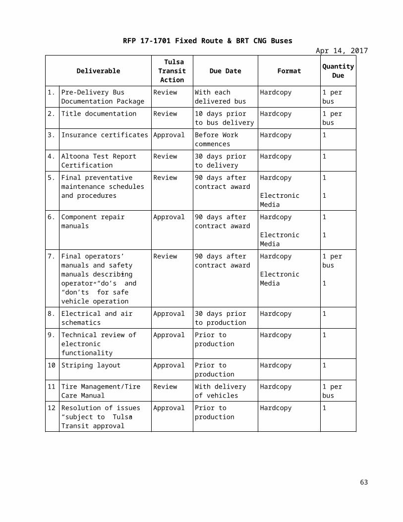
RFP 17-1701 Fixed Route & BRT CNG BusesApr 14, 2017
Thermally Activated Gas Relief Device. A relief device that is activated by high temperatures and generally contains a fusible material.
NOTE: Since this is a thermally activated device, it does not protect against over-pressure from improper charging practices.
Wheelchair. A mobility aid belonging to any class of three- or four-wheeled devices, usable indoors, designed for and used by individuals with mobility impairments, whether operated manually or powered. A “common wheelchair” is such a device that does not exceed 30 in. in width and 48 in. in length measured 2 in. above the ground, and does not weigh more than 600 lbs. when occupied.
TS 3. Referenced Publications The documents or portions thereof referenced within this specification shall be considered part of the requirements of the specification. The edition indicated for each referenced document is the current edition, as of the date of the APTA issuance of this specification.
TS 4. Legal Requirements The Contractor shall comply with all applicable federal, state and local regulations. These shall include but not be limited to ADA, as well as state and local accessibility, safety and security requirements. Local regulations are defined as those below the state level.
Buses shall meet all applicable FMVSS and shall accommodate all applicable FMCSR regulations in effect at location of Tulsa Transit and the date of manufacture.
In the event of any conflict between the requirements of these specifications and any applicable legal requirement, the legal requirement shall prevail. Technical requirements that exceed the legal requirements are not considered to conflict.
TS 5. Overall Requirements (a) The Contractor shall ensure the application and installation of major bus subcomponents and systems
are compliant with all such subcomponent vendors’ requirements and recommendations. Compo-nents used in the vehicle shall be of heavy-duty design and proven in transit service.
(b) The buses shall afford features essential for safe, efficient, and comfortable operation by the opera-tor. This implies the utmost in road and traffic visibility under all driving conditions and adequate means for safe passenger movement. The bus must be maneuvered easily in normal and heavy traffic.
(c) All Proposers must conform to these specifications and the product they furnish shall be of first-class quality and workmanship, and shall be of the best obtainable in the various trades. The design of the body, chassis, and equipment, which the manufacturer proposes to furnish, shall be such as to pro-duce a vehicle of substantial and durable construction in all respects.
(d) All systems, sub-systems, and components shall be individually and permanently labeled with Manu-facturer, Part Number, and Serial Number. Label is to be located, in each instance, for easiest access for reading while installed for use in the bus. List of all systems, subsystems, and components shall
63
RFP 17-1701 Fixed Route & BRT CNG BusesApr 14, 2017
accompany each bus either on paper or diskette. This shall include an OEM to vendor cross-reference listing.
(e) The manufacturer shall use FC-300 and FC-195 hoses for all flexible lines except A/C and discharge from the air compressor to the wet tank.
(f) The manufacturer shall be responsible for providing all parts or details which make each bus complete and ready for service, even though such part(s) or details(s) are not mentioned in these specifications.
(g) All buses shall be in compliance with the Americans with Disabilities Act (ADA). These buses shall be new, unused, current model specifically designed for intra-city service and substantially manufactured in the United States (in accordance with "Buy America" requirements). These units must meet all Federal requirements applicable to this type of vehicle.
(h) Buses provided under this contract shall be 30, 35, and 40 foot in length, 102 inches wide, with a low floor standard transit design.
TS 5.1 Worker and Protective Measuresa) All bolts or rods passing through wood shall be sealed with zinc chromate or other approved sealing
compound. Where wood and wood are placed together, all outer edges of wood, as well as the edges of holes, cutouts, and notches shall be coated with a linseed oil and titanium dioxide sealer or zinc chromate or other appropriate sealing compound.
b) All exterior light fixtures shall be fitted to the contour of the bus body and adequately sealed to prevent entrance of water.
c) All rubber seals on ventilator doors and compartment cabinet doors shall be placed in 'U' shaped channels to firmly hold the rubber in place. Equally, self-adhering closed cell neoprene seals may be used, without 'U' channels.
d) All burrs and sharp edges shall be dressed so as to prevent injury to passengers and employees, or damage to their clothing.
e) All buses shall be subjected to water tests simulating the severe rain conditions experienced in the Oklahoma environment. Windows, escape hatches, doors, etc. are subject to an approved water test to be conducted at the manufacturer’s facility by the manufacturer and shall be observed by the Resident Inspector(s).
64
RFP 17-1701 Fixed Route & BRT CNG BusesApr 14, 2017
f) Water testing may be verified by further testing at Tulsa Transit’s Maintenance Facility prior to the acceptance of each vehicle if test observation or verification of leak repair is missed on or not observed by the Resident Inspector on any bus built. Any bus that fails to pass the water test shall be corrected by the Contractor. The retest/corrective repair cycle shall repeat until the leak(s) have been eliminated to Tulsa Transit’s satisfaction.
TS 5.2 Water Test Descriptiona) The roof, roof hatches, front cap, rear cap, sidewalls, passenger windows, operator’s windows,
destination sign windows, windshields, wheel wells, and all doors of all buses shall be water tested prior to the delivery of each unit as follows:
1. The water test shall consist of a series of nozzles which are strategically located around the perimeter of the vehicle so as to spray water over the entire surface of the vehicle.
2. The nozzles shall eject a volume of water no less than 2.6 gallons per minute per nozzle under a pressure of no less than 22 lbs. per minute measured at the nozzle tip.
3. The Contractor shall be required to water test each vehicle under the conditions described above for no less than 15 minutes to ensure there are no water leaks in the bus.
4. Bus road testing shall be conducted immediately after the water test.
b) Contractor shall take the necessary steps of corrective action to repair any leaks found as a result of the described test and shall repeat the 15 minute water test to ensure that corrective steps have been successful. This process shall be repeated until no leaks are found. Documentation of each bus shall be kept by the manufacturer as to the location of the leak. What caused the leak to occur and shall describe the repair action taken to prevent the leak from reoccurring.
c) If the Contractor’s bus manufacturing process water test differs from the water test process and criteria described above, then any deviations shall be approved by Tulsa Transit.
TS 5.3 Total Bus Operation
a) Total bus operation shall be evaluated during road tests. The purpose of the road test is to observe and verify the operation of the bus as a system and to verify the functional operation of the subsys -tems that can be operated only while the bus is in motion. Each bus shall be driven for a minimum of twenty-five (25) miles during the road tests. The plan shall be submitted to Tulsa Transit for ap -proval.
b) All zerk grease testing fitting shall be accessible from a pit location with a standard straight nose grease fun.
c) All vehicles will be road-tested and dyno-tested.
65
RFP 17-1701 Fixed Route & BRT CNG BusesApr 14, 2017
TS 5.4 Weighta) It shall be a design goal to construct each bus as light in weight as possible without degradation of
safety, appearance, comfort, traction, or performance.
b) Buses at a capacity load shall not exceed the tire factor limits, brake test criteria, or structural design criteria.
TS 5.5 Capacity The vehicle shall be designed to carry the gross vehicle weight, which shall not exceed the bus GVWR.
TS 5.6 Service Life The minimum useful design life of the bus in transit service shall be at least twelve (12) years or 500,000 miles. It shall be capable of operating at least 40,000 miles per year, including the twelfth year.
TS 5.7 Maintenance and Inspection a) Scheduled maintenance tasks shall be related and shall be, in accordance with the manufacturer’s
recommended preventative maintenance schedule (along with routine daily service performed during the fueling operations).
b) Test ports, as required, shall be provided for commonly checked functions on the bus, such as air intake, exhaust, hydraulic, pneumatic, charge-air and engine cooling systems, engine, transmission, etc.
c) All engine and transmission components will have the fluid sampling valves (or equivalents) installed that are easy to access: device and location selection to be made at pre-production meeting.
d) The coach manufacturer shall give prime consideration to the routine problems of maintaining the vehicle. All coach components and systems, both mechanical and electrical, which will require periodic physical Work or inspection processes, shall be installed so that a minimum of time is consumed in gaining access to the critical repair areas. It shall not be necessary to disassemble portions of the coach structure and/or equipment such as seats and flooring under seats in order to gain access to these areas. Each coach shall be designed to facilitate the disassembly, reassembly, servicing or maintenance, using tools and equipment that are normally available as standard commercial items.
e) Requirements for the use of unique specialized tools will be minimized. The body and structure of the coach shall be designed for ease of maintenance and repair. Individual panels or other equipment which may be damaged in normal service shall be repairable or replaceable. Ease of repair shall be related to the vulnerability of the item to damage in service.
f) Contractor shall provide a list of all special tools and pricing required for maintaining this equipment. Said list shall be submitted as a supplement to the Pricing Schedule.
NOTE: Tools such as compartments door keys and other tools that are required for daily maintenance and inspections shall not be included in the special tool list and shall be furnished for each coach.
66
RFP 17-1701 Fixed Route & BRT CNG BusesApr 14, 2017
TS 5.8 Interchangeabilitya) Unless otherwise agreed, all units and components procured under this Contract, whether provided
by Suppliers or manufactured by the Contractor, shall be duplicates in design, manufacture and installation to ensure interchangeability among buses in each order group in this procurement. This interchangeability shall extend to the individual components as well as to their locations in the buses. These components shall include, but are not limited to, passenger window hardware, interior trim, lamps, lamp lenses and seat assemblies. Components with non-identical functions shall not be, or appear to be, interchangeable.
b) Any one component or unit used in the construction of these buses shall be an exact duplicate in design, manufacture and assembly for each bus in each order group in this Contract. Contractor shall identify and secure approval for any changes in components or unit construction provided within a Contract.
c) In the event that the Contractor is unable to comply with the interchangeability requirement, the Contractor must notify Tulsa Transit and obtain Tulsa Transit’s prior written approval, including any changing in pricing.
d) Tulsa Transit shall review proposed product changes on a case-by-case basis and shall have the right to require extended warranties to ensure that product changes perform as least as well as the originally supplied products.
TS 5.9 Traininga) Along with the purchase of new buses, it is Tulsa Transit’s requirements to have the manufacturer
provide an appropriate program of instruction targeted to the operator, servicing, and maintenance personnel. This will be accomplished through a combination of Agency on-site and Contractor and/or supplier site training.
b) All training instructors shall be competent to teach the course area they are instructing. Further, all instructors shall speak English and have a complete understanding of the English language. If the in-structor or vendor presenter lacks the skill or knowledge to provide instruction, or cannot communi -cate with the students, Tulsa Transit reserves the right to request that the instructor be replaced and the area of training be repeated.
TS 5.10 Operator OrientationThe Contractor shall provide an 8-hour course of instruction for the agency’s Operations personnel. Class size is not to exceed 10 employees per session. The program shall include, but not be limited to the follow-ing:
Operator Compartment Controls and Switches Warning Indicators and Gauges Seat Adjustment Door Control Walk Around Inspection Compartment-by-Compartment Explanation
67
RFP 17-1701 Fixed Route & BRT CNG BusesApr 14, 2017
Mirror Adjustments Climate Control System Wheelchair Ramp Safety Equipment Emergency Procedures Wheelchairs Securement
TS 5.11 Maintenance OrientationThe Contractor shall provide an 8-hour course of instruction for the agency’s Maintenance personnel on Ve-hicle Servicing. Class size is not to exceed 10 employees per session. At minimum, the course shall cover the following areas:
Chassis Suspension Steering Axles Brakes Air Body Doors Electrical Engine Fuel Transmission HVAC Fire Suppression Towing/Jacking
TS 5.12 Technical Traininga) The Contractor shall provide a structured program of technical training which will consist of specific
and identifiably separate curriculum for each subject area. Each subject area training session shall be between eight (8) and forty (40) classroom/hands=on hours based on subject area, with class being no more than (10) participants. The training will be delivered at Tulsa Transit’s location on a sched-ule coordinated by Tulsa Transit’s training department and the Contractor. For the buses purchased by CART, the training will be delivered at CART locations on a schedule coordinated by the CART training department and the Contractor.
b) The following subject areas will be offered:
Body and Chassis Suspension and Steering Electrical and Electronics Air and Brake System HVAC/Climate Controls Engine Transmission Wheelchair Ramp System
68
RFP 17-1701 Fixed Route & BRT CNG BusesApr 14, 2017
Destination Signs Doors Axles and Tires CNG Fuel System Fire Suppression
c) The technical training shall be delivered on a schedule coordinated between Tulsa Transit’s training department and the Contractor. The subject area of sessions to be provided will be negotiated between Tulsa Transit’s training personnel and the Contractor, with the base requirement being 96 hours.
TS 5.13 OEMThe Contractor shall provide two (2) class slots at the manufacturer’s suppliers training facility for technical instruction course on the operation, diagnostics, troubleshooting, repair, and servicing of the below listed areas:
a) Engineb) Transmission
TS 5.14 Operating Environment
The bus shall achieve normal operation in ambient temperature ranges of 10 ºF to 115 ºF, at relative humidity between 5 percent and 100 percent, and at altitudes up to 3000 feet above sea level. Degradation of performance due to atmospheric conditions shall be minimized at temperatures below 10 °F, above 115 °F or at altitudes above 3000 feet. Altitude requirements above 3000 feet will need separate discussions with the engine manufacturer to ensure that performance requirements are not compromised. Speed, gradability and acceleration performance requirements shall be met at, or corrected to, 77 °F, 29.31 in. Hg, dry air per SAE J1995.
TS 5.15 NoiseInterior NoiseThe combination of inner and outer panels and any material used between them shall provide sufficient sound insulation so that a sound source with a level of 83 dBA measured at the outside skin of the bus shall have a sound level of 65 dBA or less at any point inside the bus. These conditions shall prevail with all openings, including doors and windows, closed and with the engine and accessories switched off.
The bus-generated noise level experienced by a passenger at any seat location in the bus shall not exceed 80 dBA. The operator area shall not experience a noise level of more than 75.5 dBA.
An exception shall be made for the turntable area, which shall be considered a separate environment.
Exterior NoiseAirborne noise generated by the bus and measured from either side shall not exceed 80 dBA under full power acceleration when operated 0 to 35 mph at curb weight. The maximum noise level generated by the bus pulling away from a stop at full power shall not exceed 83 dBA. The bus-generated noise at curb idle shall not exceed 65 dBA. If the noise contains an audible discrete frequency, a penalty of 5 dBA shall be added to the sound level measured.
69
RFP 17-1701 Fixed Route & BRT CNG BusesApr 14, 2017
All noise readings shall be taken fifty (50) feet from, and perpendicular to, the centerline of the bus with all accessories operating. The Contractor shall comply with the exterior noise requirements defined in local laws and ordinances identified by Tulsa Transit and SAE J366.
TS 5.16 Fire Safety The bus shall be designed and manufactured in accordance with all applicable fire safety and smoke emission regulations. These provisions shall include the use of fire-retardant/low-smoke materials, bulkheads and facilitation of passenger evacuation.
All materials used in the construction of the passenger compartment of the bus shall be in accordance with the Recommended Fire Safety Practices defined in FMVSS 302, dated October 20, 1993. Materials entirely enclosed from the passenger compartment, such as insulation within the sidewalls and sub-floor, need not comply. In addition, smaller components and items, such as seat grab rails, switch knobs, and small light lenses shall be exempt from this requirement. A minimum 5lb. 2A 10 BC rating fire extinguisher shall be furnished and mounted in each vehicle.
TS 5.17 Recycled Products - Respect for the EnvironmentIn the design and manufacture of the bus, the Contractor shall make every effort to reduce the amount of potentially hazardous waste. In accordance with Section 6002 of the Resource Conservation and Recovery Act, the Contractor shall use, whenever possible and allowed by the specifications, recycled materials in the manufacture of the bus.
BUS DIMENSIONSTS 6. Physical SizeWith exceptions such as exterior mirrors, marker and signal lights, bumpers, fender skirts, washers, wipers, ad frames, cameras, object detection systems, bicycle racks, feelers and rub rails, the bus shall have the following overall dimensions at static conditions and design height.
TS 6.1 Bus LengthFor ease of use, the following tolerances will be allowable for each given bus length. Bus length is determined as the measurement from bumper to bumper.
Vehicle Length: 30 Foot Bus (29’ to 34’ 11”)35 Foot Bus (35’ to 39’ 11”)40 Foot Bus (40’ to 44’ 11”)40 Foot BRT Bus (40’ to 44’ 11”)
TS 6.2 Bus WidthBody width shall be maximum 102 inches (+0/- 1 inch), excluding wheel wells and bumpers.
70
RFP 17-1701 Fixed Route & BRT CNG BusesApr 14, 2017
TS 6.3 Bus HeightMaximum vehicle height shall be 140 inches, including all rigid, roof-mounted items..
TS 6.4 Step HeightThe step height shall not exceed 15.5 inches at doorway without kneeling. A maximum of two steps is allowed to accommodate a raised aisle floor in the rear of the bus.
TS 6.5 Underbody ClearanceThe bus shall maintain the minimum clearance dimensions as defined in SAE Standard J689, regardless of load up to the gross vehicle weight rating.
As an option a front skid plate for ramp and front undercarriage protection will be made available and priced separately.
TS 6.6 Ramp ClearancesThe approach angle is the angle measured between a line tangent to the front tire static loaded radius arc and the initial point of structural interference forward of the front tire to the ground.
The departure angle is the angle measured between a line tangent to the rear tire static loaded radius arc and the initial point of structural interference rearward of the rear tire to the ground.
The Breakover angle is the angle measured between two lines tangent to the front and rear tire static loaded radius and intersecting at a point on the underside of the vehicle that defines the largest ramp over which the vehicle can roll.
TABLE 1Breakover Angle
Angle 30 to 40 foot BusApproach 8.6 degrees (min)Front Breakover 8 degrees (min)Departure 8.1 degrees (min)
TS 6.7 Ground ClearanceGround clearance shall be no less than 9 in., (8 in. at jacking pad) except within the axle zone and wheel area.
Axle zone clearance, which is the projected area between tires and wheels on the same axial centerline, shall be no less than 5.4 in.
Wheel area clearance shall be no less than 8 in. for parts fixed to the bus body and 6 in. for parts that move vertically with the axles.
71
RFP 17-1701 Fixed Route & BRT CNG BusesApr 14, 2017
TS 6.8 Floor HeightHeight of the step above the street shall be no more than 16 inches measured at the centerline of the front and rear doorway.
The floor may be inclined along the longitudinal axis of the bus, and the incline shall not exceed 3.5 degrees off the horizontal except locally at the doors where 2 degree slope toward the door is allowed.
All floor measurements shall be with the bus at the design running height and on a level surface and with the standard installed tires.
A maximum of two steps is allowed to accommodate a raised aisle floor in the rear of the bus.
TS 6.9 Interior Headroom Headroom above the aisle and at the centerline of the aisle seats shall be no less than 78 inches in the forward half of the bus tapering to no less than 74 inches forward of the rear settee.
At the centerline of the window seats, headroom shall be no lower than 65 inches, except for parcel racks and reading lights, if specified.
Headroom at the back of the rear bench seat may be reduced to a minimum of 56 inches, but it shall increase to the ceiling height at the front of the seat cushion.
In any area of the bus directly over the head of a seated passenger and positioned where a passenger entering or leaving the seat is prone to strike his or her head, padding shall be provided on the overhead paneling.
TS 6.10 Aisle WidthThe minimum clear aisle width between pairs of transverse seats with all attached hardware shall be at least 22 in.
The aisle width between the front wheelhouses shall be at least 35.5 inches, and the entire area between the front wheelhouses shall be available for passengers and mobility aid devices,
VEHICLE PERFORMANCE TS 7. Power Requirements The propulsion system shall be sized to provide sufficient power to enable the bus to meet the defined acceleration, top speed, and gradability requirements, and operate all propulsion-driven accessories using actual road test results and computerized vehicle performance data.
TS 7.1 Top Speed The bus shall be capable of achieving a top speed of 65 mph on a straight, level road at GVWR with all accessories operating. The bus shall be capable of safely maintaining the vehicle speed according to the recommendations by the tire manufacturer.
72
RFP 17-1701 Fixed Route & BRT CNG BusesApr 14, 2017
NOTE: Values are assumed to be sustained. Manufacturer shall supply Tulsa Transit with data if there is a variance between peak performance and sustained vehicle performance.
TS 7.2 Gradability Gradability requirements shall be met on grades with a dry commercial asphalt or concrete pavement at GVWR with all accessories operating.
The propulsion system and drivetrain shall enable the bus to achieve and maintain a speed of 40 mph on a 2 ½ percent ascending grade and 15 mph on a 10 percent ascending grade continuous.
NOTE: Values are assumed to be sustained. Manufacturer shall supply Tulsa Transit with data if there is a variance between peak performance and sustained vehicle performance.
TS 7.3 Acceleration The acceleration shall meet the requirements below and shall be sufficiently gradual and smooth to prevent throwing standing passengers off-balance. Acceleration measurement shall commence when the accelerator is depressed.
TABLE 2Maximum Start Acceleration Times on a Level Surface1
Speed (mph) Maximum time(seconds)
10 520 1030 1840 3050 60
Top speedVehicle weight = GVWR
Maximum Start Acceleration Times on a Level Surface
73
RFP 17-1701 Fixed Route & BRT CNG BusesApr 14, 2017
TS 7.4 Operating Range The operating range of the coach shall be designed to meet the operating profile as stated in the “Design Operating Profile” section.
TS 7.5 Compressed Natural Gas (CNG)The operating range of the coach when run on the Altoona Test cycle shall be at least 350 miles with an initial gas settled pressure of 3600 psi at 70˚ F..
TS 7.6 Fuel EconomyTest results from the Altoona fuel economy tests or other applicable test procedures shall be provided to the Tulsa Transit. Results shall include vehicle configuration and test environment information. Fuel economy data shall be provided for each design operating profile. The design operating profile is assumed to be defined by the Altoona fuel duty cycle. Tulsa Transit will provide a percentage of each duty cycle that is representative of Tulsa Transit’s service.
POWERPLANTTS 8. Engine - CNGThe bus shall be powered by a Cummins ISLG 280 HP CNG engine capable of providing the performance to satisfy the operating conditions in geographical areas throughout the state of Oklahoma. The engine shall have a minimum design life of 12 years or 500,000 miles, whichever comes first, and it shall be designed to require no more than one (1) major overhaul to achieve this lifetime. The engine and the transmission shall be compatible with each other in that the electronic controls of the engine shall interface with the transmission and vice versa, if controls are used. Engine shall meet all current Federal EPA requirements. A copy of the engine certification shall be supplied with the proposal.
The engine shall comply with applicable local, state, and/or federal emissions and useful life requirements. Components of the fuel management and/or control system shall have a design life of not less than 150,000 miles without replacement or major service. The lifetime estimate is based on the design operating profile.
The engine shall be equipped with an electronically controlled management system, compatible with either 12- or 24- volt power distribution. The engine control system shall be capable of transmitting and receiving electronic inputs and data from other drivetrain components and broadcasting that data to other vehicle systems. Communication between electronic drivetrain components and other vehicle systems shall be made using the communications networks. The engine’s electronic management system shall monitor operating conditions and provide instantaneous adjustments to optimize both engine and bus performance. The system shall be programmable to allow optimization of programmable features.
The engine starting system shall be protected by an interlock that prevents its engagement when the engine is running. Special equipment or procedures may be employed to start the bus when exposed to temperatures less than 30 °F for a minimum of four hours without the engine in operation. All cold weather starting aids, engine heating devices and procedures shall be of the type recommended by the engine manufacturer and approved by Tulsa Transit. The integration of all systems on the vehicle relative to engine idle speed shall be the responsibility of the vehicle manufacturer to meet the requirements of the transit property. A 120 volt @ 100 watt engine block heater will be located in the rear engine compartment.
74
RFP 17-1701 Fixed Route & BRT CNG BusesApr 14, 2017
The engine control system shall protect the engine against progressive damage. The system shall monitor conditions critical for safe operation and automatically derate power and/or speed and initiate engine shutdown as needed. Engine shall be a minimum 6.0 liter gasoline V8 or approved equal.
The engine compartment shall be insulated from the passenger compartment with fiberglass/foil blanket material or equivalent to minimize coach interior noise level, heat, and fumes. Under no conditions is interior noise level to exceed 83 dBA.
TS 8.1 Automatic Engine Protection/Shutdown Override Feature1) The engine control system shall protect the engine against progressive damage. The system shall
monitor conditions critical for safe operation and automatically de-rate power and/or speed and ini -tiate engine shutdown as needed. The on-board diagnostic system shall trigger an audible alarm and warning light to signal the operator when the engine control unit detects a malfunction and the en-gine protection system is activated.
2) Automatic shutdown shall occur when parameters established for the functions below are ex-ceeded:
a. Coolant Levelb. Coolant Temperaturec. Oil Pressured. Oil Temperaturee. 20 minutes of idlingf. Exhaust Temperatureg. Fire Suppression
3) The automatic shutdown for the Fire Suppression feature shall occur when the Fire Suppression sys -tem is discharged
4) A control shall be available to the operator, to allow temporary override (30-45 seconds) of the en-gine protection/shutdown system if engine power is required to move the bus in emergency condi -tions. Override action shall be recorded. This data shall be retrievable by Tulsa Transit.
5) The fast idle device shall be activated and controlled automatically by the engine control system. This device will operate only when the transmission is in neutral.
6) The integration of all systems on the vehicle relative to engine idle speed shall be the responsibility of the vehicle manufacturer and shall meet the requirements of the transit property.
7) The engine starting system shall be protected by an interlock that prevents its engagement when the engine is running.
8) Engine throttle operation shall be inhibited, through interlocks, whenever:
a. Front or rear door openb. The vehicle is kneeledc. Wheelchair ramp is in operation
75
RFP 17-1701 Fixed Route & BRT CNG BusesApr 14, 2017
d. Rear door emergency releasee. Fast Idle Operation
9) Failure of the engine throttle control shall not result in an unsafe condition. Loss of air or electrical throttle control shall inhibit throttle.
10) A rear mounted engine speed control (hand throttle) will be provided.
11) The engine shall have on-board diagnostic capabilities, able to monitor vital functions, store out-of-parameter conditions in memory, and communicate faults and vital conditions to service personnel. Diagnostic reader device connector ports, suitable protected against dirt and moisture, shall be pro -vided in operator’s area and near or inside engine compartment. The onboard diagnostic system shll inform the operator via visual and/or audible alarms when out-of-parameter conditions exist for vi -tal engine functions. All removable caps shall be tethered including the caps for the diagnostic con -nector ports in the operator/s area and in the engine compartment.
TS 8.2 Engine – CNGA Cummins ISL-G engine meeting all regulatory requirements when operating on fuel equal to CARB Specifi-cations for Compressed Natural Gas #2292.5 will be provided. The four predominant characteristics that must be met are Methane, Ethane, Butane, and Propane.TS 8.3 Propulsion System ServiceThe propulsion system shall be arranged so that accessibility for all routine maintenance is assured. No spe-cial tools, other than dollies and hoists, shall be required to remove the propulsion system or any subsys-tems. However, Tulsa Transit shall recognize that properly rated test equipment and safe electrical work practices are essential when servicing high voltage hybrid components. The exhaust system, air cleaner, air compressor, starter (if used), alternator, radiator, all engine accessories, and any other component requiring service or replacement shall be easily removable.
TS 8.4 Standard Requirements for a Fast Idle DeviceThe fast idle device shall be activated and controlled automatically by the control system.
TS 9. Cooling SystemsThe cooling systems shall be of sufficient size to maintain all engine and transmission fluids and engine intake air at safe, continuous operating temperatures during the most severe operations possible and in accordance with engine and transmission manufacturers’ cooling system requirements. The cooling system fan controls should sense the temperatures of the operating fluids and the intake air, and if either is above safe operating conditions the cooling fan should be engaged. The fan control system shall be designed with a fail-safe mode of “fan on.” The cooling system shall meet the requirements stated in the operating environment.
76
RFP 17-1701 Fixed Route & BRT CNG BusesApr 14, 2017
The engine shall be cooled by a water-based, pressure type, cooling system that does not permit boiling or coolant loss during the operations described above. Engine thermostats shall be easily accessible for replacement. Shutoff valves shall allow filter replacement without coolant loss. Valves shall permit complete shutoff of lines for the heating and defroster units, and water booster pumps. The water boost pump shall be a long life brushless design. All low points in the water-based cooling system shall be equipped with a standard with a 1/4" MPT brass hex plug. Air vent valves shall be fitted at high points in the cooling system unless it can be demonstrated that the system is self-purging.
An EMP E-Fan electric fan system will be provided. Electric fans shall be brushless, variable speed, reversible and have a corrosion resistant metal shroud with finger guards that meet SAE spec J1308_200808. The fans should provide electronic feedback control and have diagnostics capability through the standard SAE J1939 diagnostics port. The cooling system shall consist of multiple electric DC brushless pusher type variable speed fans with electronic feedback controls. Electric fan motor speeds shall have a minimum operating range of 0-5500 rpm with capability of manual or automatic reverse operation in order to assist in debris re-moval. The cooling system shall be equipped with a master controller with the following capabilities; auto-matically reduce fan speed when the vehicle stops to minimize noise.
A means of determining satisfactory engine coolant level shall be provided. A spring-loaded, push-button type valve or lever shall be provided to safely release pressure or vacuum in the cooling system with both it and the water filler no more than +/- 60 inches above the ground. Radiator and charge air cooler fan(s) shall be electrically driven and capable of a manual reverse operations for periodic self-cleaning of the radiator and charge air cooler.
TS 9.1 Charge Air CoolingThe charge air cooling system also referred to as after-coolers or inter-coolers shall provide maximum air in-take temperature reduction with minimal pressure loss. The charge air radiator shall be sized and posi-tioned to meet engine manufacturer’s requirements. The charge air radiator shall not be stacked ahead of or behind the engine radiator and shall be positioned as close to the engine as possible unless integrated with the radiator. Air ducting and fittings shall be protected against heat sources and shall be configured to minimize restrictions and maintain sealing integrity.
TS 9.2 Transmission CoolingThe transmission shall be cooled by a dedicated heat exchanger sized to maintain operating fluid within the transmission manufacturer’s recommended parameters of flow, pressure and temperature. The transmission cooling system shall be matched to retarder and engine cooling systems to ensure that all operating fluids remain within recommended temperature limits established by each component manufacturer. The engine cooling system should provide coolant bypass flow to the transmission cooling system with the engine thermostats closed.
TS 10. Transmission (Conventional Powertrain)(1) The transmission shall be a Voith 864.6 automatic shift with torque converter, retarder, and electronic controls. Gross input power, gross input torque and rated input speed shall be compatible with the engine. The transmission shall be designed to operate for not less than 300,000 miles on the design operating profile without replacement or major service. The transmission should be easily removable without disturbing the engine and accessible for service.
77
RFP 17-1701 Fixed Route & BRT CNG BusesApr 14, 2017
As an option, the Allison B 400 R transmission will be made available and priced separately.
The electronic controls shall be capable of transmitting and receiving electronic inputs and data from other drivetrain components and broadcasting that data to other vehicle systems. Communication between electronic drivetrain components and other vehicle systems shall be made using the communications networks. Electronic controls shall be compatible with either 12- or 24- volt power distribution, provide consistent shift quality, and compensate for changing conditions such as variations in vehicle weight and engine power.
A nominal brake pedal application of 6 to 10 psi shall be required by the operator to engage forward or reverse range from the neutral position to prevent sudden acceleration of the bus from a parked position.
The electronically controlled transmission shall have on-board diagnostic capabilities, be able to monitor functions, store and time stamp out-of-parameter conditions in memory, and communicate faults and vital conditions to service personnel. The transmission shall contain built-in protection software to guard against severe damage. The on-board diagnostic system shall trigger a visual alarm to the operator when the electronic control unit detects a malfunction.
As an option, an electronic transmission fluid level monitoring and protection system will be made available and priced separately.
Models with remote mounted transmission vents shall have vents mounted to prevent plugging and/or the entry of foreign materials.
TS 10.1 Retarder(1) The powertrain shall be equipped with a retarder designed to extend brake lining service life. The application of the retarder shall cause a smooth blending of both retarder and service brake function and shall not activate the brake lights.
(2) Actuation of ABS and/or automatic traction control (ATC) shall override the operation of the brake retarder.
TS 10.2 Standard Requirement for Retarder ActivationThe retarder shall be adjustable within the limits of the powertrain and activated when the brake pedal is depressed. Tulsa Transit will work with the OEM/drive system manufacturer to determine retarder perfor-mance settings. A retarder disable switch shall be accessible to the seated operator. Disabling retarder shall be recorded for Agency data collection.
TS 10.3 MountingAll powerplant mounting shall be mechanically isolated to minimize transfer of vibration to the body struc-ture and provide a minimum clearance of 0.75 inches. Mounts shall control the movement of the power-plant so as not to affect performance of belt-driven accessories or cause strain in piping and wiring connec-tions to the powerplant.
78
RFP 17-1701 Fixed Route & BRT CNG BusesApr 14, 2017
TS 10.4 Engine/Transmission Oil Fill/FiltersEngine oil and the radiator filler caps shall be hinged to the filler neck and closed with spring pressure or positive locks to prevent leakage. All fluid fill locations shall be properly labeled to help ensure that correct fluid is added. All fillers shall be easily accessible with standard funnels, pour spouts, and automatic dispens-ing equipment. All lubricant sumps shall be fitted with magnetic-type drain plugs. The engine and transmis-sion shall be equipped with sufficient heavy-duty fuel and oil filters for efficient operation and to protect the engine and transmission between scheduled filter changes. All filters shall be easily accessible and the filter bases shall be plumbed to ensure correct reinstallation. A Spinner II Model 576HE with FC300 hose shall be provided as an auxiliary filter.
As an option, the FEMCO oil drain will be made available and priced separately.
TS 10.5 Engine Compartment GuagesEngine oil pressure, transmission, and coolant temperature gauges are required in engine compartment.
TS 10.6 Engine Air CleanerAn air cleaner with a dry filter element and a graduated air filter restriction indicator shall be provided. The location of the air intake system shall be designed to minimize the entry of dust and debris and to maximize the life of the air filter. The engine air duct shall be designed to minimize the entry of water into the air in-take system. Drainage provisions shall be included to allow any water/moisture to drain prior to entry into air filter.
TS 10.7 Hydraulic SystemsHydraulic system service tasks shall be minimized and scheduled no more frequently than those of other major bus systems. All elements of the hydraulic system shall be easily accessible for service or unit replace-ment. Critical points in the hydraulic system shall be fitted with service ports so that portable diagnostic equipment may be connected or sensors for an off-board diagnostic system permanently attached to moni-tor system operation when applicable. A tamper-proof priority system shall prevent the loss of power steer-ing during operation of the bus if other devices are also powered by the hydraulic system.
The hydraulic system shall operate within the allowable temperature range as specified by the lubricant manufacturer.
TS 10.8 Fluid LinesAll lines shall be rigidly supported to prevent chafing damage, fatigue failures, degradation, and tension strain. Lines should be sufficiently flexible to minimize mechanical loads on the components. Lines passing through a panel, frame, or bulkhead shall be protected by grommets (or similar devices) that fit snugly to both the line and the perimeter of the hole that the line passes through to prevent chafing and wear. Pipes and fluid hoses shall not be bundled with or used to support electrical wire harnesses.
Lines shall be as short as practicable and shall be routed or shielded so that failure of a line shall not allow the contents to spray or drain onto any component operable above the auto-ignition temperature of the fluid.
All hoses, pipes, lines, and fittings shall be specified and installed per the manufacturer’s recommendations.
79
RFP 17-1701 Fixed Route & BRT CNG BusesApr 14, 2017
TS 10.9 Fittings and ClampsAll clamps shall maintain a constant tension at all times, expanding and contracting with the line in response to temperature changes and aging of the line material. The lines shall be designed for use in the environ-ment where they are installed. For example, high-temperature resistant in the engine compartment, resis-tant to road salts near the road surface, etc.
Compression fittings shall be standardized to prevent the intermixing of components. Compression fitting components from more than one manufacturer shall not be mixed, even if the components are known to be interchangeable.
TS 10.10 Charge Air PipingCharge air piping and fittings shall be designed to minimize air restrictions and leaks. Piping shall be as short as possible, and the number of bends shall be minimized. Bend radii shall be maximized to meet the pres-sure drop and temperature rise requirements of the engine manufacturer. The cross-section of all charge air piping shall not be less than the cross-section of the intake manifold inlet. Any changes in pipe diameter shall be gradual to ensure a smooth passage of air and to minimize restrictions. Piping shall be routed away from heat sources as practicable and shielded as required to meet the temperature rise requirements of the engine manufacturer.
Charge air piping shall be constructed of stainless steel, aluminized steel, or anodized aluminum, except be-tween the air filter and turbocharger inlet, where piping may be constructed of fiberglass. Connections be-tween all charge air piping sections shall be sealed with a short section of reinforced hose and secured with stainless steel constant tension clamps that provide a complete 360-degree seal.
TS 10.11 RadiatorRadiator piping shall be stainless steel or brass tubing, and if practicable, hoses shall be eliminated. Neces-sary hoses shall be impervious to all bus fluids. All hoses shall be secured with stainless steel clamps that provide a complete 360-degree seal. The clamps shall maintain a constant tension at all times, expanding and contracting with the hose in response to temperature changes and aging of the hose material.
TS 10.12 Oil & Hydraulic LinesOil and hydraulic lines shall be compatible with the substances they carry. The lines shall be designed and in-tended for use in the environment where they are installed. For example, high–temperature resistant in the engine compartment, resistant to road salts near the road surface, etc. Lines within the engine compart-ment shall be composed of steel tubing where practicable, except in locations where flexible lines are re-quired.
TS 11. Fuel TS 11.1 Fuel LinesFuel lines shall be securely mounted, braced and supported as designed by the bus manufacturer to minimize vibration and chafing and shall be protected against damage, corrosion or breakage due to strain or wear.
Manifolds connecting fuel containers shall be designed and fabricated to minimize vibration and shall be installed in protected locations to prevent line or manifold damage from unsecured objects or road debris.
80
RFP 17-1701 Fixed Route & BRT CNG BusesApr 14, 2017
Fuel hose and hose connections, where permitted, shall be made from materials resistant to corrosion and fuel and protected from fretting and high heat. Fuel hoses shall be accessible for ease of serviceability.
TS 11.2 Fuel Lines – CNGFuel lines shall comply with NFPA-52. All tubing shall be a minimum of seamless stainless steel (ASTM A269 or equivalent). Fuel lines and fittings shall not be fabricated from cast iron, galvanized pipe, aluminum, plas-tic, or copper alloy with content exceeding 70 percent copper. Pipe fittings and hoses shall be clear and free from cuttings, burrs, or scale. Pipe thread joining material that is impervious to CNG shall be utilized as re-quired. Fuel lines shall be identifiable as fuel lines only.
High-pressure CNG lines shall be pressure tested to 3600 psi pressure prior to fueling. CNG, nitrogen or clean, dry air shall be used to pressure test the lines/assembly. The bus manufacturer shall have a docu-mented procedure for testing the high pressure line assembly.
Fuel lines shall be securely mounted, braced, and supported using “split-block” type or stainless steel P-clamps; all mounting clamps shall be mounted to a rigid structure to minimize vibration and shall be pro-tected against damage, corrosion, or breakage due to strain, rubbing, or wear. “Floating clamps” (not mounted to a rigid structure) shall not be permitted. Fuel lines shall not be used to secure other compo-nents (wires, air lines, etc.).
Manifolds connecting fuel containers shall be designed and fabricated to minimize vibration and shall be in-stalled in protected location(s) to prevent line or manifold damage from unsecured objects or road debris.
Fuel hose connections, where possible, shall be less than 60 inches in length, made from materials resistant to corrosion and action of natural gas, and protected from fretting and high heat and shall be supported ap-proximately every 12 inches.
TS 12. Design & ConstructionTS 12.1 LabelingThe capacity, date of manufacture, manufacturer name, location of manufacture, and certification of com-pliance to Federal Motor Carrier Safety Regulation shall be permanently marked on the fuel tank(s). The markings shall be readily visible and shall not be covered with an undercoating material.
TS 12.2 Fuel FillerThe fuel filler shall be located behind the engine bulkhead on the curbside of the bus. There should be no fuel lines in front of the engine bulkhead.
TS 13. Design & Construction - CNGTS 13.1 Fuel Containers/Cylinders
1) CNG fuel containers/cylinders must be designed, constructed, manufactured, and tested in accordance with at least one of the following:
a. NFPA 52-Standard for Compressed Natural Gas (CNG)b. Vehicular Fuel Systems FMVSS 304c. Any local standard(s) specifically intended for CNG fuel containers
81
RFP 17-1701 Fixed Route & BRT CNG BusesApr 14, 2017
2) The design and construction of the fuel system supplied by the OEM shall comply with fed-eral and local regulations.
TS 13.2 Installation1) Fuel cylinders shall be installed in accordance with ANSI/IAS NGV2 - 1998, Basic Requirements for
Compressed Natural Gas Vehicles (NGV) Fuel Containers and NFPA 52, Compressed Natural Gas (CNG) Vehicular Fuel Systems Code, 1998 edition Section 303. The placement of tanks shall be lim-ited to the roof of the vehicle.
2) Fuel cylinders, attached valves, pressure relief devices, and mounting brackets should be installed and protected so their operation is not affected by bus washers and environmental agents such as rain, snow, ice, or mud. These components should be protected from significant damage caused by debris or collision.
3) For safety purposes, the roof mounted tanks must be accessible to maintenance personnel without the requirement to walk on top of the closed tank enclosure to open the enclosure doors. The enclo-sure doors shall be secured with non-keyed twist latches and shall incorporate hand holds to assist in opening the enclosure doors once unlatched. When opened, the enclosure doors shall be secured to prevent from over-extension. The open enclosure doors shall also provide a certain degree of fall prevention. Once the tanks are exposed, for safety purposes, access should be provided in the mid-dle of the roof line without having to walk on top of or over the tanks in order to inspect or service the tanks, valves, regulators, or Pressure Relief Devices (PRD). This access shall be constructed in a manner that avoids the need to walk on the actual roof covering. Access to the roof mounted tanks shall be through the rear roof hatch.
4) CNG fueled buses shall be equipped with an active automatic gas detection system which shall an-nunciate unsafe levels of methane. The automatic gas detection system shall be integrated with an onboard fire suppression system.
TS 13.3 LabelingCNG fuel systems shall be labeled in accordance with NFPA 52, “Compressed Natural Gas (CNG) Vehicular fuel Systems Code,” 1998 edition.
TS 13.4 Pressure Relief Devices (PRDs)PRDs must be designed, constructed, manufactured, and tested in accordance with ANIS/IAS PRD1 - 1998, “Pressure Relief Devices for Natural Gas Vehicle (NGV) Fuel Containers” and ANSI/IAS NGV2- 1998, “Basic Requirements for Compressed Natural Gas Vehicle (NGV) Fuel Containers.” All natural gas fuel system pip-ing, including the PRD vent line, shall be stainless steel. All PRDs must be vented to outside.
TS 13.5 ValvesValves must be installed in accordance with ANIS/IAS NGV2 - 1998, “Basic Requirements for Compressed Natural Gas Vehicle (NGV) Fuel Containers” and NFPA 52, “Standard for Compressed Natural Gas (CNG) Ve-hicular Fuel Systems.”
82
RFP 17-1701 Fixed Route & BRT CNG BusesApr 14, 2017
TS 13.6 Fuel FillerThe fuel filler shall be located behind the engine bulkhead on the curbside of the bus. The filler cap shall be retained to prevent loss and shall be recessed into the body.
The fill and vent receptacles shall be located within an enclosure on the right side of the bus. The access door shall be sized to allow full viewing of gauges, ease of hookups, and maneuver of fuel nozzle.
The fuel fill receptacle and vent receptacle attachment shall be robust and capable of routine fueling con-nects/disconnects without deflection or metal fatigue, and capable of withstanding mechanical loads in-duced by a fueling drive away incident without attachment failure.
TS 13.7 Fueling SystemThe CNG fueling port receptacle shall be an ANSI/AGA NGV1 or NGV2 certified receptacle as designated by Tulsa Transit. The bus shall be capable of being fueled by a nozzle determined by Tulsa Transit. The fueling port receptacle location shall be such that connection by fueling personnel can be performed without physi-cal strain or interference. A dust cap shall be permanently “tethered” to the fueling port receptacle. The fu-eling port receptacle access door shall be equipped with an interlock sensor that disables the engine starting system when the access door is open, to prevent drive-aways. The interlock shall be of the type such that if the sensor fails, the bus will not start.
Fueling site characteristics such as pressure, flow rate, and temperature shall be provided by Tulsa Transit.
TS 13.8 Defueling SystemThe CNG defueling port shall be an NGV-3.1/CGA-12.3 certified receptacle. The CNG defueling port shall be located on the curbside of the bus, in a location that is compatible with Tulsa Transit’s defueling station op-eration.
The de-fueling system shall incorporate:
i. Dust cap permanently “tethered” to the defueling port.ii. Device(s) to prevent inadvertent defueling. Specifications to be provided by Agency. Compo-
nents compatible with Tulsa Transit’s defueling operation.
TS 14. Emissions & ExhaustTS 14.1 Exhaust EmissionsThe engine and related systems shall meet all applicable emission and engine design guidelines and stan-dards.
TS 14.2 Exhaust SystemExhaust gases and waste heat shall be discharged from the roadside rear corner of the roof. The exhaust pipe shall be of sufficient height to prevent exhaust gases and waste heat from discoloring or causing heat deformation to the bus. The entire exhaust system shall be adequately shielded to prevent heat damage to any bus component, including the exhaust after-treatment compartment area. The exhaust outlet shall be designed to minimize rain, snow or water generated from high-pressure washing systems from entering into
83
RFP 17-1701 Fixed Route & BRT CNG BusesApr 14, 2017
the exhaust pipe and causing da mage to the after-treatment. An exhaust after-treatment system will be provided to ensure compliance to all applicable EPA regulations in effect.
TS 14.3 Fire Suppression SystemAn Amerex V25 automatic fire suppression system will be provided to ensure adequate coverage in the en-gine compartment and main electrical box areas should a fire event occur. The system shall incorporate a telltale, dash mounted operator warning light, audible indicator and switch, automatically shutting off all fans and climate control systems in the event of discharge.
The system installed shall be certified by the vehicle manufacturer that it is suitable for use in the proposed vehicle in case the unit fails to function during an on board vehicle event or fire. Each vehicle shall be deliv-ered with a certificate identifying the vehicle identification number (VIN) for which it applies. The system shall be U.L., U.C.L., and F.M. listed and meet all D.O.T. and F.M.V.S.S. and be certified by the vehicle and equipment manufacturer.
STRUCTURETS 15. Structure TS 15.1 DesignThe structure of the bus shall be designed to withstand the transit service conditions typical of an urban duty cycle throughout its service life. The vehicle structural frame shall be designed to operate with minimal maintenance throughout the 12-year design operating profile. The design operating profile specified by Tulsa Transit shall be considered for this purpose.
TS 15.2 Altoona TestingPrior to acceptance of the first bus, the vehicle must have completed any FTA-required Altoona testing. Any items that required repeated repairs or replacement must undergo the corrective action with supporting test and analysis. A report clearly describing and explaining the failures and corrective actions taken to ensure any and all such failures will not occur shall be submitted to Tulsa Transit.
If available, the Altoona Test Report shall be provided to Tulsa Transit with the Proposal submittal. If not available, then the report shall be provided prior to first acceptance of bus.
TS 15.3 Altoona Testing Report Provided to Agency Prior to Start of Bus ProductionPrior to the start of any bus manufacturing or assembly processes, the structure of the proposed bus model shall have undergone appropriate structural testing and/or analysis, including the complete regimen of FTA required Altoona tests. Prior to assembly of the first bus, the OEM shall provide Tulsa Transit with a com-pleted report of Altoona testing for the proposed bus model along with a plan of corrective action to ad-dress deficiencies, breakdowns, and other issues identified during Altoona testing. The bus model tested shall match the bus model proposed for procurement, including structure, axles, and drive-train. Base model and partial Altoona test reports are acceptable when the combination of these tests adequately represents the proposed bus model.
84
RFP 17-1701 Fixed Route & BRT CNG BusesApr 14, 2017
TS 16. Structural Validation BaselineTS 16.1 Structural AnalysisThe structure of the bus shall have undergone appropriate structural testing and/or analysis. At minimum, appropriate structural testing and analysis shall include Altoona testing or Finite Element Analysis (FEA).
TS 16.2 DistortionThe bus, loaded to GVWR and under static conditions, shall not exhibit deflection or deformation that im-pairs the operation of the steering mechanism, doors, windows, passenger escape mechanisms, or service doors. Static conditions shall include the vehicle at rest with any one wheel or dual set of wheels on a 6 inch curb or in a 6 inch deep hole.
TS 16.3 Resonance and VibrationAll structure, body and panel-bending mode frequencies, including vertical, lateral, and torsional modes, shall be sufficiently removed from all primary excitation frequencies to minimize audible, visible, or sensible resonant vibrations during normal service.
TS 16.4 Engine Compartment BulkheadsThe passenger and engine compartment shall be separated by fire-resistant bulkheads. The engine compart-ment shall include areas where the engine and exhaust system are housed. This bulkhead shall preclude or retard propagation of an engine compartment fire into the passenger compartment. Only necessary open-ings shall be allowed in the bulkhead, and these shall be fire-resistant. Any passageways for the climate con-trol system air shall be separated from the engine compartment by fire-resistant material. Piping through the bulkhead shall have fire-resistant fittings sealed at the bulkhead. Wiring may pass through the bulkhead only if connectors or other means are provided to prevent or retard fire propagation through the bulkhead. Engine access panels in the bulkhead shall be fabricated of fire-resis-tant material and secured with fire-resistant fasteners. These panels, their fasteners, and the bulkhead shall be constructed and reinforced to minimize warping of the panels during a fire that will compromise the in-tegrity of the bulkhead.
TS 16.5 CrashworthinessThe bus body and roof structure shall withstand a static load equal to 150 percent of the curb weight evenly distributed on the roof with no more than a 6 inch reduction in any interior dimension. Windows shall re-main in place and shall not open under such a load. These requirements must be met without the roof-mounted equipment installed.
The bus shall withstand a 25 mph impact by a 4000-pound automobile at any side, excluding doorways, along either side of the bus with no more than 3 inches of permanent structural deformation at seated pas-senger hip height. This impact shall not result in sharp edges or protrusions in the bus interior.
Exterior panels below 35 inches from ground level shall withstand a static load of 2000 lbs. applied perpen-dicular to the bus by a pad no larger than 5 sq. inches. This load shall not result in deformation that prevents installation of new exterior panels to restore the original appearance of the bus. The transit bus, at GVWR and under static conditions, shall not exhibit deformation or deflection that impairs operation of doors, win-dows, or other mechanical elements. Static conditions include the vehicle at rest with any one wheel or dual set of wheels on a 6 inch curb or in a 6 inch deep hole.
85
RFP 17-1701 Fixed Route & BRT CNG BusesApr 14, 2017
The sidewall structure shall be capable of withstanding impacts of 200 foot pounds of energy from a steel faced spherical missile no less than 9 inches in diameter and of a 500 pound load applied anywhere along their length by a rigid plate 1 foot in length with no visible damage to the supporting structure. A damaged portion of the supporting structure shall be replaceable without requiring removal or replacement of the en-tire structure.
The bus chassis shall be stainless steel with an integrated side impact barrier to provide additional safety to the passengers in the low floor area.
TS 16.6 CorrosionThe bus flooring, sides, roof, understructure and axle suspension components shall be designed to resist corrosion or deterioration from atmospheric conditions and de-icing materials for a period of twelve (12 years or 500,000 miles, whichever comes first. It shall maintain structural integrity and nearly maintain original appearance throughout its service life, with Tulsa Transit’s use of proper cleaning and neutralizing agents.
All materials that are not inherently corrosion resistant shall be protected with corrosion-resistant coatings. All joints and connections of dissimilar metals shall be corrosion resistant and shall be protected from galvanic corrosion. Representative samples of all materials and connections shall withstand a two-week (336-hour) salt spray test in accordance with ASTM Procedure B-117 with no structural detrimental effects to normally visible surfaces and no weight loss of over 1 percent.
TS 16.7 Corrosion-Resistance Requirements for Exposed and Interior Surfaces of Tubing Below Lower Window LevelAll exposed surfaces and the interior surfaces of tubing and other enclosed members below lower window line shall be corrosion resistant through application of a corrosion protection system.
TS 16.8 TowingEach towing device shall withstand, without permanent deformation, tension loads up to 1.2 times the curb weight of the bus within 20 degrees of the longitudinal axis of the bus. If applicable, the rear towing device(s) shall not provide a toehold for unauthorized riders. The method of attaching the towing device shall not require the removal, or disconnection, of front suspension or steering components. Removal of the bike rack is permitted for attachment of towing devices.
A plug connector permanently mounted at the front of the bus shall provide for bus tail lamp, marker, stop, and turn signal lamp operation as controlled from the towing vehicle. The connector shall include a spring-loaded dust- and water-resistant cap. Shop air connectors shall be provided at the front and rear of the bus and shall be capable of supplying all pneumatic systems of the bus with externally sourced compressed air. The location of these shop air connectors shall facilitate towing operations.
TS 16.9 Lifted (Support) Front Axle and Flat Towing CapabilityThe front towing devices shall allow attachment of adapters for a rigid tow bar and shall permit the lifting of the bus until the front wheels are clear off the ground in order to position the bus on the towing equipment by the front wheels. These devices shall also permit common flat towing.
86
RFP 17-1701 Fixed Route & BRT CNG BusesApr 14, 2017
Two rear recovery devices/tie downs shall permit lifting and towing of the bus for a short distance, such as in cases of an emergency, to allow access to provisions for front towing of bus. The method of attaching the tow bar or adapter shall require the specific approval of Tulsa Transit. Any tow bar or adapter exceeding 50 lbs. should have means to maneuver or allow for ease of use and application. Each towing device shall ac-commodate a crane hook with a 1 inch throat.
TS 16.10 JackingIt shall be possible to safely jack up the bus, at curb weight, with a common 10-ton floor jack with or without special adapter, when a tire or dual set is completely flat and the bus is on a level, hard surface, without crawling under any portion of the bus. Jacking from a single point shall permit raising the bus sufficiently high to remove and reinstall a wheel and tire assembly. Jacking pads located on the axle or suspension near the wheels shall permit easy and safe jacking with the flat tire or dual set on a 6 in. high run-up block not wider than a single tire. The bus shall withstand such jacking at any one or any combination of wheel locations without permanent deformation or damage.
TS 16.11 HoistingThe bus axles or jacking plates shall accommodate the lifting pads of a two-post hoist system. Jacking plates, if used as hoisting pads, shall be designed to prevent the bus from falling off the hoist. Other pads or the bus structure shall support the bus on jack stands independent of the hoist.
TS 17. FloorTS 17.1 DesignThe floor shall be a bi-level continuous plane, except at the wheel housings and platforms. Where the floor meets the walls of the bus, as well as other vertical surfaces such as platform risers, the surface edges shall be blended with a circular section of radius not less than 1/4 inch or installed in a fully sealed butt joint. Similarly, a molding or cover shall prevent debris accumulation between the floor and wheel housings. The vehicle floor in the area of the entrance and exit doors shall have a lateral slope not exceeding 2 degrees to allow for drainage.
TS 17.2 StrengthThe floor deck may be integral with the basic structure or mounted on the structure securely to prevent chafing or horizontal movement and designed to last the life of the bus. Sheet metal screws shall not be used to retain the floor, and all floor fasteners shall be serviceable from one side only. Any adhesives, bolts, or screws used to secure the floor to the structure shall last and remain effective throughout the life of the bus. Tapping plates, if used for the floor fasteners, shall be no less than the same thickness as a standard nut, and all floor fasteners shall be secured and protected from corrosion for the service life of the bus.
The floor deck shall be reinforced as needed to support passenger loads. At GVWR, the floor shall have an elastic deflection of no more than 0.60 inches from the normal plane. The floor shall withstand the applica-tion of 2.5 times gross load weight without permanent detrimental deformation. The floor, with coverings applied, shall withstand a static load of at least 150 lbs. applied through the flat end of a 1/2 inch diameter rod, with 1/32 inch radius, without permanent visible deformation.
TS 17.3 ConstructionThe floor shall consist of the subfloor and the floor covering that will last the life of the bus. The floor as as-sembled, including the sealer, attachments and covering, shall be waterproof, non-hygroscopic and resistant
87
RFP 17-1701 Fixed Route & BRT CNG BusesApr 14, 2017
to mold growth. The subfloor shall be resistant to the effects of moisture, including decay (dry rot). It shall be impervious to wood-destroying insects such as termites.
TS 17.4 Pressure-Preserved Plywood PanelPlywood shall be certified at the time of manufacturing by an industry-approved third-party inspection agency such as APA – The Engineered Wood Association (formerly the American Plywood Association). Ply-wood shall be of a thickness adequate to support design loads, manufactured with exterior glue, satisfy the requirements of a Group I Western panel as defined in PS 1-95 (Voluntary Product Standard PS 1-95, “Con-struction and Industrial Plywood”) and be of a grade that is manufactured with a solid face and back. Ply-wood shall be installed with the highest-grade, veneer side up. Plywood shall be pressure-treated with a preservative chemical and process such as alkaline copper quaternary (ACQ) that prevents decay and dam-age by insects. Preservative treatments shall utilize no EPA-listed hazardous chemicals. The concentration of preservative chemicals shall be equal to or greater than required for an above ground level application. Treated plywood will be certified for preservative penetration and retention by a third party inspection agency. Pressure-preservative treated plywood shall have a moisture content at or below 15 percent.
TS 18. PlatformsTS 18.1 Operator’s AreaThe covering of platform surfaces and risers, except where otherwise indicated, shall be the same material as specified for floor covering. Trim shall be provided along top edges of platforms unless integral nosing is provided.
TS 18.2 Operator’s PlatformThe operator’s platform shall be of a height such that, in a seated position, the operator can see an object located at an elevation of 42 inches above the road surface, 24 inches from the leading edge of the bumper. Notwithstanding this requirement, the platform height shall not position the operator such that the opera-tor’s vertical upward view is less than 15 degrees. A warning decal or sign shall be provided to alert the op-erator to the change in floor level. Figure 3 illustrates a means by which the platform height can be deter-mined, using the critical line of sight.
88
RFP 17-1701 Fixed Route & BRT CNG BusesApr 14, 2017
FIGURE 1Determining Platform Height
TS 18.3 FareboxFarebox placement should minimize impact to passenger access and minimize interference with the Operator’s line of sight.
TS 18.4 Rear Step Area to Rear AreaIf the vehicle is of a bi-level floor design, a rear step area shall be provided along the center aisle of the bus to facilitate passenger traffic between the upper and lower floor levels. This step area shall be cut into the rear platform and shall be approximately the aisle width, a minimum 12 inches deep, and approximately half the height of the upper level relative to the lower level. The horizontal surface of this platform shall be cov-ered with skid-resistant material with a visually contrasting nosing and shall be sloped slightly for drainage. A warning decal or sign shall be provided at the immediate platform area to alert passengers to the change in floor level.
TS 18.5 Rear AreaThe subfloor of the raised rear area shall be constructed of composite material of thickness adequate to sup-port design loads.
As an option, a full length composite subfloor will be made available and priced separately.
89
RFP 17-1701 Fixed Route & BRT CNG BusesApr 14, 2017
TS 19. Wheel HousingTS 19.1 Design & ConstructionSufficient clearance and air circulation shall be provided around the tires, wheels, and brakes to preclude overheating when the bus is operating on the design operating profile. Wheel housings shall be constructed of stainless steel.
Interference between the tires and any portion of the bus shall not be possible in maneuvers up to the limit of tire adhesion with weights from curb weight to GVWR. Wheel housings shall be adequately reinforced where seat pedestals are installed. Wheel housings shall have sufficient sound insulation to minimize tire and road noise and meet all noise requirements of this specification.
Design and construction of front wheel housings shall allow for the installation of a radio or electronic equip-ment storage compartment on the interior top surface, or its use as a luggage rack.
The finish of the front wheel housings shall be scratch-resistant and complement interior finishes of the bus to minimize the visual impact of the wheel housing. If fiberglass wheel housings are provided, then they shall be color-impregnated to match interior finishes. The lower portion extending to approximately 10 to 12 inches above floor shall be equipped with scuff-resistant coating or stainless steel trim.
Wheel housings, as installed and trimmed, shall withstand impacts of a 2 inch steel ball with at least 200 ft.-lbs. of energy without penetration.
Wheel housings not equipped with seats or equipment enclosure shall have a horizontal assist mounted on the top portion of the housing no more than 4 inches higher than the wheel well housing.
CHASSISTS 20. ChassisTS 20.1 Suspension
1) General Requirements: The front and rear suspensions shall be pneumatic type. The basic suspension system shall last the service life of the bus without major overhaul or replacement. Adjustment points shall be minimized and shall not be subject to a loss of adjustment in service. Routine adjustments shall be easily accomplished by limiting the removal or disconnecting the components.
2) All axles should be properly aligned so the vehicle tracks accurately within the size and geometry of the vehicle.
90
RFP 17-1701 Fixed Route & BRT CNG BusesApr 14, 2017
TS 20.2 Springs and Shock AbsorbersSuspension TravelThe suspension system shall permit a minimum wheel travel of 2.75 inch jounce-upward travel of a wheel when the bus hits a bump (higher than street surface), and 2.75 inch rebound-downward travel when the bus comes off a bump and the wheels fall relative to the body. Urethane bumpers shall be provided at the limit of jounce travel. Rebound travel may be limited by urethane bumpers or hydraulically within the shock absorbers. Suspensions shall incorporate appropriate devices for automatic height control so that regardless of load the bus height relative to the centerline of the wheels does not change more than 1/2 inch at any point from the height required. The safe operation of a bus cannot be impacted by ride height up to 1 inch from design normal ride height.DampingVertical damping of the suspension system shall be accomplished by hydraulic shock absorbers mounted to the suspension arms or axles and attached to an appropriate location on the chassis. Damping shall be sufficient to control coach motion to three cycles or less after hitting road perturbations. The shock absorber bushing shall be made of elastomeric material that will last the life of the shock absorber. The damper shall incorporate a secondary hydraulic rebound stop.
TS 20.3 LubricationStandard Grease FittingsAll elements of steering, suspension and drive systems requiring scheduled lubrication shall be provided with grease fittings conforming to SAE Standard J534. These fittings shall be located for ease of inspection and shall be accessible with a standard grease gun from a pit or with the bus on a hoist. Each element requiring lubrication shall have its own grease fitting with a relief path. The lubricant specified shall be standard for all elements on the bus serviced by standard fittings and shall be required no less than every 6000 miles.
TS 20.4 KneelingA kneeling system shall lower the entrance(s) of the bus a minimum of 3.4 inches during loading or unloading operations regardless of load up to GVWR, measured at the longitudinal centerline of the entrance door by the operator. The kneeling control shall provide the following functions:
Downward control must be held to allow downward kneeling movement. Release of the control during downward movement must completely stop the lowering motion and
hold the height of the bus at that position. Upward control actuation must allow the bus to return to normal floor height without the operator
having to hold the control.
The brake and throttle interlock shall prevent movement when the bus is kneeled. The kneeling control shall be disabled when the bus is in motion. The bus shall kneel at a maximum rate of 1.25 inches per second at essentially a constant rate. After kneeling, the bus shall rise within 3 seconds to a height permitting the bus to resume service and shall rise to the correct operating height within 7 seconds regardless of load up to GVWR. During the lowering and raising operation, the maximum vertical acceleration shall not exceed 0.2g, and the jerk shall not exceed 0.3g/second.
An indicator visible to the operator shall be illuminated until the bus is raised to a height adequate for safe street travel. An audible warning alarm will sound simultaneously with the operation of the kneeler to alert passengers and bystanders. A warning light mounted near the curbside of the front door, a minimum 2.5
91
RFP 17-1701 Fixed Route & BRT CNG BusesApr 14, 2017
inch diameter amber lens, shall be provided that will blink when the kneel feature is activated. Kneeling shall not be operational while the wheelchair ramp is deployed or in operation.
TS 21. Wheels and TiresTS 21.1 WheelsAll wheels shall be interchangeable and shall be removable without a puller. Wheels shall be compatible with tires in size and load-carrying capacity. Front wheels and tires shall be balanced as an assembly per SAE J1986.
TS 21.2 Aluminum WheelsWheels and rims shall be hub-piloted Alcoa Dura-Bright aluminum wheels and shall resist rim flange wear.
TS 21.3 TiresTires shall be suitable for the conditions of transit service and sustained operation at the maximum speed capability of the bus. Load on any tire at GVWR shall not exceed the tire Supplier’s rating. 35’ & 40’ buses will have 315/80/22.5 tires.
TS 22. Steering Electrically assisted steering shall be provided. The steering gear shall be an integral type with the number and length of flexible lines minimized or eliminated. Engine driven hydraulic pump shall be provided for power steering.
As an option, hydraulic assisted steering will be made available and priced separately.
TS 22.1 Steering Axle Solid Beam Axle and Grease Type Front Bearings and SealsThe front axle shall be a Meritor solid beam, non-driving with a load rating sufficient for the bus loaded to GVWR and shall be equipped with grease type front wheel bearings and seals. All friction points on the front axle shall be equipped with replaceable bushings or inserts and lubrication fittings easily accessible from a pit or hoist.
All friction points on the front axle shall be equipped with replaceable bushings or inserts and, if needed, lubrication fittings easily accessible from a pit or hoist.
The steering geometry of the outside (frontlock) wheel shall be within 2 degrees of true Ackerman up to 50 percent lock measured at the inside (backlock) wheel. The steering geometry shall be within 3 degrees of true Ackerman for the remaining 100 percent lock measured at the inside (backlock) wheel.
TS 22.2 Steering WheelTurning EffortSteering effort shall be measured with the bus at GVWR, stopped with the brakes released and the engine at normal idling speed on clean, dry, level, commercial asphalt pavement and the tires inflated to recommended pressure.
92
RFP 17-1701 Fixed Route & BRT CNG BusesApr 14, 2017
Under these conditions, the torque required to turn the steering wheel 10 degrees shall be no less than 5 ft.-lbs. and no more than 10 ft.-lbs. Steering torque may increase to 70 ft.-lbs. when the wheels are approaching the steering stops, as the relief valve activates.
Power steering failure shall not result in loss of steering control. With the bus in operation, the steering effort shall not exceed 55 lbs. at the steering wheel rim, and perceived free play in the steering system shall not materially increase as a result of power assist failure. Gearing shall require no more than seven turns of the steering wheel lock-to-lock.
Caster angle shall be selected to provide a tendency for the return of the front wheels to the straight position with minimal assistance from the operator.
Turning RadiusBus Length Maximum Turning Ra-
30 ft. 34 ft. (TRO)35 ft. 39 ft. (TR0)40 ft. 46 ft. (TR0)
FIGURE 2 Turning Radius
Steering Wheel GeneralThe steering wheel diameter shall be approximately 18-20 inches; the rim diameter shall be 7/8 inch to 1-1/4 inches and shaped for firm grip with comfort for long periods of time.
Steering wheel spokes and wheel thickness shall ensure visibility of the dashboard so that vital instrumentation is clearly visible at center neutral position (within the range of a 95th-percentile male, as described in SAE 1050a, Sections 4.2.2 and 4.2.3). Placement of steering column must be as far forward as possible, but either in line with or behind the instrument cluster.
Steering Column Tilt
93
RFP 17-1701 Fixed Route & BRT CNG BusesApr 14, 2017
The steering column shall have full tilt capability with an adjustment range of no less than 40 degrees from the vertical and easily adjustable by the operator
Steering Wheel Telescopic AdjustmentThe steering wheel shall have full telescoping capability and have a minimum telescopic range of 1.8 inches and a minimum low-end adjustment of 28 inches, measured from the top of the steering wheel rim in the horizontal position to the cab floor at the heel point.
Drive Axle The bus shall be driven by a heavy-duty Meritor single reduction axle with a load rating sufficient for the bus loaded to GVWR. The drive axle shall have a design life to operate for not less than 300,000 miles on the design operating profile without replacement or major repairs. The lubricant drain plug shall be magnetic type. If a planetary gear design is employed, the oil level in the planetary gears shall be easily checked through the plug or sight gauge. The axle and driveshaft components shall be rated for both propulsion and retardation modes with respect to duty cycle.
NOTE: The retardation duty cycle can be more aggressive than propulsion.
The drive shaft shall be guarded to prevent hitting any critical systems, including brake lines, bus floor, or the ground, in the event of a tube or universal joint failure.
TS 23. BrakesTS 23.1 Service Brake Brakes shall be self-adjusting. Brake wear indicators (visible brake sensors) shall be provided on exposed push rods.
TS 23.2 ActuationAir Actuated BrakesService brakes shall be controlled and actuated by a compressed air system. Force to activate the brake pedal control shall be an essentially linear function of the bus deceleration rate and shall not exceed 70 lbs. at a point 7 inches above the heel point of the pedal to achieve maximum braking. The heel point is the loca-tion of the operator’s heel when his or her foot is rested flat on the pedal and the heel is touching the floor or heel pad of the pedal. The ECU for the ABS system shall be protected, yet in an accessible location to al-low for ease of service.
The total braking effort shall be distributed between all wheels in such a ratio as to ensure equal friction ma-terial wear rate at all wheel locations. Manufacturer shall demonstrate compliance by providing a copy of a thermo dynamic brake balance test upon request.
Automatic Traction ControlMicroprocessor controlled automatic traction control (ATC) shall be provided.
TS 23.3 Friction MaterialThe brake linings shall be made of non-asbestos material. In order to aid maintenance personnel in deter-mining extent of wear, a provision such as a scribe line or chamfer indicating the thickness at which replace-ment becomes necessary shall be provided on each brake lining. The complete brake lining wear indicator shall be clearly visible from the hoist or pit without removing backing plates.
94
RFP 17-1701 Fixed Route & BRT CNG BusesApr 14, 2017
TS 23.4 HubsReplaceable wheel bearing seals shall run on replaceable wear surfaces or be of an integral wear surface sealed design. Wheel bearing and hub seals and unitized hub assemblies shall not leak or weep lubricant when operating on the design operating profile for the duration of the initial manufacturer’s warranty.
TS 23.5 Disc BrakesThe service brakes shall be air operated disc brakes at each wheel. The brakes must be capable of stopping the vehicle in accordance with the performance requirements of State and Federal regulations in effect at the time of manufacture. Parking brake shall be spring applied, air released chamber mounted on the rear axle assembly. All brake linings shall be of non-asbestos material.
Spring brake chambers shall be provided, and shall comply with requirements of State and Federal regula-tions FMVSS 121 in effect at time of manufacturer on the front and rear of these buses. At a minimum the front chamber shall be size 24 and the rear shall be size 36. The emergency air tank shall be piped to a ser-vice valve at the left front corner of the bus to fill the tank for towing the vehicle.
Brake assembly shall be operated by cams which in return are operated by automatic slack adjusters. Slack adjusters shall be equipped with grease fittings and be capable of automatic adjustments throughout the life of the lining and disc assembly. Brake lines shall be installed so that the possibility of damage is minimized.
Lines and hoses shall be clamped and supported in a manner which minimizes long, unsupported hose lengths and precludes rubbing against any part of the bus.
The parking and emergency brakes shall be with a 40 PSI setting, controlled by a manual valve located con-venient to the operator for safe, convenient access. Valve operation shall be "pull to set brakes" and "push to release" type brake system.
This brake shall have stopping ability that is equal to or better than required by Federal and State regula-tions. It shall automatically apply if air system pressure falls below half the normal value or such other value as is recommended by the manufacturer. This parking/emergency brake shall be of spring brake design. The manufacturer will provide in their proposal a statement of brake efficiency at empty and loaded capacity.
As an option, a brake stroke and wear monitoring system shall be made available and priced separately.
TS 23.6 Parking/Emergency Brake Air Brakes - The parking brake shall be a spring-operated system, actuated by a valve that exhausts compressed air to apply the brakes. The parking brake may be manually enabled when the air pressure is at the operating level per FMVSS 121.
TS 24. InterlocksTS 24.1 Passenger Door InterlocksTo prevent opening mid and rear passenger doors while the bus is in motion, a speed sensor shall be inte-grated with the door controls to prevent the mid/rear doors from being enabled or opened unless the bus speed is less than 2 mph.
95
RFP 17-1701 Fixed Route & BRT CNG BusesApr 14, 2017
To preclude movement of the bus, an accelerator interlock shall lock the accelerator in the closed position, and a brake interlock shall engage the service brake system to stop movement of the bus when the opera-tor’s door control is moved to a mid/rear door enable or open position, or a mid or rear door panel is opened more than 3 inches from the fully closed position (as measured at the leading edge of the door panel). The interlock engagement shall bring the bus to a smooth stop and shall be capable of holding a fully loaded bus on a 6 percent grade, with the engine at idle and the transmission in gear, until the interlocks are released. These interlock functions shall be active whenever the vehicle Master Run Switch is in any run po-sition.
All door systems employing brake and accelerator interlocks shall be supplied with supporting failure mode effects analysis documentation (FEMA), which demonstrates that failure modes are of a failsafe type; thereby, never allowing the possibility of release of interlock while an interlocked door is in and unsecured condition, unless the door master switch has been actuated to intentionally release the interlocks.
An accelerator interlock shall lock the accelerator in the closed position, and a brake interlock shall engage the service brake system to stop movement of the bus whenever front doors are open, selection to be made by Tulsa Transit at pre-production meeting.
TS 25. Pneumatic System TS 25.1 GeneralThe bus air system shall operate the air-powered accessories and the braking system with reserve capacity. New buses shall not leak down more than 5 psi over a 15-minute period of time as indicated on the dash gauge.
Provision shall be made to apply shop air to the bus air systems. A quick disconnect fitting shall be easily ac-cessible and located in the engine compartment and near the front bumper area for towing. Retained caps shall be installed to protect fitting against dirt and moisture when not in use. Air for the compressor shall be filtered. The air system shall be protected per FMVSS 121.
TS 25.2 Air CompressorAn engine-driven air compressor shall be sized to charge the air system from 40 psi to the governor cut-off pressure in less than four (4) minutes while not exceeding the fast idle speed setting of the engine.
TS 25.3 Air Lines & FittingsAir lines, except necessary flexible lines, shall conform to the installation and material requirements of SAE Standard J1149 for copper tubing with standard, brass, flared or ball sleeve fittings, or SAE Standard J844 for nylon tubing if not subject to temperatures over 200oF. The air on the delivery side of the compressor where it enters nylon housing shall not be above the maximum limits as stated in SAE J844. Nylon tubing shall be installed in accordance with the following color-coding standards:
Green: Indicates primary brakes and supplyRed: Indicates secondary brakesBrown: Indicates parking brakeYellow: Indicates compressor governor signalBlack: Indicates accessories
96
RFP 17-1701 Fixed Route & BRT CNG BusesApr 14, 2017
Line supports shall prevent movement, flexing, tension, strain, and vibration. Copper lines shall be sup-ported to prevent the lines from touching one another or any component of the bus. To the extent practica-ble and before installation, the lines shall be pre-bent on a fixture that prevents tube flattening or excessive local strain. Copper lines shall be bent only once at any point, including pre-bending and installation. Rigid lines shall be supported at no more than 5-ft intervals. Nylon lines may be grouped and shall be supported at 30 inch intervals or less.
The compressor discharge line between powerplant and body-mounted equipment shall be flexible convo-luted copper or stainless steel line, or may be flexible Teflon hose with a braided stainless steel jacket. Other lines necessary to maintain system reliability shall be flexible Teflon hose with a braided stainless steel jacket. End fittings shall be standard SAE or JIC brass or steel, flanged, swivel-type fittings. Flexible hoses shall be as short as practicable and individually supported. They shall not touch one another or any part of the bus except for the supporting grommets. Flexible lines shall be supported at 2-ft intervals or less.
Air lines shall be clean before installation and shall be installed to minimize air leaks. All air lines shall be routed to prevent water traps to the extent possible. Grommets or insulated clamps shall protect the air lines at all points where they pass through understructure components.
TS 25.4 Air ReservoirsAll air reservoirs shall meet the requirements of FMVSS Standard 121 and SAE Standard J10. Major structural members shall protect these valves and any automatic moisture ejector valves from road hazards. Reser-voirs shall be sloped toward the drain valve. All air reservoirs shall have drain valves that discharge below floor level with lines routed to eliminate the possibility of water traps and/or freezing in the drain line.
TS 25.5 Air System Dryer An air dryer shall prevent accumulation of moisture and oil in the air system. The air dryer system shall include one or more replaceable desiccant cartridges. The air system shall be equipped with an air dryer located before the no. 1 air tank and as far from the compressor as possible to allow air to cool prior to entering the air dryer.
ELECTRICAL, ELECTRONIC AND DATA COMMUNICATION SYSTEMSTS 26. Electrical, Electronic and Data Communication
SystemsTS 26.1 OverviewThe electrical system will consist of vehicle battery systems and components that generate, distribute and store power throughout the vehicle. (e.g., generator, voltage regulator, wiring, relays, and connectors).
Electronic devices are individual systems and components that process and store data, integrate electronic information or perform other specific functions.
The data communication system consists of the bi-directional communications networks that electronic devices use to share data with other electronic devices and systems. Communication networks are essential to integrating electronic functions, both onboard the vehicle and off.
Information level systems that require vehicle information for their operations or provide information shall adhere to J1939 data standard.
97
RFP 17-1701 Fixed Route & BRT CNG BusesApr 14, 2017
Data communications systems are divided into three levels to reflect the use of multiple data networks:
• Drivetrain level: Components related to the drivetrain including the propulsion system components (engine, transmission and hybrid units), and anti-lock braking system (ABS), which may include traction control.
• Information level: Components whose primary function is the collection, control or display of data that is not necessary to the safe drivability of the vehicle (i.e., the vehicle will continue to operate when those functions are inoperable). These components typically consist of those required for automatic vehicle location (AVL) systems, destination signs, fare boxes, passenger counters, radio systems, automated voice and signage systems, video surveillance and similar components.
• Multiplex level: Multiplex level: Electrical or electronic devices controlled through input/output signals such as discrete, analog, and serial data information (i.e., on/off switch inputs, relay or relay control outputs). Multiplexing is used to control components not typically found on the drivetrain or information levels, such as lights; wheelchair lifts; doors; heating, ventilation, and air conditioning (HVAC) systems; and gateway devices.
98
RFP 17-1701 Fixed Route & BRT CNG BusesApr 14, 2017
FIGURE 3Data Communications Systems Level
TS 26.2 Modular DesignDesign of the electrical, electronic and data communication systems shall be modular so that each electronic device, apparatus panel, or wiring bundle is easily separable from its interconnect by means of connectors.
Powerplant wiring shall be an independent wiring harness. Replacement of the engine compartment wiring harness(es) shall not require pulling wires through any bulkhead or removing any terminals from the wires.
TS 26.3 Environmental and Mounting RequirementsThe electrical system and its electronic components shall be capable of operating in the area of the vehicle in which they will be installed, as recommended in SAE J1455.
Electrical and electronic equipment shall not be located in an environment that will reduce the performance or shorten the life of the component or electrical system when operating within the design operating profile. As a recommendation, no vehicle component shall generate, or be affected by, electromagnetic interference or radio frequency interference (EMI/RFI) that can disturb the performance of electrical/electronic equipment as defined in SAE J1113 and UNECE Council Directive 95/54 (R-10).
Tulsa Transit shall follow recommendations from bus manufacturers and subsystem Suppliers regarding methods to prevent damage from voltage spikes generated from welding, jump starts, shorts, etc.
All electrical/electronic hardware mounted in the interior of the vehicle shall be inaccessible to passengers and hidden from view unless intended to be viewed. The hardware shall be mounted in such a manner as to protect it from splash or spray.
All electrical/electronic hardware mounted on the exterior of the vehicle, that is not designed to be installed in an exposed environment, shall be mounted in a sealed enclosure.
99
Information Level
Multiplex Level
Drivetrain Level
RFP 17-1701 Fixed Route & BRT CNG BusesApr 14, 2017
All electrical/electronic hardware and its mounting shall comply with the shock and vibration requirements of SAE J1455.
Electrical cables and wiring shall be adequate for all anticipated loads. The main wiring harness shall, to the maximum extent practical, be installed inside the bus body passenger compartment and, where that is not practical, shall be secured in frame rail raceways. The Contractor shall route and secure all wiring so that it does not rub anywhere. Routing of step well light wiring shall be such as to avoid rubbing door posts, etc. When wires or looms pass through metal, the wires shall be protected by a rubber grommet.
Each electrical panel, i.e. front and exit door panels, battery compartment, and front electrical panel shall provide an explanation of the respective electrical circuits and components contained within and shall be furnished in a silk-screened or water/oil proof diagram on the inside of the door panel.
All engine compartment wiring and light wiring shall be insulated from the heat and be resistant to oil and grease. Electrical equipment, junction boxes, and connectors shall not be placed where they are subjected to excessive heat, oil, grease, or road spray. All multiple terminal connectors shall be military (cannon plug) type, fully sealed, and protected with a potting compound to prevent outside dirt and corrosives from entering the wiring, connectors, or plugs.
All main power supply terminals shall be covered with electric post rubber cover.
All electrical end plugs shall be covered. The wiring harnesses shall incorporate ten percent (10%) spare wires. Wiring located in the engine compartment shall be routed away from high-heat sources or shielded and/or insulated from temperatures exceeding the wiring and connector operating requirements. All cables and harnesses shall be secured to prevent chafing or shorting against each other or any part of the vehicle.
Clamps shall be rubber or PVC clad aircraft type. Grommets or other protective material shall be installed at points where wiring penetrates metal structures.
All wiring shall start and end at a junction block or component.
All inline and bulkhead connectors are to be of the weather pack sealed type.
Multi-pin connectors shall be protected internally from corrosion with silicone dielectric grease (Dow Corning #4). All circuits except the engine emergency shut-off and speedometer circuits must be protected by reset circuit breakers that clearly indicate their position when tripped. Each breaker must be labeled. Circuit breakers must have plastic dust caps.
Provide constant power for powering systems, such as but not limited to the fire suppression, radio, farebox, and DC-DC converter that require constant power when battery cutoff switch is off.
The windshield wiper and headlamps electric circuit shall be protected by modified auto-reset circuit breakers sized to the requirement of the load.
Rubber Covers shall be provided for all the Electric Posts.
All junction boxes located in the engine compartment shall be designed to allow thorough steam cleaning of the engine compartment area without intrusion of water.
100
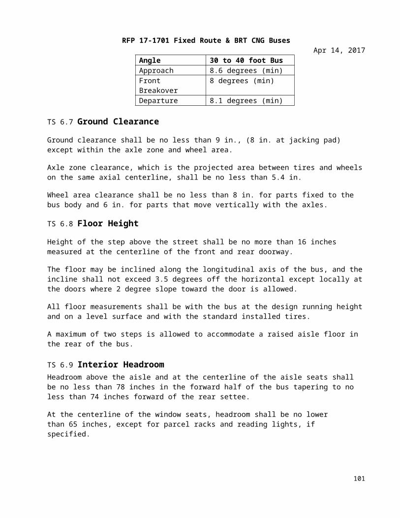
RFP 17-1701 Fixed Route & BRT CNG BusesApr 14, 2017
Major junction panels shall be readily accessible for maintenance, not located behind or alongside seat or other fixed/semi-fixed obstructions. Access panels and junction box covers shall have seals which will preclude entry of rain, wash water, road debris, etc. All wiring and junction panel terminals shall be numbered and color coded for easy identification. A diagram showing the coding as the bus was built shall be furnished.
The Contractor shall supply at least two spare circuits in the main harness between the front and rear of the bus. The main harness from the engine compartment shall be equipped with multiple circuit cannon type connectors.
TS 26.4 Hardware Mounting The mounting of the hardware shall not be used to provide the sole source ground, and all hardware shall be isolated from potential EMI/RFI, as referenced in SAE J1113.
All electrical/electronic hardware mounted in the interior of the vehicle shall be inaccessible to passengers and hidden from view unless intended to be viewed. The hardware shall be mounted in such a manner as to protect it from splash or spray.
All electrical/electronic hardware mounted on the exterior of the vehicle that is not designed to be installed in an exposed environment shall be mounted in a sealed enclosure.
All electrical/electronic hardware and its mounting shall comply with the shock and vibration requirements of SAE J1455.
General Electrical RequirementsTS 26.5 Batteries Low Voltage Batteries (24V)Two (2) Group 31 series Northstar Maintenance Free absorbed glass matt (AGM) batteries shall be provided. Each battery shall have a minimum of 1000 cold cranking amps (CCA) at 0° F. KBi KAPower ultra capacitors shall be used in conjunction with the AGM batteries to provide effective power storage and to ensure successful engine starting. Ultra capacitor technology is to be used for cranking applications and then employing AGM battery technology to manage auxiliary loads. Ultra capacitors shall deliver their storage electrical energy at a high crank rate in a variety of extreme temperatures to provide reliable and consistent starting. The Ultra capacitors shall be rated at a minimum of 120 kJ for cold climates and 75 kJ for warmer climates. The batteries and capacitors shall be designed and installed to withstand the operating environment in Oklahoma. Each battery shall have a purchase date of no more than one year from the date of release for shipment to MTTA.
As an option, four (4) Group 31 Batteries will be made available and priced separately.
TS 26.6 Battery CablesThe battery terminal ends and cables shall be color-coded with red for the primary positive, black for nega-tive, and another color for any intermediate voltage cables. Positive and negative battery cables shall not cross each other if at all possible, be flexible and sufficiently long to reach the batteries with the tray in the extended position without stretching or pulling on any connection and shall not lie directly on top of the batteries. Except as interrupted by the master battery switch, battery and starter wiring shall be continuous
101
RFP 17-1701 Fixed Route & BRT CNG BusesApr 14, 2017
cables with connections secured by bolted terminals and shall conform to specification requirements of SAE Standard J1127 – Type SGT, SGX or GXL and SAE Recommended Practice J541.
TS 26.7 Master Battery SwitchA single master switch shall be provided near the battery compartment for the disconnecting of all battery positives (12V and 24V), except for safety devices such as the fire suppression system and other systems as specified. The location of the master battery switch shall be clearly identified on the exterior access panel, be accessible in less than 10 seconds for deactivation and prevent corrosion from fumes and battery acid when the batteries are washed off or are in normal service. The access door shall be labeled "Battery Emer-gency Shut-Off Switch."
Turning the master switch off with the powerplant operating shall shut off the engine and shall not damage any component of the electrical system. The master switch shall be capable of carrying and interrupting the total circuit load.
TS 26.8 Jump Start ConnectorA jump-start connector, red for 24V and blue for 12V, shall be provided at a location determined at the pre-production meeting and shall be equipped with dust cap and adequately protected from moisture, dirt and debris.
TS 26.9 Battery CompartmentThe battery compartment must be well-ventilated to prevent hydrogen buildup while protecting the com-partment from road spray, water intrusion and de-icing chemicals. Batteries shall be mounted in a stainless steel slide out tray on rollers, with less than 50 lbs. of effort. The battery tray shall have drain holes. The batteries shall not be located in the engine compartment.
The vehicle shall be equipped with a 12VDC and 24VDC quick disconnect switch(es). The battery compart-ment door shall conveniently accommodate operation of the 12VDC and 24VDC quick disconnect switch(es).
TS 26.10 Alternator/RegulatorAn EMP alternator shall supply the entire nighttime operating electrical load of the coach while providing at least 20 percent (20%) of its current output for battery charging when the battery is fully discharged.
The Niehoff 803 alternator will be made available and priced as an option.
TS 26.11 Circuit ProtectionAll branch circuits, except battery-to-starting motor and battery-to-generator/alternator circuits, shall be protected by current-limiting devices such as circuit breakers, fuses, or solid state devices sized to the re-quirements of the circuit. Electronic circuit protection for the cranking motor shall be provided to prevent engaging of the motor for more than 30 seconds at a time to prevent overheating. The circuit breakers or fuses shall be easily accessible for authorized personnel. Fuses shall be used only where it can be demon-strated that circuit breakers are not practicable. This requirement applies to in-line fuses supplied by either the Contractor or a Supplier. Fuse holders shall be constructed to be rugged and waterproof. All manual re-set circuit breakers critical to the operation of the bus shall be mounted in a location convenient to Tulsa Transit mechanic with visible indication of open circuits.
102
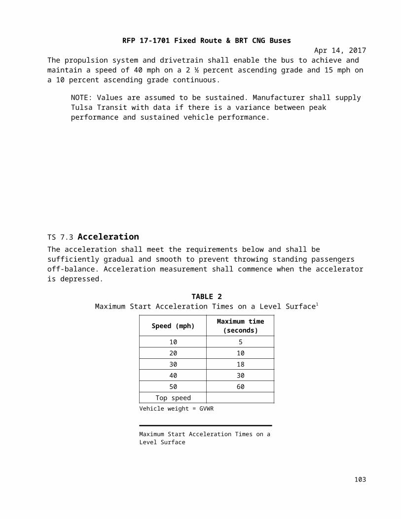
RFP 17-1701 Fixed Route & BRT CNG BusesApr 14, 2017
Tulsa Transit shall consider the application of automatic reset circuit breakers on a case-by-case basis. The Contractor shall show all in-line fuses in the final harness drawings. Any manually resettable circuit breakers shall provide a visible indication of open circuits. Circuit breakers or fuses shall be sized to a minimum of 15 percent larger than the total circuit load. The current rating for the wire used for each circuit must exceed the size of the circuit protection being used.
TS 26.12 Grounds The battery shall be grounded to the vehicle chassis/frame at one location only, as close to the batteries as possible. When using a chassis ground system, the chassis shall be grounded to the frame in multiple locations, evenly distributed throughout the vehicle to eliminate ground loops. No more than four ground ring/spade terminal connections shall be made per ground stud. Electronic equipment requiring an isolated ground to the battery (i.e., electronic ground) shall not be grounded through the chassis.
TS 26.13 Low Voltage/Low Current Wiring and Terminals All power and ground wiring shall conform to specification requirements of SAE Recommended Practice J1127, J1128 and J1292. Double insulation shall be maintained as close to the junction box, electrical compartment or terminals as possible. The requirement for double insulation shall be met by wrapping the harness with plastic electrical tape or by sheathing all wires and harnesses with non-conductive, rigid or flexible conduit.
Wiring shall be grouped, numbered and/or color-coded. Wiring harnesses shall not contain wires of different voltage classes unless all wires within the harness are insulated for the highest voltage present in the harness. Kinking, grounding at multiple points, stretching, and exceeding minimum bend radius shall be prevented.
Strain-relief fittings shall be provided at all points where wiring enters electrical compartments. Grommets or other protective material shall be installed at points where wiring penetrates metal structures outside of electrical enclosures. Wiring supports shall be protective and non-conductive at areas of wire contact and shall not be damaged by heat, water, solvents or chafing.
To the extent practicable, wiring shall not be located in environmentally exposed locations under the vehicle. Wiring and electrical equipment necessarily located under the vehicle shall be insulated from water, heat, corrosion and mechanical damage. Where feasible, front to rear electrical harnesses should be installed above the window line of the vehicle.
All wiring harnesses over 5 ft. long and containing at least five wires shall include 10 percent (minimum one wire) excess wires for spares. This requirement for spare wires does not apply to data links and communication cables. Wiring harness length shall allow end terminals to be replaced twice without pulling, stretching or replacing the wire.
Terminals shall be crimped to the wiring according to the connector manufacturer’s recommendations for techniques and tools. All cable connectors shall be locking type, keyed and sealed, unless enclosed in watertight cabinets or vehicle interior. Pins shall be removable, crimp contact type, of the correct size and rating for the wire being terminated. Unused pin positions shall be sealed with sealing plugs. Adjacent connectors shall either use different inserts or different insert orientations to prevent incorrect connections.
103
RFP 17-1701 Fixed Route & BRT CNG BusesApr 14, 2017
Terminals shall be crimped, corrosion-resistant and full ring type or interlocking lugs with insulating ferrules. When using pressure type screw terminal strips, only stranded wire shall be used. Insulation clearance shall ensure that wires have a minimum of “visible clearance” and a maximum of two times the conductor diameter or 1/16 in., whichever is less. When using shielded or coaxial cable, upon stripping of the insulation, the metallic braid shall be free from frayed strands that can penetrate the insulation of the inner wires.
Ultra-sonic and T-splices may be used with 7 AWG or smaller wire. When a T-splice is used, it shall meet these additional requirements:
• It shall include a mechanical clamp in addition to solder on the splice. • The wire shall support no mechanical load in the area of the splice. • The wire shall be supported to prevent flexing.
All splicing shall be staggered in the harness so that no two splices are positioned in the same location within the harness.
Wiring located in the engine compartment shall be routed away from high-heat sources or shielded and/or insulated from temperatures exceeding the wiring and connector operating requirements.
The instrument panel and wiring shall be easily accessible for service from the Operator’s seat or top of the panel. The instrument panel shall be separately removable and replaceable without damaging the instrument panel or gauges. Wiring shall have sufficient length and be routed to permit service without stretching or chafing the wires.
TS 26.14 Electrical ComponentsAll electrical components, including switches, relays, flashers and circuit breakers, shall be heavy-duty designs with either a successful history of application in heavy-duty vehicles or design specifications for an equivalent environment.
All electric motors shall be heavy-duty brushless type where practical, and have a continuous duty rating of no less than 40,000 hours (except cranking motors, washer pumps and wiper motors). All electric motors shall be easily accessible for servicing.
TS 26.15 Electrical CompartmentsAll relays, controllers, flashers, circuit breakers and other electrical components shall be mounted in easily accessible electrical compartments. All compartments exposed to the outside environment shall be corrosion-resistant and sealed. The components and their functions in each electrical compartment shall be identified and their location permanently recorded on a drawing attached to the inside of the access panel or door. The drawing shall be protected from oil, grease, fuel and abrasion.
The front compartment shall be completely serviceable from the operator’s seat, vestibule or from the outside. “Rear start and run” controls shall be mounted in an accessible location in the engine compartment and shall be protected from the environment.
104
RFP 17-1701 Fixed Route & BRT CNG BusesApr 14, 2017
TS 26.16 General Electronic RequirementIf an electronic component has an internal real-time clock, it shall provide its own battery backup to monitor time when battery power is disconnected, and/or it may be updated by a network component. If an elec-tronic component has an hour meter, it shall record accumulated service time without relying on battery backup.
All electronic component Suppliers shall ensure that their equipment is self-protecting in the event of shorts in the cabling, and also in over-voltage (over 32V DC on a 24V DC nominal voltage rating with a maximum of 50V DC) and reverse polarity conditions. If an electronic component is required to interface with other com-ponents, it shall not require external pull-up and/or pull-down resistors. Where this is not possible, the use of a pull-up or pull-down resistor shall be limited as much as possible and easily accessible and labeled.
TS 26.17 Wiring & TerminalsKinking, grounding at multiple points, stretching, and reducing the bend radius below the manufacturer’s recommended minimum shall not be permitted.
TS 26.18 Discrete Inputs/Outputs (I/O)All wiring to I/O devices, either at the harness level or individual wires, shall be labeled, stamped, or color coded in a fashion that allows unique identification at a spacing not exceeding 4 inches. Wiring for each I/O device shall be bundled together. If the I/O terminals are the same voltages, then jumpers may be used to connect the common nodes of each I/O terminal.
TS 26.19 ShieldingAll wiring that requires shielding shall meet the following minimum requirements. A shield shall be gener-ated by connecting to a ground, which is sourced from a power distribution bus bar or chassis. A shield shall be connected at one location only, typically at one end of the cable. However certain standards or special re-quirements, such as SAE J1939 or RF applications, have separate shielding techniques that also shall be used as applicable.
NOTE: A shield grounded at both end forms a ground loop, which can cause intermittent control or faults.
When using shielded or coaxial cable, upon stripping of the insulation, the metallic braid shall be free from frayed strands, which can penetrate the insulation of the inner wires. To prevent the introduction of noise, the shield shall not be connected to the common side of a logic circuit.
TS 26.20 CommunicationsThe data network cabling shall be selected and installed according to the selected protocol requirements. The physical layer of all network communication systems shall not be used for any purpose other than com-munication between the system components, unless provided for in the network specifications.
Communications networks that use power line carriers (e.g., data modulated on a 24V-power line) shall meet the most stringent applicable wiring and terminal specifications.
TS 26.21 Radio Frequency (RF)RF components, such as radios, video devices, cameras, global positioning systems (GPS), etc., shall use coaxial cable to carry the signal. All RF systems require special design consideration for losses along the ca-
105
RFP 17-1701 Fixed Route & BRT CNG BusesApr 14, 2017
ble. Connectors shall be minimized, since each connector and crimp has a loss that will attribute to attenua-tion of the signal. Cabling should allow for the removal of antennas or attached electronics without remov-ing the installed cable between them. If this cannot be done, then a conduit of sufficient size shall be pro-vided for ease of attachment of antenna and cable assembly. The corresponding component vendors shall be consulted for proper application of equipment, including installation of cables.
TS 26.22 AudioCabling used for microphone level and line level signals shall be 22 AWG minimum with shielded twisted pair. Cabling used for amplifier level signals shall be 18 AWG minimum.
TS 26.23 Multiplexing – GeneralThe Dinex multiplexing system shall control of components necessary to operate the vehicle. This is accom-plished by processing information from input devices and controlling output devices through the use of an internal logic program.
Versatility and future expansion shall be provided for by expandable system architecture. The multiplex sys-tem shall be capable of accepting new inputs and outputs through the addition of new modules and/or the utilization of existing spare inputs and outputs.
All like components in the multiplex system shall be modular and interchangeable with self-diagnostic capa-bilities. The modules shall be easily accessible for troubleshooting electrical failures and performing system maintenance. Multiplex input/output modules shall use solid-state devices to provide extended service life and individual circuit protection.
Ten percent (10%) of the total number of inputs and outputs, or at least one each for each voltage type uti-lized (0V, 12V, 24V) at each module location shall be designated as spares.
TS 26.24 Data Communications – GeneralAll data communication networks shall be either in accordance with a nationally recognized interface stan-dard, such as those published by SAE, IEEE or ISO, or shall be published to Tulsa Transit with the following minimum information:
i. Protocol requirements for all timing issues (bit, byte, packet, inter-packet timing, idle line timing, etc.) packet sizes, error checking, and transport (bulk transfer of data to/from the device).
ii. Data definition requirements that ensure access to diagnostic information and performance characteristics.
iii. The capability and procedures for uploading new application or configuration data.
iv. Access to revision levels of data, application software, and firmware.
v. The capability and procedures for uploading new firmware or application software.
vi. Evidence that applicable data shall be broadcast to the network in an efficient manner such that the overall network integrity is not compromised.
106
RFP 17-1701 Fixed Route & BRT CNG BusesApr 14, 2017
Any electronic vehicle components used on a network shall be conformance tested to the corresponding network standard.
TS 26.25 Drivetrain LevelDrivetrain components, consisting of the engine, transmission, retarder, anti-lock braking system, and all other related components, shall be integrated and communicate fully with respect to vehicle operation with data using SAE Recommended Communications Protocols such as J1939 and/or J1708/J1587 with forward and backward compatibilities or other open protocols.
TS 26.26 Diagnostics, Fault Detection and Data AccessDrivetrain performance, maintenance and diagnostic data, and other electronic messages shall be formatted and transmitted on the communications networks.
The drivetrain level shall have the ability to record abnormal events in memory and provide diagnostic codes and other information to service personnel. At a minimum, this network level shall provide live/fail status, current hardware serial number, software/data revisions, and uninterrupted timing functions.
TS 26.27 Programmability (Software)The drivetrain level components shall be programmable by Tulsa Transit with limitations as specified by the sub-system Supplier.
TS 27. Multiplex LevelTS 27.1 Data AccessAt a minimum, information shall be made available via a communication port on the multiplex system. The location of the communication port shall be easily accessible. A hardware gateway and/or wireless commu-nications system are options if requested by Tulsa Transit.
TS 27.2 Diagnostics & Fault DetectionThe multiplex system shall have a proven method of determining its status (system health and input/output status) and detecting either active (online) or inactive (offline) faults through the use of on-board visual/au-dible indicators.
In addition to the indicators, the system shall employ an advanced diagnostic and fault detection system, which shall be accessible via either a personal computer or a handheld unit. Either unit shall have the ability to check logic function. The diagnostic data can be incorporated into the information level network or the central data access system.
TS 27.3 Programmability (Software)The multiplex system shall have security provisions to protect its software from unwanted changes. This shall be achieved through any or all of the following procedures:
i. password protectionii. limited distribution of the configuration softwareiii. limited access to the programming tools required to change the software
107
RFP 17-1701 Fixed Route & BRT CNG BusesApr 14, 2017
iv. hardware protection that prevents undesired changes to the software
Provisions for programming the multiplex system shall be possible through a PC or laptop. The multiplex sys-tem shall have proper revision control to ensure that the hardware and software are identical on each vehi-cle equipped with the system. Revision control shall be provided by all of the following:
i. hardware component identification where labels are included on all multiplex hardware to identify components
ii. hardware series identification where all multiplex hardware displays the current hardware serial number and firmware revision employed by the module
iii. software revision identification where all copies of the software in service displays the most recent revision number
iv. a method of determining which version of the software is currently in use in the multiplex system
TS 27.4 Electronic Noise ControlElectrical and electronic sub-systems and components on all buses shall not emit electromagnetic radiation that will interfere with on-board systems, components or equipment, telephone service, radio or TV recep-tion, or violate regulations of the Federal Communications Commission.
Electrical and electronic sub-systems on the buses shall not be affected by external sources of RFI/EMI. This includes, but is not limited to, radio and TV transmission, portable electronic devices including computers in the vicinity of or onboard the buses, A/C or D/C power lines, and RFI/EMI emissions from other vehicles.
OPERATOR PROVISIONS, CONTROLS AND INSTRUMENTATIONTS 28. Operator Provisions, Controls and InstrumentationTS 28.1 GeneralIn general when designing the Operator’s area, it is recommended that SAE J833, “Human Physical Dimensions,” be used.
Switches and controls shall be divided into basic groups and assigned to specific areas, in conformance with SAE Recommended Practice J680, Revised 1988, “Location and Operation of Instruments and Controls in Motor Truck Cabs,” and be essentially within the hand reach envelope described in SAE Recommended Practice J287, “Operator Hand Control Reach.”
TS 28.2 Glare The Operator’s work area shall be designed to minimize glare to the extent possible. Objects within and adjacent to this area shall be matte black or dark gray in color wherever possible to reduce the reflection of light onto the windshield. The use of polished metal and light-colored surfaces within and adjacent to the Operator’s area shall be avoided.
TS 28.3 Visors/Sun ShadesFront and Side Sun Shade/VisorAn adjustable roller type sunscreen shall be provided over the operator’s windshield and/or the operator’s side window. The sunscreen shall be capable of being lowered to the midpoint of the operator’s window. When deployed, the screen shall be secure, stable and shall not rattle, sway or intrude into the operator’s
108
RFP 17-1701 Fixed Route & BRT CNG BusesApr 14, 2017
field of view due to the motion of the bus or as a result of air movement. Once lowered, the screen shall re-main in the lowered position until returned to the stowed position by the operator. Sunscreen shall be shaped to minimize light leakage between the visor and windshield pillars to the extent possible.
Visors shall store out of the way and shall not obstruct airflow from the climate control system or interfere with other equipment, such as the radio handset or the destination control. Deployment of the visors shall not restrict vision of the rearview mirrors. Visor adjustments shall be made easily by hand with positive lock-ing and releasing devices and shall not be subject to damage by over-tightening. Sun visor construction and materials shall be strong enough to resist breakage during adjustments.
TS 28.4 Operator’s ControlsFrequently used controls must be in easily accessible locations. These include the door control, kneel control, windshield wiper/washer controls, ramp, and lift and run switch. Any switches and controls necessary for the safe operation of the bus shall be conveniently located and shall provide for ease of operation. They shall be identifiable by shape, touch and permanent markings. Controls also shall be located so that passengers may not easily tamper with control settings.
All panel-mounted switches and controls shall be marked with easily read identifiers. Graphic symbols shall conform to SAE Recommended Practice J2402, “Road Vehicles – Symbols for Controls, Indicators, and Tell Tales,” where available and applicable. Color of switches and controls shall be dark with contrasting typography or symbols.
Mechanical switches and controls shall be replaceable, and the wiring at these controls shall be serviceable from a convenient location. Switches, controls and instruments shall be dust- and water-resistant.
TS 28.5 Normal Bus Operation Instrumentation and ControlsThe following list identifies bus controls used to operate the bus. These controls are either frequently used or critical to the operation of the bus. They shall be located within easy reach of the operator. The operator shall not be required to stand or turn to view or actuate these controls unless specified otherwise.
Systems or components monitored by onboard diagnostics system shall be displayed in clear view of the operator and provide visual and/or audible indicators. The intensity of indicators shall permit easy determination of on/off status in bright sunlight but shall not cause a distraction or visibility problem at night. All indicators shall be illuminated using backlighting.
The indicator panel shall be located in Area 1 or Area 5, within easy view of the operator instrument panel. All indicators shall have a method of momentarily testing their operation. The audible alarm shall be tamper-resistant and shall have an outlet level between 80 and 83 dBA when measured at the location of the operator’s ear.
On-board displays visible to the operator shall be limited to indicating the status of those functions described herein that are necessary for the operation of the bus. All other indicators needed for diagnostics and their related interface hardware shall be concealed and protected from unauthorized access. Table 6 represents instruments and alarms. The intent of the overall physical layout of the indicators shall be in a logical grouping of systems and severity nature of the fault.
109
RFP 17-1701 Fixed Route & BRT CNG BusesApr 14, 2017
Consideration shall be provided for future additions of spare indicators as the capability of onboard diagnostic systems improves. Blank spaces shall contain LEDs.
110
RFP 17-1701 Fixed Route & BRT CNG BusesApr 14, 2017
TABLE 3Transit Bus Instruments & Alarms
Device Description Location Function Visual/ Audible
Master run switch
Rotary, four-position detent Side console
Master control for bus, off, day run, night run and clearance ID lights
Engine start, front
Approved momentary switch Side console Activates engine starter motor
Engine start, rear
Approved momentary switch
Engine com-partment Activates engine starter motor
Engine run, rear Three-position toggle switch
Engine com-partment
Permits running engine from rear start, normal front run position and off
Amber light
Drive selector Touch panel switch Side console Provides selection of propulsion: forward, reverse and neutral Gear selection
HVAC Switch or switches to control HVAC Upper Sawtooth
Permits selection of passenger ventilation: off, cool, heat, low fan, high fan or full auto with on/off only
Operator’s ven-tilation
Rotary, three-position detent
Side console or Dash left wing
Permits supplemental ventilation: fan off, low or high
Defroster fan Rotary, three-position detent
Side console or Dash left wing
Permits defroster: fan off, low, medium or high
Defroster tem-perature Variable position Side console or
Dash left wingAdjusts defroster water flow and temperature
Windshield wiper
One-variable rotary position operating both wipers
Dash left wing Variable speed control of left and right windshield wipers
Windshield washer Push button Dash left wing Activates windshield washers
Dash panel lights
Rotary rheostat or stepping switch
Side Console or Dash left wing
Provides adjustment for light in-tensity in night run position
Interior lights Three-position switch Side consoleSelects mode of passenger com-partment lighting: off, on, nor-mal
Fast idle Two-position switch Side console Selects high idle speed of engine
WC ramp/ kneel enable Two-position switch1 Side console or
Dash right wing
Permits operation of ramp and kneel operations at each door re-mote panel
Amber light
111
RFP 17-1701 Fixed Route & BRT CNG BusesApr 14, 2017
Device Description Location Function Visual/ Audible
Front door ramp/kneel en-able
Two-position keyed
switch1Front door re-mote or Dash right wing
Permits ramp and kneel activa-tion from front door area, key
required1Amber light
Front door ramp Three-position mo-mentary switch
Right side of steering wheel
Permits deploy and stow of front ramp Red light
Front kneel Three-position mo-mentary switch
Right Side of Steering Wheel
Permits kneeling activation and raise and normal at front door re-mote location
Amber or red dash indicator. Ext alarm and Amber light
Rear door ramp/kneel en-able
Two-position keyed
switch1Rear door re-mote
Permits ramp and kneel activa-tion from rear door area, key re-
quired1Red light
Silent alarmRecessed push button, NO and NC contacts momentary
Side console
Activates emergency radio alarm at dispatch and permits covert microphone and/or enables des-tination sign emergency message
Video system event switch
Momentary on/off momentary switch with plastic guard
Side console Triggers event equipment, trig-gers event light on dash Amber light
Left remote mirror
Four-position toggle type Side console Permits two-axis adjustment of
left exterior mirrorRight remote mirror
Four-position toggle type Side console Permits two-axis adjustment of
right exterior mirror
Mirror heater Switch or temperature activated Side console Permits heating of outside mir-
rors when required
Passenger door control
Five-position handle type detent or two momentary push but-tons
Side console, forward
Permits open/close control of front and rear passenger doors Red light
Rear door over-ride
Two-position switch in approved location
Side console, forward
Allows operator to override acti-vation of rear door passenger tape switches
Engine shut-down override
Momentary switch with operation pro-tection
Side console Permits operator to override auto engine shutdown
MobilEye Ignition Controlled Windshield/ A pillar
Alerts operator of potential colli-sions Audible and visual
112
RFP 17-1701 Fixed Route & BRT CNG BusesApr 14, 2017
Device Description Location Function Visual/ Audible
Hazard flashers Two-position switch Side console or Dash right wing Activates emergency flashers Two green lights
Fire suppression Red push button with protective cover
Dash left wing or dash center
Permits operator to override and manually discharge fire suppres-sion system
Red light
Farebox inter-face
Farebox bus operator interface panel Near farebox Facilitates operator interaction
with farebox system LCD display
Destination sign interface
Destination sign in-terface panel
In approved lo-cation
Facilitates operator interaction with destination sign system, manual entry
LCD display
Turn signals
Momentary push but-ton (two required) raised from other switches
Left foot panel Activates left and right turn sig-nals
Two green lights and optional audible indicator
PA manual Detented push button In approved lo-cation
Permits operator to manually ac-tivate public address microphone
Low profile mi-crophone
Low-profile discrete Mounting
Steering col-umn
Permits operator to make an-nouncements with both hands on the wheel and focusing on road conditions
High beam Detented push buttonIn approved lo-cation
Permits operator to toggle be-tween low and high beam Blue light
Parking brake Pneumatic PPV Side console or Dash left wing
Permits operator to apply and re-lease parking brake Red light
Park brake re-lease Pneumatic PPV
Vertical side of the side console or dash center
Permits operator to push and hold to release brakes
Remote engine speed Rotary rheostat Engine com-
partment
Permits technician to raise and lower engine RPM from engine compartment
Master door/ in-terlock
Multi-pole toggle, detented
Out of opera-tor’s reach
Permits operator override to dis-able door and brake/throttle in-terlock
Red light
113
RFP 17-1701 Fixed Route & BRT CNG BusesApr 14, 2017
Device Description Location Function Visual/ Audible
Warning inter-locks deacti-vated
Red indicator light Dash panel cen-ter
Illuminates to warn drive that in-terlocks have been deactivated. Red light
Retarder disable Multi-pole switch de-tented
Within reach of Operator or ap-proved location
Permits operator override to dis-able brake retardation/regenera-tion
Red light
Alarm acknowl-edge
Push button momen-tary
Approved loca-tion
Permits operator to acknowledge alarm condition
Rear door pas-senger sensor disable
Multi-pole toggle, detented
In sign com-partment or Op-erator’s barrier compartment
Permits operator to override rear door passenger sensing system
Indicator / alarm test button
Momentary switch or
programming1Dash center panel
Permits operator to activate test of sentry, indicators and audible alarms
All visuals and au-dibles
Auxiliary power
110-volt power re-ceptacle
Approved loca-tion
Property to specify what function to supply
Speedometer
Speedometer, odome-ter, and diagnostic capability, 5-mile in-crements
Dash center panel
Visual indication of speed and distance traveled, accumulated vehicle mileage, fault condition display
Visual
Air pressure gauge
Primary and sec-ondary, 5 psi incre-ments
Dash center panel
Visual indication of primary and secondary air systems Red light and buzzer
Fire detection Bus operator displayProperty spe-cific or dash center
Indication of fire detection acti-vation by zone/location Buzzer and red light
Door obstruc-tion
Sensing of door ob-struction Dash center Indication of rear door sensitive
edge activation Red light and buzzer
Door ajar Door not properly closed
Property spe-cific or dash center
Indication of rear door not prop-erly closed
Buzzer or alarm and red light
Low system air pressure
Sensing low primary and secondary air tank pressure
Dash center Indication of low air system pressure Buzzer and red light
Methane detec-tion function
Detection of system integrity
Property spe-cific or dash center
Detects system failure No start condition, amber light
114
RFP 17-1701 Fixed Route & BRT CNG BusesApr 14, 2017
Device Description Location Function Visual/ Audible
Methane detec-tion
Indication of 20% LED emergency light (LEL)
Property spe-cific or dash center
Detects levels of methane Flashing red at 20% LEL
Methane detec-tion
Indication of 50% LEL
Property spe-cific or dash center
Detects levels of methane Solid red at 50% LEL
Engine coolant indicator
Low coolant indicator may be supplied as audible alert and vis-ual and/or text mes-sage
Within opera-tor’s sight Detects low coolant condition Amber light
Hot engine in-dicator
Coolant temperature indicator may be sup-plied as audible alert and visual and/or text message
Within opera-tor’s sight
Detects hot engine condition and initiates time delay shutdown Red light
Low engine oil pressure indica-tor
Engine oil pressure indicator may be sup-plied as audible alert and visual and/or text message
Within opera-tor’s sight
Detects low engine oil pressure condition and initiates time- de-layed shutdown
Red light
ABSindicator Detects system status Dash center Displays system failure Amber light
HVACindicator Detects system status Dash center Displays system failure Amber or red light
Charging sys-tem indicator (12/24 V)
Detect charging sys-tem status Dash center
Detects no charge condition and optionally detects battery high, low, imbalance, no charge con-dition, and initiates time-delayed shutdown
Red light flashing or solid based on con-dition
Bike rack de-ployed indica-tor
Detects bike rack po-sition Dash center Indication of bike rack not being
in fully stowed position Amber or red light
Fuel tank levelAnalog gauge, gradu-ated based on fuel type
Dash center Indication of fuel tank level/pressure
1. Indicate area by drawing. Break up switches control from indictor lights.
115
RFP 17-1701 Fixed Route & BRT CNG BusesApr 14, 2017
TS 28.6 Operator Foot ControlsAccelerator and brake pedals shall be designed for ankle motion. Foot surfaces of the pedals shall be faced with wear-resistant, nonskid, replaceable material.
TS 28.7 Pedal AngleThe vertical angle of the accelerator and brake pedals shall be determined from a horizontal plane regard-less of the slope of the cab floor. The accelerator and brake pedals shall be positioned at an angle of 37 to 50 degrees at the point of initiation of contact and extend downward to an angle of 10 to 18 degrees at full throttle.
The location of the brake and accelerator pedals shall be determined by the manufacturer, based on space needs, visibility, lower edge of windshield, and vertical H-point.
TS 28.8 Pedal Dimensions and PositionThe floor-mounted accelerator pedal shall be 10 to 12 inches long and 3 to 4 inches wide. Clearance around the pedal must allow for no interference precluding operation.
As an option, adjustable brake/accelerator pedals will be made available and priced separately.
TS 29. Operator Foot SwitchesTS 29.1 Floor Mounted Foot Control PlatformThe angle of the turn signal platform shall be determined from a horizontal plane, regardless of the slope of the cab floor. The turn signal platform shall be angled at a minimum of 10 degrees and a maximum of 37 de-grees. It shall be located no closer to the seat front than the heel point of the accelerator pedal.
TS 29.2 Turn Control SwitchesTurn signal controls shall be floor-mounted, foot-controlled, water-resistant, heavy-duty, momentary con-tact switches.
TS 29.3 Foot Switch ControlThe control switches for the turn signals shall be mounted on an inclined, floor-mounted stainless steel en-closure or metal plate mounted to an incline integrated into the operator’s platform, located to the left of the steering column. The location and design of this enclosure shall be such that foot room for the operator is not impeded. The inclined mounting surface shall be skid-resistant. All other signals, including high beam and public address system shall be in approved location.
The foot switches shall be UL-listed, heavy-duty type, of a rugged, corrosion-resistant metal construction. The foot switches for the directionals shall be momentary type, while those for the PA system and the high beam shall be latching type. The spacing of the switches shall be such that inadvertent simultaneous deflec-tion of switches is prevented.
116
RFP 17-1701 Fixed Route & BRT CNG BusesApr 14, 2017
TS 29.4 Other Floor Mounted ControlsThe following may be floor mounted, momentary, or latching, as identified by Tulsa Transit at the pre-pro-duction meeting.
(1) hazard(2) silent alarm(3) PA system
TS 30. Operator’s amenitiesTS 30.1 Coat HookA hook and tie-back loop shall be provided to secure the operator’s coat. It shall be mounted above and to the left rear of the operator’s head level behind the operator’s seat.
A dash mounted cup (BIG GULP) holder will made available.
TS 31. Windshield Wipers and WashersTS 31.1 Windshield WipersThe bus shall be equipped with a windshield wiper for each half of the windshield. At 60 mph, no more than 10 percent of the wiped area shall be lost due to windshield wiper lift. For two-piece windshields, both wipers shall park along the center edges of the windshield glass. For single-piece windshields, wipers shall park along the bottom edge of the windshield. Windshield wiper motors and mechanisms shall be easily ac-cessible for repairs or service. The fastener that secures the wiper arm to the drive mechanism shall be cor-rosion-resistant. Electric wipers will be used.
TS 31.2 Intermittent Wiper with Variable ControlA variable-speed feature shall be provided to allow adjustment of wiper speed for each side of the wind-shield between approximately five (5) and twenty-five (25) cycles per minute.
TS 31.3 Non-Synchronized WipersFor non-synchronized wipers, separate controls for each side shall be supplied.
TS 31.4 Windshield WashersThe windshield washer system, when used with the wipers, shall deposit washing fluid evenly and com-pletely wet the entire wiped area.
The windshield washer system shall have a minimum 3-gallon reservoir, located for easy refilling from out-side of the bus. Reservoir pumps, lines, and fittings shall be corrosion-resistant and must include a means to determine fluid level.
TS 32. Operator’s SeatTS 32.1 DimensionsThe Operator’s seat shall be comfortable and adjustable so that people ranging in size from a 95th-percentile male to a 5th-percentile female may operate the bus.
The seat will be a Recaro Ergo Metro AM 80 with a two point seat belt.
117
RFP 17-1701 Fixed Route & BRT CNG BusesApr 14, 2017
An operator’s seat alarm will be made available.
As an option, the Recaro Ergo Metro w/ 3-point seat belt, USSC 9100 ALX, USSC 9100 ALX3, USSC G2 will be made available and priced separately.
As an option, a silicone cushion for the operator’s seat will be made available and priced separately.
118
RFP 17-1701 Fixed Route & BRT CNG BusesApr 14, 2017
Operator’s SeatFigure 4
TS 32.2 Seat Pan Cushion LengthMeasurement shall be from the front edge of the seat pan to the rear at its intersection with the seat back. The adjustment of the seat pan length shall be no less than 16.5 inches at its minimum length and no more than 20.5 inches at its maximum length.
TS 32.3 Seat Pan Cushion Height DimensionsMeasurement shall be from the cab floor to the top of the level seat at its center midpoint. The seat shall adjust in height from a minimum of 14 inches, with a minimum 6 inches vertical range of adjustment.
TS 32.4 Seat Pan Cushion SlopeMeasurement is the slope of the plane created by connecting the two high points of the seat, one at the rear of the seat at its intersection with the seat back and the other at the front of the seat just before it wa-terfalls downward at the edge. The slope can be measured using an inclinometer and shall be stated in de-grees of incline relative to the horizontal plane (0 degrees). The seat pan shall adjust in its slope from no less than plus 12 degrees (rearward “bucket seat” incline), to no less than minus 5 degrees (forward slope).
TS 32.5 Seat Base Fore/Aft AdjustmentMeasurement is the horizontal distance from the heel point to the front edge of the seat. The minimum and maximum distances shall be measured from the front edge of the seat when it is adjusted to its minimum seat pan depth (approximately 15 inches). On all low-floor buses, the seat-base shall travel horizontally a minimum of 9 inches. It shall adjust no closer to the heel point than 6 inches.
119
Head Rest
Seat Back
Arm Rest
Seat Belt
Seat Base
Seat Back Lumbar Sup-port
Seat Pan Cushion
RFP 17-1701 Fixed Route & BRT CNG BusesApr 14, 2017
TS 32.6 Seat Pan Cushion WidthMeasurement is the horizontal distance across the seat cushion. The seat pan cushion shall be 17 to 21 inches across at the front edge of the seat cushion and 20 to 23 inches across at the side bolsters.
TS 32.7 Seat Suspension(1) The operator’s seat shall be appropriately dampened to support a minimum weight of 380
lbs. The suspension shall be capable of dampening adjustment in both directions.
(2) Rubber snubbers shall be provided to prevent metal-to-metal contact.
TS 32.8 Seat Back WidthMeasurement is the distance between the outermost points of the front of the seat back, at or near its mid-point in height. The seat back width shall be no less than 19 inches. Seat back will include dual recliner gears on both sides of the seat.
TS 32.9 Seat Back Lumbar SupportMeasurement is from the bottom of the seat back at its intersection with the seat pan to the top of the lum-bar cushioning. The seat back shall provide adjustable depth lumbar back support with three individual op-erating lumbar cells within a minimum range of 7 to 11 inches.
TS 32.10 Seat Back Angle Adjustment(1) The seat back angle shall be measured relative to a level seat pan, where 90 degrees is the
upright position and 90 degrees-plus represents the amount of recline.
(2) The seat back shall adjust in angle from a minimum of no more than 90 degrees (upright) to at least 105 degrees (reclined), with infinite adjustment in between.
TS 32.11 Seat Belt The belt assembly should be an auto-locking retractor (ALR) lap seat belt only.. All seat belts should be stored in automatic retractors. The belts shall be mounted to the seat frame so that the operator may adjust the seat without resetting the seat belt.
The seat and seat belt assemblies as installed in the bus shall withstand static horizontal forces as required in FMVSS 207 and 210. Seatbelt webbing shall be black in color.
TS 32.12 Seat Control LocationsWhile seated, the operator shall be able to make seat adjustments by hand without complexity, excessive effort or being pinched. Adjustment mechanisms shall hold the adjustments and shall not be subject to inad-vertent changes.
TS 32.13 Seat Structure and Materials(1) Cushions
Cushions shall be fully padded with at least 3 in. of materials in the seating areas at the bottom and back.
120
RFP 17-1701 Fixed Route & BRT CNG BusesApr 14, 2017
(2) Cushion MaterialsAll materials used on the seat assembly, passenger and operator’s seat shall meet the flammability requirements of the FMVSS #302. Proof of Compliance must be submitted with proposals.
TS 32.14 PedestalExposed portions of frame and hardware shall be stainless steel or chrome plated.
TS 33. Mirrors TS 33.1 Exterior Mirrors Exterior mirrors shall be Safe Fleet (Hadley) 8” x 18” Class A 2-piece flat and convex. Mirrors shall be remote controlled motorized with black powder coated stainless steel arms that return to original position when moved. Left mirror shall be mounted near the front or upper edge of the operator’s window. Right mirror shall be viewed through the upper right corner of windshield and mounted so as to provide maximum practical clearance to the ground. Mirrors must fold out of way of automatic washer. Metal mirror parts to be chrome plated or stainless steel. Exterior mirrors must utilize a “quick disconnect” for electrical wiring.
As an option, the B&R 10” x 11” 2-piece flat and convex, heated, and remote w/ stainless steel and cast aluminum arms will be made available and priced separately.
TS 33.2 Interior MirrorsMirrors shall be provided for the operator to observe passengers throughout the bus without leaving the seat and without shoulder movement. The operator shall be able to observe passengers in the front/en-trance and rear/exit areas, anywhere in the aisle, and in the rear seats.
A (min) 8½” x 16” rear view mirror shall be provided on the front sign header.
A 6" diameter adjustable convex mirror over and forward of the front door shall be provided. An adjustable convex mirror shall be provided over/above and to the rear of the rear exit door. (Convex mirrors described above are to be used in conjunction with each other.) The glass in this mirror shall be replaceable.
WINDOWSTS 34. General TS 34.1 WindshieldThe windshield shall permit an operator’s field of view as referenced in SAE Recommended Practice J1050. The vertically upward view shall be a minimum of 14 degrees, measured above the horizontal and excluding any shaded band. The vertically downward view shall permit detection of an object 3½ ft. high no more than 2 ft. in front of the bus. The horizontal view shall be a minimum of 90 degrees above the line of sight. Any binocular obscuration due to a center divider may be ignored when determining the 90-degree requirement, provided that the divider does not exceed a 3-degree angle in the operator’s field of view. Windshield pillars shall not exceed 10 degrees of binocular obscuration. The windshield shall be designed and installed to mini-mize external glare as well as reflections from inside the bus.
The windshield shall be easily replaceable by removing zip-locks from the windshield retaining moldings. Bonded-in-place windshields shall not be used. Winglets may be bonded.
121
RFP 17-1701 Fixed Route & BRT CNG BusesApr 14, 2017
As an option, a one piece windshield which incorporates the destination sign shall be made available and priced separately.
TS 34.2 GlazingThe windshield glazing material shall have a 1/4 inch nominal thickness laminated safety glass conforming to the requirements of ANSI Z26.1 Test Grouping 1A and the Recommended Practices defined in SAE J673.
TS 34.3 Operator’s Side windowThe operator’s side window shall be the sliding type, requiring only the rear half of sash to latch upon clos-ing, and shall open sufficiently to permit the seated operator to easily adjust the street-side outside rearview mirror. When in an open position, the window shall not rattle or close during braking. This window section shall slide in tracks or channels designed to last the service life of the bus. The operator’s side win-dow shall not be bonded in place and shall be easily replaceable. The glazing material shall have a single-density tint.
The operator’s view, perpendicular through operator’s side window glazing, should extend a minimum of 33 inches (840 mm) to the rear of the heel point on the accelerator, and in any case must accommodate a 95th percentile male operator. The view through the glazing at the front of the assembly should begin not more than 26 inches (560 mm) above the operator’s floor to ensure visibility of an under-mounted convex mirror.
Operator’s window construction shall maximize ability for full opening of the window.
The operator’s side window glazing material shall have a 1/4 inch nominal thickness laminated safety glass conforming with the requirements of ANSI Z26.1-1996 Test Grouping 2 and the Recommended Practices de-fined in SAE J673.
The design shall prevent sections from freezing closed in the winter. Light transmittance shall be 75 percent on the glass area below 53 inches from the operator platform floor. On the top fixed over bottom slider con-figuration, the top fixed area above 53 inches may have a maximum 5 percent light transmittance.
TS 34.4 Passenger Side WindowsThe side windows shall be upper transom with lower fixed. With the exception of the upper portion of first right-hand and /or left hand window where the side destination sign shall be located, all other shall be tinted 7/32" 28% gray tinted safety glass and frame windows will have black (dark) polyester powder coat aluminum frames inside and out. Windows shall be flat panel, transit application with approved laminated safety glass (ANSI 25.1). Glazing in the sash shall be easily replaced without removing the sash from the bus. All windows shall be of glass shall be mounted in removable rubber retaining strips/seals.
As an option, Fixed Frame, Framed Transom, Frameless Bonded Fixed, Frameless bonded transom mounted windows will be made available and be priced separately.
A positive lock type emergency latch meeting the FMVSS-217 shall be furnished on each window frame. Each window shall have a permanent decal describing emergency window operation procedures.
122
RFP 17-1701 Fixed Route & BRT CNG BusesApr 14, 2017
Side windows shall be designed to prevent the entrance of air and water when windows are closed. The win-dow seal rubber must be installed so that passengers cannot remove it and rubber shall be of such quality to resist adhering to other sash sill.
TS 35. HEATING, VENTILATING AND AIR CONDITIONINGTS 35.1 Capacity and Performance The Heating, Ventilation, and Air Conditioning (HVAC) climate control system shall be rear-mounted Thermo King T-14(616) Screw Compressor, Brushless Evaporator & Condenser Motors with R134a Freon capable of maintaining the interior of the bus at the temperature and humidity levels defined in the following paragraphs. Accessibility and serviceability of components preferably shall be provided without requiring maintenance personnel to climb up on the roof of the bus.
The following climatic factors shall be used as design guidelines and shall be considered as operational requirements.
Temperature and Solar Load
Ambient air temperature, external equipment:
Minimum ...................................................................... -20ºF
Maximum.....................................................................120ºF
Humidity:
Minimum ........................................................................... 5%
Maximum....................................................................... 100%
Precipitation
Maximum rainfall rate ............................................. 6 inches per hour
Maximum snowfall rate ........................................... 5 inches per hour
Maximum snow accumulation............................................. 18 inches
With the bus running at the design operating profile with corresponding door opening cycle, and carrying a number of passengers equal to 150 percent of the seated load, the HVAC system shall maintain an average passenger compartment temperature within a range between 65° and 80°F, while controlling the relative humidity to a value of 50 percent or less. The system shall maintain these conditions while subjected to any outside ambient temperatures within a range of 10° to 95°F and at any ambient relative humidity levels between 5 and 50 percent. Reheat system water control valve to be pulsing type to provide even heat distribution.
When the bus is operated in outside ambient temperatures of 95° to 115°F, the interior temperature of the bus shall be permitted to rise one degree for each degree of exterior temperature in excess of 95°F. When
123
RFP 17-1701 Fixed Route & BRT CNG BusesApr 14, 2017
bus is operated in outside ambient temperatures in the range of -10°F to +10ºF, the interior temperature of the bus shall not fall below 55°F while bus is running on the Design Operating Profile.
System capacity testing, including pull down/warm-up, stabilization, and profile shall be conducted in accordance to industry standard. Temperature measurements shall be made in accordance:
I. The temperatures measured from a height of 6 inches below the ceiling shall be within plus or minus 3ºF of the average temperature at the top surface of the seat cushions.
II. Temperatures measured more than 3 inches above the floor shall be within plus or minus 5ºF of the average temperature at the top surface of the seat cushions. The interior temperatures, from front to rear of the bus, shall not vary more than plus or minus 3ºF from the average.
III. The recommended locations of temperature probes are only guidelines and may require slight modifications to address actual bus design. Care must be taken to avoid placement of sensing devices in immediate path of air duct outlet. In general, the locations are intended to accurately represent the interior passenger area.
The air conditioning portion of the HVAC system shall be capable of reducing the passenger compartment temperature from 110° to 90°F in less than 20 minutes after engine start-up. Engine temperature shall be within the normal operating range at the time of start-up of the cool-down test and the engine speed shall be limited to fast idle that may be activated by an operator-controlled device. During the cool-down period the refrigerant pressure shall not exceed safe high-side pressures and the condenser discharge air temperature, measured 6 inches from the surface of the coil, shall be less than 45°F above the condenser inlet air temperature. The appropriate solar load representing 4 P.M. on August 21, shall be used. There shall be no passengers on board, and the doors and windows shall be closed. The air conditioning system shall meet these performance requirements using HFC R134a. The climate control blower motors and fan shall be designed such that their operation complies with the interior noise level requirements. There shall be manual shut off valves to isolate the drier, receiver, and compressor.
Note: Air conditioning requirements for hybrid drive batteries, if necessary, shall not activate or degrade the efficiency of the passenger HVAC system.
TS 35.2 Controls and Temperature UniformityThe HVAC system excluding the Operator’s heater/defroster shall be centrally controlled with an advanced electronic/diagnostic control system with provisions for extracting/reading data. The system shall be compliant with J1939 Communication Protocol for receiving and broadcasting of data.
Hot engine coolant water shall be delivered to the HVAC system operator’s defroster/heater and other heater cores by means of an auxiliary coolant pump, sized for the required flow, which is brushless and sealless having a minimum maintenance free service life for both the brushless motor and the pump of at least 40,000 hours at full power.
TS 35.3 Manual Mode Selection of Climate Control SystemAfter manual selection and/or activation of climate control system operation mode, all interior climate con-trol system requirements for the selected mode shall be attained automatically to within plus or minus 2°F of specified temperature control set-point.
124
RFP 17-1701 Fixed Route & BRT CNG BusesApr 14, 2017
TS 35.4 Manually Adjustable Temperature Control Set PointThe climate control system shall have the provision to allow the operator to adjust the temperature control set-point at a minimum of between 68º and 72°F. From then on, all interior climate control system require-ments shall be attained automatically, unless re-adjusted by operator.
The operator shall have full control over the defroster and operator’s heater. The operator shall be able to adjust the temperature in the operator’s area through air distribution and fans. The interior climate control system shall switch automatically to the ventilating mode if the refrigerant compressor or condenser fan fails.
Interior temperature distribution shall be uniform to the extent practicable to prevent hot and/or cold spots. After stabilization with doors closed, the temperatures between any two points in the passenger compart-ment in the same vertical plane, and 6 to 72 inches above the floor, shall not vary by more than 5°F with doors closed. The interior temperatures, measured at the same height above the floor, shall not vary more than plus or minus 5°F from the front to the rear from the average temperature Variations of greater than plus or minus 5°F will be allowed for limited, localized areas provided the majority of the measured temper-atures fall within the specified requirement.
TS 36. Air Flow TS 36.1 Passenger AreaThe cooling mode of the interior climate control system shall introduce air into the bus at or near the ceiling height at a minimum rate of 25 cubic ft. per minute (cfm) per passenger based on the standard configuration bus carrying a number of passengers equal to 150 percent of the seated load. Airflow shall be evenly distributed throughout the bus, with air velocity not exceeding 100 ft. per minute on any passenger. The ventilating mode shall provide air at a minimum flow rate of 20 cfm per passenger.
Airflow may be reduced to 15 cfm per passenger (150 percent of seated load) when operating in the heating mode. The fans shall not activate until the heating element has warmed sufficiently to ensure at least 70 °F air outlet temperature. The heating air outlet temperature shall not exceed 120 °F under any normal operating conditions.
The climate control blower motors and fan shall be designed such that their operation complies with the interior noise level requirements.
TS 36.2 Operator’s AreaThe bus interior climate control system shall deliver at least 100 cfm of air to the Operator’s area when operating in the ventilating and cooling modes. Adjustable nozzles shall permit variable distribution or shutdown of the airflow. Airflow in the heating mode shall be reduced proportionally to the reduction of airflow into the passenger area. The windshield defroster unit shall meet the requirements of SAE Recommended Practice J382, “Windshield Defrosting Systems Performance Requirements,” and shall have the capability of diverting heated air to the Operator’s feet and legs. The defroster or interior climate control system shall maintain visibility through the Operator’s side window.
TS 36.3 Controls for the Climate Control System (CCS)The controls for the Operator’s compartment for heating, ventilation and cooling systems shall be integrated and shall meet the following requirements:
125
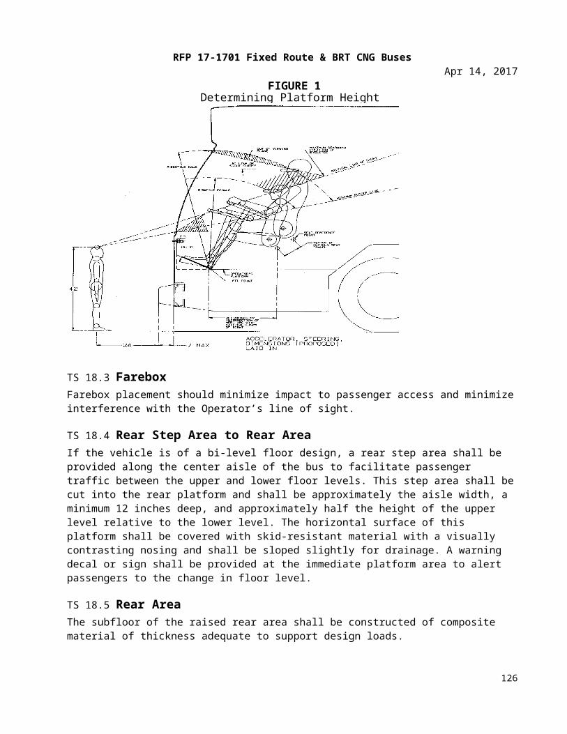
RFP 17-1701 Fixed Route & BRT CNG BusesApr 14, 2017
The heat/defrost system fan shall be controlled by a separate switch that has an “off” position and at least two positions for speed control. All switches and controls shall preclude the possibility of clothing becoming entangled, and shields shall be provided, if required. If the fans are approved by Tulsa Transit, an “on-off” switch shall be located to the right of or near the main defroster switch.
• A manually operated control valve shall control the coolant flow through the heater core.
• If a cable-operated manual control valve is used, the cable length shall be kept to a minimum to reduce cable seizing. Heater water control valves shall be “positive” type, closed or open. The method of operating remote valves shall require the concurrence of Tulsa Transit’s project manager.
TS 36.4 Operator’s Compartment RequirementsA separate heating, ventilation and defroster system for the Operator’s area shall be provided and shall be controlled by the operator. The system shall meet the following requirements:
• The heater and defroster system shall provide heating for the operator and heated air to completely defrost and defog the windshield, Operator’s side window, and the front door glasses in all operating conditions. Fan(s) shall be able to draw air from the bus body interior and/or the exterior through a control device and pass it through the heater core to the defroster system and over the Operator’s feet. A minimum capacity of 100 cfm shall be provided. The operator shall have complete control of the heat and fresh airflow for the Operator’s area.
• The defroster supply outlets shall be located at the lower edge of the windshield. These outlets shall be durable and shall be free of sharp edges that can catch clothes during normal daily cleaning. The system shall be such that foreign objects such as coins or tickets cannot fall into the defroster air outlets. Adjustable ball vents or louvers shall be provided at the left of the Operator’s position to allow direction of air onto the side windows.
The bus interior climate control system shall deliver at least 100 cubic feet per minute of air to the operator’s area when operating in the ventilation, heating, and cooling modes without use of the operator’s booster fan. The climate control system blower motors will operate at the set speed during all operating modes. All return air ducts will be protected by guards constructed of a sturdy mesh which will resist damage.
Adjustable nozzles shall permit variable distribution or shut down of all air flow. The defroster and/or interior climate control system shall maintain visibility through the operator’s side window. A booster fan with operator control shall be provided in the ductwork at the operator’s area, forward of the operator’s position, for increased air flow to the operator. The windshield defroster unit shall meet or exceed all requirements of SAE Recommended Practice J382, Windshield Defrosting Systems Performance Requirements, and shall have the capability of diverting heated air to the operator’s feet and legs.
As an option an auxiliary defrost fan will be made available and priced separately.
TS 36.5 Air FiltrationAir shall be filtered before discharge into the passenger compartment. The filter shall meet the ANSI/ASHRAE 52.1 requirement for 5 percent or better atmospheric dust spot efficiently, 50 percent weight
126
RFP 17-1701 Fixed Route & BRT CNG BusesApr 14, 2017
arrestance, and a minimum dust holding capacity of 120 g per 1000 cfm cell. Air filters shall be easily removable for service.
TS 36.6 FiltersHogs Hair filters shall be provided.
TS 36.7 Roof VentilatorsOne roof ventilator shall be provided in the roof of the bus, approximately over or just forward of the front axle of the bus.
The ventilator shall be easily opened and closed manually. When open with the bus in motion, this ventilator shall provide fresh air inside the bus. The ventilator shall cover an opening area no less than 425 sq. inches and shall be capable of being positioned as a scoop with either the leading or trailing edge open no less than 4 inches, or with all four edges raised simultaneously to a height of no less than 3½ inches. An escape hatch shall be incorporated into the roof ventilator. Roof ventilator shall be sealed to prevent entry of water when closed.TS 37. EXTERIOR PANELS, FINISHES and Exterior LightingTS 37.1 Design The bus shall have a clean, smooth, simple design, primarily derived from bus performance requirements and passenger service criteria. The exterior and body features, including grilles and louvers, shall be shaped to facilitate cleaning by automatic bus washers without snagging washer brushes. Water and dirt shall not be retained in or on any body feature to freeze or bleed out onto the bus after leaving the washer. The body and windows shall be sealed to prevent leaking of air, dust or water under normal operating conditions and during cleaning in automatic bus washers for the service life of the bus.
Exterior panels shall be sufficiently stiff to minimize vibration, drumming or flexing while the bus is in service. When panels are lapped, the upper and forward panels shall act as a watershed. However, if entry of moisture into the interior of the vehicle is prevented by other means, then rear cap panels may be lapped otherwise. The windows, hatches and doors shall be able to be sealed. Accumulation of spray and splash generated by the bus’s wheels shall be minimized on windows and mirrors.
As an option, alternative exterior styling designs will be made available and priced separately.
TS 37.2 MaterialsBody materials shall be selected and the body fabricated to reduce maintenance, extend durability and provide consistency of appearance throughout the service life of the bus. Detailing shall be kept simple, and add-on devices and trim shall be minimized and integrated into the basic design.
TS 37.3 Roof-Mounted EquipmentA non-skid, walkway shall be incorporated on the roof to provide access to equipment without damaging any system or climbing over any equipment.
TS 37.4 Pedestrian SafetyExterior protrusions along the side and front of the bus greater than ½ in. and within 80 in. of the ground shall have a radius no less than the amount of the protrusion. The exterior rearview mirrors, cameras and
127
RFP 17-1701 Fixed Route & BRT CNG BusesApr 14, 2017
required lights and reflectors are exempt from the protrusion requirement. Advertising frames shall protrude no more than ⅞ in. from the body surface. Grilles, doors, bumpers and other features on the sides and rear of the bus shall be designed to minimize toeholds or handholds.
Exterior protrusions shall not cause a line-of-sight blockage for the operator
TS 37.5 Easily Replaceable Lower Side Body PanelsThe lower section of the side body panels (low-floor buses) shall be made of aluminum can be quickly mate-rial and shall be easily and quickly replaceable.
TS 37.6 Rain GuttersRain gutters shall be provided to prevent water flowing from the roof onto the passenger doors and opera-tor’s side window. When the bus is decelerated, the gutters shall not drain onto the windshield, operator’s side window or door boarding area. Cross-sections of the gutters shall be adequate for proper operation.
TS 37.7 License Plate ProvisionsProvisions shall be made to mount standard-size U.S. license plates per SAE J686 on the rear of the bus. These provisions shall direct-mount or recess the license plates so that they can be cleaned by automatic bus-washing equipment without being caught by the brushes. The rear license plate provision shall be illumi-nated per SAE J587.
TS 37.8 Fender SkirtsFeatures to minimize water spray from the bus in wet conditions shall be included in wheel housing design. Any fender skirts shall be easily replaceable. They shall be flexible if they extend beyond the allowable body width. Wheels and tires shall be removable with the fender skirts in place.
TS 37.9 Standard Splash ApronsSplash aprons, composed of 1/4 inch minimum composition or rubberized fabric, shall be installed behind and/or in front of wheels as needed to reduce road splash and protect under floor components. The splash aprons shall extend downward to within 6 inches off the road surface at static conditions. Apron widths shall be no less than tire widths. Splash aprons shall be bolted to the bus understructure. Splash aprons and their attachments shall be inherently weaker than the structure to which they are attached. The flexible portions of the splash aprons shall not be included in the road clearance measurements. Splash apron shall be in-stalled as necessary to protect the wheelchair loading device from road splash. Other splash aprons shall be installed where necessary to protect bus equipment. An approved method of grounding static electricity shall be provided on each bus such as a conductive nylon grounding strap.
TS 38. Service Compartments and Access DoorsTS 38.1 Access Doors
(1) Conventional or pantograph hinged doors shall be used for the engine compartment and for all auxiliary equipment compartments including doors for checking the quantity and adding to the engine coolant, engine lubricant, and transmission fluid. Access openings shall be sized for easy performance of tasks within the compartment, including tool operating space.
128
RFP 17-1701 Fixed Route & BRT CNG BusesApr 14, 2017
(2) Access doors shall be of rugged construction and shall maintain mechanical integrity and function under normal operations throughout the service life of the bus. They shall close flush with the body surface. All doors shall be hinged at the top or on the forward edge and shall be prevented from coming loose or opening during transit service or in bus washing operations. All access doors shall be retained in the open position by props or counterbal-ancing with over-center or gas-filled springs with safety props and shall be easily operable by one person. Springs and hinges shall be corrosion resistant. Latch handles shall be flush with, or recessed behind, the body contour and shall be sized to provide an adequate grip for opening. Access doors, when opened, shall not restrict access for servicing other compo-nents or systems.
(3) If precluded by design, the manufacturer shall provide door design information specifying how the requirements are met.
TS 38.2 Access Door Latch/Locks(1) The engine compartment, including the exhaust duct plenum, shall be completely sealed to
prevent smoke or fumes from entering the bus interior. The engine bulkhead and exhaust duct plenum shall be insulated adequately to prevent discomfort to passengers due to heat, to minimize hazard in case of fire in the engine compartment, and to aid in controlling noise to meet required levels.
(2) An engine air intake designed to minimize noise shall be provided. Insulation shall be pro-vided as needed in the engine compartment area for sound suppression.
(3) An adequate number of fire detectors shall be furnished in the engine compartment, as de-termined by the bus manufacturer. The detectors shall activate an alarm (visual as well as audible) at the operator’s station.
(4) Access panels to the left and right side of the engine compartment shall be provided with expanded metal inserts to provide heat dissipation in the engine compartment. Panels shall also be constructed so that maintenance personnel can easily reach all under the floor and engine compartment equipment requiring access from outside the bus body. Access panels will be hinged to swing up and out of the way, and be secured with a 5/16 inch square latch.
(5) Gas operated shocks with safety locks shall secure access doors in the open position during inspection and servicing. The engine compartment doors will be equipped with handles. Louvers shall be provided in the rear engine compartment door to optimize airflow. Access doors are not required in the engine door.
(6) Forward edge hinges with positive action hold open springs shall be provided on the fuel connector and lay flat against the adjacent panel when fully opened. The battery access door shall have top edge hinges with gas operated shocks with safety devises when the bat-tery is being serviced. A small access door shall be provided to the battery disconnect switch. Battery disconnect switch, fuel and air tank drain valve doors will be equipped with a well type securing latch.
129
RFP 17-1701 Fixed Route & BRT CNG BusesApr 14, 2017
TS 39. BumpersTS 39.1 LocationBumpers shall provide impact protection for the front and rear of the bus with the top of the bumper being 27 in., ± 2 in., above the ground. Bumper height shall be such that when one bus is parked behind another, a portion of the bumper faces will contact each other.
TS 39.2 Front BumperNo part of the bus, including the bumper, shall be damaged as a result of a 5 mph impact of the bus at curb weight with a fixed, flat barrier perpendicular to the bus’s longitudinal centerline. The bumper shall return to its pre-impact shape within 10 minutes of the impact. The bumper shall protect the bus from damage as a re-sult of 6.5 mph impacts at any point by the common carriage with contoured impact surface defined in Figure 2 of FMVSS 301 loaded to 4000 lbs. parallel to the longitudinal centerline of the bus. It shall protect the bus from damage as a result of 5.5 mph impacts into the corners at a 30-degree angle to the longitudinal centerline of the bus.
The energy absorption system of the bumper shall be independent of every power system of the bus and shall not require service or maintenance in normal operation during the service life of the bus. The bumper may in-crease the overall bus length specified by no more than 7 inches. Mounting provisions will be made for inte-grating bike rack if necessary.
A 2-position Velo Porter composite bike rack will be made available.
As an option an Apex 3 position bike rack will be made available and priced separately.
As an option a dash mounted bike deployed indicator lamp will be made available and priced separately.
As an option a Sportworks 2 position bike rack will be made available and priced separately.
TS 39.3 Rear BumperNo part of the bus, including the bumper, shall be damaged as a result of a 2 mph impact with a fixed, flat barrier perpendicular to the longitudinal centerline of the bus. The bumper shall return to its pre-impact shape within 10 minutes of the impact. When using a yard tug with a smooth, flat plate bumper 2 ft. wide contacting the horizontal centerline of the rear bumper, the bumper shall provide protection at speeds up to 5 mph, over pavement discontinuities up to 1 inch high, and at accelerations up to 2 mph/sec. The rear bumper shall protect the bus, when impacted anywhere along its width by the common carriage with contoured impact surface defined in Figure 2 of FMVSS 301 loaded to 4000 lbs., at 4 mph parallel to or up to a 30-degree angle to, the longitudinal centerline of the bus.
The rear bumper shall be shaped to preclude unauthorized riders standing on the bumper. The bumper shall not require service or maintenance or in normal operation during the service life of the bus. The bumper may increase the overall bus length specified by no more than 7 inches.
130
RFP 17-1701 Fixed Route & BRT CNG BusesApr 14, 2017
TS 39.4 Bumper MaterialBumper material shall be corrosion-resistant and withstand repeated impacts of the specified loads without sustaining damage. Visible surfaces shall be black. These bumper qualities shall be sustained throughout the service life of the bus.
TS 40. Finish and ColorTS 40.1 AppearanceAll exterior surfaces shall be smooth and free of wrinkles and dents. Exterior surfaces to be painted shall be properly prepared as required by the paint system Supplier prior to application of paint to assure a proper bond between the basic surface and successive coats of original paint for the service life of the bus. Drilled holes and cutouts in exterior surfaces shall be made prior to cleaning, priming and painting, where possible, to prevent corrosion. The bus shall be completely painted prior to installation of exterior lights, windows, mirrors and other items that are applied to the exterior of the bus. Body filler materials may be used for surface dressing, but not for repair of damaged or improperly fitted panels.
Paint shall be applied smoothly and evenly with the finished surface free of visible dirt and the following other imperfections:
• blisters or bubbles appearing in the topcoat film• chips, scratches, or gouges of the surface finish• cracks in the paint film• craters where paint failed to cover due to surface contamination• overspray• peeling• runs or sags from excessive flow and failure to adhere uniformly to the surface• chemical stains and water spots• dry patch due to incorrect mixing of paint activators• buffing swirls
All exterior finished surfaces shall be impervious to diesel fuel, gasoline and commercial cleaning agents. Finished surfaces shall resist damage by controlled applications of commonly used graffiti-removing chemicals.
Proper adhesion between the basic surface and successive coats of the original paint shall be measured using an Elcometer adhesion tester as outlined in ASTM D4541-85. Adhesion shall be a minimum 300 ft.-lbs. The bus manufacturer shall supply test samples of the exterior surface for each step of the painting process that may be subject to adhesion testing per ASTM G4541-87 and ASTM D4145-85. ASTM D4541-93 may be used for inspection testing during assembly of the vehicle.
Bus exteriors shall be painted and numbered to include numbers on the roof to the general design to be provided with each order. Minor variations to this color scheme may be required in order to accommodate the specific styling of the Contractor's buses.
Within 30 days of execution of contract, the Contractor shall supply to Procuring Agency the detailed drawings of the front, rear, both sides, and roof of the bus that will be supplied. Within 60 days of execution of the contract, Tulsa Transit will return these drawings to the Contractor with details of the color schemes included.
131
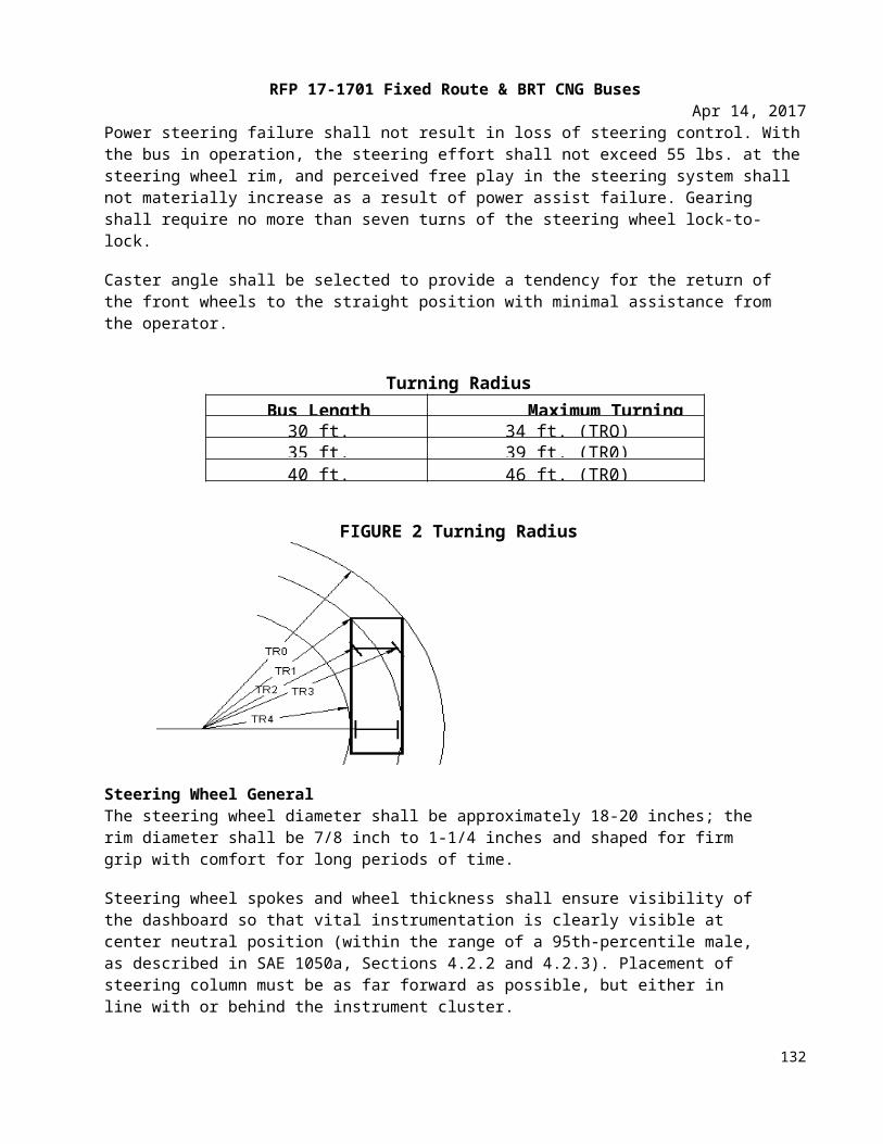
RFP 17-1701 Fixed Route & BRT CNG BusesApr 14, 2017
The bus exterior shall be primed as recommended by the manufacturer of the final finish, and shall be finished with the color scheme specified in the order. Proposers should provide listings of available colors.
There shall be no bare or exposed metal surfaces showing on the exterior of the bus, exclusive of ornamentation and accessories. The display of manufacturer's name or insignia on the exterior of the bus will be as specified in the individual order.
TS 40.2 Decals, Numbering and Signing Monograms, numbers and other special signing shall be applied to the inside and outside of the bus as required. Signs shall be durable and fade-, chip- and peel-resistant. They may be painted signs, decals or pressure-sensitive appliqués. All decals shall be installed per the decal Supplier recommendations. Signs shall be provided in compliance with the ADA requirements defined in 49 CFR Part, Subpart B, 38.27.
Buses shall have fleet numbers applied both on the interior and exterior of the bus in sequence with factory serial numbers. Each individual order will include the correct starting number and the location, size, and color of numbers.
TS 40.3 Passenger InformationADA priority seating signs as required and defined by 49 CFR, Part 38.27 shall be provided to identify the seats designated for passengers with disabilities.
Requirements for a public information system in accordance with 49 CFR, Part 38.35 shall be provided.
Interior decals such as but not limited to the following, “No Smoking”, “Exit” door, “Emergency Exit”, “Watch Your Step”, Wheelchair instructions and "Reserved for Wheelchairs," etc. shall be provided. All decals shall be in English and Spanish. Optional Tri-Lingual decals will be made available, with the three languages being verified at the pre-production meeting. Decals containing identification of windows, hatches, etc., shall also be provided. All decals shall conform to Oklahoma state law.
TS 41. Exterior Lighting Exterior lighting and reflectors shall comply, as applicable, with Part 393, Subpart B of the FMCSA and FMVSS 108.
All exterior lights shall be designed to prevent entry and accumulation of moisture or dust. Commercially available LED-type lamps shall be utilized at all exterior lamp locations. Lamps, lenses and fixtures shall be interchangeable to the extent practicable. Two hazard lamps at the rear of the bus shall be visible from behind when the engine service doors are opened. Light lenses shall be designed and located to prevent damage when running the vehicle through an automatic bus washer. Front marker (clearance) lights along with lights located on the roof and sides of the bus shall have protective shields or be of the flush mount type to protect the lens against minor impacts.
Exterior lighting shall comply with all applicable State and Federal regulations. Replacement lamps shall be readily available from commercial sources; they shall not be a bus manufacturer unique item. Those applications which will not accommodate an LED lamp shall have a replaceable bulb with access to the bulb by removing the lens from outside the bus.
132
RFP 17-1701 Fixed Route & BRT CNG BusesApr 14, 2017
LED headlights are required with high and low beams controlled from a sealed, moisture-protected foot switch located on the floor in the operator’s station. The sealed beam units shall be of the latest heavy-duty type and be ruggedly mounted to maintain adjustment under transit operating conditions. Headlights shall be wired to operate on reduced voltage in the run position.
All other lights shall be LED as allowed by applicable State Laws. The stop lights and tail light shall be 4” diameter. Rear turn indicator lights shall be separate from the stop-tail lights.
The LED marker lights at the front and rear upper corners of the bus shall be of flush mounted type to preclude breakage by tree limbs, bus washers, etc.
Each doorway shall have an outside light(s) which, when the door is open, provides at least one foot candle of illumination of the street surface for a distance of three feet perpendicular to the bottom step tread outer edge. Light (s) shall be located below window level and shielded to protect the eyes of entering and exiting passengers.
Two 18 inch Dialight red strip lights shall be mounted on the Rear Cap Grille Lower Center of bus.
TS 41.1 Backup Light/AlarmVisible and audible warnings shall inform following vehicles or pedestrians of reverse operation. Visible reverse operation warning shall conform to SAE Standard J593. Audible reverse operation warning shall conform to SAE Recommended Practice J994 Type C or D.
TS 41.2 Doorway LightingLamps at the front and rear passenger doorways shall comply with ADA requirements and shall activate only when the doors open. These lamps shall illuminate the street surface to a level of no less than 1 foot-candle for a distance of 3 ft. outward from the outboard edge of the door threshold. The lights may be positioned above or below the lower daylight opening of the windows and shall be shielded to protect passengers’ eyes from glare.
TS 41.3 Service Area Lighting (Interior & Exterior)LED lamps shall be provided in the engine and all other compartments where service may be required to generally illuminate the area for night emergency repairs or adjustments. These service areas shall include, but not be limited to, the engine compartment, the communication box, junction/apparatus panels, and passenger door operator compartments. Lighting shall be adequate to light the space of the service areas to levels needed to complete typical emergency repairs and adjustments. The service area lamps shall be suit-able for the environment in which they are mounted.
TS 41.4 Front wheel turn indicator lampsOne 4” round Dialight clear LED lamp shall be installed on each side of the bus aft of the front wheel and oriented to illuminate the area the bus will be turning into. These lamps will operate only when the headlights are in use. These lamps will operate only with their corresponding turn signal.
As an option, an all LED “STOP” light manufactured by JKA enterprise will be made available and priced separately.
133
RFP 17-1701 Fixed Route & BRT CNG BusesApr 14, 2017
TS 42. INTERIOR PANELS AND FINISHESTS 42.1 General RequirementsMaterials shall be selected on the basis of maintenance, durability, appearance, safety, flammability and tactile qualities. Materials shall be strong enough to resist everyday abuse and be vandalism and corrosion resistant. Trim and attachment details shall be kept simple and unobtrusive. Interior trim shall be secured to avoid resonant vibrations under normal operational conditions.
Interior surfaces more than 10 in. below the lower edge of the side windows or windshield shall be shaped so that objects placed on them fall to the floor when the coach is parked on a level surface. Any components and other electrical components within close proximity to these surfaces shall also be resistant to this cleaning method.
TS 42.2 Interior Panels Panels shall be easily replaceable and tamper-resistant. They shall be reinforced, as necessary, to resist vandalism and other rigors of transit bus service. Individual trim panels and parts shall be interchangeable to the extent practicable.
TS 42.3 Operator Area BarrierA barrier or bulkhead between the operator and the street-side front passenger seat shall be provided. The barrier shall minimize glare and reflections in the windshield directly in front of the barrier from interior lighting during night operation. Location and shape must permit full seat travel and reclining possibilities that can accommodate the shoulders of a 95th-percentile male. The partition shall have a side return and stanchion to prevent passenger from reaching the operator by standing behind the operator’s seat. The lower area between the seat and panel must be accessible to the operator. The partition must be strong enough in conjunction with entire partition assembly for mounting of such equipment as flare kits, fire extinguishers (1.2 kg), microcomputer, public address amplifier, etc. Dark or black panels are preferred behind the operator’s head. The panel should be isolated for noise control and attached with rubber grommets.
TS 42.4 Modesty PanelsSturdy divider panels constructed of durable, unpainted, corrosion-resistant material complementing the interior shall be provided to act as both a physical and visual barrier for seated passengers.
Design and installation of modesty panels located in front of forward-facing seats shall include a handhold or grab handle along its top edge. These dividers shall be mounted on the sidewall and shall project toward the aisle no farther than passenger knee projection in longitudinal seats or the aisle side of the transverse seats. Modesty panels shall extend from at least the window opening of the side windows, and those forward of transverse seats shall extend downward to 1 and 1½ inches above the floor. Panels forward of longitudinal seats shall extend to below the level of the seat cushion. Dividers positioned at the doorways shall provide no less than a 2½ inches clearance between the modesty panel and a fully open, inward opening door, or the path of a deploying flip-out ramp to protect passengers from being pinched. Modesty panels installed at doorways shall be equipped with grab rails if passengers assist are not provided by other means.
The modesty panel and its mounting shall withstand a static force of 250 lbs. applied to a 4 × 4 in. area in the center of the panel without permanent visible deformation.
134
RFP 17-1701 Fixed Route & BRT CNG BusesApr 14, 2017
TS 42.5 Front EndThe entire front end of the bus shall be sealed to prevent debris accumulation behind the dash and to prevent the Operator’s feet from kicking or fouling wiring and other equipment. The front end shall be free of protrusions that are hazardous to passengers standing at the front of the standee line area of the bus during rapid decelerations. Paneling across the front of the bus and any trim around the Operator’s compartment shall be formed metal or composite material. Composite dash panels shall be reinforced as necessary, vandal-resistant and replaceable. All colored, painted and plated parts forward of the Operator’s barrier shall be finished with a surface that reduces glare. Any mounted equipment must have provision to support the weight of equipment.
TS 42.6 Rear BulkheadThe rear bulkhead and rear interior surfaces shall be material suitable for exterior skin; painted and finished to exterior quality; or paneled with melamine-type material, composite, scratch-resistant plastic or carpeting and trimmed with stainless steel, aluminum or composite.
The rear bulkhead paneling shall be contoured to fit the ceiling, side walls and seat backs so that any litter or trash will tend to fall to the floor or seating surface when the bus is on a level surface. Any air vents in this area shall be louvered to reduce airflow noise and to reduce the probability of trash or liter being thrown or drawn through the grille. If it is necessary to remove the panel to service components located on the rear bulkhead, the panel shall be hinged or shall be able to be easily removed and replaced. Grilles where access to or adjustment of equipment is required shall be heavy-duty and designed to minimize damage and limit unauthorized access.
TS 42.7 HeadliningCeiling panels shall be made of durable, corrosion resistant, easily cleanable material. Headlining shall be supported to prevent buckling, drumming or flexing and shall be secured without loose edges. Headlining materials shall be treated or insulated to prevent marks due to condensation where panels are in contact with metal members. Moldings and trim strips, as required to make the edges tamperproof, shall be stainless steel, aluminum or plastic, colored to complement the ceiling material. Headlining panels covering operational equipment that is mounted above the ceiling shall be on hinges for ease of service but retained to prevent inadvertent opening.
TS 42.8 FasteningInterior panels shall be attached so that there are no exposed unfinished or rough edges or rough surfaces. Fasteners should be corrosion resistant. Panels and fasteners shall not be easily removable by passengers. Exposed interior fasteners should be minimized, and where required shall be tamper-resistant.
TS 42.9 InsulationAny insulation material used between the inner and outer panels shall minimize the entry and/or retention of moisture. Insulation properties shall be unimpaired during the service life of the bus. Any insulation material used inside the engine compartment shall not absorb or retain oils or water and shall be designed to prevent casual damage that may occur during maintenance operations.
The combination of inner and outer panels on the sides, roof, wheel wells and ends of the bus, and any material used between these panels, shall provide a thermal insulation sufficient to meet the interior temperature requirements. The bus body shall be thoroughly sealed so that the operator or passengers
135
RFP 17-1701 Fixed Route & BRT CNG BusesApr 14, 2017
cannot feel drafts during normal operations with the passenger doors closed. Fiberglass insulation will not be accepted. Insulation shall meet the requirements of FMVSS 302.
TS 42.10 Floor Covering The floor covering shall be RCA rubber floor material. The floor covering, as well as transitions of flooring material to the main floor and to the entrance and exit area, shall be smooth and present no tripping hazards. Seams shall be sealed/welded per manufacturer’s specifications. The standee line shall be approximately 2 inch wide and shall extend across the bus aisle. This line and the edge of the steps shall be Yellow. The color and pattern shall be consistent throughout the floor covering.
Any areas on the floor that are not intended for standees, such as areas “swept” during passenger door operation, shall be clearly and permanently marked. The floor shall be easily cleaned and shall be arranged to minimize debris accumulation.
A one-piece, ribbed center strip shall extend from the vertical wall of the rear settee between the aisle sides of transverse seats to the standee line. If the floor is of a bi-level construction, then the center strip shall be one piece at each level. The covering between the center strip and the wheel housings may be separate pieces. At the rear door, however, a separate strip as wide as the door shall extend from the center strip to the outboard edge of the rear/exit area.
The floor under the seats shall be covered with smooth surface flooring material. The floor covering shall closely fit the sidewall in a fully sealed butt joint or extend to the top of the cove.
TS 43. Interior Lighting TS 43.1 PassengerThe passenger interior lighting system shall be an I/O Controls LED lighting system. The interior lighting sys-tem shall provide a minimum 15 foot-candle illumination on a 1 square foot plane at an angle of 45 degree from horizontal, center 33 inches above the floor and 24 inches in front of the seat back at each seat posi-tion. Allowable average light level for the rear bench seats shall be 7 foot-candles. Floor surface in the aisles shall be a minimum of 10 foot-candles, vestibule area a minimum of 4 foot-candles with the front doors open and minimum of 2 foot-candles with the from doors closed. The front entrance area and curb lights shall illuminate when the front door is open and master run switch is in the "Lights" positions. Rear exit area and curb lights shall illuminate when rear door is unlocked.
Step lighting for the intermediate platform between lower and upper floor levels shall be provided and shall illuminate in all engine run positions. The step lighting shall be low-profile to minimize tripping and snagging hazard for passengers and shall be shielded as necessary to protect passengers' eyes from glare.
The light source shall be located to minimize windshield glare with distribution of the light focused primarily on the passengers' reading plane while casting sufficient light onto the advertising display. The bus shall be equipped with interior advertising card tracks on each side of the interior passenger compartment, running the length of the bus, to hold 11 inches high ad cards. Photo sensor detects and adjusts light level automati-cally relative to ambient light for passenger comfort.
Lens material shall be clear polycarbonate. Lens shall be designed to effectively '`mask" all individual LED's to make them invisible and there shall be no "hot spot" or "dark spot". Lens shall be sealed to inhibit incursion of dust and insects yet are easily removable for service. If threaded fasteners are used they must be held
136
RFP 17-1701 Fixed Route & BRT CNG BusesApr 14, 2017
captive in the lens. Access panels shall be provided to allow servicing of components located behind light panels.
Individual operator module shall be provided for each light fixture. Operator module shall have built-in self-protection of thermal shut-down and restart, PWM (Pulse Width Modulation) output to regulate light level, reverse polarity protect, and rebuild able.
When the master switch is in the RUN or NITE/RUN mode, the first light module on each side of the bus shall slowly fades to darkness when the front door is in the closed position and light output shall gradually illumi-nate to reach maximum light level when the door is opened. Solid state LED lighting shall have unlimited on-off cycles.
The light system may be designed to form part of the entire air distribution duct.
Emergency backup system shall keep the light fixtures over the front and rear doors illuminated at minimum light output under a separated battery power for 10 to 15 minutes allowing passengers visibility and timely evacuation from the vehicle during emergency conditions.
TS 43.2 Operator AreaThe operator’s area shall have a light to provide general illumination, and it shall illuminate the half of the steering wheel nearest the operator to a level of 5 to 10 foot-candles. This light shall be controlled by a toggle switch that is convenient to the operator. Light fixture shall be mounted in the ceiling above the farebox location. The fixture shall be capable of projecting a concentrated beam of light on the farebox. This light will automatically come on whenever the front doors are opened and the run switch is in the “night run” or “night park” position.
As an option, a light that illuminates the farebox will be made available and priced separately.
TS 43.3 Vestibules/DoorsFloor surface in the aisles shall be a minimum of 10 foot-candles, and the vestibule area a minimum of 4 foot-candles with the front doors open and a minimum of 2 foot-candles with the front doors closed. The front entrance area and curb lights shall illuminate when the front door is open and master run switch is in the “lights” positions. Rear exit area and curb lights shall illuminate when the rear door is unlocked.
TS 43.4 Step LightingStep lighting for the intermediate steps between lower and upper floor levels shall be a minimum of 4 foot-candles and shall illuminate in all engine run positions. The step lighting shall be low-profile to minimize trip-ping and snagging hazards for passengers and shall be shielded as necessary to protect passengers’ eyes from glare.
TS 43.5 Ramp LightingExterior and interior ramp lighting shall comply with CFR Part 49, Sections 19.29 and 19.31.
TS 43.6 Fare CollectionA GFI Fastfare farebox shall be installed in a space as far forward as practicable, and/or structural provisions shall be made for installation of a farebox (if not installed by manufacturer). Location of this fare collection
137
RFP 17-1701 Fixed Route & BRT CNG BusesApr 14, 2017
device shall not restrict traffic in the vestibule and shall allow the operator to easily reach the coin levers and view the change platform. The farebox shall not restrict access to the operator’s area and shall not restrict operation of operator controls. Farebox location shall permit accessibility to the vault for easy manual removal or attachment of suction devices. Meters and counters on the farebox shall be readable on a daily basis. A 20 amp, 12-volt, DC, protected lead will be made available to power the farebox.
As an option, a GFI Odyssey Farebox will be made available and priced separately.
As an option, a Diamond Model XV Farebox will be made available and priced separately.
TS 43.7 Interior Access Panels and DoorsAccess for maintenance and replacement of equipment shall be provided by panels and doors that appear to be an integral part of the interior. Access doors shall be hinged with gas or mechanical props or over-center springs, where practical, to hold the doors out of the mechanic’s way. Panels shall prevent entry of mechanism lubricant into the bus interior. All fasteners that retain access panels shall be captive in the cover. Access doors shall be secured with hand screws or latches. All fasteners that retain access panels shall be captive in the cover.
TS 43.8 Floor PanelsAccess openings in the floor shall be sealed to prevent entry of fumes and water into the bus interior. Flooring material at or around access openings shall be flush with the floor and shall be edge-bound with stainless steel or another material that is acceptable to Tulsa Transit to prevent the edges from coming loose. Access openings shall be asymmetrical so that reinstalled flooring shall be properly aligned. Fasteners shall tighten flush with the floor.
The number of special fastener tools required for panel and access door fasteners shall be minimized.
TS 44. PASSENGER ACCOMMODATIONSTS 44.1 Passenger SeatingArrangements and Seat Style - American Seating Metropolitan passenger seats shall be arranged in the bus shall be such that seating capacity is maximized and shall accommodate as many forward facing seats as possible. Hip-to-knee room shall be a minimum of 26.50”. Passenger seating shall be molded shell seats with vandal resistant fabric inserts. Installation shall be with cantilever mount and no closeout where possible.
Proposers shall indicate standard seating layout for each size bus.
As an option, the 4ONE - CitiSeat, Angel, Citi Pro, Mariella, Gemini, Aries, Patriot seats and the American Seating - N2005, Insight, Vision will be made available and priced separately.
Any exposed metal of the frame will be powder coated, color coordinated to match the seat inserts, or brushed aluminum, or brushed stainless steel.NOTE: Proposers shall provide a proposed seating layout with their proposal.
The handholds shall be stainless steel.
The top area of the seat back shell will wrap around the upper portion of the seat back (below the grab rail) in a "bubble" to form a crash pad on the rear of each seat. The crash pad will be of continuous construction with the back.
138
RFP 17-1701 Fixed Route & BRT CNG BusesApr 14, 2017
Rear seat platform shall be hinged to gain access to engine compartment.
Proposers shall submit a certified test report as evidence of compliance with all testing activities, test diagrams, test equipment as well as test data related to loads, deflections, and permanent deformation of the seat assembly.
TS 44.2 Hip-to-Knee RoomHip-to-knee room measured from the center of the seating position, from the front of one seat back horizontally across the highest part of the seat to vertical surface immediately in front, shall be a minimum of 26.50 inches. At all seating positions in paired transverse seats immediately behind other seating positions, hip-to-knee room shall be no less than 27 inches.
TS 44.3 Foot RoomFoot room, measured at the floor forward from a point vertically below the front of the seat cushion, shall be no less than 14 inches. Seats immediately behind the wheel housings and modesty panels may have foot room reduced.
TS 44.4 AislesThe aisle between the seats shall be no less than 22 inches wide at seated passenger hip height. Seat backs shall be shaped to increase this dimension to no less than 24 inches at 32 inches above the floor (standing passenger hip height).
FIGURE 5Seating Dimensions and Standard Configuration
139
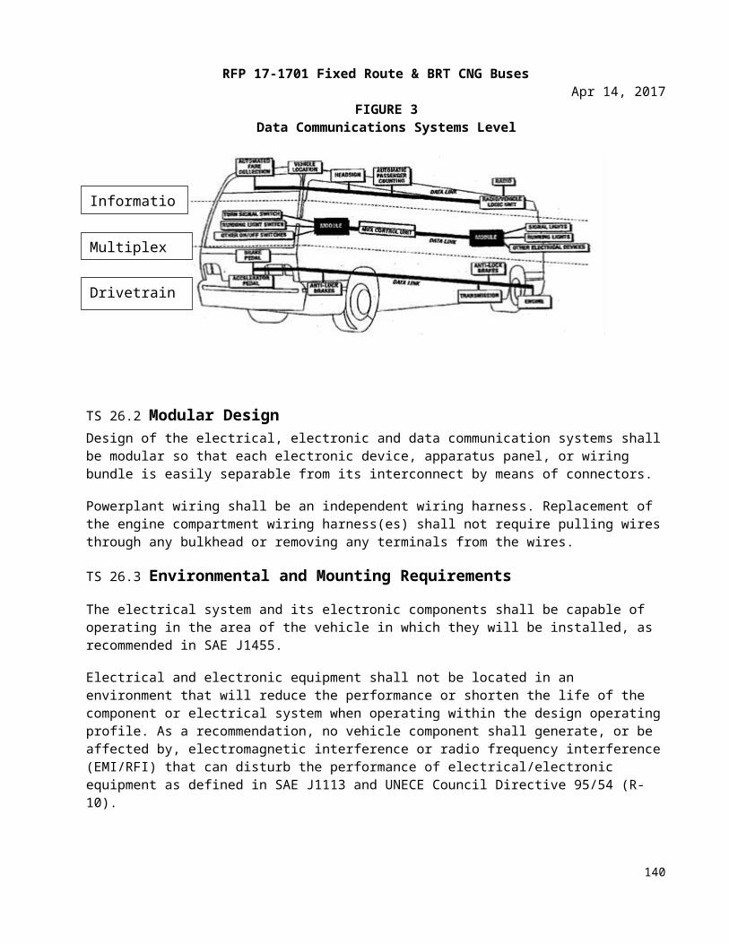
RFP 17-1701 Fixed Route & BRT CNG BusesApr 14, 2017
TS 44.5 Structure and DesignThe passenger seat frame and its supporting structure shall be constructed and mounted so that space under the seat is maximized and is completely free of obstructions to facilitate cleaning.
Seats, structures, and restraints around the securement area should not infringe into the mobility device envelope or maneuverability.
The transverse seat structure shall be fully cantilevered from the sidewall with sufficient strength for the intended service. The lowest part of the seat assembly that is within 12 inches of the aisle shall be at least 10 inches above the floor.
In locations at which cantilevered installation is precluded by design and/or structure, other seat mounting may be allowed.
All transverse objects — including seat backs, modesty panels, and longitudinal seats — in front of forward-facing seats shall not impart a compressive load in excess of 1000 lbs. onto the femur of passengers ranging in size from a 5th-percentile female to a 95th-percentile male during a 10g deceleration of the bus. This deceleration shall peak at 0.05 to 0.015 seconds from initiation. Permanent deformation of the seat resulting from two 95th-percentile males striking the seat back during this 10g deceleration shall not exceed 2 inches, measured at the aisle side of the seat frame at height H. The seat back should not deflect more than 14 inches, measured at the top of the seat back, in a controlled manner to minimize passenger injury. Structural failure of any part of the seat or sidewall shall not introduce a laceration hazard.
The seat assembly shall withstand static vertical forces of 500 lbs. applied to the top of the seat cushion in each seating position with less than 1/4 inch permanent deformation in the seat or its mountings. The seat assembly shall withstand static horizontal forces of 500 lbs. evenly distributed along the top of the seat back with less than 1/4 inch permanent deformation in the seat or its mountings. The seat backs at the aisle position and at the window position shall withstand repeated impacts of two 40-lb sandbags without visible deterioration. One sandbag shall strike the front 40,000 times and the other sandbag shall strike the rear 40,000 times. Each sandbag shall be suspended on a 36-inch pendulum and shall strike the seat back 10,000 times each from distances of 6, 8, 10 and 12 inches. Seats at both seating positions shall withstand 4000 vertical drops of a 40-lb sandbag without visible deterioration. The sandbag shall be dropped 1000 times each from heights of 6, 8, 10 and 12 inches. Seat cushions shall withstand 100,000 randomly positioned 3½ inch drops of a squirming, 150-lb, smooth-surfaced, buttocks-shaped striker with only minimal wear on the seat covering and no failures to seat structure or cushion suspension components.
The back of each transverse seat shall incorporate a handhold no less than 7/8 inch in diameter for standees and seat access/egress. The handhold shall not be a safety hazard during severe decelerations. The handhold shall extend above the seat back near the aisle so that standees shall have a convenient vertical assist, no less than 4 inches long that may be grasped with the full hand. This handhold shall not cause a standee using this assist to interfere with a seated 50th-percentile male passenger. The handhold shall also be usable by a 5th-percentile female, as well as by larger passengers, to assist with seat access/egress foe either transverse seating position. The upper rear portion of the seat back and the seat back handhold immediately forward of transverse seats shall be padded and/or constructed of energy absorbing materials. During a 10g deceleration of the bus, the HIC number (as defined by SAE Standard J211a) shall not exceed 400 for passengers ranging in size from a 5th percentile female through a 95th percentile male.
140
RFP 17-1701 Fixed Route & BRT CNG BusesApr 14, 2017
The seat back handhold may be deleted from seats that do not have another transverse seat directly behind and where a vertical assist is provided.
Longitudinal seats shall be the same general design as transverse seats but without seat back handholds. Longitudinal seats may be mounted on the wheelhouses. Armrests shall be included on the ends of each set of longitudinal seats except on the forward end of a seat set that is immediately to the rear of a transverse seat, the operator’s barrier, or a modesty panel, when these fixtures perform the function of restraining passengers from sliding forward off the seat. Armrests are not required on longitudinal seats located in the wheelchair parking area that fold up when the armrest on the adjacent fixed longitudinal seat is within 3½ inches of the end of the seat cushion. Armrests shall be located from 7 to 9 inches above the seat cushion surface. The area between the armrest and the seat cushion shall be closed by a barrier or panel. The top and sides of the armrests shall have a minimum width of 1 inch and shall be free from sharp protrusions that form a safety hazard.
Seat back handhold and armrests shall withstand static horizontal and vertical forces of 250 lbs. applied anywhere along their length with less than 1/4 inch permanent deformation. Seat back handhold and armrests shall withstand 25,000 impacts in each direction of a horizontal force of 125 lbs. with less than 1/4 inch permanent deformation and without visible deterioration.
TS 44.6 Construction & MaterialsSelected materials shall minimize damage from vandalism and shall reduce cleaning time. The seats shall be attached to the frame with tamper-resistant fasteners. Coloring shall be consistent throughout the seat ma-terial, with no visually exposed portion painted. Any exposed metal touching the sides or the floor of the bus shall be stainless steel. The seat, pads, and cushions shall be contoured for individuality, lateral support, and maximum comfort and shall fit the framework to reduce exposed edges.
The minimum radius of any part of the seat back, handhold, or modesty panel in the head or chest impact zone shall be a nominal 1/4 inch. The seat back and seat back handhold immediately forward of transverse seats shall be constructed of energy-absorbing materials to provide passenger protection and, in a severe crash, allow the passenger to deform the seating materials in the impact areas. Complete seat assemblies shall be interchangeable to the extent practicable. Agency to select seat fabric.
TS 44.7 Passenger AssistsPassenger assists in the form of full grip, vertical stanchions or handholds shall be provided for the safety of standees and for ingress/egress. Passenger assists shall be convenient in location, shape, and size for both the 95th-percentile male and the 5th-percentile female standee. Starting from the entrance door and mov-ing anywhere in the bus and out the exit door, a vertical assist shall be provided either as the vertical portion of seat back assist or as a separate item so that a 5th-percentile female passenger may easily move from one assist to another using one hand and the other without losing support. All stanchions shall be Stainless steel finish.
As an option, yellow powder coated stanchions will be made available and priced separately.
TS 44.8 AssistsExcluding those mounted on the seats and doors, the assists shall have a cross-sectional diameter between 1¼ and 1½ inches or shall provide an equivalent gripping surface with no corner radii less than 1/4 inch. All passenger assists shall permit a full hand grip with no less than 1½ inches of knuckle clearance around the
141
RFP 17-1701 Fixed Route & BRT CNG BusesApr 14, 2017
assist. Passenger assists shall be designed to minimize catching or snagging of clothes or personal items and shall be capable of passing the NHTSA Drawstring Test.
Any joints in the assist structure shall be underneath supporting brackets and securely clamped to prevent passengers from moving or twisting the assists. Seat handholds may be of the same construction and finish as the seat frame. Door mounted passenger assists shall be of anodized aluminum, stainless steel, or pow-der-coated metal. Connecting tees and angles may be powder-coated metal castings. Assists shall withstand a force of 300 lbs. applied over a 12 inch lineal dimension in any direction normal to the assist without per-manent visible deformation. All passenger assist components, including brackets, clamps, screw heads, and other fasteners used on the passenger assists shall be designed to eliminate pinching, snagging, and cutting hazards and shall be free from burrs or rough edges.
TS 44.9 Front DoorwayFront doors, or the entry area, shall be fitted with ADA-compliant assists. Assists shall be as far outward as practicable, but shall be located no farther inboard than 6 in. from the outside edge of the entrance step and shall be easily grasped by a 5th-percentile female boarding from street level. Door assists shall be functionally continuous with the horizontal front passenger assist and the vertical assist and the assists on the wheel housing or on the front modesty panel.
TS 44.10 VestibuleThe aisle side of the Operator’s barrier, the wheel housings, and when applicable the modesty panels shall be fitted with vertical passenger assists that are functionally continuous with the overhead assist and that extend to within 36 in. of the floor. These assists shall have sufficient clearance from the barrier to prevent inadvertent wedging of a passenger’s arm.
A horizontal passenger assist shall be located across the front of the bus and shall prevent passengers from sustaining injuries on the fare collection device or windshield in the event of a sudden deceleration. Without restricting the vestibule space, the assist shall provide support for a boarding passenger from the front door through the fare collection procedure. The assist shall be no less than 36 inches above the floor. The assists at the front of the bus shall be arranged to permit a 5th-percentile female passenger to easily reach from the door assist, to the front assist, to vertical assists on the operator’s barrier, wheel housings, or front modesty panel.
TS 44.11 Rear Doorway(s)Vertical assists that are functionally continuous with the overhead assist shall be provided at the aisle side of the transverse seat immediately forward of the rear door and on the aisle side of the rear door modesty panel(s). Passenger assists shall be provided on modesty panels that are functionally continuous with the rear door assists. Rear doors, or the exit area, shall be fitted with assists having a cross-sectional diameter between 1¼ and 1½ inches or providing an equivalent gripping surface with no corner radii less than 1/4 inch, and shall provide at least 1½ inches of knuckle clearance between the assists and their mounting. The assists shall be designed to permit a 5th-percentile female to easily move from one assist to another during the entire exiting process. The assists shall be located no farther inboard than 6 inches from the outside edge of the rear doorway step.
142
RFP 17-1701 Fixed Route & BRT CNG BusesApr 14, 2017
TS 44.12 OverheadExcept forward of the standee line and at the rear door, a continuous, full grip, overhead assist shall be provided. This assist shall be located over the center of the aisle seating position of the transverse seats. The assist shall be no less than 70 inches above the floor.
There shall be fourteen (14) vinyl coated nylon grab straps (35’ and 40’ bus) and ten (10) on (30’ bus) positioned throughout the bus interior mounted to the horizontal stanchions.
Overhead assists shall simultaneously support 150 lbs. on any 12-inch length. No more than 5 percent of the full grip feature shall be lost due to assist supports.
TS 44.13 Longitudinal Seat AssistsLongitudinal seats shall have vertical assists located between every other designated seating position, ex-cept for seats that fold/flip up to accommodate wheelchair securement. Assists shall extend from near the leading edge of the seat and shall be functionally continuous with the overhead assist. Assists shall be stag-gered across the aisle from each other where practicable and shall be no more than 52 inches apart or func-tionally continuous for a 5th percentile female passenger.
TS 44.14 Wheel Housing Barriers/AssistsUnless passenger seating is provided on top of wheel housing, passenger assists shall be mounted around the exposed sides of the wheel housings which shall also be designed to prevent passengers from sitting on wheel housings. Such passenger assists shall also effectively retain items, such as bags and luggage, placed on top of wheel housing.
TS 44.15 Passenger DoorsThe front door shall be a "slide glide" type inward opening, operator controlled, of corrosion-resistant construction. Minimum clear opening shall be 31.75” inches. The front door shall have a minimum height of 78 inches. The overhead clearance between the top of the door opening and the highest point of the ramp shall be a minimum of 68 inches. The step height shall not exceed 16.5 inches at either doorway without kneeling and shall not exceed 15.5 inches at the step. A maximum of two steps is allowed to accommodate a raised aisle floor in the rear of the bus.
Operation of, and power to, the front door shall be controlled by the operator. Door shall be opened completely in 1 to 3.5 seconds from the time of control actuation, and shall be subject to adjustment requirements of this specification. A control valve in the operator’s compartment shall shut off the power to, and/or dump the power from, the front door mechanism to permit manual operation of the front door with the bus shut down.
The rear or exit door shall be a two panel swing out type designed to provide a minimum clear opening of 30 inches panel to panel and a minimum height of 78 inches. Rear doors shall be operator opened and spring closed. The closing of the door shall begin after the control has been moved to the closed position, and after the door has been fully opened. Door opening and closing speeds shall be adjustable. The rear door shall be equipped with a sensitive edge which will open the door automatically if an object is trapped between the doors.
The doors shall have handrails (1.25 inches or equivalent surface area with a 1.50 inches knuckle clearance) mounted on the door panels and/or a modesty panel in the door well/step well. The clear opening
143
RFP 17-1701 Fixed Route & BRT CNG BusesApr 14, 2017
dimension shall apply inside these handrails. Handrails whether on the door panel or in the body, shall be part of the systematic set of passenger assists.
To preclude movement of the bus, an accelerator interlock shall lock the accelerator in the closed position and a brake interlock shall engage the rear axle service brake system when the front and rear door control is activated and the vehicle is moving below 3 mph. When vehicle is moving above 3 mph the rear door shall remain locked. The braking effort shall be to the maximum capability of the rear axle brakes.
As an option, the Vapor V-Touch control system will be made available and priced separately.
As an option, the Vapor CLASS control system will be made available and priced separately.
Locked doors shall require a force of more than 200 lbs. to open manually. When the locked doors are manually forced to open, damage shall be limited to the bending of minor door linkage with no resulting damage to the doors, actuators or complex mechanism.
As an option, bi-parting Plug type rear doors driven by a single differential door engine manufactured by Vapor Bus International shall be made available and priced separately. This door engine shall be controlled by three-way “poppet type” solenoid valves. The use of four way valves, double solenoid valves or “spool type valves” shall not be allowed.
TS 44.16 Rear Door interlocks See “Hardware Mounting” for door system interlock requirements.
TS 44.17 Emergency OperationIn the event of an emergency, it shall be possible to manually open doors designated as emergency exits from inside the bus using a force of no more than 25 lbs. after actuating an unlocking device. The unlocking device shall be clearly marked as an emergency-only device and shall require two distinct actions to actuate. The respective door emergency unlocking device shall be accessible from the doorway area. The unlocking device shall be easily reset by the operator without special tools or opening the door mechanism enclosure. Doors that are required to be classified as “Emergency Exits” shall meet the requirements of FMVSS 217.
TS 44.18 Door ControlThe door control shall be located in the operator’s area within the hand reach envelope described in SAE Recommended Practice J287, “Operator Hand Control Reach.” The operator’s door control shall provide tactile feedback to indicate commanded door position and resist inadvertent door actuation.
TS 45. Door ControllerTS 45.1 Five-Position Operator’s Door ControllerThe control device shall be protected from moisture. Mounting and location of the door control device han-dle shall be designed so that it is within comfortable, easy arm’s reach of the seated operator. The door con-trol device handle shall be free from interference by other equipment and have adequate clearance so as not to create a pinching hazard.
Position of the door control handle shall result in the following operation of the front and rear doors:i. Center position: Front door closed, rear door(s) closed or set to lock.
144
RFP 17-1701 Fixed Route & BRT CNG BusesApr 14, 2017
ii. First position forward: Front door open, rear door(s) closed or set to lock.iii. Second position forward: Front door open, rear door(s) open or set to open.Iv. First position back: Front door closed, rear door(s) open or set to open.v. Second position back: Front door open, rear door(s) open or set to open.
TS 45.2 Loading SystemsThe bus shall be equipped with a front door Lift –U LU 18 ramp mechanism that conforms to all require-ments of the Americans with Disabilities Act (ADA). It is to be an all electrically operated system which will assume the normal entrance configuration when stowed. When stowed, the ramp should not exceed any of the normal bus undercarriage clearances. All ramp components and mechanisms shall be constructed of cor-rosion resistant materials and incorporate a design which affords maximum protection from the elements during normal bus operations. Ease of maintenance and servicing shall be a prime consideration in system design and construction.
The wheelchair ramp shall have a manual release, deploy, and stow mechanism. The components involved with manual operation shall be completely accessible. If ramp provides for a nylon strap, it must be located on the forward side of the ramp to preclude a trip hazard.
The ramp shall be controlled by toggle switches, master on-off, up-down, and stow-deploy. The control switches shall be of the spring loaded to a safe position type so that constant manual pressure is required by the operator during ramp operation. All controls shall be clearly identified by function and present a reason-ably foolproof and natural sequence of operation.
Visual and audible warning devices shall be located immediately to the rear of the front door. The audible warning device shall be activated only when the ramp is functioning. Interlocking and fast idle provisions shall be incorporated so the ramp cannot be extended unless the entrance door is in the full open position, the transmission in neutral, and the parking brake engaged. The entrance door cannot be closed unless the ramp is in the fully stowed position. The bus service brakes shall be automatically applied when the ramp is in any position other than the stowed and locked position. All ramp components mounted under the bus shall be protected from dirt, debris, and road splash through the use of appropriate enclosures, mud flaps, or sealed compartments, subject to approval by each Procuring Agency.
Weatherproof access panels/doors shall be provided to allow for servicing and troubleshooting both ramp and under-floor bus components. Lubing the ramp shall be accomplished without removing the belly pan. The electrical interfacing connections between the bus and the ramp shall be of the quick disconnect type to facilitate ramp removal and installation.
TS 45.3 Two Forward-Facing Wheelchair Securement LocationsTwo forward-facing locations, as close to the wheelchair loading system as practical, shall provide parking space and securement system compliant with ADA requirements for a passenger in a wheelchair.
TS 45.4 Wheelchair Securing SystemThe wheelchair securement shall be the American Seating Q-pod in both positions on the 35’ bus and the American Seating Q-pod(curbside) and the Quantum(streetside) on the 40’ bus. At a minimum, all restraint systems must meet C.F.R. 49, FMVSS, FTA and ADA standards.
145
RFP 17-1701 Fixed Route & BRT CNG BusesApr 14, 2017
As an option the American Seating Reliant system and 4ONE V-Pro, Q’Straint Belts and Retractors will be made available and priced separately.
SIGNAGE AND COMMUNICATIONTS 46. SIGNAGE & COMMUNICATIONSTS 46.1 Destination Signs A Hanover all LED Amber automatic electronic destination sign system shall be furnished and installed in each bus by the manufacturer. The destination sign system shall consist of:
(1) One (1) Front sign 17 rows x 160 columns; display height minimum 7.9 inches, display width 63 inches, or a 24 rows x 200 columns sign.
(2) One (1) Side sign, on the curb side, 15 rows x 112 columns; display height minimum 4.2 inches, display width 42 inches.
(3) One (1) Rear sign 15 rows x 48 without w/c sign.
(4) Operators Control Unit (OCU)
As an option, white (Silver) LED light sign system will be made available and be priced separately.
TS 46.2 Cables and AccessoriesThe Front Sign shall be mounted on the front of the Bus, near the top edge of the body, behind windshield protection, and in an enclosed but accessible compartment. The Side Sign shall be located on the right side (curb side) of the bus near the front door, mounted near the top of an existing window. The Rear Sign (external) shall be mounted on the rear of the vehicle on an appropriate sized cutout.
The entire display area of all signs shall be readable in direct sunlight, at night, and in all lighting conditions between those two lighting extremes, with evenly distributed illumination appearance to the un-aided eye.
The system shall be microprocessor-based; utilizing approved bi-directional serial communications, such as SAE J1708 or IBIS, EIA RS-485, between system components, and shall utilize error detection techniques within the communication protocol.
Independent Controller Boards shall be mounted in the front and side destination Sign. The system shall be capable of communicating with additional information devices, such as interior information Signs, Voice Annunciation devices, fare box, etc. The system shall provide for destination and/or Public Relations (P/R) message entry.
Flash memory integrated circuits shall be capable of storing and displaying up to 10,000 message lines. Message memory shall be changeable by the use of a USB/9 pin key fob device of not less than one (1) megabyte memory capacity but sized according to the message listing noted herein.
The System shall have the ability to sequentially display multi-line destination messages, with the route number portion remaining in a constant “on” mode at all times, if so programmed. It shall also be capable of accepting manual entry of Route Alpha/Numeric information on any/all signs.
146
RFP 17-1701 Fixed Route & BRT CNG BusesApr 14, 2017
The various Signs shall be programmable to display independent messages or the same messages; up to two destination messages and one public relations message shall be pre-selectable. The operator shall be able to quickly change between the pre-selected messages without re-entering a message code. Public relations messages shall be capable of being displayed alternately with the regular text and route messages or displayed separately.
An emergency message shall be activated by a push button or toggle switch. The emergency message shall be displayed on signs facing outside the vehicle while signs inside the vehicle, including the OCU display, remain unchanged. The emergency message shall be canceled by entering a new destination code, or power cycling (after removal of the emergency signal).
The programming software shall provide means of adjusting the length of time messages are displayed in 0.1 second increments up to twenty-five seconds.
Power to the Sign system shall be controlled by the Master Bus Run Switch. The signs shall operate in all positions of this switch except off. The signs shall be internally protected against voltage transients and RFI interference to ensure proper operation in the local environment.
TS 46.3 Display and Display IlluminationAll Sign displays shall consist of pixels utilizing High Intensity Light Emitting Diodes (“LED”), for superior outdoor environmental performance, (of Amber illumination appearance of light wavelength of 590 NM). LED should be made of AllnGaP II, superior UV resistant Epoxy lens and superior resistance to the effects of moisture. Each pixel shall have a dedicated LED for illumination of that pixel in all lighting conditions. The sign system shall have multi-level intensity changes, which adjust automatically as a function of ambient lighting conditions. There shall be no requirement for any fan or any specialized cooling or air circulation.
This LED shall be mounted such as to be visible directly to the observer positioned in the viewing cone, allowing for full readability 65 degrees either side of the destination sign centerline. The LEDs shall be the only means of illumination of the sign system. The LED illumination source shall have an operating life M.T.B.F. of not less than 100,000 hours. Each LED shall not consume more than 0.02 Watts.
The characters formed by the System shall meet the requirements of the Americans with Disabilities Act (ADA) of 1990 Reference 49 C.F.R. Section 38.39.
TS 46.4 Sign EnclosuresAll Signs shall be enclosed in a manner such as to inhibit entry of dirt, dust, water, and other contaminants during normal operation or cleaning. Access shall be provided to clean the inside of the bus window(s) associated with the Sign and to remove or replace the Sign components. Access panels and display boards shall be mounted for ease of maintenance/replacement. Any exterior Rear Sign enclosure used shall be made of Polycarbonate material containing fiberglass reinforcement. The vehicle manufacturer shall comply with the Sign manufacturer's recommended mounting, mounting configuration, and installation procedures to assure optimum visibility and service accessibility of the Sign System and System components.
TS 46.5 Electronic System RequirementsAll electronic circuit boards used in the Sign System shall be conformal coated. All Sign System components shall be certified to have been subjected to a "burn-in" test of a minimum of twelve (12) hours operation in a temperature of 150ºF prior to final inspection.
147
RFP 17-1701 Fixed Route & BRT CNG BusesApr 14, 2017
TS 46.6 Operator Control Unit (OCU)The OCU Unit shall be used to view and update display messages. It shall be recess mounted on the Bus vehicle front Sign compartment access cover or door. The OCU shall utilize a multi-key conductive flexible keypad and be designed for transit operating conditions. Other mounting locations for the OCU shall be made available, with selection made at the pre-production meeting.
Only one switch is required to activate the 3 systems (radio, surveillance, and sign.) Integration is required if the Twin Vision Sign and the Digital Recorders Talking Bus System are selected with a single OCU to control both systems.
The OCU Unit shall contain a display of at least two-lines of 20-character capability. The OCU Unit shall contain an audio annunciation that beeps indicating that a key is depressed. The OCU Unit shall continuously display the message associated with the selected destination readings (except the emergency message feature as noted above).
If the IBIS interface is required in the Destination Sign System, an auxiliary RS232 (DB9) port shall be made optionally available on the OCU under frame for inputs from any wireless technology that might be envisioned in the future. This auxiliary RS232 port shall operate at 9600 baud and accept commands from a wireless source (such as Spread Spectrum receivers) and will set destination sign addresses as if manually operated by the OCU operator.
If the J1708 interface is selected for the Destination Sign System, an auxiliary J1708 port shall be made available on the J1708 OCU so that auxiliary J1708 commands may be provided to the Destination Sign system from a wireless source that conforms to the J1708 command structure.
148
RFP 17-1701 Fixed Route & BRT CNG BusesApr 14, 2017
TS 47. Passenger Information and AdvertisingTS 47.1 Interior DisplaysAdvertising media 11 inches high and 0.09 inch thick shall be retained near the juncture of the bus ceiling and sidewall. The retainers may be concave and shall support the media without adhesives. The media shall be illuminated by the interior light system.
TS 47.2 Passenger Stop Request/Exit SignalThe ambulatory passenger signal shall be clear pull cords conveniently located so standing and seated passengers can easily reach it, this includes down the mullions. The pull cords shall be accessible from the exit door area. There shall be a lighted display sign which indicates "STOP REQUESTED" when the signal is activated. The signal chime shall operate once, and the sign shall light and remain lit with the chime disabled until the next stop when the front doors or rear doors have been opened, resetting the system.There shall be a second passenger signal of a different tone that meets the ADA requirements mounted to the bottom of the flip seat for the mobility aid users to alert the operator when a mobility aid user wishes to disembark. One such system that meets these minimum requirements is the Tape Switch Corp. 3.5” x 7” yellow push pad. There shall be two lights on the operator’s front dash that indicate when an ambulatory or non-ambulatory passenger wishes to disembark.
TS 47.3 Communications - Video Surveillance SystemA Seon Explorer DX-HD video surveillance system shall be required. The system will require 8 internal and 2 external camera locations. The DVR shall have GPS, a 1 terabyte hard drive, an impact sensor and be mounted in a secured electrical cabinet. The GPS antenna shall be roof mounted. An event/status indicator switch shall be located on the left side of the operator’s dash.
TS 47.4 Mobile Radio SystemA separate electrical circuit protected with the circuit breaker shall be provided to the radio transceiver location. The radio circuit shall be connected and placed to minimize electrical noise and transients.
A Motorola APX 4500 with silent alarm switch and external speaker shall be provided.
TS 47.5 Electronics/Equipment CompartmentEach bus shall be equipped a fully sealed compartment located on the left front wheelhouse to provide a mounting location for radio equipment, video recording equipment, APC equipment, and other electronic equipment. The compartment shall be lockable, completely water resistant, and of steel construction. It shall be accessible from inside the bus, shall have 3 slide trays that automatically lock into place for easy maintenance of the equipment. The compartment shall be water resistant when the service door is secured. The compartment shall be supplied with power and ground circuit requirements.
149
RFP 17-1701 Fixed Route & BRT CNG BusesApr 14, 2017
A location convenient to the operator shall be provided for the radio control head, speaker, and handset. The antenna mounting and lead termination shall be accessible from the bus interior. Conduit shall lead to the radio compartment and shall have a minimum bend radius adequate for easy pulling of coaxial cable. An access plate shall be provided in the ceiling. The compartment door shall have a lock. A sealing provision (gasket) shall be incorporated in the door of this compartment. The radio compartment finish shall be powder coated Grey, standard grey, or agency designated color.
TS 47.6 Radio MountingA suitable area shall be provided for the mounting of communication Radio. This mounting could range from a simple plate to a box to contain the radio. A factor governing the mounting of the radio is what space is available. Another provision is that the cable that connects the radio and control head switch must be routed to an area immediately accessible to the operator.
TS 47.7 Radio TransmitterA Radio control head and speaker mounting plate shall be installed in a location to provide easy access for operator operation. The hand set shall be hand held and be equipped with a cradle harness. All switches and controls shall be permanently and clearly labeled.
TS 47.8 AntennaA single antenna will be mounted on the roof of each bus that will accommodate RF/GPS/Cellular. This antenna shall be located as close to midpoint between the two sides as practical, but not on a seam, and as close to the area of the radio, as to preclude a long run of coaxial cable that connects the radio and the antenna, so as to provide access below, should the antenna ever need to be changed.
TS 47.9 Voice Annunciation and ITS A REI public announcement system configured independent from the bus radio system with 8 internal and 2 external speakers, auxiliary input, a hand held microphone, and volume control mounted on the dash will be provided. Manufacturer to install pre-wiring only without component installation, to power and connect an AVA device of Tulsa Transit’s choice.
TS 47.10 Automatic Passenger Counting (APC)Tulsa Transit is in the process of procuring an APC system that will be deployed on a portion of the current fleet and all of the BRT vehicles. The details of the system will not be known until the procurement is complete. The requirement is to provide wiring for the APC detectors that will be located at the front door and the rear door to a location in the equipment cabinet. APC hardware will be installed by the bus manufacturer as well. Additional details on these requirements will be provided when available from the APC vendor.
TS 47.11 Traffic Signal Priority (TSP)
150
RFP 17-1701 Fixed Route & BRT CNG BusesApr 14, 2017
Manufacturer to install pre-wiring only without component installation, to power TSP communications device of Tulsa Transit’s choice.
SECTION 7: WARRANTY REQUIREMENTS
BASIC PROVISIONSWR 1. Warranty RequirementsWR 1.1 Contractor WarrantyWarranties in this document are in addition to any statutory remedies or warranties imposed on the Contractor. Consistent with this requirement, the Contractor warrants and guarantees to Tulsa Transit each complete bus and specific subsystems and components as follows. Performance requirements based on design criteria shall not be deemed a warranty item.
WR 1.2 Complete BusThe complete bus, propulsion system, components, major subsystems and body and chassis structure are warranted to be free from Defects and Related Defects for one year or 75,000 miles, whichever comes first, beginning on the date of revenue service but not longer than 30 days after acceptance under “Inspection, Testing and Acceptance.” The warranty is based on regular operation of the bus under the operating conditions prevailing in Tulsa Transit’s locale.
WR 1.3 Body and Chassis StructureBody, body structure, structural elements of the suspension and engine cradle is warranted to be free from Defects and Related Defects for three years or 150,000 miles, whichever comes first.
Primary load-carrying members of the bus structure, including structural elements of the suspension, are warranted against corrosion failure and/or Fatigue Failure sufficient to cause a Class 1 or Class 2 Failure for a period of seven (7) years or 350,000 miles, whichever comes first.
WR 1.4 Propulsion SystemPropulsion system components, specifically the engine, transmission or drive motors, and generators (for hybrid technology) and drive and non-drive axles shall be warranted to be free from Defects and Related Defects for the standard two years or 100,000 miles, whichever comes first. An Extended Warranty may be purchased at an additional cost. The propulsion system manufacturer’s standard warranty, delineating items excluded from the Extended Warranty, submitted in accordance with the Request for Pre-Offer Change or Approved Equal or with the Form for Proposal Deviation.
WR 1.5 Emission Control System (ECS)The Contractor warrants the emission control system for five years or 100,000 miles, whichever comes first. The ECS shall include, but is not limited to, the following components:
• complete exhaust system, including catalytic converter (if required)• components identified as emission control devices
151
RFP 17-1701 Fixed Route & BRT CNG BusesApr 14, 2017
WR 1.6 SubsystemsOther subsystems shall be warranted to be free from Defects and Related Defects for one year or 100,000 miles, whichever comes first. Other subsystems are listed below:
• AC unit and compressor: Roof and/or rear main unit only, excluding floor heaters and front defroster.
WR 1.7 Serial NumbersUpon delivery of each bus, the Contractor shall provide a complete electronic list of serialized units installed on each bus to facilitate warranty tracking. The list shall include, but is not limited to:
• engine• transmission• starter• A/C compressor and condenser/evaporator unit• drive axle• wheelchair ramp (if applicable)
The Contractor shall provide updated serial numbers resulting from warranty campaigns. The format of the list shall be approved by Tulsa Transit prior to delivery of the first production bus.
WR 1.8 Extension of WarrantyIf, during the warranty period, repairs or modifications on any bus are made necessary by defective design, materials or workmanship but are not completed due to lack of material or inability to provide the proper repair for thirty (30) calendar days, the applicable warranty period shall be extended by the number of days equal to the delay period.
WR 1.9 Superior WarrantyThe Contractor shall pass on to Tulsa Transit any warranty offered by a component Supplier that is superior to that required herein. The Contractor shall provide a list to Tulsa Transit noting the conditions and limitations of the Superior Warranty not later than the start of production. The Superior Warranty shall not be administered by the Contractor.
WR 2. Repair ProceduresWR 2.1 Repairs by Tulsa Transit WR 2.1.1 Parts UsedIf Tulsa Transit performs the warranty-covered repairs, it shall correct or repair the defect and any related defects utilizing parts supplied by the Contractor specifically for this repair. At its discretion, Tulsa Transit may use Contractor-specified parts available from its own stock if deemed in its best interests.
WR 2.1.2 Contractor-Supplied PartsTulsa Transit may require that the Contractor supply parts for warranty-covered repairs being performed by Tulsa Transit. Those parts may be remanufactured but shall have the same form, fit and function, and warranty. The parts shall be shipped prepaid to Tulsa Transit from any source selected by the Contractor
152
RFP 17-1701 Fixed Route & BRT CNG BusesApr 14, 2017
within three (3) days of receipt of the request for said parts and shall not be subject to a Tulsa Transit handling charge.
WR 2.1.3 Defective Component ReturnThe Contractor may request that parts covered by the warranty be returned to the manufacturing plant. The freight costs for this action shall be paid by the Contractor. Materials should be returned in accordance with the procedures outlined in “Warranty Processing Procedures.”
WR 2.1.4 Reimbursement for Labor and Other Related CostsTulsa Transit shall be reimbursed by the Contractor for labor. The amount shall be determined by Tulsa Transit for a qualified mechanic at a straight time wage rate of $55.00 per hour, which includes fringe benefits and overhead adjusted for Tulsa Transit’s most recently published rate in effect at the time the Work is performed, plus the cost of towing the bus if such action was necessary and if the bus was in the normal service area. These wage and fringe benefit rates shall not exceed the rates in effect in Tulsa Transit’s service garage at the time the defect correction is made.
WR 2.1.5 Reimbursement for PartsTulsa Transit shall be reimbursed by the Contractor for defective parts and for parts that must be replaced to correct the defect. The reimbursement shall be at the current price at the time of repair and shall include taxes where applicable, plus fifteen (15) percent handling costs. Handling costs shall not be paid if part is supplied by Contractor and shipped to Tulsa Transit.
WR 2.1.6 Reimbursement RequirementsThe Contractor shall respond to the warranty claim with an accept/reject decision including necessary failure analysis no later than sixty (60) days after Tulsa Transit submits the claim and defective part(s), when requested. Reimbursement for all accepted claims shall occur no later than sixty (60) days from the date of acceptance of a valid claim. Tulsa Transit may dispute rejected claims or claims for which the Contractor did not reimburse the full amount. The parties agree to review disputed warranty claims during the following quarter to reach an equitable decision to permit the disputed claim to be resolved and closed. The parties also agree to review all claims at least once per quarter throughout the entire warranty period to ensure that open claims are being tracked and properly dispositioned.
WR 2.2 Warranty after Replacement/Repairs If any component, unit or subsystem is repaired, rebuilt or replaced by the Contractor or by Tulsa Transit with the concurrence of the Contractor, the component, unit or subsystem shall have the unexpired warranty period of the original. Repairs shall not be warranted if the Contractor-provided or authorized parts are not used for the repair, unless the Contractor has failed to respond within five days, in accordance with “Repairs by the Contractor.”
If an item is declared to be a Fleet Defect, the warranty stops with the declaration of the Fleet Defect. Once the Fleet Defect is corrected, the item(s) shall have three (3) months or remaining time and/or miles of the original warranty, whichever is greater. This remaining warranty period shall begin on the repair/replacement date for corrected items on each bus if the repairs are completed by the Contractor or on the date the Contractor provides all parts to Tulsa Transit.
153
RFP 17-1701 Fixed Route & BRT CNG BusesApr 14, 2017
WR 2.3 Reimbursements Reimbursements are to be transmitted to the following address.
Tulsa Transit510 S. RockfordTulsa, OK 74120
154
RFP 17-1701 Fixed Route & BRT CNG BusesApr 14, 2017
SECTION 8: QUALITY ASSURANCE
QA 1. Contractor’s In-Plant Quality Assurance RequirementsContractor shall establish and maintain an effective in-plant quality assurance organization. It shall be a specifically defined organization and should be directly responsible to the Contractor’s top management.
QA 2. ISO 9001:2000 CertificationQuality control during the manufacture of the buses as specified is of critical importance to Tulsa Transit. It is the intent of Tulsa Transit to procure transit buses from a manufacturer that has a proven and third party certified quality control system in place. As such, the bus manufacturer shall be certified ISO 9001:2000 at the facility(s) which produce Tulsa Transit’s buses. Written certification of ISO 9001:2000 or 2009 update compliance is required with the Proposal submission documents. Failure to provide the certification as specified will render the Proposal non-responsive and cause the rejection of the Contractor’s Proposal.
155
RFP 17-1701 Fixed Route & BRT CNG BusesApr 14, 2017
SECTION 9: FORMS AND CERTIFICATIONS
CER 1. Proposer’s ChecklistRFP 17-1701 Fixed Route & BRT CNG Buses
Package 1: Technical Proposal□ 1. Letter of Transmittal□ 2. Technical Proposal□ 3. Acknowledgement of Addenda□ 4. Form for Proposal Deviation□ 5. Vehicle Questionnaire□ 6. References and non-priced information (if provided by Proposer)□ 7. Engineering organization chart, engineering change control procedure, field modification
process□ 8. Manufacturing facility plant layout, other contracts, staffing□ 9. Production schedule and other Contract commitments for the duration of this Contract.□ 10. Quality Assurance Program
Package 2: Price Proposal□ 1. Letter of Transmittal□ 2. Pricing Schedule (including option buses, spare parts package, engineering, manuals, training,
special tools and test equipment)
Package 3: Qualifications Package□ 1. Pre-Award Evaluation Data Form□ 2. A copy of the three (3) most recent audited financial statements or a statement from the
Proposer regarding how financial information may be reviewed by Tulsa Transit□ 3. Letter for insurance□ 4. Letter for performance bond (if applicable)□ 5. Letter of commitment for parental financial guarantee (if applicable)□ 6. Proposal Form
Package 4: Proprietary/Confidential Information Package1□ 1. Proprietary/Confidential Information
1. There may be items in the first three packages that are included in Package 4 because they are considered to be proprietary/confidential information. When this occurs, the Proposer must note that fact in Packages 1 through 3.
156
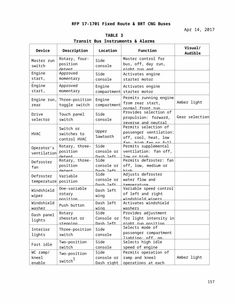
RFP 17-1701 Fixed Route & BRT CNG BusesApr 14, 2017
CER 2. Acknowledgement of AddendaFailure to acknowledge receipt of all addenda may cause the Proposal to be considered nonresponsive to the Solicitation. Acknowledged receipt of each addendum must be clearly established and included with the Proposal.
The undersigned acknowledges receipt of the following addenda to the documents:
Addendum No.: Dated:
Addendum No.: Dated:
Addendum No.: Dated:
Addendum No.: Dated:
Proposer:Name:Title:Phone:Street address:City, state, ZIP:
_____________________________________________________________________ _______________________Authorized signature Date
157
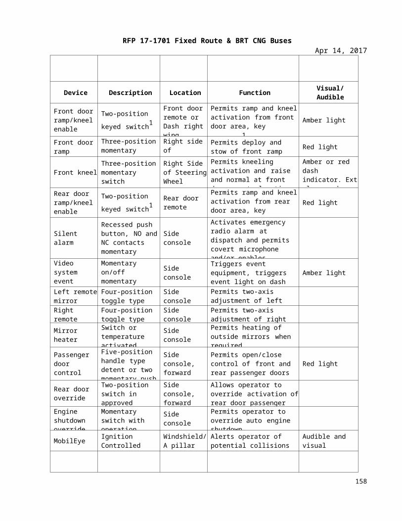
RFP 17-1701 Fixed Route & BRT CNG BusesApr 14, 2017
CER 3. Contractor Service and Parts Support Data
Location of nearest Technical Service Representative to Tulsa Transit
Name:Address:Telephone:Describe technical services readily available from said representative:
Location of nearest Parts Distribution Center to Tulsa Transit:
Name:Address:Telephone:Describe the extent of parts available at said center:
Policy for delivery of parts and components to be purchased for service and maintenance:
Regular method of shipment:Cost to Tulsa Transit:
158
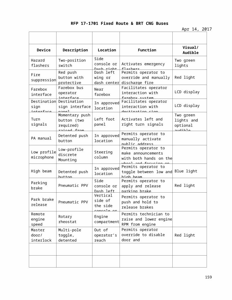
RFP 17-1701 Fixed Route & BRT CNG BusesApr 14, 2017
CER 4. REQUEST FOR EQUALSRETURN WITH YOUR PROPOSAL
Company Name:
Specification Section Number:
Component Item Listed:
Proposed Item:
Note: A separate form must be submitted for each request for an approved equal. Proposers are required to submit technical information for each item. Any request re-ceived without the necessary technical information will be returned.
159
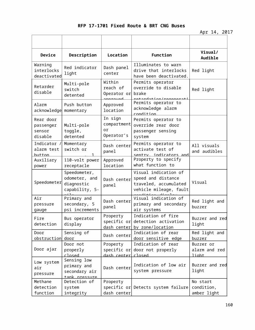
RFP 17-1701 Fixed Route & BRT CNG BusesApr 14, 2017
CER 5. Pricing ScheduleTulsa TransitRFP 17-1701 Fixed Route & BRT CNG Buses – Heavy Duty, 38-42 Passenger, 30, 35, and 40-Foot, CNG, Low Floor BusesAll prices FOB Tulsa, Oklahoma
Unit Price
Heavy Duty, 38-42 Passenger, 30-Foot, CNG, Low Floor Buses
Heavy Duty, 38-42 Passenger, 35-Foot, CNG, Low Floor Buses
Heavy Duty, 38-42 Passenger, 40-Foot, CNG, Low Floor Buses
Manuals Lump Sum
Training Lump Sum
TOTAL PROPOSED PRICE
GFI/Genfare Fastfare validating electronic fareboxes (including installation)
Diamond Model XV Farebox
Seon Design eight (8) cameral mobile surveillance system (including installation)
Training
Allison B 400R transmission
Electronic Transmission fluid level monitoring & protection system
FEMCO oil drain
Full length composite subfloor
Hydraulic Assisted steering
Brake stroke & wear monitoring system
Four (4) Group 31 Batteries
Niehoff 803 alternator
Adjustable brake/accelerator pedal
Recaro Ergo Metro w/3 pt seat belt. USSC 9100 ALX, USSC ALX 3, USSC G2
Silicone cushion for operators seat
160
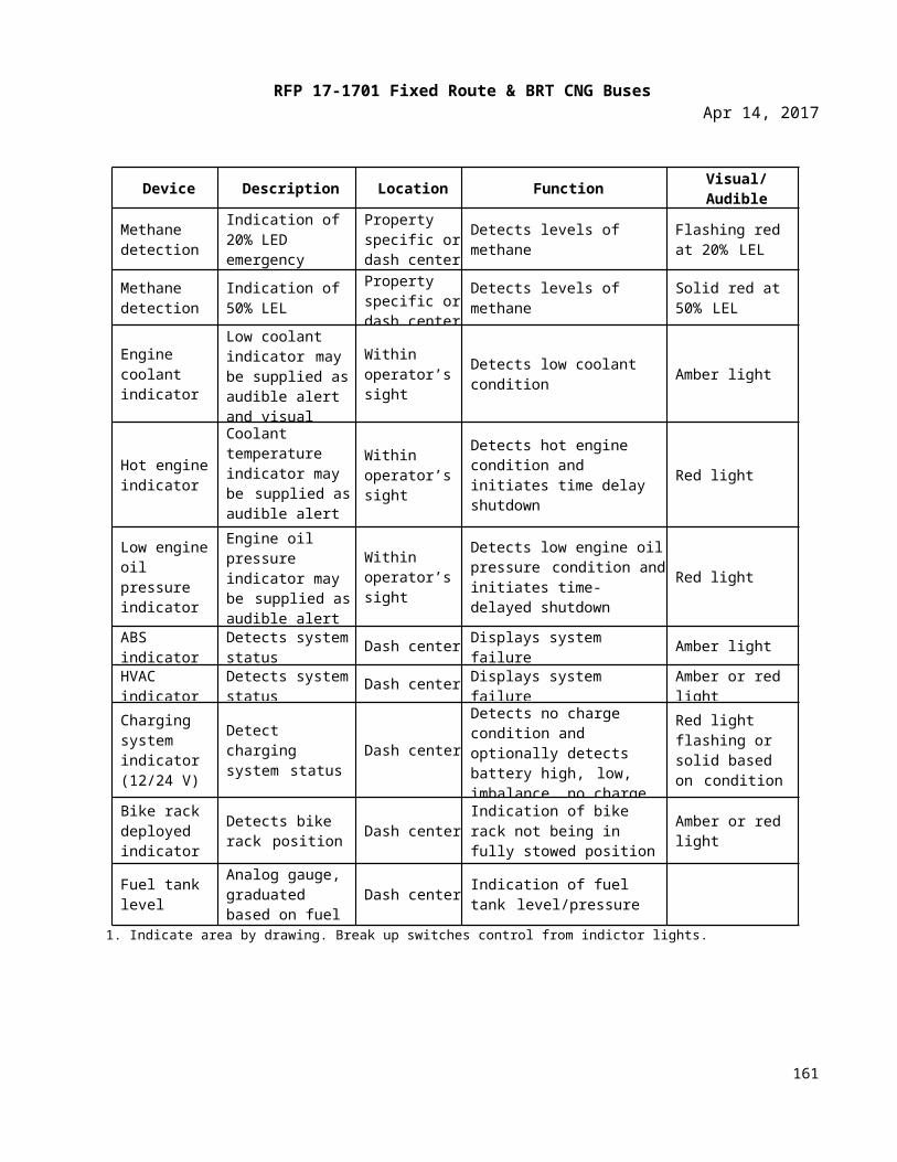
RFP 17-1701 Fixed Route & BRT CNG BusesApr 14, 2017
B&R 10” x 11” 2-piece flat & convex, heated, & remote w/ stainless steel and & aluminum arms
One piece windshield which incorporates the destination sign
Fixed Frame, Framed Transom, Frameless Bonded Fixed, Frameless bonded transom
mounted windows
Alternative exterior styling designs
Sportworks 2 position bike rack
Apex 3 position bike rack
Dash mounted bike deployed indicator lamp
All LED “STOP” light
A light that illuminates the farebox
Auxiliary defrost fan for windshield and drivers
As an option, the 4ONE - CitiSeat, Angel, Citi Pro, Mariella, Gemini, Aries, Patriot seats and the
American Seating - N2005, Insight, Vision
Yellow powder coated stanchions
Front skid plate for ramp and front undercarriage protection
Vapor V-Touch control system
Vapor CLASS control system
Bi-parting Plug type rear doors driven by a single differential door engine manufactured by Vapor
Bus International shall be made available and priced separately. This door engine shall be
controlled by three-way “poppet type” solenoid valves. The use of four way valves, double
solenoid valves or “spool type valves” shall not be allowed.
American Seating Reliant system and 4ONE V-Pro, Q’Straint Belts and Retractors
White (Silver) LED light sign system
161
RFP 17-1701 Fixed Route & BRT CNG BusesApr 14, 2017
CER 6. Pre-Award Evaluation Data FormThis form is to be completed and included in the Qualification Package. Attach additional pages if required. Tulsa Transit RFP 14-1005 ADA Paratransit Vehicle – Light Duty, 12-15 Passenger, <25-Foot, CNG, Low Floor Transit Buses
1. Name of firm:
2. Address:3. □ Individual □ Partnership □ Corporation □ Joint Venture
4. Date organized:State in which incorporated:
5. Names of officers or partners:a.b.c.d.
6. How long has your firm been in business under its present name?
7. Attach as SCHEDULE ONE a list of similar current contracts that demonstrates your available capacity, including the quantity and type of bus, name of contracting party, percentage completed and expected completion date.
8. Attach as SCHEDULE TWO a list of at least three similar contracts that demonstrates your technical proficiency, each with the name of the contracting party and number and they type of buses completed within the last five years.
9. Have you been terminated or defaulted, in the past five years, on any Contract you were awarded?□ Yes □ NoIf yes, then attach as SCHEDULE THREE the full particulars regarding each occurrence.
10. Attach as SCHEDULE FOUR Proposer’s last three (3) financial statements prepared in accordance with generally accepted accounting principles of the jurisdiction in which the Proposer is located, and audited by an independent certified public accountant; or a statement from the Proposer regarding how financial information may be reviewed by Tulsa Transit [This may require execution of an acceptable non-disclosure agreement between Tulsa Transit and the Proposer.]
11. Attach as SCHEDULE FIVE a list of all principal Subcontractors and the percentage and character of Work (Contract amount) that each will perform on this Contract.
12. If the Contractor or Subcontractor is a joint venture, submit PRE-AWARD EVALUATION DATA forms for each member of the joint venture.
The above information is confidential and will not be divulged to any unauthorized personnel.
The undersigned certifies to the accuracy of all information:Name and title:
Company:
________________________________________________________________________ _______________________Authorized signature Date
162
RFP 17-1701 Fixed Route & BRT CNG BusesApr 14, 2017
CER 7. Federal CertificationsCER 7.1 Buy America CertificationThis form is to be submitted with an offer exceeding the small purchase threshold for federal assistance programs, currently set at $100,000.
Certificate of Compliance
The Proposer hereby certifies that it will comply with the requirements of 49 USC Section 5323(j)(2)(C), Section 165(b)(3) of the Surface Transportation Assistance Act of 1982, as amended, and the regulations of 49 CFR 661.11:
Name and title:Company:
________________________________________________________________________ _______________________Authorized signature Date
Certificate of Non-Compliance
The Proposer hereby certifies that it cannot comply with the requirements of 49 USC Section 5323(j)(2)(C) and Section 165(b)(3) of the Surface Transportation Assistance Act of 1982, as amended, but may qualify for an exception to the requirements consistent with 49 USC Sections 5323(j)(2)(B) or (j)(2)(D), Sections 165(b)(2) or (b)(4) of the Surface Transportation Assistance Act, as amended, and regulations in 49 CFR 661.7.
Name and title:Company:
________________________________________________________________________ _______________________Authorized signature Date
163
RFP 17-1701 Fixed Route & BRT CNG BusesApr 14, 2017
CER 7.2 Debarment and Suspension Certification for Prospective ContractorPrimary covered transactions must be completed by Proposer for contract value over $25,000.
Choose one alternative:
□ The Proposer,_______________, certifies to the best of its knowledge and belief that it and its principals:
1. Are not presently debarred, suspended, proposed for debarment, declared ineligible, or voluntarily excluded from covered transactions by any federal department or agency;
2. Have not within a three-year period preceding this Proposal been convicted of or had a civil judgment rendered against them for commission of fraud or a criminal offense in connection with obtaining, attempting to obtain, or performing a public (federal, state or local) transaction or Contract under a public transaction; violation of federal or state antitrust statutes or commission or embezzlement, theft, forgery, bribery, falsification or destruction of records, making false statements, or receiving stolen property;
3. Are not presently indicted for or otherwise criminally or civilly charged by a governmental entity (federal, state, or local) with commission of any of the offenses enumerated in Paragraph 2 of this certification; and
4. Have not within a three-year period preceding this Proposal had one or more public transactions (federal, state or local) terminated for cause or default.
OR
□ The Proposer is unable to certify to all of the statements in this certification, and attaches its explanation to this certification. (In explanation, certify to those statements that can be certified to and explain those that cannot.)
The Proposer certifies or affirms the truthfulness and accuracy of the contents of the statements submitted on or with this certification and understands that the provisions of Title 31 USC § Sections 3801 are applicable thereto.
Executed in [City & State].Name:
________________________________________________________________________ _______________________Authorized signature Date
164
RFP 17-1701 Fixed Route & BRT CNG BusesApr 14, 2017
CER 7.3 Debarment and Suspension Certification (Lower-Tier Covered Transaction)This form is to be submitted by each Subcontractor receiving an amount exceeding $25,000.
The prospective lower-tier participant (Proposer) certifies, by submission of this Proposal, that neither it nor its “principals” as defined at 49 CFR § 29.105(p) is presently debarred, suspended, proposed for debarment, declared ineligible, or voluntarily excluded from participation in this transaction by any Federal department or Agency.
If the prospective Proposer is unable to certify to the statement above, it shall attach an explanation, and indicate that it has done so by placing an “X” in the following space: ______
THE PROPOSER, ________________________________________________, CERTIFIES OR AFFIRMS THE TRUTHFULNESS AND ACCURACY OF EACH STATEMENT OF ITS CERTIFICATION AND EXPLANATION, IF ANY. IN ADDITION, THE PROPOSER UNDERSTANDS AND AGREES THAT THE PROVISIONS OF 31 USC §§ 3801 ET SEQ. APPLY TO THIS CERTIFICATION AND EXPLANATION, IF ANY.
Name and title of the Proposer’s authorized official:
________________________________________________________________________ _______________________Authorized signature Date
165
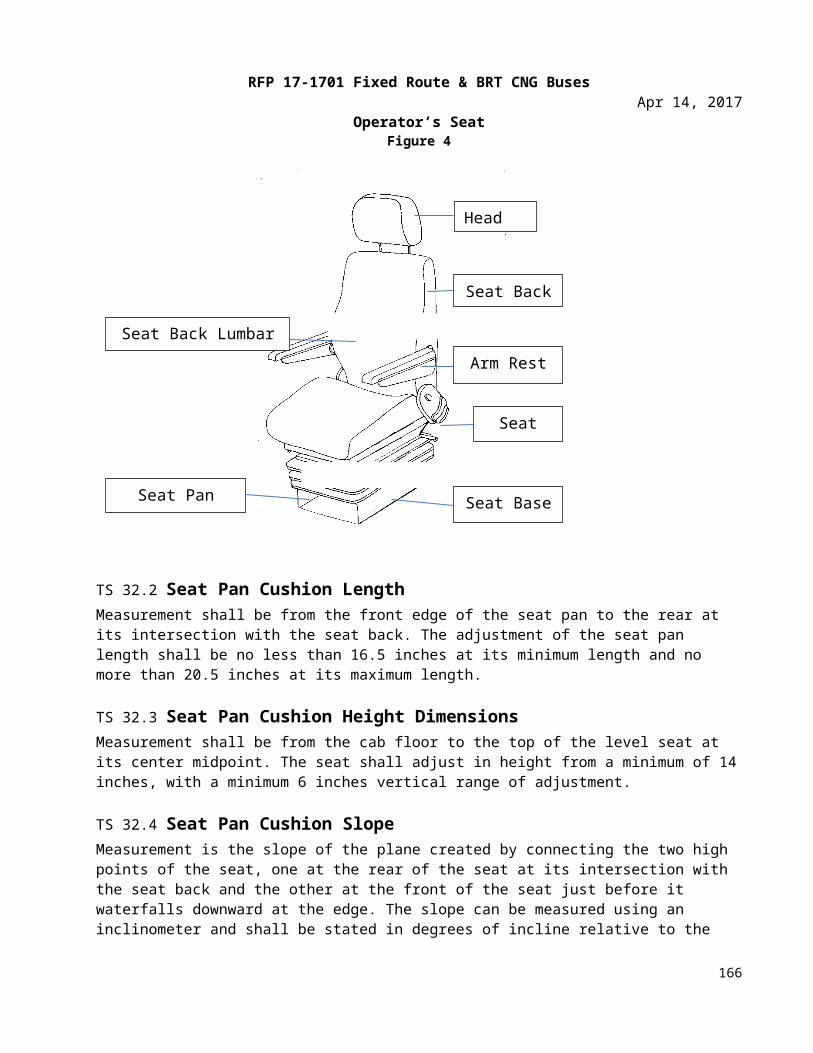
RFP 17-1701 Fixed Route & BRT CNG BusesApr 14, 2017
CER 7.4 Non-Collusion AffidavitThis affidavit is to be filled out and executed by the Proposer; if a corporation makes the bid, then by its properly executed agent. The name of the individual swearing to the affidavit should appear on the line marked “Name of Affiant.” The affiant’s capacity, when a partner or officer of a corporation, should be inserted on the line marked “Capacity.” The representative of the Proposer should sign his or her individual name at the end, not a partnership or corporation name, and swear to this affidavit before a notary public, who must attach his or her seal.
State of ____________________________________, County of _____________________________________________
I, _______________________________________________________, being first duly sworn, do hereby state that (Name of Affiant)
I am _______________________________________ of ______________________________________________________ (Capacity) (Name of Firm, Partnership or Corporation)
whose business is ___________________________________________________________________________________
and who resides at ___________________________________________________________________________________
and that _____________________________________________________________________________________________ (Give names of all persons, firms, or corporations interested in the bid)
is/are the only person(s) with me in the profits of the herein contained Contract; that the Contract is made without any connection or interest in the profits thereof with any persons making any bid or Proposal for said Work; that the said Contract is on my part, in all respects, fair and without collusion or fraud, and also that no members of the Board of Trustees, head of any department or bureau, or employee therein, or any employee of the Authority, is directly or indirectly interested therein.
______________________________________________________________________ ___________________________Signature of Affiant Date
Sworn to before me this ____________ day of __________________________, 20_____.
_______________________________________________ __________________________Notary public My commission expires Seal
166
RFP 17-1701 Fixed Route & BRT CNG BusesApr 14, 2017
CER 7.5 Lobbying CertificationThis form is to be submitted with an offer exceeding $100,000.
The Proposer certifies, to the best its knowledge and belief, that:
1. No federal appropriated funds have been paid or will be paid, by or on behalf of the undersigned, to any person for influencing or attempting to influence an officer or employee of a federal department or agency, a member of the U.S. Congress, an officer or employee of the U.S. Congress, or an employee of a member of the U.S. Congress in connection with the awarding of any federal Contract, the making of any federal grant, the making of any federal loan, the entering into of any cooperative agreement, and the extension, continuation, renewal, amendment or modification thereof.
2. If any funds other than federal appropriated funds have been paid or will be paid to any person for making lobbying contacts to an officer or employee of any agency, a member of Congress, an officer or employee of Congress, or an employee of a member of Congress in connection with this federal Contract, grant, loan or cooperative agreement, the undersigned shall complete and submit Standard Form LLL, “Disclosure Form to Report Lobbying,” in accordance with its instruction, as amended by “Government-wide Guidance for New Restrictions on Lobbying,” 61 Fed. Reg. 1413 (1/19/96).
3. The undersigned shall require that the language of this certification be included in the award documents for all sub-awards at all tiers (including subcontracts, sub-grants and contracts under grants, loans and cooperative agreements) and that all sub-recipients shall certify and disclose accordingly. This certification is a material representation of fact upon which reliance was placed when this transaction was made or entered into. Submission of this certification is a prerequisite for making or entering into this transaction imposed by 31, USC § 1352 (as amended by the Lobbying Disclosure Act of 1995). Any person who fails to file the required certification shall be subject to a civil penalty of not less than $10,000 and not more than $100,000 for each such failure.
THE PROPOSER, _____________________________________________, CERTIFIES OR AFFIRMS THE TRUTHFULNESS AND ACCURACY OF EACH STATEMENT OF ITS CERTIFICATION AND DISCLOSURE, IF ANY. IN ADDITION, THE PROPOSER UNDERSTANDS AND AGREES THAT THE PROVISIONS OF 31 USC §§ 3801 ET SEQ. APPLY TO THIS CERTIFICATION AND DISCLOSURE, IF ANY.
Name of the bidder or Proposer’s authorized official: __________________________________________________
Title: _________________________________________________________________________________________________
________________________________________________________________________ ________________________Signature Date
Per paragraph 2 of the included form Lobbying Certification, add Standard Form–LLL, “Disclosure Form to Report Lobbying,” if applicable.
167
RFP 17-1701 Fixed Route & BRT CNG BusesApr 14, 2017
CER 7.6 Certificate of Compliance with Bus Testing RequirementThe undersigned certifies that the vehicle offered in this procurement complies and will, when delivered, comply with 49 USC § 5323(c) and FTA’s implementing regulation at 49 CFR Part 665 according to the indicated one of the following three alternatives.
Mark one and only one of the three blank spaces with an “X.”
1. _____ The buses offered herewith have been tested in accordance with 49 CFR Part 665 on _____________ (date). If multiple buses are being proposed, provide additional bus testing information below or on attached sheet. The vehicles being sold should have the identical configuration and major components as the vehicle in the test report, which must be submitted with this Proposal. If the configuration or components are not identical, then the manufacturer shall provide with its Proposal a description of the change and the manufacturer’s basis for concluding that it is not a major change requiring additional testing. If multiple buses are being proposed, testing data on additional buses shall be listed on the bottom of this page.
2. _____ The manufacturer represents that the vehicle is “grandfathered” (has been used in mass transit service in the United States before October 1, 1988, and is currently being produced without a major change in configuration or components), and submits with this Proposal the name and address of the recipient of such a vehicle and the details of that vehicle’s configuration and major components.
3. _____ The vehicle is a new model and will be tested and the results will be submitted to Tulsa Transit prior to acceptance of the first bus.
The undersigned understands that misrepresenting the testing status of a vehicle acquired with federal financial assistance may subject the undersigned to civil penalties as outlined in the Department of Transportation’s regulation on Program Fraud Civil Remedies, 49 CFR Part 31. In addition, the undersigned understands that FTA may suspend or debar a manufacturer under the procedures in 49 CFR Part 29.
Company name: Name and title of the Proposer’s authorized official:
________________________________________________________________________ _______________________Authorized signature Date
168
RFP 17-1701 Fixed Route & BRT CNG BusesApr 14, 2017
CER 7.7 DBE Approval CertificationI hereby certify that the Proposer has complied with the requirements of 49 CFR 26, Participation by Disadvantaged Business Enterprises in DOT Programs, and that its goals have not been disapproved by the Federal Transit Administration.
Name and title of the Proposer’s authorized official:
________________________________________________________________________ _______________________Authorized signature Date
169
RFP 17-1701 Fixed Route & BRT CNG BusesApr 14, 2017
CER 7.8 Federal Motor Vehicle Safety StandardsThe Proposer and (if selected) Contractor shall submit (1) manufacturer’s FMVSS self-certification sticker information that the vehicle complies with relevant FMVSS or (2) manufacturer’s certified statement that the contracted buses will not be subject to FMVSS regulations.
Company name: Name of signer: Title:
________________________________________________________________________ _______________________Authorized signature Date
170
RFP 17-1701 Fixed Route & BRT CNG BusesApr 14, 2017
CER 8. Other CertificationsCER 8.1 Proposal Form
NOTE: The following is an example of a Proposal form to be modified as appropriate by Tulsa Transit and included in the RFP.
Proposer shall complete the following form and include it in the price Proposal.
PROPOSALBy execution below by a duly authorized representative(s) of the Proposer, the Proposer hereby offers to furnish equipment and services as specified in its Proposal submitted to Tulsa Transit in response to Request for Proposal No. RFP 17-1701 Fixed Route & BRT CNG Buses in its entirety.
Proposer: ______________________________________________________________________________________________
Street address: _________________________________________________________________________________________
City, state, ZIP: _________________________________________________________________________________________
Name and title of Authorized Signer(s): __________________________________________________________________
Name and title of Authorized Signer(s): __________________________________________________________________
Phone: _________________________________________________________________________________________________
______________________________________________________________________________ _____________________Authorized signature Date
______________________________________________________________________________ _____________________Authorized signature Date
171
RFP 17-1701 Fixed Route & BRT CNG BusesApr 14, 2017
CER 8.2 Notice of Award
NOTE: This form is included as an example. Standard industry practice is to execute a separate Contract as provided as an example in Appendix E.
By execution below, Tulsa Transit accepts Proposal as indicated above.
Contracting officer: _________________________________________________________________________________
________________________________________________________________________ _______________________Authorized signature Date
172
RFP 17-1701 Fixed Route & BRT CNG BusesApr 14, 2017
CER 9. Vehicle Questionnaire This form must be completed and included in the Technical Proposal.
Contractor will attach to this form:
1. A listing of current clients, including references with contact information including:
a. Nameb. Addressc. Telephone Numberd. Emaile. Type and Quantities of Buses purchased in the last 3 years.
2. A listing of staff that will be assigned to the contract (sales, customer service, technical assistance), along with information demonstrating their experience and capabilities.
3. The address of the manufacturing facilities where the buses will be constructed.
4. The technical sheets below fore each size/model bus proposed.
GENERAL COACH DATA SHEET:
[INSERT BUS TYPE]
Bus Manufacturer: __________________________________________________________________________________
Bus Model Number: ________________________________________________________________________________
Basic Body Construction Type: ____________________________________________________________________
General Dimensions
Overall length Over bumpers feet inches
Over body feet inches
Overall width Over body excluding mirrors and lights feet inches
Over body including mirrors feet inches
Over tires feet inches
Overall height (maximum) feet inches
Angle of approach Degrees
Angle of departure Degrees
Breakover angle 1 Degrees
Breakover angle 2 Degrees
Doorway clear opening (at widest point) Inches
173
RFP 17-1701 Fixed Route & BRT CNG BusesApr 14, 2017
Width with grab handles Width without grab handles Height
Front door inches Inches inches
Center door (1) inches Inches inches
Center door (2) inches Inches inches
Rear door inches Inches inches
Front axle floor height above ground (centerline of bus) inches
Center axle floor height above ground (centerline of bus) inches
Rear axle floor height above ground (centerline of bus) inches
Step height from ground (measured at center of doorway) inches
Front doorway Center doorway Ramp angle Rear doorway
Kneeled inches (a) inches (a) degrees (R1) inches (a)
Unkneeled inches (b) inches (b) degrees (R2) inches (b)
Interior head room (floor to ceiling at center of aisle)
First axle location Inches
Center of articulation Inches
Rear axle location Inches
Rear settee (in front of seat) Inches
Aisle width
Minimum width on floor between first axle wheel housings inches
Minimum width on floor between center axle (1) wheel housings inches
Minimum width on floor between center axle (2) wheel housings inches
Minimum width on floor between rear axle wheel housings inches
Minimum ground clearance
174
RFP 17-1701 Fixed Route & BRT CNG BusesApr 14, 2017
Outside axles zones Inches
Inside axles zones Inches
Horizontal turning envelope (see diagram below)
Outside body turning radius, TR0 (including bumper) feet inches
Inside Body Turning Radius innermost point, TR4 (including bumper) feet inches
Wheel base
First axle to center/rear axle Inches
Center axle to rear axle Inches
Overhang, centerline of axle over bumper
Front Inches
Rear Inches
Floor
Maximum interior floor slope (from horizontal) Degrees
Capacity
Total number of passenger sittings
Passenger seating manufacturer/model number
Total number of standing passengers (1 per 1.5 sq. ft.)
Minimum hip to knee space inches
Maximum hip to knee space inches
Restraint system type and model number
Bus weight
Curb weight Curb weight plus seated load* GVWR
175
RFP 17-1701 Fixed Route & BRT CNG BusesApr 14, 2017
First axle lbs. lbs. lbs.
Center axle lbs. lbs. lbs.
Rear axle lbs. lbs. lbs.
Total lbs. lbs. lbs.
* Including operator and passengers at 150 lbs. per person
Steering AxlesManufacturer
Type and weight rating
Model number
Drive axle (□ Center □ Rear)
Manufacturer
Type and weight rating
Model number
Drive axle ratio
Differential ratio
Hub reduction ratio (if used)
Final axle ratio (if hub reduction is used)
Brake systemMake/type of fundamental system
First axle brake chamber model
Center axle brake chamber model
Rear axle brake chamber model
First axle slack adjusterManufacturer
Model number
Center axle slack adjusterManufacturer
Model number
Rear axle slack adjusterManufacturer
Model number
First axle brake drum/rotor
176
RFP 17-1701 Fixed Route & BRT CNG BusesApr 14, 2017
Manufacturer
Center axle brake drum/rotorManufacturer
Rear axle brake drum/rotorManufacturer
Air compressor
Manufacturer
Type
Model number
Rated capacity Cfm
Capacity at idle Cfm
Maximum warranted speed Rpm
Idle speed Rpm
Drive type
Governor cut-in pressure Psi
Governor cut-out pressure Psi
Air Reservoir Capacity
Manufacturer
Supply reservoir number and size / cubic inches total
Primary reservoir number and size / cubic inches total
Secondary reservoir number and size / cubic inches total
Parking reservoir number and size / cubic inches total
Accessory reservoir number and size / cubic inches total
Other reservoir number and size / cubic inches total
Cooling SystemRadiator Charge air cooler
Manufacturer
Type
Model number
Number of tubes
Fins per inch
Fin thickness (inches)
Fin construction
177
RFP 17-1701 Fixed Route & BRT CNG BusesApr 14, 2017
Total cooling system capacity (gallons) Gallons
Radiator fan manufacturer
Fan speed/control type (mech/elect/hyb)
Surge tank capacity Gallons
Surge tank material
Overheat alarm temperature degrees F
Shutdown temperature settings degrees F
ElectricalPrimary interior lighting system
Manufacturer
Type
Model number
Alternator
Manufacturer
Type
Model number
Output at idle Amps
Voltage regulator
Manufacturer
Model number
Voltage equalizer
Manufacturer
Model number
Auxiliary inverter (120/240)
Manufacturer
Model number
Inverter technology
Output voltage(s)
Starter motor
Manufacturer
Voltage
178
RFP 17-1701 Fixed Route & BRT CNG BusesApr 14, 2017
Model number
Energy storage
Batteries – low voltage
Manufacturer
Type
Model number
Cold cranking amps
Batteries/energy storage – high voltage
Manufacturer
Type
Model number
Energy density
Specific power
Operating temperature range
Cooling/heating system
EngineManufacturer
Model number/version
Horsepower/torque rating
Fire Suppression/Methane Detection SystemManufacturer
Model number
Number of detectors fire Methane
Type of detector □ Thermal □ Optical
Battery backup □ Yes □ No
BumpersManufacturer
Type
Fuel and Exhaust System
179
RFP 17-1701 Fixed Route & BRT CNG BusesApr 14, 2017
Fuel type
Operating range and route profile
Fuel tanks (liquid fuels)
Manufacturer
Capacity (total and usable) Gallons / Gallons
Construction material
Quantity and location of tanks
Fuel tanks (gaseous fuels)
Manufacturer
Capacity (total and usable) SCF / SCF
Construction material
Quantity and location of tanks
Exhaust system
Diesel particulate filter manufacturer
Describe DPF electronic interface
Muffler manufacturer (if applicable)
Air SuspensionFront Middle Rear
Air spring manufacturer
Air spring quantity per axle
Shock absorber manufacturer
Shock absorber quantity per axle
SteeringPump manufacturer
Pump model number
Steering gear manufacturer
Steering gear model number
Steering gear type
Steering wheel diameter inches
Maximum effort at steering wheel** Unloaded stationary coach on dry asphalt pavement
180
RFP 17-1701 Fixed Route & BRT CNG BusesApr 14, 2017
HybridManufacturer
Type
Model number
Type ventilation/cooling
□ Transmission
Manufacturer
Type
Model number
Number of forward speeds
Traction motor horsepower rating
Type ventilation/cooling
PropshaftManufacturer
WheelsManufacturer
Type
Size
Mounting type
Bolt circle diameter
Protective coating
Tires
Manufacturer
Type
Size
Load range/air pressure
Door SystemDoor panels Manufacturer Type
Front door
Center door (1)
Center door (2)
Rear door
181
RFP 17-1701 Fixed Route & BRT CNG BusesApr 14, 2017
Heating and Ventilating EquipmentHeating system capacity Btu
Air conditioning system capacity Btu
Ventilating capacity CFM per passenger
Manufacturer and model
Refrigerant type
Driving heater
Manufacturer
Type
Model number
Capacity
Auxiliary heater
Manufacturer
Type
Model number
Capacity
Floor heaters
Manufacturer
Type/number
Model number
Capacity
182
RFP 17-1701 Fixed Route & BRT CNG BusesApr 14, 2017
Passenger Loading SystemManufacturer
Type (hydraulic, electric or both)
Model number
Capacity (lbs.)
Dimensions
Width of ramp inches
Length of ramp inches
Cycle times Normal idle Fast idle
Stowed to ground seconds seconds
Ground to stow seconds seconds
ElectronicsVideo system manufacturer
Video system model number
Number of cameras
Multiplex system manufacturer
Multiplex system model number
Automatic passenger counter system manufacturer
Automatic passenger counter system model number
Destination sign manufacturer
Destination sign model number
AVL/AVM system manufacturer
AVL/AVM system model number
Passenger information system manufacturer
Passenger information system model number
183
RFP 17-1701 Fixed Route & BRT CNG BusesApr 14, 2017
Coach Body FittingsPassenger windows manufacturer
Exterior/interior mirrors
Size
Manufacturer
Model number
Manufacturer part numbers
Bicycle racks
Manufacturer
Model number
Paint system
Manufacturer
Type
Operator control layout diagram:
184