Embed Size (px)
Citation preview
APT Subsystem
Chapter 5
This chapter is designed to provide the student with theknowledge of BSC APT subsystems.
OBJECTIVES:Upon completion of this chapter the student will be able to:
• name the subsystems in APT-210 09
• name the most important block groups in the subsystems
• understand diagrams describing block interaction
CME 20/CMS 40 BSC Operation & Maintenance
EN/LZT 123 3330 R1B
aa nn kkllBB
iioonnaall llyy
ttnneettnnII
5 APT Subsystem
EN/LZT 123 3330 R1B – i –
5 APT Subsystem
Table of Contents
Topic Page
GENERAL..........................................................................................167
RADIO CONTROL SUBSYSTEM (RCS)...........................................168
BG-CELL.....................................................................................................................168
BG-TRH ......................................................................................................................168
BG-CPR......................................................................................................................169
BG-RCQS ...................................................................................................................169
RADIO OPERATION & MAINTENANCE SUBSYSTEM (ROS) ........170
BG-BSSAP..................................................................................................................170
BG-ABIS .....................................................................................................................171
BG-RECTRA...............................................................................................................171
BG-SUPP....................................................................................................................172
BG-TRANSM ..............................................................................................................172
BG-TRXT ....................................................................................................................173
TRANSCEIVER ADMINISTRATION SUBSYSTEM (TAS)................173
TAS-C FUNCTIONS .......................................................Error! Bookmark not defined.
LINK HANDLING SUBSYSTEM (LHS) .............................................173
STATISTIC AND TRAFFIC MEASUREMENT SUBSYSTEM ...........174
STS FUNCTIONS.......................................................................................................175
DATA FLOW IN STS ..................................................................................................176
MEASUREMENT DATABASE....................................................................................177
MEASUREMENT REPORT GENERATOR ................................................................189
MEASUREMENT REPORT FILE OUTPUT, STANDARD FORMAT .........................191
MEASUREMENT REPORT TIMETABLE...................................................................192
OPERATIONAL INSTRUCTIONS ..............................................................................193
GUIDELINE.................................................................................................................195
CME 20/CMS 40 BSC Operation & Maintenance
– ii – EN/LZT 123 3330 R1B
BASIC INTERNAL CALL HANDLING...............................................202
PAGING......................................................................................................................203
IMMEDIATE ASSIGNMENT .......................................................................................203
ASSIGNMENT ............................................................................................................205
HANDOVER ON A DEDICATED SIGNALING CHANNEL.........................................215
CLEAR OF A TRAFFIC CHANNEL ............................................................................215
CLEAR OF A DEDICATED SIGNALING CHANNEL..................................................216
5 APT Subsystem
EN/LZT 123 3330 R1B – 167 –
GENERAL
This module describes the source system APT 210 09 which isused in BSC. APT is divided into subsystems in accordance withthe AXE 10 hierarchical structure and handles traffic andassociated operation and maintenance functions. Eachsubsystem is divided into a number of function blocks with eachblock consisting of a number of function units, hardware orsoftware. Subsystem grouping has taken into account the desireto minimize the number of subsystems affected by existing andfuture functional requirements. Systems in service can bereconfigured to accommodate new requirements by adding ormodifying blocks in the various subsystems without reallocatingloaded blocks. Each block can be replaced in an exchange whilethe switch continues processing.
APT hardware handles simple routine functions whereas themore complex functions are dealt with by the software. Softwareis stored and executed in the control system APZ. This appliesto regional, support, and central software. Regional softwareperforms routine, high-capacity requirement functions (handledby the Regional Processor Subsystem (RPS) in APZ). Centralsoftware performs complex executive functions of the lowerfrequency (handled by the Central Processor Subsystem (CPS)in APZ). Support software performs input and output of data andprograms (handled by the Support Processor Subsystem (SPS)in APZ).
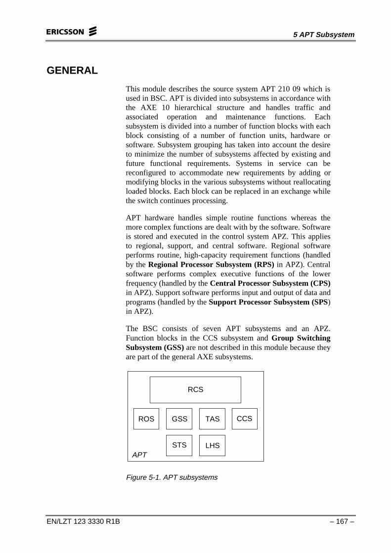
The BSC consists of seven APT subsystems and an APZ.Function blocks in the CCS subsystem and Group SwitchingSubsystem (GSS) are not described in this module because theyare part of the general AXE subsystems.
RCS
STS
ROS GSS TAS
APT
CCS
LHS
Figure 5-1. APT subsystems
CME 20/CMS 40 BSC Operation & Maintenance
– 168 – EN/LZT 123 3330 R1B
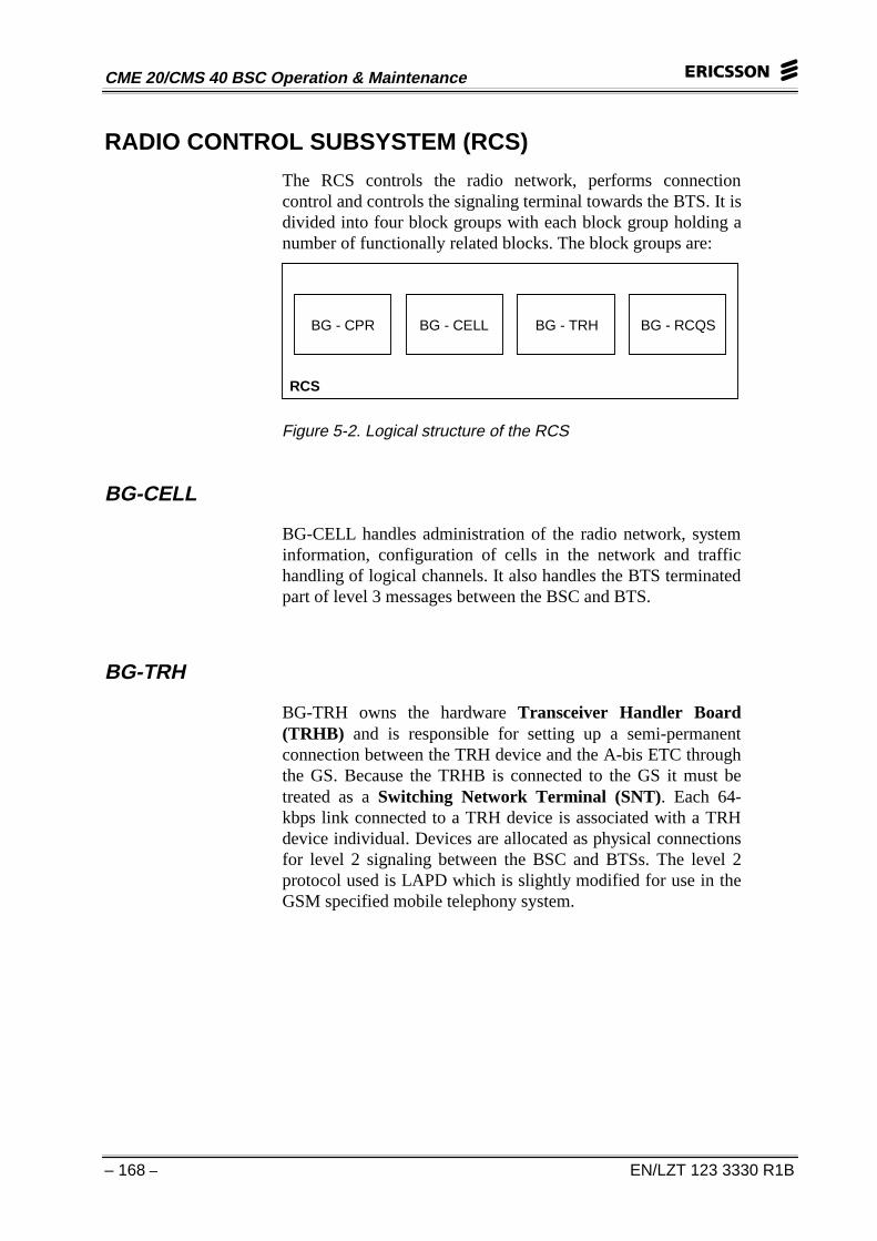
RADIO CONTROL SUBSYSTEM (RCS)
The RCS controls the radio network, performs connectioncontrol and controls the signaling terminal towards the BTS. It isdivided into four block groups with each block group holding anumber of functionally related blocks. The block groups are:
RCS
BG - CPR BG - CELL BG - TRH BG - RCQS
Figure 5-2. Logical structure of the RCS
BG-CELL
BG-CELL handles administration of the radio network, systeminformation, configuration of cells in the network and traffichandling of logical channels. It also handles the BTS terminatedpart of level 3 messages between the BSC and BTS.
BG-TRH
BG-TRH owns the hardware Transceiver Handler Board(TRHB) and is responsible for setting up a semi-permanentconnection between the TRH device and the A-bis ETC throughthe GS. Because the TRHB is connected to the GS it must betreated as a Switching Network Terminal (SNT). Each 64-kbps link connected to a TRH device is associated with a TRHdevice individual. Devices are allocated as physical connectionsfor level 2 signaling between the BSC and BTSs. The level 2protocol used is LAPD which is slightly modified for use in theGSM specified mobile telephony system.
5 APT Subsystem
EN/LZT 123 3330 R1B – 169 –
BG-TRH handles multiplexing of level 3 messages towards theBTS or MS and level 3 message distribution from the BTS orMS. Messages received on a logical channel containing themessage element “Channel Number” are forwarded to BG-CELL. Some counters for the Traffic and Event Measurementfunction in the RCS are implemented in BG-TRH. All otherblocks in BG-TRH consist of CP software only. The RPsoftware units are located in the type of regional processorcalled Regional Processor type Device (RPD). The RP unitsare further structured below the unit level into processes andmodules.
BG-CPR
All blocks in BG-CPR consist of CP software only. BG-CPRowns the connections (both signaling and traffic) between theMS, BSC, and MSC. Within these blocks most of the GSMsignaling towards the MS and MSC is handled according toGSM recommendations 04.08, 08.08 and 08.58 respectively.The block group also handles the speech and data connections aswell as data for established signaling and traffic connections.The events in the function Traffic and Event Measurement in theRadio Network appear mainly in BG-CPR.
BG-RCQS
BG-RCQS performs radio connection quality supervision on thelogical channels and contains functions for spotting undefinedneighboring cells. BG-RCQS consists of a data storing blockand a number of command receiving blocks for RCQS specificcell and BSC data. Some of the counters for Traffic andMeasurement are also implemented.
CME 20/CMS 40 BSC Operation & Maintenance
– 170 – EN/LZT 123 3330 R1B
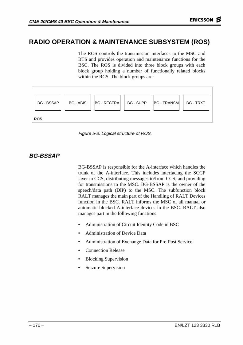
RADIO OPERATION & MAINTENANCE SUBSYSTEM (ROS)
The ROS controls the transmission interfaces to the MSC andBTS and provides operation and maintenance functions for theBSC. The ROS is divided into three block groups with eachblock group holding a number of functionally related blockswithin the RCS. The block groups are:
ROS
BG - BSSAP BG - ABIS BG - RECTRA BG - SUPP BG - TRANSM BG - TRXT
Figure 5-3. Logical structure of ROS.
BG-BSSAP
BG-BSSAP is responsible for the A-interface which handles thetrunk of the A-interface. This includes interfacing the SCCPlayer in CCS, distributing messages to/from CCS, and providingfor transmissions to the MSC. BG-BSSAP is the owner of thespeech/data path (DIP) to the MSC. The subfunction blockRALT manages the main part of the Handling of RALT Devicesfunction in the BSC. RALT informs the MSC of all manual orautomatic blocked A-interface devices in the BSC. RALT alsomanages part in the following functions:
• Administration of Circuit Identity Code in BSC
• Administration of Device Data
• Administration of Exchange Data for Pre-Post Service
• Connection Release
• Blocking Supervision
• Seizure Supervision
5 APT Subsystem
EN/LZT 123 3330 R1B – 171 –
The subfunction block ET handles the main parts of the EM/CMHandling in SNT Owning Blocks and Maintenance of SwitchingNetwork Terminal functions. It also plays an important part inthe administration of SNT in BSC and fault and qualitysupervision of the DIP functions. ET owns the ETCs (HW).
The subfunction block DIPST handles the main part of the faultsupervision, quality supervision and administration of DIPfunctions. RABDI handles the main part of the BSSAP MessageDistribution function and also plays an important part in theAdministration of Destination Point Code and NetworkIndicator functions.
BG-ABIS
BG-ABIS is responsible for the A-bis interface which handlestrunks of the A-bis interface. BG-ABIS owns the speech/datapath (DIP) to the BTS. The subfunction block RBLT handles themain part of the Handling of RBLT Devices function in the BSCand also plays an important part in the Administration of DeviceData and Administration of Exchange Data for Pre-Post Servicefunctions. Trunk devices are provided for signaling connectionsto the TRUs (LAPD connections) and for speech/dataconnections (for subscribers).
The subfunction block ET handles the main part of the EM/CMHandling in SNT Owning Blocks and Maintenance of SwitchingNetwork Terminal functions. ET also plays an important part inthe Administration of SNT in BSC, Fault Supervision of theDIP, and Quality Supervision of DIP functions. ET owns theETCs (HW). DIPST handles the main parts of fault supervision,quality supervision and adminstration of DIP functions.
BG-RECTRA
BG-RECTRA handles recording and tracing functions for theBSC.
CME 20/CMS 40 BSC Operation & Maintenance
– 172 – EN/LZT 123 3330 R1B
BG-SUPP
BG-SUPP provides support and service to the differentsubsystems in the BSC. These functions include:
• Processor and Exchange Input Load Measurement
• Load Control
• Exchange Input Load Observation
• Exchange Input Load Supervision
• Processor Load Observation
• Reading of Processor
• Exchange Input Load
• Handling command access for cell and radio network dataand BSC Unique Function Codes
• Translation Functions
• Semipermanent Connections
• Time Table
BG-TRANSM
BG-TRANSM handles commands for SNT, DIP, and devicefunctions for the BSC. These functions include:
• DIP Administration
• DIP Fault Supervision
• DIP Quality Supervision
• Exchange Data for Pre-Post Service Administration
• Manual Blocking and Deblocking of Devices
• Blocking Supervision of Devices
• Reading of Device State Information
• Circuit Identity Code in BSC Administration
• Administration of Destination Point Code and NetworkIndicator in BSC
• Device Data Administration
• Access Function
• Command access for exchange data
5 APT Subsystem
EN/LZT 123 3330 R1B – 173 –
• SNT Administration
• Switching Network Terminal Maintenance
BG-TRXT
BG-TRXT handles the main parts of the TRXT function,Common Administration and Maintenance. This includes:
• Supervision of Transceivers
• Administration and Supervision for Periodic Tests andAutomatic Supervision
• Common Administration and Maintenance
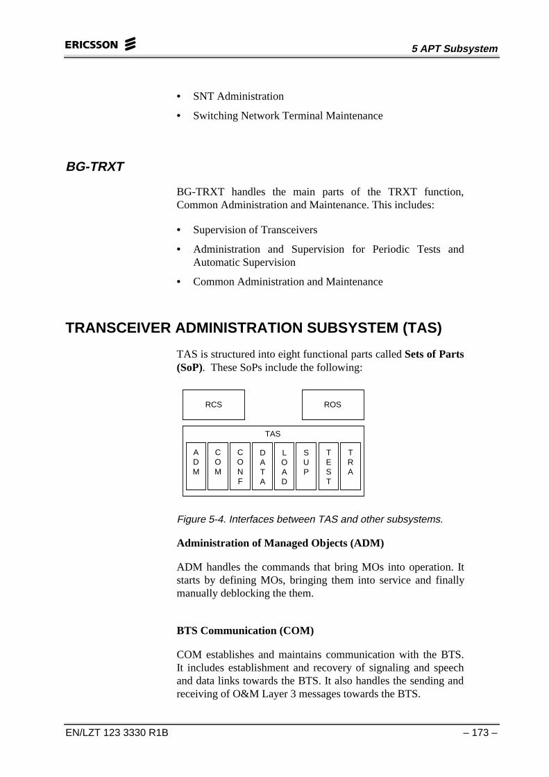
TRANSCEIVER ADMINISTRATION SUBSYSTEM (TAS)
TAS is structured into eight functional parts called Sets of Parts(SoP). These SoPs include the following:
RCS ROS
TAS
ADM
COM
CONF
DATA
LOAD
SUP
TEST
TRA
Figure 5-4. Interfaces between TAS and other subsystems.
Administration of Managed Objects (ADM)
ADM handles the commands that bring MOs into operation. Itstarts by defining MOs, bringing them into service and finallymanually deblocking the them.
BTS Communication (COM)
COM establishes and maintains communication with the BTS.It includes establishment and recovery of signaling and speechand data links towards the BTS. It also handles the sending andreceiving of O&M Layer 3 messages towards the BTS.
CME 20/CMS 40 BSC Operation & Maintenance
– 174 – EN/LZT 123 3330 R1B
Configuration (CONF)
CONF matches the configuration requirements provided by RCSto the available equipment and then maintains and updates thisconfiguration based on configuration requirement changesand/or equipment status changes.
Data and Structure Handling (DATA)
DATA is the central part of TAS. It acts as a coordinator withinthe susbsystem. It handles priorities between different activitiesand controls the different dependencies between MOs. Inaddition, it coordinates start/restart and recovery of MOs. Alldata concerning MOs is stored and maintained by one MO dataowner per MO type.
BTS Loading (LOAD)
LOAD performs the loading of software packages from the BSCto the BTS. It handles the upload of software from the I/Osystem in the BSC and performs software file transfer to theBTS. It also performs reset and restart of MOs.
Supervision and Alarm Handling (SUP)
SUP supervises the status of the BTS by acting on BTS relatedfaults and the various link and device faults. It also coordinatesgeneration of and stopping of BTS equipment alarms and BTSexternal alarms.
Test and Verification (TEST)
TEST performs manual or automatic tests of MOs. During therecovery process, TEST verifies the status of the BTS. It alsohandles various status and fault information printouts.
Transcoder Handling (TRA)
TRA handles the operation and maintenance of the transcoderhardware. This consists of an SNT and device owner blocks plustwo separate blocks for transcoder specific alarm handling andcommands for manipulating transcoder data.
5 APT Subsystem
EN/LZT 123 3330 R1B – 175 –
LINK HANDLING SUBSYSTEM (LHS)
LHS handles the connections between the BSC and the BTS.The hardware for LHS is located at the BTS site. It operates asone or more radio selectors, each controlled by an EMRP whichis connected to the CP via a STR-STC signaling link.
The PCM links from the BSC terminates at the ETC boards inLHS and the physical connections from the BTS terminates inRadio Transceiver Terminals (RTT). Up to 10 ETBs andRTTs can be connected to one radio selector. Each radio selectorincludes a Time Switch (TSW) which works as a Digital CrossConnect (DCC) with semiperminanent connections. Thus thedifferent 64 kbit/s connections on the PCM links from the BSCto the transceivers can be reconfigured by means of the TSW.
The radio interface line terminals, Signaling TerminalRegional (STR), Extension Module Regional Processor(EMRP) together with the radio selectors, make up theTransmission Radio Interface (TRI). Each TRI can handleone I/O terminal and up to 32 external alarms. The terminal canbe used for operations and maintenance functions within theBSS. The TRI is implemented in central and regional softwareand hardware. Besides the main digital cross connector function,the TRI also contains administrative functions for configurationand maintenance. The TRI is automatically supervised and whena serious fault is detected the faulty equipment is isolated andtaken out of service.
STATISTIC AND TRAFFIC MEASUREMENT SUBSYSTEM
STS is implemented through software in the SP and designed asa box for introduction in any source system using APZ 211 orAPZ 212. It encompasses functions for live traffic observationand traffic measurements. STS functions can be specified andscheduled through the use of commands. Since the SP handlesall functions for STS, a CP-SP dialogue must be initiated beforeusing SP commands. The path building command IMLIT is usedfor that purpose.
Traffic handling blocks contain counters for the collection oftraffic events. These counters are updated concurrently with thetraffic process. They are scanned periodically by STS whichprocesses the values and compiles the results for output. Statisticand traffic measurements are tools for:
CME 20/CMS 40 BSC Operation & Maintenance
– 176 – EN/LZT 123 3330 R1B
• Network planning
• Dimensioning of entities (exchanges), routes and cells
• Providing traffic prognoses and traffic handling capability.
• Supervision and trouble shooting
STS FUNCTIONS
Measurement Data base: Administrates transfer of traffic andmeasurement counters to the database at the time specified byuser command. Collection of data is started or stopped bycommand.
Measurement Report Generator: A report program in whichthe user can specify alphanumeric reports by means ofcommands. It generates one or several reports according to agiven specification.
Measurement Report File Output, Standard Format:Produces file output reports according to a given specification.
Measurement Report Time Table: Used to schedule reports.The desired report, measurement object, and time schedule areset by command.
Measurement Object Group Handler: Provides logicalgrouping of objects.
5 APT Subsystem
EN/LZT 123 3330 R1B – 177 –
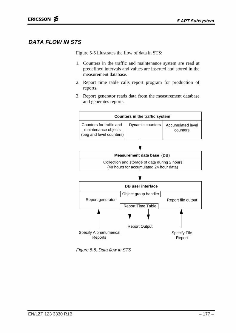
DATA FLOW IN STS
Figure 5-5 illustrates the flow of data in STS:
1. Counters in the traffic and maintenance system are read atpredefined intervals and values are inserted and stored in themeasurement database.
2. Report time table calls report program for production ofreports.
3. Report generator reads data from the measurement databaseand generates reports.
Counters in the traffic system
Counters for traffic andmaintenance objects
(peg and level counters)
Dynamic counters Accumulated levelcounters
Measurement data base (DB)
Collection and storage of data during 2 hours(48 hours for accumulated 24 hour data)
DB user interface
Report generator Report file output
Object group handler
Report Time Table
Specify AlphanumericalReports
Specify FileReport
Report Output
Figure 5-5. Data flow in STS
CME 20/CMS 40 BSC Operation & Maintenance
– 178 – EN/LZT 123 3330 R1B
MEASUREMENT DATA BASE
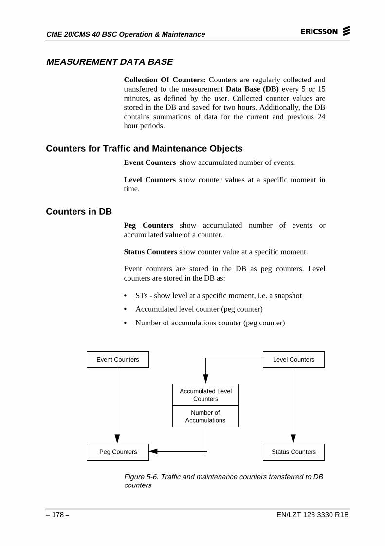
Collection Of Counters: Counters are regularly collected andtransferred to the measurement Data Base (DB) every 5 or 15minutes, as defined by the user. Collected counter values arestored in the DB and saved for two hours. Additionally, the DBcontains summations of data for the current and previous 24hour periods.
Counters for Traffic and Maintenance ObjectsEvent Counters show accumulated number of events.
Level Counters show counter values at a specific moment intime.
Counters in DBPeg Counters show accumulated number of events oraccumulated value of a counter.
Status Counters show counter value at a specific moment.
Event counters are stored in the DB as peg counters. Levelcounters are stored in the DB as:
• STs - show level at a specific moment, i.e. a snapshot
• Accumulated level counter (peg counter)
• Number of accumulations counter (peg counter)
Accumulated LevelCounters
Number ofAccumulations
Event Counters Level Counters
Peg Counters Status Counters
Figure 5-6. Traffic and maintenance counters transferred to DBcounters
5 APT Subsystem
EN/LZT 123 3330 R1B – 179 –
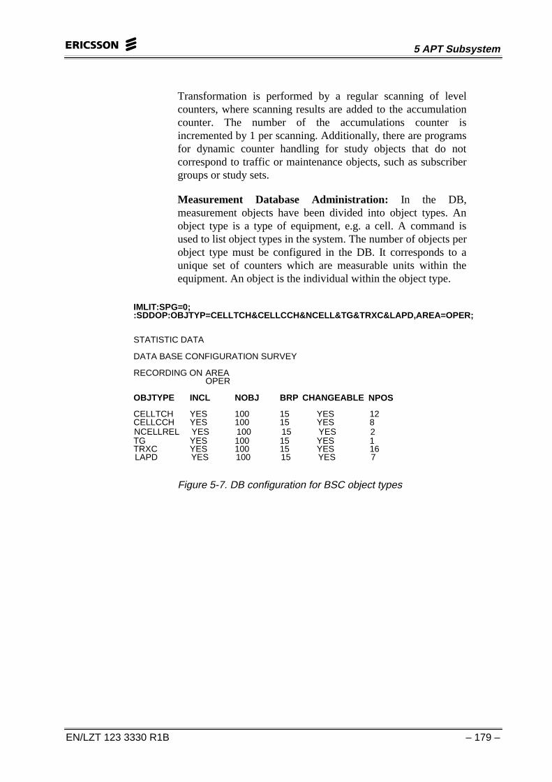
Transformation is performed by a regular scanning of levelcounters, where scanning results are added to the accumulationcounter. The number of the accumulations counter isincremented by 1 per scanning. Additionally, there are programsfor dynamic counter handling for study objects that do notcorrespond to traffic or maintenance objects, such as subscribergroups or study sets.
Measurement Database Administration: In the DB,measurement objects have been divided into object types. Anobject type is a type of equipment, e.g. a cell. A command isused to list object types in the system. The number of objects perobject type must be configured in the DB. It corresponds to aunique set of counters which are measurable units within theequipment. An object is the individual within the object type.
IMLIT:SPG=0;:SDDOP:OBJTYP=CELLTCH&CELLCCH&NCELL&TG&TRXC&LAPD,AREA=OPER;
STATISTIC DATA
DATA BASE CONFIGURATION SURVEY
RECORDING ON AREAOPER
OBJTYPE INCL NOBJ BRP CHANGEABLE NPOS
CELLTCH YES 100 15 YES 12CELLCCH YES 100 15 YES 8NCELLREL YES 100 15 YES 2TG YES 100 15 YES 1TRXC YES 100 15 YES 16LAPD YES 100 15 YES 7
Figure 5-7. DB configuration for BSC object types
CME 20/CMS 40 BSC Operation & Maintenance
– 180 – EN/LZT 123 3330 R1B
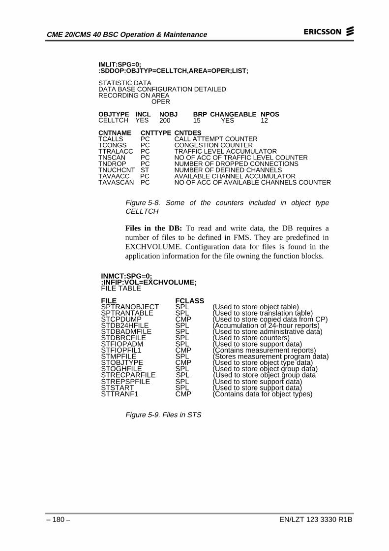
IMLIT:SPG=0;:SDDOP:OBJTYP=CELLTCH,AREA=OPER;LIST;
STATISTIC DATADATA BASE CONFIGURATION DETAILEDRECORDING ON AREA
OPER
OBJTYPE INCL NOBJ BRP CHANGEABLE NPOSCELLTCH YES 200 15 YES 12
CNTNAME CNTTYPE CNTDESTCALLS PC CALL ATTEMPT COUNTERTCONGS PC CONGESTION COUNTERTTRALACC PC TRAFFIC LEVEL ACCUMULATORTNSCAN PC NO OF ACC OF TRAFFIC LEVEL COUNTERTNDROP PC NUMBER OF DROPPED CONNECTIONSTNUCHCNT ST NUMBER OF DEFINED CHANNELSTAVAACC PC AVAILABLE CHANNEL ACCUMULATORTAVASCAN PC NO OF ACC OF AVAILABLE CHANNELS COUNTER
Figure 5-8. Some of the counters included in object typeCELLTCH
Files in the DB: To read and write data, the DB requires anumber of files to be defined in FMS. They are predefined inEXCHVOLUME. Configuration data for files is found in theapplication information for the file owning the function blocks.
INMCT:SPG=0;:INFIP:VOL=EXCHVOLUME;FILE TABLE
FILE FCLASSSPTRANOBJECT SPL (Used to store object table)SPTRANTABLE SPL (Used to store translation table)STCPDUMP CMP (Used to store copied data from CP)STDB24HFILE SPL (Accumulation of 24-hour reports)STDBADMFILE SPL (Used to store administrative data)STDBRCFILE SPL (Used to store counters)STFIOPADM SPL (Used to store support data)STFIOPFIL1 CMP (Contains measurement reports)STMPFILE SPL (Stores measurement program data)STOBJTYPE CMP (Used to store object type data)STOGHFILE SPL (Used to store object group data)STRECPARFILE SPL (Used to store object group dataSTREPSPFILE SPL (Used to store support data)STSTART SPL (Used to store support data)STTRANF1 CMP (Contains data for object types)
Figure 5-9. Files in STS
5 APT Subsystem
EN/LZT 123 3330 R1B – 181 –
Translation: The translation function is used to connectcounter(s) for an object or individual to an external name used inthe STS reports. This function provides users with the capabilityto translate one or more objects for a report containing selectedobjects. Updates of translation tables are completedautomatically every 24 hours and manually when necessary, viacommand SDDTI (Updating of translation tables).
Counters in the DB Used by the BSC For Traffic and EventMeasurements in the Radio Network:
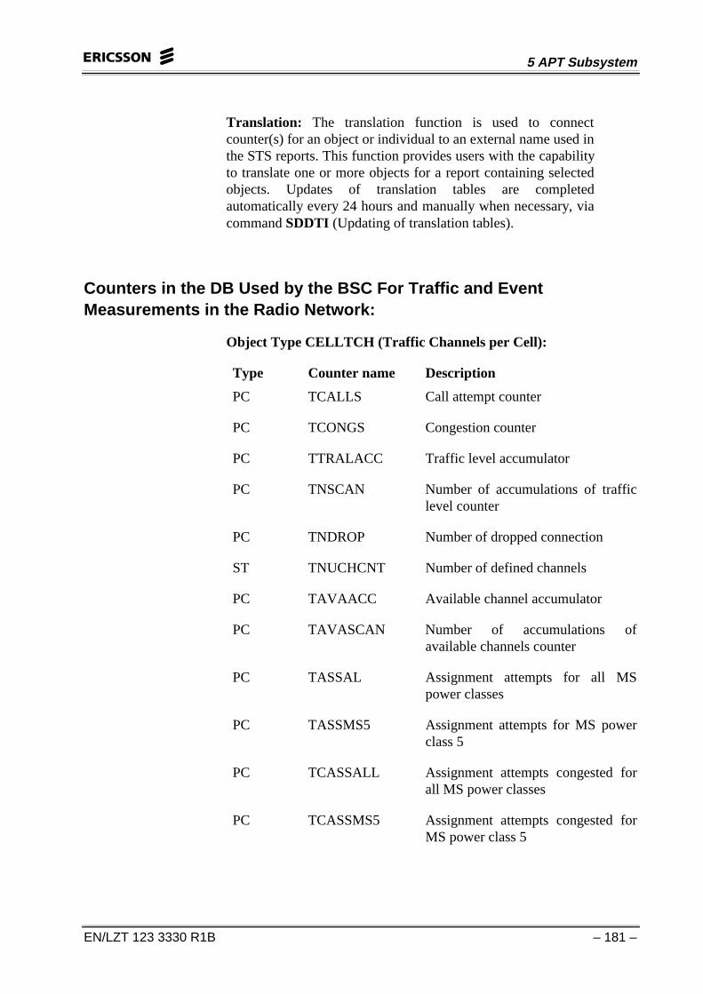
Object Type CELLTCH (Traffic Channels per Cell):
Type Counter name Description
PC TCALLS Call attempt counter
PC TCONGS Congestion counter
PC TTRALACC Traffic level accumulator
PC TNSCAN Number of accumulations of trafficlevel counter
PC TNDROP Number of dropped connection
ST TNUCHCNT Number of defined channels
PC TAVAACC Available channel accumulator
PC TAVASCAN Number of accumulations ofavailable channels counter
PC TASSAL Assignment attempts for all MSpower classes
PC TASSMS5 Assignment attempts for MS powerclass 5
PC TCASSALL Assignment attempts congested forall MS power classes
PC TCASSMS5 Assignment attempts congested forMS power class 5
CME 20/CMS 40 BSC Operation & Maintenance
– 182 – EN/LZT 123 3330 R1B
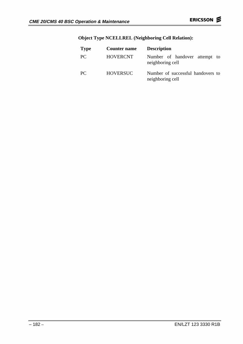
Object Type NCELLREL (Neighboring Cell Relation):
Type Counter name Description
PC HOVERCNT Number of handover attempt toneighboring cell
PC HOVERSUC Number of successful handovers toneighboring cell
5 APT Subsystem
EN/LZT 123 3330 R1B – 183 –
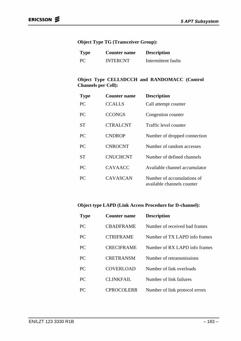
Object Type TG (Transceiver Group):
Type Counter name Description
PC INTERCNT Intermittent faults
Object Type CELLSDCCH and RANDOMACC (ControlChannels per Cell):
Type Counter name Description
PC CCALLS Call attempt counter
PC CCONGS Congestion counter
ST CTRALCNT Traffic level counter
PC CNDROP Number of dropped connection
PC CNROCNT Number of random accesses
ST CNUCHCNT Number of defined channels
PC CAVAACC Available channel accumulator
PC CAVASCAN Number of accumulations ofavailable channels counter
Object type LAPD (Link Access Procedure for D-channel):
Type Counter name Description
PC CBADFRAME Number of received bad frames
PC CTRIFRAME Number of TX LAPD info frames
PC CRECIFRAME Number of RX LAPD info frames
PC CRETRANSM Number of retransmissions
PC COVERLOAD Number of link overloads
PC CLINKFAIL Number of link failures
PC CPROCOLERR Number of link protocol errors
CME 20/CMS 40 BSC Operation & Maintenance
– 184 – EN/LZT 123 3330 R1B
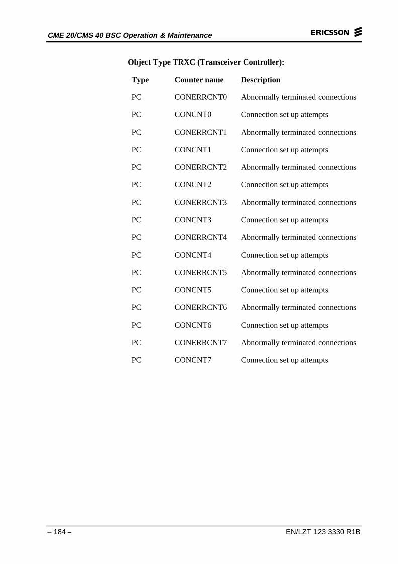
Object Type TRXC (Transceiver Controller):
Type Counter name Description
PC CONERRCNT0 Abnormally terminated connections
PC CONCNT0 Connection set up attempts
PC CONERRCNT1 Abnormally terminated connections
PC CONCNT1 Connection set up attempts
PC CONERRCNT2 Abnormally terminated connections
PC CONCNT2 Connection set up attempts
PC CONERRCNT3 Abnormally terminated connections
PC CONCNT3 Connection set up attempts
PC CONERRCNT4 Abnormally terminated connections
PC CONCNT4 Connection set up attempts
PC CONERRCNT5 Abnormally terminated connections
PC CONCNT5 Connection set up attempts
PC CONERRCNT6 Abnormally terminated connections
PC CONCNT6 Connection set up attempts
PC CONERRCNT7 Abnormally terminated connections
PC CONCNT7 Connection set up attempts
5 APT Subsystem
EN/LZT 123 3330 R1B – 185 –
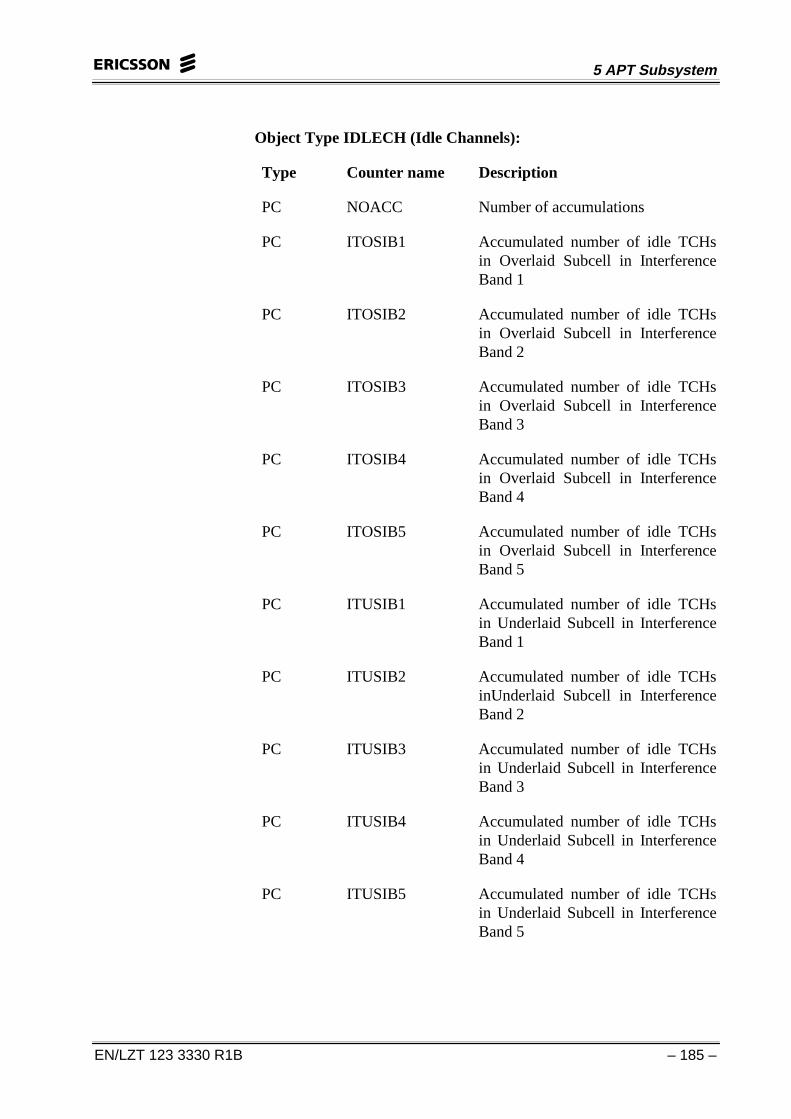
Object Type IDLECH (Idle Channels):
Type Counter name Description
PC NOACC Number of accumulations
PC ITOSIB1 Accumulated number of idle TCHsin Overlaid Subcell in InterferenceBand 1
PC ITOSIB2 Accumulated number of idle TCHsin Overlaid Subcell in InterferenceBand 2
PC ITOSIB3 Accumulated number of idle TCHsin Overlaid Subcell in InterferenceBand 3
PC ITOSIB4 Accumulated number of idle TCHsin Overlaid Subcell in InterferenceBand 4
PC ITOSIB5 Accumulated number of idle TCHsin Overlaid Subcell in InterferenceBand 5
PC ITUSIB1 Accumulated number of idle TCHsin Underlaid Subcell in InterferenceBand 1
PC ITUSIB2 Accumulated number of idle TCHsinUnderlaid Subcell in InterferenceBand 2
PC ITUSIB3 Accumulated number of idle TCHsin Underlaid Subcell in InterferenceBand 3
PC ITUSIB4 Accumulated number of idle TCHsin Underlaid Subcell in InterferenceBand 4
PC ITUSIB5 Accumulated number of idle TCHsin Underlaid Subcell in InterferenceBand 5
CME 20/CMS 40 BSC Operation & Maintenance
– 186 – EN/LZT 123 3330 R1B
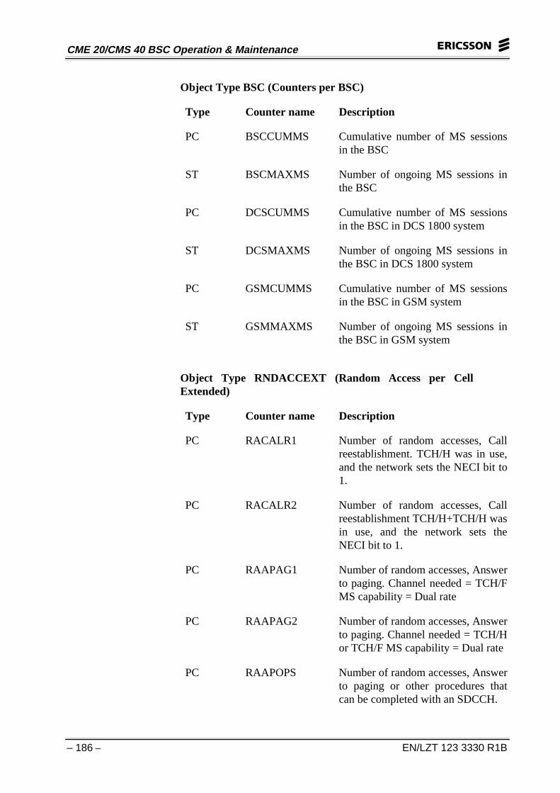
Object Type BSC (Counters per BSC)
Type Counter name Description
PC BSCCUMMS Cumulative number of MS sessionsin the BSC
ST BSCMAXMS Number of ongoing MS sessions inthe BSC
PC DCSCUMMS Cumulative number of MS sessionsin the BSC in DCS 1800 system
ST DCSMAXMS Number of ongoing MS sessions inthe BSC in DCS 1800 system
PC GSMCUMMS Cumulative number of MS sessionsin the BSC in GSM system
ST GSMMAXMS Number of ongoing MS sessions inthe BSC in GSM system
Object Type RNDACCEXT (Random Access per CellExtended)
Type Counter name Description
PC RACALR1 Number of random accesses, Callreestablishment. TCH/H was in use,and the network sets the NECI bit to1.
PC RACALR2 Number of random accesses, Callreestablishment TCH/H+TCH/H wasin use, and the network sets theNECI bit to 1.
PC RAAPAG1 Number of random accesses, Answerto paging. Channel needed = TCH/FMS capability = Dual rate
PC RAAPAG2 Number of random accesses, Answerto paging. Channel needed = TCH/Hor TCH/F MS capability = Dual rate
PC RAAPOPS Number of random accesses, Answerto paging or other procedures thatcan be completed with an SDCCH.
5 APT Subsystem
EN/LZT 123 3330 R1B – 187 –
PC RAORSPE Number of random accesses,Originating speech call from dual-rate MS when TCH/ H is sufficientand the network sets the NECI bit to1.
PC RAORDAT Number of random accesses,Originating data call from dual-rateMS when TCH/H is sufficient andthe network sets the NECI bit to 1.
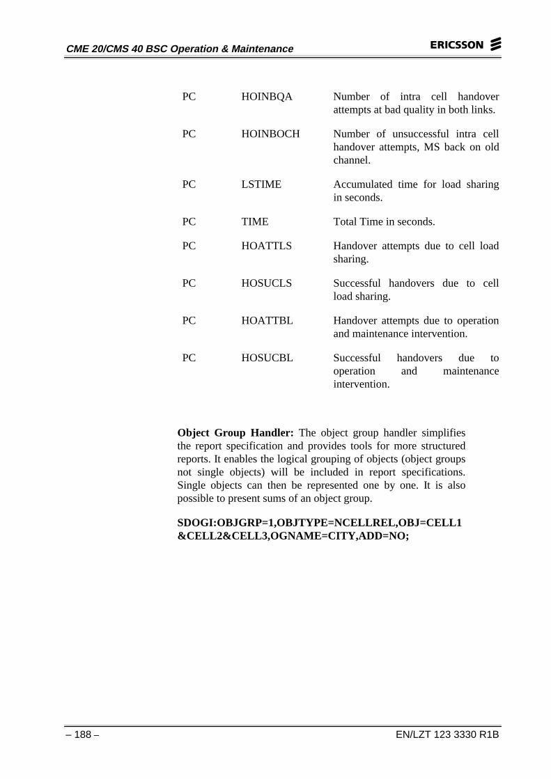
Object Type CELLEVENT (Channel Change per Cell)
Type Counter name Description
PC HOAATOL Handover attempts to overlaidsubcell.
PC HOSUCOL Number of Successful handoverattempts to overlaid subcell.
PC HOAATUL Handover attempts to underlaidsubcell.
PC HOSUCUL Number of Successful handoverattempts to underlaid subcell.
PC HOINUQA Number of intra cell handoverattempts at bad uplink quality.
PC HOINDQA Number of intra cell handoverattempts at bad downlink quality.
PC HOINSUC Number of successful intra cellhandovers.
PC DISNORM Normal disconnection
PC DISBQA Disconnection at bad radio linkquality
PC DISBSS Disconnection at bad signal strength
PC DISETA Disconnection at excessive TA
CME 20/CMS 40 BSC Operation & Maintenance
– 188 – EN/LZT 123 3330 R1B
PC HOINBQA Number of intra cell handoverattempts at bad quality in both links.
PC HOINBOCH Number of unsuccessful intra cellhandover attempts, MS back on oldchannel.
PC LSTIME Accumulated time for load sharingin seconds.
PC TIME Total Time in seconds.
PC HOATTLS Handover attempts due to cell loadsharing.
PC HOSUCLS Successful handovers due to cellload sharing.
PC HOATTBL Handover attempts due to operationand maintenance intervention.
PC HOSUCBL Successful handovers due tooperation and maintenanceintervention.
Object Group Handler: The object group handler simplifiesthe report specification and provides tools for more structuredreports. It enables the logical grouping of objects (object groupsnot single objects) will be included in report specifications.Single objects can then be represented one by one. It is alsopossible to present sums of an object group.
SDOGI:OBJGRP=1,OBJTYPE=NCELLREL,OBJ=CELL1&CELL2&CELL3,OGNAME=CITY,ADD=NO;
5 APT Subsystem
EN/LZT 123 3330 R1B – 189 –
Heading
Adminfo
Recorded data
Heading
Adminfo
Heading
Recorded data
Heading
Recorded data
Figure 5-10. Single and Combined report
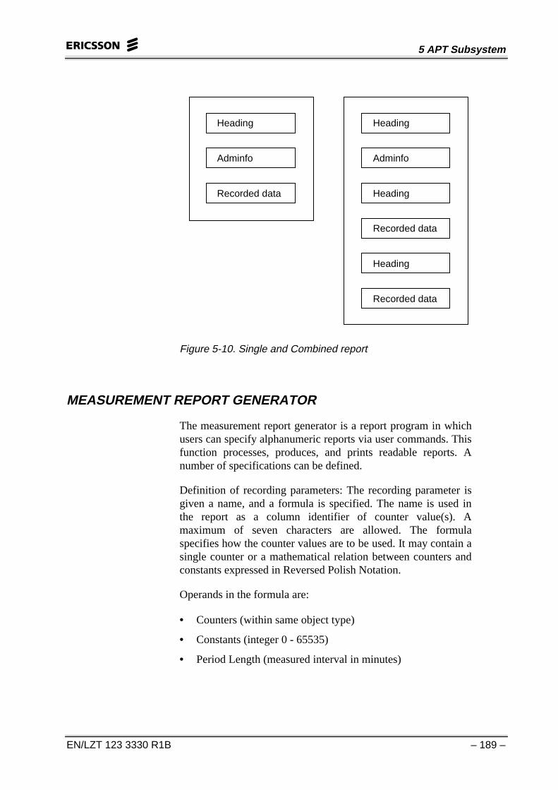
MEASUREMENT REPORT GENERATOR
The measurement report generator is a report program in whichusers can specify alphanumeric reports via user commands. Thisfunction processes, produces, and prints readable reports. Anumber of specifications can be defined.
Definition of recording parameters: The recording parameter isgiven a name, and a formula is specified. The name is used inthe report as a column identifier of counter value(s). Amaximum of seven characters are allowed. The formulaspecifies how the counter values are to be used. It may contain asingle counter or a mathematical relation between counters andconstants expressed in Reversed Polish Notation.
Operands in the formula are:
• Counters (within same object type)
• Constants (integer 0 - 65535)
• Period Length (measured interval in minutes)
CME 20/CMS 40 BSC Operation & Maintenance
– 190 – EN/LZT 123 3330 R1B
Allowed operators are:
+ for addition
- for subtraction
* for multiplication
/ for division
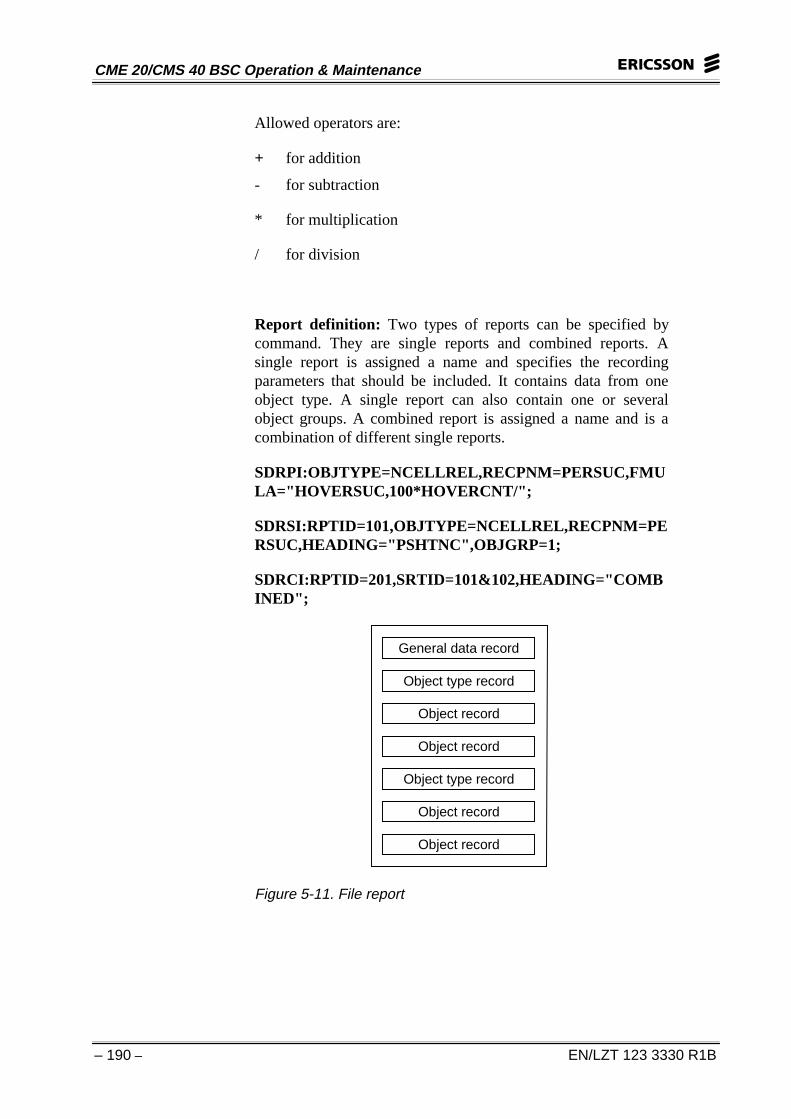
Report definition: Two types of reports can be specified bycommand. They are single reports and combined reports. Asingle report is assigned a name and specifies the recordingparameters that should be included. It contains data from oneobject type. A single report can also contain one or severalobject groups. A combined report is assigned a name and is acombination of different single reports.
SDRPI:OBJTYPE=NCELLREL,RECPNM=PERSUC,FMULA="HOVERSUC,100*HOVERCNT/";
SDRSI:RPTID=101,OBJTYPE=NCELLREL,RECPNM=PERSUC,HEADING="PSHTNC",OBJGRP=1;
SDRCI:RPTID=201,SRTID=101&102,HEADING="COMBINED";
General data record
Object type record
Object record
Object record
Object type record
Object record
Object record
Figure 5-11. File report
5 APT Subsystem
EN/LZT 123 3330 R1B – 191 –
MEASUREMENT REPORT FILE OUTPUT, STANDARD FORMAT
This function handles report file output. Data files containingreports can be transferred to a data link or magnetic tape.Transfers are managed by the File Process Utility (FPU). Datain the reports can be manually interpreted by means ofSTFIOPFILE printout description or post-processed. Everyreport specification has a separate file for outputs. These filesare divided into two types of subfiles.
Demand Report Output Subfile: There is only space for onereport output at a time in the subfile. The next demand reportprintout is stored in the same subfile. This means that after eachdemand report printout, the user must check the subfile to see ifthere is another report there.
Periodical Produced Report Output Subfile(s): This type ofsubfile contains report printouts transferred to a file by means ofa report timetable. The subfile contains a number of reportsproduced during one time interval. The subfile collectioninterval is set by command with a default value of 1 hour. Thesubfile is closed when a subfile collection interval is complete.FPU is informed when the subfile is ready for post processingafter which a new subfile is opened.
INFII:FILE=TEST,VOL=EXCHVOLUME,RLENGTH=2048,SIZE=20,EXP=20,TYPE=SEQ,FCLASS=CMP;
SDFOI:RPTID=37,FILE=TEST,OBJTYPE=NCELLREL;
SDFSC:FILE=TEST,INTM=15;
CME 20/CMS 40 BSC Operation & Maintenance
– 192 – EN/LZT 123 3330 R1B
MEASUREMENT REPORT TIMETABLE
The timetable function administrates time schedules that controlwhen measurements on specified recording objects are to bemade. This function enables the staff to order:
• periodical measurements according to intervals specified inthe time schedule
• reports immediately
Measuring Program (MP): This is used for administration ofperiodical measurements. MP is identified by a user assignednumber. Different MPs are independent of each other. SeveralMPs can be defined to run on the same time schedule andperform registration on the same objects. 256-Mbps areavailable by default.
Time Schedule: The time schedule indicates when a report is tobe printed. It also provides the collection interval thatdetermines when data collection is to be performed. The timeschedule is defined by starting date, starting time, stop time, andcollection interval.
The smallest unit in the schedule is the Basic Recording Period(BRP). That is, the collection interval must be equal to or amultiple of the BRP. The first output occurs at the starting dateand time and contains collected data from the precedingmeasurement interval. The following reports are output at thestarting date and time plus n * collection interval. Collectioncontinues until the stop date and time are reached or atermination command is entered.
SDTDP:RPTID=101,OBJTYPE=NCELLREL,INT=30;(Immediate report)
SDTPI:MP=1,RPTID=101,INT=24,TIME=1200;(Timescheduled report)
5 APT Subsystem
EN/LZT 123 3330 R1B – 193 –
OPERATIONAL INSTRUCTIONS
Statistic data, measurement database administration:
• Installation of the measurement database
• Changes in measurement database administration
• Request printout of measurement database characteristics
• Start collection of statistic data
• Stop collection of statistic data
• Update translation tables
Statistic data, report generator administration:
• Definition of single reports
• Definition of combined reports
• Removal of report specification
• Print out of report specification
• Removal of recording parameter specification
• Print out of recording parameter specification
• Change of single report specification
• Change of combined report specification
Statistic data, file output standard format, reportadministration:
• Initiate file output report specification
• Remove file output report specification
• Print file output report specification
• Change file output subfile output collection interval
• Print file output subfile output collection interval
CME 20/CMS 40 BSC Operation & Maintenance
– 194 – EN/LZT 123 3330 R1B
Statistic data, report measurement administration:
• Start of measurement
• Stop of measurement
• Print out of defined measurement
• Request of immediate measurement results
Statistic data, object group handler administration:
• Definition of an object group
• Removal of an object group
• Print out of an object group specification
• Print out of object group identities
• Change of objects in an object group
Statistic administration in BSC, traffic measurement on cells:
• Define a report for traffic measurements on cells
• Generate reports for traffic measurement on cells
• Generate file output for traffic measurement on cells
Statistic administration in BSC, handover measurement:
• Define a report for handover measurement
• Generate reports for handover measurement
• Generate file output for handover measurement
Statistic administration in BSC, dropped connectionsmeasurement:
• Define a report for dropped connections measurements
• Generate reports for dropped connections measurement
• Generate file output for dropped connections measurement
5 APT Subsystem
EN/LZT 123 3330 R1B – 195 –
Statistic administration in BSC, BTS equipment disturbances:
• Define a report for BTS equipment disturbances
• Generate reports for BTS equipment disturbances
• Generate file output for BTS equipment disturbances
Statistic administration in BSC, random access measurement:
• Define a report for random access measurement
• Generate reports for random access measurement
• Generate file output for random access measurement
Statistic administration in BSC, LAPD link measurements:
• Define a report for LAPD link measurements
• Generate reports for LAPD link measurements
• Generate file output for LAPD link measurements
GUIDELINE
Measurement Data base Administration:
Action: Start data configuration session. Initiate transfer ofinitial data to correction area.
IMLIT:SPG=0;
SDDOI;
Result: EXECUTED
Action: Request survey printout of database characteristics fromcorrection area.
SDDOP: OBJTYPE = ALL, AREA = CORR;
Result: Statistic Database Configuration Survey
Action: Define object types for measurement.
SDDOC: OBJTYPE=CELLTCH, INCL=YES,BRP=15,NOBJ=1200;
Result: EXECUTED
CME 20/CMS 40 BSC Operation & Maintenance
– 196 – EN/LZT 123 3330 R1B
Action: Terminate configuration session.
SDDOE: EXEC;
Result: ORDERED
Action: Release terminal and wait for answer printout.
Result: STATISTIC DATA MEASUREMENT DATABASECONFIGURED
Comment: Data base will be configured and data incorrection area will be switched to operating area. To leavesession without changes, use parameter QUIT.
Action: Check data defined in data base.
IMLIT:SPG=0;
SDDOP:OBJTYPE=ALL,AREA=OPER;
Result: STATISTIC DATABASE CONFIGURATIONSURVEY.
Action: Initiate collection of statistic counters.
SDDCI;
Result: EXECUTED
Comment: Statistic counters are copied from CP to SP.Collection interval is set in a data base for each object type,parameter BRP.
Object Group Handler Administration:
Action: Print all defined object group identities.
SDOIP;
Result: STATISTIC DATA OBJECT GROUPIDENTITIES
Action: Define object group and connect object.
SDOGI:OBJGRP=16,OBJTYPE=CELLTCH,OGNAME=’’TEST’’,OBJ=CELL1,ADD=NO;
Result: EXECUTED
Comment: If all objects in an object group are to bepresented together, parameter ADD is to be set to YES. IfADD is set to NO, objects are presented individually.
5 APT Subsystem
EN/LZT 123 3330 R1B – 197 –
Action: Connect more objects to an object group.
SDOGC:OBJGRP=16,OBJTYPE=CELLTCH,OBJ=CELL2;
Result: EXECUTED
Comment: Only objects belonging to same object type canbe defined in an object group. Objects can be deleted byusing parameter DOBJ=obj.
Action: Check defined object group.
SDOGP:OBJGRP=16;
Result: STATISTIC DATA OBJECT GROUPSPECIFICATION
Action: UPDATE TRANSLATION TABLES.
SDDTI;
Result: ORDERED
Action: Release terminal and wait for answer printout.
Result: STATISTIC DATA TRANSLATION TABLESUPDATED
Comment: Translation tables are updated automaticallyevery 24 hours.
Report Generator Administration:
Single Reports
Action: Print out counters for object type.
IMLIT:SPG=0;
SDDOP:OBJTYPE=CELLTCH, AREA=OPER, LIST;
Result: STATISTIC DATABASE CONFIGURATIONDETAILED
CME 20/CMS 40 BSC Operation & Maintenance
– 198 – EN/LZT 123 3330 R1B
Action: Define recording parameters.
SDRPI:RECPNM=NUBAVA,OBJTYPE=CELLTCH,FMULA=’’TCALLS’’;
SDRPI:RECPNM=SENBA,OBJTYPE=CELLTCH,FMULA=’’TCALLS,TCONGS+’’;
SDRPI:RECPNM=OVIBA,OBJTYPE=CELLTCH,FMULA=’’TCALLS, TCONGS*TNDROP/’’;
Result: EXECUTED
Action: Check the defined recording parameters.
SDRPP:RECPNM=ALL,OBJTYPE=objtype,DETAILED;
Result: STATISTIC DATA RECORDING PARAMETERSPECIFICATION
Action: Define a single report.
SDRSI:RPTID=(101-357),HEADING=’’heading’’,OBJTYPE=objtype,
RECPNM=recpnm,OBJGRP=objgrp;
Result: EXECUTED
Action: Check defined report.
SDRRP:RPTID=rptid,DETAILED;
Result: STATISTIC DATA SINGLE REPORTSPECIFICATION
Combined Reports
Action: Define a combined report.
SDRCI:RPTID=rptid,SRTID=srtid,HEADING=’’heading’’;
Result: EXECUTED
Comment: A combined report is created from two or moresingle reports.
Action: Check the defined report.
SDRRP:RPTID=rptid, DETAILED;
Result: STATISTIC DATA COMBINED REPORTSPECIFICATION
5 APT Subsystem
EN/LZT 123 3330 R1B – 199 –
File Output Standard Format, Report Administration:
Action: Define a report for file output.
SDFOI:RPTID=(37-100),FILE=stfiopfile,OBJTYPE=objtype;
Result: EXECUTED
Comment: Output of all counters for a specified object typewill be performed on the specified file.
Action: Define interval for generation of new subfiles.
SDFSC:FILE=stfiopfile, INTH=inth;
Result: EXECUTED
Comment: A new subfile will be generated after INTHhours. Parameter INTM is used if the interval forgeneration is specified in minutes.
Report Measurement Administration:
Time Scheduled Reports
Action: Define a measuring program.
SDTPI:MP=mp,RPTID=rptid,INT=int,TIME=time,DATE=day,REP=rep,IO=io;
Result: EXECUTED
Comment: Output of report with identity RPTID isperformed on the I/O specified. The first report is generatedat the date and time specified and will include data from thegiven interval. Measurements must be started one intervalbefore the given date and time. Output of the report will bedone rep times with one interval between them. REP* INTmust not exceed 24 hours. Definitions of reports for fileoutput are performed in the same manner. Parameter I/Oshould be omitted.
Action: Print all defined measuring programs.
SDTIP;
Result: STATISTIC DATA MEASURING PROGRAMIDENTITIES
CME 20/CMS 40 BSC Operation & Maintenance
– 200 – EN/LZT 123 3330 R1B
Action: Check defined measuring programs.
SDTPP:MP=mp, DETAILED;
Result: STATISTIC DATA MEASURING PROGRAMSPECIFICATION
Demand Reports
Action: Reports can be demanded at any time by command.
SDTDP:RPTID=rptid, INT=int, IO=io;
Result: STATISTIC DATA REPORT
Comment: Output of a report with identity RPTID will beperformed immediately on specified I/O. Data will beincluded for the interval specified. Measurement must bestarted at least one interval before the command is given.Output to file is performed in the same way, but parameterI/O is omitted. Demand output to file is stored in subfilestfiopfile-DEMAND. Parameter INT can have the followingvalues: 5= 5min, 15 = 15min, 30 = 30min, 1 = 1h, 2 = 2h,24 = 24h.
Deactivate Measurement Program:
Action: Deactivate measurement program.
SDTPE:MP=mp, TIME=time, DATE=date;
Result: EXECUTED
Comment: If date and time is not specified, the measuringprogram will be deactivated immediately.
Delete Measurement Program:
Action: Delete measurement program.
SDTPE:MP=mp, MPE;
Result: EXECUTED
5 APT Subsystem
EN/LZT 123 3330 R1B – 201 –
Demand Report:
Action: Delete a combined or single report by command.
SDRRE:RPTID=rptid;
Result: EXECUTED
Remove Recording Parameter:
Action: Remove recording parameter with command.
SDRPE:RECPNM=recpnm, OBJTYPE=objtype;
Result: EXECUTED
Delete Object Groups:
Action: Delete an object group by command.
SDOGE:OBJGRP=objgrp;
Result: EXECUTED
Stop Collection Of Statistic Counters:
Action: Collection of statistic counters are stopped bycommand.
SDDCE;
Result: EXECUTED
CME 20/CMS 40 BSC Operation & Maintenance
– 202 – EN/LZT 123 3330 R1B
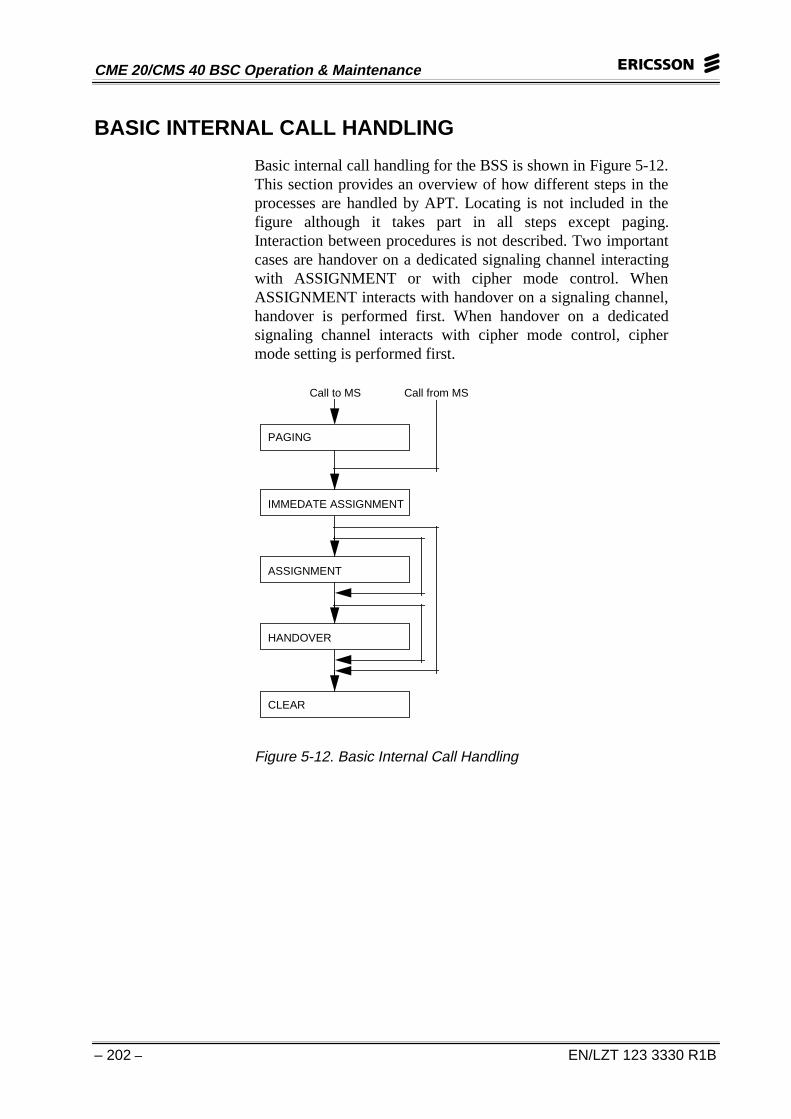
BASIC INTERNAL CALL HANDLING
Basic internal call handling for the BSS is shown in Figure 5-12.This section provides an overview of how different steps in theprocesses are handled by APT. Locating is not included in thefigure although it takes part in all steps except paging.Interaction between procedures is not described. Two importantcases are handover on a dedicated signaling channel interactingwith ASSIGNMENT or with cipher mode control. WhenASSIGNMENT interacts with handover on a signaling channel,handover is performed first. When handover on a dedicatedsignaling channel interacts with cipher mode control, ciphermode setting is performed first.
PAGING
IMMEDATE ASSIGNMENT
ASSIGNMENT
HANDOVER
CLEAR
Call to MS Call from MS
Figure 5-12. Basic Internal Call Handling
5 APT Subsystem
EN/LZT 123 3330 R1B – 203 –
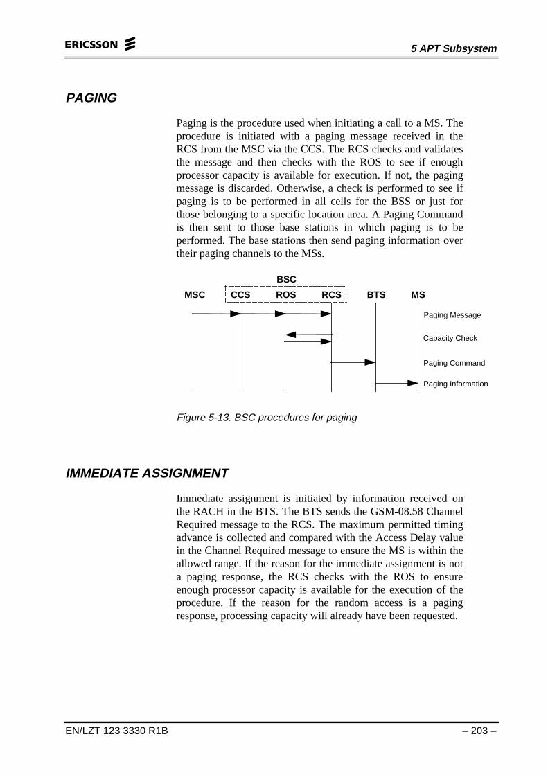
PAGING
Paging is the procedure used when initiating a call to a MS. Theprocedure is initiated with a paging message received in theRCS from the MSC via the CCS. The RCS checks and validatesthe message and then checks with the ROS to see if enoughprocessor capacity is available for execution. If not, the pagingmessage is discarded. Otherwise, a check is performed to see ifpaging is to be performed in all cells for the BSS or just forthose belonging to a specific location area. A Paging Commandis then sent to those base stations in which paging is to beperformed. The base stations then send paging information overtheir paging channels to the MSs.
MSC CCS ROS RCS BTS MS
Paging Message
Capacity Check
Paging Command
Paging Information
BSC
Figure 5-13. BSC procedures for paging
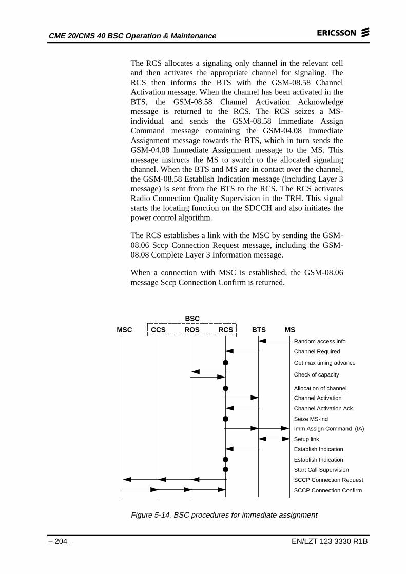
IMMEDIATE ASSIGNMENT
Immediate assignment is initiated by information received onthe RACH in the BTS. The BTS sends the GSM-08.58 ChannelRequired message to the RCS. The maximum permitted timingadvance is collected and compared with the Access Delay valuein the Channel Required message to ensure the MS is within theallowed range. If the reason for the immediate assignment is nota paging response, the RCS checks with the ROS to ensureenough processor capacity is available for the execution of theprocedure. If the reason for the random access is a pagingresponse, processing capacity will already have been requested.
CME 20/CMS 40 BSC Operation & Maintenance
– 204 – EN/LZT 123 3330 R1B
The RCS allocates a signaling only channel in the relevant celland then activates the appropriate channel for signaling. TheRCS then informs the BTS with the GSM-08.58 ChannelActivation message. When the channel has been activated in theBTS, the GSM-08.58 Channel Activation Acknowledgemessage is returned to the RCS. The RCS seizes a MS-individual and sends the GSM-08.58 Immediate AssignCommand message containing the GSM-04.08 ImmediateAssignment message towards the BTS, which in turn sends theGSM-04.08 Immediate Assignment message to the MS. Thismessage instructs the MS to switch to the allocated signalingchannel. When the BTS and MS are in contact over the channel,the GSM-08.58 Establish Indication message (including Layer 3message) is sent from the BTS to the RCS. The RCS activatesRadio Connection Quality Supervision in the TRH. This signalstarts the locating function on the SDCCH and also initiates thepower control algorithm.
The RCS establishes a link with the MSC by sending the GSM-08.06 Sccp Connection Request message, including the GSM-08.08 Complete Layer 3 Information message.
When a connection with MSC is established, the GSM-08.06message Sccp Connection Confirm is returned.
Random access info
Channel Required
Get max timing advance
Check of capacity
Allocation of channel
Channel Activation
Channel Activation Ack.
Seize MS-ind
Imm Assign Command (IA)
Setup link
Establish Indication
Establish Indication
Start Call Supervision
SCCP Connection Request
SCCP Connection Confirm
MSC CCS ROS RCS BTS MS
BSC
Figure 5-14. BSC procedures for immediate assignment
5 APT Subsystem
EN/LZT 123 3330 R1B – 205 –
ASSIGNMENT
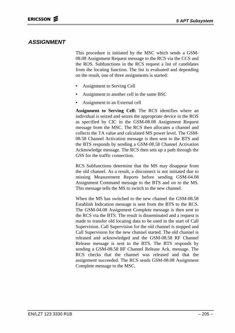
This procedure is initiated by the MSC which sends a GSM-08.08 Assignment Request message to the RCS via the CCS andthe ROS. Subfunctions in the RCS request a list of candidatesfrom the locating function. The list is evaluated and dependingon the result, one of three assignments is started:
• Assignment to Serving Cell
• Assignment to another cell in the same BSC
• Assignment to an External cell
Assignment to Serving Cell: The RCS identifies where anindividual is seized and seizes the appropriate device in the ROSas specified by CIC in the GSM-08.08 Assignment Requestmessage from the MSC. The RCS then allocates a channel andcollects the TA value and calculated MS power level. The GSM-08.58 Channel Activation message is then sent to the BTS andthe BTS responds by sending a GSM-08.58 Channel ActivationAcknowledge message. The RCS then sets up a path through theGSS for the traffic connection.
RCS Subfunctions determine that the MS may disappear fromthe old channel. As a result, a disconnect is not initiated due tomissing Measurement Reports before sending GSM-04.08Assignment Command message to the BTS and on to the MS.This message tells the MS to switch to the new channel.
When the MS has switched to the new channel the GSM-08.58Establish Indication message is sent from the BTS to the RCS.The GSM-04.08 Assignment Complete message is then sent tothe RCS via the BTS. The result is disseminated and a request ismade to transfer old locating data to be used in the start of CallSupervision. Call Supervision for the old channel is stopped andCall Supervision for the new channel started. The old channel isreleased and acknowledged and the GSM-08.58 RF ChannelRelease message is sent to the BTS. The BTS responds bysending a GSM-08.58 RF Channel Release Ack. message. TheRCS checks that the channel was released and that theassignment succeeded. The RCS sends GSM-08.08 AssignmentComplete message to the MSC.
CME 20/CMS 40 BSC Operation & Maintenance
– 206 – EN/LZT 123 3330 R1B
5
Assignment Request
Request candidate list
Seize device
Allocate channel
Collecting Timing Advance
Channel Activation
Channel Activation Ack
Setup path in GS
Inform that MS may disappear
Assignment Command
Setup link
Establish Indication
Assignment Complete
Inform about resultStop call supervision for old channelStart call supervision for new channel
MSC CCS ROS RCS GSS BTS MS
BSC
Assignment Complete
Release channel
RF channel release
RF channel release ack
Assignment succeeded
Figure 5-15. BSC procedures for assignment to serving cell
Assignment to Another Cell in the Same BSC: The RCSseizes the appropriate device in the ROS from the MSC andallocates a new traffic channel, as specified by CIC in the GSM-08.08 Assignment Request message. Channel information isverified and the GSM-08.58 CHANNEL ACTIVATIONMessage is sent to the BTS and the BTS responds by sending aGSM-08.58 Channel Activation Acknowledge message. TheRCS sets up a path through the GSS for traffic connection.
RCS Subfunctions determine that the MS may disappear fromthe old channel, so that a disconnect is not initiated due tomissing Measurement Reports. After this, the GSM-04.08Handover Command message is sent to the MS via the BTS.The MS receives this message and switches to the new channel.When the BTS is in contact with the MS it sends GSM-08.58Handover Detection message back to the RCS.
5 APT Subsystem
EN/LZT 123 3330 R1B – 207 –
Assignment Request
Request candidate list
Seize device
Allocate new channel
Channel Activation
Channel Activation Ack
Setup path in GS
Inform that MS may disappear
Handover Command
Handover Access Burst
Handover Detection
Establish Indication
Inform about resultStop call supervision for old channelStart call supervision for new channel
MSC CCS ROS RCS GSS BTS MS
BSC
Assignment Complete
Release channel
RF channel release
RF channel release ack
Handover succeeded
Get Max Timing Advance
Handover complete
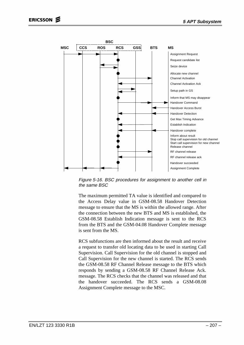
Figure 5-16. BSC procedures for assignment to another cell inthe same BSC
The maximum permitted TA value is identified and compared tothe Access Delay value in GSM-08.58 Handover Detectionmessage to ensure that the MS is within the allowed range. Afterthe connection between the new BTS and MS is established, theGSM-08.58 Establish Indication message is sent to the RCSfrom the BTS and the GSM-04.08 Handover Complete messageis sent from the MS.
RCS subfunctions are then informed about the result and receivea request to transfer old locating data to be used in starting CallSupervision. Call Supervision for the old channel is stopped andCall Supervision for the new channel is started. The RCS sendsthe GSM-08.58 RF Channel Release message to the BTS whichresponds by sending a GSM-08.58 RF Channel Release Ack.message. The RCS checks that the channel was released and thatthe handover succeeded. The RCS sends a GSM-08.08Assignment Complete message to the MSC.
CME 20/CMS 40 BSC Operation & Maintenance
– 208 – EN/LZT 123 3330 R1B
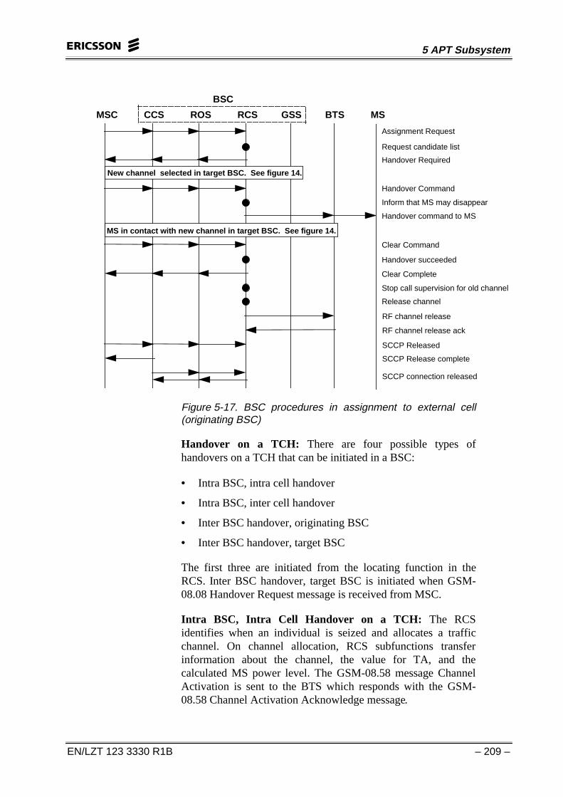
Assignment to an External Cell (In Originating BSC): TheRCS sends the GSM-08.08 Handover Required message to theMSC. This tells the MSC which cell the handover is to be madeto. The new channel is selected in the target BSC and the MSCsends the GSM-08.08 Handover Command message to the RCS.RCS subfunctions determine that the MS may disappear fromthe old channel, so that a disconnect is not initiated due tomissing Measurement Reports. The RCS then sends GSM-04.08Handover Command message to the MS telling it to switch to anew channel. The MS establishes contact with the new channelin the target BSC.
To clear the old connection, the MSC sends the GSM-08.08Clear Command message with handover cause “successfulhandover” to the RCS. The RCS changes the link and sends theGSM-08.08 Clear Complete message to the MSC. The RCSstops Call Supervision for the old channel and orders the releaseof the old channel. The GSM-08.58 RF Channel Releasemessage is sent to the BTS which responds by sending a GSM-08.58 RF Channel Release Ack. message. When the GSM-08.06SCCP Released message is received from the MSC, GSM-08.06SCCP Release Complete message is returned by the CCS and anindication that SCCP is disconnected is sent to the RCS.
Assignment to an External Cell (In Target BSC): BSCprocedures in the target BSC for external handover onassignment are identical to those for a handover on a trafficchannel BSC interwork in Target BSC for Inter BSC Handoveron TCH.
5 APT Subsystem
EN/LZT 123 3330 R1B – 209 –
497
Assignment Request
Request candidate list
MSC CCS ROS RCS GSS BTS MS
BSC
Handover command to MS
Inform that MS may disappear
Stop call supervision for old channel
Handover Required
Handover Command
Clear Command
Handover succeeded
Clear Complete
Release channel
RF channel release
SCCP Released
SCCP Release complete
RF channel release ack
SCCP connection released
New channel selected in target BSC. See figure 14.
MS in contact with new channel in target BSC. See figure 14.
Figure 5-17. BSC procedures in assignment to external cell(originating BSC)
Handover on a TCH: There are four possible types ofhandovers on a TCH that can be initiated in a BSC:
• Intra BSC, intra cell handover
• Intra BSC, inter cell handover
• Inter BSC handover, originating BSC
• Inter BSC handover, target BSC
The first three are initiated from the locating function in theRCS. Inter BSC handover, target BSC is initiated when GSM-08.08 Handover Request message is received from MSC.
Intra BSC, Intra Cell Handover on a TCH: The RCSidentifies when an individual is seized and allocates a trafficchannel. On channel allocation, RCS subfunctions transferinformation about the channel, the value for TA, and thecalculated MS power level. The GSM-08.58 message ChannelActivation is sent to the BTS which responds with the GSM-08.58 Channel Activation Acknowledge message.
CME 20/CMS 40 BSC Operation & Maintenance
– 210 – EN/LZT 123 3330 R1B
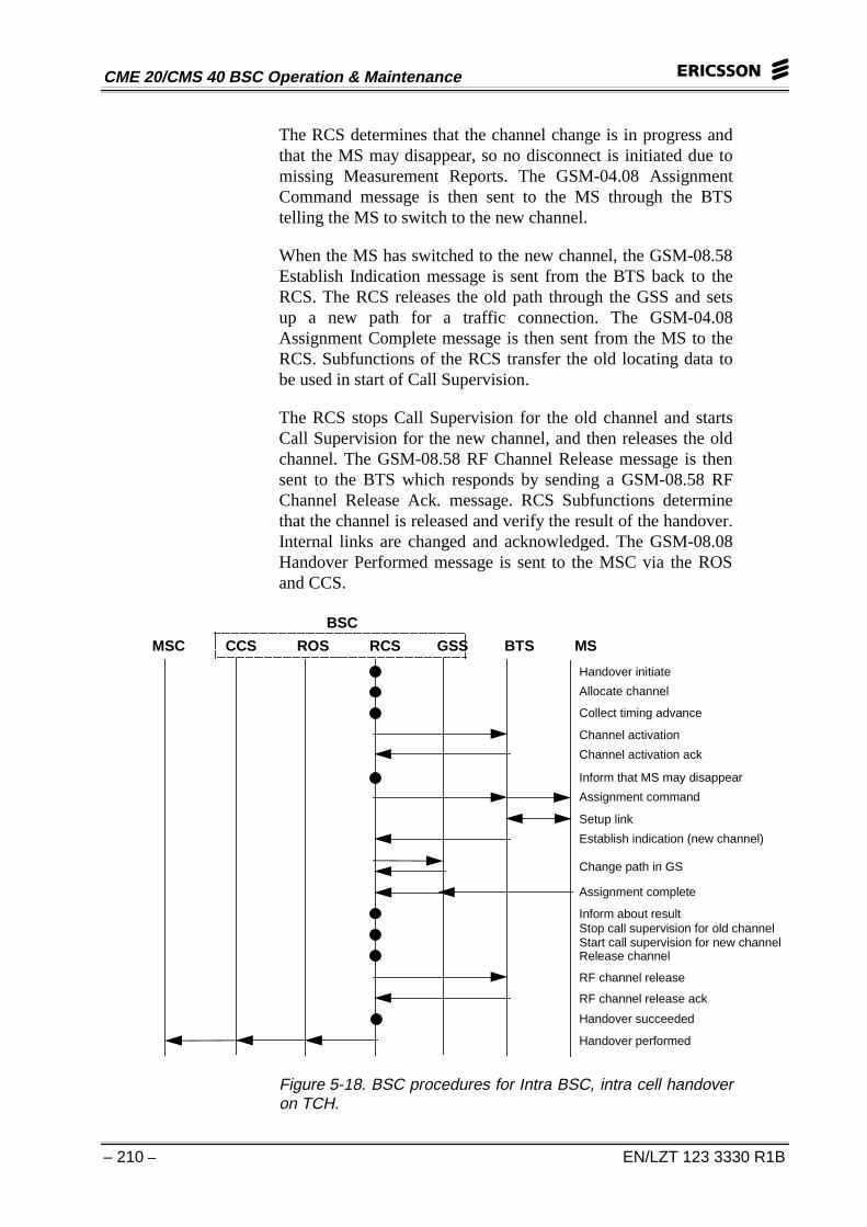
The RCS determines that the channel change is in progress andthat the MS may disappear, so no disconnect is initiated due tomissing Measurement Reports. The GSM-04.08 AssignmentCommand message is then sent to the MS through the BTStelling the MS to switch to the new channel.
When the MS has switched to the new channel, the GSM-08.58Establish Indication message is sent from the BTS back to theRCS. The RCS releases the old path through the GSS and setsup a new path for a traffic connection. The GSM-04.08Assignment Complete message is then sent from the MS to theRCS. Subfunctions of the RCS transfer the old locating data tobe used in start of Call Supervision.
The RCS stops Call Supervision for the old channel and startsCall Supervision for the new channel, and then releases the oldchannel. The GSM-08.58 RF Channel Release message is thensent to the BTS which responds by sending a GSM-08.58 RFChannel Release Ack. message. RCS Subfunctions determinethat the channel is released and verify the result of the handover.Internal links are changed and acknowledged. The GSM-08.08Handover Performed message is sent to the MSC via the ROSand CCS.
MSC CCS ROS RCS GSS BTS MS
BSC
Inform about resultStop call supervision for old channelStart call supervision for new channelRelease channel
Handover initiate
Allocate channel
Collect timing advance
Channel activation
Channel activation ack
Inform that MS may disappear
Assignment command
Setup link
Establish indication (new channel)
Change path in GS
Assignment complete
RF channel release
RF channel release ack
Handover succeeded
Handover performed
Figure 5-18. BSC procedures for Intra BSC, intra cell handoveron TCH.
5 APT Subsystem
EN/LZT 123 3330 R1B – 211 –
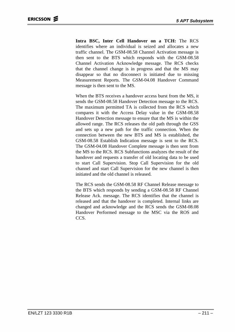
Intra BSC, Inter Cell Handover on a TCH: The RCSidentifies where an individual is seized and allocates a newtraffic channel. The GSM-08.58 Channel Activation message isthen sent to the BTS which responds with the GSM-08.58Channel Activation Acknowledge message. The RCS checksthat the channel change is in progress and that the MS maydisappear so that no disconnect is initiated due to missingMeasurement Reports. The GSM-04.08 Handover Commandmessage is then sent to the MS.
When the BTS receives a handover access burst from the MS, itsends the GSM-08.58 Handover Detection message to the RCS.The maximum permitted TA is collected from the RCS whichcompares it with the Access Delay value in the GSM-08.58Handover Detection message to ensure that the MS is within theallowed range. The RCS releases the old path through the GSSand sets up a new path for the traffic connection. When theconnection between the new BTS and MS is established, theGSM-08.58 Establish Indication message is sent to the RCS.The GSM-04.08 Handover Complete message is then sent fromthe MS to the RCS. RCS Subfunctions analyzes the result of thehandover and requests a transfer of old locating data to be usedto start Call Supervision. Stop Call Supervision for the oldchannel and start Call Supervision for the new channel is theninitiated and the old channel is released.
The RCS sends the GSM-08.58 RF Channel Release message tothe BTS which responds by sending a GSM-08.58 RF ChannelRelease Ack. message. The RCS identifies that the channel isreleased and that the handover is completed. Internal links arechanged and acknowledge and the RCS sends the GSM-08.08Handover Performed message to the MSC via the ROS andCCS.
CME 20/CMS 40 BSC Operation & Maintenance
– 212 – EN/LZT 123 3330 R1B
MSC CCS ROS RCS GSS BTS MS
BSC
Inform about resultStop call supervision for old channelStart call supervision for new channelRelease channel
Handover initiate
Allocate channel
Channel activation
Channel activation ack
Inform that MS may disappear
Handover command
Handover access burst
Handover detection
Change path in GS
Setup link
RF channel release
RF channel release ack
Handover succeeded
Handover performed
Get max timing advance
Handover complete
Establish indication
Figure 5-19. BSC procedures for Intra BSC, inter cell handoveron TCH
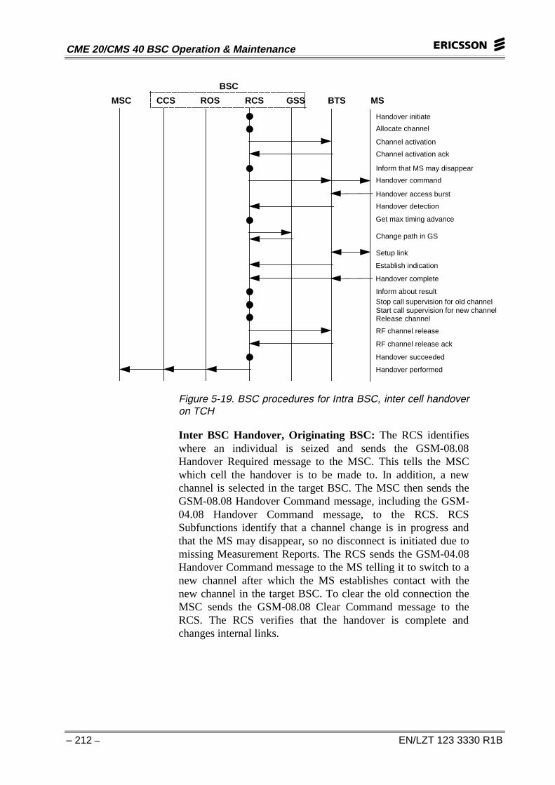
Inter BSC Handover, Originating BSC: The RCS identifieswhere an individual is seized and sends the GSM-08.08Handover Required message to the MSC. This tells the MSCwhich cell the handover is to be made to. In addition, a newchannel is selected in the target BSC. The MSC then sends theGSM-08.08 Handover Command message, including the GSM-04.08 Handover Command message, to the RCS. RCSSubfunctions identify that a channel change is in progress andthat the MS may disappear, so no disconnect is initiated due tomissing Measurement Reports. The RCS sends the GSM-04.08Handover Command message to the MS telling it to switch to anew channel after which the MS establishes contact with thenew channel in the target BSC. To clear the old connection theMSC sends the GSM-08.08 Clear Command message to theRCS. The RCS verifies that the handover is complete andchanges internal links.
5 APT Subsystem
EN/LZT 123 3330 R1B – 213 –
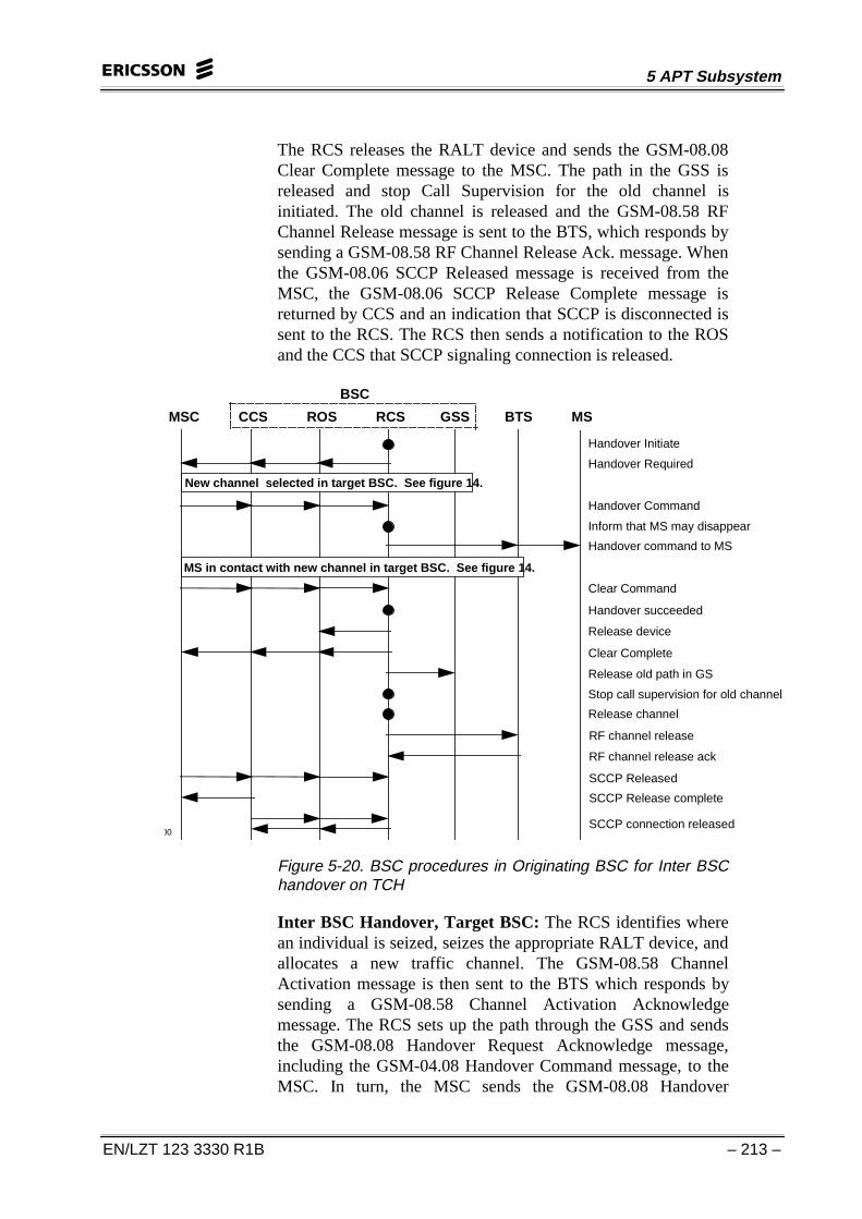
The RCS releases the RALT device and sends the GSM-08.08Clear Complete message to the MSC. The path in the GSS isreleased and stop Call Supervision for the old channel isinitiated. The old channel is released and the GSM-08.58 RFChannel Release message is sent to the BTS, which responds bysending a GSM-08.58 RF Channel Release Ack. message. Whenthe GSM-08.06 SCCP Released message is received from theMSC, the GSM-08.06 SCCP Release Complete message isreturned by CCS and an indication that SCCP is disconnected issent to the RCS. The RCS then sends a notification to the ROSand the CCS that SCCP signaling connection is released.
00
Handover Initiate
MSC CCS ROS RCS GSS BTS MS
BSC
Handover command to MS
Inform that MS may disappear
Stop call supervision for old channel
Handover Required
Handover Command
Clear Command
Handover succeeded
Clear Complete
Release channel
RF channel release
SCCP Released
SCCP Release complete
RF channel release ack
SCCP connection released
New channel selected in target BSC. See figure 14.
MS in contact with new channel in target BSC. See figure 14.
Release device
Release old path in GS
Figure 5-20. BSC procedures in Originating BSC for Inter BSChandover on TCH
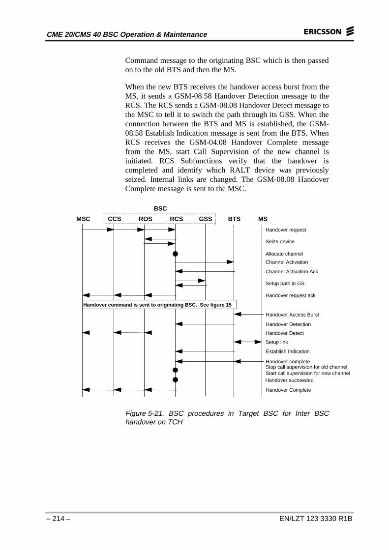
Inter BSC Handover, Target BSC: The RCS identifies wherean individual is seized, seizes the appropriate RALT device, andallocates a new traffic channel. The GSM-08.58 ChannelActivation message is then sent to the BTS which responds bysending a GSM-08.58 Channel Activation Acknowledgemessage. The RCS sets up the path through the GSS and sendsthe GSM-08.08 Handover Request Acknowledge message,including the GSM-04.08 Handover Command message, to theMSC. In turn, the MSC sends the GSM-08.08 Handover
CME 20/CMS 40 BSC Operation & Maintenance
– 214 – EN/LZT 123 3330 R1B
Command message to the originating BSC which is then passedon to the old BTS and then the MS.
When the new BTS receives the handover access burst from theMS, it sends a GSM-08.58 Handover Detection message to theRCS. The RCS sends a GSM-08.08 Handover Detect message tothe MSC to tell it to switch the path through its GSS. When theconnection between the BTS and MS is established, the GSM-08.58 Establish Indication message is sent from the BTS. WhenRCS receives the GSM-04.08 Handover Complete messagefrom the MS, start Call Supervision of the new channel isinitiated. RCS Subfunctions verify that the handover iscompleted and identify which RALT device was previouslyseized. Internal links are changed. The GSM-08.08 HandoverComplete message is sent to the MSC.
Handover request
Seize device
Allocate channel
Channel Activation
Channel Activation Ack
Setup path in GS
Handover Access Burst
Handover Detection
Establish Indication
Stop call supervision for old channelStart call supervision for new channel
MSC CCS ROS RCS GSS BTS MS
BSC
Handover Complete
Handover succeeded
Handover Detect
Handover complete
Handover request ack
Handover command is sent to originating BSC. See figure 15
Setup link
Figure 5-21. BSC procedures in Target BSC for Inter BSChandover on TCH
5 APT Subsystem
EN/LZT 123 3330 R1B – 215 –
HANDOVER ON A DEDICATED SIGNALING CHANNEL
Handover on a SDCCH or TCH signaling connection is almostidentical to handover on a traffic channel except that the locatingevaluation is started on SDCCH or TCH signaling connectionand some messages indicate signaling only. Furthermore, thereis no GS handling.
CLEAR OF A TRAFFIC CHANNEL
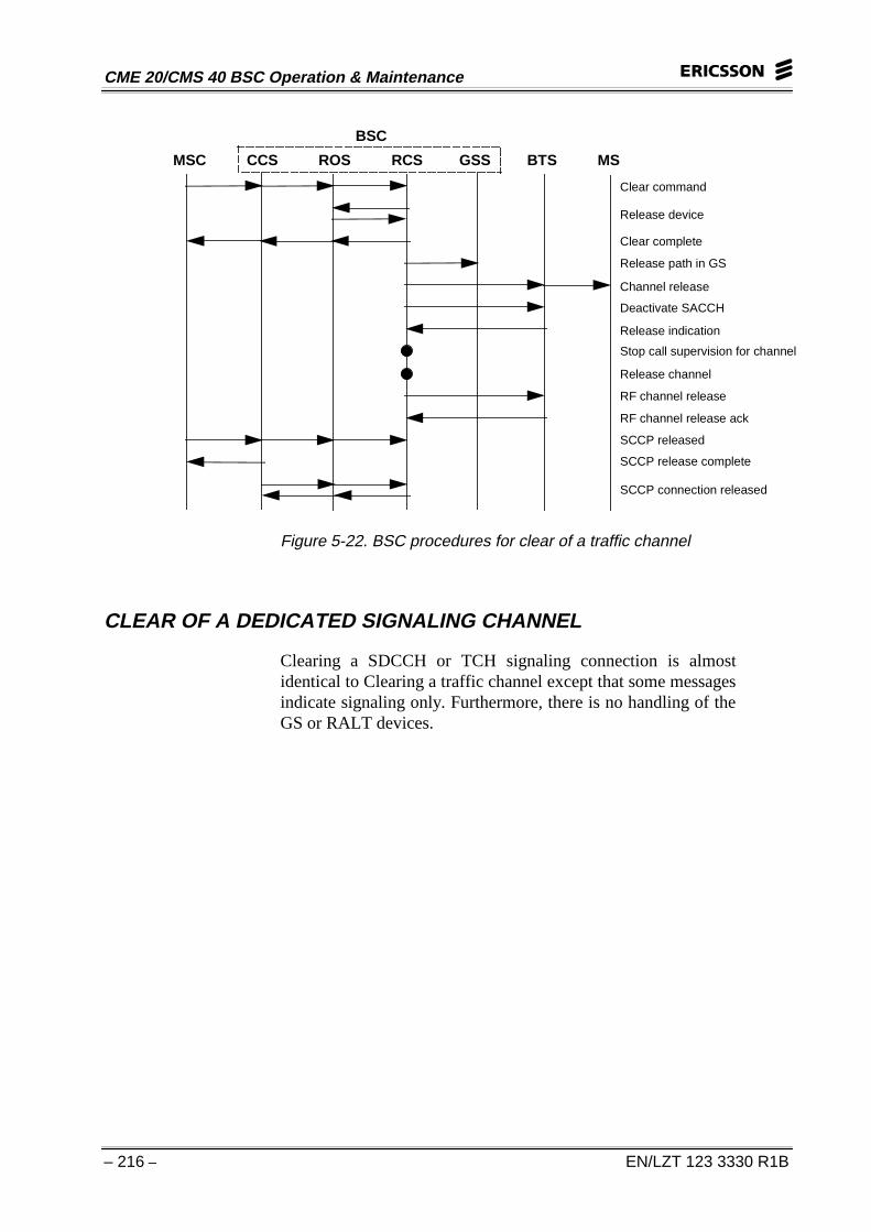
Clear is initiated by the MSC sending the GSM-08.08 ClearCommand message to the RCS which releases the seized devicein RALT. The GSM-08.08 Clear Complete message is then sentback to the MSC. The RCS releases the path in the GSS andsends the GSM-04.08 Channel Release message to the MS andthe GSM-08.58 Deactivate SACCH message to the BTS. TheBTS responds by sending a GSM-08.58 Release Indicationmessage. The RCS stops channel Call Supervision and releasesthe old channel. The GSM-08.58 RF Channel Release messageis sent to the BTS which responds with the GSM-08.58 RFChannel Release Ack. message. When the GSM-08.06 SCCPReleased message is received from the MSC, the GSM-08.06SCCP Release Complete message is returned by the CCS and anindication that SCCP is disconnected is sent forward to the RCS.The RCS sends an indication that the SCCP signalingconnection is released.
CME 20/CMS 40 BSC Operation & Maintenance
– 216 – EN/LZT 123 3330 R1B
Clear command
Release device
Release path in GS
Clear complete
Channel release
Deactivate SACCH
Release indication
Stop call supervision for channel
Release channel
RF channel release
RF channel release ack
SCCP released
SCCP release complete
SCCP connection released
MSC CCS ROS RCS GSS BTS MS
BSC
Figure 5-22. BSC procedures for clear of a traffic channel
CLEAR OF A DEDICATED SIGNALING CHANNEL
Clearing a SDCCH or TCH signaling connection is almostidentical to Clearing a traffic channel except that some messagesindicate signaling only. Furthermore, there is no handling of theGS or RALT devices.