Embed Size (px)
DESCRIPTION
preservation technology
Citation preview
Lighting the Way: A Conservator's Approach to Electrifying Brass ChandeliersAuthor(s): Kathy Z. Gillis and David HarveyReviewed work(s):Source: APT Bulletin, Vol. 31, No. 1, Lighting Historic House Museums (2000), pp. 45-51Published by: Association for Preservation Technology International (APT)Stable URL: http://www.jstor.org/stable/1504726 .Accessed: 12/10/2012 15:16
Your use of the JSTOR archive indicates your acceptance of the Terms & Conditions of Use, available at .http://www.jstor.org/page/info/about/policies/terms.jsp
.JSTOR is a not-for-profit service that helps scholars, researchers, and students discover, use, and build upon a wide range ofcontent in a trusted digital archive. We use information technology and tools to increase productivity and facilitate new formsof scholarship. For more information about JSTOR, please contact [email protected].
.
Association for Preservation Technology International (APT) is collaborating with JSTOR to digitize, preserveand extend access to APT Bulletin.
http://www.jstor.org
Lighting the Way: A Conservator's
Approach to Electrifying Brass Chandeliers
KATHY Z. GILLIS AND DAVID HARVEY
Two chandelier installation projects in the state of Virginia are detailed in
terms of approach, technique, electri-
fication, conservation, materials, and
handling.
Two projects that involved the conser- vation, electrification, and installation of historic and reproduction brass chandeliers were carried out indepen- dently by two cultural institutions in Virginia: the Colonial Williamsburg Foundation in Williamsburg and the Virginia Museum of Fine Arts in Rich- mond.
The approach and techniques for electrification differed according to the specific missions of each institu- tion and the nature and scope of the projects. Both projects, however, followed the long-term preservation goals and conservation objectives of the New Orleans Charter (reproduced in this issue of the APT Bulletin) and the Code of Ethics and Guidelines for Practice of the American Institute for Conservation of Historic and Artistic Works (AIC).' The predominant concern of both projects was for the safety and integrity of the historic object and its environs, from the use
... .. . . .
"? .1:.::. ... r..:...I:..:.......
................iii;; i•! ii n.,
....:; . ..
.
ii•; ? i•Y[::?.:::::
. :ii•!
fAlf
ii2'a sWO
.mn?
:':.:?: ?A :: t, " U Lim. W iZU, . . . . .............. . za - ,
of tested and approved conservation materials and reversible treatment methodologies to minimal interven- tion to the object.
Conservation Issues
Although all objects and environments are unique in many respects, metal objects share some common conserva- tion issues. For example, when metal objects are handled with bare hands, harmful substances, such as moisture, chloride salts, and long-chain alkyl esters of fatty acids secreted by pores (perspiration), are left on the surface. These substances are produced in the fingers and palms especially. Finger- print corrosion may remain invisible for a period of time, but when it does become noticeable, it is often too late; the imprints are already etched into the metal surface.2
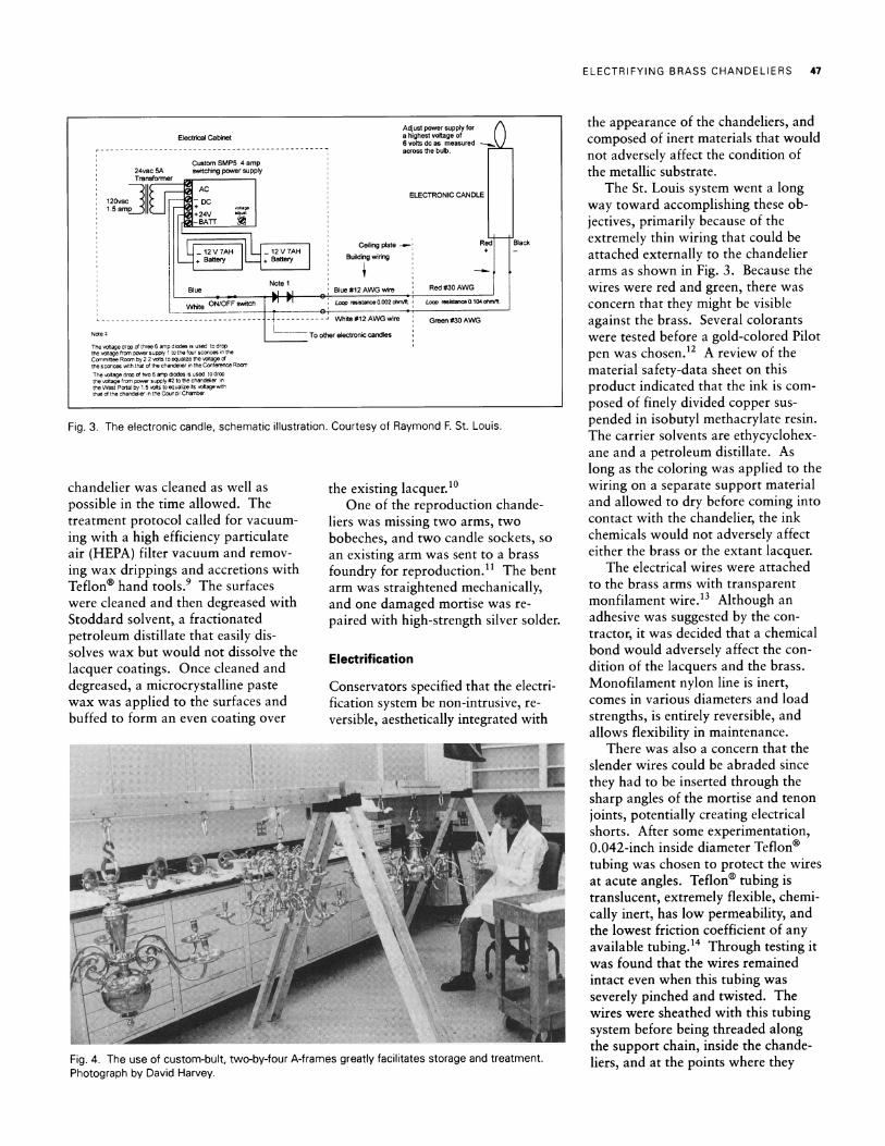
Damage to metal is also caused by the natural fatty acids in wax candles. Organometallic corrosion in the form of copper stearates and oleates dis- solves copper ions where wax has come into direct contact with brass.3 The candle sockets and bobeches (drip pans) on chandeliers suffer the most from this kind of damage (Fig. 1). Mechanical damage results from the repeated pressure of fitting new can- dles into the sockets. Brass chande- liers have long scroll arms with tenons that fit into mortises in the body of the chandelier. The arms are secured with retaining pins. When a new candle is shoved into the socket at the extended end of the arm, force is imposed on the mortise-and-tenon joint, a load-bearing element of the system. If there is any flaw in the casting or insufficient thickness, crack- ing, metal deformation, or even break- age can result (Fig. 2).
45
Fig. 1. Typical damage caused by the use of wax candles. Photograph by David Harvey.

46 APT BULLETIN
S.'i"
ur - . .4w
Fig. 2. Broken tenon on a chandelier arm from the use of candles. Photograph by David Harvey.
The historic building environment itself can cause damage. Dust can swirl around interior spaces, especially those with tall ceilings, because of convection and airflow patterns. Dust will settle onto a chandelier due to both the static charge of the metal and gravity. Dust can be abrasive and can also create a microenvironment on the surface that can retain moisture and become highly acidic. Particulate pollution leads to the formation of surface pits.4 Damage also results from pests, such as houseflies, that leave excreta (flyspecks) on exposed surfaces. Flyspecks are highly acidic and, like fingerprints, etch the surface of the object.
Damage occurs, too, from the typical maintenance of brass chande- liers. Old polish residues are often found trapped in the seams, pits, and details of the metal surface. These residues act much like dust and may, in their own right, contain corrosive and abrasive residues that are acti- vated by relative humidity.s
Many historic brass chandeliers were electrified from the 1930s to the 1960s. Evidence of this practice is found in old wiring remnants attached along chandelier arms and in drilled and plugged holes in the chandelier bodies, arms, bobeches, and sockets. This method of electrification is highly invasive to the objects, leaving them permanently altered. In the chandelier electrification projects at Williams- burg and Richmond, methodologies were developed to be minimally inva- sive and reversible.
The Colonial Williamsburg Chandelier Project
The lighting project at Colonial Williamsburg was undertaken during a major renovation to the reconstructed Capitol building on the eastern termi- nus of historic Duke of Gloucester Street. The renovation included instal- lation of electrical, fire detection and suppression, and security systems. All of the brass lighting devices used wax candles for illumination during evening programs and dark days. The electrifi- cation of the brass chandeliers and sconces within the Capitol represented the first large-scale effort to change traditional lighting in a major Colonial Williamsburg exhibition building.
The use of candles in a historic- house environment poses a direct threat to the safety of staff and visi- tors, the built environment, and the collections. Soot and candle wax directly affect brass lighting devices, as well as nearby collections and architectural finishes. The improved sensitivity of the new fire-detection system in the Capitol necessitated eliminating the use of candles to pre- vent false alarms.
The Metals and Arms Conservation Laboratory of Colonial Williamsburg had approximately eight weeks to examine and conserve six brass chan- deliers (two of which were historic), six reproduction sconces, and six reproduction candlesticks. Before the conservator was informed of the chan- delier project, a local company was already under contract to electrify chandeliers and sconces. Although the contract did not specify review and approval by conservators, the contrac- tor graciously agreed to a collabora- tive process.
The digital lighting systems were supplied by Ray St. Louis, of R.E St. Louis Associates.6 The St. Louis sys- tem was chosen because Colonial Williamsburg had used this system successfully in electrifying two repro- duction chandeliers in the Capitol in 1994. This system consists of an epoxy candle, cast from a silicone rubber mold of a real candle, with a sophisticated digital control board embedded in its interior (Fig. 3). The
board has power terminals on the bottom, an oscillator that can be tuned to a set frequency, and output leads that emerge into the candle top and into which a small three-quarter- watt replaceable bulb is inserted.7 A plastic sheath with metal clips fits over the bulb and creates the housing for the artificial candle flame. The wires for these candles have two conductors of AWG number 32 copper wire, each insulated with double-build poly- nylon insulation. One wire is red and the other green. The wires are bonded together with polyvinyl butyral.8
No conservator participated in the 1994 electrification project. In the 1998 project, the conservator first had to review, test, approve materials, and develop electrification methods. The conservator coordinated the research and treatment according to the needs of the lighting contractor's installation deadlines.
Treatment
The project required a mass-treatment methodology to stay within the project timetable. The metals laboratory and an adjacent laboratory space were used for the storage, treatment, and electrifi- cation of all the chandeliers and sconces. The Colonial Williamsburg Furniture Conservation Laboratory constructed several wooden A-frames from two-by-fours with steel eyebolts fastened to the underside of the top rail. These frames proved invaluable in the transport of the previously electri- fied chandeliers, as the chandeliers could not be disassembled without breaking the wiring. The frames also made it possible for the conservation staff to photograph and treat the chan- deliers in their hanging position, giving complete 360-degree access to the objects (Fig. 4). The frames were also used by the electrical contractor to thread the wiring into the chandeliers' interior elements and to join those wires with the pre-wired arms.
All of the chandeliers electrified in 1994 had suffered damages from improper handling, candle wax, dust, flyspecks, and previous cleanings, and all had extant lacquer coatings that appeared to be largely intact. Each
ELECTRIFYING BRASS CHANDELIERS 47
Adjust power supply for
Electrical Cabinet a highest voltage of 6 volts dc as measured - acrossthebulb.
Custom SMP5 4 amp 24vac 5A switching power supply Transformer
ELECTRONIC CANDLE 120 - DC 1.5 am+ volage
+24V " -BATT
Ceiling plate
'
Red Black S12 V 7AH 12 V 7AH +
+ Battery + BateryBuilding wiring
Note 1 Blue
Io
Blue #12 AWG wire Red #30 AWG
White ON/OFFswitch I Loop resistance0.002 ohnVft. Loop resistance0.104ohmlft.
L -------------------------- .-------- White #12 AWG wire Green #30 AWG
Note 1 To other electronic candles
The voltage drop of three 6 amp diodes is used to drop the voltage from power supply 1 to the four sconces in the Committee Room by 2.2 volts to equalize the voltage of the sconces with that of the chandelier in the Conference Room The voltage drop of two 6 amp diodes is used to drop the voltage from power supply #2 to the chandelier in the West Portal by 1.5 volts to equalize its voltagewith that of the chandelier in the Council Chamber
Fig. 3. The electronic candle, schematic illustration. Courtesy of Raymond F. St. Louis.
chandelier was cleaned as well as possible in the time allowed. The treatment protocol called for vacuum- ing with a high efficiency particulate air (HEPA) filter vacuum and remov- ing wax drippings and accretions with
Teflon? hand tools.' The surfaces were cleaned and then degreased with Stoddard solvent, a fractionated petroleum distillate that easily dis- solves wax but would not dissolve the lacquer coatings. Once cleaned and degreased, a microcrystalline paste wax was applied to the surfaces and buffed to form an even coating over
the existing lacquer.10 One of the reproduction chande-
liers was missing two arms, two bobeches, and two candle sockets, so an existing arm was sent to a brass foundry for reproduction." The bent arm was straightened mechanically, and one damaged mortise was re- paired with high-strength silver solder.
Electrification
Conservators specified that the electri- fication system be non-intrusive, re- versible, aesthetically integrated with
71,
.,.
ii ?i• :?
:"
....... .........
. . . .M
... .- \
Fig. 4. The use of custom-bult, two-by-four A-frames greatly facilitates storage and treatment. Photograph by David Harvey.
the appearance of the chandeliers, and composed of inert materials that would not adversely affect the condition of the metallic substrate.
The St. Louis system went a long way toward accomplishing these ob- jectives, primarily because of the extremely thin wiring that could be attached externally to the chandelier arms as shown in Fig. 3. Because the wires were red and green, there was concern that they might be visible against the brass. Several colorants were tested before a gold-colored Pilot pen was chosen.12 A review of the material safety-data sheet on this product indicated that the ink is com- posed of finely divided copper sus- pended in isobutyl methacrylate resin. The carrier solvents are ethycyclohex- ane and a petroleum distillate. As long as the coloring was applied to the wiring on a separate support material and allowed to dry before coming into contact with the chandelier, the ink chemicals would not adversely affect either the brass or the extant lacquer.
The electrical wires were attached to the brass arms with transparent monfilament wire.13 Although an adhesive was suggested by the con- tractor, it was decided that a chemical bond would adversely affect the con- dition of the lacquers and the brass. Monofilament nylon line is inert, comes in various diameters and load strengths, is entirely reversible, and allows flexibility in maintenance.
There was also a concern that the slender wires could be abraded since they had to be inserted through the sharp angles of the mortise and tenon joints, potentially creating electrical shorts. After some experimentation, 0.042-inch inside diameter Teflon? tubing was chosen to protect the wires at acute angles. Teflon" tubing is translucent, extremely flexible, chemi- cally inert, has low permeability, and the lowest friction coefficient of any available tubing.14 Through testing it was found that the wires remained intact even when this tubing was severely pinched and twisted. The wires were sheathed with this tubing system before being threaded along the support chain, inside the chande- liers, and at the points where they

48 APT BULLETIN
.. ....... . . . . ...... . ...... -MM M ', M
M?R M. ?'Z' MR Og- M W Mn ............... ... ......... un. kM? 8 "n ?P ir Mn -ff ............ ........... . ng? -a
P= m 'mm gmk- NORNMR, W. m 'Kl,?? ................. .
..... ........... PM .......... m zn, xi-'MH 0 ms R?jr .......... SUM MM" LAMM. ........... M., E I U 1 M, t"MR-IMEM OV . .......... 01,?gv F- E -a ? i2 nm? 8 ?,s om I -ul
?,, ?? i
" , M's
M-m .......... M MI-I'lln-I Mil
............ M,? 'n W ........ n? . ... PM M.E ? - -n MMM .......... MOn *?MM -.2M
M11"If4l IWnIHS1111 -- . i X "N 1?1
OPF
-M -MM;?
........... M. #44 A, 0? ...... .........
U ....... . ............ ................ ............................... .. .. ............... 2 ................. ...... . .............. ............ I ........ ............ - na. ?n,-n *=UM: IM MI ws=?.-nn,-mm 11GWM R ? ? iffiffl-, , R HUM AN. ............. X-'s ....... g. .... ..... ... M m a ?-z Ml . ..... M MR? R n-, P-m,
'Ra A-5 Mnh m M, nM 41 ?NIMM ........ ..... .....
Fig. 5. Completed chandelier with the St. Louis candle system. Note the barely visible monofila- ment ties on some of the arms. Photograph by Jennifer Zemanek.
would be connected to each arm. The finished installation of the wiring is virtually invisible from several feet away but can it be seen at six inches from the chandelier (Fig. 5).
Another challenge was to run the wiring through the bobeches and the sockets. Washers were tested to fit between these two parts, but existing wear on the brass threads was such that the sockets barely tightened; the addition of a washer left the socket too loose to be secure. On some of the chandeliers this was not a prob- lem, because the threaded ends of the sockets were hollow. However, on others, the choice was either to run the wires over the tops of the bobeches and candle sockets or to unplug some of the previously plugged holes. Because the wires were too visible with the first approach, some of the brass plugs were removed. The plugs consisted of modern threaded screws with filed-off heads. Most of them could be removed quite easily, using moderate encouragement, with a hand punch and hammer. The sockets were turned so that the holes faced back toward the center of the chande- lier and were not visible.
The epoxy candles were secured
within the sockets with a sheath of Volara,? a flexible, closed-cell poly- ethylene foam, which was wrapped around each candle until the candles were secure but could still be adjusted slightly. is There was concern that the faux flames looked too white and artificial, so the plastic sheaths that covered the candle bulbs were inpainted with an acrylic paint, and a very natural-looking flame was achieved.16
The Virginia Museum of Fine Arts Chandelier Project
In the original 1936 entrance hall of the Virginia Museum of Fine Arts hangs a recently acquired seventeenth- century Dutch or Flemish brass chan- delier (Fig. 6). No longer used as an entry, the space is still visible from the second-story galleries and features a grand staircase and a thirty-eight-foot- high ceiling. Three Palladian windows provide natural illumination. The antique chandelier was acquired as part of an overall refurbishment of the museum's central gallery areas, which have neoclassical details in ornamental columns, a large central boss from which to hang a central light fixture,
recessed clerestory windows, and ex- tensive decorative millwork.
The chandelier is of superior craftsmanship and design and has suffered little damage since its man- ufacture around 1690. During the baroque period, the main center for making chandeliers was Flanders, which imported them throughout Europe and England. The typical baroque shape of the museum's chandelier remained popular well into the eighteenth century and was revived during the empire period. Such chandeliers were common in continental and English upper class homes, as well as churches, where the scale was necessarily larger. The museum's chandelier is of a type that may have been found in the grand entrance hall of an English country house, which the architec- tural space of the museum's en- trance hall recalls.
Plans for cleaning, electrifying, and installing this massive artifact (which weighs nearly three-hundred pounds) began well before the chandelier ar- rived. The installation would be both a technical and a physical challenge. A mounting system was designed to allow the chandelier to be lowered for cleaning and changing light bulbs (to erect scaffolding each time mainte-
U f:,::' ?";; ?
Nt..
"Ut...
. . . . . . . . . .-a::;
Fig. 6. Chandelier as installed in the 1936 entrance to the Virginia Museum of Fine Arts. Photograph by Denise Lewis, ? 1998, Virginia Museum of Fine Arts.
ELECTRIFYING BRASS CHANDELIERS 49
nance was required would be imprac- tical). As with most projects of this magnitude and complexity, staff ex- perts from many departments were included in the planning and imple- mentation: curatorial, conservation, registration, production design and lighting, and building engineering.
Research
Various electrification and hanging systems were thoroughly researched. After consulting with Colonial Williamsburg and the Winterthur Mu- seum (both had recently undertaken chandelier electrification projects), a design and plan were developed. The custom-made epoxy candles from the St. Louis system described above were chosen for the project, and the electrifi- cation procedure would be performed in house, utilizing the museum staff's expertise. The realistic appearance of the St. Louis system candles and their very thin wires met both conservation and aesthetic criteria.
Condition
The physical condition of the chandelier was first thoroughly documented by a written report, a schematic drawing, and photography of each component. The chandelier has two tiers consisting of eight arms each. It had been previously electrified, as evidenced by a remaining insulated copper wire attached to one of the long arms with metal wire. This wire was one-quarter inch in diameter with a clear casing, dating from the 1960s or 1970s. There are several brass plugs in the central brass mortised components, indicative of a previous electrification campaign. Unplugged holes still exist in the internal iron rod that extends from the bottom finial and continues through to the top of the chandelier. The iron rod contained a fragment of fabric- covered electrical cord of a type used around 1920 to 1940. The chandelier arrived from England disassembled into its seventy-one component parts. Each element was slightly tarnished, and there were numerous fingerprints, several of which appeared old and had long since been etched into the metal surface. A few components appeared to have a
wax-like coating, and there was no evidence of a lacquer coating.
Treatment
The goal of the treatment was to remove existing tarnish and fingerprints and to protect the surface from future tarnish- ing. Since the chandelier would be installed thirty feet above the floor, it was unlikely that it would receive regu- lar maintenance. Aesthetically, it was desirable to retain a bright metallic surface. For these reasons, it was appro- priate to apply a reversible lacquer coating. Residues were first removed from all surfaces with Stoddard solvent. The next step was polishing to remove fingerprints and tarnish. A study carried out by Wharton, Maisch, and Ginell on abrasive polishes for silver was con- sulted for appropriate cleaning materials because the study's conclusions are also relevant for brass.17 To remove finger- prints and tarnish from the metal sur- faces alpha alumina powder was mixed into a paste with ethanol.18 After clean- ing, the surfaces were wiped with ethanol to remove any residues from polishing, then swabbed with acetone for further degreasing. The individual pieces were coated with a nitrocellulose- based lacquer chosen for its ease of application, aesthetic qualities, and
r 1~
'I "' f!
: •:
?
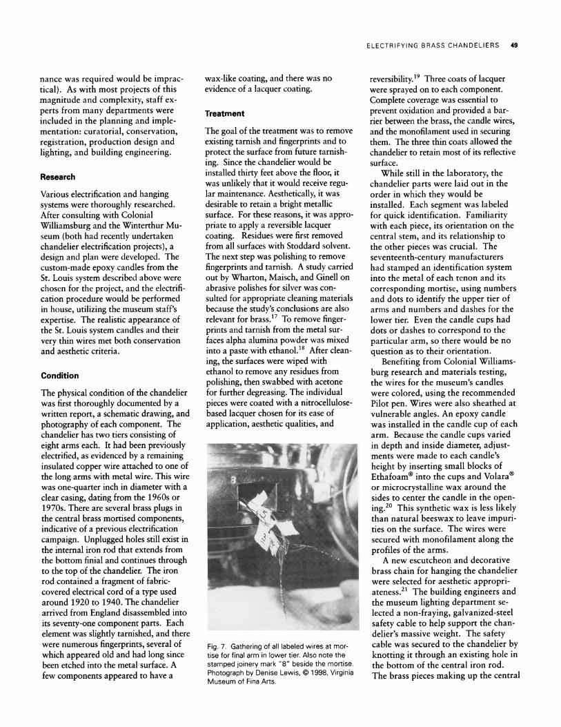
Fig. 7. Gathering of all labeled wires at mor- tise for final arm in lower tier. Also note the stamped joinery mark "8" beside the mortise. Photograph by Denise Lewis, @ 1998, Virginia Museum of Fina Arts.
reversibility.19 Three coats of lacquer were sprayed on to each component. Complete coverage was essential to prevent oxidation and provided a bar- rier between the brass, the candle wires, and the monofilament used in securing them. The three thin coats allowed the chandelier to retain most of its reflective surface.
While still in the laboratory, the chandelier parts were laid out in the order in which they would be installed. Each segment was labeled for quick identification. Familiarity with each piece, its orientation on the central stem, and its relationship to the other pieces was crucial. The seventeenth-century manufacturers had stamped an identification system into the metal of each tenon and its corresponding mortise, using numbers and dots to identify the upper tier of arms and numbers and dashes for the lower tier. Even the candle cups had dots or dashes to correspond to the particular arm, so there would be no question as to their orientation.
Benefiting from Colonial Williams- burg research and materials testing, the wires for the museum's candles were colored, using the recommended Pilot pen. Wires were also sheathed at vulnerable angles. An epoxy candle was installed in the candle cup of each arm. Because the candle cups varied in depth and inside diameter, adjust- ments were made to each candle's height by inserting small blocks of Ethafoam? into the cups and Volara? or microcrystalline wax around the sides to center the candle in the open- ing.2" This synthetic wax is less likely than natural beeswax to leave impuri- ties on the surface. The wires were secured with monofilament along the profiles of the arms.
A new escutcheon and decorative brass chain for hanging the chandelier were selected for aesthetic appropri- ateness.21 The building engineers and the museum lighting department se- lected a non-fraying, galvanized-steel safety cable to help support the chan- delier's massive weight. The safety cable was secured to the chandelier by knotting it through an existing hole in the bottom of the central iron rod. The brass pieces making up the central

50 APT BULLETIN
stem were lined up in order on blan- kets, with carpeted blocks used for padding and support. Both the cable and an electrical lead wire were guided through the iron rod and each brass element of the central stem. Individual candle wires from each arm of the chandelier would later be connected to this lead wire. The safety cable and electrical lead wire were threaded through the decorative chain.
Installation
The stem assembly without the arms yet attached was hoisted upright with the aid of a hydraulic manual engine hoist. A hand-cranked winch was installed in the ceiling. While hanging, the weight of the chandelier stem was transferred from the manual engine hoist to the hand- cranked winch in the ceiling. A manual winch was recommended over an electri- cal winch for use in areas where people could be hurt if the electrical system failed and the load accidentally dropped.22
The chandelier was first raised without the arms in place to test the final height and to determine the place- ment of a new ceiling escutcheon within the existing central architectural detail. Watching from the floor, one staff member communicated via radio headphones with her assistant, who was located at the winch above the ceiling. The escutcheon placement was marked from above the ceiling, so that when the chandelier was launched aloft fully assembled minimum adjust- ments would be necessary.
Once the final position was marked, the chandelier stem was again lowered and its weight transferred back to the engine hoist for insertion of the arms. Each electrical wire had been labeled with its corresponding arm number. A length of cotton twill tape was inserted into each mortise to thread a corre- sponding wire into the stem. Once this step was completed for all mortises, the eight wires for each tier were pulled together at the mortise for arm number eight on each tier (Fig. 7). This was done to make it easier to execute any future electrical repairs, so that only one arm would have to be removed to access the wires. Labeling the wires
ensured that each wire could be lo- cated easily and accurately in the fu- ture. The gathered wires were soldered to the electrical lead wire running from the ceiling and then inserted into a hollow brass piece in the central stem. Once the wire bundles were completed, the final arm could be installed.
Before raising the chandelier into position, electricity was supplied to the entire assembly to check that all lights worked and to be sure that there were no short circuits or crimped wires. The weight of the assembly was again transferred from the manual engine hoist back to the winch in the ceiling, and the chandelier was raised into place. The transformer for the candles and all electrical components are lo- cated above the ceiling rather than inside the chandelier's central core. By locating them apart from the chande- lier, maintenance can be carried out without having to disassemble the chandelier.
Now that the chandelier is in place, it lends an air of elegance and grandeur to the 1936 stair hall. The faux can- dles give the appearance of soft, flicker- ing illumination, much like real candle- light.
Conclusion
The faux candle lighting system is an appealing one from a conservator's point of view because it provides a naturalistic ambiance while eliminating the signifi- cant and ongoing damage caused by the use of candles. The system is intended only as an accent and not as the primary source of illumination of historic interi- ors and objects. The St. Louis system works perfectly in the context of the Virginia Museum of Fine Arts installa- tion. At Colonial Williamsburg, two problems were discovered after the chandeliers and wall sconces were re- installed in the Capitol. First, interpre- tive personnel and visitors, accustomed to real candlelight during evening events, did not have the illumination necessary to conduct programs safely. Second, the rate of flickering of the faux candles, which is specified before manufacture, caused an irritating strobe effect. The digital chip responsible for the rate of flicker is adjustable, but only in the
manufacturing stage of the candles. It is permanently installed within the epoxy candle and cannot be removed or changed once installed unless the entire candle is replaced. Colonial Williams- burg resolved the latter issue with the installation of in-line resistors (3.6-ohm, one-quarter-watt) that reduced the depth of the flicker by closing the difference between the "high" brightness of the bulb and the "low" brightness of the bulb during the flicker.23
Both projects showed that a methodology of sound conservation practices can be successfully employed. Any lighting system designed and adapted for a historic structure must take all factors into account, such as ambient room light, placement of windows and curtains, highly reflective surfaces, such as polished metals and looking glasses, and also the intended programmatic use of the spaces, day or night. Goals must be articulated early and clearly and include all those in- volved.
The importance of planning and communication in such projects cannot be overemphasized. The lighting re- quirements of historic interiors need to be carefully designed for each situa- tion. Engaging a knowledgeable light- ing designer and preparing and testing with mock-ups is essential. Sharing experiences in formulating a safe and effective approach to the conservation, electrification, and installation of his- toric brass chandeliers may illuminate the way for colleagues who undertake similar projects.
Acknowledgments
As with most projects of this magnitude, many people were involved. We were fortunate in that we could easily consult with each other. At Colonial Williamsburg, the authors would like to thank curators Tanya Wilson and John Davis, object conservator Scott Nolley, conser- vation technician Sara Sphargel, conservation intern Jennifer Zemanek, and John Sands, Director of Collections and Conservation; Raymond St. Louis, of R.EF St. Louis Associates in Branchville, New Jersey; and lighting con- tractor Brenda Duros of the Lamplighter Shoppe in Williamsburg. At the Virginia Museum of Fine Arts, the authors would like to thank director Katharine C. Lee, curator Kath- leen Schrader, conservator Katharine Untch, exhibition designer Tom Baker, exhibition lighting designer Mary Brogan, lighting techni- cian Martha Pittinger, electrician Mike Owens,

ELECTRIFYING BRASS CHANDELIERS 51
registrar Maureen Morrisette, and photogra- phers Katherine Wetzel and Denise Lewis. We would also like to acknowledge the time and assistance given to us by professionals at other institutions, specifically, Gregory Landrey and Mary Jane Robinson at the Winterthur Museum and Gardens and Beverly Perkins, conservator in private practice in Murrieta, California.
KATHY Z. GILLIS is Assistant Objects Conservator at the Virginia Museum of Fine Arts. She completed her academic conservation training at the University of Delaware/Win- terthur Museum and has worked at the J.Paul Getty Museum, the Fine Arts Museums of San Francisco, and the Oakland Museum of Califor- nia.
DAVID HARVEY is Associate Conservator of Metals and Arms at the Colonial Williams- burg Foundation in Williamsburg, Virginia. He has been a conservation professional since 1988.
Notes
1. APT/AIC New Orleans Charter for the Joint Preservation of Historic Structures and Artifacts outlines the principles adopted by the Associa- tion for Preservation Technologies (APT) and the American Institute for Conservation (AIC) for balancing the often conflicting conservation requirements of historic structures and the artifacts housed in them. See: APT Bulletin, this issue. The Code of Ethics and Guidelines for Practice define appropriate conduct for the conservation professional. See Directory for the AIC, 2000, pp. AIC22-28, or web page at http://aic.stanford.edu.
2. For the effects of improper handling on metal objects see: Terry Drayman-Weisser, "Metal Objects," in Caring For Your Collec- tions (New York: Harry N. Abrams, 1992), 110. For the chemistry of fingerprints see: "Vanishing Clues: A detective noticed some- thing strange about kid's fingerprints - they disappear. Lab researchers are seeking ways to recover this important evidence," in Lab Notes Oak Ridge National Laboratory 50 (January 1995): 1-2.
3. For a recent explanation of fatty-acid corro- sion see: Janet L. Schrenk, "The Royal Art of Benin: Surfaces, Past and Present," in Ancient and Historic Metals; Conservation and Scientific Research (Malibu: The J. Paul Getty Trust, 1994), 57-59.
4. Philip A. Schweitzer, "Atmospheric Corro- sion," in Corrosion and Corrosion Protection Handbook (New York: Marcel Decker, 1989), 27.
5. "The Cleaning, Polishing and Protective Waxing of Brass and Copper," CCI Notes The Canadian Conservation Institute, Ottawa, Canada 9 (3:1997): 1-2.
6. R.F. St. Louis, Innovative Engineering, Branchville, N.J. 07826.
7. U.S. Patent 5,600,209, 1997. Also, Ray St. Louis, personal conversation with the author, November 2, 1998.
8. Technical data sheet on Multifilar Magnet Wire, part No. B-2322211, MHS Wire Indus- tries, Westlake Village, Calif.
9. The high efficiency particulate air (HEPA) filter traps ultrafine dust particles down to and including 0.3 microns and prevents recircula- tion. Teflon@ "policeman" is distributed by Conservation Support Systems, P.O. Box 91746, Santa Barbara, Calif. 93190-1745.
10. Renaissance Wax manufactured by Picre- ator Renaissance Products by Picreator Enter- prises, Ltd., 44 Park View Gardens, London NW4 Eng.
11. Replacement brass components were cast and finished by C.A. Brown, 315 Wellington Ave., Cranston, R.I.
12. Pilot Gold Marker, extra fine point; copper and aluminum in ethylcyclohexane and petroleum distillate, manufactured and dis- tributed by Pilot Corporation of America, Trumbull, Conn. 06611
13. Monofilament wire manufactured and distributed by Berkeley Outdoor Technologies Group, Spirit Lake, Ia.
14. Polytetrafluoroethylene (PTFE) microbore tubing #06417-41 distributed by Cole-Parmer Instrument Company, Vernon Hills, Ill. 60061- 9872.
15. Volara@ polyethylene foam, distributed by Merriweather Foam, Barberton, Oh.
16. Liquitex acrylic paint, manufactured by Binney & Smith, Easton, Pa. 18044-0431.
17. Glenn Wharton, Susan Maish, and William Ginell, "A Comparative Study of Silver Cleaning Abrasives," Journal of the American Institute for Conservation 29 (1: 1990): 13-31.
18. Buehler's Micropolish II, deagglomerated alpha alumina, 1.0 micron, manufactured and distributed by Buehler, Lake Bluff, Ill. 60044.
19. Agateen Lacquer Number 8A, cellulose nitrate and polyester resin; manufactured and distributed by Agate Lacquer Manufacturing Co., Long Island City, N.Y. 11101.
20. Ethafoam@ distributed by Advanced Packaging, Baltimore, Md. Multiwax number W-835 microcrystalline wax distributed by Conservation Support Systems, Santa Barbara, Calif. 93190-1745
21. The brass chain and escutcheon were obtained from Jefferson Lighting and Glass, Lynchburg, Va 20506.
22. As noted in the 1998 edition of W.W. Grainger, manufacturer and distributor of electric winches, Lincolnshire, Ill.
23. Brenda Duros, facsimile to author, Williamsburg, Va., September 1, 1999.
HYDRESTORATION CLEANING SYSTEMS RESTORATION CLEANING SYSTEMS
?I~E;cf~i~OC~;"
-~it J ~i~c
~L~Si~- RL
/ nli
r)r7~
i~r - o~j~~ ;de~
r "
GIVE YOUR BUILDING THE HYDROCLEAN? LOOK Hydroclean restoration cleaning systems are the finest restoration products available today. They have been used in numerous restoration projects that include the interior of the U.S. Capitol, the exterior of the White House, the Cooper Hewitt Museum, Thomas Jefferson's Monticello and the Connecticut State Capitol. The HYDROCLEAN systems are unique in that they have been developed by contractors for contractors. A contracting company's existence depends on its ability to meet production schedules and budgets in today's increasingly competitive market. HYDROCLEAN offers practical products that work as specified the first time. The HYDROCLEAN philosophy is to provider owners/architects and restoration contractors proven high pressure water and chemical cleaning technology that will give consistent results, is safe, biodegradable and cost effective.
For additional information please call (800) 278-7681 or write Hydrochemical Techniques, Inc., PO. Box 2078, Hartford, Conn. 06145.
Hydrochemical Techniques, Inc. www. hydroclean. com