Embed Size (px)
Citation preview

Instructions for use
Title Approximate Scalar Finite-Element Analysis of Anisotropic Optical Waveguides with Off-Diagonal Elements in aPermittivity Tensor
Author(s) Koshiba, M.; Hayata, K.; Suzuki, M.
Citation IEEE Transactions on Microwave Theory and Techniques, 32(6): 587-593
Issue Date 1984-01
Doc URL http://hdl.handle.net/2115/6043
Rights©1984 IEEE. Personal use of this material is permitted. However, permission to reprint/republish this material foradvertising or promotional purposes or for creating new collective works for resale or redistribution to servers or lists,or to reuse any copyrighted component of this work in other works must be obtained from the IEEE.IEEE, IEEE Transactions on Microwave Theory and Techniques, 32(6), 1984, p587-593
Type article
File Information ITMTT32_6.pdf
Hokkaido University Collection of Scholarly and Academic Papers : HUSCAP
~ . f EU TRANSACTIONS ON MICROWAVE TH EORY .... ND TECHNIQUES, VOL. MTI-32, NO.6, JUNE 1984 587
i Approximate Scalar Finite-Element Analysis I of Anisotropic Optical Waveguides with , Off-Diagonal Elements in a I Permittivity Tensor
I MASANORI KOSHIBA, SENIOR MEMBER, IEEE, KAZUYA HAYATA, AND
MICHIO SUZUKI, SENIOR MEMBER, IEEE
~ Ab.ftt"Qc' -An approximate scalar finite·element program for the analysis of anisotropic optical ... ·aveguides having a permltthity tensor with nonzero off-diagonal elements is described. In lhis approach, the nonphysical spurious solutions which are included in the solutions of the earlier vectorial finite-element method ;n an axial' components fonnulation Ilo not appear. Numerical examples on an allisotropie dielectric rectangular wa\'eguide composed of a uniaxial medium are given. Our results for the waveguide ... ·hose optic axis lies In the plane (xy-p1ane) nonnal to the direction (t -axis) of propagation agree ... -ell with the results of the vectorial wave analysis using the variational method. We also demonstrate the application of this approach by analyzing the anisotropic dielectric rectangular "lIveguide whose opfic axis lits In the Xt - or y t · plane.
I. I NTRODUCTION
Fig. 1. Three-dimensional optical waveguide gw metry.
SEVERAL METHODS FOR the analysis of a threedimensional optical waveguide such as sbown in Fig. 1
(where t is the height or depth and W is the width) have been proposed [I ] and the vectorial finite-element method in an axial components ( E, - Hz) fo rmulation, which en-ables one to compute accurately the mode spectrum of a finite-element formulation for the analysis of isotropic waveguide with arbitrary cross section, is widely used optical waveguides. This approach bas as its main ad[2]- [8]. However, the vectorial finite.element solutions have vantages: the smaller matrix dimensions, less computer been known to include nonphysical solutions [2]-[8]. If one time, no spurious modes (because functionals based on the wants to compute a set of eigenmodes it is difficult and . scalar approximation are positive definite [7]), and the very cumbersome to distinguish betwee~ the spurious and capability of easily computing higher order modes [7], [12], the physical Plodes of tbe guides. The cause of these [13]. . spurious modes is believed to be in the indefinite nature of In thiS paper, this approximate scalar finite-element the E1 - Hz variational formulation [6]- 18J. In addition, meth?rl. i~ extended t~ tbe anisotropic waveguides having a the vectorial finite-element method can be applied only to pernu~tlvlty tensor WIth nonzero off-diagonal elements. For anisotropic waveguides with a diagonal permittivity tensor two-dimensional waveguides (a/ax" 0) [14J- [17), the rna· (3), [7J. tfix equation derived by this approach is reduced to the
Recently, Steinberg and Giallorenzi (9J have formulated exact expression for two-dimensional guided modes [1 8). an approximate coupled mode treatment based on the (1 9). In order to study the accuracy of the method, various Marcatili method (1 0] for a uniaxial waveguide whose optic isotr?pic dielectric waveguides are analyzed and tbe results axis lies in the xz-plane, and Oh taka [I I) has analyzed a obtarned are compared with previously published results uniaxial waveguide whose optic axis Lies in the xy-plane [~] , (10)! [20). Then, numerical examples on an anisotropic using the variational method. Mabaya, Lagasse, and dlel~tnc rect~ngular waveguide composed of a uniaxial Vandenbulcke [7) have presented an approximate scalar m~1Um. ar~ &,iven. Our results for the waveguide whose
Manuscript ra:eived June 15, 1983; revised January 3, 1984. The authors arc with the Department of Ele<: tronic Engineering, Hok
kllido University, Sapporo, 060, Japan.
OptiC axJs Ites ID the xy·plane agree well with the results of the vectorial wave analysis using the variational method [11]. We also demonstrate the application of this approach by analyzing the anisotropic dielectric rectangular waveguide whose optic axis lies in the xz· or yz-plane.
0018-9480/84/0600-0587$01.00 "'1984 IEEE
58' I ~t[ TRANSACflOf"S ON MICROWAV E THEORY AND TECHNIQUES, VOL. MTT-32. NO.6, JUNE 1984
II . ApPROXIMATE BASIC EQUATIONS
We consider a three-dimensional anisotropic waveguide in Fig. 1 having a permittivity tensor with all nonzero off-diagonal ~lements (oK'j (i, j = x, y, z) and the penneability of free space J.i-o. where ( 0 is the permittivity of free space and Kij is the relative permiuivity.
Maxwell's equations are, in component form
Substituting (7) into (16), we obtain
E 1 1 [ , K" a (aH, JH, ) y = -" - jk:KuHx + -:--k -a -a +-a j W( o a j z x x y
aH'l b ( - Ky: 8y - (i Ex" 17)
Considering (10)-(12) and eliminating Ey between (5)
iJE./ily+ jklEy = - jWllo H",
- JkzE" - aE,/ax = - jW/loo Hy
iJEyJilx - BEx / iJy= - jWjJ.oHz
aH./ily + Jkz Hy = jwD"
(1) and (6), we obtain
(2)
(3)
- Jk, Hx - aHz/ax = Jw Dy
aHy/ax - il H,.I8y = JwDz
(4) wh«e (5) a "" Kyy Kzz - Ki:
(18)
(190) (19b) (19c)
(6)
H, - (l/jk,)( all,/ ax + all,/ a y) (7)
D,-(l /jk,j(aD, / ax+aD, / ayj (8)
where Eit H I' and Dj are the electric field, the magnetic field , and the electric flux density, respectively, and wand k z are the angular frequency and the wavenumber in the z-direction, respecti~ely.
The constitutive relations are
D" - fo{ K.uEz + K"yEy + K", Ezl (9)
Dy - fo{K"yE" + K)'}'Ey + Ky, Ezl (10)
D, - fo(KxzE" + Ky, Ey + KuEzl. (11)
We assume IK1jl« Ku (i oJ< j) and a small index variation in the lateral (x) direction, then we may approximate as
Kjja/ ax+o, i+j. (12)
Considering (12), from (2) and (11) we obtain
1 (, l aD,) Hy- " Jk,E,,+ K -a '
JWlJ.o f O .. X (13)
Substitutin~ (S) into (13) and considering (9), (10), and (12), we obtain
1 [, I a (aE, aE,)] Hy""" " Jk:E"+"k K -a Kzz -a +Kyy -a ' JWf.J.o j. .. x x Y
We write (3)
1 (aE aE,) Hz'" jWlJ.o ay" - ax "
Considering (10)-(12) and eliminating Ez and (6), we obtain
(14)
(15)
between (5)
1 1 ( , aH, all,) bE Ey-- jWfo a jkz K:z H,, +Kzz ax - Kyzay - a .,"
(16)
b .. Ki(y K:t - KX; Kyz
c = Kxz Kyy - K.,yKyZ"
Substituting (14), (15). (17), and (I S) into (4), considering (12) and neglecting the terms of Ey in the same manner as in the isotropic case [7}. [121, we obtain
K" a (a;.) a (a;.) K .. ax ax + ay ay
+[k5(Kxx- Kxy! - Kxz:)- k;J$ b , ca"
- kok -" + Jko- - ~ 0, (20) 1 a a ay
Similarly, substituting (17) and (IS) into (1) and neglecting the terms of Hy in the same manner as in the isotropic case [7}, (I21. we obtain
K" J...(a")+J...(K" a" _ 'k K"" ,+ k ~;.) a ax ax ay a ay ) I a 'I' j ° a
( , k' K,,) 'k K" a" k k b 0 + ko - Z a If - ) I: a a y - 0 : a $ = (21)
where 4> - Ex (22)
If .. 7JoH i( (23)
ko - W/fof.J.o (24)
7Jo = I""o/fo . (25)
If the waveguide is isotropic, namely K x ,," K yy = K u ~ tl
2 and K " y - K xz '"" K y t - O. (20) is reduced to the Helmholtz equation for the TEl' mode (Ey!E 0) and (21) is reduced to that for the TMy mode ( Hy!'!i: 0) derived by Yasuura, Shimohara, and Miyamoto {20]. where n is the refractive index. In the case of an infinite slab waveguide (a / ax = 0, two-dimensional waveguide) {14]-(171. the approximate basic equations (20) and (21) are reduced to the exact equations for the two-dimensional guided modes.
Ill . FINITE-ELEMENT ApPROACH
The firute·element formulation is based on the following variational expression [21. [31. [5J- [8], {ISJ for previous
• :- KOSHIBA el al.: APPROXI MATE SCALAR FINITE-ELEMENT ANALYSIS
'r---'
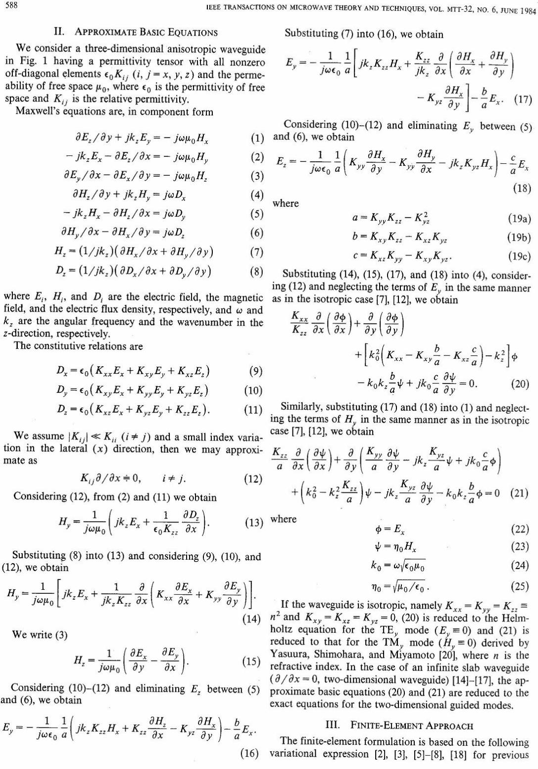
«-" y,) , Fig. 2. 2nd-order triangular element.
~ equations (20) and (21):
o
t ~ _ jk "- ($0 a", _ a"o $)) dxdy. r °a By 8y
(26)
(27)
i, Here, U is the cross section of the guide and the asterisk
I denotes complex conjugate. _ Dividing the cross section of the guide into a number of [ 2nd-order triangular elements as shown in Fig. 2, $ in (22) l and l/I in (23) within each element are defined in terms of ~~k and o/k at the nodal points k (k=1,2,-' -,6), respec! tively, as follows: ~
i (28)
(29)
~where •
(30) I ~ (" J. ~ [",,,,,,,,,,,,,,,.1' (31)
E {N } = [N,N2N3N4NjN6]T. (32)
![Here T, { . }, and { . f denote a transpose, a column vector, ~
g and a row vector, respectively, and the shape functions Nt ~to N6 are given by , i
N, ~ L,(2L, - I)
N4 = 4L,L2
(33,)
(33b)
(33c)
(33d)
N, ~ 4L,L, (33,)
N. ~ 4L,L , (331)
i With the area coordinates L 1, L 2 • and L3 [2], [5]. The ~elation equation between the area coordinates and Carte-
589
sian coordinates is given by
(34)
where (XI' YI) are the Cartesian coordinates of the vertex I (l = 1, 2, 3) of the triangle.
Both cp and t/I fields exist in the medium (or media) surrounding the optical waveguide, and these fields extend to infinity. One method for modeling the surround is imposing an artificial zero boundary condition for cp and t/I at a large enough distance from the guide. This method has as an advantage its simplicity and is widely used [2]- [8], [12], [13]. Using this zero boundary condition and substituting (28) and (29) into (27), from (26) we obtain the following global matrix equation:
[[A] [ C]
[B]][{. ) ]~ {OJ [D] (,,)
(35)
where
[AH:.J1 (Ku " a{N) a(N)T + a{N ) a{N) T {I K zz t ax ax a yay , , .
'{N)(N f )dxdY (36,)
[B] ~ ~ f 10,( kok,!: (N}(N)T
- jko-"'- {N) a(;) T)dXdY (36b) a, Y
[C] ~ ~ flo, ( ko< {N}( N) T
+jko ~: a~~} {N) T)dxdY (36c)
[D] ~ I:f {(Ku" a{N) a{N)T e In. at ax ax + K". , a(N) a{N )T
a , ay ay
+ 'k K" "[{N) a( N) T _ a(N ) (N) T] ) Z at ay ay
- [kl -k;K~:" j(N}(N )T)dxdy (36d)
Here the summation ~, extends over all different elements, the components of {cp } and {t/I} vectors are the values of Ex and TJ oHx at nodal points in 0, respectively, and {O} is a null vector.
For an anisotropic waveguide with a diagonal permittivity tensor, namely K XY = K Xl = K y: = 0, (35) is reduced to the equations derived by Koshiba, Hayata, and Suzuki [12]. In this case, [B] = (C] = (0] (where [0] is a zero matrix) and
590 ~
IEEE TRANSAcnONS ON MICROWAVE THEORY AND TECHNIQUES, VOL. MTT·32, No.6, JUNE 1984
equations I[AJ! = 0 and I[BII = 0 determine the dispersion characteristics for the E;q and Efq modes [101 in the waveguides with a diagonal permittivity tensor, respectively. The main field oomponents of the E;q modes are Ex' and Hy. while those of the EJq modes are H" and Ey (10]. The subscripts p and q are used to designate the number of maxima of the dominant field in the x- and y-directions, respectively. In the case of a two-dimensional waveguide (a/ax = 0), (35) gives the exact expression for twodimensional guided modes {lS], [19].
In order that a nontrivial solution of (35) may exist
[A] [B] [e] [D] ~O (37)
must hold. This equation is the eigenvalue (dispersion) equation which determines the dispersion characteristics for the guided modes in anisotropic waveguides having a permittivity tensor with nonzero off-diagonal elements. In the present analysis, the Cholesky method, the Householder's method, the method of bisections, and the QR method are suitably used for solving (37).
IV. COMPUTED RESULTS
Equation (12) and neglect of Ey and Hy in (20) and (21) may not be valid for the neighborhood of cutoff frequency and for the higher order modes. Therefore, it is necessary to study the accuracy of the method.
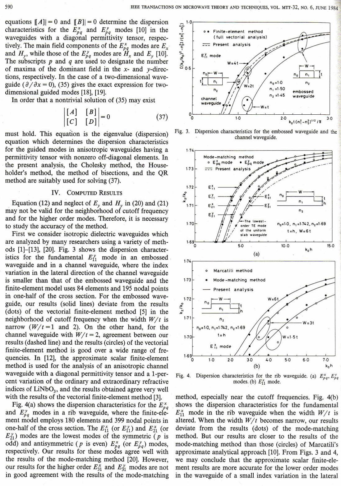
First we consider isotropic dielectric waveguides which are analyzed by many researchers using a variety of methods [1]-[13], [20]. Fig. 3 shows the dispersion characteristics for the fundamental Eft mode in an embossed waveguide and in a channel waveguide, where the index variation in the lateral direction of the channel waveguide is smaller than that of the embossed waveguide and the finite-element model uses 84 elements and 195 nodal points in one-half of the cross section. For the embossed waveguide, our results (solid lines) deviate from the results (dots) of the vectorial finite-element method [5] in the neighborhood of cutoff frequency when the width Wit is narrow (Wit = 1 and 2). On the other hand, for the channel waveguide with Wit = 2, agreement between our results (dashed line) and the results (circles) of the vectorial finite-element method is good over a wide range of frequencies. In {12], the approximate scalar finite-element method is used for the analysis of an anisotropic channel waveguide with a diagonal permittivity tensor and a I-percent variation of the ordinary and extraordinary refractive indices of LiNb03, and the results obtained agree very well with the results of the vectorial finite-element method (3].
Fig. 4(a) shows the dispersion characteristics for the E;q and EJq modes in a rib waveguide, where the finite-element model employs 180 elements and 399 nodal points in one-half of the cross section. The Ell (or Eft) and E21 (or Ell) modes are the lowest modes of the symmetric (p is odd) and antisymmetric (p is even) E;q (or EJq) modes, respectively. Our results for these modes agree well with the results of the mode-matching method [20]. However, our results for the higher order E31 and Eji modes are not in good agreement with the results of the mode-matching
" ",-------------, o ,
"< --? , " ~ £ -• • ::: 0 ·5
Fig. 1
1·71
1·10
o . Flnll._el.",.nl ",ethod (lull •• clor lal an. lysis)
P'.s.nl an.lysis
" 0_ 1.0
n, . 1·50
n, .1 · ~5 '",bossed wav.gu id.
Dispersion characteristics for the embossed waveguide and the channel waveguide.
Mod .. _",atcr.ing m .. tr.od o E:'" "'Odf • E~Q ",od.
::-:-:: Present
/~-'l, El,
I I • The '_ .. I_
I " 0"'., I! "'''''. I I ;" o. Ih. uoi'o,m
, ,;" .,,~ ..... 'JUiol.
• .-----no r- W----,
.-J q ' n'h
no.l.0 . n,.1.7~2. n,21·69
t . h. W.61
1.74',------ - ---------,
• • -" •
o Marcalili mflr.od
1·73 • Mode _",alcr. ing m.lr.od
' ·72
1·7 1
"
~.I ·O. n,,'.742. n,.1 ·69
t = h
E ~ , "'ode
Fig. 4. Dispersion characteristics for the rib waveguide. (a) E;9' E;q modes. (b) Etl mode.
method, especially near the cutoff frequencies. Fig. 4(b) shows the dispersion characteristics for the fundamental Ell mode in the rib waveguide when the width Wit is altered. When the width Wit becomes narrow, our results deviate from the results (dots) of the mode-matching method. But our results are closer to the results of the mode-matching method than those (circles) of Marcatili's approximate analytical approach [10]. From Figs. 3 and 4, we may conclude that the approximate scalar finite-element results are more acCUrate for the lower order modes in the waveguide of a small index variation in the lateral

, KOSHIB" el al.: "PPROXIM1.TE SC"LAR fINITI;.ELEMENT "N"LYSIS
• , I
i I ! , • f , I
;
I I
,
Fig. 5.
2·31
" -~
0 • ~ •
"
,. ,
Elemcnl division [or the ani.souopic dielectric rectangular wave -guide.
(.J
• Var iat ional m. O,Od
- Pr.unt lInalysis
2.31,---______ -, ,.,
-~ o • --•
"
· 2·'
.. ' Fig. 6. Dispersion characteristics for the anisotropic dielectric rectangu
lar waveguide whose optic axis lies in the xy-plane. (a) W Oo 21. (b) W " 41.
(x) direction or for those in the waveguide of a large width-to-height ratio. However, for the waveguide of a small width-to-height ratio and near the cutoff frequencies, the accuracy of the method is questionable. It seems that
5" 2.3t ,--------------- ----.
" -:; -o • -
,., , /,
2 -0 S::---~--"--"""7':"_<--.4L~__:_:c;__~~-~__= o S·O 10-0 15·0
o •
(.J '.' 2.31,--.------- -, ,.,
,. ,
, .o,~--11~fC_"!;_='-"-~~;;;'. o E{, 5·0 10·0
(bJ '.' Fig. 1. DispeI'liion characteris tics for the anisotropic dielectric rectangu
lar waveguide whose optic axis lies in the xz-plane. (a) W Oo 21. (b) W"4r.
variations in accuracy are due to the scalar apprOXImations.
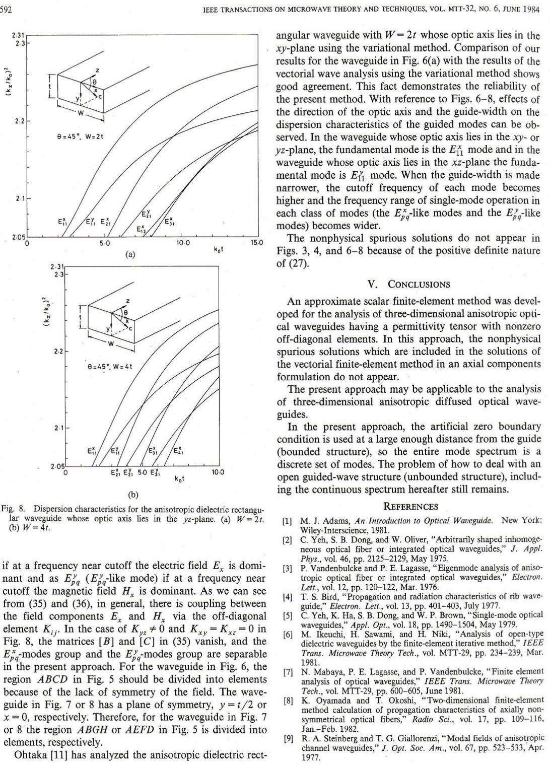
As for the second example, we consider an anisotropic dielectric rectangular waveguide composed of a uniaxial medium. A typical division of this waveguide into 2nd-order triangular elements is shown in Fig. 5, where the number of elements and of nodal points is 80 and 169, respectively. Figs. 6-8 show the dispersion characteristics for the guided modes in the anisotropic dielectric rectangular waveguides surrounded by an isotropic medium of refractive index 12.05, where the ordinary and extraordin~efractive indices of a rectangular core are /2.31 and {2.19 . respectively. The optic axis c in Figs. 6, 7, and 8 lies in the xy-plane at an angle fJ - 45 0 froin the x-axis ( K xy '" 0, K xl - Ky: - 0), in the xz·plane at an angle fJ = 45 0 from the z-axis (Kxz " 0, Kxy - Ky: " 0), and in the yz-plane at an angle fJ - 45 0 from the z·axis (Ky: '* 0, Kxy = K x: = 0), respectively. Modes are designated as E;q (E;q-like mode)
592 IEEE TRANSACTIONS ON MICROWAVE THEORY AND TECHNIQUES, VOL. MTT-J2, NO.6, JUNE 19R4
--." • •
,,,,-------------------------------------, ,.,
"
I _____ _
(,) 2.3t,-----------------------,
"
(b)
Fig. 8. Dispersion characteristics for the anisotropic dielectric rectangular waveguide whose optic axis lies in the yz-plane. (a) W - 2t. (b) W-4t.
if at a frequency near cutoff the electric field Ex is dominant and as EJ" (E/q-like mode) if at a frequency near cutoff the magnetic field Hx is dominant. As we can see from (35) and (36), in general, there is coupling between the field components E" and Hx via the off-diagonal element K i)" In the case of Kyz *- 0 and K xy = Kxz = 0 in Fig. 8, the matrices [B ] and [C] in (35) vanish, and the E;q-modes group and the E/,,-modes group are separable in the present approach, For the waveguide in Fig. 6, the region ABCD in Fig. 5 should be divided into elements because of the lack of symmetry of the field. The waveguide in Fig. 7 or 8 has a plane of symmetry, y = t /2 or x = 0, respectively. Therefore, for the waveguide in Fig. 7 or 8 the region ABGH or AEFD in Fig. 5 is divided into elements, respectively.
Ohtaka [11] has analyzed the anisotropic dielectric rect-
angular waveguide with W = 21 whose optic axis lies in the xy-plane using the variational method. Comparison of Our results for the waveguide in Fig. 6(a) with the results of the vectorial wave analysis using the variational method shows good agreement. This fact demonstrates the reliability of the present method. With reference to Figs. 6-8, effects of the direction of the optic axis and the guide-width on the dispersion characteristics of the guided modes can be observed. In the waveguide whose optic axis lies in the xy- or yz-plane, the fundamental mode is the Ell mode and in the waveguide whose optic axis lies in the xz-plane the fundamental mode is Eft mode. When the guide-width is made narrower, the cutoff frequency of each mode becomes higher and the frequency range of single-mode operation in each class of modes (the E;q-like modes and the E/q-like modes) becomes wider.
The nonphysical spurious solutions do not appear in Figs. 3, 4, and 6-8 because of the positive definite nature of (27).
V. CoNCLUSIONS
An approximate scalar finite-element method was developed for the analysis of three-dimensional anisotropic optical waveguides having a permittivity tensor with nonzero off-diagonal elements. In this approach, the nonphysical spurious solutions which are included in the solutions of the vectorial finite-element method in an axial components formulation do not appear.
The present approach may be applicable to the analysis of three-dimensional anisotropic diffused optical waveguides.
In the present approach, the artificial zero boundary condition is used at a large enough distance from the guide (bounded structure), so the entire mode spectrum is a discrete set of modes. The problem of how to deal with an open guided-wave structure (unbounded structure), including the continuous spectrum hereafter still remains.
REFERENCES
II] M. 1. Adams, An fmroouction to Optical Waveguide. New York: Wiley-Interscience, 1981.
[21 c. Yeh, S. B. Dong, and W. Oliver, "Arbitrarily shaped inhomogeneous optical fiber or integrated optical waveguides," J. Appl. PhY$., vol. 46, pp. 2125-2129, May 1915.
[3] P. Vandenbu\Cke and P. E. Lagasse, "Eigenmode analysis of aniso' tropic optical fiber or integrated optical waveguides." Electron. Lell., vol. 12, pp. 120-122. Mar. 1976.
14] T. S. Bird, "Propagation and radiation characteristics of rib waveguide," Electron. Lell., vol. 13, pp. 401 - 403, July 1977.
[51 C. Yeh, K. Ha, S. B. Dong, and W. P. Brown, "Single-mode optical waveguides," Appl. Opt., vol. 18, pp. 1490-1504, May 1919.
[6J M. Ikcuchi, H. Sawami, and H. Niki, "Analysis of open-type dielectric waveguides by the finite-element iterative method," IEEE Trans. Microwave Theory Tech., vol. MTT-29, pp. 234-239, Mar. 1981.
\11 N. Mabaya, P. E. Lagasse, and P. Vandenbulcke, "Finite element analysis of optical waveguides," IEEE Trans. Microwave TheOlY Tech., vol. MTT-29, pp. 600- 605, 1une 1981.
[8] K. Oyamada and T. Okoshi, "Two-dimensional finite·element method calculation of propagation characteristics of axially nonsymmetrical optical fibers," Radio Sci., vol. 17, pp. 109- 116, Jan.-Feb. 1982.
[9] R. A. Steinberg and T. G. GiaUorenzi, "Modal fields of anisotropic channel waveguides," J. Opl. Soc. Am., vol. 67, pp_ 523-533, Apr_ 1917.
t 1 KOSHIBA f!1 al.: APPR.OXIMATE SCALAR fINlTE-EUMENT ANALYSIS
f [lOt
! i [11]
j [12]
! [Il[
! [l4}
[l5]
[161
[!1[
t [1'[
(19}
[201
E. A. Marcatili, "Dieieetric rectangular waveguide and directional coupler for integrated optics," Bell. Sysl. Tech. J., vol. 48, pp. 2011-2102, Sept. 1%9. M. ObLaka, "Analysis of the guided modes in the anisotropic dielectric optical waveguides," Trans. but. EI«fron. Commun. Eng. Japan, v(Jll64-C, pp. 614- 681, Oct. 198\. M. Koshiba, K. Hayata, and M. Suzuki, "Approximate scalar fini te-element analysis of anisotropic optical waveguides," Electron. 1..£11., vol. 18, pp. 411-413, May 1982. M Koshiba. K. Hayata, and M. Suzuki,· On accuracy of approximate scalar finite-clement analysis o f dielectric optical waveguides." Trans. Inst. Eltctron. Commun. Eng. Japan, vol. E66, pp. 157-158, Feb. 1983. S. Yamamoto, Y. Koyamada, and T. Makimoto, "Normal-mode analysis of anisotropic and gyrotropic thin-film optical waveguides and their applications,n TrolU . b ut. E/~/rOl"l. Commrm. Eng. Japan, vol. 55-C, pp. 5~557, Oct. 1972. Y. Satomura, M. Matsuhara, and N. Kumagai, " Analysis of electromagnetic-wave modes in aniSOtropic slab waveguides," IEEE Trans. Mic,owaue Theory Tech ., vol MTT-22, pp. 86- 92, Pcb. 1974. D. Marcuse, "Modes of a symmetric slab waveguides in birefringent media-Part I: Optical axis not in plane of slab," IEEEJ. Quan/um £Irelron., vol. QE-14, pp. 736-741 , Oct. 1978. D. Marcuse and 1. P. Kaminow, " Modes of a symmetric slab optical waveguides in birefringent media, Part II: Slab with coplanar optical axis." IEEEJ. Quantwn £1«t,OII., vol. QB-I S, pp. 92-101, Feb. 1979. M. Hana and K. Kayana, "An analysis of anisotropic and inhomogeneous optical waveguide using finite clement method," Trans. Ins/. Elte/r. Eng. Japan , vo1. 101(C), pp. 213-219, Sept. 1981. M. Koshiba and M. Suzuki, "Numerical analysis of planar arbitrarily anisotropiC diffused optical waveguides usin& finit~lement method," Eltct,on. Uti. , vol. 18, pp. 579-581, June 1982. K. Yasuura, K. Shimohara, and T. Miyamoto, "Numerical analysis of a thin- film waveguide by mode-matc~ng method," J. Opf. Soc. Am., vol. 70, pp. 183-191, Feb. 1980.
•
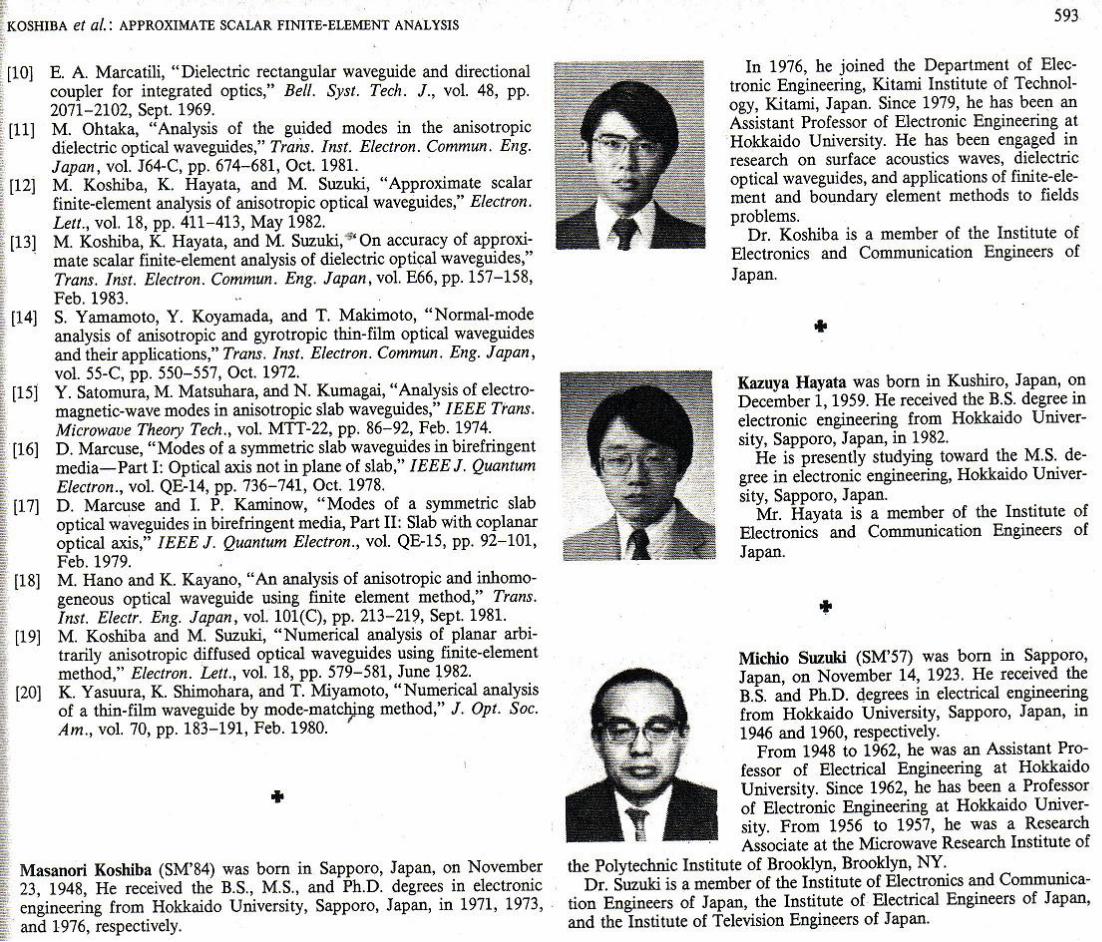
, Masanori Koshiba (SM'84) was born in Sapporo, Japan, on November 2), 1948, He received the B.S., M.s., and Ph.D. degrees in electronic engineering from Hokkaido University, Sapporo, Japan, in 1971, 1973,
• and 1976, respectively .
'" In 1976, be joined the Department of Elec
tronic Engineering, Kitami Institute of Technology, Kitami, Japan. Since 1979, he has been an Assistant Professor of Electronic Engineering at Hokkaido University. He has been engaged in research on surrace acoustics waves, dielec tric optical waveguides, and applications of fmite-dement and boundary element methods to fields problems.
Dr. Koohiba is a member of the Institute of Electronics and Communication Engineers of Japan.
• Kazuya Hayata was born in Kushiro, Japan, on December 1, 1959. He received the B.s. degree in electronic engineering from Hokkaido Universi ty, Sapporo, Japan, in 1982.
He is presently s tudying toward the M.S. degree in electronic engineering. Hokkaido University, Sapporo, Japan.
Mr. Hayata is a member of the Institute of Electronics and Communication Engineers of Japan.
+
Michlo Suzuki (SM'57) was born in Sapporo, Japan, on November 14, 1923. He reoeived the B.S. and Ph.D. degrees in electrical engineering from Hokkaido University, Sapporo, Japan, in 1946 and 1960, teSptttively.
Prom 1948 to 1962, be was an Assistant Professor of Electrical Eogineerin& at Hokkaido University. Since 1962, he has been a Professor of Electronic Engineering at Hokkaido University. From 1956 to 1957, he was a Research Associate at the Microwave Research Institute of
the Polytechnic Insti tute of Brooldyn, BrooIdyn, NY. Dr. Suzuki is a member of the Institute of Electronics and Communica
tion Engineers of Japan, the Institute of Electrical Engineers of Japan, and the Institute of Television Engineers of Japan.


![Approximate Lie Group Analysis of Finite–difference Equations · Approximate Lie Group Analysis of Finite–difference Equations A.M.Latypov ... Levi and Winternitz [8] applied](https://img.pdfslide.us/doc/110x75/5edcb4acad6a402d66677c2b/approximate-lie-group-analysis-of-finiteadiierence-equations-approximate-lie.jpg)