Embed Size (px)
Citation preview

1
330:155g Finite Element Analysis
Nageswara Rao Posinasetti
2January 16, 2008 Rao, P.N.
1. IntroductionFinite element analysis is a computer-based numerical technique that is used to solve stress analysis, heat transfer, fluid flow and other types of engineering problems.Real power is in its ability to solve problems that do not fit any standard formula.
3January 16, 2008 Rao, P.N.
Before FEA
Tested till failure before the availability of FEM.

2
4January 16, 2008 Rao, P.N.
5January 16, 2008 Rao, P.N.
6January 16, 2008 Rao, P.N.
Before FEAProblems are simplified using certain approximations before the availability of FEM.

3
7January 16, 2008 Rao, P.N.
X
8January 16, 2008 Rao, P.N.
X
9January 16, 2008 Rao, P.N.
X

4
10January 16, 2008 Rao, P.N.
X1 2 3 4 5
12
34
11January 16, 2008 Rao, P.N.
1. Introduction
It involves partitioning of a structure into a finite number of elements
Divide and ConquerElements are connected to one another at the corner points
These corner points are called nodes or nodal points
Each element is a simple geometric shapeTriangle, Quadrilateral, etc.
12January 16, 2008 Rao, P.N.

5
13January 16, 2008 Rao, P.N.
1. Introduction
In order to completely define a finite element model
Nodal pointsElementsLoadsSupports Element related data
14January 16, 2008 Rao, P.N.
1. Introduction
FEA program formulates the equations for solutions
A nodal point can have upto 6 degrees of freedom3 translational (x, y, z) and 3 rotationalAn equilibrium equation for each degree of freedom
Equations are solved for displacement at each nodal pointDisplacements are then used to evaluate the stresses
15January 16, 2008 Rao, P.N.
1. Introduction
For the model to accurately represent the physical part, the number of elements should be large.Type of element should be correctly chosenBoundary conditions should be correctly applied.

6
16January 16, 2008 Rao, P.N.
X1 2 3 4 5
12
34
17January 16, 2008 Rao, P.N.
X1 2 3 4 5 6 7 8 9 10 11 12 13 14
18January 16, 2008 Rao, P.N.
1. Introduction
Process of data preparation is tedious and long.
It is called pre-processingResults obtained are also voluminous
It is called post-processing

7
19January 16, 2008 Rao, P.N.
20January 16, 2008 Rao, P.N.
Steps in finite element analysis process
Pre-processingDefine the model
Discretize the part defining nodal points and elementsDefine element properties, material properties such as density, modulus elasticity, etc.Specify the boundary conditionsSpecify the loads
21January 16, 2008 Rao, P.N.

8
22January 16, 2008 Rao, P.N.
Preprocessor
Modelling of the geometryGenerating the finite element mesh by making a suitable approximation to the geometryCalculates the nodes and elemental propertiesAllows for the specification of the support condition and loading conditions for the individual element positions.Allows the material properties to be specified.
23January 16, 2008 Rao, P.N.
24January 16, 2008 Rao, P.N.

9
25January 16, 2008 Rao, P.N.
26January 16, 2008 Rao, P.N.
27January 16, 2008 Rao, P.N.
10
28January 16, 2008 Rao, P.N.
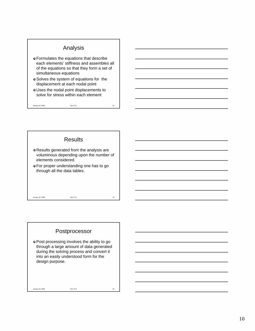
Analysis
Formulates the equations that describe each elements’ stiffness and assembles all of the equations so that they form a set of simultaneous equationsSolves the system of equations for the displacement at each nodal pointUses the nodal point displacements to solve for stress within each element
29January 16, 2008 Rao, P.N.
Results
Results generated from the analysis are voluminous depending upon the number of elements considered.For proper understanding one has to go through all the data tables.
30January 16, 2008 Rao, P.N.
Postprocessor
Post processing involves the ability to go through a large amount of data generated during the solving process and convert it into an easily understood form for the design purpose.

11
31January 16, 2008 Rao, P.N.
32January 16, 2008 Rao, P.N.
33January 16, 2008 Rao, P.N.
12
34January 16, 2008 Rao, P.N.
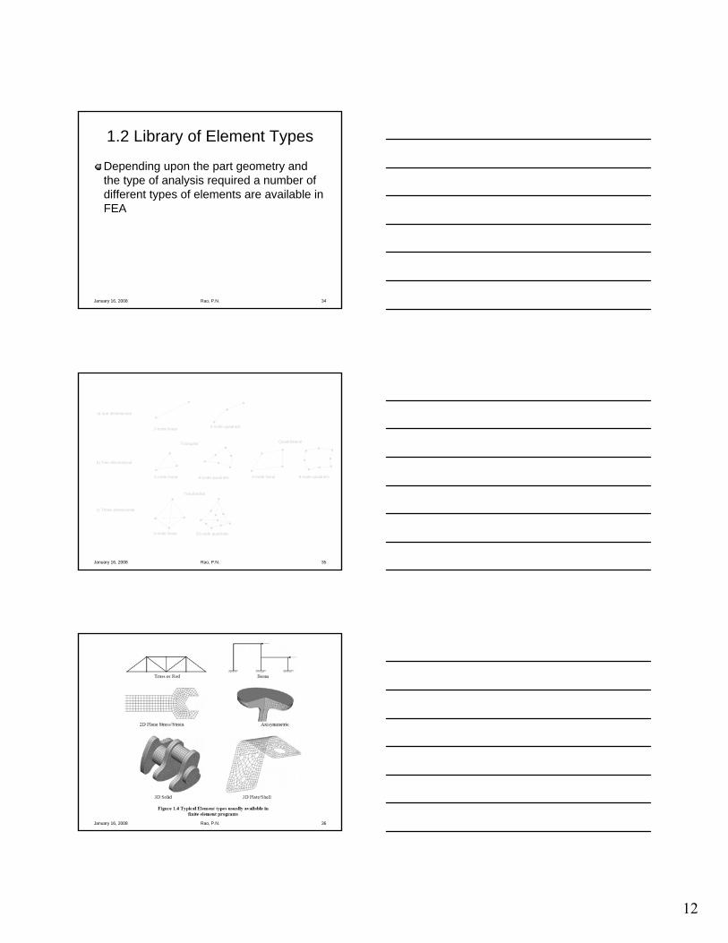
1.2 Library of Element Types
Depending upon the part geometry and the type of analysis required a number of different types of elements are available in FEA
35January 16, 2008 Rao, P.N.
2-node linear 3-node quadratic
3-node linear 6-node quadratic 4-node linear 8-node quadratic
4-node linear 10-node quadratic
a) one dimensional
b) Two dimensional
c) Three dimensional
Triangular Quadrilateral
Tetrahedral
36January 16, 2008 Rao, P.N.

13
37January 16, 2008 Rao, P.N.
1.3 Advantages of using FEA
Irregular shaped partsParts made from different materialsIrregularly placed loadsLarge number of supportsProvides results throughout the part (all points)Easy to change the model
38January 16, 2008 Rao, P.N.
Why Use FEA?Provides a non-destructive means of testing products.Faster prototyping for “what if” scenarios.Design optimization.Speed up time to market by shortening the design cycle.
Courtesy Algor Inc, Pittsburgh
39January 16, 2008 Rao, P.N.

14
40January 16, 2008 Rao, P.N.
Best Practices
FEA requires engineering judgment. In the best case, you should know the approximate answer before you begin.
Proper selection of elements, materials, loads, constraints and analysis parameters comes from experience.
Courtesy Algor Inc, Pittsburgh
41January 16, 2008 Rao, P.N.
Best Practices
Understand that the computer model never matches reality (it’s only an approximation).The surest route to failure in FEA is to underestimate the complexity of the technology.
Courtesy Algor Inc, Pittsburgh
42January 16, 2008 Rao, P.N.
Aerospace IndustryOrbital Technologies Corporation
The above illustration shows how engineers analyzed a Biomass Production System to conduct biotechnology plant research.
FEA in Different Industries
Courtesy Algor Inc, Pittsburgh

15
43January 16, 2008 Rao, P.N.
FEA in Different Industries
Automotive IndustryDanly Engineering Services, Division of EnprotechMechanical Services, Inc.
The above illustration shows how engineers analyzed a power press with additional cutouts. Courtesy Algor Inc,
Pittsburgh
44January 16, 2008 Rao, P.N.
FEA in Different Industries
Biomedical IndustryOphthalmic Consultants of Boston and the Tufts University School of Medicine
The above illustration shows stresses on an eye as it underwent a 30° saccadic eye movement. This was modeled to help understand why retinal detachments occur.
Courtesy Algor Inc, Pittsburgh
45January 16, 2008 Rao, P.N.
FEA in Different Industries
Power/Utility IndustryCronulla Sewage Treatment Plant
The above illustration shows how engineers modeled a piping system to verify that the number of bellows could safely be reduced by using lightweight, spiral-wound stainless steel. This allowed them to keep a $90 million sewage treatment plant upgrade on budget.
Courtesy Algor Inc, Pittsburgh

16
46January 16, 2008 Rao, P.N.
1.4 Historical Development
Concept first appeared in 1956Name “Finite Element” is used in 1960 by Clough1970’s large programs running in mainframe computers1980’s moved to personal computers and widespread use
47January 16, 2008 Rao, P.N.
CAD to FEA
There are many approaches for integrating CAD systems to FEA
48January 16, 2008 Rao, P.N.
CAD System
Geometricmodeller
Pre-Processor
CADGeometry
FE Mesh
FullFEM model
FEAnalysis
FE Pre-Processor
FE PostProcessor
Inventor to Algor

17
49January 16, 2008 Rao, P.N.
Geometricmodeller
FEAnalysis
FE Pre-Processor
FE PostProcessor
Integrated FEA System, e.g. Algor
50January 16, 2008 Rao, P.N.
Design problemSelect a round bar to be constructed from an AISI 1020 cold-drawn steel to support the 300-pound ball. Assume a safety factor of 2, and determine the deflection for the size selectedYield stress = 61,000 psi
51January 16, 2008 Rao, P.N.
Design problemCantilever beamMax bending moment = 300 x 36
= 10,800 in-lbStress in the beam, S = M/ZS = 10,800 x 32 / (Π d3)Allowable stress = 61,000 / 2 = 30,500 psiEquating the above two, and solvingd = 1.533 in = 1.625 in (preferred size)Deflection = -FL3 / (3EI) = 0.455 in

18
52January 16, 2008 Rao, P.N.
Problem using FEA
Start with 2 in dia; Max stress = 13,751 lower than the allowable 30,500 psi
53January 16, 2008 Rao, P.N.
Problem using FEA (contd..)
Next try 1.5 in dia; Max stress = 32,599 higher than the allowable 30,500 psi
54January 16, 2008 Rao, P.N.
Problem using FEA (contd..)
Next try 1.625 in dia; Max stress = 25,635 lower than the allowable 30,500 psi - Acceptable

19
55January 16, 2008 Rao, P.N.
Problem using FEA (contd..)
For 1.625 in dia; Max displacement = 0.47 in Compare this to analytical solution of 0.455 in, a 3% error
56January 16, 2008 Rao, P.N.
Analytical Problem Solving Process
Establish clearly defined goalCompile and qualify the inputsSolve the problem with the most appropriate meansVerify and document the results
57January 16, 2008 Rao, P.N.
What is the goal of the Analysis?
The decisions to be madeHow important is the exact solution to the problem?
This will help in identifying the precision of the inputs to the problem.
What information from the analysis will help in taking the engineering decision
When can you stop analyzing?Which shortcuts are allowed?

20
58January 16, 2008 Rao, P.N.
Common MisconceptionsMeshing is everything
Current preprocessor are efficient and generally give good meshes. But that is not the end since it is only an input.Boundary conditions and forces are added by the user. The accuracy of the results depend to a great extent on them.
FEA replaces testingDepends on the confidence in the analytical methods used.There is no guarantee that the results are accurate.
59January 16, 2008 Rao, P.N.
Common Misconceptions
Finite element analysis is easyDon’t underestimate the complexity of the problem.Don’t jump to conclusions too quickly.Some little experiments may be required to gauge the forces and reactions in the part.Interpreting the results is also an important task.
60January 16, 2008 Rao, P.N.
Common Misconceptions
Finite element analysis is hardIt is estimated that 20% creativity and 80% hard work and patience.Learned through more practice
Learning the interface equals learning FEA

21
Questions or Comments?
62January 16, 2008 Rao, P.N.
ExercisesDefine the terms: nodal point, element and degree of freedomWhat does the term discretization mean in the finite element method?List three different material properties that must be defined for each of the element.Explain why the computer is necessary in the use of the finite element method.Explain why computer graphic techniques are used during the postprocessing phase of a finite element analysis. What is the alternative to using these graphical displays?What advantage would a company derive by performing a finite element analysis of an existing part, which can be strain gauged and tested in a lab?