Embed Size (px)
Citation preview
COPY4.
L
● ✎ ✎I 1/
:O. ● ●’0 : ● 0,.’
.
●o* . ,,/ -.-!._
:-:--$-;--;:: : . .“ ● T
~~mJw~f”#-.-m** 9:0 -* B*- e** .0. . . . . .4
● .:o:: . ::c: ● .eee:
● ● 0* :● ● e
9** :.. . .
LA-2052c._ JJ_● :. ---~=.--= - =-———.—
Copy No. “>_—_-=!-.-. /..,.,:. .. ,. ..... .
AEC.,. ,
RESEARCHANDDEVELOPMENTREPORT
LOS ALAMOS SCIENTIFIC LABORATORY(WTHEUNIVERSITYOF CALIFORNIAo LOSALAMOS NEW MEXICO
_____— ..— —____ —.—- ‘-----r”v- i‘ ‘“VERIFIED UNCLASI;IED
ZF5
E--
R179 ~ -_*-=.= .-._— —.. ———-,—
NONWEAPONS ACTIVITIES AT LOS ALAMOS SCIENTIFIC LABORATORY
Part III
Power Reactor Experiments—— ——
.-.- .Q_. ––—-— — ~-. . -
___ __—= .——-–=–— —-.
~~_-. .-. — ––. - ..— —Th
. ... ...),., ,
,.,
—
This document mnt. . .
1954. Its trans-mittal or the son is prohibited.
● 00: :6: :● =*.
●
● 0.*● *● *.0● e
i ● e--.00 :
●●
u. . ,T.zq ..,+. -
•.~● 99
● 0 ●9**
● ● 0: ●ma ●
. . . ● ●● * FIED
APPROVED FOR PUBLIC RELEASE
APPROVED FOR PUBLIC RELEASE

● m ● .m.. 9*9 ● boo ● ●°:
● ● 0:: ● .**● ● 00
.***
..*9 ● ●.O ..: .o@q● . . ● ea
. . .00 ● 09 ●O: ●:. .*e9=9: .*9*● a*: e*. ●● 0● 8 ● : .:O SO*
. . ●0: ● m-
LEGAL NOTICE
This report was prepared as an account of Govern-ment sponsored work. Neither the United States, nor theCommission, nor any person acting on behalf of the Com-mission:
A. Makes any warranty or representation, expressor implied, with respect to the accuracy, completeness,or usefulness of the information contained in this report,or that the use of any information, apparatus, method, orprocess disclosed in this report may not infringe privatelyowned rights; or
B. Assumes any liabilities with respect to the useof, or for damages resulting from the use of any infor-m ation, apparatus, method, or process disclosed in thisreport.
As used in the above, “person acting on behalf of theCommission” includes any employee or contractor of theCommission to the extent that such employee or contrac-tor prepares, handles or distributes, or provides accessto, any information pursuant to his employment or con-tract with the Commission.
Printed in USA. Charge 45 cents. Available from theU. S. Atomic Energy Commission, Technical InformationService Extension, P. O. Box 1001, Oak Ridge, Tennessee.Please direct to the same address inquiries covering theprocurement of other classified AEC reports.
.0: . . . . . .● ● : ●:= .*C
● 9● 0.:: ●: ●
● . . :.● 9 ● *e ●:b ●9: ●:. ..●
.●..”.:O””& ● m*●*. . .●
● 0.● ** ● ●°:
●b ● e*
● ::: ● m..● o:
● 0 . . . ..: ●o:
APPROVED FOR PUBLIC RELEASE
APPROVED FOR PUBLIC RELEASE

.—
— —
●☛✎✎☛☛:Oo_O_—. .____x3-00.5:_*T: G:_ :—.—..
● O ● eo ● ** . . . ● **● ● : :0 : :.
9**● :● ●:0 : ● :
● 0. .**
● m●
●.
““i‘NCLASSIF● O
::
::
LA-2052REACTORS - RESEARCH AND TESTING(Distributed according to M-3679,18th edition)
This document consists of 44 pages.
LOS ALAMOS SCIENTIFIC LABORATORYOF THEUNIVERSITYOF CALIFORNIA LOS ALAMOS NEW MEXICO
REPORT WRITTEN June 1956
SERIES A
SERIES B
DISTRIBUTED: November 1956
DISTRIBUTED:
ml 7 p57
NONWEAPONS ACTIVITIES AT
LOS ALAMOS SCIENTIFIC LABORATORY
Part III
Power Reactor Experiments
by
Samuel Glasstone
Contract W-7405 -ENG. 36 with the U. S. Atomic Energy Commission
UNCLASSIFIED
Tm
● ** ●
●“eo *:* ::● ** :Or● 0:0
● : ,/: :
,, ●:0 ● ** ● e@ :*O ● -UNCLASSIFIED
● O● *● 0● ***e ,{,9* ● 00. . ● m= . ●
APPROVED FOR PUBLIC RELEASE
APPROVED FOR PUBLIC RELEASE

● O
. . ●9: ● .*9 ,** w.● ● *●: : .0
;; 0::.be ● .=. e*
● . ●*: ● *O 9 ● 00
UNCLASSIFIED
mJ$si[\ED?
.
● e ● *. . . .
::4$;<● *O
● ::●● 0: ● 090
● e.e. ● 0.900 ● *
APPROVED FOR PUBLIC RELEASE
APPROVED FOR PUBLIC RELEASE

FOREWORD
In the early part of 1954, there were issued two reports (LA-1632
and 1633) summarizing the weapons activities at US Alamos Scientific
Laboratory. These reports were intended primarily for the inform ation of
new staff members of the Laboratory and for interested representatives of
the Armed Forces and the Atomic Energy Commission. During the past
two or three years, the work of the Laboratory has greatly expanded into
applications of nuclear energy which are significant for national defense and
security, but are not directly connected with weapons development. It was
felt, therefore, that a description of the nonweapons activities of the Lab-
oratory would serve a useful purpose at this time.
For classification reasons, it has been necessary to issue the report
in three parts; the first is concerned with controlled thermonuclear reac -
tions, the second with nuclear propulsion, and the third with power reactor
experiments. As with the reports on weapons activities, the present re -
ports are not intended to discuss the various topics in great detail, but
rather to describe the underlying principles. Their basic purpose is to
present a general background of the subject and to indicate the lines along
which work is in progress in the Laboratory. It is in the hope that the mate-
rial contained in them will prove useful to new staff members and to others
concerned with the activities of the Laboratory that these reports have been
prepared.
Norris E. BradburyDirector
● *9 ● ● ** ● ** ● .●“O::: :3::● ● *● 0:.:: ● . .
●
● 0 ●:* ● ** ● ** ● ** ● *
● *● b● 000.. .**.,@ ●.0 ● 9*.● * .99 ● . ● e
APPROVED FOR PUBLIC RELEASE
APPROVED FOR PUBLIC RELEASE

● ☛ ● ● ☛ ● ☛☛
.00 ● ** ● U“:● ● * *
s ● 0+● *O
● 9
. . ● oe ●:0 ●0: 8:0 ●*m● ** ●*O-*9 .::.* .● 0● 0 ● : ●:* ●a..* ●0: ● a*
UNCLWSiFi~
ACKNOWLEDGMENT
I wish to take this occasion to express my sincere thanks to the many
members of the Laboratory who helped, in one way or another. in the prep-
aration of this report. Their generous and wholehearted cooperation not
only greatly simplified my task, but made it a pleasure and a privilege. I
would also like to thank the Director of the Laboratory and his staff for
giving me the unique opportunity to write this series of reports, and for
providing the facilities which made the work possible.
Samuel Glasstone
● m ● 00 ● 0.
*:;
● :: ● *:● 0... ● *.
99* . .
\
APPROVED FOR PUBLIC RELEASE
APPROVED FOR PUBLIC RELEASE

●“0 ● .. . . ● m●°0 .●:*: ●
● 000● **
● 0-;● :0..
● ☛☛ .0●●0::● ● *● 9*● 00 .*
Introduction
The first homogeneous reactor, employing an aqueous solution of an enriched uranium
salt as the fuel (Water Boiler), and the first fast-neutron reactor d’Clementine”), which was
also the first reactor to use plutonium as the fissionable material, were developed and built
in the Laboratory. These reactors were intended primarily as neutron sources for experi-
mental purposes. Although they did produce substantial amounts of heat, they were not designed
to yield useful power. However, when the activities of the Laboratory expanded into the field
of power reactors, it was natural that special interest should be attached to systems of the
same basic type as those with which previous experience had been gained, namely, homogeneous
(thermal neutron) reactors and plutonium (fast neutron) reactors.
Homogeneous Reactor Systems
Advantages and Disadvantages
Reactors using a homogeneous aqueous solution as the fuel have a number of stgntficant
advantages over those having solid fuel elements. First, the problem of processing the spent
fuel to remove fission products is greatly simplified. The need for fabricating fuel elements,
which must be dissolved ‘for processing and then refabricated, is avoided. Second, aqueous
reactor fuel solutions generally have fairly large negative temperature coefficients, due chief ly
to the expansion (and decrease in density) that accompanies an increase of temperature. As a
result, homogeneous reactors of this type are both stable and easily controlled. In fact, as
will be seen later, such reactors can be designed to operate essentially without controls, ex-
cept durtng start up. When it is operating at the design temperature, the external demand on
the reactor automatically adjusts its power output.
The most serious drawback of the homogeneous power reactor using aqueous uranium fuel
solutions is their highly corrosive nature, especially at the high temperatures necessary to
produce useful power. In the conventional homogeneous reactor design, such as the HRE and
HRT at Oak Ridge, the fuel solution is pumped from the reactor core, through a heat exchanger,
and back to the reactor. Steps must therefore be taken to prevent corrosion of pumps, piping,
and heat exchanger, as well as of the reactor vessel itself. In the homogeneous reactors to
be described below, however, this difficulty does not arise, since the fuel solution is not circu-
lated through an external heat exchanger.
APPROVED FOR PUBLIC RELEASE
APPROVED FOR PUBLIC RELEASE

!!!-i.kiijdlikii:
The production of hydrogen and oxygen due to the decomposition of water by radiation–
neutrons, and gamma rays, and especially, fission fragments–constitutes a further disadvantage
of the homogeneous aqueous reactor system. If there were no recombination of these gases,
very high pressures would develop, but conditions have been found under which considerable
hydrogen-oxygen recombination can occur. Consequently, the radiolytic decomposition of water
is not to be regarded as a serious problem.
Aqueous Fuel Solutions
In order to operate at high thermal efficiency, a power reactor must produce steam (or
other working fluid) at high temperature. In most circumstances, the maximum temperature
for a reactor with an aqueous fuel solution is the critical temperature of water, i. e., 3’74°C
(705°F). Solutions of simple uranium salts, however, suffer from another limitation which
serves to lower still further the maximum ~perating temperature.
Two salts of uranium which are sufficiently soluble in water to provide a reactor fuel
solution, and which are reasonably stable at high temperatures and under the influence of
radiation, are uranyl sulfate and uranyl fluoride. But solutions of these salts have the some-
what unusual property of changing from a single liquid phase to a two-liquid phase system at
temperatures above 285°C (545°F) for the sulfate and 310°C (590°F) for the fluoride. One
phase then consists mainly of the uranium compound with a small proportion of water, whereas
the other is mostly water with a small amount of the uranium salt. Operation of a reactor would
have to be restricted to temperatures below that at which the phase transition occurs, since a
fuel system consisting of two liquids of such different compositions might lead to instability.
Furthermore, the uranium-rich phase is extremely corrosive and would be difficult to contatn.
It is known that the addition of excess acid to the uranyl solutions, i. e. , sulfuric acid to
the sulfate or hydrofluoric acid to the fluoride, raises the temperature at which the phase
transition occurs. But at temperatures that would be sufficiently high to make the use of such
solutions worth while, considerable decomposition would occur accompanied by volatilization of
such noxious gases as sulfur dioxide and trioxide or hydrogen fluoride. The solutions would
also be extremely corrosive.
Interest in the Laboratory has centered about the possible use of uranium-phosphoric acid
solutions as the fuel for homogeneous reactors. Although uranium phosphates are not very
soluble tn water, both the oxides U02 and U03 are sufficiently soluble in excess phosphoric
acid, in which complex uranous and uranyl phosphates are formed. Phosphoric acid solutions
are stable at high temperatures and, apart from the radiolytic decomposition of the water, are
expected to be essentially unaffected by radiation. The uranium-phosphoric acid solutions do
not exhibit the transition from one the only significant upper
I
APPROVED FOR PUBLIC RELEASE
APPROVED FOR PUBLIC RELEASE

@MP!!?● . ..
● ●*:0 ●0:::● :000: ::● * ● *9 . .
UNCLASSIFIEDtemperature limit is the critical temperature at which the liquid phase ceases to exist. How-
ever, the presence of excess phosphoric acid raises the critical temperature of the solution
considerably above that of water. For example, in 7.5 M phosphoric acid, the liquid meniscus
disappears at a temperature of about 525°C (980°F), which is considerably higher than would
be required in the operation of a reactor using an aqueous fuel solution.
Another point about phosphoric acid solutions that is worth mentioning is their value as
moderators for thermal reactors. At high temperatures, such as are of interest for power
reactor operation, the density of hydrogen nuclei in these solutions is considerably greater
than in water at the same temperature and pressure. Thus, under these conditions, phosphoric
acid is the better moderator, especially as the capture cross section of phosphorus for thermal
neutrons is comparatively small.
It is seen that uranium-phosphoric acid solutions offer interesting possibilities for use as
the fuel tn homogeneous reactors. The appreciable expansion resulting from an increase of
temperature contributes to the negative temperature coefficient, making self-control a definite
possibility. The small capture cross section of phosphorus for thermal neutrons (0.2 barn),
compared with sulfur (0.45 barn), is an added advantage. The only important drawback is the
corrosive nature of the cone entrated phosphoric acid solutions at high temperatures. It is felt,
however, that this can be overcome by means of gold or platinum plating or cladding over
stainless steel.
For various reasons, it seems unlikely that homogeneous reactors employing uranium-
phosphoric acid fuel solutions will be used for large central-station power supply. There are,
nevertheless, special circumstances in which power reactors of moderate size, e. g. , 10 Mw,
would be particularly useful, e. g., for remote locations or as portable power sources for
military or emergency applications. For such purposes, the reactor should have the minimum
number of moving parts, it should be compact, and require little or no attention during operation.
It is these basic considerations which have largely determined the design of the power reactor
experiments in the Laboratory.
Properties of Uranium-Phosphoric Acid Solutions
Before proceeding to describe these experiments in some detail, it will be helpful to
examine some of the properties of uranium-phosphoric acid solutions that have a direct bearing
on their use as the fuel medium in homogeneous reactors. Utilizing phosphoric acid of suffi-
ciently high concentrations, it is possible to tisolve enough U02 or U03 to provide a fuel
solution that will make a critical reactor having a reasonable volume. The compositions of the
two solutions selected for the power reactor experiments in the Laboratory are approximately
as follows:
a!!uk.9 *:....** ● ..** ..*
. ...*:* ● ● .-a
:* :....● e
APPROVED FOR PUBLIC RELEASE
APPROVED FOR PUBLIC RELEASE

● e ● : .*O ..: .*:
~~~~.. 90, gee ● 00 ●:* ● -
● **: ●
● 8** .:00● O* ● *● m : :**O
.9 ●0: ● *
I 0.5 M U03 in 7.5 M H3P04 ( - 50 per cent)
II 0.3 M U02 in 17 M H3P04 ( - 95 per cent)
It will be noted that the uranous, i. e. , U02 or U(IV), solution II has a higher phosphoric acid
concentration than the uranyl, i. e., U03 or U(VI), solution I. This is because U02 is less
soluble than U03 for a given concentration of the acid. However, there are certain benefits to
be gained from the use of solution II. as will be evident in due course.
Thermal Expansion
The thermal expansion of uranium-phosphoric acid solutions has been studied by sealing
the liquid into thick-walled quartz capillary tubes and observing the position of the meniscus
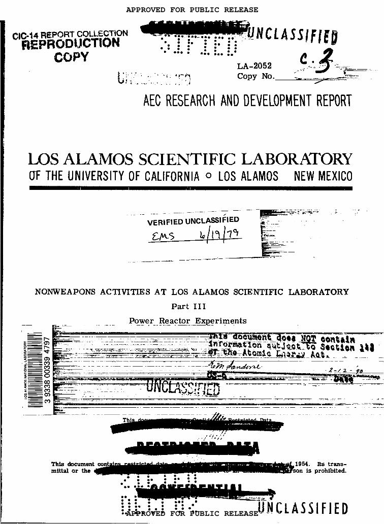
as the temperature was raised. Some of the results obtained are shown in Fig. 1. Curves
A, B, and C are for approximately 0.5 M U03 in 7.5 M H3P04, which is solution I referred
to above. The results show the percentage of the total volume of the tube occupied by the
liquid at various temperatures for different initial fillings. The slope of the curve is a measure
of the thermal expansion, the steeper the curve the greater the expansion coefficient.
For an initial filling of about 59 percent (curve B), there is a sharp decrease in volume
at about 420°C, and shortly thereafter the meniscus disappears. The temperature is then the
critical (phase) temperature for the system. There might possibly be some advantage tn
operating a reactor near the dip in the curve. Then if the temperature became too high, the
meniscus would disappear, the volume occupied by the fuel wouId be suddenly increased, with
the result that the reactor would become subcritical and automatically shut itself down. There
is some feeling, however, that the system may have some elements of instability near the phase
critical temperature, and so this region is being avoided.
If the initial filling, at room temperature, is about 62 per cent or more (curve C), the
tube becomes filled before the phase critical temperature of the system is reached. As is to
be expected, the greater the initial volume, the lower the temperature at which the liquid fills
the tube. If the temperature is raised still higher, it is expected thai the container will be
stressed to a considerable extent owing to the relatively small compressibility of the phosphoric
acid solutions.
Increasing the phosphoric acid concentration is associated with two general effects, as
seen from curve D (Fig. 1) for a 0.5 M U03 in 12.7 M H3P04 solution. First, the curve is
flatter than those for the less concentrated acid solutions, indicating a smaller thermal expansion
and, probably, a smaller negative temperature coefficient of the reactor using such solutions.
Second, the disappearance of the meniscus or the complete filling of the tube by liquid, depending
APPROVED FOR PUBLIC RELEASE
APPROVED FOR PUBLIC RELEASE
Ioc
90
80
70
60
50
40
4diiiii$~~;●*●:9 :00 ● O9 ● 9* . .
● ● *b.::*● *. ::
● :*. : :::0 ● oe ● 0
WWJXHECI...
I I I I I I
—
0
100 200 300 400 500 600 700
TEMPERATURE (“C)
APPROVED FOR PUBLIC RELEASE
APPROVED FOR PUBLIC RELEASE

. . -.** z 9-*9 ● 9
● 900●ae ● ●.0
. . 900 ● ** 99* ●:0 ● *9** ●
● 9** : .:06● Oo e:: :09.Ob.0 ● e* ● *
cm the extent of initial filling, neither of which is shown in the figure, occurs at higher tem-
peratures. This means that an increase in the phosphoric acid concentration of the fuel solution
makes possible higher operating temperatures of the reactor. More important, however, is the
decrease in the vapor pressure, which is discussed below.
The foregoing results were obtained with U03 solutions, but since the properties are
determined mainly by the phosphoric acid, similar phenomena occur with solutions of U02 in
this acid. Because the phosphoric acid concentrations of interest in the latter case are much
higher than those used for U03, the phase critical temperature has not been observed. It is
known to be above 600°C (1, 100°F) for systems consisting of approximately 0.4 M U02 in 14
(or more) M H3P04. Thus high reactor temperatures are possible, in principle, with such
solutions.
Va~or Pressure
The (aqueous) vapor pressure of the solutions decrease, as expected, with increasing
phosphoric acid concentration. The addition of uranium apparently causes some increase in
the vapor pressure, but this is not very significant from the present standpoint. The observed
gage pressures, in lb/in. 2 (psi), over four phosphoric acid solutions, each about 0.5 M in
uranium, at temperatures above 300°C (580°F) are shown in Fig. 2. The vapor pressure curve
for water, which ends at the critical point, is given for purposes of comparison.
Increase in the phosphoric acid concentration, especially in the higher range, produces a
marked decrease in the vapor pressure at any given temperature. This is not surprising when
it is realized that the concentrated solutions contain very little water. In fact the 18.4 M
solution is actually 100.7 per cent H3P04, that is, it consists of pure H3P04 plus excess P205.
The vapor pressure observed at high temperatures is presumably a dissociation pressure of
H3P04 rather than a true vapor pressure of water. By increasing the P205 content to an even
greater extent, thus moving into the region of pyrophosphoric acid (H4P207) or metaphosphoric
acid (HP03), the “vapor” pressures can be reduced to values of the order of 1 atm. The
possibility of making such media the basis for reactor fuel solutions is being studied.
In the Los Alamos power reactor experiments, there are no plans for the inclusion of
interml thermal shields, such as are introduced in some other reactors to decrease the heating
of the walls of pressure vessels caused by neutrons and gamma rays. From this point of
view it is advantageous, therefore, to use concentrated phosphoric acid fuel solutions of low
vapor pressure. With these solutions, relatively thin-walled vessels can be employed, so that
the wall-heating problem, and also the cost, are greatly reduced.
ilu@lii●.:●
..O : : : ::::0. ●**.
● .● ● **
●*. ●*
APPROVED FOR PUBLIC RELEASE
APPROVED FOR PUBLIC RELEASE

3,000
2,000
I,ooc
o300 400 500 600
TEMPERATURE (“C)
e!?●
● *::0 ●0::● a :● :...: ::
● ● om . .
I ICRITICALy~
I
POINT
1’/
/
/’
WATER /’
/
//
I
/’
APPROVED FOR PUBLIC RELEASE
APPROVED FOR PUBLIC RELEASE

Thermal Stability
● 0 .OOO:O O.: ::
‘:”%’Ji&IA..9*9 ● 08 ● 00 ●:0 •~● *- ●
● 9.* : .:0-● 00::: :0be
.0 ●0: ●
-. .--.”
If a solution of U03 in concentrated phosphoric acid is heated, oxygen is evolved at an
appreciable rate at temperatures above 200°C, the U(VI) being converted into the U(W) state.
The decomposition occurs the more rapidly the higher the concentration of phosphoric acid, It
can be prevented, however, by having an excess pressure of oxygen in the vessel containing
the solution. For example, when the oxygen pressure, at room temperature, over a 0.6 M U03
tn 7.5 M H3P04 solution was 200 psi, no decomposition was detected during several hundred
hours at 430°C (805°F).
The fact that solutions of U(W) in concentrated phosphoric acid decompose spontaneously
to yield U(IV) testifies to the great thermodynamic stability of phosphoric acid solutions of U02.
No thermal decomposition of such solutions is therefore to be expected, especially if a reducing
or inert atmosphere is maintained over them.
Radiolytic Decomposition
Like all aqueous solutions, those containing phosphoric acid undergo a certain amount of
radiolytic decomposition, the water being dissociated into hydrogen and oxygen gases. However,
the dissolved uranium, particularly in the U(IV) state, is able to catalyze the recombination
reaction to the extent that a relatively low equilibrium pressure is attained under conditions
of interest for reactor operation.
In U(IV) fuel systems, such as solution II mentioned above, i.e., 0.3 M U02 in 17 M
H3P04, it is estimated that the equilibrium pressure of the radiolytic hydrogen-oxygen gas
mixture at 430°C and a thermal flux of 1013
neutrons/ (cm2)(sec) would be about 20 psi. In the
U(VI) solution I, however, which contains 0.5 M U03 in 7.5 M H3P04, the equilibriu~ pressure
would be considerably higher under the same conditions, possibly several hundred pounds per
square inch. Nevertheless, pressures of this magnitude would not be very objectionable in
reactor operation. The aqueous vapor pressure of solution I at 430°C is about 3,600 psi, and
so an increase of total pressure to 4, 000 psi would not be serious in the circumstances. If,
for any reason, it is desired to decrease the pressure due to the radiolytic gases, this can be
achieved by the addition of a small amount of a cupric salt to the solution, sine e the
is known to be an excellent recombination catalyst.
Corrosion
As stated earlier, concentrated solutions of phosphoric acid are very corrosive,
Cu++ ion
especially
at elevated temperatures. At 50°C or below, Type 347 stainless steel, which is widely used in
chemical industry for corrosive liquids. is hardly attacked by even the more concentrated
phosphoric acid solutions. But if the temperature is increased, corrosion of the steel increases
UNC1>PSSIF!ED:“:-””* “: ●
dl@hi&i● ●
●e. : : : ::::@. ● *me
● e●
● 0.● *. ● a
APPROVED FOR PUBLIC RELEASE
APPROVED FOR PUBLIC RELEASE

● m ● 00● *e. O.:● .
.** .● O.**-*. *-.● O*.... .-*
● ● eo ● *a ●● ● **
● :** . . . ::● 99*..● :.... . .
stgntficantly. Above about 200°C, the corrosion rate commences to decrease, passes through
a minimum, and then increases steadily as the temperature is raised. The increase in cor-
rosion rate up to 200°C is attributed to the increased rate of dissolution by the phosphoric
acid of the protective oxide film on the steel. Above this temperature an adherent phosphate
film is formed that impedes corrosion, but at still higher temperature this film also dissolves
exposing the metal to attack.
It appears certain from the observations made that no commercial stainless steel or other
iron or nickel alloy can be used, without further protection, for phosphoric acid at temperatures
of interest for power reactor operation. The solution to the problem of containing the fuel
seems to lie in the use of steel vessels coated with either gold or platinum in those parts
where high temperatures will be encountered. These precious metals are not appreciably
attacked by any uranium-phosphoric acid solutions at 43 O°C. The same is true for various
alloys of platinum with gold, iridium, rhodium, or ruthenium. At lower temperatures, however,
e. g., 300 to 350°C, the more concentrated phosphoric acid solution II might be contained tn
silver.
Corrosion Protection ‘“
In the Laboratory, gold plate (or claddlng) is being used to protect the steel from corro-
sion. To be effective, the plate must have no pinholes. The presence of such pinholes can be
detected by immersing the plated object in an acidified 1 per cent potassium ferricyanide
solution and maktng it the anode, with a platinum cathode, in an electrolysis lasting 10 to 30
sec. Ferrous ions, formed at the base of any pores (or pinholes) in the plating, produce an
insoluble blue compound with the ferricyanide. Subsequent washing, to remove acid, does not
remove the biue compound, so that the location of any defects can then be determined by
visual inspection.
The use of gold coating in a reactor vessel raises an interesting point. The capture of
neutrons by gold, followed by a stage of beta decay, results in the formation of mercury. Since
mercury-gold alloys have considerably lower melting points than pure gold, it was thought that
the temperature of operation of the reactor might be limited by the melting of the protective
coatings of gold. Experiments with gold amalgams, containing as little as 1 or 2 per cent of
mercury, have shown that even in these dilute alloys, mercury has a relatively high vapor
pressure at 430°C and distils out. In one of the reactor designs (LAPRE II), plans are, in fact,
being made to pump off the mercury vapor from behind the gold cladding through small holes
piercing the vessel wall.
APPROVED FOR PUBLIC RELEASE
APPROVED FOR PUBLIC RELEASE

● e ● ● ● *. ● *.OOO: O:.: ::a .0
8- 000 ● ● ● *99** ● 9
“?●. ● 9 :
9*99.**● eo::: :0● *
. . ●0: ●
UNCL;SSIF!EDLAPR.,..-”Fuel Solution
The first Los .lamos Power Reactor Experiment, abbreviated to LAPRE I, makes use of
a fuel solution consisting of 0.5 M U03 (about 93.5 percent enriched in U235) in 7.5 M H3P04.
The hydrogen present in the water and in the phosphoric acid is the main moderator for
thermalizing the fission neutrons. With an initial (low temperature) filling of about 59 per cent,
operation up to 500°C (930°F) should be possible without the development of excessive pressures
due to the liquid filling the vessel. At the same time, it will be possible to keep away from
the uncertain conditions near the phase critical point (530°C). The mean operating temperature
was chosen as 430°C. Since the U(VI) in solution tends to decompose to U(IV), which is less
soluble and might be precipitated, an oxygen pressure of 200 psi is maintained over the solution.
The total pressure, including that of the radiolytic gases and the oxygen overpressure, is then
in the victnity of 4,000 psi.
General Design
In designing the LAPRE I, the following features were considered as being desirable for
inclusioxx
(a) A minimum active (core) volume, to permit construction of a vessel of reasonable
size capable of withstanding high temperatures and high pressures. This requires an optimum
geometry with few absorbing materials in the core region. Incidentally, it may be mentioned
that the use of highly enriched uranium as fuel and hydrogen (in phosphoric acid) as moderator
permits the design of a reactor of small volume.
(b) Precautions for dealing with excess reactivity are necessary to allow for the consider-
able increase in the effective multiplication factor which results when the solution is cooled
from the operating temperature. Thus, a solution which is just critical at 430°C will be highly
supercritical at ordinary temperatures. Steps must be taken to compensate for this large
excess reactivity.
(c) Self-regulation to take care of extreme changes in operating conditions, e. g., failure
of water circulation through heat exchanger or sudden increase in power demand. As seen
earlier, aqueous fuel solutions confer the self-regulating property on reactors because of the
decrease in density (and reactivity) accompanying an increase of temperature.
(d) Minimum circulation of radioactive (and corrosive) fuel solution. This is achieved by
inclusion of the heat exchanger in the reactor vessel.
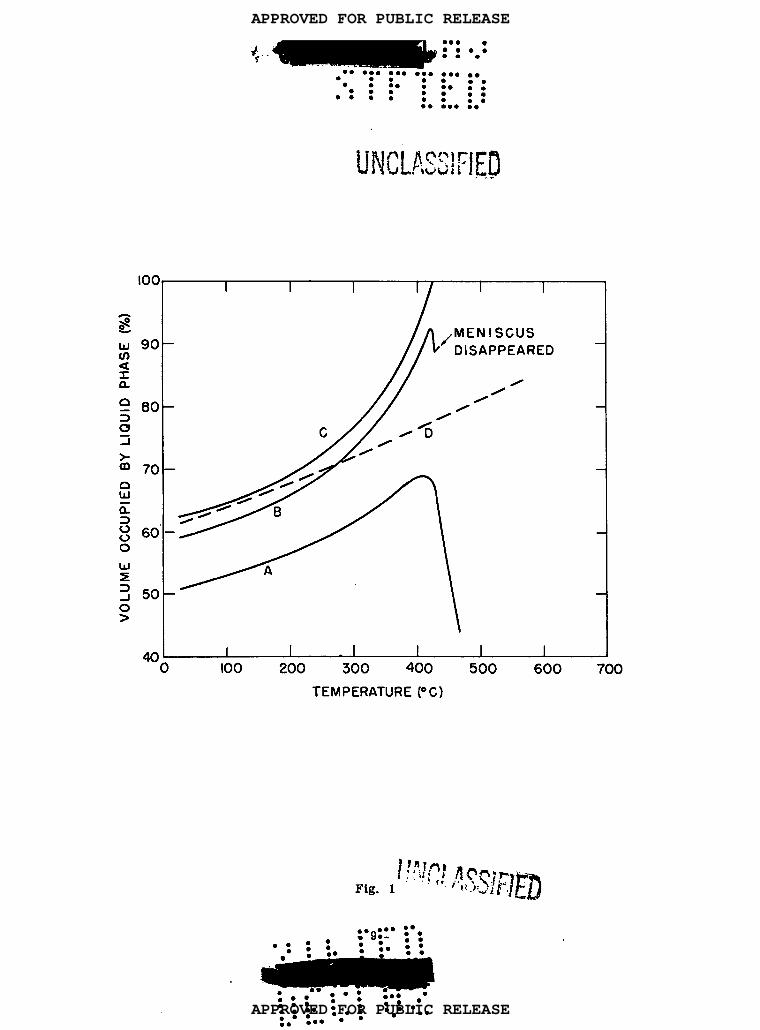
The manner in which the foregoing requirements have been incorporated in the design of
the LAPRE I will be understood from the schematic drawing in Fig. 3, and also from the
cutaway diagram in Fig. 4. The reactor vessel is made of 3-in. thick Type 347 stainless steel,
UNC\.ASSIFIE~::
iiii$ii.e*m:* ●:::● :.**● *m
●*.●*
APPROVED FOR PUBLIC RELEASE
APPROVED FOR PUBLIC RELEASE

● ☛ ● *9● ** ●=0 :● eae. .
8* ●✚✎✎✎✎✎✎✎● ● ☛
● O*.9* :● :0..
●
●°0:0:00.0
● *O●● 0
:● *
● ☛●
●
●☛✚● ☛
✚✚● ☛● 0● 9
r;L:,p? ,nnr”~~ rs..b~i “<‘.,”i.t.i l%,.,ji#’i”- -~1
since this material is corrosion resistant to the fuel solutlon at low tempera res. All
surfaces that come into contact with the hot solution are plated with a 0.005-in. layer of gold.
The interml diameter is about 15 in. and the section shown in Fig. 3 is approximately 8 ft
3 in. high.
The reactor proper consists of three volume regions, the design being such as to corn- “
pensate for the large increase in reactivity accompanying a decrease in temperature. The
bottom region, called the storage volume, contains a sleeve or “can” of boron carbide (en-
riched in boron-10) and a central boron rod which act as poisons, due to the large capture
cross section of boron for thermal neutrons. When the fuel solution cools, most of the
uranium is in the storage volume where the boron makes it definitely subcritical. The heat
exchanger, consisting of spirally coiled tubes of externally gold-clad stainless steel, through
which the cooling water flows, is part of the storage volume. At the bottom of the vessel
is an impeller which causes the fuel solution to circulate around the cooling coils (1, 000 gpm)
when the reactor is in operation. The sealed-rotor motor which drives the impeller floats
in fuel solution, but this region is kept cool by means of cooling coils and so does not require
gold plating.
The second region, above the heat exchanger, is the active core volume. When the
reactor is cold, it becomes critical when the fuel solution reaches the level shown, just below
the open top of the cone-shaped, platinum funnel. The volume of the storage region is 45.9
liters, whereas the cold critical volume is approximately 69 liters. Upon expansion at the
operating temperature, the fuel solution fills the active core region and makes it just critical.
The total volume of the fuel solution at 430°C is then 97.5 liters; it contains ‘7.7 kg of
urantum-235, of which 3.8 kg are tn the core region.
The location of the heat exchanger within the pressure vessel but external to the active
core has a number of advantages. In the first place, the circulation of the corrosive and
radioactive fuel solution through an external heat exchanger is avoided. At the same time,
the core volume can be kept small because the neutron poisons present in the cooling coils,
etc. , are not actually within the reactor core.
Above the core region is the vapor volume of 24.6 liters. The radlolytic gases and
water vapor collect in this volume, and it also holds the additional oxygen at 200 psi for
maintaining the chemical stability of the U(VI) -H3P04 system.
Between the vapor and core volumes is a heavy, gold-plated baffle of stainless steel
which serves a number of purposes. In the first place, it deflects and directs the flow of
the fuel solution that is being circulated by the action of the impeller. In addition, since it
is heavy, it absorbs a considerable amount of gamma radiation from the core, thus decr=sing
. . ● a* ●O
“iiddk!i.*8m0.0. .*-.. *9: ● ● ●*-.;.● *:...99
APPROVED FOR PUBLIC RELEASE
APPROVED FOR PUBLIC RELEASE

● ☛..’ m:*.
‘:’‘“iakm..● 99 ● ** ● ** ● ** ● *● O ● ● *
●: ● .: ●::. *:C :9,*9 :a
● . ● . ●
LEVEL
COLD CRITICALLEVEL
BORON CARBIDEllCAN1f ( POISON)_
lMPELLER _
0000
0
+
— CONTROL ROD-/-
Fig. 3
THIMBLES
_VAPOR VOLUME
_BAFFLE
—ACTIVE CORE
VOLUME
_CHIMNEY
_HEAT EXCHANGER
~TORAGE
VOLUME
I
APPROVED FOR PUBLIC RELEASE
APPROVED FOR PUBLIC RELEASE
. ....
.....
.
.
i. —t=- .—.. .. .
●
.
—..—~.%, _.—_- .–.-5. ..-.....- —
9“●.
1 ,STEAM OUTLET
I‘ LID
\ WATER
k
INLET
(?l.-
*
,VESSEL
/jk!&!!E
b.-.= .-. : !
.1 il. PPER PUMP- —-= -.-– –– “’!!OOLER. .. .. :.
Fig, 4
9
iikkkik.9 **..** .0.
. ● ●**.0 -:.:.● .: OO. O● m
APPROVED FOR PUBLIC RELEASE
APPROVED FOR PUBLIC RELEASE

● 0●
●9● *
●
●°:● *● *be
● *
the absorption by (and resultant
also serves as a poison for the
which the fuel solution can rise,
heating of) the top cover of the reactor vessel. The baffle
vapor volume and provides a narrow annular region wtthin
if necessary, without producing an appreciable change in
criticality due to a change tn volume of the reactor core.
Heat Exchamzer and Steam Svstem
The heat exchanger consists of 22 closely spaced spiral coil tubes of stainless steel
wtth 0.006 in. of gold cladding, The tubes are of 1/8 tn. i. d. and 3/16 in. o. d., the length
of each being 34 ft. The total heat-exchange area is 38.5 ft2. The coolant is water which
has been highly purified so that it contains less than 1 part per million of dissolved matter,
gaseous and solid. This water is pumped into the heat exchanger at the (supercritical) pres-
sure of 3, 900 psi. It will enter at 38°C (l OO°F) and the supercritical steam formed will
leave the heat exchanger at 427°C (800°F) and 3,600 psi. The advantage of operating under
these conditions is that the water is always present as a single phase. With steam of such
good quality, the efficiency of a thermal cycle should be high. However, since the LAPRE I
is largely experimental, the steam will be dumped and no attempt will be made to produce
electricity y.
Controls
The control system, to be used mainly in start-up and shut-down, consists of five10
vertical boron rods enriched in the neutron-absorbing isotope B . The rods move inside
heavy-walled, platinum clad stainless steel thimbles. Four of the rods, placed symmetrically
at the diameter of a 6-7/8 in. circle, reach only into the core region, but the fifth rod, in
the center of the vessel, extends to the bottom of the heat exchanger. The reactivity eff active-
ness (6k) of the off-center rods is estimated to be about 1.8 per cent, whereas that of the
central rod is 2.8 per cent.
The control rods are moved in their vertical thimbles by two-phase, two-pole induction
motors. The minimum withdrawal time of the central rod is about 2 min and that of the
smaller rods 1-1/2 min. The motor circuit is arranged so that rods can be withdrawn only
one at a time, and in a certain sequence, thus minimizing the danger of start-up with a
reactor period that is too short for safety.
The rods are attached to the withdrawing mechanism through d. c. lifting magnets. In
an emergent y shut-down (or scram) the magnets are de-energized, so that the rods will fall
freely into the reactor under the acceleration of gravity. It is estimated that about 0.3 sec is
required, after the appropriate signal is received by the safety circuits, for the rods to drop
two-thirds of the way. After a scram, the rod-withdrawing circuit will not function unless all
UNCLAs~~F~~●O
●
●
APPROVED FOR PUBLIC RELEASE
APPROVED FOR PUBLIC RELEASE
b. ● .* 8** .s768. . .8 ● .ee
● : ● .● e
co::● :.. : S*
: .
the rods are fully inserted, thus making it impossible to start up with a rod stuck part way
out.
Among the signals which will cause a scram are too short a period during start-up,
too high a neutron flux level, excessive temperature of the fuel solution, excessive pressure
in the reactor vessel, leak of radioactive material from reactor vessel or into cooling system,
failure of circulating or cooling-water pumps, and failure of power supply. In addition, there
is a manual switch on the control console which permits the operator to scram the reactor
at any time.
If the pressure in the reactor vessel should get too high, the solution can be emptied in
a few seconds through a rupture disc and a 5/8-in. id. pipe to a dump tank having a non-
critical geometry, i. e. , its long and thin cylindrical shape makes it impossible for the
solution to attain criticality. The rupture disc is set to release the solution when the pres-
sure in the vessel reaches 7, 500 psi.
Neutron level indicators, which are connected to the control system, are of the type
commonly used in reactors. At very low fluxes boron (BIO) counters are employed and
these are replaced by compensated boron ion-chambers in the period and power ranges.
Numerous thermocouples, for temperature measurement, and Baldwin cells, to indicate pres-
sures, are located at various points inside and outside the reactor vessel, and also in the
solution handling equipment.
Reflector and Shield
In the LAPRE I the reflector and part of the shield are the same, namely, the 3-in.
layer of steel of which the reactor vessel is made, surrounded by a 4-ft thickness of water.
Because of the latter, many of the neutrons leaving the core will be captured and those that
escape will be slowed down. However, the gamma radiation will not be greatly attenuated.
The shield proper is then made up of a 10-in. layer of lead followed by 5-1/2 ft of ordtnary
concrete. The nature of the shield will probably restrict operation of the reactor to about
2 Mw.
It may be mentioned, incidentally, that the heating due to the absorption of gamma rays
by the thick steel walls of the reactor vessel sets a limit on the power level, ,@ any event.
Calculations indicate that this heating produces thermal stresses comparable with the internal
pressure at an operating power of 2 Mw. It appears, therefore, that if power levels greater
than a few megawatts are required, internal cooling of the walls of the pressure vessel would
be necessary.
w.0 .:. .**:::. ..O . 8 ●**
● =● m ..* 9
APPROVED FOR PUBLIC RELEASE
APPROVED FOR PUBLIC RELEASE

Temperature Effects
The properties of the U03-H3P04 fuel solution are such that a negative temperature
coefficient of reactivity would be expected. However, because of the particular reactor
geometry, it is believed that the temperature coefficient iS Positive below 300°C, if the tem-
peratures are the same tn the storage and active core regions. The reason is that as the
temperature is increased, from low values, expansion of the liquid in the storage volume forces
additional uranium into the core region, thereby increasing its reactivity. This gain is par-
tially off set by the decrease in density of the solution. But at low and moderate temperatures,
the increase predominates, so that there is effectively a positive temperature coefficient of
reactivity. As the temperature increases, the positive coefficient becomes smaller, and at
about 300°C it is zero. At higher temperatures, which are of interest for operation of the
reactor, the effect of the density change is dominant and the reactivity temperature coefficient
is negative.
A positive temperature coefficient is hazardous, especially during start-up, because the
neutron flux (and power output) may rise too rapidly for safety. It appears that it can be
eliminated, however, by a start-up procedure which maintains the temperature in the storage
regton at least 60°C less than that in the core. At a given core temperature there will
then be less uranium in the core volume than would be the case if all the fuel solution, in
both core and storage volumes, were at the same temperature. When the core volume reaches
300°C, the temperature cliff erential need no longer be maintained.
At operating temperature, an increased power demand on the reactor is accompanied by
a drop in the temperature of the solution, since more heat is removed in the heat exchanger.
The solution contracts and the increase in density results in an increase of reactivity. The
fission rate in the reactor then builds up until the power demand is met and the temperature
returns to its initial value. At the same time the reactivity decreases to the point at which
the fission rate is constant and corresponds to the new power demand. Similarly, a decrease
in the demand will be rapidly followed by the appropriate automatic adjustment of the fission
rate at the lower level.
Another factor which contributes to the self-regulating property of the reactor arises
from the presence of the baffle between the reactor core and the vapor volume. If the
temperature of the core increases, some of the fuel solution will expand into the vapor region.
The neutrons from the solution above the baffle are then largely screened from those in the
reactor core, i. e., below the baffle. Thus, expansion due to an increase in temperature has
the effect of removing some of the fissionable material from the core and so decreasing its
reactivity. As a consequence e, the normal negative temperature coefficient, due to a decrease
I
I
I
APPROVED FOR PUBLIC RELEASE
APPROVED FOR PUBLIC RELEASE
● 99*-... .-● 0, ● -O 6 ● -* ● --● o**m*●
● 0 ●:0 :.. .:. :O. ..
● ● *
in density, is accentuated.
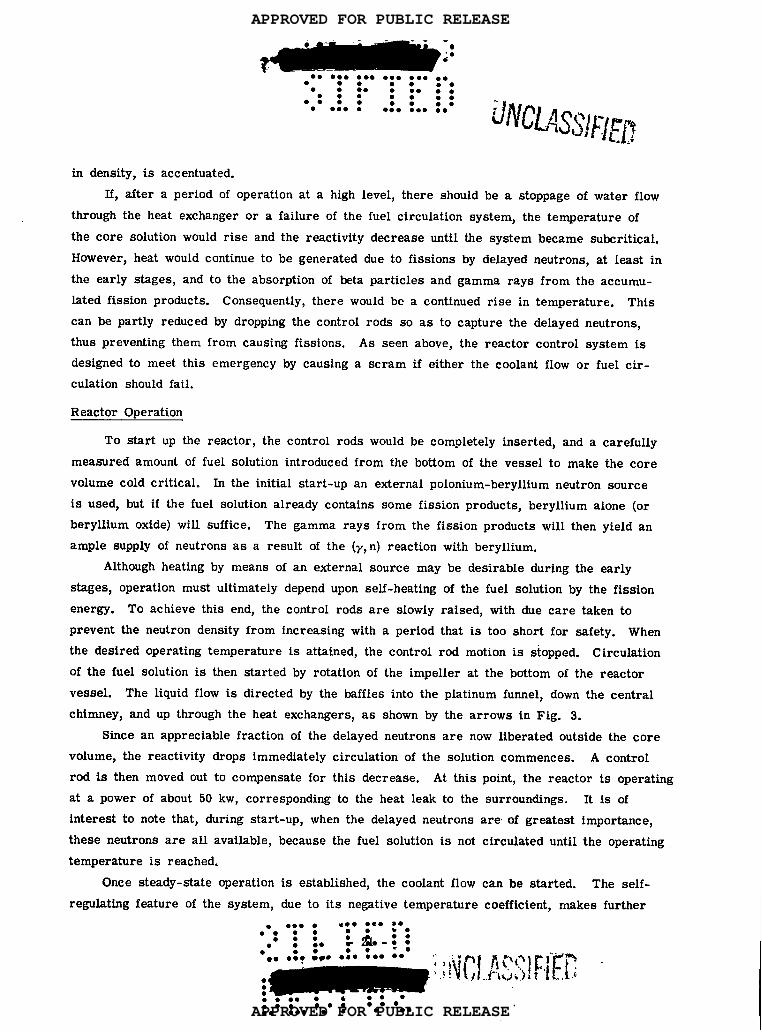
If, after a period of operation at a high level, there should be a stoppage of water flow
through the heat exchanger or a failure of the fuel circulation system, the temperature of
the core solution would rise and the reactivity decrease until the system became subcritical.
However, heat would continue to be generated due to fissions by delayed neutrons, at least in
the early stages, and to the absorption of beta particles and gamma rays from the accumu-
lated fission products. Consequently, there would be a continued rise in temperature. This
can be partly reduced by dropping the control rods so as to capture the delayed neutrons,
thus preventing them from causing fissions. As seen above, the reactor control system is
designed to meet this emergency by causing a scram if either the coolant flow or fuel cir-
culation should fail.
Reactor Operation
To start up the reactor, the control rods would be completely inserted, and a carefully
measured amount of fuel solution introduced from the bottom of the vessel to make the core
volume cold critical. In the initial start-up an external polonium-beryllium neutron source
is used, but if the fuel solution already contains some fission products, beryllium alone (or
beryllium oxide) will suffice. The gamma rays from the fission products will then yield an
ample supply of neutrons as a result of the (y, n) reaction with beryllium.
Although heating by means of an external source may be desirable during the early
stages, operation must ultimately depend upon self-heating of the fuel solution by the fission
energy. To achieve this end, the control rods are slowly raised, with due care taken to
prevent the neutron density from increasing with a period that is too short for safety. When
the desired operating temperature is attained, the control rod motion is stopped. Circulation
of the fuel solution is then started by rotation of the impeller at the bottom of the reactor
vessel. The liquid flow is directed by the baffles into the platinum funnel, down the central
chimney, and up through the heat exchangers, as shown by the arrows in Fig. 3.
Since an appreciable fraction of the delayed neutrons are now liberated outside the core
volume, the reactivity drops immediately circulation of the solution commences. A control
rod is then moved out to compensate for this decrease. At this point, the reactor is operating
at a power of about 50 kw, corresponding to the heat leak to the surroundings. It is of
interest to note that, during start-up, when the delayed neutrons are of greatest importance,
these neutrons are all available, because the fuel solution is not
temperature is reached.
Once steady-state operation is established, the coolant flow
regulating feature of the system, due to its negative temperature
circulated until the operating
can be started. The self-
coefficient, makes further
APPROVED FOR PUBLIC RELEASE
APPROVED FOR PUBLIC RELEASE

9 **9 ● *O. ..9 **9 ● ●°:
● ☛ 9** ● a* ● 00 ● .* ● e w● . ● 0..0: : .:00
adjustment of the
for fuel depletion
control rode unnecessary, except in so far as it is needed to compensate
(or burn-up) during operation~ The power is adjusted by varying the flow
of feed water through the heat exchanger. Only when it is required to shut the reactor down,
either deliberately or as the result of an emergency, are the control rods dropped. If the
reactor is not to be started up for some time, it would be advisable to empty the fuel solution
into a storage vessel with a noncritical geometry. Facilities for cooling the solution, to
remove the heat generated in fission product decay, are available.
Performance Studies
Since the LAPRE I is not intended to be a power reactor, but
ment to provide information that can be applied in the construction
rather a reactor experi-
of a power reactor, it
will be used for a variety of experiments and tests. Among these will be studies of (1) re-
actor response to changes in the power demand, i. e., the dynamic behavior of the system,
(2) heat transfer efficiency of the heat exchanger, (3) the quality and quantity of the steam
output, (4) changes in the solution and gas composition during extended power operation,
(5) changes in pressure with operating time, (6) the effect of solution temperature on reactor
performance, (7) stresses in the reactor vessel, (8) radiation lealmge through the shield and
build-up of radioactivity in the shield water, and (9) radioactivity of the steam. With the
information gained it is hoped to determine the limitations of the present design and the
modifications required to remove some of these limitations.
be obtained concerning the possibility of design changes that
improvements in operation of the reactor.
Further, some indication may
would lead to simplifications and
LAPRE II
The second Los Alamos Power Reactor Experiment, called LAPRE II, differs from
LAPRE I, described above, in two main respects, namely, in the nature of the fuel solution
and tn the method of circulating the high temperature solution through the heat exchanger.
The fuel solution for LAPRE II is to consist of 0.25 to 0.3 M U02 (93.5 per cent U235) in
17.5 M H3P04, and this has two advantages over that used in LAPRE I. First, the employ-
ment of the uranium in the U(IV) state results in improved catalysis of the hydrogen-oxygen
recombination reaction. The equilibrium pressure of the radiolytic gases is thus less than 20
psi at the operating temperature of 430°C. Second, at this temperature, the vapor pressure
of the solution is less than 800 psi, compared with over 3,500 psi for LAPRE I. Thus, in-
cluding an overpressure of 200 psi of hydrogen, the total pressure will probably be not more
than 1,000 psi. This means that a thimer reactor vessel can be used than for LAPRE I.
APPROVED FOR PUBLIC RELEASE
APPROVED FOR PUBLIC RELEASE

9* 9**●***99: ● 0●** ●● ream. s. . .
9* ● *9 9*O ● *9 ● 9O ● *@ ● **e
● *9* ● e ::● e :0. .● :
b ●:0 : 9*●:0 :** ● 0
uNc!.Ass/E;E
It will be recalled that in LAPRE I the fuel solution is circulated by means of an im-
peller driven by a sealed-rotor motor. In LAPRE II, however, circulation is by free (or
natural) convection. The hot solution in the core region rises and flows over the coils of the
heat exchanger, where it is cooled. The resulting increase in density then causes the solution
to flow down into the core where it is re-heated, and so on. This free convection coolingsystem is less efficient than one using forced flow, but it is obviously much simpler in oper-
ation, since no moving parts are involved. Where simplicity and reliability are important
considerations, as for operation in remote locations, the LAPR E II would appear to have a
significant advantage in this respect.
General Design
The reactor vessel of the LAPRE II is to be of 5/8-in. thick stainless steel (Type 316),
about 15 in. i. d., clad internally with a O.01-in. layer of gold. The vessel has three matn
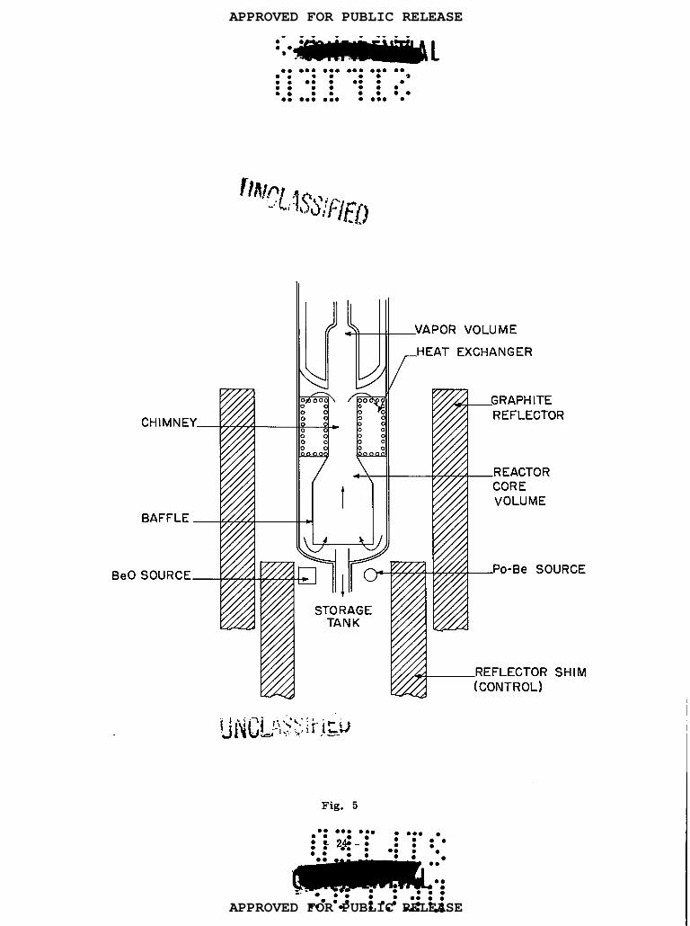
regions, shown in Fig. 5 and in the cutaway diagram in Fig. 6. The bottom region (about
66 liters) is the core volume; next is the heat-exchanger region (about 34 liters), and fimlly
the vapor region (about 7 liters). Approximately 88 liters of fuel solution expand to 100
liters at the operating temperature of 430°C. The critical mass of uranium-235 varies with
the conditions, e.g. , reflectok shim control and actual concentration of fuel solution, but it
will be of the order of 4 or 5 kg.
A central chimney and baffle of platinum will extend from the heat exchanger down into
the core region. It will be narrow at the top, widening out at the bottom, as seen in Fig. 5.
The purpose of the baffle is to direct the flow of the fuel solution by mtural convection, as
shown by the arrows. The solution heated by fissions in the core volume will rise up inside
the baffle. When it reaches the narrow (chimney) region, surrounded by the heat exchanger
coils, its velocity is increased. The solution then flows outward and downward, through the
heat exchanger, and re- enters the core volume by the annular space between the baffle and
the wall of the reactor vessel. The velocity of circulation of the fuel solution by free con-
vection is estimated to be about 1.5 ft/sec through the chimney.
The heat exchanger will consist of 44 stainless steel (gold clad) coils, each being 21 ft
in length, 3/16 in. o. d., and 1/8 in. i. d. The total area, for a power output approaching
1 Mw, will be about 31 ft2. In the experimental system, the highly purified water will enter
the heat exchanger at 55°C (150°F) and 800 psi, and leave at 315°C (600°F) and 600 psi pres-
sure. The coolant flow rate will be roughly 4-1/2 gpm and the over-all heat transfer co-
efficient will be about 310 Btu/(hr) (ft2) (°F).
In the LAPRE II, at least in the early stages, no use will be made of the steam, but tf
it were to be utilized for power production, the steam would go to a secondary (external) heat
APPROVED FOR PUBLIC RELEASE
APPROVED FOR PUBLIC RELEASE
9* * ● **● 9*9 0 .** ● ●°:
● 9*89 ● .**●
✚☛☛
● ☛ ●9: ●:0 ● ** ●:0 ● 9s. *● emm* ●:.9● 00: ●be : :*
● * ●0: ● oe ● ●:* ●
CHIMN
BAFFL
SOURC
\
o000
.
I
Fig. 5
_VAPOR VOLUME
f
HEAT EXCHANGER
E
M
● e ● O9 ● O. ● ● e* .
:: 4.::::.:: .:.: _
‘-;●:: ● 0**● 0:
● b.ae ● **● 00 .*
APPROVED FOR PUBLIC RELEASE
APPROVED FOR PUBLIC RELEASE

● 9 ● 00 9*● *em”*: ●°9 ●
~“J” .$%7 ,- ~’....
e i-,..$ 43\ .-, -j
-,0.....”.. ,., t
. .
,.. . . ... Cu~-..a; .: .== -,<.
.—. . . .
. . . . . .
.-..d’. -a~_,.— ., ____ .. ..._ .
9* ● ** ● 80 99* 9*9 ● *● .**9
● cob ● ●0::● em *m*● :00 ● *<*** ●:0 :00 ● 0
LINER
\!— ---. ...,a:‘d-~ _:FEED ~ATERUANIFOLD
~~=i:’: ,STEAUMANIFOLD-. ..—.L=-—..-.ViT.-m:.-n:.n:.-? \..— . . .——.,,
u,.--:- l.. .%@?. -.—--’ : A —i.!.-= :-.~..-,, .-. -.— —-_.-.,-. .G. G .——. —
~my—-”--- ‘-””
EXCHANGER—. \——— .———.=,
,,,,.!
,,
,,
‘-1
L@jr
I
a!!!!!d—?———JI—-. _. . J L—- . . . .
EARTH
-.
48”
1.,, .,, ..’ -
------ . . . ,-.
F~& ALNVK)SPOWER REAc~o;-—:%..-:.-._....._.m-.~XPERl.MENT NUMBER 2.A#r-vfl- c -&!G-a-. .-==,-.._.-... .. —.;.=,=.—_. .. ... _. .. LAPRE-11,“—--.9,.f--SE*?.--—.—... OCTOBER3, 1955
Fig. 6
9* :*
:!*● **O* 99*C3** 9*: ● 6*,. B* O*** **
?
APPROVED FOR PUBLIC RELEASE
APPROVED FOR PUBLIC RELEASE

● ☛ ● ● 9*9 ●’* ● .O. ● ●°:. ● 9..** . .
9- i●~1 .
exchanger. Here fresh steam would be generated in another circuit for driving the turbo-
generator. The secondary system is introduced to avoid the possibility of contamination of
the turbine by fuel solution coming directly from the reactor due to a leak in the cooling coils.
No radiation shielding will then be required beyond the secondary heat exchanger. If the
possibility of leakage into the steam system could be obviated, e. g., by high steam pressures,
then the secondary heat exchanger could be eliminated.
The reflector (see Fig. 5) consists of two concentric sleeves of graphite, 6-in. thick,
one ftxed and one movable. The latter also acts as a manually operated shim control. When
it is lowered, as in the figure, neutrons can escape from the core, thus decreasing its reac-
tivity. On the other hand, if the reflector shim is raised, more neutrons return to the core,
LIl~ blllrn CUIILIWL 1S ~X-
adjust the operating tem-
so that the reactivity increases. The reactivity equivalent (6k) of ‘L- -L:—. -_ -A-- , ,- ---
petted to be about 10 per cent.
Controls
Apart from the reflector shim control, which will be used to
perature, no other controls are contemplated for the LAPRE II. Reliance for operating
control wtll be placed completely in the self-regulating properties of a reactor using a
uranium-phosphoric acid fuel solution. An increase in power demand will be accompanied by
a decrease in reactor fuel temperature and a consequent increase in reactivity to satisfy
that demand, as described in connection with the LAPRE I.
The only control adjustment that may be necessary during an extended period of reactor
operation is to compensate for the fuel consumption (or burn-up). This adjustment can be
reduced to a minimum by including a “burnable” poison, e.g. , boron or lithium in the fuel
solution. The initial concentration of the poison, e.g. , 0.005 M boron-10, is such that it is
consumed by neutron capture, at about the same rate as the fissionable material. Sufficient
uranium-23 5, in excess of the critical mass, is included in the fuel solution to allow for
burn-up durtng the operating period of 2 or 3 years, i. e., about 1 kg for 1 Mw power. The
accompanying excess reactivity is then removed by the boron poison. As the reactor oper-
ates, the uranium-235 is burnt up and the excess becomes less and less. At the same time,
the boron is consumed, so that its poisoning effect decreases correspondingly. The actual
reactivity of the system, at a given temperature, thus remains essentially constant over a
period of operation.
Since it is almost a practical impossibility to achieve exact reactivity compensation,
especially since fission product poisons are formed during operation, there will be a tendency
for the temperature of the core solution to change somewhat during the course of time. This
will, in turn, affect the steam temperature and pressure. The variations will probably be
APPROVED FOR PUBLIC RELEASE
APPROVED FOR PUBLIC RELEASE

● ☛ ● *m ● ** .** .** ● *● ● ● *
● : ● 0 ● 9 ::● 9 :e● :0 ● *
● *● : 9:C :00 ● O
small and tolerable, but they can be reduced by manual adjustment of the reflector shim con-
trol once or twice a year.
It would not be a difficult matter to design a servosystem that would automatically and
continuously adjust the shim control. But one of the basic purposes of the LAPRE II design
is to provide a power reactor of the greatest possible simplicity, requiring the absolute
minimum of maintenance. The instrumentation, mechanism, motors, etc. , required for auto-
matic servo-control are thus considered to be undesirable.
Start-up and Operation
In starting up, the reactor vessel is first evacuated and then hydrogen is admitted at
about 1 atm pressure. This gas will subsequently be compressed by the fuel solution to give
the required hydrogen overpressure (about 200 psi). The reflector shim is raised so that
about two-thirds of the core region is covered. Cold fuel solution, of the appropriate con-
centration, contained in the noncritical reservoir tank, is then forced by hydrogen pressure
into the bottom of the reactor vessel. As stated above, the flow rate is limited to prevent
a too rapid tncrease in reactivity and the attainment of a very short reactor period.
When sufficient solution has entered the reactor to reach the cold critical volume (about
25 per cent filltng), the solution begins to heat up at such a rate that its negative temperature-4
coefficient (-5.7 x 10 per ‘C) compensates for the excess reactivity due to further addition
of fuel. Neutrons for initial start-up are supplied by a polonium-beryllium source, just below
the reactor vessel. Subsequently, when gamma-ray emitters are present, a block of beryllium
oxide serves as a neutron source. During initial start-up, neutron multiplication will be
observed by means of one or more neutron chambers placed outside the enclosure tank. In
addition, temperatures till be measured by means of a thermocouple at the bottom of the
reactor vessel.
As the core volume fills with fuel solution, the temperature rises and convection circu-
lation begins when the level of the liquid reaches the heat exchanger. When the solution just
covers the top of the heat exchanger coils, and the reactor is about 95 per cent full of solution,
the operating temperature (43 O°C ) should be obtained. If the actual temperature cliffers only
slightly from that desired, the necessary adjustment can be made by moving the shim cent rol –
up, to increase the reactivity, if the temperature is too low or down if it is too high. If
there is a substantial difference between actual and design temperatures, the uranium concen-
tration of the solution can be changed. Once the proper conditions have been established
during start-up, subsequent operation is controlled entirely by the power demand, except for
occasional adjustment of the reflector shim control.
● ● ☛☛ ● 9
● 000 ●
● O* :0● 0:00: ● -$~- UNCUNWIED
● ●
●*●:0 ● 00 ● *O ● *8 ● O
●● 9*● 00 ● ● ** ●
:::0 : ●
● 0: ::0● .* Om O** ● *
APPROVED FOR PUBLIC RELEASE
APPROVED FOR PUBLIC RELEASE

● m ● ● *O● ●°0 ● 9*9 ● ●o:
● ● 900099 ●●
#UMMWl#l● ✎ .08 .OO ,08 ..O .0
● 9 ● ● 9● 00:0 .:00● *** ●● e : :00
● 0 ●0:●:0
(JN,A] ‘nol” “bb hub)] FIED
To shut the reactor down completely, e. g., for replacing the fuel solution every 2 or 3
years or in the event of a leak in the reactor or heat exchanger, the solution would be drained
into the fuel reservoir tank. This reservoir, with a capacity of 110 liters, has a noncritical
geometry. By means of an independent cooling loop and radiator system, the discharged fuel
solution can be kept below 100°C (212°F).
Because of the simplicity in design, instrumentation of the reactor system, except prob-
ably during start-up, will be minimal. Essentially all that will be necessary is to observe
the temperature of the fuel solution, and the inlet and outlet temperatures and flow rate in
the secondary steam system. From the latter, the power output of the reactor can be deter-
mined and controlled.
Safety
Although the LAPRE II has no conventional, emergency (scram) shut-down, there are
sufficient safety features to deal wtth all foreseeable hazardous situations.
One danger appears to be the possibility of excessive temperatures (and pressures) in
the reactor vessel. In this event, the fuel reservoir vent valve,
would open and the excess pressure in the reactor vessel would
the noncritical reservoir, described above.
The reactor vessel itself is enclosed in a cylindrical tank,
This tank has duplicate relief valves set to blow off at 250 psi.
set to operate at 1,300 psi,
force the fuel solution into
made of copper-lined steel.
If the reactor vessel should
burst or there should be accidental flooding of the enclosure tank due to a ruptured feedwater
line, the excess pressure would be vented into the waste-disposal system.
If any other type of failure should occur, e.g. > rupture of a heat-exchanger tube within
the reactor, which did not produce an immediately hazardous situation, the fuel solution can
be rapidly transferred to the reservoir by manually opening a dump valve. This can be used
to shut down the reactor at any time it may be desirable or necessary.
There are two additional features which are designed to make impossible a dangerously
short reactor period during start-up. In the first place, the rate at which the fuel solution
can enter the reactor is controlled by a flow-limiting orifice on the pressurizing gas line of
the fuel reservoir and by a preset pressure on the injection line. The maximum rate of fuel
solution input is about 1.2 liters,’min, corresponding to an increase in reactivity at the rate
of 10j!/see, i.e., 0.00075 per sec. In addition, the rate at which the reflector shim control
can be raised, by a hand-operated crank, is limited to give the same maximum rate of reac-
tivity increase.
● e ● ** ●● e ●
:● ● O
-:28 -.. : .: : ●e● . . .
● * ● ** 9** ●.: ●:. ● *●
●
● 0.. ● O*●
9*.●● ::..: ● ***
● ***. ● om● m. . .
APPROVED FOR PUBLIC RELEASE
APPROVED FOR PUBLIC RELEASE

● ☛ ● 00 ● 9● *9 9*O: ●°0 ●● 9bma*m ● -
● 0 9*O ● 9* ●:. ● O* ● *9*. ●
● e**** ● ::● **9 ● *● :e ● * ● m● : ● * ● *a ● * UNC”LAW’IED
Push-Pull Circulation
The purpose of the Push Pull Critical Experiment (or PPCX) is to test an idea for the
forced circulation of a hot reactor fuel solution through a heat exchanger without the use of
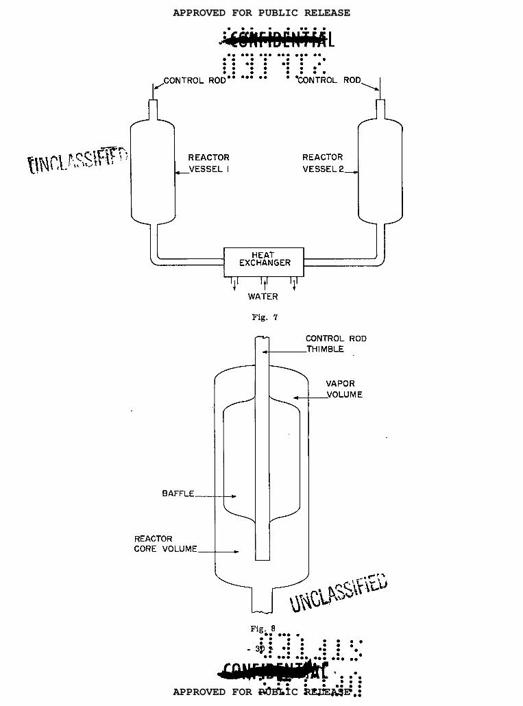
a device having moving parts. The basic principle of the PPCX may be explained with the
aid of Fig. 7. The proposed arrangement consists of two similar reactor vessels connected
together at their bottom ends through a heat exchanger. The system is filled with enough
fuel solution to allow one reactor vessel to become critical when the other is essentially
empty.
Suppose vessel 1 is filled with solution to the critical height and the control rod is
withdrawn, so that there is sudden increa~e (or burst) in power. The temperature of the
solution increases and so also does the pressure in the vapor volume above the solution.
pressure in vessel 1 is now greater than that in vessel 2, so that the heated solution is
fuel
The
forced through the heat exchanger into vessel 2. The partially cooled solution enters vessel
2 and when the critical height is exceeded, a power burst occurs in this vessel. As a result,
the solution is returned, through the heat exchanger, to vessel 1. The to-and-fro movement
of fuel solution from one vessel to the other has been called “push-pull”. Once the process
has been started, it will be repeated continuously with a power burst occurring alternately
in each vessel, the heat being removed from the solution during the time between the bursts.
The general design of the reactor vessels is indicated in Fig. 8. The core volume, at
the bottom, is separated from the vapor volume, at the top, by means of a baffle. If, during
a power burst, the fuel solution expands above the bottom of the baffle, the excess solution
will occupy the annular space between the baffle and the wall of the reactor vessel. Because
of the geometry and the poisoning effect of the baffle, this solution makes no appreciable
contribution to the core reactivity, thereby introducing an element of safety into the system.
Analysis of Push-Pull System
The operation of the push-pull system depends on the ability of the excess vapor pres-
sure plus the overpressure of noncondensable gas in vessel 1 over that in vessel 2, for
example, to support the hydrostatic pressure of the solution in vessel 2. The vapor pressures
depend on the temperatures in the two vessels and, in addition, the overpressure will be
determined by the respective vapor volumes. The overpressure may be due to radiolytic gas
plus excess hydrogen or oxygen included to maintain stability of the desired oxidation state
of the uranium in the fuel solution. It will be apparent, in a general way, that there would
be more or less precise conditions under which the push-pull behavior can occur.
● ● ☛☛ be
● 00::: ::● a● O:*:
●:“ -:% -
● Q ●:e. ● * ● ** ● *. ● *
.** ●-1
●**:: .0 b
● O** .*9
.** ● *9 ● -.
.. *ma*** ● 9
APPROVED FOR PUBLIC RELEASE
APPROVED FOR PUBLIC RELEASE
● O ● ● om● ●’* ● ●9* ● ●o:
● ● *9* ● e.w●
AHHBUU#l● ✎ ● 9* ● ** ● 0-
● * ●● 00:0 ●:::0
: :
~CONTROL ROD”” ““: ““ ●
/“-REACTOR
_VESSEL I
●:0 ● O●
9:● :0
“CONTROL ‘OD=A
BAFFLE_
REACTORCORE VOLUME_
REACTOR
VESSEL 2_
I I
‘J’ ‘t’ ‘1’WATER
Fig. 7
-9
CONTROLTHIMBLE
-i-
ROD
VAPOR
_VOLUME
Fig. 8● 9 ● 9* .
:: ●
.3$: .; : .;● * ● . . .: . . . . .
●
● ✚✚● me.*
● ● ✠9*
●:0● ** ,.
~● ●**● 9*
● 000● m.
● ** . .
APPROVED FOR PUBLIC RELEASE
APPROVED FOR PUBLIC RELEASE

A theoretical analysis of these conditions is difficult because of various complicating
factors. A study of the neutronic aspects is feasible using standard methods, so that the
rate of power increase can be calculated. But, in estimating the corresponding temperatures
and vapor pressures, difficulties arise. When the fission-heated fuel solution leaves a given
reactor vessel, the volume vacated by the solution must be filled with vapor by evaporation
of the remaining solution. As a result, the temperature of the solution falls while it is
emptying. The reverse is true in the other vessel into which the solution is flowing. The
vapor is condensed by compression and the temperature of the fuel solution rises. Although
it is assumed, for purposes of calculation, that the solution and vapor are always in equilib-
rium, it is doubtful whether this is the case.
The treatment of the heat removed in the heat exchanger is by no means straightforward.
This is because the direction of flow of fuel solution is reversed before it has passed com-
pletely through the exchanger. Suppose that when the solution begins to move out of vessel 1,
an equal volume of solution is contained in the heat exchanger. Then, the first volume ele-
ment of solution leaving vessel 1 will traverse the entire length of the heat exchanger, and
so will be cooled to the maximum extent. The last volume element, however, will return to
vessel 1 wtth no change of temperature, because at this time there is sufficient fuel solution
in vessel 2 for the direction of flow to be reversed. Incidentally, the heat exchanger will
have to be of special design, in any case, to allow for the fact that heated solution flows
alternately in opposite directions. In a conventional heat exchanger, the flow is, of course,
always in the same direction.
The power output of the push-pull system will be determined by the duration and shape
of tie power burst, the peak power, and the time between bursts. Design changes will make
possible variations tn these parameters, so that the power output can be varied accordingly.
Preliminary calculations indicate that average powers of the order of several megawatts should
be attained without difficulty.
Control
Provtded the calculations relating to the concentration of the fuel solution are reasonably
good, the operating temperature will probably be most easily adjusted by means of a reflector
shim control, as described for the LAPRE IL In addition, however, it may be desirable to
have a central control rod of a neutron absorber, such as boron, enriched in B . The10
control rod in each vessel would be able to operate quite independently of the other.
The control rtids could be used, if desired, to force the push-pull oscillations to occur
at a frequency slower than the natural frequency by altermtely inserting and withdrawing the
rods. By varying the cycle times in this manner, the power output of the system could be
changed. ● 8*8 ● *● * ● G
● :0 :0 -; 3i -● 0:0:: ● oe-e-,
● *● * ● O* ● ** ● ** ● *m ● * ,.~:;j ;:~’~:; i.!L:*Q“!.i
●● e*● *O:::0 ● be
● 09 ●e* ●
● m .bm 9 ● ● 9
APPROVED FOR PUBLIC RELEASE
APPROVED FOR PUBLIC RELEASE
● 0 ● 88 ● 90 ● =* 99* ● m● O ● 0● **: : ●: ●● om :*● 9 : :*OO
● m ●0: ● 0 ●
!l’Kv’&wm. ..-___Safety
One of the hazards of the PPCX lies in the fact that sustained operation appears to be
possible, according to calculations, only when the neutron density is increasing with a very
short period, so that the prompt critical condition is exceeded, i. e., the effective multipli-
cation (or reproduction) factor is greater than 1.0075. In these circumstances there is
always the possibility of an accident. Suppose, for example, that the experiment were quiescent
for some time, so that the fuel solution in the heat exchanger became cooled to the inlet
water temperature. Upon re-starting the operation, a power burst would force the abnormally
cold solution from the heat exchanger into the empty reactor vessel. The power burst due
to the excessively large reactivity might be such as to cause serious damage.
Since the conditions just described would apply only when the operation is stgrted (or
re-started), they might be avoided by keeping the heat exchanger at an elevated temperature
during start-up. Another possibility is to have a valve between the two reactor vessels which
would permit the heat exchanger to be partially by-passed during the first few starting pulses.
The danger due to excess pressure in the reactor vessels could be minimized by con-
necting them through rupture discs to a noncritical dump tank. The discs would be designed
to break at about 25 per cent above the normal operating pressure. Some cooling of the tank
would be necessary as with other reactor systems.
Status of PPCX Project
Calculations based on a fuel solution of the type used in the LAPRE I have revealed no
fundamental fault in the push-pull concept. A combination of theoretical studies with experi-
mental work would undoubtedly indicate the optimum operating conditions. However, it now
appears that a U(IV) solution in concentrated phosphoric acid, such as is planned for the
LAPRE II, offers greater prospects for success tn a push-pull system than does the LAPRE I
fuel solution. As seen above, the former has a lower vapor pressure, at a given temperature,
and the recombination rat e of hydrogen and oxygen produced by radiolysis is greater. This
means a smaller total overpressure of noncondensable gases, which appears to be advanta-
geous.
The uncertainties in the operation of a push-pull system for circulating a U(IV)-H3P04
fuel solution are chiefly stability of operation and corrosion by the flowing solution. Since a
complete investigation of these matters will require expensive construction, it has been decided
that the PPCX shall remain in abeyance until further knowledge has been gained of the be-
havtor of uranium-phosphoric acid solutions in the operation of the LAPRE I and LAPRE II.
!Y’*!CUNIFIW.~..0
+2;-.::.:;
*;● *. ● 0:
●**. m ●0:
● O●
●●
● *
● :
::● O
● *
APPROVED FOR PUBLIC RELEASE
APPROVED FOR PUBLIC RELEASE

● 9 ● ** ●
●
9* ● 00 ● 00 9*9 ● 00 ● *● 9**
● :** *.* ::● *e** ●● :.** 9*
● e :** 9* i/ivclAyJf”//●
Treatment of Spent Fuel Solutions
From the over-all economic standpoint, the recovery of unused fissionable material from
spent reactor fuel (or fuel solutions) is a basic aspect of the reactor system, Because of the
accumulation of fission product poisons which capture neutrons and the possibility of the
formation of precipitates, as the result of continued reactor operation, the fuel solution must
be purified, either (more or less) continuously or after a considerable burn-up has been
achieved. In the LAPRE I, a quantity of partially spent fuel solution can be drawn off from
time to time. The fission products are then removed, as will be described below, and the
remaining solution, after adjustment of the uranium-235 concentration if necessary, can be
returned to the reactor. This may be regarded as essentially continuous processing.
The LAPRE II, on the other hand, is designed so that it will operate for a long period
without attention. In this case, there may be a burn-up of something like 20 per cent of the
fuel before poisoning, etc., becomes so serious that the solution has to be replaced. The
spent fuel solution, however, still contains 80 per cent or so of the original fissionable mate-
rial which must be recovered.
As indicated at the outset, homogeneous reactors using aqueous fuel solutions, such as
the LAPRE I and II, have a basic advantage as far as spent fuel treatment is concerned,
sine e the dissolution and refabrication of solid fuel elements is obviated. There is a further
benefit which should be mentioned. When fuel elements must be fabricated, a high degree of
decontamination of” the recovered fissiomble material from radioactive impurities is necessary
in order to decrease the hazard involved in handling the material. But when the fuel is used
in solution, such extensive decontamination is not necessary. The essential requirement is
only that a large proportion of the fission products which are strong neutron poisons be
removed from the solution. Not only is the processing of the spent fuel solution much simpler
and cheaper but, in addition, the inevitable loss of fissionable material is reduced.
As a result of work done by various AEC contractors during recent years, it has been
found that solvent extraction is a very convenient method for removing fission products from
uranium (or plutonium). The procedure is dependent upon the fact that uranyl nitrate, i.e. ,
U02(N03)2, in which the uranium is in the U(VI) state, is readily soluble in a number of
organic liquids, whereas the fission product nitrates are essentially insoluble. To a solution
containing U(VI), preferably as nitrate, is added a so-called “salting agent”, usually a neutral
nitrate insoluble in the organic liquid. The solution is then brought into intimate contact with
the organic
the organic
impurities.
solvent which is insoluble in water. As a result, two liquid layers are formed,
layer containing the U(VI), whereas the aqueous layer contains the fission product
The uranium can be re-extracted from the organic medium by means of water
. . . . ● 9
APPROVED FOR PUBLIC RELEASE
APPROVED FOR PUBLIC RELEASE
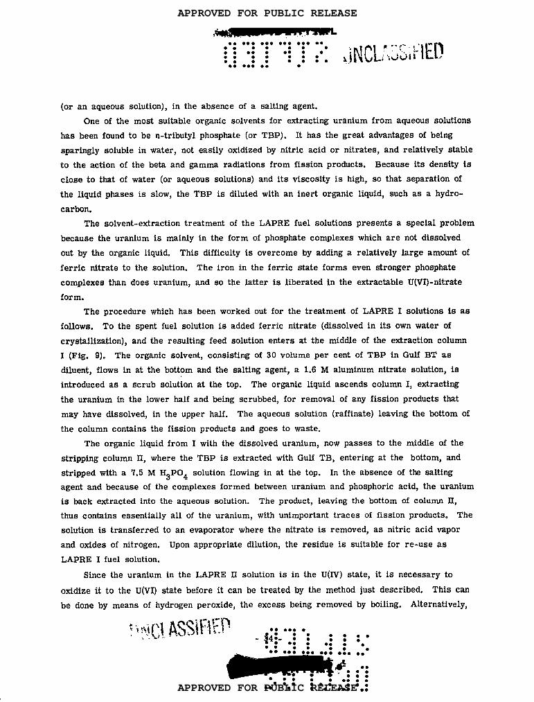
● 0 ● ● a*● ●°:. 9** ● ●**
● ● *9●●
● 0 ●0: ●:0 ● 00 ●:0 ● *● O ●
● eeee ●: ●● *** :0● a :000
● 0 ●0: ●: ●
(or an aqueous solution), in the absence of a salting agent,
One of the most suitable organic solvents for extracting uranium from aqueous solutions
has been found to be n-tributyl phosphate (or TBP). It has the great advantages of being
sparingly soluble in water, not easily oxidized by nitric acid or nitrates, and relatively stable
to the action of the beta and gamma radiations from fission products. Because its density is
close to that of water (or aqueous solutions) and its viscosity is high, so that separation of
the liquid phases is slow, the TBP is diluted with an inert organic liquid, such as a hydro-
carbon.
The solvent-extraction treatment of the LAPRE fuel solutions presents a special problem
because the uranium is mainly in the form of phosphate complexes which are not dissolved
out by the organic liquid. This difficulty is overcome by adding a relatively large amount of
ferric titrate to the solution. The iron in the ferric state forms even stronger phosphate
complexes than does uranium, and so the latter is liberated in the extractable U(VI) -nitrate
form.
The procedure which has been worked out for the treatment of LAPRE I solutions is as
follows. To the spent fuel solution is added ferric nitrate (dissolved in its own water of
crystallization), and the resulting feed solution enters at the middle of the extraction column
I (Fig. 9). The organic solvent, consisting of 30 volume per cent of TBP in Gulf BT as
diluent, flows in at the bottom and the salting agent, a 1.6 M aluminum nitrate solution, is
introduced as a scrub solution at the top. The organic liquid ascends column I, extracting
the uranium in the lower half and being scrubbed, for removal of any fission products that
may have dissolved, in the upper half. The aqueous solution (raffinate) leaving the bottom of
the column contains the fission products and goes to waste.
The organic liquid from I with the dissolved uranium, now passes to the middle of the
stripping column II, where the TBP is extracted with Gulf TB, entering at the bottom, and
stripped with a 7.5 M H3P04 solution flowing in at the top. In the absence of the salting
agent and because of the complexes formed between uranium and phosphoric acid, the uranium
is back extracted into the aqueous solution. The product, leaving the bottom of column II,
thus contains essentially all of the uranium, with unimportant traces of fission products. The
solution is transferred to an evaporator where the nitrate is removed, as nitric acid vapor
and oxides of nitrogen. Upon appropriate dilution, the residue is suitable for re-use as
LAPRE I fuel solution.
Stnce the uranium in the LAPRE II solution is in the U(IV) state, it is necessary to
oxtdize it to the U(VI) state before it can be treated by the method just described. This can
be done by means of hydrogen peroxide, the excess being removed by boiling. Alternatively,
●●
✚● *9
● O
●e:
9*●
●●
● *
APPROVED FOR PUBLIC RELEASE
APPROVED FOR PUBLIC RELEASE

●**9
**.*●
.
In
b“
L
..
...
9a
------—
●e
•o:;~.
●:90
●e:a::
●::
m5’
-----
U4@
miU
r...
**9●
**
APPROVED FOR PUBLIC RELEASE
APPROVED FOR PUBLIC RELEASE

● ✎ ● ☛☛ ● *O 9** ,00 ● m● * ● m● 00: : ●:00
● . ●9* :* : :00
● m ● m. .
ihlLL‘1 lJpr\reP+”Tji”dj~’-the ferric nitrate, added for the purpose of forming complexes with the phosphoric acid, can
serve to oxtdize the U(IV) to U(VI). The solution is then diluted, so as to make the phos-
phoric acid concentration about the same as for the LAPRE I solution. For the stripping in
column II, a 15 M H3P04 solution is used to give required final concentration of this acid
after the evaporation stage for removal of nitrate. The U(VI) in the solution is finally re-
duced to the required U(IV) state, e. g., by means of phosphorous or hypophosphorous acid.
In the compact solvent extraction system for treatment of the LAPRE solutions built at
Los Alamos, the flow rate of spent fuel solution is about 2/3 liter/hr. Consequently, roughly
5 1/2 days would be required for processing all of the fuel solution of the LAPRE II, for
example. Since this reactor is designed for long periods of operation, a processing time of
this duration is not significant.
The solvent extraction procedure is simple and effective, and lends itself very well to
the remote operation necessitated by the intense radioactivity of the solution. Nevertheless,
it is felt that an even simpler method of treating the spent fuel solution may be possible, and
work is proceeding with the object of developing such a process. As already mentioned, the
main requirement is the removal of most of the neutron absorbing impurities, and it con-
ceivable that this may be achieved even more easily than by solvent extraction.
Fast Reactor Systems
Breeding of Fissionable Material
It was stated earlier that, in addition to aqueous homogeneous reactors, the laboratory
is tnterested in the design of a fast power reactor using plutonium-239 as the fuel. For
reasons to be explained shortly, such a reactor should preferably be designed as a breeder.
Before discussing the details of the proposed reactor, a general outline will be given of the
basic principles which have to be taken into consideration in the design of a fast power
breeder reactor.
Although only one fissionable nuclide exists in nature, mmely, uranium-235, there are
two fertile materials, uranium-238 and thorium-232, which can be converted into the fissionable
species, plutonium-23 9 and uranium-233, respectively. The conversion, in each case, is the
result of two stages of beta decay followtng the capture of a neutron, the neutron being
produced by fission. If there is to be a real future for nuclear power based on fission, with
essentially complete utilization of the fertile materials, then the process known as “breeding”
must be a practical possibility.
Consider, for example, the system in which uranium-238 is the fertile material and
plutonium-239 is the corresponding fissiomble product. Suppose the plutonium is the fuel in
a reactor in which it undergoes fission. Of the fission neutrons produced, one is required
APPROVED FOR PUBLIC RELEASE
APPROVED FOR PUBLIC RELEASE

● **9**** ● .
● mmmam
● e ● *. ● 9* ● 00 ● O9 .● *mm*
● ***.. ● ::● O.*. ●● :e **m .0
to matntatn the fission
matnder of the fission
● ✎ 9,* *9
chain. Apart from loss by escape, it may be supposed that the re-
neutrons are captured either by uranium-238, with the ultimate forma-
tion of plutonium-239, or by the plutonium-239 fuel to form plutonium-240. If the number of
plutonium-239 nuclei formed exceeds the number destroyed, either by fission or by nonfission
capture of neutrons, then breeding has occurred. In general, the breeding ratio is defined by
Breeding ratio =No. of fissionable nuclei producedTotal no. of same nuclei destroyed ‘
and breeding has been achieved if this ratio is greater than unity.
In a thermal reactor, such a large proportion of the neutrons are captured by plutonium-
239 in the nonfission process, forming plutonium-240, that breeding is impossible. But with
increasing neutron energy, the parasitic capture of neutrons becomes relatively less impor-
tant, so that for sufficiently fast neutrons breeding can occur. The breeding ratio increases,
toward a limiting theoretical value of about 2, with increasing neutron energy, and an ideal
plutonium-239 breeder would be a fast neutron reactor, in which the great majority of the
fissions were produced by neutrons in the energy range above about 0.5 Mev. It may be
noted, in passing, that breeding of uranium-233 from thorium-232 is possible in a thermal
neutron reactor. However, because the sources of uranium-238 are considerably more abun-
dant than thos of thorium, the breeding of plutonium-239, in a fast reactor, is of greater
ultimate significance.
Fast Reactor Principles
Materials
If a reactor is to operate mainly on fissions caused by fast neutrons, it is essential
that neither core nor reflector shall contain materials capable of slowing down the neutrons
as a result of either elastic or inelastic collisions. Slowing down due to elastic scattering
is important for elements of low mass number, e.g. , below about 20, and the use of such
elements must be avoided. On the other hand, inelastic scattering, which is specific in
nature, varying from one element to the next, is generally more effective in collisions of
neutrons with nuclei of high mass number. Exceptions to this generalization are the “magic
number” nuclei, containing either 40, 52, 82, 126 neutrons or protons (or both). Thus, lead
and bismuth, which are magic number nuclei, have small cross sections for inelastic scat-
tering of neutrons. But closely adjacent elements, such as mercury and uranium-238, have
relatively large inelastic
nuclei, elements of mass
reactor.
scattering cross sections. Hence, unless they are magic number
number larger than 60 or so should be kept to a minimum in a fast
90 ● 09 ● *
● 0:0:: -● ● 3%:
● .:*::. ::●
● * ●:* ● ** 8** ● ** ● *9* ● ,● o@9*CJ 9* *-*-”● Om*O ● **.me ●0: ●ma ●
. . ● O9 ● ●8*
APPROVED FOR PUBLIC RELEASE
APPROVED FOR PUBLIC RELEASE

998*8* .00.● ☛☛ .bm ● *eiu--...**.99 ● e* ● .* ● =
● . ● *● 00: :0:0.
Apart from the foregoing considerations, there are no important restrictions, from the
nuclear standpoint, concerning the materials that may be employed in a fast reactor. In a
thermal reactor, substances which have appreciable cross sections for neutron capture must
be avoided. Since the capture cross sections for fast neutrons are never large, in compari-
son with fission cross sections, the problem of poisoning by small amounts of impurities
does not arise. Thus, constructional materials, claddlng, coolant, etc. , can be chosen solely
on the basis of their physical, chemical, and mechanical behavior. In somewhat the same
comection, a fast reactor has the advantage in not being appreciably poisoned by the fission
products which accumulate during its operation.
As a consequence of the necessity for keeping moderating materials out of the fast
reactor, the core of such a reactor is usually small. For example, in the Los Alamos Fast
Reactor (Clementine) the fissiomble material was contained in a cylinder about 6 in. high
and 6 in. in diameter. This has the disadvantage of making heat removal more difficult be-
cause of the small volume available for the cooling system. There are two steps which can
be taken to remedy this situation. First, by using a cooIant, such as a Iiquid metal, wfth
which very high heat-transfer rates are possible, and, second, by adding a diluent to the
fissionable material so as to increase the core volume. Such a diluent should be an element
of moderate (or high) mass number which has a small inelastic scattering cross section for
neutrons.
The introduction of a diluent has a drawback, namely, an increase in the critical mass
of the fuel material. Because of the small fission cross sections for fast neutrons, the
critical mass of a fast reactor with pure fissionable materials as fuel is already quite high.
Reactor theory indicates that if impurities (or diluents) are present, the critical mass varies
roughly inversely as the square of the atomic density of the fissionable species. Hence, the
advantage gained from the use of a diluent, to facilitate heat transfer, will be offset by the
cost of the increased quantities of plutonium-239 that must be used for a given power output.
Breeding
In a plutonium breeder reactor, the core is surrounded by a “blanket” consisting of
either natural uranium or material which has been depleted in uranium-235, obtained from the
gaseous diffusion plants. Neutrons escaping from the core are then captured by the uranium-
238 to form uranium-239, which decays, in two stages, to plutonium-239. This is referred to
as “external breeding”, since the fertile material is outside the core. In some breeder reac-
tor designs (and reactors), the ursnium-238 is also included in the core, thus serving both as
diluent and as fertile material for “internal breeding. ” The drawback to this procedure is
that uranium-238 has a fairly large inelastic scattering cross section for neutrons. Such
uNcu$JF\ED-●e.m.●*
;~8:;: :::”
-:::::;
● :: 9*9.● 0:● O..* ● 0.
● *- . .
APPROVED FOR PUBLIC RELEASE
APPROVED FOR PUBLIC RELEASE

scattering results in a decrease in the energy of fast neutrons. Hence, the presence of
uranium-23 8 tends to degrade the neutron energy spectmm in the core. As a result, more
fissions are produced by neutrons of lower energy, so that the breeding ratio is decreased.
The scattering back of neutrons from the uranium-238 blanket into the core has some-
what the same effect, although to a lesser extent, in decreasing the neutron energy. A
possible solution is to insert a layer of lead or bismuth between the core and the blanket.
These elements have small inelastic scattering cross sections and any elastic scattering that
does occur is not accompanied by an appreciable decrease in the neutron energy. Thus, the
intermediate layer acts as an external reflector for the core and an internal reflector for the
blanket.
It should be mentioned that uranium-238 can undergo fission with neutrons having ener-
gies of about 1 Mev or more. As a result, there will be appreciable fission of this nuclide
in a fast breeder reactor, irrespective of whether it is present only as a breeding blanket
or is also included in the core. These fast fissions of uranium-238 can make a significant
contribution to the heat generated in the reactor, as well as to the over-all breeding ratio.
Many of the neutrons produced by fission of uranium-238 will be captured by other uranium-
238 nuclei to yield plutonium-239.
An important factor in comection with breeding is the “doubling time”; this is the
theoretical time the fertile material must spend in a reactor system for the amount of
fissionable material to double itself. In addition to a high breeding ratio, as may be expected,
a high specific power results in a decrease in doubling time. The specific power is ex-
pressed as watts per gram (or kw/kg) of fissiomble titerial. For a given quantity of
plutonium-239, for example, in the reactor core, it is desirable that the power output should
be as large as possible. The possibility of realizing high power levels depends, of course,
on the efficiency of the cooling system.
Control and Safety
In spite of the fact that the average neutron lifetime in a fast reactor is very short,
about 10 ‘7 sec compared with 10 ‘4 to 10-3 ssc in a thermal reactor, a fast reactor can be
operated within the delayed critical range just as safely as a thermal reactor. It can be
readily shown from the simple kinetic theory of reactors that, provided the excess reactivity
is about two-thirds (or less) of the prompt critical value, the reactor period for a given
reactivity is independent of the neutron lifetime, and so is the same for fast and thermal
reactors. For plutonium-239, the prompt critical reactivity is only about 0.0036, compared
with 0.0075 for uranium-235. It would appear, therefore, that a fast reactor with plutonium-239
as fuel can be controlled quite readily if the excess reactivity does not exceed about 0.0025.
.-● ✘☛ ●
● 0 : :0.--mea ● 4$-
----
Gaidiam● ..m .** .*.9 ****: ●a. ●
● . ● a* ● *
APPROVED FOR PUBLIC RELEASE
APPROVED FOR PUBLIC RELEASE

‘uNcLAss\F\EDThere should be no” difficulty in designing a reactor which satisfies this condition, It iS
very probable, too, that a fast reactor employing a liquid fuel and a liquid metal coolant
(see below) will have an appreciable negative temperature coefficient. This will contribute
to its stability and ease of control.
The actual control of a fast reactor can be carried out in three way% (1) by adding or
removing a neutron absorber, (2) by changing the quantity of fissionable material, and (3) by
adding or removing part of the blanket-reflector. Of these, the first and third appear to be
the most practical. Neutron absorption does not appear, at first sight, to be too promising,
as the capture cross sections are so small for high-energy neutrons. Nevertheless, there
are reactor designs in which rods containing boron-10 are proposed for control purposes.
There may presumably be enough slowing down of the fast neutrons entering the boron to
permit of their ready capture.
In the few fast reactors constructed so far, neutron leakage through the reflector (or
inner part of the breeder blanket) has been used for control. If the control rod is dropped
out so as to leave a hole in the reflector, neutrons escape from the core, thus decreasing
its reactivity. An important advantage of this method of control is that the escaping neutrons
need not be lost. They can be captured by uranium-238, to form plutonium-239 in the outer
parts of the breeder blanket. For emergency shut-down, a large volume of the reflector
can be suddenly dropped,
Fuel Burn-up
Stnce the fission products are not significant neutron poisons in a fast reactor, the
conditions which determine maximum burn-up of the fuel, apart from radiation damage, are
dtfferent from those in a thermal reactor. In a fast reactor, the important point is the
depletion of the fissionable nuclei and the associated increase in critical mass (or decrease
in reactivity) resulting from the decrease in the atomic density. Of course, the presence of
fission products contributes to the decrease in density, but the effect is not large.
It is of interest to note that in an internal breeder, plutonium-239 would be formed
wtthin the core by neutron capture. It is, in fact, possible to design a fuel consisting of
plutonium-239 and uranium-238 in which the amount of the fissiomble species remains essen-
tially constant during a period of reactor operation. The advantage of high burn-up might
well compensate for increase in critical mass and decrease in breeding ratio in such a
system.
LAMPRE
Consideration is being given at present to the design of a fast reactor experiment using
molten plutonium as fuel; this is called the Los Alamos Molten Plutonium Reactor Experiment
● ●●✚✚✎✎✚☛✚● *.*a 9*.
APPROVED FOR PUBLIC RELEASE
APPROVED FOR PUBLIC RELEASE
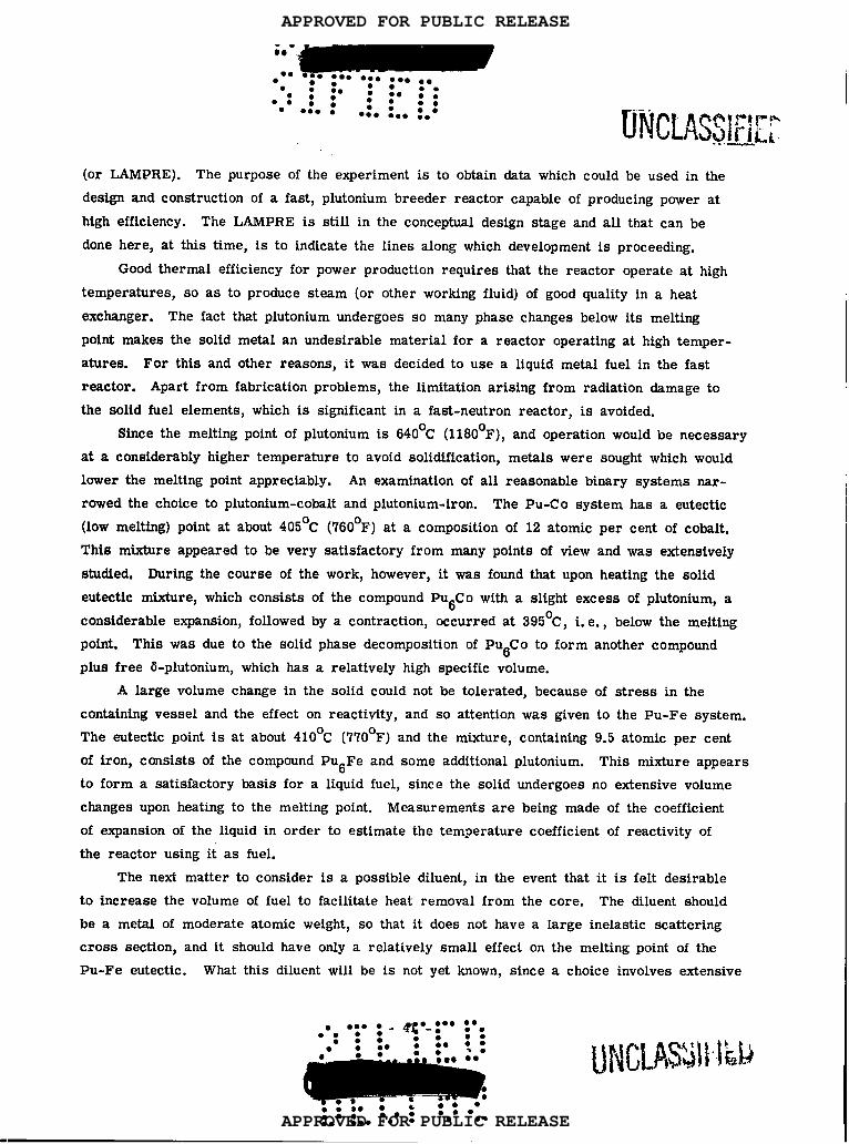
(or LAMPRE). The purpose of the experiment is to obtain data which could be used in the
design and construction of a fast, plutonium breeder reactor capable of producing power at
high efficiency. The LAMPRE is still in the conceptual design stage and all that can be
done here, at this time, is to indicate the lines along which development is proceeding.
Good thermal efficiency for power production requires that the reactor operate at high
temperatures, so as to produce steam (or other working fluid) of good quality in a heat
exchanger. The fact that plutonium undergoes so many phase changes below its melting
point makes the solid metal an undesirable material for a reactor operating at high temper-
atures. For this and other reasons, it was decided to use a liquid metal fuel in the fast
reactor. Apart from fabrication problems, the limitation arising from radiation damage to
the solid fuel elements, which is significant in a fast-neutron reactor, is avoided.
Stnce the melting point of plutonium is 640°C (1180°F), and operation would be necessary
at a considerably higher temperature to avoid solidification, metals were sought which would
lower the melting point appreciably. An examination of all reasonable binary systems mr -
rowed the choice to plutonium-cobalt and plutonium-iron. The Pu-C o system has a eutectic
(low melting) point at about 405°C (760°F) at a composition of 12 atomic per cent of cobalt.
This mixture appeared to be very satisfactory from many points of view and was extensively
studied. During the course of the work, however, it was found that upon heating the solid
eutectic mixture, which consists of the compound PU6C o with a slight excess of plutonium, a
considerable expansion, followed by a contraction, occurred at 395°C, i. e., below the melting
point. This was due to the solid phase decomposition of PU6C o to form another compound
plus free 6-plutonium, which has a relatively high specific volume.
A large volume change in the solid could not be tolerated, because of stress in the
containing vessel and the effect on reactivity, and so attention was given to the Pu-Fe system.
The eutectic point is at about 410°C (770°F) and the mixture, containing 9.5 atomic per cent
of iron, consists of the compound Pu6Fe and some additional plutonium. This mixture appears
to form a satisfactory basis for a liquid fuel, sine e the solid undergoes no extensive volume
changes upon heating to the melting point. Measurements are being made of the coefficient
of expansion of the liquid in order to estimate the temperature coefficient of reactivity of
the reactor using it as fuel.
The next matter to consider is a possible diluent, in the event that it is felt desirable
to increase the volume of fuel to facilitate heat removal from the core. The diluent should
be a metal of moderate atomic weight, so that it does not have a large inelastic scattering
cross section, and it should have only a relatively small effect on the melting point of the
Pu-F e eutectic. What this diluent will be is not yet known, since a choice involves extensive
‘w: IJNCLASJll!kb● **9● 9* ●0: ● *O8s●*eO** ●*
APPROVED FOR PUBLIC RELEASE
APPROVED FOR PUBLIC RELEASE

‘a&!!Hi#9*
● . . : .:0..0 .:... ●● 0 9*● 9 .: *:*.
. . ●0: ● O*
studies of ternary systems, i. e., Pu-Fe-diluent. A possible choice, at least from the metal-
lurgical standpoint, is cerium, but whether this will satisfy other requirements is questionable.
An alternative suggestion is to employ an indirect diluent in the form of a liquid metal
coolant. The desired result, of facilitating the heat removal, could be achieved by increasing
the volume (and heat-transfer area) of the cooling tubes of the heat-exchanger. As will be
seen below, these tubes are surrounded by the molten fuel, and the ultimate effect is the
same as adding a diluent to the liquid fuel.
A further problem is the selection of the material to contain the molten plutonium alloy
at a temperature of about 600°C (1, 100°F). This has been provisionally set as the operating
temperature of the reactor. Of the relatively few high-melting point metals, which do not
dissolve in molten plutonium, only tantalum, tungsten, and niobium seem to offer prospects
for use as the container material. Tantalum appears to be the best choice because of its
resistant e to attack and relatively simple fabrication.
As the coolant, preference is being given to liquid sodium. This is the coolant used
in the SIR and is to be used in the EBR-Jl. There has been considerable experience with
this liquid metal circulating at high temperatures, and in spite of its hazardous nature, it is
widely favored in the reactor field. Sodium can be used at high temperatures without the
necessity for pressurization, and it has excellent heat-transfer properties.
In the LAMPRE the liquid sodium would flow through a heat exchanger, consisting of a I
large number of vertical tantalum tubes, surrounded by the molten plutonium alloy. The
coolant would flow through the interior of these tubes. The ability of tantalum to withstand I!
the action of molten sodium at high temperatures, flowing at high velocity, is as yet unknown.
It may be mentioned that some consideration is being given to the possibility of employ-
ing liquid bismuth as the coolant in place of sodium. The heat-transfer properties of bismuth
are not as good as those of sodium and it has a higher melting point, so that it is more
likely to solidify in the heat-exchanger tubes during shut-down. On the other hand, bismuth
is less chemically reactive than sodium, and probably will not attack tantalum. In addition,
it may well be less effective than sodium in slowing down neutrons.
Treatment of Spent Fast-Reactor Fuel
Because of the small capture cross sections for fast neutrons, fission product poisoning
is not a serious problem in a fast reactor. This is particularly the case due to the circum-
stance that the fission products formed in largest amounts happen to have the smallest capture
cross sections. Essentially, therefore, the fission products are to considered merely as
impurities which dilute the fuel, thus decreasing its reactivity. The problem in the treatment
of the spent fuel from a fast reactor is thus to decrease the total proportion of impurities,
APPROVED FOR PUBLIC RELEASE
APPROVED FOR PUBLIC RELEASE

:’0● 9
::● ,
00●
●
● :● ,
● ☛☛.9* : ● .
:0 . .OO .b. :
:
● *. ● ee ● *. .*
: :0 ::...9**
::):0 : :.O
●:* ● 00 . .
irrespective of their nature. If the reactor employed solid fuel elements, which required fabrica-
tion, the radioactivity y would have to be considered. But for the LAMPRE this will not be necessary.
The plutonium fuel could be purified by dissolving it in nitric acid and extracting with
TBP, in a manner similar to that described above for the LAPRE solutions. In this event,
however, the plutonium metal would have to be re- extracted from the solution. In order to
simpltfy the treatment of spent plutonium fuel, work is being done on the development of
“pyrometallurgical” methods, using melts at high temperatures instead of aqueous solutions
at ordinary temperatures. If such methods can be worked out, the dissolution of the pluto-
nium metal in acid and its subsequent recovery from solution will be avoided.
Although the pyrometallurgical treatment of uranium fuels has been extensively investi-
gated, similar studies with plutonium have only recently been started. For this purpose an
artificial so-called “fissium alloy” is prepared to simulate plutonium fuel in which about 10
per cent of the original plutonium-239 has undergone fission. In actual practice, spent fuel
would contain 30 or more clifferent elements, some present as traces. For the preparation
of the fissium alloy, however, only four impurities, namely, zirconium, molybdenum, ruthe-
nium, and cerium, are added to the plutonium-iron (or plutonium-cobalt) mixture. These
four elements were chosen for two reasons: first, they are formed in relatively large pro-
portions in the fission process, and, second, reasonably accurate analytical methods for their
quantitative determination are available. Since the purpose of the fuel treatment is to remove
the bulk of the impurities, irrespective of their mture, the fissium alloy which can be
readtly prepared in the laboratory and is no more difficult to handle than plutonium itself,
is a convenient experimental material.
One of the pyrometallurgical methods of purification being studied with fissium alloy
involves oxide slagging. The material is melted and heated to over 1, 300°C (2, 350°F) in a
magnesium oxide crucible. The basic idea is that impurity metals will react with the oxygen
to form oxides which rise to the surface of the melt and can be removed as slag. The
qesium re~in~g is volatilized at the high temperature of the system. There are indi-
cations that cerium can be removed almost completely from fissium alloy in this manner,
but the removal of zirconium and molybdenum is less effective. Ruthenium, on the other
hand, is hardly affected.
Carbide slagging has been attempted, but has not proved too successful. A complicating
factor here is the extensive formation of plutonium carbide. An investigation is being planned
of fluoride slagging, using a crucible of anhydrous cobalt f Iuoride as the source of fluorine.
A possible method of, at least partial, purification by liquation is based on the suppo-
sition that some of the fission products will be present in the spent fuel in amounts in excess
● ● 9O ●● ** 9** ● *
● *: :. 43:-: : :● ● *● 0:.::. m.
● . . .:0 ..0 GO* ● ** ● 0
APPROVED FOR PUBLIC RELEASE
APPROVED FOR PUBLIC RELEASE

● m . - ---● ●°0 ● 00 ● 9*
● .00: ●009
● ● *9 ●.09
● **:● **:... .
9*● 0
● ● ..*
. . ●.: ●:0 ● ● 90
wtc} IFJ)p.t--~q“~ +@
of their equilibrium volubility. It should then. be -possible to e~ec~ some separation by
holding the material in the molten state (at about 480°C or less) and allowing the insoluble
elements (or their inter metallic compounds) to rise to the surface. This is possible because
of the high density of moIten plutonium. Preliminary work indicates that zirconium, molyb-
denum, and, to a lesser degree, ruthenium may perhaps be removable by this method.
Another procedure for the purification of plutonium which is being investigated involves
electrolysis in a fused salt bath. A possible electrolyte is a eutectic mixture of plutonium
trichloride and sodium chloride, with a melting point of 430°C. It is hoped that it may be
possible by electrolysis to transfer plutonium from an anode of molten spent fuel to a cathode,
leaving the impurities behind,
A final idea that is being given consideration is a liquid-extraction process using a
liquid metal as the extractant. Such a metal should form a two-phase liquid system with
plutonium, the mutual volubility of the two metals being small. The only promising indication
for such an extractant at the present time is lanthanum. While it is known that the liquid
metal does not mix appreciably with liquid plutonium, the solubilities of the fission product
impurities in the lanthanum-rich layer have not been investigated.
References
For further information on the Los Alamos Reactor Experiments, the following refer-
ences ;ay be consulted:
LAPRE I LAMS-1611
LAPRE II LA-1942
● ✎ ,ao .*.● I ● 9 . . .
●44 -: : :.0:-0::. .O● - ●* ●:0● 0 ●0: ●:0 ●0: ● 00 . .
APPROVED FOR PUBLIC RELEASE
APPROVED FOR PUBLIC RELEASE